Embed Size (px)
DESCRIPTION
Develop an Induction Machine on FPGA compatible with OPAL-RT eFPGAsim suite Use OPAL-RT Electric Hardware Solver (eHS) module for power electronic
Citation preview
An Induction Machine and Power Electronic Test System on FPGA
Christian Dufour Sébastien Cense Jean Bélanger
OPAL-RT TECHNOLOGIES, Montréal, Québec, Canada
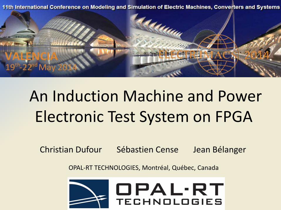
Objective of the work• Develop an Induction Machine on FPGA
compatible with OPAL-RT eFPGAsim suite• Use OPAL-RT Electric Hardware Solver (eHS)
module for power electronic
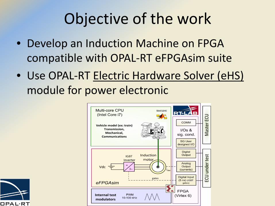
Advantages of FPGA simulation• Excellent resolution for high frequency IGBT gating
(up to 50-100 kHz)• Excellent latency (typ. 1 µs) for direct current-control
motor applications or FODP (Fast On-board Drive Protection)
• Massively parallel pre-processing unit for CPU– very good example: MMC converters
ALU cores
I/O
s
DUT
(con
trol
ler)Logic & mem
CPU FPGA
PCIe bus
FOBP
Disadvantages of FPGA simulation• Higher coding complexity than CPU counterparts.
– User has more control over lower level abstraction levels but this increases the complexity of the designs
– Many basic CPU coding schemes must be explicited in the FPGA design. Ex: ‘for’ loops in matrix multiplications.
• Very long compilation time– Generating a new FPGA bitstream from FPGA code can take 1-2
hours on big FPGA chips like Virtex-6 or Virtex-7
• Increased debugging/probing difficulty OPAL-RT designed eFPGAsim and eHS to solve theseproblems
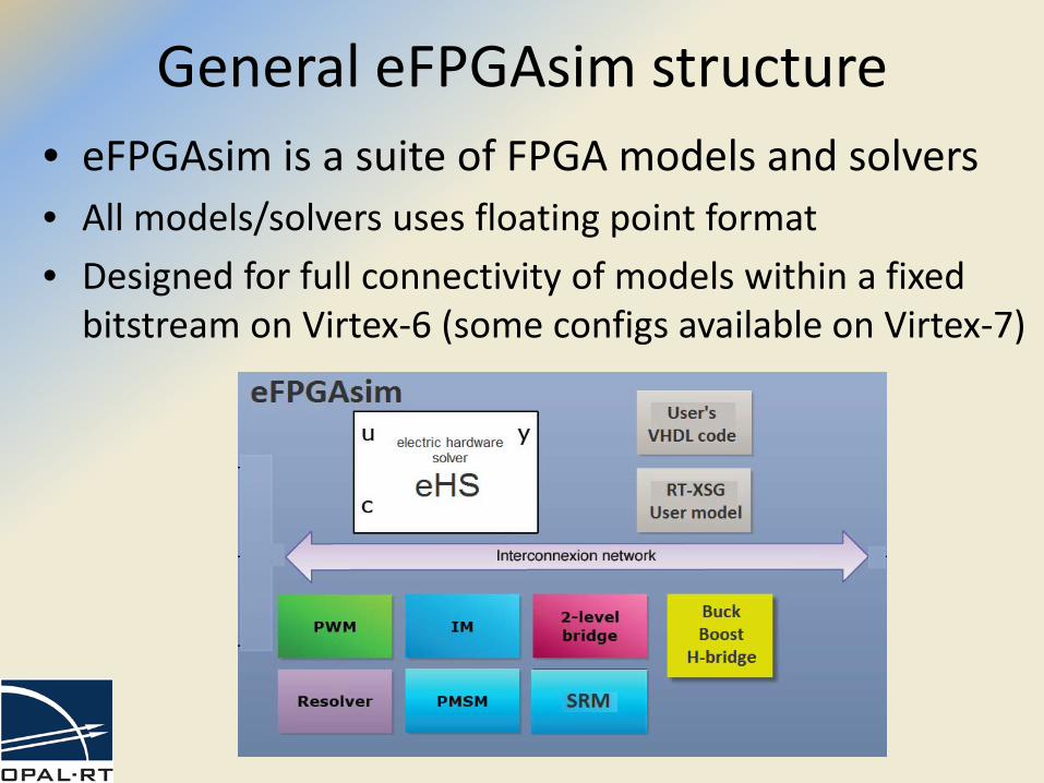
General eFPGAsim structure• eFPGAsim is a suite of FPGA models and solvers• All models/solvers uses floating point format• Designed for full connectivity of models within a fixed
bitstream on Virtex-6 (some configs available on Virtex-7)
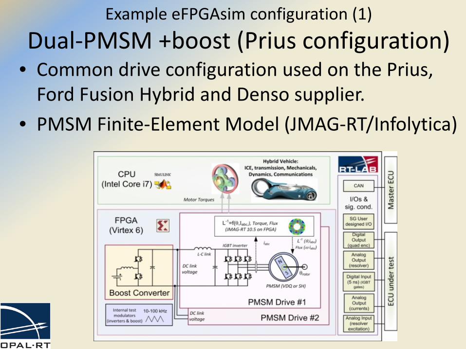
Example eFPGAsim configuration (1)
Dual-PMSM +boost (Prius configuration)• Common drive configuration used on the Prius,
Ford Fusion Hybrid and Denso supplier.• PMSM Finite-Element Model (JMAG-RT/Infolytica)
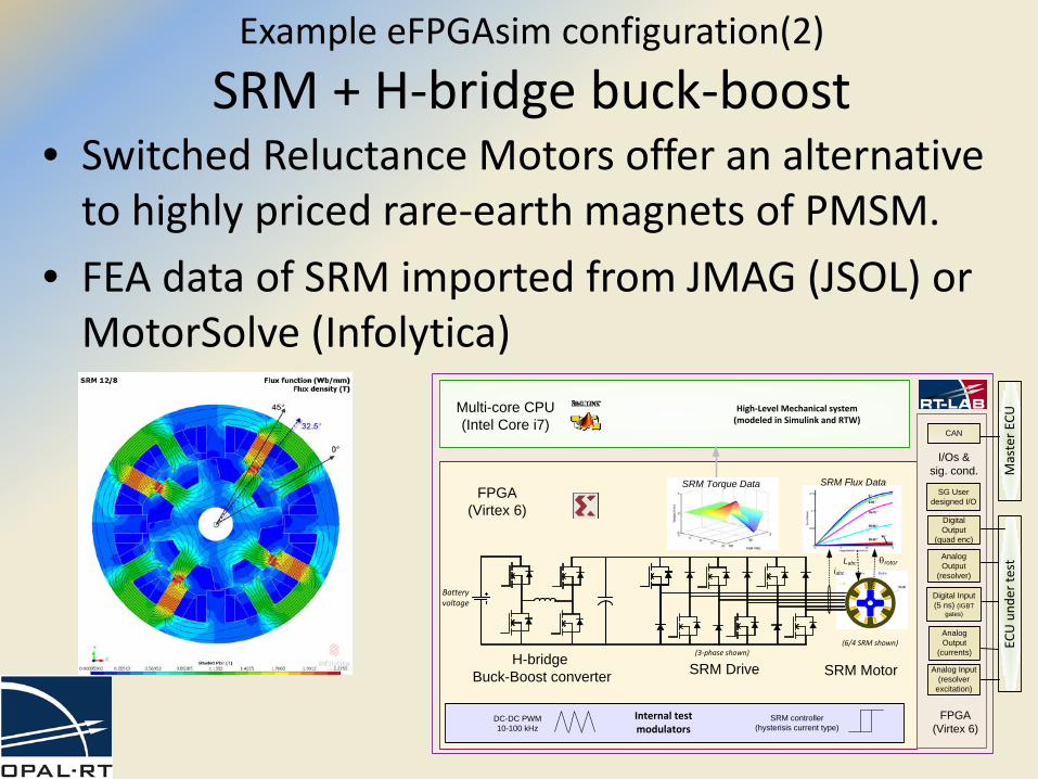
Example eFPGAsim configuration(2)
SRM + H-bridge buck-boost• Switched Reluctance Motors offer an alternative
to highly priced rare-earth magnets of PMSM.• FEA data of SRM imported from JMAG (JSOL) or
MotorSolve (Infolytica)
(3-phase shown)
L-1 (θ,iabc)
θrotor
FPGA(Virtex 6)
Digital Input (5 ns) (IGBT
gates)
Multi-core CPU(Intel Core i7)
Internal testmodulators
DC-DC PWM10-100 kHz
SRM Drive
Analog Output
(currents)
Analog Output
(resolver)
Digital Output
(quad enc)
I/Os &sig. cond.
Analog Input(resolver
excitation)
High-Level Mechanical system(modeled in Simulink and RTW)
Mas
ter E
CU
Batteryvoltage
H-bridge Buck-Boost converter
SG User designed I/O
ECU
und
er te
st
CAN
(6/4 SRM shown)
SRM Motor
SRM Flux Data
Labc
SRM controller(hysterisis current type)
SRM Torque Data
iabc
FPGA(Virtex 6)
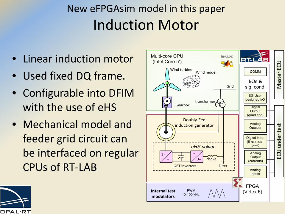
New eFPGAsim model in this paper
Induction Motor
• Linear induction motor• Used fixed DQ frame.• Configurable into DFIM
with the use of eHS• Mechanical model and
feeder grid circuit can be interfaced on regular CPUs of RT-LAB
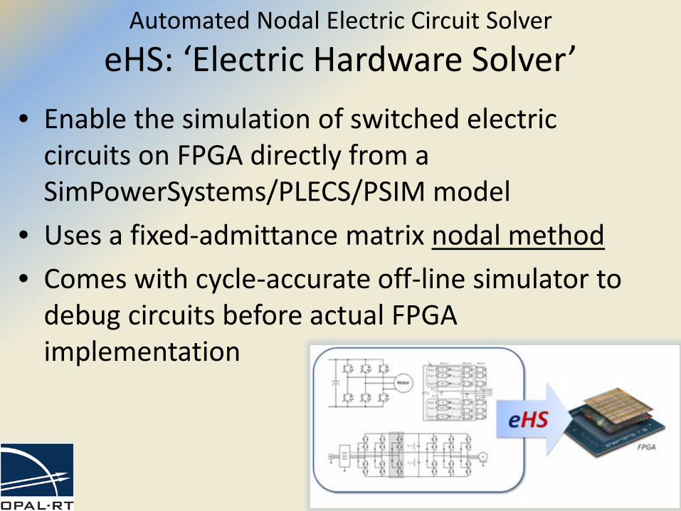
Automated Nodal Electric Circuit Solver
eHS: ‘Electric Hardware Solver’ • Enable the simulation of switched electric
circuits on FPGA directly from a SimPowerSystems/PLECS/PSIM model
• Uses a fixed-admittance matrix nodal method• Comes with cycle-accurate off-line simulator to
debug circuits before actual FPGA implementation
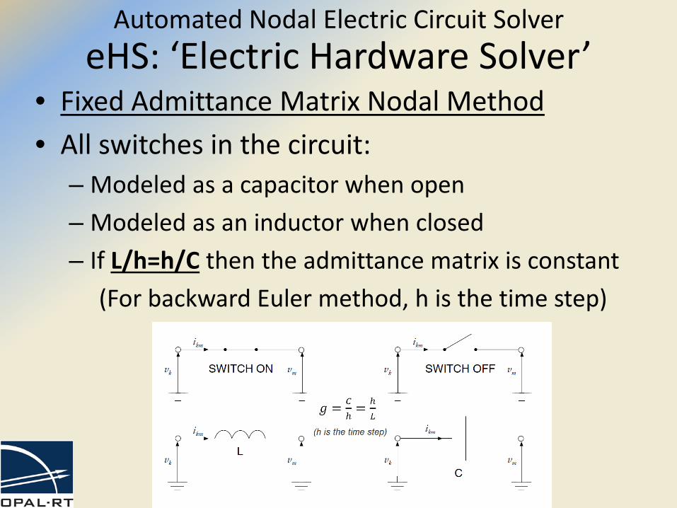
• Fixed Admittance Matrix Nodal Method• All switches in the circuit:
– Modeled as a capacitor when open– Modeled as an inductor when closed– If L/h=h/C then the admittance matrix is constant
(For backward Euler method, h is the time step)
Automated Nodal Electric Circuit SolvereHS: ‘Electric Hardware Solver’
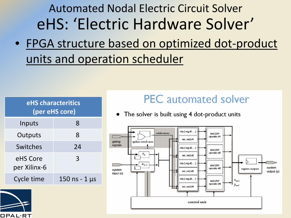
• FPGA structure based on optimized dot-product units and operation scheduler
Automated Nodal Electric Circuit SolvereHS: ‘Electric Hardware Solver’
eHS characteritics(per eHS core)
Inputs 8
Outputs 8
Switches 24
eHS Coreper Xilinx-6
3
Cycle time 150 ns - 1 µs
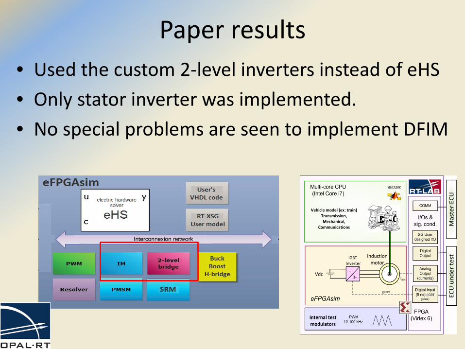
• Used the custom 2-level inverters instead of eHS• Only stator inverter was implemented.• No special problems are seen to implement DFIM
Paper results
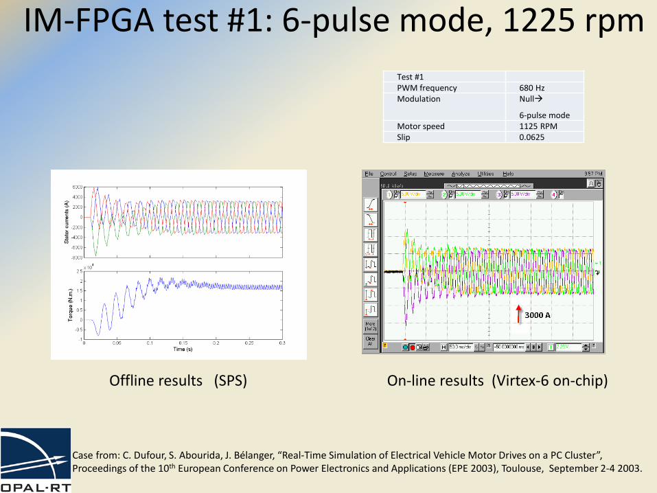
Offline results (SPS) On-line results (Virtex-6 on-chip)
IM-FPGA test #1: 6-pulse mode, 1225 rpmTest #1PWM frequency 680 HzModulation Null
6-pulse modeMotor speed 1125 RPMSlip 0.0625
Case from: C. Dufour, S. Abourida, J. Bélanger, “Real-Time Simulation of Electrical Vehicle Motor Drives on a PC Cluster”, Proceedings of the 10th European Conference on Power Electronics and Applications (EPE 2003), Toulouse, September 2-4 2003.
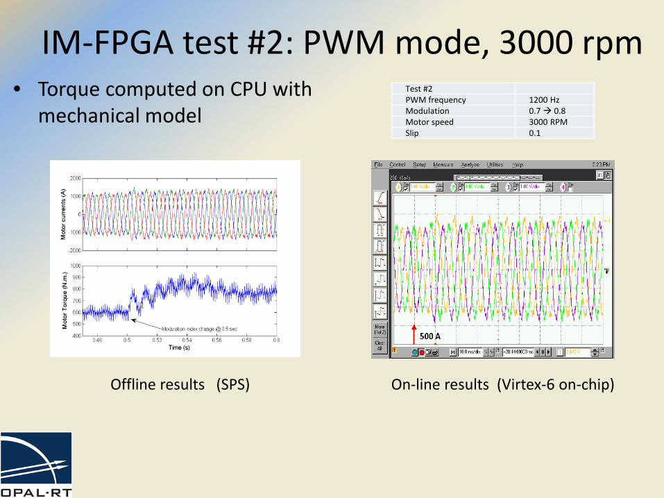
IM-FPGA test #2: PWM mode, 3000 rpm• Torque computed on CPU with
mechanical modelTest #2PWM frequency 1200 HzModulation 0.7 0.8Motor speed 3000 RPMSlip 0.1
Offline results (SPS) On-line results (Virtex-6 on-chip)
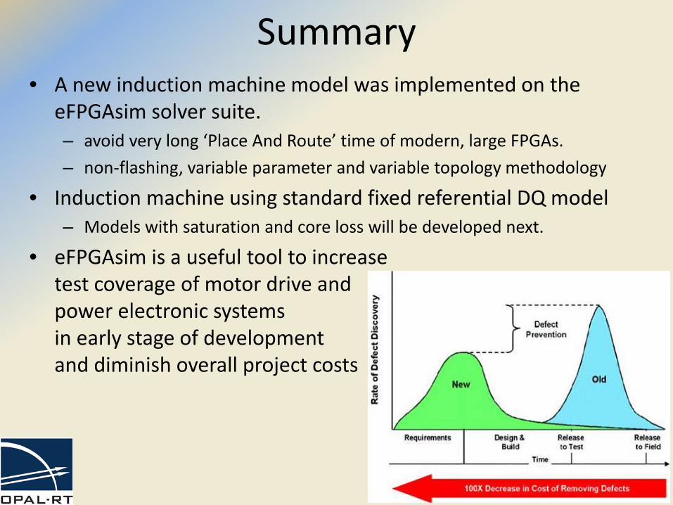
Summary• A new induction machine model was implemented on the
eFPGAsim solver suite.– avoid very long ‘Place And Route’ time of modern, large FPGAs.– non-flashing, variable parameter and variable topology methodology
• Induction machine using standard fixed referential DQ model– Models with saturation and core loss will be developed next.
• eFPGAsim is a useful tool to increasetest coverage of motor drive andpower electronic systemsin early stage of developmentand diminish overall project costs