Embed Size (px)
Citation preview
Magnetic Flux Controlin Induction Installations
Dr. Valentin NemkovDirector of Research
Fluxtrol, Inc., USA
Padua, Italy, May 21-24, 2013
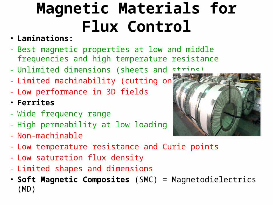
Magnetic Materials for Flux Control• Laminations:- Best magnetic properties at low and middle frequencies and high
temperature resistance- Unlimited dimensions (sheets and strips)- Limited machinability (cutting only)- Low performance in 3D fields• Ferrites- Wide frequency range- High permeability at low loading- Non-machinable- Low temperature resistance and Curie points- Low saturation flux density- Limited shapes and dimensions• Soft Magnetic Composites (SMC) = Magnetodielectrics (MD)
Magnetic Materials for Flux Control• Soft Magnetic Composites (SMC) = Magnetodielectrics- Very wide frequency range (up to 13 MHz)- Good magnetic and thermal properties- Excellent machinability (not for all types)- Work well in 3D fields- Limited dimensions- Higher stock price than laminations • Combination of laminations in large regular areas and
SMC in 3D and complex geometry areas is very promising for induction installations of low and middle frequencies
Magnetic Flux Control
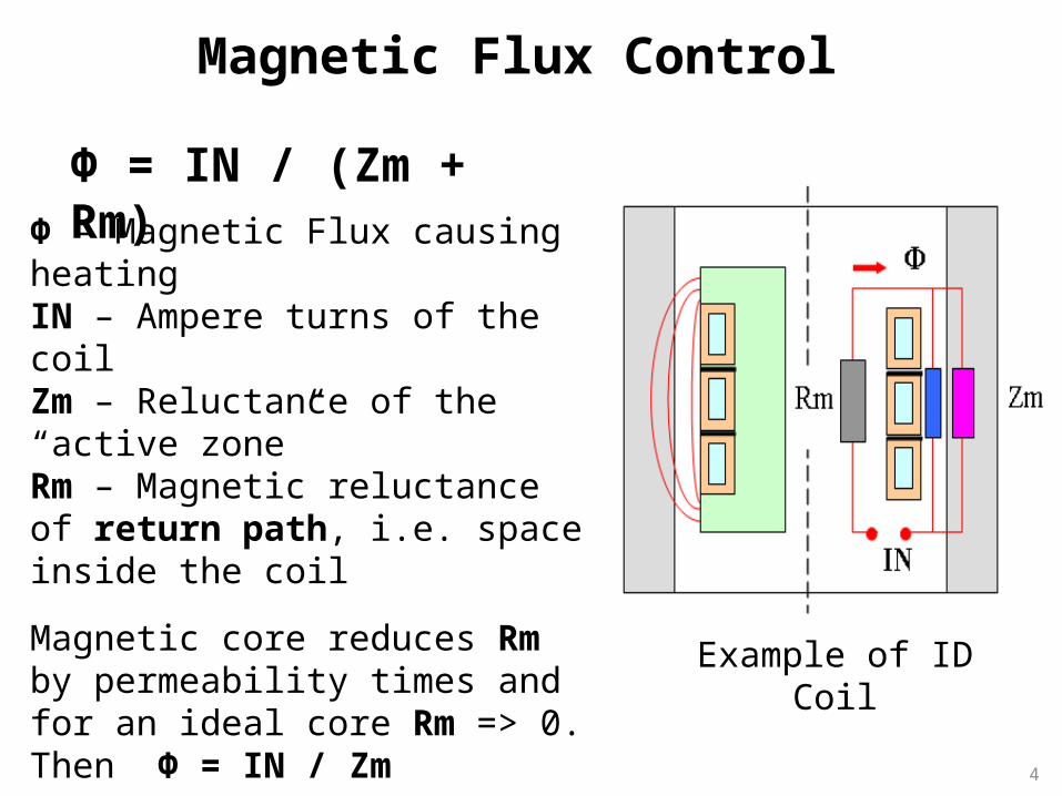
Φ = IN / (Zm + Rm)Φ – Magnetic Flux causing heatingIN – Ampere turns of the coil Zm – Reluctance of the “active zone”Rm – Magnetic reluctance of return path, i.e. space inside the coil
Magnetic core reduces Rm by permeability times and for an ideal core Rm => 0.Then Φ = IN / Zm
Magnetic flux control is the most effective when there are “bottle necks” on the flux return path
Example of ID Coil
4
5
Magnetic Control in Induction Heat Treating and Brazing
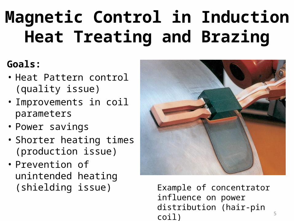
Goals:• Heat Pattern control
(quality issue)• Improvements in coil
parameters• Power savings• Shorter heating times
(production issue)• Prevention of unintended
heating (shielding issue) Example of concentrator influence on power distribution (hair-pin coil)

Single-shot Induction Coil with Laminations
Photo Courtesy of Tucker Induction
Lamination stacks
Examples of Coils with SMC Controllers
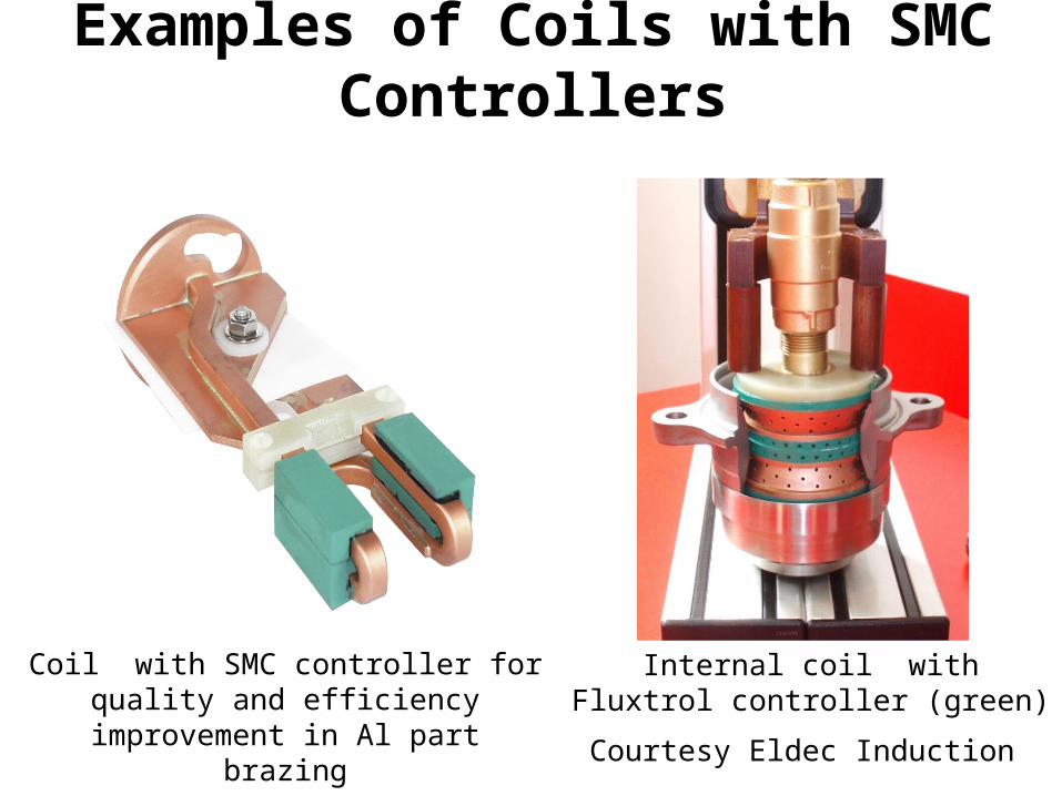
Coil with SMC controller for quality and efficiency improvement in Al part brazing
Frequency 25 kHz
Internal coil with Fluxtrol controller (green)
Courtesy Eldec Induction
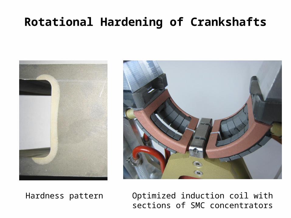
Rotational Hardening of Crankshafts
Hardness pattern Optimized induction coil with sections of SMC concentrators
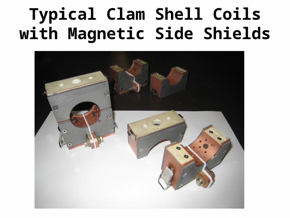
Typical Clam Shell Coils with Magnetic Side Shields
Magnetic Control in Coreless Melting Furnaces
• Improvement of furnace parameters (efficiency, power factor)
• Optimal distribution of power in the melt• Induction coil shielding:
- reduction of losses in the furnace structure- reduction of losses in chamber and possibility to reduce the chamber diameter (vacuum furnaces)- field reduction on work places (Maximum Permissible Levels compliance)
• Special applications such as Cold Crucible Furnaces
11
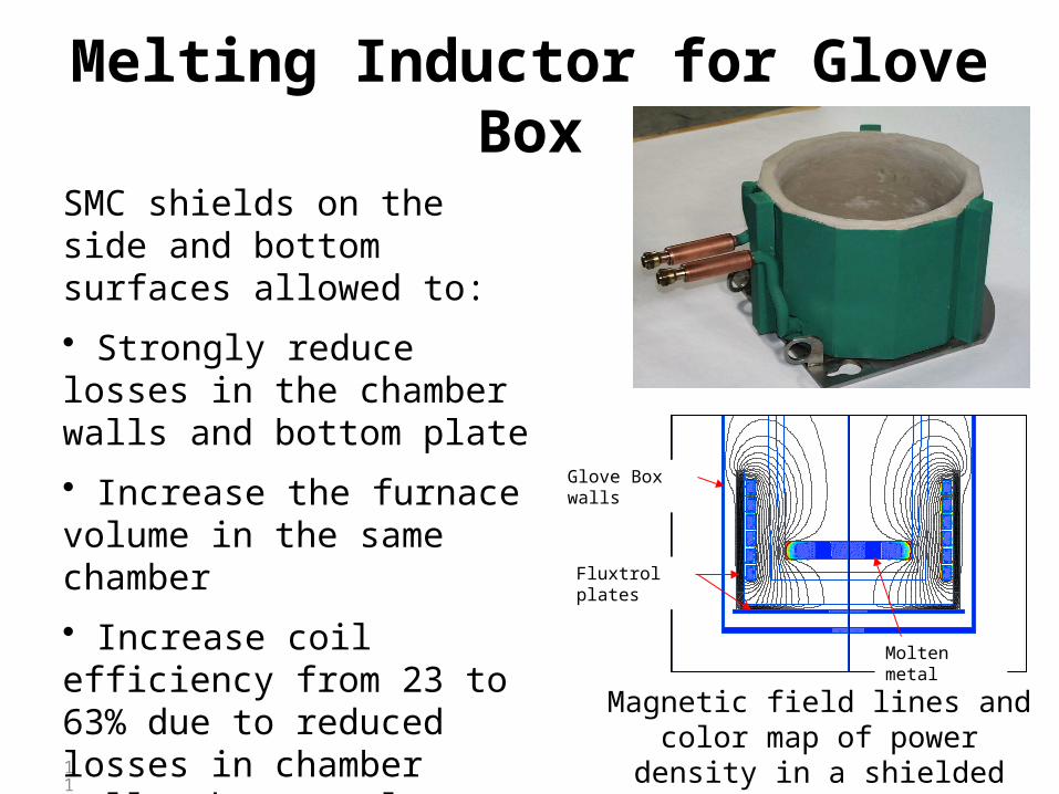
Melting Inductor for Glove Box
SMC shields on the side and bottom surfaces allowed to:
• Strongly reduce losses in the chamber walls and bottom plate
• Increase the furnace volume in the same chamber
• Increase coil efficiency from 23 to 63% due to reduced losses in chamber walls, bottom plate and in the coil
Fluxtrol A plates
Magnetic field lines and color map of power density in a shielded coil
Glove Box walls
Fluxtrol plates
Molten metal
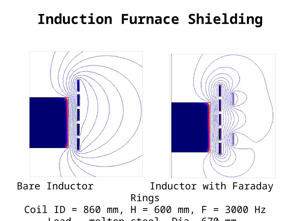
Induction Furnace Shielding
Bare Inductor Inductor with Faraday RingsCoil ID = 860 mm, H = 600 mm, F = 3000 Hz
Load – molten steel, Dia. 670 mm
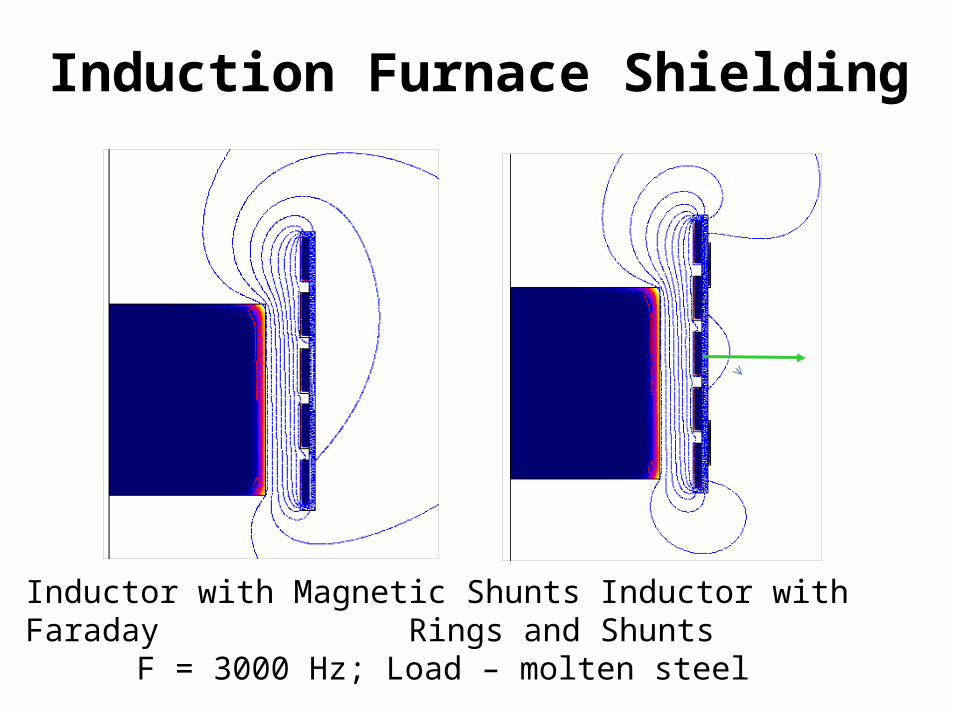
Induction Furnace Shielding
Inductor with Magnetic Shunts Inductor with Faraday Rings and Shunts
F = 3000 Hz; Load – molten steel
14
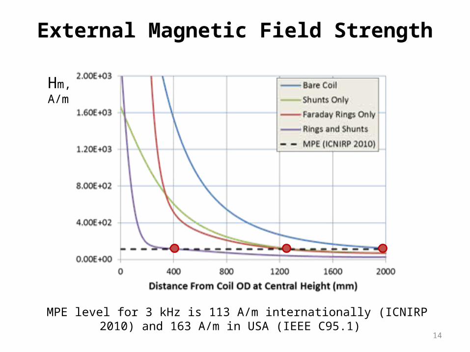
External Magnetic Field Strength
MPE level for 3 kHz is 113 A/m internationally (ICNIRP 2010) and 163 A/m in USA (IEEE C95.1)
Hm, A/m
15
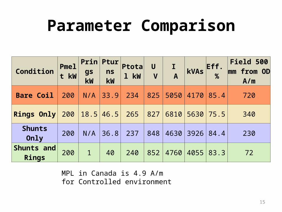
Parameter Comparison
Condition Pmelt kW
Prings kW
Pturns kW
Ptotal kW
U V
I A kVAs Eff.
%Field 500 mm from OD A/m
Bare Coil 200 N/A 33.9 234 825 5050 4170 85.4 720
Rings Only 200 18.5 46.5 265 827 6810 5630 75.5 340
Shunts Only 200 N/A 36.8 237 848 4630 3926 84.4 230
Shunts and Rings 200 1 40 240 852 4760 4055 83.3 72
MPL in Canada is 4.9 A/m for Controlled environment
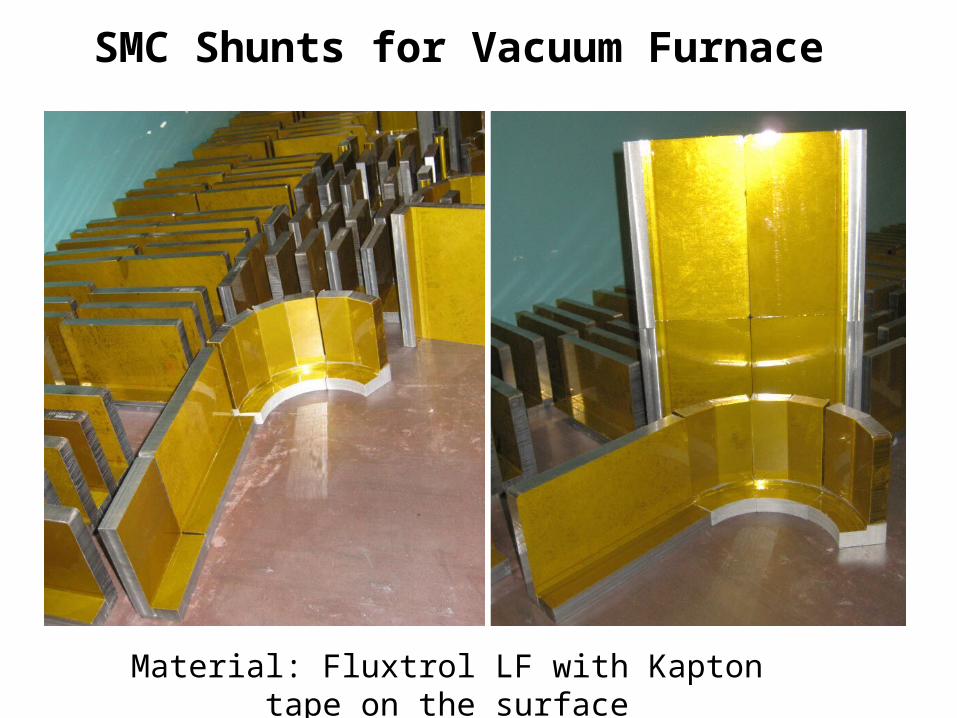
SMC Shunts for Vacuum Furnace
Material: Fluxtrol LF with Kapton tape on the surface
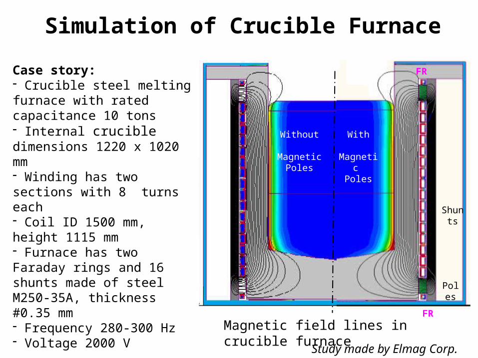
Simulation of Crucible Furnace
Magnetic field lines in crucible furnace
Shunts
Poles
FR
FR
With Magnetic
Poles
Without Magnetic
Poles
Study made by Elmag Corp.
Case story:- Crucible steel melting furnace with rated capacitance 10 tons- Internal crucible dimensions 1220 x 1020 mm- Winding has two sections with 8 turns each- Coil ID 1500 mm, height 1115 mm- Furnace has two Faraday rings and 16 shunts made of steel M250-35A, thickness #0.35 mm- Frequency 280-300 Hz- Voltage 2000 V
Innovations in simulation:- Use of magnetic poles made of Fluxtrol LF- Losses in magnetic materials are taken into account
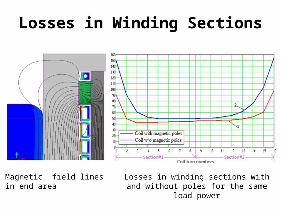
Losses in Winding Sections
Magnetic field lines in end area Losses in winding sections with and without poles for the same load power
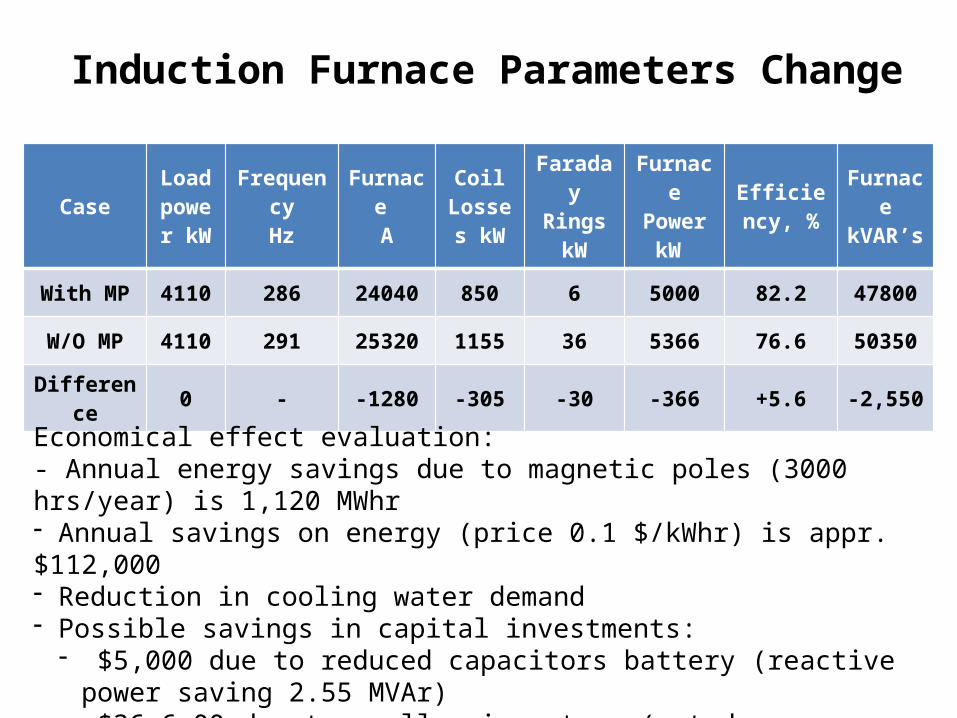
Induction Furnace Parameters Change
CaseLoad
power kW
FrequencyHz
Furnace A
Coil Losses
kW
Faraday RingskW
Furnace Power
kW Efficiency,
%Furnace kVAR’s
With MP 4110 286 24040 850 6 5000 82.2 47800
W/O MP 4110 291 25320 1155 36 5366 76.6 50350
Difference 0 - -1280 -305 -30 -366 +5.6 -2,550
Economical effect evaluation: - Annual energy savings due to magnetic poles (3000 hrs/year) is 1,120 MWhr - Annual savings on energy (price 0.1 $/kWhr) is appr. $112,000- Reduction in cooling water demand - Possible savings in capital investments:
- $5,000 due to reduced capacitors battery (reactive power saving 2.55 MVAr)- $36,6 00 due to smaller inverters (rated power may be reduced by 366 kW)
Magnetic Flux Control in Induction CC Furnace for Titanium Power Production
Project was performed in collaboration of Iowa State University, Ames* with Fluxtrol, Inc.
*Presentation: Advances in Ti Alloy Powder Production by Close-Coupled Gas Atomization
A.J. Heidloff, J.R. Rieken, D. Byrd, I.E. AndersonMaterials Science and Engineering, Iowa State University, Ames, IA
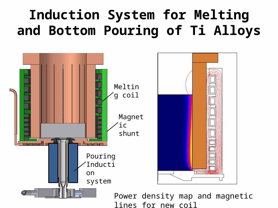
Induction System for Melting and Bottom Pouring of Ti Alloys
Power density map and magnetic lines for new coil
Magnetic shunt
Pouring Induction system
Melting coil

Results of Magnetic Shunts Installation
New induction coil with different turn density and magnetic shunts with poles increased system efficiency from 31 to 47%, allowed to pour more material from the crucible, improved matching of the furnace to generator and reduced water consumption per kg of powder by 25 % Ti-6Al-4V powder
Design Pmelt kW
Pcoil kW
Pleads kW
P cruckW
Ptotal kW
Eff-cy %
IkA
Origin 50 33.8 10.5 66.8 161 31 2.18
New 50 16.5 6.0 33.5 106 47 1.50

3D Study of CCF with Magnetic Controllers
“Wedge” with meshed surfaces:1 – shunts; 2 – poles; 3 – inserts; 4 – magnetic ring
Current density maps on CC fingers and on Faraday ring surfaces:A – no inserts and magnetic ring;B – with top and bottom inserts
1
23
4
A B
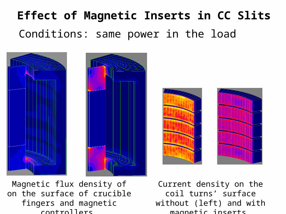
Conditions: same power in the loadEffect of Magnetic Inserts in CC Slits
Magnetic flux density of on the surface of crucible fingers and magnetic
controllers
Current density on the coil turns’ surface without (left) and with
magnetic inserts
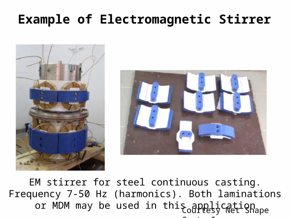
Example of Electromagnetic Stirrer
EM stirrer for steel continuous casting. Frequency 7-50 Hz (harmonics). Both laminations or MDM may be used in this application
Courtesy Net Shape Cast, Inc.
Conclusions
• Magnetic flux control in systems for induction heating and EM processing of materials is used for a very long time but is still under evaluated
• New materials and computer simulation allow us to optimize magnetic circuits and meet strict demands of industry
• Both Laminations and Soft Magnetic Composites may be used at lower frequencies (up to 20 kHz)
• For higher frequencies SMC may be effectively used with some competition from ferrites