Embed Size (px)
Citation preview
Article citation info:
Bednarz SA, Dybkowski M. Induction motor windings faults detection using flux-error based MRAS estimators. Diagnostyka.
2019;20(2):87-96. http://dx.doi.org/10.29354/diag/109092
87
DIAGNOSTYKA, 2019, Vol. 20, No. 2
ISSN 1641-6414 e-ISSN 2449-5220
DOI: 10.29354/diag/109092
INDUCTION MOTOR WINDINGS FAULTS DETECTION USING FLUX-ERROR
BASED MRAS ESTIMATORS
Szymon Antoni BEDNARZ, Mateusz DYBKOWSKI
Wrocław University of Science and Technology, Department of Electrical Machines,
Drives and Measurements, Smoluchowskiego 19, 50-370, Wrocław, Poland
[email protected]; [email protected]
Abstract
The paper is concerned with detection of a stator and rotor winding faults in a squirrel-cage induction
motor. The idea of the fault detection is based on a hypothesis that each of windings faults results in a sharp
increase or decrease of internal parameters’ values of the machine, therefore it can be treated as a suitable
fault symptom. Resistances of the stator and rotor windings seem to be adequate quantities due to their direct
relationship with the machine windings. An observation and analysis of the parameters’ changes in a real-
time domain enables to an incipient detection of the fault. It is evident that internal parameters of the machine
can’t be measured directly during operation on the drive system thus the only way is an estimation by
specialized algorithms. In the paper two estimators based on Model Reference Adaptive System (MRAS)
were utilized to achieve this goal. Two simple algorithms for faults detection are proposed as well. Detailed
description of fault detection systems is included in the paper. Proposed systems were tested on computer
simulations performed by MATLAB/Simulink software. Then, experimental tests were carried out on the
laboratory setup to confirm usefulness of proposed approaches.
Keywords: induction motor, stator fault, rotor fault, faults detection, parameter estimator, MRAS
DETEKCJA USZKODZEŃ UZWOJEŃ SILNIKA INDUCKYCJNEGO Z ZASTOSOWANIEM
ESTYMATORÓW MRAS BAZUJĄCYCH NA BŁĘDZIE ESTYMACJI STRUMIENIA
Streszczenie
Artykuł skupia się na wykrywaniu wybranych uszkodzeń uzwojeń stojana i wirnika silnika indukcyjnego
klatkowego. Idea detekcji opiera się na założeniu, że każde uszkodzenie uzwojeń powoduje gwałtowną
zmianę wartości wewnętrznych parametrów maszyny, co może być uznane jako miarodajny symptom
uszkodzenia. Najbardziej odpowiednimi parametrami wydają się być rezystancje stojana i wirnika ze względu
na bezpośrednie powiązanie z uzwojeniami silnika. Obserwacja i analiza zmian wartości tych parametrów w
czasie rzeczywistym umożliwia wykrycie uszkodzenia w jego wczesnym stadium. W trakcie pracy napędu
nie ma możliwości pomiaru rezystancji uzwojeń, dlatego też jedynym sposobem na uzyskanie informacji o
ich aktualnych wartościach jest estymacja z zastosowaniem wyspecjalizowanych algorytmów. W pracy do
realizacji tego celu zastosowano układy adaptacyjne z modelem odniesienia (MRAS). Ponadto
zaproponowano również dwa proste algorytmy detekcji uszkodzeń uzwojeń stojana i wirnika. W artykule
przedstawiono przegląd literatury dotyczący wykrywania uszkodzeń silnika indukcyjnego z zastosowaniem
estymatorów parametrów. Proponowane rozwiązanie zostało sprawdzone poprzez analizę symulacyjną
przeprowadzoną w środowisku MATLAB/Simulink a także zweryfikowane na stanowisku
eksperymentalnym.
Słowa kluczowe: silnik indukcyjny, uszkodzenie stojana, uszkodzenie wirnika, wykrywanie uszkodzeń, estymator
parametrów, MRAS
1. INTRODUCTION
Electric drives with induction motors (IM) are
basic components in various systems, such as
electric and hybrid cars, trams, trains, metro, power
plants and industrial machines [1].
During operation of any electrical drive, damage
of its components can be occurred including
sensors (electrical or mechanical), power
electronics devices and the machine [2], [3].
Internal faults of the machine can be divided into
mechanical and electrical [2], [4]. According to the
literature up to 40% of faults belong to the stator
windings and about 10% to the rotor winding.
Other faults are related to the bearing and
another machine’s components [5], [3]. Stator
windings damages are related to an insulation
degradation, what causes interturn short-circuit
(ITSC) within a coil, while broken rotor bars and
end-rings are electrical faults in the cage of the IM
[4]. Motor’s winding faults have a negative impact
on the operation of the drive, and they should be
detected as soon as possible, to avoid further
DIAGNOSTYKA, Vol. 20, No. 2 (2019)
Bednarz SA, Dybkowski M.: Induction motor windings faults detection using flux-error based …
88
degradation of the machine and enable a safety stop
of the drive [4], [6], [5], [3].
Several diagnostics techniques related to stator
and rotor windings faults have been developed.
One of the most popular method is the signal-
based (SB) diagnostic procedure [4], [6]. This
technique consists of an analysis of measured
signals such as: current, voltage, electromagnetic
flux, power, mechanical vibration, angular speed
and temperature [7], [3]. The analysis is performed
on time, frequency or time-frequency domains to
extract specific symptoms which are related to the
faults [4]. These methods often utilize signal
analysis techniques, which are based on the Fast
Fourier Transform (FFT), Short Time Fourier
Transform (STFT), Wavelet Transform (WT),
Hilbert Transform (HT) [6], [3] etc. To improve an
effectiveness of the faults diagnosis, these methods
are often supported by solutions based on artificial
intelligence (AI) (artificial neural networks (ANN),
fuzzy logic (FL)) [6], [3], [8].
Nowadays, it has become a standard, that IM’s
work in closed-loop control systems what enable to
precise regulation of IM’s electromagnetic torque
or the angular speed [1], [7]. However, closed-loop
control systems (including vector control
algorithms) can compensate effects of windings
faults, what complicates the extraction of the faults
symptoms from measured signals (f. ex. Stator
currents) [9], [10]. Several signal-based diagnostics
methods for closed-loop control systems are
developed and presented in papers [10], [11], [12],
[13], [14], [15], [16].
Another approach to damages detection is the
model-based (MB) fault diagnosis technique which
in general relies on a mathematical model of the
machine [4], [17], [18], [3]. One of these methods
is based on hypothesis, that winding faults
symptoms can be observed as changes (a sharp
decrease/increase, oscillations) of values of the IM
parameters [19], [20], [17]. This method requires an
identification of the IM parameters during its
operation. Several identification algorithms have
been utilized in a context to the IM’s stator or rotor
windings faults diagnosis. They have based on: last
square error minimization [20], Kalman Filter [22],
[22], [23], [24], [25], [26], [27], nonlinear
programming [21], state observers [23], [28], [29],
Moving Horizon Estimation, [30], [31], genetic
algorithm [31], Sparse grid optimization [32], trust-
region and Broyden-Fletcher-Goldfard-Shano (TR-
BFGS) technique [30], and Sliding Mode Observer
[34].
Despite, that many identification algorithms
have been tested in a context to the IM’s fault
detection, not all existing approaches have been
taken into consideration. One of them are
estimators based on Model Reference Adaptive
System (MRAS), which are often utilized in the IM
drives to calculate state variables and parameters of
the machine [35], [36], [37].
Therefore, in this paper a Flux-error based
MRAS estimators (F-MRAS) are used to the IM’s
parameters identification in order to rotor or stator
faults detection. Two estimators are utilized: first
one [38], [39] is used to the rotor resistance
estimation while second [40], [41] is used to the
stator resistance estimation. Estimated parameters
are utilized in faults detection algorithms, which are
based on two simple assumptions [39], [41]:
• first – connected with rotor windings faults –
rupture of a rotor’s bar(s) results in a sharp increase
of the estimated rotor resistance;
• second – connected with stator windings faults
– ITSC results in a sharp decrease of the estimated
stator resistance.
Due to the fact, that values of both resistances
are strongly dependent on windings temperature
(heating or cooling process), proposed algorithms
were tested also for this phenomenon.
Studies were performed in the closed-loop
control system based on Direct Field Oriented
Control (DFOC) structure.
In the paper results of computer simulation
studies are shown which were carried out by
MATLAB/Simulink software. Results of the
experimental validation are presented as well.
2. MATHEMATICAL MODELS OF THE
INDUCTION MOTOR AND DIRECT
FIELD ORIENTED CONTROL
STRUCTURE
During computer simulations, a mathematical
model of the IM with possibility to tests the stator
and rotor windings faults are necessary. In the
paper two types of mathematical models were used
which are described in the stationary reference
frame (α-β). The first model to the stator faults
analysis, the second one for the rotor faults
analysis. In this chapter the control structure is also
presented.
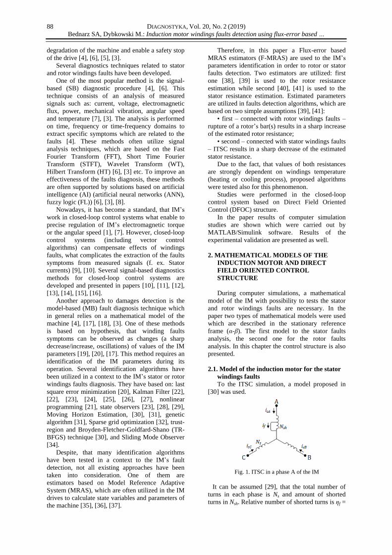
2.1. Model of the induction motor for the stator
windings faults
To the ITSC simulation, a model proposed in
[30] was used.
Fig. 1. ITSC in a phase A of the IM
It can be assumed [29], that the total number of
turns in each phase is Ns and amount of shorted
turns in Nsh. Relative number of shorted turns is ηf =
DIAGNOSTYKA, Vol. 20, No. 2 (2019)
Bednarz SA, Dybkowski M.: Induction motor windings faults detection using flux-error based …
89
Nsh/Ns. Fig. 1 illustrates the scheme of the IM’s
stator windings with a short circuit in the phase A.
An electromagnetic flux connected with the
faulted phase is given by:
Td
d
f
N s s f fT r r r it
αβ s αβμ i μ , (1)
where: rs – stator windings resistance, rf – shorted
circuit resistance, if – shorted circuit current, is-
stator current vector, 1 2N sNT f , |μαβ| is a
modulus and μα, μβ are components of the vector μαβ
= [μα, μβ]T which indicate the fraction of the shorted
turns and a phase of the short circuit respectively.
T
|A 1 0fAαβ
μ , (2)
T
|B
1 3
2 2fB
αβμ , (3)
T
|C
1 3
2 2fC
αβμ , (4)
where: ηfA, ηfB, ηfC – relative amount of shorted
turns for each phase.
The current in the short circuit can be obtain by
equation:
T
2
2
3
f
f
s
i
x
αβ s
αβ αβ
μ ψ
μ μ
, (5)
where: ψs – stator flux vector, xσs – stator leakage
reactance.
Stator and rotor fluxes are derived from voltage
equations:
3
d
d
2N s fT r i
t
s
s s αβ
ψu i μ , (6)
d
dN r mT r j
t r r
rψ
i ψ , (7)
where: us – stator voltage vector, ir – rotor voltage
vector, ψr – stator flux vector, rr – rotor windings
resistance, ωm – angular rotor speed.
The other IM equations are given by:
2
3
mr
f
xxi
w w s s r αβi ψ ψ μ , (8)
s mx x
w w r r si ψ ψ , (9)
2
Im 3
E fT i
*
s s αβψ i μ , (10)
d 1
d
m
E L
m
T Tt T
, (11)
where: TE – electromagnetic torque, TL – load
torque, xs , xr , xm – stator, rotor, mutual reactance,
respectively, Tm - mechanical constant.
2.2. Model of the induction motor for the rotor
windings faults
To the rotor bars damage simulation, the model
proposed in [41] was used. This model assumes that
a rupture of each of the rotor’s bar results in an
increase of the rotor resistance value. Rotor
resistance components in α-β coordinates system
are obtained by:
2
1
22 ( )sin
b
b rNr N
k b
N rr
kk
N
wG
, (12)
2
1
22 ( )sin
2
b
b rNr N
k b
N rr
kk
N
wG
, (13)
where: Nb –number of rotor bars, θ – angle of rotor
position, Gw – vector of rotor bars conductance,
where each element corresponds to rotor bar
condition (if Gw(k) = 0 – faulted, Gw(k) =1 -
healthy).
Rotor resistance components calculated by (12-
13) are used in the rotor voltage equation (7)
instead of the constant rr parameter. When Nb = 0
rotor resistance components are equal to the
nominal value of this quantity. During rotor bars
faults obtained rotor resistance components
oscillate, what results in stator currents modulation.
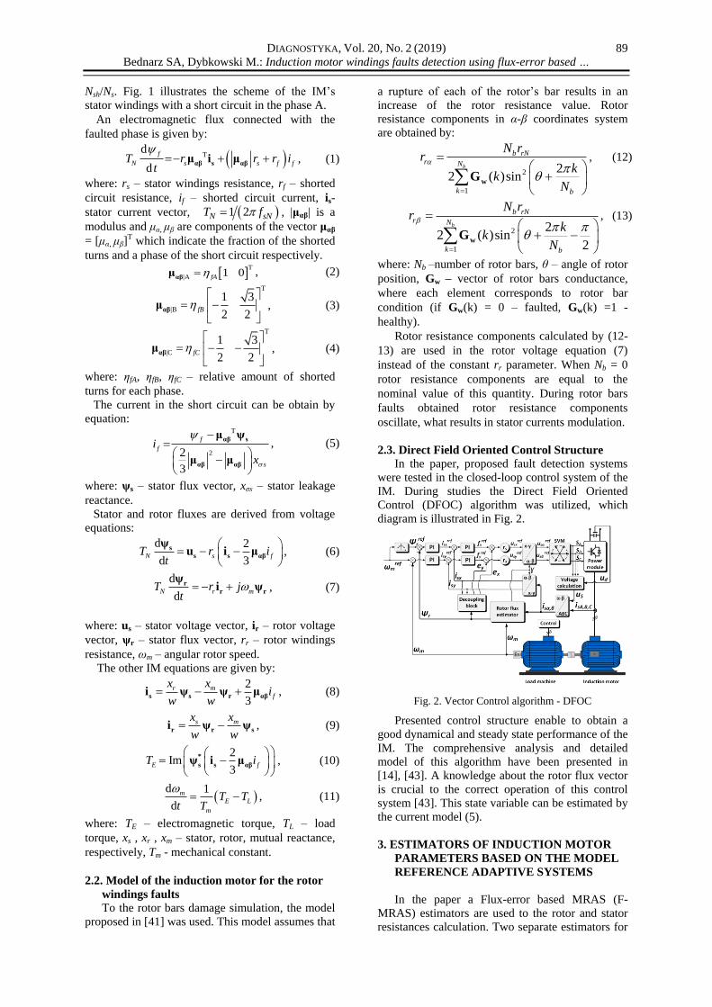
2.3. Direct Field Oriented Control Structure
In the paper, proposed fault detection systems
were tested in the closed-loop control system of the
IM. During studies the Direct Field Oriented
Control (DFOC) algorithm was utilized, which
diagram is illustrated in Fig. 2.
Fig. 2. Vector Control algorithm - DFOC
Presented control structure enable to obtain a
good dynamical and steady state performance of the
IM. The comprehensive analysis and detailed
model of this algorithm have been presented in
[14], [43]. A knowledge about the rotor flux vector
is crucial to the correct operation of this control
system [43]. This state variable can be estimated by
the current model (5).
3. ESTIMATORS OF INDUCTION MOTOR
PARAMETERS BASED ON THE MODEL
REFERENCE ADAPTIVE SYSTEMS
In the paper a Flux-error based MRAS (F-
MRAS) estimators are used to the rotor and stator
resistances calculation. Two separate estimators for
DIAGNOSTYKA, Vol. 20, No. 2 (2019)
Bednarz SA, Dybkowski M.: Induction motor windings faults detection using flux-error based …
90
each parameter are applied, but both are based on
well-known mathematical models of the rotor flux.
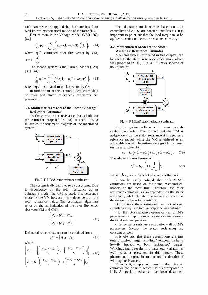
First of them is the Voltage Model (VM) [36],
[44]:
d d
d d
r
s s s s N s
m N
xr x T
t x T t
v
rψ u i i , (14)
where: ψrv– estimated rotor flux vector by VM,
2
1 m
s r
x
x x .
The second system is the Current Model (CM)
[36], [44]:
d 1
( )d
r
m s m
N r
rx j
t T x
i i i
r r rψ i ψ ψ , (15)
where: ψri – estimated rotor flux vector by CM.
In further part of this section a detailed models
of rotor and stator resistances estimators are
presented.
3.1. Mathematical Model of the Rotor Windings’
Resistance Estimator
To the correct rotor resistance (rr) calculation
the estimator proposed in [38] is used. Fig. 3
illustrates the schematic diagram of the mentioned
system.
Fig. 3. F-MRAS rotor resistance estimator
The system is divided into two subsystems. Due
to dependency on the rotor resistance as an
adjustable model the CM is used. The reference
model is the VM because it is independent on the
rotor resistance value. The estimation algorithm
relies on the minimization of the rotor flux error
(between VM and CM):
v i
r r
v i
r r
. (16)
Estimated rotor resistance can be obtained from:
1 2
est
rr Adt A , (17)
where:
1 1
2 2
iir s sr s s
r r
iir s sr s s
r r
x ix iA K
x x
x ix iA K
x x
. (18)
The adaptation mechanism is based on a PI
controller and K1, K2 are constant coefficients. It is
important to point out that the load torque must be
applied to estimate the rotor resistance correctly.
3.2. Mathematical Model of the Stator
Windings’ Resistance Estimator
A second system, presented in this chapter, can
be used to the stator resistance calculation, which
was proposed in [40]. Fig. 4 illustrates scheme of
the estimator.
Fig. 4. F-MRAS stator resistance estimator
In this system voltage and current models
switch their roles. Due to fact that the CM is
independent on the stator resistance it is used as a
reference model, while the VM is utilized as an
adjustable model. The estimation algorithm is based
on the error given by:
v i v i
rs s r r s r re i i . (19)
The adaptation mechanism is:
1
1 ,est
s Prs rs
Irs
r K esT
(20)
where: ,Prs IrsK T - constant positive coefficients.
It can be easily noticed, that both MRAS
estimators are based on the same mathematical
models of the rotor flux. Therefore, the rotor
resistance estimator is also dependent on the stator
resistance, while the stator resistance estimator is
dependent on the rotor resistance.
During tests these estimators weren’t worked
simultaneously, and two assumptions was defined:
• for the rotor resistance estimator - all of IM’s
parameters (except the rotor resistance) are constant
during the drive operation.
• for the stator resistance estimation - all of IM’s
parameters (except the stator resistance) are
constant as well.
It is obvious, that these assumptions are true
only in limited range. Windings’ temperature has a
heavily impact on both resistances’ values.
Windings faults results in a parameter variation as
well (what is presented in this paper). These
phenomena can provoke an inaccurate estimation of
windings resistances. To avoid it, an approach based on the universal
estimator can be used which has been proposed in [44]. A special mechanism has been described,
DIAGNOSTYKA, Vol. 20, No. 2 (2019)
Bednarz SA, Dybkowski M.: Induction motor windings faults detection using flux-error based …
91
which allows to a simultaneous operation of several parameters’ estimators.
4. ALGORITHMS FOR THE INDUCTION
MOTORS ’S WINDINGS FAULTS
DETECTION
Two winding faults detection algorithms are
discussed in the paper. The algorithms cooperate
with estimators of windings resistance. A general
idea of a detection system is illustrated in Fig. 5.
The system is strictly related to the model-based
fault detection approach [17], [18].
Fig. 5. The main idea of the diagnostic system
for IM drive
In the further part of this section a detailed
descriptions of detection procedures are presented.
4.1. The rotor fault detection algorithm
The rotor winding faults detection algorithm
assumes that ruptures of the rotor bar(s) results in a
sharp increase of the estimated rotor resistance.
According to the assumtion, a simple detection
method is proposed which uses a derivative of the
estimated rotor resistance:
d1 0
d
est
r rrIF r THEN ELSEt
, (21)
where:rr - threshold of a rotor windings fault
detection.
When the modulus of the derivative is greater or
equal to the fixed threshold the detector sends a
logical 1 which indicates on a bar damage.
4.2. The stator fault detection algorithm
The stator winding faults detection algorithm is
analogous to the previous one. It assumes, that
ITSC results in a sharp decrease of the estimated
stator resistance. Based on this hypothesis, the
detection method is proposed, which uses a
derivative of the estimated stator resistance:
d1 0
d
est
s rsIF r THEN ELSEt
, (21)
where:rs - threshold of a stator windings fault
detection.
If the modulus of the derivative is equal of
greater to the threshold the detector sends the
logical 1, which indicates on occurring of ITSC.
5. SIMULATION RESULTS
Computer simulation tests were carried out by
MATLAB/Simulink software. Table 1 and Table 2
show the IM’s rated values and parameters,
respectively. Table 1. Induction motor rated values
PN [kW] UN [V] IN [A] nN [rpm] fN [Hz] pb [Hz]
1.1 220/380 5.0/2.9 1400 50 2
Table 2. Induction motor parameters
rs rr xs xr xm
[p.u.] 0.1 0.08 1.8 1.8 1.7
Separate tests for each type of windings faults
were carried out. Each test was performed for the
same conditions: the constant reference speed (ωref
= 0.5ωmN) as well as constant torque load (mL =
0.5mN).
Parameters of the IM’s from table 2 are
presented in the per unit system which detailed
description can be found in [43].
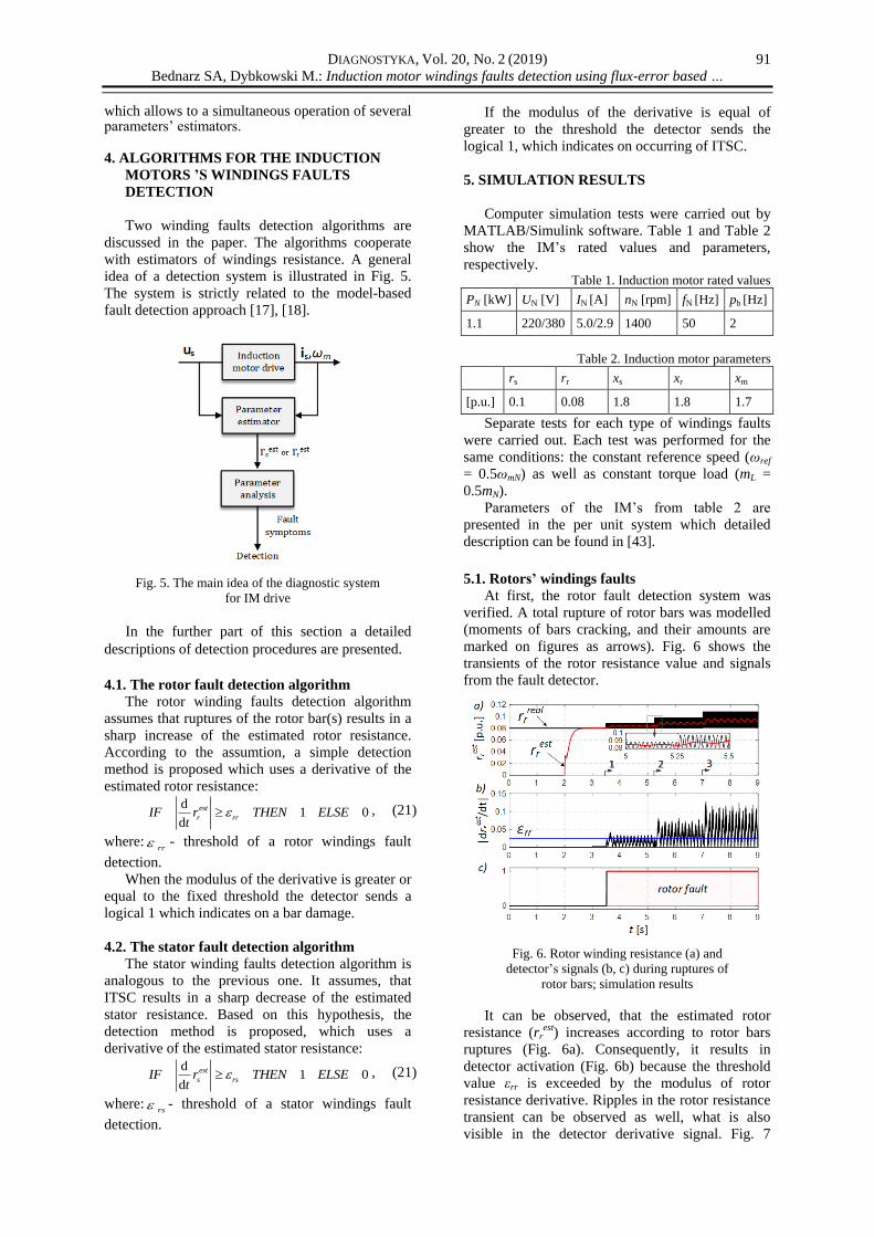
5.1. Rotors’ windings faults
At first, the rotor fault detection system was
verified. A total rupture of rotor bars was modelled
(moments of bars cracking, and their amounts are
marked on figures as arrows). Fig. 6 shows the
transients of the rotor resistance value and signals
from the fault detector.
Fig. 6. Rotor winding resistance (a) and
detector’s signals (b, c) during ruptures of
rotor bars; simulation results
It can be observed, that the estimated rotor
resistance (rrest) increases according to rotor bars
ruptures (Fig. 6a). Consequently, it results in
detector activation (Fig. 6b) because the threshold
value εrr is exceeded by the modulus of rotor
resistance derivative. Ripples in the rotor resistance
transient can be observed as well, what is also
visible in the detector derivative signal. Fig. 7
DIAGNOSTYKA, Vol. 20, No. 2 (2019)
Bednarz SA, Dybkowski M.: Induction motor windings faults detection using flux-error based …
92
presents the transients of the stator current α and
stator current component in axis y.
Fig. 7. Stator current components isα (a) and
isy (b) during ruptures of rotor bars;
simulation results
It is evident that value of the rotor resistance
varies as a result of heating (or cooling) process of
machines’ windings. It may result in incorrect
performance of the fault detector. Therefore, other
tests were carried out where a linear increase of the
rotor resistance was simulated up to 120% of the
nominal value. A low slope of the resistance rise
was assumed because of fact, that thermal time
constant of the machine can reach even several
minutes. Results are shown in Fig. 8 – 9.
Fig. 8. Rotor winding resistances (a) and
detector’s signal (b) during heating process;
simulation results
Fig. 9. Rotor winding resistances (a) and
detector’s signals (b, c) during simultaneous
rotors’ bars ruptures and heating process; simulation results
It can be noticed, that the derivative value
doesn’t exceed assumed threshold – variation of
rotor resistance due to thermal effects is much
slower than due to a bar damage. It can be
concluded that proposed rotor fault detector is
immune to thermal effects occurring in the
machine.
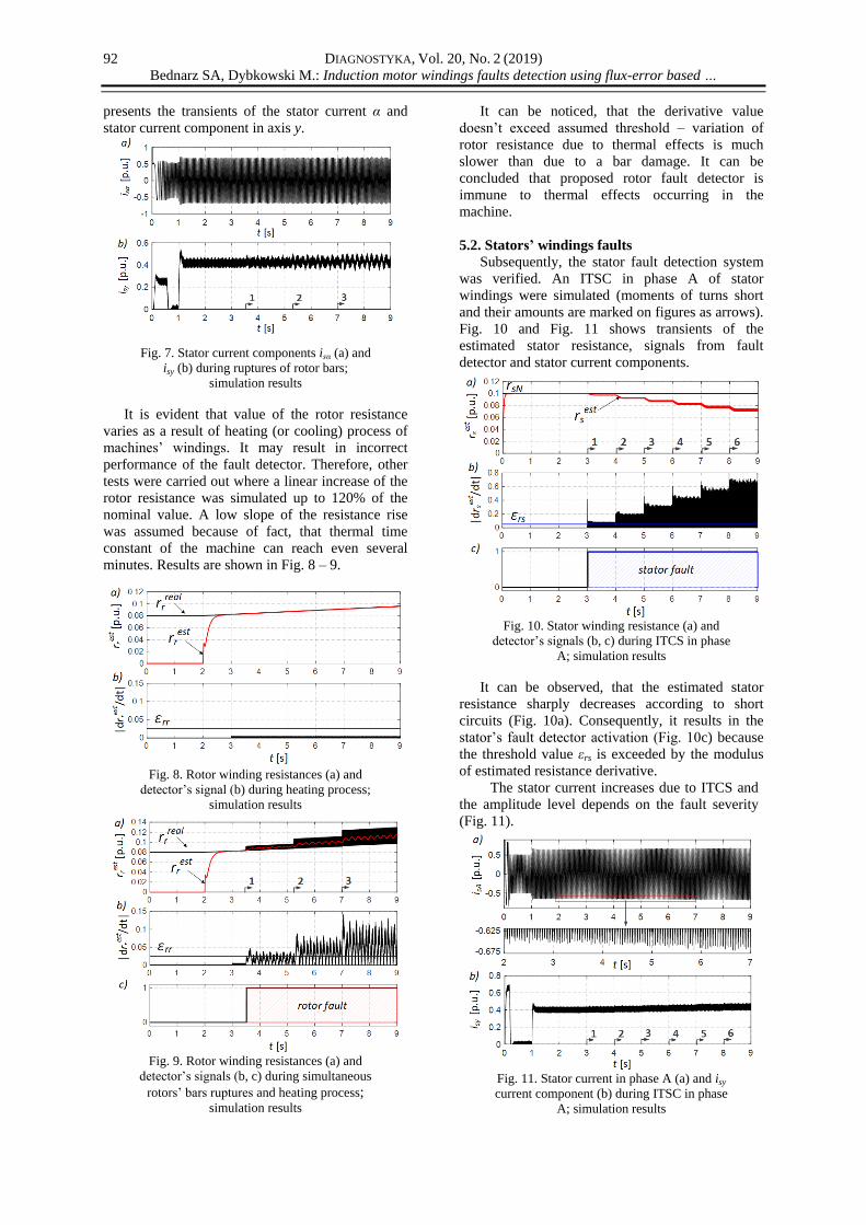
5.2. Stators’ windings faults
Subsequently, the stator fault detection system
was verified. An ITSC in phase A of stator
windings were simulated (moments of turns short
and their amounts are marked on figures as arrows).
Fig. 10 and Fig. 11 shows transients of the
estimated stator resistance, signals from fault
detector and stator current components.
Fig. 10. Stator winding resistance (a) and
detector’s signals (b, c) during ITCS in phase
A; simulation results
It can be observed, that the estimated stator
resistance sharply decreases according to short
circuits (Fig. 10a). Consequently, it results in the
stator’s fault detector activation (Fig. 10c) because
the threshold value εrs is exceeded by the modulus
of estimated resistance derivative.
The stator current increases due to ITCS and
the amplitude level depends on the fault severity
(Fig. 11).
Fig. 11. Stator current in phase A (a) and isy
current component (b) during ITSC in phase
A; simulation results
DIAGNOSTYKA, Vol. 20, No. 2 (2019)
Bednarz SA, Dybkowski M.: Induction motor windings faults detection using flux-error based …
93
Fig. 12. Stator winding resistance (a) and
detector’s signal (b) during simultaneous
ITSC in phase A and heating process;
simulation results
Fig. 13. Stator winding resistance (a) and
detector’s signals (b, c) during simultaneous
ITSC in phase A and heating process;
simulation results
Similarly, to the rotor, a value of the stator
resistance varies due to heating (or cooling) process
of machines’ windings. It can provoke incorrect
performance of the fault detector as well.
Therefore, other tests were performed which were
analogous to the case of the rotor faults (a linear
increase of the stator resistance were simulated up
to 120% of the nominal value).
In Fig. 12 it can be noticed, that derivative value
doesn’t exceed assumed threshold. It can be
concluded, that proposed stator fault detector is also
immune to thermal effects which are occurred in
the machine.
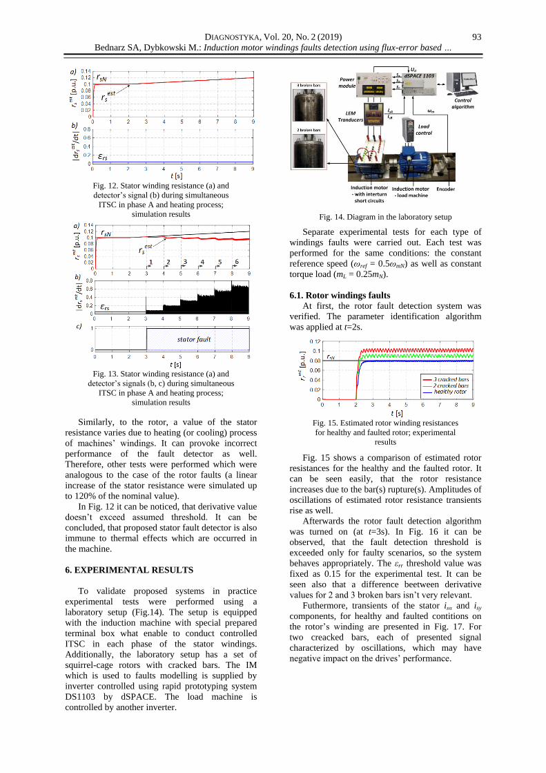
6. EXPERIMENTAL RESULTS
To validate proposed systems in practice
experimental tests were performed using a
laboratory setup (Fig.14). The setup is equipped
with the induction machine with special prepared
terminal box what enable to conduct controlled
ITSC in each phase of the stator windings.
Additionally, the laboratory setup has a set of
squirrel-cage rotors with cracked bars. The IM
which is used to faults modelling is supplied by
inverter controlled using rapid prototyping system
DS1103 by dSPACE. The load machine is
controlled by another inverter.
Fig. 14. Diagram in the laboratory setup
Separate experimental tests for each type of
windings faults were carried out. Each test was
performed for the same conditions: the constant
reference speed (ωref = 0.5ωmN) as well as constant
torque load (mL = 0.25mN).
6.1. Rotor windings faults
At first, the rotor fault detection system was
verified. The parameter identification algorithm
was applied at t=2s.
Fig. 15. Estimated rotor winding resistances
for healthy and faulted rotor; experimental
results
Fig. 15 shows a comparison of estimated rotor
resistances for the healthy and the faulted rotor. It
can be seen easily, that the rotor resistance
increases due to the bar(s) rupture(s). Amplitudes of
oscillations of estimated rotor resistance transients
rise as well.
Afterwards the rotor fault detection algorithm
was turned on (at t=3s). In Fig. 16 it can be
observed, that the fault detection threshold is
exceeded only for faulty scenarios, so the system
behaves appropriately. The εrr threshold value was
fixed as 0.15 for the experimental test. It can be
seen also that a difference beetween derivative
values for 2 and 3 broken bars isn’t very relevant.
Futhermore, transients of the stator isα and isy
components, for healthy and faulted contitions on
the rotor’s winding are presented in Fig. 17. For
two creacked bars, each of presented signal
characterized by oscillations, which may have
negative impact on the drives’ performance.
DIAGNOSTYKA, Vol. 20, No. 2 (2019)
Bednarz SA, Dybkowski M.: Induction motor windings faults detection using flux-error based …
94
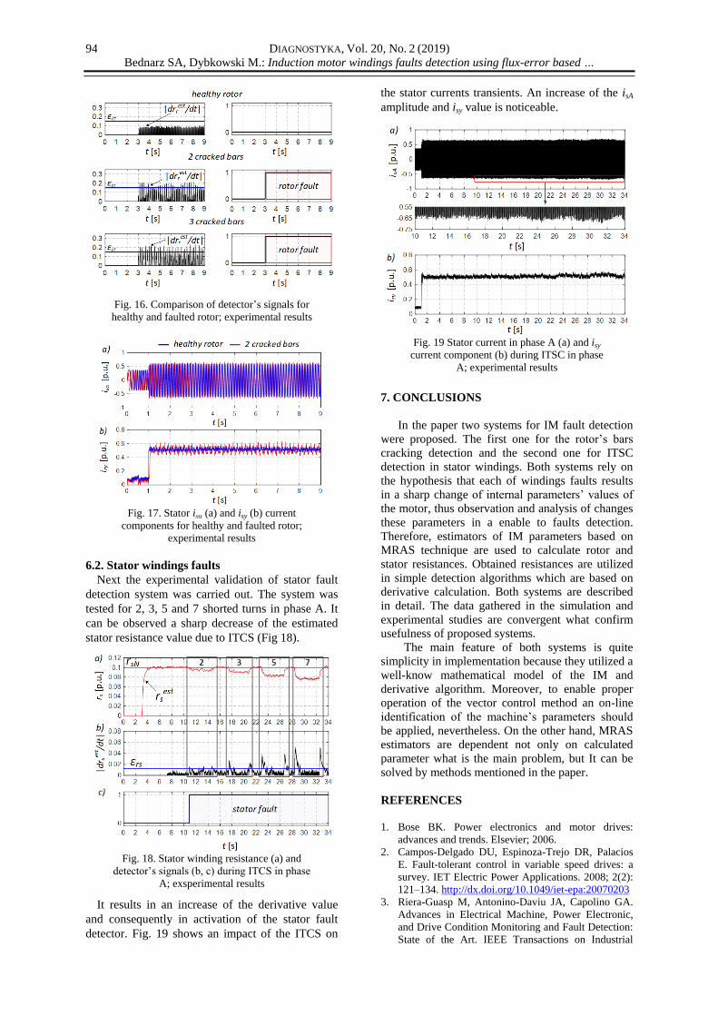
Fig. 16. Comparison of detector’s signals for
healthy and faulted rotor; experimental results
Fig. 17. Stator isα (a) and isy (b) current
components for healthy and faulted rotor;
experimental results
6.2. Stator windings faults
Next the experimental validation of stator fault
detection system was carried out. The system was
tested for 2, 3, 5 and 7 shorted turns in phase A. It
can be observed a sharp decrease of the estimated
stator resistance value due to ITCS (Fig 18).
Fig. 18. Stator winding resistance (a) and
detector’s signals (b, c) during ITCS in phase
A; exsperimental results
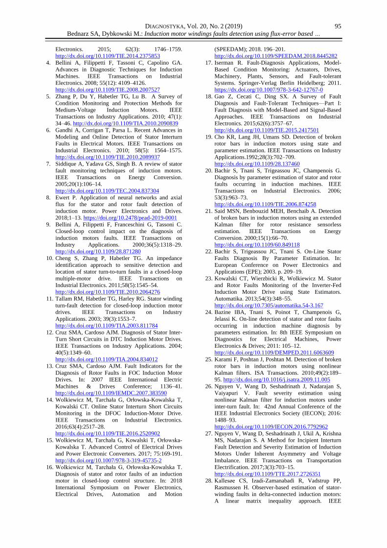
It results in an increase of the derivative value
and consequently in activation of the stator fault
detector. Fig. 19 shows an impact of the ITCS on
the stator currents transients. An increase of the isA
amplitude and isy value is noticeable.
Fig. 19 Stator current in phase A (a) and isy
current component (b) during ITSC in phase
A; experimental results
7. CONCLUSIONS
In the paper two systems for IM fault detection
were proposed. The first one for the rotor’s bars
cracking detection and the second one for ITSC
detection in stator windings. Both systems rely on
the hypothesis that each of windings faults results
in a sharp change of internal parameters’ values of
the motor, thus observation and analysis of changes
these parameters in a enable to faults detection.
Therefore, estimators of IM parameters based on
MRAS technique are used to calculate rotor and
stator resistances. Obtained resistances are utilized
in simple detection algorithms which are based on
derivative calculation. Both systems are described
in detail. The data gathered in the simulation and
experimental studies are convergent what confirm
usefulness of proposed systems.
The main feature of both systems is quite
simplicity in implementation because they utilized a
well-know mathematical model of the IM and
derivative algorithm. Moreover, to enable proper
operation of the vector control method an on-line
identification of the machine’s parameters should
be applied, nevertheless. On the other hand, MRAS
estimators are dependent not only on calculated
parameter what is the main problem, but It can be
solved by methods mentioned in the paper.
REFERENCES
1. Bose BK. Power electronics and motor drives:
advances and trends. Elsevier; 2006.
2. Campos-Delgado DU, Espinoza-Trejo DR, Palacios
E. Fault-tolerant control in variable speed drives: a
survey. IET Electric Power Applications. 2008; 2(2):
121–134. http://dx.doi.org/10.1049/iet-epa:20070203
3. Riera-Guasp M, Antonino-Daviu JA, Capolino GA.
Advances in Electrical Machine, Power Electronic,
and Drive Condition Monitoring and Fault Detection:
State of the Art. IEEE Transactions on Industrial
DIAGNOSTYKA, Vol. 20, No. 2 (2019)
Bednarz SA, Dybkowski M.: Induction motor windings faults detection using flux-error based …
95
Electronics. 2015; 62(3): 1746–1759.
http://dx.doi.org/10.1109/TIE.2014.2375853
4. Bellini A, Filippetti F, Tassoni C, Capolino GA.
Advances in Diagnostic Techniques for Induction
Machines. IEEE Transactions on Industrial
Electronics. 2008; 55(12): 4109–4126.
http://dx.doi.org/10.1109/TIE.2008.2007527
5. Zhang P, Du Y, Habetler TG, Lu B. A Survey of
Condition Monitoring and Protection Methods for
Medium-Voltage Induction Motors. IEEE
Transactions on Industry Applications. 2010; 47(1):
34–46. http://dx.doi.org/10.1109/TIA.2010.2090839
6. Gandhi A, Corrigan T, Parsa L. Recent Advances in
Modeling and Online Detection of Stator Interturn
Faults in Electrical Motors. IEEE Transactions on
Industrial Electronics. 2010; 58(5): 1564–1575.
http://dx.doi.org/10.1109/TIE.2010.2089937
7. Siddique A, Yadava GS, Singh B. A review of stator
fault monitoring techniques of induction motors.
IEEE Transactions on Energy Conversion.
2005;20(1):106–14.
http://dx.doi.org/10.1109/TEC.2004.837304
8. Ewert P. Application of neural networks and axial
flus for the stator and rotor fault detection of
induction motor. Power Electronics and Drives.
2018;1–13. https://doi.org/10.2478/pead-2019-0001
9. Bellini A, Filippetti F, Franceschini G, Tassoni C.
Closed-loop control impact on the diagnosis of
induction motors faults. IEEE Transactions on
Industry Applications. 2000;36(5):1318–29.
http://dx.doi.org/10.1109/28.871280
10. Cheng S, Zhang P, Habetler TG. An impedance
identification approach to sensitive detection and
location of stator turn-to-turn faults in a closed-loop
multiple-motor drive. IEEE Transactions on
Industrial Electronics. 2011;58(5):1545–54.
http://dx.doi.org/10.1109/TIE.2010.2064276
11. Tallam RM, Habetler TG, Harley RG. Stator winding
turn-fault detection for closed-loop induction motor
drives. IEEE Transactions on Industry
Applications. 2003; 39(3):1553–7.
http://dx.doi.org/10.1109/TIA.2003.811784
12. Cruz SMA, Cardoso AJM. Diagnosis of Stator Inter-
Turn Short Circuits in DTC Induction Motor Drives.
IEEE Transactions on Industry Applications. 2004;
40(5):1349–60.
http://dx.doi.org/10.1109/TIA.2004.834012
13. Cruz SMA, Cardoso AJM. Fault Indicators for the
Diagnosis of Rotor Faults in FOC Induction Motor
Drives. In: 2007 IEEE International Electric
Machines & Drives Conference; 1136–41.
http://dx.doi.org/10.1109/IEMDC.2007.383590
14. Wolkiewicz M, Tarchała G, Orłowska-Kowalska T,
Kowalski CT. Online Stator Interturn Short Circuits
Monitoring in the DFOC Induction-Motor Drive.
IEEE Transactions on Industrial Electronics.
2016;63(4):2517–28.
http://dx.doi.org/10.1109/TIE.2016.2520902
15. Wolkiewicz M, Tarchała G, Kowalski T, Orłowska-
Kowalska T. Advanced Control of Electrical Drives
and Power Electronic Converters. 2017; 75:169-191.
http://dx.doi.org/10.1007/978-3-319-45735-2
16. Wolkiewicz M, Tarchała G, Orłowska-Kowalska T.
Diagnosis of stator and rotor faults of an induction
motor in closed-loop control structure. In: 2018
International Symposium on Power Electronics,
Electrical Drives, Automation and Motion
(SPEEDAM); 2018. 196–201.
http://dx.doi.org/10.1109/SPEEDAM.2018.8445282
17. Iserman R. Fault-Diagnosis Applications, Model-
Based Condition Monitoring: Actuators, Drives,
Machinery, Plants, Sensors, and Fault-tolerant
Systems. Springer-Verlag Berlin Heidelberg; 2011.
https://dx.doi.org/10.1007/978-3-642-12767-0
18. Gao Z, Cecati C, Ding SX. A Survey of Fault
Diagnosis and Fault-Tolerant Techniques—Part I:
Fault Diagnosis with Model-Based and Signal-Based
Approaches. IEEE Transactions on Industrial
Electronics. 2015;62(6):3757–67.
http://dx.doi.org/10.1109/TIE.2015.2417501
19. Cho KR, Lang JH, Umans SD. Detection of broken
rotor bars in induction motors using state and
parameter estimation. IEEE Transactions on Industry
Applications.1992;28(3):702–709.
http://dx.doi.org/10.1109/28.137460
20. Bachir S, Tnani S, Trigeassou JC, Champenois G.
Diagnosis by parameter estimation of stator and rotor
faults occurring in induction machines. IEEE
Transactions on Industrial Electronics. 2006;
53(3):963–73.
http://dx.doi.org/10.1109/TIE.2006.874258
21. Said MSN, Benbouzid MEH, Benchaib A. Detection
of broken bars in induction motors using an extended
Kalman filter for rotor resistance sensorless
estimation. IEEE Transactions on Energy
Conversion. 2000;15(1):66–70.
http://dx.doi.org/10.1109/60.849118
22. Bachir S, Trigeassou JC, Tnani S. On-Line Stator
Faults Diagnosis By Parameter Estimation. In:
European Conference on Power Electronics and
Applications (EPE); 2003. p. 209–19.
23. Kowalski CT, Wierzbicki R, Wolkiewicz M. Stator
and Rotor Faults Monitoring of the Inverter-Fed
Induction Motor Drive using State Estimators.
Automatika. 2013;54(3):348–55.
http://dx.doi.org/10.7305/automatika.54-3.167
24. Bazine IBA, Tnani S, Poinot T, Champenois G,
Jelassi K. On-line detection of stator and rotor faults
occurring in induction machine diagnosis by
parameters estimation. In: 8th IEEE Symposium on
Diagnostics for Electrical Machines, Power
Electronics & Drives; 2011: 105–12.
http://dx.doi.org/10.1109/DEMPED.2011.6063609
25. Karami F, Poshtan J, Poshtan M. Detection of broken
rotor bars in induction motors using nonlinear
Kalman filters. ISA Transactions. 2010;49(2):189–
95. http://dx.doi.org/10.1016/j.isatra.2009.11.005
26. Nguyen V, Wang D, Seshadrinath J, Nadarajan S,
Vaiyapuri V. Fault severity estimation using
nonlinear Kalman filter for induction motors under
inter-turn fault. In: 42nd Annual Conference of the
IEEE Industrial Electronics Society (IECON); 2016:
1488–93.
http://dx.doi.org/10.1109/IECON.2016.7792962
27. Nguyen V, Wang D, Seshadrinath J, Ukil A, Krishna
MS, Nadarajan S. A Method for Incipient Interturn
Fault Detection and Severity Estimation of Induction
Motors Under Inherent Asymmetry and Voltage
Imbalance. IEEE Transactions on Transportation
Electrification. 2017;3(3):703–15.
http://dx.doi.org/10.1109/TTE.2017.2726351
28. Kallesøe CS, Izadi-Zamanabadi R, Vadstrup PP,
Rasmussen H. Observer-based estimation of stator-
winding faults in delta-connected induction motors:
A linear matrix inequality approach. IEEE
DIAGNOSTYKA, Vol. 20, No. 2 (2019)
Bednarz SA, Dybkowski M.: Induction motor windings faults detection using flux-error based …
96
Transactions on Industry Applications.
2007;43(4):1022–31.
http://dx.doi.org/10.1109/TIA.2007.900494
29. De Angelo CH, Bossio GR, Giaccone SJ, Valla MI,
Solsona JA, Garcia GO. Online Model-Based Stator-
Fault Detection and Identification in Induction
Motors. IEEE Transactions on Industrial Electronics.
2009;56(11):4671–80.
http://dx.doi.org/10.1109/TIE.2009.2012468
30. Abdallah H, Benatman K. Stator winding inter-turn
short-circuit detection in induction motors by
parameter identification. IET Electric Power
Applications. 2017;11(2):272–88.
http://dx.doi.org/10.1049/iet-epa.2016.0432
31. Chouiref H, Boussaid B, Abdelkrim MN, Aubrun C.
Nonlinear fault tolerant control-based parameter
estimation diagnosis: Application to induction
motors. In: 10th International Multi-Conferences on
Systems, Signals & Devices (SSD); 2013:1–6.
http://dx.doi.org/10.1109/SSD.2013.6564118
32. Treetrong J. Electric Motor Fault Diagnosis Based on
Parameter Estimation Approach Using Genetic
Algorithm. In: International Multi Conference of
Engineers and Computer Scientist (IMECS); 2010.
33. Duan F, Zivanovic R. Condition Monitoring of an
Induction Motor Stator Windings Via Global
Optimization Based on the Hyperbolic Cross Points.
IEEE Transactions on Industrial Electronics.
2015;62(3):1826–34.
http://dx.doi.org/10.1109/TIE.2014.2341563
34. Sellami T, Berriri H, Jelassi S, Mimouni MF. Sliding
mode observer-based fault-detection of inter-turn
short-circuit in induction motor. In: 14th International
Conference on Sciences and Techniques of
Automatic Control & Computer Engineering -
STA’2013; 2013:524–529.
http://dx.doi.org/10.1109/STA.2013.6783182
35. Toliyat HA, Levi E, Raina M. A review of RFO
induction motor parameter estimation techniques.
IEEE Transactions on Energy Conversion.
2003;18(2):271–83.
http://dx.doi.org/10.1109/TEC.2003.811719
36. Syam P, Kumar R, Das S, Chattopadhyay AK.
Review on model reference adaptive system for
sensorless vector control of induction motor drives.
IET Electric Power Applications. 2015;9(7):496–511.
http://dx.doi.org/10.1049/iet-epa.2014.0220
37. Zorgani Y, Jouili M, Koubaa Y. A very low speed
sensorless control induction motor drive with online
rotor resistance using MRAS Scheme. Power
Electronics and Drives. 2018;3(38):171–186.
https://doi.org/10.2478/pead-2018-0021
38. Zorgani YA, Koubaa Y, Boussak M. Sensorless
speed control with MRAS for induction motor drive.
In: XXth International Conference on Electrical
Machines (ICEM); 2012:2259–65.
http://dx.doi.org/10.1109/ICElMach.2012.6350196
39. Bednarz SA, Dybkowski M. On-line detection of the
rotor faults in the induction motor drive using
parameter estimator. In: 2018 International
Symposium on Electrical Machines (SME); 2018. p.
1–5. http://dx.doi.org/10.1109/ISEM.2018.8443020
40. Vasic V, Vukosavic SN, Levi E. A stator resistance
estimation scheme for speed sensorless rotor flux-
oriented induction motor drives. IEEE Trans Energy
Convers. 2003 Dec;18(4):476–83.
http://dx.doi.org/10.1109/TEC.2003.816595
41. Bednarz SA, Dybkowski M, Wolkiewicz M.
Identification of the Stator Faults in the Induction
Motor Drives Using Parameter Estimator. In: IEEE
18th International Power Electronics and Motion
Control Conference (PEMC); 2018. p. 688–93.
http://dx.doi.org/10.1109/EPEPEMC.2018.8521893
42. Pawlak M, Orłowska-Kowalska T. Application of the
simplified two axial model for rotor faults modeling
of the induction motor. Przegląd Elektrotechniczny.
2006;82(10):48–53. Polish.
43. Kaźmierkowski MP, Krishnan R, Blaabjerg F.
Control in power electronics: selected problems.
Elsevier; 2003.
44. Dybkowski M. Universal Speed and Flux Estimator
for Induction Motor. Power Electron
Drives. 2018;3(1):157–69.
http://dx.doi.org/10.2478/pead-2018-0007
Received 2019-02-12
Accepted 2019-04-30
Available online 2019-05-10
Szymon BEDNARZ received
the M.Sc. degree from the
Faculty of Electrical
Engineering, Wrocław
University of Science and
Technology, Wrocław, Poland,
in 2017. Since October 2017 he
has been a PhD student in
electrical engineering in
Department of Electrical
Machines, Drives and
Measurements. His main
research interests include control structures for induction
motor, state variables and parameters estimation,
diagnostics, and fault-tolerant control techniques.
Mateusz DYBKOWSKI received M.S., and Ph. D
degrees in Electrical
Engineering in Wroclaw
University of Technology,
Poland, in 2004, 2008
respectively. In 2014 he
received D.Sc. (Habilitation) on
the Electrical Engineering
Faculty of the Wroclaw
University of Technology.
Since 2015 he is a professor in the Department of
Electrical Engineering. His major research fields are the
sensorless drives system, fault tolerant control systems,
state and variable estimation, traction drives systems, e-
mobility and Power Electronics in Electrical Drives. He
is a Deputy Editor-in-Chief in Power Electronics and
Drives journal and head of the Laboratory of Industrial
Automation.


![Overview of the Rectangular Wire Windings AC …2019/06/25 · wire windings and the stranded windings, where the welding technic has been involved [4]. Thus, it is necessary to reasonably](https://img.pdfslide.us/doc/110x75/5ea4411122769e408b4b5e35/overview-of-the-rectangular-wire-windings-ac-20190625-wire-windings-and-the.jpg)