Embed Size (px)
Citation preview
Induction and Inductance Chapter 30
Magnetic Flux
Gauss Like AB d
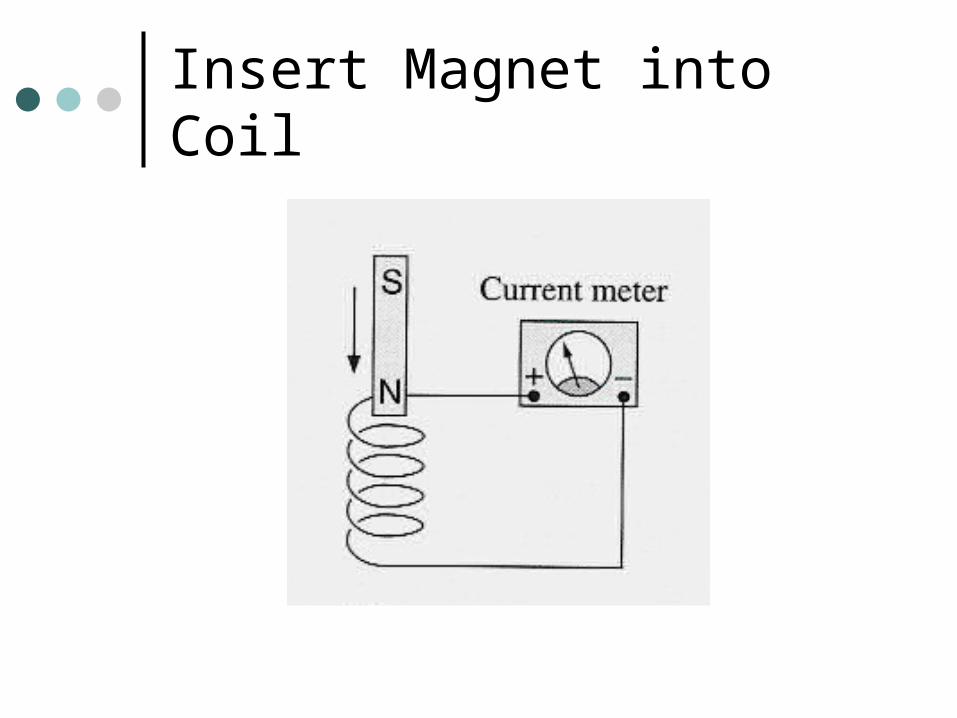
Insert Magnet into Coil
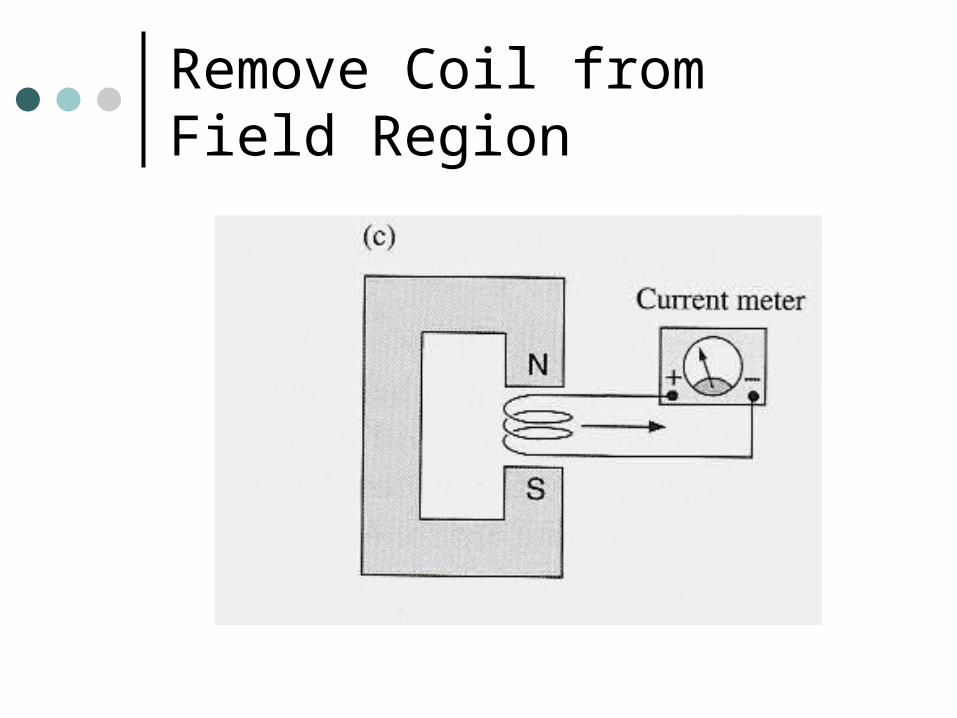
Remove Coil from Field Region
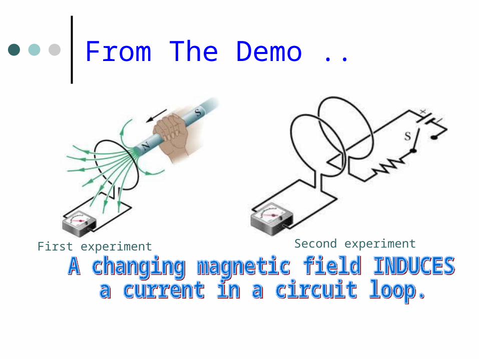
From The Demo ..
First experiment Second experiment
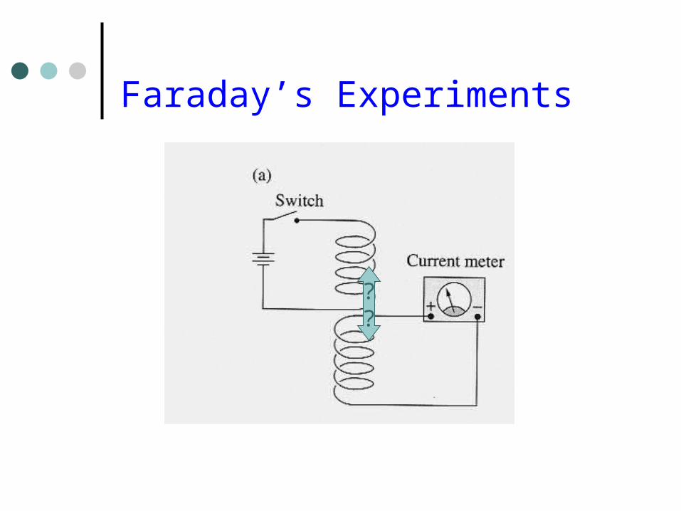
Faraday’s Experiments
??
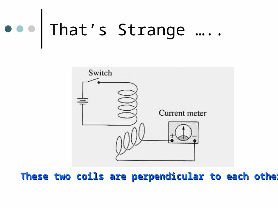
That’s Strange …..
These two coils are perpendicular to each otherThese two coils are perpendicular to each other
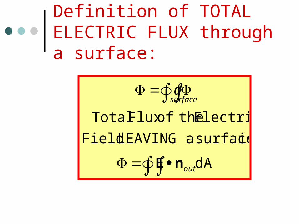
Definition of TOTAL ELECTRIC FLUX through a surface:
dA
is surface aLEAVING Field
Electric theofFlux Total
out
surfaced
nE
Magnetic Flux:
THINK OFMAGNETIC FLUX
as the“AMOUNT of Magnetism”
passing through a surface.
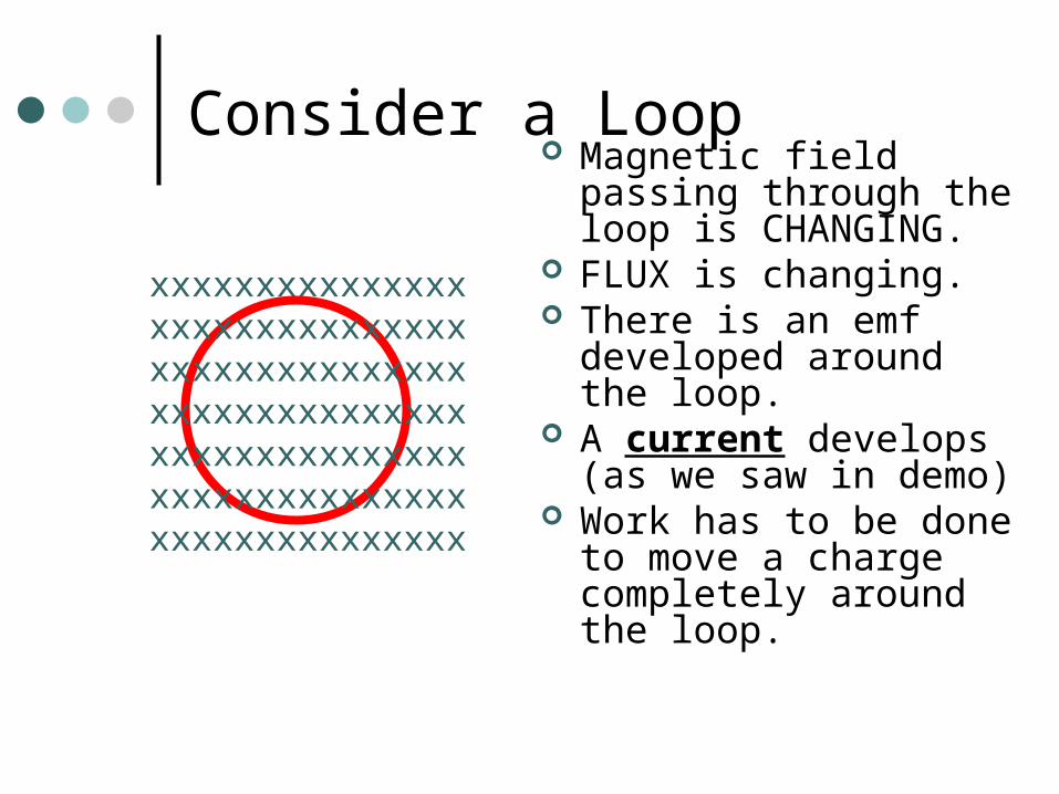
Consider a Loop Magnetic field passing
through the loop is CHANGING.
FLUX is changing. There is an emf
developed around the loop.
A current develops (as we saw in demo)
Work has to be done to move a charge completely around the loop.
xxxxxxxxxxxxxxxxxxxxxxxxxxxxxxxxxxxxxxxxxxxxxxxxxxxxxxxxxxxxxxxxxxxxxxxxxxxxxxxxxxxxxxxxxxxxxxxxxxxxxxxxx
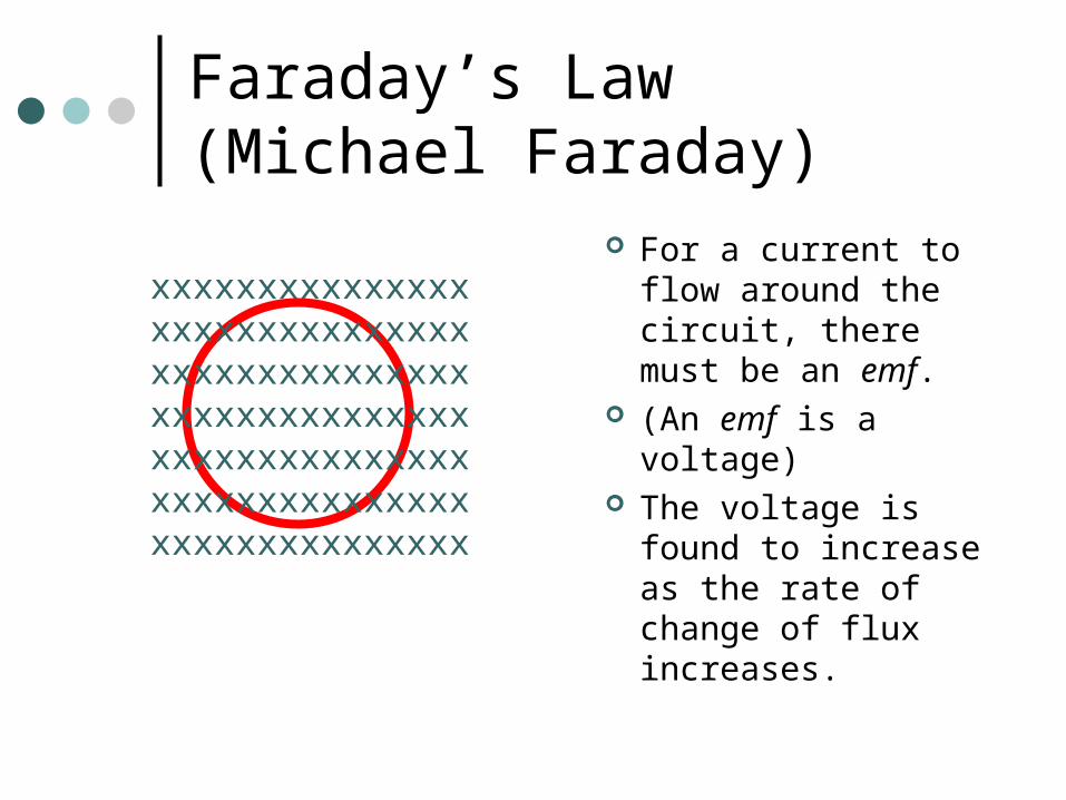
Faraday’s Law (Michael Faraday)
For a current to flow around the circuit, there must be an emf.
(An emf is a voltage) The voltage is found
to increase as the rate of change of flux increases.
xxxxxxxxxxxxxxxxxxxxxxxxxxxxxxxxxxxxxxxxxxxxxxxxxxxxxxxxxxxxxxxxxxxxxxxxxxxxxxxxxxxxxxxxxxxxxxxxxxxxxxxxx
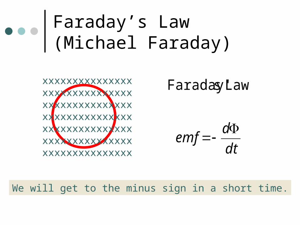
Faraday’s Law (Michael Faraday)
xxxxxxxxxxxxxxxxxxxxxxxxxxxxxxxxxxxxxxxxxxxxxxxxxxxxxxxxxxxxxxxxxxxxxxxxxxxxxxxxxxxxxxxxxxxxxxxxxxxxxxxxx dt
demf
Law sFaraday'
We will get to the minus sign in a short time.
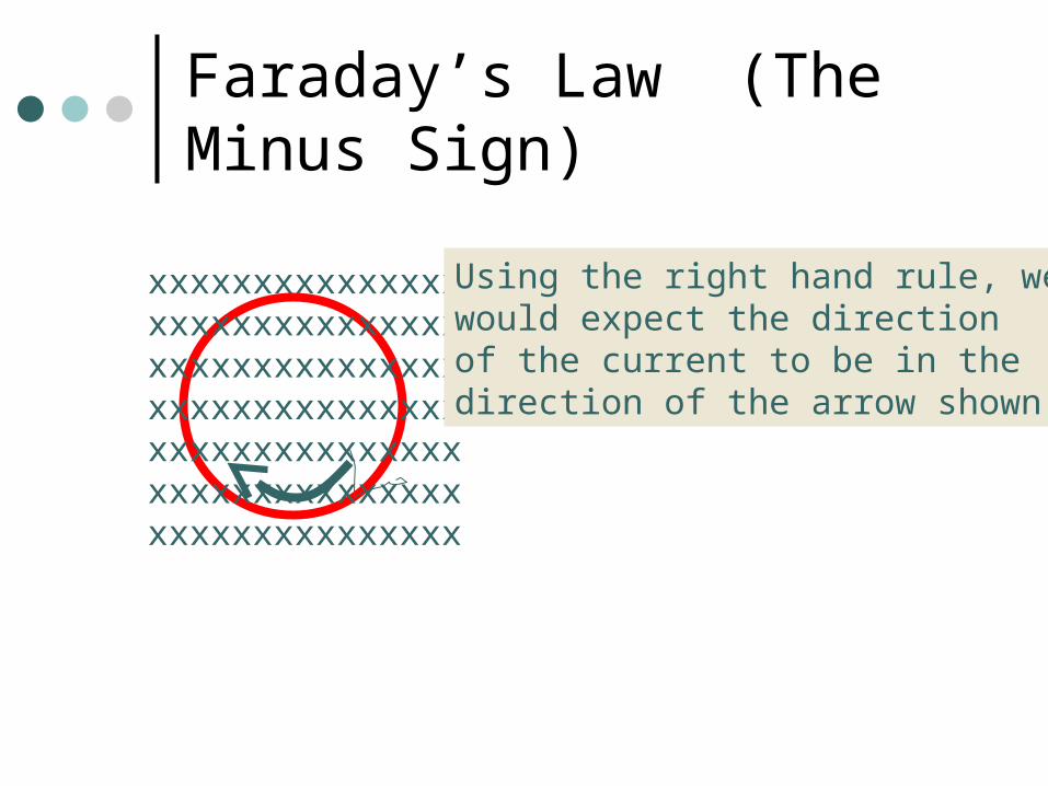
Faraday’s Law (The Minus Sign)
xxxxxxxxxxxxxxxxxxxxxxxxxxxxxxxxxxxxxxxxxxxxxxxxxxxxxxxxxxxxxxxxxxxxxxxxxxxxxxxxxxxxxxxxxxxxxxxxxxxxxxxxx
Using the right hand rule, wewould expect the directionof the current to be in thedirection of the arrow shown.
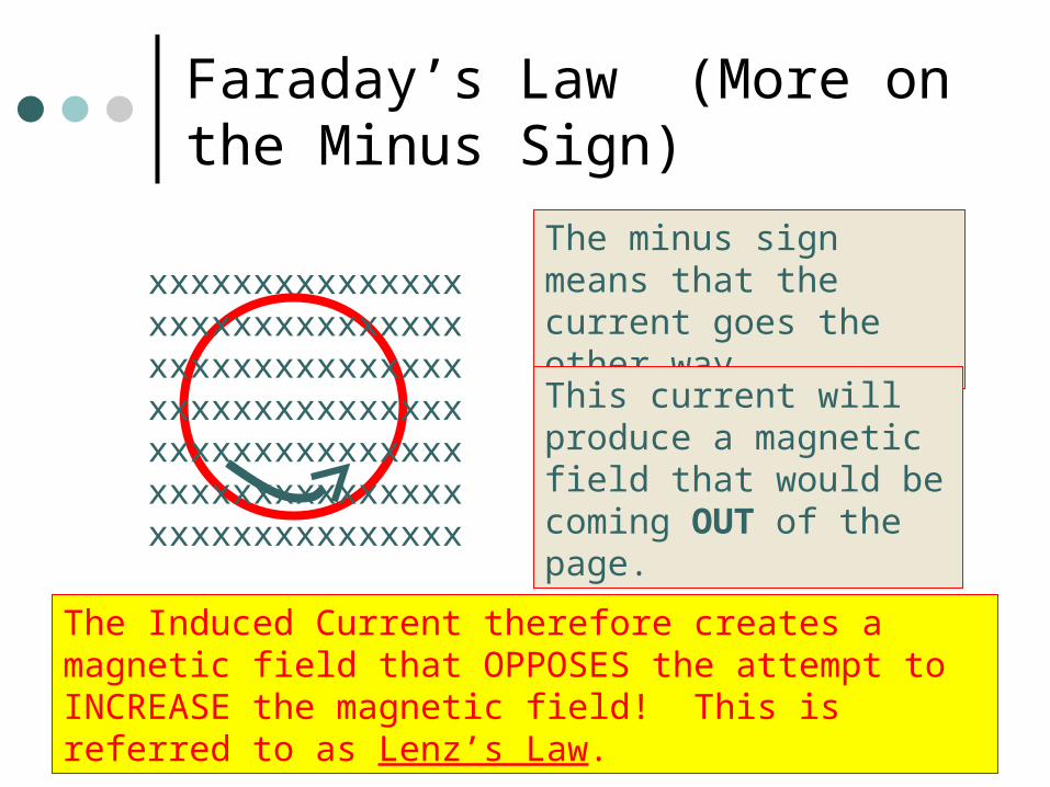
Faraday’s Law (More on the Minus Sign)
xxxxxxxxxxxxxxxxxxxxxxxxxxxxxxxxxxxxxxxxxxxxxxxxxxxxxxxxxxxxxxxxxxxxxxxxxxxxxxxxxxxxxxxxxxxxxxxxxxxxxxxxx
The minus sign means that the current goes the other way.
This current will produce a magnetic field that would be coming OUT of the page.
The Induced Current therefore creates a magnetic field that OPPOSES the attempt to INCREASE the magnetic field! This is referred to as Lenz’s Law.
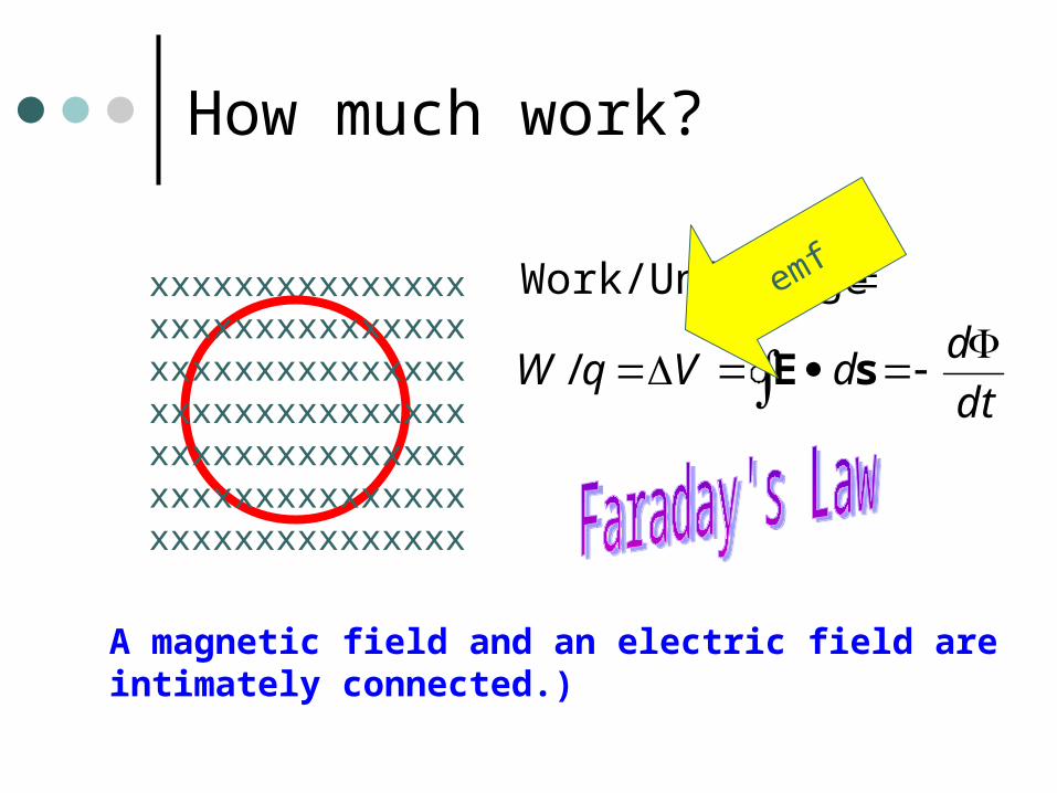
How much work?
xxxxxxxxxxxxxxxxxxxxxxxxxxxxxxxxxxxxxxxxxxxxxxxxxxxxxxxxxxxxxxxxxxxxxxxxxxxxxxxxxxxxxxxxxxxxxxxxxxxxxxxxx
dt
ddVqW
sE/
ChargeWork/Unit
A magnetic field and an electric field areintimately connected.)
emf
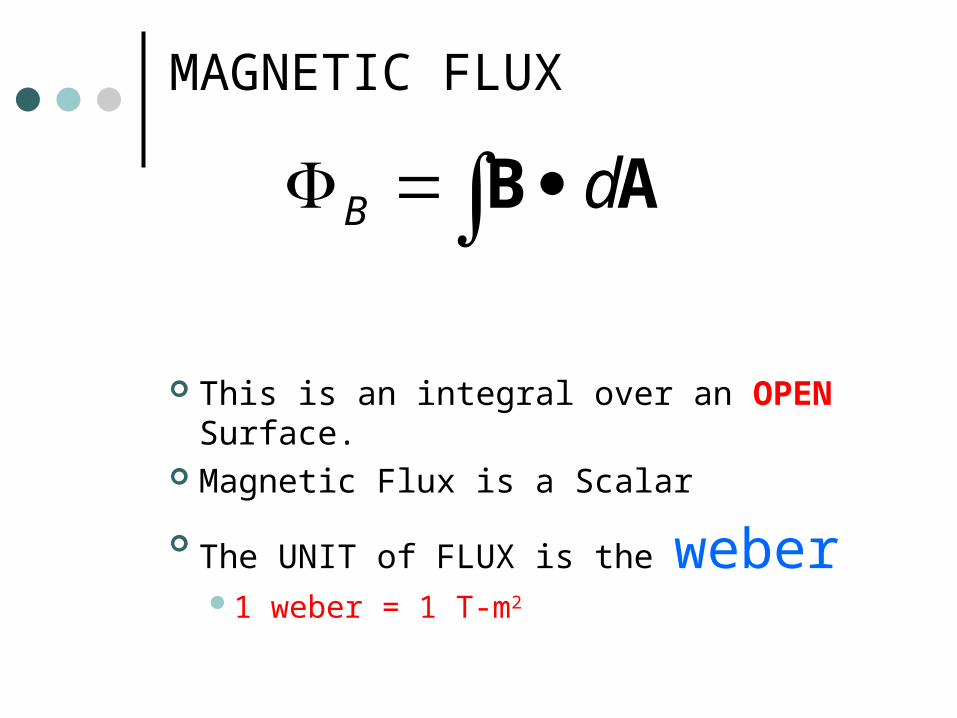
MAGNETIC FLUX
This is an integral over an OPEN Surface.
Magnetic Flux is a Scalar
The UNIT of FLUX is the weber1 weber = 1 T-m2
AB dB
We finally stated
dt
demf
FARADAY’s LAW
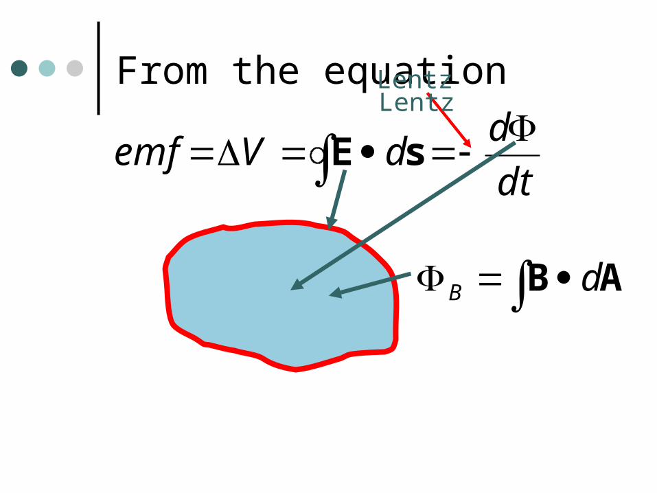
From the equation
dt
ddVemf
sE
AB dB
LentzLentz
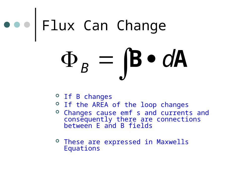
Flux Can Change
If B changes If the AREA of the loop changes Changes cause emf s and currents and
consequently there are connections between E and B fields
These are expressed in Maxwells Equations
AB dB
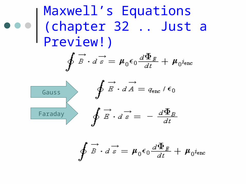
Maxwell’s Equations(chapter 32 .. Just a Preview!)
Gauss
Faraday
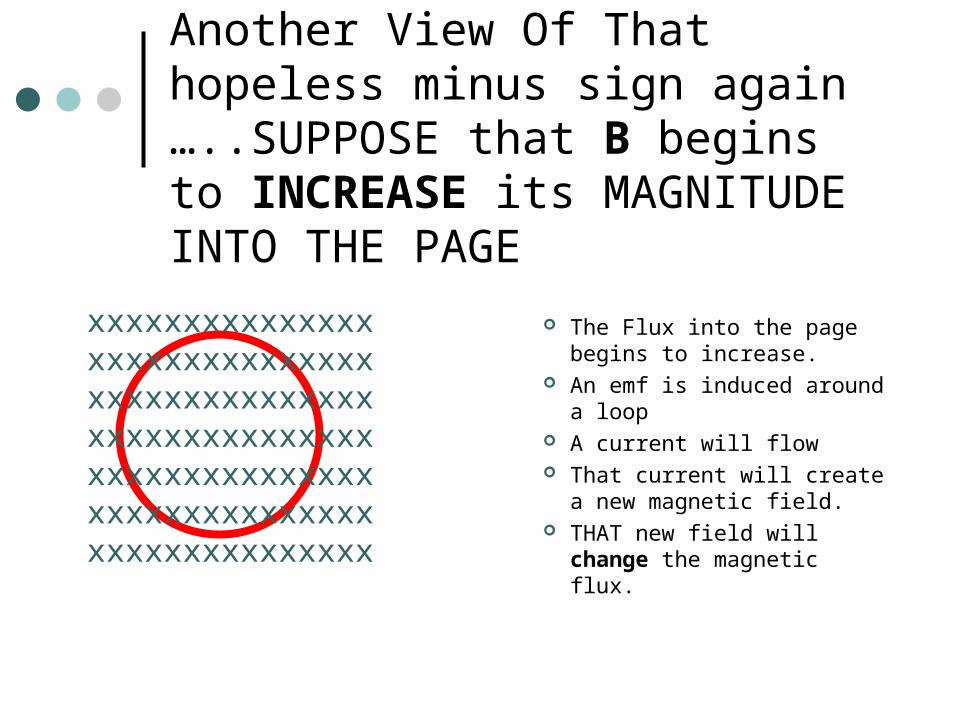
Another View Of That hopeless minus sign again …..SUPPOSE that B begins to INCREASE its MAGNITUDE INTO THE PAGE
The Flux into the page begins to increase.
An emf is induced around a loop
A current will flow That current will create a
new magnetic field. THAT new field will
change the magnetic flux.
xxxxxxxxxxxxxxxxxxxxxxxxxxxxxxxxxxxxxxxxxxxxxxxxxxxxxxxxxxxxxxxxxxxxxxxxxxxxxxxxxxxxxxxxxxxxxxxxxxxxxxxxx
Lenz’s Law
Induced Magnetic Fields always FIGHT to stop what you are trying to do!
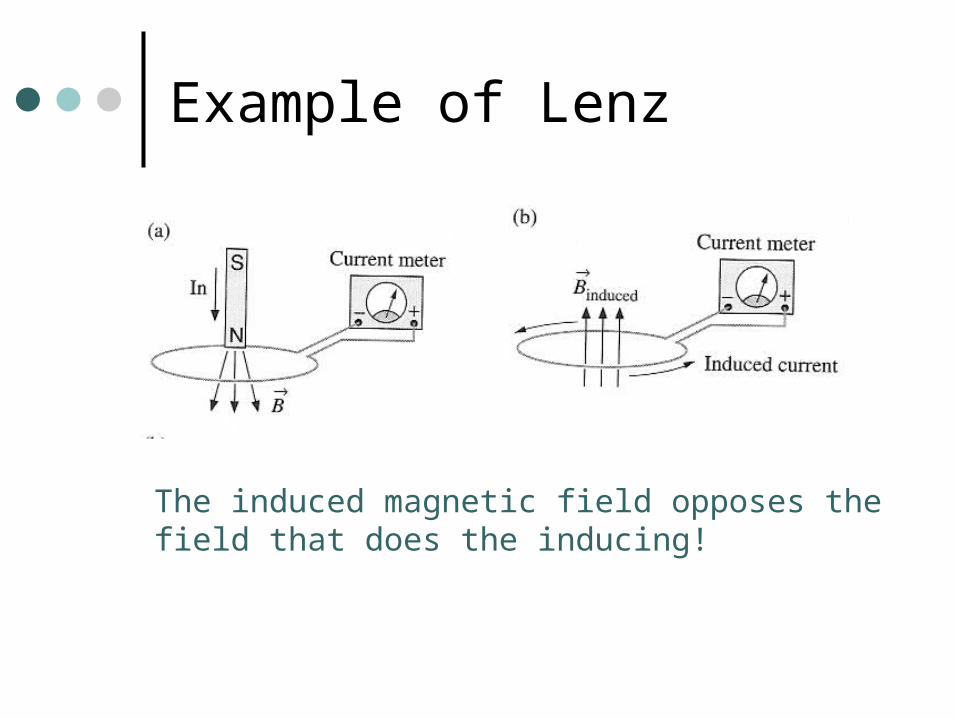
Example of Lenz
The induced magnetic field opposes thefield that does the inducing!
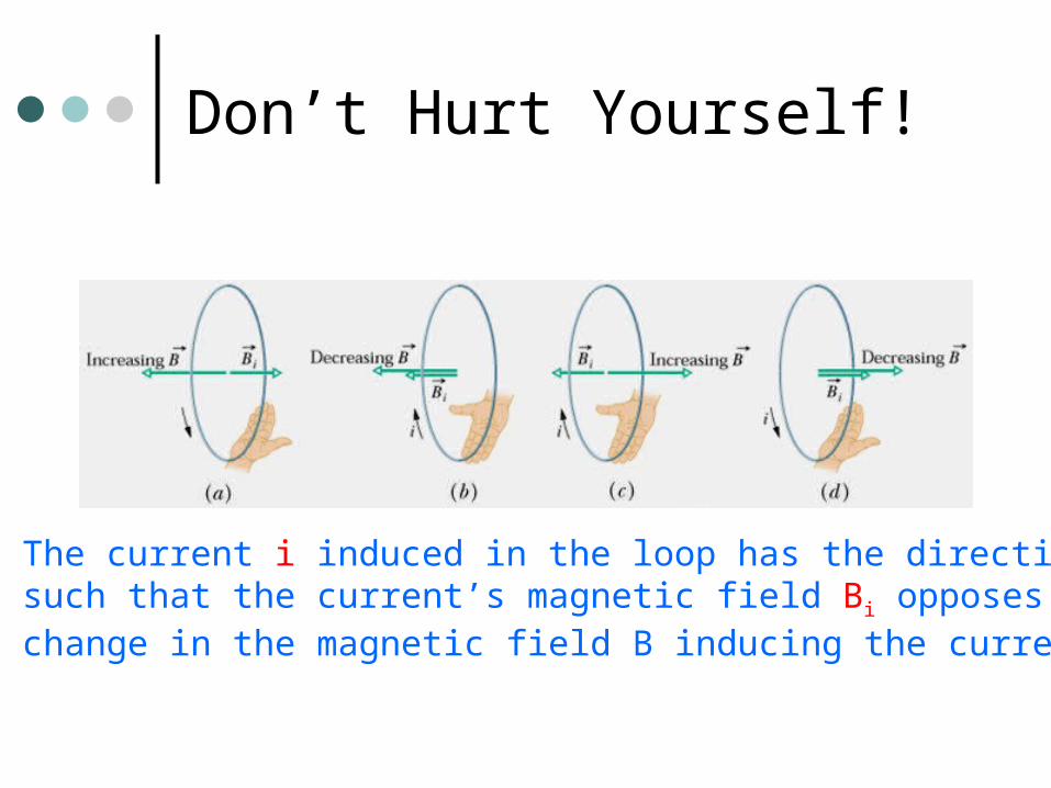
Don’t Hurt Yourself!
The current i induced in the loop has the directionsuch that the current’s magnetic field Bi opposes thechange in the magnetic field B inducing the current.
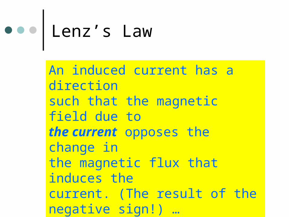
Lenz’s Law
An induced current has a directionsuch that the magnetic field due tothe current opposes the change in the magnetic flux that induces thecurrent. (The result of the negative sign!) …
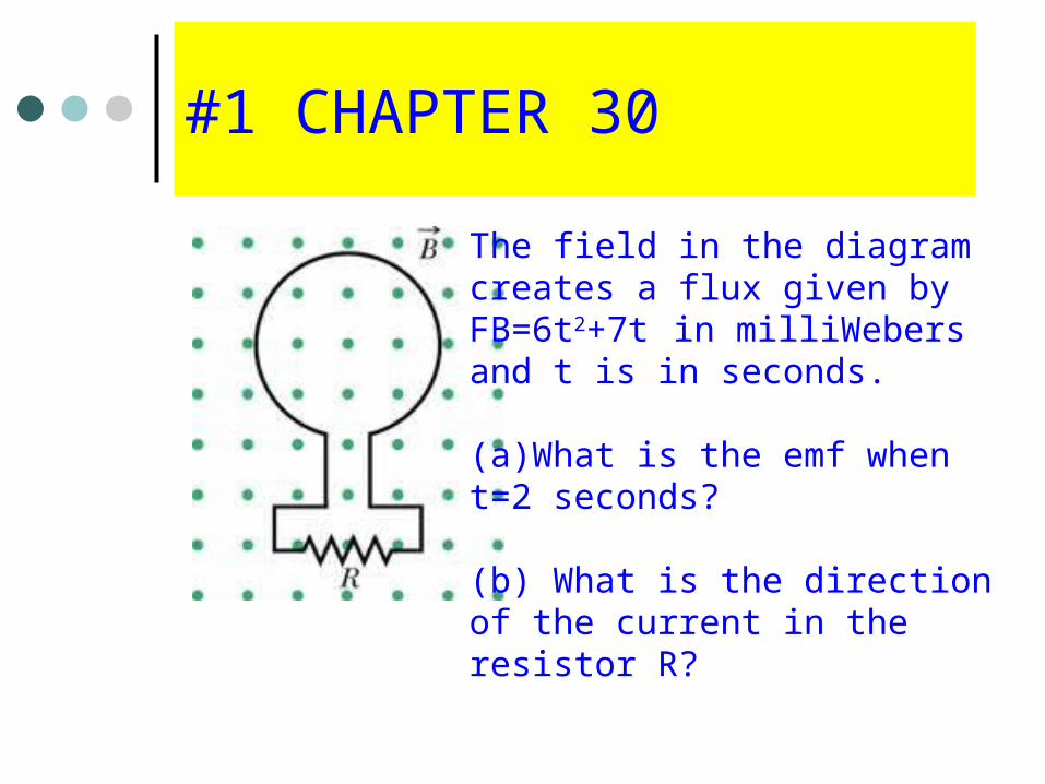
#1 CHAPTER 30
The field in the diagramcreates a flux given byFB=6t2+7t in milliWebersand t is in seconds.
(a)What is the emf whent=2 seconds?
(b) What is the directionof the current in the resistor R?
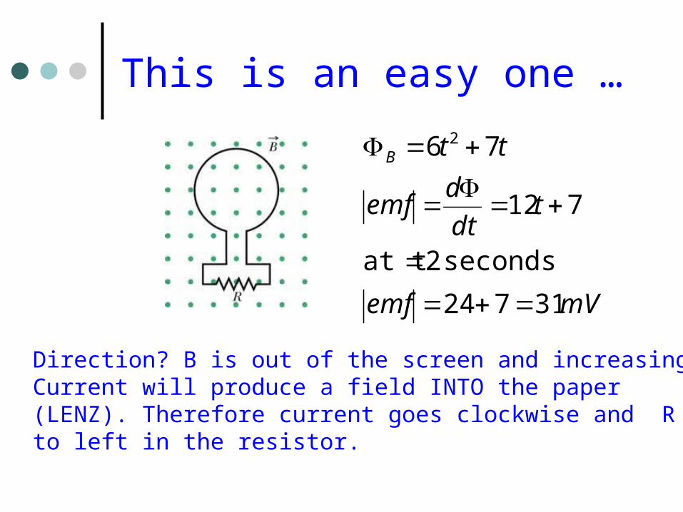
This is an easy one …
mVemf
tdt
demf
ttB
31724
seconds 2at t
712
76 2
Direction? B is out of the screen and increasing.Current will produce a field INTO the paper (LENZ). Therefore current goes clockwise and R to left in the resistor.
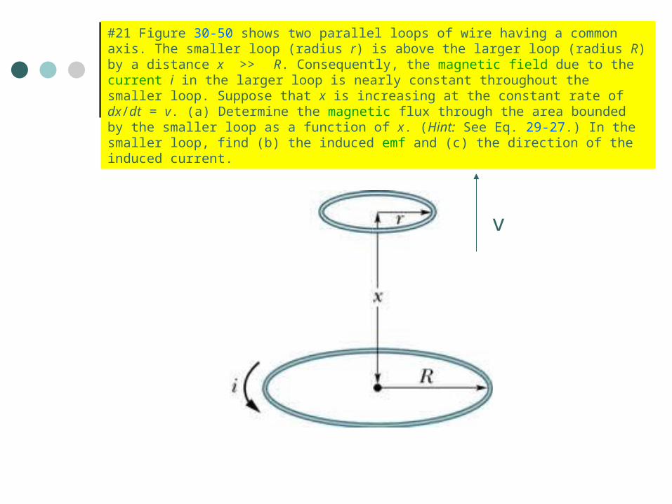
#21 Figure 30-50 shows two parallel loops of wire having a common axis. The smaller loop (radius r) is above the larger loop (radius R) by a distance x >> R. Consequently, the magnetic field due to the current i in the larger loop is nearly constant throughout the smaller loop. Suppose that x is increasing at the constant rate of dx/dt = v. (a) Determine the magnetic flux through the area bounded by the smaller loop as a function of x. (Hint: See Eq. 29-27.) In the smaller loop, find (b) the induced emf and (c) the direction of the induced current.
v
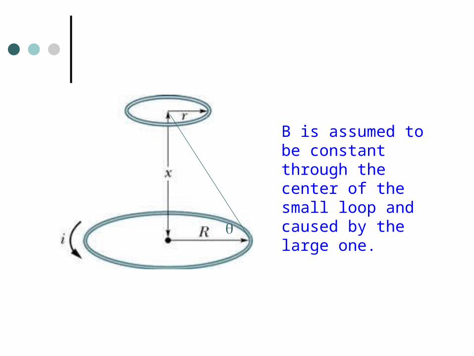
B is assumed to be constant through the center of the small loop and caused by the large one.
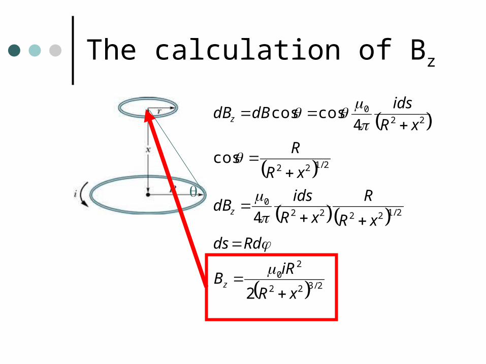
The calculation of Bz
2/322
20
2/122220
2/122
220
2
4
cos
4coscos
xR
iRB
Rdds
xR
R
xR
idsdB
xR
R
xR
idsdBdB
z
z
z
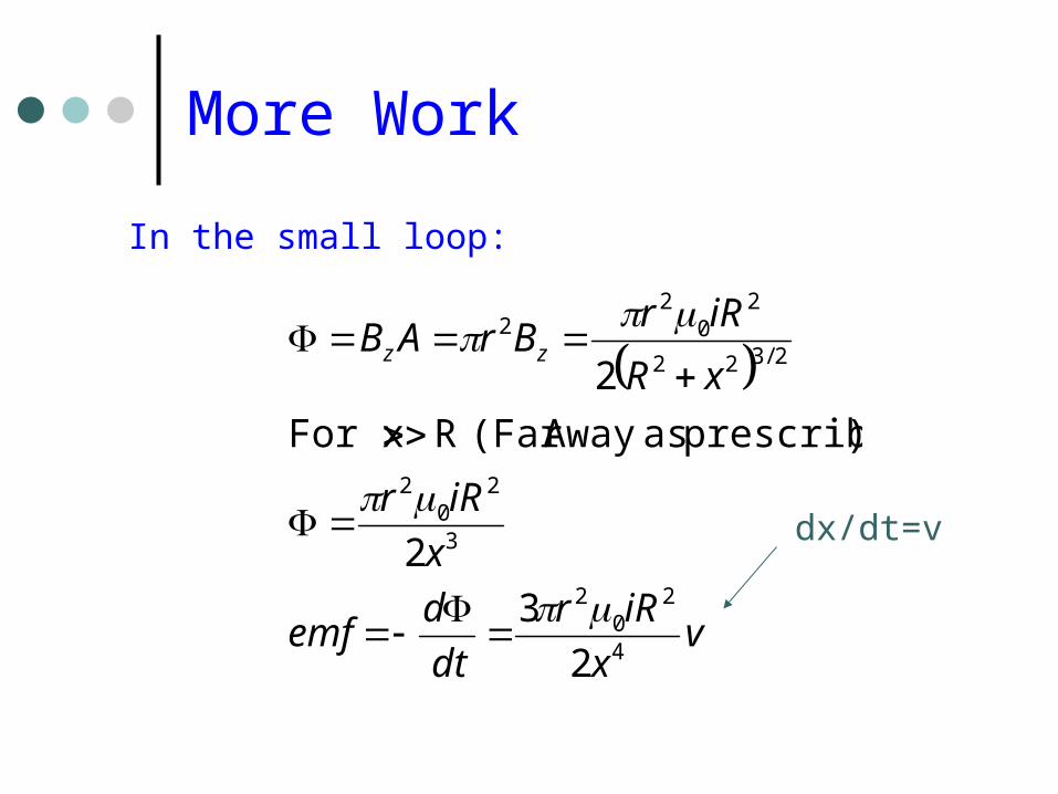
More Work
In the small loop:
vx
iRr
dt
demf
x
iRr
xR
iRrBrAB zz
4
20
2
3
20
2
2/322
20
22
2
3
2
)prescribed asAway (Far RFor x
2
dx/dt=v
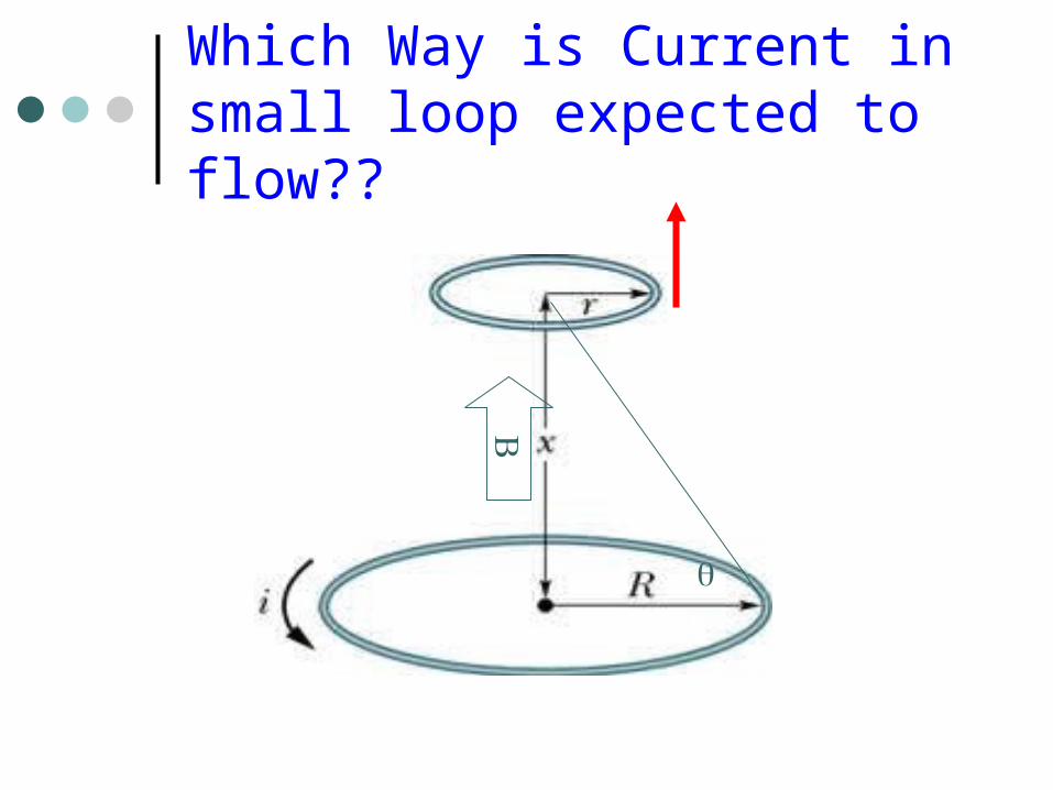
Which Way is Current in small loop expected to flow??
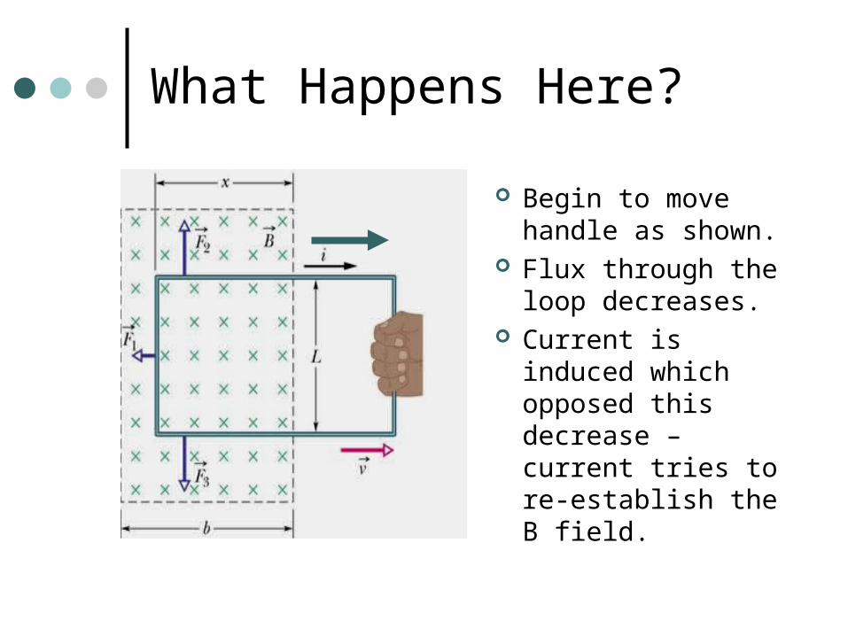
What Happens Here?
Begin to move handle as shown.
Flux through the loop decreases.
Current is induced which opposed this decrease – current tries to re-establish the B field.
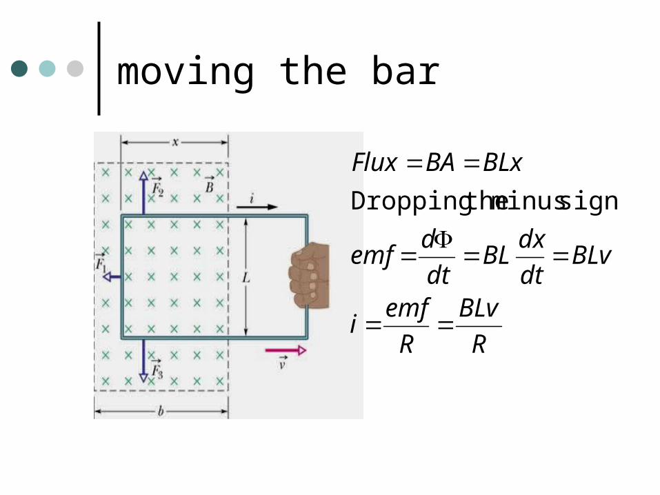
moving the bar
R
BLv
R
emfi
BLvdt
dxBL
dt
demf
BLxBAFlux
sign... minus theDropping
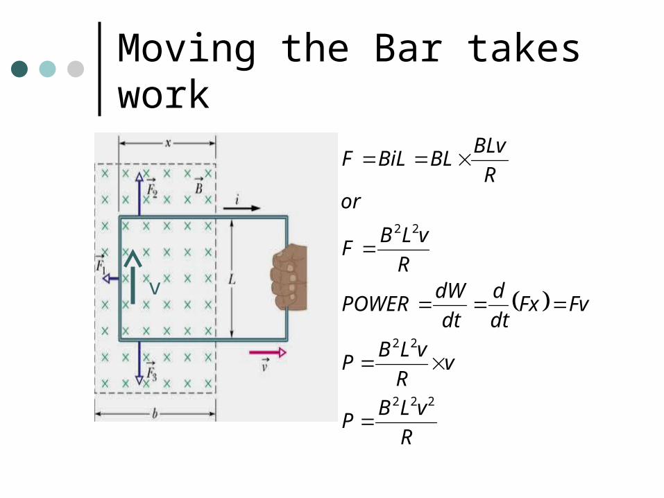
Moving the Bar takes work
v
R
vLBP
vR
vLBP
FvFxdt
d
dt
dWPOWER
R
vLBF
orR
BLvBLBiLF
222
22
22
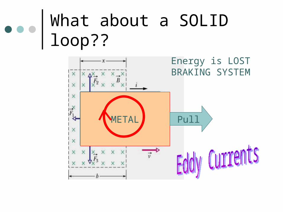
What about a SOLID loop??
METAL Pull
Energy is LOSTBRAKING SYSTEM
Back to Circuits for a bit ….
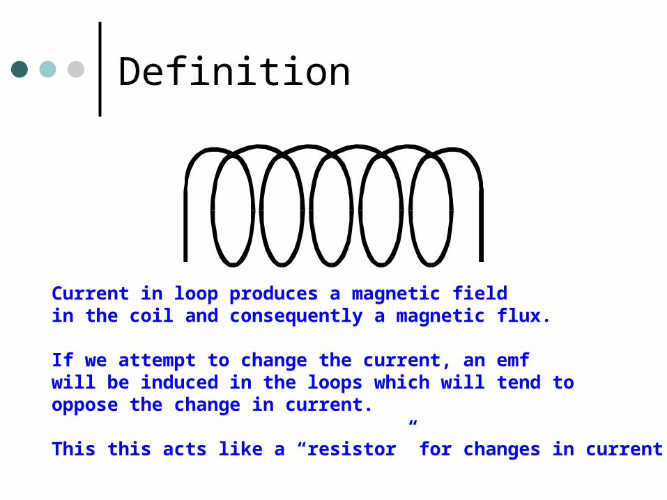
Definition
Current in loop produces a magnetic fieldin the coil and consequently a magnetic flux.
If we attempt to change the current, an emfwill be induced in the loops which will tend tooppose the change in current.
This this acts like a “resistor” for changes in current!
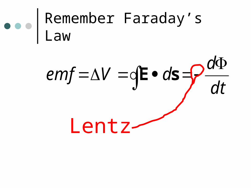
Remember Faraday’s Law
dt
ddVemf
sE
Lentz
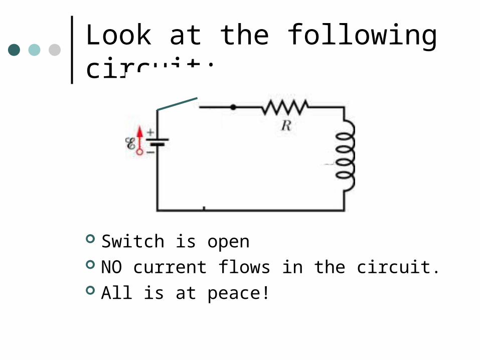
Look at the following circuit:
Switch is open NO current flows in the circuit. All is at peace!
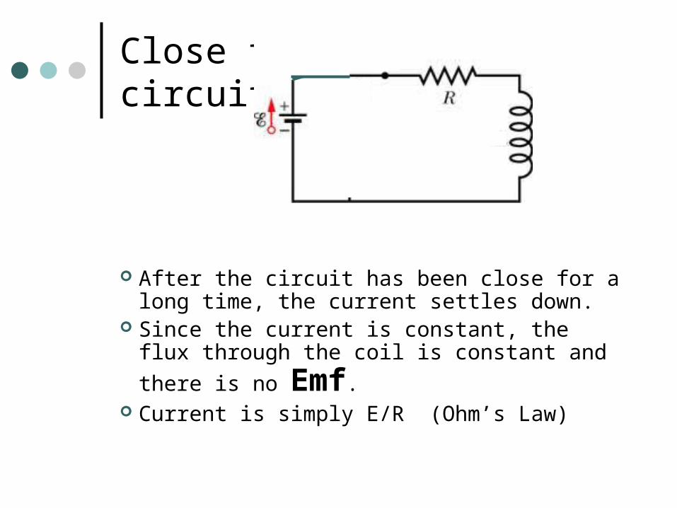
Close the circuit…
After the circuit has been close for a long time, the current settles down.
Since the current is constant, the flux through
the coil is constant and there is no Emf. Current is simply E/R (Ohm’s Law)
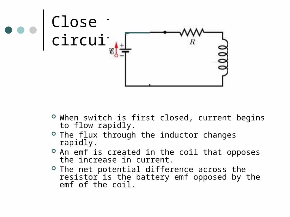
Close the circuit…
When switch is first closed, current begins to flow rapidly.
The flux through the inductor changes rapidly. An emf is created in the coil that opposes the
increase in current. The net potential difference across the resistor is
the battery emf opposed by the emf of the coil.
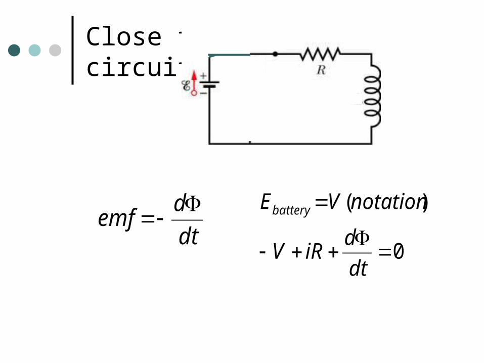
Close the circuit…
dt
demf
0
)(
dt
diRV
notationVEbattery
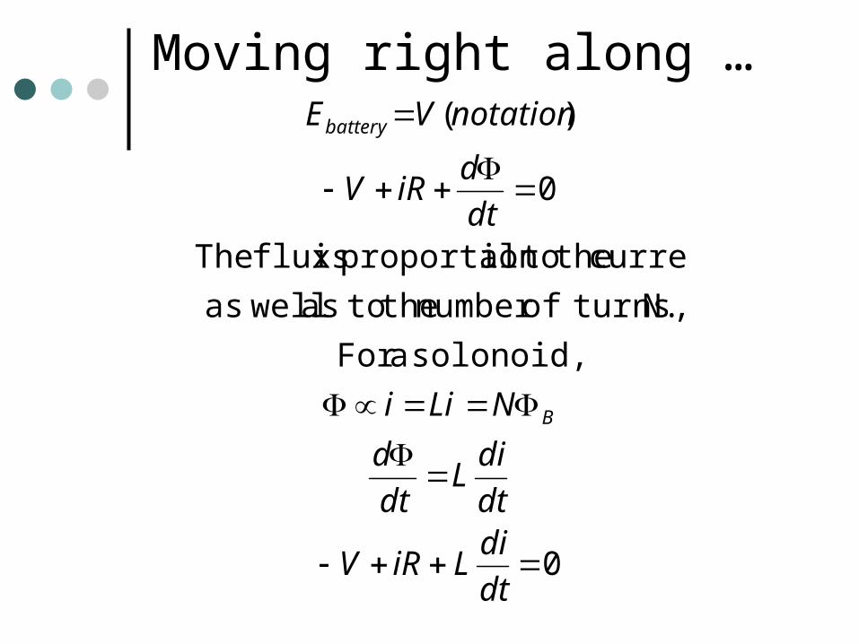
Moving right along …
0
solonoid, aFor
N. turns,ofnumber the toas wellas
current the toalproportion isflux The
0
)(
dt
diLiRV
dt
diL
dt
d
NLii
dt
diRV
notationVE
B
battery
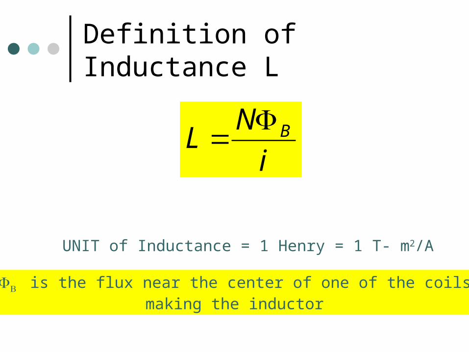
Definition of Inductance L
i
NL B
UNIT of Inductance = 1 Henry = 1 T- m2/A
is the flux near the center of one of the coilsmaking the inductor
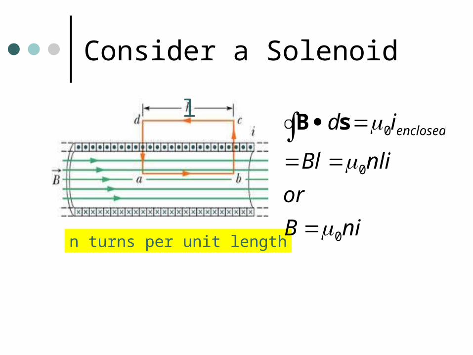
Consider a Solenoid
n turns per unit lengthniB
or
nliBl
id enclosed
0
0
0
sBl
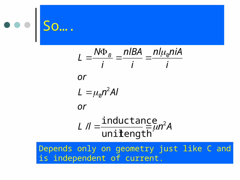
So….
AnlL
or
AlnL
ori
niAnl
i
nlBA
i
NL B
2
20
0
lengthunit
inductance/
Depends only on geometry just like C andis independent of current.
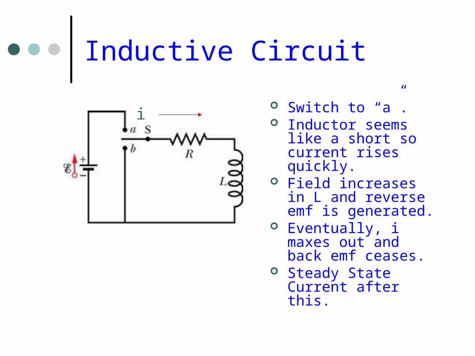
Inductive Circuit
Switch to “a”. Inductor seems like
a short so current rises quickly.
Field increases in L and reverse emf is generated.
Eventually, i maxes out and back emf ceases.
Steady State Current after this.
i
THE BIG INDUCTION
As we begin to increase the current in the coil
The current in the first coil produces a magnetic field in the second coil
Which tries to create a current which will reduce the field it is experiences
And so resists the increase in current.
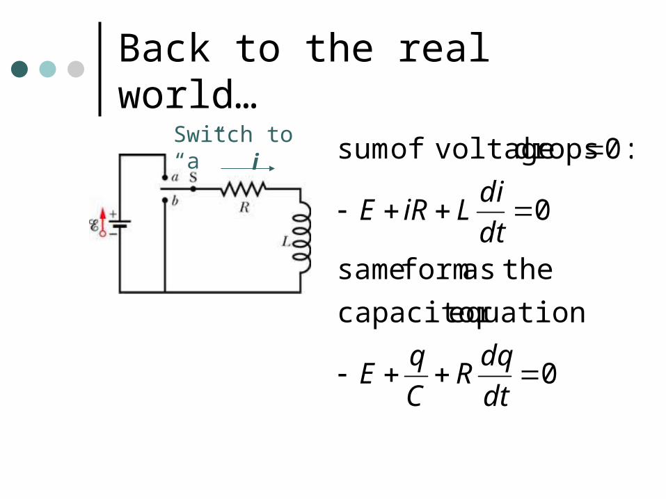
Back to the real world…
i
0
equationcapacitor
theas form same
0
:0 drops voltageof sum
dt
dqR
C
qE
dt
diLiRE
Switch to “a”
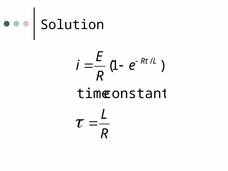
Solution
R
L
eR
Ei LRt
constant time
)1( /
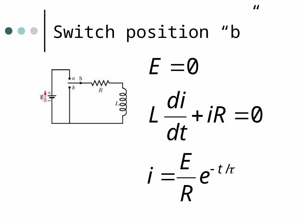
Switch position “b”
/
0
0
teR
Ei
iRdt
diL
E
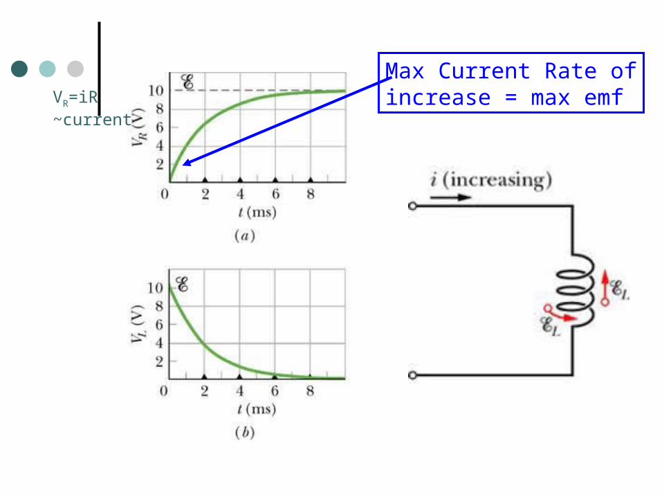
Max Current Rate ofincrease = max emfVR=iR
~current
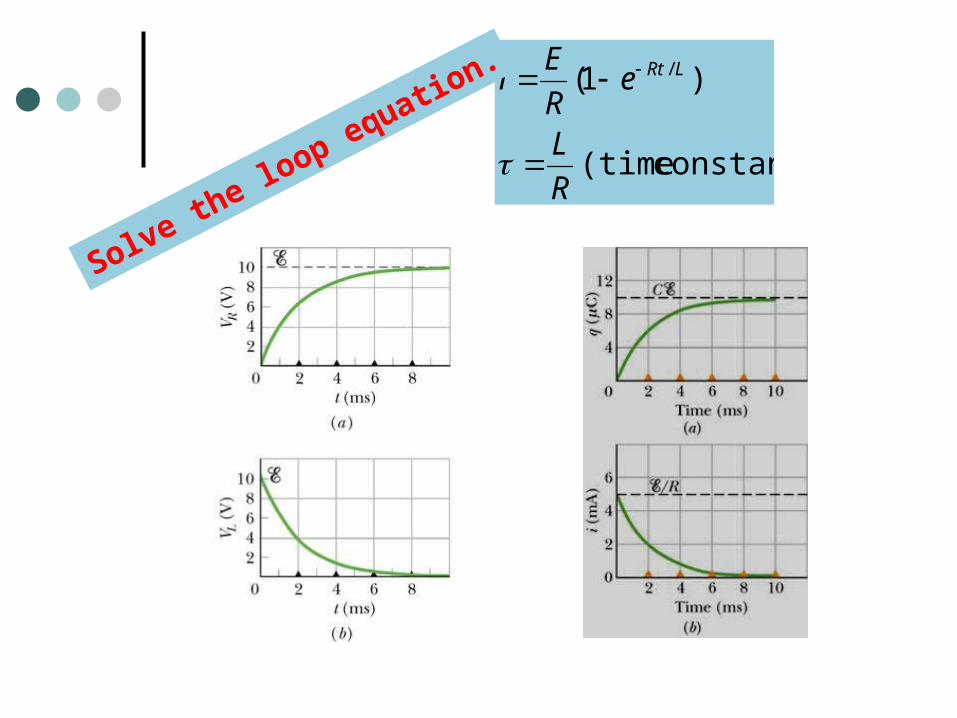
constant) (time
)1( /
R
L
eR
Ei LRt
Solve the lo
op equation.
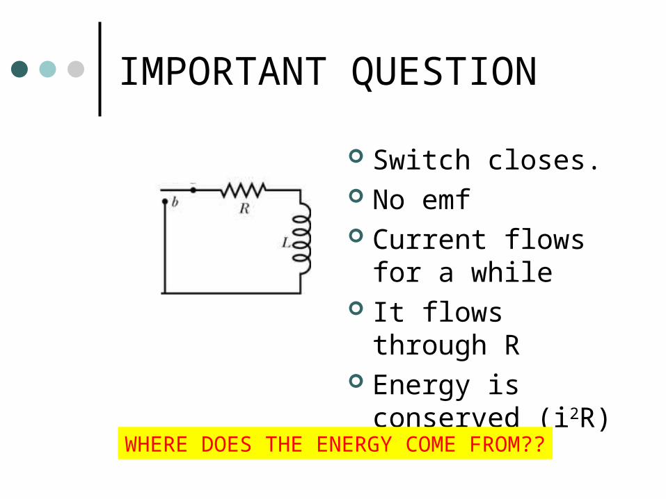
IMPORTANT QUESTION
Switch closes. No emf Current flows for
a while It flows through
R Energy is
conserved (i2R)WHERE DOES THE ENERGY COME FROM??
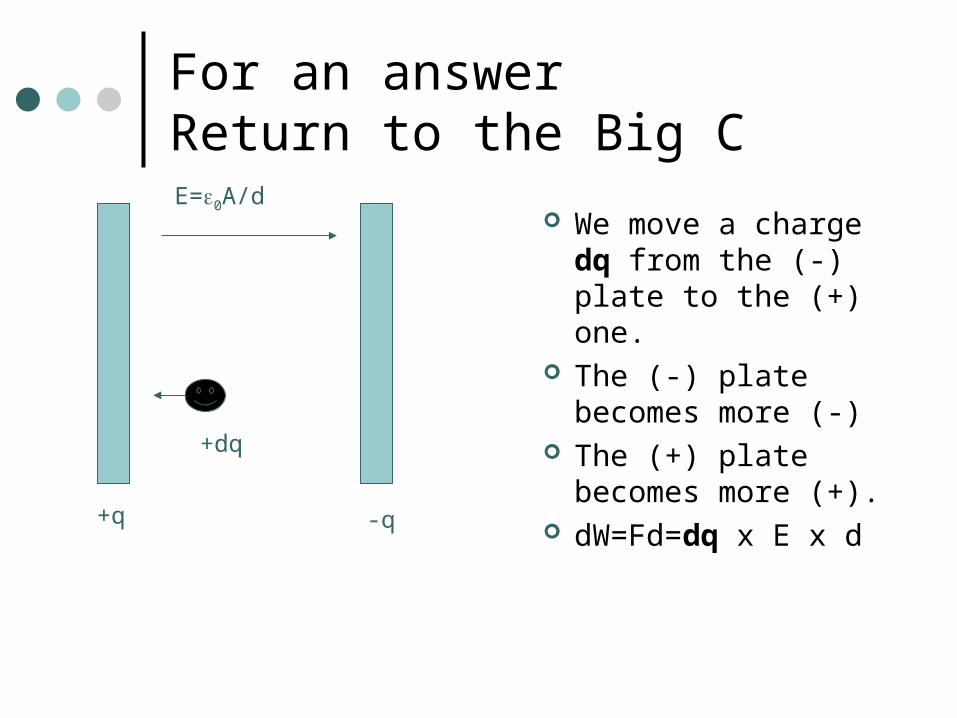
For an answerReturn to the Big C
We move a charge dq from the (-) plate to the (+) one.
The (-) plate becomes more (-)
The (+) plate becomes more (+).
dW=Fd=dq x E x d+q -q
E=0A/d
+dq
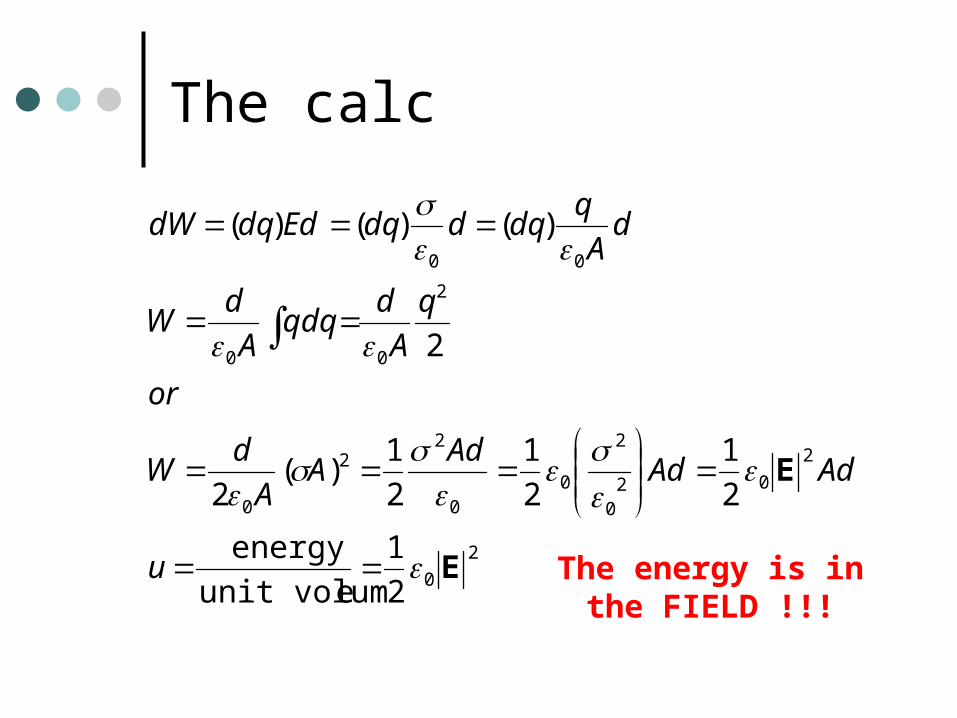
The calc
2
0
2
020
2
00
22
0
2
00
00
2
1
eunit volum
energy
2
1
2
1
2
1)(
2
2
)()()(
E
E
u
AdAdAd
AA
dW
or
q
A
dqdq
A
dW
dA
qdqddqEddqdW
The energy is inthe FIELD !!!
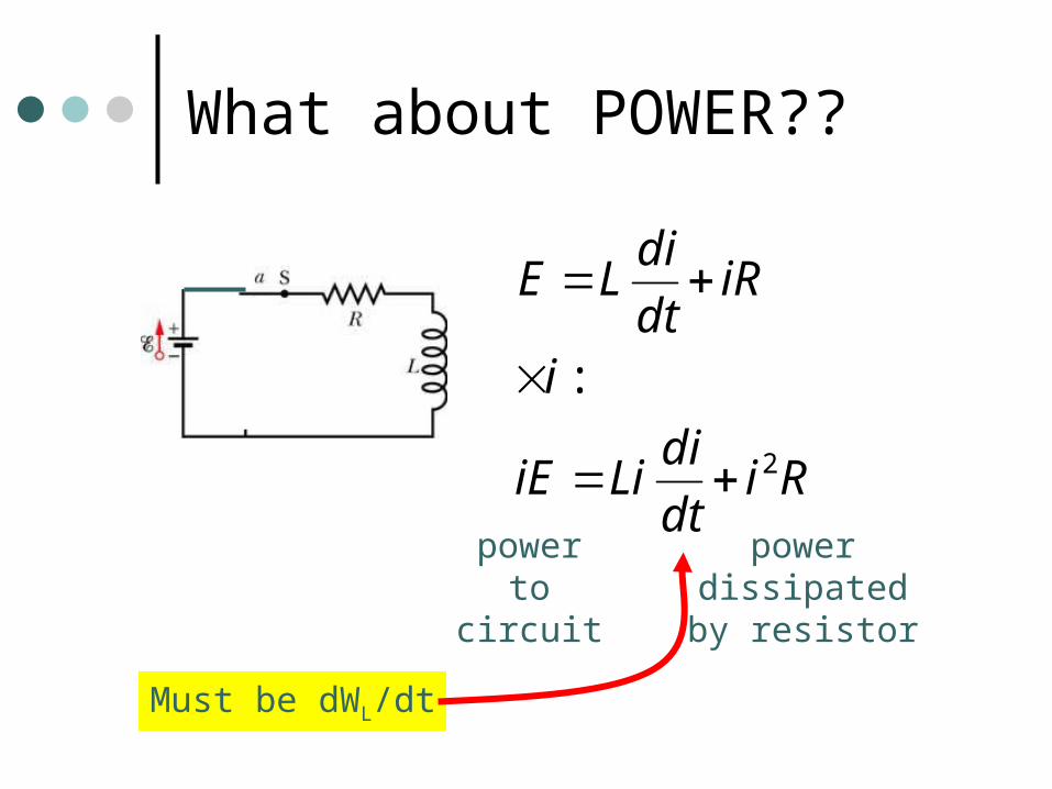
What about POWER??
Ridt
diLiiE
i
iRdt
diLE
2
:
powerto
circuit
powerdissipatedby resistor
Must be dWL/dt
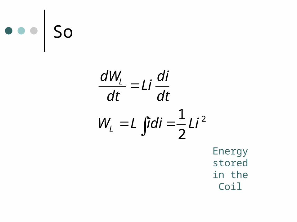
So
2
2
2
12
1
CVW
LiidiLW
dt
diLi
dt
dW
C
L
L
Energystoredin theCoil
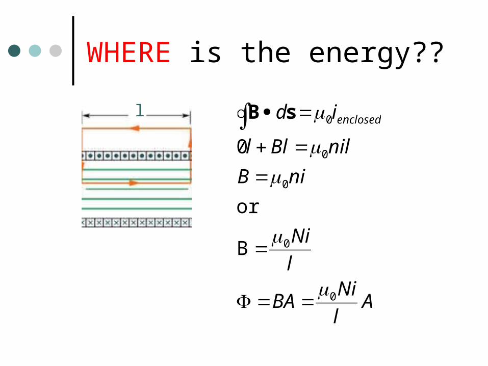
WHERE is the energy??
l
Al
NiBA
l
Ni
niB
nilBll
id enclosed
0
0
0
0
0
B
or
0
sB
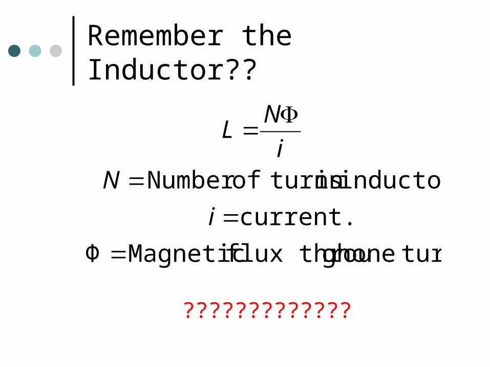
Remember the Inductor??
turn.onegh flux throu MagneticΦ
current.
inductorin turnsofNumber
i
Ni
NL
?????????????
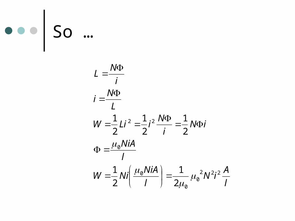
So …
l
AiN
l
NiANiW
l
NiA
iNi
NiLiW
L
Ni
i
NL
2220
0
0
0
22
2
1
2
1
2
1
2
1
2
1
2
0
2
0
22
0
0
2220
0
2
1
or
(volume) 2
1
2
1
B
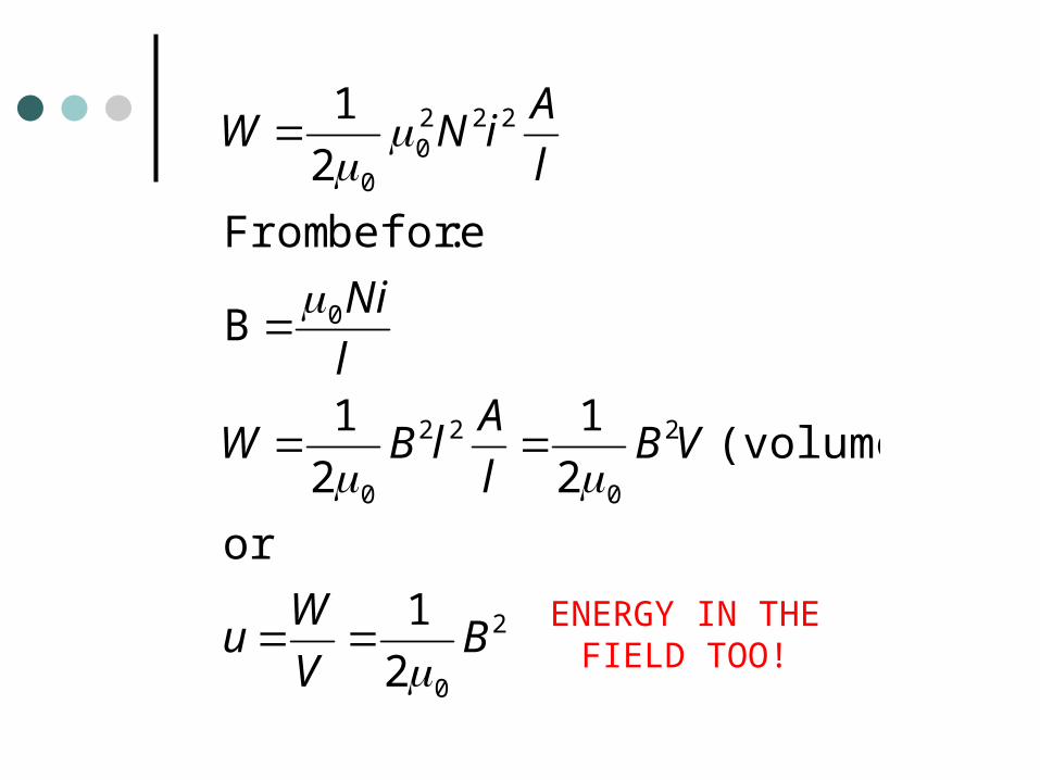
:before From
2
1
BV
Wu
VBl
AlBW
l
Ni
l
AiNW
ENERGY IN THEFIELD TOO!
IMPORTANT CONCLUSION
A region of space that contains either a magnetic or an electric field contains electromagnetic energy.
The energy density of either is proportional to the square of the field strength.
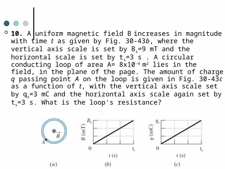
10. A uniform magnetic field B increases in magnitude with time t as given by Fig. 30-43b, where the vertical axis scale is set by Bs=9 mT and the horizontal scale is set by ts=3 s . A circular conducting loop of area A= 8x10⁻⁴ m2 lies in the field, in the plane of the page. The amount of charge q passing point A on the loop is given in Fig. 30-43c as a function of t, with the vertical axis scale set by qs=3 mC and the horizontal axis scale again set by ts=3 s. What is the loop's resistance?
29. If 50.0 cm of copper wire (diameter=1mm ) is formed into a circular loop and placed perpendicular to a uniform magnetic field that is increasing at the constant rate of 10.0 mT/s, at what rate is thermal energy generated in the loop?