Embed Size (px)
Citation preview

By Authority OfTHE UNITED STATES OF AMERICA
Legally Binding Document
By the Authority Vested By Part 5 of the United States Code § 552(a) and Part 1 of the Code of Regulations § 51 the attached document has been duly INCORPORATED BY REFERENCE and shall be considered legally binding upon all citizens and residents of the United States of America. HEED THIS NOTICE: Criminal penalties may apply for noncompliance.
Official Incorporator:THE EXECUTIVE DIRECTOROFFICE OF THE FEDERAL REGISTERWASHINGTON, D.C.
Document Name:
CFR Section(s):
Standards Body:
e


N-.--1990 EDITION

White Lakes Professional Bldg. 3310 SW Harrison Street
Topeka, Kansas 66611-2279
1990 Edition © 1990 Flat Glass Marketing Association, All Rights Reserved

ACKNOWLEDGMENT
We are most grateful to the many manufacturers, fabricators and FGMA members who have given freely of their respective time and resources to make possible the 1990 Edition of the FGMA Glazing Manual. We especially wish to thank the following for their assistance in the assembly of the material herein and their critical reviews of the several drafts that, of necessity, preceded the final copy:
R. H. "Harry" Miles, AFG Industries, Inc. Joseph Schultheis, EPI Architectural Systems Raymond Nalepka, Guardian Industries Corp Mike Haugsby, Dow Corning Dick Joyce, Dlubak Studios Shannon Singleton, Libbey-Owens-Ford Glass Co. G. R. Davis, PPG Industries, Inc. John Vermeersh, Kawneer, Inc. Randy Wright, Monsanto Stanley Kam, Tremco Tom Schwartz, Simpson, Gumpertz & Hegar Jack Roehm, P. E., Consultant to AAMA Richard Wright, Consultant J. E. Minor, Ph.D., P. E. Bob Spindler, CardinalI. G.
Appropriate acknowledgement has been made to various publications, associations and companies by footnote where charts from their publications have been used or portions of their texts have been directly quoted.
Our thanks go to all these and the many others who contributed information, assistance and advice.
INTRODUCTION
A Risher Hall, P. E. Technical Consultant
Glass in windows, curtainwalls and skylights will produce important energy-saving benefits when properly designed and managed.
The use of daylighting in commercial buildings will reduce the demand for artificial lighting. Artificial lighting is the largest single user of energy in typical office buildings; daylighting is free. Energy costs to overcome heat gain and loss through glass are much less than for artificial lighting. Arbitrarily limiting glass area to a small percentage of exterior wall or roof area can produce higher operating costs than larger welldesigned and well-managed areas.
Glass on sun-facing orientations of residences, properly managed, will act as passive solar collectors to offset a portion of winter heating costs. When double or triple glazing is used, especially in conjunction with a LowEmissivity coating, the net effect will be energy consumption comparable to that of many opaque walls. When used with awnings, overhangs or indoor shading devices to reject summer sun, windows can be energy-efficient and cost-effective in most seasons and climates.

INTRODUCTION TO FGMA
FGMA represents the larger independent glass distributors and installers throughout the United States. Since many of the members are multiple branch operators, FGMA is represented in approximately 225 cities across the country. The typical FGMA member is involved in distribution (20-30%) and contract glazing (70-80%). A number of member firms distribute only (including auto glass), and others are strictly glazing contractors.
The FGMA staff has many years of experience in the industry and serves as a clearinghouse for member inquiries and requests for assistance. The staff is in continual contact with all segments of the industry, and organizations and associations outside the industry involved in activities that may ultimately affect member interests.
FGMA retains a General Counsel in Washington, D.C. His office monitors the activities of the Congress and various regulator agencies. In addition, he attends regular meetings of the Association to ensure strict compliance with all applicable laws and regulations, particularly those involving anti-trust. He also serves as an advisor to the FGMA officers, directors and staff and periodically reviews all Association activities. He is available for member consultations regarding matters in which the Association may be involved.
As a part of our extensive labor program, FGMA retains a Labor Counsel in Kansas City to advise the Association and to assist members with labor-related problems. He is available to individual members for office or phone consultations at no charge. If a member requests services that go beyond consultation, the time involved will be billed directly to the member firm. Labor updates are provided on an as-needed basis.
Active committees in the areas of auto glass, consumer safety, energy, labor, programming, education and finance are the backbone of the Association activities. Each committee is provided a budget for necessary travel and meeting expenses and has specific responSibility for advising the Association on matters assigned to it. In addition to its own committee activities, FGMA is an active participant in the Glazing Industry Code Committee and the Auto Glass Industry Council. These organizations are involved in areas of immediate concern to FGMA members and the glass and glazing industry.
FGMA is continually updating its technical publications. Our Glazing Manual is the industry bible on good glazing practices and is referenced in virtually all specifications. The Association also publishes the Fabrication, Erection and Glazing Hours Manual, the Sealant Manual and our Labor Manual. Additionally, the Association has a Blue Print Reading Course for beginning estimators and an Advanced Estimating Course for estimators with more than five years experience. There are approximately 1,100 students enrolled in these courses at all times.
Meetings are a major part of the services offered by FGMA They provide frequent opportunities for members to meet with peers, suppliers and others involved in the industry. The Association sponsors one-day regional meetings in the spring that are for members only. These are nuts-and-bolts type sessions and provide members an opportunity to discuss specific matters of interest. The fall meetings are regional and three days in duration.
Our annual meeting is held in conjunction with the Glass Tempering, Laminators Safety Glass and Sealed Insulating Glass Manufacturers Associations, and is called Glass Week. Glass Week is recognized as a major industry event; it features a broad range of outstanding speakers from industry and business and an extensive social program. One day of Glass Week is devoted to individual association meetings.
FGMA is committed to a continuing effort to develop the management sophistication that will be required in the 1990s, while maintaining a posture that will permit immediate response to matters of importance to members and the industry.
FLAT GLASS MARKETING ASSOCIATION 3310 Harrison Topeka, Kansas 66611-2279 Tel. (913) 266-7013 Fax (913) 266-0272
ii

ORGANIZATIONS PUBLISHING REFERENCED STANDARDS AND INFORMATION
Standards of the following organizations are referred to, usually by the organizations' abbreviated names, wherever pertinent in these specifications. For up-to-date design and technical information, as well as for more complete data if needed, these organizations would be consulted.
Organization
The Aluminum Association 818 Conn Ave. N., Washington, D.C. 20006
American Architectural Manufacturers Assn. 2700 River Road, Suite 118 Des Plaines, Illinois 60018
American Institute of Architects 1735 New York Ave., Washington, D.C. 20006
American Institute of Steel Construction 410 N. Michigan, Chicago, Illinois 60610
American Iron and Steel Institute 1000 6th Street, Washington, D.C. 20036
American National Standards Institute 1430 Broadway, New York, New York 10018
American Society of Civil Engineers 345 East 47th Street, New York, New York 10017
American Society of Heating, Refrigerating, and Air-Conditioning Engineers 1791 Tullie Circle, NE, Atlanta, Georgia 30329
American Society for Testing and Materials 1916 Race Street, Philadelphia, Pennsylvania 19103
American Welding Society 2501 Northwest 7th Street, Miami, Florida 33125
Associated Laboratories, Inc. P.O. Box 15705, Dallas, Texas 75215
Canadian Government Specifications Board 99 Metcalfe Street, Ottawa, Ontario KIA OS5
Construction SpeCifications Institute 1150 17th Street NW, Washington, D.C. 20036
Federal SpeCifications General Services Administration (WFSIS) Bldg. 197, Navy Yard Annex, Washington, D.C. 20407
Flat Glass Marketing Association 3310 Harrison, Topeka, Kansas 66611
Glass Tempering Association 3310 Harrison, Topeka, Kansas 66611
iii
Abbreviated Name
AA
AAMA
AlA
AlSC
AlSI
ANSI
ASCE
ASHRAE
ASTM
AWS
ALI
CGSB
CSI
FS
FGMA
GTA
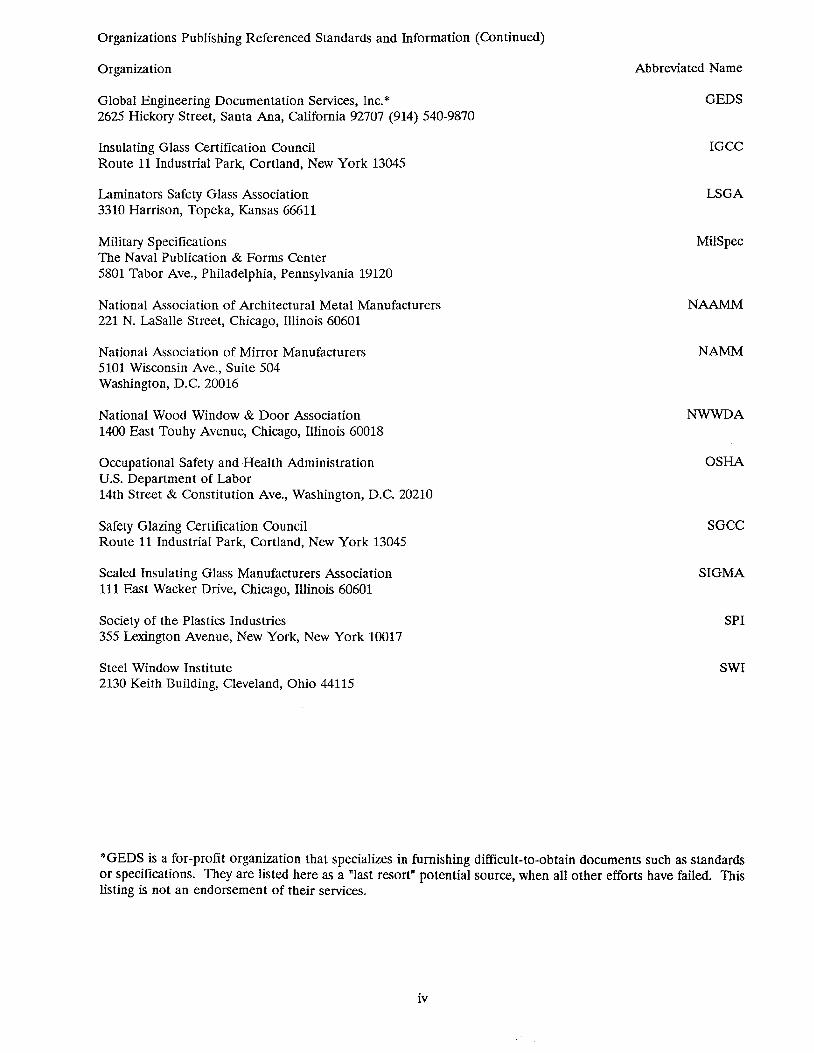
Organizations Publishing Referenced Standards and Information (Continued)
Organization
Global Engineering Documentation Services, Inc. * 2625 Hickory Street, Santa Ana, California 92707 (914) 540-9870
Insulating Glass Certification Council Route 11 Industrial Park, Cortland, New York 13045
Laminators Safety Glass Association 3310 Harrison, Topeka, Kansas 66611
Military Specifications The Naval Publication & Forms Center 5801 Tabor Ave., Philadelphia, Pennsylvania 19120
National Association of Architectural Metal Manufacturers 221 N. LaSalle Street, Chicago, Illinois 60601
National Association of Mirror Manufacturers 5101 Wisconsin Ave., Suite 504 Washington, D.C. 20016
National Wood Window & Door Association 1400 East Touhy Avenue, Chicago, Illinois 60018
Occupational Safety and Health Administration U.S. Department of Labor 14th Street & Constitution Ave., Washington, D.C. 20210
Safety Glazing Certification Council Route 11 Industrial Park, Cortland, New York 13045
Sealed Insulating Glass Manufacturers Association 111 East Wacker Drive, Chicago, Illinois 60601
Society of the Plastics Industries 355 Lexington Avenue, New York, New York 10017
Steel Window Institute 2130 Keith Building, Cleveland, Ohio 44115
Abbreviated Name
GEDS
IGCC
LSGA
MilSpec
NAAMM
NAMM
NWWDA
OSHA
SGCC
SIGMA
SPI
SWI
*GEDS is a for-profit organization that specializes in furnishing difficult-to-obtain documents such as standards or specifications. They are listed here as a "last resort" potential source, when all other efforts have failed. This listing is not an endorsement of their services.
iv

INDEX
I. PRIMARY GLASS PRODUCTS ................................................... 1 Float Glass .................................................................. 1 Sheet Glass . . . . . . . . . . . . . . . . . . . . . . . . . . . . . . . . . . . . . . . . . . . . . . . . . . . . . . . . . . . . . . . . .. 1 Plate Glass .................................................................. 1 Rolled Glass ................................................................. 1
II. FABRICATED GLASS PRODUCTS ................................................ 3 Insulating Glass . . . . . . . . . . . . . . . . . . . . . . . . . . . . . . . . . . . . . . . . . . . . . . . . . . . . . . . . . . . . . .. 3 Reflective Glass. . . . . . . . . . . . . . . . . . . . . . . . . . . . . . . . . . . . . . . . . . . . . . . . . . . . . . . . . . . . . .. 4 Heat-Treated Glass ............................................................ 6 Chemically Strengthened Glass ................................................... 8 Spandrel Glass ............................................................... 8 Laminated Glass .............................................................. 10 Bent Glass .................................................................. 11 Mirrors ..................................................................... 11
III. QUALITY STANDARDS ......................................................... 13 Primary Glass ................................................................ 14 Tempered, Heat-Strengthened & Spandrel Glass ...................................... 16 Suggested File of Reference Materials .............................................. 18
IV. SURFACE FINISHES & LABELING ................................................ 19 Surface Finishes on Glass ....................................................... 19 Labeling of Float Glass ......................................................... 19
V. DESIGN CONSIDERATIONS ..................................................... 20 General .............................. '" .... , ............................... 20 Structural Performance of Glass .................................................. 20 In-Service Exposures of Glass .................................................... 21 Design Load ................................................................. 21 Sloped Glazing ............................................................... 25 Glass Thickness Selection ....................................................... 26 Energy Terminology & Heat Transfer .............................................. 28
VI. SOUND TRANSMISSION ........................................................ 31 VII. SAFETY GLAZING IN HAZARDOUS LOCATIONS ................................... 39
VIII. GENERAL GUIDELINES FOR GLAZING ........................................... 40 IX. SPECIFIC GUIDELINES FOR GLAZING ............................................ 52
Compatibility ................................................................ 52 Glass Setting ................................................................. 52 Wet Glazing ................................................................. 52 Lateral Shims ................................................................ 53 Dry Glazing .................................................................. 53 Wet!Dry Glazing .............................................................. 55 Cap Beads ................................................................... 56 Pressure Glazed Systems ........................................................ 56 Structural Gaskets ............................................................. 56 Butt-Joint Glazing ............................................................. 57 Structural Silicone Glazing ...................................................... 58 Sloped Glazing ............................................................... 63 Bent Glass .................................................................. 63 Laminated Glass .............................................................. 65 Heat-Treated Glass ............................................................ 66 Insulating Glass ............................................................... 66 Wrap-Around (Marine) Glazing .................................................. 66 Special Systems ............................................................... 66 Acrylic & Polycarbonate Sheet .................................................... 67 Mirrors ..................................................................... 68
X. GLOSSARy ................................................................. 70
v

, L ~1a11\1l~1a~'~~~$$ l!~mmlU~m~' i"~ <', ','; ; , ',"/, ':1' , , '
, ~"Ci J;"
FLOAT GLASS The Float Glass Process accounts for over 98% of the flat glass presently produced in the United States.
During this process, molten glass is poured continuously from a furnace onto a large bed of molten tin. The molten glass literally floats on the tin, spreading and seeking a controlled level in the same manner as water poured onto a smooth, flat surface.
In the controlled, level-seeking process, the molten glass typically is allowed to spread to a width of 90" to 140", depending on the furnace size and glass thickness being produced. The glass slowly solidifies as it travels over the molten tin. It then enters an annealing lehr where the cooling process continues under controlled conditions. After several hundred feet of travel through the lehr, it emerges as a continuous ribbon of glass at essentially room temperature. The product is now flat and fire-finished, and has virtually parallel surfaces.
Automatic cutters generally are used to trim the edges and to cut across the width of the moving ribbon. This creates sizes which can be shipped or handled for further processing.
CLEAR GLASS Clear Glass consists of silica sand with added alkaline salts such as lime, potash and soda. It is colorless and
has a visible light transmittance ranging from 75% to 92%, depending on thickness. Clear Glass constitutes the bulk of the flat glass used.
TINTED/HEAT·ABSORBING GLASS Tinted or Heat-Absorbing Glass is made by adding various colorants to the normal, clear glass batch to create
a desired color. The four colors produced domestically are bronze, gray, green and blue. Europe produces some other colors, for instance rose and emerald green. Visible light transmittance will vary from 14% to 83%, depending on the color and thickness. The color density is a function of thickness and increases as the thickness increases; visible light transmittance will decrease as thickness increases.
Tinting, which reduces the solar transmittance of glass and has little effect on solar reflectance, increases solar absorption (heat). This explains why heat strengthening or tempering is sometimes required for the thicker, tinted glasses. Adding a metallic coating can also have the same effect.
ASTM Specification C 1036 separates Heat-Absorbing and Tinted (light-reducing) Glasses into categories based on the maximum solar energy transmittance, by glass thickness. Nevertheless, all tinted glass is heat-absorbent to some degree. The bronze, gray, green and blue tints produced by the float process are all classed as heatabsorbent.
SHEET GLASS The Sheet Glass Process accounts for a very small portion of U.S. production. Some imported Sheet Glass
continues to be used, mainly in thicknesses of 1/8" and less.
PLATE GLASS Plate Glass, manufactured by the grinding and polishing process, is no longer produced in the United States,
and words referring to it have been eliminated from the ASTM Specification C 1036. It has been replaced by the float glass process.
ROLLED GLASS The Rolled Glass Process consists of pouring molten glass from a furnace, then feeding it through rollers to
produce the desired thickness and pattern. The glass ribbon then enters a lehr where the cooling continues under controlled conditions.
There are three general types of Rolled Glass: figured/patterned, wired and art/opalescent/cathedral glass.
FIGURED/PATTERNED GLASS Figured/Patterned Glass is produced domestically by the continuous pour process in thicknesses of 1/8" to 7/32".
A pattern etched on one or both of the rollers is reproduced on the glass. Colors are available but extremely limited.
This type of glass is frequently called "obscure" or "decorative" glass. The pattern diffuses detail of Objects viewed through the glass, but it does not obscure them. The degree of diffusion achieved is a function of the pattern and whether the pattern is on one or both sides.
Some patterns cannot be heat-strengthened or tempered because of their depth.
1
WIRED GLASS Wired Glass is produced on the same equipment as is figured/patterned glass. A welded wire netting is
introduced into the molten glass just before entering the rolls, thus embedding the wire into the glass. Patterned Wired Glass has a pattern on one or both sides and is sometimes called "rough" Wired Glass. Polished Wired Glass is produced by grinding and pOlishing rolled Wired Glass blanks.
Tinted/heat-absorbing Wired Glass is available only as an import. The heat-absorbing characteristic in conjunction with the normally poorly cut edges and the wire netting can cause a high rate of breakage from thermal stress, especially in non-vertical applications.
The major uses of Wired Glass are in institutional buildings and fire-rated windows and doors. All wires must be completely embedded in the glass. Some misalignment of the wires may be noticeable, but this is not considered cause for rejection.
Wired Glass cannot be tempered. It is considered to be approximately 50% as strong as annealed glass of the same thickness, when subjected to wind load.
The edges of Wired Glass should be sealed from water to prevent rusting of the embedded wires. This can be accomplished either by physically sealing the perimeter of the lite with a sealant or by glazing in such a manner that the glazing rabbet will always remain dry. The iron oxide molecule is larger than the iron molecule, so rusting of the wires will cause glass breakage.
Most building codes require that Wired Glass meet NFP A 80 or be classified by u.L. as a fire-resistant glazing when used in fire doors or windows.
Wired Glass does not meet the requirements of CPSC 16 CFR 1201 and cannot be used as a safety glazing material in situations governed by that law.
ART/OPALESCENT/CATHEDRAL GLASS Colored translucent glass, often called Art Glass, Opalescent Glass, Cathedral Glass or Stained Glass, is also
produced by the rolling process but generally in small, batch-type operations. There are usually variegated colors within each sheet produced, and no two sheets will match for hue. Thickness will vary within a sheet as well as from sheet to sheet. The maximum thickness produced is usually 1/8".
When used as a glazing material, Art Glass should be glazed in the same manner as tinted/heat-absorbing glass. Art Glass cannot be heat-strengthened or tempered.
Because leaded windows and other applications of Art Glass are a separate subject, details will not be covered in this manual.
2

~ ~ ~ i' '"' .,.
II. e;~BIaI~~tEEm ~1ll1~SS ela€)~l:J~mS _ " 0 _
INSULATING GLASS UNITS Most insulating glass units consist of two panes of glass enclosing a hermetically sealed air space. The panes
are held apart by a spacer around the entire perimeter. The spacer contains a moisture-adsorbent material, called a desiccant, that serves to keep the enclosed air free of visible moisture. The entire perimeter of the assembly is sealed with an organic sealant.
The most commonly used edge (spacer) construction is a metallic spacer of roll-formed aluminum or galvanized steel. It is sealed with a single seal of polysulfide, polyurethane or hot-melt butyl, or with a dual seal consisting of a primary seal of polyisobutylene and a secondary seal of silicone, polysulfide or polyurethane. The comers of the metallic spacer may be square-cut and joined with a cast metal or cast nylon comer key, may be miter-cut and brazed, welded or soldered, or may be bent.
Some units, mainly for residential use, are manufactured by a patented welded glass-edge process and contain no desiccant, but are purged of air and filled with dry nitrogen or other suitable dried gas. These are available only in relatively small sizes, thin glasses and very large quantities per size.
Some units, specifically for extremely cold regions, are built with two, or even three, air spaces and therefore have three or four lites of glass.
There are also some proprietary unit constructions which have specific attributes that make them distinctive: SWIGGLEe is a butyl spacer impregnated with desiccant and backed with a corrugated aluminum strip. It is very amenable to short-run production of limited sizes, with or without a secondary sealant. There are size and application limitations. SUPER SP ACERe is a silicone spacer impregnated with desiccant and backed with an aluminum foil. A secondary seal of hot-melt butyl is preferred, although polysulfide or polyurethane probably may be satisfactory. There are size and application limitations. HEAT MIRROR- consists of two lites of glass and two spacers. A coated polyester film is centered between the spacers and retained by them, which creates two air spaces. The units feature U-values considerably lower than those of regular construction. I/S~ is a unit with a 2" air space and an extruded aluminum spacer. The vertical spacer is very heavy and also acts as a vertical mullion, permitting the units to be butt-glazed in horizontal ribbons without mullions. With various glass combinations, STC ratings as high as 48 can be achieved.
The insulating properties of insulating glass also can be substantially improved by adding solar-reflective coatings and Low-Emissivity (Low-E) coatings, as well as by filling the air space with a heavy gas such as argon. Filling with a gas such as sulfur hexafluoride (SF6) will aid in lowering sound transmission. Sometimes the two gases are used in combination. The effects of solar reflective and Low-E coatings and gas filling are set forth later in this chapter and in Chapter V.
CERTIFICATION The purpose of a certification program is to assure the user that the purchased product is a faithful replica of
one that has passed certain prescribed tests. Therefore, participants in a certification program must complete the following requirements: (a) submit specimens of their product to independent testing laboratories for the prescribed tests; and (b) agree to periodic, unannounced inspections of their regular production by an independent agency to ensure that actual production employs the same materials and techniques as the tested specimen. For insulating glass, there are four (4) programs approved by the Sealed Insulating Glass Manufacturers Association; their names can be obtained from that organization. One, the Insulating Glass Certification Council, is an independent, non-profit organization whose management is vested in a Board of Governors with a balance of industry and public interest members elected by the participants. All IGCC meetings are open to the public.
DISTORTION The air (or gas) sealed within an insulating glass unit will respond to the gas laws of physics from the moment
the unit is sealed. These laws govern the volume of gas as it relates to changes in temperature and pressure. As the sealed-in air is heated or cooled, it expands or contracts in volume. As the barometric pressure falls or rises, it likewise expands or contracts. This causes the two panes to bow away from or toward each other. They virtually will be in constant motion in response to hourly temperature and barometric changes, and therefore seldom ever parallel or flat. When the glass is in a reflective mode, the Objects reflected will appear distorted. There is no known method by which the identical internal volume, air temperature and pressure can be achieved in each and every insulating unit for a specific project and still have the advantages of a sealed unit. Even if there were,
3
distortion would still be evident in units with heat-treated glass and from unequal glazing pressures around the perimeter.
Some manufacturers have produced units with a permanent breather tube of capillary dimensions to eliminate distortion caused by the above laws. These, of course, cannot be considered to be hermetically sealed. They generally have not fared as well as hermetically sealed units when subjected to the ASTM E 773-774 testing procedure.
WARRANTIES Since no two insulating glass manufacturers use the same combination of components and fabrication
techniques, no two warranties are exactly alike. Warranties usually require adherence to certain installation procedures or techniques, and exclude glass breakage and the replacement glazing labor.
RETROFIT Systems have been developed to convert single glass into insulating glass in existing buildings. These systems
invoL.:: cleaning the interior of the existing glass and applying a desiccated spacer, a second (new) pane of glass and a perimeter sealant. This is generally most effective on fIxed (non-operable) windows. Optimum performance is generally achieved by using a reflective glass as the new pane. Since every project is custom, workmanship and warranties will vary. Since this is a fIeld assembly, the workmanship is critical. Even in the controlled environment of a factory, cleanliness and good workmanship is essential, and work in the fIeld is more demanding.
REFLECTIVE GLASS There are two basic types of reflective glass: Solar-Reflective and Low-Emissivity (Low-E). The major
differences are visible light transmission, wavelengths of energy that are reflected and the direction in which these wavelengths are usually reflected. Both types have metallic or metallic-oxide coatings that are applied to the glass with the same basic type of equipment.
Solar-Reflective Glass has a mirror-like metallic or metallic-oxide coating that is highly reflective of solar energy, Le., those energy wavelengths from 300-2100 millimicrons that constitute the solar spectrum. Shading coefficient is the measure of the coating's efficiency. The shading coefficient of 1/8" clear glass is 1.00; shading coefficients of solar-reflective glass can be as low as 0.14, Le., such a coated glass will transmit only 14% as much of the solar spectrum as would 1/8" clear glass in the same location.
The solar spectrum consists of the ultraviolet (UV), the visible and the infrared (IR). Their wavelength ranges are 300-380 millimicrons for the UV, 380-700 millimicrons for the visible and 700-2100 millimicrons for the IR. The distribution of heat within the solar spectrum is approximately 2% UV, 46% visible and 52% IR.
Shading coefficient is related to solar transmission, not visible light transmission. A 24-carat gold coating will have, in an insulating unit, a shading coefficient of 0.14 while having a visible light transmission of 20%; however, a stainless steel coating in a similar unit might need a heavier coating, resulting in only 8% visible light transmission to achieve the same 0.14 shading coefficient.
In addition to low shading coeffient, the major attributes of solar-reflective glass include the following: a) Esthetic Appeal. The various silver, gold, copper and blue reflective coatings, when combined with clear,
bronze, gray, green and blue float glass, allow the architect more flexibility with exterior design than with clear glass.
b) Energy Savings. Through its ability to reflect, absorb and reradiate solar energy, solar-reflective glass will substantially reduce interior solar heat gain. The added cost of the coating will generally be offset by the reduced size (cost) of the HVAC systems. Operating costs will likewise be reduced.
c) Occupant Comfort. Occupant comfort is improved when heat gain/loss differentials between sunny and shaded elevations are substantially reduced. Interior temperature differentials are less and thus easier to control.
Low-Emissivity (Low-E) Glass has a metal or metallic-oxide coating that is nearly invisible to the eye and reflects that IR portion of the heat spectrum whose wavelength is longer than 3000 millimicrons. The "long" IR can be described as the radiant heat given off by an electric coil-type heater as well as the sensible heat that comes from a hot air register. The reradiated heat from room furnishings that have absorbed solar energy is still another form of sensible heat.
The Low-E coatings reflect the long IR, generally back into the occupied space of a home or office, thus reducing the heat loss through the glass in winter. Used in conjunction with a tinted (heat-absorbing) glass in an insulating unit, a Low-E coating will reject to the exterior the reradiated heat from the tinted glass; this would be an acceptable use to reduce interior heat gain in warm climates.
U-Values as low as 0.30 can be achieved with Low-E coatings on the second or third surface of insulating glass units. Low-E coatings can be combined in an insulating unit with a solar-reflective coating and gas filling to create
4

a "super" insulating unit having a shading coefficient as low as 0.10 and a U-Value as low as 0.25. Table 10 demonstrates many of the above characteristics.
METHOD OF MANUFACTURE There are two methods of coating deposition used in the manufacture of reflective glass: Magnetic Sputtering
and Pyrolitic Deposition. Magnetic Sputtering involves a large vacuum chamber, an inert or reactive gas atmosphere, and electrical
energy. The electrical energy imparts a negative charge to the atoms or molecules of the gas. The vacuum pressure, which is .0006 to .000006 psi (compared to 14.75 psi normal atmospheric pressure) allows the negatively charged particles to move freely at high velocity. When those charged particles strike a cathode, atoms of the metal or metallic oxide are dislodged from the cathode, also with high velocity. These impinge upon the glass substrate, creating a thin layer of the metal or metallic oxide. Coating hardness and adhesion is a function of the cathode material and its impact velocity.
Many solar-reflective coatings can be used monolithically or shipped to another location for fabrication into insulating units. Heat treating, if required, must be done prior to the coating process.
Magnetically sputtered Low-E reflective coatings cannot be used monolithically; they must always be fabricated into an insulating unit. The coating should be on the second surface for use in semi-tropical locations and on the third surface for cold climate usage.
Pyrolitic Deposition applies a metallic-oxide coating to hot glass. The process can be accomplished in a properly equipped heat-strengthening furnace or on a float glass line near the cool end of the tin bath or the hot end of the lehr. The metallic oxide is literally impregnated into the still-soft surface of the glass. Pyrolitically coated annealed glass can be heat-treated without affecting the coating.
Pyrolitically coated solar-reflective glass is usually installed with the coated surface to the exterior for best shading coefficient. It can also be installed with the coated surface facing inward; frequently, heat treating is required for this configuration. A ceramic frit coating can be fired onto the inward surface in either case without affecting the reflective coating.
Pyrolitically coated Low-E glass must always be installed with the coated surface facing inward, if monolithic. The sputtered Low-E product is generally more efficient than the pyrolitic product, i.e., it will have a lower UValue.
Some sealants used for glazing may cause staining of pyrolitic coatings. Since formulation of a specific sealant or tape may Change without notice, it is wise to check with the sealant or tape manufacturer for every installation where the tape or sealant will contact the coating.
SPECIFICATION All reflective glasses of the same general color and visible light transmission are not alike in visible reflectance
and other solar-optical properties, shading coefficient, or V-Value. The typical performance specification should state the primary type of glass, desired color of coating, visible light transmission, shading coefficient, and winter and summer V-Values. Any alternate bids for glass having different values should have a companion alternate in the mechanical specifications if those values are sufficiently different as to affect the size (larger or smaller) of the mechanical system.
The specifications should include a provision for construction of a full-size mock-up incorporating the reflective glass and framing, for viewing and approval by the architect and owner. The mOCk-up should be located at the job site, thus giving a preview of the reflective qualities, distortions, etc., under real-life conditions.
Since different types of coatings and different metallic oxides are used for Low-E coatings, the above is true for them as well as for solar reflective coatings. Low-E coatings of different characteristics will have subtle differences of hue or color that may not be apparent in small hand samples.
COATING DEFECTS There is no national or industry standard that describes allowable limits of defects in reflective coatings.
Defects may range from pinholes, streaking or mottling to scuffs and scratches. Pinholes, streaking and mottling are generally manufacturing defects. Scuffs and scratches may be handling, process, transportation, glazing or postglazing anomalies. The manufacturer should be required to submit its in-house criteria for manufacturing defects.
In the case of insulating units with second- or third-surface coatings, scuffs and scratches are obviously process defects and should be defined in the manufacturer's criteria. In the case of monolithic coatings, scuffs and scratches may occur at any point after manufacture. Glass should be inspected when unpacked at the job site, again immediately after glazing and finally at punch list time to determine responsibility for the defects.
Monolithically coated glass and glass with the coating on the first surface can also be damaged as a result of harsh cleaners by window washers, interior decorators and building occupants unless good warning is given to them.
5
RETROFIT REFLECTIVE FILMS Organic coatings or reflective films can be applied to existing in-place glass to reduce excessive solar heat gain
or glare. These are generally a flow-on acrylic plastic, or a tinted or metallized pOlyester, adhesive-coated film. These coatings not only reflect but also absorb solar energy. This will generally cause higher edge stresses in the glass than existed before application of the film, possibly causing glass breakage which otherwise would not occur.
Before proceeding with a large scale installation, a few windows should be done in a location where solar exposure would be maximum and left for at least two full annual cycles.
As a general rule, the follOwing limitations are advisable: a. Do not apply films to annealed, heat-absorbing (tinted) glasses. b. Do not apply films to the room-side surface of insulating units. Some manufacturers will void their
insulating glass warranty if films are so applied. Glass breakage may result, especially if the outboard lite is heat absorbing (tinted) glass.
HEAT-TREATED GLASS Heat-Treated Glass is fabricated by subjecting annealed glass to a special heat-treating process. The most
commonly used process heats the glass uniformly to approximately 1150°F, then rapidly cools it by blowing air uniformly onto both surfaces simultaneously. The cooling process locks the surfaces of the glass in a state of high compression and the central core in compensating tension. The compression and tension layers are separated by neutral layers; each of the five (5) layers constitutes approximately 20% of the thickness of the lite.
The color, clarity, chemical composition and light transmission characteristics remain unchanged. Likewise, compression strength, hardness, specific gravity, expansion coefficient, softening pOint, thermal conductivity, solar transmittance and stiffness remain unchanged. The only physical property that changes is bending strength. Under uniform loading, heat-treated glass is stronger than annealed glass of the same size and thickness, and thus more resistant to thermally induced stresses, cyclic wind loading and impacts by windborne objects and hail.
Heat-Treated Glass is separated into two products, heat-strengthened glass and fully tempered glass, by definition of the degree of residual surface compression or edge compression. Most furnaces can produce both. A furnace and its quench must be adjusted by its operator for one or the other of a product "run." The adjustments may include changes in furnace temperature, exit temperature of the glass, residual time in the furnace, and volume and pressure of the quench air.
PRODUCTION There are two basic methods for producing air-quenched heat-treated glass. In one method, the glass moves
through the furnace and quench in a vertical position; in the other it moves on rollers of stainless steel or highstrength ceramic in a horizontal position.
Each method produces some degree of bow and warp, which is an inherent characteristic of all heat-treated glass. Tong-held glass, the vertical process, may exhibit a long arc or "S" curve plus some minor distortion at the tong points. Horizontally heat-treated glass will have characteristic waves or corrugations caused by the support rollers. Tolerances permitted by ASTM C 1048 are in the Quality Standards section of this manual.
LIMITATIONS Recommended maximum service temperature for heat-treated glass is approximately 500° F. Heat-treated glass
is not classified as a fire-retardant material. Tempered glass, although stated as being four (4) times stronger than annealed glass, and heat-strengthened
glass, stated as being two (2) times stronger than annealed glass, should not be selected to meet a given wind load simply because annealed glass of the same size and thickness is insufficient. The stiffness of annealed glass and heat-treated glass is the same; deflection under a given uniform load (wind load) will be identical for glass of the same size and thickness. Excessive deflection can cause glazing sealant failure - glass breakage by contact with the framing - as well as occupant psychological discomfort.
Heat-treated glass cannot be cut, drilled or edged after being heat-treated. It should be sandblasted or acidetched with caution. Either of these processes may reduce the thickness of the compression layer somewhat, thus reducing the strength of the lite.
Some deep patterns of rolled glass cannot be heat-strengthened, or, if tempered, will not break in the manner prescribed by CPSC 16 CFR 1201 or ANSI Z97.1 for safety glazing products.
Iridescence, spots or splotches may be visible at times, especially on tempered glass, when viewed in certain types of reflected light or through polarizing glasses. The intensity will vary with lighting conditions and viewing angle. This is caused by the strain pattern induced during the cooling stage and is not, inherently, a cause for rejection.
6
TEMPERED GLASS Fully Tempered Glass is defined in ASTM C 1048 as having a residual surface compression in excess of 10,000
psi or an edge compression in excess of 9,700 psi. Industry literature and conversation abound with the word "tempered" without it being preceded by the word "fully," even though the omission is technically incorrect. This text will continue the industry practice and omit the word "fully."
Tempered Glass, when broken, breaks into a multitude of small fragments of more-or-less cubical shape which usually are called "dice." If the size of the fragments meets the requirements of CPSC 16 CFR 1201 or ANSI Z97.1 when a specimen is impacted in the specified manner, the product may be labeled as a safety glazing material. Tempered Glass meeting ASTM C 1048 does not automatically quality as a safety glazing material. See Chapter 7, page 39.
When broken, the break origin may be located as the spot from which break lines radiate in all directions; it is also encompassed by many concentric break lines. If the cause of a break is to be definitely determined, it is essential that the precise break origin be recovered intact; in many instances the break origin will be lost because of the scatter of the broken particles.
Tempered Float Glass in thicknesses from 1/8" to 3/4" is commercially available. Single strength (0.093") glass has been experimentally tempered, but it is not commercially available as of this writing.
HEAT -STRENGTHENED GLASS Heat-Strengthened Glass is defined in ASTM C 1048 as having a residual surface compression greater than
3,500 psi and less than 10,000 psi, or an edge compression greater than 5,500 psi and less than 9,700 psi. When broken, the appearance of the break pattern will vary widely, depending on the surface compression and
surface quality. At the lower portion of the surface compression range, there will be a large, open pattern reminiscent of annealed glass but generally without the sharp pointed shards. In the mid-range of 4,500 psi to 7,000 pSi, the pattern becomes increasingly smaller, or more closed, with more fragments. At the high end, above 7,000 psi, it becomes smaller and smaller until, above 9,000 pSi, it is often difficult to determine if the lite was heat-strengthened or tempered.
Heat strengthening in the 4,500 psi to 7,000 psi range is probably the most desirable for most uses. The break pattern is relatively large, the fragments tend to lock together and remain in the glazing, and the strength is sufficient for most purposes.
Heat-Strengthened Float Glass in 1/8", 3/16" and 1/4" thicknesses is readily produced on most horizontal equipment. It is difficult to produce 3/8" Heat-Strengthened Glass in other than the high end of the range; usually 8,000 psi is the minimum. Any thicker glass simply cannot be heat-strengthened on present equipment because of the large residual heat content as it emerges from the furnace.
Some producers call the high end of the range "semi-tempered." There is not, nor has there ever been, an industry-accepted classification with this designation.
SPONTANEOUS BREAKAGE All heat-treated glass will break when the compression layer is penetrated. Surface or edge chips, scratches,
gouges or spalls which do not completely penetrate the compression layer can be slowly propagated by thermal or wind cycling and result in breakage from no apparent cause days or months after the damage has occurred, lending a mysterious light to the breakage.
Foreign inclusions in the finished glass product, such as undissolved limestone particles, fire brick particles from the furnace walls or roof, or nickel sulfide stones (crystals), may also cause breakage under certain rare circumstances. These foreign or undissolved Objects are always present in the glass batch, but they are generally so small as not to be visible.
For breakage to be caused by nickel sulfide stones, the stone must be in the center third of the glass thickness, it must be of the rare alpha crystalline structure and it must be in glass that has been heated above 700°F then rapidly cooled. The alpha form is a hexagonal crystal that can range in size from 0.05mm to 2.00mm (0.002" to 0.080") and is very rare. When subjected to repeated heating and cooling, it will change to the harmless beta form, a rhombohedral crystal, while undergoing an increase in size. In tempered glass, the added tension resulting from the expansion (size increase) is often sufficient to cause spontaneous breakage. In heat-strengthened glass, the increased tension is seldom ever sufficient to cause breakage. The alpha form is not known to have caused breakage in annealed glass, probably because its tensile force due to expansion is insufficient in the tension- and compression-free glass.
There is no known method to inspect for these virtually invisible inclusions or to eliminate them from the glass batch. The incidence of glass breakage is extremely small compared to the total volume of heat-treated glass produced. It is generally far smaller than breakage caused by vandalism or windborne Objects such as roof gravel.
The practice of heat ~aaking tempered glass to reduce the potential for nickel sulfide stone spontaneous
7
breakage has been used and is still offered by a few glass temperers. Not all technologists agree that heat soaking will significantly reduce the potential of glass breakage from nickel sulfide stone inclusions. Additionally, the process adds a significant cost to the tempered glass product.
If breakage in tempered glass from alpha-type nickel sulfide stone inclusions is indeed a concern to the owner, architect, contractor or glazier, use of heat-strengthened glass might be considered appropriate in locations other than those required by law to be glazed with a safety glazing product.
CHEMICAllY STRENGTHENED GLASS Chemically Strengthened Glass has no accepted standard for surface compression or edge compression or for
properties not defined in ASTM C 1036. The surface compression can vary widely, even within the same sheet. The Glass Tempering Association's Engineering Standards Manual states the following regarding Chemically Strengthened Glass:
Chemical strengthening of glass is brought about through a process known as ion-exchange. Glass is submersed in a molten salt bath at temperatures below the annealing range of the glass. In the case of sodalime float or soda-lime sheet glass, the salt bath consists of potassium nitrate. During the submersion cycle, the larger alkali potassium ions exchange places with the smaller alkali sodium ions in the surface of the glass. The larger alkali potassium ions "wedge" their way into the voids in the surface created by the vacating smaller sodium ions. This "strengthened" surface may penetrate to a depth of only a few thousandths of an inch.
The compressive strength of a chemically strengthened glass can reach as high as 100,000 psi. This level can be drastically reduced due to surface flaws. Much data and specifications are published as average psi. This obviously means there were glass samples with high psi readings as well as samples with low psi readings. It seems that chemical-strengthened parts from the same salt bath have a wide range of psi measurements.
When a chemically strengthened glass is broken it does not dice but breaks similar to annealed glass; therefore it should not be used where safety tempered glass is needed.
Some glass technologists and researchers claim that the ion exchange is actually only a few molecules in depth - a few millionths of an inch - not "a few thousandths of an inch" as stated by the GTA manual.
Although Chemically Strengthened Glass can be cut after treatment, the cutting process causes total loss of the added strength for an inch or so on either side of the cut. It simply reverts to annealed glass. When and where it is scratched also causes a similar loss of strength.
Chemically Strengthened Glass is mainly used in the opthalamic and aeronautical industries where glass less than 1/8" thick is required to have properties stronger than annealed glass. It has also gained some use in the security glazing field as a protective cover sheet over polycarbonates.
SPANDREL GLASS Spandrel Glass is glass that has been rendered opaque, i.e., it is non-vision glass. Its major use is to mask
materials or construction from view from the exterior of a building. Such areas are commonly the hung-ceiling area above a vision lite or the knee-wall area below a vision lite. It is sometimes used to hide a column in what is normally the vision-glass area.
The interior surface of a Spandrel Glass is not suitable for use as a finished wall; additional suitable material, such as sheetrock, must be installed on the interior side when used in quasi-viSion areas such as transom lites, column covers, etc.
Spandrel Glass should always be heat-treated glass that preferably is heat-strengthened rather than tempered. There are currently five (5) methods used to render a glazed area opaque: Ceramic Frit Opacification consists of a coating of durable, colored ceramic material that is compatible with
the base glass and is fired onto one surface of the glass. The firing also produces a heat-treated product. Since the basic purpose is generally to render the glass opaque, the #2 surface of monolithic glass is normally the coated surface; however, there are ceramic frits with protective overcoating available for first surface application.
Ceramic frit coatings are available in a wide range of colors. The coating can be applied to otherwise uncoated glass or to the interior surface of a pyrolitically coated solar-reflective glass, regardless of which surface has the pyrolitic coating.
Film Opacification consists of a polyester or polyethylene film 2 mils to 5 mils thick, attached to the second surface of a sputtered solar-reflective film by means of a contact adhesive. The adhesive can be either water-based or solvent-based. The polyester film with solvent-based adhesive appears to be more widely used because of higher
8

tensile strength, better solvent resistance, less elongation and higher service temperature. Film opacification was developed specifically for application to solar reflective films because the glass substrate
cannot be heat-treated after the reflective coating is applied in the vacuum chamber. Silicone Opacification is an offshoot of film opacification in that it was developed for the same purpose but at
a slightly later date. It consists of a relatively thick film of liquid silicone that is flowed onto the second surface and allowed to cure to a rubber-like coating that completely covers the glass or the sputtered coating. Silicone is also available in many colors for use as a decorative opacifier that will contrast with or complement the color of the vision glass. Properly applied, silicone qualifies as a scrim. It is also compatible with structural silicone sealants.
Shadow Box Opacification, as the name implies, is created by enclosing the space bounded by the vertical and horizontal mullions behind a lite of sputter-coated glass. This is accomplished by securing a black painted metal pan or black painted rigid insulation board 2" to 6" inboard from the innermost face of the glass. Frequently the inner face of the pan or insulation is flush with the inner plane of the vertical mullions. No added treatment to the sputtered coated glass is necessary.
Insulating Glass Opacification involves building an insulating unit with the sputtered coating on the second or third surface and a ceramic frit on the third or fourth surface. Some sputtered coatings must be used in this manner for spandrel areas. For those sputtered coatings that can be used monOlithically, this is the more expensive way to do spandrel areas.
RELATIVE COST In descending order, from most expensive (a) to least expensive (g), the following is most probable: a. Insulating glass with ceramic frit b. Insulating glass with shadow box c. Monolithic glass with shadow box d. Silicone e. Ceramic frit f. POlyester with solvent-based adhesive g. POlyethylene with water -based adhesive The above listing generally also represents quality, from best (a) to least (g), or even potential post-installation
problems, from least (a) to most (g).
liMITATIONS/CONCERNS Limitations and concerns common to all types of opacifier installations include the following: a. Condensation on the inboard surface, whether it be a glass, ceramic or film surface, may occur when outdoor
temperatures are lower than indoor temperatures, resulting in a vapor pressure across the insulation. Discontinuities in the vapor barrier will permit water migration into the spandrel cavity.
b. Construction dirt may accumulate in conjunction with condensation, between the time of glazing and the time insulation is installed, causing staining of the glass or delamination of a film opacifier.
c. Glazing lubricants may vaporize and redeposit on the glass, ceramic or filmed surface. d. Volatile accumulations from glazing sealants, paints or other materials in the spandrel cavity may occur,
which could cause staining. e. Insulation may have spot contact with the glass, ceramic or filmed surface, resulting in localized discoloring,
scum or other residue. At least one major supplier of spandrel glass recommends the omission of weep holes in shadow box
installations. Film opacifiers may develop shear failure of the adhesive at the glass/film interface, caused by differential
movement when curtain wall expansion joints in the vertical mullions occur within a spandrel lite. The purpose of a film opacifier is to prevent read-through. They should not be considered to fulfill any safety
function. Some spandrel producers absolutely prohibit adhering the insulation to the opacifier. It is obvious that no industry consensus exists regarding preferred opacification method, insulation location and
weep system treatment. Architects, general contractors and glazing contractors should put aside their traditional dependence on a universal methodology and obtain, in writing, the recommendations of the spandrel glass supplier for each project, then follow those recommendations precisely.
SPANDREL INSULATION Attaching insulation to ceramic frit spandrel glass has long been a custom in the industry. Some spandrel
suppliers offered it as a factory option, but no more. Others are discouraging the practice. Instead, they advocate that the insulation be spaced back from the inside face of the glass I{2" to I" and be secured so that it cannot touch the glass even if it should sag over a period of time.
9

Many tapes and adhesives either have failed over the long term or have begun to read through because of the heat, ultraviolet light or condensation that forms. The air space will improve the thermal properties of the spandrel cavity and help assure an even distribution of heat behind the glass.
Insulation must never be attached to or be in contact with a film or silicone opacifier. There does not appear to be an applied adhesive that is compatible with the film or silicone, in the long term. The insulation should be held back at least 1", according to the instructions of most sputtered solar coating suppliers.
Insulation should have a foil or sheet metal vapor barrier toward the inside of the building and should be secured in place with foil-backed adhesive tape to create an unbroken vapor barrier. All joints and holes should be securely taped. An alternative is to use the shadow box method, adhering the insulation to the pan; the pan then becomes the vapor barrier. If this pan method is used, the outer face of the insulation must be black, there should be some restraining wires to hold the insulation should the adhesive fail and the perimeter of the pan should be sealed to make a complete vapor barrier.
Scrim Backing, an open-mesh fiberglass cloth, has been adhered to the back of ceramic frit spandrel glass for many years to prevent fallout should the glass break. The General Services Administration (GSA) Specification PBS 4-0885 (which is out-of-print) required a scrim on all buildings constructed with federal funds. Many architects also specified it. Such an application is not practical on solar-reflective glass because of read-through.
The essence of the test for PBS 4-0885 and ASTM C 1048 compliance is as follows: After certain preliminary procedures, break the glass with a prick punch and then subject it to a uniform pressure of four (4) psf for five (5) minutes. If a 3" sphere cannot pass through any opening that develops, the scrim is in compliance.
LAMINATED GLASS
Laminated Glass can be made in many combinations of clear, tinted or solar-reflective glasses, and the interlayer itself can be tinted. Polyvinyl butyral (PVB), the most commonly used sheet interlayer material, is available in thicknesses from 0.015" to 0.090", with 0.030" probably most often used.
When Laminated Glass is fractured, the particles of glass tend to adhere to the plastic, affording protection against flying or falling particles. Some combinations of glass and plastic do quali.ty as safety glazing materials under the criteria of ANSI Z97.1 and/or CPSC 16 CPR 1201.
Architectural Laminated Glass, the most familiar form, consists of two (2) plies of glass bonded together by a plastic interlayer, usually PVB, under a pressure of about 250 psi and a temperature in the 250°F to 300°F range in an autoclave. The glass plies may be of equal or unequal thickness and may be of the same or different heat treatment (if any). Laminated glass may be used as one or both lites of an insulating unit to decrease sound transmission.
The ASTM C 14.08 committee is developing a standard for two-ply architectural laminated glass. It is expected to be ready for dissemination in 1991.
For many years, the wind load capability of laminated glass was shown in industry charts as being 0.60 (60%) of the value shown for monolithic glass of the same nominal thickness. Research and physical testing at Texas Tech Universityl demonstrated that two equal lites of glass, laminated with 0.030 PVB2, behaved the same as monolithic glass of the same total nominal thickness except under the following conditions:
a. If the glass temperature is above 120°F when the design wind load occurs. Spandrel glass would probably be such an application.
b. When the glass, at room temperature, has long-term continuous loading at design load. This might occur in an aquarium or on a sloped glazing with a continuous snow load over a heated room or occupied area.
The glass industry has not reached a concensus regarding this research. However, the three building code bodies, BOCA, ICBO and SBCCI, have increased, or have on their agenda to do so, the old multiplier from 0.60 (60%) to 0.75 (75%) or 0.80 (80%).
Burglar-Resisting and Bullet-Resisting Glasses are covered by UL-972 and UL-752 Certification Standards, respectively. UL-972, which covers the "smash and grab" type burglaries, tests only for minimal commercial security; UL-752 tests for several levels of missile impact.
If architects or building owners require security protection different from that which is defined in the above two (2) procedures, they must specity the special performance that is required and specity a test procedure. The
lR. A Behr, J. E. Minor, M. P. Linden & C. V. G. Vallabhan, Journal of Structural Engineering, Vol. III, No.5, May, 1985. ASCE ISSN 0733-9445/8510005-1037. Paper No. 19726.
2No physical tests were conducted using other types of plastic interlayers or using resins.
10
following test procedures are usually specified: a. H. White Laboratory's HPW-TP-01oo.oo b. Walker-McGough-Foltz & Lyerla (WMFL) Retention Tests c. ASTM P 1233 Burglar-Resisting Glass consists of just two (2) lites of glass bonded by a special plastic interlayer which is
highly resistant to penetration. Bullet-Resisting Glass, on the other hand, usually consists of multiple lites of glass and plastic interlayers, or
two (2) lites of glass plus one or more lites of polycarbonate and the necessary plastic interlayers. Polycarbonate is more resistant to penetration by high-velocity missiles than is glass; however, its fire resistance and scratch resistance is poor and its deflection is excessive, compared to glass. If wind loads are a design consideration, deflection should be investigated if the glazing is a glass/polycarbonate composite assembly.
Aquarium View Windows require a substantially different design approach than the approach used for missiles or wind loads. The wind-load charts are predicated on a one-minute (60-second) wind, whereas aquarium glass is subjected to continuous, long-term loading. Also, the magnitude of the loading is considerably greater for water than for wind. The pressure exerted by water at the 19" depth is 100 psf, a value that is unusual in wind-load design except for high-rise buildings at their extreme height or at corners.
Resin Laminating, a relatively new laminating process, is finding use in the laminating of curved glass and other short-run applications. The process requires that the two lites of glass be spaced apart the desired dimension and the perimeter be dammed on four (4) edges, usually with a double-faced tape. The assembly is then held rigidly and a liquid mixture of chemicals is poured into the space between the lites and allowed to cure at room temperature for from two (2) to ten (10) hours before it is ready to use. Another version uses chemicals that are cured by exposure to ultraviolet (UV) light, achieving a cure in less than one hour.
No resin laminated glass was physically tested in the research program conducted at Texas Tech University (see page 10); therefore the strength of resin laminated glass, as it relates to the strength of monolithic glass of the same nominal thickness under uniform load, is not known. The spacer material used to space the lites apart creates an edge condition that is not the same as that of laminated glass with a PVB or sheet urethane interlayer. Some resin laminated glasses may not meet the requirements of CPSC 16 CPR 1201 or ANSI Z97.1 as safety glazing material; see Chapter VII, page 39.
BENT GLASS Bent Glass is fabricated from flat glass which has been heated to between 10000P and l1oo°F and allowed to
cool to the desired shape, usually in a mold. Technical advances in the exacting technology of bending glass have enabled glass benders to offer designers and architects a wide variety of options; large sections of glass can be bent to compound curves or to several radii with straight legs on one or both ends. Bending can be to sharp angles, and Bent Glasses can be laminated or built into insulating glass units. Pyrolitic solar-reflective glass can be bent, although the radius of the bend may be limited by lower bending temperatures to avoid crazing of the coating. Lites with baked-on ceramic lines or dots, as well as many patterned glasses, may also be bent.
Bent Glass requires that glaziers exercise a higher level of care when handling and installing. The curved eave of a sun room may consist of as many as three (3) lites of Bent Glass and four (4) or more bent aluminum shapes. Accumulated tolerances can cause a slight misfit which in turn can cause a pressure point on the glass, initiating breakage. It is better to wet seal such areas, rather than screwing the battens down to refusal.
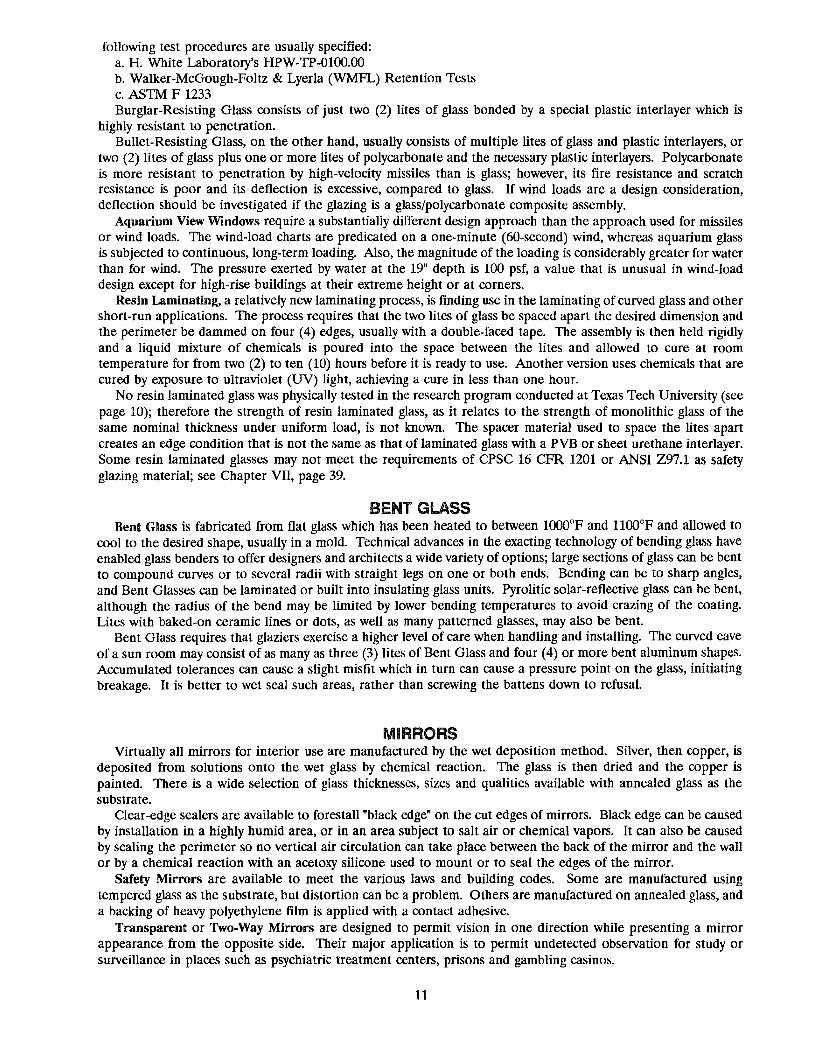
MIRRORS Virtually all mirrors for interior use are manufactured by the wet deposition method. Silver, then copper, is
deposited from solutions onto the wet glass by chemical reaction. The glass is then dried and the copper is painted. There is a wide selection of glass thicknesses, sizes and qualities available with annealed glass as the substrate.
Clear-edge sealers are available to forestall "black edge" on the cut edges of mirrors. Black edge can be caused by installation in a highly humid area, or in an area subject to salt air or chemical vapors. It can also be caused by sealing the perimeter so no vertical air circulation can take place between the back of the mirror and the wall or by a chemical reaction with an acetoxy silicone used to mount or to seal the edges of the mirror.
Safety Mirrors are available to meet the various laws and building codes. Some are manufactured using tempered glass as the substrate, but distortion can be a problem. Others are manufactured on annealed glass, and a backing of heavy polyethylene film is applied with a contact adhesive.
Transparent or Two-Way Mirrors are designed to permit vision in one direction while presenting a mirror appearance from the opposite side. Their major application is to permit undetected observation for study or surveillance in places such as psychiatric treatment centers, prisons and gambling casinos.
11
Two-Way Mirrors are manufactured by the same processes as those for solar-reflective glasses. The coated surface should be toward the "observed" side or room. The substrate can be clear glass, but bronze or gray is better because of lower "back reflectance."
A difference in lighting level is necessary between the observed side and the viewing side. In the room to be studied - the "observed side" - the lighting level must be at least five (5) times that on the viewing side; ten (10) times greater is even more effective. Additionally, bright, contrasting colors should be used in the observed room and dark, non-contrasting colors in the viewing room. The occupants in the viewing room should wear dark clothing.
First Surface Mirrors are mainly used for automotive rearview mirrors, copy machines, optical and scientific instruments, and similar uses unrelated to the construction industry. They are used where the refractive characteristic of glass cannot be tolerated. These first-surface uses are also a major application of chemically strengthened glass, usually due to the need for strengthening the surface of small sizes and thin substrates which are not amenable to heat-treating processes.
12

ASTM 1036, Standard Specification for Flat Glass, is the current standard for thickness, dimensional tolerances and characteristics for primary (annealed) flat glass. It replaces Federal Specification DD-G-451D, which has been withdrawn from use. Paragraph 4 from ASTM C 1036 classifies primary flat glass as follows:
4. Classification and Intended Use 4.1.2 Type II - Patterned and Wired Glass, Flat: 4.1 Types, Classes, Styles, Forms, Qualities and Class
Finishes - Glass shall be of the following types, 1 - Translucent classes, styles, forms, qualities and finishes, as 2 - Tinted heat-absorbing and light-reducing specified (see Section 5): (A and B applies to Class 2 only)
4.1.1 Type 1 - Transparent Glass, Flat: Style A - Higher light transmittance 4.1.1.1 Class 1 - Clear: Style B - Lower light transmittance
q I _ Mirror select q2 _ Mirror q3 _ Glazing select q4 _ Glazing A q5 _ Glazing B q6 _ Greenhouse
Quality
4.1.1.2 Class 2 - Tinted Heat-Absorbing and LightReducing: Quality q3 - Glazing select Quality q4 - Glazing A Quality q5 - Glazing B Style A - Higher light transmittance Style B - Lower light transmittance
4.1.1.3 Class 3 - Tinted, Light-Reducing:
q3 _ Glazing select q4 _ Glazing A q5 _ Glazing B
Quality
3 - Tinted, light-reducing
Form (Classes 1, 2, and 3) 1 - Wired, polished both sides 2 - Patterned and wired 3 - Patterned
q 7 - Decorative
q8 _ Glazing
Quality
Finish fl - Patterned one side f - Patterned both sides
Mesh (Forms 1 and 2) ml - Diamond m2 - Square m3 - Parallel strand m4 - Special
Pattern (Forms 2 and 3) pl_ Linear p2 _ Geometric p3 -Random p4 _ Special
ASTM C 1048, Standard Specification for Heat-Treated Flat Glass, is the current standard for heat-strengthened (Kind H.S.), fully tempered (Kind F.T.) and ceramic-coated spandrel glass. It replaces Federal Specification DD-G-1403C, which has been withdrawn from use. The Glass Tempering Association's Engineering Standards Manual is also a valuable reference for these products. ASTM C 1048 also deals with the application and testing of safety backing (scrim) to ceramic-coated spandrel glass. The Federal Construction Guide Specification has been withdrawn from use; therefore, Chapter 08110, which dealt with that subject, is no longer available.
Federal Standard CPSC 16 CFR 1201 has preempted portions of existing state and local safety glazing laws and codes pertaining to doors, patio doors, shower doors and tub enclosures. This standard, as well as ANSI Z97.1-1984 and local codes, should be checked by both the designer and the installer to ensure that any proposed choice or location of safety glazing materials is in compliance.
ASTM E 774, Standard Specification for Sealed Insulating Glass Units, is the current standard for insulating glass. It sets forth three levels of quality: Level C, Level CB and Level CBA ASTM E 773, Standard Test Method for Seal Durability of Insulating Glass Units, sets forth the testing procedures for sealed insulating glass units. ASTM E 54() and ASTM E 576 are the standard test methods for determining frost point/dew point of insulating glass units in the horizontal and vertical positions, respectively.
Federal Specification DD-M-4U prescribes the standards for mirrors and mirror frames. GSA and NAMM are cooperating on a revision of this standard, which was published in June 1990.
13

The tables on the following pages are those most commonly utilized from the preceding standards:
PRIMARY GLASS TABLE 1*
Dimensional Tolerance for Rectangular Shapes of Type 1 Transparent, Flat Glass
Thickness Tolerance
Thickness Range, Generally Available Nominal Length and Width
in the Following Designation, Traditional DeCimal, mm in. for Cut Sizes, plus Qualities
mm Designation in. min max min max or minus, mm (in.)
1.0 Micro-slide 0.04 0.79 1.24 0.031 0.049 1.6 ('A6) q4, q5 1.5 Photo 0.06 1.27 1.78 0.050 0.070 1.6 ('A6) q4, q5 2.0 Picture 0.08 1.80 2.13 0.071 0.084 1.6 ('A6) q4, q5
2.5 Single 0.09 2.16 2.57 0.085 0.101 1.6 ('A6) q', q2, q4, q5 2.7 Lami 0.11 2.59 2.90 0.102 0.114 1.6 ('A6) q4, q5 3.0 Double-% in. 0.12 2.92 3.40 0.115 0.134 1.6 ('A6) q', q2, q3, q4, q5, q6 4.0 %2 in. 0.16 3.78 4.19 0.149 0.165 1.6 ('A6) q3, q4, q5
5.0 3A6 in. 0.19 4.57 5.05 0.180 0.199 1.6 ('A6) q', q2, q3, q4, q5 5.5 7/32 in. 0.21 5.08 5.54 0.200 0.218 1.6 ('A6) q3, q4, q5 6.0 '/4 in. 0.23 5.56 6.20 0.219 0.244 1.6 ('A6) q', q2, q3 8.0 5/16 in. 0.32 7.42 8.43 0.292 0.332 2.0 (5!64) q3
10.0 % in. 0.39 9.02 10.31 0.355 0.406 2.4 (3!n) q3
12.0 % in. 0.49 11.91 13.49 0.469 0.531 3.2 (%) q3 16.0 % in. 0.63 15.09 16.66 0.595 0.656 4.0 (%2) q3 19.0 % in. 0.75 18.26 19.84 0.719 0.781 4.8 (3A6) q3 22.0 ?fa in. 0.87 21.44 23.01 0.844 0.906 5.6 (7/32) q3 25.0 1 in. 1.00 24.61 26.19 0.969 1.031 6.4 (%) q3 32.0 1% in. 1.23 28.58 34.93 1.125 1.375 7.9 (5A6) q3
*From ASTM C 1036, Table 2.
14
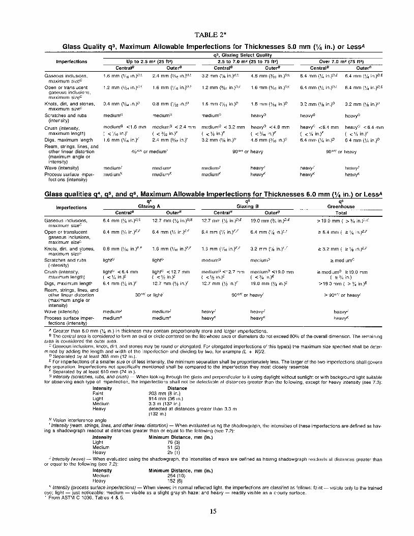
TABLE 2*
Glass Quality q3, Maximum Allowable Imperfections for Thicknesses 6.0 mm (% in.) or lessA
Imperfections
Gaseous inclusions, maximum sizec
Open or translucent gaseous inclusions, maximum sizec
Knots, dirt, and stones, maximum sizec
Scratches and rubs (intensity)
Crush (intensity, maximum length)
Digs, maximum length
Ream, strings, lines, and other linear distortion (maximum angle or intensity)
Wave (intensity)
Process surface imperfections (intensity)
Up to 2.5 m2 (25 f!2)
CentralB OuterB
1,6 mm ('/'6 in,)O,E 2.4 mm (3132 in,)D,E
1,2 mm (%4 in,)D,E 1,6 mm ('/,6 in,)D,E
0.4 mm ('/64 in,)O O,S mm ('/32 in,p
mediumG mediumG
mediumG <1,6 mm mediumG < 2.4 mm
( <'/,6 inY ( < 31a, inY 1,6 mm ('/,6 inY 2.4 mm (31a, inY
45 0H or medium'
mediumJ
mediumK mediumJ
mediumK
q3, Glazing Select Quality 2.5 to 7.0 m2 (25 to 75 f!2)
CentralB OuterB
3.2 mm (% in,)O,E 4.S mm (3/'6 in,)D,E
1,2 mm (3164 in ,)O,E 1,6 mm ('/'6 in,)D,E
1,6 mm ('/,6 in,)D 1,6 mm ('/,6 in,)D
mediumG heavyG
mediumG < 3,2 mm heavyG <4,S mm
«% inY ( <3/'6 inY 3,2 mm (% in,)D 4,S mm (3/'6 in,)D
90 0H or heavy
mediumJ
mediumK heavyJ
heavyK
Over 7.0 m2 (75 fF)
CentralB OuterB
6.4 mm (% in.)O,E 6,4 mm (% in,)O,E
6.4 mm (% in,)O,E 6,4 mm (% in,)O,E
3.2 mm (% in,)O 3,2 mm (% in,)O
heavyG heavyG
heavyG <6.4 mm
( <%inY 6.4 mm (% in,)D
heavyG < 6,4 mm
( <'/4 inY 6,4 mm (% in,)O
90 0H or heavy
heavyJ
heavyK
heavyJ
heavyK
Glass qualities q4, q5, and q6, Maximum Allowable Imperfections for Thicknesses 6.0 mm (% in.) or lessA
~ ~ ~ Imperfections Glazing A Glazing B Greenhouse
CentralB OuterB CentralB OuterB Total
Gaseous inclusions, maximum sizec
Open or translucent gaseous inclusions, maximum sizec
Knots, dirt, and stones, maximum sizec
Scratches and rubs (intensity)
Crush (intensity, maximum length)
Digs, maximum length
Ream, strings, lines, and other linear distortion (maximum angle or intensity)
Wave (intensity)
Process surface imperfections (intensity)
6.4 mm (% in.)D,E
6.4 mm (% in.)E,F
O.S mm ('/32 in.)E,F
lightG
lightG < 6,4 mm ( < % in.)E
6.4 mm (% in.)E
12.7 mm (% in.)D,E
6.4 mm (% in.JE-F
1.6 mm ('/'6 in.)E,F
lightG
IightG < 12,7 mm ( <% in.)E
12.7 mm (% in.)E
30 0H or light'
mediumJ mediumJ
mediumK mediumK
12.7 mm ('12 in.)D,E
6.4 mm (% in.)E,F
1.6 mm ('/'6 in.JE-F
mediumG
mediumG <12.7 mm «% in.)E
12.7 mm {,/, in.)E
19,0 mm (314 in.)D,E
6.4 mm (% in.)E,F
3.2 mm ('/s in.)E,F
mediumG
mediumG <19.0 mm ( <% in.)E
19.0 mm (% in.)E
90 0H or heavy'
heavyJ
heavyK heavyJ
heavyK
A Greater than 6.0 mm (% in.) in thickness may contain proportionally more and larger imperfections.
> 19,0 mm ( > % in,)D,E
2: 6,4 mm ( 2: % in,)E,F
2: 3,2 mm ( 2: % in.JE-F
2: mediumG
2: mediumG 2: 19,0 mm ( ;,:% in.)
>19,Omm( >%in.)E
> 90 0H or heavy'
heavyJ
heavyK
B The central area is considered to form an oval or circle centered on the lite whose axes or diameters do not exceed SO% of the overall dimension. The remaining area is considered the outer area.
C Gaseous inclusions, knots, dirt, and stones may be round or elongated. For elongated imperfections of this type(s) the maximum size specified shall be determined by adding the length and width of the imperfection and dividing by two, for example (L + W)/2. ° Separated by at least 305 mm (12 in.). E For imperfections of a smaller size or of less intensity, the minimum separation shall be proportionately less. The larger of the two imperfections shall govern
the separation. Imperfections not specifically mentioned shall be compared to the imperfection they most closely resemble, F Separated by at least 610 mm (24 in.). G Intensity (scratches, rubs, and crush) - When looking through the glass and perpendicular to it using daylight without sunlight or with background light suitable
for observing each type of imperfection, the imperfections shall not be detectable at distances greater than the following, except for heavy intensity (see 7.3): Intensity Distance Faint 203 mm (8 in.) Light 914 mm (36 in.) Medium 3.3 m (132 in.) Heavy detected at distances greater than 3.3 m
(132 in.) H Vision interference angle 'Intensity (ream, strings, lines, and other linear distortion) - When evaluated using the shadowgraph, the intensities of these imperfections are defined as hav
ing a shadowgraph readout at distances greater than or equal to the following (see 7.2):
Intensity Light Medium Heavy
Minimum Distance, mm (in.) 76 (3) 51 (2) 25 (1)
J Intensity (wave) - When evaluated using the shadowgraph, the intensities of wave are defined as having shadowgraph readouts at distances greater than or equal to the following (see 7.2):
Intensity Minimum Distance, mm (in.) Medium 254 (10) Heavy 152 (6)
K Intensity (process surface imperfections) - When viewed in normal reflected light, the imperfections are classifed as follows: faint - visible only to the trained eye; light - just noticeable; medium - visible as a slight grayish haze; and heavy - readily visible as a cloudy surface. * From ASTM C 1036, Tables 4 & 5.
15

TABLE 3* Thickness and Tolerance for Patterned Glass Patterns pi to p3
Tolerance, Thickness, mm (in.) Cut Size Thickness Designation,
mm (in.) max min Tolerance, Length and Width,
plus or minus, mm (in.) 2.5 (88) 3.0 (D8) 3.2 (118) 4.0 (%2) 4.8 (3/16) 5.6 (1/32) 6.4 (%) 7.9 (5/16) 9.5 (%)
*From ASTM C 1036, Table 9.
2.8 (0.110) 3.4 (0.134) 4.4 (0.172) 4.4 (0.172) 5.6 (0.219) 6.8 (0.266) 7.6 (0.297) 9.1 (0.359)
10.7 (0.422)
2.2 (0.085) 2.8 (0.110) 2.8 (0.110) 3.6 (0.142) 4.4 (0.172) 5.2 (0.203) 6.0 (0.234) 7.1 (0.281) 8.7 (0.344)
Note: Thicknesses greater than 7/32" are available only from foreign sources.
TABLE 4* Thickness and Tolerance for Wired Glass
Thickness Designation, mm (in.f
Tolerance, Thickness, mm (in.)
5.6 (1/32)A 6.4 (%) 9.5 (%)
max 6.4 (0.250) 7.6 (0.297) 9.9 (0.391)
A Never approved by Undetwriter's Laboratories for fire resistance. *From ASTM C 1036, Table 8. Note: The 3/8" thickness is available only from foreigh sources.
min 5.1 (0.203) 6.4 (0.250) 8.3 (0.328)
TEMPERED, HEAT-STRENGTHENED & SPANDREL GLASS Flatness: (a) Localized Warp; 1/16" (1.6mm) maximum in anyone foot (305mm) span. (b) Any localized kink
centered at any tong location shall not exceed 1/16" (1.6mm) over a 2" (51mm) span. (c) Overall Bow and Warpage Tolerances for flat tempered glass are measured while the glass is placed in a free-standing vertical position, resting on supports at the quarter points. With the glass in this position, place a straight edge parallel to the concave edge of the glass within 1" of the edge of the glass horizontally along the upper edge. Measure the maximum deviation with a taper or feeler gauge or a dial indicator micrometer. Values of maximum allowable bow are shown in Table 5.
1/8"-5/32" Length of Edge 3/16"
0- 18" 1/8"
18 - 36" 3/16"
36 - 48" 9/32"
48- 60" 3/8" 60- 72" 1/2"
72- 84" 5/8"
84 - 96" 3/4"
96 - 108" 7/8"
108 - 120" 1"
120 - 132"
132 - 144"
144 - 156"
From ASTM C 1048, Table 2
TABLE 5 Overall Bow Allowance
Tempered, Heat-Strenl!thene dG lass NOMINAL GLASS THICKNESS
7/32" 1/4" 5/16"
3/32" 1/16" 1/16"
5/32" 1/8" 3/32"
7/32" 3/16" 5/32"
5/16" 9/32" 7/32"
7/16" 3/8" 9/32"
9/16" 1(2" 11/32"
11/16" 5/8" 7/16"
13/16" 3(4" 9/16"
15/16" 7/8" 11/16"
1-1/16" 1" 13/16"
1-3/16" 1-1/8" 15/16"
1-5/16" 1-1/4" 1-1/16"
16
3/8" 1/2"-7/8"
1/16" 1/16"
3/32" 1/16"
1/8" 3/32"
3/16" 1/8"
1/4" 3/16"
5/16" 1/4"
3/8" 9/32"
1/2" 3/8"
5/8" 1/2"
3/4" 5/8"
7/8" 3/4"
1" 7/8"

TABLE 6* Dimensional Tolerances
Tempered, Heat-Strengthened & Spandrel Glass
DIMENSIONS PLUS
Transparent Glass & Coated Glass Conditions A & C
Neither Dimension over 76" 1/16"
With one or more dimensions from 76"-96" 1/16" and not over 40 sq. ft. in area 1/16"
Either dimension over 96" or over
4a sq. ft. in area 1/16" Spandrel Glass one surface ceramic coated Condition B
Dimensions not over 96" 0
Dimensions over 96" a
*Compiled from ASTM C 1048
TABLE 7 Strips - Definition & Dimensional Tolerance
MINUS
1/8"
1/8" 3/16"
3/16"
3/16"
1/4"
TOLERANCE DEFINITION Condition A & C Condition B
LENGTH WIDTH Plus Minus Plus Minus
Up to 72" equal to or less than the length
divided by 8 1/8" 1/8" a 3/16"
72" to 96" equal to or less than the length
divided by 7
96" to 132" equal to or less than the length
divided by 5 3/16" 3/16" a 1/4"
Compiled from ASTM C 1048 Note: The length-to-width ratio of strips may be increased by substituting thicknesses greater than 6mm (1/4").
17

ASTM C 509 ASTM C 510 ASTM C 716 ASTM C 794 ASTM C·864 ASTM C 962 ASTM C 964 ASTM C 1036 ASTM C 1048
ASTM C 1087
ASTM C 1115 ASTM E 90 ASTM E 283 ASTM E 330
ASTM E 331
ASTME 336 ASTME 413 ASTME 488 ASTME 514 ASTME 546 ASTME 547
ASTM E 576 ASTM E 754 ASTM E 773 ASTM E 774 ASTM E 783 ASTM E 894 ASTM E 966 ASTM E 987 ASTM E 997
ASTM E 998
ASTM E 1017 ASTM E 1105
ASTM E 1233
ASTM E 1300 ASTM F 1233 ASTM STP 1054 ASCE 7-88 ANSI Z 97.1 AAMA 101-88 AAMA502-90 AAMA 1503.1-88
AAMA 1504-88 AAMA 1600-90 AAMACW-I-9 AAMACW-11 AAMACW-12 AAMACW-13 AAMA CWG-1-89 AAMAMCWM-1 AAMA TIR-A7-87 AAMAGDSG-l AAMASFM-1
SUGGESTED FILE OF REFERENCE MATERIALS
Standard Specification for Cellular Elastomeric Preformed Gasket and Sealing Material Standard Test Method for Staining and Color Change of Single- or Multicomponent Joint Sealants Standard Specification for Installing Lock-Strip Gaskets and Infill Glazing Materials Standard Test Method for Adhesion-in-Peel of Elastomeric Joint Sealants Standard Specification for Dense Elastomeric Compression Seal Gaskets, Setting Blocks, and Spacers Standard Guide for Use of Elastomeric Joint Sealants Standard Guide for Lock-Strip Gasket Glazing Standard Specification for Flat Glass (Replaced DD-G-451d) Standard Specification for Heat-Treated Flat Glass-Kind HS, Kind FT Coated and Uncoated Glass
Replaced DD-G-1403 (b) and (c) Standard Test Method for Determining Compatibility of Liquid-Applied Sealants with Accessories Used in Structural
Glazing Systems Standard Specification for Dense Elastomeric Silicone Rubber Gaskets and Accessories Standard Test Method for Laboratory Measurement of Airborne Sound Transmission Loss of Building Partitions Standard Test Method for Rate of Air Leakage Through Exterior Windows, Curtain Walls, and Doors Standard Test Method for Structural Performance of Exterior Windows, Curtain Walls, and Doors by Uniform Static Air
Pressure Difference Standard Test Method for Water Penetration of Exterior Windows, Curtain Walls, and Doors by Uniform Static Air
Pressure Difference Standard Test Method for Measurement of Airborne Sound Insulation in Buildings Classification for Rating Sound Insulation Standard Test Methods for Strength of Anchors in Concrete and Masonry Elements Standard Test Method for Water Penetration and Leakage Through Masonry Standard Test Method for Frost Point of Sealed Insulating Glass Units Standard Test Method for Water Penetration of Exterior Windows, Curtain Walls, and Doors by Cyclic Static Air Pressure
Differential Standard Test Method for Frost Point of Sealed Insulating Glass Units in the Vertical Position Standard Test Method for Pullout Resistance of Ties and Anchors Embedded in Masonry Mortar Joints Standard Test Methods for Seal Durability of Sealed Insulating Glass Units Standard Specification for Sealed Insulating Glass Units Standard Method for Field Measurement of Air Leakage Through Installed Exterior Windows and Doors Standard Test Method for Anchorage of Permanent Metal Railing Systems and Rails for Buildings Standard Guide for Field Measurement of Airborne Sound Insulation of Building Facades and Facade Elements Standard Test Methods for Deglazing Force of Fenestration Products Standard Test Method for Structural Performance of Glass in Exterior Windows, Curtain Walls, and Doors Under the
Influence of Uniform Static Loads by Destructive Methods Standard Test Method for Structural Performance of Glass in Windows, Curtain Walls, and Doors Under the Influence
of Uniform Static Loads by Nondestructive Method Standard Specification for Generic Performance Requirements for Exterior Residential Window Assemblies Standard Test Method for Field Determination of Water Penetration of Installed Exterior Windows, Curtain Walls, and
Doors by Uniform or Cyclic Static Air Pressure Difference Standard Test Method for Structural Performance of Exterior Windows, Curtain Walls, and Doors by Cyclic Static Air
Pressure Differential Standard Practice for Determining the Minimum Thickness of Annealed Glass Required to Resist a Specified Load Impact Tests for Security Glazing Technology of Glazing Systems Minimum Design Loads for Buildings and Other Structures (Formerly ANSI A 58.1) Performance Specifications and Methods of Test for Safety Glazing Materials Used in Buildings Voluntary Specifications for Aluminum Prime Windows and Sliding Glass Doors Voluntary Specification for Field Testing of Windows and Sliding Glass Doors Voluntary Test Method for Thermal Transmittance and Condensation Resistance of Windows, Doors and Glazed Wall
Sections Thermal Performance of Windows, Doors and Glazed Walls Voluntary Specification for Skylights Aluminum Curtain Wall Design Guide Manual Design Wind Loads and Boundary Layer Wind Tunnel Testing Structural Properties of Glass Structural Sealant Glazing Systems Installation of Aluminum Curtain Walls Metal Curtain Wall Manual Sloped Glazing Guidelines Glass Design for Sloped Glazing Aluminum Store Front and Entrance Manual
18

~ ~ ~)
, JNl. 'SWBI7'~(ln: fit1lt\1IS~E:Su 8t ~~BE:~lt\I~ ,,' , "" '"' ~ "f' _ _ ~ '"
- ~ ~ -
SURFACE FINISHES ON GLASS Float glass has virtually plane and parallel surfaces by the nature of the process. The upper surface of the
ribbon, commonly called the "air" side, is fire-polished. The under side of the ribbon, called the "tin" side, usually can only be determined by lighting the glass with a special ultraviolet lamp.
Sheet glass and rolled glass are fire-finished on both surfaces. Polished wired glass has surfaces that have been mechanically ground and pOlished. The surface of glass is sometimes altered by sandblasting or acid etching to provide obscurity or decorative
effects. Sandblasting produces a relatively rough surface which tends to retain dirt and dust particles. Acid etching produces a finer surface than sandblasting.
The glass surface strength is depreciated by either process. Tempered glass should not be sandblasted or acid etched; the surface compression layer may be weakened or penetrated, causing spontaneous breakage. Deeply sandblasted glass should not be tempered or heat-strengthened.
LABELING Of fLOAT GLASS Because cutting and packing processes are highly automated at float glass plants, individual lites are no longer
labeled as standard practice. Shipment of large quantities of cut-to-size lites directly to a job site will generally be in 3000 lb. to 4000 lb. cases which have a label denoting the size, quantity and quality on one end of each case. Some producers will label individual lites of cut sizes if requested and if the quantities so warrant. There may be an extra charge involved.
Smaller quantities will generally be shipped to the job site as loose lites or in re-used cases. These will have been cut down at the glazier's warehouse from larger stock sizes. In this instance, a statement from the glazing contractor, stating that the glass meets the specifications, should be acceptable.
Tempered or heat-strengthened glass generally has a permanent logo identifying the fabricator etched in one corner.
Insulating glass, laminated glass and mirrors can readily be labeled, if so specified, with the manufacturer's name and quality of the glass used. Insulating glass certified by IGCC or other certification agenCies must have the certification number, date and manufacturer's identification mark either permanently etched on the glass or affixed to the spacer.
19

~~ '" ",," '"'). "' _ "i
~ c , ' ~,,"~. 1li)~$I~~ mm~$IIli)~IR~mllm~$, ' r w '" ~ " ~
, , ~ , ,
'"' ~ \ ~
GENERAL The reference data presented here is of a general nature and is for use as a design check or guideline. It is not
intended to replace the careful studies which are normally made for each project by the responsible design professionals.
Local building codes and federal and state regulatory agencies establish minimum design loads and safety glazing requirements for most structures. These regulatory stipulations should not inhibit investigation of their adequacy for a given project or portion of a project, using the most recently available data, criteria and techniques in conjunction with additional considerations. For tall buildings, buildings with an unusual shape or buildings exposed to unusual surroundings, wind tunnel tests are recommended as a means of establishing the probable, and frequently unusual, wind load forces on the building.
The tremendous increase in the cost of energy since 1973 has promoted heat transfer design to virtually equal status with structural considerations. Various standards-writing and regulatory agencies have developed criteria to provide guidance and mandatory regulations regarding heat transfer. Intimate working knowledge of local and state energy codes is a vital requirement in building design. Glass products are available which can enable substantial heat transfer reduction without a corresponding reduction of glass area.
STRUCTURAL PERFORMANCE OF GLASS Any evaluation of the strength of glass must take into account its inherent structural characteristics. From an
engineering standpoint, glass is classified as a brittle material. It has no yield point and fractures suddenly. The stress level at failure may vary widely between nominally identical specimens. The stress level required to break a lite of glass is related to surface compression, fabrication, surface quality, support conditions, type and duration of loading, size, thickness, geometry, edge quality, age and service history.
Glass strength can only be expressed on a statistical basis. This requires testing of a large sample of a specific glass under a specific set of conditions. Twenty (20) nominally identical specimens would be considered the minimum number of test specimens; a much larger number conceivably could be required. Breakage results when a tensile component of stress exceeds the tensile strength of the specimen at a particular location. Fracture risk, while never entirely eliminated, usually can be reduced to an acceptable, practical level by appropriate selection by the design professional.
Figure 1 sets forth the statistical probability of breakage, in breaks per thousand, at various design factors for glass rigidly supported on four (4) sides when subjected to the initial occurrence of a 60-second uniform load.
FIGURE 1 Flat Glass Probability of Breakage*
Probability of Breakage* Annealed Glass Heat-Strengthened Tempered Glass at Initial Occurrence of (Coefficient of Glass (Coefficient (Coefficient of 6O-Second Desi~n Load Variation = 22%) of Variation = 15%) Variation = 10%)
(Breaks per 1000 loaded) Maximum Stress (PSI) Maximum Stress (PSI) Maximum Stress (PSI) 500 6,000 11,000 23,000 50 3,800 8,300 19,000 8 2,800 7,000 17,200 4 2,500 6,600 16,600 2 2,200 6,200 16,600 1 1,900 5,900 15,500
*For: A large number of lites with a statistically normal strength distribution; individual specimens will break at higher and lower levels.
In choosing glass for a structure having normal occupancy, the probable breakage rate of 8 per 1,000 is the factor that is commonly used. Industry design wind load charts are based on that factor unless otherwise stated. Should a lower probable breakage rate be desired for a particular structure, manufacturers' literature generally states a basis by which their chart can be adjusted to suit the specialized need.
20

IN-SERVICE EXPOSURES OF GLASS Various service conditions justify special considerations. These conditions may increase glass stresses. If they
are not considered, a glass may be selected which may not be adequate for the conditions. These conditions include the following:
a) Screens, eyebrows, louvers, shutters, etc., may increase or decrease wind loads and thermal stresses. b) Windbome roof gravel, hail and windbome debris may lead to surface damage, reduced strength and failure
under subsequent impact, wind load or thermal load. c) Severe temperature exposures, glazing stresses, sonic boom, seismic action, mechanical stresses from door
or window operation, pressure effects of air conditioning system operation, stack effects of ventilating systems and impact load such as that caused by window washing ladders or equipment, hose streams, etc., all may impose significant stresses.
When the effect of service conditions cannot be accurately predicted for the life span of the building, it is generally prudent to specify a lower probability of failure, i.e., 4, 2, or 1 lite per 1000.
DESIGN LOAD WIND LOAD
Figure 2, a 50-year recurrence Wind Velocity Map developed by the National Weather Service, is widely used to establish basic design wind loads for various purposes. Maps are also available for other recurrence periods such as lO-year, 30-year and lOO-year. The approach in collecting data for such maps is to measure the fastest average wind during finite time periods within each hour. Measurements obtained in this manner are known as the "fastest mile of wind" because the procedure is to actually measure the time required for a mile-long sample of air to pass a fixed point. The time duration is given by the equation: t= 3600/v where t is the time in seconds and V is the wind velocity in miles per hour, for the mile-long sample to pass the fixed-point measuring device or station.
The relationship between wind velocity and wind pressure is found in Ensewiler's Formula: P=.00256V2 where P is the wind pressure in pounds per square foot exerted on a flat surface normal to the wind direction and V is the wind velocity in miles per hour. The following is a more convenient, rounded-off expreSSion which is accurate within 1.2%: V2 = 400p.
FIGURE 2 WIND VELOCITY MAP
SCALE I: 20':000 000
i " It X 1\( (110..... i CULF' ill. 1" ~ ~ ~t3-Balslc wincf-sp~;d 70 mph e\speCi81 wind region i
Notes: 1. Values are fastest-mile ~peeds at 33 ft.(10m) above ~round for exp~sure : category C and are associated with an annual probability of 002.
2. Linear interpolation between wind speed contours is acceptable. 3. Caution in the use of wind speed contours in mountainous regions of
Alaska is :dVised. l L
Basic Wind Speed (miles per hour)
21

After establishing the wind load for a particular project, a number of other factors that influence the final design load figure should be considered: (a) type of exposure; (b) building height; (c) building shape and orientation; (d) wind gusting; (e) windborne missiles; and (1) sloped glazing and/or skylights.
lYPE OF EXPOSURE Four types of exposure are considered in ANSI AS8.1-19823
1. Exposure A. Large city centers with at least 50% of the buildings having a height in excess of 70 feet. Use of this exposure category shall be limited to those areas for which terrain representative of Exposure A prevails in the upwind direction for a distance of at least one-half mile or 10 times the height or the building or structure, whichever is greater. Possible channeling effects or increased velocity pressures due to the building or structure being located in the wake of adjacent buildings shall be taken into account.
2. Exposure B. Urban and suburban areas, wooded areas or other terrain with numerous closely spaced obstructions having the size of single family dwellings or larger. Use of this exposure category shall be limited to those areas for which terrain representative of Exposure B prevails in the upwind direction for a distance of at least 1,500 feet or 10 times the height of the building or structure, whichever is greater.
3. Exposure C. Open terrain with scattered obstructions having heights generally less than 30 feet. This category includes flat, open country and grasslands.
4. Exposure D. Flat, unobstructed coastal areas directly exposed to wind flowing over large bodies of water. This exposure shall be used for those areas representative of Exposure D extending inland from the shoreline a distance of 1,500 feet or 10 times the height of the building or structure, whichever is greater.
The ANSI standard also makes reference to increased pressures (or suctions) that can occur from channelization of wind by nearby buildings and obstructions. Also see "Windborne Missiles."
BUILDING HEIGHT It has long been known that wind velocity increases with height above ground level and that the rate of increase
is related to the type of terrain over which the wind flows. The increase is not a straight-line relationship to the height nor is it a proportional relationship to the height. Figure 3 illustrates the velocity/height relationship to effective wind pressures for one type of terrain.
FIGURE 3 Effective Wind Pressures (psi), Open Terrain'" Height Basic Wind Speed (mph)
above grade 70 80 90 100 no 120
30 ft. 12.5 16.4 20.7 25.6 31.0 36.9 50 ft. 14.5 19.0 24.0 29.6 35.8 42.6 75 ft. 16.3 21.3 27.0 33.3 40.3 47.9
100 ft. 17.7 23.1 29.3 36.1 43.7 52.0 150 ft. 19.9 25.9 32.8 40.5 49.0 58.2 200 ft. 21.6 28.2 35.7 44.0 53.3 63.4 250 ft. 23.0 30.0 38.0 46.9 56.8 67.6 300 ft. 24.2 31.6 40.0 49.4 59.8 71.2 375 ft. 25.8 33.7 42.7 52.7 63.8 75.9 450 ft. 27.2 35.5 45.0 55.6 67.2 79.9 550 ft. 28.8 37.6 47.6 58.8 71.1 84.6 750 ft. 31.5 41.1 52.0 64.2 77.7 92.5 1000 ft. 34.2 44.6 56.5 69.7 84.4 100.4
*NOTE: For more extensive information, refer to ANSI AS8.1 for other types of terrain.
'The American Society of Civil Engineers (ASCE) will publish ASCE 7-88 in September 1990. That document will then supersede ANSI AS8.1-1982. There may be some minor changes that will affect AS8.1 references in this manual.
22
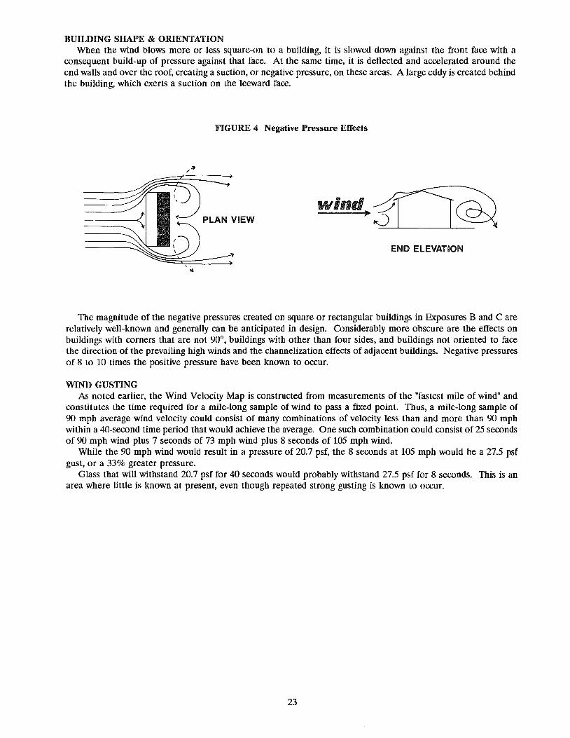
BUILDING SHAPE & ORIENTATION When the wind blows more or less square-on to a building, it is slowed down against the front face with a
consequent build-up of pressure against that face. At the same time, it is deflected and accelerated around the end walls and over the roof, creating a suction, or negative pressure, on these areas. A large eddy is created behind the building, which exerts a suction on the leeward face.
FIGURE 4 Negative Pressure Effects
PLAN VIEW
END ELEVATION
The magnitude of the negative pressures created on square or rectangular buildings in Exposures Band Care relatively well-known and generally can be anticipated in design. Considerably more obscure are the effects on buildings with corners that are not 90°, buildings with other than four sides, and buildings not oriented to face the direction of the prevailing high winds and the channelization effects of adjacent buildings. Negative pressures of 8 to 10 times the positive pressure have been known to occur.
WIND GUSTING As noted earlier, the Wind Velocity Map is constructed from measurements of the "fastest mile of wind" and
constitutes the time required for a mile-long sample of wind to pass a fixed point. Thus, a mile-long sample of 90 mph average wind velocity could consist of many combinations of velocity less than and more than 90 mph within a 40-second time period that would achieve the average. One such combination could consist of 25 seconds of 90 mph wind plus 7 seconds of 73 mph wind plus 8 seconds of 105 mph wind.
While the 90 mph wind would result in a pressure of 20.7 psf, the 8 seconds at 105 mph would be a 27.5 psf gust, or a 33% greater pressure.
Glass that will withstand 20.7 psf for 40 seconds would probably withstand 27.5 psf for 8 seconds. This is an area where little is known at present, even though repeated strong gusting is known to occur.
23

WIND BORNE MISSILES Current design standards and codes acknowledge the existence of small missile impacts upon building facades
but do not contain specific guidance for the designer. The missiles consist of roofing stones and other urban debris that become windborne.
Investigations at the Institute for Disaster Research at Texas Technical University indicate that a 0.2 oz. (6.0 gm) roofing stone can, within a distance of 70 feet, attain a velocity of 35 mph in an 80 mph wind. Furthermore, this 35 mph velocity is sufficient to break many thicknesses of annealed glass.
Negative wind pressures can readily lift stones and other debris from roofs and inject them into the wind stream. Gravity will cause the stones to assume a curved trajectory, and they will be caught by winds channelized between buildings. The velocity of wind channelized between buildings can be substantially greater than the wind velocity registered at a recording station for the general area.
Figure 5 shows the distance required to impart a given velocity to an 0.2 oz. (6.0 gm) roofing stone when impelled by 80 mph, 100 mph and 120 mph winds. Figure 6 is a chart of missile velocities that may cause glass breakage. Velocities are expressed in feet/second and mph. To convert feet/second to mph, multiply by 0.68. It is feet per second, expressed by substituting the "f' for "per".
Impact velocities obtained from Figure 5 can be compared to impact velocities causing breakage in Figure 6 to determine if glass breakage is likely. If glass breakage could occur, consider using the next stronger glass of the same thickness or laminated glass. The latter tends to remain in the opening following breakage.
200
150
100
eo
~7Q u.
60
~ 50
u
~ 40
~ 35
30
20
15
10
10
FIGURE 54
DISTANCE, FT
15 20 30 40 60 70 100 150 200 300 500 700 1000
4"Designing for Windborne Missiles in Urban Areas" by Joseph E. Minor, W. Lynn Beason and Phillip L. Harris, Journal of the Structural Division, #14143, November 1978, American Society of Civil Engineers, pages 1756-57.
24

FIGURE 6(1)
Roof Gravel" Impact Velocities Causing Breakage in Monolithic Glass
Glass Annealed Heat Strengthened Tempered
Thiclrness fl./sec. mph ft./sec. mph fl./sec. mph
3/16" 30 20 65 44 1/4" 30 20 35 24 65 44
5/16" 30 20 65 44 3/8" 35 24 60 41 1/2" 40 27 50 34 3/4" 55 37 55 37
*6 gram gravel IA Design Guide to the Structural Performance of Laminated Architectural Glass, Monsanto Chemical Company, page 21. The guide was prepared by the Glass Research & Testing Laboratory, Texas Tech University. Project manager was Dr. Joseph E. Minor, P.E.
SLOPED GLAZING
Inward and outward sloping of partial or entire building facades evolved from skylights. "Sloped Glazing," the modern-day terminology for fenestration that slopes more than 15° from the vertical, has attained tremendous popularity in all types of building construction. The sloped glazing system must entail a broader range of design considerations than the conventional window, store front or curtain wall system. Some of the most prevalent considerations follow:
1. Due to the great degree of solar energy exposure, both the glass and metal framing system must be carefully engineered to accommodate differential thermal stresses and opposing building reactions.
2. The various geometric shapes and geographic locations require that live loads and wind loads be analyzed in combination (i.e., positive-negativelwindward-Ieeward) and in accordance with state and local building codes.
3. Good effective drainage of both condensation and water infiltration is essential. The glazing rabbet must be drained into a gutter, and the gutter must freely allow water to exit to the exterior. Sealants alone cannot prevent water infiltration in the long term. Generally speaking, conventional window or curtain wall systems will not perform adequately, in this respect, when installed in a sloped configuration.
4. Conversely, the drainage systems of sloped glazing systems generally do not function well when installed in a vertical position.
5. Horizontal caps must be designed to allow proper and complete runoff of water. If not, glass staining and premature failure of insulating glass will result.
The design and selection of glass for skylights and sloped glazing requires special attention for a number of reasons:
1. Sloped glass is more susceptible to impact from falling Objects, windborne debris and missiles than vertical glass.
2. Sloped glazing, in most cases is more likely to fall from the opening when it breaks than is vertical glass. Good design indicates that the choice of glass must be based on eliminating or minimizing, to the degree practical, any potential hazards.
3. Snow loads, unlike wind and live loads, may be imposed on the glazing for extended periods; strength of glass and contribution of the plastic interlayer in laminated glass are both time dependent, i.e., under longterm loading, the strength of these materials is less than under instantaneous loading, such as wind.
4. If the sloped glazing is close to walk-ways, consideration must be given to snow sliding off or water cascading off, striking pedestrians and potentially causing injury.
5. For most orientations, the temperature sloped glass may reach can be substantially higher than for vertical glazing due to the solar radiation being more nearly normal to the glass surface, plus the stratification of warm air under the glass. Consequently, the thermal stresses created usually require heat treated glass.
Many sloped glazing systems have progressed from the conventional cap glazing system to the two-sided structural silicone technique. With a cap glazing system, each edge of the glass lite is retained with a metal glazing cap. This type of system usually experiences a greater amount of water infiltration due to the damming caused by the purlin cap and butt-jointed corner intersections with the sloping rafter caps.
25

Two-sided structural silicone glazing systems are usually field glazed and are used extensively for low-pitched and segmented vault application. The flush purlin detail (Figure 7) minimizes water and dirt retention. Usually, the two sloping edges of a glass lite, which are supported by the rafters, are retained with glazing caps. The two adjacent or horizontal edges are secured to the purlin using a structural silicone joint which is normally applied from the exterior. It is important to note that for two-sided silicone glazing systems, an insulating glass unit must be structurally retained on all sides. Although two-sided silicone glazing systems reduce the amount of water infiltration, good design practice should incorporate a mechanical gutter system to control water infiltration and condensation. Refer to Chapter IX under "Structural Silicone Glazing Systems" for compatibility testing and adhesion testing procedures that must be followed to assure a proper installation.
FIGURE 7
Proper glass selection is probably the single most important consideration when dealing with a sloped glazing system. Factors such as the life safety resulting from glass fallout after breakage and the potential liability for the owner, architect, glass and skylight manufacturers, and glazing contractor must be carefully considered. Currently the major building codes are not in agreement regarding the type of glass that should be used in sloped glazing. Additionally, each code differentiates between commercial greenhouses, commercial buildings, and residential single and multi-family dwellings. Compliance with the applicable code is essential for each installation.
From the standpoint of public liability as well as code compliance, it would appear that heat-strengthened (4500 psi to 7000 psi surface compression) laminated glass is a safe selection, either alone or as the inner lite of an insulating unit whose outer lite is tempered. Such a configuration would meet or exceed all current (1990) codes for all applications.
GLASS THICKNESS SELECTiON
After full consideration and summation of the many variables when computing the design load on the glass for a specific project, a wind load chart published by one of the several glass producers may be used. There are differences between the various wind load charts, and the designer must decide which charts to use. Differences in the charts, although minor, can be attributed, at least in part, to the basic assumptions, testing techniques and projections used in the in-house development of the charts.
All glass framing systems are not alike and may not be like the test frame used by a given glass producer in the development of their wind load charts. Reference to ASTM E 997, "Standard Test Method for Structural Performance of Glass in Exterior Windows, Curtain Walls and Doors Under the Influence of Uniform Static Loads by Destructive Methods," might be advisable. It sets forth the test procedure for determining the probability of failure in glass framing systems that are at variance from the standard rigid frame employed by glass producers. ASTM E 998 is a companion, non-destructive method of test.
26
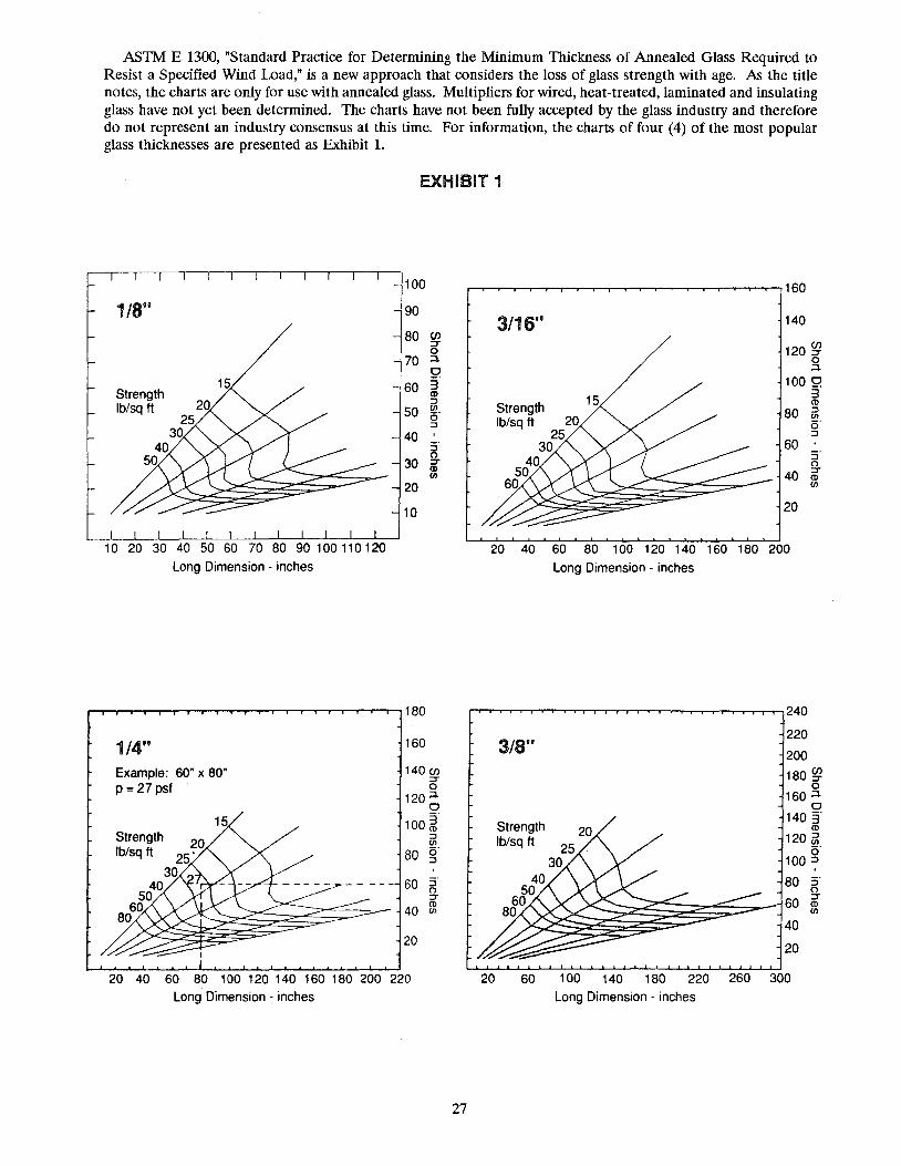
ASTM E 1300, "Standard Practice for Determining the Minimum Thickness of Annealed Glass Required to Resist a Specified Wind Load," is a new approach that considers the loss of glass strength with age. As the title notes, the charts are only for use with annealed glass. Multipliers for wired, heat-treated, laminated and insulating glass have not yet been determined. The charts have not been fully accepted by the glass industry and therefore do not represent an industry consensus at this time. For information, the charts of four (4) of the most popular glass thicknesses are presented as Exhibit 1.
EXHIBIT 1
1/8"
Strength Ib/sq ft 20
25 30
40 50
1 0 20 30 40 50 60 70 80 90 1 00 11 0 1 20
Long Dimension - inches
1/4" Example: 60" x 80" p = 27 psf
Strength 20 Ib/sq ft 25'
30 40
50 60
80
,100
r 80 (J) ::r 0
J70 ~
0 3"
,60 <D :::l (JJ 50 0" :::l
40 :r 0
30 ::r <D (JJ
20
10
180
160
140 (J) ::r 0
120 ;:::!. 0
100 ~" :::l (JJ
80 0" :::l
60 S" 0 ::r <ll
40 (JJ
20
20 40 60 80 100 120 140 160 180 200 220 Long Dimension - inches
27
3/16"
Strength Ib/sq ft
25 30
40 50
60 ~~~~~::::=--
140
120 g? o ;:::!.
100 9. 3 <ll
80 ~ 0" :::l
60 ' S" o
40 ~ (JJ
20
~ ~ W M 100 1~1~ lW1M2oo Long Dimension - inches
20
3/8"
Strength Ib/sq ft
40 50
20 25
30
60~~~~~~_~ 80 ?
240
220
200
180 g? 0
160 ;:::!. 0
1403" <ll
120 ~ 0"
100 :::l
80 S" 0
60 ::r <ll (JJ
40
20
60 100 140 180 220 260 300 Long Dimension - inches

All of the glass wind load charts are based on the breaking strength of glass and a probability-of-breakage factor, usually 8 lites per 1000. Often deflection is overlooked or ignored, but it should be addressed. Excessive deflection can cause poor performance of glazing gaskets or tapes, glass-to-metal contact which can cause breakage, as well as serious psychological problems among personnel.
Heat strengthening or tempering will not change the deflection characteristic of glass (Modulus of Elasticity); it only changes the breaking strength (Modulus of Rupture).
Large bUildings, buildings in an urban environment and those of unusual shape should have the design wind load confirmed or established by testing. Three methods commonly used are the ASTM static or dynamic structural tests of a full-size mockup or a boundary layer wind tunnel test. All are adequately described in available literature.
While the glass manufacturers have appropriate data for determining performance of their products, it still remains the responsibility of the design professional to review those performance criteria and determine if they are suitable for his intended application for the specific project in hand.
ENERGY TERMINOLOGY &: HEAT TRANSFER A major function of tinted glass, solar reflective coatings, Low-E coatings, insulating glass and gas filling is to
reduce the solar heat gain/loss through windows, curtain walls and skylights while admitting an acceptable amount of daylight.
U-Value is the overall coefficient of heat transmission, or thermal conductance (air-to-air) of a material or combination of materials, across which there is a temperature differential. The heat loss (or gain) of any fenestration, expressed in Btu/hr./sq. ft., is the result of multiplying the V-Value times the difference between the outdoor and indoor temperatures.
V-Value is customarily expressed as the "center of glass" value. The area within 2.5" of the edge of the glass will have a somewhat higher V-Value due to the influence of the spacer material and, to some extent, the framing material.
TABLE 8 Winter U-Value Comparisons
1.03-1.07 1.0
.87-.97 0.9
0.8
0.7 .60-.661
0.6
0.5 .48-.522
0.4 .30-.42 .38-.48
0.3 .31-.35 .23-.25
0.2
0.1 Low·E Argon Low-E Air Reflective Reflective Clear and Monolithic Monolithic Filled Filled Argon Filled Air Filled Tinted Air Reflective Uncoated LG. Units LG. Units LG. Units LG. Units Filled Glasses Glasses
LG. Units
Shading Coefficient is the ratio of the solar heat gain through a specific fenestration to the solar heat gain through a lite of 1/8" clear glass. Since the shading coefficient of 1/8" clear glass is 1.00, the shading coefficient of any other fenestration will be less than 1.00, except that of a thinner, clear glass, which can be greater than 1.00. Thus:
S.c. = Solar Heat Gain of The Fenestration in Question -------------------------------------------------------------------
Solar Heat Gain of 1/8" Clear Glass
IVnits 112" to 5/8" overall thickness, with 1/4" air space. 2Vnits 7/8" and greater overall thickness, with 112" air space.
28

A table of "Solar Heat Gain Factors" is published in the ASHRAE5 Handbook of Fundamentals. The values are those transmitted by a 1/8" clear glass in a vertical position for the 16 compass points listed. The chapter containing the tables also presents formulae for calculation of actual solar intensity, solar heat gain for sloped surfaces and many other aspects of glazings.
For comparison purposes only, virtually all glass producers and fabricators include a "Relative Heat Gain" column in the tables listing the various properties of their respective glass products. This particular column presents the sum of the V-Value and shading coefficient calculations based on a summer temperature outdoor/indoor difference of 14°F and a solar heat gain factor of 200 Btu!hr'/sq.ft.
TABLE 9 RANGE" OF GLASS PERFORMANCE
Coating Daylight 1/4" Monolithic 1" Insulatinl! Color Transmittance S.c. V S.c. Air Filled V
Hi.gh Performance - Vacuum Deposition Silver 8% .21 - .28 .77 - .93 .10 - .22 .30 - .50
14% .29 - .35 .80 - .99 .12 - .30 .32 - .52 20% .36 - .41 .82 - 1.02 .16 - .34 .35 - .54
Golden 8% .17 - .27 .66 - .90 .10 - .18 .27 - .48 14% .20 - .34 .69 - .97 .12 - .24 .28 - .42 20% .24 - .40 .96 - 1.06 .14 - .28 .29 - .54
Earth Tone 8% .26 - .36 .86 - .92 .18 - .24 .42 - .51 14% .32 - .40 .92 - .98 .22 - .30 .43 - .53 20% .38 - .45 .98 - 1.03 .22 - .30 .32 - .55
Medium Performance - Pvrolitic Deoosition Silver 22 - 32% .44 - .52 1.08 - 1.11 .34 - .38 .49 - .56
Bronze 22 - 25% .45 - .52 1.07 - 1.11 .34 - .36 .49 - .56 Gray 18 - 20% .44 - .51 1.08 - 1.11 .40 - .44 .50 - .56
Green 29 - 33% .34 - .44 1.08 - 1.11 .34 - .38 .49 - .56 Blue 18 - 20% .36 - .43 1.07 - 1.12 .28 - .32 .49 - .57
Low-E - Vacuum De osition - #3 Surface Clear Glass 43 - 80% N.A N.A .40 - .82 .29 - .48
Tinted Glass 29 - 68% N.A N.A .26 - .55 .29 - .48 Low-E - Pvrolitic Deposition - Hil!h Performance
Clear Glass 73% .76 - .82 .34 Tinted Glass 39 - 63% .48 - .55 .34
Low-E - Pvrolitic Deposition - Medium Performance Clear Glass 73% .76 - .82 .39
Tinted Glass 41 - 63% .49 - .56 .39 Uncoated Glass
Clear Glass 88% .93 1.03 - 1.10 .80 .49 - .55 Tinted Glass 43 - 75% .69 - .71 1.03 - 1.10 .49 - .56 .49 - .55
*Values have been compiled from literature of several producers. Consult literature from manufacturer of your choice for specific values.
FollOwing are definitions of other commonly used terms:
R-Value: Thermal resistance of a glazing system expressed in FT2 /HRtF/BTU. It is the reciprocal of V-Value. The higher the R-Value, the less heat is transmitted through the glazing material.
Visible Light Transmission: In the visible spectrum (380 to 720 nanometers), the percentage of light that is transmitted through the glass.
Visible Light Reflectance: In the visible spectrum, the percentage of light that is reflected from the glass surface(s).
Solar Energy Transmittance: In the solar spectrum (300 to 2500 nanometers) the percentage of ultraviolet, visible and near infrared energy that is transmitted through the glass.
Solar Energy Reflectance: In the solar spectrum, the percentage of solar energy that is reflected from the glass surface(s).
5 American Society of Heating, Refrigeration and Air Conditioning Engineers
29
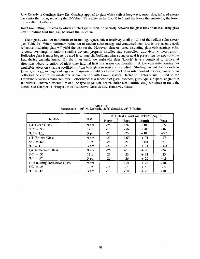
Low Emissivity Coatings (Low-E): Coatings applied to glass which reflect long-wave, room-side, infrared energy back into the room, reducing the U-Value. Emissivity varies from 0 to 1 and the lower the emissivity, the lower the resultant U-Value.
Inert Gas Filling: Process by which an inert gas is used in the cavity between the glass lites of an insulating glass unit to reduce heat loss, i.e., to lower the U-Value.
Clear glass, whether monolithic or insulating, rejects only a relatively small portion of the radiant solar energy (see Table 9). When maximum reduction of radiant solar energy and conducted heat loss is the primary goal, reflective insulating glass will yield the best result. However, clear or tinted insulating glass with awnings, solar screens, overhangs or indoor shading devices, properly installed and controlled, also deserve investigation. Reflective glass is most frequently used in commercial buildings where a major goal is preventing the entry of solar heat during daylight hours. On the other hand, low emissivity glass (Low-E) is very beneficial in residential situations where retention of night-time internal heat is a major consideration. A low emissivity coating has negligible effect on shading coefficient of the base glass to which it is applied. Shading control devices such as louvers, screens, awnings and window treatments should not be overlooked as solar control devices, passive solar collectors or controlled insulators in conjunction with Low-E glasses. Refer to Tables 9 and 10 and to the literature of various manufacturers. Performance is a function of glass thickness, glass type, air space, angle from the vertical, compass orientation and the type of gas (air, argon, sulfur hexafluoride, etc.) contained in the unit. Note: See Chapter II, "Properties of Reflective Glass & Low Emissivity Glass."
TABLE 10 December 21,40° N. Latitude, 40°F Outside, 70° F Inside
Net Heat Gain/Loss, BTU/hr./sq. ft. GLASS TIME North East South West
1/4" Clear Glass 9am -25 +92 +107 -25 S.C. = .93 12 n -17 -16 +202 -16 "U" = 1.10 3 pm -25 -25 +107 +92 1/4" Bronze Glass 9am -27 +60 +71 -27 S.C. = .69 12 n -21 -21 +141 -21 "U" = 1.10 3pm -27 -27 +71 +60 1/4" Reflective Glass 9 am -26 +18 + 26 -26 S.C. = .35 12 n -23 -23 + 61 -23 "un = .97 3pm -26 -26 + 26 +18 I" Insulating Reflective Glass 9am -10 +21 + 25 -10 S.C. = .25 12 n - 8 - 8 + 50 - 8 "U" = .42 3pm -10 -10 + 25 -10
30

,~, XlI. s~w~~ m~~~S'I\/II$SI~~:: '~"'"~o: ~,:, ~ ~~: ~ - \0 _ 'i "~J " "" ~~ ;;;-~ ., ~ ~",'
SOUND TRANSMISSION LOSS The ability of a material to minimize the passage of sound is referred to as sound transmission loss (TL). It
is expressed in decibels (dB). The 11.. of a material is measured by mounting a sample in an opening of a wall separating two reverberant test
rooms. Broad band sound is played into the first room (the source room). The difference between the sound levels in the source room and the second room (the receiving room) is defined as the noise reduction (NR). The wall separating the source room from the receiving room - the wall through which sound is transmitted - is called the common wall.
The NR is related to the TL but differs by a quantity related to the receiving room absorption and the area of the common wall. The arithmetic difference in decibels between the TL of a material and the NR resulting from its use typically falls in a range of + 5 dB, i.e., the 11.. and NR never differ by more than 5 dB.
It is important to note that 11.. is an intensive material property, i.e., it is related to its size and the circumstances surrounding its use. The NR is an extensive material property in that it is affected by the size and conditions surrounding a material's use, as well as its intensive property - 11...
SOUND TRANSMISSION LOSS CHARACTERISTICS OF MATERIALS The sound transmission loss (11..) performance of a material is dependent on its mass, damping and stiffness. One way to increase glass 11.. is to increase its thickness, i.e., mass. Changing glass stiffness would also help
but is not practical. (Glass stiffness should not be confused with glass strength, which refers to the resistance of glass to breakage.) An air space between two lites of glass also can increase sound isolation performance but only if the air space thickness is larger than that used conventionally in thermal insulating glass (generally 1{2" maximum for most sealed insulating glass configurations).
The only remaining variable is glass damping. Generally, glass has very low inherent damping. As shown below, using an interlayer to increase glass damping can result in 11.. increases, which otherwise can only be obtained through significant increases in glass thickness. Hence, in the domain of single thickness glass, laminated glazing offers several practical advantages.
When laminated glass is used in air-spaced or insulating glass configurations, the benefits of damping are even greater.
DAMPING Damping is the mechanical property of a material or system which quantifies the rate of dissipation of vibratory
motion into heat energy. A bell and a tuning fork are examples of systems with low damping. When they are struck, or excited, vibration persists or rings, resulting in sound that correspondingly persists. Note that ringing occurs at one discrete frequency in the case of the tuning fork and several discrete frequencies in the case of a bell.
The ringing or persistence of vibration can be diminished by holding the tuning fork tines or bell with one's hand. This acts to transfer the vibratory motion into heat energy which is dissipated in the hand. Although vibratory motion can be felt, producing a tingling sensation, the transfer of thermal energy is not perceptible.
Since glass has more damping than a tuning fork or bell, it does not display the same ringing characteristic. Nevertheless, the lack of damping in glass is usually sufficient to result in reduced sound isolation performance in certain frequency ranges. This reduced sound isolation performance is greatest at the critical frequency. At the critical frequency, sound is efficiently transmitted through an undamped material. Adding damping to glass increases the sound isolation performance of glass at critical frequency by reducing the transmission of sound at this frequency.
The most effective way for increasing the damping in glass is through the use of a viscous interlayer which is sandwiched between two pieces of glass. The bending waves in the glass excited by incident sound cause shearing strains within the viscous interlayer material. Because the interlayer material has inherently high damping, bending wave energy in the glass is then transformed into heat energy by the viscous interlayer.
SINGLE THICKNESS GLASS Because the sound transmission loss of all materials is frequency-dependent, it is most often presented as a one
third octave band frequency spectrum as indicated in Figure 1 for ~" monolithic glass and !in laminated glass. In Figure 1, the horizontal axis is frequency, and the vertical axis is TL. Notice that at frequencies below 1,000 Hz, the i" laminated glass TL is slightly higher than that for !in monolithic glass. In this frequency range, the TL
31

performance of these materials is dominated by their mass. Since the surface weights of both materials are nearly equal, only insignificant differences in TL are expected in this frequency range.
At about 2,500 Hz, the in monolithic glass TL drops significantly, while the i" laminated glass TL remains nearly level with frequency. At this frequency - the critical frequency - the bending wave speed in the glass is equal to the speed of sound in air. This results in efficient transmission of sound through the material, i.e., a low TL.
For plate materials, the critical frequency will vary with thickness, surface weight and stiffness. Comparing two materials of the same surface weight, the less stiff or "limp" material will have a higher critical frequency. The basic behavior of the TL above and below critical frequency in all single thickness, homogeneous materials is similar to that illustrated for i" glass.
AIR-SPACED GLASS The sound transmission loss (TL) characteristics of air-spaced glass (insulating glass) are considerably more
complicated than those for non-air-spaced (monolithic) glass. The differences between air-spaced and non-airspaced glass are illustrated in Figure 2. Figure 2 presents a comparison between TLs for in monolithic glass and ~n insulating glass composed of 1fs" monolithic glasstl" air space/1fs" monolithic glass. The comparison of these two configurations is interesting since they both have the same total surface weight, yet their TL performances are quite different.
As with monolithic glass, the sound isolation performance of insulating glass can be increased significantly through the use of laminated glass. Figure 3 presents a comparison between two types of 1" insulating glass, one using two lites of ~" monolithic glass and the other using two lites of i" laminated glass. The~" laminated glass consists of two lites of 1/8" monolithic glass laminated together with 0.030" PVB interlayer. As a reference, the TL for ~" monolithic glass is provided for comparison.
These three glazing configurations have nearly the same surface weight, but the combination of air space and damping interlayer results in a TL for the double laminated insulating configuration that is significantly higher than that for either standard insulating or equivalent monolithic glass.
SOUND TRANSMISSION GLASS Since sound transmission loss is frequency-dependent, it is generally reported in the 16 one-third octave
frequency bands between 125 Hz and 4,000 Hz. As a convenience, a rating method has been developed which allows a single value to be given to these 16 values, also referred to as a transmission loss spectrum. This rating is called the sound transmission class (STC), which has been defined in the American Society for Testing and Materials (ASTM) Standard E 413.
This standard defines a procedure for determining the STC value for a TL spectrum which involves fitting a contour to the one-third octave band TL spectrum. This contour is shown in Figure 4. Determining the STC for a material involves fitting this contour to the 16 one-third octave band TL values. This procedure is described in the ASTM standard.
It should be noted that the STC value has been developed to approximate the performance of a material in reducing the transmission of intelligible speech sound and other household sounds. The STC characterization of TL is useful for a quick comparison of materials, but it is not necessarily useful for assessing the performance of a material with respect to other non-speech sounds such as aircraft, highway traffic, train passbys, etc. For this purpose, it is necessary to consider octave or third octave band TL spectra. This analysis is normally performed by an acoustical engineer.
Figure 5 presents a table of STC values measured for several glazing configurations. Progressively higher STC values are noted with increasing mass and air space, and the use of laminating interlayer. Careful inspection of this data indicates the benefits of laminating and air-space thickness.
ACOUSTICAL GLAZING APPLICATIONS There are five major steps in selecting an acceptable acoustical glazing configuration for building windows.
Step I involves determining sound levels outside a building location. This sometimes involves measurements of sound levels. Other times, adequate information may be available from public agencies.
Step 2 involves determining the appropriate criteria for sound levels within the building. The exterior sound level determined in Step 1 minus the acceptable interior sound level determined in Step 2 produces the composite noise reduction. The composite noise reduction is the value of the sound isolation performance of the wall/window construction of a building. This value lies somewhere between the NR of the wall and the NR of the window. Usually, the wall NR is higher than the window NR.
32

Step 3 involves determining the noise reduction performance of the building exterior wall. The composite noise reduction determined in Step 2, together with the wall noise reduction determined in Step 3, can be used to determine the required window noise reduction.
Step 4 involves the analysis of the Step 3 window noise reduction to determine the corresponding sound transmission class (STC).
Step 5 involves selecting a glazing configuration which provides the required, or higher, STC rating and meets other building requirements. Data in Figure 5 can be used for this purpose.
Normally, acoustical consultants are employed to obtain noise measurements and perform the acoustical analysis needed to assist the architect or building owner in the selection of windows for a building project. However, a preliminary estimate of minimum required window STC for a building project can be determined through methodologies presented in various publications such as the Monsanto Acoustical Glazing Design Guide.
Many times, window specifications require the laboratory determination of STC for specific window models and sizes proposed for use in building projects. The use of an acceptable glazing configuration in a window system does not necessarily guarantee acceptable performance. Windows that fail to seal properly or windows with very lightweight frames may have a total sound isolation performance which is less than that of the glazing configuration when tested alone. Hence, laboratory certification of windows whose sound isolation performance is important to the success of a project should be based on laboratory tested sound isolation performance, i.e., STC.
It is essential that the entire exterior cladding, both walls and roof be designed to accomplish the desired or required TL. The TL design of the glazing can readily be negated by poor TL of adjacent materials such as masonry, precast concrete, exterior facing insulating systems (EFIS), light weight panels, etc., including the roof coverings.
33
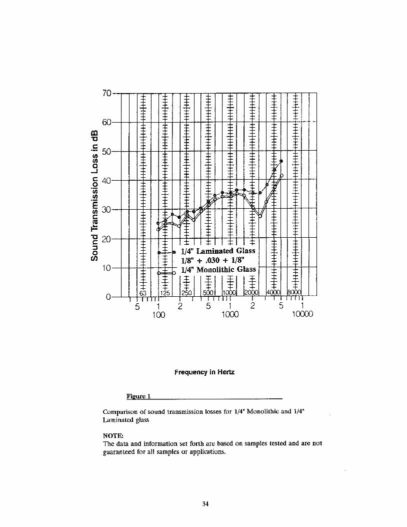
m "C
70
60
c:: 50 (/) (/)
o ..J
c:: 40 o 'iii .~
~ 30 t:: m F -g 20 ~ o
CJ)
10
o
-- --
-- ...,-
-I- -f-
-I- -f-
-- 41-:::::
~ ~
-- ~.: -~ :i;;;::
-- --63 125 TIl
5
Figure 1
1 100
-- -- -- -~
-:. -- -- --
-f- -r- -- -~
-f- - f-. - N ~
l~ f k
''q ~ ~ ~ IY ~
-,- -- -f-'{
It 1/4" Laminated Glass 1/8" + .030 + 1/8"
:) 1/4" Monolithic Glass
! ! ! ! 250
2
500 1000 2000 I I II I
512 1000
Frequency in Hertz
-- --
-- --;-
-V~ -~
J. p
rI ~ r V: ~ -~
f -~ -I-
-- - ~
-~ --4000 80 )()
I I T 5 1
10000
Comparison of sound transmission losses for 1/4" Monolithic and 1/4" Laminated glass
NOTE: The data and information set forth are based on samples tested and are not guaranteed for all samples or applications.
34
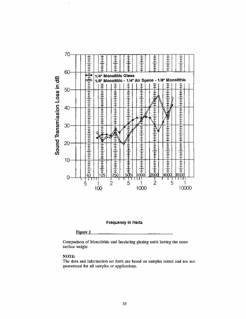
III '0 r:: en en 0 ..J C .2 en .~ E en c m F '0 c:::: ::J 0
(/)
70 I _I-
60 .:~ o:~
50
-~
40
-~
30
-~
20 -I-
10
-,.. 63 I I o
5
Figure 2
-- I- -- -- -- -I- -I- -I-
1/48 Monolthlc Glass 1/8" Monolthlc· 1/4" Air Space· 1/8" Monolithic
f--I-
-I-
f-
q .. ~ ~
-I-
-I-
125 I
1 100
-- -- -- ): r
-I- -- ..., , ~ --iT
~. ) \ ~ /
~ ~ ~ ~ 11 1
-- --=,
-- -- -~ -I-
-- -- -- -I-
250 5<JO 10 )() 2000 I I I I I I
2 5 1 2 1000
Frequency in Hertz
~ -~ ;> --
Ii
~ r --
V -- --
-I- -I-
-I- -I-
4000 ~() )() I I I
5 1 10000
Comparison of Monolithic and Insulating glazing units having the same surface weight
NOTE: The data and information set forth are based on samples tested and are not guaranteed for all samples or applications.
35

co "C
70
60
.5 50 en en o -' r: 40 o
'en en ·s 30 en c ca F "C 20 c :::l o
CI)
10
o
~ . Ix 1/4" laminated - 1/2" Air Space - 1/4" laminated ~ 1/4" Monolithic - 1/2" Air Space D 1/4· Monolithic P= F
le-t-: ~ 1/2" Monolithic
I- '~ i-I- -I- -I- -I- -I- -l- /- -I-
h
-I- -... -I- -- . -k:" .' . .:. ~ ~~I- - ... •• 1
r) [:} A . .:
~ If=' t.t::::
e1 W -I- -I- -I- ~tl ~ ~ l-
V ~ -f- - ...
lI-~ ~ ~ ~
<lJ. ~ 1· (-~ ~ I -I- 'N ~ IJ
~ -I- -I- -I- +- -I-
~ , i-I- -I- -I- - ... -f- -I- -I- -I-
1/S" glass - 0.30· - 1/S" glass -I- -l-
I 63 I 1125 1 1250 I 1 500 1 110001 120001 4000 00)(; I I I III
5 1 100
Figure 3
I I III IIII I
2 5 1 2 1000
Frequency in Hertz
I I I 5 1
10000
Comparison of Insulating glass with and without Laminated glass and equivalent weight Monolithic glass
NOTE: The data and information set forth are based on samples tested and are not guaranteed for all samples or applications.
36

~ 'C 0
r
f-I- I=" -f-
I- I=" -f-
f-I-
I=" ---
I-I- ' - Y -
I-I-- --
,-I- --
- I-- --63 1 5 I I I
5 1 100
Figure 4
f-
-f- -f- -t:"
f- f-
-~ -I- -I-
~ ~~ :... '" 1I
I-'-
-r -r -I-
lI-V
-r- -f- -I-
-I- -I- -I-
-- -f- -I-
--f- -- -I-
250 500 1000 I I II
2 5 1 1000
Frequency in Hertz
Sound transmission class contour
37
f-
-f- -f- -l-
-f- -f- -I-
-r- -r- -I-
-- -- --
-- -f- -I-
-- -'- -I-
-'- -I- -I-
2000 4000 80 )0 I T I I
2 5 1 10000

Figure 5
STC Test Results1
Test No.2 ConfigurationJ STCJ
TL-85-169 1/4" Monolithic 31
TL-85-198 1/2" Monolithic 36
TL-85-170 1/8" glass + 0.030" PVB + 1/8" glass 35
TL-85-224 1/8" glass + 0.060" PVB + 1/8" glass 35
TL-85-200 3/16" glass + 0.030" PVB + 3/16" glass 36
TL-85-229 1/4" glass + 0.030" PVB + 1/8" glass 36
TL-85-225 1/4" glass + 0.030" PVB + 1/4" glass 38
TL-85-228 1/4" glass + 0.060" PVB + 1/4" glass 39
TL-85-222 3/8" glass + 0.030" PVB + 1/4" glass 40
TL-85-230 1/2" glass + 0.060" PVB + 1/4" glass 41
Insulating
TL-85-212 1/8" glass + 1/4" Air + 1/8" glass, sealed 28
TL-85-294 1/4" glass + 1/2" Air + 1/4" glass, sealed 35
TL-85-293 1/4" glass + 1" Air + 1/4" glass, unsealed 37
Laminated Insulating
TL-85-189 1/8" + 0.030 + 1/8" + 3/8" Air + 3/16" glass, sealed 37
TL-85-238 1/8" + 0.030 + 1/8" + 1/2" Air + 3/16" glass, sealed 39
TL-85-235 1/8" + 0.030 + 1/8" + 1/2" Air + 1/4" glass, sealed 39
TL-85-192 1/8" + 0.030 + 1/4" + 1/2" Air + 1/4" glass, sealed 40
TL-85-196 1/4" + 0.030 + 1/4" + 2" Air- + 3/8" glass, unsealed 46
1. Tests sponsored by Monsanto Chemical Co. Units mounted in wood frames with wood stops and putty glazed.
2. Tests conducted at Riverbank Acoustical Laboratories. All tests conducted under ASTM E 90-83.
3. Results of similar tests may vary, influenced by size, type of framing, type of glazings and minor laboratory differences. The test size for these tests was 36" x 84". Many other configurations are possible.
'See page 3 for sealed units with 2" air space.
38

"!;:-~",:",,-fi-'r ~ ~" -j~ ~ ,,;--J"l[ ,,~" )~: _"'~: :~l ~-IH0)
'~" ;,~,~' 'XlII: S~EEm~ ~~~'ZllfSl~ ),fSI, ~~~~,fl(U'jl)(:HfU~> J&l~,m~ml~fSlS' , _ t: ~ """ ~ '" tc ~ \"" ~ Ji ,'" ~ ~ } -, _ ~ _ =~ ~ L" t ?:J _ ~,,! _ "- ~ :: >;t ,JOt; 'i "
SAFETY GlAZING IN HAZARDOUS LOCATIONS
ANSI Z97.1-1984, "Safety Performance and Methods of Test for Safety Glazing Material Used in Buildings," is the base on which most state and local safety glazing laws are built. It prescribes the safety requirements and test methods for tempered, laminated and wired glasses, and rigid plastics. Its primary purpose is to assure that glazing materials intended for hazardous locations will break safely when subjected to human impacts.
On July 6, 1977, the Consumer Product Safety Commission's "Safety Standard for Architectural Glazing Materials" 16 CFR 1201 became effective. This federal standard mandates the use of certified safety glazing materials in sliding patio doors, storm doors, interior and exterior doors, tub and shower doors, and enclosures. It includes test methods similar to, but in some ways more stringent than, those in ANSI Z97.1-1984. The federal safety standard supersedes (preempts) all non-identical safety glazing requirements of state laws and local building codes that address the same risk of injury as the federal law. Local building code groups are considering amendments that reference the test procedures of 16 CFR 1201 in lieu of ANSI Z97, at least for glazed panels. Local codes and laws should be thoroughly checked because they may contain some provisions applicable to glazed panels near doors, or to large panels near or between walkways that might be subject to human impact.
Willful violation of 16 CFR 1201 is considered a criminal offense under the federal Consumer Product Safety Act. Since 16 CFR 1201 may differ from safety glazing provisions in local codes and state laws, particularly in the specific areas of required usage, careful research is advisable to assure full compliance with the most stringent safety glazing requirements applicable.
In order to minimize the risk of liability, it may be prudent to install safety glazing materials in certain locations, such as those adjacent to areas with heavy pedestrian traffic or children activity, even though not required under federal, state or local safety standards and codes.
Replacement glazing of broken glass in locations which the laws or codes define as hazardous locations must be made with certified safety glazing material, even though the material previously in the opening was not such.
Safety glazing material must meet the above prescribed standards and appropriate building codes where applicable. Tempered glass that meets ASTM C 1048 is not automatically a safety glazing material. It must also meet ANSI Z97.1 and/or CPSC 16 CFR 1201.
The certifying agency is the Safety Glazing Certification Council (SGCC), a non-profit organization whose Board of Governors consists of five (5) industry members and five (5) general public members. The genera] membership consists of end producers of safety glazing products. Each member's product(s) must meet the prescribed testing and in-house inspection of their respective product(s) prior to their being labeled as a safety glazing product or products.
39

The design of a good glazing system incorporates experience and good judgement. Building movements relative to the framing system, method of erection, glass type and associated tolerances must be defined along with expected loads. The contribution to these by the glazing contractor, as well as the framing or wall contractor, should begin during the design and specification stage, and in any event no later than the shop drawing stage. Glass protection after installation is to be the responsibility of the general contractor.
A framing system should be designed adequately to retain the glass under the design load conditions, provide effective weather-tight sealing, prevent loads or pressure points on the glass resulting from building movement, prevent glass-to-metal contact, and minimize glass breakage from mechanical or thermal stresses.
It is important that the framing design be compatible with current glazing technology, thus avoiding possible construction delays or excessive erection and glazing labor costs. Some of the items in this section may seem to be only within the province of the framing supplier and erector and others only of the glazier, but frequently both functions are performed by a single entity. Even when they are performed by separate entities, complete cooperation is required to produce a satisfactory, weather-tight enclosure.
It is not possible in this manual to address specific details of every framing or glazing system. However, the following outline should be useful to those involved in any project as items for review with each other, with the responsible design professional and with the general contractor.
DESIGN REVIEW
A Nominal position of structural beam or floor slab at the point where anchors will attach. 1. Deflection under construction-applied loads, i.e., material stOCkpiling, equipment, material handling devices,
etc. 2. Deflection under live, wind and thermal loads and occupant-applied dead loads. This is especially important
where cantilevered floor slabs and structural materials subject to creep deflection are involved. B. Construction tolerances relating to the skeletal or support structure and mullion anchor points. C. Maximum building and/or glass framing movements at anchor points due to live load, dead load, creep
deflection, wind load and in-and-out twist. D. Movement of the building at isolation and expansion joints. E. Location and type of interior and exterior shading devices and their effect on the glass. See Figures 7 and 8,
pages 44 and 45. F. Location of heating and cooling outlets, blind or drapery pockets, and ventilation grilles that will affect air
temperature and movement on the glass. See Figure 8, page 45. G. Proposed location and type of fire safeing between floors. H. Location, type and thickness of spandrel glass insulation. J. Drip ledge at head of all glass to prevent glass staining from spandrel run-off. K Weather tightness, including flashings, primary and secondary seals, and weep systems.
SHOP DRAWING REVIEW
A Anchors and Expansion Joints: 1. Mullion vertical expansion joints should not apply loads on the glass due to movement of the structure or
the framing system. They should never be located such that they span the edge of an insulating glass unit. 2. Wind-load anchors must allow for free vertical expansion of the mullions without causing additional stress
on the mullion, mullion connectors or anchors. A dry, permanent lubricant is best for this purpose; oil or grease will lose their lubricating qualities over the long term.
3. Two-span mullions should have the dead-load anchor located as close as possible to their midpoint, thus equalizing upward and downward expansion and contraction. Three-span mullions should not be used.
4. Horizontal expansion joints should be no farther apart than 20 feet or every four lites of glass, whichever is less. Expansion should be from the center toward both ends.
B. Deflection of Framing: 1. Deflection of vertical mullions under design load should not exceed length of span + 175 or as defined by
applicable codes. When this deflection is considered excessive, it can be limited to a lesser amount. 2. Deflection of horizontal glass - carrying members should not exceed 1/8" nor should the deflection decrease
the head clearance of the panel below by more than 25%. 3. Twisting (rotation) of the horizontals due to the weight ofthe glass should not exceed 1°, measured between
ends and center of each span.
40
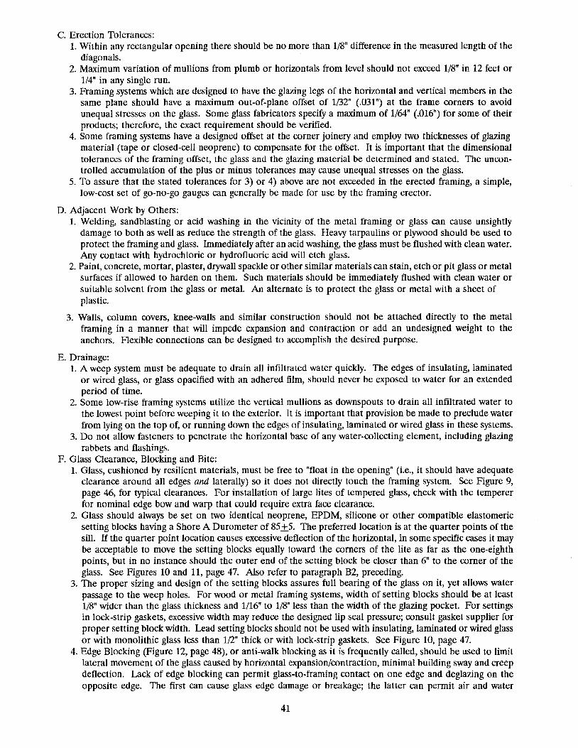
C. Erection Tolerances: 1. Within any rectangular opening there should be no more than 1/8" difference in the measured length of the
diagonals. 2. Maximum variation of mullions from plumb or horizontals from level should not exceed 1/S" in 12 feet or
1/4" in any single run. 3. Framing systems which are designed to have the glazing legs of the horizontal and vertical members in the
same plane should have a maximum out-of-plane offset of 1/32" (.031") at the frame corners to avoid unequal stresses on the glass. Some glass fabricators specity a maximum of 1/64" (.016") for some of their products; therefore, the exact requirement should be verified.
4. Some framing systems have a designed offset at the corner joinery and employ two thicknesses of glazing material (tape or closed-cell neoprene) to compensate for the offset. It is important that the dimensional tolerances of the framing offset, the glass and the glazing material be determined and stated. The uncontrolled accumulation of the plus or minus tolerances may cause unequal stresses on the glass.
5. To assure that the stated tolerances for 3) or 4) above are not exceeded in the erected framing, a simple, low-cost set of go-no-go gauges can generally be made for use by the framing erector.
D. Adjacent Work by Others: 1. Welding, sandblasting or acid washing in the viCinity of the metal framing or glass can cause unsightly
damage to both as well as reduce the strength of the glass. Heavy tarpaulins or plywood should be used to protect the framing and glass. Immediately after an acid washing, the glass must be flushed with clean water. Any contact with hydrochloric or hydroflUOric acid will etch glass.
2. Paint, concrete, mortar, plaster, drywall spackle or other similar materials can stain, etch or pit glass or metal surfaces if allowed to harden on them. Such materials should be immediately flushed with clean water or suitable solvent from the glass or metal. An alternate is to protect the glass or metal with a sheet of plastic.
3. Walls, column covers, knee-walls and similar construction should not be attached directly to the metal framing in a manner that will impede expansion and contraction or add an undesigned weight to the anchors. Flexible connections can be designed to accomplish the desired purpose.
E. Drainage: 1. A weep system must be adequate to drain all infiltrated water quickly. The edges of insulating, laminated
or wired glass, or glass opacified with an adhered film, should never be exposed to water for an extended period of time.
2. Some low-rise framing systems utilize the vertical mullions as downspouts to drain all infiltrated water to the lowest point before weeping it to the exterior. It is important that provision be made to preclude water from lying on the top of, or running down the edges of insulating, laminated or wired glass in these systems.
3. Do not allow fasteners to penetrate the horizontal base of any water-COllecting element, including glazing rabbets and flashings.
F. Glass Clearance, Blocking and Bite: 1. Glass, cushioned by resilient materials, must be free to "float in the opening" (i.e., it should have adequate
clearance around all edges and laterally) so it does not directly touch the framing system. See Figure 9, page 46, for typical clearances. For installation of large lites of tempered glass, check with the temperer for nominal edge bow and warp that could require extra face clearance.
2. Glass should always be set on two identical neoprene, EPDM, silicone or other compatible elastomeric setting blocks having a Shore A Durometer of 85+5. The preferred location is at the quarter points of the sill. If the quarter point location causes excessive deflection of the horizontal, in some specific cases it may be acceptable to move the setting blocks equally toward the comers of the lite as far as the one-eighth points, but in no instance should the outer end of the setting block be closer than 6" to the corner of the glass. See Figures 10 and 11, page 47. Also refer to paragraph B2, preceding.
3. The proper sizing and design of the setting blocks assures full bearing of the glass on it, yet allows water passage to the weep holes. For wood or metal framing systems, width of setting blocks should be at least 1/8" wider than the glass thickness and 1/16" to 1/8" less than the width of the glazing pocket. For settings in lOCk-strip gaskets, excessive width may reduce the designed lip seal pressure; consult gasket supplier for proper setting block width. Lead setting blocks should not be used with insulating, laminated or wired glass or with monolithic glass less than 1/2" thick or with lock-strip gaskets. See Figure 10, page 47.
4. Edge Blocking (Figure 12, page 48), or anti-walk blocking as it is frequently called, should be used to limit lateral movement of the glass caused by horizontal expansion/contraction, minimal building sway and creep deflection. Lack of edge blOCking can permit glass-to-framing contact on one edge and deglazing on the opposite edge. The first can cause glass edge damage or breakage; the latter can permit air and water
41

infiltration as well as changing the glazing design from four-sided to three-sided support. Top blocking is recommended only for narrow, tall lites where the greatest thermal movement is vertical.
5. Design to accommodate substantial building sway and/or seismic movement are separate considerations not related to side-walking. The glass must be free to move within the glazing rabbet without touching the framing while, at the same time, maintaining adequate bite under the most adverse design conditions. The anticipated sway or seismic movement within the framing dimensions must be stated to properly design the height of the glazing legs and the bite of the glass. Obviously, bite will be greater than that shown in Figure 9, page 46; to properly anticipate high thermal-edge stresses from excessive bite, the glass should be heat treated. The web of the framing should be cushioned at all four corners to prevent glass-to-framing contact, yet allow the necessary clear space for the anticipated movement. To summarize, the allowance for movement, bite and cushioning will substantially increase edge clearance (B) and bite (C), Figure 9, page 46 and provision for cushioning will resemble edge blocking (A) at sill corners and (D) at top corners, with clearance much greater than all, Figure 12, page 48.
6. Figures 13, 14 and 15, page 49, cover the special conditions required for doors, casement, and vertically pivoted and horizontally pivoted windows. Some insulating glass fabricators may modify or void their warranty when insulating glass is "cross-blocked" as in Figure 14, page 49.
GLAZING OPERATIONS A Glazing Preparation:
1. SpecifiC glazing recommendations of the glass manufacturer and the glazing material manufacturer(s) should be sought, discussed and agreed on before glazing begins.
2. The chemical and physical compatibility of all glazing materials and framing sealants with each other and with like materials used in glass fabrication must be established.
B. Glass /Receiving: 1. Plan glass shipping schedule to minimize job site storage time and to avoid off-job site storage and
rehandling. 2. Reduce handling by scheduling shipments by floors and by initially locating crated products as close to their
installation areas as possible. 3. Note on the freight bill or delivery receipt any evidence of shortage, abuse, damage or wet packaging and
have delivering driver sign. Set the questionable crates aside in a readily accessible space and request, in writing, an immediate inspection by the carrier's representative. Inspect glass from a few undamaged crates to be certain there is no concealed damage and that the product is acceptable.
4. Inventory received merchandise immediately, notify supplier of any shortages, and report any concealed damage to the carrier, requesting in writing an immediate inspection of the paCkages or crates.
C. Glass Storage: 1. Store crated glass in a cool, dry, shady well-ventilated area where it will not be subject to rain or direct sun. 2. Obtain a statement from the project structural engineer as to the maximum total weight of crates that can
be stored at each proposed location. 3. If not opened immediately, cover cases with waterproof plastic or canvas. Air circulation is needed under,
across the top, around the sides and between the crates to minimize potential condensation within the crates.
4. Secure crates to building columns if possible; otherwise, stand several cases together and fasten them to each other with scrap lumber, to prevent heavy winds from overturning them. Crates should be placed 2" to 6" off the floor and tilted 1" per foot of height to expedite unpacking. Also see 3) above.
D. Job Conditions: 1. Advise the general contractor of the protective steps that must be taken by other trades in conjunction with
any subsequent adjacent work. See Shop Drawing Review, Dl, D2 and D3, page 41. 2. Inspect the work of the framing erector for compliance with plans, specifications and shop drawings.
Check as follows: a. Framing is within tolerance for plumb and level and is in plane. b. Each opening is within tolerance for size and squareness. c. Offsets at framing corners are within specified tolerance. d. The glazing rabbet is free of debris and obstructions. e. The weep system is open. f. The glazing surfaces are free of moisture, dirt, grease, oil or any deleterious material. g. Screws, bolts, rivets or weld fillets do not reduce the minimum required face or edge clearance. See
Figure 9, page 46. h. All joinery, connectors, screw or bolt heads, rivets and water dams are effectively sealed.
42
i. All steel or wood glazing rabbets and contacts of dissimilar metal are painted. E. Installation of Glass:
1. Temperature conditions during glazing must be within the limits required by the glazing material manufacturer.
2. Measure glass for proper dimensions, recognizing manufacturer's published tolerances. 3. Always use a rolling block to rotate glass. See Figure 17, page 51. 4. Do not impact the glass against the framing during installation. This can cause edge damage. Pocket, or
"Flush Glazing", is particularly susceptible to glass edge damage from impacting the frame and requires preCise sizing of the glass and extra care during installation.
5. Always use suction cups to shift a lite of glass within the opening. Raising or drifting the glass with a pry bar can cause edge damage.
6. Set aside all lites with spalls or rough edge chips for judgment by others as to usability. See Figure 16, page 50.
7. Glass with flares or bevels at the bottom in the vicinity of the setting blocks should be rotated 1800 to place these at the top.
8. Remove all labels immediately from the faces of the glass. F. Post Glazing:
1. Identify glazed areas by hanging narrow streamers from the framing. Do not mark directly on, or fasten identification to, the glass.
2. Advise general contractor to clean installed glass frequently during construction. Construction dust, leachate from concrete and rusting from steel can combine with dewar condensation to form mild chemicals which may etch or stain glass.
3. Advise general contractor not to store or place other materials in contact with the glass. 4. Advise general contractor not to permit materials to be stored adjacent to the glass in such a manner that
a heat trap is created which could cause glass breakage. 5. Advise general contractor to protect the glass from other trades. See "Shop Drawing Review," Dl, D2 and
D3, page 41.
43

FIGURE 7
Outdoor Shading Patterns (Adapted from PPG-TSR 130)
Preferable for Tinted or Coated Glasses
75% ~ SHADEDU
.~ •..
25% 0 SHADED •
!1
U o Acceptable for Clear Glasses
Marginal for Tinted or Coated Glasses
:1:1 .............................
25% D·· .....•............. · .. SHADED! [] Marginal for Clear Glasses'
Unfavorable for Tinted or Coated Glasses' . [J. :-: .-:';'
•.•..•...•..•..•.....•.•••....•..•.•.•..•...••••..•...•.•.. : ..••........••. : .••..
.... [J ...... .
.:!.·.···.·.·.ii .•.••. i .. ...•.
25% [J SHADED.; •.• ,[J ...... <.
:,:::,:::,:::':.:.=: .. D·.· .... · .. ··· ..... ·
. .
1. Investigate Heat Strengthening or Tempering. 2. Heat Strengthening or Tempering probably Required.
44

FIGURE 8 Indoor shading & Heat Duct Locations
Glass and Shading Device Clearances
Draperies, venetian blinds or other interior shading devices must be hung so as to provide space at the top and bottom or one side and bottom to permit natural air movement over the room side of the glass. The following criteria must be met to avoid formation of a heat trap:
1. Minimum 1-1/2" clearance required top and bottom or one side and bottom between shading device and surrounding construction.
2. Minimum 2" clearance between glass and shading device. 3. Heating/cooling outlets must be to room side of shading
device. Heat strengthening or tempering of the glass may be
necessary for some installations to offset the effects of glass size, solar absorption, exterior shading, interior shading, climatic conditions, lack of proper clearances noted above or improper placement or directing of air flow.
45

IIIIII1 IIIIII __ ~ ____ -,CL-_1_/_16" Watershed
c
B
t
FIGURE 9 TYPICAL FACE & EDGE CLEARANCE & BITE
Thickness inches
S.S. 1/8 - D.S.1 1/8 - D.S.2
3/161
3/162
1/4 5/16 3/8 1/2 5/8 3/4 7/8
1/2 5/8 3/4 1
1/4
1Annealed Glass only ~empered Glass only
mm
2.5 3 3 5 5 6 8 10 12 15 19 22
12 15 19 25
6
Minimum Clearance A=Face B=Edee C=Bite
Monolithic Glass 1/16 1/8 1/4 1/8 1/8 1/4 1/8 1/4 3/8 1/8 3/16 5/16 1/8 1/4 3/8 1/8 1/4 3/8 3/16 5/16 7/16 3/16 5/16 7/16 1/4 3/8 7/16 1/4 3/8 1/2 1/4 1/2 5/8 1/4 1/2 3/4
Insulatin2 Glass 1/8 1/8 1/2 1/8 1/8 1/2
3/16 1/4 1/2 3/16 1/4 1/2
Ceramic Coated Spandrel Glass 3/16 1/4 1/2
NOTE: Typical clearances above may vary by manufacturer, particularly for some special products or applications. Follow the recommendations of the glass manufacturer, fabricator or sealant supplier for individual instances.
46

FIGURE 10 - SETIING BLOCK LOCATION (PREFERRED)
W/4 W/4
W
47
85 ± 5 Shore a Durometer Blocks centered at 1/4 points with length' dependent on glass area.
*SE'ITING BLOCK LENGTH PER BLOCK 1. Neoprene* = 0.1" per Sq. Ft. Glass Area 2. Lead = 0.05" per Sq. Ft. Glass Area 3. Lock-strip Gasket = 0.5" per Sq. Ft. Glass Area 4. Never Less than 4" for 1 & 2. 5. Never Less than 6" for 3.
NOTE: Lead blocks should NEVER be used with laminated, insulating or wired glass, or in structural gaskets, nor should they be used with glass less than 1/2" thick.
*See F2, this chapter.
FIGURE 11-ALTERNATE SETIING BLOCK LOCATIONS
(Generally Acceptable"')
r W
8S± S Shore a Durometer Blocks positioned with end of block within W/8 or 6" of glass edge, whichever is greater. Block length determined as on Fig. 10.
X= W/8 OR 6", WHICHEVER IS GREATER • Check with glass manufacturer or fabricator

FIGURE 12 - EDGE BLOCKING
LOCATION A LOCATION B
CONSULT MANUFACTURER FOR PREFERRED LOCATION
BLOCKS MUST BE:
1. Hardness per manufacturer, usually 60-70 Shore A
2. A Minimum of 4" long 3. Placed in the Vertical Channel 4. Sized to allow a nominal
1/8" Clearance between the edge of the glass and the block
48
LOCATION C
LOCATION D
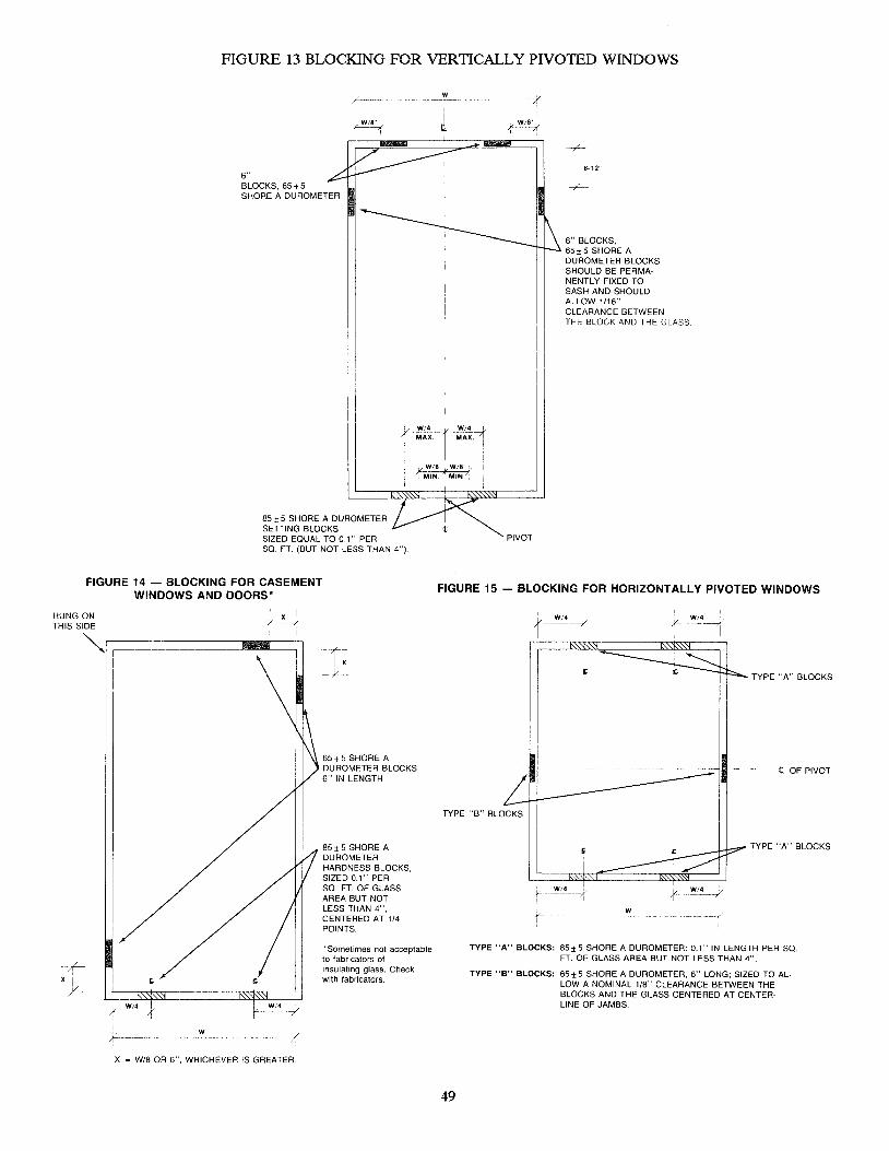
FIGURE 13 BLOCKING FOR VERTICALLY PIVOTED WINDOWS
6" BLOCKS, 65 + 5 SHORE A DUROMETER
85 ± 5 SHORE A DUROMETER SETIING BLOCKS SIZED EOUAL TO 0.1" PER SO. FT. (BUT NOT LESS THAN 4").
FIGURE 14 - BLOCKING FOR CASEMENT WINDOWS AND DOORS'
HUNG ON I. x j THIS SIDE r 1
~r--;:::=========-~
W/4 /-
W
x = W/8 OR 6", WHICHEVER IS GREATER
65±5 SHORE A DUROMETER BLOCKS 6" IN LENGTH
85±5 SHORE A DUROMETER HARDNESS BLOCKS, SIZED 0.1" PER SO. FT. OF GLASS AREA BUT NOT LESS THAN 4", CENTERED AT 114 POINTS.
* Sometimes not acceptable to fabricators of insulating glass. Check with fabricators.
w
{ W/8~
PIVOT
-r---8-12"
6" BLOCKS, 65±5 SHORE A DUROMETER BLOCKS SHOULD BE PERMANENTL Y FIXED TO SASH AND SHOULD ALLOW 1/16" CLEARANCE BETWEEN THE BLOCK AND THE GLASS
FIGURE 15 - BLOCKING FOR HORIZONTALLY PIVOTED WINDOWS
~_ W/4
TYPE "A" BLOCKS
.. --t, OF PIVOT
TYPE "B" BLOCKS
49
TYPE "A" BLOCKS
;c- W
TYPE "A" BLOCKS: 85±5 SHORE A DUROMETER: 0.1" IN LENGTH PER SO FT. OF GLASS AREA BUT NOT LESS THAN 4".
TYPE "B" BLOCKS: 65±5 SHORE A DUROMETER, 6" LONG; SIZED TO ALLOW A NOMINAL 1/8" CLEARANCE BETWEEN THE BLOCKS AND THE GLASS CENTERED AT CENTERLINE OF JAMBS

FIGURE 16 EDGE CHARACTERISTICS
CONVOLUTIONS -Smooth Rolling Surfaces on edge of glass. Not a weakening factor.
RUN LINES - smooth, rolling lines on edge of glass. Not a weakening factor.
SHARK TEETH -Dagger-like imperfections which start from scored surface. Breakage possibility increases as depth, roughness, and number of shark teeth increase.
SERRATION HACKLE -Edge imperfections, usually perpendicular to glass surface, which score. Breakage possibility increases as density and depth increase.
FLARE - Sharp protrusion at junction of edge and glass surface. Susceptible to damage. Not a weakening factor.
BEVEL - Edge that is not not perpendicular to surfaces. Not a weakening factor.
FLAKE CHIPS -Smooth shallow chips. Not a weakening factor.
ROUGH CHIPS -Rough penetrating chips.
FROST/RUBBLE -Fine grain effect on glass edge. Not a weakening occur at surface opposite factor.
Courtesy PPG Industries. From TSR 130
50

ROLLING BLOCK
MATERIALS REQUIRED 1 pc. 1/2" Plywood
12" x 12", cut
FIGURE 17
diagonally in half - ___ ~ 2 pc. 2" x 2" x 6"
Nails
I I I
I 1
1 I I
I 1 I
\
1 1 ..1---_-), , __ -r I _- , ~-T -r
I I I
I / /
/ I 3" RADIUS
~ ..,--:::: :::0-,/ ;' /.- - / /
/ '/ /' ,
1 / /,
1,.... ............ / I ..-""
__ -..J.----;""""--_-'..~ - ~ -- ---- -- ----::---..- .--
~~~--~" 1/2" 1 1/2" 1/2"
51

" ' " ", ". :I~. SeEllii:lFiI C!l ~I!JJl!le~1 N~S ~el!l G bfl«ZI rile "," !J ~ A -< ~ .. "" '"" ~ ~ 1 ~ "i "f -
COMPATIBILITY
The assurance of compatibility of sealants cannot be overemphasized. Every glass installation involves at least two sealants and frequently several more. These sealants include the following:
a. Sash joinery sealant b. Exterior glazing sealant (weather seal) c. Interior glazing sealant d. Heel or toe bead e. Insulating glass sealant f. Butyrallaminate in laminated glass g. Structural silicone sealant
The proven compatibility of all materials involved is essential to the long-term success of any glazing installation. This is of extreme importance with structural silicone glazing.
Chemical reaction from physical contact of incompatible materials can (and does) occur. Less frequently, volatile constituents given off by one material can adversely affect another within the closed confines of the glazing rabbet. Sealant manufacturers generally are willing to conduct compatibility tests in their laboratories and to give the results in writing.
Compatibility should always be investigated, never assumed. ASTM C 510, C 794, C 864 and C 1087 procedures are a good starting point for guidance.
GLASS SETrING
Uneven or point pressures on glass can result from improper positioning of the glass on the setting blocks. Most glazing systems in common use today involve placing a wet sealant under constant pressure or a dry sealant under compression.
When the glass is set, sufficient pressure must be placed against the glass, as it is lowered onto the setting blocks to properly place the sealant under pressure or compression. This should properly position the glass on the setting blocks. The pressure-producing glazing material should immediately be inserted to maintain the pressure.
This can be typified by the example of a wet/dry glazing method having shimmed tape for the weather seal and a hard rubber wedge as the pressure-producing member. The glass should be pushed firmly against the tape across the sill while held with cups, up off the setting blocks about 1/32"; the wedge should then be inserted the full width of the sill before the glass is allowed to settle onto the setting blocks. If this procedure is not practical, ease the glass onto the setting blocks while firmly pushing outward against the tape, insert the wedge the full width of the sill, then lift the glass off the setting block about 1/16" and ease it down again. Short, temporary pieces of wedge material should be used with caution when the fit of all components is extremely tight; excessive point pressure can readily cause glass breakage. If the proper pressure is not achieved initially, or is not maintained, the result can be an insufficient weather seal and/or point pressure on the glass at the setting blocks.
WET GlAZING
GENERAL Wet glazing materials can be classified into three general types: 1. Preformed Tape 2. Gunable Elastomeric Sealants
a. Non-curing b. Curing
3. Putty and Glazing Compounds Lateral shims are normally required with wet glazing materials to center the glass in the opening and to hold
the glass in position when subjected to wind load, vibration or building movement. A typical wet glazing installation is shown in Figure 18, page 54.
PREFORMED TAPE Preformed tape is generally an elastomeric rubber material extruded into a ribbon of a width and thickness
suitable for a specific application. The tape remains resilient over a long time period and has excellent adhesion
52
to glass, metal or wood when continuous pressure is applied. Tape incorporating an integral, continuous shim is available and desirable. Elastic hybrid tapes, without an integral shim, are now available for many applications of compression glazing. These tapes should not be confused with the typical, non-elastic tapes that have long been available without an integral shim.
The tape comes as a roll with a release paper on one side. It should be applied to a properly prepared, clean, dry surface not more than 24 hours prior to glazing. Glazing surfaces should be prepared in accordance with the manufacturer's instructions to assure good adhesion. The release paper should not be removed until the glass is ready to be installed. All joints and corners should be squared and tightly, neatly butted; they must NOT be overlapped. Do not stretch the tape to make it fit. Joints should be lightly daubed with a compatible gunable sealant to assure a positive seal. The only joints in the tape should be at the corners.
GUNABLE ELASTOMERIC SEALANTS Non-curing gunable sealants are usually used as a metal-to-metal joint sealant in non-exposed locations. If of
the non-skinning type, the always-tacky surface can quickly collect dirt and become unsightly if used in an exposed location.
Curing-type gunable sealants are materials such as the polysulfides, silicones, urethanes and acryliCS. They cure to a resilient solid state by chemical reaction with external forces such as temperature and humidity, or by solvent release. They should be used as a gunned-in-place glazing sealant or as a cap bead. Surfaces must be clean, dry and, if necessary, primed in accordance with the manufacturer's instructions. Ambient temperatures must be within the manufacturer's specified range during time of application and cure. Shims, preferably continuous, must be used in accordance with the recommendations of the glass manufacturer.
PUTTY AND GLAZING COMPOUNDS Putty or glazing compounds have largely fallen into disuse because of a lack of service effectiveness in medium
to-large lite glazing. The oil and solvent content make putty and glazing compounds incompatible with neoprene, butyls, polysulfides, silicones, EPDM and acrylics. Putty or glazing compound sh.ould NEVER be used to glaze laminated or insulating glass.
LATERAL SHIMS
Lateral shims, as noted earlier, center the glass laterally within the glazing rabbet. They control face clearance, dimension A, Figure 9, page 46. Also see the typical use of lateral shims in Figure 18, page 54.
Intermittent shims should be spaced uniformly at 18" to 24" centers. Positioning should start at the setting blocks and proceed equally, both left and right, so shims on opposite jambs are opposite each other. If the glazing system is wet glaze both inside and outside, the inside and outside shims should be exactly the same dimensions and exactly opposite each other. Improper placement can create pressure points on the glass.
Continuous shims are preferable in that they provide a uniform cushion around the perimeter of the glass and save the labor of separately and properly pOSitioning individual shims. Preformed tape with an integral continuous shim has proven to be highly acceptable in tape glazed systems. Elastic hybrid tapes, which do not require an integral shim, are also highly acceptable for compression glazing; they are not to be confused with non-elastic, unshimmed tapes.
The desired hardness range of shims varies according to the desires of various glass manufacturers. Typically, 40 to 60 Shore A Hardness is recommended, but the glass manufacturer should be consulted for their recommendations for specific projects.
DRY GlAZING
Dry glazing is the common designation for systems utilizing extruded rubber gaskets as one or both of the glazing seals. Their popularity has grown in recent years because installation weather, workmanship and compatibility are usually of less importance to proper functioning than for wet glazing systems.
There are two major types of engineered dry glazing systems, compression gaskets and lOCk-strip gaskets. Lockstrip gaskets are covered as a separate category later in this chapter.
Compression gasket glazing systems usually employ a soft, closed-cell gasket on one side of the glass and a firm, dense gasket (usually called a wedge) on the other side. The gaskets are generally of neoprene, EPDM or silicone rubber composition. By careful sizing of the gaskets, with proper consideration given to the plus/minus tolerances of glass, metal and rubber, the softer member will compress 25% to 40% and form a weather seal when the dense gasket is in place. (Check for probable bow, warp and kink tolerances of heat-treated glass which may affect the amount and uniformity of compression.)
53

FIGURE 18 Typical Wet & Dry Glazing Systems
WET/DRY
Cap Bead (optional)
"" Pre-shimmed Tape ------l!I-;
·Weep
Nail or Staple
@Anglel
Compatible Air Seal
INSULATING GLASS IN WOOD SASH PREFERRED INSTALLATION
1. Tape or Gunnable Sealant 2. Setting Block 3. Weep* 4. Continuous Shim
Neoprene Gasket
DRY
.Weep----------~~~========~~
WET
Pre-shimmed Tape Cap Bead
r----.L.L Continuous Li;:.c;/y~~ Spacer shim
Heel Bead (Air Seal)
*Note: At least 2-3/8" diameter weeps per lite with access unimpeded by setting blocks. Positions can vary, as shown.
54

Typical Compression Gaskets
Soft, Closed-cell Gaskets
A B c
Firm, Dense Gaskets
o E F
The corners ofthe soft gasket are frequently molded or vulcanized, thus forming a continuous, joint-free glazing material around all sides of the glazing rabbet. A weep system is essential with any compression gasket glazing system (see Figure 18, page 54).
Gaskets should always be fabricated or cut slightly longer than the opening they are to fit. The gasket manufacturer will always have a recommendation in this regard.
Installation of the soft gasket should begin from two adjacent corners of the opening and two or three inches of gasket should be pressed into place at each corner. Two or three inches of the gasket at its center should be pressed into place at the midpoint between corners. If the opening dimension is large, repeat the process at the quarter points. Then insert the balance of the gasket, working from two already inserted points toward each other. This procedure will distribute the excess of the gasket equally and will forestall any tendency to stretch the gasket. If the glass is not positioned properly on the setting blocks, starting installation of the wedge at the corners, as most gasket manufacturers recommend, can cause severe bending stress on the glass. This can cause immediate or later glass breakage. See the suggested procedure under Glass Setting, page 52.
A typical compression gasket glazing system is shown in Figure 18, page 54. Typical compression gaskets are shown in Figure 19, above.
WET/DRY GlAZING
Wet/dry glazing is simply a combination of wet glazing and dry glazing design. A typical wet/dry glazing system is shown in Figure 18, page 54.
55
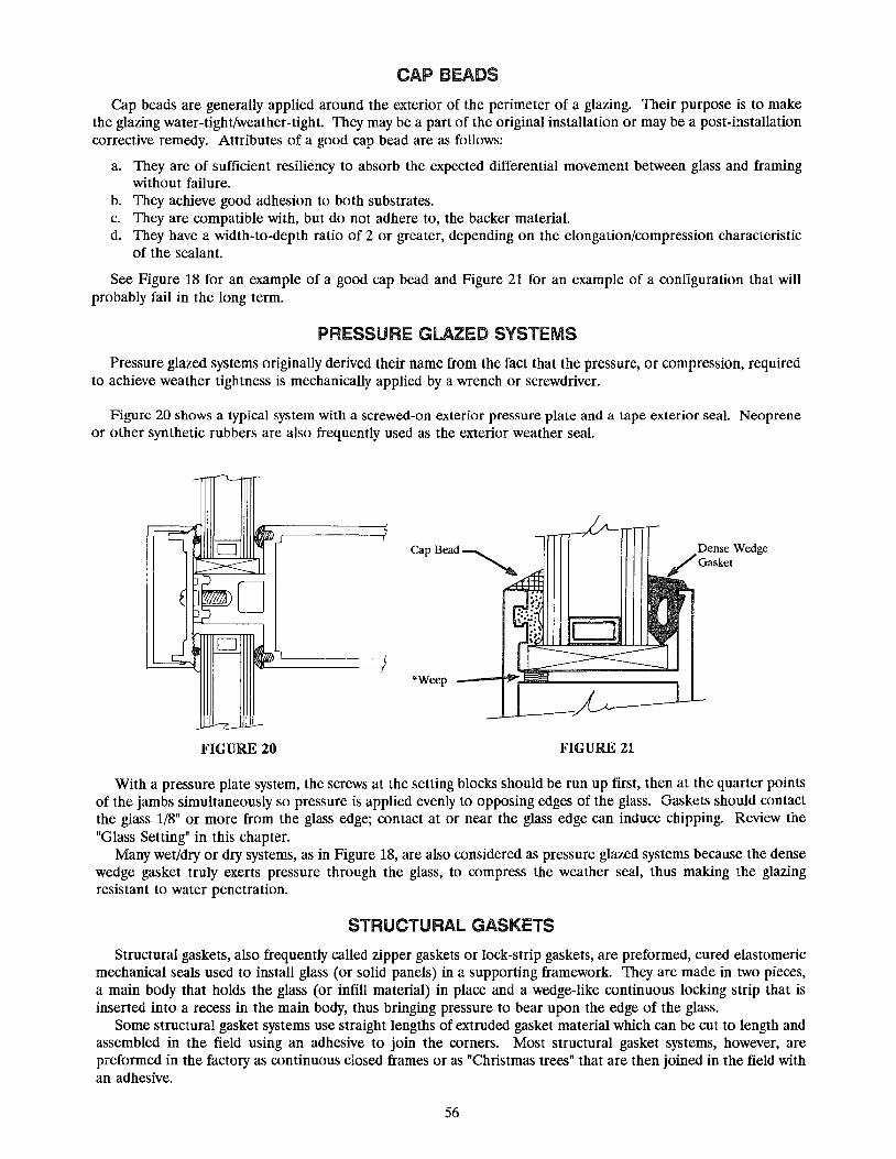
CAP BEADS
Cap beads are generally applied around the exterior of the perimeter of a glazing. Their purpose is to make the glazing water-tight/weather-tight. They may be a part of the original installation or may be a post-installation corrective remedy. Attributes of a good cap bead are as follows:
a. They are of sufficient resiliency to absorb the expected differential movement between glass and framing without failure.
b. They achieve good adhesion to both substrates. c. They are compatible with, but do not adhere to, the backer material. d. They have a width-to-depth ratio of 2 or greater, depending on the elongation/compression characteristic
of the sealant.
See Figure 18 for an example of a good cap bead and Figure 21 for an example of a configuration that will probably fail in the long term.
PRESSURE GlAZED SYSTEMS
Pressure glazed systems originally derived their name from the fact that the pressure, or compression, required to achieve weather tightness is mechanically applied by a wrench or screwdriver.
Figure 20 shows a typical system with a screwed-on exterior pressure plate and a tape exterior seal. Neoprene or other synthetic rubbers are also frequently used as the exterior weather seal.
·Weep
FIGURE 20 FIGURE 21
Dense Wedge Gasket
With a pressure plate system, the screws at the setting blocks should be run up first, then at the quarter points of the jambs simultaneously so pressure is applied evenly to opposing edges of the glass. Gaskets should contact the glass 1/8" or more from the glass edge; contact at or near the glass edge can induce chipping. Review the "Glass Setting" in this chapter.
Many wet/dry or dry systems, as in Figure 18, are also considered as pressure glazed systems because the dense wedge gasket truly exerts pressure through the glass, to compress the weather seal, thus making the glazing resistant to water penetration.
STRUCTURAL GASKETS
Structural gaskets, also frequently called zipper gaskets or lock-strip gaskets, are preformed, cured elastomeric mechanical seals used to install glass (or solid panels) in a supporting framework. They are made in two pieces, a main body that holds the glass (or infill material) in place and a wedge-like continuous locking strip that is inserted into a recess in the main body, thus bringing pressure to bear upon the edge of the glass.
Some structural gasket systems use straight lengths of extruded gasket material which can be cut to length and assembled in the field using an adhesive to join the corners. Most structural gasket systems, however, are preformed in the factory as continuous closed frames or as "Christmas trees" that are then joined in the field with an adhesive.
56

The gasket should be made at least 1% larger than the opening into which it is to be installed so it is under slight linear compression.
The frame onto which the gasket is installed should be clean, smooth and free of imperfections. Corner offsets of the frame should not exceed 1/64" (.016"). All frame joinery must be sealed.
Setting blocks, or setting strips as the structural gasket industry prefers to call them, have the major task of distributing the weight of the glass to avoid deforming the gasket, which could decrease lip pressure. They are therefore considerable longer than for the usual glass settings in metal or wood. See Figure 10, page 47.
Glass size, as well as opening size, is more critical than settings in metal or wood. Lip pressure and bite are extremely important in achieving weather tightness. Close attention must be given to tolerances of framing, gasket and glass to achieve a weather-tight installation.
Most laminated and insulating glass fabricators require a supplemental exterior wet seal as a warranty condition for structural gasket installations, as well as a weep system. While the published literature of gasket manufacturers or glass producers does not specifically call for a supplemental wet seal or a weep system in conjunction with monolithic glass, prudence indicates both are desirable in the possible prevention of water penetration into a building and hence should be specified.
Figures 22 and 23, below, show typical sill conditions for monolithic and insulating glass installations. A considerable amount of technical literature exists regarding structural gasket usage, in addition to manufacturers' literature, as a guide for successful installations. Some of this literature includes the following:
"LoCk-Strip Gaskets in Architectural Applications," Aluminum Curtain Walls, Volume #4, December, 1971, American Architectural Manufacturers Association (AAMA).
ASTM STP 552, C. J. Parise, "Window and Wall Testing," pp. 44-46, American Society for Testing and Materials, 1974.
ASTM STP 606, J. A Dallen and P. Paulus, "Lock-Strip Glazing Gaskets," pp. 223-266, American Society for Testing and Materials, 1976.
ASTM C 542, "Standard Specification for Lock-Strip Gaskets"; and ASTM C 716, "Standard Recommended Practice for Use of Lock-Strip Gaskets," American Society for Testing and Materials.
Secondary Seal (Optional)
FIGURE 22 TYPICAL SILL DETAIL MONOLITHIC GLASS
-Weep (Optional)
EXTERIOR
BUTT -JOINT GlAZING
Optional Weep location
~--~--+---'Weep
FIGURE 23 TYPICAL SILL DETAIL INSULATING GLASS
(Required)
EXTERIOR
Butt-Joint Glazing is a method of installing glass to provide wide horizontal areas of vision without the interruption of vertical framing members. It utilizes a generally conventional approach to the head and sill glazing, using metal or wood retaining members with wet, dry or wet/dry sealants. However, the vertical glass edges are spaced slightly apart and sealed, generally with a silicone sealant. The sealant serves only as a weather stop at the vertical joints; therefore, this vertical glass and sealant joint cannot be considered to be structural.
57

The design and execution of a satisfactory butt-joint glazing installation requires more attention to detail at every stage than does a conventional system with vertical framing members. The glass is supported on only two edges; the usual design load charts for four-edge support are not valid. Deflection and glass stressing under design load is substantially greater than with four edges supported and must be investigated.
Glass that is only supported on two edges will bend like a beam under wind load, whereas when supported on four edges it bends like a diaphragm or trampoline. Not only are the bending characteristics different, but also are the wind load abilities. For example, one-quarter inch glass 48" high, when supported only at head and sill, will deflect 1.0" under a 20 psf wind load regardless of the length of its two supporting edges; on the other hand, a one-quarter inch glass 48" x 120", when supported on all four sides, will have a center deflection of 3/4" regardless of which dimension is vertical, when subjected to a 30 psf wind load.
Tempering will not reduce glass deflection (see Chapter II, Tempered Glass). The inherent warp of tempered glass can complicate the achievement of a neat vertical silicone joint.
Precise leveling of the sill member is necessary and provision must be made at the head for deflection of the structure. The vertical joints should be ground with a slight kerf and should be polished for best esthetics.
Insulating glass is not suitable for butt-joint glazing. When the glass deflects, the sealants are placed in extreme shear along the unsupported edge, between the glass and spacer. Early seal failure is virtually assured. Additionally, the spacer, generally of thin, roll-formed aluminum, has very little structural strength to aid in resisting the deflection bending. An exception to this is mentioned in Chapter II under Insulating Glass.
Wet grinding of the vertical edges is usually recommended for best appearance. Most building codes do not provide specifically for the use of twa-edge glass support systems. It is the respon
sibility of the design professional to call to the attention of code officials the use of two-edge supported glass and to secure the necessary approvalS. A typical butt-jOint is shown in Figure 24.
Glass Joint Width
Thickness Min. Max.
3/8" 3/8" 7/16"
1/2" 3/8" 7/16"
5/8" 3/8" 1/2"
3/4" 3/8" 1/2"
7/8" 3/8" 1/2"
TABLE 14 RECOMMENDED JOINT WIDTHS
FOR BUTT-JOINT GLAZING
GLASS
\ ~sealant
~
.I '" t= Joint Width
Figure 24 BUTT-JOINT GLAZING
Glass and sealant manufacturers recommendations for edge treatment and edge quality of the glass, specific sealant, use of primers, and construction (sealing) of the butt-joint must be followed exactly. Recommended joint widths are listed in Table 14.
Butt-joint glazing should not be confused with structural silicone glazing. Both have the same exterior appearance, but structural silicone glazing has an interior vertical mullion to which the glass is adhered with a sealant.
STRUCTURAL SILICONE GlAZING
Structural sealant glazing must not be confused with butt-joint glazing. Structural silicone glazing incorporates four-sided support for the glass. In that respect, the design parameters are normal. The departure from normal is in the exterior appearance and the method of fixing the glass to the framing system.
Structural silicone glazing can be described in several different ways: A As a two-sided structural sealant system or a four-sided structural sealant system. B. As horizontal strip windows separated by various types of non-glass spandrels or as a full glass system. C. As a jab-glazed system or as a shop-glazed system.
A two-sided system will generally have the two vertical edges of the glass structurally sealed to the mullions, as shown in Figure 26. The other two edges of the glass will be retained in a conventional manner, similar to one of those shown in Figure 18. From the exterior, a two-sided system does indeed look like butt-joint glazing, hence the confusion if proper terminology is not used.
58

Four-sided systems generally have horizontals similar to Figure 27 to provide support for the setting blocks and the glass. In some systems, the ledge is only 4" to 6" long, located at the quarter points. Some systems have the ledge or fin continuous on both horizontals and verticals.
Four-sided systems can be designed to be shop glazed, as shown in Figure 28. A small extruded aluminum frame is fastened to the glass in the shop with the structural sealant. The assembly is transported to the job site and fastened to the mullions, and the weather seal is applied to complete the jab.
Two-sided systems can also be shop glazed by fastening aluminum strips only to the vertical dimension of the glass, for a sidewise "walk-in" glazing (see Figure 28) or for fastening to the vertical mullion with continuous clips.
Shop glazing generally results in a better structural seal because of uniform, controlled working conditions, better quality assurance and the ability to use a fast-curing, two-part silicone sealant.
Structural silicone glazing cannot be undertaken lightly. Continual close attention must be given to all details of the installation. Some of these considerations are as follows:
A Use of a proper structural sealant. At present, only certain silicone sealants can be used or are generally approved by the sealant industry for structural applications. Consultation and cooperation with the sealant supplier is critical.
B. The structural sealant must be tested for compatibility with all other sealants or accessory materials (gaskets, spacers, backer rods, weather seal, setting blocks, etc.) that the structural sealant will contact. The major sealant suppliers currently use the ASTM C 1087 test method or some variation thereof for these compatibility tests.
C. The surface preparation and sealant application procedures (solvent cleaning, priming, masking, cure time, etc.) supplied by the structural silicone supplier must be followed implicitly. Failure to properly prepare the structural surfaces or to apply the structural sealant can result in premature failure of the structural sealant.
D. Good, close supervision and quality control is the only means to assure a viable installation. In addition to complying with the proper sealant application procedures, adherence to the recommended quality control test program of the structural sealant supplier is essential. Although slightly different, each structural silicone sealant supplier has developed a list of recommended quality control steps, including tests, to ensure the structural sealant is used properly.
E. When field glazing or reglazing, follow the structural sealant supplier's recommendations for the use of temporary fasteners to retain the glass during sealant curing. This will ensure the proper number of fasteners are used for the proper length of time without premature stressing of the sealant.
F. Insulating glass units used in structural silicone glazing applications must be sealed with a compatible silicone secondary sealant, not polysulfide, polyurethane or hot melt butyl.
G. Insulating glass units used in structural sealant applications require a deeper secondary seal than normal units, generally 3/8" or more. The insulating glass fabricator must be advised that the units are to be used in a structural silicone application and, preferably, should review and approve the shop drawings.
By the end of 1989, structural silicone glazing, either two-sided or four-sided, was used in 35% to 40% of the commercial office buildings under construction.
59

FIGURE 25
EXTERIOR FLUSH GLAZING Typical Configurations
Total Wall-Glass with 2 Sides sealed to Metal Back-up Mullion and 2 sides capture
STRIP WINDOW
Glass with Four Sides sealed to Metal Back-up Mullion
d in Pocket
--t 1---I I I
I I I I
I I I I I I
I I I I I I I
-I I
~---f
:- -'II II' I I I I I I I I I I I J
I I I I I I I I I I I I
: I I I I I II' til
I I
I
__ ..J
I I I I I I
I I J I I I I I I I I 1-----1
Iii I I I I I I I I I I I I I I III
60
Total Wall-Glass With 4 sides sealed to Metal Back-up Mullion
i __ ----:J I I I I I I I I I I I I I I I I 1--- --i
-" II II'
II ' t II I' If II
: f II .1 : I 1,1
-
I--'-__ ----1 I I I
I I I I I I
I I I I I I
I I I I I I
I I I I I I 1'----- I I
---I r--
STRIP WINDOW
Glass with Two Sides sealed to Metal Back-up Mullion & 2 Sides Captured in Pocket.

Vertical Mullion
P--Hi'---_ B
A
D L .1 1
,----11 ~ - 3/8" Typical
A---+-@IIlO'v
B---I-......... A
Bori",nta) MumonJ
61
FIGURE 26 EXTERIOR FLUSH GLAZING
Typical Vertical Mullion
FIGURE 27 EXTERIOR FLUSH GLAZING
Typical Horizontal Mullion
F
-D
-E
-1/4" Typical -"----
Legend
A = Structural Sealant B = Compatible Spacer C = Backer Rod D = Spacer Cutback, Insulating Glass E = Weather Seal F = Setting Blocks @ 1/4 Points
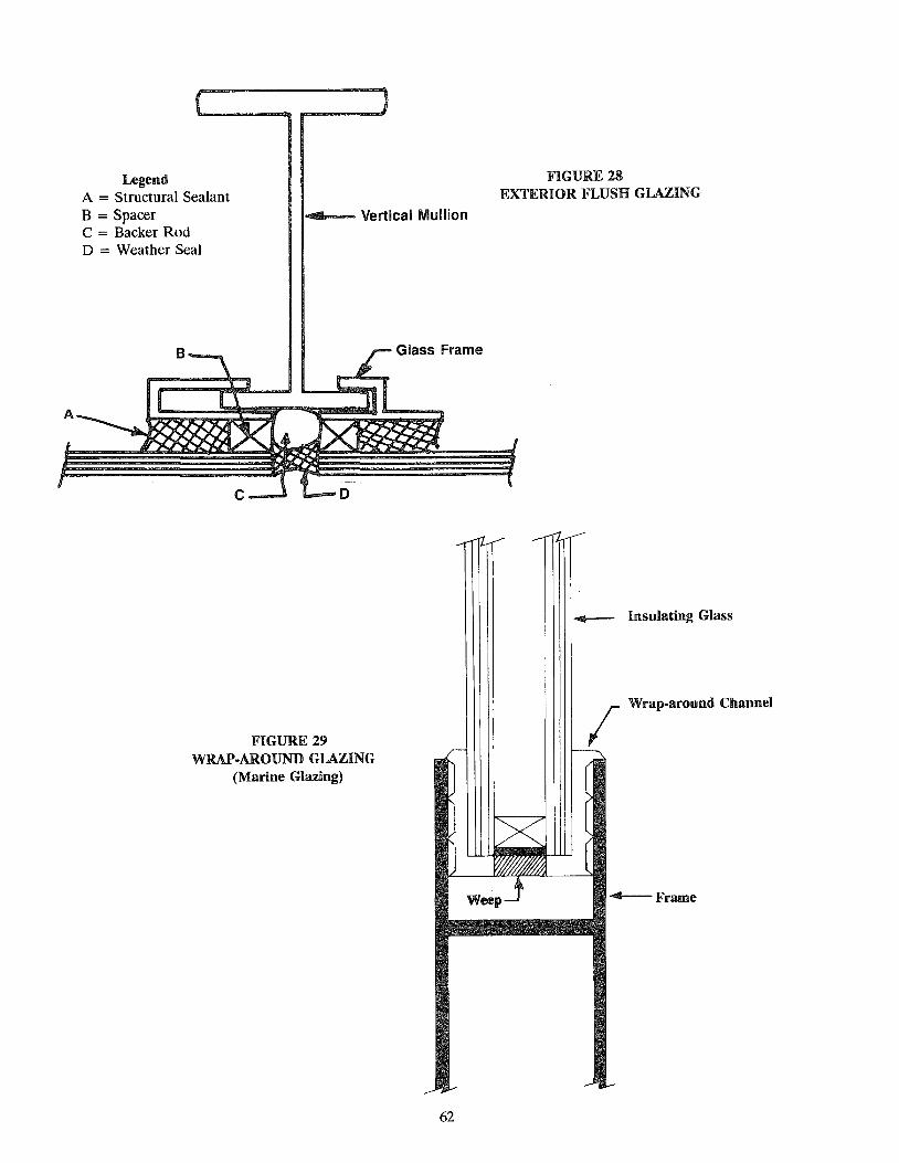
Legend A = Structural Sealant B = Spacer 14 ....... - Vertical Mullion C = Backer Rod D = Weather Seal
FIGURE 29 WRAP·AROUND GLAZING
(Marine Glazing)
62
FIGURE 28 EXTERIOR FLUSH GLAZING
~ Insulating Glass
I Wrap-around Channel
-4--Frame

SLOPED GLAZING
See Chapter V, Design Considerations, Sloped Glazing, page 25. The concept of two-sided structural silicone glazing, eliminating the horizontal battens on the purlins, is rapidly gaining acceptance in sloped glazing. One such design is shown in Figure 7, Chapter V. By the end of 1990, AAMA should have available "Skylight and Sloped Glazing Series, #2," dealing with proper steps for installing two-sided structural silicone glazing on sloped glazing applications.
Workmen must not be permitted to walk on, or to put their full weight on, sloping glass to drop added lites into place or to apply batten strips or sealants. The work should always be done from a temporary platform of plywood or other suitable material. The platform should not touch the glass when deflected nor should it rest directly on glass already in place. The platform should be secured by clamps, ropes or other appropriate means.
Refer also to "Cap Beads" is this chapter. Structural (lOCk-strip or zipper) gaskets are not recommended for use in sloped glazing systems. Adequate
water tightness and drainage are difficult to achieve.
BENT GLASS
Bent glass is frequently used as the transition lite from sloped to vertical glazing. As such, it can also be involved in the structural silicone glazing previously discussed in two sections of this chapter.
HANDLING Bent glass requires installers to exercise a higher level of care when handling the glass than when handling flat
glass. The center of gravity changes when glass is bent, which generally necessitates the use of additional manpower
to carry or set bent glass than when handling a lite of flat glass of similar size and thickness. The tighter the curve (the smaller the radius) ofbent glass, the greater the tendency of the lite to tip or be off
balance, possibly causing edge damage. Slings or power vacuum cups of a sufficient diameter and depth to produce a tight seal against the glass surface
should be used to handle larger bent lites. TOLERANCES
The tolerances generally observed in curving architectural glass and the framing system is generally one-eighth inch, plus or minus (+ 1/8"), for each radius. Although technology tOday is such that tolerances of delivered material are less, it is always well to state the allowable tolerances as part of a project specification by the architect and that a clear understanding of the expected tolerances be negotiated before a glazing contractor enters an order with a supplier.
GLAZING OPERATIONS When bent glass is installed with the curve in the vertical plane, Le., such as the rounded corner of a building,
three setting blocks should be used instead of the usual two. There should be the usual ones at the quarter points plus the added one at the mid-point of the curve. The blocks should be of a length comparable to those of a flat lite of glass and should be notched in several places to allow them to be bent to the same curvature at the glass.
When the bent glass is installed with the curve in the horizontal plane, as the eave at the transition of a slope to the vertical, the setting and edge blocks as specified for flat glass are recommended.
The accumulation of tolerances in bent glass and curved aluminum extrusions requires special consideration in selection of glazing stops and gaSket materials. The glazing rabbet must be sufficiently wide to allow for the attachment of the glass stop without placing stress on the glass. Stresses are additive; a pressure point created by glazing, with thermal, wind or snow loads added later, can cause spontaneous breakage in the future.
In a pressure plate system, the exterior gasket should be of a very soft, pliable material, more so than would be used in a flat glass installation. The pressure plate should be drawn to just hand-tight, where the gasket is just in contact with the glass surface on the exterior. Screws used to fasten the pressure plate should be of sufficient length to just bottom out, thereby preventing undue stress on the glass. A cap bead would then be in order to render the installation water tight.
The bending of architectural glass and aluminum is an important service to the glass and glazing industry. As happens in all specialized fields, terminology unique to the bending industry has developed over the years. Additionally, many common terms take on different meanings when used in reference to glass and metal bending.
To assist in understanding bent glass and metal and to accurately describe a project, the following is a glossary of bending terms.
63

CHORD The dimension of an imaginary straight line connecting the end points of a curve or arc. Sometimes referred to as the "point to point" dimension or measurement.
CONVEX When viewed from the EXTERIOR, the curve bends towards the observer.
T I
1'1 I I~ I L
HEIGHT The straight edge dimension or measurement of a lite of glass as opposed to the girth dimension or measurement. Could also be referred to as the WIDTH if the lite is installed in an overhead application
RISE In geometric terms, the rise is known as the height of the arc. While not critical when adequate information is submitted, the rise or height of the arc, when used in conjunction with the chord dimension, can be used to calculate an unknown radius and girth.
TANGENT A straight line coming out of an arc or curve. Sometimes referred to as a straight leg.
64
CONCAVE When viewed from the EXTERIOR, the curve bends away from the observer.
\~I , I , ,. , , .......... .-.'" ---_ ...
'K GIRTH
The length of the curve or arc required. The dimension or measurement of the material required if viewed in a "stretched-out" or "flattened" state.
RADIUS The dimension or measurement of an imaginary line taken from the center point of a circle to the arc or circumference of the circle.
CIRCUMFERENCE The length of a curve of arc of a circle.
DEGREE Every circle regardless of radius contains 360 degrees of arc or curvature. The girth or arc length of curved glass or aluminum can be determined when the "degree of arc" is given.
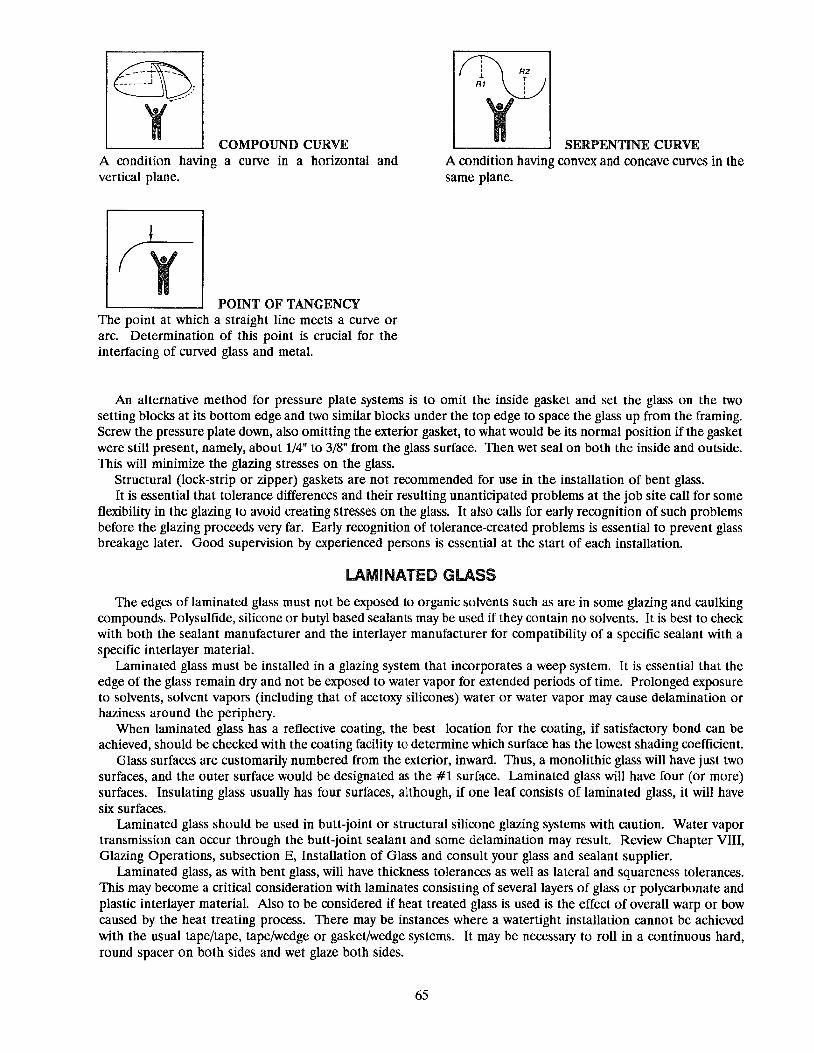
COMPOUND CURVE A condition having a curve in a horizontal and vertical plane.
POINT OF TANGENCY The point at which a straight line meets a curve or arc. Determination of this point is crucial for the interfacing of curved glass and metal.
r1\v: R2 .l T
R1 !
'1' SERPENTINE CURVE A condition having convex and concave curves in the same plane.
An alternative method for pressure plate systems is to omit the inside gasket and set the glass on the two setting blocks at its bottom edge and two similar blocks under the top edge to space the glass up from the framing. Screw the pressure plate down, also omitting the exterior gasket, to what would be its normal pOSition if the gasket were still present, namely, about 1/4" to 3/8" from the glass surface. Then wet seal on both the inside and outside. This will minimize the glazing stresses on the glass.
Structural (lock-strip or zipper) gaskets are not recommended for use in the installation of bent glass. It is essential that tolerance differences and their resulting unanticipated problems at the job site call for some
flexibility in the glazing to avoid creating stresses on the glass. It also calls for early recognition of such problems before the glazing proceeds very far. Early recognition of tolerance-created problems is essential to prevent glass breakage later. Good supervision by experienced persons is essential at the start of each installation.
LAMINATED GLASS
The edges of laminated glass must not be exposed to organic solvents such as are in some glazing and caulking compoundS. Polysulfide, silicone or butyl based sealants may be used if they contain no solvents. It is best to check with both the sealant manufacturer and the interlayer manufacturer for compatibility of a specific sealant with a specific interlayer material.
Laminated glass must be installed in a glazing system that incorporates a weep system. It is essential that the edge of the glass remain dry and not be exposed to water vapor for extended periods of time. Prolonged exposure to solvents, solvent vapors (including that of acetoxy silicones) water or water vapor may cause delamination or haziness around the periphery.
When laminated glass has a reflective coating, the best location for the coating, if satisfactory bond can be achieved, should be checked with the coating facility to determine which surface has the lowest shading coefficient.
Glass surfaces are customarily numbered from the exterior, inward. Thus, a monolithic glass will have just two surfaces, and the outer surface would be designated as the #1 surface. Laminated glass will have four (or more) surfaces. Insulating glass usually has four surfaces, although, if one leaf consists of laminated glass, it will have six surfaces.
Laminated glass should be used in butt-joint or structural silicone glazing systems with caution. Water vapor transmission can occur through the butt-jOint sealant and some delamination may result. Review Chapter VIII, Glazing Operations, subsection E, Installation of Glass and consult your glass and sealant supplier.
Laminated glass, as with bent glass, will have thickness tolerances as well as lateral and squareness tolerances. This may become a critical consideration with laminates conSisting of several layers of glass or polycarbonate and plastic interlayer material. Also to be considered if heat treated glass is used is the effect of overall warp or bow caused by the heat treating process. There may be instances where a watertight installation cannot be achieved with the usual tape/tape, tape/wedge or gasket/wedge systems. It may be necessary to roll in a continuous hard, round spacer on both sides and wet glaze both sides.
65

HEAT-TREATED GLASS
The surfaces of tempered and heat strengthened glass are in a state of extreme compression. Edge or surface damage, therefore, may more likely be the cause of future spontaneous breakage than if the lite were annealed. In the case of tempered glass, frequently not enough glass remains in the opening to define the break origin.
Every precaution should be taken to ensure that no damage occurs to the lite between the packing case and the completed, glazed opening.
Permissible bow and warp can be substantial on large lites. Consideration of this may require extra face clearance, dimension A, Figure 9, page 46. Review Chapter VIII, Glazing Operations, subsection E, Installation of Glass, page 43. Also see Table 5, page 16, Overall Bow Allowance.
INSULATING GLASS
The weep system must be open and the glazing rabbet free of all debris. Prolonged exposure to water or water vapor can cause failure of the organic edge seal.
Glazing materials must be resilient compounds whose compatibility with the edge seal has been previously established. Use of material of unknown compatibility is not acceptable. In general, any material containing more than 4% oils or solvents will probably be incompatible and will degrade the edge seals, causing failure.
Many glazing systems apply pressure to the edge of the glass to achieve a weather tight seal. This edge pressure should be a minimum of four (4) pounds and a maximum of ten (10) pounds per linear inch of perimeter and not bear on the marginal 1/8" of the unit glass surface. Excessive pressure can increase mechanical stresses and pOSSibly contribute to glass breakage.
Units having one lite of tinted or reflective glass should normally be installed with that lite to the exterior. When the tinted or reflective lite IS to be installed to the interior, it should be clearly called out in the plans and speCifications and have been the subject of a thorough study of edge stresses by the responsible design professional. Such studies may show a need to heat strengthen or temper one or both lites to minimize thermal breakage when the tinted or reflective lite is to the interior.
Units which will undergo a change of altitude greater than 2500' between point of fabrication and point of installation must have temporary breathers to permit pressure equalization. The difference in barometric pressure for a 2500' change is 1.335 psi, or 192 psf, the approximate equivalent of a 275 mph wind load. The breathers must be sealed within a few days after arrival at their destination, otherwise the desiccant will absorb excessive moisture, shortening the life of the unit. Note that gas filled units cannot be shipped with breathers; the gas would quickly escape. It is not practical to gas fill at a job site.
Job site procedures to overcome wintertime collapse of air space cannot be done to gas filled units. Again, the gas would quickly escape.
WRAP--AROUND (MARINE) GlAZING
Wrap-around glazing is a method of glazing that was originally used on power boat windows, hence, the name, "marine". From boats, it was adapted to patio doors, then to horizontal sliding windows. Originally it was used with monolithic glass because insulating glass wasn't used in these types of residential applications.
An extruded U-channel of vinyl or synthetic rubber is wrapped around the edges of the lite of glass or insulating unit. A single, butt-joint is made at the top center of the glass, the corners are partly slit to make the 90° turn. The extruded aluminum frame members are then forced onto the channel and screwed together at the corners; the framed lite is then ready to be installed into the main frame which has already been attached to the structure.
In theory, the slit corners of the wrap-around will provide drainage of any water that penetrates between glass and the U-channel. In real life, this is seldom adequate for insulating glass. The drainage is so slow that the infiltrated water has ample time to attack the seals of the insulating glass, resulting in premature failure of the unit. Holes of 1/2" to 5/8" diameter, punched 6" on center in the base of the U-channel have been found to provide adequate drainage in many instances. See Figure 29, page 62.
SPECIAL SYSTEMS
There are highly specialized glazing systems that have been developed for specific types of installations. Some of these are suspended glazing, commonly used to enclose grandstands at race tracks, glass mullion systems, special systems for racquetball courts, and others.
66

These have been designed, developed and tested by their originators and frequently have idiosyncracies that are not apparent in the literature or drawings. They should not be imitated without thorough testing of a full scale mockup, and if considered appropriate, by a wind tunnel test.
ACRYLIC & POlYCARBONATE SHEET
Plastic sheets are subject to greater dimensional change due to thermal expansion and contraction than most other materials with which they are commonly used in construction. Table 15 compares this characteristic.
TABLE 15 Comparison of Coefficients of Thermal Expansion
with other Building Materials
Inches per 10' length Inches/inch/oF lOO°F temperature change
Polycarbonates .0000440 .528" Acrylics .0000420 .504" Aluminum .0000129 .155"
Steel .0000063 .076" Glass .0000050 .060"
Plastic sheet has a relatively high rate of water vapor transmission, hence is not recommended for use as one (or both) lites of an insulating glass unit.
Most acrylic and polycarbonate sheets are classed as safety glazing materials as defined by CPSC 16 CFR 1201 and ANSI-Z97.1.
The glazing characteristics of these plastics are substantially different from those Of glass. Particular attention must be paid to expansion and contraction, adhesion and compatibility with glazing materials and preparation of the glazing rabbet, and especially to deflection if wind load is a consideration. The modulus of elasticity of polycarbonate is 345,000 and of glass is 10,400,000. If polycarbonate and glass of the same size and thickness are subjected to identical uniform loads, the deflection of the polycarbonate will be approximately 30 times that of the glass.
The following general recommendations should always be supplemented with the latest information available from manufacturers.
o Plastic sheets or panels should be installed, in a metal frame engaging the edges of the material, so that the material is free to expand and contract without restraint.
oThe rabbet depth should be sufficient to allow for the thermal contraction or deflection of the plastic without withdrawal of the edges from the frame.
-Through-bolting or other inflexible fastenings, which do not provide for expansion and contraction, can cause failure of the installation.
- Before installation in the metal frame, plastics should be cut sufficiently shorter than the channel frame dimensions to allow for thermal expansion.
-Sealant compounds and tapes should be types which are sufficiently extensible to accommodate thermal expansion and contraction and which adhere to both the plastic and frame.
- Depth and width requirements of the rabbet are determined by type, thickness and the wind load requirements. See plastic manufacturer's recommendations for minimum size limitations.
-Screw applied stops to the interior side of the sash may be applied tight against the plastic. It is not generally practical to apply snap-on glazing beads tight against the sheet. A bond breaker tape, applied to the stop, is recommended to avoid scratching of the plastic during normal thermal movements.
- It may be necessary to use setting blocks, with pressure equalization and weep systems, to prevent blockage of weep holes. It is also permissible to set the sheets directly on the bottom of the sill member.
- Wash with mild soap, detergent and water, or household ammonia and water. Use as much water as possible in washing. Apply to large areas with a bristle mop used in window washing and to smaller areas with a clean, soft cloth, sponge or chamois.
- If it is necessary to dry the washed surface, use a clean, damp chamois. - Abrasives will scratch the surface of acrylic plastic. The exercise of reasonable care in cleaning acrylic plastic
will minimize scratching.
67

ePolycarbonates and acrylics have about the same coefficient of thermal expansion. (Change in length = coefficient of expansion x length x°F. temperature change.) This is approximately eight times more than glass and three times more than aluminum. This high degree of thermal expansion and contraction results in much greater movements than glass. Therefore, careful consideration should be given when selecting the glazing system.
eSash designs suited for glass are not necessarily suited for glazing plastics. As the plastic sheet reaches 72" or more the bite increases, over what the glass bite is, on the same sash rabbet. The sealant dimension (face clearance) is also increased to accommodate the greater shear movement.
eGlazing systems should be installed in accordance with good glazing practices. eThere are coated plastics on the market which improve the scratch resistance by use of a transparent coating
applied to the acrylic or polycarbonate sheet. The resistance of such coatings to ultra-violet or atmospheric chemical degradation should be fully investigated prior to use.
iliA difference between temperature and/or humidity conditions, prevailing on opposite sides of a sheet, may cause the sheet to bow slightly toward the surface exposed to the higher temperature and/or humidity. However, the sheet will return towards its original condition as soon as the temperature or humidity differential has been reduced. This puts a great deal of stress on the glazing system.
III Plastic sheets with major dimension greater than 24 inches shall be installed with a continuous metal or wood bead. Glazing compound should never be used; only elastomeric sealants with adequate elongation characteristics and proven adhesions to the particular plastic substrate.
eAlI surfaces of wood and steel should be prime painted as required by the manufacturer before application of sealants. Aluminum sash should be cleaned with MEK Cleaner to remove protective finishes and grease. Under no circumstances should plastics be exposed to solvents such as Xylol, Toluol, MEK, etc. VM & P Naphtha can be used as an effective cleaner.
• If unusual loading, temperature, humidity or sash conditions exist, consult with plastic manufacturer for recommendations .
• Unmask plastic sheets before installing, immediately after cutting-to-size. -The edges of a plastic lite should be thoroughly cleaned before setting in sash with VM & P Naphtha. eProtect plastic from excess sealant smears with a paper-backed adhesive tape around the edges adjacent to
the rabbets. - Plastic glazing should be regarded as a finishing operation and should be scheduled as one of the last steps
in the completion of the building. If this is not practical, acrylic plastic should be protected from paint, plaster and tar splashes with drop cloths or other suitable covering.
MIRRORS
A number of options are available to securely and attractively mount an unframed mirror on a wall. The choice of the most acceptable technique will depend upon the type of wall construction, location and other factors. Some of the methods are:
Mastic: The use of mastic is desirable when the wall is not flat and cannot readily be made flat. The mastic must be compatible with the mirror backing and with the wall. Support at the bottom of the mirror is needed, such as a channel, clips, baseboard or splash. Clips also are advisable near the top to retain the mirror temporarily while the mastic achieves its cure. The mastic and the mirror should be applied to the wall in a manner that allows air movement vertically and permits condensation to escape.
Double Faced Tape: The tape must be compatible with the mirror backing and capable of bonding permanently to the wall. The tape should be at least 1/8" thick, applied vertically to the wall with the top of each strip trimmed to a point so condensation cannot collect on the upper edge of the tape. Apply the tape to the wall, locating the strips on the high points if possible. A tape with adhesive capability of two (2) pounds for every one (1) square inch of tape is recommended. The bottom of the mirror should be supported by clips, a channel, a splash or baseboard. Space should be allowed at the bottom for vertical air movement.
Skeleton Wood Back: Since wood strips fastened to a wall can be shimmed with shingles to bridge irregularities in the wall, this method offers the best possibility of getting a perfectly plumb-and-in-plane installation. Nominal 1" x 2" lumber is usually adequate. The wood should be prime painted before being mounted on the wall, thus eliminating possible interaction between resins in the wood and the mirror backing. After the skeleton is installed, any of the following types of mounting the mirror may be used.
68

Channel & Clips: A continuous channel across the bottom of the mirror must be anchored securely to the wall because it will carry the weight of the mirror. Metal or plastic clips, securely fastened into the wall can then be used to complete the installation. If metal clips are used, a felt or plastic pad should be placed between the mirror and each clip to prevent spalling the edges of the mirror. Two 1/8" x 4" setting blocks should be in the channel at the quarter points and two 1/4" weeps drilled between.
Rosettes or Screws: Mirrors up to ten (10) square feet are generally mounted by a hole in each of the four corners. Over ten square feet, holes are advised on approximately 36" centers. All holes should be a least 4" from an edge. This is the most difficult method of mounting a mirror directly onto a wall. If the wall is irregular and a rosette or screw is slightly over-tightened, it can cause the mirror to crack at a hole. Holes in the mirror should be at least 1/8" larger than the shank of the screw or rosette shank, to accommodate a plastic or rubber sleeve. A felt or plastic cushion should be between the rosette and the mirror.
Metal Frames: Metal framed mirrors seldom offer mounting problems because the frame protects the edge of the glass.
General Precautions: Mirrors should not be mounted directly against unpainted plaster, wood, plywood, concrete or concrete block walls. These surfaces must be painted to prevent potential damage to the mirror.
Mirrors should be mounted plumb and in-plane to avoid distorting reflected images. Space for air circulation and elimination of condensation should always be provided between the back of the
mirror and the wall.
69

,.. " r: - N" x r ~
'c, '" """ ' ", ,','~. ~~~SS~Hn~, , ' "', ::t~ 1" ~ ~: p -" ~"~ '" ~(",",,~ T.l1: _""
Acid Polishing The polishing of a glass surface by acid treatment.
Annealing The process of preventing objectionable stresses in glass during manufacture by controlled cooling. Re
annealing is the process of removing objectionable stresses in glass by re-heating to a suitable temperature followed by controlled cooling.
Anti-Walk Blocks Rubber blocks that prevent glass from moving sidewise in the glazing rabbet from thermal effects or vibration.
See Edge Blocks, Figure 12.
Autoclave A vessel that employs high pressure and heat. In the glass industry, used to produce a bond between glass and
PVB or urethane sheet, thus creating a laminated glass product.
Back Putty (See Bed)
Back-up A material placed into a joint, primarily to control the depth of the sealant and to prevent adhesion at the base
of the sealant bead.
Batter A surface defect that looks like hammered metal. Unless very heavy, it usually cannot be seen by the naked
eye, although it is clearly seen on the shadowgraph (see Shadowgraph).
Bead A sealant after application in a joint irrespective of the method of application, such as caulking bead, glazing
bead, etc. also a molding or stop used to hold glass or panels in position.
Bed or Bedding (also Back Putty) In glazing, the bead of compound applied between a lite of glass or panel and the stationary stop or sight bar
of the sash or frame. It is usually the first bead of compound to be applied when setting glass or panels.
Bedding of Stop In glazing, the application of compound at the base of the channel, just before the stop is placed in position,
or buttered (see buttering) on the inside face of the stop.
Bent Glass Flat glass that has been Shaped while hot into cylindrical or other curved shapes.
Bevel of Compound Bead In glazing, a bead of compound applied to provide a slanted top surface so that water will drain away from the
glass or panel.
Beveling The process of edge finishing flat glass to a bevel angle.
Bite Amount of overlap between the stop and the panel or lite.
Blisters Relatively large bubbles or gaseous inclusions in the glass. Blisters differ only in degree from seeds, which are
extremely small gaseous inclusions. Sometimes bubbles less than 1/16" in diameter are considered to be seeds, while anything larger is a blister. Except from the standpOint of appearance, seeds and blisters are usually quite harmless.
Block A small piece of lead, rubber or other suitable material used to position the glass in the frame.
Bloom A surface film on glass resulting from attack by the atmosphere, or by deposition of smoke or other vapors.
70

Bow A continuous CUlve of the sheet, either vertical or horizontal.
Bronze Glass A glare and heat-reducing glass which is intended for applications where glare control and reduction of solar
heat is desired or where color can contribute to design.
Brush Lines Fine parallel surface lines having the general appearance of brush marks in paint. Also called "end lines."
Bubbles Gaseous inclusions in glass. These inclusions are practically always brilliant in appearance. The term is applied
to all such inclusions larger than 1/32" in maximum dimension. The term "small bubbles" refers to the sizes between 1/32" and 3/32".
Bulb Edge In float glass manufacture, the extreme lateral edge of the ribbon as drawn.
Bullet Resisting Glass A multiple lamination of glass with tough clear sheet plastic usually at least 1-3/16" thick overall, which is
designed to stop bullets from ordinary firearms other that high powered rifles.
Buttering Application of sealant compound to the flat surface of some member before placing the member in pOSition,
such as the buttering of a removable stop before fastening the stop in place.
Casting Shaping glass by pouring it into or on molds, tables, or rolls.
Channel A three-sided, V-shaped opening in sash or frame to receive lite or panel, as with sash or frame units in which
the lite or panel is retained by a removable stop. Contrasted to a rabbet, which is a two-sided L-shaped opening, as with faced glazed window sash.
Channel Depth The measurement from the bottom of the channel to the top of the stop, or measurement from sight line to
base of channel.
Channel Glazing The sealing of the joints around lites or panels set in V-shaped channel employing removable stops.
Channel Width The measurement between stationary and removable stops in a V-Shaped channel at its widest point.
Checks (Vents) Very small cracks in flat glass, usually at the edge. Though small, these are cause for concern since they can
be intensified under strain.
Chemical Durability The lasting quality, both physical and chemical, of a glass surface. It is frequently evaluated after prolonged
weathering or storage, in terms of physical and chemical changes in the glass surface. See "Weathering."
Chipped Edge An imperfection due to breakage of a small fragment from the cut edge of the glass. Generally this is not
serious except in heat absorbing glass.
Clips Wire spring devices to hold glass in rabbeted sash, without stops, and face glazed.
Compound A formulation of ingredients, usually grouped as vehicle or polymer pigment and fillers to produce caulking
compound, elastomeric joint sealant, etc.
Compression Pressure exerted on a sealant in a joint, as by placing a lite or panel in place against bedding, or placing a stop
in position against a bead of sealant.
71

Consistency Degree of softness or firmness of a compound as supplied in the container and varying according to method
of application, such as gun, knife, tool, etc.
Cords Attenuated glassy inclusions that possess optical and other properties differing from those of the surrounding
glass. Cords are the result of non-homogeneity. Low intensity cords are called strings or wire lines.
Crush A lightly pitted area resulting in a dull gray appearance over the region.
Cullet Broken glass, excess glass from a previous melt, or edges trimmed off when cutting glass to size. Cullet, in some
regular proportion, is an essential ingredient in the raw batch charge in glass-making in that it facilitates melting.
Curing Agent One part of a two-part sealant which when added to the base will cause the base to change its physical state
by chemical reaction between the two parts.
Cut Sizes Glass ordered with width and length specified, and not as stock sheets. Cut sizes are furnished with sizes
guaranteed to be cut to at least the dimensional tolerances stipulated.
Cutter One who cuts flat glass. Also, the tool used in cutting glass.
Cutting Scoring flat glass with a diamond or a steel or hard alloy wheel and breaking it along the score.
Decolorizer Material or agent used in the batch to remove color, or to decolorize glass.
Decolorizing The process of producing a colorless appearance in glass.
Devitrification Crystallization in glass.
Dice The more or less cubical pattern of fracture of fully tempered glass, the edges of the dice being roughly equal
to the thickness of the glass.
Diffusing Scattering, dispersing, as the tendency to eliminate a direct beam of light.
Digs Deep, short scratches.
Dirt A small particle of foreign matter imbedded in the glass surface.
Distortion The characteristic surface waviness of glass. It is often confused with "brush lines" and "end lines" but is not
at all related. Seldom met within an objectionable degree, it can be evaluated on the shadowgraph.
Double Strength In float glass, approximately 1/8" thick.
Dryseal Accomplishment of weather seal between glass and sash by use of Neoprene (or other flexible material) strips
or gaskets. A dry seal may not be completely watertight.
Durometer A machine to measure shore hardness. (See shore hardness.)
Edging Grinding the edge of flat glass to a desired shape or finish.
72

Elastomer An elastic, rubber-like substance, as natural or synthetic rubber.
Emissivity The ability of a material to emit radiant energy. Emittance is the ratio of the total radiant energy emitted by
a given surface to that emitted by an ideal black body at the same term perature. To emit is to give out, to discharge, in the case of glass, essentially, to reradiate absorbed energy (heat).
Etch To attack the surface of glass with hydrofluoric acid or other agent, generally for marking or decoration.
Exterior Glazed Glass set from the exterior of the building.
Exterior Stop The removable molding or bead that holds the lite or panel in place when it is on the exterior side of the lite
or panel, as contrasted to an interior stop located on the interior side of the lite.
Face Glazing On rabbeted sash without stops, the triangular bead of compound applied with a glazing knife after bedding,
setting, and clipping the lite in place.
Figured Glass Rolled glass having a patterned or figured surface. Most patterns can be obtained with one side smooth fire
polished (Le., "as rolled"). Some patterns are available with both surfaces figured.
Fire-Polish To make glass smooth or glossy by the action of fire.
Flare A protrusion on the edge of a lite of glass due to improper cutting.
Flat Glass A general term that embraces float glass and various forms of rolled glass (as contrasted with fibre glass,
containers, etc.).
Float Glass Glass drawn over a bath of molten tin to attain a fire polish.
Front Putty In glazing, the putty forming a triangular fillet between the surface of the glass and the front edge of the rabbet.
Frosted Finish A surface treatment for glass, consisting of an acid etChing of one or both surfaces that improves distribution
of transmitted light and reduces glare.
Fully. Tempered Glass Glass that has been tempered to a high degree. Specified by ASTM C 1048 (KIND FT) as having a surface
compression of not less than 10,000 psi or an edge compression of not less than 9,700 psi. Fully tempered glass, if broken, will disintegrate into many small pieces (dice) which are more or less cubical. Fully tempered glass is four to five times stronger than annealed glass of the same thickness.
Gaseous Inclusions Round or elongated bubbles in the glass.
Gaskets Pre-formed shapes, such as strips, grommets, etc., of rubber or rubber-like composition, used to fill and seal
a joint or opening either alone or in conjunction with a supplemental application of a sealant.
Gauge (Verb) To measure the thickness of flat glass. Also, (noun), refers to the thickness of the glass. See "Strength."
Glass An inorganic product of fusion which has cooled to a rigid condition without crystallizing. It is typically hard
and brittle and has a conchoidal fracture. It may be colorless or colored, and transparent to opaque. Masses or bodies of glass may be made colored, translucent or opaque by the presence of dissolved, amorphous, or crystalline material.
73

Glazing The securing of glass in prepared openings in windows, door panels, partitions, etc.
Glazing Quality In float glass, this represents the usual selection supplied when quality is not otherwise definitely specified.
Gray Glass See "Bronze".
Gun Consistency Sealant formulated in a degree of softness suitable for application through the nozzle of a caulking gun.
Heat-Absorbing Glass Glass for intercepting appreciable portions of radiant energy, especially solar energy, in specific transmittance
values as defined in ASTM C 1036. It is obtainable as float and patterned glass. Heat-absorbing glass is made in only one quality in type of glass. See "Bronze" and "Gray Glass".
Heat-Resisting Glass Glass able to withstand high thermal shock, generally because of low coefficient of expansion.
Heat-Strengthened Glass Glass that has been heat-treated to a state less than that of fully tempered glass. Specified by ASTM 1048
(Kind HS) as having a surface compression of not less than 3,500 psi or greater than 10,000 psi or an edge compression of not less than 5,500 pSi. Heat-strengthened glass is approximately two times as strong as annealed glass of the same thickness and has a much increased thermal endurance. Heat-strengthened glass is not considered a safety glass and will not completely dice as will fully tempered glass.
Heat-Treated Term sometimes used for both fully-tempered glass and heat-strengthened glass.
Heel Bead Sealant applied at the base of channel, after setting lite or panel and before the removable stop is installed; one
of its purposes being to prevent leakage past the stop.
High-Transmission Glass Glass which transmits an exceptionally high percentage of visible light.
Interior Glazed Glass set from the interior of the building.
Interior Stop The removable molding or bead that holds the lite in place, when it is on the interior side of the lite, as
contrasted to an exterior stop which is located on the exterior side of a light or panel.
Kink Similar to "wart" but of shorter distance between high and low points of deviation from plane. Usually
associated with vertically tempered glass.
Knife Consistency Compound formulated in a degree of firmness suitable for application with a glazing knife such as used for face
glazing and other sealant applications.
Knot An imperfection in glass; an inhomogeneity in the form of a vitreous lump.
Lehr A long, tunnel-shaped oven for annealing or reannealing glass, usually by continuous passage.
Lime Glass The most commonly melted form of clear, uncolored flat glass, so called because a principal ingredient, besides
sand, is lime (CaO).
Lines See "Brush Lines," "Cords," and "Ream".
74

Lite Another term for a pane of glass used in a window. Sometimes spelled "light" in the industry literature, but
spelled "lite" in this text to avoid confusion with light as in "visible light". ASTM has officially adopted "lite" as proper in all their documents.
Low·E or Low Emissivity Is to have a low rate of emitting (radiating) of absorbed radiant energy. The radiant energy (heat) is, in effect,
reradiated back toward its source.
Mastic Descriptive of heavy-consistency compounds that may remain adhesive and pliable with age.
Non-Drying DeSCriptive of a compound that does not form a surface skin after application.
Patterned Glass (Sometimes called Rolled or Rough Rolled Glass) One type of rolled glass having a pattern impressed on one or both sides. Used extensively for light control
and decorative glazing.
Points Thin, flat, triangular or diamond Shaped pieces of zinc used to hold glass in wood sash by driving them into the
wood.
Polariscope A device for examining the degree of strain in a sample of glass.
Polished Wired Glass Wired glass that has been ground and polished on both surfaces.
Polybutene Base Compounds made from polybutene polymers.
Polymer A chemical structure consisting of long chains of molecular units.
Polysulfide Base Compounds made from polysulfide synthetic rubber.
Priming Sealing of a porous surface so that compound will not stain, lose elasticity, shrink excessively, etc., because of
loss of oil or vehicle into the surround. A sealant primer or surface conditioner may be used to promote adhesion of a curing type sealant to certain surfaces.
Processed Glass Glass in which the surface has been altered by etChing, sandblasting, chipping, grinding, ceramic-enameling, etc.
to change its light diffusion or to give decorative effects. Either or both surfaces may be so treated. Also glass which has been further treated (edge work, tempered, stained, etc.) after forming.
Rabbet A two-sided L-shaped recess in sash or frame to receive lites or panels. When no stop or molding is added,
such rabbets are face glazed. Addition of a removable stop produces a three-sided U-shaped channel.
Reflective Glass Glass with a reflective surface film to reduce heat and light transmission.
Roll Impressions Indentations in the surface of rolled glass, with or without an asbestos mark in the center, that are caused by
contact of the glass with the rolls and/or displaced roll disks while the set is in a plastic state.
Roll Marks (also Roll Scratches) A series of the fine parallel scratches or tears on the surface of rolled glass in the direction of draw. They are
1/8" long or smaller, but usually so fine and so close together that they appear to be a series of incipient checks rather than scratches. They are caused by a difference in velocity between rolls and the sheet of glass.
75

Rolled Glass Glass formed by rolling, including patterned and wired glass. As the glass is drawn horizontally from the tank,
figured, engraved, etched, machine rolls impress a pattern on the surface of the glass, varying from almost smooth to deeply marked geometric, fluted or random overall designs. It is made in thicknesses from 1/8" to 3/8".
Rub (also Crush) A series of small scratches in glass generally caused during transport by a Chip lodged between two lites.
Sandblasted Finish A surface treatment for flat glass obtained by spraying the glass with hard particles so as to clip out and
roughen one or both surfaces of the glass. The effect is to increase obscurity and diffusion, but make the glass fragile and hard to clean.
Sash The frame, including muntin bars when used, and including the rabbets to receive lites of glass, either with or
without removable stops, and designed either for face glazing or channel glazing.
Scratches Any marking or tearing of the surface appearing as though it had been done by either a sharp or rough
instrument.
Screw-On Bead or Stop Stop, molding or bead fastened by machine screws as compared with those that snap into position without
additional fastening.
Sealant Compound used to fill and seal a joint or opening, as contrasted to a sealer which is a liquid used to seal a
porous surface.
Seam (verb) To grind, usually with an abrasive belt, wet or dry, the sharp edges of a piece of glass. Also called "swipe."
Seeds Minute bubbles less than 1/32" in diameter. Fine seeds are visible only upon close inspection, usually appearing
as small specks, and are an inherent defect in the best quality of float glass. Seeds about 1/64" to 1/32" in diameter are usually considered as coarse seeds.
Setting Placement of lites or panels in sash or frames. Also action of a compound as it becomes more firm after
application.
Shading Coefficient See page 28, Solar Heat Gain, Chapter V.
Shadowgraph A device for examining glass with respect to distortion, batter and lines, although other defects are also
prominently revealed.
Shelf Life Used in the glazing and sealant business as referring to the length of time a product may be stored before
beginning to loose its effectiveness. Manufacturers usually state the shelf life and the necessary storage conditions on the package.
Shore Hardness Measure of firmness of a compound by means of a Durometer Hardness Gauge (Range of 20-25 is about the
firmness of an art gum eraser. Range of 90 is about the firmness of a rubber heel.)
Sight Line Imaginary line around the perimeter of lites or panels corresponding to the top edge of stationary and
removable stops, and the line to which sealants contacting the lites or panels are sometimes finished off.
Size of Bead Normally refers to the width of the bead, but there are many situations in which both the width and depth
should be taken into account in design, speCification, and application.
76

Slip Sheet The interleaving paper placed between lites of glass in a package to protect them from scratching and fade (also
called paper-packed).
Smoke Streaked areas appearing as slight discoloration.
Solarization Change in transmission and sometimes color, of glass as a result of exposure to sunlight or other radiation.
Spacers (Shims) Small blocks of composition, neoprene, etc., placed on each side of lites or panels to center them in the channel
and maintain uniform width of sealant beads. Prevent excessive sealant distortion.
Stain Attack of a glass surface by water or other solutions involving:
a. Leaching of sodium ions to the surface of the glass b. An increase in pH on the glass surface c. The breaking of silica bonds in the glass structure
If this process advances to c, above, the glass will have a blotched, streaked, cloudy appearance and cannot be restored to pristine condition short of grinding and polishing the damage away, a process that is generally more expensive than simply replacing the glass.
Stationary Stop The permanent stop or lip of a rabbet on the side away from the side on which lites or panels are set.
Stones Crystalline contaminations in the glass, usually pieces of undissolved or crystallized silica, bits of refractory, or
crystals due to devitrification. Stones are detrimental to appearance and may seriously weaken the glass, particularly if present in highly stressed areas.
Stop Either the stationary lip at the back of a rabbet, or the removable molding at the front of the rabbet, either or
both serving to hold lite or panel is sash or frame, with the help of spacers.
Strain Elastic deformation due to stress.
Stress Any condition of tension or compression existing within the glass, particularly due to incomplete annealing,
temperature gradient, or inhomogeneity.
Striking Off The operation of smoothing off excess compound at sight line when applying compound around lites or panels.
String Transparent lines appearing as though a thread of glass has been incorporated into the sheet. See "Wire Line."
Structural Silicone Glazing Is based upon the use of a silicone sealant not only as a weather seal but also for the structural transfer of loads
from the glazing panel to its perimeter support system. Certain specific silicone sealant formulations are the only sealants, to date, found to be suitable for this ppurpose.
Tempered Glass Glass that has been rapidly cooled from near the softening point, under rigorous control, to increase its
mechanical and thermal endurance. Fully tempered glass always "dices" into a multitude of small particles. See pages 6 & 7.
Thermal Endurance The relative ability of glass to withstand thermal shock.
Tinted Glass Glass with a material added to give the glass a light and/or heat reducing capability and color. See "Bronze"
Glass.
77

Tong Marks Small, surface indentations near and parallel to one edge of vertically-tempered or heat-strengthened glass
resulting from the tongs used to suspend the glass during the heat treating process.
Transmittance The ability of the glass to transmit solar energy in the visible light, the ultra-violet, and infrared ranges, centrally
measured in percentages of each.
Unit Term normally used to refer to one single assembly of insulating glass.
United Inches Total of one width and one height in inches.
Vehicle The liquid portion of a compound.
Vents (See Checks)
Vinyl Glazing Holding glass in place with extruded vinyl channel or roll-in type.
Warp The easily seen undulate deviation of the sheet from a plane surface. MiCroscopic deviation would be
"distortion" or "batter." See "Kink."
Wave An optional effect due to uneven glass distribution or low-intensity cords.
Weathering (also Stain) Attack of a glass surface by atmospheric elements. (See "Chemical Durability")
Weeps Drain holes in the sash to prevent water accumulation, condensation, rain, cleaning, etc.
Wet Seal Application of an elastomeric sealant between the glass and sash to form a weather-tight seal.
Wire Line (also String) An attenuated, glassy inclusion that possesses optical and other properties that differ from the parent glass.
It is generally in a straight line parallel to the direction of draw, and associated with partially or completely dissolved stones.
Wired Glass, Flat Rolled glass having a layer of meshed or stranded wire completely imbedded as nearly as possible to the center
of thickness of the sheet. This glass is obtainable as polished glass (one or both surfaces) and patterned glass. Approved wired glass is used as transparent or translucent fire retardant glazing; sometimes as decorative glass or as security glazing. It breaks more easily than unwired glass of the same thickness, but the wire restrains the fragments from falling out of the frame when broken.
Work Life The time during which a curing sealant (usually 2 compounds) remains suitable for use after being mixed with
a catalyst.
78


Products, asplJJit roofing
advantages of 5-(,
components of 1 fire resistance 26
IllanuElcturillg
asphalt 7-K process 7, <)-10 qU,llity control 11
research 12 roofing fabric 40 selection of 25 storage of 11
types of I
Projected Horizontal Area
31-32 r~adiant Barrier Decks 18-19 Rag Felt. SCI' 13<1se Material:
01:~t111i(
Reroofing
bridging 75 deck prep,uation 67-6<)
fbshing
chimneys 74 eaves flashing 71 soil stIcks 74 valley flashing 73 vent pipes 74 vertiCIl sidewall (over
;lsphalt shingles) 73 vertiul sidewall (over
wood shingles) 73-74 nestinij 75 over existing roof
old asphalt shingles 69
old built-up roots 71 old roll roofing 7() old slate roofs 70-71 old wood shingles 7()
removing existing roof 68-6<)
shingle application
at hips and ridges 75 first course 72 metric shingles 75 second and succeeding
courses 73 starter strip 72
underlaymellt 71
Roll Roofing
application parallel to eaves
concealed nail method
80-81 exposed nail method
82-83 application parallel to rake
84 double coverage. See Double
COl/cragc Roll R""fi/l<~ specifications of
coverage 3, 25
exposure 3, 25 weights and measures 3
types of mineral surf,1Ced 3-4 smooth surf;lced 3-4
usage and handling 79 Roof Styles 17 Roofing Machine 9-10 Roofing Nails
corrosion resistance 20 length of 20 power milers 38-3<)
quantity and placement of
(strip shingles)
at hips and ridges 61 in high wind regions 23 under normal
conditions 22
recolllmendations 21 specifications of 20-21
Safety 37 Saturated Felt. Sec Under/ay/l1C1/t Self-Adhered Eave and Flashing
Membranes 3, 5
Shed Roof 17 Shingles
aesthetics (appearance) 27 alignment of. Sec Chalk Lines application ([ow slope) 65 application (new construction)
4" method 49 5" method 48-49 6" method 47-48 first and succeeding
courses 47 hips and ridges 60-61
1997 Edition Residential Asphalt Roofing Manual

Residential Asphalt Roofing Manual
Shingles (continued) in closed cut valley 52-53 in open valley 49-50 in open valley for donner roof 50-52 in woven valley 53-54 prep,mtion 45-46
starter strip 46-47 application (steep slope)
65-66 color shading 27-28, 92 factory-applied adhesive 26
hand sealing 26-27 specifications of
coverage 25 exposure 2, 23 \veights and 111CaSl1res 2
storage of 23-24 types of
Slope
giant individual 77-78 hcxagol1Jl 77
illterlocking 2, 4, 78 bmimted 2, 4 strip 1-4
calcubtion of 30-31
requirements for roll rootIng 17 shingks 16-17
Storage
shingles 23-24
Tape, Roofing. Sec Prodllcts, asplwlt 1'00jill.Q: roofin.~j(d)/'/·c
Three-dimensional shingles. Sec Shingles: types or lall/i/lated
Tools 38-39 UnderiaYlllent. Sec also noll
Rooji/l!<! application
low slopes 63 new construction 41-42
reroofing 71 usage of 5 '",eights and measures 3
Valleys flashing in
closed cut valleys 45 open valleys 44-45
woven valleys 45 shingle application in
closed cut valleys 52-53 open valleys 49-50
open valleys for dormers 50-52 woven valleys 53-54
Vapor n .. ctarlbtiOIl 41 Ventilation
heating ,md cooling costs, cffc'cts Oil 15-1 ()
practices 16 Wind ResistmccI3-14, 2()-27
Wood Saddle. Sec Crir/..:ei
1997 Edition


![Earthrise [1990] [Interstel Corporation] [Manual]](https://img.pdfslide.us/doc/110x75/55cf96b1550346d0338d29e4/earthrise-1990-interstel-corporation-manual.jpg)