Embed Size (px)
DESCRIPTION
Facts and hvdc light for power system interconnections
Citation preview
Presented at PowerDeliveryConfrerence, Madrid, Spain,September 1999
FACTS AND HVDC LIGHT FOR POWER SYSTEM INTERCONNECTIONSRolf Grünbaum, Bruno Halvarsson, Aleksander Wilk-Wilczynski
ABB Power Systems AB, Sweden
IntroductionThe deregulation of the electricity market together with increasing constraints resulting from social opposition tothe installation of new facilities puts new demands on the operators of transmission and distribution systems.These new trends enhance the need for flexibility, power quality and increased availability of transmission anddistribution systems by using tools which can be implemented with limited investments, short delivery times andshort planning and decision making horizons. FACTS (Flexible AC Transmission Systems) is a term denoting awhole family of concepts and devices for improved use and flexibility of power systems. Some of these deviceshave today reached certain maturity in their concept and application, some are as a matter of fact quiteestablished as tools in power systems. This paper will treat benefits of FACTS devices applied in power systemssuch as increased power transmission capability, improved static and dynamic stability, an increase of aavailability and a decrease of transmission losses. Examples will be given of FACTS devices which have reacheda more or less commercial degree of applicability in power systems, salient design features of these as well asoperational experience. The paper also treats HVDC Light, a new DC transmission system technology, stillconsisting of well-known components forming the system. HVDC Light is very suitable for DC powertransmission for a number of applications, as will be highlighted in the paper.
New approach to development of transmission networks
The traditional way to develop the transmission network in order to achieve better linkage between generationand demand was to reinforce of the grid, mainly by installing new lines and substations.
However, in recent years substantial changes were implemented in the traditional structures of electric powersystems throughout the world. The general reason for this is to improve efficiency, and the main tools arederegulation and privatization i.e. the introduction of market rules to the electrical sector. In consequence thetransmission system must be adapted to the new conditions of open access and open trading. This adaptationrequires the construction of new interconnections between regions and countries. The other important element isthe necessity to adapt transmission systems to changing generation patterns.
Manufacturers of electrical equipment must be prepared to meet these new requirements, where relocatabilityand flexibility will be the critical factors.
The flexibility of the system also means shorter planning and decision-making, with the consequence that shorterdelivery times are requested.
Practical examples of how these new requirements can be satisfied by using new types of equipment aredescribed below.
Significance of reactive power compensation
Transmission of electric energy at EHV (extra high voltage) over a long distance by means of alternating current(AC), requires some kind of reactive compensation. This is due to the inherent distributed series reactance andshunt susceptance of the long AC transmission line. If suitable means for reactive compensation are not installed,operation of the EHV power system for different steady state and dynamic conditions becomes difficult and evenimpossible.
Basically, reactive compensation may be applied to the power system in two ways: series compensation andshunt compensation. Usually, shunt compensation is employed for voltage control and series compensation tocontrol the longitudinal behavior of the network.
The series capacitor is a special case of controlling the power transmission system through control of alongitudinal element, i.e. an element that is placed lengthwise in the transmission line. This is in contrast to shuntelement controls, such as the control of generation, of loads or using static var compensators. However, each typeof compensation affects, to some extent, both the voltage control and the stability limit. In an actual long distanceEHV AC transmission system, means for series and shunt compensation are often combined in order to achievethe optimal result.
Application of Series Capacitors
The property of the series capacitors is that it provides a method of controlling the longitudinal behavior of thenetwork while providing reactive power. This form of compensation is very effective in certain situations. TheSeries Capacitor reduces the total reactance of a transmission line and thus makes the line electrically shorter.
To summarize, the main reasons for incorporating series capacitors in transmission systems will be:
- To increase the power transfer capability as a result of raising the transient stability limit- To improve the voltage profile of the system- To reduce transmission system losses by optimizing the sharing of active power between parallel lines- To reduce the cost of power transmission by making power transfer with fewer parallel lines and less
required shunt compensation possible.
Series compensation in a system improves voltage control and reactive power balance because the reactive powergeneration in a series capacitor increases as the transmitted power increases. In this respect, the series capacitor isa self-regulating device.
The important features of series capacitors as a part of the transmission system is high reliability and properprotection arrangement. High reliability means that the series capacitor is designed in such a way that itsavailability is at least as great as that of the other vital parts of the system (lines, breakers, transformers, etc.).
The protection demand implies that the series capacitor has to be provided with a protective system whichquickly and safely by-passes the capacitor in a situation where faults in the surrounding parts of the powersystem give rise to conditions which might cause damage to the series capacitor. However, the same protectivesystem also has to allow the series capacitor to be reinserted into the power system with a minimum of delay assoon as the fault in the surrounding network has been cleared.
The capacitors are often located along the lines, and switched as part of the lines. The choice of location mayrequire a special study in each particular case, with respect to overall economy and system reliability. The degreeof compensation usually lies between 20 and 70 %, as referred to the line inductive reactance. EHV seriescapacitor installation usually range in size between 100 Mvar and 1000 Mvar.
The technology involved in series compensation has undergone dramatic development in recent years. Not onlycapacitors themselves, which have improved greatly over the years as regards reliability, power density andlosses, but also associated equipment such as protective devices, control systems, etc. In the field of protection,zinc oxide (ZnO) technology has brought new possibilities of high reliability and reinsertion speed. The triggeredspark gap has enabled more cost-effective design of the ZnO protection at high fault levels. As regards thecontrol system, fiber optic signal communication and computerized control equipment have opened a wide rangeof features for series capacitor application today and in future.
By utilizing series capacitors, fewer parallel lines are required and construction of new lines can be postponed ormade unnecessary altogether. Investing in a series capacitor as an alternative to a new line will often proveprofitable, in more than one way:
- Investment cost is only a fraction of the line cost, lead times are much shorter and right of way problems canbe avoided
Series capacitor technology is well proved today as part of subtransmission and transmission systems up to 800kV. More than 100.000 Mvar of series capacitors are in operation or under construction all over the world.
Application examples
400 kV transmission system in Sweden
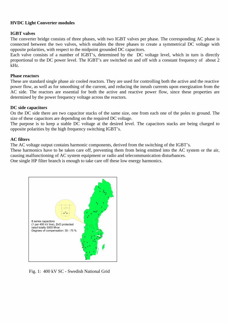
The 420 kV transmission system between Northern and Middle Sweden comprises 8 lines with altogether 8Series Capacitors, having a total rating of 4800 Mvar. See Fig. 1. The degree of compensation k (k = XC / XL) forthe individual Series Capacitor Banks, has been selected in such a way, that the sharing of active load (realpower) between the individual 420 kV lines, which are of different designs, and the parallel connected 245 kVnetwork, became most favorable. In the optimum point, minimum losses for the total network is obtained. Thereduction in losses, compared to the uncompensated case, has alone paid for the Series Capacitor investment in afew years. Another benefit of the Series Capacitors in the Swedish 420 kV network is the ability to supplyreactive power and support the voltage during and after a large disturbance.
The selected degree of compensation is between 30 – 70 % for the individual banks. With this compensation,stable transmission of more than 7000 MW on 8 parallel lines is achieved. This means, that the lines are loadedup to or > 2 x SIL (Surge Impedance Loading). Without Series Compensation five additional lines would havebeen needed to transmit the same amount of power. This, of course, would have been unpermissible, not onlyfrom an investment point of view, but also with respect to the environmental impact, right of way problems, etc.
The operating experience has been very good. The overall failure rate of capacitor units has been less than 0.1per cent per annum. Other faults have also been insignificant and caused no interruption of service. A simple andreliable design of the protective and supervising system has contributed to this. The capacitor stations areunattended. Inspection and maintenance are carried out at regular intervals by visiting personnel.
Improvement of the transient stability of a long 500 kV AC transmission system in Argentina
In a long, weak EHV AC transmission system, the power transmission capacity is limited by the transientstability requirement. In this case, the property of the series capacitor to reduce the reactance of a longtransmission line (i.e. the reduction of the total transfer reactance) offers an effective and economic means ofimproving the transient stability limit, which permits the lines to transfer more power.
Another typical application which illustrates this is the 500 kV El-Chocon AC transmission system in Argentina.See Figure 2. The El Chocon-Ezeiza system was designed to transfer 1650 MW across1038 km. 500 kV was
chosen as it proved to be technically and economically preferable to a higher AC voltage or HVDC. The systemwas made up of two parallel circuits erected on independent structures.
Originally, two options for the design were considered:
- Option A: Two parallel 500 kV transmission lines with 40 % series compensation- Option B: Three parallel 500 kV transmission lines without series compensation
After economic considerations, option A was chosen, since the cost of option B was approx. 35 % higher. Thecost of the series capacitors was approx. 10 % of the total cost of option A.
The first line was commissioned in 1973 and the second a year later. In 1977, series capacitor banks wereinstalled in the Puelches and Henderson substations, which are located approximately a third of the line lengthfrom the two system ends. The banks providing the 40 % series compensation were connected between thestation busbars. Without compensation the power transfer capacity would be limited to 800 MW.
The SCs were designed with a continuous current rating of 2056 A, 368 Mvar per 3-phase bank. The overloadcurrent rating was according to IEC 143, 1972.
Two additional 500 kV transmission lines, both planned with series compensation, have been subsequently addedto the system.
- A third line between El Chocon and Abasto was added in 1986 raising transmission capacity to 2600 MW.This line was compensated in 1994 raising the capacity with another 300 MW, please see Fig.3.
In 1996 the banks in Puelches and Henderson were replaced with banks having the same compensation level(40 %) but a larger current carrying capacity. The new banks are rated 681 Mvar and 596 Mvar respectively.The new banks secured the increase of transmission capacity with another 400 MW.
- A fourth line between Piedra del Aguila and Abasto is now under construction and will be commissioned inthe end of 1999.
The total transmission capacity of the corridor will be thus be established at 4600 MW.
Application of SVC’s (Static Var Compensators)
The SVC is a reactive power compensation device based on high power thyristor technology. It is a static shuntreactive device, the reactive power generation or absorption of which can be varied by means of thyristorswitches. Unlike the synchronous compensator, it has no moving parts and hence the denomination “static”.
Already in the first half of the 1970s the SVC became a well-established device in high-power industrialnetworks, particularly for the reduction of voltage fluctuation caused by arc furnaces. In transmission systems thebreakthrough came at the end of the 1970s. Since then, there has been an almost explosive increase in the numberof applications, in the first place as an alternative to synchronous compensators, but also for a more extensive useof dynamic i.e. of easily and rapidly controllable shunt compensation.
At present approximately 300 SVCs with a total control range of about 40 000 Mvar have been installed or areunder construction worldwide.
Compensators in use range in size from some tens up to several hundreds Mvar control range with nominalvoltages up to 765 kV.
An SVC can improve power system transmission and distribution performance in a number of ways. Installing anSVC at one or more suitable points in the network can increase transfer capability and reduce losses whilemaintaining a smooth voltage profile under different network conditions. The dynamic stability of the grid canalso be improved, and active power oscillations mitigated.
To summarize the application of SVC gives the following benefits.In power transmission:- Stabilized voltages in weak systems- Reduced transmission losses- Increased transmission capacity, to reduce or remove the need for new lines- Higher transient stability limit- Increased damping of minor disturbances- Greater voltage control and stability- Power swing damping
In power distribution:- Stabilized voltage at the receiving end of long lines- Increased productivity as stabilized voltage better utilizes capacity- Reduced reactive power consumption, gives lower losses and eliminates higher or penal tariffs- Balanced asymmetrical loads reduce system losses- Fewer stresses in asynchronous machinery- Enables better use of equipment (particularly transformers and cables)- Reduced voltage fluctuations and light flicker
An SVC typically comprises a transformer, reactors, capacitors and bi-directional thyristor valves. There is avariety of main circuit arrangements. Figures 4 and 5 show two common schemes:- FC/TCR – Fixed Capacitor (filter) / Thyristor-Controlled Reactor- TSC/TCR – Thyristor-Switched Capacitors/Thyristor-Controlled Reactor
Application examples
Interconnection Canada - USA
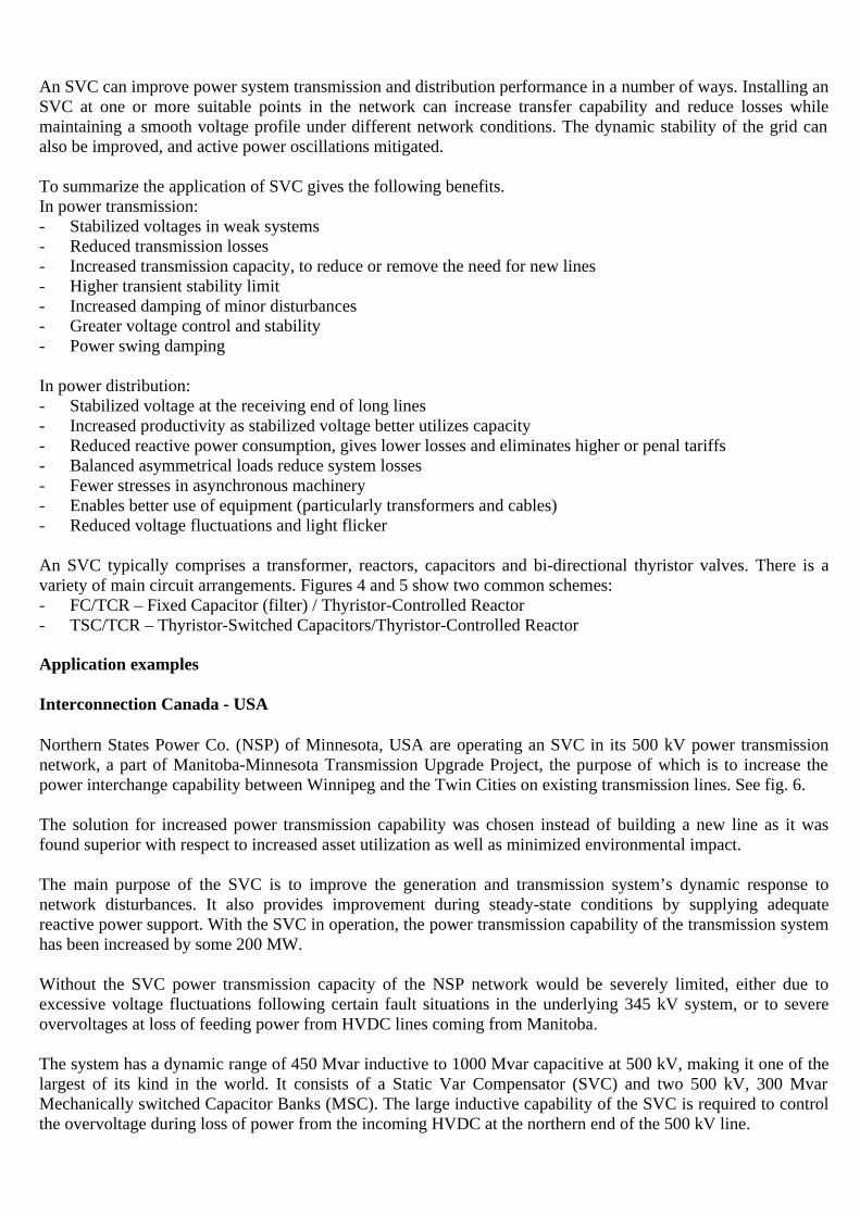
Northern States Power Co. (NSP) of Minnesota, USA are operating an SVC in its 500 kV power transmissionnetwork, a part of Manitoba-Minnesota Transmission Upgrade Project, the purpose of which is to increase thepower interchange capability between Winnipeg and the Twin Cities on existing transmission lines. See fig. 6.
The solution for increased power transmission capability was chosen instead of building a new line as it wasfound superior with respect to increased asset utilization as well as minimized environmental impact.
The main purpose of the SVC is to improve the generation and transmission system’s dynamic response tonetwork disturbances. It also provides improvement during steady-state conditions by supplying adequatereactive power support. With the SVC in operation, the power transmission capability of the transmission systemhas been increased by some 200 MW.
Without the SVC power transmission capacity of the NSP network would be severely limited, either due toexcessive voltage fluctuations following certain fault situations in the underlying 345 kV system, or to severeovervoltages at loss of feeding power from HVDC lines coming from Manitoba.
The system has a dynamic range of 450 Mvar inductive to 1000 Mvar capacitive at 500 kV, making it one of thelargest of its kind in the world. It consists of a Static Var Compensator (SVC) and two 500 kV, 300 MvarMechanically switched Capacitor Banks (MSC). The large inductive capability of the SVC is required to controlthe overvoltage during loss of power from the incoming HVDC at the northern end of the 500 kV line.
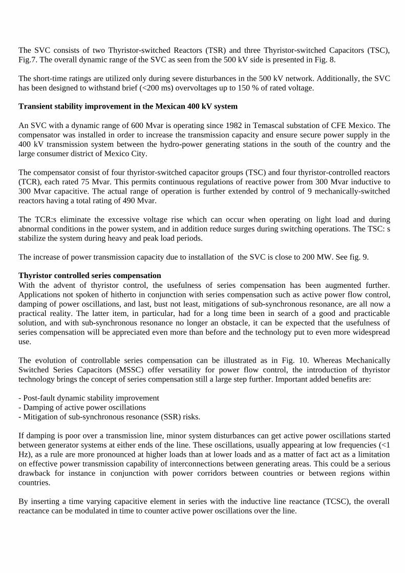
The SVC consists of two Thyristor-switched Reactors (TSR) and three Thyristor-switched Capacitors (TSC),Fig.7. The overall dynamic range of the SVC as seen from the 500 kV side is presented in Fig. 8.
The short-time ratings are utilized only during severe disturbances in the 500 kV network. Additionally, the SVChas been designed to withstand brief (<200 ms) overvoltages up to 150 % of rated voltage.
Transient stability improvement in the Mexican 400 kV system
An SVC with a dynamic range of 600 Mvar is operating since 1982 in Temascal substation of CFE Mexico. Thecompensator was installed in order to increase the transmission capacity and ensure secure power supply in the400 kV transmission system between the hydro-power generating stations in the south of the country and thelarge consumer district of Mexico City.
The compensator consist of four thyristor-switched capacitor groups (TSC) and four thyristor-controlled reactors(TCR), each rated 75 Mvar. This permits continuous regulations of reactive power from 300 Mvar inductive to300 Mvar capacitive. The actual range of operation is further extended by control of 9 mechanically-switchedreactors having a total rating of 490 Mvar.
The TCR:s eliminate the excessive voltage rise which can occur when operating on light load and duringabnormal conditions in the power system, and in addition reduce surges during switching operations. The TSC: sstabilize the system during heavy and peak load periods.
The increase of power transmission capacity due to installation of the SVC is close to 200 MW. See fig. 9.
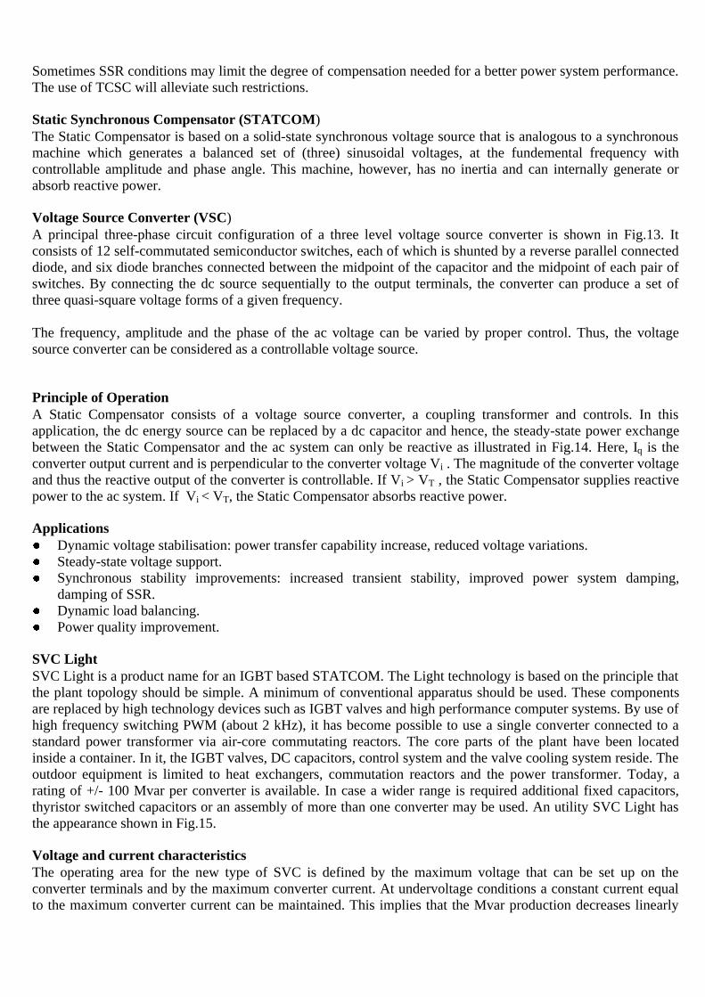
Thyristor controlled series compensationWith the advent of thyristor control, the usefulness of series compensation has been augmented further.Applications not spoken of hitherto in conjunction with series compensation such as active power flow control,damping of power oscillations, and last, bust not least, mitigations of sub-synchronous resonance, are all now apractical reality. The latter item, in particular, had for a long time been in search of a good and practicablesolution, and with sub-synchronous resonance no longer an obstacle, it can be expected that the usefulness ofseries compensation will be appreciated even more than before and the technology put to even more widespreaduse.
The evolution of controllable series compensation can be illustrated as in Fig. 10. Whereas MechanicallySwitched Series Capacitors (MSSC) offer versatility for power flow control, the introduction of thyristortechnology brings the concept of series compensation still a large step further. Important added benefits are:
- Post-fault dynamic stability improvement- Damping of active power oscillations- Mitigation of sub-synchronous resonance (SSR) risks.
If damping is poor over a transmission line, minor system disturbances can get active power oscillations startedbetween generator systems at either ends of the line. These oscillations, usually appearing at low frequencies (<1Hz), as a rule are more pronounced at higher loads than at lower loads and as a matter of fact act as a limitationon effective power transmission capability of interconnections between generating areas. This could be a seriousdrawback for instance in conjunction with power corridors between countries or between regions withincountries.
By inserting a time varying capacitive element in series with the inductive line reactance (TCSC), the overallreactance can be modulated in time to counter active power oscillations over the line.
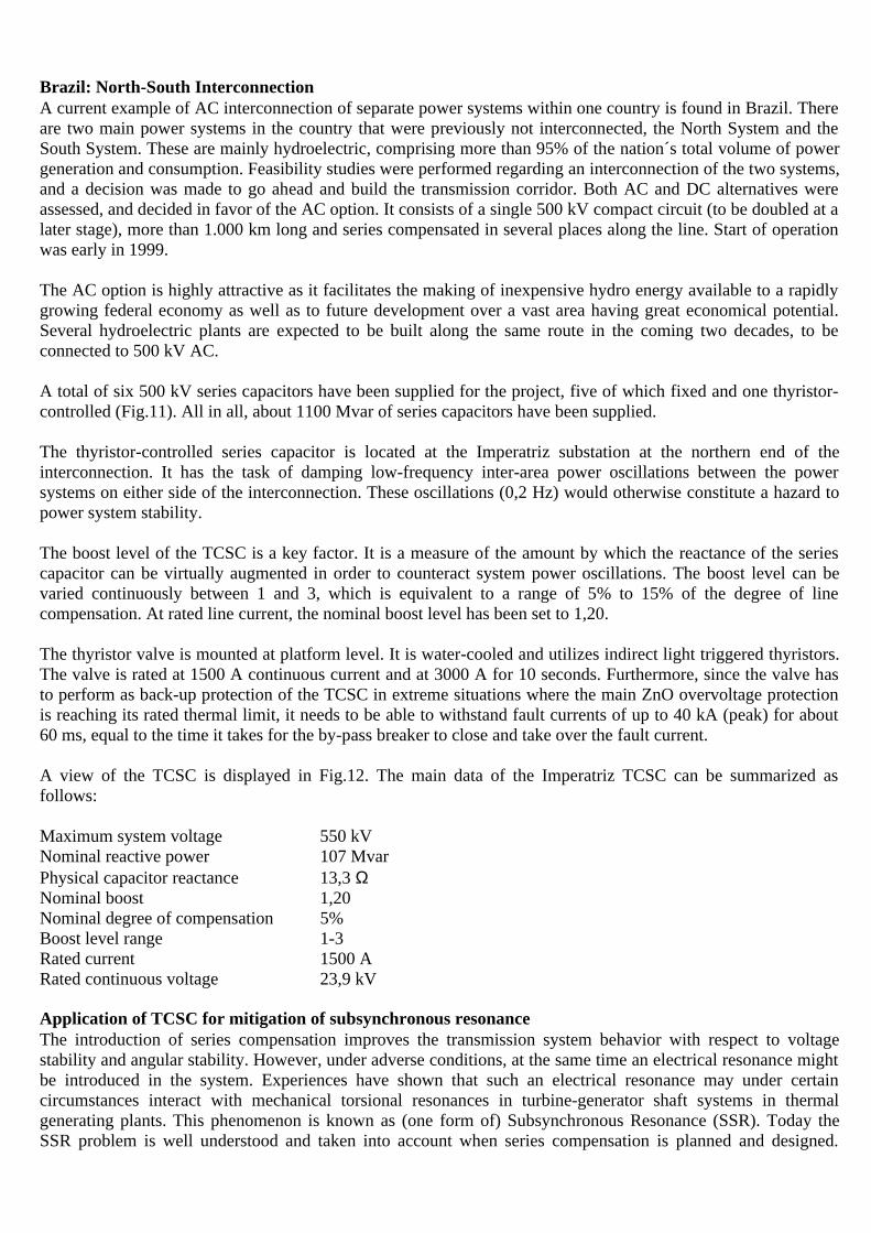
Brazil: North-South InterconnectionA current example of AC interconnection of separate power systems within one country is found in Brazil. Thereare two main power systems in the country that were previously not interconnected, the North System and theSouth System. These are mainly hydroelectric, comprising more than 95% of the nation´s total volume of powergeneration and consumption. Feasibility studies were performed regarding an interconnection of the two systems,and a decision was made to go ahead and build the transmission corridor. Both AC and DC alternatives wereassessed, and decided in favor of the AC option. It consists of a single 500 kV compact circuit (to be doubled at alater stage), more than 1.000 km long and series compensated in several places along the line. Start of operationwas early in 1999.
The AC option is highly attractive as it facilitates the making of inexpensive hydro energy available to a rapidlygrowing federal economy as well as to future development over a vast area having great economical potential.Several hydroelectric plants are expected to be built along the same route in the coming two decades, to beconnected to 500 kV AC.
A total of six 500 kV series capacitors have been supplied for the project, five of which fixed and one thyristor-controlled (Fig.11). All in all, about 1100 Mvar of series capacitors have been supplied.
The thyristor-controlled series capacitor is located at the Imperatriz substation at the northern end of theinterconnection. It has the task of damping low-frequency inter-area power oscillations between the powersystems on either side of the interconnection. These oscillations (0,2 Hz) would otherwise constitute a hazard topower system stability.
The boost level of the TCSC is a key factor. It is a measure of the amount by which the reactance of the seriescapacitor can be virtually augmented in order to counteract system power oscillations. The boost level can bevaried continuously between 1 and 3, which is equivalent to a range of 5% to 15% of the degree of linecompensation. At rated line current, the nominal boost level has been set to 1,20.
The thyristor valve is mounted at platform level. It is water-cooled and utilizes indirect light triggered thyristors.The valve is rated at 1500 A continuous current and at 3000 A for 10 seconds. Furthermore, since the valve hasto perform as back-up protection of the TCSC in extreme situations where the main ZnO overvoltage protectionis reaching its rated thermal limit, it needs to be able to withstand fault currents of up to 40 kA (peak) for about60 ms, equal to the time it takes for the by-pass breaker to close and take over the fault current.
A view of the TCSC is displayed in Fig.12. The main data of the Imperatriz TCSC can be summarized asfollows:
Maximum system voltage 550 kVNominal reactive power 107 MvarPhysical capacitor reactance 13,3 ΩNominal boost 1,20Nominal degree of compensation 5%Boost level range 1-3Rated current 1500 ARated continuous voltage 23,9 kV
Application of TCSC for mitigation of subsynchronous resonanceThe introduction of series compensation improves the transmission system behavior with respect to voltagestability and angular stability. However, under adverse conditions, at the same time an electrical resonance mightbe introduced in the system. Experiences have shown that such an electrical resonance may under certaincircumstances interact with mechanical torsional resonances in turbine-generator shaft systems in thermalgenerating plants. This phenomenon is known as (one form of) Subsynchronous Resonance (SSR). Today theSSR problem is well understood and taken into account when series compensation is planned and designed.
Sometimes SSR conditions may limit the degree of compensation needed for a better power system performance.The use of TCSC will alleviate such restrictions.
Static Synchronous Compensator (STATCOM)The Static Compensator is based on a solid-state synchronous voltage source that is analogous to a synchronousmachine which generates a balanced set of (three) sinusoidal voltages, at the fundemental frequency withcontrollable amplitude and phase angle. This machine, however, has no inertia and can internally generate orabsorb reactive power.
Voltage Source Converter (VSC)A principal three-phase circuit configuration of a three level voltage source converter is shown in Fig.13. Itconsists of 12 self-commutated semiconductor switches, each of which is shunted by a reverse parallel connecteddiode, and six diode branches connected between the midpoint of the capacitor and the midpoint of each pair ofswitches. By connecting the dc source sequentially to the output terminals, the converter can produce a set ofthree quasi-square voltage forms of a given frequency.
The frequency, amplitude and the phase of the ac voltage can be varied by proper control. Thus, the voltagesource converter can be considered as a controllable voltage source.
Principle of OperationA Static Compensator consists of a voltage source converter, a coupling transformer and controls. In thisapplication, the dc energy source can be replaced by a dc capacitor and hence, the steady-state power exchangebetween the Static Compensator and the ac system can only be reactive as illustrated in Fig.14. Here, Iq is theconverter output current and is perpendicular to the converter voltage Vi . The magnitude of the converter voltageand thus the reactive output of the converter is controllable. If Vi > VT , the Static Compensator supplies reactivepower to the ac system. If Vi < VT, the Static Compensator absorbs reactive power.
ApplicationsDynamic voltage stabilisation: power transfer capability increase, reduced voltage variations.Steady-state voltage support.Synchronous stability improvements: increased transient stability, improved power system damping,damping of SSR.Dynamic load balancing.Power quality improvement.
SVC LightSVC Light is a product name for an IGBT based STATCOM. The Light technology is based on the principle thatthe plant topology should be simple. A minimum of conventional apparatus should be used. These componentsare replaced by high technology devices such as IGBT valves and high performance computer systems. By use ofhigh frequency switching PWM (about 2 kHz), it has become possible to use a single converter connected to astandard power transformer via air-core commutating reactors. The core parts of the plant have been locatedinside a container. In it, the IGBT valves, DC capacitors, control system and the valve cooling system reside. Theoutdoor equipment is limited to heat exchangers, commutation reactors and the power transformer. Today, arating of +/- 100 Mvar per converter is available. In case a wider range is required additional fixed capacitors,thyristor switched capacitors or an assembly of more than one converter may be used. An utility SVC Light hasthe appearance shown in Fig.15.
Voltage and current characteristicsThe operating area for the new type of SVC is defined by the maximum voltage that can be set up on theconverter terminals and by the maximum converter current. At undervoltage conditions a constant current equalto the maximum converter current can be maintained. This implies that the Mvar production decreases linearly
with the voltage. During overvoltage conditions the maximum current can be maintained up to the ceiling for theconverter terminal voltage.
Response timeThe semiconductor valves in an SVC Light respond almost instantaneously to a switching order. Therefore thelimiting factor for the comple plant speed of response is determined by the time needed for voltagemeasurements and the control system data processing. A high gain controller can be used and a response timeshorther than a quarter of a cycle is obtained.
Harmonic interaction with the networkThe plant can in most cases be designed completely without harmonic filters. In some cases where therequirements on high order harmonics are very stringent a small highpass link may be necessary. The risk forresonant conditions is therefore negligible. This property makes the SVC Light suitable for easy relocation toother sites at changing network demands.
The high switching frequency used in the SVC Light concept results in an inherent capability to produce voltagesat frequencies well above the fundamental one. This property can be used for active filtering of harmonicsalready present in the network. The SVC Light then injects harmonic currents into the network with proper phaseand amplitude to counteract the harmonic voltages.
Footprint and layoutSVC Light for power utility can be built very compact, see Fig.15. The area required is no more thanapproximately 10 times 20 meters.
HVDC LIGHT for power system interconnections
HVDC Light is a new DC transmission system technology, still consisting of well known components formingthe complete system.
HVDC Light is very suitable for DC power transmission as well as for reactive power generation andconsumption. One HVDC Light unit is capable of transmitting up to about 200 MW, as of today.The same unit can also be used to generate or consume up to about 200 MVAr. These properties are controlledindependently of each other, and this is one of many features with HVDC Light.
As can be seen from the Single Line Diagram, Fig.16, the Converter station consists of only a few components,i.e. the valve bridge and the capacitors on the DC side, the phase reactors and the harmonic filter bank on the ACside. In most applications a three phase step-up transformer is added. One modular housing is including theControl & Protection system, as well as the Station Control and Monitoring system. The valve cooling systemtogether with the auxiliary power system are located in another dedicated module.
HVDC Light is based on the Voltage Source Converter, VSC, technology, where the valves are built by InsulatedGate Bipolar Transistors, IGBT’s. This type of converters are able to switch off the DC current independent ofthe AC voltage. The ± DC voltages are kept constant to an ordered value by high frequency switching of therectifier valves, which thereby charges the DC side capacitors. Furthermore, the VSC inverter can create its ownAC voltage in case of a black AC network, through high frequency switching between the ± DC voltages. This isknown as Pulse Width Modulation, PWM, technique, Fig.17. As mentioned above active and reactive power areseparately controlled. The active power is controlled by adjusting the difference between the phase angles of theAC voltage output from the converter valves and the AC system voltage, measured across the phase reactors.Reactive power is controlled by adjusting the AC voltage amplitude out from the converter valves.
Application areas
Bulk power transmissionThe facility can be used for normal active bulk power transmission with or without imposed modulations, e.g.frequency control.
Reactive power generation/consumptionHVDC Light can be set to consume or generate reactive power, independent of the level of active power, whicheven can be set to zero, still having full reactive power control capability at both ends.
Small scale generationDevelopment of remote small scale generation, such as wind and hydro, will be economically justified, byutilising HVDC Light for transmission of the electricity.
Feeding of local loads, like islandsThe HVDC Light transmission concept makes it feasible, in many cases, to connect remote local loads or islandsto a main grid, thereby enable such loads to benefit from the less costly electricity available from the main grid.
City centre infeedIncreasing the capacity of electricity into city centres by adding new AC over head lines, could be very costly,and in many cases impossible due to the permit requirements. By using the cost effective HVDC Light DC cablesthe energy can be brought into the city centre by underground cables, or connected on existing poles or towers,instead.
Multiterminal DC gridVSC converters are very suitable for creating a DC grid with a large number of converters, since very little co-ordination is needed between the interconnected HVDC Light converters.
Interconnection of asynchronous AC networksDue to the high frequency switching of the IGBT’s, the frequency of the AC networks are of no importance.HVDC Light can handle any frequency up to several hundred of Hz.
Off-shore generationTransmission of electricity derived from excess gas at oil platforms, or from wind mills at sea, becomeseconomically feasible by using HVDC Light for the transmission to the main grid.
Converting existing AC transmission into DCIn areas where permits for building new AC transmission lines are hard or impossible to get, the transmissioncapacity of existing distribution systems can be increased in a very cost effective way, by converting the AClines into HVDC Light DC lines.
Power quality by isolation of disturbing loadsLoads like smelters, normally causes a lot of problems to other loads in the main grid.HVDC Light is very immune to disturbances on the AC systems. This feature makes the VSC converter verysuitable to feed such a disturbing load, thereby isolate the disturbing load from the main grid, preventing otherloads from being damaged.
Advantages with the HVDC Light.- Possible to feed totally islanded and passive AC networks
The VSC converter is able to creates its own AC voltage at any predetermined frequency, without the needfor rotating machines, thanks to the PWM technique.
- Separately control of active and reactive powerActive power transmission and reactive power consumption/generation orders can be set independently ofeach other by the operator. The active power can even be set to zero, while maintaining full reactive powermodulation of the AC systems.
- No contribution to short circuit currentsAt AC system ground faults or short circuits, whereupon the AC voltage drops, the power transmitted by theHVDC is automatically reduced to a predetermined value, hence the contribution to the fault current isdecided by whether the receiving system is isolated or synchronised with the main grid.
- Intercommunication not neededFrom technical point of view, telecommunication between the rectifier and the inverter is not needed, sincethe rectifier keeps the DC voltage constant at the desired value, independent of the power order set at theinverter(s) hooked up to the DC system. The inverter(s) has its own power order, where upon thecorresponding amount of DC current is consumed from the DC side.From convenience point of view for the operators, a telecommunication link might be desired in order tohave the status of the involved converter stations displayed, and to be able to control the entire system fromone location and by one operator or from a dispatch centre.
- Environmental-friendlyCompact design requires a minimum of open space.
- Underground cables instead of OH linesThe visual impact is minimised. No towers or gantries needed for connecting the DC side.
The extruded DC cables can be buried all the way between the converter modules of the stations.
- Short overall delivery timeThe complete system is modularised, standardised, and pretested at the factory, resulting in a minimum ofcommissioning time at site. Furthermore, the site preparation required is fairly simple, due to the low weightof the included modules, forming the converter station.
- RelocateableThe modularised design makes the relocate-ability possible, should the conditions and requirements changein the future.
- Low maintenance requirementsThe only moving parts are the fans and pumps of the valve cooling system.All units are supervised by the redundant MACH 2 control system, from which all necessary informationwill be obtained to ensure safe and reliable operation of the facility.
HVDC Light CablesThe Cables used in HVDC Light applications are a new developed type, where the insulation is made of anextruded polymer that is particularly resistant to DC voltage. Polymeric cables are the preferred choice forHVDC, mainly because of their excellent mechanical strength, flexibility, and low weight.Magnetic fields are eliminated in this facility, which operates in bipolar mode, since the DC current flows inopposite directions in the two cables, the one with a positive voltage and the other with a negative voltage. Thesecables are manufactured both for sea (copper), and land (aluminium) applications.
HVDC Light Converter modules
IGBT valvesThe converter bridge consists of three phases, with two IGBT valves per phase. The corresponding AC phase isconnected between the two valves, which enables the three phases to create a symmetrical DC voltage withopposite polarities, with respect to the midpoint grounded DC capacitors.Each valve consists of a number of IGBT’s, determined by the DC voltage level, which in turn is directlyproportional to the DC power level. The IGBT’s are switched on and off with a constant frequency of about 2kHz.
Phase reactorsThese are standard single phase air cooled reactors. They are used for controlling both the active and the reactivepower flow, as well as for smoothing of the current, and reducing the inrush currents upon energization from theAC side. The reactors are essential for both the active and reactive power flow, since these properties aredetermined by the power frequency voltage across the reactors.
DC side capacitorsOn the DC side there are two capacitor stacks of the same size, one from each one of the poles to ground. Thesize of these capacitors are depending on the required DC voltage.The purpose is to keep a stable DC voltage at the desired level. The capacitors stacks are being charged toopposite polarities by the high frequency switching IGBT’s.
AC filtersThe AC voltage output contains harmonic components, derived from the switching of the IGBT’s.These harmonics have to be taken care off, preventing them from being emitted into the AC system or the air,causing malfunctioning of AC system equipment or radio and telecommunication disturbances.One single HP filter branch is enough to take care off these low energy harmonics.
Fig. 1: 400 kV SC - Swedish National Grid
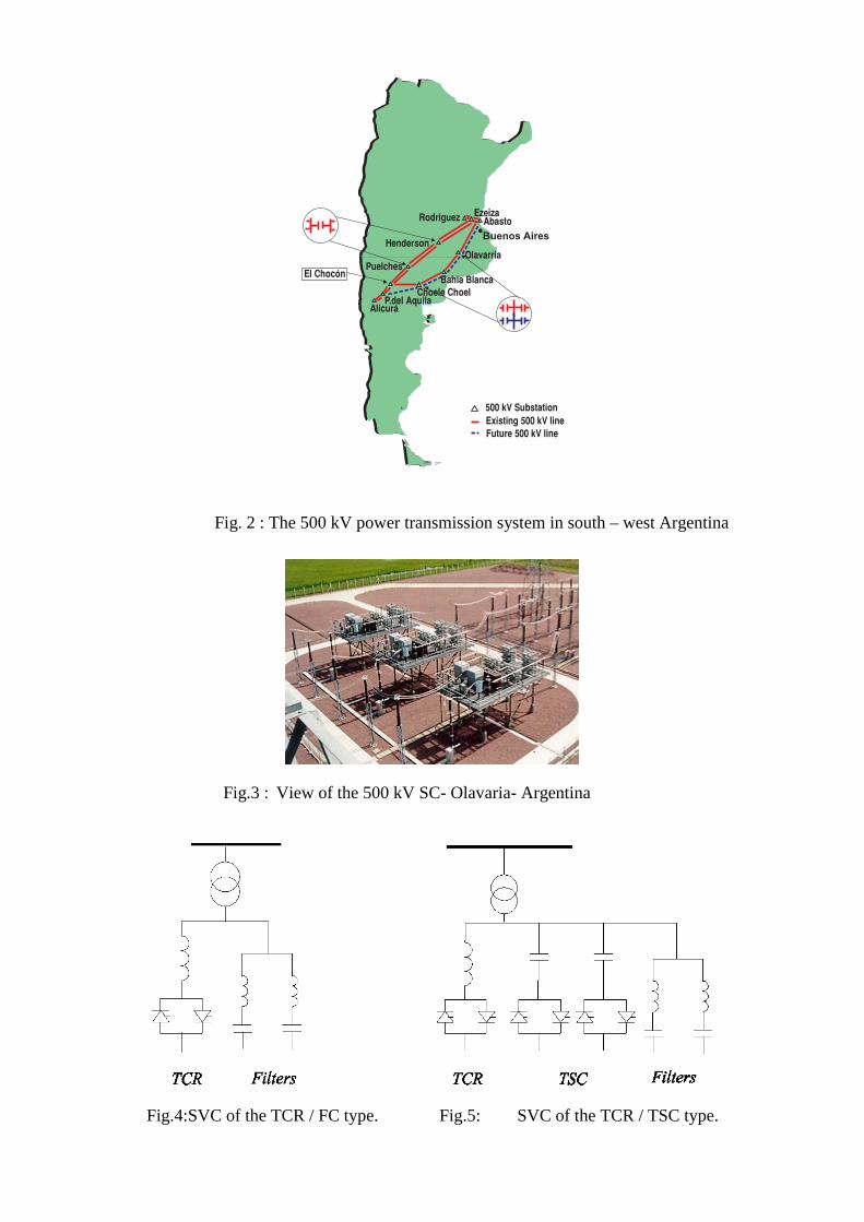
Fig. 2 : The 500 kV power transmission system in south – west Argentina
Fig.3 : View of the 500 kV SC- Olavaria- Argentina
Fig.4:SVC of the TCR / FC type. Fig.5: SVC of the TCR / TSC type.
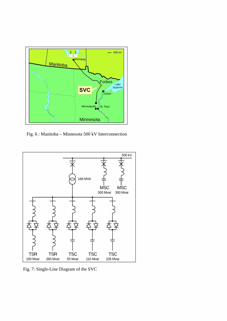
Fig. 6 : Manitoba – Minnesota 500 kV Interconnection
Fig. 7: Single-Line Diagram of the SVC
Minnesota
Forbes
Manitoba
LakeSuperior
Duluth
Minneapolis
Winnipeg
St. Paul
500 kV
69&
500 kV
168 MVA
TSR260 Mvar
TSC55 Mvar
TSC110 Mvar
MSC300 Mvar
MSC300 Mvar
TSC235 Mvar
TSR190 Mvar
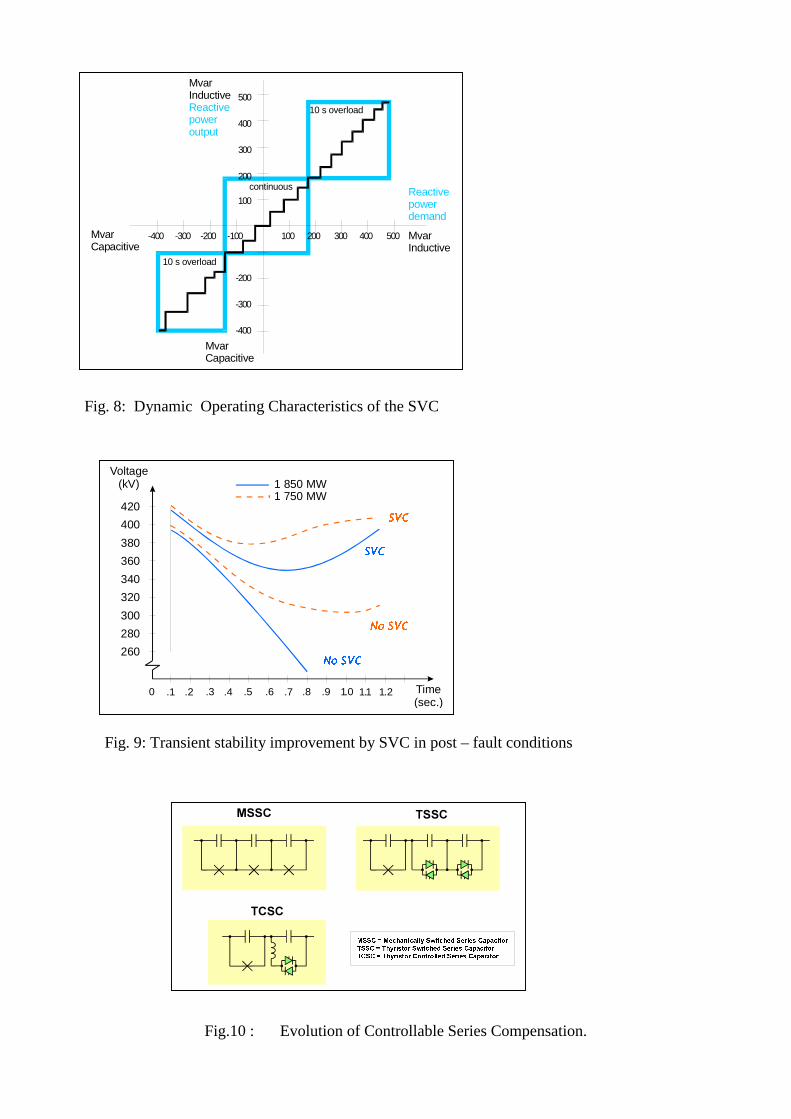
Fig. 8: Dynamic Operating Characteristics of the SVC
Fig. 9: Transient stability improvement by SVC in post – fault conditions
Fig.10 : Evolution of Controllable Series Compensation.
300
400
500
-400 -300 400 500
MvarInductiveReactive poweroutput
Reactive powerdemand
MvarInductive
MvarCapacitive
10 s overload
continuous
10 s overload
MvarCapacitive
-400
-300
-200
100 200 300-200 -100
200
100
Voltage(kV)
Time(sec.)
1 850 MW1 750 MW
1R69&
1R69&
69&
69&
260
0 .1 .2 .3 .4 .5 .6 .7 .8 .9 1.0 1.1 1.2
280
300
320
340
360
380
400
420
066& 766&
7&6&
066& 0HFKDQLFDOO\6ZLWFKHG6HULHV&DSDFLWRU
766& 7K\ULVWRU6ZLWFKHG6HULHV&DSDFLWRU
7&6& 7K\ULVWRU&RQWUROOHG6HULHV&DSDFLWRU
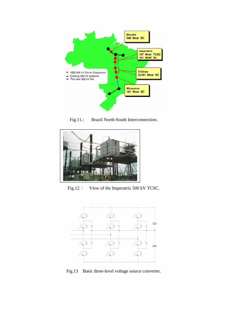
Fig.11.: Brazil North-South Interconnection.
Fig.12 : View of the Imperatriz 500 kV TCSC.
Fig.13 Basic three-level voltage source converter.

.
Fig.14 : Static Compensator.
Fig.15 : Typical SVC Light for utility applications.
Figure 16 .Shows the main equipment of a typical transmission
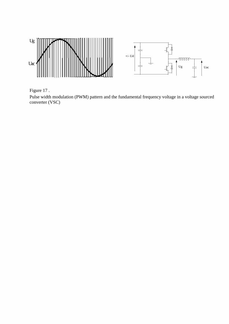
Figure 17 .
Pulse width modulation (PWM) pattern and the fundamental frequency voltage in a voltage sourcedconverter (VSC)
Ug
Uac
+/- Ud
UacUg