Embed Size (px)
Citation preview
0885-8993 (c) 2019 IEEE. Personal use is permitted, but republication/redistribution requires IEEE permission. See http://www.ieee.org/publications_standards/publications/rights/index.html for more information.
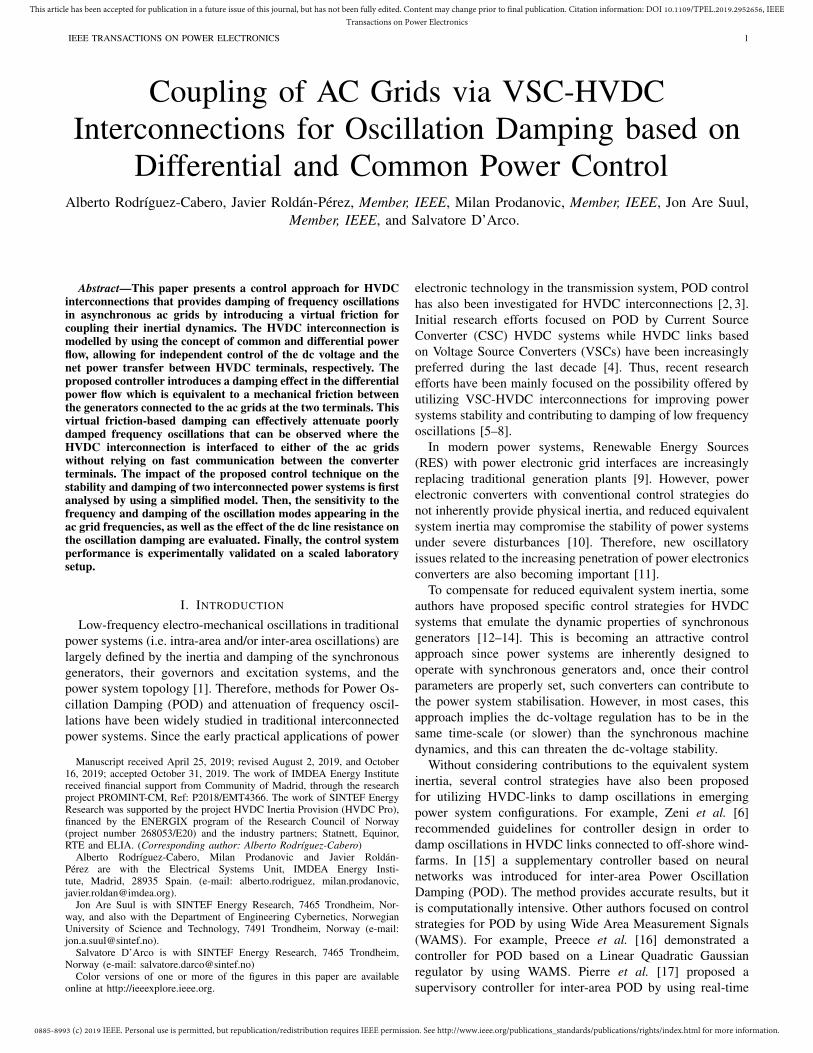
This article has been accepted for publication in a future issue of this journal, but has not been fully edited. Content may change prior to final publication. Citation information: DOI 10.1109/TPEL.2019.2952656, IEEETransactions on Power Electronics
IEEE TRANSACTIONS ON POWER ELECTRONICS 1
Coupling of AC Grids via VSC-HVDCInterconnections for Oscillation Damping based on
Differential and Common Power ControlAlberto Rodrıguez-Cabero, Javier Roldan-Perez, Member, IEEE, Milan Prodanovic, Member, IEEE, Jon Are Suul,
Member, IEEE, and Salvatore D’Arco.
Abstract—This paper presents a control approach for HVDCinterconnections that provides damping of frequency oscillationsin asynchronous ac grids by introducing a virtual friction forcoupling their inertial dynamics. The HVDC interconnection ismodelled by using the concept of common and differential powerflow, allowing for independent control of the dc voltage and thenet power transfer between HVDC terminals, respectively. Theproposed controller introduces a damping effect in the differentialpower flow which is equivalent to a mechanical friction betweenthe generators connected to the ac grids at the two terminals. Thisvirtual friction-based damping can effectively attenuate poorlydamped frequency oscillations that can be observed where theHVDC interconnection is interfaced to either of the ac gridswithout relying on fast communication between the converterterminals. The impact of the proposed control technique on thestability and damping of two interconnected power systems is firstanalysed by using a simplified model. Then, the sensitivity to thefrequency and damping of the oscillation modes appearing in theac grid frequencies, as well as the effect of the dc line resistance onthe oscillation damping are evaluated. Finally, the control systemperformance is experimentally validated on a scaled laboratorysetup.
I. INTRODUCTION
Low-frequency electro-mechanical oscillations in traditionalpower systems (i.e. intra-area and/or inter-area oscillations) arelargely defined by the inertia and damping of the synchronousgenerators, their governors and excitation systems, and thepower system topology [1]. Therefore, methods for Power Os-cillation Damping (POD) and attenuation of frequency oscil-lations have been widely studied in traditional interconnectedpower systems. Since the early practical applications of power
Manuscript received April 25, 2019; revised August 2, 2019, and October16, 2019; accepted October 31, 2019. The work of IMDEA Energy Institutereceived financial support from Community of Madrid, through the researchproject PROMINT-CM, Ref: P2018/EMT4366. The work of SINTEF EnergyResearch was supported by the project HVDC Inertia Provision (HVDC Pro),financed by the ENERGIX program of the Research Council of Norway(project number 268053/E20) and the industry partners; Statnett, Equinor,RTE and ELIA. (Corresponding author: Alberto Rodrıguez-Cabero)
Alberto Rodrıguez-Cabero, Milan Prodanovic and Javier Roldan-Perez are with the Electrical Systems Unit, IMDEA Energy Insti-tute, Madrid, 28935 Spain. (e-mail: alberto.rodriguez, milan.prodanovic,[email protected]).
Jon Are Suul is with SINTEF Energy Research, 7465 Trondheim, Nor-way, and also with the Department of Engineering Cybernetics, NorwegianUniversity of Science and Technology, 7491 Trondheim, Norway (e-mail:[email protected]).
Salvatore D’Arco is with SINTEF Energy Research, 7465 Trondheim,Norway (e-mail: [email protected])
Color versions of one or more of the figures in this paper are availableonline at http://ieeexplore.ieee.org.
electronic technology in the transmission system, POD controlhas also been investigated for HVDC interconnections [2, 3].Initial research efforts focused on POD by Current SourceConverter (CSC) HVDC systems while HVDC links basedon Voltage Source Converters (VSCs) have been increasinglypreferred during the last decade [4]. Thus, recent researchefforts have been mainly focused on the possibility offered byutilizing VSC-HVDC interconnections for improving powersystems stability and contributing to damping of low frequencyoscillations [5–8].
In modern power systems, Renewable Energy Sources(RES) with power electronic grid interfaces are increasinglyreplacing traditional generation plants [9]. However, powerelectronic converters with conventional control strategies donot inherently provide physical inertia, and reduced equivalentsystem inertia may compromise the stability of power systemsunder severe disturbances [10]. Therefore, new oscillatoryissues related to the increasing penetration of power electronicsconverters are also becoming important [11].
To compensate for reduced equivalent system inertia, someauthors have proposed specific control strategies for HVDCsystems that emulate the dynamic properties of synchronousgenerators [12–14]. This is becoming an attractive controlapproach since power systems are inherently designed tooperate with synchronous generators and, once their controlparameters are properly set, such converters can contribute tothe power system stabilisation. However, in most cases, thisapproach implies the dc-voltage regulation has to be in thesame time-scale (or slower) than the synchronous machinedynamics, and this can threaten the dc-voltage stability.
Without considering contributions to the equivalent systeminertia, several control strategies have also been proposedfor utilizing HVDC-links to damp oscillations in emergingpower system configurations. For example, Zeni et al. [6]recommended guidelines for controller design in order todamp oscillations in HVDC links connected to off-shore wind-farms. In [15] a supplementary controller based on neuralnetworks was introduced for inter-area Power OscillationDamping (POD). The method provides accurate results, but itis computationally intensive. Other authors focused on controlstrategies for POD by using Wide Area Measurement Signals(WAMS). For example, Preece et al. [16] demonstrated acontroller for POD based on a Linear Quadratic Gaussianregulator by using WAMS. Pierre et al. [17] proposed asupervisory controller for inter-area POD by using real-time
0885-8993 (c) 2019 IEEE. Personal use is permitted, but republication/redistribution requires IEEE permission. See http://www.ieee.org/publications_standards/publications/rights/index.html for more information.
This article has been accepted for publication in a future issue of this journal, but has not been fully edited. Content may change prior to final publication. Citation information: DOI 10.1109/TPEL.2019.2952656, IEEETransactions on Power Electronics
IEEE TRANSACTIONS ON POWER ELECTRONICS 2
Cdc1
v 2
vpcc2
Network 2
Frequency
VSC1 VSC2L L
G2
Virtual friction
s
controller
Cf
OI
Δ*1Q* P
Cdc2i 1 L L
Cf
O I
Generator controller
vpcc1
Network 1
G1
Generator controller
v 1si 1
vdc1
1 vdc* 2*
controller
Δ*Q* P vdc**2
p1O*
Virtual frictionestimator
VSCcontroller
O
O
vpcc1
i 2O
Frequencyestimator
i 2O
2
p2O*
VSCcontroller
vpcc2
vdc
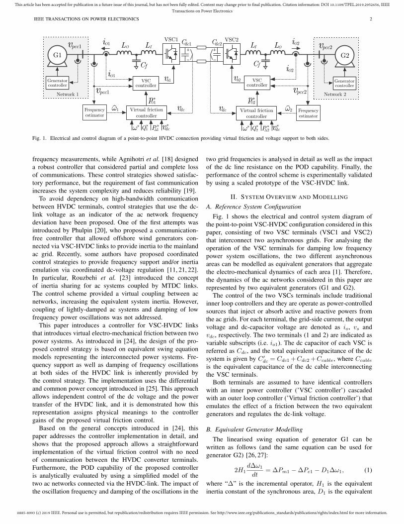
Fig. 1. Electrical and control diagram of a point-to-point HVDC connection providing virtual friction and voltage support to both sides.
frequency measurements, while Agnihotri et al. [18] designeda robust controller that considered partial and complete lossof communications. These control strategies showed satisfac-tory performance, but the requirement of fast communicationincreases the system complexity and reduces reliability [19].
To avoid dependency on high-bandwidth communicationbetween HVDC terminals, control strategies that use the dc-link voltage as an indicator of the ac network frequencydeviation have been proposed. One of the first attempts wasintroduced by Phulpin [20], who proposed a communication-free controller that allowed offshore wind generators con-nected via VSC-HVDC links to provide inertia to the mainlandac grid. Recently, some authors have proposed coordinatedcontrol strategies to provide frequency support and/or inertiaemulation via coordinated dc-voltage regulation [11, 21, 22].In particular, Rouzbehi et al. [23] introduced the conceptof inertia sharing for ac systems coupled by MTDC links.The control scheme provided a virtual coupling between acnetworks, increasing the equivalent system inertia. However,coupling of lightly-damped ac systems and damping of lowfrequency power oscillations was not addressed.
This paper introduces a controller for VSC-HVDC linksthat introduces virtual electro-mechanical friction between twopower systems. As introduced in [24], the design of the pro-posed control strategy is based on equivalent swing equationmodels representing the interconnected power systems. Fre-quency support as well as damping of frequency oscillationsat both sides of the HVDC link is inherently provided bythe control strategy. The implementation uses the differentialand common power concept introduced in [25]. This approachallows independent control of the dc voltage and the powertransfer of the HVDC link, and it is demonstrated how thisrepresentation assigns physical meanings to the controllergains of the proposed virtual friction control.
Based on the general concepts introduced in [24], thispaper addresses the controller implementation in detail, andshows that the proposed approach allows a straightforwardimplementation of the virtual friction control with no needof communication between the HVDC converter terminals.Furthermore, the POD capability of the proposed controlleris analytically evaluated by using a simplified model of thetwo ac networks connected via the HVDC-link. The impact ofthe oscillation frequency and damping of the oscillations in the
two grid frequencies is analysed in detail as well as the impactof the dc line resistance on the POD capability. Finally, theperformance of the control scheme is experimentally validatedby using a scaled prototype of the VSC-HVDC link.
II. SYSTEM OVERVIEW AND MODELLING
A. Reference System ConfigurationFig. 1 shows the electrical and control system diagram of
the point-to-point VSC-HVDC configuration considered in thispaper, consisting of two VSC terminals (VSC1 and VSC2)that interconnect two asynchronous grids. For analysing theoperation of the VSC terminals for damping low frequencypower system oscillations, the two different asynchronousareas can be modelled as equivalent generators that aggregatethe electro-mechanical dynamics of each area [1]. Therefore,the dynamics of the ac networks considered in this paper arerepresented by two equivalent generators (G1 and G2).
The control of the two VSCs terminals include traditionalinner loop controllers and they are operate as power-controlledsources that inject or absorb active and reactive powers fromthe ac grids. For each terminal, the grid-side current, the outputvoltage and dc-capacitor voltage are denoted as io, vs andvdc, respectively. The two terminals (1 and 2) are indicated asvariable subscripts (i.e. io1). The dc capacitor of each VSC isreferred as Cdc, and the total equivalent capacitance of the dcsystem is given by C ′dc = Cdc1 +Cdc2 +Ccable, where Ccable
is the equivalent capacitance of the dc cable interconnectingthe VSC terminals.
Both terminals are assumed to have identical controllerswith an inner power controller (’VSC controller’) cascadedwith an outer loop controller (’Virtual friction controller’) thatemulates the effect of a friction between the two equivalentgenerators and regulates the dc-link voltage.
B. Equivalent Generator ModellingThe linearised swing equation of generator G1 can be
written as follows (and the same equation can be used forgenerator G2) [26, 27]:
2H1d∆ω1
dt= ∆Pm1 −∆Pe1 −D1∆ω1, (1)
where “∆” is the incremental operator, H1 is the equivalentinertia constant of the synchronous area, D1 is the equivalent
0885-8993 (c) 2019 IEEE. Personal use is permitted, but republication/redistribution requires IEEE permission. See http://www.ieee.org/publications_standards/publications/rights/index.html for more information.
This article has been accepted for publication in a future issue of this journal, but has not been fully edited. Content may change prior to final publication. Citation information: DOI 10.1109/TPEL.2019.2952656, IEEETransactions on Power Electronics
IEEE TRANSACTIONS ON POWER ELECTRONICS 3
VSC1 VSC2
pcmpΔ
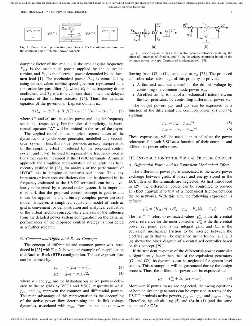
Fig. 2. Power flow representation in a Back to Back configuration based onthe common and differential power concepts.
damping factor of the area, ω1 is the area angular frequency,Pm1 is the mechanical power supplied by the equivalentturbine, and Pe1 is the electrical power demanded by the localarea load [1]. The mechanical power Pm1 is controlled byusing an equivalent turbine speed governor represented as afirst-order low-pass-filter [1], where R1 is the frequency droopcoefficient, and T1 is a time constant that models the delayedresponse of the turbine actuator [26]. Thus, the dynamicequation of the governor in Laplace domain is:
∆Pm1 = ∆P ∗ +R1/(T1s+ 1) · (∆ω∗ −∆ω1), (2)
where P ∗ and ω∗ are the active power and angular frequencyset points, respectively. For the sake of simplicity, the incre-mental operator “∆” will be omitted in the rest of the paper.
The applied model is the simplest representation of thedynamics of a synchronous generator, modelled as a second-order system. Thus, this model provides an easy interpretationof the coupling effect introduced by the proposed controlsystem and it will be used to represent the frequency oscilla-tions that can be measured at the HVDC terminals. A similarapproach for simplified representation of ac grids has beenrecently justified in [28], for analysis of the performance ofHVDC links in damping of inter-area oscillations. Thus, anyintra-area or inter-area oscillations that can be detected in thefrequency estimated at the HVDC terminals can be equiva-lently represented by a second-order system. It is importantto remark that the proposed control concept is generic andit can be applied in any arbitrary complex power networkmodel. However, a simplified equivalent model of each acgrid is convenient for demonstration and analytical evaluationof the virtual friction concept, while analysis of the influencefrom the detailed power system configuration on the dynamicperformances of the proposed control strategy is consideredas a further research.
C. Common and Differential Power Concepts
The concept of differential and common power was intro-duced in [25] with Fig. 2 showing an example of its applicationto a Back-to-Back (BTB) configuration. The active power flowcan be defined by:
pcm = −(po1 + po2), (3)p∆ = (po1 − po2)/2, (4)
where po1 and po2 are the instantaneous active powers deliv-ered to the ac grids by VSC1 and VSC2, respectively whilepcm and p∆ represent the common and differential powers.The main advantage of this representation is the decouplingof the active power flow determining the dc link voltagedynamics, associated with pcm, from the net active power
vdc*2
vdc2
pcm
pΔ
p
P
B
*
*
Δ
Δ
sK�
�2
1�
*
sKidc
Kpdc
(a) (b)
Fig. 3. Block diagram of (a) a differential power controller emulating theeffect of a mechanical friction, and (b) the dc-voltage controller based on thecommon power concept. Centralised implementation [29].
flowing from G2 to G1, associated to p∆ [25]. The proposedcontroller takes advantage of this property to provide:• A fast and accurate control of the dc-link voltage by
controlling the common-mode power pcm.• An effect similar to that of a mechanical friction between
the two generators by controlling differential power p∆.The output powers po1 and po2 can be expressed as a
function of the differential and common power, (3) and (4),yielding:
po1 = p∆ − pcm/2, (5)po2 = −p∆ − pcm/2. (6)
These expressions will be used later to calculate the powerreferences for each VSC as a function of their common anddifferential power references.
III. INTRODUCTION TO THE VIRTUAL FRICTION CONCEPT
A. Differential Power and its Equivalent Mechanical Effect
The differential power p∆ is associated to the active powerexchange between grids, if losses and energy stored in theLCL filters of the terminals are neglected. As first introducedin [29], the differential power can be controlled to providean effect equivalent to that of a mechanical friction betweenthe ac networks. With this aim, the following expression isdefined:
p∗∆ = (K∆/s) · (P ∗∆ − p∆ +Bω(ω1 − ω2)). (7)
The hat “ ˆ ” refers to estimated values, p∗∆ is the differentialpower reference for the inner controller, P ∗∆ is the differentialpower set point, K∆ is the integral gain, and Bω is theequivalent mechanical friction to be inserted between theelectrical grids that will be explained in the following. Fig. 3(a) shows the block diagram of a centralised controller basedon this concept [29].
If the transient response of the differential-power controlleris significantly faster than that of the equivalent generators(G1 and G2), its dynamics can be neglected for system-levelstudies. This assumption will be guaranteed during the designprocess. Thus, the differential power can be expressed as:
p∆ = P ∗∆ +Bω(ω1 − ω2). (8)
Moreover, if power losses are neglected, the swing equationsof both equivalent generators can be expressed in terms of theHVDC terminals active powers, pe1 = −po1 and pe2 = −po2.Therefore, by substituting (5) and (6) in (1) (and the sameequation for G2):
0885-8993 (c) 2019 IEEE. Personal use is permitted, but republication/redistribution requires IEEE permission. See http://www.ieee.org/publications_standards/publications/rights/index.html for more information.
This article has been accepted for publication in a future issue of this journal, but has not been fully edited. Content may change prior to final publication. Citation information: DOI 10.1109/TPEL.2019.2952656, IEEETransactions on Power Electronics
IEEE TRANSACTIONS ON POWER ELECTRONICS 4
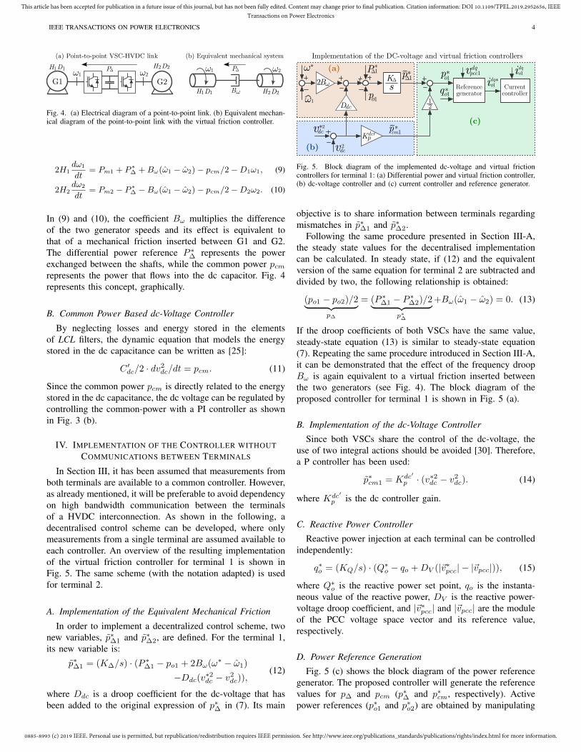
(a) Point-to-point VSC-HVDC link
G1
1
(b) Equivalent mechanical system
2
BD1H1 D2H2
D1H1 D2H2
1
G22
PΔ PΔ
Fig. 4. (a) Electrical diagram of a point-to-point link. (b) Equivalent mechan-ical diagram of the point-to-point link with the virtual friction controller.
2H1dω1
dt= Pm1 + P ∗
∆ +Bω(ω1 − ω2)− pcm/2−D1ω1, (9)
2H2dω2
dt= Pm2 − P ∗
∆ −Bω(ω1 − ω2)− pcm/2−D2ω2. (10)
In (9) and (10), the coefficient Bω multiplies the differenceof the two generator speeds and its effect is equivalent tothat of a mechanical friction inserted between G1 and G2.The differential power reference P ∗∆ represents the powerexchanged between the shafts, while the common power pcmrepresents the power that flows into the dc capacitor. Fig. 4represents this concept, graphically.
B. Common Power Based dc-Voltage Controller
By neglecting losses and energy stored in the elementsof LCL filters, the dynamic equation that models the energystored in the dc capacitance can be written as [25]:
C ′dc/2 · dv2dc/dt = pcm. (11)
Since the common power pcm is directly related to the energystored in the dc capacitance, the dc voltage can be regulated bycontrolling the common-power with a PI controller as shownin Fig. 3 (b).
IV. IMPLEMENTATION OF THE CONTROLLER WITHOUTCOMMUNICATIONS BETWEEN TERMINALS
In Section III, it has been assumed that measurements fromboth terminals are available to a common controller. However,as already mentioned, it will be preferable to avoid dependencyon high bandwidth communication between the terminalsof a HVDC interconnection. As shown in the following, adecentralised control scheme can be developed, where onlymeasurements from a single terminal are assumed available toeach controller. An overview of the resulting implementationof the virtual friction controller for terminal 1 is shown inFig. 5. The same scheme (with the notation adapted) is usedfor terminal 2.
A. Implementation of the Equivalent Mechanical Friction
In order to implement a decentralized control scheme, twonew variables, p∗∆1 and p∗∆2, are defined. For the terminal 1,its new variable is:
p∗∆1 = (K∆/s) · (P ∗∆1 − po1 + 2Bω(ω∗ − ω1)
−Ddc(v∗2dc − v2
dc)),(12)
where Ddc is a droop coefficient for the dc-voltage that hasbeen added to the original expression of p∗∆ in (7). Its main
idq*p
Referencegeneratorq*
vpcc1dq
vdc*2
vdc2
pcm
pΔ
p
P
B
*
*
*Δ
sKΔ
1
Kp
Ddc
Currentcontroller
12
o1o1
o1
*1
1
Implementation of the DC-voltage and virtual friction controllers
idqo1
dc
o1
*~1
'~
(a)
(b)
(c)
2
Fig. 5. Block diagram of the implemented dc-voltage and virtual frictioncontrollers for terminal 1: (a) Differential power and virtual friction controller,(b) dc-voltage controller and (c) current controller and reference generator.
objective is to share information between terminals regardingmismatches in p∗∆1 and p∗∆2.
Following the same procedure presented in Section III-A,the steady state values for the decentralised implementationcan be calculated. In steady state, if (12) and the equivalentversion of the same equation for terminal 2 are subtracted anddivided by two, the following relationship is obtained:
(po1 − po2)/2︸ ︷︷ ︸p∆
= (P ∗∆1 − P ∗∆2)/2︸ ︷︷ ︸p∗∆
+Bω(ω1 − ω2) = 0. (13)
If the droop coefficients of both VSCs have the same value,steady-state equation (13) is similar to steady-state equation(7). Repeating the same procedure introduced in Section III-A,it can be demonstrated that the effect of the frequency droopBω is again equivalent to a virtual friction inserted betweenthe two generators (see Fig. 4). The block diagram of theproposed controller for terminal 1 is shown in Fig. 5 (a).
B. Implementation of the dc-Voltage Controller
Since both VSCs share the control of the dc-voltage, theuse of two integral actions should be avoided [30]. Therefore,a P controller has been used:
p∗cm1 = Kdc′
p · (v∗2dc − v2dc). (14)
where Kdc′
p is the dc controller gain.
C. Reactive Power Controller
Reactive power injection at each terminal can be controlledindependently:
q∗o = (KQ/s) · (Q∗o − qo +DV (|~v∗pcc| − |~vpcc|)), (15)
where Q∗o is the reactive power set point, qo is the instanta-neous value of the reactive power, DV is the reactive power-voltage droop coefficient, and |~v∗pcc| and |~vpcc| are the moduleof the PCC voltage space vector and its reference value,respectively.
D. Power Reference Generation
Fig. 5 (c) shows the block diagram of the power referencegenerator. The proposed controller will generate the referencevalues for p∆ and pcm (p∗∆ and p∗cm, respectively). Activepower references (p∗o1 and p∗o2) are obtained by manipulating
0885-8993 (c) 2019 IEEE. Personal use is permitted, but republication/redistribution requires IEEE permission. See http://www.ieee.org/publications_standards/publications/rights/index.html for more information.
This article has been accepted for publication in a future issue of this journal, but has not been fully edited. Content may change prior to final publication. Citation information: DOI 10.1109/TPEL.2019.2952656, IEEETransactions on Power Electronics
IEEE TRANSACTIONS ON POWER ELECTRONICS 5
sH2
1
+D2
2
pm
Pe2
2
sT2 +1
R2 *
2
2sCdc
PΔ*po2
s +K
K
*
vdc2*
1 Pe1
pm1
sT1 +1
R1*
sH1
1+D12
B
PΔ* p
o1
s +K
K
*
2
vdc2
1
dcD s+KdcpK2 dcD s+
KdcpK2
Generator 1
1 2
Frequency
estimator
Frequency
estimator
Generator 2
vdc2*
2 B2
'DC voltage
loop
DC voltage
loop
Virtual
friction
loop
Virtual
friction
loop
pcmΔ
Δ
Δ
Δ
Δ Δ
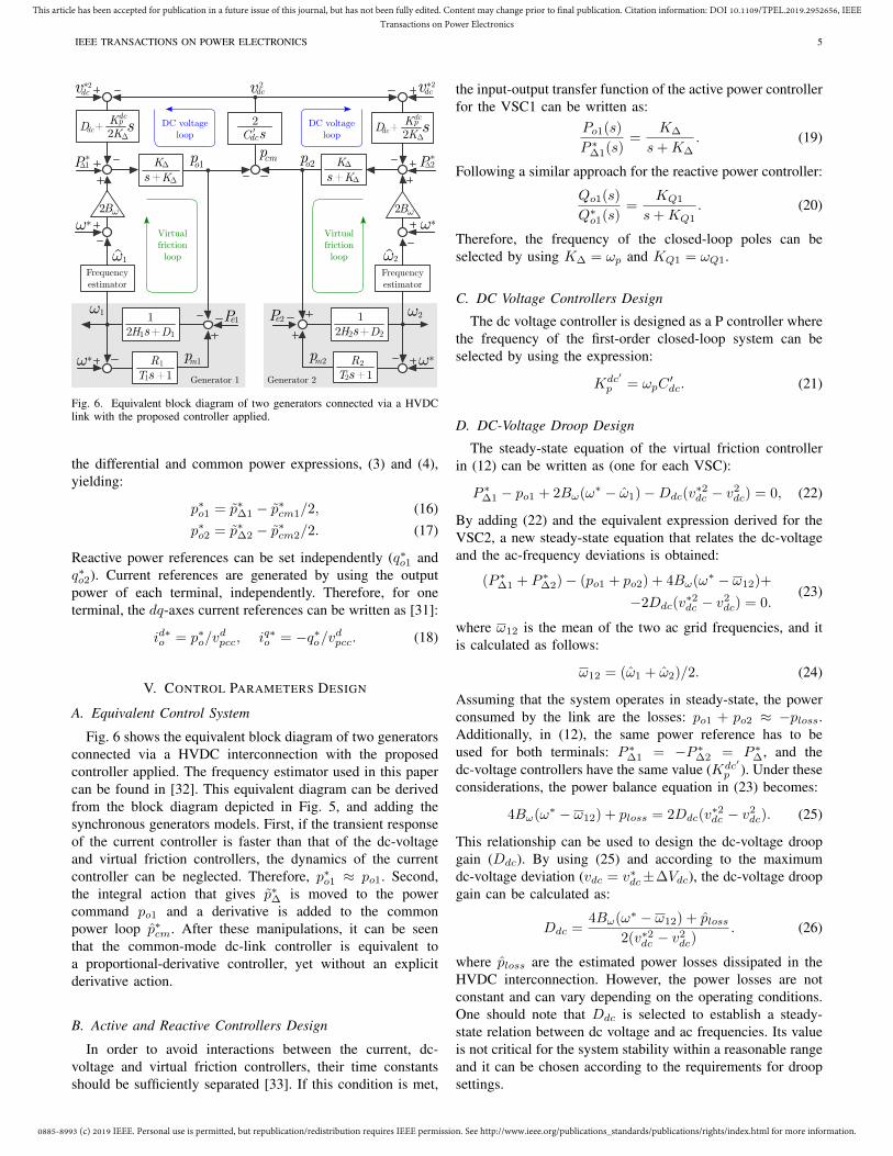
Fig. 6. Equivalent block diagram of two generators connected via a HVDClink with the proposed controller applied.
the differential and common power expressions, (3) and (4),yielding:
p∗o1 = p∗∆1 − p∗cm1/2, (16)p∗o2 = p∗∆2 − p∗cm2/2. (17)
Reactive power references can be set independently (q∗o1 andq∗o2). Current references are generated by using the outputpower of each terminal, independently. Therefore, for oneterminal, the dq-axes current references can be written as [31]:
id∗o = p∗o/vdpcc, iq∗o = −q∗o/vdpcc. (18)
V. CONTROL PARAMETERS DESIGN
A. Equivalent Control System
Fig. 6 shows the equivalent block diagram of two generatorsconnected via a HVDC interconnection with the proposedcontroller applied. The frequency estimator used in this papercan be found in [32]. This equivalent diagram can be derivedfrom the block diagram depicted in Fig. 5, and adding thesynchronous generators models. First, if the transient responseof the current controller is faster than that of the dc-voltageand virtual friction controllers, the dynamics of the currentcontroller can be neglected. Therefore, p∗o1 ≈ po1. Second,the integral action that gives p∗∆ is moved to the powercommand po1 and a derivative is added to the commonpower loop p∗cm. After these manipulations, it can be seenthat the common-mode dc-link controller is equivalent toa proportional-derivative controller, yet without an explicitderivative action.
B. Active and Reactive Controllers Design
In order to avoid interactions between the current, dc-voltage and virtual friction controllers, their time constantsshould be sufficiently separated [33]. If this condition is met,
the input-output transfer function of the active power controllerfor the VSC1 can be written as:
Po1(s)
P ∗∆1(s)=
K∆
s+K∆. (19)
Following a similar approach for the reactive power controller:
Qo1(s)
Q∗o1(s)=
KQ1
s+KQ1. (20)
Therefore, the frequency of the closed-loop poles can beselected by using K∆ = ωp and KQ1 = ωQ1.
C. DC Voltage Controllers Design
The dc voltage controller is designed as a P controller wherethe frequency of the first-order closed-loop system can beselected by using the expression:
Kdc′
p = ωpC′dc. (21)
D. DC-Voltage Droop Design
The steady-state equation of the virtual friction controllerin (12) can be written as (one for each VSC):
P ∗∆1 − po1 + 2Bω(ω∗ − ω1)−Ddc(v∗2dc − v2
dc) = 0, (22)
By adding (22) and the equivalent expression derived for theVSC2, a new steady-state equation that relates the dc-voltageand the ac-frequency deviations is obtained:
(P ∗∆1 + P ∗∆2)− (po1 + po2) + 4Bω(ω∗ − ω12)+
−2Ddc(v∗2dc − v2
dc) = 0.(23)
where ω12 is the mean of the two ac grid frequencies, and itis calculated as follows:
ω12 = (ω1 + ω2)/2. (24)
Assuming that the system operates in steady-state, the powerconsumed by the link are the losses: po1 + po2 ≈ −ploss.Additionally, in (12), the same power reference has to beused for both terminals: P ∗∆1 = −P ∗∆2 = P ∗∆, and thedc-voltage controllers have the same value (Kdc′
p ). Under theseconsiderations, the power balance equation in (23) becomes:
4Bω(ω∗ − ω12) + ploss = 2Ddc(v∗2dc − v2
dc). (25)
This relationship can be used to design the dc-voltage droopgain (Ddc). By using (25) and according to the maximumdc-voltage deviation (vdc = v∗dc±∆Vdc), the dc-voltage droopgain can be calculated as:
Ddc =4Bω(ω∗ − ω12) + ploss
2(v∗2dc − v2dc)
. (26)
where ploss are the estimated power losses dissipated in theHVDC interconnection. However, the power losses are notconstant and can vary depending on the operating conditions.One should note that Ddc is selected to establish a steady-state relation between dc voltage and ac frequencies. Its valueis not critical for the system stability within a reasonable rangeand it can be chosen according to the requirements for droopsettings.
0885-8993 (c) 2019 IEEE. Personal use is permitted, but republication/redistribution requires IEEE permission. See http://www.ieee.org/publications_standards/publications/rights/index.html for more information.
This article has been accepted for publication in a future issue of this journal, but has not been fully edited. Content may change prior to final publication. Citation information: DOI 10.1109/TPEL.2019.2952656, IEEETransactions on Power Electronics
IEEE TRANSACTIONS ON POWER ELECTRONICS 6
sH11
+D1
1
*pm
pe1
1
sT1 +1R1
2
B
2
*
pe2
pm2sT2 +1R2
sH21
+D22
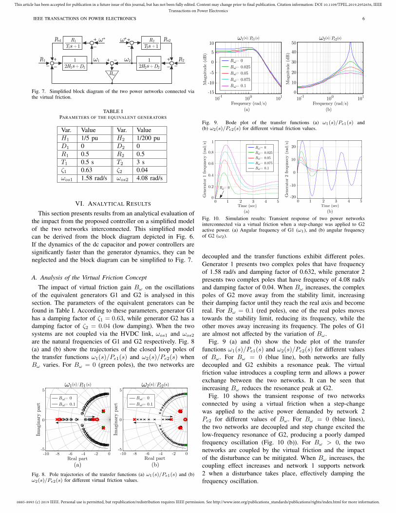
Fig. 7. Simplified block diagram of the two power networks connected viathe virtual friction.
TABLE IPARAMETERS OF THE EQUIVALENT GENERATORS
Var. Value Var. ValueH1 1/5 pu H2 1/200 puD1 0 D2 0R1 0.5 R2 0.5T1 0.5 s T2 3 sζ1 0.63 ζ2 0.04ωos1 1.58 rad/s ωos2 4.08 rad/s
VI. ANALYTICAL RESULTS
This section presents results from an analytical evaluation ofthe impact from the proposed controller on a simplified modelof the two networks interconnected. This simplified modelcan be derived from the block diagram depicted in Fig. 6.If the dynamics of the dc capacitor and power controllers aresignificantly faster than the generator dynamics, they can beneglected and the block diagram can be simplified to Fig. 7.
A. Analysis of the Virtual Friction Concept
The impact of virtual friction gain Bω on the oscillationsof the equivalent generators G1 and G2 is analysed in thissection. The parameters of the equivalent generators can befound in Table I. According to these parameters, generator G1has a damping factor of ζ1 = 0.63, while generator G2 has adamping factor of ζ2 = 0.04 (low damping). When the twosystems are not coupled via the HVDC link, ωos1 and ωos2
are the natural frequencies of G1 and G2 respectively. Fig. 8(a) and (b) show the trajectories of the closed loop poles ofthe transfer functions ω1(s)/Pe1(s) and ω2(s)/Pe2(s) whenBω varies. For Bω = 0 (green poles), the two networks are
Real part Real part
Imag
inar
y p
art
(a) (b)
-10 -8 -6 -4 -2 0-5
0
5
-10 -8 -6 -4 -2 0
B = 0
B = 0.1ω
ω
1(s)/ e1P (s) 2(s)/ e2P (s)
B = 0
B = 0.1ω
ω
Imag
inar
y p
art
-5
0
5
Fig. 8. Pole trajectories of the transfer functions (a) ω1(s)/Pe1(s) and (b)ω2(s)/Pe2(s) for different virtual friction values.
(a)
1(s)/ e1P (s) 2(s)/ e2P (s)
-15
-10
-5
0
5
10
10-1
1000
10
20
30
40
50
101
Magnitude
(dB
)
Frequency (rad/s)
B = 0
B = 0.025
B = 0.05
B = 0.075
B = 0.1
ω
ω
ω
ω
ω
Magnitude
(dB
)
(b)
10-1
100 101
Frequency (rad/s)
Fig. 9. Bode plot of the transfer functions (a) ω1(s)/Pe1(s) and(b) ω2(s)/Pe2(s) for different virtual friction values.
Time (sec)
(b)(a)
Time (sec)0 1 2 3 4 5
0
0.2
0.4
0.6
0.8
1
0 1 2 3 4 5-20
-10
0
10
20
B = 0
Gen
erat
or 1
fre
qunec
y (
rad/s
)
B = 0
B = 0.025
B = 0.05
B = 0.075
B = 0.1
Gen
erat
or 2
fre
qunec
y (
rad/s
)
Fig. 10. Simulation results: Transient response of two power networksinterconnected via a virtual friction when a step-change was applied to G2active power. (a) Angular frequency of G1 (ω1), and (b) angular frequencyof G2 (ω2).
decoupled and the transfer functions exhibit different poles.Generator 1 presents two complex poles that have frequencyof 1.58 rad/s and damping factor of 0.632, while generator 2presents two complex poles that have frequency of 4.08 rad/sand damping factor of 0.04. When Bω increases, the complexpoles of G2 move away from the stability limit, increasingtheir damping factor until they reach the real axis and becomereal. For Bω = 0.1 (red poles), one of the real poles movestowards the stability limit, reducing its frequency, while theother moves away increasing its frequency. The poles of G1are almost not affected by the variation of Bω .
Fig. 9 (a) and (b) show the bode plot of the transferfunctions ω1(s)/Pe1(s) and ω2(s)/Pe2(s) for different valuesof Bω . For Bω = 0 (blue line), both networks are fullydecoupled and G2 exhibits a resonance peak. The virtualfriction value introduces a coupling term and allows a powerexchange between the two networks. It can be seen thatincreasing Bω reduces the resonance peak at G2.
Fig. 10 shows the transient response of two networksconnected by using a virtual friction when a step-changewas applied to the active power demanded by network 2Pe2 for different values of Bω . For Bω = 0 (blue lines),the two networks are decoupled and step change excited thelow-frequency resonance of G2, producing a poorly dampedfrequency oscillation (Fig. 10 (b)). For Bω > 0, the twonetworks are coupled by the virtual friction and the impactof the disturbance can be mitigated. When Bω increases, thecoupling effect increases and network 1 supports network2 when a disturbance takes place, effectively damping thefrequency oscillation.
0885-8993 (c) 2019 IEEE. Personal use is permitted, but republication/redistribution requires IEEE permission. See http://www.ieee.org/publications_standards/publications/rights/index.html for more information.
This article has been accepted for publication in a future issue of this journal, but has not been fully edited. Content may change prior to final publication. Citation information: DOI 10.1109/TPEL.2019.2952656, IEEETransactions on Power Electronics
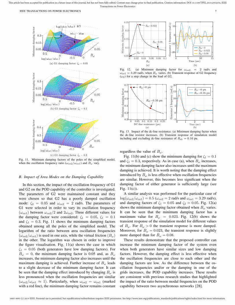
IEEE TRANSACTIONS ON POWER ELECTRONICS 7
(c) G1 damping factor = 0.3
Min
imum
dam
pin
g fa
ctor
0.05
0.05
0.15
0.3
0.05
0.15
0.3
0.2
0.4
(b) G1 damping factor = 0.1
(a) G1 damping factor = 0.05
Min
imum
dam
pin
g fa
ctor
Min
imum
dam
pin
gfa
ctor
1
1
1
log( / )2 1os os
log( / )2 1os os
log( / )2 1os os
Fig. 11. Minimum damping factors of the poles of the simplified model,when the oscillation frequency ratio (ωos2/ωos1) and Bω vary.
B. Impact of Area Modes on the Damping Capability
In this section, the impact of the oscillation frequency of G1and G2 on the POD capability of the controller is investigated.The parameters of G2 were maintained constant and theywere chosen so that G2 has a poorly damped oscillationmode: ζ2 = 0.05 and ωos2 = 2 rad/s. The parameters ofG1 were selected in order to vary its oscillation frequency(ωos1) between ωos2/2 and 2ωos2. Three different values forthe damping factor were considered: ζ1 = 0.05, ζ1 = 0.1and ζ1 = 0.3. Fig. 11 shows the minimum damping factorsobtained among all the poles of the simplified model. Thelogarithm of the ratio between area oscillation frequencies(ωos2/ωos1) is used in one axis, while the virtual friction (Bω)in the other. The logarithm was chosen in order to improvethe figure visualisation. Fig. 11(a) shows the case in whichζ1 = 0.05 (both generators have low damping factors). ForBω = 0, the minimum damping factor is 0.05 and, as Bω
increases, the minimum damping factor also increases until themaximum damping is achieved. Further increase of Bω leadsto a slight decrease of the minimum damping factor. It canbe seen that the damping effect introduced by changing Bω isless pronounced when the oscillation frequencies are similar(ωos2/ωos1 ≈ 1). Particularly, when ωos2 = ωos1 (markedwith a red line), the minimum damping factor remains constant
0 0.02 0.04 0.06 0.08 0.1B
0.05
0.1
0.15
0.2
0.25
Min
imum
dam
pin
g fa
ctor
0 5 10 15
-20
-10
0
10
Gen
erat
or 1
fre
quen
cy (
rad/s
)
Time (sec)
B =0.023
B =0.08
B =0B =0.023B =0.08
B =0
(b)(a)
Fig. 12. (a) Minimum damping factor for ωos2 = 2 rad/s andωos1 = 3.29 rad/s, when Bω varies. (b) Transient response of G2 frequency(ω2) for a step change in the load of G2.
0 1 2 3 4-5
0
5
10
15
20
Gen
erat
or 2
fre
quen
cy (
rad/s
)
Min
imum
dam
pin
g fa
ctor
DC-line resistance (pu) Time (sec)
R =0 pudc
R =0.16 pudc
R =0 pudc
R =0.16 pudc
0 0.05 0.1 0.15 0.2 0.250.2
0.3
0.4
0.5
0.6
0.7
(a) (b)
Fig. 13. Impact of the dc-line resistance: (a) Minimum damping factor whenthe dc-line resistor increases. (b) Transient response of simulation modelincluding and excluding dc-line resistance of Rdc = 0.16 pu.
regardless the value of Bω .Fig. 11(b) and (c) show the minimum damping for ζ1 = 0.1
and ζ1 = 0.3, respectively. As in case (a), when Bω increases,the minimum damping factor also increases until the maximumdamping is achieved. It is worth noting that the damping effectintroduced by Bω is less effective when oscillation frequenciesare similar. However, this becomes less significant when thedamping factor of either generator is sufficiently large (seeFig. 11(c)).
A similar analysis was performed for the particular case oflog(ωos2/ωos1) = 0.5 (ωos2 = 2 rad/s and ωos1 = 3.29 rad/s),and damping factors of ζ1 = 0.05 and ζ2 = 0.05. Fig. 12(a)shows the minimum damping factor obtained when Bω varies.It can be seen that the minimum damping factor has amaximum value for Bω = 0.023. Fig. 12(b) shows thetransient response of the simulation model for different valuesof Bω . For Bω > 0 the transient response is more damped.Moreover, for Bω = 0.023, the transient response is slightlymore damped than for Bω = 0.08.
These results demonstrate that the proposed controller canincrease the minimum damping factor of the system evenwhen both generators have similar sizes and low dampingfactors. However, the damping effect is less effective whenthe oscillation frequencies are close to each other and thedamping factors are low. As the difference between the os-cillation frequencies and/or or the damping in one of thegrids increases, the POD capability increases. These resultsare consistent with previous research studies that highlightedthe impact of the ratio between modal frequencies on the PODcapability between two asynchronous networks [28].
0885-8993 (c) 2019 IEEE. Personal use is permitted, but republication/redistribution requires IEEE permission. See http://www.ieee.org/publications_standards/publications/rights/index.html for more information.
This article has been accepted for publication in a future issue of this journal, but has not been fully edited. Content may change prior to final publication. Citation information: DOI 10.1109/TPEL.2019.2952656, IEEETransactions on Power Electronics
IEEE TRANSACTIONS ON POWER ELECTRONICS 8
AC-Busbar 1
Rectifiers
AC-Busbar 2
AC-Busbar 3
AC-Busbar 4
AC-Busbar 5
Inverters
MainsGrid
AC
DC
AC
DC
AC
DC
AC
DC
AC
DC
AC
DC
DC
AC
DC
AC
DC
AC
DC
AC
DC
AC
DC
AC
G1 G2
2x75kVA2x15kVA
HVDC
2x15kVA
Load 1 Load 2
Fig. 14. Electric diagram of the Smart Energy Integration Lab (SEIL).
C. Impact of the dc Line on the POD Capability
The impact of the dc-line resistance was evaluated analyt-ically and in simulation. The parameters of the equivalentgenerators can be found in Table I. Fig. 13 (a) shows theminimum damping factor when a dc line resistance (Rdc) isincluded in the small-signal model of the complete system.Meanwhile, Fig.13 (b) shows the transient response of thedetailed simulation (grey) excluding and (black) includingthe dc resistance, for Rdc = 0.16 pu. The line resistancedecreases the damping provided by the controller. However,typical values of dc-line resistances are smaller than thevalues considered here. Therefore, the POD capability of thecontroller would not be compromised.
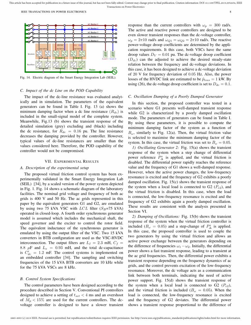
VII. EXPERIMENTAL RESULTS
A. Description of the experimental setup
The proposed virtual friction control system has been ex-perimentally validated in the Smart Energy Integration Lab(SEIL) [34], by a scaled version of the power system depictedin Fig. 1. Fig. 14 shows a schematic diagram of the laboratoryfacilities. The nominal grid voltage and frequency of both acgrids is 400 V and 50 Hz. The ac grids represented in thispaper by the equivalent generators G1 and G2, are emulatedby using two 75 kVA VSC with LCL filter (SB=75 kVA)operated in closed-loop. A fourth order synchronous generatormodel is assumed which includes the mechanical shaft, thespeed governor and the exciter to control the rotor field.The equivalent inductance of the synchronous generator isemulated by using the output filter of the VSC. Two 15 kVAconverters in BTB configuration are used as the VSC-HVDCinterconnection. The output filters are LI = 2.3 mH, Cf =8.8 µF and Lo = 0.93 mH, and the total dc-capacitanceis C ′dc = 1.2 mF. The control systems is implemented onan embedded controller [34]. The sampling and switchingfrequencies of the 15 kVA BTB converters are 10 kHz whilefor the 75 kVA VSCs are 8 kHz.
B. Control System Specifications
The control parameters have been designed according to theprocedure described in Section V. Conventional PI controllersdesigned to achieve a setting of tset < 4 ms and an overshootof Mp < 15% are used for the current controllers. The dc-voltage controller is designed to have a slower transient
response than the current controllers with ωp = 300 rad/s.The active and reactive power controllers are designed to beeven slower transient responses than the dc-voltage controller,ωp = 2π10 rad/s and ωQ1 = ωQ2 = 2π10 rad/s. The reactivepower-voltage droop coefficients are determined by the appli-cation requirements. It this case, both VSCs have the samedroop values DV = 0.01 pu. The dc-voltage droop coefficient(Ddc) can the adjusted to achieve the desired steady-staterelation between the frequency and dc-voltage deviations. Inthis case, it has been designed to achieve a dc-voltage deviationof 20 V for frequency deviation of 0.05 Hz. Also, the powerlosses of the HVDC link are estimated to be ploss = 1 kW. Byusing (26), the dc-voltage droop coefficient is set to Ddc = 0.1.
C. Oscillation Damping of a Poorly Damped Generator
In this section, the proposed controller was tested in ascenario where G1 presents well-damped transient responsewhile G2 is characterized by a poorly damped oscillationmode. The parameters of generators can be found in Table I.By using these parameters, it is possible to compute theminimum damping factor of the system as a function ofBω , similarly to Fig. 12(a). Then, the virtual friction valueis selected to maximise the minimum damping factor of thesystem. In this case, the virtual friction was set to Bω = 0.05.
1) Oscillating Generator 2: Fig. 15(a) shows the transientresponse of the system when a step change of differentialpower reference P ∗∆ is applied, and the virtual friction isdisabled. The differential power rapidly reaches the referencevalue and the frequency of G1 shows a well-damped response.However, when the active power changes, the low-frequencyresonance is excited and the frequency of G2 exhibits a poorlydamped oscillation. Fig. 15(c) shows the transient response ofthe system when a local load is connected to G2 (Pe2), andthe virtual friction is disabled. In this case, when the loadis connected, the low-frequency resonance is excited and thefrequency of G2 exhibits again a poorly damped oscillation.These results are consistent with the analysis presented inSection VI.
2) Damping of Oscillations: Fig. 15(b) shows the transientresponse of the system when the virtual friction controller isincluded (Bω = 0.05) and a step-change of P ∗∆ is applied.In this case, the proposed controller is used to couple thetwo generators by using the virtual friction and allows anactive power exchange between the generators depending onthe difference of frequencies ω1−ω2. Initially, the differentialpower shows a fast transient response, leading to a transient atthe ac grid frequencies. Then, the differential power exhibits atransient response depending on the frequency dynamics of acgrids, and the control prevents excitation of the low-frequencyresonance. Moreover, the dc voltage acts as a communicationlink between both terminals, indicating the need of activepower support. Fig. 15(d) shows the transient response ofthe system when a local load is connected to G2 (Pe2),and the virtual friction is included (Bω = 0.05). When theload is connected, the low-frequency resonance is excitedand the frequency of G2 deviates. The differential powershows a transient response proportional to the difference of
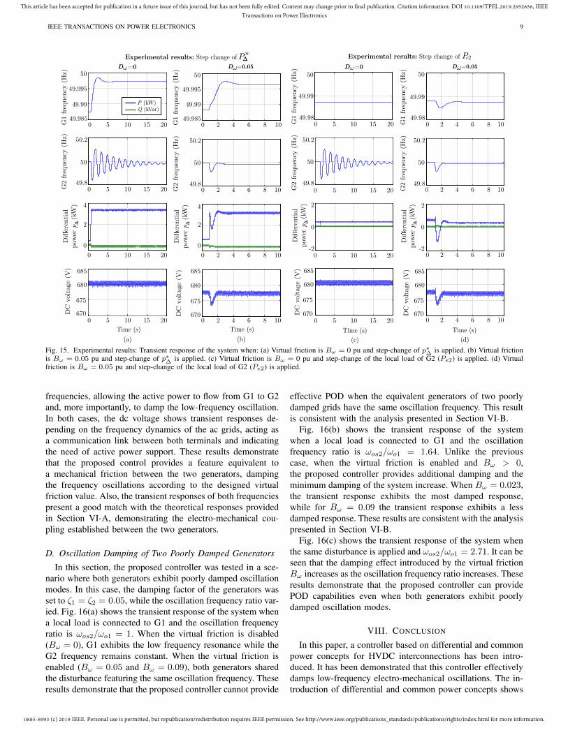
0885-8993 (c) 2019 IEEE. Personal use is permitted, but republication/redistribution requires IEEE permission. See http://www.ieee.org/publications_standards/publications/rights/index.html for more information.
This article has been accepted for publication in a future issue of this journal, but has not been fully edited. Content may change prior to final publication. Citation information: DOI 10.1109/TPEL.2019.2952656, IEEETransactions on Power Electronics
IEEE TRANSACTIONS ON POWER ELECTRONICS 9
G1 fre
quen
cy (
Hz)
D =0 D =0.05
0 2 4 6 8 1049.985
49.99
49.995
50
0 2 4 6 8 1049.98
49.99
50
0 2 4 6 8 1049.8
50
50.2
0 2 4 6 8 1049.8
50
50.2
0 2 4 6 8 10
0
2
4
0 2 4 6 8 10-2
0
2
0 2 4 6 8 10670
675
680
685
0 2 4 6 8 10670
675
680
685
G1 fre
quen
cy (
Hz)
G2 fre
quen
cy (
Hz)
Di
eren
tial
pow
er p
(k
W)
Δ
DC
voltage
(V)
G1 fre
quen
cy (
Hz)
G2 fre
quen
cy (
Hz)
Di
eren
tial
pow
er p
(k
W)
Δ
DC
voltage
(V)
Time (s) Time (s)
(b) (d)
D =0 D =0.05
0 5 10 15 2049.985
49.99
49.995
50
0 5 10 15 2049.8
50
50.2
0 5 10 15 2049.8
50
50.2
0 5 10 15 20
0
2
4
0 5 10 15 20
0 5 10 15 20670
675
680
685
0 5 10 15 20670
675
680
685
G1 fre
quen
cy (
Hz)
G2 fre
quen
cy (
Hz)
G2 fre
quen
cy (
Hz)
Di
eren
tial
pow
er p
(k
W)
Δ
Di
eren
tial
pow
er p
(k
W)
Δ
DC
voltage
(V)
DC
voltage
(V)
Time (s) Time (s)
(a) (c)
Q (kVar)P (kW)
-2
0
2
0 5 10 15 2049.98
49.99
50
Experimental results: Step change of PΔ* Experimental results: Step change of Pe2
Fig. 15. Experimental results: Transient response of the system when: (a) Virtual friction is Bω = 0 pu and step-change of p∗∆ is applied. (b) Virtual frictionis Bω = 0.05 pu and step-change of p∗∆ is applied. (c) Virtual friction is Bω = 0 pu and step-change of the local load of G2 (Pe2) is applied. (d) Virtualfriction is Bω = 0.05 pu and step-change of the local load of G2 (Pe2) is applied.
frequencies, allowing the active power to flow from G1 to G2and, more importantly, to damp the low-frequency oscillation.In both cases, the dc voltage shows transient responses de-pending on the frequency dynamics of the ac grids, acting asa communication link between both terminals and indicatingthe need of active power support. These results demonstratethat the proposed control provides a feature equivalent toa mechanical friction between the two generators, dampingthe frequency oscillations according to the designed virtualfriction value. Also, the transient responses of both frequenciespresent a good match with the theoretical responses providedin Section VI-A, demonstrating the electro-mechanical cou-pling established between the two generators.
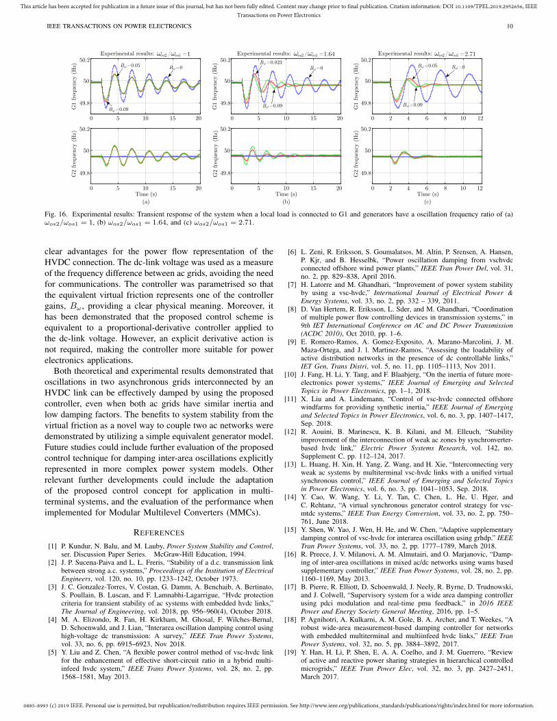
D. Oscillation Damping of Two Poorly Damped Generators
In this section, the proposed controller was tested in a sce-nario where both generators exhibit poorly damped oscillationmodes. In this case, the damping factor of the generators wasset to ζ1 = ζ2 = 0.05, while the oscillation frequency ratio var-ied. Fig. 16(a) shows the transient response of the system whena local load is connected to G1 and the oscillation frequencyratio is ωos2/ωo1 = 1. When the virtual friction is disabled(Bω = 0), G1 exhibits the low frequency resonance while theG2 frequency remains constant. When the virtual friction isenabled (Bω = 0.05 and Bω = 0.09), both generators sharedthe disturbance featuring the same oscillation frequency. Theseresults demonstrate that the proposed controller cannot provide
effective POD when the equivalent generators of two poorlydamped grids have the same oscillation frequency. This resultis consistent with the analysis presented in Section VI-B.
Fig. 16(b) shows the transient response of the systemwhen a local load is connected to G1 and the oscillationfrequency ratio is ωos2/ωo1 = 1.64. Unlike the previouscase, when the virtual friction is enabled and Bω > 0,the proposed controller provides additional damping and theminimum damping of the system increase. When Bω = 0.023,the transient response exhibits the most damped response,while for Bω = 0.09 the transient response exhibits a lessdamped response. These results are consistent with the analysispresented in Section VI-B.
Fig. 16(c) shows the transient response of the system whenthe same disturbance is applied and ωos2/ωo1 = 2.71. It can beseen that the damping effect introduced by the virtual frictionBω increases as the oscillation frequency ratio increases. Theseresults demonstrate that the proposed controller can providePOD capabilities even when both generators exhibit poorlydamped oscillation modes.
VIII. CONCLUSION
In this paper, a controller based on differential and commonpower concepts for HVDC interconnections has been intro-duced. It has been demonstrated that this controller effectivelydamps low-frequency electro-mechanical oscillations. The in-troduction of differential and common power concepts shows
0885-8993 (c) 2019 IEEE. Personal use is permitted, but republication/redistribution requires IEEE permission. See http://www.ieee.org/publications_standards/publications/rights/index.html for more information.
This article has been accepted for publication in a future issue of this journal, but has not been fully edited. Content may change prior to final publication. Citation information: DOI 10.1109/TPEL.2019.2952656, IEEETransactions on Power Electronics
IEEE TRANSACTIONS ON POWER ELECTRONICS 10
Time (s)
0 5 10 15 20
49.8
50
50.2
0 5 10 15 20
49.8
50
50.2
0 5 10 15 20
49.8
50
50.2
0 5 10 15 20
49.8
50
50.2
0 2 4 6 8 10 12
49.8
50
50.2
0 2 4 6 8 10 12
49.8
50
50.2
G1
freq
uen
cy (
Hz)
G2
freq
uen
cy (
Hz)
G1
freq
uen
cy (
Hz)
G2
freq
uen
cy (
Hz)
G1
freq
uen
cy (
Hz)
G2
freq
uen
cy (
Hz)
Time (s) Time (s)
(a) (b) (c)
B =0B =0.023
B =0.09
B =0B =0.05
B =0.09
B =0B =0.05
B =0.09
Experimental results: os1os2 =1.64/Experimental results: os1os2 =1/ Experimental results: os1os2 =2.71/
Fig. 16. Experimental results: Transient response of the system when a local load is connected to G1 and generators have a oscillation frequency ratio of (a)ωos2/ωos1 = 1, (b) ωos2/ωos1 = 1.64, and (c) ωos2/ωos1 = 2.71.
clear advantages for the power flow representation of theHVDC connection. The dc-link voltage was used as a measureof the frequency difference between ac grids, avoiding the needfor communications. The controller was parametrised so thatthe equivalent virtual friction represents one of the controllergains, Bω , providing a clear physical meaning. Moreover, ithas been demonstrated that the proposed control scheme isequivalent to a proportional-derivative controller applied tothe dc-link voltage. However, an explicit derivative action isnot required, making the controller more suitable for powerelectronics applications.
Both theoretical and experimental results demonstrated thatoscillations in two asynchronous grids interconnected by anHVDC link can be effectively damped by using the proposedcontroller, even when both ac grids have similar inertia andlow damping factors. The benefits to system stability from thevirtual friction as a novel way to couple two ac networks weredemonstrated by utilizing a simple equivalent generator model.Future studies could include further evaluation of the proposedcontrol technique for damping inter-area oscillations explicitlyrepresented in more complex power system models. Otherrelevant further developments could include the adaptationof the proposed control concept for application in multi-terminal systems, and the evaluation of the performance whenimplemented for Modular Multilevel Converters (MMCs).
REFERENCES
[1] P. Kundur, N. Balu, and M. Lauby, Power System Stability and Control,ser. Discussion Paper Series. McGraw-Hill Education, 1994.
[2] J. P. Sucena-Paiva and L. L. Freris, “Stability of a d.c. transmission linkbetween strong a.c. systems,” Proceedings of the Institution of ElectricalEngineers, vol. 120, no. 10, pp. 1233–1242, October 1973.
[3] J. C. Gonzalez-Torres, V. Costan, G. Damm, A. Benchaib, A. Bertinato,S. Poullain, B. Luscan, and F. Lamnabhi-Lagarrigue, “Hvdc protectioncriteria for transient stability of ac systems with embedded hvdc links,”The Journal of Engineering, vol. 2018, pp. 956–960(4), October 2018.
[4] M. A. Elizondo, R. Fan, H. Kirkham, M. Ghosal, F. Wilches-Bernal,D. Schoenwald, and J. Lian, “Interarea oscillation damping control usinghigh-voltage dc transmission: A survey,” IEEE Tran Power Systems,vol. 33, no. 6, pp. 6915–6923, Nov 2018.
[5] Y. Liu and Z. Chen, “A flexible power control method of vsc-hvdc linkfor the enhancement of effective short-circuit ratio in a hybrid multi-infeed hvdc system,” IEEE Trans Power Systems, vol. 28, no. 2, pp.1568–1581, May 2013.
[6] L. Zeni, R. Eriksson, S. Goumalatsos, M. Altin, P. Srensen, A. Hansen,P. Kjr, and B. Hesselbk, “Power oscillation damping from vschvdcconnected offshore wind power plants,” IEEE Tran Power Del, vol. 31,no. 2, pp. 829–838, April 2016.
[7] H. Latorre and M. Ghandhari, “Improvement of power system stabilityby using a vsc-hvdc,” International Journal of Electrical Power &Energy Systems, vol. 33, no. 2, pp. 332 – 339, 2011.
[8] D. Van Hertem, R. Eriksson, L. Sder, and M. Ghandhari, “Coordinationof multiple power flow controlling devices in transmission systems,” in9th IET International Conference on AC and DC Power Transmission(ACDC 2010), Oct 2010, pp. 1–6.
[9] E. Romero-Ramos, A. Gomez-Exposito, A. Marano-Marcolini, J. M.Maza-Ortega, and J. l. Martinez-Ramos, “Assessing the loadability ofactive distribution networks in the presence of dc controllable links,”IET Gen, Trans Distri, vol. 5, no. 11, pp. 1105–1113, Nov 2011.
[10] J. Fang, H. Li, Y. Tang, and F. Blaabjerg, “On the inertia of future more-electronics power systems,” IEEE Journal of Emerging and SelectedTopics in Power Electronics, pp. 1–1, 2018.
[11] X. Liu and A. Lindemann, “Control of vsc-hvdc connected offshorewindfarms for providing synthetic inertia,” IEEE Journal of Emergingand Selected Topics in Power Electronics, vol. 6, no. 3, pp. 1407–1417,Sep. 2018.
[12] R. Aouini, B. Marinescu, K. B. Kilani, and M. Elleuch, “Stabilityimprovement of the interconnection of weak ac zones by synchronverter-based hvdc link,” Electric Power Systems Research, vol. 142, no.Supplement C, pp. 112–124, 2017.
[13] L. Huang, H. Xin, H. Yang, Z. Wang, and H. Xie, “Interconnecting veryweak ac systems by multiterminal vsc-hvdc links with a unified virtualsynchronous control,” IEEE Journal of Emerging and Selected Topicsin Power Electronics, vol. 6, no. 3, pp. 1041–1053, Sep. 2018.
[14] Y. Cao, W. Wang, Y. Li, Y. Tan, C. Chen, L. He, U. Hger, andC. Rehtanz, “A virtual synchronous generator control strategy for vsc-mtdc systems,” IEEE Tran Energy Conversion, vol. 33, no. 2, pp. 750–761, June 2018.
[15] Y. Shen, W. Yao, J. Wen, H. He, and W. Chen, “Adaptive supplementarydamping control of vsc-hvdc for interarea oscillation using grhdp,” IEEETran Power Systems, vol. 33, no. 2, pp. 1777–1789, March 2018.
[16] R. Preece, J. V. Milanovi, A. M. Almutairi, and O. Marjanovic, “Damp-ing of inter-area oscillations in mixed ac/dc networks using wams basedsupplementary controller,” IEEE Tran Power Systems, vol. 28, no. 2, pp.1160–1169, May 2013.
[17] B. Pierre, R. Elliott, D. Schoenwald, J. Neely, R. Byrne, D. Trudnowski,and J. Colwell, “Supervisory system for a wide area damping controllerusing pdci modulation and real-time pmu feedback,” in 2016 IEEEPower and Energy Society General Meeting, 2016, pp. 1–5.
[18] P. Agnihotri, A. Kulkarni, A. M. Gole, B. A. Archer, and T. Weekes, “Arobust wide-area measurement-based damping controller for networkswith embedded multiterminal and multiinfeed hvdc links,” IEEE TranPower Systems, vol. 32, no. 5, pp. 3884–3892, 2017.
[19] Y. Han, H. Li, P. Shen, E. A. A. Coelho, and J. M. Guerrero, “Reviewof active and reactive power sharing strategies in hierarchical controlledmicrogrids,” IEEE Tran Power Elec, vol. 32, no. 3, pp. 2427–2451,March 2017.
0885-8993 (c) 2019 IEEE. Personal use is permitted, but republication/redistribution requires IEEE permission. See http://www.ieee.org/publications_standards/publications/rights/index.html for more information.
This article has been accepted for publication in a future issue of this journal, but has not been fully edited. Content may change prior to final publication. Citation information: DOI 10.1109/TPEL.2019.2952656, IEEETransactions on Power Electronics
IEEE TRANSACTIONS ON POWER ELECTRONICS 11
[20] Y. Phulpin, “Communication-free inertia and frequency control for windgenerators connected by an hvdc-link,” IEEE Tran Power Systems,vol. 27, no. 2, pp. 1136–1137, May 2012.
[21] J. Rafferty, L. Xu, Y. Wang, G. Xu, and F. Alsokhiry, “Frequency supportusing multi-terminal hvdc systems based on dc voltage manipulation,”IET Renewable Power Gen, vol. 10, no. 9, pp. 1393–1401, 2016.
[22] A. E. Leon, “Short-term frequency regulation and inertia emulation usingan mmc-based mtdc system,” IEEE Tran Power Systems, vol. 33, no. 3,pp. 2854–2863, May 2018.
[23] K. Rouzbehi, W. Zhang, J. Ignacio Candela, A. Luna, and P. Rodriguez,“Unified reference controller for flexible primary control and inertiasharing in multi-terminal voltage source converter-hvdc grids,” IET Gen,Tran Distr, vol. 11, no. 3, pp. 750–758, 2017.
[24] A. Rodrıguez-Cabero, J. Roldan-Perez, M. Prodanovic, J. A. Suul, andS. D’Arco, “Virtual friction control for power system oscillation damp-ing with vsc-hvdc links,” in 2019 IEEE Energy Conversion Congressand Exposition (ECCE). IEEE, 2019, pp. 1–6.
[25] A. Rodrıguez-Cabero, M. Prodanovic, and J. Roldan-Perez, “Full-statefeedback control of back-to-back converters based on differential andcommon power concepts,” IEEE Tran Ind Elec, pp. 1–1, 2018.
[26] H. Bevrani, B. Francois, and T. Ise, Microgrid Dynamics and Control.Wiley, 2017.
[27] E. Rakhshani, D. Remon, A. Mir Cantarellas, and P. Rodriguez, “Anal-ysis of derivative control based virtual inertia in multi-area high-voltagedirect current interconnected power systems,” IET Gen, Trans Distr,vol. 10, no. 6, pp. 1458–1469, 2016.
[28] J. Bjork, K. H. Johansson, and L. Harnefors, “Fundamental performancelimitations in utilizing hvdc to damp interarea modes,” IEEE Transac-tions on Power Systems, vol. 34, no. 2, pp. 1095–1104, March 2019.
[29] A. Rodrıguez-Cabero, J. Roldan-Perez, M. Prodanovic, J. A. Suul, andS. D’Arco, “Virtual friction control for oscillation damping with vsc-hvdc links,” in ECCE (submitted), 2019.
[30] A. Kirakosyan, E. F. El-Saadany, M. S. E. Moursi, and K. Al Hosani,“DC Voltage Regulation and Frequency Support in Pilot Voltage Droop-Controlled Multiterminal HVdc Systems,” IEEE Trans Power Del,vol. 33, no. 3, pp. 1153–1164, 2018.
[31] H. Akagi, Y. Kanazawa, and A. Nabae, “Instantaneous reactive powercompensators comprising switching devices without energy storagecomponents,” IEEE Tran Ind Appli, vol. IA-20, no. 3, pp. 625–630,May 1984.
[32] R. G. Lyons, Understanding Digital Signal Processing, 1st ed. Boston,MA, USA: Addison-Wesley Longman Publishing Co., Inc., 1996.
[33] A. Yazdani and R. Iravani, Voltage-Sourced Converters in Power Sys-tems: Modeling, Control, and Applications. Wiley-IEEE Press, 2010.
[34] M. Prodanovic, A. Rodrıguez-Cabero, M. Jimenez-Carrizosa, andJ. Roldan-Perez, “A rapid prototyping environment for dc and acmicrogrids: Smart energy integration lab (seil),” in ICDCM 2017, June2017, pp. 421–427.
Alberto Rodrıguez-Cabero obtained his degreesin Industrial Technical Engineering and IndustrialEngineering specialized in Electronics in 2011 and2013, respectively, both from Comillas PontificalUniversity. In 2016, he obtained the Master in Re-search in Engineering Systems Modelling in thesame University. From 2014 to 2015, he worked ascontrol engineer at Institute for Research in Tech-nology (IIT), Comillas Pontifical University, Madrid.Since September 2015 he is working in the ElectricalSystems Unit, Institute IMDEA Energy, Madrid. His
areas of interest include the design and control of power electronics converters,power quality and micro-grids.
Javier Roldan-Perez (S’12-M’14) received a B.S.degree in industrial engineering, a M.S. degree inelectronics and control systems, a M.S. degree insystem modeling, and a Ph.D. degree in powerelectronics, all from Comillas Pontifical University,Madrid, in 2009, 2010, 2011, and 2015, respectively.From 2010 to 2015, he was with the Institute forResearch in Technology (IIT), Comillas University.In 2014, he was a visiting Ph.D. student at theDepartment of Energy Technology, Aalborg Univer-sity, Denmark. From 2015 to 2016 he was with the
Electric and Control Systems Department at Norvento Energıa Distribuida.Currently he is a Senior Assistant Researcher at the Electrical SystemsUnit of Institute IMDEA Energy, Madrid, Spain. His research topics arethe integration of renewable energies, microgrids, and power electronicsapplications.
Milan Prodanovic (M’01) received the B.Sc. de-gree in electrical engineering from the University ofBelgrade, Serbia, in 1996 and the Ph.D. degree fromImperial College, London, U.K., in 2004. From 1997to 1999 he was with GVS engineering company,Serbia, developing UPS systems. From 1999 until2010 he was a research associate in Electrical andElectronic Engineering at Imperial College, London,UK. Currently he is a Senior Researcher and Headof the Electrical Systems Unit at Institute IMDEAEnergy, Madrid, Spain. He authored a number of
highly cited articles and is the holder of three patents. His research interestsinclude design and control of power electronics interfaces for distributedgeneration, micro-grids stability and control and active management ofdistribution networks.
Jon Are Suul (M’11) received the M.Sc. degreein energy and environmental engineering and thePh.D. degree in electric power engineering from theNorwegian University of Science and Technology(NTNU), Trondheim, Norway, in 2006 and 2012, re-spectively. From 2006 to 2007, he was with SINTEFEnergy Research, Trondheim, where he was workingwith simulation of power electronic converters andmarine propulsion systems until starting his PhDstudies. From 2012, he resumed a position as aResearch Scientist at SINTEF Energy Research, first
in part-time position while also working as a part-time postdoctoral researcherat the Department of Electric Power Engineering of NTNU until 2016. SinceAugust 2017, he is serving as an Adjunct Associate Professor at the Depart-ment of Engineering Cybernetic of NTNU. His research interests are mainlyrelated to modelling, analysis and control of power electronic convertersin HVDC transmission, renewable energy applications and electrification oftransport.
Salvatore D’Arco received the M.Sc. andPh.D.degrees in electrical engineering from theUniversity of Naples Federico II, Naples, Italy,in 2002 and 2005, respectively. He was, from2006 to 2007, a Postdoctoral Researcher withthe University of South Carolina, Columbia, SC,USA. In 2008, he joined ASML Holding N.V.,Veldhoven, The Netherlands, where he worked asa Power Electronics Designer until 2010. From2010 to 2012, he was a Postdoctoral Researcherwith the Department of Electric Power Engineering,
Faculty of Information Technology, Mathematics and Electrical Engineering,Norwegian University of Science and Technology, Trondheim, Norway.In 2012, he joined SINTEF Energy Research, Trondheim, Norway, wherehe currently works as a Senior Research Scientist. He is the author ofover 100 scientific papers, and he is the holder of one patent. His mainresearch activities are related to the control and analysis of power electronicconversion systems for power system applications, including the real-timesimulation and rapid prototyping of converter control systems.

![Overview of the Configuration and Power Converters in High ... · Fig. 8. Basic scheme of the LCC-HVDC and VSC-HVDC transmission system [6]. Comparison of the CSC-HVDC and VSC-HVDC](https://img.pdfslide.us/doc/110x75/5ebc0e8dd027f5592e56ad65/overview-of-the-configuration-and-power-converters-in-high-fig-8-basic-scheme.jpg)