Embed Size (px)
Citation preview

BUILDING CONSTRUCTION
HANDBOOK

BUILDINGCONSTRUCTIONHANDBOOKSeventh edition
R. ChudleyMCIOB
and
R. GreenoBA (Hons) FCIOB FIPHE FRSA
AMSTERDAM . BOSTON . HEIDELBERG . LONDON . NEW YORK . OXFORD
PARIS . SAN DIEGO . SAN FRANCISCO . SINGAPORE . SYDNEY . TOKYO
Butterworth-Heinemann is an imprint of Elsevier

Butterworth-Heinemann is an imprint of Elsevier
Linacre House, Jordan Hill, Oxford OX2 8DP, UK
30 Corporate Drive, Suite 400, Burlington, MA 01803, USA
First edition 1988
Second edition 1995
Third edition 1998
Fourth edition 2001
Fifth edition 2004
Sixth edition 2006
Seventh edition 2008
Copyright ª 1988, 1995, 1996, R. Chudley.
Copyright ª 1998, 2001, 2004, 2006, 2008, R. Chudley and R. Greeno
Published by Elsevier Ltd. All rights reserved
Illustrations by the authors
The right of R. Chudley and R. Greeno to be identified as the authors of this work
has been asserted in accordance with the Copyright, Designs and Patents Act 1988
No part of this publication may be reproduced, stored in a retrieval system
or transmitted in any form or by any means electronic, mechanical, photocopying,
recording or otherwise without the prior written permission of the publisher
Permissions may be sought directly from Elsevier’s Science & Technology Rights
Department in Oxford, UK: phone (+44) (0) 1865 843830; fax (+44) (0) 1865 853333;
email: [email protected]. Alternatively you can submit your request online by
visiting the Elsevier website at http://elsevier.com/locate/permissions, and selecting
Obtaining permission to use Elsevier material
Notice
No responsibility is assumed by the publisher for any injury and/or damage to persons
or property as a matter of products liability, negligence or otherwise, or from any use
or operation of any methods, products, instructions or ideas contained in the material
herein. Because of rapid advances in the medical sciences, in particular, independent
verification of diagnoses and drug dosages should be made
British Library Cataloguing in Publication Data
A catalogue record for this book is available from the British Library
Library of Congress Cataloging-in-Publication Data Control Number: 2005938728
ISBN: 978-0-7506-86228
Typeset by Integra Software Services
Printed and bound in Great Britain
08 09 10 11 11 10 9 8 7 6 5 4 3 2
For information on all Butterworth-Heinemann publicationsvisit our website at books.elsevier.com
This Low Priced Edition is only for sale in Africa, the Middle East and selectedEastern European countries. Please contact the Elsevier Books Customer Serviceteam to obtain a list of the countries eligible. In all other countries the regularedition is available with the ISBNs: 978-0-7506-6822-4 or 0-7506-6822-9Elsevier Books Customer ServicePhone: +44 01865 464100 Fax: +44 1865 474101Email: [email protected]
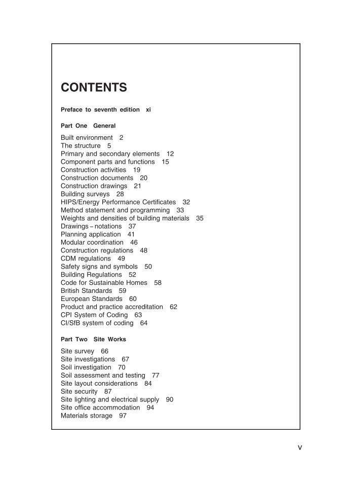
CONTENTS
Preface to seventh edition xi
Part One General
Built environment 2The structure 5Primary and secondary elements 12Component parts and functions 15Construction activities 19Construction documents 20Construction drawings 21Building surveys 28HIPS/Energy Performance Certificates 32Method statement and programming 33Weights and densities of building materials 35Drawings -- notations 37Planning application 41Modular coordination 46Construction regulations 48CDM regulations 49Safety signs and symbols 50Building Regulations 52Code for Sustainable Homes 58British Standards 59European Standards 60Product and practice accreditation 62CPI System of Coding 63CI/SfB system of coding 64
Part Two Site Works
Site survey 66Site investigations 67Soil investigation 70Soil assessment and testing 77Site layout considerations 84Site security 87Site lighting and electrical supply 90Site office accommodation 94Materials storage 97
v
Materials testing 102Protection orders for trees and structures 109Locating public utility services 110Setting out 111Levels and angles 115Road construction 118Tubular scaffolding and scaffolding systems 126Shoring systems 139Demolition 147
Part Three Builders Plant
General considerations 152Bulldozers 155Scrapers 156Graders 157Tractor shovels 158Excavators 159Transport vehicles 164Hoists 167Rubble chutes and skips 169Cranes 170Concreting plant 182
Part Four Substructure
Foundations -- function, materials and sizing 190Foundation beds 199Short bored pile foundations 205Foundation types and selection 207Piled foundations 212Retaining walls 230Gabions and mattresses 244Basement construction 251Waterproofing basements 254Excavations 260Concrete production 266Cofferdams 272Caissons 274Underpinning 276Ground water control 285Soil stabilisation and improvement 295Reclamation of waste land 300Contaminated sub-soil treatment 301
Contents
vi
Part Five Superstructure † 1
Choice of materials 304Brick and block walls 305Cavity walls 320Damp-proof courses and membranes 326Gas resistant membranes 333Calculated brickwork 335Mortars 338Arches and openings 341Windows 348Glass and glazing 361Doors 373Crosswall construction 382Framed construction 386Cladding to external walls 390Roofs -- basic forms 392Pitched roofs 395Plain tiling 402Single lap tiling 408Slating 410Flat roofs 416Dormer windows 419Dry and wet rot 428Green roofs 430Thermal insulation 432‘U’ values 437Thermal bridging 452Access for the disabled 456
Part Six Superstructure † 2
Reinforced concrete slabs 461Reinforced concrete framed structures 464Reinforcement types 474Structural concrete, fire protection 476Formwork 478Precast concrete frames 483Prestressed concrete 487Structural steelwork sections 494Structural steelwork connections 499Structural fire protection 504Portal frames 510Composite timber beams 518Multi-storey structures 520Roof sheet coverings 524
Contents
vii
Long span roofs 529Shell roof construction 536Membrane roofs 544Rooflights 546Panel walls 552Rainscreen cladding 556Structural glazing 558Curtain walling 559Concrete claddings 563Concrete surface finishes 566Concrete surface defects 568
Part Seven Internal Construction and Finishes
Internal elements 570Internal walls 571Construction joints 576Internal walls, fire protection 578Party/separating walls 579Partitions 581Plasters and plastering 587Dry lining techniques 589Wall tiling 593Domestic floors and finishes 595Large cast in-situ ground floors 602Concrete floor screeds 604Timber suspended floors 606Lateral restraint 608Timber beam design 612Timber floors, fire protection 614Reinforced concrete suspended floors 615Precast concrete floors 620Raised access floors 623Sound insulation 625Timber, concrete and metal stairs 629Internal doors 654Doorsets 657Fire resisting doors 658Plasterboard ceilings 664Suspended ceilings 665Paints and painting 669Joinery production 673Composite boarding 678Plastics in building 680
Contents
viii
Part Eight Domestic Services
Drainage effluents 682Subsoil drainage 683Surface water removal 685Road drainage 688Rainwater installations 692Drainage systems 694Drainage pipe sizes and gradients 702Water supply 703Cold water installations 705Hot water installations 707Flow controls 710Cisterns and cylinders 711Pipework joints 713Sanitary fittings 714Single and ventilated stack systems 717Domestic hot water heating systems 720Electrical supply and installation 724Gas supply and gas fires 733Services--fire stops and seals 737Open fireplaces and flues 738Telephone installations 747Electronic communications installations 748
Index 749
ix
Contents

PREFACE TO SEVENTH EDITION
The presentation of this seventh edition continues the familiar and uniqueformat of clear illustrations supplemented with comprehensive notes throughout.The benefit of data accumulated from the numerous previous editions, permitstraditional construction techniques to be retained alongside contemporary anddeveloping practice. Established procedures are purposely retained with regardto maintenance and refurbishment of existing building stock.
Progressive development, new initiatives and government directives to reducefuel energy consumption in buildings by incorporating sustainable and energyefficient features is included. In support of these environmental issues, thecompanion volume Building Services Handbook should be consulted for applica-tions to energy consuming systems, their design and incorporation within thestructure.
The diverse nature of modern construction practice, techniques and develop-ments with new and synthetic materials cannot be contained in this volumealone. The content is therefore intended as representative and not prescriptive.Further reading of specific topics is encouraged, especially through professionaljournals, trade and manufacturers’ literature, illustrative guides to the BuildingRegulations and the supplementary references given hereinafter.
R.G.
xi

1 GENERAL
BUILT ENVIRONMENT
THE STRUCTURE
PRIMARY AND SECONDARY ELEMENTS
CONSTRUCTION ACTIVITIES
CONSTRUCTION DOCUMENTS
CONSTRUCTION DRAWINGS
BUILDING SURVEY
HIPS/EPCs
PLANNING APPLICATION
MODULAR COORDINATION
CONSTRUCTION REGULATIONS
CDM REGULATIONS
SAFETY SIGNS AND SYMBOLS
BUILDING REGULATIONS
CODE FOR SUSTAINABLE HOMES
BRITISH STANDARDS
EUROPEAN STANDARDS
CPI SYSTEM OF CODING
CI/SFB SYSTEM OF CODING
1
Environment = surroundings which can be natural, man-made or a
combination of these.
Built Environment = created by man with or without the aid of the
natural environment.
2
Built Environment
Environmental Considerations
1. Planning requirements.
2. Building Regulations.
3. Land restrictions by vendor
or lessor.
4. Availability of services.
5. Local amenities including
transport.
6. Subsoil conditions.
7. Levels and topography of
land.
8. Adjoining buildings or land.
9. Use of building.
10. Daylight and view aspects.
3
Built Environment
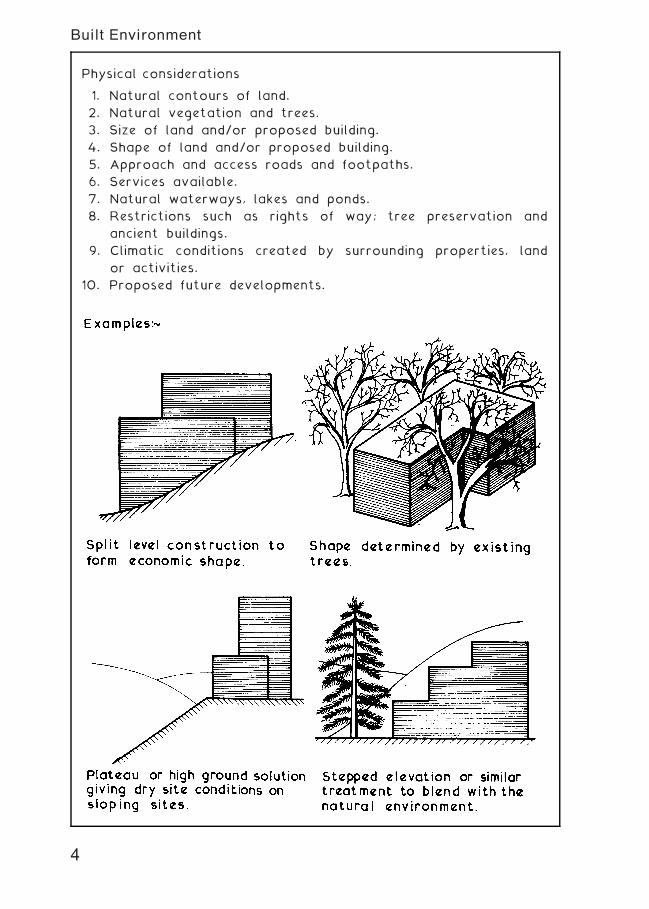
Physical considerations
1. Natural contours of land.
2. Natural vegetation and trees.
3. Size of land and/or proposed building.
4. Shape of land and/or proposed building.
5. Approach and access roads and footpaths.
6. Services available.
7. Natural waterways, lakes and ponds.
8. Restrictions such as rights of way; tree preservation and
ancient buildings.
9. Climatic conditions created by surrounding properties, land
or activities.
10. Proposed future developments.
4
Built Environment
5
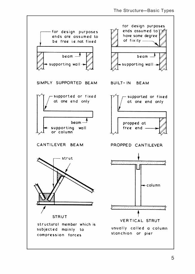
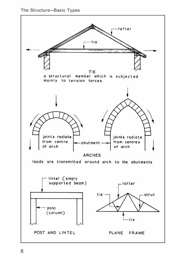
The Structure---Basic Types
6
The Structure---Basic Types
7
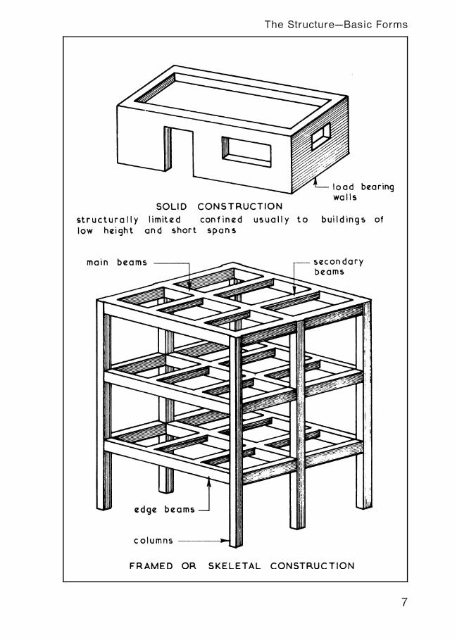
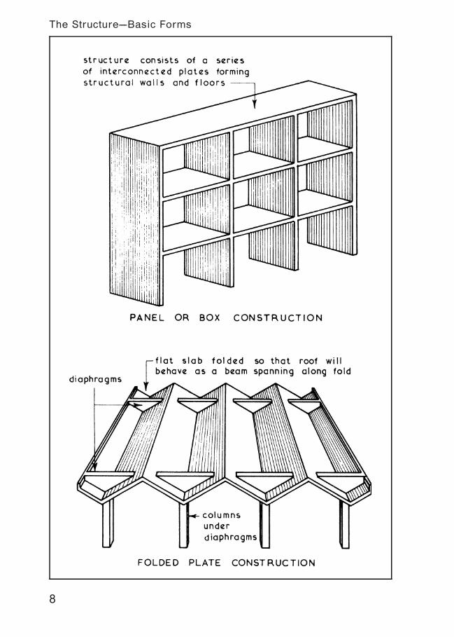
The Structure---Basic Forms
8
The Structure---Basic Forms
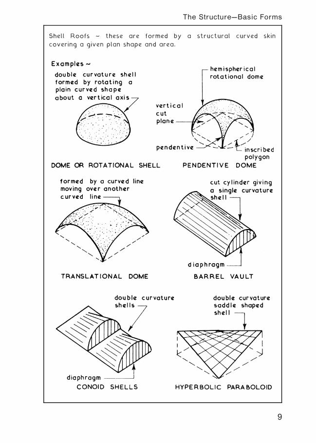
Shell Roofs ~ these are formed by a structural curved skin
covering a given plan shape and area.
9
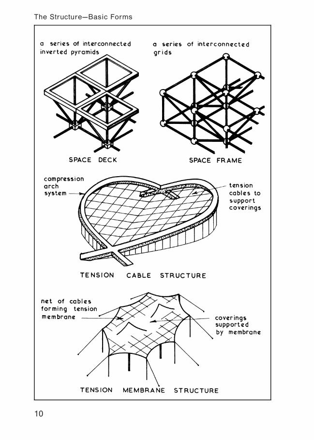
The Structure---Basic Forms
10
The Structure---Basic Forms
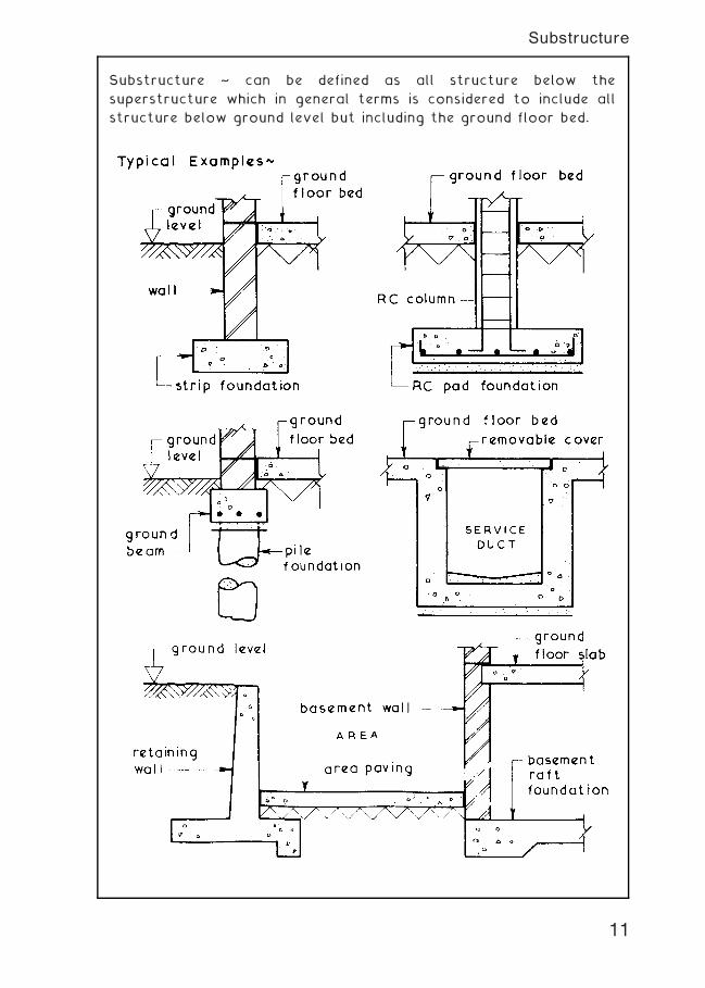
Substructure ~ can be defined as all structure below the
superstructure which in general terms is considered to include all
structure below ground level but including the ground floor bed.
11
Substructure
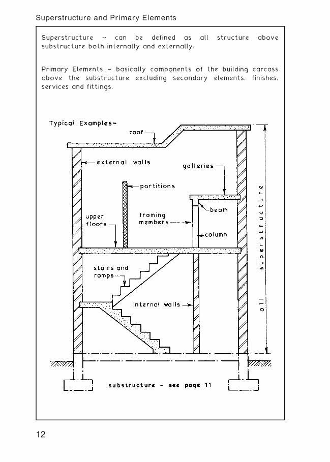
Superstructure ~ can be defined as all structure above
substructure both internally and externally.
Primary Elements ~ basically components of the building carcass
above the substructure excluding secondary elements, finishes,
services and fittings.
12
Superstructure and Primary Elements
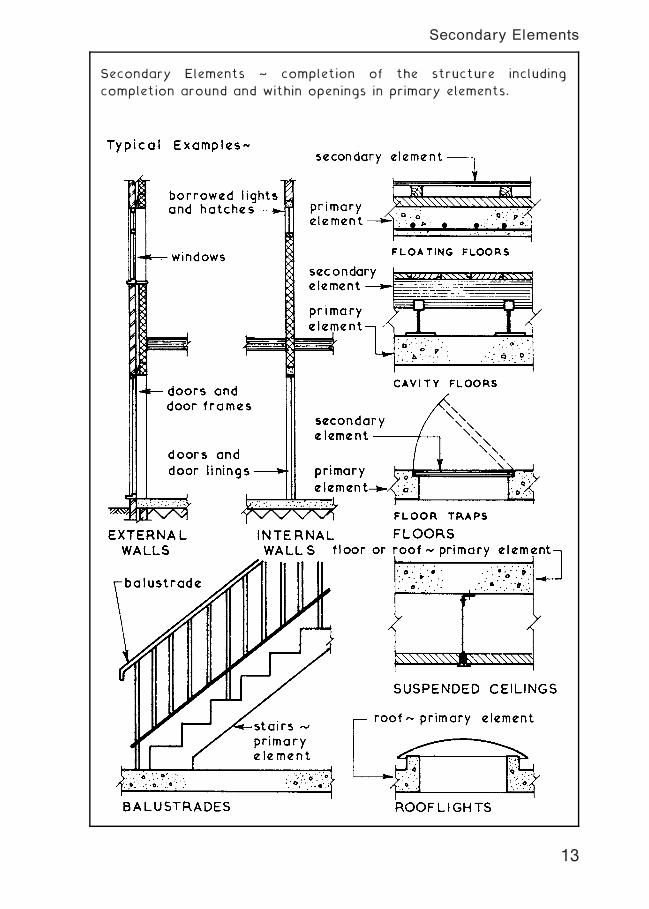
Secondary Elements ~ completion of the structure including
completion around and within openings in primary elements.
13
Secondary Elements
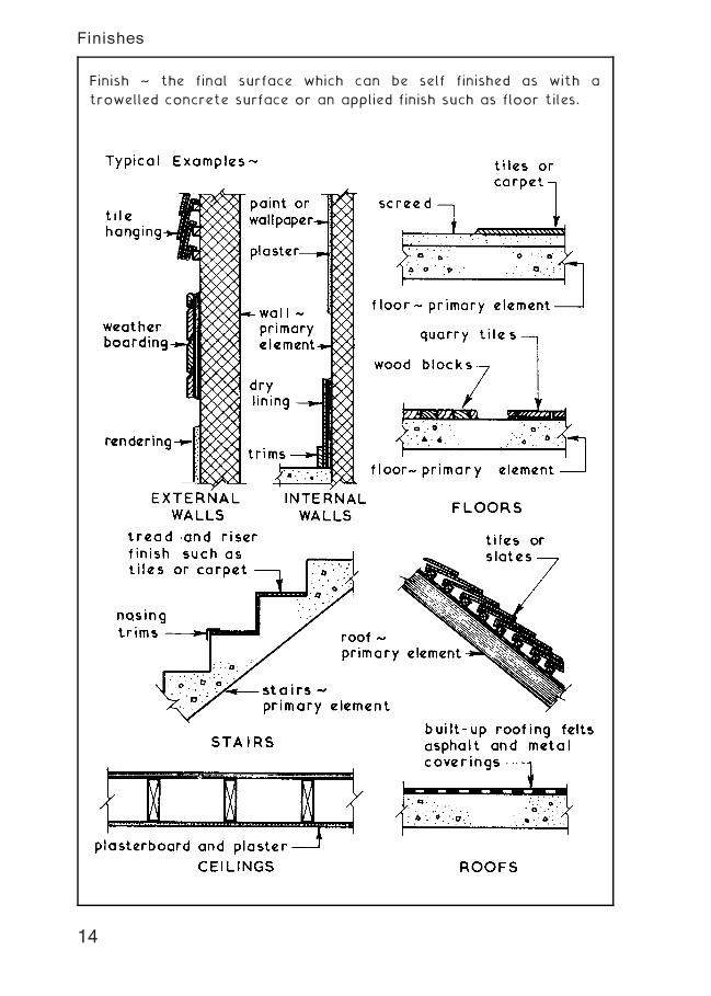
Finish ~ the final surface which can be self finished as with a
trowelled concrete surface or an applied finish such as floor tiles.
14
Finishes
15
Structure---Component Parts and Functions
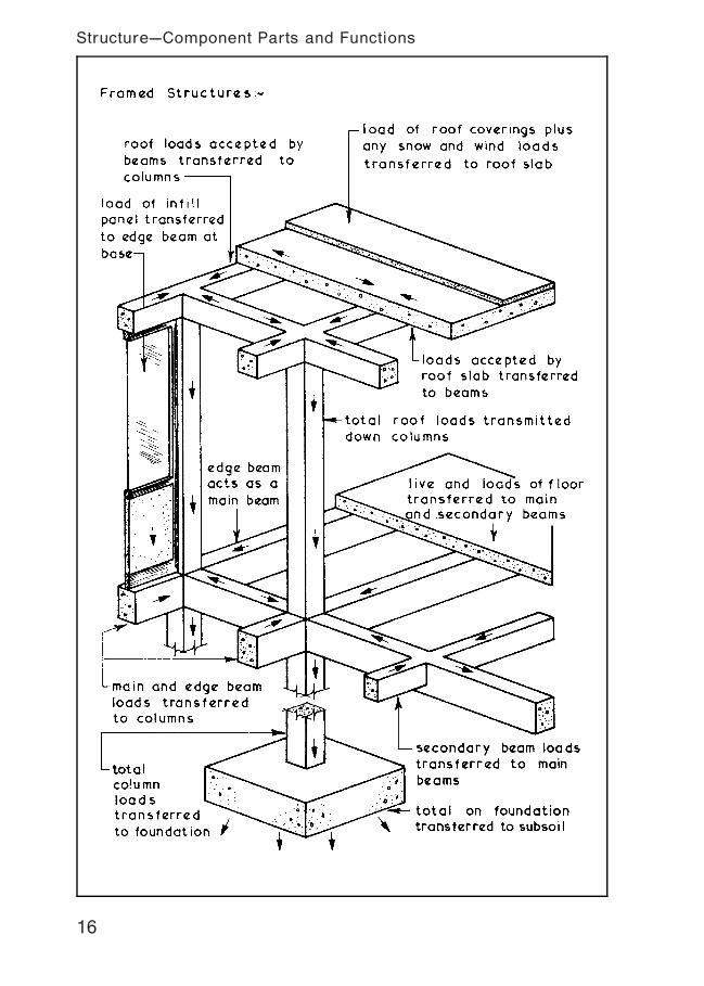
16
Structure---Component Parts and Functions
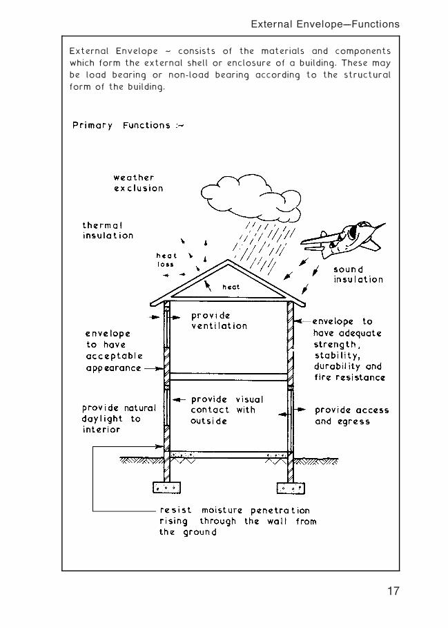
External Envelope ~ consists of the materials and components
which form the external shell or enclosure of a building. These may
be load bearing or non-load bearing according to the structural
form of the building.
17
External Envelope---Functions
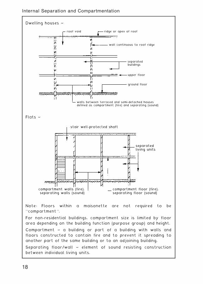
Dwelling houses ~
roof void ridge or apex of roof
wall continuous to roof ridge
separatedbuildings
upper floor
ground floor
walls between terraced and semi-detached housesdefined as compartment (fire) and separating (sound)
Flats ~
stair well-protected shaft
compartment walls (fire),separating walls (sound)
compartment floor (fire),separating floor (sound)
separatedliving units
Note: Floors within a maisonette are not required to be
``compartment''.
For non-residential buildings, compartment size is limited by floor
area depending on the building function (purpose group) and height.
Compartment ~ a building or part of a building with walls and
floors constructed to contain fire and to prevent it spreading to
another part of the same building or to an adjoining building.
Separating floor/wall ~ element of sound resisting construction
between individual living units.
18
Internal Separation and Compartmentation
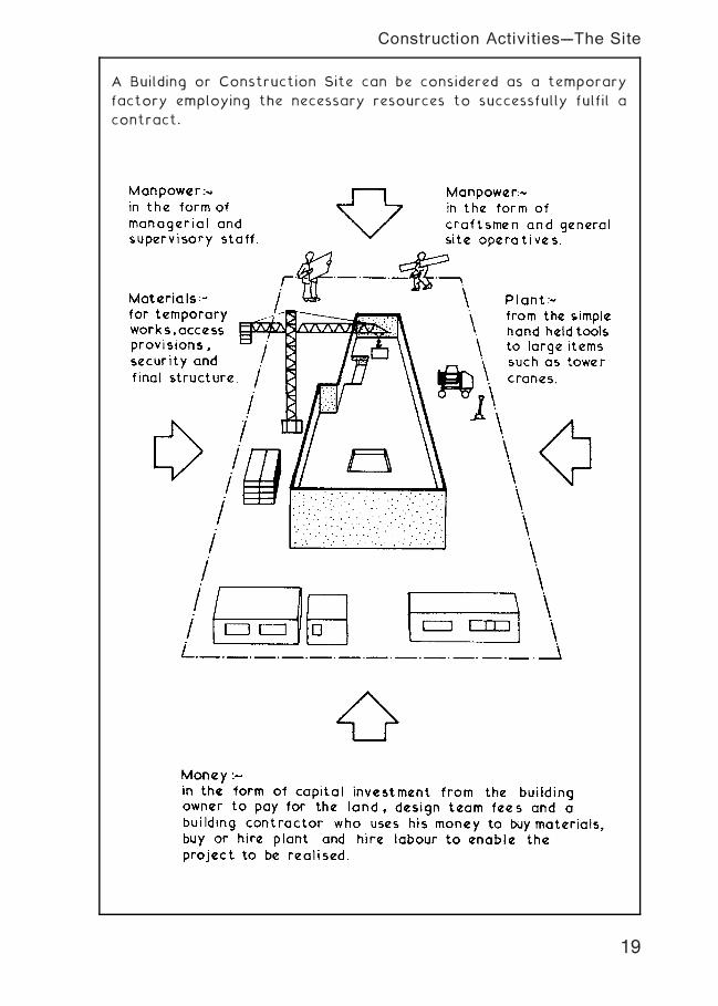
A Building or Construction Site can be considered as a temporary
factory employing the necessary resources to successfully fulfil a
contract.
19
Construction Activities---The Site
20
Construction Activities---The Documents
Location Drawings ~
Site Plans † used to locate site,
buildings, define site levels, indicate
services to buildings, identify parts of
site such as roads, footpaths and
boundaries and to give setting out
dimensions for the site and buildings as
a whole. Suitable scale not less than
1 : 2500
Floor Plans † used to identify and set
out parts of the building such as
rooms, corridors, doors, windows, etc.,
Suitable scale not less than 1 : 100
Elevations † used to show external
appearance of all faces and to identify
doors and windows. Suitable scale not
less than 1 : 100
Sections † used to provide vertical
views through the building to show
method of construction. Suitable scale
not less than 1 : 50
Component Drawings ~
used to identify and supply data for
components to be supplied by a
manufacturer or for components not
completely covered by assembly
drawings. Suitable scale range 1 : 100
to 1 : 1
Assembly Drawings ~
used to show how items fit together or
are assembled to form elements.
Suitable scale range 1 : 20 to 1 : 5
All drawings should be fully annotated,
fully dimensioned and cross referenced.
Ref. BS EN ISO 7519: Technical drawings. Construction drawings.
General principles of presentation for general arrangement and
assembly drawings.
21
Drawings Used in the Construction Process
Sketch ~ this can be defined as a draft or rough outline of an idea,
it can be a means of depicting a three-dimensional form in a
two-dimensional guise. Sketches can be produced free-hand or using
rules and set squares to give basic guide lines.
All sketches should be clear, show all the necessary detail and
above all be in the correct proportions.
Sketches can be drawn by observing a solid object or they can be
produced from conventional orthographic views but in all cases
can usually be successfully drawn by starting with an outline `box'
format giving length, width and height proportions and then
building up the sketch within the outline box.
22
Drawings---Sketches
23
Communicating Information---Orthographic Projections
Isometric Projections ~ a pictorial projection of a solid object on
a plane surface drawn so that all vertical lines remain vertical and
of true scale length, all horizontal lines are drawn at an angle of
30� and are of true scale length therefore scale measurements can
be taken on the vertical and 30� lines but cannot be taken on any
other inclined line.
A similar drawing can be produced using an angle of 45� for all
horizontal lines and is called an Axonometric Projection
ISOMETRIC PROJECTION SHOWING SOUTH AND WEST ELEVATIONS
OF SMALL GARAGE AND WORKSHOP ILLUSTRATED ON PAGE 23
24
Communicating Information---Isometric Projections
25
Communicating Information---Perspective Projections
26
Communicating Information---Floor Plans and Elevations
27
Communicating Information---Block and Site Plans
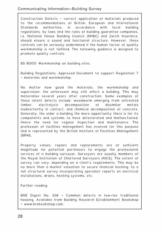
Construction Defects † correct application of materials produced
to the recommendations of British, European and International
Standards authorities, in accordance with local building
regulations, by laws and the rules of building guarantee companies,
i.e. National House Building Council (NHBC) and Zurich Insurance,
should ensure a sound and functional structure. However, these
controls can be seriously undermined if the human factor of quality
workmanship is not fulfilled. The following guidance is designed to
promote quality controls:
BS 8000: Workmanship on building sites.
Building Regulations, Approved Document to support Regulation 7
† materials and workmanship.
No matter how good the materials, the workmanship and
supervision, the unforeseen may still affect a building. This may
materialise several years after construction. Some examples of
these latent defects include: woodworm emerging from untreated
timber, electrolytic decomposition of dissimilar metals
inadvertently in contact, and chemical decomposition of concrete.
Generally, the older a building the more opportunity there is for its
components and systems to have deteriorated and malfunctioned.
Hence the need for regular inspection and maintenance. The
profession of facilities management has evolved for this purpose
and is represented by the British Institute of Facilities Management
(BIFM).
Property values, repairs and replacements are of sufficient
magnitude for potential purchasers to engage the professional
services of a building surveyor. Surveyors are usually members of
the Royal Institution of Chartered Surveyors (RICS). The extent of
survey can vary, depending on a client's requirements. This may be
no more than a market valuation to secure financial backing, to a
full structural survey incorporating specialist reports on electrical
installations, drains, heating systems, etc.
Further reading:
BRE Digest No. 268 † Common defects in low-rise traditional
housing. Available from Building Research Establishment Bookshop
† www.brebookshop.com.
28
Communicating Information---Building Survey
Established Procedure † the interested purchaser engages a
building surveyor.
UK Government Requirements † the seller to provide a property/
home information pack (HIP) which can include `A survey report on
the condition of the property, including requirements for urgent or
significant repairs . . .'.
Survey document preliminaries:
* Title and address of property
* Client's name, address and contacts
* Survey date and time
* Property status † freehold, leasehold or commonhold
* Occupancy † occupied or vacant. If vacant, source of keys
* Extent of survey, e.g. full structural + services reports
* Specialists in attendance, e.g. electrician, heating engineer, etc.
* Age of property (approx. if very dated or no records)
* Disposition of rooms, i.e. number of bedrooms, etc.
* Floor plans and elevations if available
* Elevation (flooding potential) and orientation (solar effect)
* Estate/garden area and disposition if appropriate
* Means of access † roads, pedestrian only, rights of way
Survey tools and equipment:
* Drawings + estate agent's particulars if available
* Notebook and pencil/pen
* Binoculars and a camera with flash facility
* Tape measure, spirit level and plumb line
* Other useful tools, to include small hammer, torch, screwdriver
and manhole lifting irons
* Moisture meter
* Ladders † eaves access and loft access
* Sealable bags for taking samples, e.g. wood rot, asbestos, etc.
29
Communicating Information---Survey Preliminaries
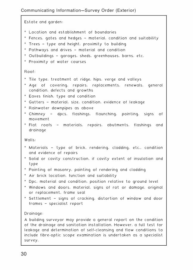
Estate and garden:
* Location and establishment of boundaries
* Fences, gates and hedges † material, condition and suitability
* Trees † type and height, proximity to building
* Pathways and drives † material and condition
* Outbuildings † garages, sheds, greenhouses, barns, etc.
* Proximity of water courses
Roof:
* Tile type, treatment at ridge, hips, verge and valleys
* Age of covering, repairs, replacements, renewals, general
condition, defects and growths
* Eaves finish, type and condition
* Gutters † material, size, condition, evidence of leakage
* Rainwater downpipes as above
* Chimney † dpcs, flashings, flaunching, pointing, signs of
movement
* Flat roofs † materials, repairs, abutments, flashings and
drainage
Walls:
* Materials † type of brick, rendering, cladding, etc., condition
and evidence of repairs
* Solid or cavity construction, if cavity extent of insulation and
type
* Pointing of masonry, painting of rendering and cladding
* Air brick location, function and suitability
* Dpc, material and condition, position relative to ground level
* Windows and doors, material, signs of rot or damage, original
or replacement, frame seal
* Settlement † signs of cracking, distortion of window and door
frames † specialist report
Drainage:
A building surveyor may provide a general report on the condition
of the drainage and sanitation installation. However, a full test for
leakage and determination of self-cleansing and flow conditions to
include fibre-optic scope examination is undertaken as a specialist
survey.
30
Communicating Information---Survey Order (Exterior)
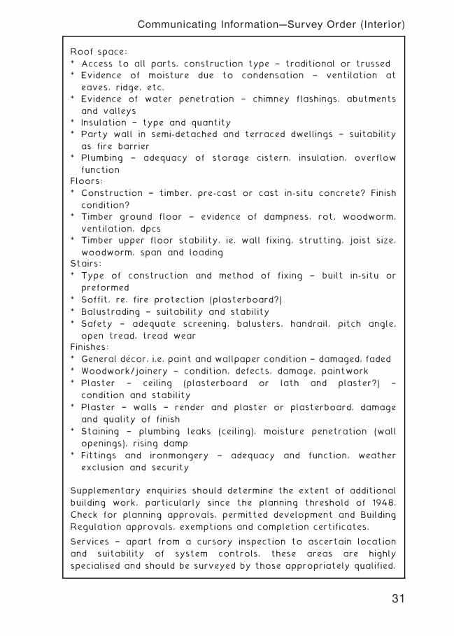
Roof space:
* Access to all parts, construction type † traditional or trussed
* Evidence of moisture due to condensation † ventilation at
eaves, ridge, etc.
* Evidence of water penetration † chimney flashings, abutments
and valleys
* Insulation † type and quantity
* Party wall in semi-detached and terraced dwellings † suitability
as fire barrier
* Plumbing † adequacy of storage cistern, insulation, overflow
function
Floors:
* Construction † timber, pre-cast or cast in-situ concrete? Finish
condition?
* Timber ground floor † evidence of dampness, rot, woodworm,
ventilation, dpcs
* Timber upper floor stability, ie. wall fixing, strutting, joist size,
woodworm, span and loading
Stairs:
* Type of construction and method of fixing † built in-situ or
preformed
* Soffit, re. fire protection (plasterboard?)
* Balustrading † suitability and stability
* Safety † adequate screening, balusters, handrail, pitch angle,
open tread, tread wear
Finishes:
* General de' cor, i.e. paint and wallpaper condition † damaged, faded
* Woodwork/joinery † condition, defects, damage, paintwork
* Plaster † ceiling (plasterboard or lath and plaster?) †
condition and stability
* Plaster † walls † render and plaster or plasterboard, damage
and quality of finish
* Staining † plumbing leaks (ceiling), moisture penetration (wall
openings), rising damp
* Fittings and ironmongery † adequacy and function, weather
exclusion and security
Supplementary enquiries should determine the extent of additional
building work, particularly since the planning threshold of 1948.
Check for planning approvals, permitted development and Building
Regulation approvals, exemptions and completion certificates.
Services † apart from a cursory inspection to ascertain location
and suitability of system controls, these areas are highly
specialised and should be surveyed by those appropriately qualified.
31
Communicating Information---Survey Order (Interior)
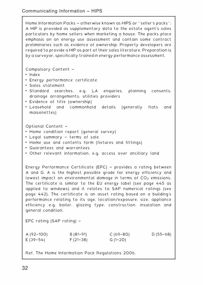
Home Information Packs ~ otherwise known as HIPS or ``seller's packs''.
A HIP is provided as supplementary data to the estate agent's sales
particulars by home sellers when marketing a house. The packs place
emphasis on an energy use assessment and contain some contract
preliminaries such as evidence of ownership. Property developers are
required to provide a HIP as part of their sales literature. Preparation is
by a surveyor, specifically trained in energy performance assessment.
Compulsory Content ~
• Index
• Energy performance certificate
• Sales statement
• Standard searches, e.g. LA enquiries, planning consents,
drainage arrangements, utilities providers
• Evidence of title (ownership)
• Leasehold and commonhold details (generally flats and
maisonettes)
Optional Content ~
• Home condition report (general survey)
• Legal summary † terms of sale
• Home use and contents form (fixtures and fittings)
• Guarantees and warrantees
• Other relevant information, e.g. access over ancillary land
Energy Performance Certificate (EPC) ~ provides a rating between
A and G. A is the highest possible grade for energy efficiency and
lowest impact on environmental damage in terms of CO2 emissions.
The certificate is similar to the EU energy label (see page 445 as
applied to windows) and it relates to SAP numerical ratings (see
page 442). The certificate is an asset rating based on a building's
performance relating to its age, location/exposure, size, appliance
efficiency e.g. boiler, glazing type, construction, insulation and
general condition.
EPC rating (SAP rating) ~
Ref. The Home Information Pack Regulations 2006.
A (92†100) B (81†91) C (69†80) D (55†68)
E (39†54) F (21†38) G (1†20)
32
Communicating Information -- HIPS
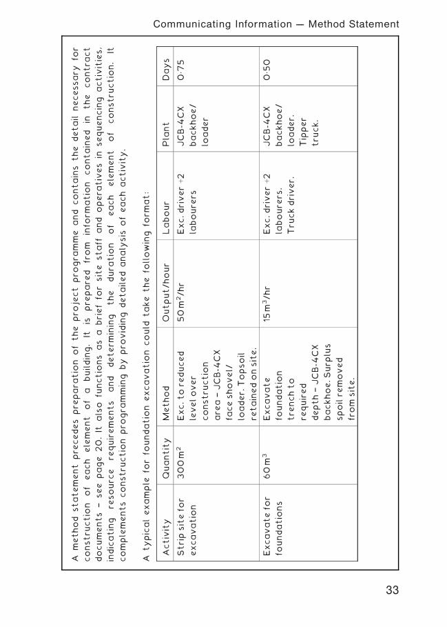
Amethod
statement
pre
cedes
pre
para
tio
nofthe
pro
ject
pro
gra
mme
and
contains
the
detail
necessary
for
constru
ctio
nof
each
element
of
abuilding.
Itis
pre
pare
dfrom
info
rmatio
ncontained
inthe
contra
ct
documents
†see
page
20.It
also
functio
ns
as
abrieffo
rsite
staff
and
opera
tives
insequencing
activities,
indicating
resourc
ere
quirements
and
determ
ining
the
dura
tio
nof
each
element
of
constru
ctio
n.
It
complements
constru
ctio
npro
gra
mming
by
pro
viding
detailed
analy
sis
ofeach
activity.
Atypicalexample
forfo
undatio
nexcavatio
ncould
take
the
following
form
at:
Activity
Quantity
Method
Output/hour
Labour
Pla
nt
Days
Stripsitefo
r
excavatio
n
300m
2Exc.tore
duced
levelover
constru
ctio
n
are
a†JCB-4
CX
faceshovel/
loader.
Topsoil
retainedonsite.
50m
2/hr
Exc.driverþ2
laboure
rs
JCB-4
CX
backhoe/
loader
0„7
5
Excavatefo
r
foundatio
ns
60m
3Excavate
foundatio
n
tre
nchto
required
depth†JCB-4
CX
backhoe.Surp
lus
spoilre
moved
from
site.
15m
3/hr
Exc.driverþ2
laboure
rs.
Tru
ckdriver.
JCB-4
CX
backhoe/
loader.
Tipper
tru
ck.
0„50
33
Communicating Information --- Method Statement
34
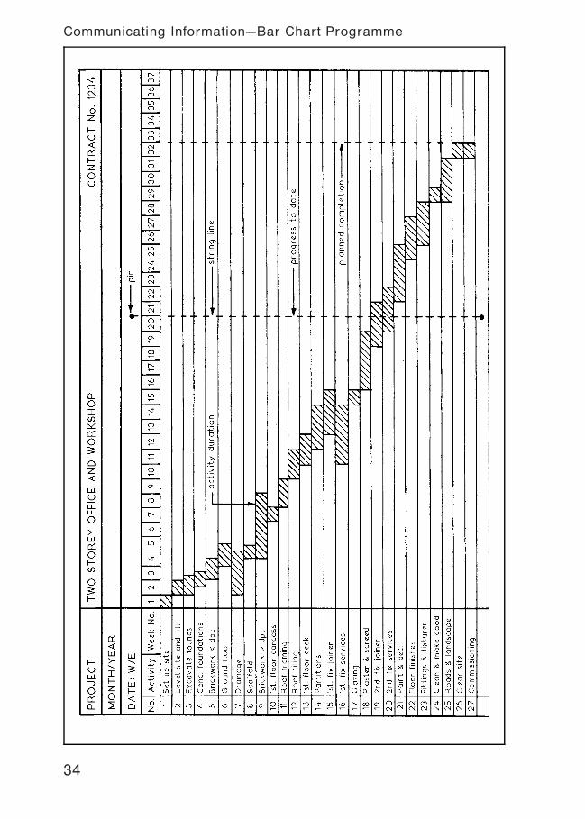
Communicating Information---Bar Chart Programme
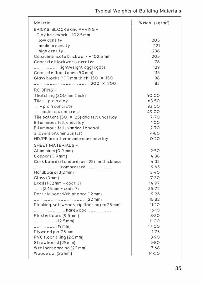
Material Weight (kg/m2)
BRICKS, BLOCKS and PAVING †
Clay brickwork † 102.5mm
low density 205
medium density 221
high density 238
Calcium silicate brickwork † 102.5mm 205
Concrete blockwork, aerated 78
.. .. .. .. .. .. .. .. lightweight aggregate 129
Concrete flagstones (50mm) 115
Glass blocks (100mm thick) 150 � 150 98
.. .. .. .. .. .. .. .. .. .. .. .. .. .. .. .. .. ..200 � 200 83
ROOFING †
Thatching (300mm thick) 40„00
Tiles † plain clay 63„50
.. † plain concrete 93„00
.. single lap, concrete 49„00
Tile battens (50 � 25) and felt underlay 7„70
Bituminous felt underlay 1„00
Bituminous felt, sanded topcoat 2„70
3 layers bituminous felt 4„80
HD/PE breather membrane underlay 0„20
SHEET MATERIALS †
Aluminium (0„9mm) 2„50
Copper (0„9mm) 4„88
Cork board (standard) per 25mm thickness 4„33
.. .. .. .. .. .. .. .. (compressed) .. .. .. .. .. .. .. .. 9„65
Hardboard (3„2mm) 3„40
Glass (3mm) 7„30
Lead (1„32mm † code 3) 14„97
.. .. (3„15mm † code 7) 35„72
Particle board/chipboard (12mm) 9„26
.. .... .... .. .. .. .. .. .. .. .. .. .. .. .. (22mm) 16„82
Planking, softwoodstrip flooring (ex25mm) 11„20
.. .. .. .. .. .. .. .. .. .. hardwood .. .. .. .. .. .. .. .. .. 16„10
Plasterboard (9„5mm) 8„30
.. .. .. .. .. .. .. (12„5mm) 11„00
.. .. .. .. .. .. .. (19mm) 17„00
Plywood per 25mm 1„75
PVC floor tiling (2„5mm) 3„90
Strawboard (25mm) 9„80
Weatherboarding (20mm) 7„68
Woodwool (25mm) 14„50
35
Typical Weights of Building Materials
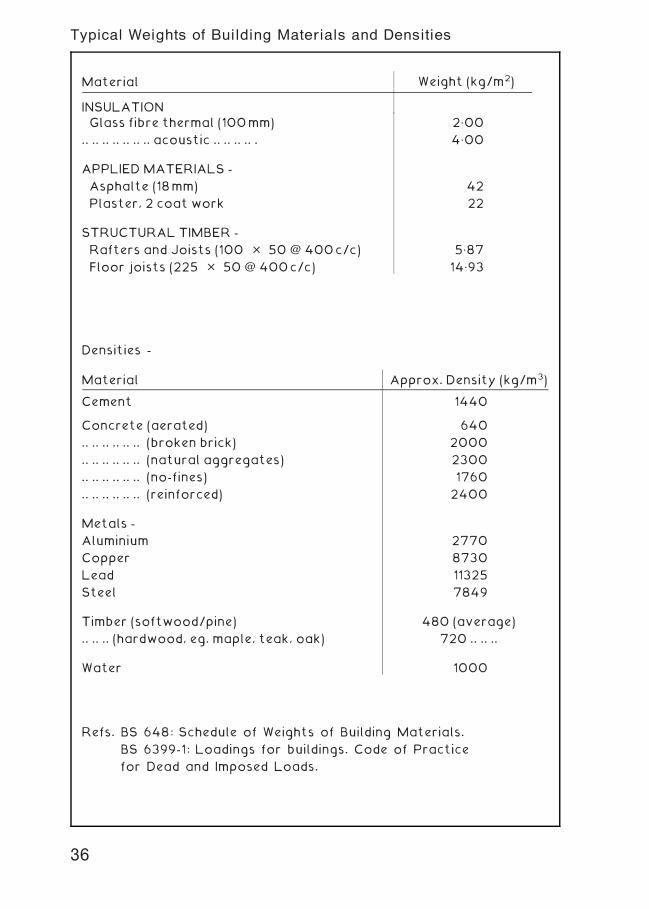
Densities -
Refs. BS 648: Schedule of Weights of Building Materials.
BS 6399-1: Loadings for buildings. Code of Practice
for Dead and Imposed Loads.
Material Approx. Density (kg/m3)
Cement 1440
Concrete (aerated) 640
.. .. .. .. .. .. (broken brick) 2000
.. .. .. .. .. .. (natural aggregates) 2300
.. .. .. .. .. .. (no-fines) 1760
.. .. .. .. .. .. (reinforced) 2400
Metals -
Aluminium 2770
Copper 8730
Lead 11325
Steel 7849
Timber (softwood/pine) 480 (average)
.. .. .. (hardwood, eg. maple, teak, oak) 720 .. .. ..
Water 1000
Material Weight (kg/m2)
INSULATIONGlass fibre thermal (100mm) 2„00
.. .. .. .. .. .. .. acoustic .. .. .. .. . 4„00
APPLIED MATERIALS -
Asphalte (18mm) 42
Plaster, 2 coat work 22
STRUCTURAL TIMBER -
Rafters and Joists (100 � 50 @ 400c/c) 5„87
Floor joists (225 � 50 @ 400c/c) 14„93
36
Typical Weights of Building Materials and Densities
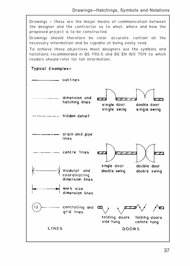
Drawings ~ these are the major means of communication between
the designer and the contractor as to what, where and how the
proposed project is to be constructed.
Drawings should therefore be clear, accurate, contain all the
necessary information and be capable of being easily read.
To achieve these objectives most designers use the symbols and
notations recommended in BS 1192-5 and BS EN ISO 7519 to which
readers should refer for full information.
37
Drawings---Hatchings, Symbols and Notations
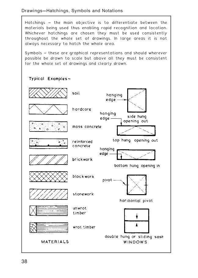
Hatchings ~ the main objective is to differentiate between the
materials being used thus enabling rapid recognition and location.
Whichever hatchings are chosen they must be used consistently
throughout the whole set of drawings. In large areas it is not
always necessary to hatch the whole area.
Symbols ~ these are graphical representations and should wherever
possible be drawn to scale but above all they must be consistent
for the whole set of drawings and clearly drawn.
38
Drawings---Hatchings, Symbols and Notations
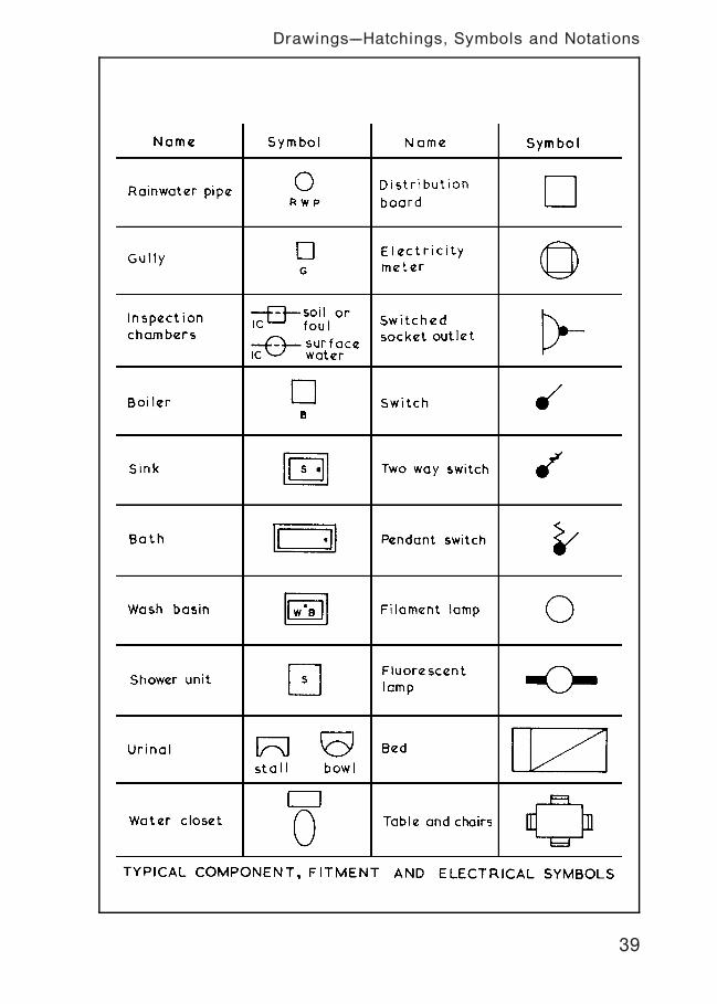
39
Drawings---Hatchings, Symbols and Notations
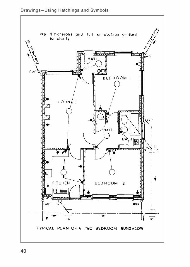
40
Drawings---Using Hatchings and Symbols
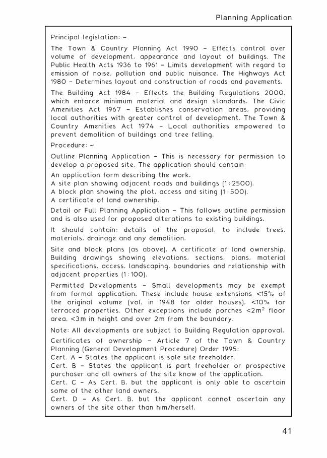
Principal legislation: ~
The Town & Country Planning Act 1990 † Effects control over
volume of development, appearance and layout of buildings. The
Public Health Acts 1936 to 1961 † Limits development with regard to
emission of noise, pollution and public nuisance. The Highways Act
1980 † Determines layout and construction of roads and pavements.
The Building Act 1984 † Effects the Building Regulations 2000,
which enforce minimum material and design standards. The Civic
Amenities Act 1967 † Establishes conservation areas, providing
local authorities with greater control of development. The Town &
Country Amenities Act 1974 † Local authorities empowered to
prevent demolition of buildings and tree felling.
Procedure: ~
Outline Planning Application † This is necessary for permission to
develop a proposed site. The application should contain:
An application form describing the work.
A site plan showing adjacent roads and buildings (1 : 2500).
A block plan showing the plot, access and siting (1 : 500).
A certificate of land ownership.
Detail or Full Planning Application † This follows outline permission
and is also used for proposed alterations to existing buildings.
It should contain: details of the proposal, to include trees,
materials, drainage and any demolition.
Site and block plans (as above). A certificate of land ownership.
Building drawings showing elevations, sections, plans, material
specifications, access, landscaping, boundaries and relationship with
adjacent properties (1 : 100).
Permitted Developments † Small developments may be exempt
from formal application. These include house extensions <15% of
the original volume (vol, in 1948 for older houses), <10% for
terraced properties. Other exceptions include porches <2m2 floor
area, <3m in height and over 2m from the boundary.
Note: All developments are subject to Building Regulation approval.
Certificates of ownership † Article 7 of the Town & Country
Planning (General Development Procedure) Order 1995:
Cert. A † States the applicant is sole site freeholder.
Cert. B † States the applicant is part freeholder or prospective
purchaser and all owners of the site know of the application.
Cert. C † As Cert. B, but the applicant is only able to ascertain
some of the other land owners.
Cert. D † As Cert. B, but the applicant cannot ascertain any
owners of the site other than him/herself.
41
Planning Application
42
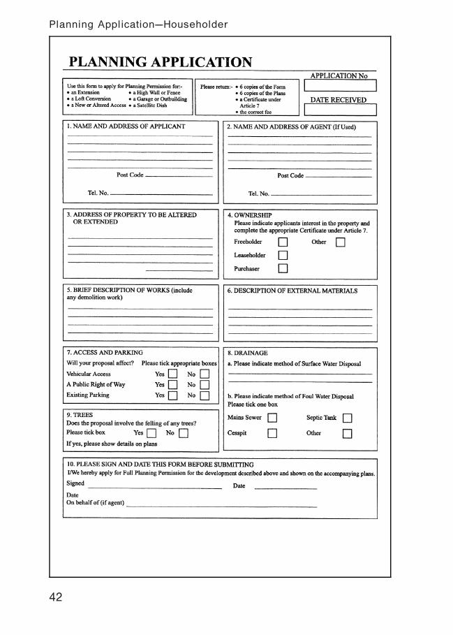
Planning Application---Householder

43
Planning Application---New Build (1)
44
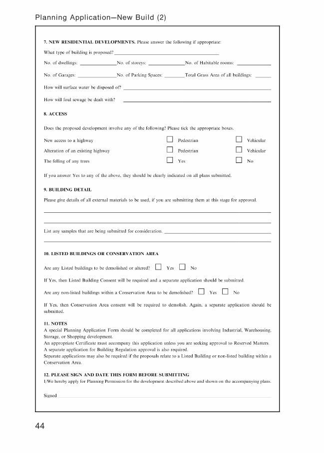
Planning Application---New Build (2)
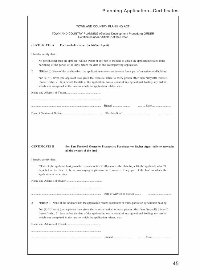
TOWN AND COUNTRY PLANNING ACT
TOWN AND COUNTRY PLANNING (General Development Procedure) ORDERCertificates under Article 7 of the Order
CERTIFICATE A For Freehold Owner (or his/her Agent)
I hereby certify that:-
1. No person other than the applicant was an owner of any part of the land to which the application relates at the
beginning of the period of 21 days before the date of the accompanying application.
2. *Either (i) None of the land to which the application relates constitutes or forms part of an agricultural holding:
*or (ii) *(I have) (the applicant has) given the requisite notice to every person other than *(myself) (himself)
(herself) who, 21 days before the date of the application, was a tenant of any agricultural holding any part of
which was comprised in the land to which the application relates, viz:-
Name and Address of Tenant .................................................
.................................................................................................
................................................................................................. Signed ........................ ........... Date..........................
Date of Service of Notice........................................................ *On Behalf of ....................................... ....................
CERTIFICATE B For Part Freehold Owner or Prospective Purchaser (or his/her Agent) able to ascertainall the owners of the land
I hereby certify that:-
1. *(I have) (the applicant has) given the requisite notice to all persons other than (myself) (the applicant) who, 21
days before the date of the accompanying application were owners of any part of the land to which the
application relates, viz:-
Name and Address of Owner .................................................
.................................................................................................
................................................................................................. Date of Service of Notice ......... ................................
2. *Either (i) None of the land to which the application relates constitutes or forms part of an agricultural holding;
*or (ii) *(I have) (the applicant has) given the requisite notice to every person other than *(myself) (himself)
(herself) who, 21 days before the date of the application, was a tenant of any agricultural holding any part of
which was comprised in the land to which the application relates, viz:-
Name and Address of Tenant .................................................
.................................................................................................
................................................................................................. Signed ........................ .......... Date..........................
45
Planning Application---Certificates
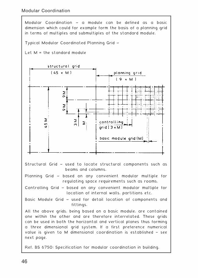
Modular Coordination ~ a module can be defined as a basic
dimension which could for example form the basis of a planning grid
in terms of multiples and submultiples of the standard module.
Typical Modular Coordinated Planning Grid ~
Let M = the standard module
Structural Grid ~ used to locate structural components such as
beams and columns.
Planning Grid ~ based on any convenient modular multiple for
regulating space requirements such as rooms.
Controlling Grid ~ based on any convenient modular multiple for
location of internal walls, partitions etc.
Basic Module Grid ~ used for detail location of components and
fittings.
All the above grids, being based on a basic module, are contained
one within the other and are therefore interrelated. These grids
can be used in both the horizontal and vertical planes thus forming
a three dimensional grid system. If a first preference numerical
value is given to M dimensional coordination is established † see
next page.
Ref. BS 6750: Specification for modular coordination in building.
46
Modular Coordination
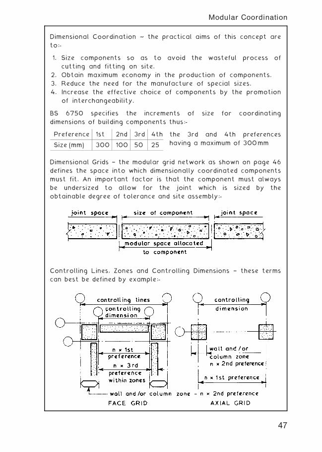
Dimensional Coordination ~ the practical aims of this concept are
to:-
1. Size components so as to avoid the wasteful process of
cutting and fitting on site.
2. Obtain maximum economy in the production of components.
3. Reduce the need for the manufacture of special sizes.
4. Increase the effective choice of components by the promotion
of interchangeability.
BS 6750 specifies the increments of size for coordinating
dimensions of building components thus:-
the 3rd and 4th preferences
having a maximum of 300mm
Dimensional Grids † the modular grid network as shown on page 46
defines the space into which dimensionally coordinated components
must fit. An important factor is that the component must always
be undersized to allow for the joint which is sized by the
obtainable degree of tolerance and site assembly:-
Controlling Lines, Zones and Controlling Dimensions † these terms
can best be defined by example:-
Preference 1st 2nd 3rd 4th
Size (mm) 300 100 50 25
47
Modular Coordination
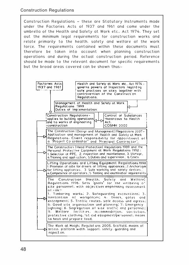
Construction Regulations ~ these are Statutory Instruments made
under the Factories Acts of 1937 and 1961 and come under the
umbrella of the Health and Safety at Work etc., Act 1974. They set
out the minimum legal requirements for construction works and
relate primarily to the health, safety and welfare of the work
force. The requirements contained within these documents must
therefore be taken into account when planning construction
operations and during the actual construction period. Reference
should be made to the relevant document for specific requirements
but the broad areas covered can be shown thus:-
48
Construction Regulations
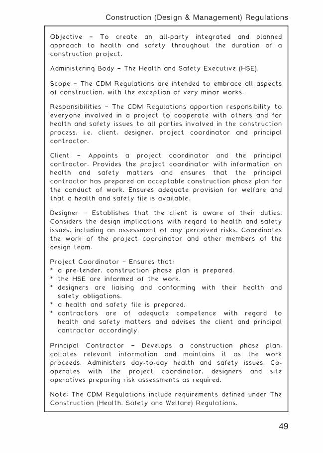
Objective † To create an all-party integrated and planned
approach to health and safety throughout the duration of a
construction project.
Administering Body † The Health and Safety Executive (HSE).
Scope † The CDM Regulations are intended to embrace all aspects
of construction, with the exception of very minor works.
Responsibilities † The CDM Regulations apportion responsibility to
everyone involved in a project to cooperate with others and for
health and safety issues to all parties involved in the construction
process, i.e. client, designer, project coordinator and principal
contractor.
Client † Appoints a project coordinator and the principal
contractor. Provides the project coordinator with information on
health and safety matters and ensures that the principal
contractor has prepared an acceptable construction phase plan for
the conduct of work. Ensures adequate provision for welfare and
that a health and safety file is available.
Designer † Establishes that the client is aware of their duties.
Considers the design implications with regard to health and safety
issues, including an assessment of any perceived risks. Coordinates
the work of the project coordinator and other members of the
design team.
Project Coordinator † Ensures that:
* a pre-tender, construction phase plan is prepared.
* the HSE are informed of the work.
* designers are liaising and conforming with their health and
safety obligations.
* a health and safety file is prepared.
* contractors are of adequate competence with regard to
health and safety matters and advises the client and principal
contractor accordingly.
Principal Contractor † Develops a construction phase plan,
collates relevant information and maintains it as the work
proceeds. Administers day-to-day health and safety issues. Co-
operates with the project coordinator, designers and site
operatives preparing risk assessments as required.
Note: The CDM Regulations include requirements defined under The
Construction (Health, Safety and Welfare) Regulations.
49
Construction (Design & Management) Regulations
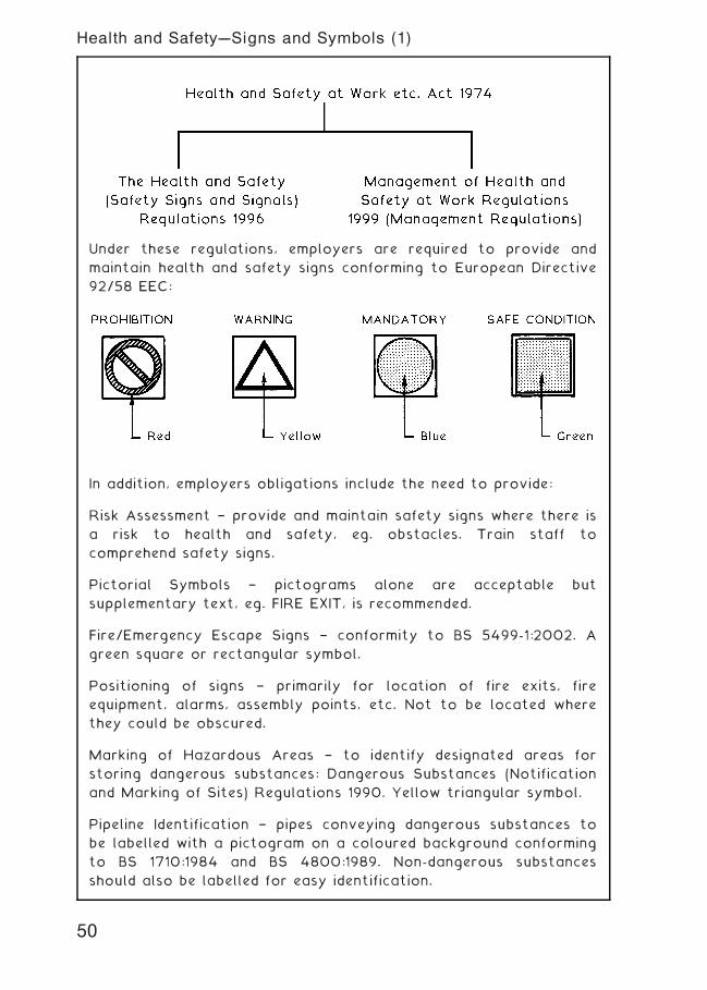
Under these regulations, employers are required to provide and
maintain health and safety signs conforming to European Directive
92/58 EEC:
In addition, employers obligations include the need to provide:
Risk Assessment † provide and maintain safety signs where there is
a risk to health and safety, eg. obstacles. Train staff to
comprehend safety signs.
Pictorial Symbols † pictograms alone are acceptable but
supplementary text, eg. FIRE EXIT, is recommended.
Fire/Emergency Escape Signs † conformity to BS 5499-1:2002. A
green square or rectangular symbol.
Positioning of signs † primarily for location of fire exits, fire
equipment, alarms, assembly points, etc. Not to be located where
they could be obscured.
Marking of Hazardous Areas † to identify designated areas for
storing dangerous substances: Dangerous Substances (Notification
and Marking of Sites) Regulations 1990. Yellow triangular symbol.
Pipeline Identification † pipes conveying dangerous substances to
be labelled with a pictogram on a coloured background conforming
to BS 1710:1984 and BS 4800:1989. Non-dangerous substances
should also be labelled for easy identification.
50
Health and Safety---Signs and Symbols (1)
51
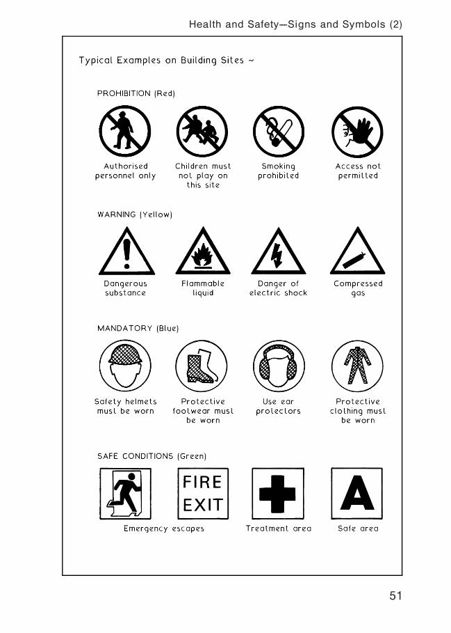
Health and Safety---Signs and Symbols (2)
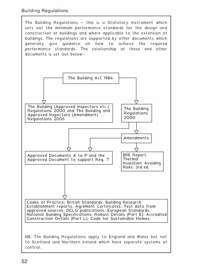
The Building Regulations ~ this is a Statutory Instrument which
sets out the minimum performance standards for the design and
construction of buildings and where applicable to the extension of
buildings. The regulations are supported by other documents which
generally give guidance on how to achieve the required
performance standards. The relationship of these and other
documents is set out below:-
The Building Act 1984
The BuildingRegulations2000
Amendments
BRE Report,ThermalInsulation: AvoidingRisks. 3rd ed.
The Building (Approved Inspectors etc.)Regulations 2000 and The Building andApproved Inspectors (Amendment)Regulations 2006
Approved Documents A to P and theApproved Document to support Reg. 7
Codes of Practice; British Standards; Building ResearchEstablishment reports; Agrement Certificates; Test data fromapproved sources; DCLG publications; European Standards;National Building Specifications; Robust Details (Part E); AccreditedConstruction Details (Part L); Code for Sustainable Homes.
'
NB. The Building Regulations apply to England and Wales but not
to Scotland and Northern Ireland which have separate systems of
control.
52
Building Regulations
Approved Documents ~ these are non-statutory publications
supporting the Building Regulations prepared by the Department
for Communities and Local Government approved by the Secretary
of State and issued by The Stationery Office. The Approved
Documents (ADs) have been compiled to give practical guidance to
comply with the performance standards set out in the various
regulations. They are not mandatory but in the event of a dispute
they will be seen as tending to show compliance with the
requirements of the Building Regulations. If other solutions are
used to satisfy the requirements of the Regulations the burden of
proving compliance rests with the applicant or designer.
Approved Document B — FIRE SAFETY Volume 1 – Dwelling houses Volume 2 – Buildings other than dwelling houses
Approved Document A — STRUCTURE
Approved Document C — SITE PREPARATION AND RESISTANCE TO CONTAMINANTS AND MOISTURE
Approved Document D — TOXIC SUBSTANCES
Approved Document E — RESISTANCE TO THE PASSAGE OF SOUND
Approved Document F — VENTILATION
Approved Document G — HYGIENE
Approved Document H — DRAINAGE AND WASTE DISPOSAL
Approved Document J — COMBUSTION APPLIANCES AND FUEL STORAGE SYSTEMS
Approved Document K — PROTECTION FROM FALLING, COLLISION AND IMPACT
Approved Document L — CONSERVATION OF FUEL AND POWER L1A — New dwellings L1B — Existing dwellings L2A — New buildings other than dwellings L2B — Existing buildings other than dwellings
Approved Document M — ACCESS TO AND USE OF BUILDINGS
Approved Document N — GLAZING — SAFETY IN RELATION TO IMPACT, OPENING AND CLEANING
Approved Document P — ELECTRICAL SAFETY
Approved Document to support Regulation 7 MATERIALS AND WORKMANSHIP
53
Building Regulations
Example in the Use of Approved Documents
Problem:- the sizing of suspended upper floor joists to be spaced
at 400mm centres with a clear span of 3„600m for use
in a two storey domestic dwelling.
Building Regulation A1:- states that the building shall be constructed
so that the combined dead, imposed and wind loads are
sustained and transmitted by it to the ground †
(a) safely, and
(b) without causing such deflection or deformation of
any part of the building, or such movement of the
ground, as will impair the stability of any part of
another building.
Approved Document A:- guidance on sizing floor joists can be
found in `Span Tables for Solid Timber Members in
Dwellings', published by the Timber Research And
Development Association (TRADA), and BS5268-2:
Structural use of timber. Code of practice for
permissible stress design, materials and workmanship.
Dead loading is therefore in the 0„25 to 0„50kN/m2 band
From table on page xxx suitable joist sizes are:- 38 � 200, 50 �175, 63 � 175 and 75 � 150.
Final choice of section to be used will depend upon cost;
availability; practical considerations and/or personal preference.
54
Building Regulations
Building Control ~ unless the applicant has opted for control by a
private approved inspector under The Building (Approved
Inspectors etc.) Regulations 2000 the control of building works in
the context of the Building Regulations is vested in the Local
Authority. There are two systems of control namely the Building
Notice and the Deposit of Plans. The sequence of systems is shown
below:-
Building Notice:-written submission toLA with block plansand drainage detailsfor new work. Notapplicable for non-residential buildingsand most buildingsdesignated under theRegulatory ReformOrder (Fire Safety)
Deposit of Plans:-submission of fullplans and statutoryfee to LA.
If required:- Certificates ofcompliance by anapproved person inthe context of thestructural design andthe conversation ofenergy.
Approval decisionwithin 5 weeks or2 months by mutualagreement.
Notice of rejection.
Appeal to theSecretary of State
Inspections carried out
Work acceptable to LA
Contraventionfound by buildinginspector
Contravention corrected
Section 36 of the Bldg. Act Noticeserved — work to be taken downor altered to comply
Application complies with theSection 36 Notice
Applicant can appeal to a Magistrate's Courtwithin 70 days of a Section 36 Notice beingserved
LA rejectssubmission
Approval which canbe partial orconditional bymutual agreement.
Notification only –approval not required.
Written or other notices to LA :-48 hrs. before commencement24 hrs. before excavations covered before damp course covered before site concrete covered before drains covered7 days after drains completed after work completed and/or before occupation
Applicant contests Notice andsubmits favourable secondopinion to LA.
LA acceptssubmission andwithdrawsSection 36 Notice
NB. In some stages of the above sequence statutory fees are
payable as set out in The Building (Local Authority Charges)
Regulations 1998.
55
Building Regulations
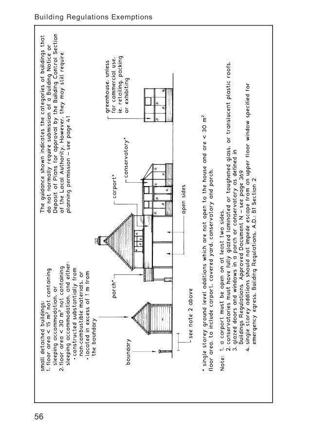
56
Building Regulations Exemptions
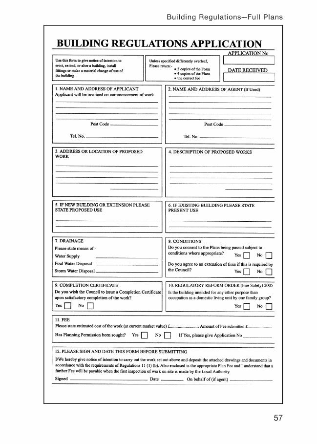
57
Building Regulations---Full Plans
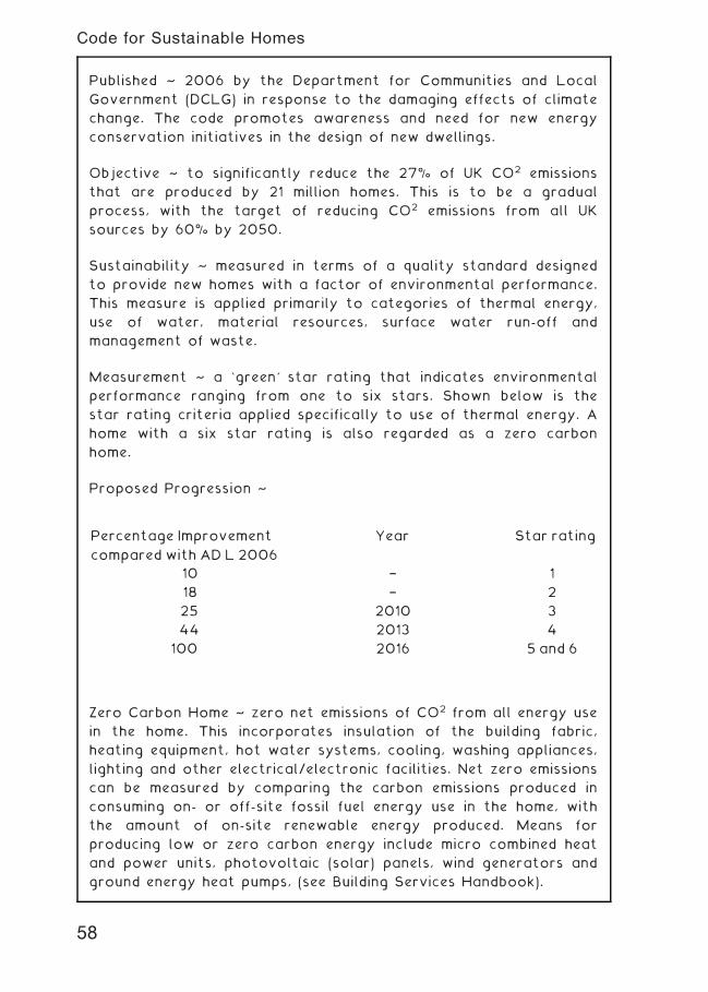
Published ~ 2006 by the Department for Communities and Local
Government (DCLG) in response to the damaging effects of climate
change. The code promotes awareness and need for new energy
conservation initiatives in the design of new dwellings.
Objective ~ to significantly reduce the 27% of UK CO2 emissions
that are produced by 21 million homes. This is to be a gradual
process, with the target of reducing CO2 emissions from all UK
sources by 60% by 2050.
Sustainability ~ measured in terms of a quality standard designed
to provide new homes with a factor of environmental performance.
This measure is applied primarily to categories of thermal energy,
use of water, material resources, surface water run-off and
management of waste.
Measurement ~ a `green' star rating that indicates environmental
performance ranging from one to six stars. Shown below is the
star rating criteria applied specifically to use of thermal energy. A
home with a six star rating is also regarded as a zero carbon
home.
Proposed Progression ~
Zero Carbon Home ~ zero net emissions of CO2 from all energy use
in the home. This incorporates insulation of the building fabric,
heating equipment, hot water systems, cooling, washing appliances,
lighting and other electrical/electronic facilities. Net zero emissions
can be measured by comparing the carbon emissions produced in
consuming on- or off-site fossil fuel energy use in the home, with
the amount of on-site renewable energy produced. Means for
producing low or zero carbon energy include micro combined heat
and power units, photovoltaic (solar) panels, wind generators and
ground energy heat pumps, (see Building Services Handbook).
Percentage Improvement
compared with AD L 2006
Year Star rating
10 † 1
18 † 2
25 2010 3
44 2013 4
100 2016 5 and 6
58
Code for Sustainable Homes
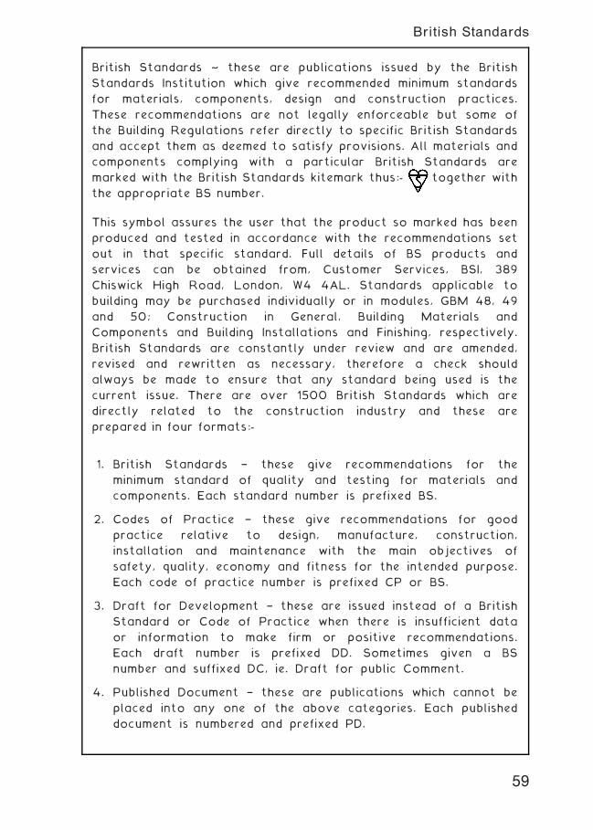
British Standards ~ these are publications issued by the British
Standards Institution which give recommended minimum standards
for materials, components, design and construction practices.
These recommendations are not legally enforceable but some of
the Building Regulations refer directly to specific British Standards
and accept them as deemed to satisfy provisions. All materials and
components complying with a particular British Standards are
marked with the British Standards kitemark thus:- together with
the appropriate BS number.
This symbol assures the user that the product so marked has been
produced and tested in accordance with the recommendations set
out in that specific standard. Full details of BS products and
services can be obtained from, Customer Services, BSI, 389
Chiswick High Road, London, W4 4AL. Standards applicable to
building may be purchased individually or in modules, GBM 48, 49
and 50; Construction in General, Building Materials and
Components and Building Installations and Finishing, respectively.
British Standards are constantly under review and are amended,
revised and rewritten as necessary, therefore a check should
always be made to ensure that any standard being used is the
current issue. There are over 1500 British Standards which are
directly related to the construction industry and these are
prepared in four formats:-
1. British Standards † these give recommendations for the
minimum standard of quality and testing for materials and
components. Each standard number is prefixed BS.
2. Codes of Practice † these give recommendations for good
practice relative to design, manufacture, construction,
installation and maintenance with the main objectives of
safety, quality, economy and fitness for the intended purpose.
Each code of practice number is prefixed CP or BS.
3. Draft for Development † these are issued instead of a British
Standard or Code of Practice when there is insufficient data
or information to make firm or positive recommendations.
Each draft number is prefixed DD. Sometimes given a BS
number and suffixed DC, ie. Draft for public Comment.
4. Published Document † these are publications which cannot be
placed into any one of the above categories. Each published
document is numbered and prefixed PD.
59
British Standards

European Standards † since joining the European Union (EU), trade
and tariff barriers have been lifted. This has opened up the market
for manufacturers of construction-related products, from all EU
and European Economic Area (EEA) member states. Before 2004,
the EU was composed of 15 countries: Austria, Belgium, Denmark,
Finland, France, Germany, Greece, Ireland, Italy, Luxemburg,
Netherlands, Portugal, Spain, Sweden and the United Kingdom. It
now includes Bulgaria, Cyprus, the Czech Republic, Estonia,
Hungary, Latvia, Lithuania, Malta, Poland, Romania, Slovakia and
Slovenia. The EEA extends to: Iceland, Liechtenstein and Norway.
Nevertheless, the wider market is not so easily satisfied, as
regional variations exist. This can create difficulties where product
dimensions and performance standards differ. For example, thermal
insulation standards for masonry walls in Mediterranean regions
need not be the same as those in the UK. Also, preferred
dimensions differ across Europe in items such as bricks, timber, tiles
and pipes.
European Standards are prepared under the auspices of Comite'
Europe'en de Normalisation (CEN), of which the BSI is a member.
European Standards that the BSI have not recognised or adopted,
are prefixed EN. These are EuroNorms and will need revision for
national acceptance.
For the time being, British Standards will continue and where
similarity with other countries' standards and ENs can be identified,
they will run side by side until harmonisation is complete and
approved by CEN.
eg. BS EN 295, complements the previous national standard:
BS 65 † Vitrefied clay pipes . . . . . for drains and sewers.
European Pre-standards are similar to BS Drafts for Development.
These are known as ENVs.
Some products which satisfy the European requirements for safety,
durability and energy efficiency, carry the CE mark. This is not to
be assumed a mark of performance and is not intended to show
equivalence to the BS kitemark. However, the BSI is recognised as
a Notified Body by the EU and as such is authorised to provide
testing and certification in support of the CE mark.
International Standards † these are prepared by the International
Organisation for Standardisation and are prefixed ISO. Many are
compatible with and complement BSs, e.g. the ISO 9000 Quality
Management series and BS 5750: Quality systems.
60
European Standards
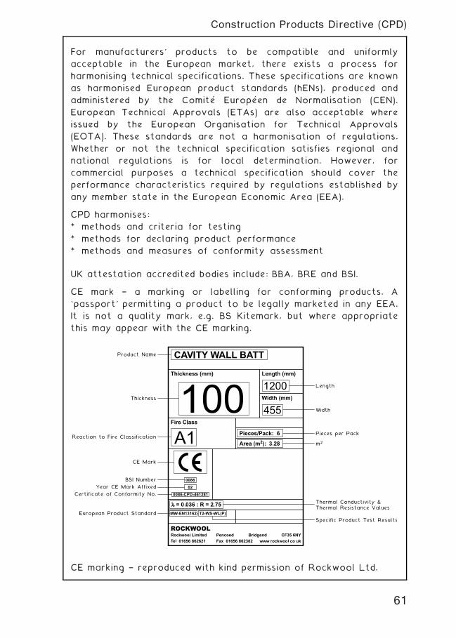
For manufacturers' products to be compatible and uniformly
acceptable in the European market, there exists a process for
harmonising technical specifications. These specifications are known
as harmonised European product standards (hENs), produced and
administered by the Comite' Europe' en de Normalisation (CEN).
European Technical Approvals (ETAs) are also acceptable where
issued by the European Organisation for Technical Approvals
(EOTA). These standards are not a harmonisation of regulations.
Whether or not the technical specification satisfies regional and
national regulations is for local determination. However, for
commercial purposes a technical specification should cover the
performance characteristics required by regulations established by
any member state in the European Economic Area (EEA).
CPD harmonises:
* methods and criteria for testing
* methods for declaring product performance
* methods and measures of conformity assessment
UK attestation accredited bodies include: BBA, BRE and BSI.
CE mark † a marking or labelling for conforming products. A
`passport' permitting a product to be legally marketed in any EEA.
It is not a quality mark, e.g. BS Kitemark, but where appropriate
this may appear with the CE marking.
CE marking † reproduced with kind permission of Rockwool Ltd.
61
Construction Products Directive (CPD)
Building Research Establishment ~ The BRE was founded as a UK
Government agency in 1921 and was known until the early 1970s as
the Building Research Station.
In addition to UK Government funding, some financial support is
now provided by the European Union. Additional funding is derived
from a variety of sources, including commercial services for private
industry and from publications. The latter includes the BRE's well
known regular issue of research information products, i.e. Digests,
Information Papers, Good Building Guides and Good Repair Guides.
UK Government support is principally through the Department of
Trade and Industry (DTI) and the Department for Communities and
Local Government (DCLG). The DCLG works with the BRE in
formulating specific aspects of the Approved Documents to the
Building Regulations. Commissioned research is funded by BRE
Trust.
The BRE incorporates and works with other specialised research
and material testing organisations, e.g. see LPCB, below. It is
accredited under the United Kingdom Accreditation Service (UKAS)
as a testing laboratory authorised to issue approvals and
certifications such as CE product marking (see pages 60 and 61).
Certification of products, materials and applications is effected
through BRE Certification Ltd.
Loss Prevention Certification Board (LPCB) ~ The origins of this
organisation date back to the latter part of the 19th century, when
it was established by a group of building insurers as the Fire
Offices' Committee (FOC).
Through a subdivision known as the Loss Prevention Council
(LPC), the FOC produced a number of technical papers and
specifications relating to standards of building construction and
fire control installations. These became the industry standards
that were, and continue to be, frequently used by building insurers
as supplementary to local byelaws and latterly the Building
Regulation Approved Documents.
In the late 1980s the LPC was renamed as the LPCB as a result of
reorganisation within the insurance profession. At this time the
former LPC guidance documents became established in the current
format of Loss Prevention Standards.
In 2000 the LCPB became part of the BRE and now publishes its
Standards under BRE Certification Ltd.
62
Product and Practice Accreditation
CPI System of Coding ~ the Co-ordinated Project Information
initiative originated in the 1970s in response to the need to
establish a common arrangement of document and language
communication, across the varied trades and professions of the
construction industry.
However, it has only been effective in recent years with the
publication of the Standard Method of Measurement 7th edition
(SMM 7), the National Building Specification (NBS) and the Drawings
Code. (Note: The NBS is also produced in CI/SfB format.)
The arrangement in all documents is a coordination of alphabetic
sections, corresponding to elements of work, the purpose being to
avoid mistakes, omissions and other errors which have in the past
occurred between drawings, specification and bill of quantities
descriptions.
The coding is a combination of letters and numbers, spanning 3
levels:-
Level 1 has 24 headings from A to Z (omitting I and O). Each
heading relates to part of the construction process, such as
groundwork (D), Joinery (L), surface finishes (M), etc.
Level 2 is a sub-heading, which in turn is sub-grouped numerically
into different categories. So for example, Surface Finishes is sub-
headed; Plaster, Screeds, Painting, etc. These sub-headings are then
extended further, thus Plaster becomes; Plastered/Rendered
Coatings, Insulated Finishes, Sprayed Coatings etc.
Level 3 is the work section sub-grouped from level 2, to include a
summary of inclusions and omissions.
As an example, an item of work coded M21 signifies:-
M † Surface finishes
2 † Plastered coatings
1 † Insulation with rendered finish
The coding may be used to:-
(a) simplify specification writing
(b) reduce annotation on drawings
(c) rationalise traditional taking-off methods
63
CPI System of Coding
CI/SfB System ~ this is a coded filing system for the classification
and storing of building information and data. It was created in
Sweden under the title of Samarbetskommitte..n fo
..r Byggnadsfraƒgor
and was introduced into this country in 1961 by the RIBA. In 1968
the CI (Construction Index) was added to the system which is used
nationally and recognised throughout the construction industry.
The system consists of 5 sections called tables which are
subdivided by a series of letters or numbers and these are listed in
the CI/SfB index book to which reference should always be made in
the first instance to enable an item to be correctly filed or
retrieved.
Table 0 † Physical Environment
This table contains ten sections 0 to 9 and deals mainly with the
end product (i.e. the type of building.) Each section can be further
subdivided (e.g. 21, 22, et seq.) as required.
Table 1 † Elements
This table contains ten sections numbered (††) to (9†) and covers all
parts of the structure such as walls, floors and services. Each sec-
tion can be further subdivided (e.g. 31, 32 et seq.) as required.
Table 2 † Construction Form
This table contains twenty five sections lettered A to Z (O being
omitted) and covers construction forms such as excavation work,
blockwork, cast in-situ work etc., and is not subdivided but used in
conjunction with Table 3.
Table 3 † Materials
This table contains twenty five sections lettered a to z (l being
omitted) and covers the actual materials used in the construction
form such as metal, timber, glass etc., and can be subdivided (e.g. n1,
n2 et seq.) as required.
Table 4 † Activities and Requirements
This table contains twenty five sections lettered (A) to (Z), (O being
omitted) and covers anything which results from the building
process such as shape, heat, sound, etc. Each section can be further
subdivided ((M1), (M2) et seq.) as required.
64
CI/SfB System of Coding
2 SITE WORKS
SITE INVESTIGATIONS
SOIL INVESTIGATION
SOIL ASSESSMENT AND TESTING
SITE LAYOUT CONSIDERATIONS
SITE SECURITY
SITE LIGHTING AND ELECTRICAL SUPPLY
SITE OFFICE ACCOMMODATION
MATERIALS STORAGE
MATERIALS TESTING
SETTING OUT
LEVELS AND ANGLES
ROAD CONSTRUCTION
TUBULARSCAFFOLDINGANDSCAFFOLDINGSYSTEMS
SHORING SYSTEMS
DEMOLITION
65
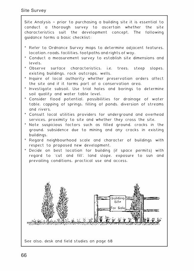
Site Analysis † prior to purchasing a building site it is essential to
conduct a thorough survey to ascertain whether the site
characteristics suit the development concept. The following
guidance forms a basic checklist:
* Refer to Ordnance Survey maps to determine adjacent features,
location, roads, facilities, footpaths and rights of way.
* Conduct a measurement survey to establish site dimensions and
levels.
* Observe surface characteristics, i.e. trees, steep slopes,
existing buildings, rock outcrops, wells.
* Inquire of local authority whether preservation orders affect
the site and if it forms part of a conservation area.
* Investigate subsoil. Use trial holes and borings to determine
soil quality and water table level.
* Consider flood potential, possibilities for drainage of water
table, capping of springs, filling of ponds, diversion of streams
and rivers.
* Consult local utilities providers for underground and overhead
services, proximity to site and whether they cross the site.
* Note suspicious factors such as filled ground, cracks in the
ground, subsidence due to mining and any cracks in existing
buildings.
* Regard neighbourhood scale and character of buildings with
respect to proposed new development.
* Decide on best location for building (if space permits) with
regard to `cut and fill', land slope, exposure to sun and
prevailing conditions, practical use and access.
See also, desk and field studies on page 68
66
Site Survey
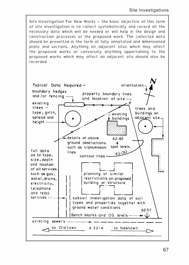
Site Investigation For New Works ~ the basic objective of this form
of site investigation is to collect systematically and record all the
necessary data which will be needed or will help in the design and
construction processes of the proposed work. The collected data
should be presented in the form of fully annotated and dimensioned
plans and sections. Anything on adjacent sites which may affect
the proposed works or conversely anything appertaining to the
proposed works which may affect an adjacent site should also be
recorded.
67
Site Investigations
Procedures ~
1 . Desk study
2. Field study or walk-over survey
3. Laboratory analysis (see pages 77†78 and 81†83)
Desk Study ~ collection of known data, to include:
• Ordnance Survey maps † historical and modern, note grid
reference.
• Geological maps † subsoil types, radon risk.
• Site history † green-field/brown-field.
• Previous planning applications/approvals.
• Current planning applications in the area.
• Development restrictions † conservation orders.
• Utilities † location of services on and near the site.
• Aerial photographs.
• Ecology factors † protected wildlife.
• Local knowledge † anecdotal information/rights of way.
• Proximity of local land fill sites † methane risk.
Field Study ~ intrusive visual and physical activity to:
• Establish site characteristics from the desk study.
• Assess potential hazards to health and safety.
• Appraise surface conditions:
* Trees † preservation orders.
* Topography and geomorphological mapping.
• Appraise ground conditions:
* Water table.
* Flood potential † local water courses and springs.
* Soil types.
* Contamination † vegetation die-back.
* Engineering risks † ground subsidence, mining, old fuel tanks.
* Financial risks † potential for the unforeseen.
• Take subsoil samples and conduct in-situ tests.
• Consider the need for subsoil exploration, trial pits and bore
holes.
• Appraise existing structures:
* Potential for re-use/refurbishment.
* Archaeological value/preservation orders.
* Demolition † costs, health issues e.g. asbestos.
68
Site Investigations
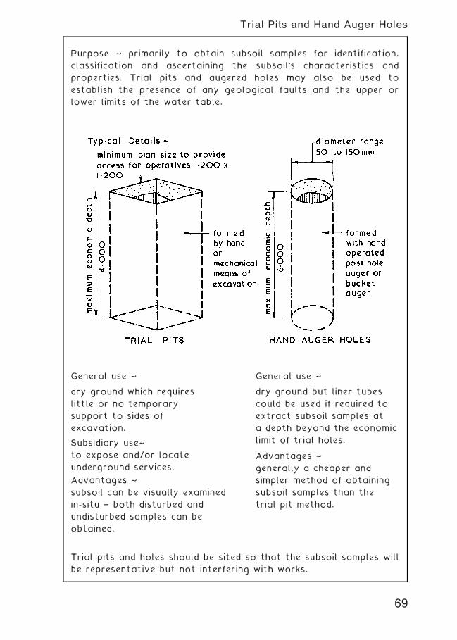
Purpose ~ primarily to obtain subsoil samples for identification,
classification and ascertaining the subsoil's characteristics and
properties. Trial pits and augered holes may also be used to
establish the presence of any geological faults and the upper or
lower limits of the water table.
General use ~
dry ground which requires
little or no temporary
support to sides of
excavation.
Subsidiary use~
to expose and/or locate
underground services.
Advantages ~
subsoil can be visually examined
in-situ † both disturbed and
undisturbed samples can be
obtained.
General use ~
dry ground but liner tubes
could be used if required to
extract subsoil samples at
a depth beyond the economic
limit of trial holes.
Advantages ~
generally a cheaper and
simpler method of obtaining
subsoil samples than the
trial pit method.
Trial pits and holes should be sited so that the subsoil samples will
be representative but not interfering with works.
69
Trial Pits and Hand Auger Holes
Site Investigation ~ this is an all embracing term covering every
aspect of the site under investigation.
Soil Investigation ~ specifically related to the subsoil beneath the
site under investigation and could be part of or separate from the
site investigation.
Purpose of Soil Investigation ~
1 . Determine the suitability of the site for the proposed project.
2. Determine an adequate and economic foundation design.
3. Determine the difficulties which may arise during the construction
process and period.
4. Determine the occurrence and/or cause of all changes in
subsoil conditions.
The above purposes can usually be assessed by establishing the
physical, chemical and general characteristics of the subsoil by
obtaining subsoil samples which should be taken from positions on
the site which are truly representative of the area but are not
taken from the actual position of the proposed foundations. A
series of samples extracted at the intersection points of a 20„000
square grid pattern should be adequate for most cases.
Soil Samples ~ these can be obtained as disturbed or as
undisturbed samples.
Disturbed Soil Samples ~ these are soil samples obtained from
bore holes and trial pits. The method of extraction disturbs the
natural structure of the subsoil but such samples are suitable for
visual grading, establishing the moisture content and some
laboratory tests. Disturbed soil samples should be stored in
labelled airtight jars.
Undisturbed Soil Samples ~ these are soil samples obtained using
coring tools which preserve the natural structure and properties of
the subsoil. The extracted undisturbed soil samples are labelled and
laid in wooden boxes for dispatch to a laboratory for testing. This
method of obtaining soil samples is suitable for rock and clay
subsoils but difficulties can be experienced in trying to obtain
undisturbed soil samples in other types of subsoil.
The test results of soil samples are usually shown on a drawing
which gives the location of each sample and the test results in the
form of a hatched legend or section.
70
Soil Investigation
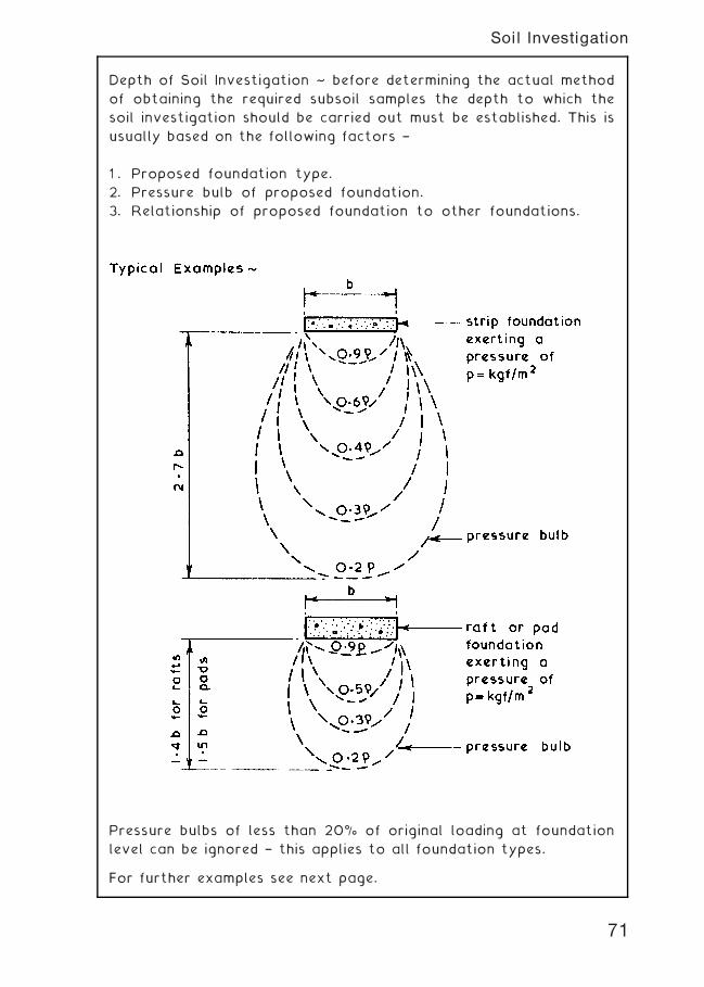
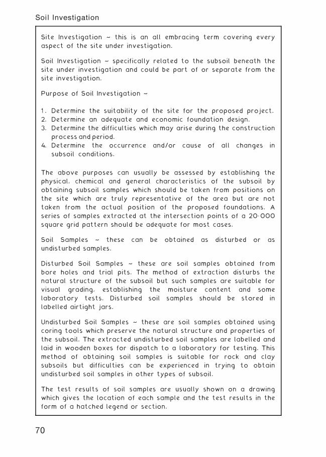
Depth of Soil Investigation ~ before determining the actual method
of obtaining the required subsoil samples the depth to which the
soil investigation should be carried out must be established. This is
usually based on the following factors †
1 . Proposed foundation type.
2. Pressure bulb of proposed foundation.
3. Relationship of proposed foundation to other foundations.
Pressure bulbs of less than 20% of original loading at foundation
level can be ignored † this applies to all foundation types.
For further examples see next page.
71
Soil Investigation
72
Soil Investigation
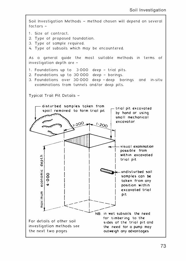
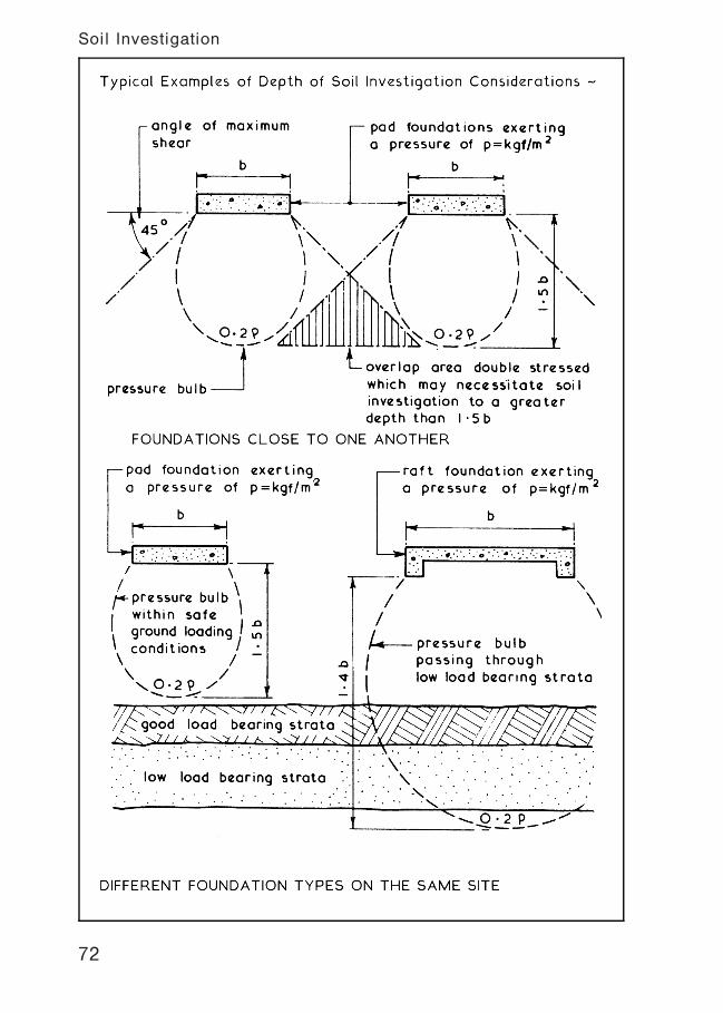
Soil Investigation Methods ~ method chosen will depend on several
factors †
1 . Size of contract.
2. Type of proposed foundation.
3. Type of sample required.
4. Type of subsoils which may be encountered.
As a general guide the most suitable methods in terms of
investigation depth are †
1 . Foundations up to 3�000 deep † trial pits.
2. Foundations up to 30�000 deep † borings.
3. Foundations over 30�000 deep † deep borings and in-situ
examinations from tunnels and/or deep pits.
73
Soil Investigation
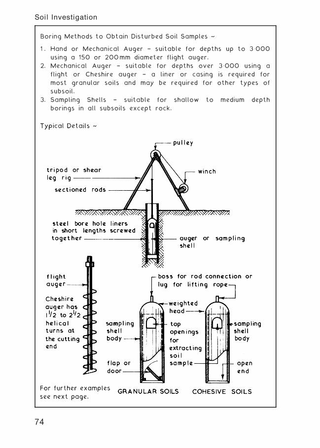
Boring Methods to Obtain Disturbed Soil Samples ~
1 . Hand or Mechanical Auger † suitable for depths up to 3�000
using a 150 or 200mm diameter flight auger.
2. Mechanical Auger † suitable for depths over 3�000 using a
flight or Cheshire auger † a liner or casing is required for
most granular soils and may be required for other types of
subsoil.
3. Sampling Shells † suitable for shallow to medium depth
borings in all subsoils except rock.
74
Soil Investigation
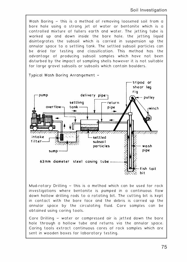
Wash Boring ~ this is a method of removing loosened soil from a
bore hole using a strong jet of water or bentonite which is a
controlled mixture of fullers earth and water. The jetting tube is
worked up and down inside the bore hole, the jetting liquid
disintegrates the subsoil which is carried in suspension up the
annular space to a settling tank. The settled subsoil particles can
be dried for testing and classification. This method has the
advantage of producing subsoil samples which have not been
disturbed by the impact of sampling shells however it is not suitable
for large gravel subsoils or subsoils which contain boulders.
Mud-rotary Drilling ~ this is a method which can be used for rock
investigations where bentonite is pumped in a continuous flow
down hollow drilling rods to a rotating bit. The cutting bit is kept
in contact with the bore face and the debris is carried up the
annular space by the circulating fluid. Core samples can be
obtained using coring tools.
Core Drilling ~ water or compressed air is jetted down the bore
hole through a hollow tube and returns via the annular space.
Coring tools extract continuous cores of rock samples which are
sent in wooden boxes for laboratory testing.
75
Soil Investigation
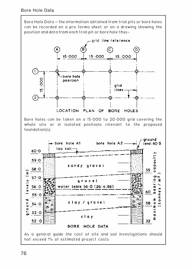
Bore Hole Data ~ the information obtained from trial pits or bore holes
can be recorded on a pro forma sheet or on a drawing showing the
position and data from each trial pit or bore hole thus:-
Bore holes can be taken on a 15„000 to 20„000 grid covering the
whole site or in isolated positions relevant to the proposed
foundation(s)
As a general guide the cost of site and soil investigations should
not exceed 1% of estimated project costs
76
Bore Hole Data
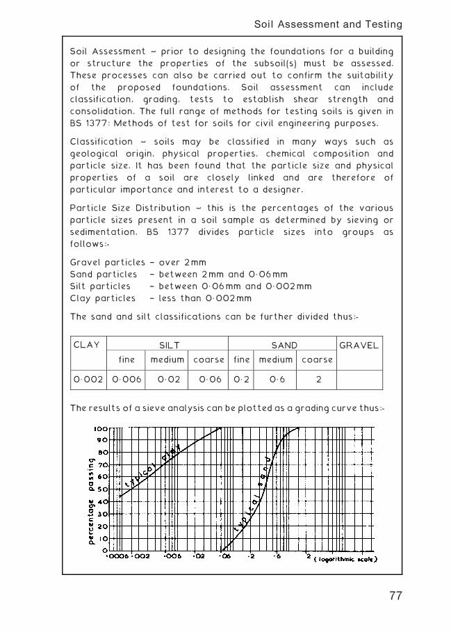
Soil Assessment ~ prior to designing the foundations for a building
or structure the properties of the subsoil(s) must be assessed.
These processes can also be carried out to confirm the suitability
of the proposed foundations. Soil assessment can include
classification, grading, tests to establish shear strength and
consolidation. The full range of methods for testing soils is given in
BS 1377: Methods of test for soils for civil engineering purposes.
Classification ~ soils may be classified in many ways such as
geological origin, physical properties, chemical composition and
particle size. It has been found that the particle size and physical
properties of a soil are closely linked and are therefore of
particular importance and interest to a designer.
Particle Size Distribution ~ this is the percentages of the various
particle sizes present in a soil sample as determined by sieving or
sedimentation. BS 1377 divides particle sizes into groups as
follows:-
Gravel particles † over 2mm
Sand particles † between 2mm and 0„06mm
Silt particles † between 0„06mm and 0„002mm
Clay particles † less than 0„002mm
The sand and silt classifications can be further divided thus:-
The results of a sieve analysis can be plotted as a grading curve thus:-
CLAY SILT SAND GRAVEL
fine medium coarse fine medium coarse
0„002 0„006 0„02 0„06 0„2 0„6 2
77
Soil Assessment and Testing
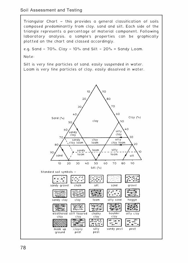
Triangular Chart ~ this provides a general classification of soils
composed predominantly from clay, sand and silt. Each side of the
triangle represents a percentage of material component. Following
laboratory analysis, a sample's properties can be graphically
plotted on the chart and classed accordingly.
e.g. Sand † 70%. Clay † 10% and Silt † 20% = Sandy Loam.
Note:
Silt is very fine particles of sand, easily suspended in water.
Loam is very fine particles of clay, easily dissolved in water.
78
Soil Assessment and Testing
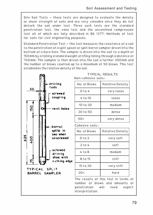
Site Soil Tests ~ these tests are designed to evaluate the density
or shear strength of soils and are very valuable since they do not
disturb the soil under test. Three such tests are the standard
penetration test, the vane test and the unconfined compression
test all of which are fully described in BS 1377; Methods of test
for soils for civil engineering purposes.
Standard Penetration Test ~ this test measures the resistance of a soil
to the penetration of a split spoonor split barrel sampler driven into the
bottom of a bore hole. The sampler is driven into the soil to a depth of
150mmbya falling standardweight of 65kg falling through a distance of
760mm. The sampler is then driven into the soil a further 300mm and
the number of blows counted up to a maximum of 50 blows. This test
establishes the relative density of the soil.
TYPICAL RESULTS
Non-cohesive soils:-
Cohesive soils:-
The results of this test in terms of
number of blows and amounts of
penetration will need expert
interpretation.
No. of Blows Relative Density
0 to 4 very loose
4 to 10 loose
10 to 30 medium
30 to 50 dense
50+ very dense
No. of Blows Relative Density
0 to 2 very soft
2 to 4 soft
4 to 8 medium
8 to 15 stiff
15 to 30 very stiff
30+ hard
79
Soil Assessment and Testing
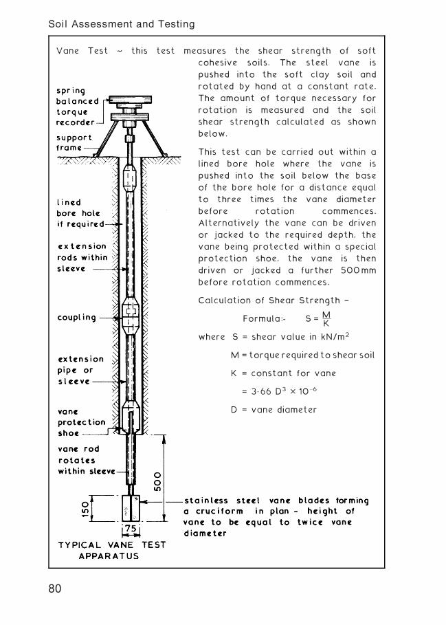
Vane Test ~ this test measures the shear strength of soft
cohesive soils. The steel vane is
pushed into the soft clay soil and
rotated by hand at a constant rate.
The amount of torque necessary for
rotation is measured and the soil
shear strength calculated as shown
below.
This test can be carried out within a
lined bore hole where the vane is
pushed into the soil below the base
of the bore hole for a distance equal
to three times the vane diameter
before rotation commences.
Alternatively the vane can be driven
or jacked to the required depth, the
vane being protected within a special
protection shoe, the vane is then
driven or jacked a further 500mm
before rotation commences.
Calculation of Shear Strength †
Formula:- S = MK
where S = shear value in kN/m2
M = torque required to shear soil
K = constant for vane
= 3„66 D3 � 10�6
D = vane diameter
80
Soil Assessment and Testing
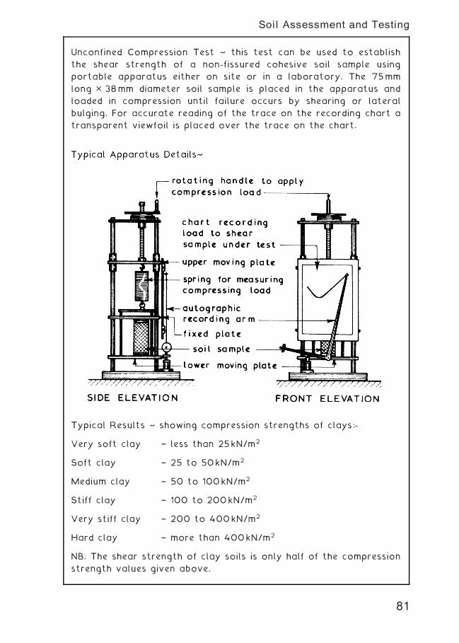
Unconfined Compression Test ~ this test can be used to establish
the shear strength of a non-fissured cohesive soil sample using
portable apparatus either on site or in a laboratory. The 75mm
long � 38mm diameter soil sample is placed in the apparatus and
loaded in compression until failure occurs by shearing or lateral
bulging. For accurate reading of the trace on the recording chart a
transparent viewfoil is placed over the trace on the chart.
Typical Results ~ showing compression strengths of clays:-
Very soft clay † less than 25kN/m2
Soft clay † 25 to 50kN/m2
Medium clay † 50 to 100kN/m2
Stiff clay † 100 to 200kN/m2
Very stiff clay † 200 to 400kN/m2
Hard clay † more than 400kN/m2
NB. The shear strength of clay soils is only half of the compression
strength values given above.
81
Soil Assessment and Testing
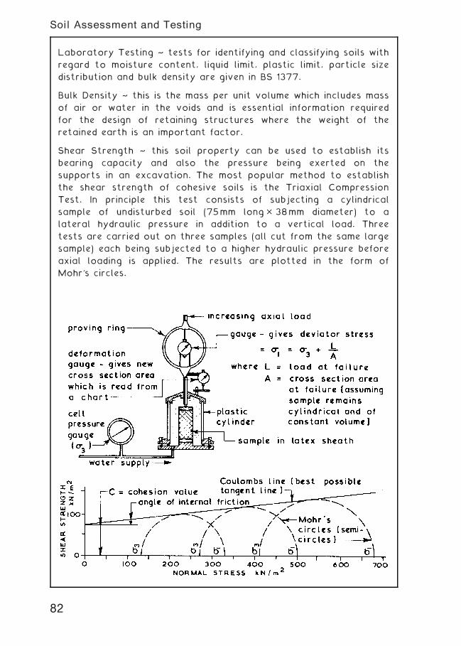
Laboratory Testing ~ tests for identifying and classifying soils with
regard to moisture content, liquid limit, plastic limit, particle size
distribution and bulk density are given in BS 1377.
Bulk Density ~ this is the mass per unit volume which includes mass
of air or water in the voids and is essential information required
for the design of retaining structures where the weight of the
retained earth is an important factor.
Shear Strength ~ this soil property can be used to establish its
bearing capacity and also the pressure being exerted on the
supports in an excavation. The most popular method to establish
the shear strength of cohesive soils is the Triaxial Compression
Test. In principle this test consists of subjecting a cylindrical
sample of undisturbed soil (75mm long� 38mm diameter) to a
lateral hydraulic pressure in addition to a vertical load. Three
tests are carried out on three samples (all cut from the same large
sample) each being subjected to a higher hydraulic pressure before
axial loading is applied. The results are plotted in the form of
Mohr's circles.
82
Soil Assessment and Testing
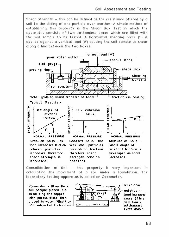
Shear Strength ~ this can be defined as the resistance offered by a
soil to the sliding of one particle over another. A simple method of
establishing this property is the Shear Box Test in which the
apparatus consists of two bottomless boxes which are filled with
the soil sample to be tested. A horizontal shearing force (S) is
applied against a vertical load (W) causing the soil sample to shear
along a line between the two boxes.
Consolidation of Soil ~ this property is very important in
calculating the movement of a soil under a foundation. The
laboratory testing apparatus is called an Oedometer.
83
Soil Assessment and Testing
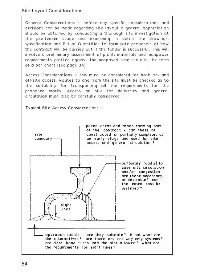
General Considerations ~ before any specific considerations and
decisions can be made regarding site layout a general appreciation
should be obtained by conducting a thorough site investigation at
the pre-tender stage and examining in detail the drawings,
specification and Bill of Quantities to formulate proposals of how
the contract will be carried out if the tender is successful. This will
involve a preliminary assessment of plant, materials and manpower
requirements plotted against the proposed time scale in the form
of a bar chart (see page 34).
Access Considerations ~ this must be considered for both on- and
off-site access. Routes to and from the site must be checked as to
the suitability for transporting all the requirements for the
proposed works. Access on site for deliveries and general
circulation must also be carefully considered.
84
Site Layout Considerations
Storage Considerations ~ amount and types of material to be
stored, security and weather protection requirements, allocation of
adequate areas for storing materials and allocating adequate
working space around storage areas as required, siting of storage
areas to reduce double handling to a minimum without impeding the
general site circulation and/or works in progress.
Accommodation Considerations ~ number and type of site staff
anticipated, calculate size and select units of accommodation and
check to ensure compliance with the minimum requirements of the
Construction (Health, Safety and Welfare) Regulations 1996, select
siting for offices to give easy and quick access for visitors but at
the same time giving a reasonable view of the site, select siting for
messroom and toilets to reduce walking time to a minimum without
impeding the general site circulation and/or works in progress.
Temporary Services Considerations ~ what, when and where are
they required? Possibility of having permanent services installed at
an early stage and making temporary connections for site use
during the construction period, coordination with the various
service undertakings is essential.
Plant Considerations ~ what plant, when and where is it required?
static or mobile plant? If static select the most appropriate
position and provide any necessary hard standing, if mobile check
on circulation routes for optimum efficiency and suitability,
provision of space and hard standing for on-site plant maintenance
if required.
Fencing and Hoarding Considerations ~ what is mandatory and
what is desirable? Local vandalism record, type or types of fence
and/or hoarding required, possibility of using fencing which is part
of the contract by erecting this at an early stage in the contract.
Safety and Health Considerations ~ check to ensure that all the
above conclusions from the considerations comply with the
minimum requirements set out in the various Construction
Regulations and in the Health and Safety at Work etc., Act 1974.
For a typical site layout example see next page.
85
Site Layout Considerations
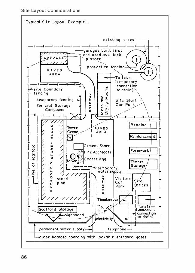
86
Site Layout Considerations
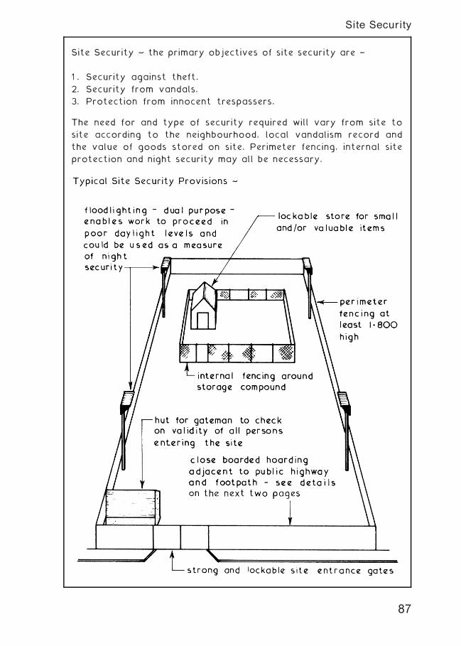
Site Security ~ the primary objectives of site security are †
1 . Security against theft.
2. Security from vandals.
3. Protection from innocent trespassers.
The need for and type of security required will vary from site to
site according to the neighbourhood, local vandalism record and
the value of goods stored on site. Perimeter fencing, internal site
protection and night security may all be necessary.
87
Site Security
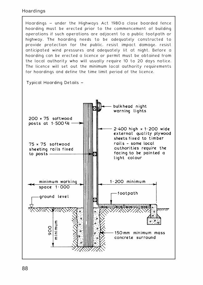
Hoardings ~ under the Highways Act 1980a close boarded fence
hoarding must be erected prior to the commencement of building
operations if such operations are adjacent to a public footpath or
highway. The hoarding needs to be adequately constructed to
provide protection for the public, resist impact damage, resist
anticipated wind pressures and adequately lit at night. Before a
hoarding can be erected a licence or permit must be obtained from
the local authority who will usually require 10 to 20 days notice.
The licence will set out the minimum local authority requirements
for hoardings and define the time limit period of the licence.
88
Hoardings
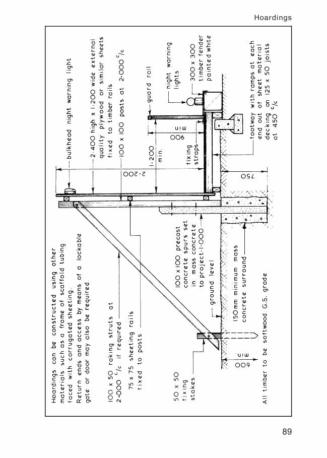
89
Hoardings
Site Lighting ~ this can be used effectively to enable work to continue
during periods of inadequate daylight. It can also be used as a deterrent
to would-be trespassers. Site lighting can be employed externally to
illuminate the storage and circulation areas and internally for general
movement and for specific work tasks. The types of lamp available
range from simple tungsten filament lamps to tungsten halogen and
discharge lamps. The arrangement of site lighting can be static where
the lamps are fixed to support poles or mounted on items of fixed plant
such as scaffolding and tower cranes. Alternatively the lamps can be
sited locally where the work is in progress by being mounted on a
movable support or hand held with a trailing lead. Whenever the
position of site lighting is such that it can be manhandled it should be
run on a reduced voltage of 110V single phase as opposed to the mains
voltage of 230V.
To plan an adequate system of site lighting the types of activity
must be defined and given an illumination target value which is
quoted in lux (lx). Recommended minimum target values for building
activities are:-
Such target values do not take into account deterioration, dirt or
abnormal conditions therefore it is usual to plan for at least twice
the recommended target values. Generally the manufacturers will
provide guidance as to the best arrangement to use in any
particular situation but lamp requirements can be calculated thus:-
Total lumensrequired
=area to be illluminated (m2) � target value (lx)
utilisation factor 0„23 [dispersive lights 0„27]
After choosing lamp type to be used:-
Numberoflamps required
=total lumens required
lumen output of chosen lamp
90
Site Lighting
Typical Site Lighting Arrangement:-
Typical minimum heights for dispersive lamps:
Fluorescent40to 125W†2„500m;Tungsten filament300W†3„000m
91
Site Lighting
Walkway and Local Lighting ~ to illuminate the general circulation
routes bulkhead and/or festoon lighting could be used either on a
standard mains voltage of 230V or on a reduced voltage of 110V.
For local lighting at the place of work hand lamps with trailing
leads or lamp fittings on stands can be used and positioned to give
the maximum amount of illumination without unacceptable shadow
cast.
92
Site Lighting
Electrical Supply to Building Sites ~ a supply of electricity is usually
required at an early stage in the contract to provide light and power to
the units of accommodation. As the work progresses power could also
be required for site lighting, hand held power tools and large items of
plant. The supply of electricity to a building site is the subject of a
contract between the contractor and the local area electricity
company who will want to know the date when supply is required; site
address together with a block plan of the site; final load demand of
proposed building and an estimate of the maximum load demand in
kilowatts for the construction period. The latter can be estimated by
allowing 10W/m2 of the total floor area of the proposed building plus
an allowance for high load equipment such as cranes. The installation
should be undertaken by a competent electrical contractor to ensure
that it complies with all the statutory rules and regulations for the
supply of electricity to building sites.
The units must be strong, durable and resistant to rain penetration
with adequate weather seals to all access panels and doors. All
plug and socket outlets should be colour coded :- 400V † red;
230V † blue; 110V † yellow
93
Electrical Supply to Building Sites
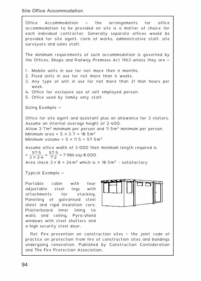
Office Accommodation ~ the arrangements for office
accommodation to be provided on site is a matter of choice for
each individual contractor. Generally separate offices would be
provided for site agent, clerk of works, administrative staff, site
surveyors and sales staff.
The minimum requirements of such accommodation is governed by
the Offices, Shops and Railway Premises Act 1963 unless they are ~
1 . Mobile units in use for not more then 6 months.
2. Fixed units in use for not more than 6 weeks.
3. Any type of unit in use for not more than 21 man hours per
week.
4. Office for exclusive use of self employed person.
5. Office used by family only staff.
Sizing Example ~
Office for site agent and assistant plus an allowance for 3 visitors.
Assume an internal average height of 2„400.
Allow 3„7m2 minimum per person and 11„5m3 minimum per person.
Minimum area = 5 � 3„7 = 18„5m2
Minimum volume = 5 � 11„5 = 57„5m3
Assume office width of 3„000 then minimum length required is
=57„5
3 � 2„4=
57„57„2
= 7„986 say 8„000
Area check 3� 8 = 24m2 which is > 18„5m2 \ satisfactory
Typical Example ~
Portable cabin with four
adjustable steel legs with
attachments for stacking.
Panelling of galvanised steel
sheet and rigid insulation core.
Plasterboard inner lining to
walls and ceiling. Pyro-shield
windows with steel shutters and
a high security steel door.
Ref. Fire prevention on construction sites † the joint code of
practice on protection from fire of construction sites and buildings
undergoing renovation. Published by Construction Confederation
and The Fire Protection Association.
94
Site Office Accommodation
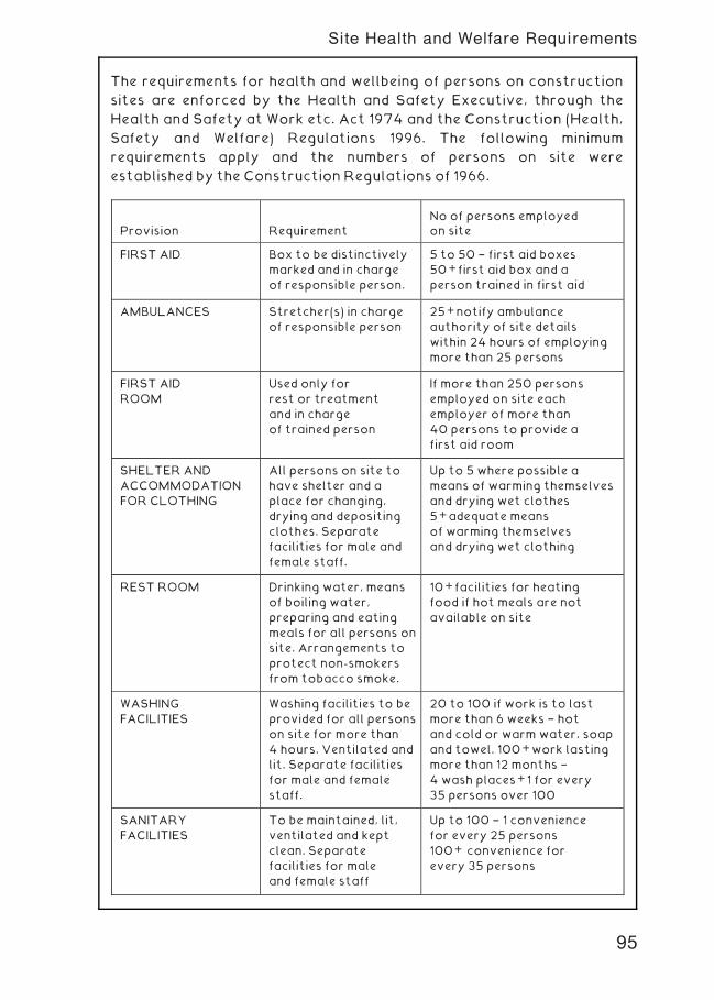
The requirements for health and wellbeing of persons on construction
sites are enforced by the Health and Safety Executive, through the
Health and Safety at Work etc. Act 1974 and the Construction (Health,
Safety and Welfare) Regulations 1996. The following minimum
requirements apply and the numbers of persons on site were
established by the Construction Regulations of 1966.
Provision RequirementNo of persons employedon site
FIRST AID Box to be distinctively
marked and in charge
of responsible person.
5 to 50 † first aid boxes
50+first aid box and a
person trained in first aid
AMBULANCES Stretcher(s) in charge
of responsible person
25+notify ambulance
authority of site details
within 24 hours of employing
more than 25 persons
FIRST AID
ROOM
Used only for
rest or treatment
and in charge
of trained person
If more than 250 persons
employed on site each
employer of more than
40 persons to provide a
first aid room
SHELTER AND
ACCOMMODATION
FOR CLOTHING
All persons on site to
have shelter and a
place for changing,
drying and depositing
clothes. Separate
facilities for male and
female staff.
Up to 5 where possible a
means of warming themselves
and drying wet clothes
5+adequate means
of warming themselves
and drying wet clothing
REST ROOM Drinking water, means
of boiling water,
preparing and eating
meals for all persons on
site. Arrangements to
protect non-smokers
from tobacco smoke.
10+facilities for heating
food if hot meals are not
available on site
WASHING
FACILITIES
Washing facilities to be
provided for all persons
on site for more than
4 hours. Ventilated and
lit. Separate facilities
for male and female
staff.
20 to 100 if work is to last
more than 6 weeks † hot
and cold or warm water, soap
and towel. 100+work lasting
more than 12 months †
4 wash places+1 for every
35 persons over 100
SANITARY
FACILITIES
To be maintained, lit,
ventilated and kept
clean. Separate
facilities for male
and female staff
Up to 100 † 1 convenience
for every 25 persons
100+ convenience for
every 35 persons
95
Site Health and Welfare Requirements
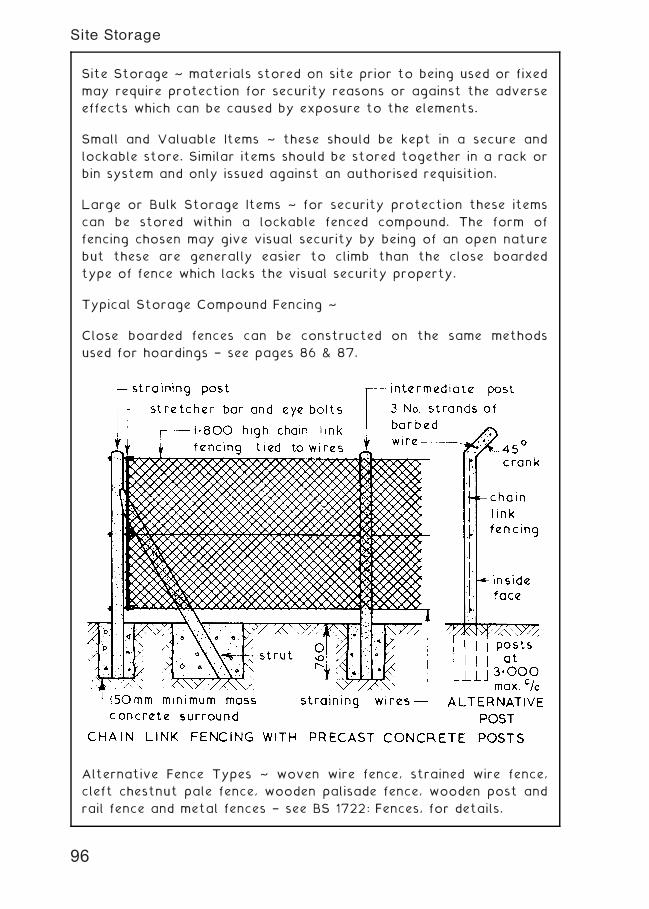
Site Storage ~ materials stored on site prior to being used or fixed
may require protection for security reasons or against the adverse
effects which can be caused by exposure to the elements.
Small and Valuable Items ~ these should be kept in a secure and
lockable store. Similar items should be stored together in a rack or
bin system and only issued against an authorised requisition.
Large or Bulk Storage Items ~ for security protection these items
can be stored within a lockable fenced compound. The form of
fencing chosen may give visual security by being of an open nature
but these are generally easier to climb than the close boarded
type of fence which lacks the visual security property.
Typical Storage Compound Fencing ~
Close boarded fences can be constructed on the same methods
used for hoardings † see pages 86 & 87.
Alternative Fence Types ~ woven wire fence, strained wire fence,
cleft chestnut pale fence, wooden palisade fence, wooden post and
rail fence and metal fences † see BS 1722: Fences, for details.
96
Site Storage
Storage of Materials ~ this can be defined as the provision of
adequate space, protection and control for building materials and
components held on site during the construction process. The
actual requirements for specific items should be familiar to
students who have completed studies in construction technology
at an introductory level but the need for storage and control of
materials held on site can be analysed further:-
1 . Physical Properties † size, shape, weight and mode of delivery
will assist in determining the safe handling and stacking
method(s) to be employed on site, which in turn will enable
handling and storage costs to be estimated.
2. Organisation † this is the planning process of ensuring that
all the materials required are delivered to site at the correct
time, in sufficient quantity, of the right quality, the means of
unloading is available and that adequate space for storage or
stacking has been allocated.
3. Protection † building materials and components can be
classified as durable or non-durable, the latter will usually
require some form of weather protection to prevent
deterioration whilst in store.
4. Security † many building materials have a high resale and/or
usage value to persons other than those for whom they were
ordered and unless site security is adequate material losses
can become unacceptable.
5. Costs † to achieve an economic balance of how much
expenditure can be allocated to site storage facilities the
following should be taken into account:-
a. Storage areas, fencing, racks, bins, etc.
b. Protection requirements.
c. Handling, transporting and stacking requirements.
d. Salaries and wages of staff involved in storage of materials
and components.
e. Heating and/or lighting if required.
f. Allowance for losses due to wastage, deterioration,
vandalism and theft.
g. Facilities to be provided for subcontractors.
6. Control † checking quality and quantity of materials at
delivery and during storage period, recording delivery and
issue of materials and monitoring stock holdings.
97
Materials Storage
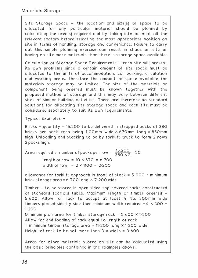
Site Storage Space ~ the location and size(s) of space to be
allocated for any particular material should be planned by
calculating the area(s) required and by taking into account all the
relevant factors before selecting the most appropriate position on
site in terms of handling, storage and convenience. Failure to carry
out this simple planning exercise can result in chaos on site or
having on site more materials than there is storage space available.
Calculation of Storage Space Requirements ~ each site will present
its own problems since a certain amount of site space must be
allocated to the units of accommodation, car parking, circulation
and working areas, therefore the amount of space available for
materials storage may be limited. The size of the materials or
component being ordered must be known together with the
proposed method of storage and this may vary between different
sites of similar building activities. There are therefore no standard
solutions for allocating site storage space and each site must be
considered separately to suit its own requirements.
Typical Examples ~
Bricks † quantity = 15,200 to be delivered in strapped packs of 380
bricks per pack each being 1100mm wide � 670mm long � 850mm
high. Unloading and stacking to be by forklift truck to form 2 rows
2 packs high.
Area required :- number of packs per row =15,200380 � 2
= 20
length of row = 10 � 670 = 6„700
width of row = 2 � 1100 = 2„200
allowance for forklift approach in front of stack = 5„000 \ minimum
brick storage area = 6„700 long � 7„200wide
Timber † to be stored in open sided top covered racks constructed
of standard scaffold tubes. Maximum length of timber ordered =
5„600. Allow for rack to accept at least 4 No. 300mm wide
timbers placed side by side then minimum width required = 4 � 300 =
1„200
Minimum plan area for timber storage rack = 5„600 � 1„200
Allow for end loading of rack equal to length of rack
\ minimum timber storage area = 11„200 long � 1„200 wide
Height of rack to be not more than 3 � width = 3„600
Areas for other materials stored on site can be calculated using
the basic principles contained in the examples above.
98
Materials Storage
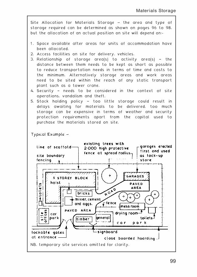
Site Allocation for Materials Storage ~ the area and type of
storage required can be determined as shown on pages 96 to 98,
but the allocation of an actual position on site will depend on:-
1 . Space available after areas for units of accommodation have
been allocated.
2. Access facilities on site for delivery, vehicles.
3. Relationship of storage area(s) to activity area(s) † the
distance between them needs to be kept as short as possible
to reduce transportation needs in terms of time and costs to
the minimum. Alternatively storage areas and work areas
need to be sited within the reach of any static transport
plant such as a tower crane.
4. Security † needs to be considered in the context of site
operations, vandalism and theft.
5. Stock holding policy † too little storage could result in
delays awaiting for materials to be delivered, too much
storage can be expensive in terms of weather and security
protection requirements apart from the capital used to
purchase the materials stored on site.
NB. temporary site services omitted for clarity.
99
Materials Storage
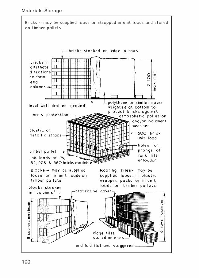
Bricks ~ may be supplied loose or strapped in unit loads and stored
on timber pallets
100
Materials Storage
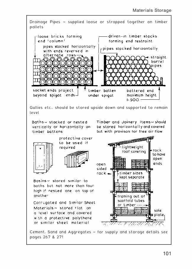
Drainage Pipes ~ supplied loose or strapped together on timber
pallets
Gullies etc., should be stored upside down and supported to remain
level
Cement, Sand and Aggregates ~ for supply and storage details see
pages 267 & 271
101
Materials Storage
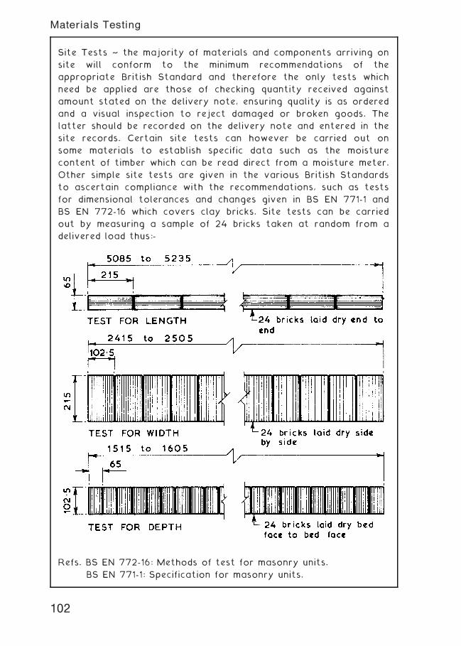
Site Tests ~ the majority of materials and components arriving on
site will conform to the minimum recommendations of the
appropriate British Standard and therefore the only tests which
need be applied are those of checking quantity received against
amount stated on the delivery note, ensuring quality is as ordered
and a visual inspection to reject damaged or broken goods. The
latter should be recorded on the delivery note and entered in the
site records. Certain site tests can however be carried out on
some materials to establish specific data such as the moisture
content of timber which can be read direct from a moisture meter.
Other simple site tests are given in the various British Standards
to ascertain compliance with the recommendations, such as tests
for dimensional tolerances and changes given in BS EN 771-1 and
BS EN 772-16 which covers clay bricks. Site tests can be carried
out by measuring a sample of 24 bricks taken at random from a
delivered load thus:-
Refs. BS EN 772-16: Methods of test for masonry units.
BS EN 771-1: Specification for masonry units.
102
Materials Testing
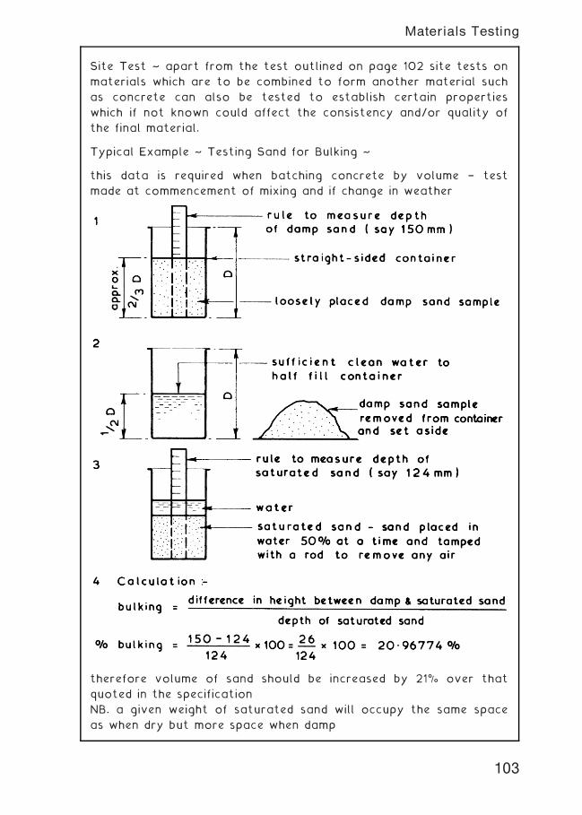
Site Test ~ apart from the test outlined on page 102 site tests on
materials which are to be combined to form another material such
as concrete can also be tested to establish certain properties
which if not known could affect the consistency and/or quality of
the final material.
Typical Example ~ Testing Sand for Bulking ~
this data is required when batching concrete by volume † test
made at commencement of mixing and if change in weather
therefore volume of sand should be increased by 21% over that
quoted in the specification
NB. a given weight of saturated sand will occupy the same space
as when dry but more space when damp
103
Materials Testing
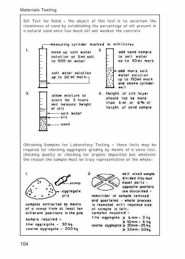
Silt Test for Sand ~ the object of this test is to ascertain the
cleanliness of sand by establishing the percentage of silt present in
a natural sand since too much silt will weaken the concrete
Obtaining Samples for Laboratory Testing ~ these tests may be
required for checking aggregate grading by means of a sieve test,
checking quality or checking for organic impurities but whatever
the reason the sample must be truly representative of the whole:-
104
Materials Testing
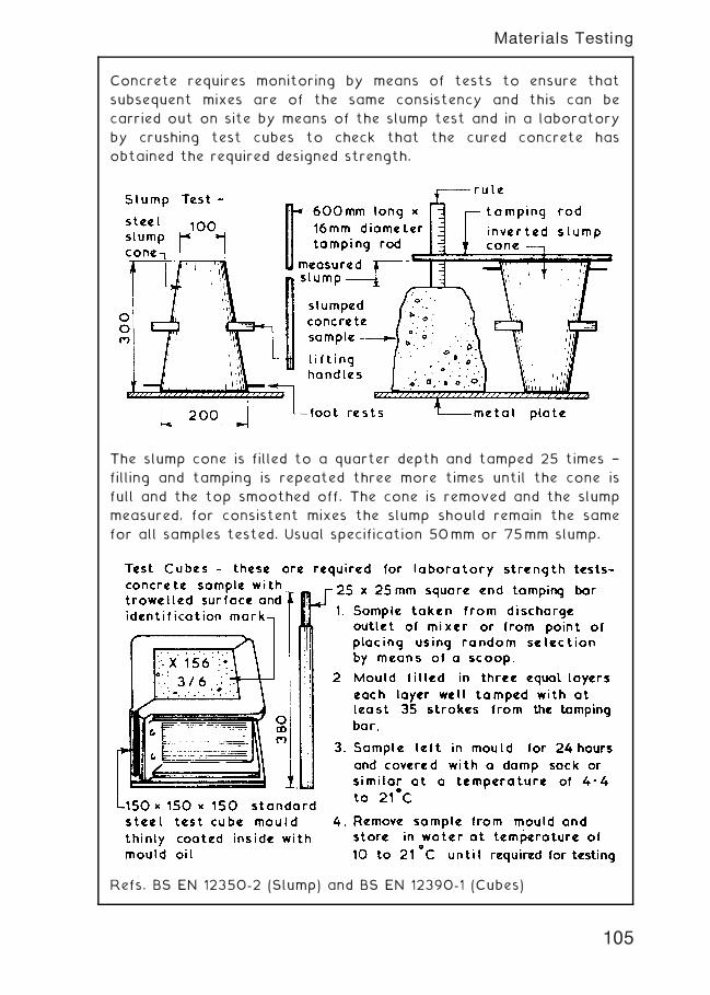
Concrete requires monitoring by means of tests to ensure that
subsequent mixes are of the same consistency and this can be
carried out on site by means of the slump test and in a laboratory
by crushing test cubes to check that the cured concrete has
obtained the required designed strength.
The slump cone is filled to a quarter depth and tamped 25 times †
filling and tamping is repeated three more times until the cone is
full and the top smoothed off. The cone is removed and the slump
measured, for consistent mixes the slump should remain the same
for all samples tested. Usual specification 50mm or 75mm slump.
Refs. BS EN 12350-2 (Slump) and BS EN 12390-1 (Cubes)
105
Materials Testing
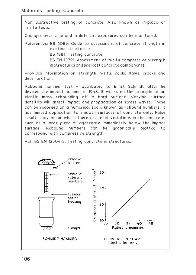
Non destructive testing of concrete. Also known as in-place or
in-situ tests.
Changes over time and in different exposures can be monitored.
References: BS 6089: Guide to assessment of concrete strength in
existing structures;
BS 1881: Testing concrete.
BS EN 13791: Assessment of in-situ compressive strength
in structuresandpre-cast concrete components.
Provides information on: strength in-situ, voids, flaws, cracks and
deterioration.
Rebound hammer test † attributed to Ernst Schmidt after he
devised the impact hammer in 1948. It works on the principle of an
elastic mass rebounding off a hard surface. Varying surface
densities will affect impact and propagation of stress waves. These
can be recorded on a numerical scale known as rebound numbers. It
has limited application to smooth surfaces of concrete only. False
results may occur where there are local variations in the concrete,
such as a large piece of aggregate immediately below the impact
surface. Rebound numbers can be graphically plotted to
correspond with compressive strength.
Ref: BS EN 12504-2: Testing concrete in structures.
106
Materials Testing---Concrete
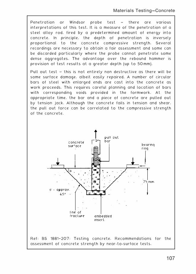
Penetration or Windsor probe test ~ there are various
interpretations of this test. It is a measure of the penetration of a
steel alloy rod, fired by a predetermined amount of energy into
concrete. In principle, the depth of penetration is inversely
proportional to the concrete compressive strength. Several
recordings are necessary to obtain a fair assessment and some can
be discarded particularly where the probe cannot penetrate some
dense aggregates. The advantage over the rebound hammer is
provision of test results at a greater depth (up to 50mm).
Pull out test ~ this is not entirely non destructive as there will be
some surface damage, albeit easily repaired. A number of circular
bars of steel with enlarged ends are cast into the concrete as
work proceeds. This requires careful planning and location of bars
with corresponding voids provided in the formwork. At the
appropriate time, the bar and a piece of concrete are pulled out
by tension jack. Although the concrete fails in tension and shear,
the pull out force can be correlated to the compressive strength
of the concrete.
Ref: BS 1881†207: Testing concrete. Recommendations for the
assessment of concrete strength by near-to-surface tests.
107
Materials Testing---Concrete
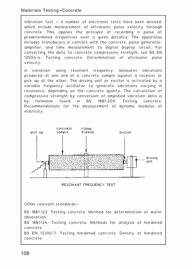
Vibration test ~ a number of electronic tests have been devised,
which include measurement of ultrasonic pulse velocity through
concrete. This applies the principle of recording a pulse at
predetermined frequencies over a given distance. The apparatus
includes transducers in contact with the concrete, pulse generator,
amplifier, and time measurement to digital display circuit. For
converting the data to concrete compressive strength, see BS EN
12504-4: Testing concrete. Determination of ultrasonic pulse
velocity.
A variation, using resonant frequency, measures vibrations
produced at one end of a concrete sample against a receiver or
pick up at the other. The driving unit or exciter is activated by a
variable frequency oscillator to generate vibrations varying in
resonance, depending on the concrete quality. The calculation of
compressive strength by conversion of amplified vibration data is
by formulae found in BS 1881-209: Testing concrete.
Recommendations for the measurement of dynamic modulus of
elasticity.
Other relevant standards:†
BS 1881-122: Testing concrete. Method for determination of water
absorption.
BS 1881-124: Testing concrete. Methods for analysis of hardened
concrete.
BS EN 12390-7: Testing hardened concrete. Density of hardened
concrete.
108
Materials Testing---Concrete
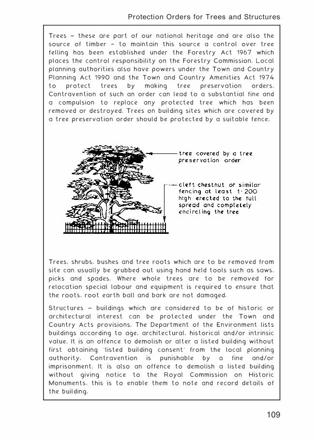
Trees ~ these are part of our national heritage and are also the
source of timber † to maintain this source a control over tree
felling has been established under the Forestry Act 1967 which
places the control responsibility on the Forestry Commission. Local
planning authorities also have powers under the Town and Country
Planning Act 1990 and the Town and Country Amenities Act 1974
to protect trees by making tree preservation orders.
Contravention of such an order can lead to a substantial fine and
a compulsion to replace any protected tree which has been
removed or destroyed. Trees on building sites which are covered by
a tree preservation order should be protected by a suitable fence.
Trees, shrubs, bushes and tree roots which are to be removed from
site can usually be grubbed out using hand held tools such as saws,
picks and spades. Where whole trees are to be removed for
relocation special labour and equipment is required to ensure that
the roots, root earth ball and bark are not damaged.
Structures ~ buildings which are considered to be of historic or
architectural interest can be protected under the Town and
Country Acts provisions. The Department of the Environment lists
buildings according to age, architectural, historical and/or intrinsic
value. It is an offence to demolish or alter a listed building without
first obtaining `listed building consent' from the local planning
authority. Contravention is punishable by a fine and/or
imprisonment. It is also an offence to demolish a listed building
without giving notice to the Royal Commission on Historic
Monuments, this is to enable them to note and record details of
the building.
109
Protection Orders for Trees and Structures
Services which may be encountered on construction sites and the
authority responsible are:-
Water † Local Water Company
Electricity † transmission ~ RWE npower, BNFL and E-on.
distribution ~ Area Electricity Companies in England
and Wales. Scottish Power and Scottish
Hydro-Electric, EDF Energy.
Gas † Local gas or energy service providers, e.g. British Gas.
Telephones † National Telecommunications Companys, eg. BT, C&W,
etc.
Drainage † Local Authority unless a private drain or sewer when
owner(s) is responsible.
All the above authorities must be notified of any proposed new
services and alterations or terminations to existing services before
any work is carried out.
Locating Existing Services on Site ~
Method 1 † By reference to maps and plans prepared and issued by
the respective responsible authority.
Method 2 † Using visual indicators ~
Method 3 † Detection specialist contractor employed to trace all
forms of underground services using electronic
subsurface survey equipment.
Once located, position and type of service can be plotted on
a map or plan, marked with special paint on hard surfaces
and marked with wood pegs with indentification data on earth
surfaces.
110
Locating Public Utility Services
Setting Out the Building Outline ~ this task is usually undertaken
once the site has been cleared of any debris or obstructions and any
reduced level excavation work is finished. It is usually the
responsibility of the contractor to set out the building(s) using the
information provided by the designer or architect. Accurate setting
out is of paramount importance and should therefore only be carried
out by competent persons and all their work thoroughly checked,
preferably by different personnel and by a different method.
The first task in setting out the building is to establish a base line
to which all the setting out can be related. The base line very
often coincides with the building line which is a line, whose position
on site is given by the local authority in front of which no
development is permitted.
111
Setting Out
Setting Out Trenches ~ the objective of this task is twofold.
Firstly it must establish the excavation size, shape and direction
and secondly it must establish the width and position of the walls.
The outline of building will have been set out and using this outline
profile boards can be set up to control the position, width and
possibly the depth of the proposed trenches. Profile boards should
be set up at least 2„000 clear of trench positions so they do not
obstruct the excavation work. The level of the profile crossboard
should be related to the site datum and fixed at a convenient
height above ground level if a traveller is to be used to control
the depth of the trench. Alternatively the trench depth can be
controlled using a level and staff related to site datum. The trench
width can be marked on the profile with either nails or sawcuts and
with a painted band if required for identification.
NB. Corners of walls transferred from intersecting cord lines to
mortar spots on concrete foundations using a spirit level
112
Setting Out
Setting Out a Framed Building ~ framed buildings are usually
related to a grid, the intersections of the grid lines being the
centre point of an isolated or pad foundation. The grid is usually
set out from a base line which does not always form part of the
grid. Setting out dimensions for locating the grid can either be
given on a drawing or they will have to be accurately scaled off a
general layout plan. The grid is established using a theodolite and
marking the grid line intersections with stout pegs. Once the grid
has been set out offset pegs or profiles can be fixed clear of any
subsequent excavation work. Control of excavation depth can be
by means of a traveller sighted between sight rails or by level and
staff related to site datum.
113
Setting Out
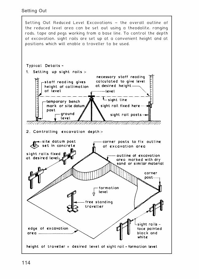
Setting Out Reduced Level Excavations ~ the overall outline of
the reduced level area can be set out using a theodolite, ranging
rods, tape and pegs working from a base line. To control the depth
of excavation, sight rails are set up at a convenient height and at
positions which will enable a traveller to be used.
114
Setting Out
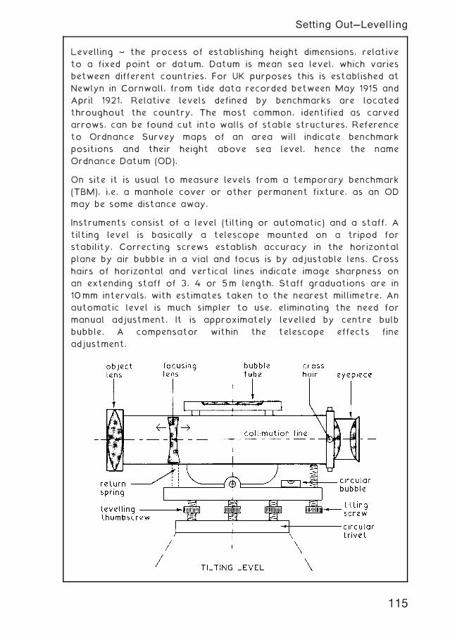
Levelling ~ the process of establishing height dimensions, relative
to a fixed point or datum. Datum is mean sea level, which varies
between different countries. For UK purposes this is established at
Newlyn in Cornwall, from tide data recorded between May 1915 and
April 1921. Relative levels defined by benchmarks are located
throughout the country. The most common, identified as carved
arrows, can be found cut into walls of stable structures. Reference
to Ordnance Survey maps of an area will indicate benchmark
positions and their height above sea level, hence the name
Ordnance Datum (OD).
On site it is usual to measure levels from a temporary benchmark
(TBM), i.e. a manhole cover or other permanent fixture, as an OD
may be some distance away.
Instruments consist of a level (tilting or automatic) and a staff. A
tilting level is basically a telescope mounted on a tripod for
stability. Correcting screws establish accuracy in the horizontal
plane by air bubble in a vial and focus is by adjustable lens. Cross
hairs of horizontal and vertical lines indicate image sharpness on
an extending staff of 3, 4 or 5m length. Staff graduations are in
10mm intervals, with estimates taken to the nearest millimetre. An
automatic level is much simpler to use, eliminating the need for
manual adjustment. It is approximately levelled by centre bulb
bubble. A compensator within the telescope effects fine
adjustment.
115
Setting Out---Levelling

116
Setting Out---Levelling
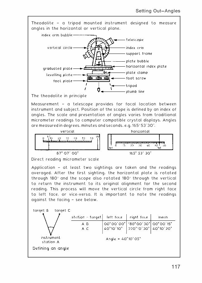
Theodolite † a tripod mounted instrument designed to measure
angles in the horizontal or vertical plane.
The theodolite in principle
Measurement † a telescope provides for focal location between
instrument and subject. Position of the scope is defined by an index of
angles. The scale and presentation of angles varies from traditional
micrometer readings to computer compatible crystal displays. Angles
aremeasured in degrees,minutes and seconds, e.g. 165� 530 3000.
Direct reading micrometer scale
Application † at least two sightings are taken and the readings
averaged. After the first sighting, the horizontal plate is rotated
through 180� and the scope also rotated 180� through the vertical
to return the instrument to its original alignment for the second
reading. This process will move the vertical circle from right face
to left face, or vice-versa. It is important to note the readings
against the facing † see below.
117
Setting Out---Angles
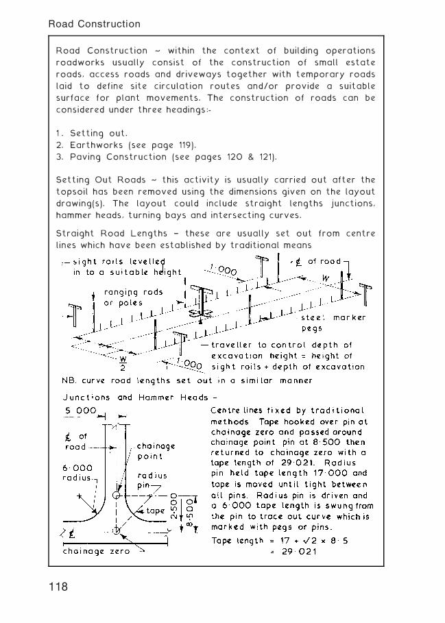
Road Construction ~ within the context of building operations
roadworks usually consist of the construction of small estate
roads, access roads and driveways together with temporary roads
laid to define site circulation routes and/or provide a suitable
surface for plant movements. The construction of roads can be
considered under three headings:-
1 . Setting out.
2. Earthworks (see page 119).
3. Paving Construction (see pages 120 & 121).
Setting Out Roads ~ this activity is usually carried out after the
topsoil has been removed using the dimensions given on the layout
drawing(s). The layout could include straight lengths junctions,
hammer heads, turning bays and intersecting curves.
Straight Road Lengths † these are usually set out from centre
lines which have been established by traditional means
118
Road Construction
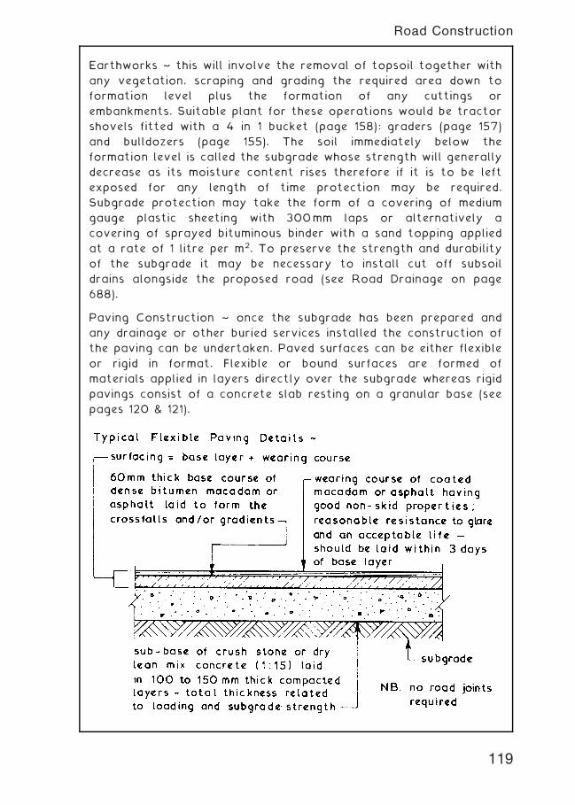
Earthworks ~ this will involve the removal of topsoil together with
any vegetation, scraping and grading the required area down to
formation level plus the formation of any cuttings or
embankments. Suitable plant for these operations would be tractor
shovels fitted with a 4 in 1 bucket (page 158): graders (page 157)
and bulldozers (page 155). The soil immediately below the
formation level is called the subgrade whose strength will generally
decrease as its moisture content rises therefore if it is to be left
exposed for any length of time protection may be required.
Subgrade protection may take the form of a covering of medium
gauge plastic sheeting with 300mm laps or alternatively a
covering of sprayed bituminous binder with a sand topping applied
at a rate of 1 litre per m2. To preserve the strength and durability
of the subgrade it may be necessary to install cut off subsoil
drains alongside the proposed road (see Road Drainage on page
688).
Paving Construction ~ once the subgrade has been prepared and
any drainage or other buried services installed the construction of
the paving can be undertaken. Paved surfaces can be either flexible
or rigid in format. Flexible or bound surfaces are formed of
materials applied in layers directly over the subgrade whereas rigid
pavings consist of a concrete slab resting on a granular base (see
pages 120 & 121).
119
Road Construction
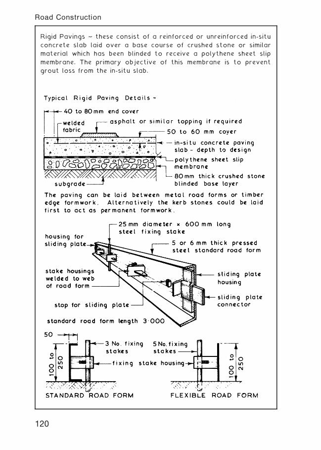
Rigid Pavings ~ these consist of a reinforced or unreinforced in-situ
concrete slab laid over a base course of crushed stone or similar
material which has been blinded to receive a polythene sheet slip
membrane. The primary objective of this membrane is to prevent
grout loss from the in-situ slab.
120
Road Construction
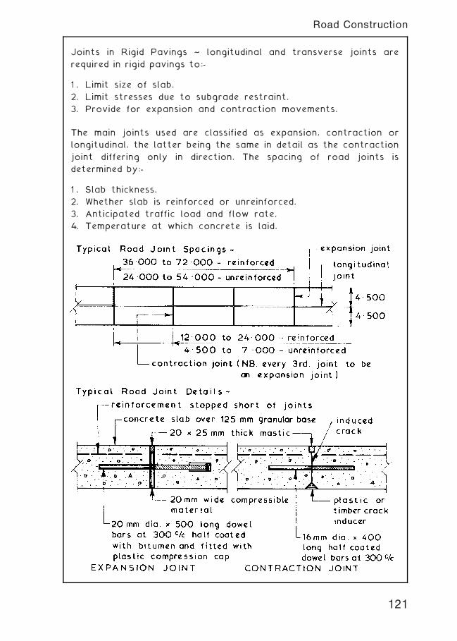
Joints in Rigid Pavings ~ longitudinal and transverse joints are
required in rigid pavings to:-
1 . Limit size of slab.
2. Limit stresses due to subgrade restraint.
3. Provide for expansion and contraction movements.
The main joints used are classified as expansion, contraction or
longitudinal, the latter being the same in detail as the contraction
joint differing only in direction. The spacing of road joints is
determined by:-
1 . Slab thickness.
2. Whether slab is reinforced or unreinforced.
3. Anticipated traffic load and flow rate.
4. Temperature at which concrete is laid.
121
Road Construction
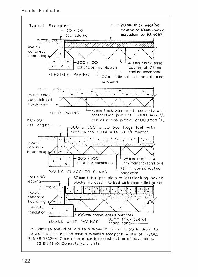
122
Roads---Footpaths
123
Roads---Kerbs, Pavings and Edgings
Concrete paving flags † BS dimensions:
Note: All dimensions in millimetres.
Tactile flags † manufactured with a blistered (shown) or ribbed
surface. Used in walkways to provide warning of hazards or to
enable recognition of locations for people whose visibility is
impaired. See also, Department of Transport Disability Circular DU
1/86[1], for uses and applications.
Ref. BS 7263†1: Pre-cast concrete flags, kerbs, channels, edgings
and quadrants.
BS EN 1339: Concrete paving flags.
Type Size (nominal) Size (work) Thickness (T)
A † plain 600 � 450 598 � 448 50 or 63
B † plain 600 � 600 598 � 598 50 or 63
C † plain 600 � 750 598 � 748 50 or 63
D † plain 600 � 900 598 � 898 50 or 63
E † plain 450 � 450 448� 448 50 or 70
TA/E † tactile 450 � 450 448� 448 50 or 70
TA/F † tactile 400 � 400 398 � 398 50 or 65
TA/G † tactile 300 � 300 298 � 298 50 or 60
124
Roads---Kerbs, Pavings and Edgings
Landscaping ~ in the context of building works this would involve
reinstatement of the site as a preparation to the landscaping in
the form of lawns, paths, pavings, flower and shrub beds and tree
planting. The actual planning, lawn laying and planting activities
are normally undertaken by a landscape subcontractor. The main
contractor's work would involve clearing away all waste and
unwanted materials, breaking up and levelling surface areas,
removing all unwanted vegetation, preparing the subsoil for and
spreading topsoil to a depth of at least 150mm.
Services ~ the actual position and laying of services is the
responsibility of the various service boards and undertakings. The
best method is to use the common trench approach, avoid as far
as practicable laying services under the highway.
125
Roads---Kerbs, Pavings and Edgings
Scaffolds ~ these are temporary working platforms erected around
the perimeter of a building or structure to provide a safe working
place at a convenient height. They are usually required when the
working height or level is 1„500 or more above the ground level.
All scaffolds must comply with the minimum requirements and
objectives of the Work at Height Regulations 2005.
Component Parts of a Tubular Scaffold ~
standard
all tubes tocomply with BS EN 39or BS 1139-1.2
transom orputlog
ledger
ledger
double coupler
putlog coupler
standard
ledger
base plate withlocating spigotplan size 150 ×150
transverse horizontalmember called atransom fixed to ledgers
HORIZONTAL COMPONENTS
VERTICAL COMPONENT SLOPING COMPONENTS
all bracing fixed with swivel couplers
crossbrace
timber sole plateunder base plateson soft or unevenground
transverse horizontalmember called aputlog — fixed toledger with a putlog coupler
longitudinal horizontalmember called aledger — fixed to standards with doublecouplers
blade end standard
transom orputlog
vertical memberusually called astandard spacedat 1.800 to2.400 centresdepending onload to be carried
transoms or
putlogs
facadebrace
Refs. BS EN 39: Loose steel tubes for tube and coupler scaffolds.
BS 1139-1.2: Metal scaffolding. Tubes. Specification for
aluminium tube.
126
Tubular Scaffolding
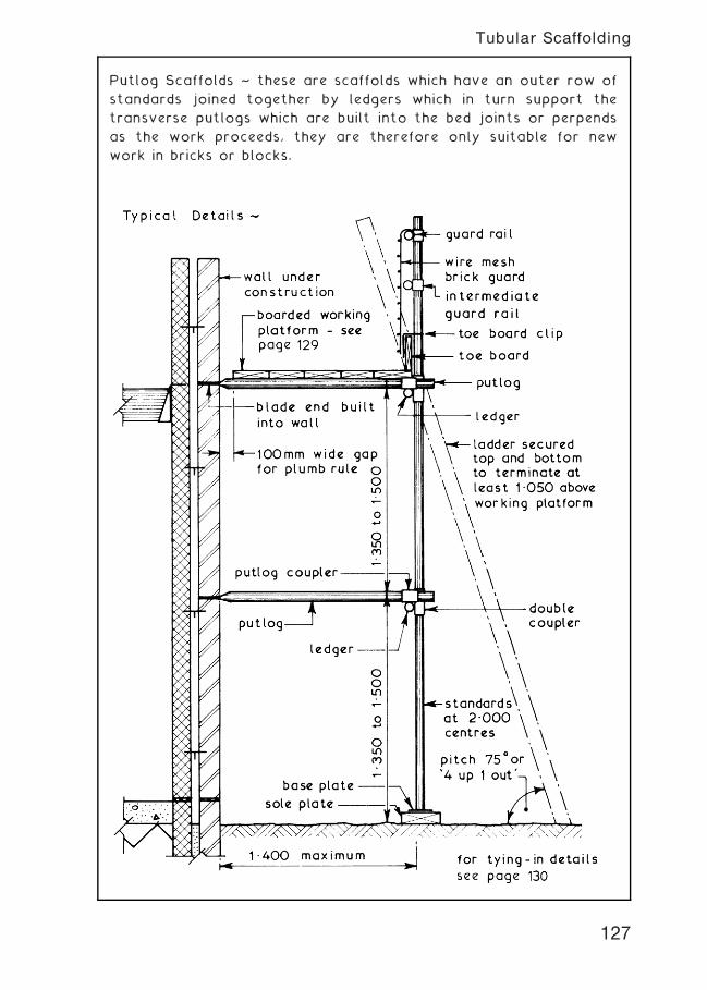
Putlog Scaffolds ~ these are scaffolds which have an outer row of
standards joined together by ledgers which in turn support the
transverse putlogs which are built into the bed joints or perpends
as the work proceeds, they are therefore only suitable for new
work in bricks or blocks.
127
Tubular Scaffolding
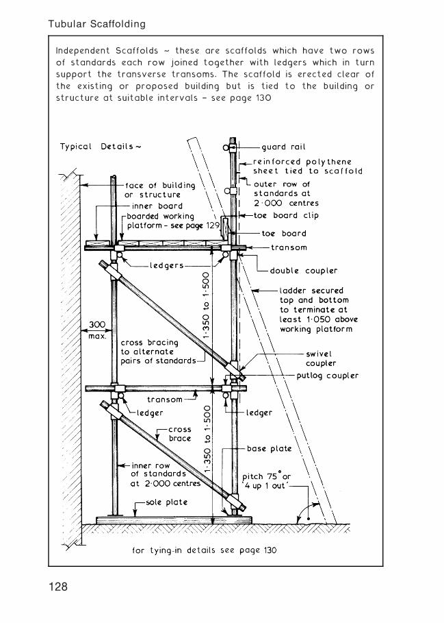
Independent Scaffolds ~ these are scaffolds which have two rows
of standards each row joined together with ledgers which in turn
support the transverse transoms. The scaffold is erected clear of
the existing or proposed building but is tied to the building or
structure at suitable intervals † see page 130
128
Tubular Scaffolding
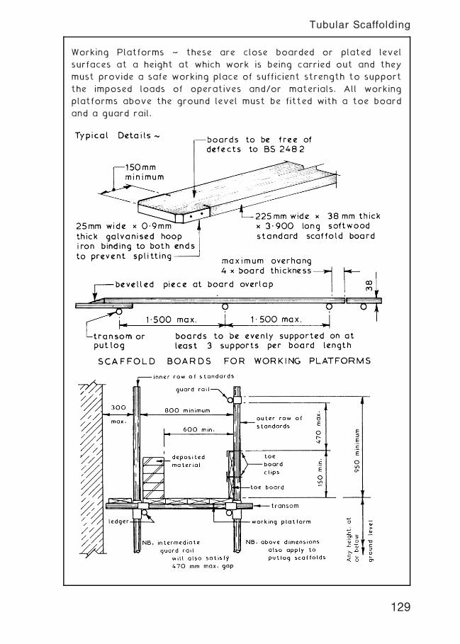
Working Platforms ~ these are close boarded or plated level
surfaces at a height at which work is being carried out and they
must provide a safe working place of sufficient strength to support
the imposed loads of operatives and/or materials. All working
platforms above the ground level must be fitted with a toe board
and a guard rail.
129
Tubular Scaffolding
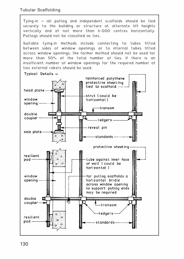
Tying-in ~ all putlog and independent scaffolds should be tied
securely to the building or structure at alternate lift heights
vertically and at not more than 6„000 centres horizontally.
Putlogs should not be classified as ties.
Suitable tying-in methods include connecting to tubes fitted
between sides of window openings or to internal tubes fitted
across window openings, the former method should not be used for
more than 50% of the total number of ties. If there is an
insufficient number of window openings for the required number of
ties external rakers should be used.
130
Tubular Scaffolding
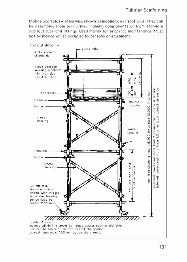
Mobile Scaffolds ~ otherwise known asmobile tower scaffolds. They can
be assembled from pre-formed framing components or from standard
scaffold tube and fittings. Used mainly for property maintenance. Must
not be moved whilst occupied by persons or equipment.
131
Tubular Scaffolding
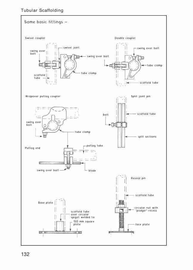
Some basic fittings ~
Reveal pin
Base plate
scaffold tube
scaffold tubeover circularspigot welded to
150 mm squareplate
circular nut with"podger" recess
face plate
Wrapover putlog coupler Split joint pin
bolt
swing overbolt
swing over bolt
Putlog endputlog tube
blade
scaffold tube
split sections
tube clamp
Swivel coupler Double coupler
swivel joint
swing overbolt
scaffoldtube
scaffold tube
tube clamp
tube clamp
swing over bolt
swing over bolt
132
Tubular Scaffolding
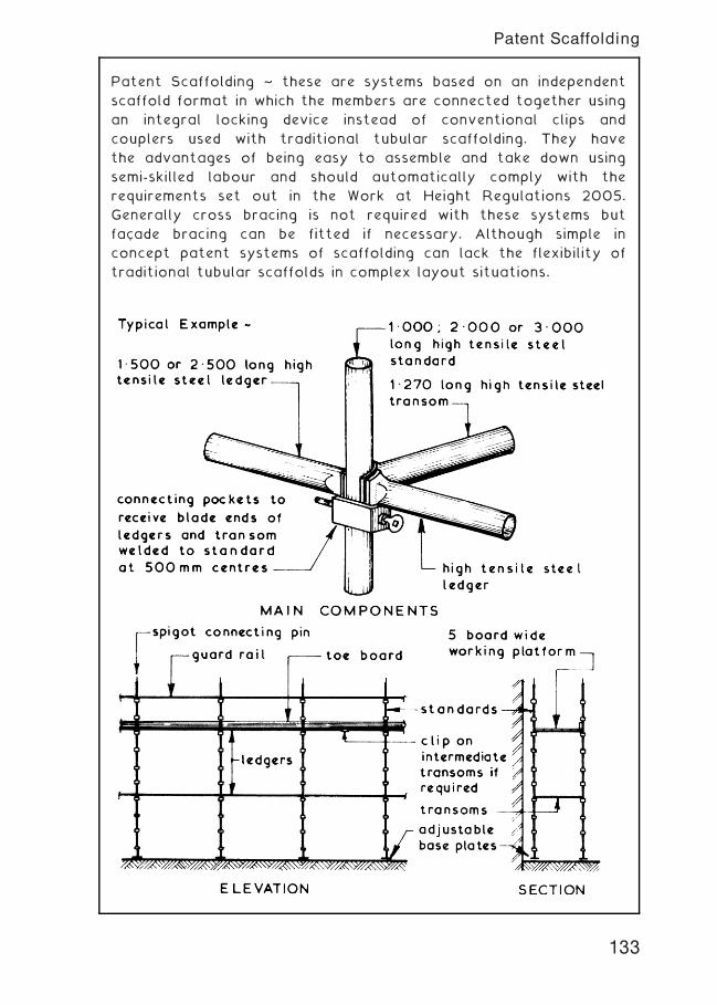
Patent Scaffolding ~ these are systems based on an independent
scaffold format in which the members are connected together using
an integral locking device instead of conventional clips and
couplers used with traditional tubular scaffolding. They have
the advantages of being easy to assemble and take down using
semi-skilled labour and should automatically comply with the
requirements set out in the Work at Height Regulations 2005.
Generally cross bracing is not required with these systems but
facade bracing can be fitted if necessary. Although simple in
concept patent systems of scaffolding can lack the flexibility of
traditional tubular scaffolds in complex layout situations.
133
Patent Scaffolding
Scaffolding Systems ~ these are temporary stagings to provide
safe access to and egress from a working platform. The
traditional putlog and independent scaffolds have been covered on
pages 126 to 130 inclusive. The minimum legal requirements
contained in the Construction (Health Safety and Welfare)
Regulations 1996 applicable to traditional scaffolds apply equally
to special scaffolds. Special scaffolds are designed to fulfil a
specific function or to provide access to areas where it is not
possible and or economic to use traditional formats. They can be
constructed from standard tubes or patent systems, the latter
complying with most regulation requirements are easy and quick
to assemble but lack the complete flexibility of the traditional
tubular scaffolds.
Birdcage Scaffolds ~ these are a form of independent scaffold
normally used for internal work in large buildings such as public
halls and churches to provide access to ceilings and soffits for
light maintenance work like painting and cleaning. They consist of
parallel rows of standards connected by leaders in both directions,
the whole arrangement being firmly braced in all directions. The
whole birdcage scaffold assembly is designed to support a single
working platform which should be double planked or underlined with
polythene or similar sheeting as a means of restricting the amount
of dust reaching the floor level.
Slung Scaffolds ~ these are a form of scaffold which is suspended
from the main structure by means of wire ropes or steel chains and
is not provided with a means of being raised or lowered. Each
working platform of a slung scaffold consists of a supporting
framework of ledgers and transoms which should not create a plan
size in excess of 2„500� 2„500 and be held in position by not less
than six evenly spaced wire ropes or steel chains securely anchored
at both ends. The working platform should be double planked or
underlined with polythene or similar sheeting to restrict the
amount of dust reaching the floor level. Slung scaffolds are an
alternative to birdcage scaffolds and although more difficult to
erect have the advantage of leaving a clear space beneath the
working platform which makes them suitable for cinemas, theatres
and high ceiling banking halls.
134
Scaffolding Systems
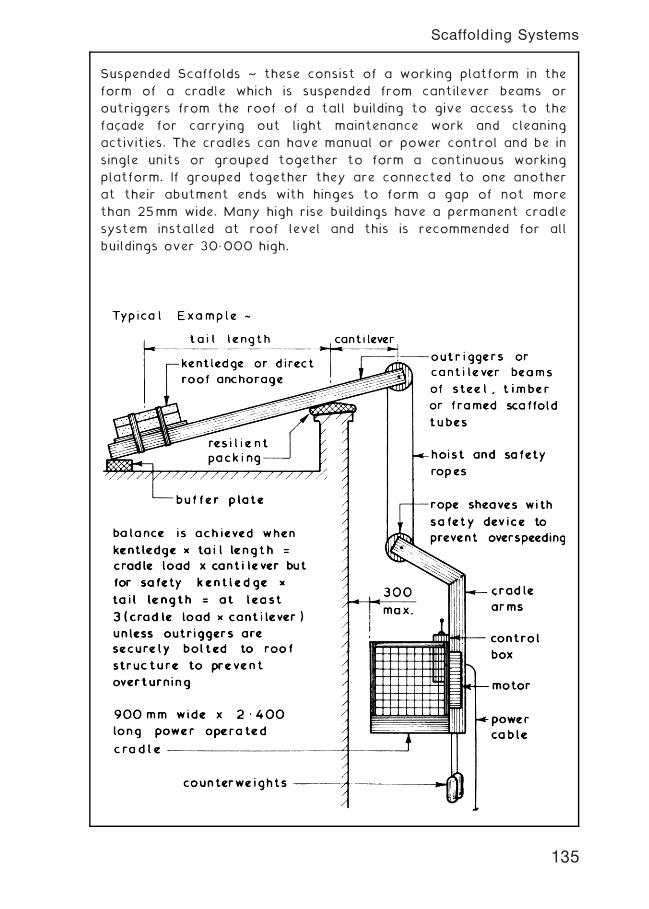
Suspended Scaffolds ~ these consist of a working platform in the
form of a cradle which is suspended from cantilever beams or
outriggers from the roof of a tall building to give access to the
facade for carrying out light maintenance work and cleaning
activities. The cradles can have manual or power control and be in
single units or grouped together to form a continuous working
platform. If grouped together they are connected to one another
at their abutment ends with hinges to form a gap of not more
than 25mm wide. Many high rise buildings have a permanent cradle
system installed at roof level and this is recommended for all
buildings over 30„000 high.
135
Scaffolding Systems
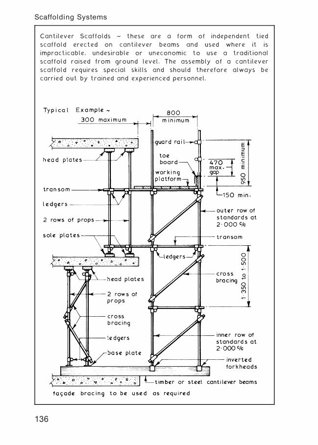
Cantilever Scaffolds ~ these are a form of independent tied
scaffold erected on cantilever beams and used where it is
impracticable, undesirable or uneconomic to use a traditional
scaffold raised from ground level. The assembly of a cantilever
scaffold requires special skills and should therefore always be
carried out by trained and experienced personnel.
136
Scaffolding Systems
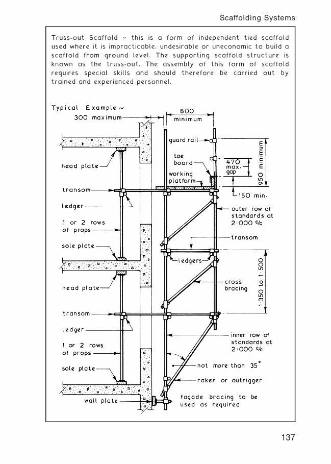
Truss-out Scaffold ~ this is a form of independent tied scaffold
used where it is impracticable, undesirable or uneconomic to build a
scaffold from ground level. The supporting scaffold structure is
known as the truss-out. The assembly of this form of scaffold
requires special skills and should therefore be carried out by
trained and experienced personnel.
137
Scaffolding Systems
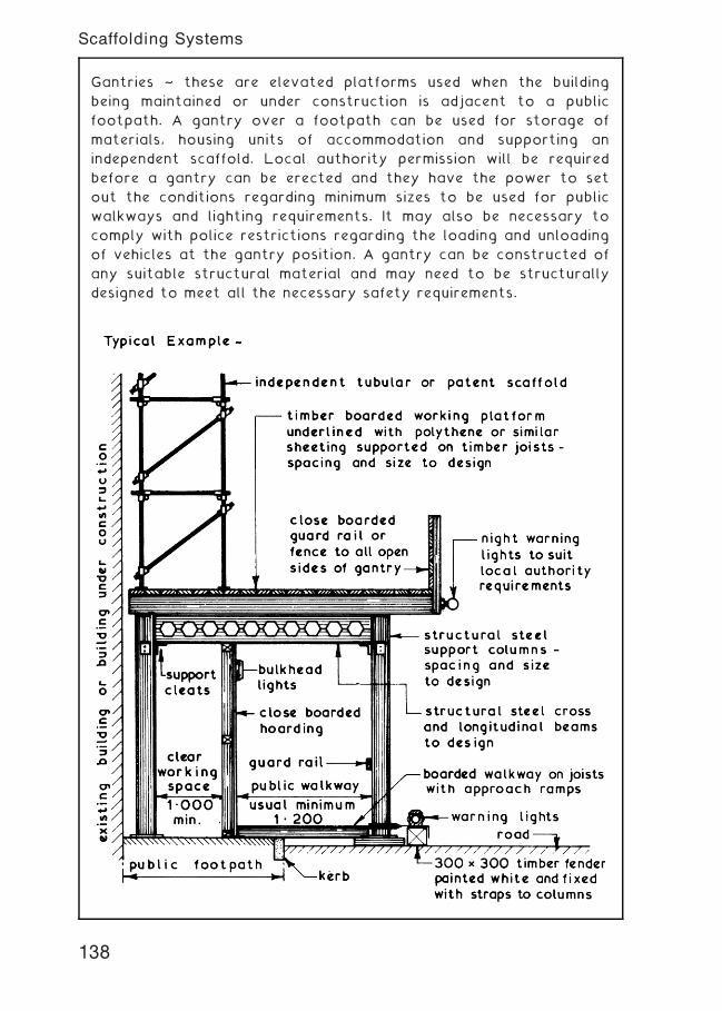
Gantries ~ these are elevated platforms used when the building
being maintained or under construction is adjacent to a public
footpath. A gantry over a footpath can be used for storage of
materials, housing units of accommodation and supporting an
independent scaffold. Local authority permission will be required
before a gantry can be erected and they have the power to set
out the conditions regarding minimum sizes to be used for public
walkways and lighting requirements. It may also be necessary to
comply with police restrictions regarding the loading and unloading
of vehicles at the gantry position. A gantry can be constructed of
any suitable structural material and may need to be structurally
designed to meet all the necessary safety requirements.
138
Scaffolding Systems
Shoring ~ this is a form of temporary support which can be given
to existing buildings with the primary function of providing the
necessary precautions to avoid damage to any person from
collapse of structure as required by the Construction (Health,
Safety and Welfare) Regulations 1996.
Shoring Systems ~ there are three basic systems of shoring which
can be used separately or in combination with one another to
provide the support(s) and these are namely:-
1 . Dead Shoring † used primarily to carry vertical loadings.
2. Raking Shoring † used to support a combination of vertical and
horizontal loadings.
3. Flying Shoring † an alternative to raking shoring to give a clear
working space at ground level.
139
Shoring
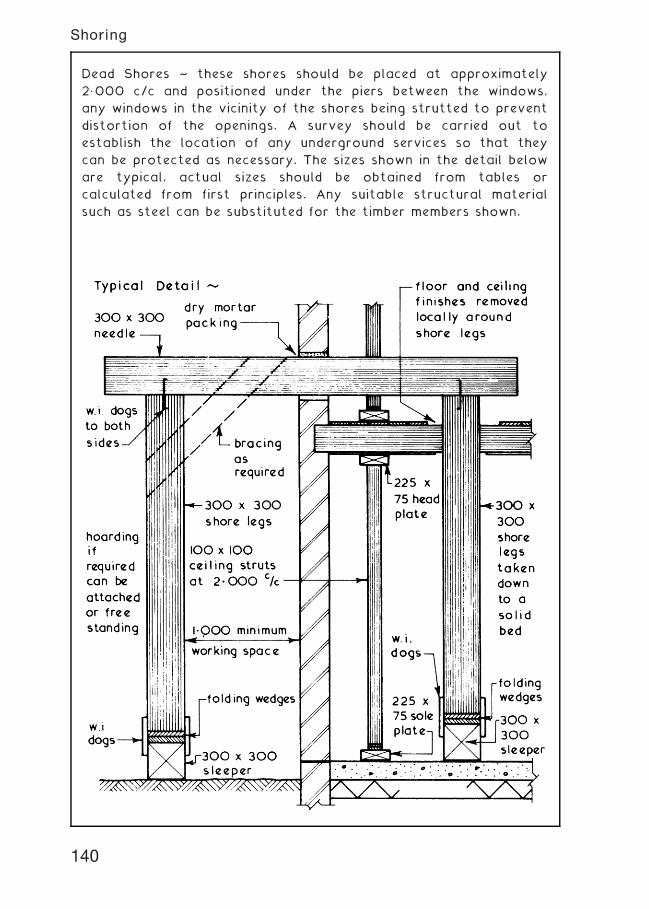
Dead Shores ~ these shores should be placed at approximately
2„000 c/c and positioned under the piers between the windows,
any windows in the vicinity of the shores being strutted to prevent
distortion of the openings. A survey should be carried out to
establish the location of any underground services so that they
can be protected as necessary. The sizes shown in the detail below
are typical, actual sizes should be obtained from tables or
calculated from first principles. Any suitable structural material
such as steel can be substituted for the timber members shown.
140
Shoring
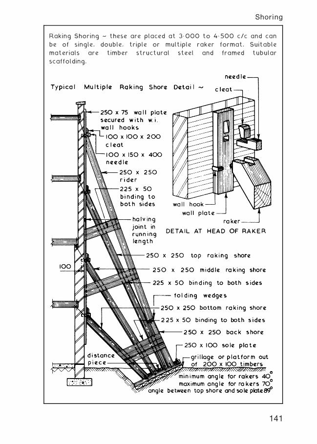
Raking Shoring ~ these are placed at 3„000 to 4„500 c/c and can
be of single, double, triple or multiple raker format. Suitable
materials are timber structural steel and framed tubular
scaffolding.
141
Shoring
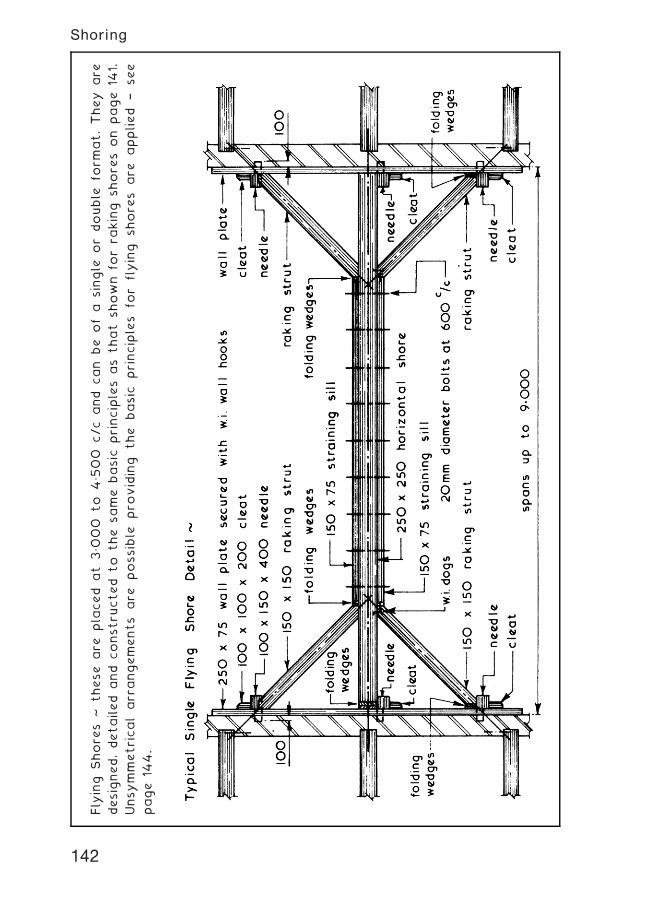
Fly
ing
Shore
s~
these
are
pla
ced
at
3„0
00
to
4„500
c/c
and
can
be
ofa
single
or
double
form
at.They
are
designed,detailed
and
constru
cted
to
the
same
basic
principles
as
that
shown
forra
king
shore
son
page
141.
Unsymmetricalarr
angements
are
possible
pro
viding
the
basic
principles
for
flying
shore
sare
applied
†see
page
144.
142
Shoring
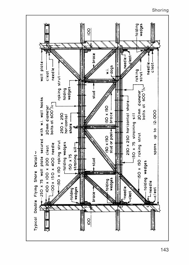
143
Shoring
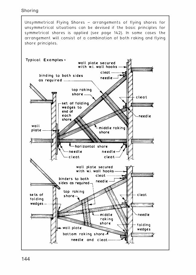
Unsymmetrical Flying Shores ~ arrangements of flying shores for
unsymmetrical situations can be devised if the basic principles for
symmetrical shores is applied (see page 142). In some cases the
arrangement will consist of a combination of both raking and flying
shore principles.
144
Shoring
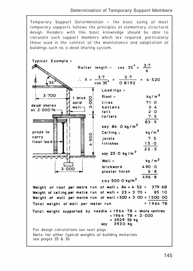
Temporary Support Determination ~ the basic sizing of most
temporary supports follows the principles of elementary structural
design. Readers with this basic knowledge should be able to
calculate such support members which are required, particularly
those used in the context of the maintenance and adaptation of
buildings such as a dead shoring system.
145
Determination of Temporary Support Members
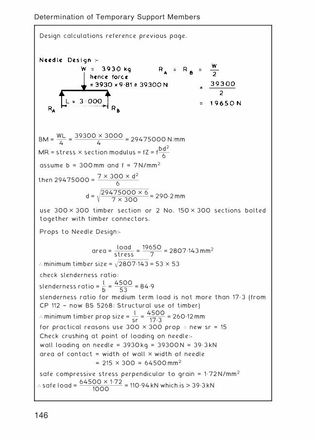
Design calculations reference previous page.
BM =WL4
=39300 � 3000
4= 29475000 N=mm
MR = stress � section modulus = fZ = fbd2
6
assume b = 300mm and f = 7N/mm2
then 29475000 =7 � 300 � d2
6
d =
ffiffiffiffiffiffiffiffiffiffiffiffiffiffiffiffiffiffiffiffiffiffiffiffiffiffiffiffiffiffiffiffiffiffiffiffiffiffiffiffiffiffiffiffiffiffiffiffiffiffiffi
29475000 � 67 � 300
s
= 290„2mm
use 300� 300 timber section or 2 No. 150� 300 sections bolted
together with timber connectors.
Props to Needle Design:-
area =loadstress
=19650
7= 2807„143mm2
\ minimum timber size =ffiffiffiffiffiffiffiffiffiffiffiffiffiffiffiffiffiffiffiffiffiffiffiffiffiffiffiffiffiffiffiffi
2807„143q
= 53 � 53
check slenderness ratio:
slenderness ratio =lb
=450053
= 84„9
slenderness ratio for medium term load is not more than 17„3 (from
CP 112 † now BS 5268: Structural use of timber)
\ minimum timber prop size =lsr
=450017„3
= 260„12mm
for practical reasons use 300 � 300 prop \ new sr = 15
Check crushing at point of loading on needle:-
wall loading on needle = 3930kg = 39300N = 39„3kN
area of contact = width of wall � width of needle
= 215 � 300 = 64500mm2
safe compressive stress perpendicular to grain = 1„72N/mm2
\ safe load =64500 � 1„72
1000= 110„94kN which is > 39„3kN
146
Determination of Temporary Support Members
Town and Country Planning Act ~ demolition is generally not regarded
as development, but planning permission will be required if the site is to
have a change of use. Attitudes to demolition can vary between local
planning authorities and consultation should be sought.
Planning (Listed Buildings and Conservation Areas) Act ~ listed
buildings and those in conservation areas will require local
authority approval for any alterations. Consent for change may be
limited to partial demolition, particularly where it is necessary to
preserve a building frontage for historic reasons. See the
arrangements for temporary shoring on the preceding pages.
Building Act ~ intention to demolish a building requires six weeks
written notice of intent. The next page shows the typical outline
of a standard form for submission to the building control
department of the local authority, along with location plans.
Notice must also be given to utilities providers and adjoining/
adjacent building owners, particularly where party walls are
involved. Small buildings of volume less than 50m3 are generally
exempt. Within six weeks of the notice being submitted, the local
authority will specify their requirements for shoring, protection of
adjacent buildings, debris disposal and general safety requirements
under the HSE.
Public Health Act ~ the local authority can issue a demolition
enforcement order to a building owner, where a building is
considered to be insecure, a danger to the general public and
detrimental to amenities.
Highways Act ~ concerns the protection of the general public using
a thoroughfare in or near to an area affected by demolition work.
The building owner and demolition contractor are required to
ensure that debris and other materials are not deposited in the
street unless in a suitable receptacle (skip) and the local authority
highways department and police are in agreement with its location.
Temporary road works require protective fencing and site
hoardings must be robust and secure. All supplementary provisions
such as hoardings and skips may also require adequate illumination.
Provision must be made for immediate removal of poisonous and
hazardous waste.
147
Demolition -- Relevant Acts
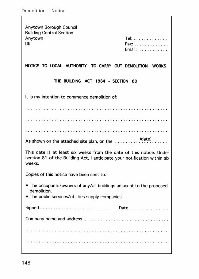
148
Demolition -- Notice
Demolition ~ skilled and potentially dangerous work that should
only be undertaken by experienced contractors.
Types of demolition ~ partial or complete removal. Partial is less
dynamic than complete removal, requiring temporary support to
the remaining structure. This may involve window strutting, floor
props and shoring. The execution of work is likely to be limited to
manual handling with minimal use of powered equipment.
Preliminaries ~ a detailed survey should include:
• an assessment of condition of the structure and the impact of
removing parts on the remainder.
• the effect demolition will have on adjacent properties.
• photographic records, particularly of any noticeable defects on
adjacent buildings.
• neighbourhood impact, ie. disruption, disturbance, protection.
• the need for hoardings, see pages 85 to 89.
• potential for salvaging/recycling/re-use of materials.
• extent of basements and tunnels.
• services † need to terminate and protect for future
reconnections.
• means for selective removal of hazardous materials.
Insurance ~ general builders are unlikely to find demolition cover in
their standard policies. All risks indemnity should be considered to
cover claims from site personnel and others accessing the site.
Additional third party cover will be required for claims for loss or
damage to other property, occupied areas, business, utilities,
private and public roads.
Salvage ~ salvaged materials and components can be valuable,
bricks, tiles, slates, steel sections and timber are all marketable.
Architectural features such as fireplaces and stairs will command a
good price. Reclamation costs will be balanced against the
financial gain.
Asbestos ~ this banned material has been used in a variety of
applications including pipe insulation, fire protection, sheet
claddings, linings and roofing. Samples should be taken for
laboratory analysis and if necessary, specialist contractors
engaged to remove material before demolition commences.
149
Demolition
Generally ~ the reverse order of construction to gradually reduce
the height. Where space in not confined, overturning or explosives
may be considered.
Piecemeal ~ use of hand held equipment such as pneumatic
breakers, oxy-acetylene cutters, picks and hammers. Care should be
taken when salvaging materials and other reusable components.
Chutes should be used to direct debris to a suitable place of
collection (see page 169).
Pusher Arm ~ usually attached to a long reach articulated boom
fitted to a tracked chassis. Hydraulic movement is controlled from
a robust cab structure mounted above the tracks.
Wrecking Ball ~ largely confined to history, as even with safety
features such as anti-spin devices, limited control over a heavy
weight swinging and slewing from a crane jib will be considered
unsafe in many situations.
Impact Hammer ~ otherwise known as a ``pecker''. Basically a large
chisel operated by pneumatic power and fitted to the end of an
articulated boom on a tracked chassis.
Nibbler ~ a hydraulically operated grip fitted as above that can be
rotated to break brittle materials such as concrete.
Overturning ~ steel wire ropes of at least 38 mm diameter
attached at high level and to an anchored winch or heavy vehicle.
May be considered where controlled collapse is encouraged by
initial removal of key elements of structure, typical of steel framed
buildings. Alternative methods should be given preference.
Explosives ~ demolition is specialised work and the use of
explosives in demolition is a further specialised practice limited to
very few licensed operators. Charges are set to fire in a sequence
that weakens the building to a controlled internal collapse.
Some additional references ~
BS 6187: Code of practice for demolition.
The Construction (Health, Safety and Welfare) Regulations.
The Management of Health and Safety at Work Regulations.
Demolition -- Methods
150
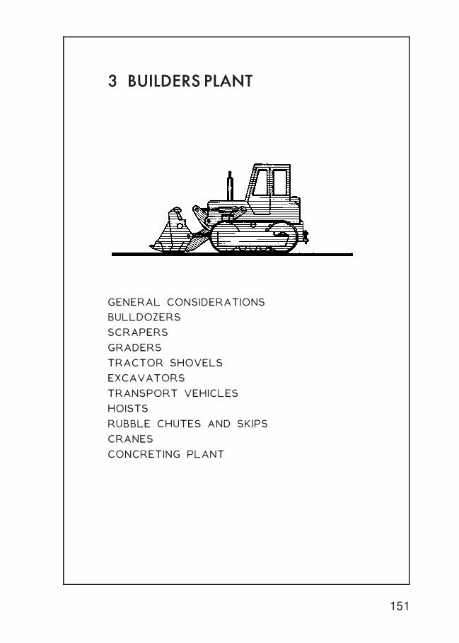
3 BUILDERS PLANT
GENERAL CONSIDERATIONS
BULLDOZERS
SCRAPERS
GRADERS
TRACTOR SHOVELS
EXCAVATORS
TRANSPORT VEHICLES
HOISTS
RUBBLE CHUTES AND SKIPS
CRANES
CONCRETING PLANT
151
General Considerations ~ items of builders plant ranging from small
hand held power tools to larger pieces of plant such as mechanical
excavators and tower cranes can be considered for use for one or
more of the following reasons:-
1 . Increased production.
2. Reduction in overall construction costs.
3. Carry out activities which cannot be carried out by the
traditional manual methods in the context of economics.
4. Eliminate heavy manual work thus reducing fatigue and as a
consequence increasing productivity.
5. Replacing labour where there is a shortage of personnel with
the necessary skills.
6. Maintain the high standards required particularly in the
context of structural engineering works.
Economic Considerations ~ the introduction of plant does not
always result in economic savings since extra temporary site works
such as roadworks, hardstandings, foundations and anchorages may
have to be provided at a cost which is in excess of the savings
made by using the plant. The site layout and circulation may have
to be planned around plant positions and movements rather than
around personnel and material movements and accommodation. To
be economic plant must be fully utilised and not left standing idle
since plant, whether hired or owned, will have to be paid for even
if it is non-productive. Full utilisation of plant is usually considered
to be in the region of 85% of on site time, thus making an
allowance for routine, daily and planned maintenance which needs
to be carried out to avoid as far as practicable plant breakdowns
which could disrupt the construction programme. Many pieces of
plant work in conjunction with other items of plant such as
excavators and their attendant haulage vehicles therefore a
correct balance of such plant items must be obtained to achieve
an economic result.
Maintenance Considerations ~ on large contracts where a number
of plant items are to be used it may be advantageous to employ a
skilled mechanic to be on site to carry out all the necessary daily,
preventive and planned maintenance tasks together with any
running repairs which could be carried out on site.
152
Builders Plant
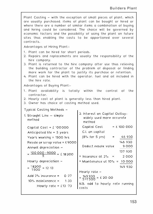
Plant Costing ~ with the exception of small pieces of plant, which
are usually purchased, items of plant can be bought or hired or
where there are a number of similar items a combination of buying
and hiring could be considered. The choice will be governed by
economic factors and the possibility of using the plant on future
sites thus enabling the costs to be apportioned over several
contracts.
Advantages of Hiring Plant:-
1 . Plant can be hired for short periods.
2. Repairs and replacements are usually the responsibility of the
hire company.
3. Plant is returned to the hire company after use thus relieving
the building contractor of the problem of disposal or finding
more work for the plant to justify its purchase or retention.
4. Plant can be hired with the operator, fuel and oil included in
the hire rate.
Advantages of Buying Plant:-
1 . Plant availability is totally within the control of the
contractor.
2. Hourly cost of plant is generally less than hired plant.
3. Owner has choice of costing method used.
153
Builders Plant
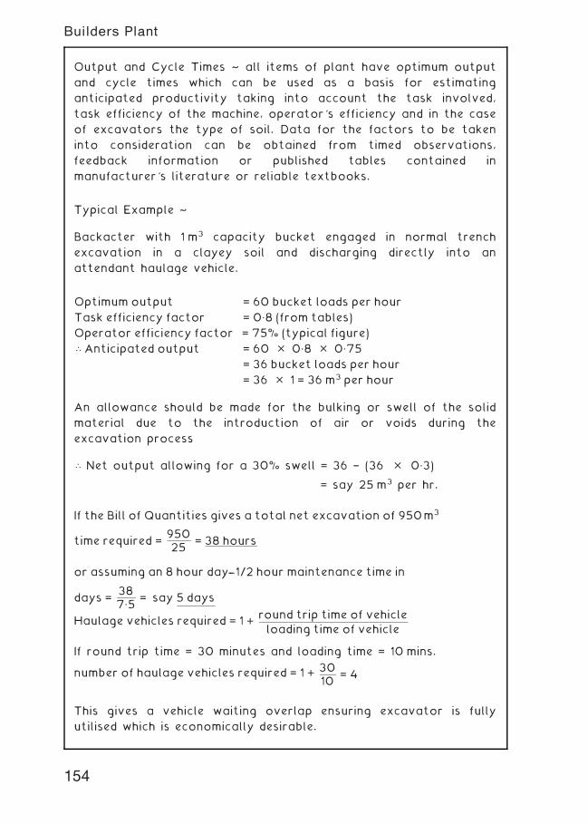
Output and Cycle Times ~ all items of plant have optimum output
and cycle times which can be used as a basis for estimating
anticipated productivity taking into account the task involved,
task efficiency of the machine, operator's efficiency and in the case
of excavators the type of soil. Data for the factors to be taken
into consideration can be obtained from timed observations,
feedback information or published tables contained in
manufacturer's literature or reliable textbooks.
Typical Example ~
Backacter with 1 m3 capacity bucket engaged in normal trench
excavation in a clayey soil and discharging directly into an
attendant haulage vehicle.
An allowance should be made for the bulking or swell of the solid
material due to the introduction of air or voids during the
excavation process
\ Net output allowing for a 30% swell = 36 † (36 � 0„3)
= say 25 m3 per hr.
If the Bill of Quantities gives a total net excavation of 950m3
time required =95025
= 38 hours
or assuming an 8 hour day---1/2 hour maintenance time in
days =387„5
= say 5 days
Haulage vehicles required = 1 +round trip time of vehicle
loading time of vehicle
If round trip time = 30 minutes and loading time = 10 mins.
number of haulage vehicles required = 1 +3010
= 4
This gives a vehicle waiting overlap ensuring excavator is fully
utilised which is economically desirable.
Optimum output = 60 bucket loads per hour
Task efficiency factor = 0„8 (from tables)
Operator efficiency factor = 75% (typical figure)
\ Anticipated output = 60 � 0„8 � 0„75
= 36 bucket loads per hour
= 36 � 1 = 36 m3 per hour
154
Builders Plant
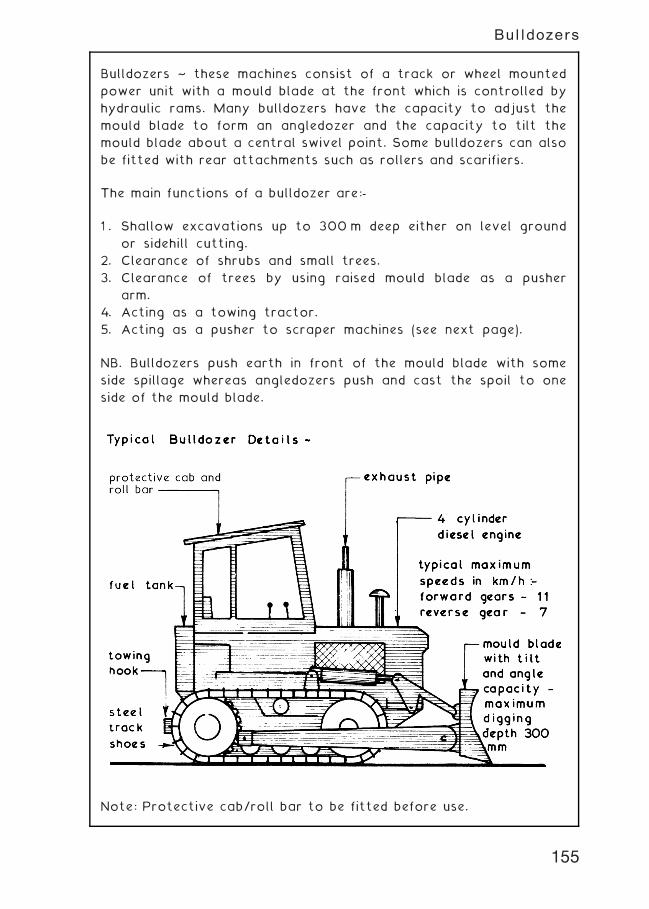
Bulldozers ~ these machines consist of a track or wheel mounted
power unit with a mould blade at the front which is controlled by
hydraulic rams. Many bulldozers have the capacity to adjust the
mould blade to form an angledozer and the capacity to tilt the
mould blade about a central swivel point. Some bulldozers can also
be fitted with rear attachments such as rollers and scarifiers.
The main functions of a bulldozer are:-
1 . Shallow excavations up to 300 m deep either on level ground
or sidehill cutting.
2. Clearance of shrubs and small trees.
3. Clearance of trees by using raised mould blade as a pusher
arm.
4. Acting as a towing tractor.
5. Acting as a pusher to scraper machines (see next page).
NB. Bulldozers push earth in front of the mould blade with some
side spillage whereas angledozers push and cast the spoil to one
side of the mould blade.
Note: Protective cab/roll bar to be fitted before use.
155
Bulldozers
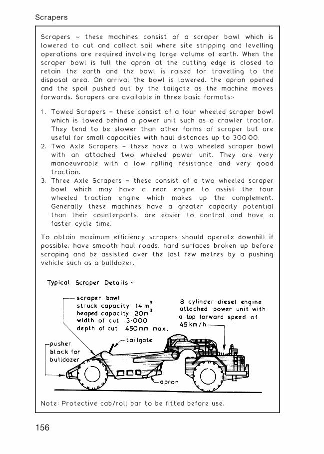
Scrapers ~ these machines consist of a scraper bowl which is
lowered to cut and collect soil where site stripping and levelling
operations are required involving large volume of earth. When the
scraper bowl is full the apron at the cutting edge is closed to
retain the earth and the bowl is raised for travelling to the
disposal area. On arrival the bowl is lowered, the apron opened
and the spoil pushed out by the tailgate as the machine moves
forwards. Scrapers are available in three basic formats:-
1 . Towed Scrapers † these consist of a four wheeled scraper bowl
which is towed behind a power unit such as a crawler tractor.
They tend to be slower than other forms of scraper but are
useful for small capacities with haul distances up to 300�00.
2. Two Axle Scrapers † these have a two wheeled scraper bowl
with an attached two wheeled power unit. They are very
manoeuvrable with a low rolling resistance and very good
traction.
3. Three Axle Scrapers † these consist of a two wheeled scraper
bowl which may have a rear engine to assist the four
wheeled traction engine which makes up the complement.
Generally these machines have a greater capacity potential
than their counterparts, are easier to control and have a
faster cycle time.
To obtain maximum efficiency scrapers should operate downhill if
possible, have smooth haul roads, hard surfaces broken up before
scraping and be assisted over the last few metres by a pushing
vehicle such as a bulldozer.
Note: Protective cab/roll bar to be fitted before use.
156
Scrapers
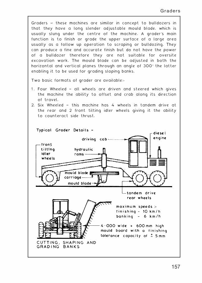
Graders ~ these machines are similar in concept to bulldozers in
that they have a long slender adjustable mould blade, which is
usually slung under the centre of the machine. A grader's main
function is to finish or grade the upper surface of a large area
usually as a follow up operation to scraping or bulldozing. They
can produce a fine and accurate finish but do not have the power
of a bulldozer therefore they are not suitable for oversite
excavation work. The mould blade can be adjusted in both the
horizontal and vertical planes through an angle of 300� the latter
enabling it to be used for grading sloping banks.
Two basic formats of grader are available:-
1 . Four Wheeled † all wheels are driven and steered which gives
the machine the ability to offset and crab along its direction
of travel.
2. Six Wheeled † this machine has 4 wheels in tandem drive at
the rear and 2 front tilting idler wheels giving it the ability
to counteract side thrust.
157
Graders
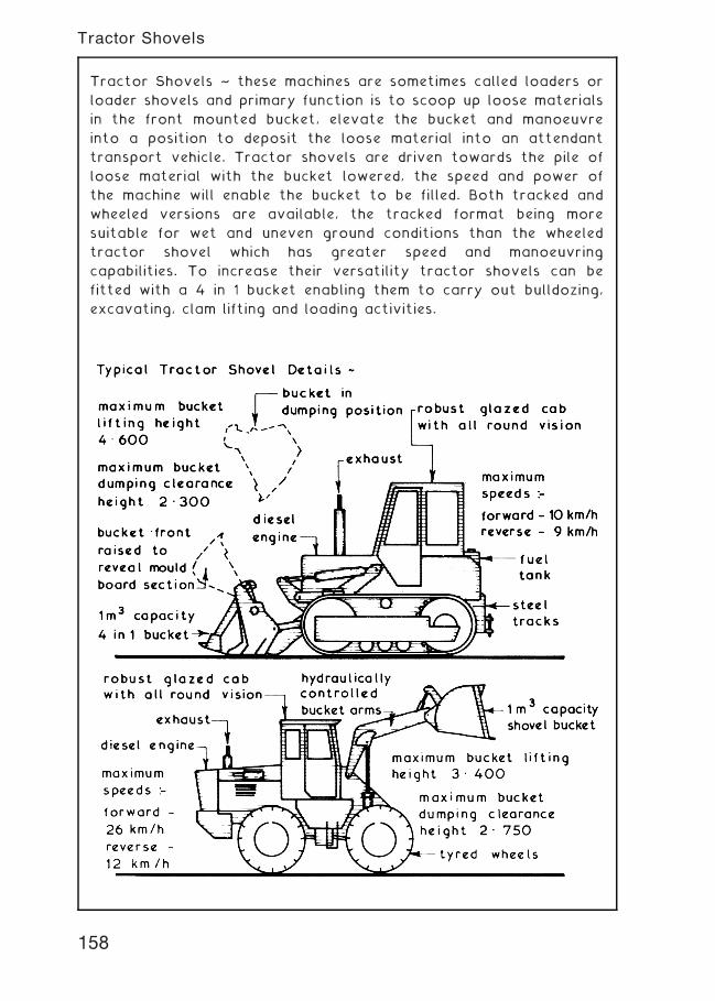
Tractor Shovels ~ these machines are sometimes called loaders or
loader shovels and primary function is to scoop up loose materials
in the front mounted bucket, elevate the bucket and manoeuvre
into a position to deposit the loose material into an attendant
transport vehicle. Tractor shovels are driven towards the pile of
loose material with the bucket lowered, the speed and power of
the machine will enable the bucket to be filled. Both tracked and
wheeled versions are available, the tracked format being more
suitable for wet and uneven ground conditions than the wheeled
tractor shovel which has greater speed and manoeuvring
capabilities. To increase their versatility tractor shovels can be
fitted with a 4 in 1 bucket enabling them to carry out bulldozing,
excavating, clam lifting and loading activities.
158
Tractor Shovels
Excavating Machines ~ these are one of the major items of
builders plant and are used primarily to excavate and load most
types of soil. Excavating machines come in a wide variety of
designs and sizes but all of them can be placed within one of three
categories:-
1. Universal Excavators † this category covers most forms of
excavators all of which have a common factor the power
unit. The universal power unit is a tracked based machine
with a slewing capacity of 360� and by altering the boom
arrangement and bucket type different excavating functions
can be obtained. These machines are selected for high output
requirements and are rope controlled.
2. Purpose Designed Excavators † these are machines which
have been designed specifically to carry out one mode of
excavation and they usually have smaller bucket capacities
than universal excavators; they are hydraulically controlled
with a shorter cycle time.
3. Multi-purpose Excavators † these machines can perform
several excavating functions having both front and rear
attachments. They are designed to carry out small excavation
operations of low output quickly and efficiently. Multi-purpose
excavators can be obtained with a wheeled or tracked base
and are ideally suited for a small building firm with low
excavation plant utilisation requirements.
Skimmers ~ these excavators are rigged using a universal power
unit for surface stripping and shallow excavation work up to
300 mm deep where a high degree of accuracy is required. They
usually require attendant haulage vehicles to remove the spoil and
need to be transported between sites on a low-loader. Because of
their limitations and the alternative machines available they are
seldom used today.
159
Excavators
Face Shovels ~ the primary function of this piece of plant is to
excavate above its own track or wheel level. They are available as
a universal power unit based machine or as a hydraulic purpose
designed unit. These machines can usually excavate any type of
soil except rock which needs to be loosened, usually by blasting,
prior to excavation. Face shovels generally require attendant
haulage vehicles for the removal of spoil and a low loader
transport lorry for travel between sites. Most of these machines
have a limited capacity of between 300 and 400 mm for
excavation below their own track or wheel level.
160
Excavators
Backacters ~ these machines are suitable for trench, foundation
and basement excavations and are available as a universal power
unit base machine or as a purpose designed hydraulic unit. They
can be used with or without attendant haulage vehicles since the
spoil can be placed alongside the excavation for use in backfilling.
These machines will require a low loader transport vehicle for
travel between sites. Backacters used in trenching operations with
a bucket width equal to the trench width can be very accurate
with a high output rating.
161
Excavators
Draglines ~ these machines are based on the universal power unit
with basic crane rigging to which is attached a drag bucket. The
machine is primarily designed for bulk excavation in loose soils up
to 3„000 below its own track level by swinging the bucket out to
the excavation position and hauling or dragging it back towards
the power unit. Dragline machines can also be fitted with a grab or
clamshell bucket for excavating in very loose soils.
162
Excavators
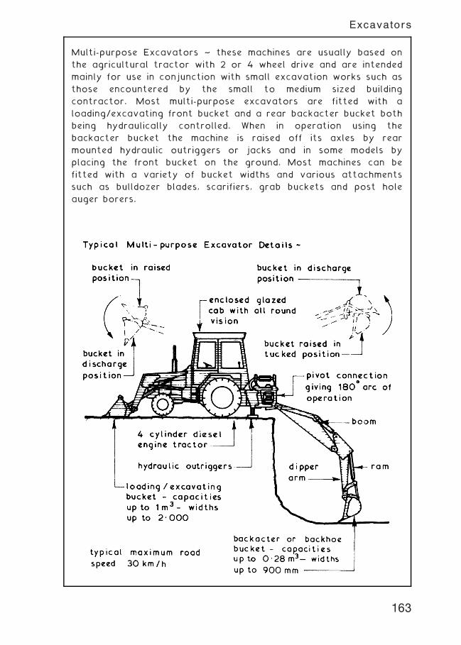
Multi-purpose Excavators ~ these machines are usually based on
the agricultural tractor with 2 or 4 wheel drive and are intended
mainly for use in conjunction with small excavation works such as
those encountered by the small to medium sized building
contractor. Most multi-purpose excavators are fitted with a
loading/excavating front bucket and a rear backacter bucket both
being hydraulically controlled. When in operation using the
backacter bucket the machine is raised off its axles by rear
mounted hydraulic outriggers or jacks and in some models by
placing the front bucket on the ground. Most machines can be
fitted with a variety of bucket widths and various attachments
such as bulldozer blades, scarifiers, grab buckets and post hole
auger borers.
163
Excavators
Transport Vehicles ~ these can be defined as vehicles whose
primary function is to convey passengers and/or materials between
and around building sites. The types available range from the
conventional saloon car to the large low loader lorries designed to
transport other items of builders plant between construction sites
and the plant yard or depot.
Vans † these transport vehicles range from the small two person
plus a limited amount of materials to the large vans with purpose
designed bodies such as those built to carry large sheets of glass.
Most small vans are usually fitted with a petrol engine and are
based on the manufacturer's standard car range whereas the
larger vans are purpose designed with either petrol or diesel
engines. These basic designs can usually be supplied with an
uncovered tipping or non-tipping container mounted behind the
passenger cab for use as a `pick-up' truck.
Passenger Vehicles † these can range from a simple framed cabin
which can be placed in the container of a small lorry or `pick-up'
truck to a conventional bus or coach. Vans can also be designed
to carry a limited number of seated passengers by having fixed or
removable seating together with windows fitted in the van sides
thus giving the vehicle a dual function. The number of passengers
carried can be limited so that the driver does not have to hold a
PSV (public service vehicle) licence.
Lorries † these are sometimes referred to as haul vehicles and are
available as road or site only vehicles. Road haulage vehicles have
to comply with all the requirements of the Road Traffic Acts which
among other requirements limits size and axle loads. The off-
highway or site only lorries are not so restricted and can be
designed to carry two to three times the axle load allowed on the
public highway. Site only lorries are usually specially designed to
traverse and withstand the rough terrain encountered on many
construction sites. Lorries are available as non-tipping, tipping and
special purpose carriers such as those with removable skips and
those equipped with self loading and unloading devices. Lorries
specifically designed for the transportation of large items of plant
are called low loaders and are usually fitted with integral or
removable ramps to facilitate loading and some have a winching
system to haul the plant onto the carrier platform.
164
Transport Vehicles
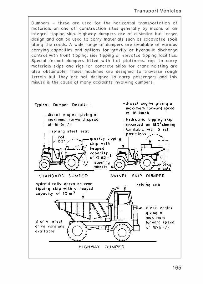
Dumpers ~ these are used for the horizontal transportation of
materials on and off construction sites generally by means of an
integral tipping skip. Highway dumpers are of a similar but larger
design and can be used to carry materials such as excavated spoil
along the roads. A wide range of dumpers are available of various
carrying capacities and options for gravity or hydraulic discharge
control with front tipping, side tipping or elevated tipping facilities.
Special format dumpers fitted with flat platforms, rigs to carry
materials skips and rigs for concrete skips for crane hoisting are
also obtainable. These machines are designed to traverse rough
terrain but they are not designed to carry passengers and this
misuse is the cause of many accidents involving dumpers.
165
Transport Vehicles
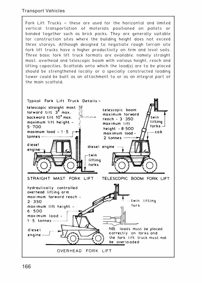
Fork Lift Trucks ~ these are used for the horizontal and limited
vertical transportation of materials positioned on pallets or
banded together such as brick packs. They are generally suitable
for construction sites where the building height does not exceed
three storeys. Although designed to negotiate rough terrain site
fork lift trucks have a higher productivity on firm and level soils.
Three basic fork lift truck formats are available, namely straight
mast, overhead and telescopic boom with various height, reach and
lifting capacities. Scaffolds onto which the load(s) are to be placed
should be strengthened locally or a specially constructed loading
tower could be built as an attachment to or as an integral part of
the main scaffold.
166
Transport Vehicles
Hoists ~ these are designed for the vertical transportation of
materials, passengers or materials and passengers (see page 168).
Materials hoists are designed for one specific use (i.e. the vertical
transportation of materials) and under no circumstances should
they be used to transport passengers. Most material hoists are of
a mobile format which can be dismantled, folded onto the chassis
and moved to another position or site under their own power or
towed by a haulage vehicle. When in use material hoists need to be
stabilised and/or tied to the structure and enclosed with a
protective screen.
167
Hoists
Passenger Hoists ~ these are designed to carry passengers
although most are capable of transporting a combined load of
materials and passengers within the lifting capacity of the hoist. A
wide selection of hoists are available ranging from a single cage
with rope suspension to twin cages with rack and pinion operation
mounted on two sides of a static tower.
168
Hoists
Rubble Chutes ~ these apply to contracts involving demolition,
repair, maintenance and refurbishment. The simple concept of
connecting several perforated dustbins is reputed to have been
conceived by an ingenious site operative for the expedient and safe
conveyance of materials.
In purpose designed format, the tapered cylinders are produced
from reinforced rubber with chain linkage for continuity. Overall
unit lengths are generally 1100 mm, providing an effective length of
1 m. Hoppers and side entry units are made for special applications.
Ref. Highways Act † written permit (license) must be obtained from
the local authority highways department for use of a skip on a
public thoroughfare. It will have to be illuminated at night and may
require a temporary traffic light system to regulate vehicles.
169
Rubble Chutes and Skips
Cranes ~ these are lifting devices designed to raise materials by
means of rope operation and move the load horizontally within the
limitations of any particular machine. The range of cranes available
is very wide and therefore choice must be based on the loads to be
lifted, height and horizontal distance to be covered, time period(s)
of lifting operations, utilisation factors and degree of mobility
required. Crane types can range from a simple rope and pulley or
gin wheel to a complex tower crane but most can be placed within
1 of 3 groups, namely mobile, static and tower cranes.
170
Cranes
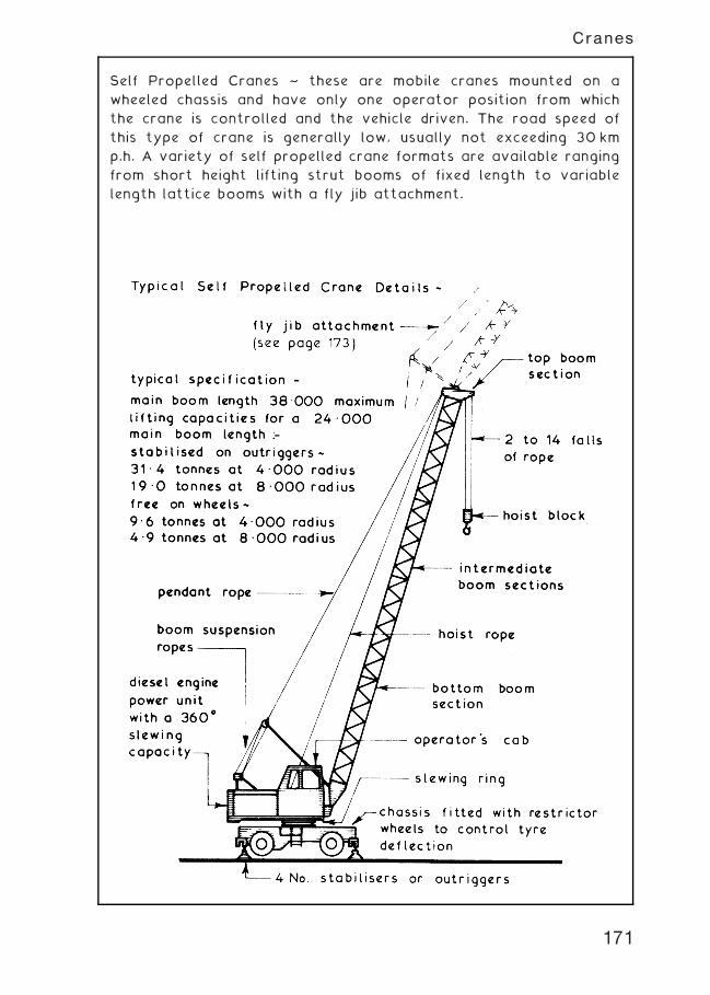
Self Propelled Cranes ~ these are mobile cranes mounted on a
wheeled chassis and have only one operator position from which
the crane is controlled and the vehicle driven. The road speed of
this type of crane is generally low, usually not exceeding 30 km
p.h. A variety of self propelled crane formats are available ranging
from short height lifting strut booms of fixed length to variable
length lattice booms with a fly jib attachment.
171
Cranes
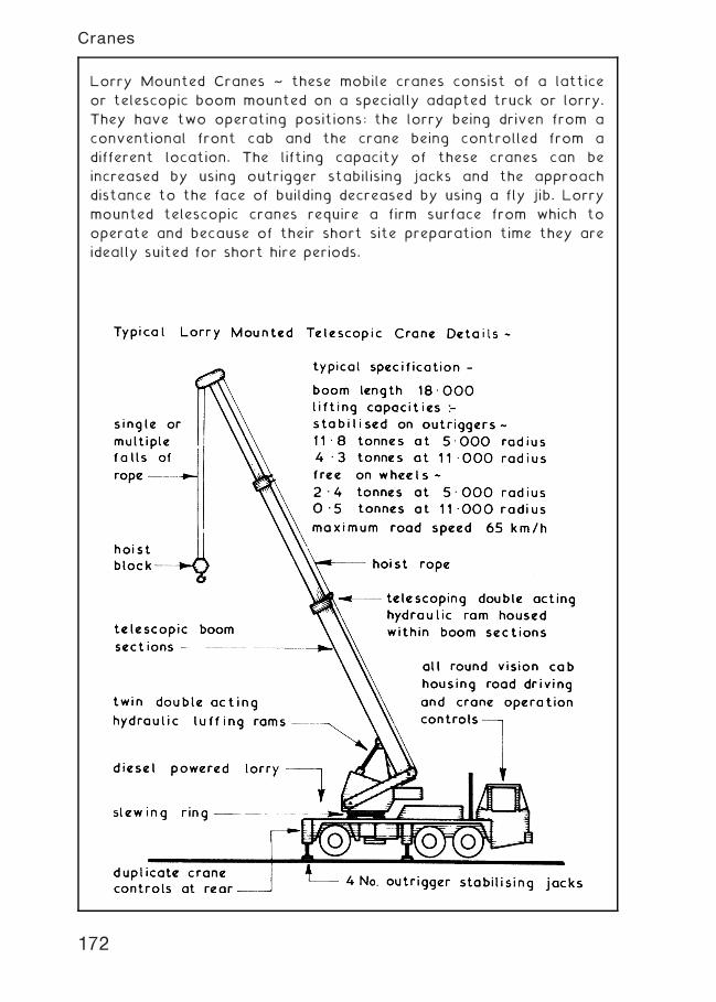
Lorry Mounted Cranes ~ these mobile cranes consist of a lattice
or telescopic boom mounted on a specially adapted truck or lorry.
They have two operating positions: the lorry being driven from a
conventional front cab and the crane being controlled from a
different location. The lifting capacity of these cranes can be
increased by using outrigger stabilising jacks and the approach
distance to the face of building decreased by using a fly jib. Lorry
mounted telescopic cranes require a firm surface from which to
operate and because of their short site preparation time they are
ideally suited for short hire periods.
172
Cranes
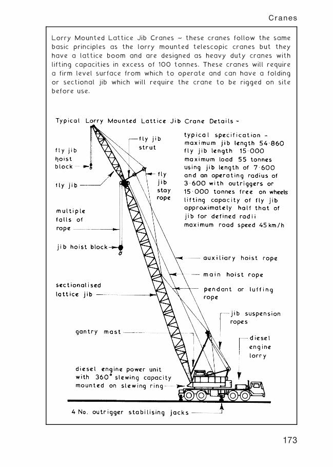
Lorry Mounted Lattice Jib Cranes ~ these cranes follow the same
basic principles as the lorry mounted telescopic cranes but they
have a lattice boom and are designed as heavy duty cranes with
lifting capacities in excess of 100 tonnes. These cranes will require
a firm level surface from which to operate and can have a folding
or sectional jib which will require the crane to be rigged on site
before use.
173
Cranes
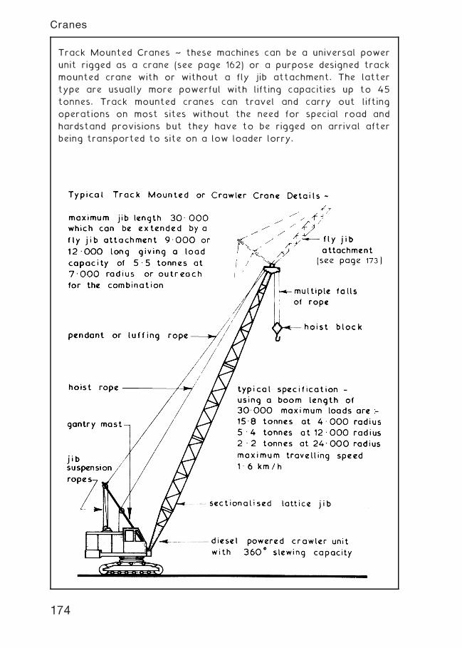
Track Mounted Cranes ~ these machines can be a universal power
unit rigged as a crane (see page 162) or a purpose designed track
mounted crane with or without a fly jib attachment. The latter
type are usually more powerful with lifting capacities up to 45
tonnes. Track mounted cranes can travel and carry out lifting
operations on most sites without the need for special road and
hardstand provisions but they have to be rigged on arrival after
being transported to site on a low loader lorry.
174
Cranes
Gantry Cranes ~ these are sometimes called portal cranes and
consist basically of two `A' frames joined together with a cross
member on which transverses the lifting appliance. In small gantry
cranes (up to 10 tonnes lifting capacity) the `A' frames are usually
wheel mounted and manually propelled whereas in the large gantry
cranes (up to 100 tonnes lifting capacity) the `A' frames are
mounted on powered bogies running on rail tracks with the driving
cab and lifting gear mounted on the cross beam or gantry. Small
gantry cranes are used primarily for loading and unloading
activities in stock yards whereas the medium and large gantry
cranes are used to straddle the work area such as in power
station construction or in repetitive low to medium rise
developments. All gantry cranes have the advantage of three
direction movement †
1 . Transverse by moving along the cross beam.
2. Vertical by raising and lowering the hoist block.
3. Horizontal by forward and reverse movements of the whole
gantry crane.
175
Cranes
Mast Cranes ~ these are similar in appearance to the familiar
tower cranes but they have one major difference in that the mast
or tower is mounted on the slewing ring and thus rotates whereas
a tower crane has the slewing ring at the top of the tower and
therefore only the jib portion rotates. Mast cranes are often
mobile, self erecting, of relatively low lifting capacity and are
usually fitted with a luffing jib. A wide variety of models are
available and have the advantage over most mobile low pivot
cranes of a closer approach to the face of the building.
176
Cranes
Tower Cranes ~ most tower cranes have to be assembled and
erected on site prior to use and can be equipped with a horizontal
or luffing jib. The wide range of models available often make it
difficult to choose a crane suitable for any particular site but most
tower cranes can be classified into one of four basic groups thus:-
1. Self Supporting Static Tower Cranes † high lifting capacity
with the mast or tower fixed to a foundation base † they
are suitable for confined and open sites. (see page 178)
2. Supported Static Tower Cranes † similar in concept to self
supporting cranes and are used where high lifts are required,
the mast or tower being tied at suitable intervals to the
structure to give extra stability. (see page 179)
3. Travelling Tower Cranes † these are tower cranes mounted
on power bogies running on a wide gauge railway track to
give greater site coverage † only slight gradients can be
accommodated therefore a reasonably level site or specially
constructed railway support trestle is required. (see page 180)
4. Climbing Cranes † these are used in conjunction with tall buildings
and structures. The climbing mast or tower is housed within the
structure and raised as the height of the structure is increased.
Upon completion the crane is dismantled into small sections and
lowered down the face of the building. (see page 181)
All tower cranes should be left in an `out of service' condition
when unattended and in high wind conditions, the latter varying
with different models but generally wind speeds in excess of 60 km
p.h. would require the crane to be placed in an out of service
condition thus:-
177
Cranes
178
Cranes
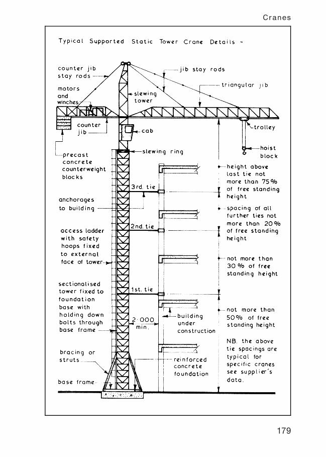
179
Cranes
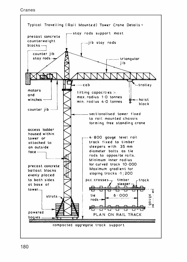
180
Cranes
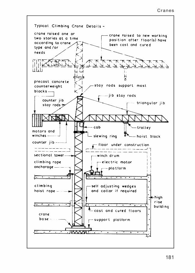
181
Cranes
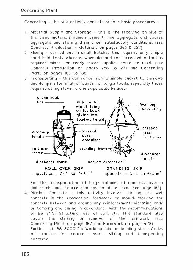
Concreting ~ this site activity consists of four basic procedures †
1 . Material Supply and Storage † this is the receiving on site of
the basic materials namely cement, fine aggregate and coarse
aggregate and storing them under satisfactory conditions. (see
Concrete Production † Materials on pages 266 & 267)
2. Mixing † carried out in small batches this requires only simple
hand held tools whereas when demand for increased output is
required mixers or ready mixed supplies could be used. (see
Concrete Production on pages 268 to 271 and Concreting
Plant on pages 183 to 188)
3. Transporting † this can range from a simple bucket to barrows
and dumpers for small amounts. For larger loads, especially those
required at high level, crane skips could be used:-
For the transportation of large volumes of concrete over a
limited distance concrete pumps could be used. (see page 186)
4. Placing Concrete † this activity involves placing the wet
concrete in the excavation, formwork or mould; working the
concrete between and around any reinforcement; vibrating and/
or tamping and curing in accordance with the recommendations
of BS 8110: Structural use of concrete. This standard also
covers the striking or removal of the formwork. (see
Concreting Plant on page 187 and Formwork on page 478)
Further ref. BS 8000-2.1: Workmanship on building sites. Codes
of practice for concrete work. Mixing and transporting
concrete.
182
Concreting Plant
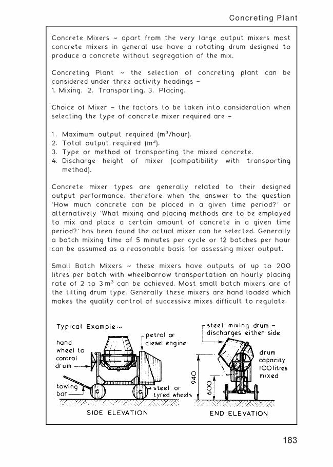
Concrete Mixers ~ apart from the very large output mixers most
concrete mixers in general use have a rotating drum designed to
produce a concrete without segregation of the mix.
Concreting Plant ~ the selection of concreting plant can be
considered under three activity headings †
1. Mixing. 2. Transporting. 3. Placing.
Choice of Mixer ~ the factors to be taken into consideration when
selecting the type of concrete mixer required are †
1 . Maximum output required (m3/hour).
2. Total output required (m3).
3. Type or method of transporting the mixed concrete.
4. Discharge height of mixer (compatibility with transporting
method).
Concrete mixer types are generally related to their designed
output performance, therefore when the answer to the question
`How much concrete can be placed in a given time period?' or
alternatively `What mixing and placing methods are to be employed
to mix and place a certain amount of concrete in a given time
period?' has been found the actual mixer can be selected. Generally
a batch mixing time of 5 minutes per cycle or 12 batches per hour
can be assumed as a reasonable basis for assessing mixer output.
Small Batch Mixers ~ these mixers have outputs of up to 200
litres per batch with wheelbarrow transportation an hourly placing
rate of 2 to 3 m3 can be achieved. Most small batch mixers are of
the tilting drum type. Generally these mixers are hand loaded which
makes the quality control of successive mixes difficult to regulate.
183
Concreting Plant
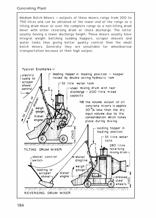
Medium Batch Mixers ~ outputs of these mixers range from 200 to
750 litres and can be obtained at the lower end of the range as a
tilting drum mixer or over the complete range as a non-tilting drum
mixer with either reversing drum or chute discharge. The latter
usually having a lower discharge height. These mixers usually have
integral weight batching loading hoppers, scraper shovels and
water tanks thus giving better quality control than the small
batch mixers. Generally they are unsuitable for wheelbarrow
transportation because of their high output.
184
Concreting Plant
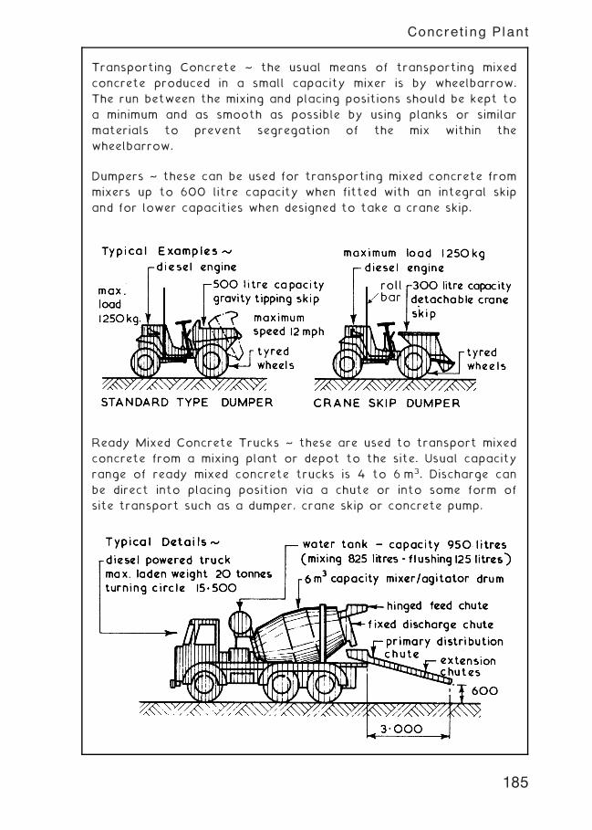
Transporting Concrete ~ the usual means of transporting mixed
concrete produced in a small capacity mixer is by wheelbarrow.
The run between the mixing and placing positions should be kept to
a minimum and as smooth as possible by using planks or similar
materials to prevent segregation of the mix within the
wheelbarrow.
Dumpers ~ these can be used for transporting mixed concrete from
mixers up to 600 litre capacity when fitted with an integral skip
and for lower capacities when designed to take a crane skip.
Ready Mixed Concrete Trucks ~ these are used to transport mixed
concrete from a mixing plant or depot to the site. Usual capacity
range of ready mixed concrete trucks is 4 to 6 m3. Discharge can
be direct into placing position via a chute or into some form of
site transport such as a dumper, crane skip or concrete pump.
185
Concreting Plant
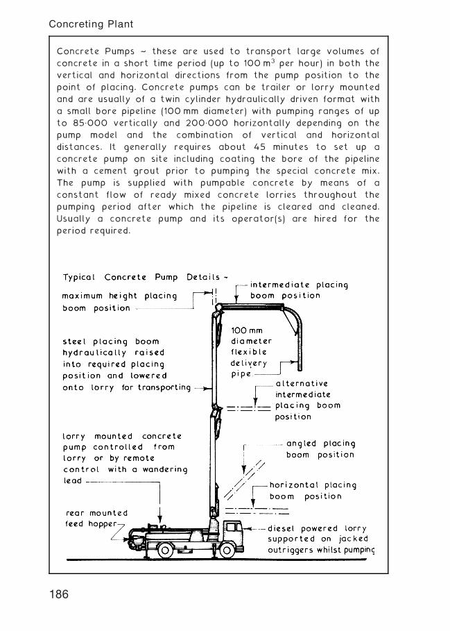
Concrete Pumps ~ these are used to transport large volumes of
concrete in a short time period (up to 100 m3 per hour) in both the
vertical and horizontal directions from the pump position to the
point of placing. Concrete pumps can be trailer or lorry mounted
and are usually of a twin cylinder hydraulically driven format with
a small bore pipeline (100 mm diameter) with pumping ranges of up
to 85„000 vertically and 200„000 horizontally depending on the
pump model and the combination of vertical and horizontal
distances. It generally requires about 45 minutes to set up a
concrete pump on site including coating the bore of the pipeline
with a cement grout prior to pumping the special concrete mix.
The pump is supplied with pumpable concrete by means of a
constant flow of ready mixed concrete lorries throughout the
pumping period after which the pipeline is cleared and cleaned.
Usually a concrete pump and its operator(s) are hired for the
period required.
186
Concreting Plant
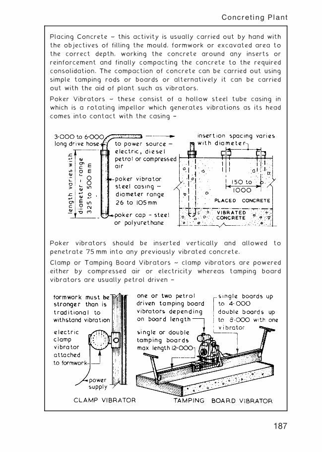
Placing Concrete ~ this activity is usually carried out by hand with
the objectives of filling the mould, formwork or excavated area to
the correct depth, working the concrete around any inserts or
reinforcement and finally compacting the concrete to the required
consolidation. The compaction of concrete can be carried out using
simple tamping rods or boards or alternatively it can be carried
out with the aid of plant such as vibrators.
Poker Vibrators ~ these consist of a hollow steel tube casing in
which is a rotating impellor which generates vibrations as its head
comes into contact with the casing †
Poker vibrators should be inserted vertically and allowed to
penetrate 75 mm into any previously vibrated concrete.
Clamp or Tamping Board Vibrators ~ clamp vibrators are powered
either by compressed air or electricity whereas tamping board
vibrators are usually petrol driven †
187
Concreting Plant
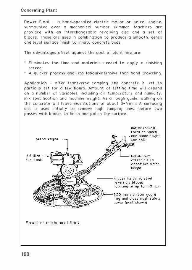
Power Float † a hand-operated electric motor or petrol engine,
surmounted over a mechanical surface skimmer. Machines are
provided with an interchangeable revolving disc and a set of
blades. These are used in combination to produce a smooth, dense
and level surface finish to in-situ concrete beds.
The advantages offset against the cost of plant hire are:
* Eliminates the time and materials needed to apply a finishing
screed.
* A quicker process and less labour-intensive than hand troweling.
Application † after transverse tamping, the concrete is left to
partially set for a few hours. Amount of setting time will depend
on a number of variables, including air temperature and humidity,
mix specification and machine weight. As a rough guide, walking on
the concrete will leave indentations of about 3†4 mm. A surfacing
disc is used initially to remove high tamping lines, before two
passes with blades to finish and polish the surface.
188
Concreting Plant
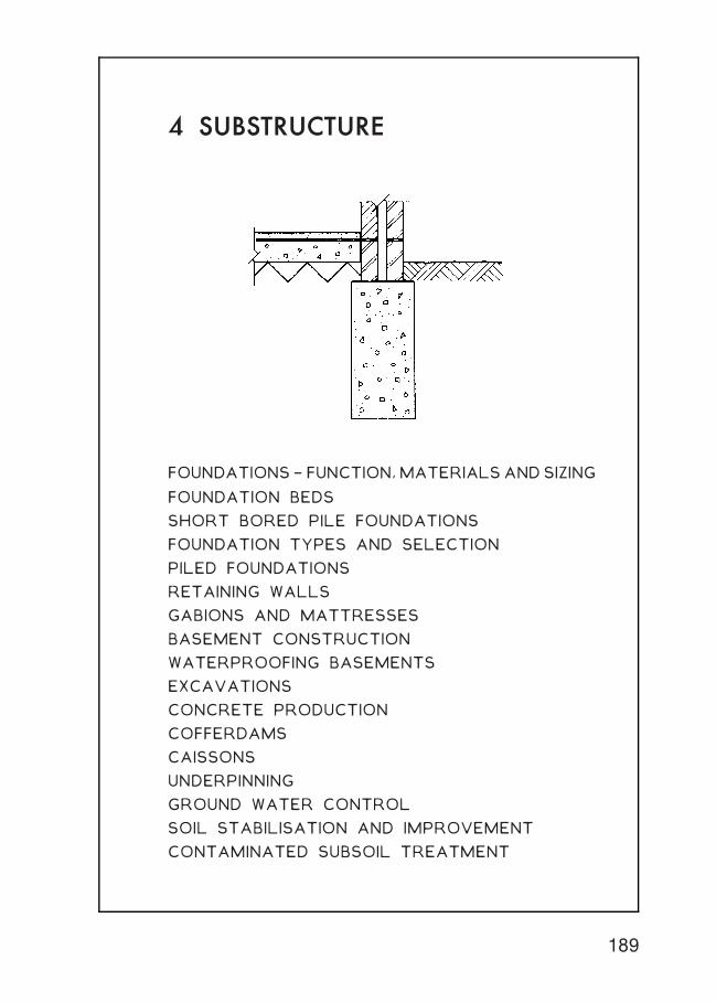
4 SUBSTRUCTURE
FOUNDATIONS† FUNCTION,MATERIALSANDSIZING
FOUNDATION BEDS
SHORT BORED PILE FOUNDATIONS
FOUNDATION TYPES AND SELECTION
PILED FOUNDATIONS
RETAINING WALLS
GABIONS AND MATTRESSES
BASEMENT CONSTRUCTION
WATERPROOFING BASEMENTS
EXCAVATIONS
CONCRETE PRODUCTION
COFFERDAMS
CAISSONS
UNDERPINNING
GROUND WATER CONTROL
SOIL STABILISATION AND IMPROVEMENT
CONTAMINATED SUBSOIL TREATMENT
189
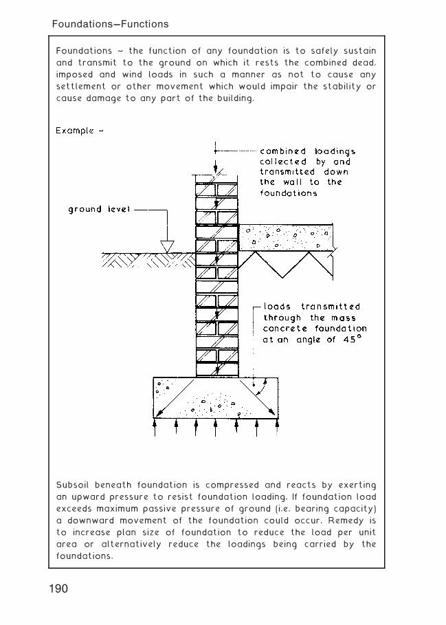
Foundations ~ the function of any foundation is to safely sustain
and transmit to the ground on which it rests the combined dead,
imposed and wind loads in such a manner as not to cause any
settlement or other movement which would impair the stability or
cause damage to any part of the building.
Subsoil beneath foundation is compressed and reacts by exerting
an upward pressure to resist foundation loading. If foundation load
exceeds maximum passive pressure of ground (i.e. bearing capacity)
a downward movement of the foundation could occur. Remedy is
to increase plan size of foundation to reduce the load per unit
area or alternatively reduce the loadings being carried by the
foundations.
190
Foundations---Functions
Subsoil Movements ~ these are due primarily to changes in volume
when the subsoil becomes wet or dry and occurs near the upper
surface of the soil. Compact granular soils such as gravel suffer
very little movement whereas cohesive soils such as clay do suffer
volume changes near the upper surface. Similar volume changes
can occur due to water held in the subsoil freezing and expanding †
this is called Frost Heave.
191
Foundations---Subsoil Movements
Trees ~ damage to foundations. Substructural damage to buildings
can occur with direct physical contact by tree roots. More
common is the indirect effect of moisture shrinkage or heave,
particularly apparent in clay subsoils.
Shrinkage is most evident in long periods of dry weather,
compounded by moisture abstraction from vegetation. Notably
broad leaved trees such as oak, elm and poplar in addition to
the thirsty willow species. Heave is the opposite. It occurs
during wet weather and is compounded by previous removal of
moisture-dependent trees that would otherwise effect some
drainage and balance to subsoil conditions.
192
Foundations---Subsoil Movements
Trees ~ effect on foundations. Trees up to 30 m distance may have
an effect on foundations, therefore reference to local authority
building control policy should be undertaken before specifying
construction techniques.
Traditional strip foundations are practically unsuited, but at
excavation depths up to 2„5 or 3„0 m, deep strip or trench fill
(preferably reinforced) may be appropriate. Short bored pile
foundations are likely to be more economical and particularly
suited to depths exceeding 3„0 m.
For guidance only, the illustration and table provide an indication
of foundation depths in shrinkable subsoils.
193
Foundations---Subsoil Movements
Trees ~ preservation orders (see page 109) may be waived by the
local planning authority. Permission for tree felling is by formal
application and will be considered if the proposed development is in
the economic and business interests of the community. However,
tree removal is only likely to be acceptable if there is an
agreement for replacement stock being provided elsewhere on the
site.
In these circumstances, there is potential for ground heave within
the `footprint' of felled trees. To resist this movement, foundations
must incorporate an absorbing layer or compressible filler with
ground floor suspended above the soil.
194
Foundations---Subsoil Movements
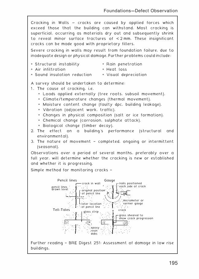
Cracking in Walls ~ cracks are caused by applied forces which
exceed those that the building can withstand. Most cracking is
superficial, occurring as materials dry out and subsequently shrink
to reveal minor surface fractures of < 2 mm. These insignificant
cracks can be made good with proprietary fillers.
Severe cracking in walls may result from foundation failure, due to
inadequate design or physical damage. Further problems could include:
A survey should be undertaken to determine:
1 . The cause of cracking, i.e.
* Loads applied externally (tree roots, subsoil movement).
* Climate/temperature changes (thermal movement).
* Moisture content change (faulty dpc, building leakage).
* Vibration (adjacent work, traffic).
* Changes in physical composition (salt or ice formation).
* Chemical change (corrosion, sulphate attack).
* Biological change (timber decay).
2. The effect on a building's performance (structural and
environmental).
3. The nature of movement † completed, ongoing or intermittent
(seasonal).
Observations over a period of several months, preferably over a
full year, will determine whether the cracking is new or established
and whether it is progressing.
Simple method for monitoring cracks †
pencil linesdrawn level
Pencil lines
Tell-Tales
Gaugecrack in wall
glass strip
original positionof pencil line
later locationof pencil line
epoxyresindabs
nails positionedeach side of crack
micrometer orvernier gauge
crack
glass sheared toshow crack progression
Further reading † BRE Digest 251: Assessment of damage in low rise
buildings.
* Structural instability
* Air infiltration
* Sound insulation reduction
* Rain penetration
* Heat loss
* Visual depreciation
195
Foundations---Defect Observation
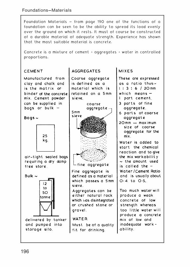
Foundation Materials ~ from page 190 one of the functions of a
foundation can be seen to be the ability to spread its load evenly
over the ground on which it rests. It must of course be constructed
of a durable material of adequate strength. Experience has shown
that the most suitable material is concrete.
Concrete is a mixture of cement + aggregates + water in controlled
proportions.
196
Foundations---Materials
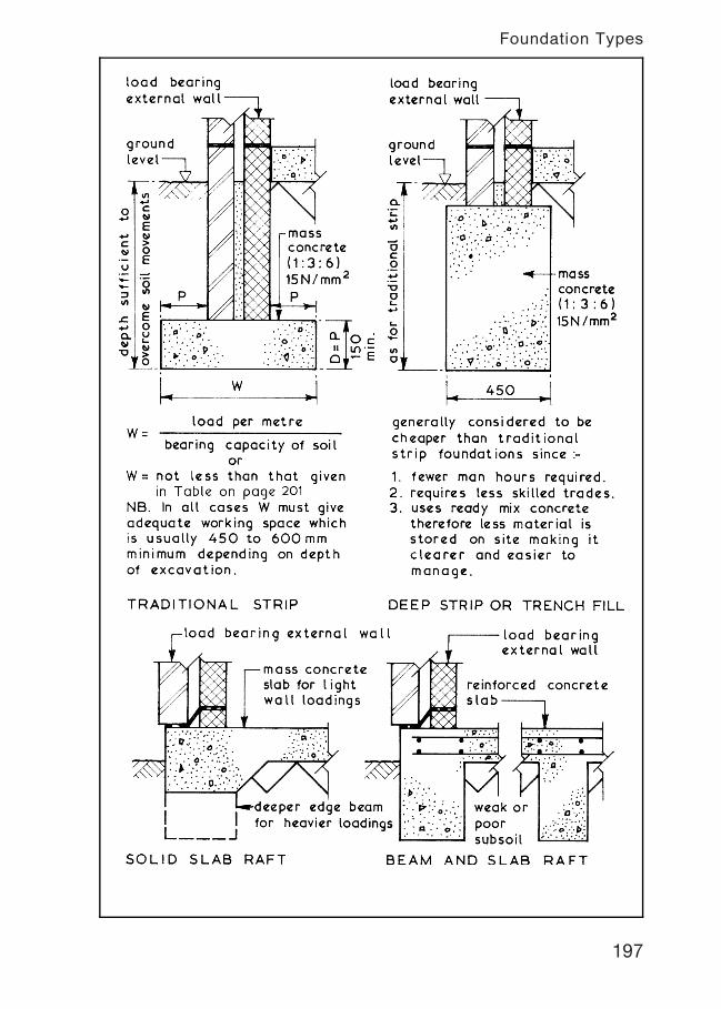
197
Foundation Types
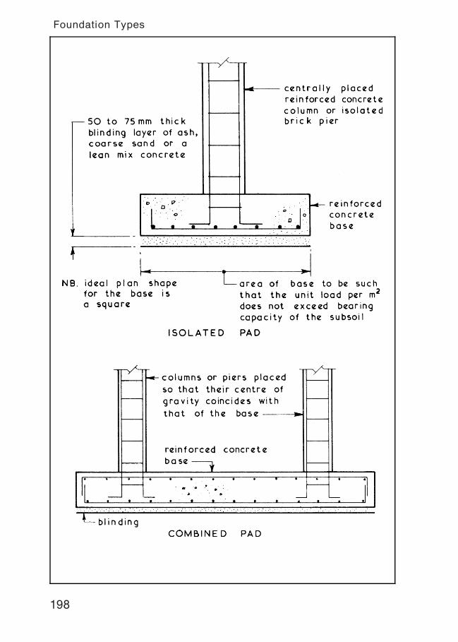
198
Foundation Types
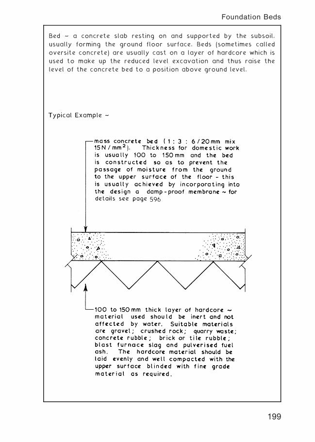
Bed ~ a concrete slab resting on and supported by the subsoil,
usually forming the ground floor surface. Beds (sometimes called
oversite concrete) are usually cast on a layer of hardcore which is
used to make up the reduced level excavation and thus raise the
level of the concrete bed to a position above ground level.
199
Foundation Beds
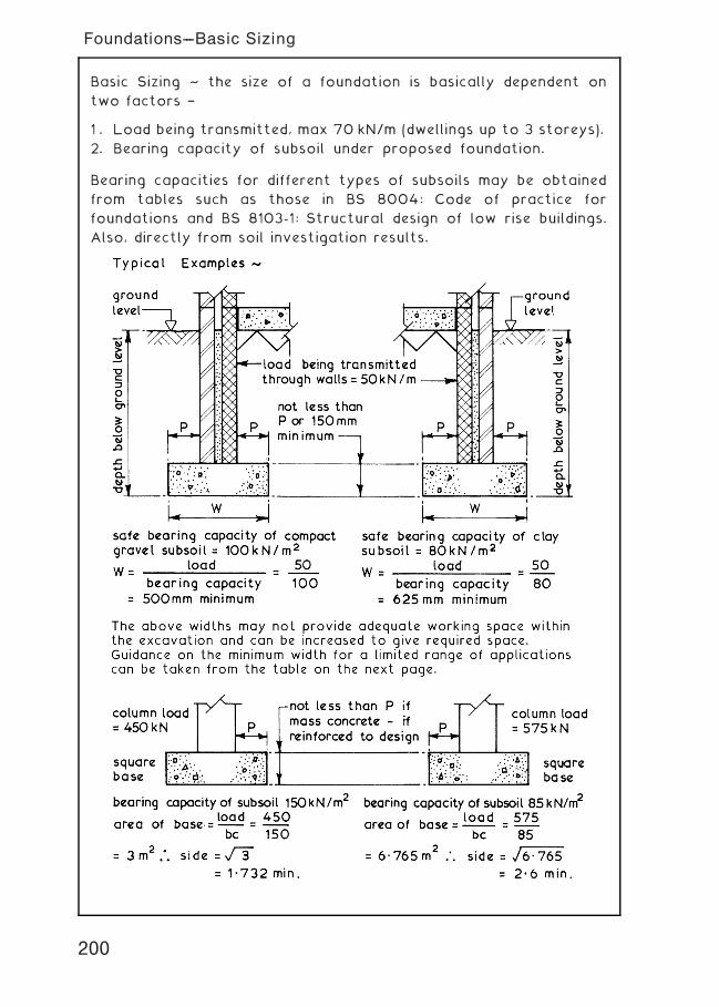
Basic Sizing ~ the size of a foundation is basically dependent on
two factors †
1 . Load being transmitted, max 70 kN/m (dwellings up to 3 storeys).
2. Bearing capacity of subsoil under proposed foundation.
Bearing capacities for different types of subsoils may be obtained
from tables such as those in BS 8004: Code of practice for
foundations and BS 8103-1: Structural design of low rise buildings.
Also, directly from soil investigation results.
200
Foundations---Basic Sizing
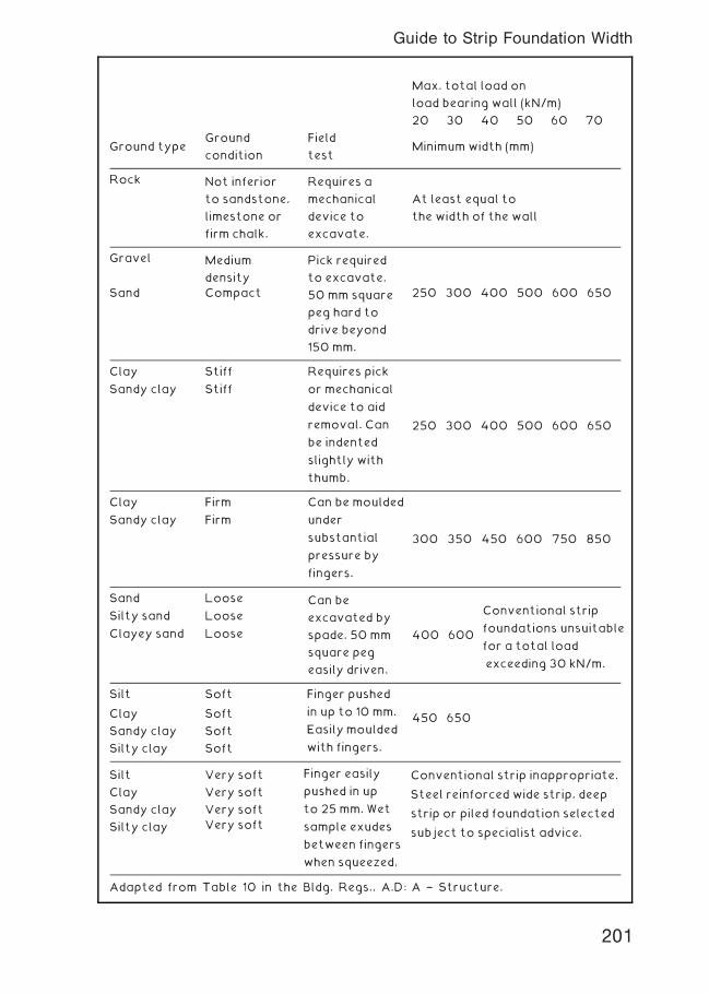
Max. total load on
load bearing wall (kN/m)
20 30 40 50 60 70
Ground typeGround
condition
Field
testMinimumwidth (mm)
Rock Not inferior
to sandstone,
limestone or
firm chalk.
Requires a
mechanical
device to
excavate.
At least equal to
the width of the wall
Gravel Medium
density
Pick required
to excavate.
Sand Compact 50 mm square
peg hard to
drive beyond
150 mm.
250 300 400 500 600 650
Clay
Sandy clay
Stiff
Stiff
Requires pick
or mechanical
device to aid
removal. Can
be indented
slightly with
thumb.
250 300 400 500 600 650
Clay
Sandy clay
Firm
Firm
Can be moulded
under
substantial
pressure by
fingers.
300 350 450 600 750 850
Sand
Silty sand
Clayey sand
Loose
Loose
Loose
Can be
excavated by
spade. 50 mm
square peg
easily driven.
400 600
Silt Soft
450 650Clay Soft
Sandy clay Soft
Silty clay Soft
Silt Very soft
Clay Very soft
Sandy clay Very soft
Silty clay Very soft
Adapted from Table 10 in the Bldg. Regs., A.D: A † Structure.
Conventional strip
foundations unsuitable
for a total load
exceeding 30 kN/m.
Finger pushed
in up to 10 mm.
Easilymoulded
with fingers.
Finger easily
pushed in up
to 25 mm. Wet
sample exudes
between fingers
when squeezed.
Conventional strip inappropriate.
Steel reinforced wide strip, deep
strip or piled foundation selected
subject to specialist advice.
201
Guide to Strip Foundation Width
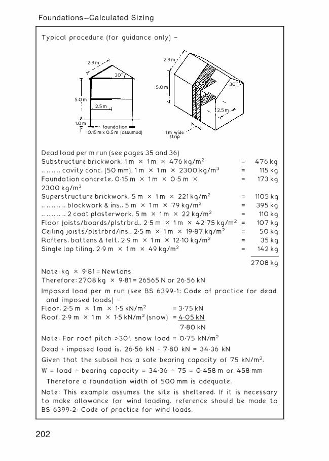
Typical procedure (for guidance only) †
5.0 m
5.0 m
1.0 m
2.5 m2.5 m
2.9 m2.9 m
30°
30°
1 m widestrip
foundation0.15 m x 0.5 m (assumed)
Note: For roof pitch >30�, snow load = 0„75 kN/m2
Dead + imposed load is, 26„56 kN + 7„80 kN = 34„36 kN
Given that the subsoil has a safe bearing capacity of 75 kN/m2,
W = load … bearing capacity = 34„36 … 75 = 0„458 m or 458 mm
Therefore a foundation width of 500 mm is adequate.
Note: This example assumes the site is sheltered. If it is necessary
to make allowance for wind loading, reference should be made to
BS 6399-2: Code of practice for wind loads.
Dead load per m run (see pages 35 and 36)
Substructure brickwork, 1 m � 1 m � 476 kg/m2 = 476 kg
.. .. .. .. cavity conc. (50 mm), 1 m � 1 m � 2300 kg/m3 = 115 kg
Foundation concrete, 0„15 m � 1 m � 0„5 m �2300 kg/m3
= 173 kg
Superstructure brickwork, 5 m � 1 m � 221 kg/m2 = 1105 kg
.. .. .. .. .. blockwork & ins., 5 m � 1 m � 79 kg/m2 = 395 kg
.. .. .. .. .. 2 coat plasterwork, 5 m � 1 m � 22 kg/m2 = 110 kg
Floor joists/boards/plstrbrd., 2„5 m � 1 m � 42„75 kg/m2 = 107 kg
Ceiling joists/plstrbrd/ins., 2„5 m � 1 m � 19„87 kg/m2 = 50 kg
Rafters, battens & felt, 2„9 m � 1 m � 12„10 kg/m2 = 35 kg
Single lap tiling, 2„9 m � 1 m � 49 kg/m2 = 142 kg
2708 kg
Note: kg � 9„81 = Newtons
Therefore: 2708 kg � 9„81 = 26565 N or 26„56 kN
Imposed load per m run (see BS 6399-1: Code of practice for dead
and imposed loads) †
Floor, 2„5 m � 1 m � 1„5 kN/m2 = 3„75 kN
Roof, 2„9 m � 1 m � 1„5 kN/m2 (snow) = 4„05 kN
7„80 kN
202
Foundations---Calculated Sizing
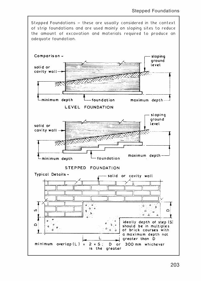
Stepped Foundations ~ these are usually considered in the context
of strip foundations and are used mainly on sloping sites to reduce
the amount of excavation and materials required to produce an
adequate foundation.
203
Stepped Foundations
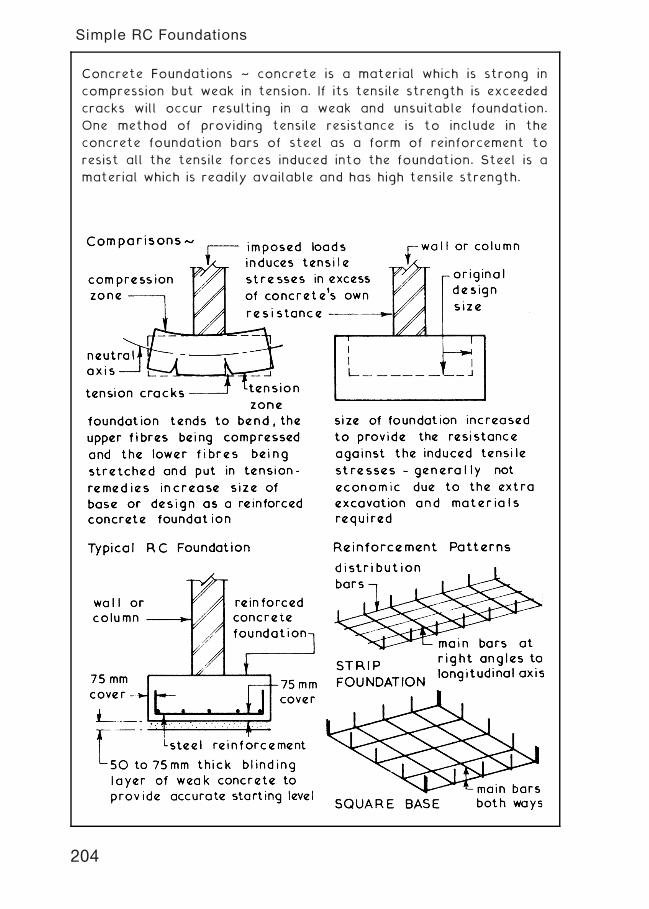
Concrete Foundations ~ concrete is a material which is strong in
compression but weak in tension. If its tensile strength is exceeded
cracks will occur resulting in a weak and unsuitable foundation.
One method of providing tensile resistance is to include in the
concrete foundation bars of steel as a form of reinforcement to
resist all the tensile forces induced into the foundation. Steel is a
material which is readily available and has high tensile strength.
204
Simple RC Foundations
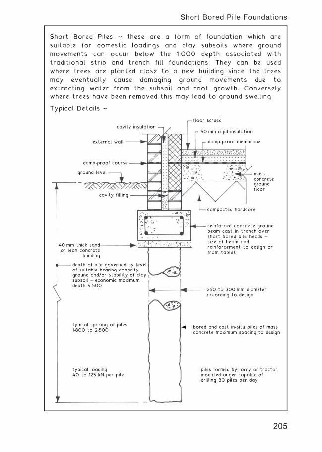
Short Bored Piles ~ these are a form of foundation which are
suitable for domestic loadings and clay subsoils where ground
movements can occur below the 1„000 depth associated with
traditional strip and trench fill foundations. They can be used
where trees are planted close to a new building since the trees
may eventually cause damaging ground movements due to
extracting water from the subsoil and root growth. Conversely
where trees have been removed this may lead to ground swelling.
Typical Details ~
40 mm thick sandor lean concrete
blinding
damp-proof course
damp-proof membrane
massconcretegroundfloor
compacted hardcore
reinforced concrete groundbeam cast in trench over short bored pile heads — size of beam and reinforcement to design orfrom tables
250 to 300 mm diameteraccording to design
bored and cast in-situ piles of massconcrete maximum spacing to design
piles formed by lorry or tractormounted auger capable ofdrilling 80 piles per day
ground level
cavity filling
external wall
cavity insulation50 mm rigid insulation
floor screed
depth of pile governed by levelof suitable bearing capacityground and/or stability of claysubsoil — economic maximumdepth 4.500
typical spacing of piles1.800 to 2.500
typical loading40 to 125 kN per pile
205
Short Bored Pile Foundations
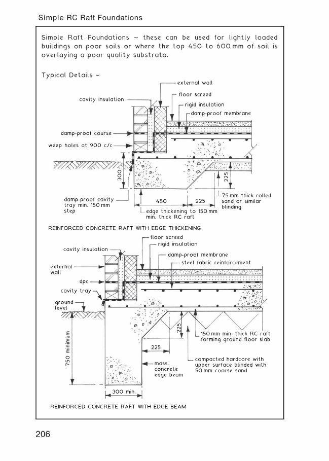
Simple Raft Foundations ~ these can be used for lightly loaded
buildings on poor soils or where the top 450 to 600 mm of soil is
overlaying a poor quality substrata.
Typical Details ~
cavity insulation
external wall
floor screed
rigid insulation
damp-proof membrane
damp-proof course
damp-proof cavitytray min. 150 mmstep
75 mm thick rolledsand or similarblinding
edge thickening to 150 mmmin. thick RC raft
300
225
450 225
weep holes at 900 c/c
REINFORCED CONCRETE RAFT WITH EDGE THICKENING
REINFORCED CONCRETE RAFT WITH EDGE BEAM
floor screed
rigid insulationcavity insulation
cavity tray
groundlevel
externalwall
dpc
damp-proof membrane
steel fabric reinforcement
150 mm min. thick RC raftforming ground floor slab
225
300 min.
750 m
inim
um
massconcreteedge beam
225
compacted hardcore withupper surface blinded with50 mm coarse sand
206
Simple RC Raft Foundations
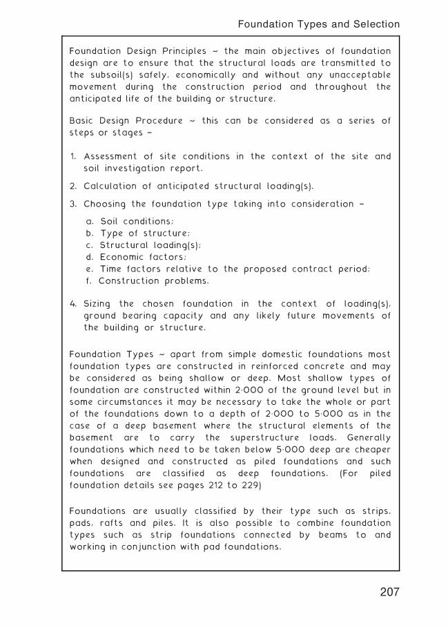
Foundation Design Principles ~ the main objectives of foundation
design are to ensure that the structural loads are transmitted to
the subsoil(s) safely, economically and without any unacceptable
movement during the construction period and throughout the
anticipated life of the building or structure.
Basic Design Procedure ~ this can be considered as a series of
steps or stages †
1. Assessment of site conditions in the context of the site and
soil investigation report.
2. Calculation of anticipated structural loading(s).
3. Choosing the foundation type taking into consideration †
a. Soil conditions;
b. Type of structure;
c. Structural loading(s);
d. Economic factors;
e. Time factors relative to the proposed contract period;
f. Construction problems.
4. Sizing the chosen foundation in the context of loading(s),
ground bearing capacity and any likely future movements of
the building or structure.
Foundation Types ~ apart from simple domestic foundations most
foundation types are constructed in reinforced concrete and may
be considered as being shallow or deep. Most shallow types of
foundation are constructed within 2„000 of the ground level but in
some circumstances it may be necessary to take the whole or part
of the foundations down to a depth of 2„000 to 5„000 as in the
case of a deep basement where the structural elements of the
basement are to carry the superstructure loads. Generally
foundations which need to be taken below 5„000 deep are cheaper
when designed and constructed as piled foundations and such
foundations are classified as deep foundations. (For piled
foundation details see pages 212 to 229)
Foundations are usually classified by their type such as strips,
pads, rafts and piles. It is also possible to combine foundation
types such as strip foundations connected by beams to and
working in conjunction with pad foundations.
207
Foundation Types and Selection
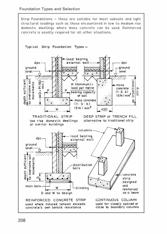
Strip Foundations ~ these are suitable for most subsoils and light
structural loadings such as those encountered in low to medium rise
domestic dwellings where mass concrete can be used. Reinforced
concrete is usually required for all other situations.
208
Foundation Types and Selection
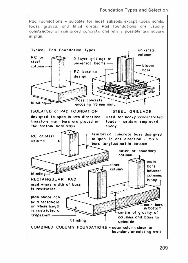
Pad Foundations ~ suitable for most subsoils except loose sands,
loose gravels and filled areas. Pad foundations are usually
constructed of reinforced concrete and where possible are square
in plan.
209
Foundation Types and Selection
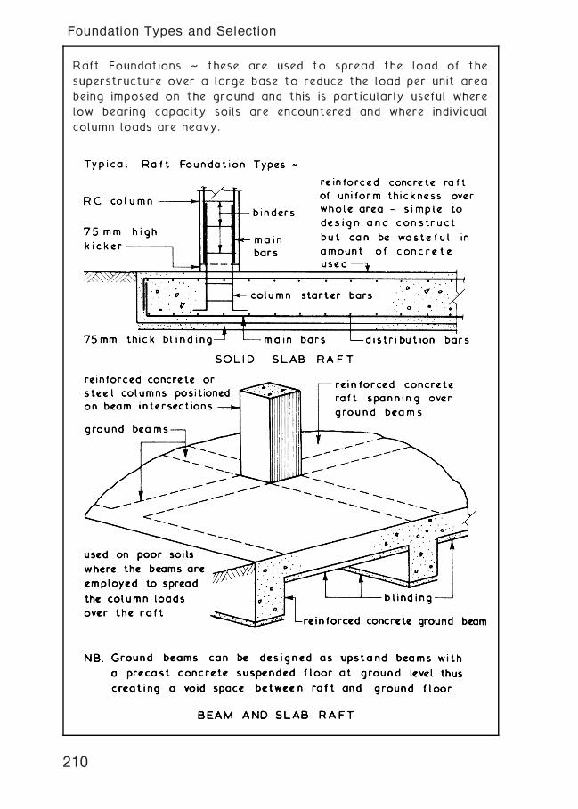
Raft Foundations ~ these are used to spread the load of the
superstructure over a large base to reduce the load per unit area
being imposed on the ground and this is particularly useful where
low bearing capacity soils are encountered and where individual
column loads are heavy.
210
Foundation Types and Selection
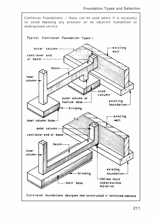
Cantilever Foundations ~ these can be used where it is necessary
to avoid imposing any pressure on an adjacent foundation or
underground service.
211
Foundation Types and Selection
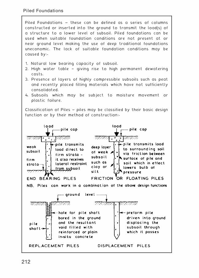
Piled Foundations ~ these can be defined as a series of columns
constructed or inserted into the ground to transmit the load(s) of
a structure to a lower level of subsoil. Piled foundations can be
used when suitable foundation conditions are not present at or
near ground level making the use of deep traditional foundations
uneconomic. The lack of suitable foundation conditions may be
caused by:-
1. Natural low bearing capacity of subsoil.
2. High water table † giving rise to high permanent dewatering
costs.
3. Presence of layers of highly compressible subsoils such as peat
and recently placed filling materials which have not sufficiently
consolidated.
4. Subsoils which may be subject to moisture movement or
plastic failure.
Classification of Piles ~ piles may be classified by their basic design
function or by their method of construction:-
212
Piled Foundations
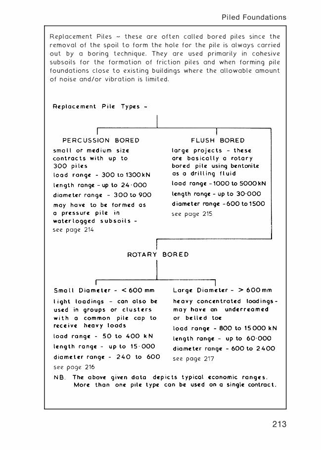
Replacement Piles ~ these are often called bored piles since the
removal of the spoil to form the hole for the pile is always carried
out by a boring technique. They are used primarily in cohesive
subsoils for the formation of friction piles and when forming pile
foundations close to existing buildings where the allowable amount
of noise and/or vibration is limited.
213
Piled Foundations
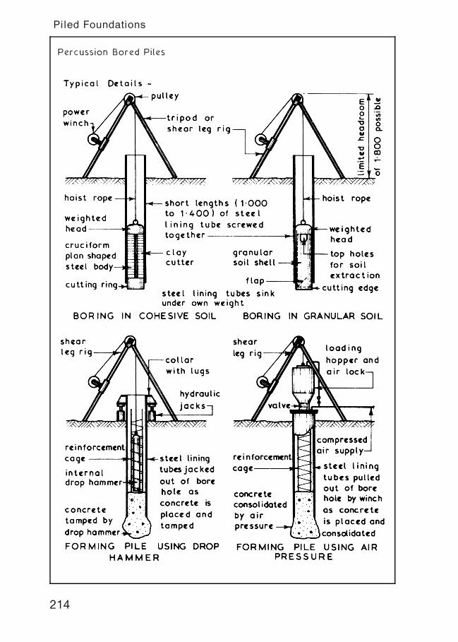
Percussion Bored Piles
214
Piled Foundations
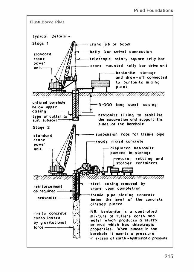
Flush Bored Piles
215
Piled Foundations
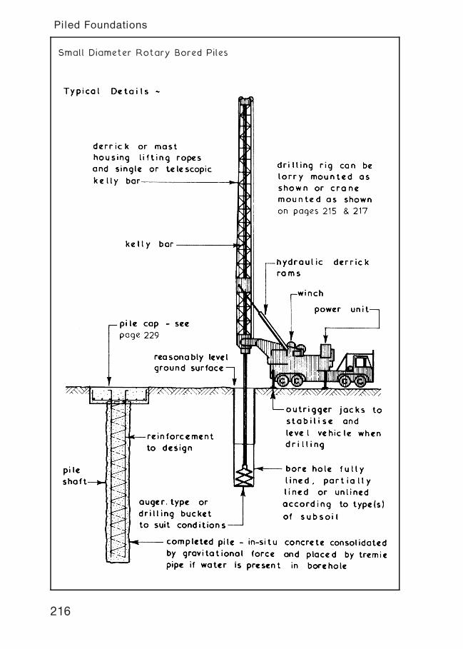
Small Diameter Rotary Bored Piles
216
Piled Foundations
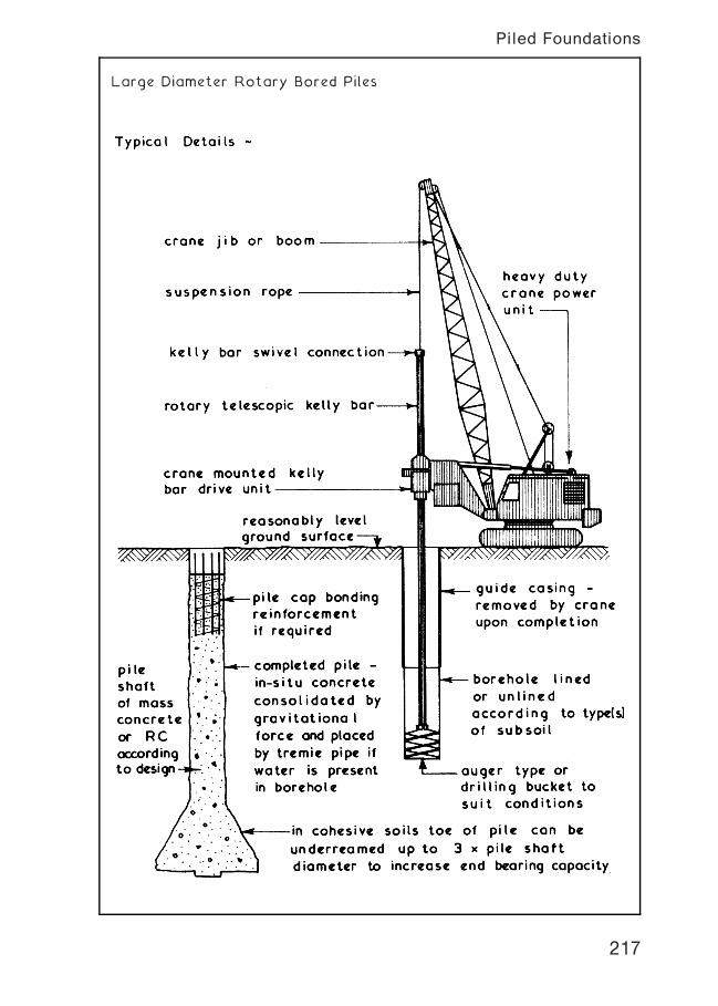
Large Diameter Rotary Bored Piles
217
Piled Foundations
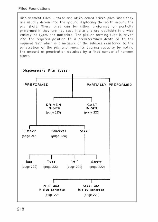
Displacement Piles ~ these are often called driven piles since they
are usually driven into the ground displacing the earth around the
pile shaft. These piles can be either preformed or partially
preformed if they are not cast in-situ and are available in a wide
variety of types and materials. The pile or forming tube is driven
into the required position to a predetermined depth or to the
required `set' which is a measure of the subsoils resistance to the
penetration of the pile and hence its bearing capacity by noting
the amount of penetration obtained by a fixed number of hammer
blows.
218
Piled Foundations
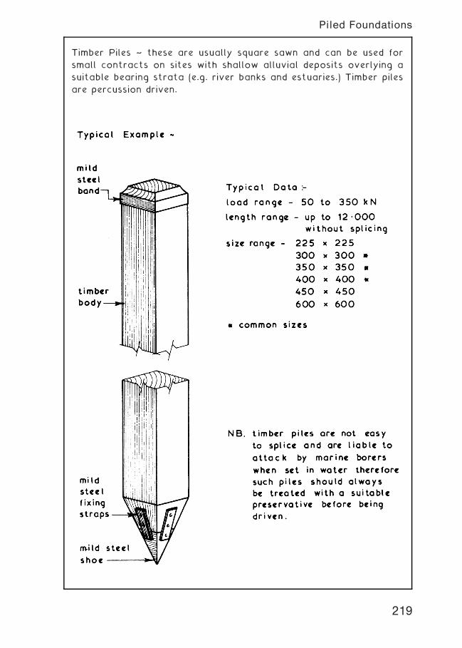
Timber Piles ~ these are usually square sawn and can be used for
small contracts on sites with shallow alluvial deposits overlying a
suitable bearing strata (e.g. river banks and estuaries.) Timber piles
are percussion driven.
219
Piled Foundations
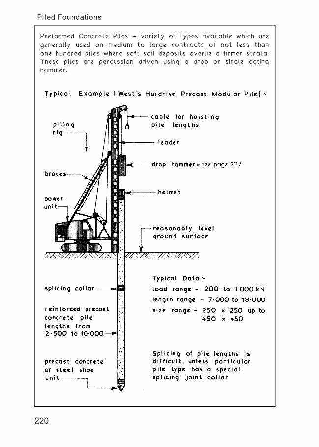
Preformed Concrete Piles ~ variety of types available which are
generally used on medium to large contracts of not less than
one hundred piles where soft soil deposits overlie a firmer strata.
These piles are percussion driven using a drop or single acting
hammer.
220
Piled Foundations
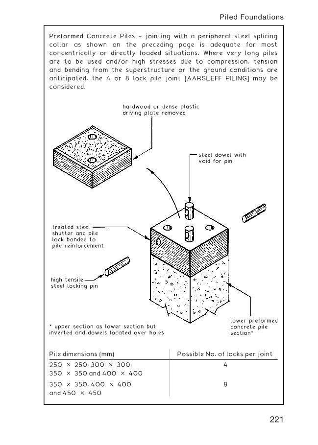
Preformed Concrete Piles † jointing with a peripheral steel splicing
collar as shown on the preceding page is adequate for most
concentrically or directly loaded situations. Where very long piles
are to be used and/or high stresses due to compression, tension
and bending from the superstructure or the ground conditions are
anticipated, the 4 or 8 lock pile joint [AARSLEFF PILING] may be
considered.
hardwood or dense plasticdriving plate removed
steel dowel withvoid for pin
treated steelshutter and pilelock bonded topile reinforcement
* upper section as lower section butinverted and dowels located over holes
lower preformedconcrete pilesection*
high tensilesteel locking pin
Pile dimensions (mm) Possible No. of locks per joint
250 � 250, 300 � 300,
350 � 350 and 400 � 400
4
350 � 350, 400 � 400
and 450 � 450
8
221
Piled Foundations
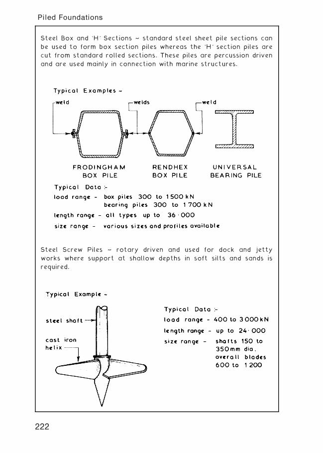
Steel Box and `H' Sections ~ standard steel sheet pile sections can
be used to form box section piles whereas the `H' section piles are
cut from standard rolled sections. These piles are percussion driven
and are used mainly in connection with marine structures.
Steel Screw Piles ~ rotary driven and used for dock and jetty
works where support at shallow depths in soft silts and sands is
required.
222
Piled Foundations
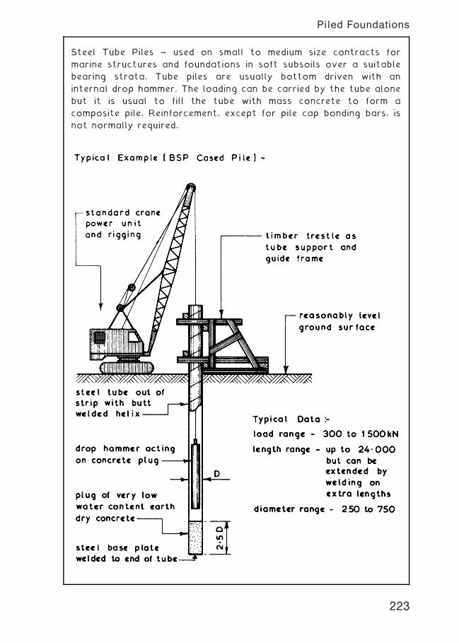
Steel Tube Piles ~ used on small to medium size contracts for
marine structures and foundations in soft subsoils over a suitable
bearing strata. Tube piles are usually bottom driven with an
internal drop hammer. The loading can be carried by the tube alone
but it is usual to fill the tube with mass concrete to form a
composite pile. Reinforcement, except for pile cap bonding bars, is
not normally required.
223
Piled Foundations
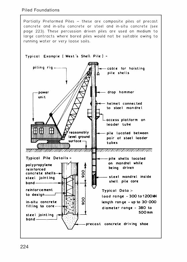
Partially Preformed Piles ~ these are composite piles of precast
concrete and in-situ concrete or steel and in-situ concrete (see
page 223). These percussion driven piles are used on medium to
large contracts where bored piles would not be suitable owing to
running water or very loose soils.
224
Piled Foundations
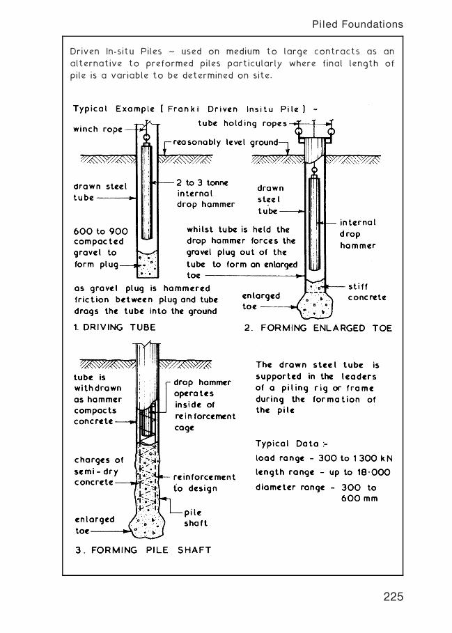
Driven In-situ Piles ~ used on medium to large contracts as an
alternative to preformed piles particularly where final length of
pile is a variable to be determined on site.
225
Piled Foundations
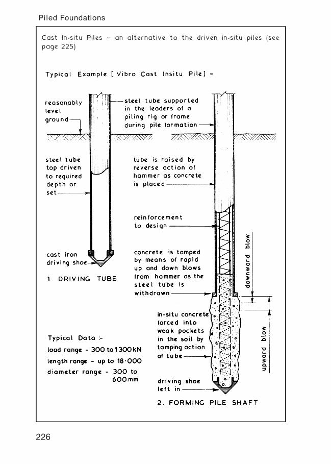
Cast In-situ Piles ~ an alternative to the driven in-situ piles (see
page 225)
226
Piled Foundations
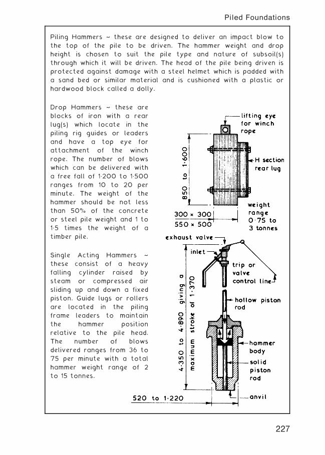
Piling Hammers ~ these are designed to deliver an impact blow to
the top of the pile to be driven. The hammer weight and drop
height is chosen to suit the pile type and nature of subsoil(s)
through which it will be driven. The head of the pile being driven is
protected against damage with a steel helmet which is padded with
a sand bed or similar material and is cushioned with a plastic or
hardwood block called a dolly.
Drop Hammers ~ these are
blocks of iron with a rear
lug(s) which locate in the
piling rig guides or leaders
and have a top eye for
attachment of the winch
rope. The number of blows
which can be delivered with
a free fall of 1„200 to 1„500
ranges from 10 to 20 per
minute. The weight of the
hammer should be not less
than 50% of the concrete
or steel pile weight and 1 to
1„5 times the weight of a
timber pile.
Single Acting Hammers ~
these consist of a heavy
falling cylinder raised by
steam or compressed air
sliding up and down a fixed
piston. Guide lugs or rollers
are located in the piling
frame leaders to maintain
the hammer position
relative to the pile head.
The number of blows
delivered ranges from 36 to
75 per minute with a total
hammer weight range of 2
to 15 tonnes.
227
Piled Foundations
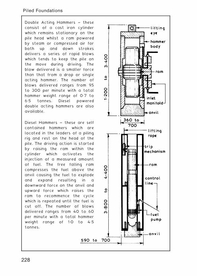
Double Acting Hammers ~ these
consist of a cast iron cylinder
which remains stationary on the
pile head whilst a ram powered
by steam or compressed air for
both up and down strokes
delivers a series of rapid blows
which tends to keep the pile on
the move during driving. The
blow delivered is a smaller force
than that from a drop or single
acting hammer. The number of
blows delivered ranges from 95
to 300 per minute with a total
hammer weight range of 0„7 to
6„5 tonnes. Diesel powered
double acting hammers are also
available.
Diesel Hammers ~ these are self
contained hammers which are
located in the leaders of a piling
rig and rest on the head of the
pile. The driving action is started
by raising the ram within the
cylinder which activates the
injection of a measured amount
of fuel. The free falling ram
compresses the fuel above the
anvil causing the fuel to explode
and expand resulting in a
downward force on the anvil and
upward force which raises the
ram to recommence the cycle
which is repeated until the fuel is
cut off. The number of blows
delivered ranges from 40 to 60
per minute with a total hammer
weight range of 1„0 to 4„5
tonnes.
228
Piled Foundations
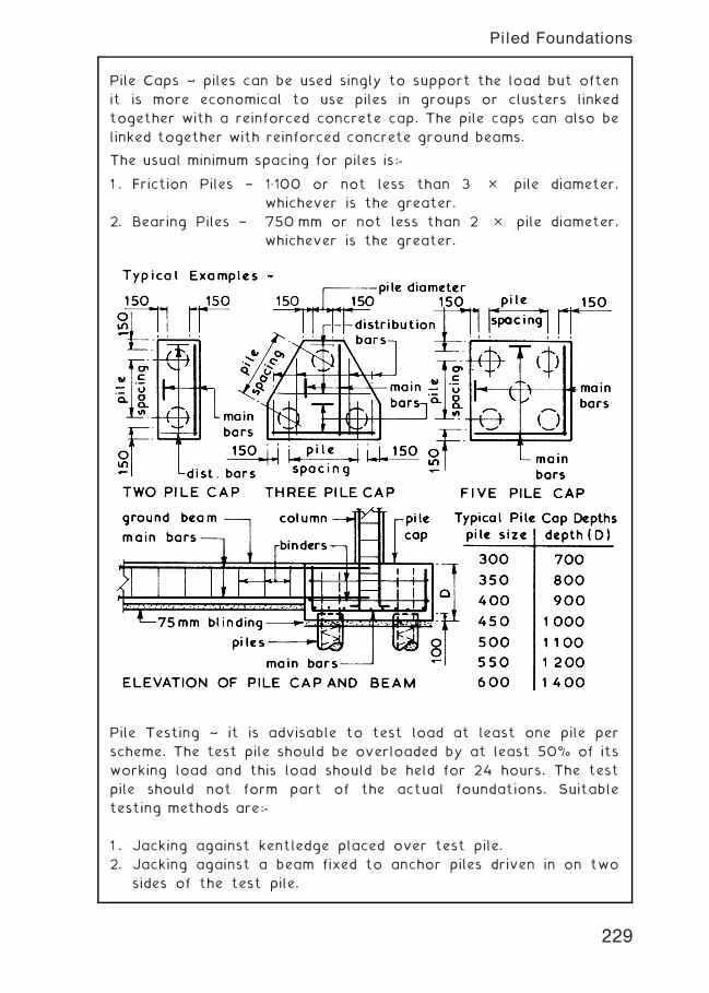
Pile Caps ~ piles can be used singly to support the load but often
it is more economical to use piles in groups or clusters linked
together with a reinforced concrete cap. The pile caps can also be
linked together with reinforced concrete ground beams.
The usual minimum spacing for piles is:-
1 . Friction Piles † 1„100 or not less than 3 � pile diameter,
whichever is the greater.
2. Bearing Piles † 750 mm or not less than 2 � pile diameter,
whichever is the greater.
Pile Testing ~ it is advisable to test load at least one pile per
scheme. The test pile should be overloaded by at least 50% of its
working load and this load should be held for 24 hours. The test
pile should not form part of the actual foundations. Suitable
testing methods are:-
1 . Jacking against kentledge placed over test pile.
2. Jacking against a beam fixed to anchor piles driven in on two
sides of the test pile.
229
Piled Foundations
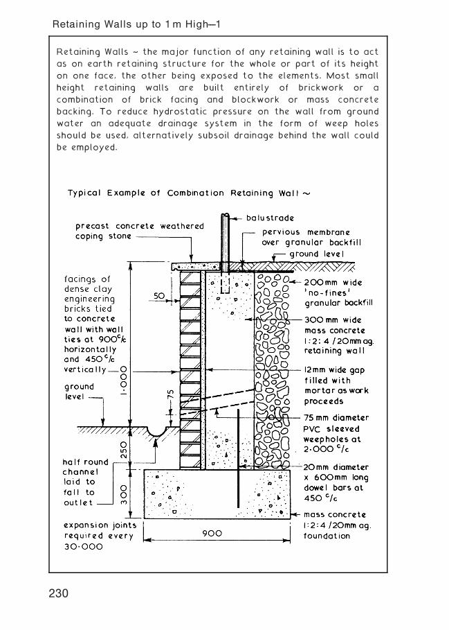
Retaining Walls ~ the major function of any retaining wall is to act
as on earth retaining structure for the whole or part of its height
on one face, the other being exposed to the elements. Most small
height retaining walls are built entirely of brickwork or a
combination of brick facing and blockwork or mass concrete
backing. To reduce hydrostatic pressure on the wall from ground
water an adequate drainage system in the form of weep holes
should be used, alternatively subsoil drainage behind the wall could
be employed.
230
Retaining Walls up to 1m High---1
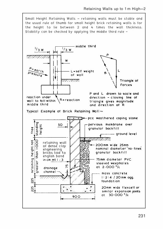
Small Height Retaining Walls ~ retaining walls must be stable and
the usual rule of thumb for small height brick retaining walls is for
the height to lie between 2 and 4 times the wall thickness.
Stability can be checked by applying the middle third rule †
231
Retaining Walls up to 1m High---2
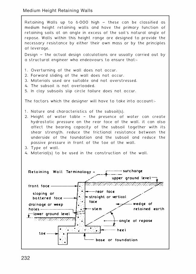
Retaining Walls up to 6„000 high ~ these can be classified as
medium height retaining walls and have the primary function of
retaining soils at an angle in excess of the soil's natural angle of
repose. Walls within this height range are designed to provide the
necessary resistance by either their own mass or by the principles
of leverage.
Design ~ the actual design calculations are usually carried out by
a structural engineer who endeavours to ensure that:-
1 . Overturning of the wall does not occur.
2. Forward sliding of the wall does not occur.
3. Materials used are suitable and not overstressed.
4. The subsoil is not overloaded.
5. In clay subsoils slip circle failure does not occur.
The factors which the designer will have to take into account:-
1 . Nature and characteristics of the subsoil(s).
2. Height of water table † the presence of water can create
hydrostatic pressure on the rear face of the wall, it can also
affect the bearing capacity of the subsoil together with its
shear strength, reduce the frictional resistance between the
underside of the foundation and the subsoil and reduce the
passive pressure in front of the toe of the wall.
3. Type of wall.
4. Material(s) to be used in the construction of the wall.
232
Medium Height Retaining Walls
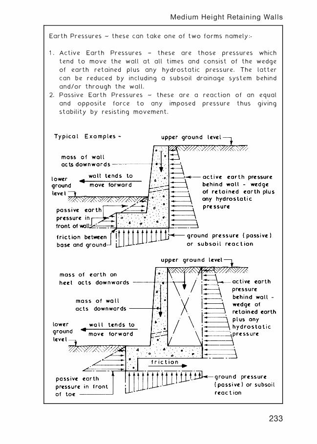
Earth Pressures ~ these can take one of two forms namely:-
1 . Active Earth Pressures † these are those pressures which
tend to move the wall at all times and consist of the wedge
of earth retained plus any hydrostatic pressure. The latter
can be reduced by including a subsoil drainage system behind
and/or through the wall.
2. Passive Earth Pressures ~ these are a reaction of an equal
and opposite force to any imposed pressure thus giving
stability by resisting movement.
233
Medium Height Retaining Walls
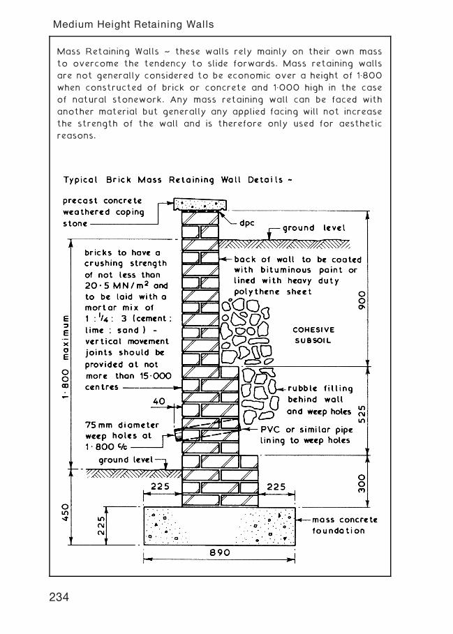
Mass Retaining Walls ~ these walls rely mainly on their own mass
to overcome the tendency to slide forwards. Mass retaining walls
are not generally considered to be economic over a height of 1„800
when constructed of brick or concrete and 1„000 high in the case
of natural stonework. Any mass retaining wall can be faced with
another material but generally any applied facing will not increase
the strength of the wall and is therefore only used for aesthetic
reasons.
234
Medium Height Retaining Walls
235
Medium Height Retaining Walls
Cantilever Retaining Walls ~ these are constructed of reinforced
concrete with an economic height range of 1„200 to 6„000. They
work on the principles of leverage where the stem is designed as a
cantilever fixed at the base and base is designed as a cantilever
fixed at the stem. Several formats are possible and in most cases
a beam is placed below the base to increase the total passive
resistance to sliding. Facing materials can be used in a similar
manner to that shown on page 235.
236
Medium Height Retaining Walls
Formwork ~ concrete retaining walls can be cast in one of three
ways † full height; climbing (page 238) or against earth face (page
239).
Full Height Casting ~ this can be carried out if the wall is to be
cast as a freestanding wall and allowed to cure and gain strength
before the earth to be retained is backfilled behind the wall.
Considerations are the height of the wall, anticipated pressure of
wet concrete, any strutting requirements and the availability of
suitable materials to fabricate the formwork. As with all types
of formwork a traditional timber format or a patent system using
steel forms could be used.
237
Medium Height Retaining Walls
Climbing Formwork or Lift Casting ~ this method can be employed
on long walls, high walls or where the amount of concrete which
can be placed in a shift is limited.
238
Medium Height Retaining Walls
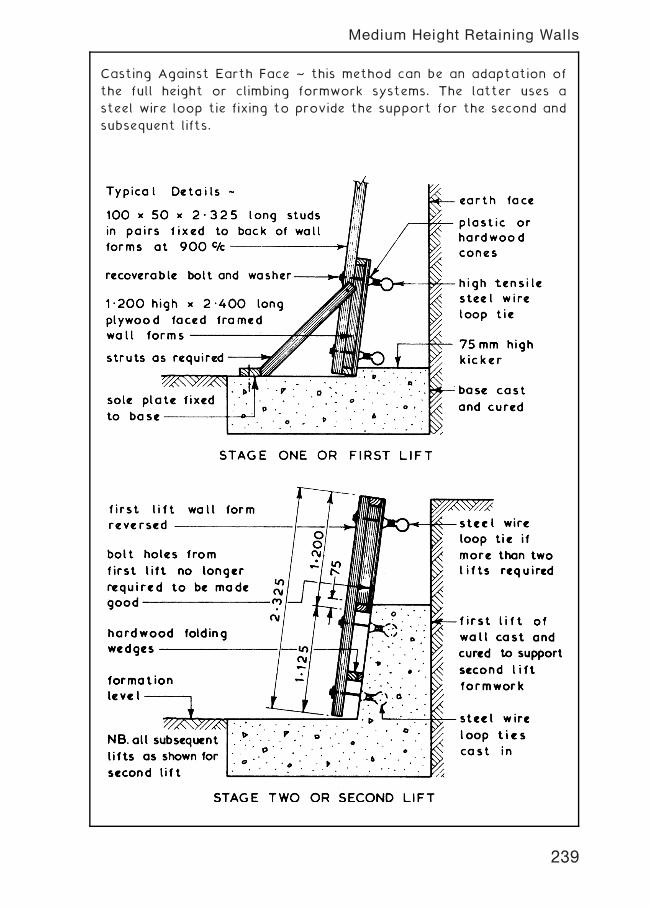
Casting Against Earth Face ~ this method can be an adaptation of
the full height or climbing formwork systems. The latter uses a
steel wire loop tie fixing to provide the support for the second and
subsequent lifts.
239
Medium Height Retaining Walls
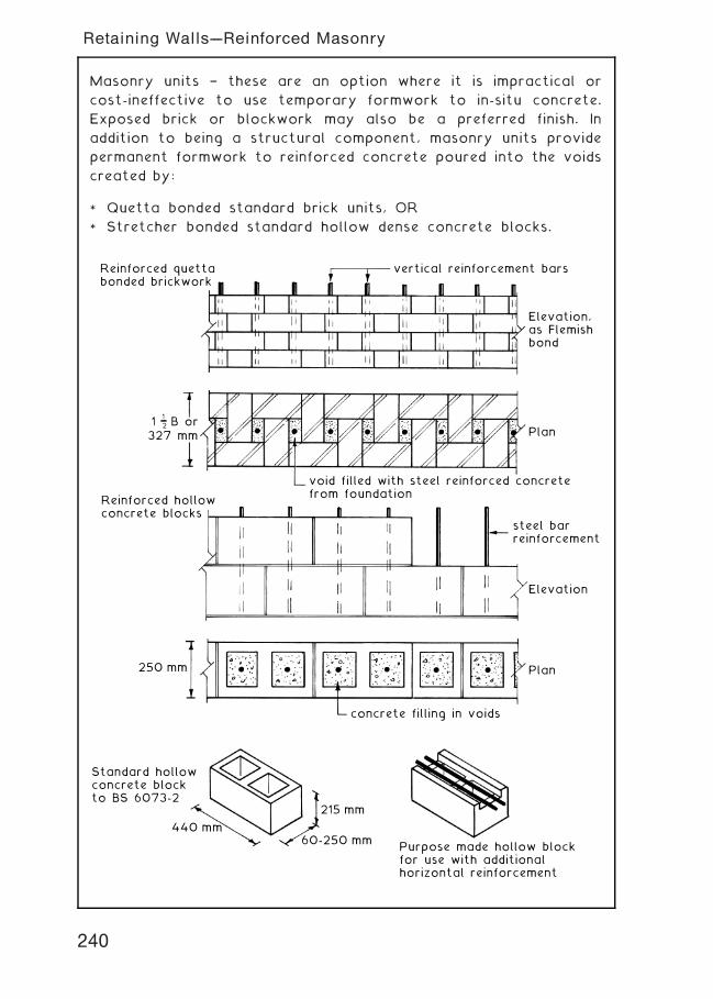
Masonry units † these are an option where it is impractical or
cost-ineffective to use temporary formwork to in-situ concrete.
Exposed brick or blockwork may also be a preferred finish. In
addition to being a structural component, masonry units provide
permanent formwork to reinforced concrete poured into the voids
created by:
* Quetta bonded standard brick units, OR
* Stretcher bonded standard hollow dense concrete blocks.
vertical reinforcement bars
void filled with steel reinforced concretefrom foundation
concrete filling in voids
Elevation,as Flemishbond
Elevation
steel barreinforcement
Plan
Plan250 mm
327 mm1 B or1
2
Reinforced quettabonded brickwork
Reinforced hollowconcrete blocks
Standard hollowconcrete blockto BS 6073-2
Purpose made hollow blockfor use with additionalhorizontal reinforcement
440 mm60-250 mm
215 mm
240
Retaining Walls---Reinforced Masonry
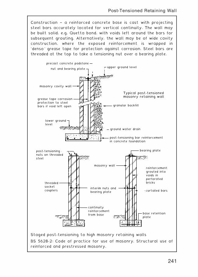
Construction † a reinforced concrete base is cast with projecting
steel bars accurately located for vertical continuity. The wall may
be built solid, e.g. Quetta bond, with voids left around the bars for
subsequent grouting. Alternatively, the wall may be of wide cavity
construction, where the exposed reinforcement is wrapped in
`denso' grease tape for protection against corrosion. Steel bars are
threaded at the top to take a tensioning nut over a bearing plate.
Typical post-tensionedmasonry retaining wall
precast concrete padstone
nut and bearing plateupper ground level
granular backfill
ground water drain
post-tensioning bar reinforcementin concrete foundation
masonry cavity wall
grease tape corrosionprotection to steelbars if void left open
lower groundlevel
post-tensioningnuts on threadedsteel
threadedsocketcouplers
masonry wall
bearing plate
reinforcementgrouted intovoids inperforatedbricks
curtailed bars
base retentionplate
interim nuts andbearing plate
continuityreinforcementfrom base
Staged post-tensioning to high masonry retaining walls
BS 5628-2: Code of practice for use of masonry. Structural use of
reinforced and prestressed masonry.
241
Post-Tensioned Retaining Wall
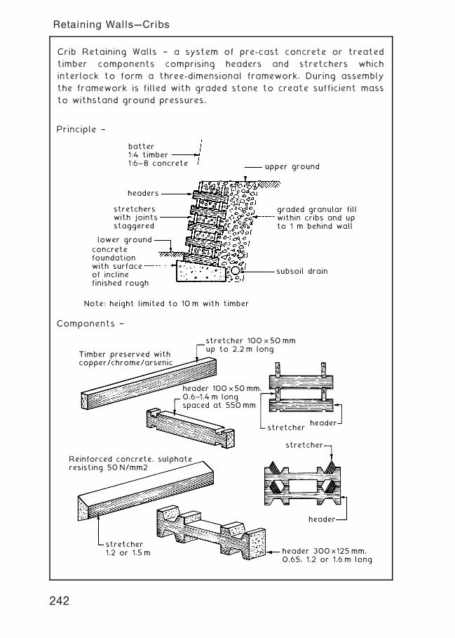
Crib Retaining Walls † a system of pre-cast concrete or treated
timber components comprising headers and stretchers which
interlock to form a three-dimensional framework. During assembly
the framework is filled with graded stone to create sufficient mass
to withstand ground pressures.
batter1:4 timber1:6– 8 concrete
headers
stretcherswith jointsstaggered
concretefoundationwith surfaceof inclinefinished rough
Note: height limited to 10 m with timber
upper ground
graded granular fillwithin cribs and upto 1 m behind wall
subsoil drain
lower ground
stretcher 100 × 50 mmup to 2.2 m long
header 100 × 50 mm,0.6–1.4 m longspaced at 550 mm
stretcher1.2 or 1.5 m
Timber preserved withcopper/chrome/arsenic
Reinforced concrete, sulphateresisting 50 N/mm2
header
header 300 × 125 mm,0.65, 1.2 or 1.6 m long
headerstretcher
stretcher
Principle †
Components †
242
Retaining Walls---Cribs
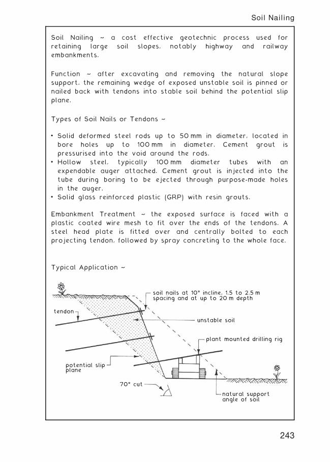
Soil Nailing ~ a cost effective geotechnic process used for
retaining large soil slopes, notably highway and railway
embankments.
Function ~ after excavating and removing the natural slope
support, the remaining wedge of exposed unstable soil is pinned or
nailed back with tendons into stable soil behind the potential slip
plane.
Types of Soil Nails or Tendons ~
• Solid deformed steel rods up to 50 mm in diameter, located in
bore holes up to 100 mm in diameter. Cement grout is
pressurised into the void around the rods.
• Hollow steel, typically 100 mm diameter tubes with an
expendable auger attached. Cement grout is injected into the
tube during boring to be ejected through purpose-made holes
in the auger.
• Solid glass reinforced plastic (GRP) with resin grouts.
Embankment Treatment ~ the exposed surface is faced with a
plastic coated wire mesh to fit over the ends of the tendons. A
steel head plate is fitted over and centrally bolted to each
projecting tendon, followed by spray concreting to the whole face.
Typical Application ~
soil nails at 10ƒ incline, 1.5 to 2.5 mspacing and at up to 20 m depth
unstable soil
plant mounted drilling rig
natural support angle of soil
70ƒ cut
potential slipplane
tendon
243
Soil Nailing
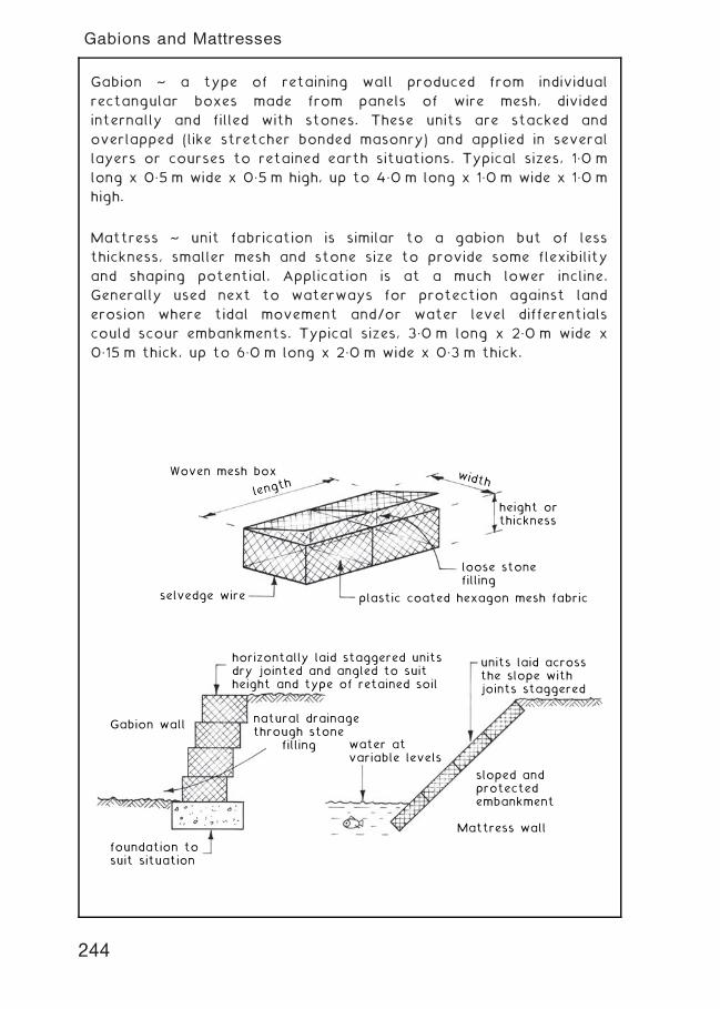
Gabion ~ a type of retaining wall produced from individual
rectangular boxes made from panels of wire mesh, divided
internally and filled with stones. These units are stacked and
overlapped (like stretcher bonded masonry) and applied in several
layers or courses to retained earth situations. Typical sizes, 1„0 m
long x 0„5 m wide x 0„5 m high, up to 4„0 m long x 1„0 m wide x 1„0 m
high.
Mattress ~ unit fabrication is similar to a gabion but of less
thickness, smaller mesh and stone size to provide some flexibility
and shaping potential. Application is at a much lower incline.
Generally used next to waterways for protection against land
erosion where tidal movement and/or water level differentials
could scour embankments. Typical sizes, 3„0 m long x 2„0 m wide x
0„15 m thick, up to 6„0 m long x 2„0 m wide x 0„3 m thick.
Gabion wall
foundation tosuit situation
horizontally laid staggered unitsdry jointed and angled to suit height and type of retained soil
units laid acrossthe slope withjoints staggered
sloped andprotectedembankment
Mattress wall
natural drainagethrough stone filling water at
variable levels
length
Woven mesh box
selvedge wire plastic coated hexagon mesh fabric
loose stonefilling
height orthickness
width
244
Gabions and Mattresses
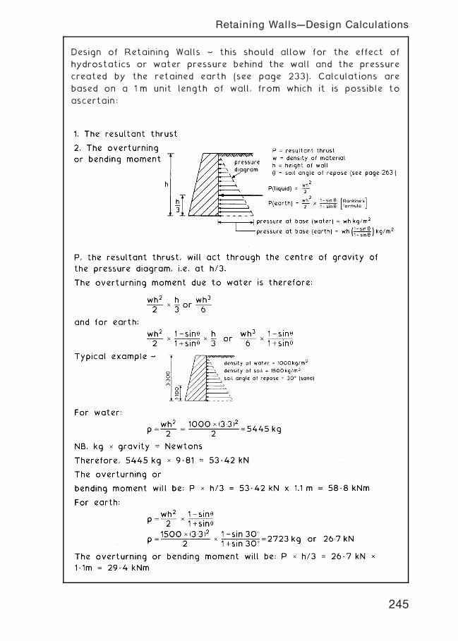
Design of Retaining Walls ~ this should allow for the effect of
hydrostatics or water pressure behind the wall and the pressure
created by the retained earth (see page 233). Calculations are
based on a 1 m unit length of wall, from which it is possible to
ascertain:
245
Retaining Walls---Design Calculations
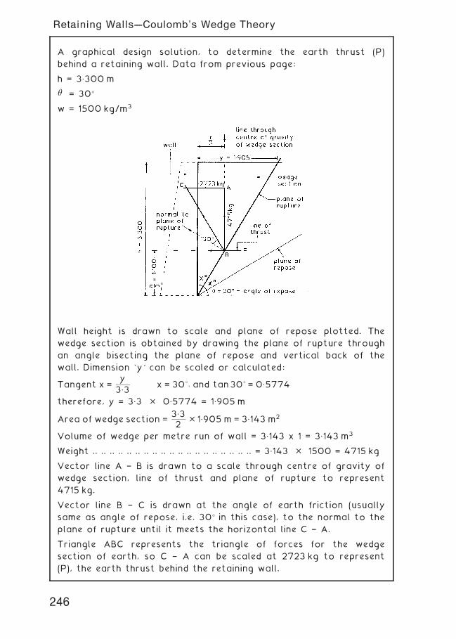
A graphical design solution, to determine the earth thrust (P)
behind a retaining wall. Data from previous page:
h = 3„300 m
� = 30�
w = 1500 kg/m3
Wall height is drawn to scale and plane of repose plotted. The
wedge section is obtained by drawing the plane of rupture through
an angle bisecting the plane of repose and vertical back of the
wall. Dimension `y' can be scaled or calculated:
Tangent x =y
3„3x = 30�; and tan30� = 0„5774
therefore, y = 3„3 � 0„5774 = 1„905 m
Area of wedge section =3„32 � 1„905 m = 3„143 m2
Volume of wedge per metre run of wall = 3„143 x 1 = 3„143 m3
Weight .. .. .. .. .. .. .. .. .. .. .. .. .. .. .. .. .. .. .. = 3„143 � 1500 = 4715 kg
Vector line A † B is drawn to a scale through centre of gravity of
wedge section, line of thrust and plane of rupture to represent
4715 kg.
Vector line B † C is drawn at the angle of earth friction (usually
same as angle of repose, i.e. 30� in this case), to the normal to the
plane of rupture until it meets the horizontal line C † A.
Triangle ABC represents the triangle of forces for the wedge
section of earth, so C † A can be scaled at 2723 kg to represent
(P), the earth thrust behind the retaining wall.
246
Retaining Walls---Coulomb’s Wedge Theory
Open Excavations ~ one of the main problems which can be
encountered with basement excavations is the need to provide
temporary support or timbering to the sides of the excavation.
This can be intrusive when the actual construction of the basement
floor and walls is being carried out. One method is to use battered
excavation sides cut back to a safe angle of repose thus
eliminating the need for temporary support works to the sides of
the excavation.
In economic terms the costs of plant and manpower to cover the
extra excavation, backfilling and consolidating must be offset by
the savings made by omitting the temporary support works to the
sides of the excavation. The main disadvantage of this method is
the large amount of free site space required.
247
Basement Excavations
Perimeter Trench Excavations ~ in this method a trench wide
enough for the basement walls to be constructed is excavated and
supported with timbering as required. It may be necessary for
runners or steel sheet piling to be driven ahead of the excavation
work. This method can be used where weak subsoils are
encountered so that the basement walls act as permanent
timbering whilst the mound or dumpling is excavated and the base
slab cast. Perimeter trench excavations can also be employed in
firm subsoils when the mechanical plant required for excavating the
dumpling is not available at the right time.
248
Basement Excavations
Complete Excavation ~ this method can be used in firm subsoils
where the centre of the proposed basement can be excavated first
to enable the basement slab to be cast thus giving protection to
the subsoil at formation level. The sides of excavation to the
perimeter of the basement can be supported from the formation
level using raking struts or by using raking struts pitched from the
edge of the basement slab.
249
Basement Excavations
Excavating Plant ~ the choice of actual pieces of plant to be used
in any construction activity is a complex matter taking into
account many factors. Specific details of various types of
excavators are given on pages 159 to 163. At this stage it is only
necessary to consider basic types for particular operations. In the
context of basement excavation two forms of excavator could be
considered.
250
Basement Excavations
Basement Construction ~ in the general context of buildings a
basement can be defined as a storey which is below the ground
storey and is therefore constructed below ground level. Most
basements can be classified into one of three groups:-
251
Basement Construction
Deep Basement Construction ~ basements can be constructed
within a cofferdam or other temporary supported excavation (see
Basement Excavations on pages 247 to 249) up to the point when
these methods become uneconomic, unacceptable or both due to
the amount of necessary temporary support work. Deep basements
can be constructed by installing diaphragm walls within a trench
and providing permanent support with ground anchors or by using
the permanent lateral support given by the internal floor during
the excavation period (see next page). Temporary lateral support
during the excavation period can be provided by lattice beams
spanning between the diaphragm walls (see next page).
NB. vertical ground anchors installed through the lowest floor can
be used to overcome any tendency to flotation during the
construction period
252
Basement Construction
253
Basement Construction
Waterproofing Basements ~ basements can be waterproofed by one
of three basic methods namely:-
1 . Use of dense monolithic concrete walls and floor
2. Tanking techniques (see pages 256 & 257)
3. Drained cavity system (see page 258)
Dense Monolithic Concrete † the main objective is to form a watertight
basement using dense high quality reinforced or prestressed concrete by
a combination of good materials, good workmanship, attention to
design detail and on site construction methods. If strict control of all
aspects is employed a soundwatertight structure can beproduced but it
should be noted that such structures are not always water
vapourproof. If the latter is desirable somewaterproof coating, lining or
tanking should be used. The watertightness of dense concrete mixes
depends primarily upon two factors:-
1 . Water/cement ratio.
2. Degree of compaction.
The hydration of cement during the hardening process produces heat
therefore to prevent early stage cracking the temperature changes
within the hardening concrete should be kept to a minimum. The greater
the cement content the more is the evolution of heat therefore the mix
should contain no more cement than is necessary to fulfil design
requirements. Concrete with a free water/cement ratio of 0.5 is
watertight and although the permeability is three time more at a ratio
of 0.6 it is for practical purposes still watertight but above this ratio
the concrete becomes progressively less watertight. For lower water/
cement ratios the workability of the mix would have to be increased,
usually by adding more cement, to enable the concrete to be fully
compacted.
Admixtures † if the ingredients of good design, materials and
workmanship are present watertight concrete can be produced
without the use of admixtures. If admixtures are used they should
be carefully chosen and used to obtain a specific objective:-
1 . Water-reducing admixtures † used to improve workability
2. Retarding admixtures † slow down rate of hardening
3. Accelerating admixtures † increase rate of hardening † useful for
low temperatures † calcium chloride not suitable for reinforced
concrete.
4. Water-repelling admixtures † effective only with low water
head, will not improve poor quality or porous mixes.
5. Air-entraining admixtures † increases workability † lowers water
content.
254
Waterproofing Basements
Joints ~ in general these are formed in basement constructions to
provide for movement accommodation (expansion joints) or to
create a convenient stopping point in the construction process
(construction joints). Joints are lines of weakness which will leak
unless carefully designed and constructed therefore they should be
simple in concept and easy to construct.
Basement slabs ~ these are usually designed to span in two
directions and as a consequence have relatively heavy top and
bottom reinforcement. To enable them to fulfil their basic
functions they usually have a depth in excess of 250 mm. The
joints, preferably of the construction type, should be kept to a
minimum and if waterbars are specified they must be placed to
ensure that complete compaction of the concrete is achieved.
255
Waterproofing Basements
Mastic Asphalt Tanking ~ the objective of tanking is to provide a
continuous waterproof membrane which is applied to the base slab
and walls with complete continuity between the two applications.
The tanking can be applied externally or internally according
to the circumstances prevailing on site. Alternatives to mastic
asphalt are polythene sheeting: bituminous compounds: epoxy resin
compounds and bitumen laminates.
External Mastic Asphalt Tanking ~ this is the preferred method
since it not only prevents the ingress of water it also protects the
main structure of the basement from aggressive sulphates which
may be present in the surrounding soil or ground water.
256
Waterproofing Basements
Internal Mastic Asphalt Tanking ~ this method should only be
adopted if external tanking is not possible since it will not give
protection to the main structure and unless adequately loaded may
be forced away from the walls and/or floor by hydrostatic
pressure. To be effective the horizontal and vertical coats of
mastic asphalt must be continuous.
257
Waterproofing Basements
Drained Cavity System ~ this method of waterproofing basements
can be used for both new and refurbishment work. The basic
concept is very simple in that it accepts that a small amount of
water seepage is possible through a monolithic concrete wall and
the best method of dealing with such moisture is to collect it and
drain it away. This is achieved by building an inner non-load bearing
wall to form a cavity which is joined to a floor composed of
special triangular tiles laid to falls which enables the moisture to
drain away to a sump from which it is either discharged direct or
pumped into the surface water drainage system. The inner wall
should be relatively vapour tight or alternatively the cavity should
be ventilated.
258
Waterproofing Basements
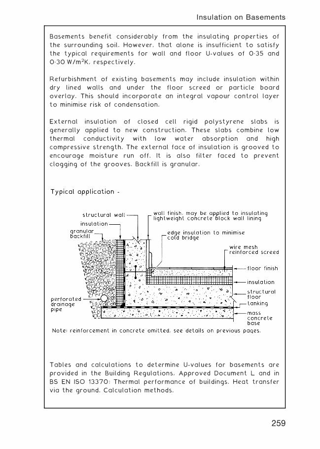
Basements benefit considerably from the insulating properties of
the surrounding soil. However, that alone is insufficient to satisfy
the typical requirements for wall and floor U-values of 0„35 and
0„30 W/m2K, respectively.
Refurbishment of existing basements may include insulation within
dry lined walls and under the floor screed or particle board
overlay. This should incorporate an integral vapour control layer
to minimise risk of condensation.
External insulation of closed cell rigid polystyrene slabs is
generally applied to new construction. These slabs combine low
thermal conductivity with low water absorption and high
compressive strength. The external face of insulation is grooved to
encourage moisture run off. It is also filter faced to prevent
clogging of the grooves. Backfill is granular.
Tables and calculations to determine U-values for basements are
provided in the Building Regulations, Approved Document L and in
BS EN ISO 13370: Thermal performance of buildings. Heat transfer
via the ground. Calculation methods.
259
Insulation on Basements
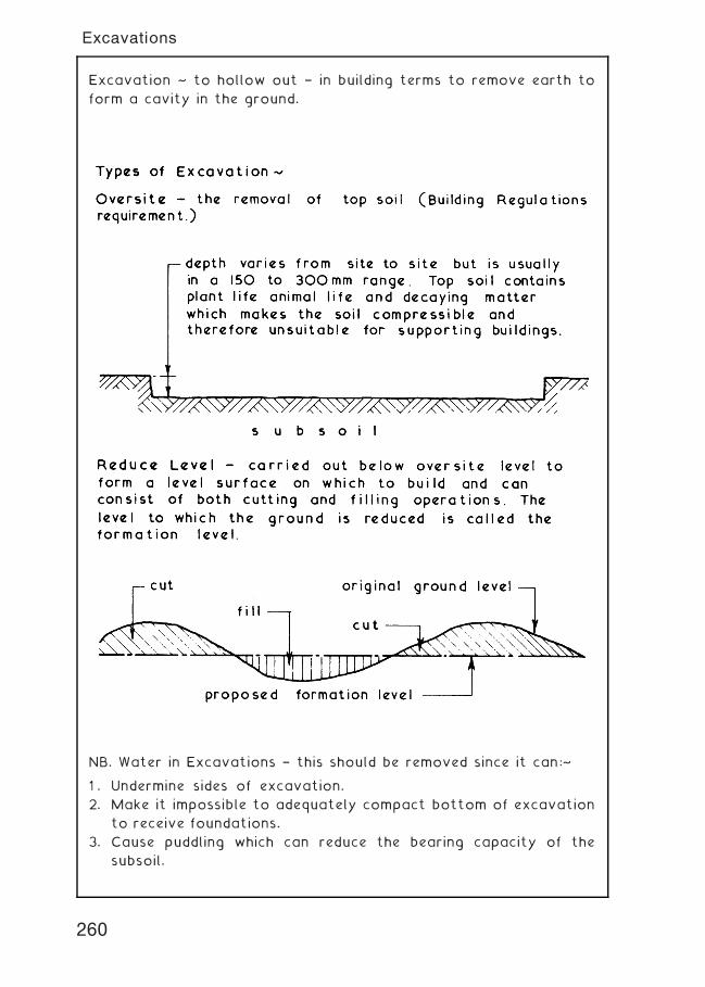
Excavation ~ to hollow out † in building terms to remove earth to
form a cavity in the ground.
NB. Water in Excavations † this should be removed since it can:~
1 . Undermine sides of excavation.
2. Make it impossible to adequately compact bottom of excavation
to receive foundations.
3. Cause puddling which can reduce the bearing capacity of the
subsoil.
260
Excavations
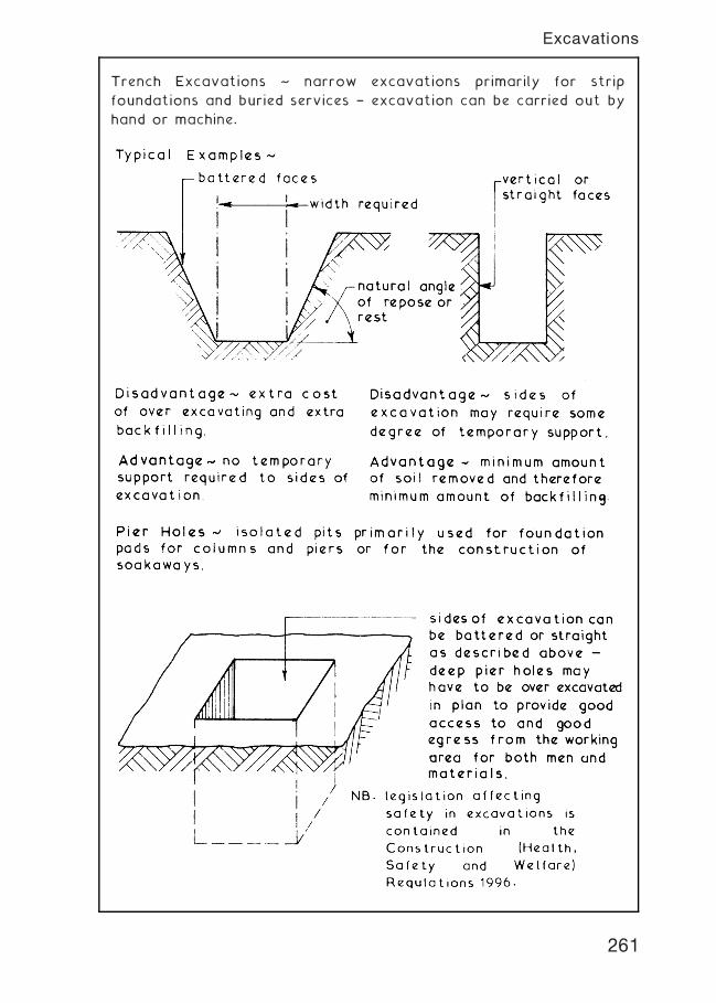
Trench Excavations ~ narrow excavations primarily for strip
foundations and buried services † excavation can be carried out by
hand or machine.
261
Excavations
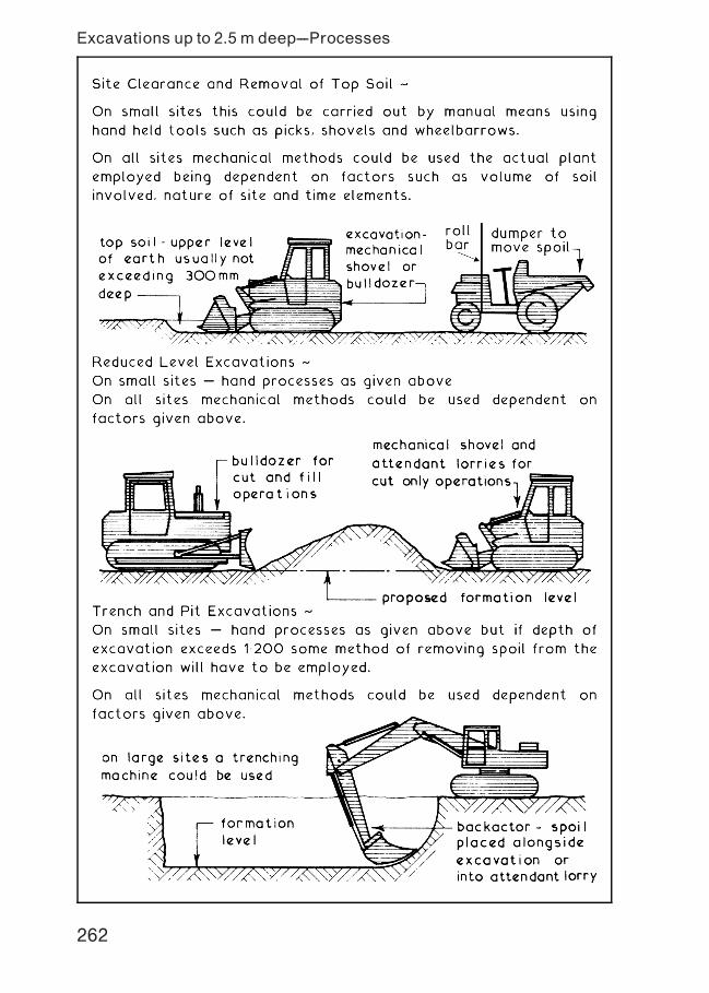
Excavations up to 2.5 m deep---Processes
262
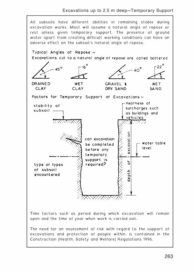
All subsoils have different abilities in remaining stable during
excavation works. Most will assume a natural angle of repose or
rest unless given temporary support. The presence of ground
water apart from creating difficult working conditions can have an
adverse effect on the subsoil's natural angle of repose.
Time factors such as period during which excavation will remain
open and the time of year when work is carried out.
The need for an assessment of risk with regard to the support of
excavations and protection of people within, is contained in the
Construction (Health, Safety and Welfare) Regulations 1996.
263
Excavations up to 2.5 m deep---Temporary Support
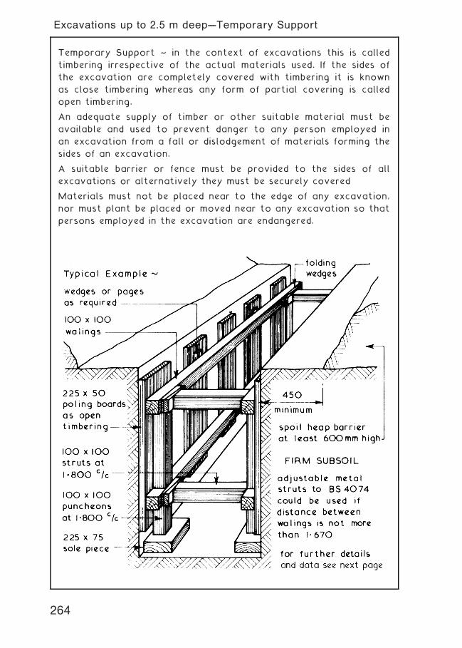
Temporary Support ~ in the context of excavations this is called
timbering irrespective of the actual materials used. If the sides of
the excavation are completely covered with timbering it is known
as close timbering whereas any form of partial covering is called
open timbering.
An adequate supply of timber or other suitable material must be
available and used to prevent danger to any person employed in
an excavation from a fall or dislodgement of materials forming the
sides of an excavation.
A suitable barrier or fence must be provided to the sides of all
excavations or alternatively they must be securely covered
Materials must not be placed near to the edge of any excavation,
nor must plant be placed or moved near to any excavation so that
persons employed in the excavation are endangered.
264
Excavations up to 2.5 m deep---Temporary Support
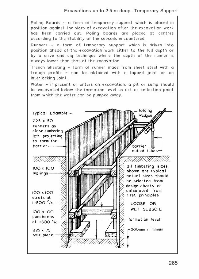
Poling Boards ~ a form of temporary support which is placed in
position against the sides of excavation after the excavation work
has been carried out. Poling boards are placed at centres
according to the stability of the subsoils encountered.
Runners ~ a form of temporary support which is driven into
position ahead of the excavation work either to the full depth or
by a drive and dig technique where the depth of the runner is
always lower than that of the excavation.
Trench Sheeting ~ form of runner made from sheet steel with a
trough profile † can be obtained with a lapped joint or an
interlocking joint.
Water ~ if present or enters an excavation, a pit or sump should
be excavated below the formation level to act as collection point
from which the water can be pumped away.
265
Excavations up to 2.5 m deep---Temporary Support
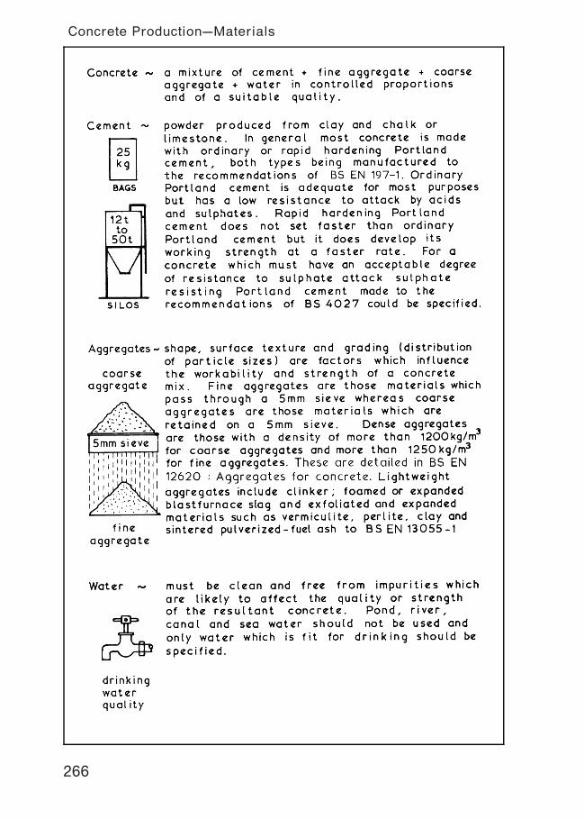
266
Concrete Production---Materials
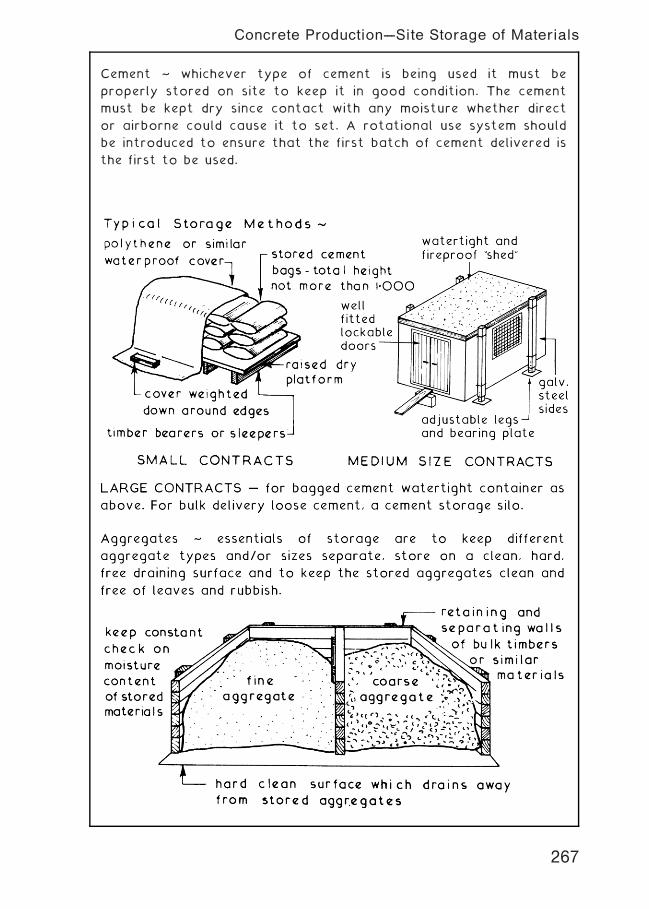
Cement ~ whichever type of cement is being used it must be
properly stored on site to keep it in good condition. The cement
must be kept dry since contact with any moisture whether direct
or airborne could cause it to set. A rotational use system should
be introduced to ensure that the first batch of cement delivered is
the first to be used.
267
Concrete Production---Site Storage of Materials
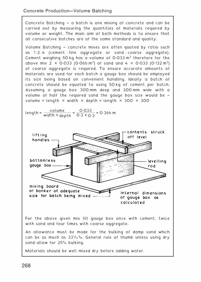
Concrete Batching ~ a batch is one mixing of concrete and can be
carried out by measuring the quantities of materials required by
volume or weight. The main aim of both methods is to ensure that
all consecutive batches are of the same standard and quality.
Volume Batching ~ concrete mixes are often quoted by ratio such
as 1 :2 :4 (cement : fine aggregate or sand : coarse aggregate).
Cement weighing 50 kg has a volume of 0„033 m3 therefore for the
above mix 2 � 0„033 (0„066 m3) of sand and 4 � 0„033 (0„132 m3)
of coarse aggregate is required. To ensure accurate amounts of
materials are used for each batch a gauge box should be employed
its size being based on convenient handling. Ideally a batch of
concrete should be equated to using 50 kg of cement per batch.
Assuming a gauge box 300 mm deep and 300mm wide with a
volume of half the required sand the gauge box size would be †
volume = length � width � depth = length � 300 � 300
length =volume
width � depth=
0„0330„3 � 0„3
= 0„366 m
For the above given mix fill gauge box once with cement, twice
with sand and four times with coarse aggregate.
An allowance must be made for the bulking of damp sand which
can be as much as 331/3%. General rule of thumb unless using dry
sand allow for 25% bulking.
Materials should be well mixed dry before adding water.
268
Concrete Production---Volume Batching
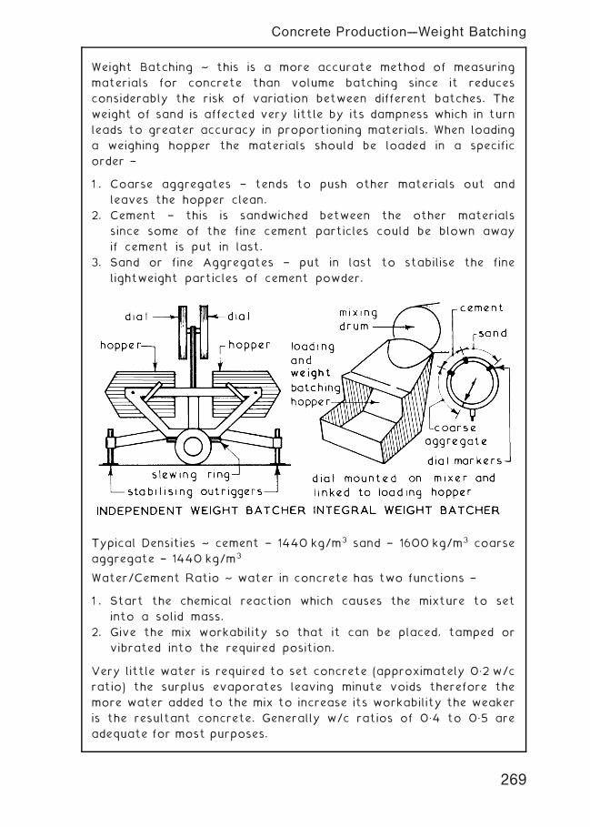
Weight Batching ~ this is a more accurate method of measuring
materials for concrete than volume batching since it reduces
considerably the risk of variation between different batches. The
weight of sand is affected very little by its dampness which in turn
leads to greater accuracy in proportioning materials. When loading
a weighing hopper the materials should be loaded in a specific
order †
1 . Coarse aggregates † tends to push other materials out and
leaves the hopper clean.
2. Cement † this is sandwiched between the other materials
since some of the fine cement particles could be blown away
if cement is put in last.
3. Sand or fine Aggregates † put in last to stabilise the fine
lightweight particles of cement powder.
Typical Densities ~ cement † 1440 kg/m3 sand † 1600 kg/m3 coarse
aggregate † 1440 kg/m3
Water/Cement Ratio ~ water in concrete has two functions †
1 . Start the chemical reaction which causes the mixture to set
into a solid mass.
2. Give the mix workability so that it can be placed, tamped or
vibrated into the required position.
Very little water is required to set concrete (approximately 0„2 w/c
ratio) the surplus evaporates leaving minute voids therefore the
more water added to the mix to increase its workability the weaker
is the resultant concrete. Generally w/c ratios of 0„4 to 0„5 are
adequate for most purposes.
269
Concrete Production---Weight Batching
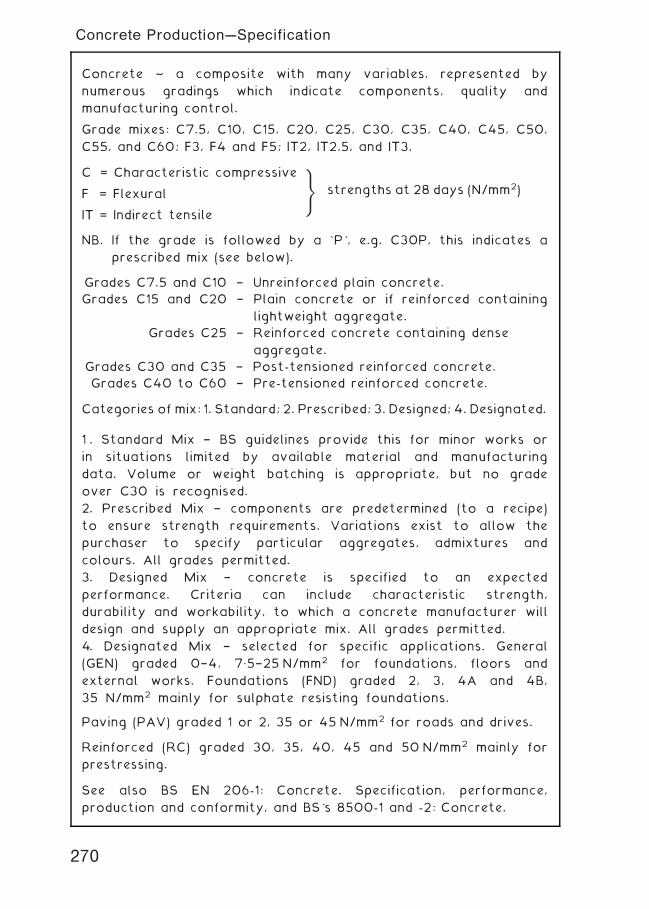
Concrete ~ a composite with many variables, represented by
numerous gradings which indicate components, quality and
manufacturing control.
Grade mixes: C7.5, C10, C15, C20, C25, C30, C35, C40, C45, C50,
C55, and C60; F3, F4 and F5; IT2, IT2.5, and IT3.
C = Characteristic compressive
F = Flexural
IT = Indirect tensile
NB. If the grade is followed by a `P', e.g. C30P, this indicates a
prescribed mix (see below).
Grades C7.5 and C10 † Unreinforced plain concrete.
Grades C15 and C20 † Plain concrete or if reinforced containing
lightweight aggregate.
Grades C25 † Reinforced concrete containing dense
aggregate.
Grades C30 and C35 † Post-tensioned reinforced concrete.
Grades C40 to C60 † Pre-tensioned reinforced concrete.
Categories of mix: 1. Standard; 2. Prescribed; 3. Designed; 4. Designated.
1 . Standard Mix † BS guidelines provide this for minor works or
in situations limited by available material and manufacturing
data. Volume or weight batching is appropriate, but no grade
over C30 is recognised.
2. Prescribed Mix † components are predetermined (to a recipe)
to ensure strength requirements. Variations exist to allow the
purchaser to specify particular aggregates, admixtures and
colours. All grades permitted.
3. Designed Mix † concrete is specified to an expected
performance. Criteria can include characteristic strength,
durability and workability, to which a concrete manufacturer will
design and supply an appropriate mix. All grades permitted.
4. Designated Mix † selected for specific applications. General
(GEN) graded 0†4, 7„5†25 N/mm2 for foundations, floors and
external works. Foundations (FND) graded 2, 3, 4A and 4B,
35 N/mm2 mainly for sulphate resisting foundations.
Paving (PAV) graded 1 or 2, 35 or 45 N/mm2 for roads and drives.
Reinforced (RC) graded 30, 35, 40, 45 and 50 N/mm2 mainly for
prestressing.
See also BS EN 206-1: Concrete. Specification, performance,
production and conformity, and BS's 8500-1 and -2: Concrete.
)
strengths at 28 days (N/mm2)
270
Concrete Production---Specification
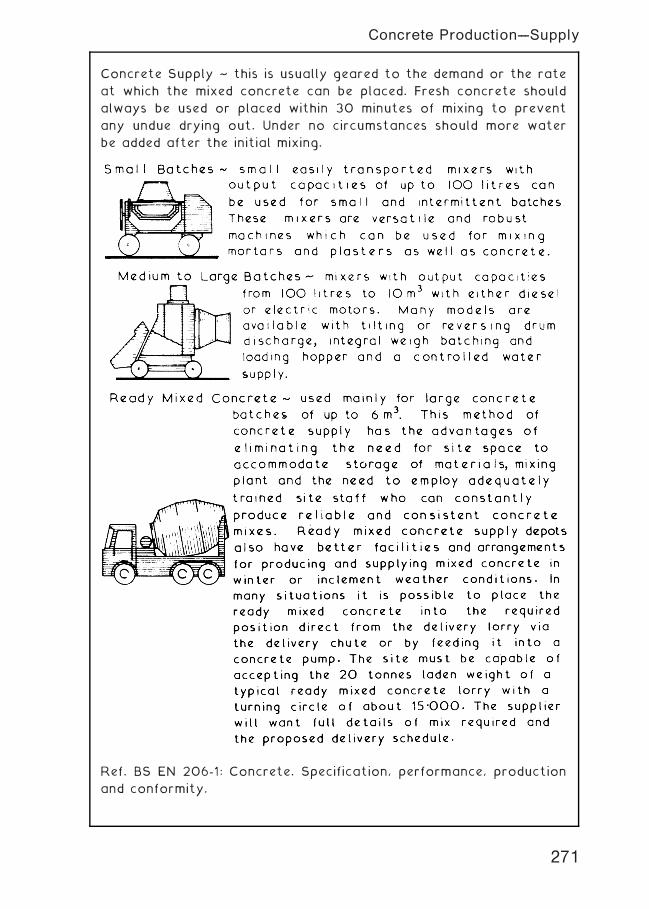
Concrete Supply ~ this is usually geared to the demand or the rate
at which the mixed concrete can be placed. Fresh concrete should
always be used or placed within 30 minutes of mixing to prevent
any undue drying out. Under no circumstances should more water
be added after the initial mixing.
Ref. BS EN 206-1: Concrete. Specification, performance, production
and conformity.
271
Concrete Production---Supply
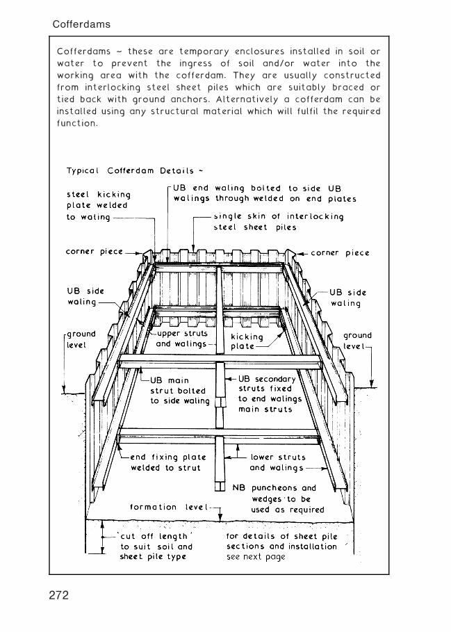
Cofferdams ~ these are temporary enclosures installed in soil or
water to prevent the ingress of soil and/or water into the
working area with the cofferdam. They are usually constructed
from interlocking steel sheet piles which are suitably braced or
tied back with ground anchors. Alternatively a cofferdam can be
installed using any structural material which will fulfil the required
function.
272
Cofferdams
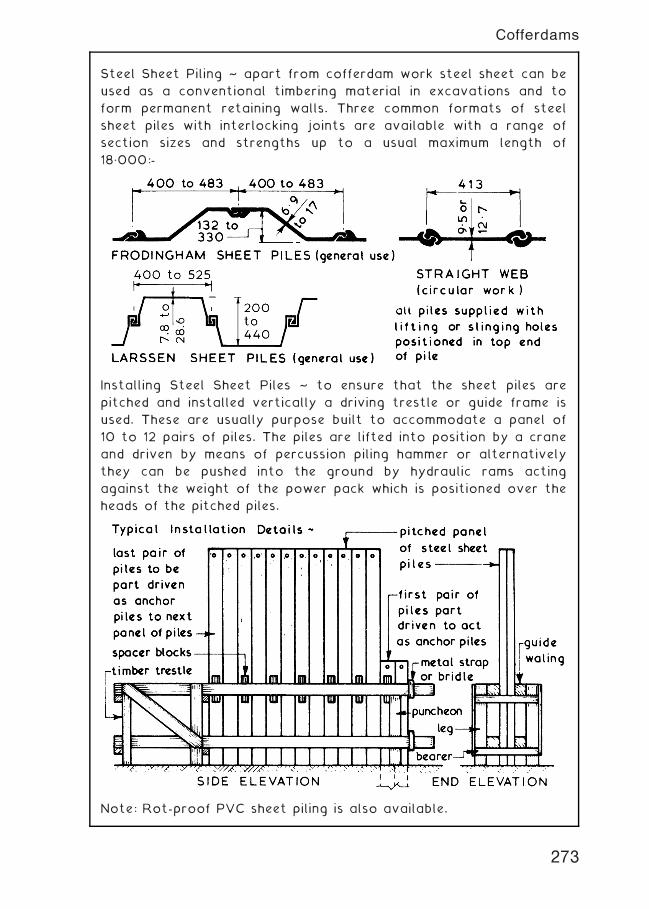
Steel Sheet Piling ~ apart from cofferdam work steel sheet can be
used as a conventional timbering material in excavations and to
form permanent retaining walls. Three common formats of steel
sheet piles with interlocking joints are available with a range of
section sizes and strengths up to a usual maximum length of
18„000:-
Installing Steel Sheet Piles ~ to ensure that the sheet piles are
pitched and installed vertically a driving trestle or guide frame is
used. These are usually purpose built to accommodate a panel of
10 to 12 pairs of piles. The piles are lifted into position by a crane
and driven by means of percussion piling hammer or alternatively
they can be pushed into the ground by hydraulic rams acting
against the weight of the power pack which is positioned over the
heads of the pitched piles.
Note: Rot-proof PVC sheet piling is also available.
273
Cofferdams
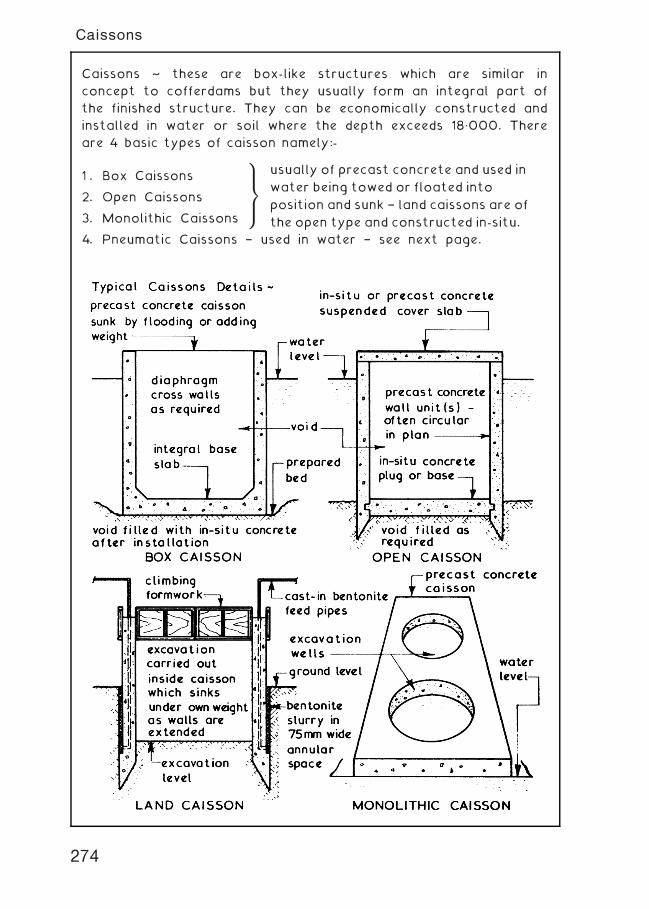
Caissons ~ these are box-like structures which are similar in
concept to cofferdams but they usually form an integral part of
the finished structure. They can be economically constructed and
installed in water or soil where the depth exceeds 18„000. There
are 4 basic types of caisson namely:-
1 . Box Caissons
2. Open Caissons
3. Monolithic Caissons
4. Pneumatic Caissons † used in water † see next page.
9
>
=
>
;
usually of precast concrete and used in
water being towed or floated into
position and sunk † land caissons are of
the open type and constructed in-situ.
274
Caissons
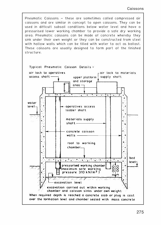
Pneumatic Caissons ~ these are sometimes called compressed air
caissons and are similar in concept to open caissons. They can be
used in difficult subsoil conditions below water level and have a
pressurised lower working chamber to provide a safe dry working
area. Pneumatic caissons can be made of concrete whereby they
sink under their own weight or they can be constructed from steel
with hollow walls which can be filled with water to act as ballast.
These caissons are usually designed to form part of the finished
structure.
275
Caissons
Underpinning ~ the main objective of most underpinning work is to
transfer the load carried by a foundation from its existing bearing
level to a new level at a lower depth. Underpinning techniques can
also be used to replace an existing weak foundation. An
underpinning operation may be necessary for one or more of the
following reasons:-
1. Uneven Settlement † this could be caused by uneven loading
of the building, unequal resistance of the soil action of tree
roots or cohesive soil settlement.
2. Increase in Loading † this could be due to the addition of an
extra storey or an increase in imposed loadings such as that
which may occur with a change of use.
3. Lowering of Adjacent Ground † usually required when
constructing a basement adjacent to existing foundations.
General Precautions ~ before any form of underpinning work is
commenced the following precautions should be taken:-
1. Notify adjoining owners of proposed works giving full details
and temporary shoring or tying.
2. Carry out a detailed survey of the site, the building to be
underpinned and of any other adjoining or adjacent building
or structures. A careful record of any defects found should
be made and where possible agreed with the adjoining
owner(s) before being lodged in a safe place.
3. Indicators or `tell tales' should be fixed over existing cracks
so that any subsequent movements can be noted and
monitored.
4. If settlement is the reason for the underpinning works a
thorough investigation should be carried out to establish the
cause and any necessary remedial work put in hand before
any underpinning works are started.
5. Before any underpinning work is started the loads on the
building to be underpinned should be reduced as much as
possible by removing the imposed loads from the floors and
installing any props and/or shoring which is required.
6. Any services which are in the vicinity of the proposed
underpinning works should be identified, traced, carefully
exposed, supported and protected as necessary.
276
Underpinning
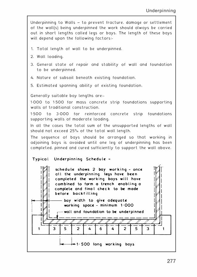
Underpinning to Walls ~ to prevent fracture, damage or settlement
of the wall(s) being underpinned the work should always be carried
out in short lengths called legs or bays. The length of these bays
will depend upon the following factors:-
1. Total length of wall to be underpinned.
2. Wall loading.
3. General state of repair and stability of wall and foundation
to be underpinned.
4. Nature of subsoil beneath existing foundation.
5. Estimated spanning ability of existing foundation.
Generally suitable bay lengths are:-
1„000 to 1„500 for mass concrete strip foundations supporting
walls of traditional construction.
1„500 to 3„000 for reinforced concrete strip foundations
supporting walls of moderate loading.
In all the cases the total sum of the unsupported lengths of wall
should not exceed 25% of the total wall length.
The sequence of bays should be arranged so that working in
adjoining bays is avoided until one leg of underpinning has been
completed, pinned and cured sufficiently to support the wall above.
277
Underpinning
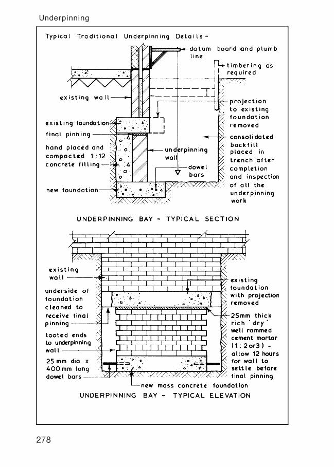
278
Underpinning
Jack Pile Underpinning ~ this method can be used when the depth
of a suitable bearing capacity subsoil is too deep to make
traditional underpinning uneconomic. Jack pile underpinning is quiet,
vibration free and flexible since the pile depth can be adjusted to
suit subsoil conditions encountered. The existing foundations must
be in a good condition since they will have to span over the heads
of the pile caps which are cast onto the jack pile heads after the
hydraulic jacks have been removed.
279
Underpinning
Needle and Pile Underpinning ~ this method of underpinning can be
used where the condition of the existing foundation is unsuitable
for traditional or jack pile underpinning techniques. The brickwork
above the existing foundation must be in a sound condition since
this method relies on the `arching effect' of the brick bonding to
transmit the wall loads onto the needles and ultimately to the
piles. The piles used with this method are usually small diameter
bored piles † see page 214.
280
Underpinning
`Pynford' Stool Method of Underpinning ~ this method can be used
where the existing foundations are in a poor condition and it
enables the wall to be underpinned in a continuous run without the
need for needles or shoring. The reinforced concrete beam formed
by this method may well be adequate to spread the load of the
existing wall or it may be used in conjunction with other forms of
underpinning such as traditional and jack pile.
281
Underpinning
Root Pile or Angle Piling ~ this is a much simpler alternative to
traditional underpinning techniques, applying modern concrete
drilling equipment to achieve cost benefits through time saving. The
process is also considerably less disruptive, as large volumes of
excavation are avoided. Where sound bearing strata can be located
within a few metres of the surface, wall stability is achieved
through lined reinforced concrete piles installed in pairs, at
opposing angles. The existing floor, wall and foundation are pre-
drilled with air flushed percussion auger, giving access for a steel
lining to be driven through the low grade/clay subsoil until it
impacts with firm strata. The lining is cut to terminate at the
underside of the foundation and the void steel reinforced prior to
concreting.
In many situations it is impractical to apply angle piling to both
sides of a wall. Subject to subsoil conditions being adequate, it
may be acceptable to apply remedial treatment from one side only.
The piles will need to be relatively close spaced.
282
Underpinning
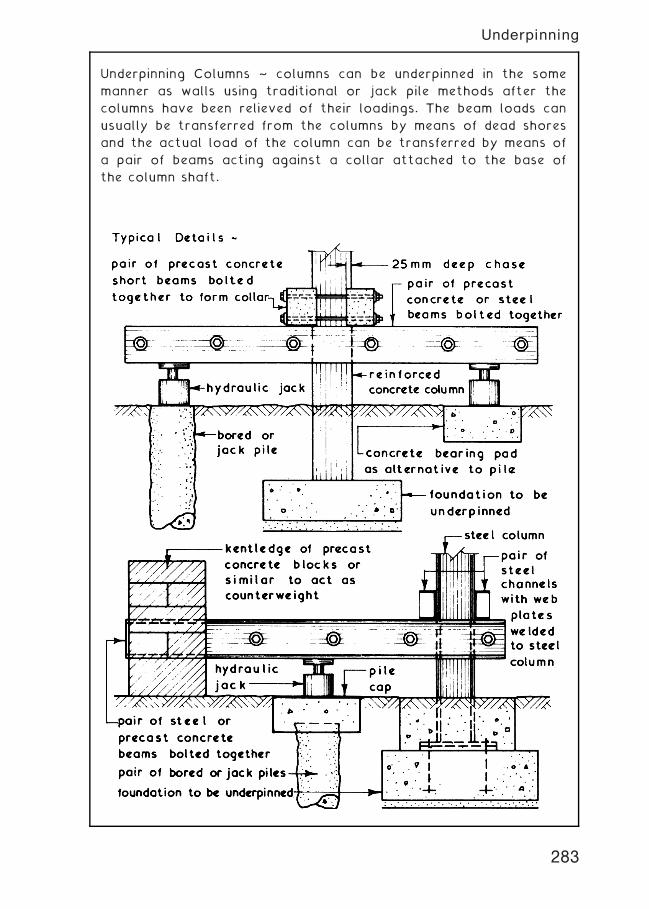
Underpinning Columns ~ columns can be underpinned in the some
manner as walls using traditional or jack pile methods after the
columns have been relieved of their loadings. The beam loads can
usually be transferred from the columns by means of dead shores
and the actual load of the column can be transferred by means of
a pair of beams acting against a collar attached to the base of
the column shaft.
283
Underpinning
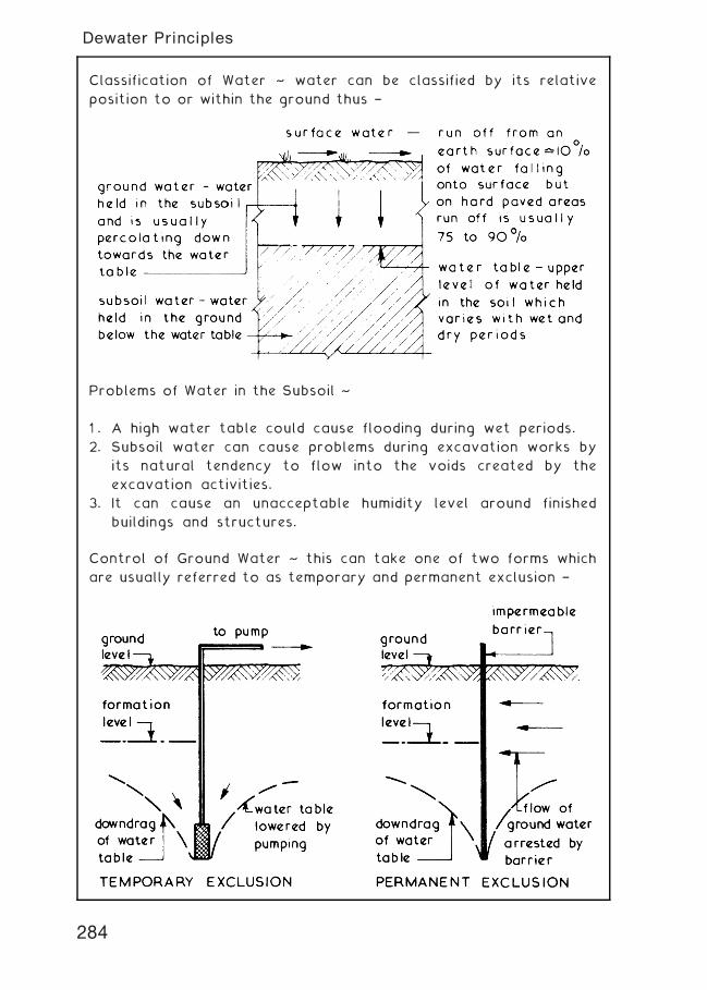
Classification of Water ~ water can be classified by its relative
position to or within the ground thus †
Problems of Water in the Subsoil ~
1 . A high water table could cause flooding during wet periods.
2. Subsoil water can cause problems during excavation works by
its natural tendency to flow into the voids created by the
excavation activities.
3. It can cause an unacceptable humidity level around finished
buildings and structures.
Control of Ground Water ~ this can take one of two forms which
are usually referred to as temporary and permanent exclusion †
284
Dewater Principles
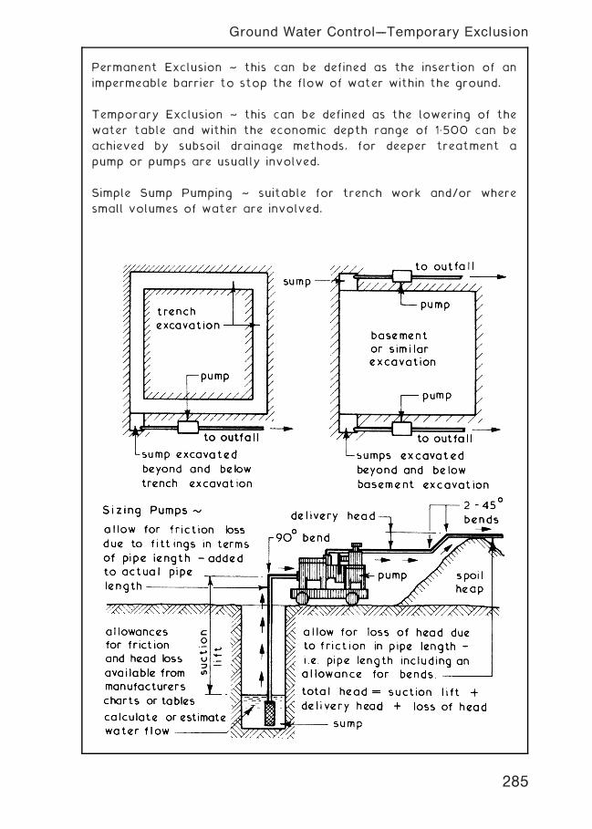
Permanent Exclusion ~ this can be defined as the insertion of an
impermeable barrier to stop the flow of water within the ground.
Temporary Exclusion ~ this can be defined as the lowering of the
water table and within the economic depth range of 1„500 can be
achieved by subsoil drainage methods, for deeper treatment a
pump or pumps are usually involved.
Simple Sump Pumping ~ suitable for trench work and/or where
small volumes of water are involved.
285
Ground Water Control---Temporary Exclusion
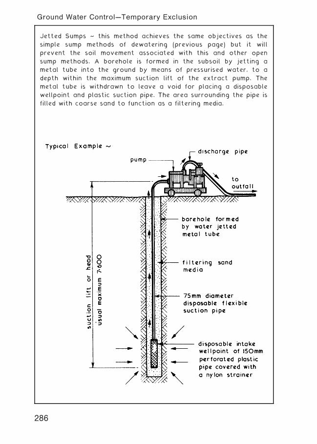
Jetted Sumps ~ this method achieves the same objectives as the
simple sump methods of dewatering (previous page) but it will
prevent the soil movement associated with this and other open
sump methods. A borehole is formed in the subsoil by jetting a
metal tube into the ground by means of pressurised water, to a
depth within the maximum suction lift of the extract pump. The
metal tube is withdrawn to leave a void for placing a disposable
wellpoint and plastic suction pipe. The area surrounding the pipe is
filled with coarse sand to function as a filtering media.
286
Ground Water Control---Temporary Exclusion
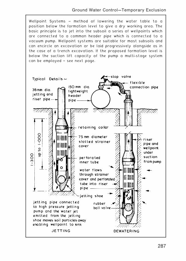
Wellpoint Systems ~ method of lowering the water table to a
position below the formation level to give a dry working area. The
basic principle is to jet into the subsoil a series of wellpoints which
are connected to a common header pipe which is connected to a
vacuum pump. Wellpoint systems are suitable for most subsoils and
can encircle an excavation or be laid progressively alongside as in
the case of a trench excavation. If the proposed formation level is
below the suction lift capacity of the pump a multi-stage system
can be employed † see next page.
287
Ground Water Control---Temporary Exclusion
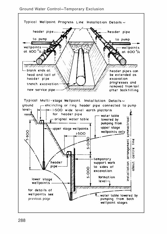
288
Ground Water Control---Temporary Exclusion
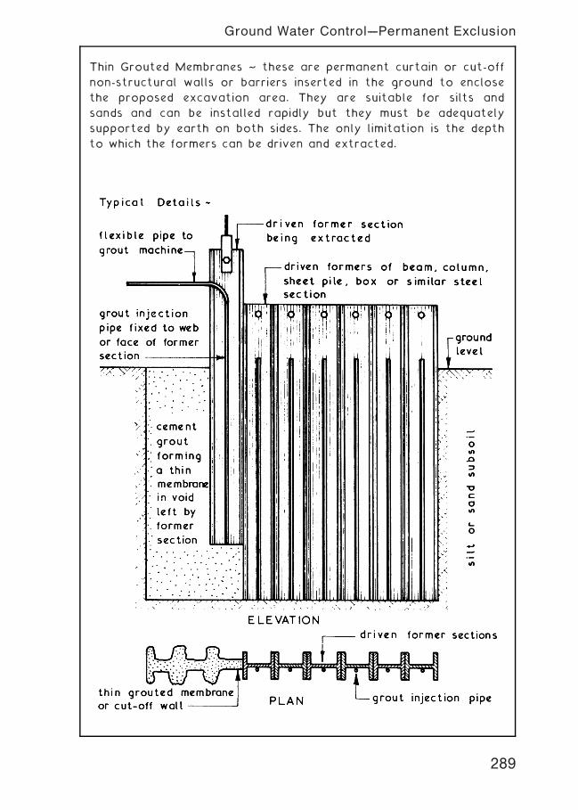
Thin Grouted Membranes ~ these are permanent curtain or cut-off
non-structural walls or barriers inserted in the ground to enclose
the proposed excavation area. They are suitable for silts and
sands and can be installed rapidly but they must be adequately
supported by earth on both sides. The only limitation is the depth
to which the formers can be driven and extracted.
289
Ground Water Control---Permanent Exclusion
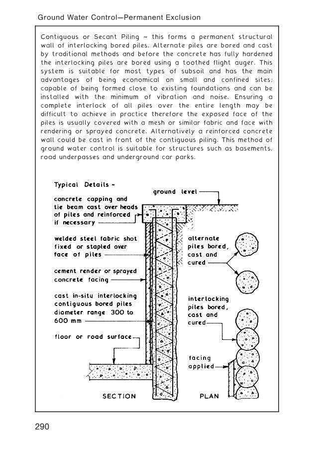
Contiguous or Secant Piling ~ this forms a permanent structural
wall of interlocking bored piles. Alternate piles are bored and cast
by traditional methods and before the concrete has fully hardened
the interlocking piles are bored using a toothed flight auger. This
system is suitable for most types of subsoil and has the main
advantages of being economical on small and confined sites;
capable of being formed close to existing foundations and can be
installed with the minimum of vibration and noise. Ensuring a
complete interlock of all piles over the entire length may be
difficult to achieve in practice therefore the exposed face of the
piles is usually covered with a mesh or similar fabric and face with
rendering or sprayed concrete. Alternatively a reinforced concrete
wall could be cast in front of the contiguous piling. This method of
ground water control is suitable for structures such as basements,
road underpasses and underground car parks.
290
Ground Water Control---Permanent Exclusion
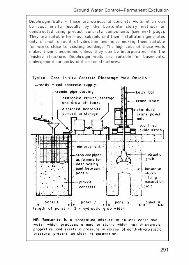
Diaphragm Walls ~ these are structural concrete walls which can
be cast in-situ (usually by the bentonite slurry method) or
constructed using precast concrete components (see next page).
They are suitable for most subsoils and their installation generates
only a small amount of vibration and noise making them suitable
for works close to existing buildings. The high cost of these walls
makes them uneconomic unless they can be incorporated into the
finished structure. Diaphragm walls are suitable for basements,
underground car parks and similar structures.
291
Ground Water Control---Permanent Exclusion
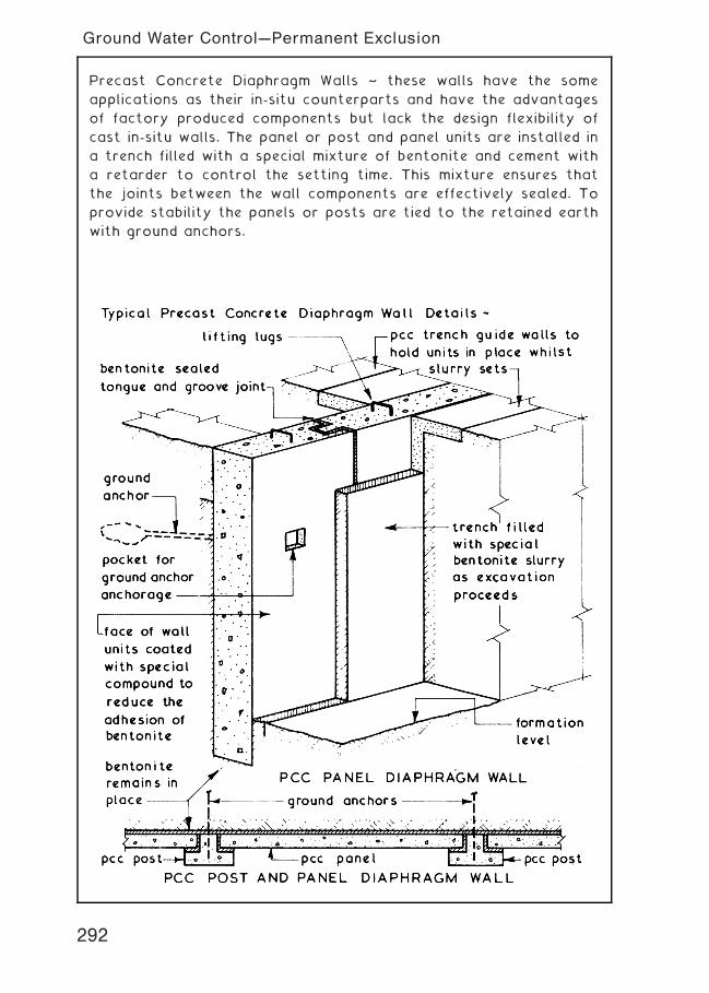
Precast Concrete Diaphragm Walls ~ these walls have the some
applications as their in-situ counterparts and have the advantages
of factory produced components but lack the design flexibility of
cast in-situ walls. The panel or post and panel units are installed in
a trench filled with a special mixture of bentonite and cement with
a retarder to control the setting time. This mixture ensures that
the joints between the wall components are effectively sealed. To
provide stability the panels or posts are tied to the retained earth
with ground anchors.
292
Ground Water Control---Permanent Exclusion
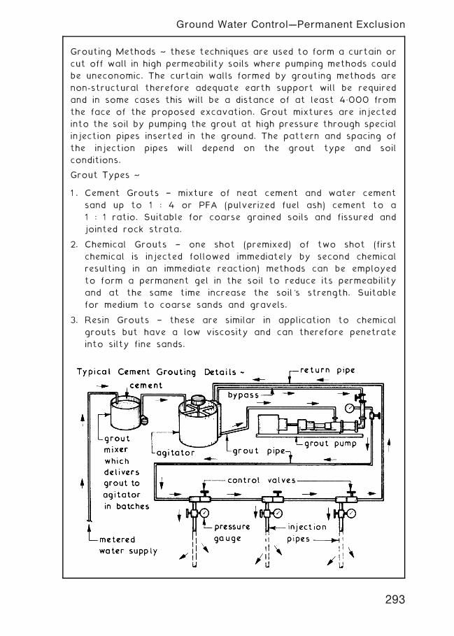
Grouting Methods ~ these techniques are used to form a curtain or
cut off wall in high permeability soils where pumping methods could
be uneconomic. The curtain walls formed by grouting methods are
non-structural therefore adequate earth support will be required
and in some cases this will be a distance of at least 4„000 from
the face of the proposed excavation. Grout mixtures are injected
into the soil by pumping the grout at high pressure through special
injection pipes inserted in the ground. The pattern and spacing of
the injection pipes will depend on the grout type and soil
conditions.
Grout Types ~
1 . Cement Grouts † mixture of neat cement and water cement
sand up to 1 : 4 or PFA (pulverized fuel ash) cement to a
1 : 1 ratio. Suitable for coarse grained soils and fissured and
jointed rock strata.
2. Chemical Grouts † one shot (premixed) of two shot (first
chemical is injected followed immediately by second chemical
resulting in an immediate reaction) methods can be employed
to form a permanent gel in the soil to reduce its permeability
and at the same time increase the soil's strength. Suitable
for medium to coarse sands and gravels.
3. Resin Grouts † these are similar in application to chemical
grouts but have a low viscosity and can therefore penetrate
into silty fine sands.
293
Ground Water Control---Permanent Exclusion

Ground Freezing Techniques ~ this method is suitable for all types
of saturated soils and rock and for soils with a moisture content in
excess of 8% of the voids. The basic principle is to insert into the
ground a series of freezing tubes to form an ice wall thus creating
an impermeable barrier. The treatment takes time to develop and
the initial costs are high, therefore it is only suitable for large
contracts of reasonable duration. The freezing tubes can be
installed vertically for conventional excavations and horizontally
for tunnelling works. The usual circulating brines employed are
magnesium chloride and calcium chloride with a temperature of �15�
to �25�C which would take 10 to 17 days to form an ice wall 1„000
thick. Liquid nitrogen could be used as the freezing medium to
reduce the initial freezing period if the extra cost can be justified.
294
Ground Water Control---Medium Term Exclusion

Soil Investigation ~ before a decision is made as to the type of
foundation which should be used on any particular site a soil
investigation should be carried out to establish existing ground
conditions and soil properties. The methods which can be employed
together with other sources of information such as local
knowledge, ordnance survey and geological maps, mining records
and aerial photography should be familiar to students at this level.
If such an investigation reveals a naturally poor subsoil or
extensive filling the designer has several options:-
1. Not to Build † unless a new and suitable site can be found
building is only possible if the poor ground is localised and
the proposed foundations can be designed around these areas
with the remainder of the structure bridging over these
positions.
2. Remove and Replace † the poor ground can be excavated,
removed and replaced by compacted fills. Using this method
there is a risk of differential settlement and generally for
depths over 4„000 it is uneconomic.
3. Surcharging † this involves preloading the poor ground with a
surcharge of aggregate or similar material to speed up
settlement and thereby improve the soil's bearing capacity.
Generally this method is uneconomic due to the time delay
before actual building operations can commence which can
vary from a few weeks to two or more years.
4. Vibration † this is a method of strengthening ground by
vibrating a granular soil into compacted stone columns either
by using the natural coarse granular soil or by replacement †
see pages 296 and 297.
5. Dynamic Compaction † this is a method of soil improvement
which consists of dropping a heavy weight through a
considerable vertical distance to compact the soil and thus
improve its bearing capacity and is especially suitable for
granular soils † see page 298.
6. Jet Grouting † this method of consolidating ground can be
used in all types of subsoil and consists of lowering a monitor
probe into a 150 mm diameter prebored guide hole. The probe
has two jets the upper of which blasts water, concentrated by
compressed air to force any loose material up the guide to
ground level. The lower jet fills the void with a cement slurry
which sets into a solid mass † see page 299.
295
Soil Stabilisation and Improvement
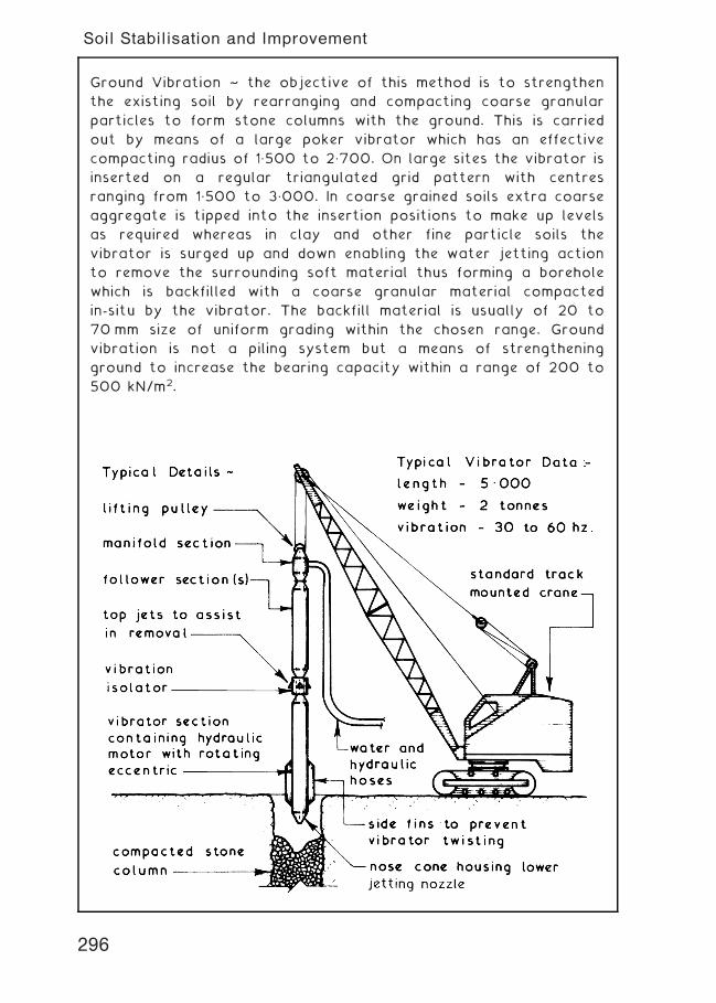
Ground Vibration ~ the objective of this method is to strengthen
the existing soil by rearranging and compacting coarse granular
particles to form stone columns with the ground. This is carried
out by means of a large poker vibrator which has an effective
compacting radius of 1„500 to 2„700. On large sites the vibrator is
inserted on a regular triangulated grid pattern with centres
ranging from 1„500 to 3„000. In coarse grained soils extra coarse
aggregate is tipped into the insertion positions to make up levels
as required whereas in clay and other fine particle soils the
vibrator is surged up and down enabling the water jetting action
to remove the surrounding soft material thus forming a borehole
which is backfilled with a coarse granular material compacted
in-situ by the vibrator. The backfill material is usually of 20 to
70 mm size of uniform grading within the chosen range. Ground
vibration is not a piling system but a means of strengthening
ground to increase the bearing capacity within a range of 200 to
500 kN/m2.
296
Soil Stabilisation and Improvement
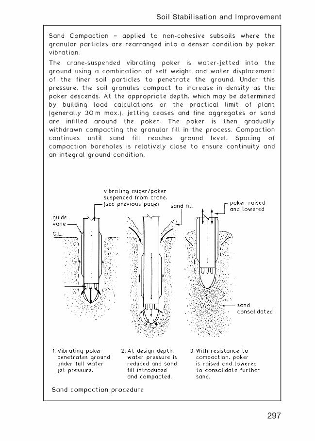
Sand Compaction † applied to non-cohesive subsoils where the
granular particles are rearranged into a denser condition by poker
vibration.
The crane-suspended vibrating poker is water-jetted into the
ground using a combination of self weight and water displacement
of the finer soil particles to penetrate the ground. Under this
pressure, the soil granules compact to increase in density as the
poker descends. At the appropriate depth, which may be determined
by building load calculations or the practical limit of plant
(generally 30 m max.), jetting ceases and fine aggregates or sand
are infilled around the poker. The poker is then gradually
withdrawn compacting the granular fill in the process. Compaction
continues until sand fill reaches ground level. Spacing of
compaction boreholes is relatively close to ensure continuity and
an integral ground condition.
297
Soil Stabilisation and Improvement
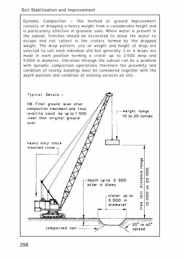
Dynamic Compaction ~ this method of ground improvement
consists of dropping a heavy weight from a considerable height and
is particularly effective in granular soils. Where water is present in
the subsoil, trenches should be excavated to allow the water to
escape and not collect in the craters formed by the dropped
weight. The drop pattern, size of weight and height of drop are
selected to suit each individual site but generally 3 or 4 drops are
made in each position forming a crater up to 2„500 deep and
5„000 in diameter. Vibration through the subsoil can be a problem
with dynamic compaction operations therefore the proximity and
condition of nearby buildings must be considered together with the
depth position and condition of existing services on site.
298
Soil Stabilisation and Improvement
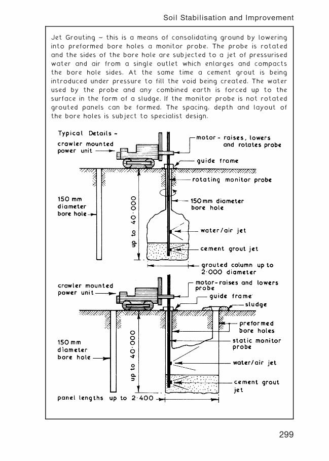
Jet Grouting ~ this is a means of consolidating ground by lowering
into preformed bore holes a monitor probe. The probe is rotated
and the sides of the bore hole are subjected to a jet of pressurised
water and air from a single outlet which enlarges and compacts
the bore hole sides. At the same time a cement grout is being
introduced under pressure to fill the void being created. The water
used by the probe and any combined earth is forced up to the
surface in the form of a sludge. If the monitor probe is not rotated
grouted panels can be formed. The spacing, depth and layout of
the bore holes is subject to specialist design.
299
Soil Stabilisation and Improvement
Green-Field † land not previously built upon. Usually part of the
`green†belt' surrounding urban areas, designated inappropriate
for development in order to preserve the countryside. Limited
development for agricultural purposes only may be permitted on
`green-belt' land.
Brown-Field † derelict land formerly a developed site and usually
associated with previous construction of industrial buildings. UK
government has set an objective to build 60% of the 4 million new
homes required by 2016 on these sites.
Site Survey † essential that a geo†technical survey is undertaken
to determine whether contaminants are in the soil and ground
water. Of particular concern are: acids, salts, heavy metals,
cyanides and coal tars, in addition to organic materials which
decompose to form the highly explosive gas, methane. Analysis of
the soil will determine a `trigger threshold value', above which it
will be declared sensitive to the end user. For example, a domestic
garden or children's play area will have a low value relative to
land designated for a commercial car park.
Site Preparation † when building on sites previously infilled with
uncontaminated material, a reinforced raft type foundation may be
adequate for light structures. Larger buildings will justify soil
consolidation and compaction processes to improve the bearing
capacity. Remedial measures for subsoils containing chemicals or
other contaminants are varied.
Legislation † the Environment Protection Act of 1990 attempted
to enforce responsibility on local authorities to compile a register
of all potentially contaminated land. This proved unrealistic and
too costly due to inherent complexities. Since then, requirements
under the Environment Act 1995, the Pollution Prevention and
Control Act 1999, the PPC Regulations 2000 and the subsequent
DCLG Planning Policy Statement (PPS 23, 2004): Planning and
Pollution Control (Annex 2: Development of land affected by
contamination), have made this more of a planning issue. It has
become the responsibility of developers to conduct site
investigations and to present details of proposed remedial
measures as part of their planning application.
300
Reclamation of Waste Land
The traditional low-technology method for dealing with
contaminated sites has been to excavate the soil and remove it to
places licensed for depositing. However, with the increase in
building work on brown-field sites, suitable dumps are becoming
scarce. Added to this is the reluctance of ground operators to
handle large volumes of this type of waste. Also, where
excavations exceed depths of about 5 m, it becomes less practical
and too expensive. Alternative physical, biological or chemical
methods of soil treatment may be considered.
Encapsulation † in-situ enclosure of the contaminated soil. A
perimeter trench is taken down to rock or other sound strata and
filled with an impervious agent such as Bentonite clay. An
impermeable horizontal capping is also required to link with the
trenches. A high-specification barrier is necessary where liquid or
gas contaminants are present as these can migrate quite easily. A
system of monitoring soil condition is essential as the barrier may
decay in time. Suitable for all types of contaminant.
Soil washing † involves extraction of the soil, sifting to remove
large objects and placing it in a scrubbing unit resembling a huge
concrete mixer. Within this unit water and detergents are added for
a basic wash process, before pressure spraying to dissolve
pollutants and to separate clay from silt. Eliminates fuels, metals
and chemicals.
Vapour extraction † used to remove fuels or industrial solvents
and other organic deposits. At variable depths, small diameter
boreholes are located at frequent intervals. Attached to these are
vacuum pipes to draw air through the contaminated soil. The
contaminants are collected at a vapour treatment processing
plant on the surface, treated and evaporated into the atmosphere.
This is a slow process and it may take several months to cleanse a
site.
Electrolysis † use of low voltage d.c. in the presence of metals.
Electricity flows between an anode and cathode, where metal ions
in water accumulate in a sump before pumping to the surface for
treatment.
301
Physical Treatment of Contaminated Sub-soil
BIOLOGICAL
Phytoremediation † the removal of contaminants by plants which
will absorb harmful chemicals from the ground. The plants are
subsequently harvested and destroyed. A variant uses fungal
degradation of the contaminants.
Bioremediation † stimulating the growth of naturally occurring
microbes. Microbes consume petrochemicals and oils, converting
them to water and carbon dioxide. Conditions must be right, i.e. a
temperature of at least 10�C with an adequate supply of nutrients
and oxygen. Untreated soil can be excavated and placed over
perforated piping, through which air is pumped to enhance the
process prior to the soil being replaced.
CHEMICAL
Oxidation † sub-soil boreholes are used for the pumped distribution
of liquid hydrogen peroxide or potassium permanganate. Chemicals
and fuel deposits convert to water and carbon dioxide.
Solvent extraction † the sub-soil is excavated and mixed with a
solvent to break down oils, grease and chemicals that do not
dissolve in water.
THERMAL
Thermal treatment (off site) † an incineration process involving the
use of a large heating container/oven. Soil is excavated, dried and
crushed prior to heating to 2500�C, where harmful chemicals are
removed by evaporation or fusion.
Thermal treatment (in-situ) † steam, hot water or hot air is
pressure-injected through the soil. Variations include electric
currents and radio waves to heat water in the ground to become
steam. Evaporates chemicals.
Ref. Building Regulations, Approved Document, C1: Site preparation
and resistance to contaminants. Section 1: Clearance or treatment
of unsuitable material. Section 2: Resistance to contaminants.
302
Biological, Chemical and Thermal Treatment of Contaminated Sub-soil
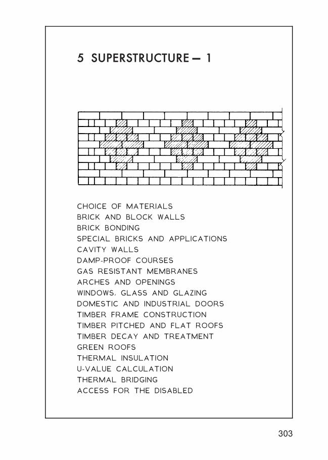
5 SUPERSTRUCTURE† 1
CHOICE OF MATERIALS
BRICK AND BLOCK WALLS
BRICK BONDING
SPECIAL BRICKS AND APPLICATIONS
CAVITY WALLS
DAMP-PROOF COURSES
GAS RESISTANT MEMBRANES
ARCHES AND OPENINGS
WINDOWS, GLASS AND GLAZING
DOMESTIC AND INDUSTRIAL DOORS
TIMBER FRAME CONSTRUCTION
TIMBER PITCHED AND FLAT ROOFS
TIMBER DECAY AND TREATMENT
GREEN ROOFS
THERMAL INSULATION
U-VALUE CALCULATION
THERMAL BRIDGING
ACCESS FOR THE DISABLED
303
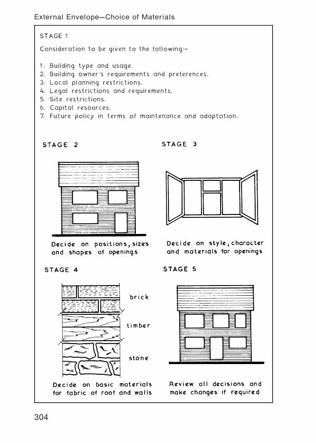
STAGE 1
Consideration to be given to the following:~
1 . Building type and usage.
2. Building owner's requirements and preferences.
3. Local planning restrictions.
4. Legal restrictions and requirements.
5. Site restrictions.
6. Capital resources.
7. Future policy in terms of maintenance and adaptation.
304
External Envelope---Choice of Materials
Bricks ~ these are walling units within a length of 337„5mm, a width
of 225mm and a height of 112„5mm. The usual size of bricks in
common use is length 215mm, width 102„5mm and height 65mm and
like blocks they must be laid in a definite pattern or bond if they
are to form a structural wall. Bricks are usually made from clay
(BS EN 772-1, BS EN 772-3 and BS EN 772-7) or from sand and lime
(BS EN 771-2) and are available in a wide variety of strengths,
types, textures, colours and special shaped bricks to BS 4729.
305
Solid Brick Walls
Typical Details ~
Bonding ~ an arrangement of bricks in a wall, column or pier laid
to a set pattern to maintain an adequate lap.
Purposes of Brick Bonding ~
1 . Obtain maximum strength whilst distributing the loads to be
carried throughout the wall, column or pier.
2. Ensure lateral stability and resistance to side thrusts.
3. Create an acceptable appearance.
Simple Bonding Rules ~
1 . Bond is set out along length of wall working from each end
to ensure that no vertical joints are above one another in
consecutive courses.
2. Walls which are not in exact bond length can be set out thus †
3. Transverse or cross joints
continue unbroken across the
width of wall unless stopped
by a face stretcher.
306
Brick Bonding---Principles
English Bond ~ formed by laying alternate courses of stretchers
and headers it is one of the strongest bonds but it will require
more facing bricks than other bonds (89 facing bricks per m2)
Typical Example ~
307
Brick Bonding---English Bond
Flemish Bond ~ formed by laying headers and stretchers alternately
in each course. Not as strong as English bond but is considered to
be aesthetically superior uses less facing bricks. (79 facing bricks
per m2)
Typical Example
308
Brick Bonding---Flemish Bond
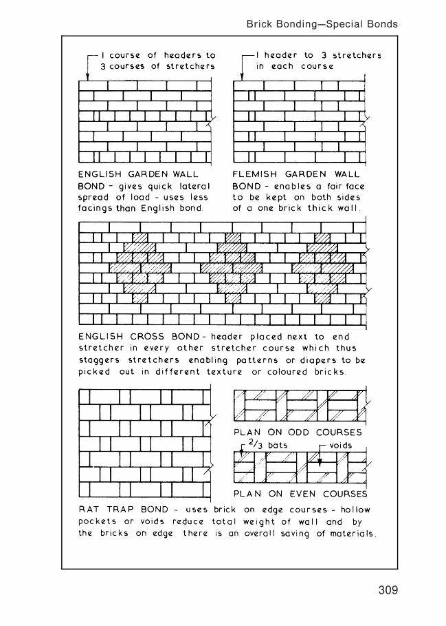
309
Brick Bonding---Special Bonds
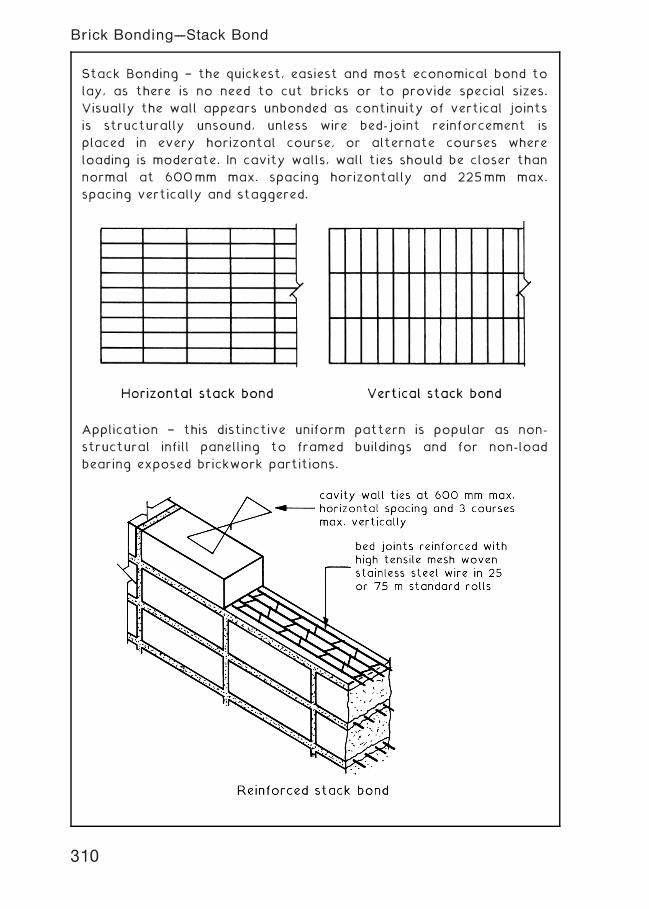
Stack Bonding † the quickest, easiest and most economical bond to
lay, as there is no need to cut bricks or to provide special sizes.
Visually the wall appears unbonded as continuity of vertical joints
is structurally unsound, unless wire bed-joint reinforcement is
placed in every horizontal course, or alternate courses where
loading is moderate. In cavity walls, wall ties should be closer than
normal at 600mm max. spacing horizontally and 225mm max.
spacing vertically and staggered.
Application † this distinctive uniform pattern is popular as non-
structural infill panelling to framed buildings and for non-load
bearing exposed brickwork partitions.
310
Brick Bonding---Stack Bond
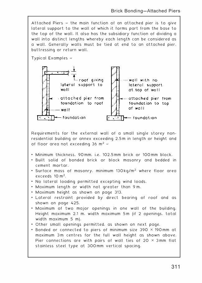
Attached Piers ~ the main function of an attached pier is to give
lateral support to the wall of which it forms part from the base to
the top of the wall. It also has the subsidiary function of dividing a
wall into distinct lengths whereby each length can be considered as
a wall. Generally walls must be tied at end to an attached pier,
buttressing or return wall.
Typical Examples ~
Requirements for the external wall of a small single storey non-
residential building or annex exceeding 2.5m in length or height and
of floor area not exceeding 36 m2 ~
• Minimum thickness, 90mm, i.e. 102.5mm brick or 100mm block.
• Built solid of bonded brick or block masonry and bedded in
cement mortar.
• Surface mass of masonry, minimum 130kg/m2 where floor area
exceeds 10 m2.
• No lateral loading permitted excepting wind loads.
• Maximum length or width not greater than 9 m.
• Maximum height as shown on page 313.
• Lateral restraint provided by direct bearing of roof and as
shown on page 425.
• Maximum of two major openings in one wall of the building.
Height maximum 2.1 m, width maximum 5m (if 2 openings, total
width maximum 5 m).
• Other small openings permitted, as shown on next page.
• Bonded or connected to piers of minimum size 390 5 190mm at
maximum 3m centres for the full wall height as shown above.
Pier connections are with pairs of wall ties of 20 5 3mm flat
stainless steel type at 300mm vertical spacing.
311
Brick Bonding---Attached Piers
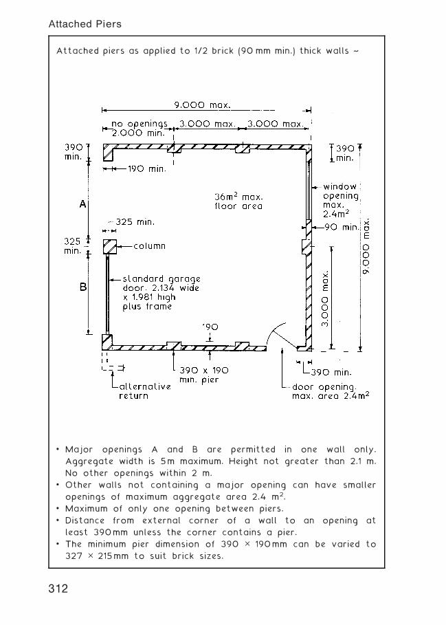
Attached piers as applied to 1/2 brick (90 mm min.) thick walls ~
• Major openings A and B are permitted in one wall only.
Aggregate width is 5m maximum. Height not greater than 2.1 m.
No other openings within 2 m.
• Other walls not containing a major opening can have smaller
openings of maximum aggregate area 2.4 m2.
• Maximum of only one opening between piers.
• Distance from external corner of a wall to an opening at
least 390mm unless the corner contains a pier.
• The minimum pier dimension of 390 5 190mm can be varied to
327 5 215mm to suit brick sizes.
312
Attached Piers
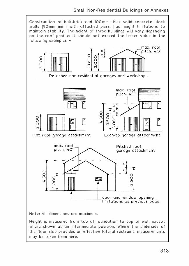
Construction of half-brick and 100mm thick solid concrete block
walls (90mm min.) with attached piers, has height limitations to
maintain stability. The height of these buildings will vary depending
on the roof profile; it should not exceed the lesser value in the
following examples ~
Note: All dimensions are maximum.
Height is measured from top of foundation to top of wall except
where shown at an intermediate position. Where the underside of
the floor slab provides an effective lateral restraint, measurements
may be taken from here.
313
Small Non-Residential Buildings or Annexes
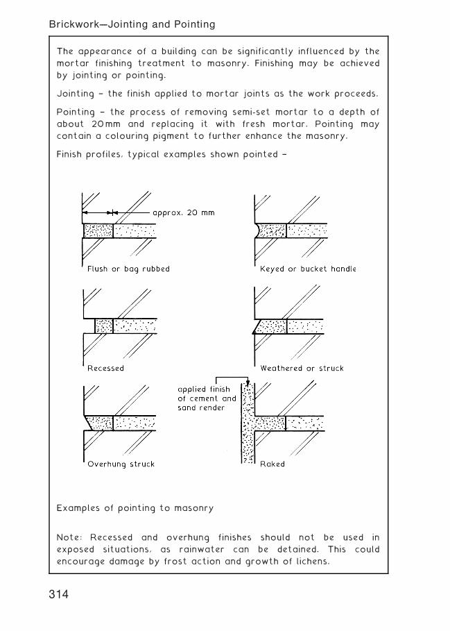
The appearance of a building can be significantly influenced by the
mortar finishing treatment to masonry. Finishing may be achieved
by jointing or pointing.
Jointing † the finish applied to mortar joints as the work proceeds.
Pointing † the process of removing semi-set mortar to a depth of
about 20mm and replacing it with fresh mortar. Pointing may
contain a colouring pigment to further enhance the masonry.
Finish profiles, typical examples shown pointed †
Examples of pointing to masonry
Note: Recessed and overhung finishes should not be used in
exposed situations, as rainwater can be detained. This could
encourage damage by frost action and growth of lichens.
314
Brickwork---Jointing and Pointing
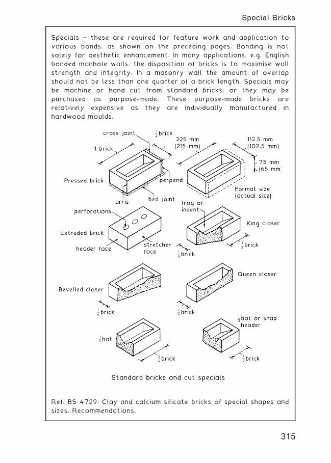
Specials † these are required for feature work and application to
various bonds, as shown on the preceding pages. Bonding is not
solely for aesthetic enhancement. In many applications, e.g. English
bonded manhole walls, the disposition of bricks is to maximise wall
strength and integrity. In a masonry wall the amount of overlap
should not be less than one quarter of a brick length. Specials may
be machine or hand cut from standard bricks, or they may be
purchased as purpose-made. These purpose-made bricks are
relatively expensive as they are individually manufactured in
hardwood moulds.
Ref. BS 4729: Clay and calcium silicate bricks of special shapes and
sizes. Recommendations.
315
Special Bricks
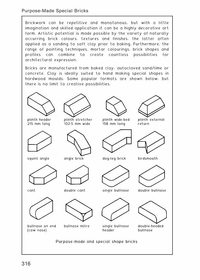
Brickwork can be repetitive and monotonous, but with a little
imagination and skilled application it can be a highly decorative art
form. Artistic potential is made possible by the variety of naturally
occurring brick colours, textures and finishes, the latter often
applied as a sanding to soft clay prior to baking. Furthermore, the
range of pointing techniques, mortar colourings, brick shapes and
profiles can combine to create countless possibilities for
architectural expression.
Bricks are manufactured from baked clay, autoclaved sand/lime or
concrete. Clay is ideally suited to hand making special shapes in
hardwood moulds. Some popular formats are shown below, but
there is no limit to creative possibilities.
316
Purpose-Made Special Bricks
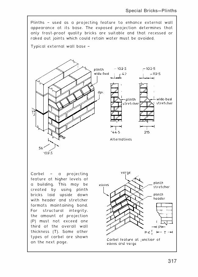
Plinths † used as a projecting feature to enhance external wall
appearance at its base. The exposed projection determines that
only frost-proof quality bricks are suitable and that recessed or
raked out joints which could retain water must be avoided.
Typical external wall base †
Corbel † a projecting
feature at higher levels of
a building. This may be
created by using plinth
bricks laid upside down
with header and stretcher
formats maintaining bond.
For structural integrity,
the amount of projection
(P) must not exceed one
third of the overall wall
thickness (T). Some other
types of corbel are shown
on the next page.
317
Special Bricks---Plinths
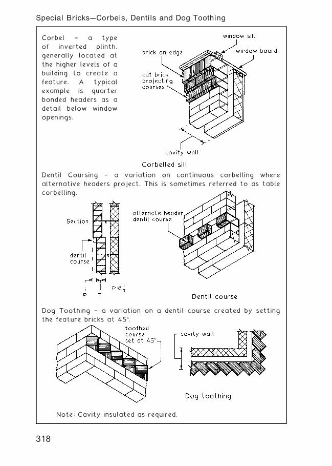
Corbel † a type
of inverted plinth,
generally located at
the higher levels of a
building to create a
feature. A typical
example is quarter
bonded headers as a
detail below window
openings.
Dentil Coursing † a variation on continuous corbelling where
alternative headers project. This is sometimes referred to as table
corbelling.
Dog Toothing † a variation on a dentil course created by setting
the feature bricks at 45�.
Note: Cavity insulated as required.
318
Special Bricks---Corbels, Dentils and Dog Toothing
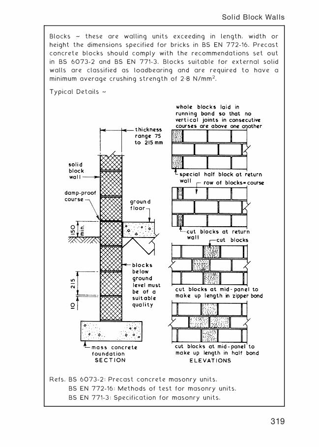
Blocks ~ these are walling units exceeding in length, width or
height the dimensions specified for bricks in BS EN 772-16. Precast
concrete blocks should comply with the recommendations set out
in BS 6073-2 and BS EN 771-3. Blocks suitable for external solid
walls are classified as loadbearing and are required to have a
minimum average crushing strength of 2„8 N/mm2.
Typical Details ~
Refs. BS 6073-2: Precast concrete masonry units.
BS EN 772-16: Methods of test for masonry units.
BS EN 771-3: Specification for masonry units.
319
Solid Block Walls
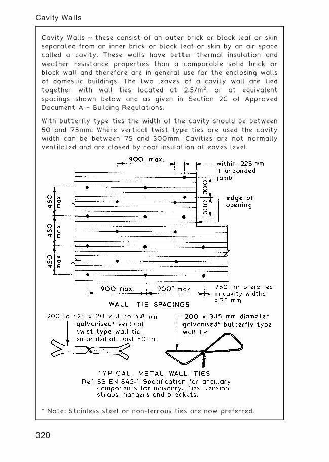
Cavity Walls ~ these consist of an outer brick or block leaf or skin
separated from an inner brick or block leaf or skin by an air space
called a cavity. These walls have better thermal insulation and
weather resistance properties than a comparable solid brick or
block wall and therefore are in general use for the enclosing walls
of domestic buildings. The two leaves of a cavity wall are tied
together with wall ties located at 2.5/m2, or at equivalent
spacings shown below and as given in Section 2C of Approved
Document A † Building Regulations.
With butterfly type ties the width of the cavity should be between
50 and 75mm. Where vertical twist type ties are used the cavity
width can be between 75 and 300mm. Cavities are not normally
ventilated and are closed by roof insulation at eaves level.
* Note: Stainless steel or non-ferrous ties are now preferred.
320
Cavity Walls
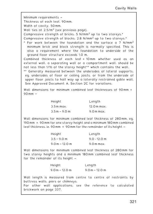
Minimum requirements ~
Thickness of each leaf, 90mm.
Width of cavity, 50mm.
Wall ties at 2.5/m2 (see previous page).
Compressive strength of bricks, 5 N/mm2 up to two storeys.*
Compressive strength of blocks, 2.8 N/mm2 up to two storeys.*
* For work between the foundation and the surface a 7 N/mm2
minimum brick and block strength is normally specified. This is
also a requirement where the foundation to underside of the
ground floor structure exceeds 1.0 m.
Combined thickness of each leaf + 10mm whether used as an
external wall, a separating wall or a compartment wall, should be
not less than 1/16 of the storey height** which contains the wall.
** Generally measured between the undersides of lateral supports,
eg. undersides of floor or ceiling joists, or from the underside of
upper floor joists to half way up a laterally restrained gable wall.
See Approved Document A, Section 2C for variations.
Wall dimensions for minimum combined leaf thicknesses of 90mm +90mm ~
Wall dimensions for minimum combined leaf thickness of 280mm, eg.
190mm + 90mm for one storey height and a minimum 180mm combined
leaf thickness, ie. 90mm + 90mm for the remainder of its height ~
Wall dimensions for minimum combined leaf thickness of 280mm for
two storey heights and a minimum 180mm combined leaf thickness
for the remainder of its height ~
Wall length is measured from centre to centre of restraints by
buttress walls, piers or chimneys.
For other wall applications, see the reference to calculated
brickwork on page 337.
Height Length
9.0m † 12.0 m 9.0m † 12.0 m
Height Length
3.5m max. 12.0m max.
3.5m † 9.0 m 9.0m max.
Height Length
3.5 † 9.0 m 9.0 - 12.0 m
9.0m † 12.0 m 9.0m max.
321
Cavity Walls
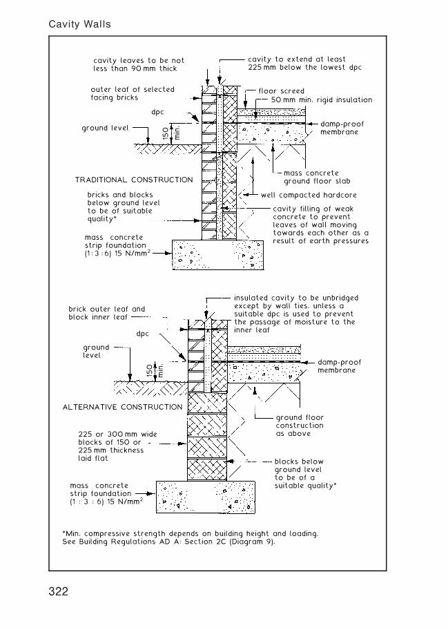
*Min. compressive strength depends on building height and loading.See Building Regulations AD A: Section 2C (Diagram 9).
cavity leaves to be notless than 90 mm thick
cavity to extend at least225 mm below the lowest dpc
outer leaf of selectedfacing bricks
dpc
ground level
TRADITIONAL CONSTRUCTION
bricks and blocksbelow ground levelto be of suitablequality*
mass concretestrip foundation(1 : 3 : 6) 15 N/mm2
cavity filling of weakconcrete to preventleaves of wall movingtowards each other as aresult of earth pressures
well compacted hardcore
mass concreteground floor slab
damp-proofmembrane
50 mm min. rigid insulationfloor screed
150
min.
brick outer leaf andblock inner leaf
dpc
150
min.
groundlevel
ALTERNATIVE CONSTRUCTION
225 or 300 mm wideblocks of 150 or225 mm thicknesslaid flat
mass concretestrip foundation(1 : 3 : 6) 15 N/mm2
blocks belowground levelto be of a suitable quality*
ground floorconstructionas above
damp-proofmembrane
insulated cavity to be unbridgedexcept by wall ties, unless asuitable dpc is used to preventthe passage of moisture to theinner leaf
322
Cavity Walls
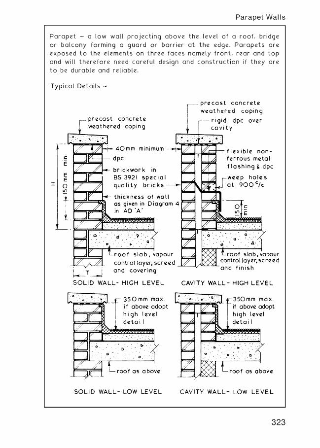
Parapet ~ a low wall projecting above the level of a roof, bridge
or balcony forming a guard or barrier at the edge. Parapets are
exposed to the elements on three faces namely front, rear and top
and will therefore need careful design and construction if they are
to be durable and reliable.
323
Parapet Walls
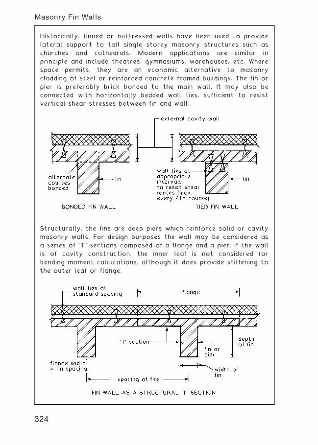
Historically, finned or buttressed walls have been used to provide
lateral support to tall single storey masonry structures such as
churches and cathedrals. Modern applications are similar in
principle and include theatres, gymnasiums, warehouses, etc. Where
space permits, they are an economic alternative to masonry
cladding of steel or reinforced concrete framed buildings. The fin or
pier is preferably brick bonded to the main wall. It may also be
connected with horizontally bedded wall ties, sufficient to resist
vertical shear stresses between fin and wall.
Structurally, the fins are deep piers which reinforce solid or cavity
masonry walls. For design purposes the wall may be considered as
a series of `T' sections composed of a flange and a pier. If the wall
is of cavity construction, the inner leaf is not considered for
bending moment calculations, although it does provide stiffening to
the outer leaf or flange.
324
Masonry Fin Walls
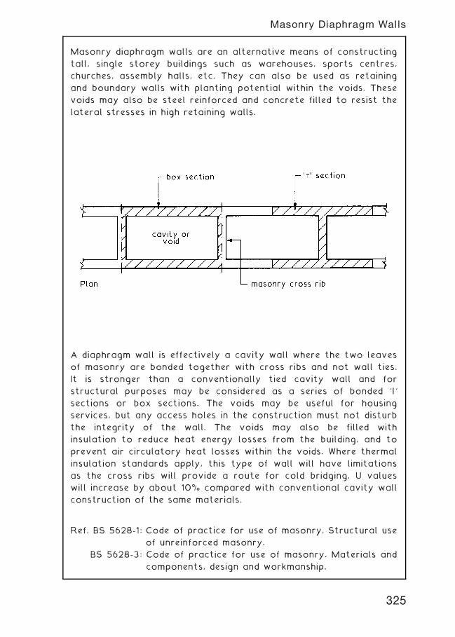
Masonry diaphragm walls are an alternative means of constructing
tall, single storey buildings such as warehouses, sports centres,
churches, assembly halls, etc. They can also be used as retaining
and boundary walls with planting potential within the voids. These
voids may also be steel reinforced and concrete filled to resist the
lateral stresses in high retaining walls.
A diaphragm wall is effectively a cavity wall where the two leaves
of masonry are bonded together with cross ribs and not wall ties.
It is stronger than a conventionally tied cavity wall and for
structural purposes may be considered as a series of bonded `I'
sections or box sections. The voids may be useful for housing
services, but any access holes in the construction must not disturb
the integrity of the wall. The voids may also be filled with
insulation to reduce heat energy losses from the building, and to
prevent air circulatory heat losses within the voids. Where thermal
insulation standards apply, this type of wall will have limitations
as the cross ribs will provide a route for cold bridging. U values
will increase by about 10% compared with conventional cavity wall
construction of the same materials.
Ref. BS 5628-1: Code of practice for use of masonry. Structural use
of unreinforced masonry.
BS 5628-3: Code of practice for use of masonry. Materials and
components, design and workmanship.
325
Masonry Diaphragm Walls
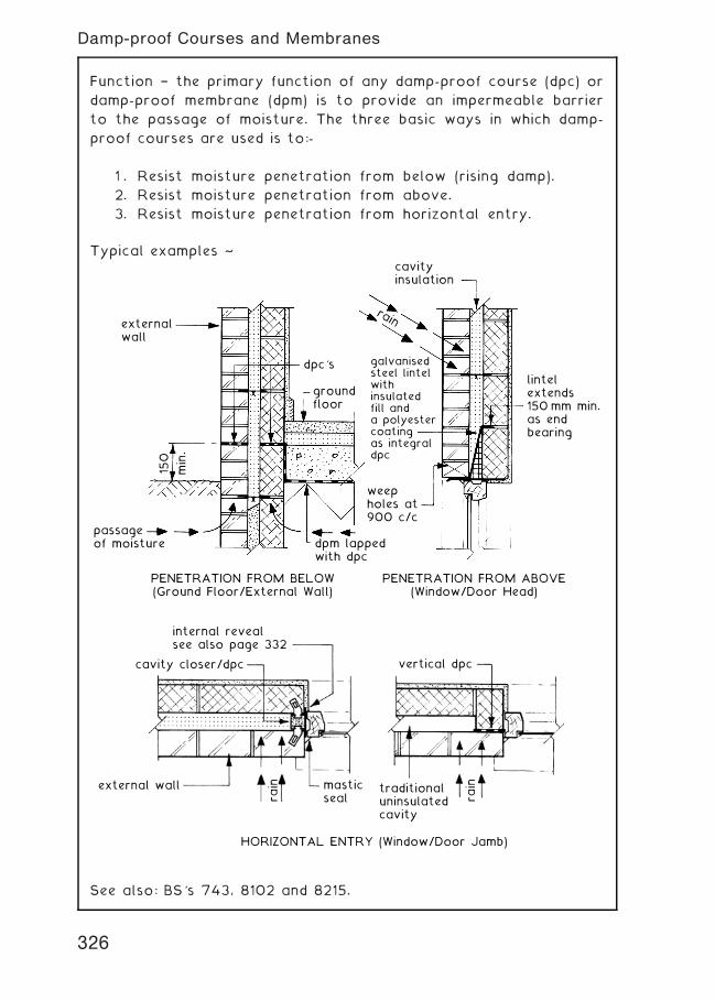
Function † the primary function of any damp-proof course (dpc) or
damp-proof membrane (dpm) is to provide an impermeable barrier
to the passage of moisture. The three basic ways in which damp-
proof courses are used is to:-
1 . Resist moisture penetration from below (rising damp).
2. Resist moisture penetration from above.
3. Resist moisture penetration from horizontal entry.
Typical examples ~
externalwall
passageof moisture dpm lapped
with dpc
weepholes at900 c/c
groundfloor
dpc's
cavityinsulation
galvanisedsteel lintelwithinsulatedfill anda polyestercoatingas integraldpc
lintelextends150 mm min.as endbearing
rain
PENETRATION FROM BELOW(Ground Floor/External Wall)
PENETRATION FROM ABOVE(Window/Door Head)
150
min.
internal revealsee also page 332
vertical dpc
traditionaluninsulatedcavity
HORIZONTAL ENTRY (Window/Door Jamb)
cavity closer/dpc
external wall masticsealra
in
rain
See also: BS's 743, 8102 and 8215.
326
Damp-proof Courses and Membranes
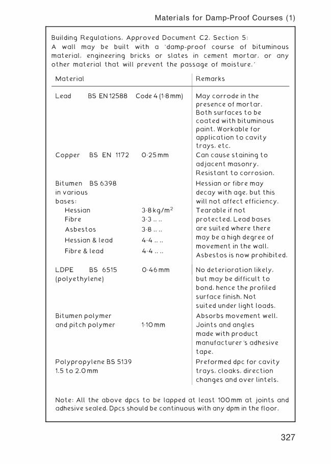
Building Regulations, Approved Document C2, Section 5:
A wall may be built with a `damp-proof course of bituminous
material, engineering bricks or slates in cement mortar, or any
other material that will prevent the passage of moisture.'
Material Remarks
Lead BS EN 12588 Code4 (1„8mm) May corrode in the
presence of mortar.
Both surfaces to be
coated with bituminous
paint. Workable for
application to cavity
trays, etc.
Copper BS EN 1172 0„25mm Can cause staining to
adjacent masonry.
Resistant to corrosion.
Bitumen BS 6398
in various
bases:
Hessian 3„8kg/m2
Fibre 3„3 .. ..
Hessian or fibre may
decay with age, but this
will not affect efficiency.
Tearable if not
protected. Lead bases
are suited where there
may be a high degree of
movement in the wall.
Asbestos is now prohibited.
Asbestos 3„8 .. ..
Hessian & lead 4„4 .. ..
Fibre & lead 4„4 .. ..
LDPE BS 6515 0„46mm
(polyethylene)
No deterioration likely,
but may be difficult to
bond, hence the profiled
surface finish. Not
suited under light loads.
Bitumen polymer
and pitch polymer 1„10mm
Absorbs movement well.
Joints and angles
made with product
manufacturer's adhesive
tape.
Polypropylene BS 5139
1.5 to 2.0mm
Preformed dpc for cavity
trays, cloaks, direction
changes and over lintels.
Note: All the above dpcs to be lapped at least 100mm at joints and
adhesive sealed. Dpcs should be continuous with any dpm in the floor.
327
Materials for Damp-Proof Courses (1)
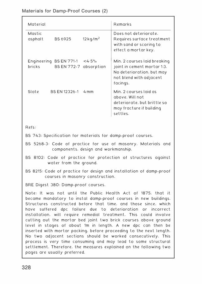
Refs:
BS 743: Specification for materials for damp-proof courses.
BS 5268-3: Code of practice for use of masonry. Materials and
components, design and workmanship.
BS 8102: Code of practice for protection of structures against
water from the ground.
BS 8215: Code of practice for design and installation of damp-proof
courses in masonry construction.
BRE Digest 380: Damp-proof courses.
Note: It was not until the Public Health Act of 1875, that it
became mandatory to instal damp-proof courses in new buildings.
Structures constructed before that time, and those since, which
have suffered dpc failure due to deterioration or incorrect
installation, will require remedial treatment. This could involve
cutting out the mortar bed joint two brick courses above ground
level in stages of about 1m in length. A new dpc can then be
inserted with mortar packing, before proceeding to the next length.
No two adjacent sections should be worked consecutively. This
process is very time consuming and may lead to some structural
settlement. Therefore, the measures explained on the following two
pages are usually preferred.
Material Remarks
Mastic
asphalt BS 6925 12kg/m2
Does not deteriorate.
Requires surface treatment
with sand or scoring to
effect a mortar key.
Engineering BS EN 771-1 <4„5%
bricks BS EN 772-7 absorption
Min. 2 courses laid breaking
joint in cement mortar 1:3.
No deterioration, but may
not blend with adjacent
facings.
Slate BS EN 12326-1 4mm Min. 2 courses laid as
above. Will not
deteriorate, but brittle so
may fracture if building
settles.
328
Materials for Damp-Proof Courses (2)
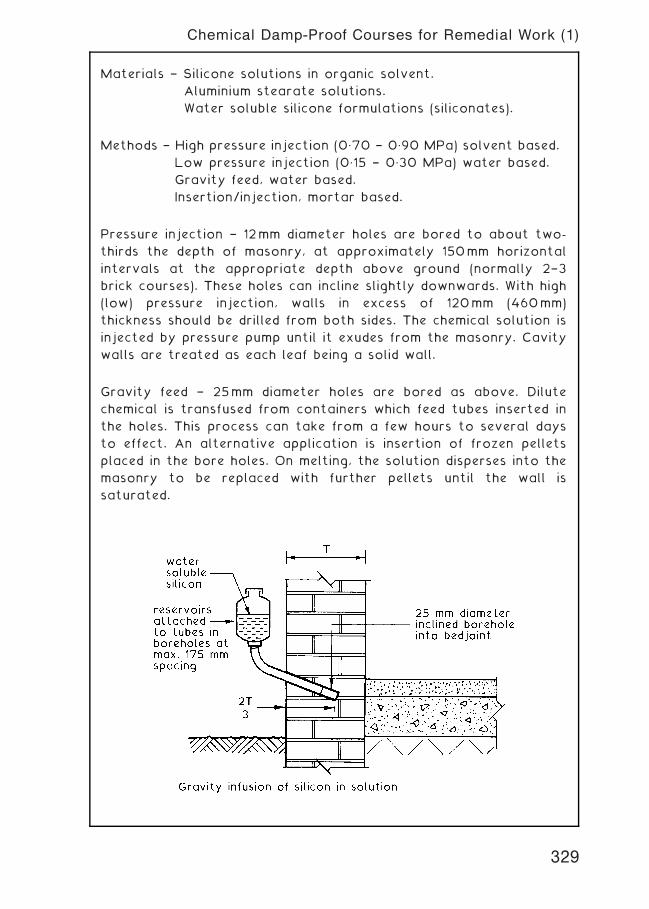
Materials † Silicone solutions in organic solvent.
Aluminium stearate solutions.
Water soluble silicone formulations (siliconates).
Methods † High pressure injection (0„70 † 0„90 MPa) solvent based.
Low pressure injection (0„15 † 0„30 MPa) water based.
Gravity feed, water based.
Insertion/injection, mortar based.
Pressure injection † 12mm diameter holes are bored to about two-
thirds the depth of masonry, at approximately 150mm horizontal
intervals at the appropriate depth above ground (normally 2†3
brick courses). These holes can incline slightly downwards. With high
(low) pressure injection, walls in excess of 120mm (460mm)
thickness should be drilled from both sides. The chemical solution is
injected by pressure pump until it exudes from the masonry. Cavity
walls are treated as each leaf being a solid wall.
Gravity feed † 25mm diameter holes are bored as above. Dilute
chemical is transfused from containers which feed tubes inserted in
the holes. This process can take from a few hours to several days
to effect. An alternative application is insertion of frozen pellets
placed in the bore holes. On melting, the solution disperses into the
masonry to be replaced with further pellets until the wall is
saturated.
329
Chemical Damp-Proof Courses for Remedial Work (1)
Injection mortars † 19mm diameter holes are bored from both sides
of a wall, at the appropriate level and no more than 230mm apart
horizontally, to a depth equating to three-fifths of the wall
thickness. They should be inclined downwards at an angle of 20 to
30�. The drill holes are flushed out with water, before injecting
mortar from the base of the hole and outwards. This can be
undertaken with a hand operated caulking gun. Special cement
mortars contain styrene butadiene resin (SDR) or epoxy resin and
must be mixed in accordance with the manufacturer's guidance.
Notes relating to all applications of chemical dpcs:
* Before commencing work, old plasterwork and rendered
undercoats are removed to expose the masonry. This should
be to a height of at least 300mm above the last detectable
(moisture meter reading) signs of rising dampness (1 metre
min.).
* If the wall is only accessible from one side and both sides
need treatment, a second deeper series of holes may be bored
from one side, to penetrate the inaccessible side.
* On completion of work, all boreholes are made good with
cement mortar. Where dilute chemicals are used for the dpc,
the mortar is rammed the full length of the hole with a piece
of timber dowelling.
* The chemicals are effective by bonding to, and lining the
masonry pores by curing and solvent evaporation.
* The process is intended to provide an acceptable measure of
control over rising dampness. A limited amount of water
vapour may still rise, but this should be dispersed by
evaporation in a heated building.
Refs.
BS 6576: Code of practice for diagnosis of rising damp in walls of
buildings and installation of chemical damp-proof courses.
BRE Digest 245: Rising damp in walls: diagnosis and treatment.
BRE Digest 380: Damp-proof courses.
BRE Good Repair Guide 6: Treating rising damp in houses.
330
Chemical Damp-Proof Courses for Remedial Work (2)
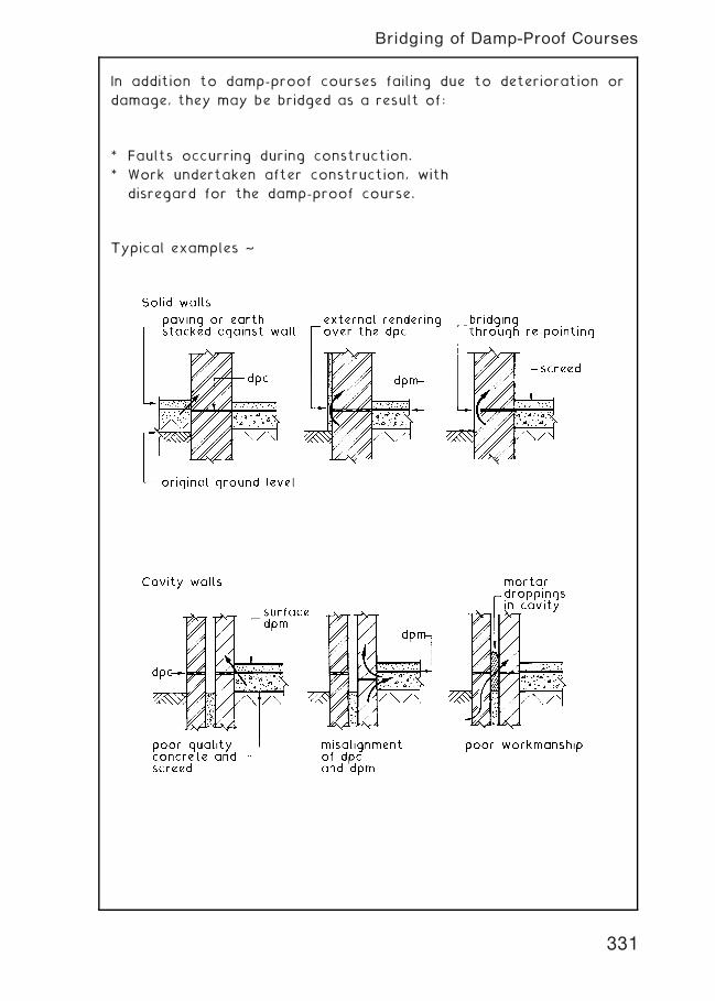
In addition to damp-proof courses failing due to deterioration or
damage, they may be bridged as a result of:
* Faults occurring during construction.
* Work undertaken after construction, with
disregard for the damp-proof course.
Typical examples ~
331
Bridging of Damp-Proof Courses
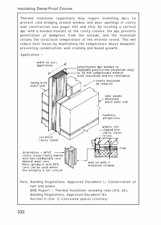
Thermal insulation regulations may require insulating dpcs to
prevent cold bridging around window and door openings in cavity
wall construction (see pages 452 and 453). By locating a vertical
dpc with a bonded insulant at the cavity closure, the dpc prevents
penetration of dampness from the outside, and the insulation
retains the structural temperature of the internal reveal. This will
reduce heat losses by maintaining the temperature above dewpoint,
preventing condensation, wall staining and mould growth.
Application †
Refs. Building Regulations, Approved Document L: Conservation of
fuel and power.
BRE Report † Thermal Insulation: avoiding risks (3rd. ed.).
Building Regulations, Approved Document B3,
Section 6 (Vol. 1): Concealed spaces (cavities).
332
Insulating Damp-Proof Course
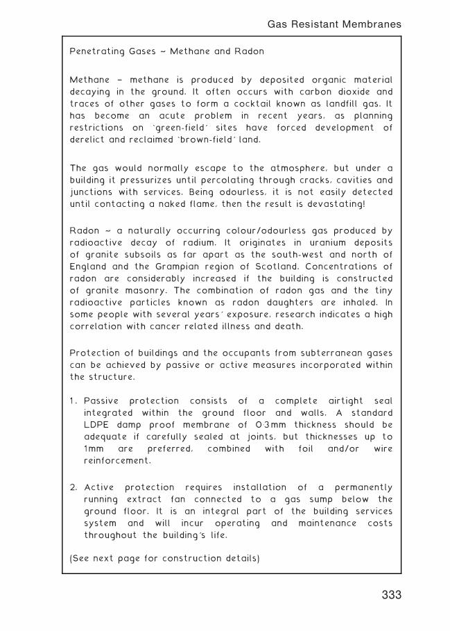
Penetrating Gases ~ Methane and Radon
Methane † methane is produced by deposited organic material
decaying in the ground. It often occurs with carbon dioxide and
traces of other gases to form a cocktail known as landfill gas. It
has become an acute problem in recent years, as planning
restrictions on `green-field' sites have forced development of
derelict and reclaimed `brown-field' land.
The gas would normally escape to the atmosphere, but under a
building it pressurizes until percolating through cracks, cavities and
junctions with services. Being odourless, it is not easily detected
until contacting a naked flame, then the result is devastating!
Radon ~ a naturally occurring colour/odourless gas produced by
radioactive decay of radium. It originates in uranium deposits
of granite subsoils as far apart as the south-west and north of
England and the Grampian region of Scotland. Concentrations of
radon are considerably increased if the building is constructed
of granite masonry. The combination of radon gas and the tiny
radioactive particles known as radon daughters are inhaled. In
some people with several years' exposure, research indicates a high
correlation with cancer related illness and death.
Protection of buildings and the occupants from subterranean gases
can be achieved by passive or active measures incorporated within
the structure.
1 . Passive protection consists of a complete airtight seal
integrated within the ground floor and walls. A standard
LDPE damp proof membrane of 0�3mm thickness should be
adequate if carefully sealed at joints, but thicknesses up to
1mm are preferred, combined with foil and/or wire
reinforcement.
2. Active protection requires installation of a permanently
running extract fan connected to a gas sump below the
ground floor. It is an integral part of the building services
system and will incur operating and maintenance costs
throughout the building's life.
(See next page for construction details)
333
Gas Resistant Membranes
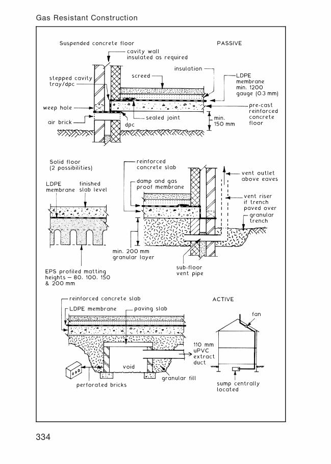
cavity wallinsulated as required
stepped cavitytray/dpc
weep hole
air brick dpc
sealed joint
screed
insulation
LDPEmembranemin. 1200gauge (0.3 mm)
PASSIVESuspended concrete floor
pre-castreinforcedconcretefloor
min.150 mm
LDPEmembrane
finishedslab level
reinforcedconcrete slab
Solid floor(2 possibilities)
damp and gasproof membrane
vent outletabove eaves
vent riserif trenchpaved over
granulartrench
sub-floorvent pipe
min. 200 mmgranular layer
EPS profiled mattingheights … 80, 100, 150& 200 mm
reinforced concrete slab ACTIVE
LDPE membrane paving slab
perforated bricksgranular fill
void
110 mmuPVCextractduct
fan
sump centrallylocated
334
Gas Resistant Construction
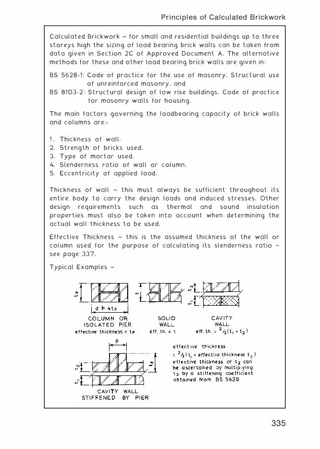
Calculated Brickwork ~ for small and residential buildings up to three
storeys high the sizing of load bearing brick walls can be taken from
data given in Section 2C of Approved Document A. The alternative
methods for these and other load bearing brick walls are given in:
BS 5628-1: Code of practice for the use of masonry. Structural use
of unreinforced masonry, and
BS 8103-2: Structural design of low rise buildings. Code of practice
for masonry walls for housing.
The main factors governing the loadbearing capacity of brick walls
and columns are:-
1 . Thickness of wall.
2. Strength of bricks used.
3. Type of mortar used.
4. Slenderness ratio of wall or column.
5. Eccentricity of applied load.
Thickness of wall ~ this must always be sufficient throughout its
entire body to carry the design loads and induced stresses. Other
design requirements such as thermal and sound insulation
properties must also be taken into account when determining the
actual wall thickness to be used.
Effective Thickness ~ this is the assumed thickness of the wall or
column used for the purpose of calculating its slenderness ratio †
see page 337.
Typical Examples ~
335
Principles of Calculated Brickwork
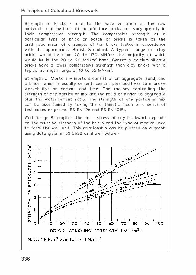
Strength of Bricks ~ due to the wide variation of the raw
materials and methods of manufacture bricks can vary greatly in
their compressive strength. The compressive strength of a
particular type of brick or batch of bricks is taken as the
arithmetic mean of a sample of ten bricks tested in accordance
with the appropriate British Standard. A typical range for clay
bricks would be from 20 to 170 MN/m2 the majority of which
would be in the 20 to 90 MN/m2 band. Generally calcium silicate
bricks have a lower compressive strength than clay bricks with a
typical strength range of 10 to 65 MN/m2.
Strength of Mortars ~ mortars consist of an aggregate (sand) and
a binder which is usually cement; cement plus additives to improve
workability; or cement and lime. The factors controlling the
strength of any particular mix are the ratio of binder to aggregate
plus the water:cement ratio. The strength of any particular mix
can be ascertained by taking the arithmetic mean of a series of
test cubes or prisms (BS EN 196 and BS EN 1015).
Wall Design Strength ~ the basic stress of any brickwork depends
on the crushing strength of the bricks and the type of mortar used
to form the wall unit. This relationship can be plotted on a graph
using data given in BS 5628 as shown below:-
336
Principles of Calculated Brickwork
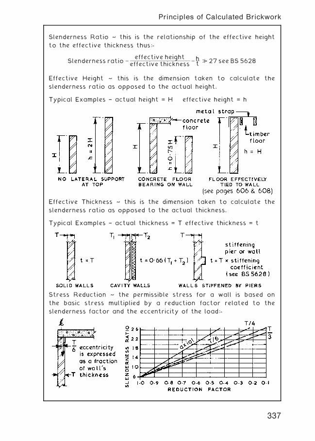
Slenderness Ratio ~ this is the relationship of the effective height
to the effective thickness thus:-
Slenderness ratio ¼effective height
effective thickness¼ ht B 27 see BS 5628
Effective Height ~ this is the dimension taken to calculate the
slenderness ratio as opposed to the actual height.
Typical Examples † actual height = H effective height = h
Effective Thickness ~ this is the dimension taken to calculate the
slenderness ratio as opposed to the actual thickness.
Typical Examples † actual thickness = T effective thickness = t
Stress Reduction ~ the permissible stress for a wall is based on
the basic stress multiplied by a reduction factor related to the
slenderness factor and the eccentricity of the load:-
337
Principles of Calculated Brickwork
Lime ~ traditional mortars are a combination of lime, sand and
water. These mixes are very workable and have sufficient flexibility
to accommodate a limited amount of wall movement due to
settlement, expansion and contraction. The long term durability of
lime mortars is poor as they can break down in the presence of
atmospheric contaminants and surface growths. Nevertheless, lime is
frequently specified as a supplementary binder with cement, to
increase mix workability and to reduce the possibility of joint
shrinkage and cracking, a characteristic of stronger cement mortars.
Cement ~ the history of cement type mortar products is extensive.
Examples dating back to the Mesopotamians and the Egyptians are
not unusual; one of the earliest examples from over 10000 years
ago has been found in Galilee, Israel. Modern mortars are made with
Portland cement, the name attributed to a bricklayer named Joseph
Aspdin. In 1824 he patented his improved hydraulic lime product as
Portland cement, as it resembled Portland stone in appearance. It was
not until the 1920s that Portland cement, as we now know it, was
first produced commercially by mixing a slurry of clay (silica, alumina
and iron-oxides) with limestone (calcium carbonate). The mix is burnt
in a furnace (calcinated) and the resulting clinker crushed and bagged.
Mortar ~ mixes for masonry should have the following properties:
* Adequate strength
* Workability
* Water retention during laying
* Plasticity during application
* Adhesion or bond
* Durability
* Good appearance ~ texture and colour
Modern mortars are a combination of cement, lime and sand plus
water. Liquid plasticisers exist as a substitute for lime, to improve
workability and to provide some resistance to frost when used
during winter.
Masonry cement ~ these proprietary cements generally contain
about 75% Portland cement and about 25% of fine limestone filler
with an air entraining plasticiser. Allowance must be made when
specifying the mortar constituents to allow for the reduced cement
content. These cements are not suitable for concrete.
Refs. BS 6463-101, 102 and 103: Quicklime, hydrated lime and
natural calcium carbonate.
BS EN 197-1: Cement. Composition, specifications and
conformity criteria for common cements.
338
Mortars for Brickwork and Blockwork (1)
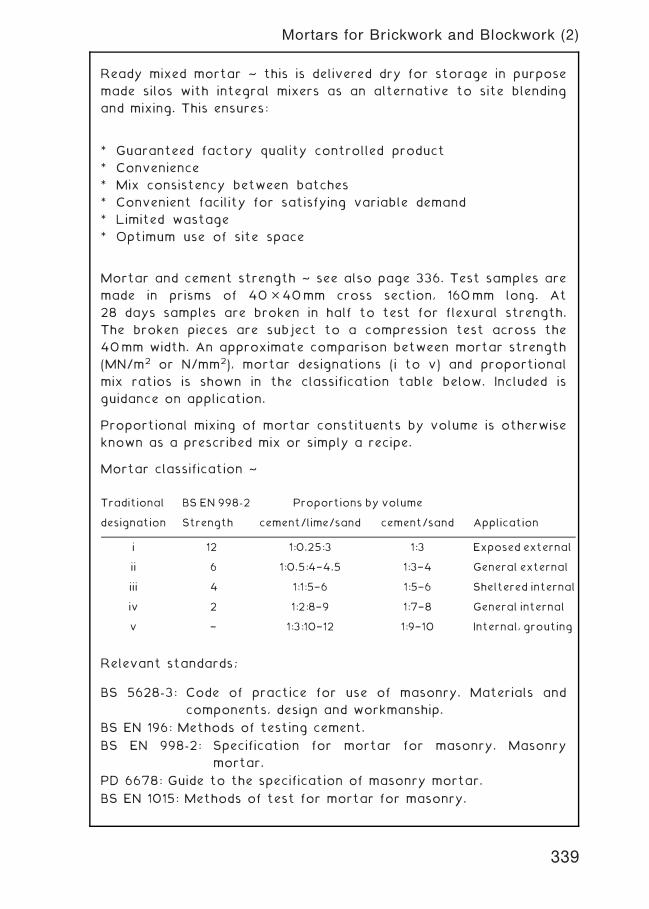
Ready mixed mortar ~ this is delivered dry for storage in purpose
made silos with integral mixers as an alternative to site blending
and mixing. This ensures:
* Guaranteed factory quality controlled product
* Convenience
* Mix consistency between batches
* Convenient facility for satisfying variable demand
* Limited wastage
* Optimum use of site space
Mortar and cement strength ~ see also page 336. Test samples are
made in prisms of 40�40mm cross section, 160mm long. At
28 days samples are broken in half to test for flexural strength.
The broken pieces are subject to a compression test across the
40mm width. An approximate comparison between mortar strength
(MN/m2 or N/mm2), mortar designations (i to v) and proportional
mix ratios is shown in the classification table below. Included is
guidance on application.
Proportional mixing of mortar constituents by volume is otherwise
known as a prescribed mix or simply a recipe.
Mortar classification ~
Relevant standards;
BS 5628-3: Code of practice for use of masonry. Materials and
components, design and workmanship.
BS EN 196: Methods of testing cement.
BS EN 998-2: Specification for mortar for masonry. Masonry
mortar.
PD 6678: Guide to the specification of masonry mortar.
BS EN 1015: Methods of test for mortar for masonry.
Traditional BS EN 998-2 Proportions by volume
designation Strength cement/lime/sand cement/sand Application
i 12 1:0.25:3 1:3 Exposed external
ii 6 1:0.5:4†4.5 1:3†4 General external
iii 4 1:1:5†6 1:5†6 Sheltered internal
iv 2 1:2:8†9 1:7†8 General internal
v † 1:3:10†12 1:9†10 Internal, grouting
339
Mortars for Brickwork and Blockwork (2)
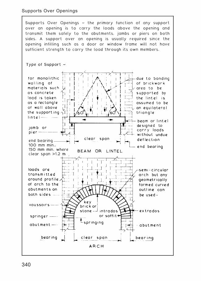
Supports Over Openings ~ the primary function of any support
over an opening is to carry the loads above the opening and
transmit them safely to the abutments, jambs or piers on both
sides. A support over an opening is usually required since the
opening infilling such as a door or window frame will not have
sufficient strength to carry the load through its own members.
340
Supports Over Openings
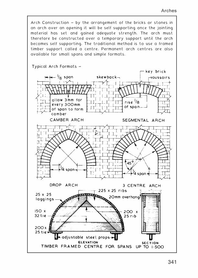
Arch Construction ~ by the arrangement of the bricks or stones in
an arch over an opening it will be self supporting once the jointing
material has set and gained adequate strength. The arch must
therefore be constructed over a temporary support until the arch
becomes self supporting. The traditional method is to use a framed
timber support called a centre. Permanent arch centres are also
available for small spans and simple formats.
341
Arches
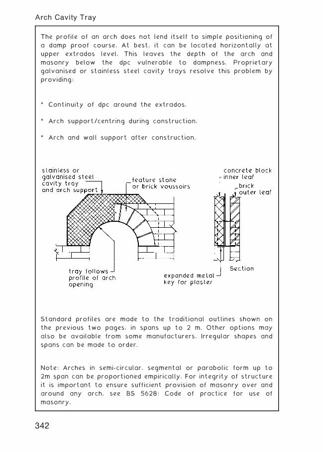
The profile of an arch does not lend itself to simple positioning of
a damp proof course. At best, it can be located horizontally at
upper extrados level. This leaves the depth of the arch and
masonry below the dpc vulnerable to dampness. Proprietary
galvanised or stainless steel cavity trays resolve this problem by
providing:
* Continuity of dpc around the extrados.
* Arch support/centring during construction.
* Arch and wall support after construction.
Standard profiles are made to the traditional outlines shown on
the previous two pages, in spans up to 2 m. Other options may
also be available from some manufacturers. Irregular shapes and
spans can be made to order.
Note: Arches in semi-circular, segmental or parabolic form up to
2m span can be proportioned empirically. For integrity of structure
it is important to ensure sufficient provision of masonry over and
around any arch, see BS 5628: Code of practice for use of
masonry.
342
Arch Cavity Tray
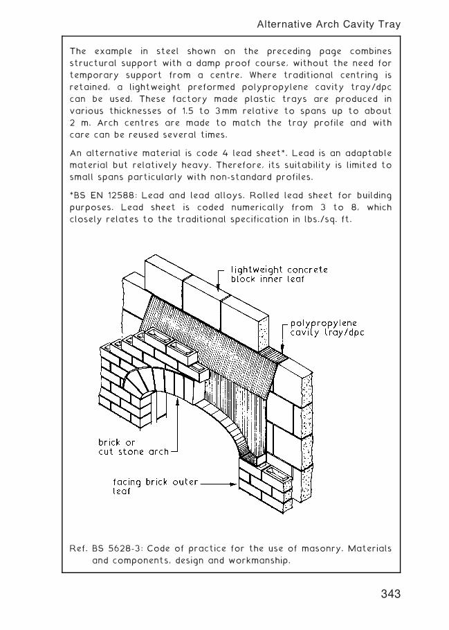
The example in steel shown on the preceding page combines
structural support with a damp proof course, without the need for
temporary support from a centre. Where traditional centring is
retained, a lightweight preformed polypropylene cavity tray/dpc
can be used. These factory made plastic trays are produced in
various thicknesses of 1.5 to 3mm relative to spans up to about
2 m. Arch centres are made to match the tray profile and with
care can be reused several times.
An alternative material is code 4 lead sheet*. Lead is an adaptable
material but relatively heavy. Therefore, its suitability is limited to
small spans particularly with non-standard profiles.
*BS EN 12588: Lead and lead alloys. Rolled lead sheet for building
purposes. Lead sheet is coded numerically from 3 to 8, which
closely relates to the traditional specification in lbs./sq. ft.
Ref. BS 5628-3: Code of practice for the use of masonry. Materials
and components, design and workmanship.
343
Alternative Arch Cavity Tray
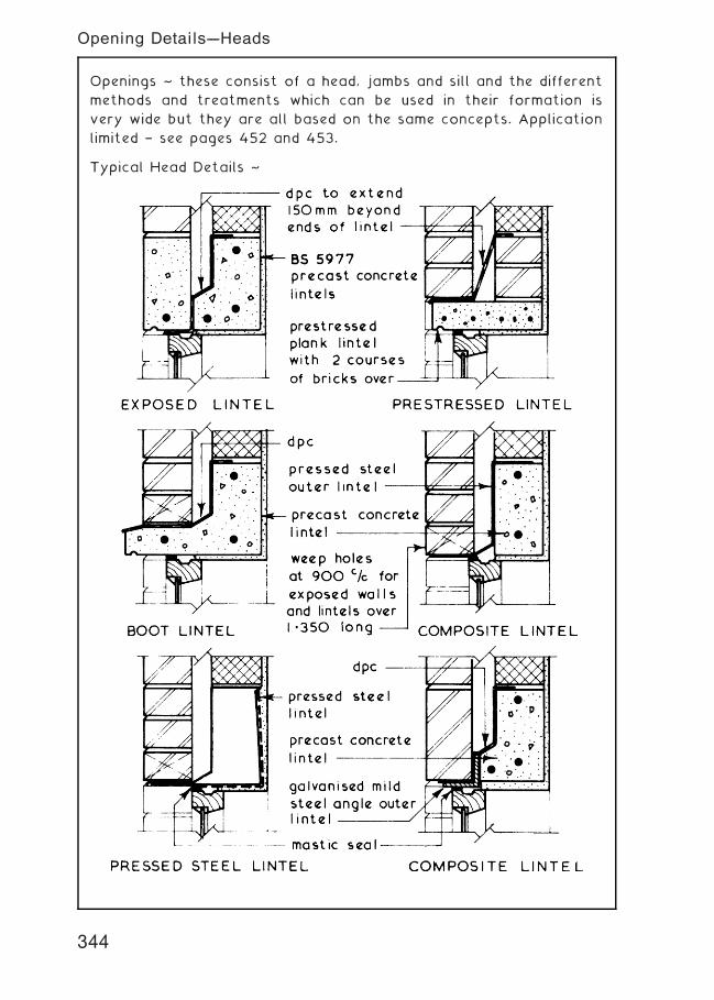
Openings ~ these consist of a head, jambs and sill and the different
methods and treatments which can be used in their formation is
very wide but they are all based on the same concepts. Application
limited † see pages 452 and 453.
Typical Head Details ~
344
Opening Details---Heads
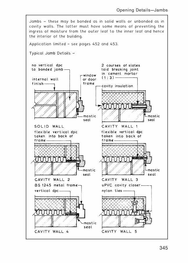
Jambs ~ these may be bonded as in solid walls or unbonded as in
cavity walls. The latter must have some means of preventing the
ingress of moisture from the outer leaf to the inner leaf and hence
the interior of the building.
Application limited † see pages 452 and 453.
345
Opening Details---Jambs
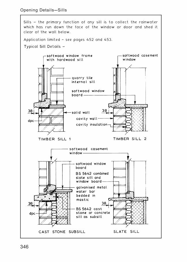
Sills ~ the primary function of any sill is to collect the rainwater
which has run down the face of the window or door and shed it
clear of the wall below.
Application limited † see pages 452 and 453.
346
Opening Details---Sills
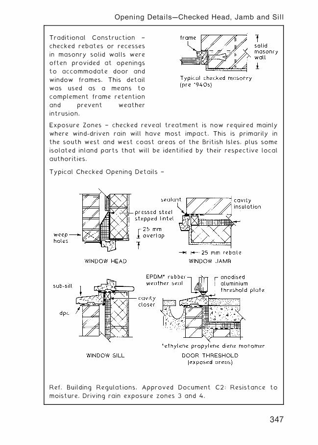
Traditional Construction †
checked rebates or recesses
in masonry solid walls were
often provided at openings
to accommodate door and
window frames. This detail
was used as a means to
complement frame retention
and prevent weather
intrusion.
Exposure Zones † checked reveal treatment is now required mainly
where wind-driven rain will have most impact. This is primarily in
the south west and west coast areas of the British Isles, plus some
isolated inland parts that will be identified by their respective local
authorities.
Typical Checked Opening Details †
Ref. Building Regulations, Approved Document C2: Resistance to
moisture. Driving rain exposure zones 3 and 4.
347
Opening Details---Checked Head, Jamb and Sill
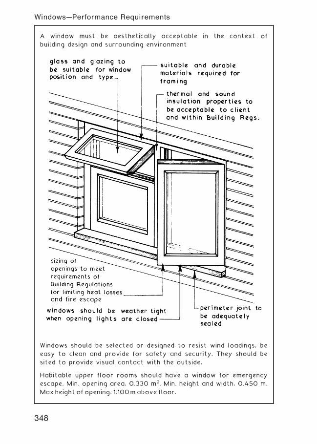
A window must be aesthetically acceptable in the context of
building design and surrounding environment
Windows should be selected or designed to resist wind loadings, be
easy to clean and provide for safety and security. They should be
sited to provide visual contact with the outside.
Habitable upper floor rooms should have a window for emergency
escape. Min. opening area, 0.330 m2. Min. height and width, 0.450 m.
Max height of opening, 1.100mabove floor.
348
Windows---Performance Requirements
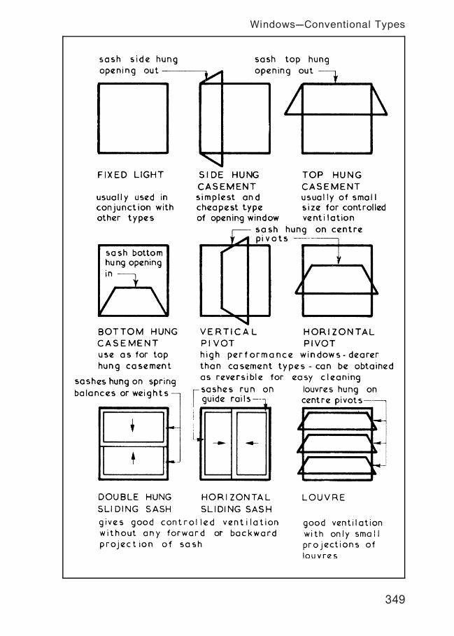
349
Windows---Conventional Types
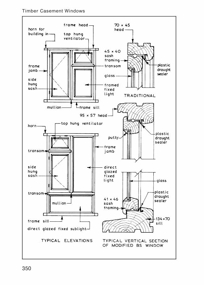
350
Timber Casement Windows
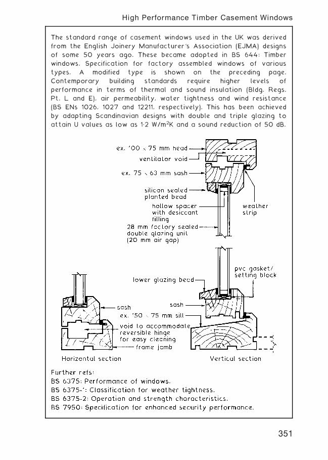
The standard range of casement windows used in the UK was derived
from the English Joinery Manufacturer's Association (EJMA) designs
of some 50 years ago. These became adopted in BS 644: Timber
windows. Specification for factory assembled windows of various
types. A modified type is shown on the preceding page.
Contemporary building standards require higher levels of
performance in terms of thermal and sound insulation (Bldg. Regs.
Pt. L and E), air permeability, water tightness and wind resistance
(BS ENs 1026, 1027 and 12211, respectively). This has been achieved
by adapting Scandinavian designs with double and triple glazing to
attain U values as low as 1„2 W/m2K and a sound reduction of 50 dB.
351
High Performance Timber Casement Windows
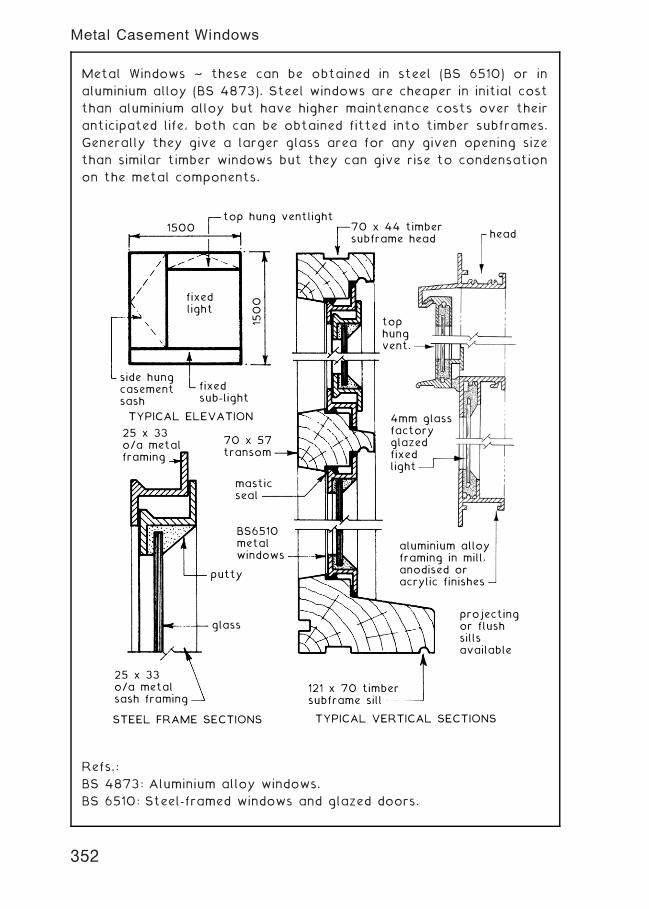
Metal Windows ~ these can be obtained in steel (BS 6510) or in
aluminium alloy (BS 4873). Steel windows are cheaper in initial cost
than aluminium alloy but have higher maintenance costs over their
anticipated life, both can be obtained fitted into timber subframes.
Generally they give a larger glass area for any given opening size
than similar timber windows but they can give rise to condensation
on the metal components.
top hung ventlight1500
1500
head70 x 44 timbersubframe head
121 x 70 timbersubframe sill
25 x 33 o/a metalsash framing
25 x 33 o/a metalframing
side hungcasementsash
fixedsub-light
70 x 57transom
glass
putty
BS6510metalwindows
masticseal
tophungvent.
4mm glassfactoryglazedfixedlight
aluminium alloyframing in mill,anodised oracrylic finishes
projectingor flushsillsavailable
TYPICAL VERTICAL SECTIONSSTEEL FRAME SECTIONS
TYPICAL ELEVATION
fixedlight
Refs.:
BS 4873: Aluminium alloy windows.
BS 6510: Steel-framed windows and glazed doors.
352
Metal Casement Windows
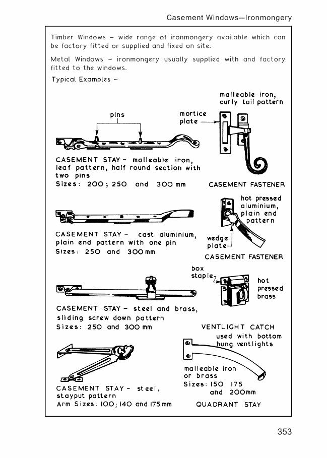
Timber Windows ~ wide range of ironmongery available which can
be factory fitted or supplied and fixed on site.
Metal Windows ~ ironmongery usually supplied with and factory
fitted to the windows.
353
Casement Windows---Ironmongery
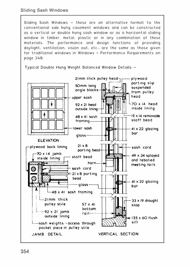
Sliding Sash Windows ~ these are an alternative format to the
conventional side hung casement windows and can be constructed
as a vertical or double hung sash window or as a horizontal sliding
window in timber, metal, plastic or in any combination of these
materials. The performance and design functions of providing
daylight, ventilation, vision out, etc., are the same as those given
for traditional windows in Windows † Performance Requirements on
page 348.
354
Sliding Sash Windows
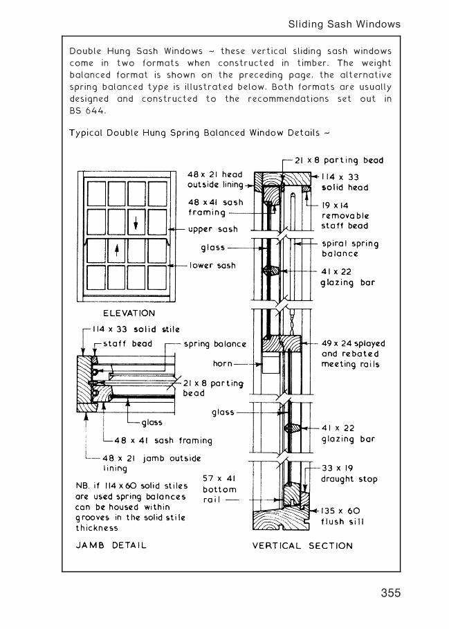
Double Hung Sash Windows ~ these vertical sliding sash windows
come in two formats when constructed in timber. The weight
balanced format is shown on the preceding page, the alternative
spring balanced type is illustrated below. Both formats are usually
designed and constructed to the recommendations set out in
BS 644.
355
Sliding Sash Windows
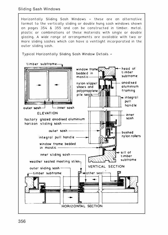
Horizontally Sliding Sash Windows ~ these are an alternative
format to the vertically sliding or double hung sash windows shown
on pages 354 & 355 and can be constructed in timber, metal,
plastic or combinations of these materials with single or double
glazing. A wide range of arrangements are available with two or
more sliding sashes which can have a ventlight incorporated in the
outer sliding sash.
356
Sliding Sash Windows
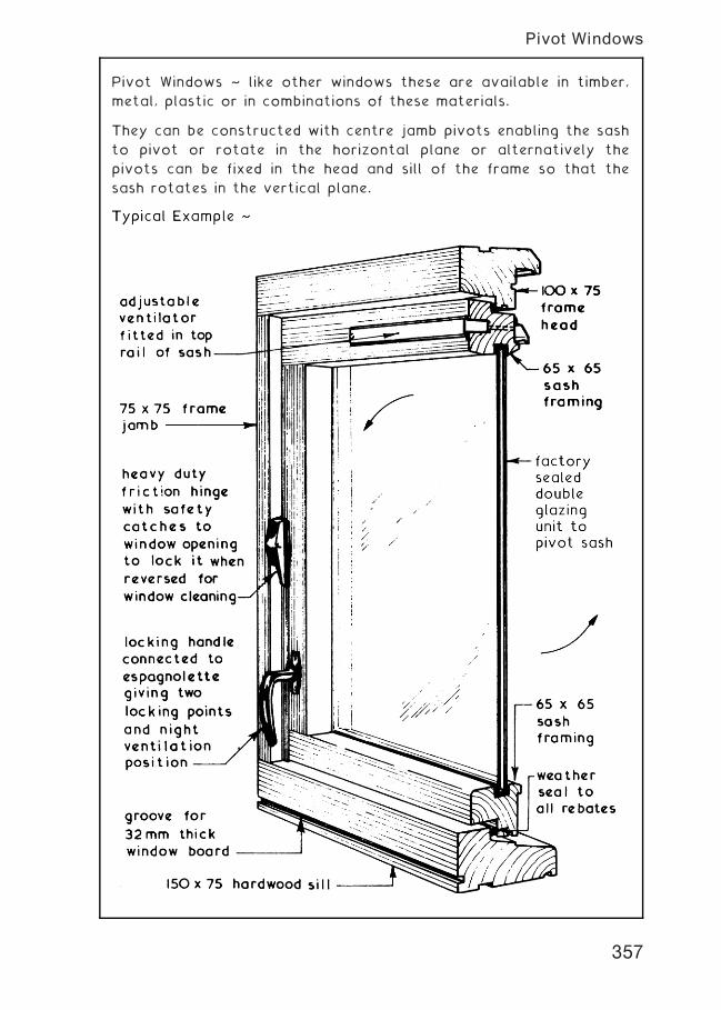
Pivot Windows ~ like other windows these are available in timber,
metal, plastic or in combinations of these materials.
They can be constructed with centre jamb pivots enabling the sash
to pivot or rotate in the horizontal plane or alternatively the
pivots can be fixed in the head and sill of the frame so that the
sash rotates in the vertical plane.
357
Pivot Windows
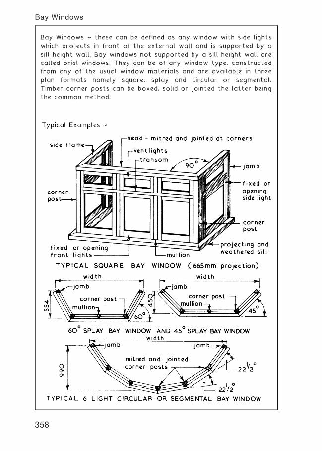
Bay Windows ~ these can be defined as any window with side lights
which projects in front of the external wall and is supported by a
sill height wall. Bay windows not supported by a sill height wall are
called oriel windows. They can be of any window type, constructed
from any of the usual window materials and are available in three
plan formats namely square, splay and circular or segmental.
Timber corner posts can be boxed, solid or jointed the latter being
the common method.
358
Bay Windows
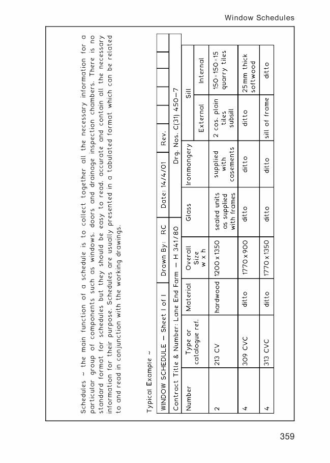
Schedules
~the
main
functio
nof
aschedule
isto
collect
together
all
the
necessary
info
rmatio
nfo
ra
part
icula
rgro
up
of
components
such
as
windows,doors
and
dra
inage
inspectio
nchambers
.There
isno
standard
form
at
for
schedules
but
they
should
be
easy
to
read,accura
te
and
contain
all
the
necessary
info
rmatio
nfo
rtheir
purp
ose.Schedules
are
usually
pre
sented
ina
tabula
ted
form
at
which
can
be
rela
ted
to
and
read
inconju
nctio
nwith
the
work
ing
dra
wings.
359
Window Schedules
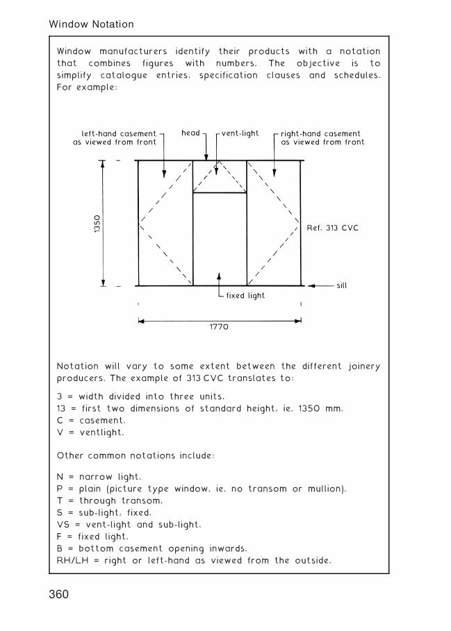
Window manufacturers identify their products with a notation
that combines figures with numbers. The objective is to
simplify catalogue entries, specification clauses and schedules.
For example:
head
1350
1770
fixed light
sill
vent-lightleft-hand casementas viewed from front
right-hand casementas viewed from front
Ref. 313 CVC
Notation will vary to some extent between the different joinery
producers. The example of 313 CVC translates to:
3 = width divided into three units.
13 = first two dimensions of standard height, ie. 1350 mm.
C = casement.
V = ventlight.
Other common notations include:
N = narrow light.
P = plain (picture type window, ie. no transom or mullion).
T = through transom.
S = sub-light, fixed.
VS = vent-light and sub-light.
F = fixed light.
B = bottom casement opening inwards.
RH/LH = right or left-hand as viewed from the outside.
360
Window Notation
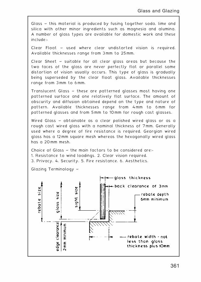
Glass ~ this material is produced by fusing together soda, lime and
silica with other minor ingredients such as magnesia and alumina.
A number of glass types are available for domestic work and these
include:-
Clear Float ~ used where clear undistorted vision is required.
Available thicknesses range from 3mm to 25mm.
Clear Sheet ~ suitable for all clear glass areas but because the
two faces of the glass are never perfectly flat or parallel some
distortion of vision usually occurs. This type of glass is gradually
being superseded by the clear float glass. Available thicknesses
range from 3mm to 6mm.
Translucent Glass ~ these are patterned glasses most having one
patterned surface and one relatively flat surface. The amount of
obscurity and diffusion obtained depend on the type and nature of
pattern. Available thicknesses range from 4mm to 6mm for
patterned glasses and from 5mm to 10mm for rough cast glasses.
Wired Glass ~ obtainable as a clear polished wired glass or as a
rough cast wired glass with a nominal thickness of 7mm. Generally
used where a degree of fire resistance is required. Georgian wired
glass has a 12mm square mesh whereas the hexagonally wired glass
has a 20mm mesh.
Choice of Glass ~ the main factors to be considered are:-
1. Resistance to wind loadings. 2. Clear vision required.
3. Privacy. 4. Security. 5. Fire resistance. 6. Aesthetics.
Glazing Terminology ~
361
Glass and Glazing
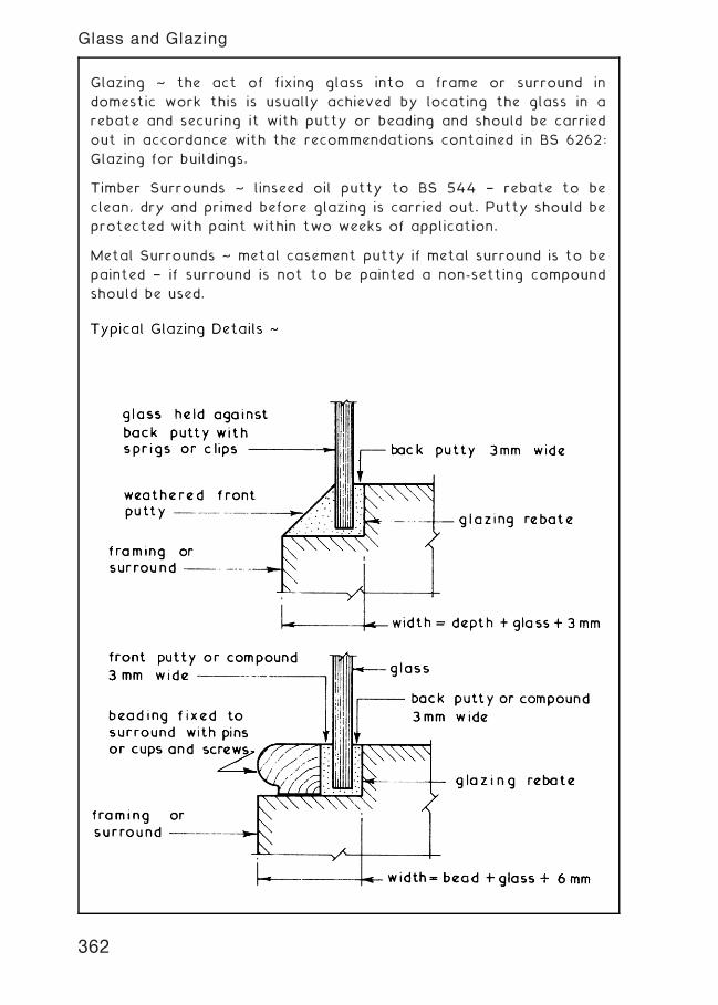
Glazing ~ the act of fixing glass into a frame or surround in
domestic work this is usually achieved by locating the glass in a
rebate and securing it with putty or beading and should be carried
out in accordance with the recommendations contained in BS 6262:
Glazing for buildings.
Timber Surrounds ~ linseed oil putty to BS 544 † rebate to be
clean, dry and primed before glazing is carried out. Putty should be
protected with paint within two weeks of application.
Metal Surrounds ~ metal casement putty if metal surround is to be
painted † if surround is not to be painted a non-setting compound
should be used.
362
Glass and Glazing
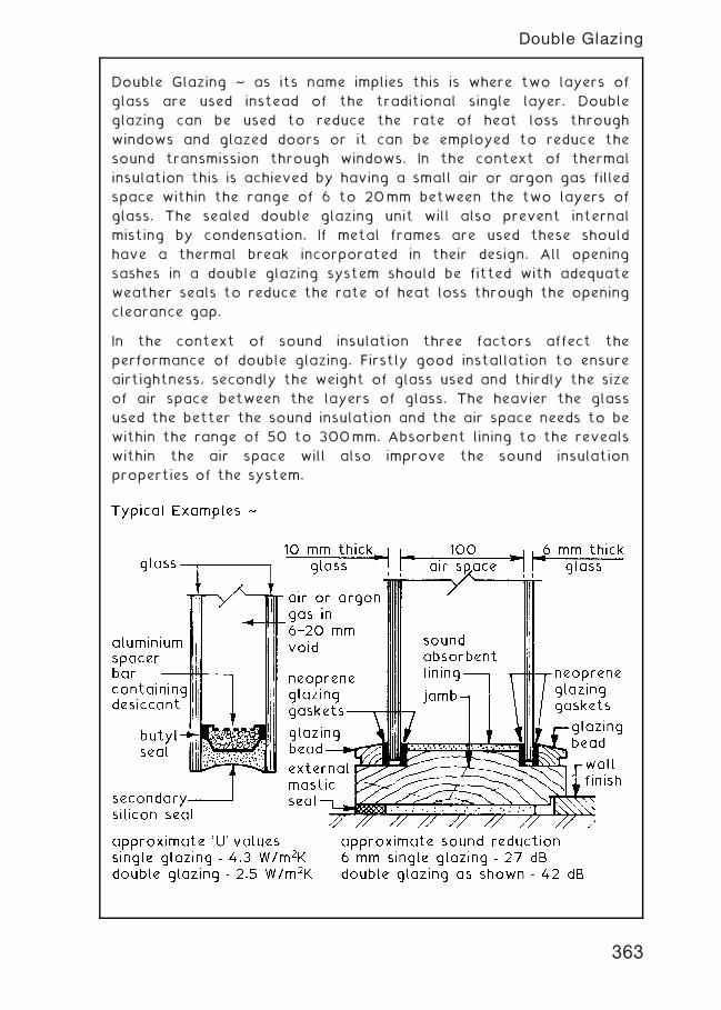
Double Glazing ~ as its name implies this is where two layers of
glass are used instead of the traditional single layer. Double
glazing can be used to reduce the rate of heat loss through
windows and glazed doors or it can be employed to reduce the
sound transmission through windows. In the context of thermal
insulation this is achieved by having a small air or argon gas filled
space within the range of 6 to 20mm between the two layers of
glass. The sealed double glazing unit will also prevent internal
misting by condensation. If metal frames are used these should
have a thermal break incorporated in their design. All opening
sashes in a double glazing system should be fitted with adequate
weather seals to reduce the rate of heat loss through the opening
clearance gap.
In the context of sound insulation three factors affect the
performance of double glazing. Firstly good installation to ensure
airtightness, secondly the weight of glass used and thirdly the size
of air space between the layers of glass. The heavier the glass
used the better the sound insulation and the air space needs to be
within the range of 50 to 300mm. Absorbent lining to the reveals
within the air space will also improve the sound insulation
properties of the system.
363
Double Glazing
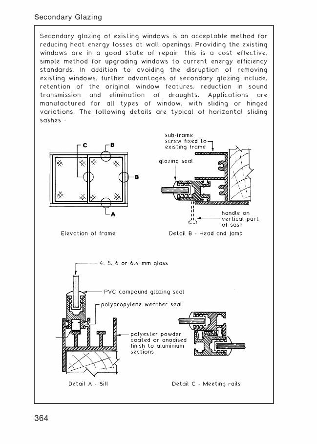
Secondary glazing of existing windows is an acceptable method for
reducing heat energy losses at wall openings. Providing the existing
windows are in a good state of repair, this is a cost effective,
simple method for upgrading windows to current energy efficiency
standards. In addition to avoiding the disruption of removing
existing windows, further advantages of secondary glazing include,
retention of the original window features, reduction in sound
transmission and elimination of draughts. Applications are
manufactured for all types of window, with sliding or hinged
variations. The following details are typical of horizontal sliding
sashes -
364
Secondary Glazing
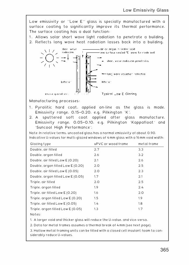
Low emissivity or ``Low E'' glass is specially manufactured with a
surface coating to significantly improve its thermal performance.
The surface coating has a dual function:
1 . Allows solar short wave light radiation to penetrate a building.
2. Reflects long wave heat radiation losses back into a building.
Manufacturing processes:
1 . Pyrolitic hard coat, applied on-line as the glass is made.
Emissivity range, 0.15†0.20, e.g. Pilkington `K'.
2. A sputtered soft coat applied after glass manufacture.
Emissivity range, 0.05†0.10, e.g. Pilkington `Kappafloat' and
`Suncool High Performance'.
Note: In relative terms, uncoated glass has a normal emissivity of about 0.90.
Indicative U-values for multi-glazed windows of 4mm glass with a 16mm void width:
Glazing type uPVC or wood frame metal frame
Double, air filled 2.7 3.3
Double, argon filled 2.6 3.2
Double, air filled Low E (0.20) 2.1 2.6
Double, argon filled Low E (0.20) 2.0 2.5
Double, air filled Low E (0.05) 2.0 2.3
Double, argon filled Low E (0.05) 1.7 2.1
Triple, air filled 2.0 2.5
Triple, argon filled 1.9 2.4
Triple, air filled Low E (0.20) 1.6 2.0
Triple, argon filled Low E (0.20) 1.5 1.9
Triple, air filled Low E (0.05) 1.4 1.8
Triple, argon filled Low E (0.05) 1.3 1.7
Notes:
1. A larger void and thicker glass will reduce the U-value, and vice-versa.
2. Data for metal frames assumes a thermal break of 4mm (see next page).
3. Hollowmetal framing units can be filled with a closed cell insulant foam to con-
siderably reduce U-values.
365
Low Emissivity Glass
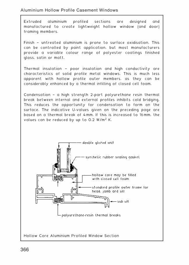
Extruded aluminium profiled sections are designed and
manufactured to create lightweight hollow window (and door)
framing members.
Finish † untreated aluminium is prone to surface oxidisation. This
can be controlled by paint application, but most manufacturers
provide a variable colour range of polyester coatings finished
gloss, satin or matt.
Thermal insulation † poor insulation and high conductivity are
characteristics of solid profile metal windows. This is much less
apparent with hollow profile outer members, as they can be
considerably enhanced by a thermal infilling of closed cell foam.
Condensation † a high strength 2-part polyurethane resin thermal
break between internal and external profiles inhibits cold bridging.
This reduces the opportunity for condensation to form on the
surface. The indicative U-values given on the preceding page are
based on a thermal break of 4mm. If this is increased to 16mm, the
values can be reduced by up to 0.2 W/m2 K.
Hollow Core Aluminium Profiled Window Section
366
Aluminium Hollow Profile Casement Windows
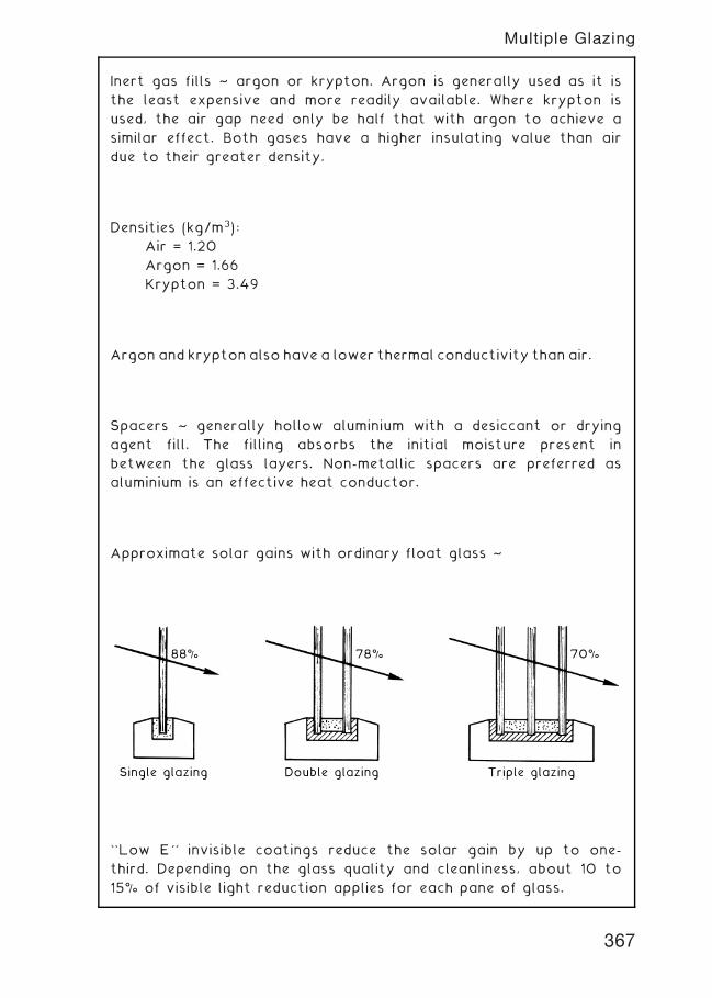
Inert gas fills ~ argon or krypton. Argon is generally used as it is
the least expensive and more readily available. Where krypton is
used, the air gap need only be half that with argon to achieve a
similar effect. Both gases have a higher insulating value than air
due to their greater density.
Densities (kg/m3):
Air = 1.20
Argon = 1.66
Krypton = 3.49
Argon and krypton also have a lower thermal conductivity than air.
Spacers ~ generally hollow aluminium with a desiccant or drying
agent fill. The filling absorbs the initial moisture present in
between the glass layers. Non-metallic spacers are preferred as
aluminium is an effective heat conductor.
Approximate solar gains with ordinary float glass ~
Single glazing
88% 78% 70%
Double glazing Triple glazing
``Low E'' invisible coatings reduce the solar gain by up to one-
third. Depending on the glass quality and cleanliness, about 10 to
15% of visible light reduction applies for each pane of glass.
367
Multiple Glazing
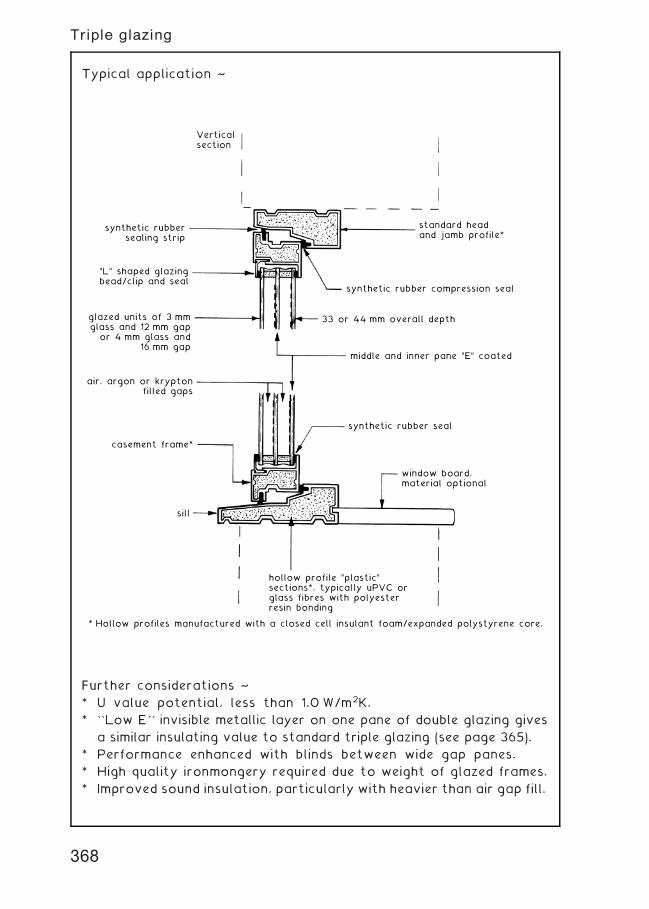
Typical application ~
* Hollow profiles manufactured with a closed cell insulant foam/expanded polystyrene core.
Verticalsection
synthetic rubbersealing strip
"L" shaped glazingbead/clip and seal
glazed units of 3 mmglass and 12 mm gap
or 4 mm glass and16 mm gap
air, argon or kryptonfilled gaps
casement frame*
window board,material optional
synthetic rubber seal
middle and inner pane "E" coated
33 or 44 mm overall depth
synthetic rubber compression seal
standard head and jamb profile*
hollow profile "plastic"sections*, typically uPVC orglass fibres with polyesterresin bonding
sill
Further considerations ~
* U value potential, less than 1.0 W/m2K.
* ``Low E'' invisible metallic layer on one pane of double glazing gives
a similar insulating value to standard triple glazing (see page 365).
* Performance enhanced with blinds between wide gap panes.
* High quality ironmongery required due to weight of glazed frames.
* Improved sound insulation, particularly with heavier than air gap fill.
368
Triple glazing
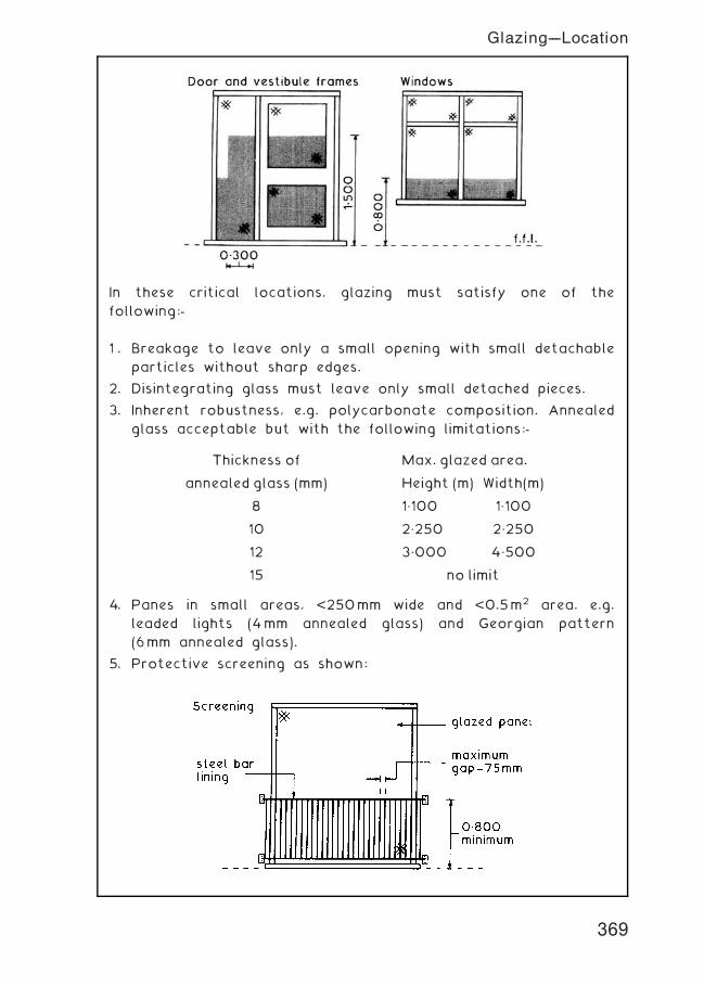
In these critical locations, glazing must satisfy one of the
following:-
1 . Breakage to leave only a small opening with small detachable
particles without sharp edges.
2. Disintegrating glass must leave only small detached pieces.
3. Inherent robustness, e.g. polycarbonate composition. Annealed
glass acceptable but with the following limitations:-
4. Panes in small areas, <250mm wide and <0.5m2 area. e.g.
leaded lights (4mm annealed glass) and Georgian pattern
(6mm annealed glass).
5. Protective screening as shown:
Thickness of Max. glazed area.
annealed glass (mm) Height (m) Width(m)
8 1„100 1„100
10 2„250 2„250
12 3„000 4„500
15 no limit
369
Glazing---Location
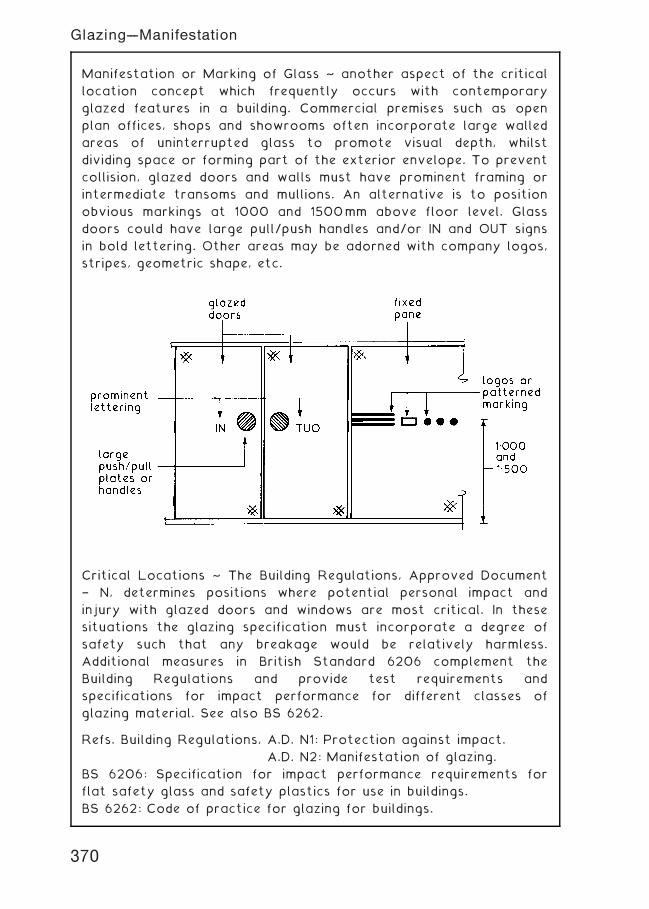
Manifestation or Marking of Glass ~ another aspect of the critical
location concept which frequently occurs with contemporary
glazed features in a building. Commercial premises such as open
plan offices, shops and showrooms often incorporate large walled
areas of uninterrupted glass to promote visual depth, whilst
dividing space or forming part of the exterior envelope. To prevent
collision, glazed doors and walls must have prominent framing or
intermediate transoms and mullions. An alternative is to position
obvious markings at 1000 and 1500mm above floor level. Glass
doors could have large pull/push handles and/or IN and OUT signs
in bold lettering. Other areas may be adorned with company logos,
stripes, geometric shape, etc.
Critical Locations ~ The Building Regulations, Approved Document
† N, determines positions where potential personal impact and
injury with glazed doors and windows are most critical. In these
situations the glazing specification must incorporate a degree of
safety such that any breakage would be relatively harmless.
Additional measures in British Standard 6206 complement the
Building Regulations and provide test requirements and
specifications for impact performance for different classes of
glazing material. See also BS 6262.
Refs. Building Regulations, A.D. N1: Protection against impact.
A.D. N2: Manifestation of glazing.
BS 6206: Specification for impact performance requirements for
flat safety glass and safety plastics for use in buildings.
BS 6262: Code of practice for glazing for buildings.
370
Glazing---Manifestation
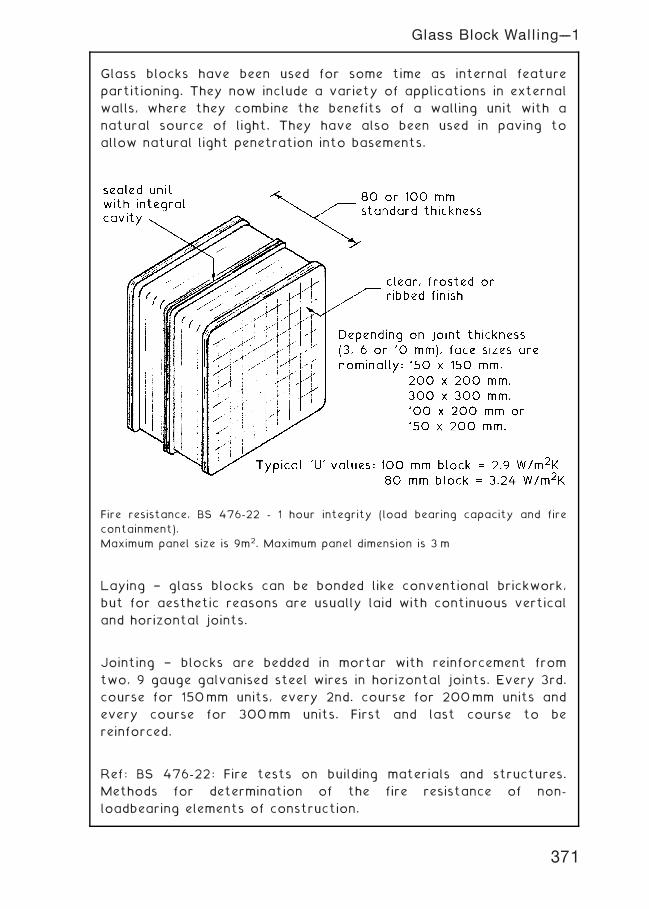
Glass blocks have been used for some time as internal feature
partitioning. They now include a variety of applications in external
walls, where they combine the benefits of a walling unit with a
natural source of light. They have also been used in paving to
allow natural light penetration into basements.
Fire resistance, BS 476-22 - 1 hour integrity (load bearing capacity and fire
containment).
Maximum panel size is 9m2. Maximum panel dimension is 3 m
Laying † glass blocks can be bonded like conventional brickwork,
but for aesthetic reasons are usually laid with continuous vertical
and horizontal joints.
Jointing † blocks are bedded in mortar with reinforcement from
two, 9 gauge galvanised steel wires in horizontal joints. Every 3rd.
course for 150mm units, every 2nd. course for 200mm units and
every course for 300mm units. First and last course to be
reinforced.
Ref: BS 476-22: Fire tests on building materials and structures.
Methods for determination of the fire resistance of non-
loadbearing elements of construction.
371
Glass Block Walling---1
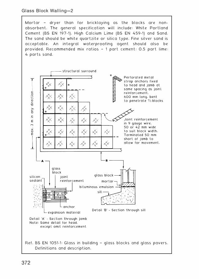
Mortar † dryer than for bricklaying as the blocks are non-
absorbent. The general specification will include: White Portland
Cement (BS EN 197-1), High Calcium Lime (BS EN 459-1) and Sand.
The sand should be white quartzite or silica type. Fine silver sand is
acceptable. An integral waterproofing agent should also be
provided. Recommended mix ratios † 1 part cement: 0.5 part lime:
4 parts sand.
Ref. BS EN 1051-1: Glass in building † glass blocks and glass pavers.
Definitions and description.
372
Glass Block Walling---2
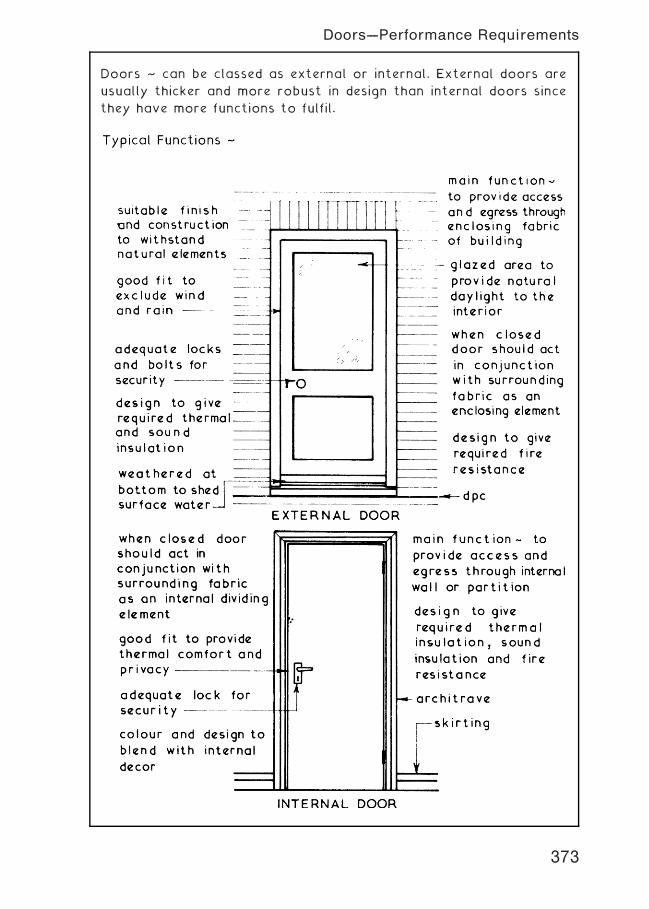
Doors ~ can be classed as external or internal. External doors are
usually thicker and more robust in design than internal doors since
they have more functions to fulfil.
373
Doors---Performance Requirements
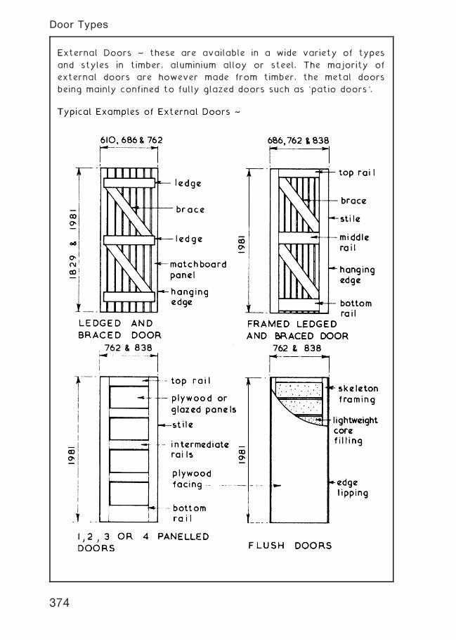
External Doors ~ these are available in a wide variety of types
and styles in timber, aluminium alloy or steel. The majority of
external doors are however made from timber, the metal doors
being mainly confined to fully glazed doors such as `patio doors'.
374
Door Types
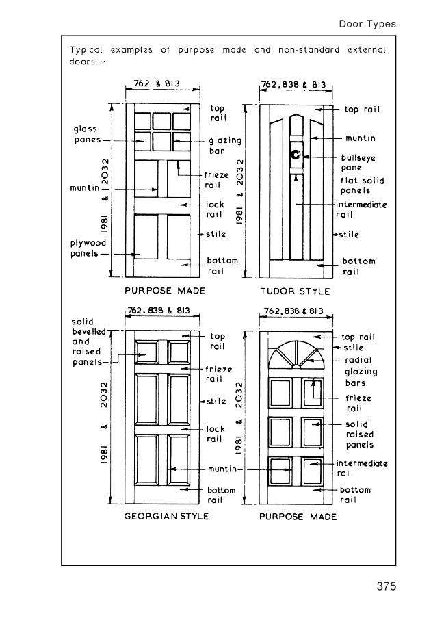
375
Door Types
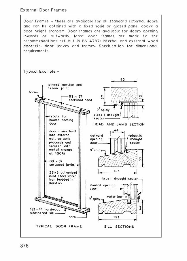
Door Frames ~ these are available for all standard external doors
and can be obtained with a fixed solid or glazed panel above a
door height transom. Door frames are available for doors opening
inwards or outwards. Most door frames are made to the
recommendations set out in BS 4787: Internal and external wood
doorsets, door leaves and frames. Specification for dimensional
requirements.
376
External Door Frames
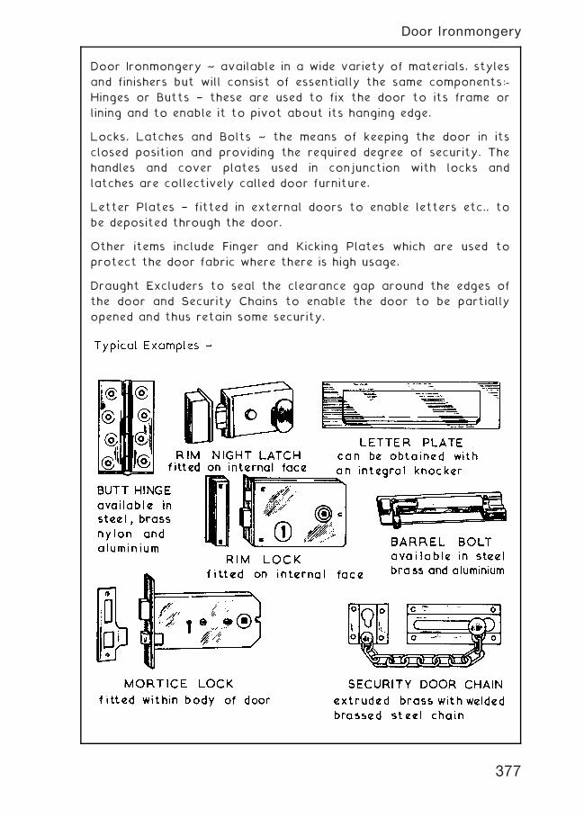
Door Ironmongery ~ available in a wide variety of materials, styles
and finishers but will consist of essentially the same components:-
Hinges or Butts † these are used to fix the door to its frame or
lining and to enable it to pivot about its hanging edge.
Locks, Latches and Bolts ~ the means of keeping the door in its
closed position and providing the required degree of security. The
handles and cover plates used in conjunction with locks and
latches are collectively called door furniture.
Letter Plates † fitted in external doors to enable letters etc., to
be deposited through the door.
Other items include Finger and Kicking Plates which are used to
protect the door fabric where there is high usage,
Draught Excluders to seal the clearance gap around the edges of
the door and Security Chains to enable the door to be partially
opened and thus retain some security.
377
Door Ironmongery
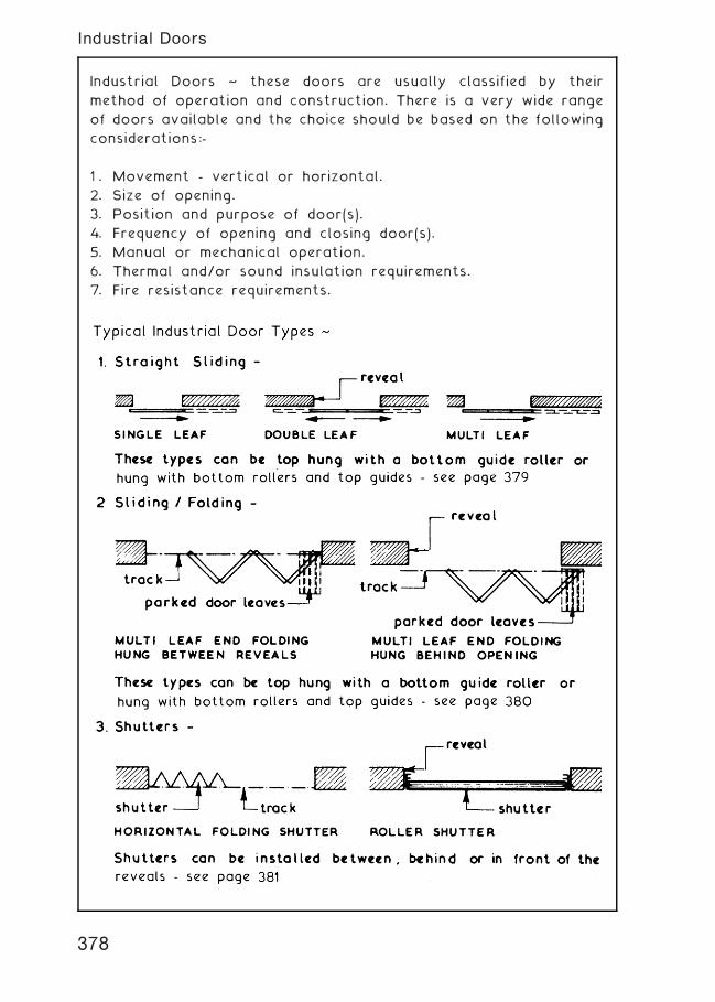
Industrial Doors ~ these doors are usually classified by their
method of operation and construction. There is a very wide range
of doors available and the choice should be based on the following
considerations:-
1 . Movement - vertical or horizontal.
2. Size of opening.
3. Position and purpose of door(s).
4. Frequency of opening and closing door(s).
5. Manual or mechanical operation.
6. Thermal and/or sound insulation requirements.
7. Fire resistance requirements.
378
Industrial Doors
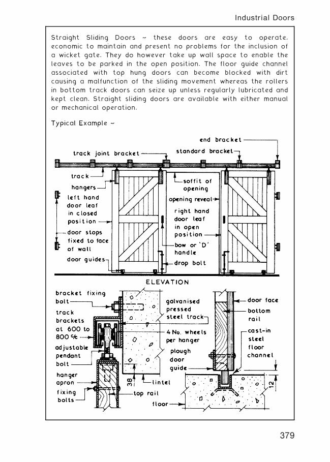
Straight Sliding Doors ~ these doors are easy to operate,
economic to maintain and present no problems for the inclusion of
a wicket gate. They do however take up wall space to enable the
leaves to be parked in the open position. The floor guide channel
associated with top hung doors can become blocked with dirt
causing a malfunction of the sliding movement whereas the rollers
in bottom track doors can seize up unless regularly lubricated and
kept clean. Straight sliding doors are available with either manual
or mechanical operation.
379
Industrial Doors
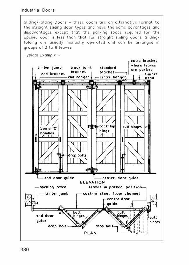
Sliding/Folding Doors ~ these doors are an alternative format to
the straight sliding door types and have the same advantages and
disadvantages except that the parking space required for the
opened door is less than that for straight sliding doors. Sliding/
folding are usually manually operated and can be arranged in
groups of 2 to 8 leaves.
Typical Example ~
380
Industrial Doors
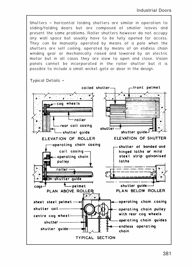
Shutters ~ horizontal folding shutters are similar in operation to
sliding/folding doors but are composed of smaller leaves and
present the same problems. Roller shutters however do not occupy
any wall space but usually have to be fully opened for access.
They can be manually operated by means of a pole when the
shutters are self coiling, operated by means of an endless chain
winding gear or mechanically raised and lowered by an electric
motor but in all cases they are slow to open and close. Vision
panels cannot be incorporated in the roller shutter but it is
possible to include a small wicket gate or door in the design.
381
Industrial Doors
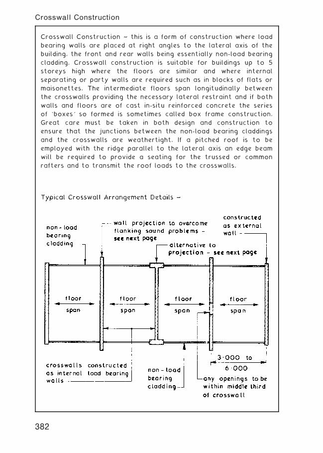
Crosswall Construction ~ this is a form of construction where load
bearing walls are placed at right angles to the lateral axis of the
building, the front and rear walls being essentially non-load bearing
cladding. Crosswall construction is suitable for buildings up to 5
storeys high where the floors are similar and where internal
separating or party walls are required such as in blocks of flats or
maisonettes. The intermediate floors span longitudinally between
the crosswalls providing the necessary lateral restraint and if both
walls and floors are of cast in-situ reinforced concrete the series
of `boxes' so formed is sometimes called box frame construction.
Great care must be taken in both design and construction to
ensure that the junctions between the non-load bearing claddings
and the crosswalls are weathertight. If a pitched roof is to be
employed with the ridge parallel to the lateral axis an edge beam
will be required to provide a seating for the trussed or common
rafters and to transmit the roof loads to the crosswalls.
382
Crosswall Construction
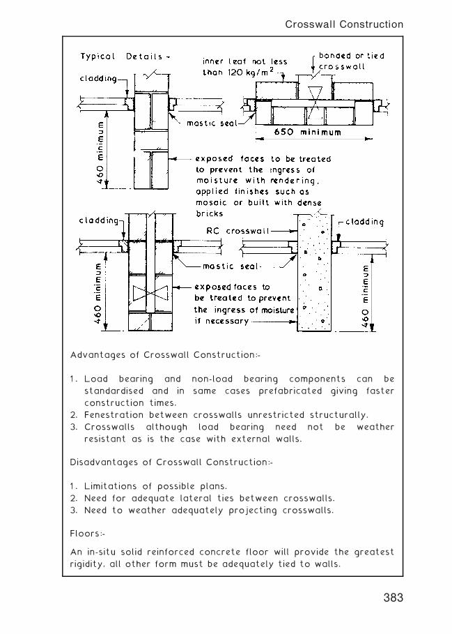
Advantages of Crosswall Construction:-
1 . Load bearing and non-load bearing components can be
standardised and in same cases prefabricated giving faster
construction times.
2. Fenestration between crosswalls unrestricted structurally.
3. Crosswalls although load bearing need not be weather
resistant as is the case with external walls.
Disadvantages of Crosswall Construction:-
1 . Limitations of possible plans.
2. Need for adequate lateral ties between crosswalls.
3. Need to weather adequately projecting crosswalls.
Floors:-
An in-situ solid reinforced concrete floor will provide the greatest
rigidity, all other form must be adequately tied to walls.
383
Crosswall Construction
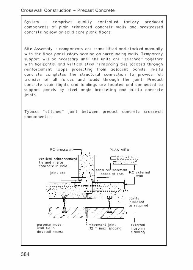
System ~ comprises quality controlled factory produced
components of plain reinforced concrete walls and prestressed
concrete hollow or solid core plank floors.
Site Assembly ~ components are crane lifted and stacked manually
with the floor panel edges bearing on surrounding walls. Temporary
support will be necessary until the units are ``stitched'' together
with horizontal and vertical steel reinforcing ties located through
reinforcement loops projecting from adjacent panels. In-situ
concrete completes the structural connection to provide full
transfer of all forces and loads through the joint. Precast
concrete stair flights and landings are located and connected to
support panels by steel angle bracketing and in-situ concrete
joints.
Typical ``stitched'' joint between precast concrete crosswall
components ~
PLAN VIEWRC crosswall
vertical reinforcementtie and in-situconcrete in void
joint seal RC externalwall
cavityinsulatedas required
externalmasonrycladding
movement joint(12 m max. spacing)
purpose madewall tie indovetail recess
panel reinforcement
looped at ends
384
Crosswall Construction -- Precast Concrete
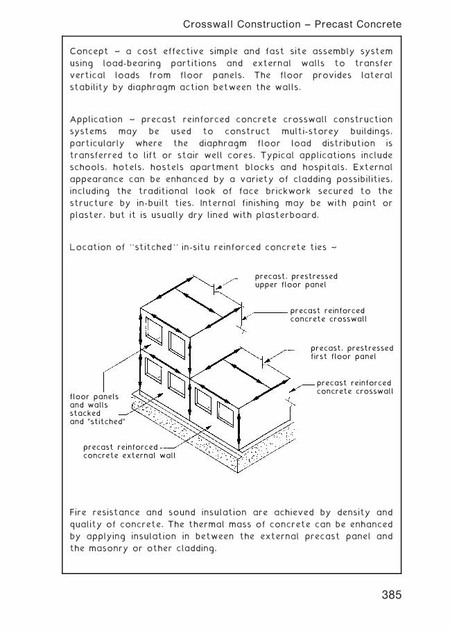
Concept ~ a cost effective simple and fast site assembly system
using load-bearing partitions and external walls to transfer
vertical loads from floor panels. The floor provides lateral
stability by diaphragm action between the walls.
Application ~ precast reinforced concrete crosswall construction
systems may be used to construct multi-storey buildings,
particularly where the diaphragm floor load distribution is
transferred to lift or stair well cores. Typical applications include
schools, hotels, hostels apartment blocks and hospitals. External
appearance can be enhanced by a variety of cladding possibilities,
including the traditional look of face brickwork secured to the
structure by in-built ties. Internal finishing may be with paint or
plaster, but it is usually dry lined with plasterboard.
Location of ``stitched'' in-situ reinforced concrete ties ~
floor panelsand wallsstackedand "stitched"
precast reinforcedconcrete external wall
precast reinforcedconcrete crosswall
precast, prestressedfirst floor panel
precast reinforcedconcrete crosswall
precast, prestressedupper floor panel
Fire resistance and sound insulation are achieved by density and
quality of concrete. The thermal mass of concrete can be enhanced
by applying insulation in between the external precast panel and
the masonry or other cladding.
385
Crosswall Construction -- Precast Concrete
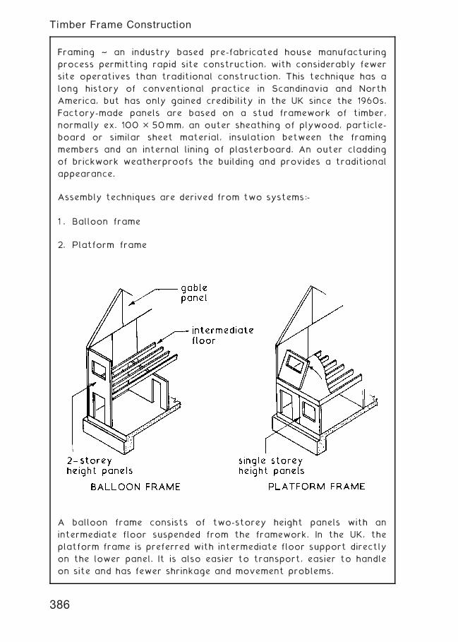
Framing ~ an industry based pre-fabricated house manufacturing
process permitting rapid site construction, with considerably fewer
site operatives than traditional construction. This technique has a
long history of conventional practice in Scandinavia and North
America, but has only gained credibility in the UK since the 1960s.
Factory-made panels are based on a stud framework of timber,
normally ex. 100 � 50mm, an outer sheathing of plywood, particle-
board or similar sheet material, insulation between the framing
members and an internal lining of plasterboard. An outer cladding
of brickwork weatherproofs the building and provides a traditional
appearance.
Assembly techniques are derived from two systems:-
1 . Balloon frame
2. Platform frame
A balloon frame consists of two-storey height panels with an
intermediate floor suspended from the framework. In the UK, the
platform frame is preferred with intermediate floor support directly
on the lower panel. It is also easier to transport, easier to handle
on site and has fewer shrinkage and movement problems.
386
Timber Frame Construction
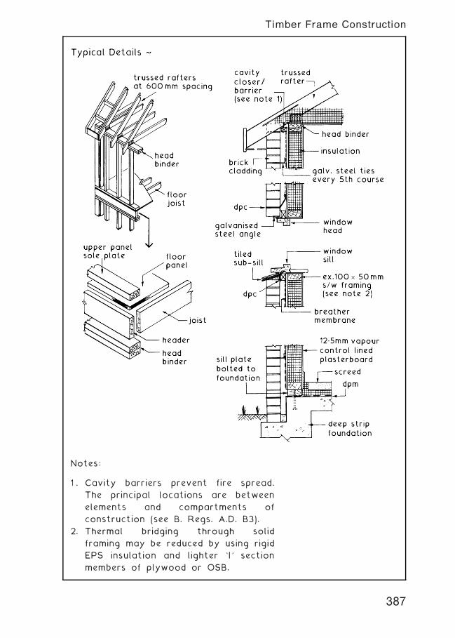
Notes:
1 . Cavity barriers prevent fire spread.
The principal locations are between
elements and compartments of
construction (see B. Regs. A.D. B3).
2. Thermal bridging through solid
framing may be reduced by using rigid
EPS insulation and lighter `I' section
members of plywood or OSB.
387
Timber Frame Construction
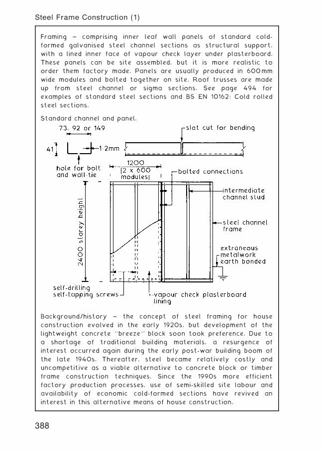
Framing ~ comprising inner leaf wall panels of standard cold-
formed galvanised steel channel sections as structural support,
with a lined inner face of vapour check layer under plasterboard.
These panels can be site assembled, but it is more realistic to
order them factory made. Panels are usually produced in 600mm
wide modules and bolted together on site. Roof trusses are made
up from steel channel or sigma sections. See page 494 for
examples of standard steel sections and BS EN 10162: Cold rolled
steel sections.
Standard channel and panel.
Background/history ~ the concept of steel framing for house
construction evolved in the early 1920s, but development of the
lightweight concrete ``breeze'' block soon took preference. Due to
a shortage of traditional building materials, a resurgence of
interest occurred again during the early post-war building boom of
the late 1940s. Thereafter, steel became relatively costly and
uncompetitive as a viable alternative to concrete block or timber
frame construction techniques. Since the 1990s more efficient
factory production processes, use of semi-skilled site labour and
availability of economic cold-formed sections have revived an
interest in this alternative means of house construction.
388
Steel Frame Construction (1)
Typical Details ~
Eavesinsulated cavity closerbarrier (see BuildingRegs. A. D: B3,Section 6 [Vol. 1]and 9 [Vol. 2]) andplywood bracket
bolted channelsection truss
storey heightmodular frame
brickworkouter leaf
channel sectionfloor joists
groundfloorslab
channel sectiontruss members
header binder or wallplatestud framing
fire retardant insulation
breather membranewall tie
50 mmcavity
insulation between studdingand into cavity
Intermediate floor Ground floor
plaster-boardplywooddeck
dpc
channelsectionfloorjoists
insulated cavitybarrier/fire stop ifa compartment floor
concrete slabor beam andblock floor
dpm
insulation
screedanchorbolt
12.5 mm vapour checkplasterboard screwedto stud framework
Advantages ~
• Factory made, therefore produced to quality controlled
standards and tolerances.
• Relatively simple to assemble on site † bolted connections in
pre-formed holes.
• Dimensionally stable, consistent composition, insignificant
movement.
• Unaffected by moisture, therefore will not rot.
• Does not burn.
• Inedible by insects.
• Roof spans potentially long relative to weight.
Disadvantages ~
• Possibility of corrosion if galvanised protective layer is
damaged.
• Deforms at high temperature, therefore unpredictable in fire.
• Electricity conductor † must be earthed.
389
Steel Frame Construction (2)
Claddings to External Walls ~ external walls of block or timber
frame construction can be clad with tiles, timber boards or plastic
board sections. The tiles used are plain roofing tiles with either a
straight or patterned bottom edge. They are applied to the
vertical surface in the same manner as tiles laid on a sloping
surface (see pages 401 to 403) except that the gauge can be wider
and each tile is twice nailed. External and internal angles can be
formed using special tiles or they can be mitred. Timber boards
such as matchboarding and shiplap can be fixed vertically to
horizontal battens or horizontally to vertical battens. Plastic
moulded board claddings can be applied in a similar manner. The
battens to which the claddings are fixed should be treated with a
preservative against fungi and beetle attack and should be fixed
with corrosion resistant nails.
Cladding to External Walls
390
Roofs---Performance Requirements
391
Roofs ~ these can be classified as either:-
Flat † pitch from 0� to 10�
Pitched † pitch over 10�
It is worth noting that for design purposes roof pitches over 70�
are classified as walls.
Roofs can be designed in many different forms and in combinations
of these forms some of which would not be suitable and/or
economic for domestic properties.
392
Basic Roof Forms
393
Basic Roof Forms
394
Basic Roof Forms
Pitched Roofs ~ the primary functions of any domestic roof are
to:-
1 . Provide an adequate barrier to the penetration of the
elements.
2. Maintain the internal environment by providing an adequate
resistance to heat loss.
A roof is in a very exposed situation and must therefore be
designed and constructed in such a manner as to:-
1 . Safely resist all imposed loadings such as snow and wind.
2. Be capable of accommodating thermal and moisture
movements.
3. Be durable so as to give a satisfactory performance and
reduce maintenance to a minimum.
Timber Pitched Roofs up to 7.5 m Span
395
Timber Pitched Roofs up to 7.5 m Span---Types
396
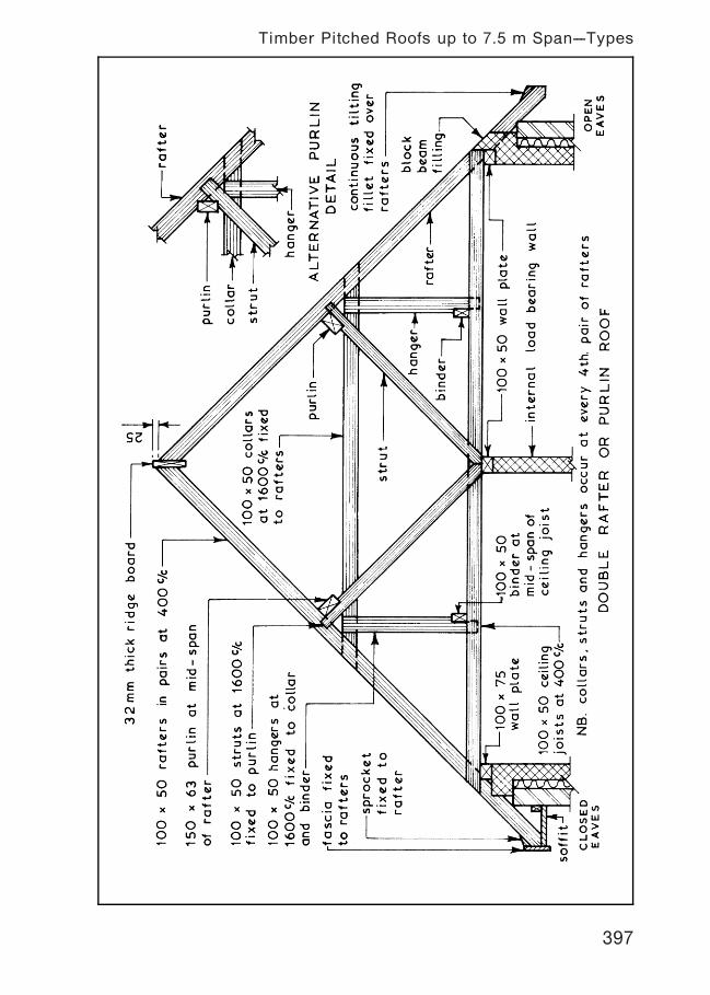
Timber Pitched Roofs up to 7.5 m Span---Types
397
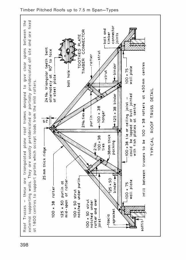
Roof
Tru
sses
~these
are
triangula
ted
pla
ne
roof
frames
designed
to
give
clear
spans
between
the
extern
alsupport
ing
walls.They
are
usually
pre
fabricated
or
part
ially
pre
fabricated
off
site
and
are
fixed
at
1„800
centre
sto
support
purlins
which
accept
loads
from
the
infill
rafters
.
Timber Pitched Roofs up to 7.5 m Span---Types
398
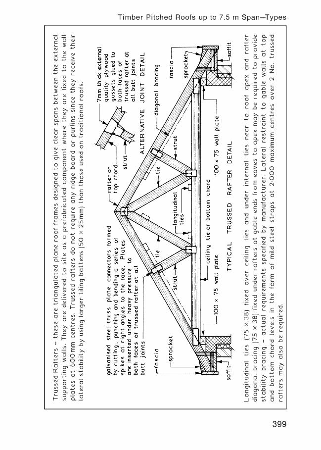
Tru
ssed
Rafters
~these
are
triangula
ted
pla
ne
roofframesdesigned
to
give
clearspansbetween
the
extern
al
support
ing
walls.They
are
delivere
dto
site
as
apre
fabricated
component
where
they
are
fixed
to
the
wall
pla
tes
at
600mm
centre
s.Tru
ssed
rafters
do
not
require
any
ridge
board
orpurlins
since
they
receive
their
latera
lstability
by
using
larg
ertiling
battens(5
0�
25mm)than
thoseused
on
tra
ditionalro
ofs.
Longitudinal
ties
(75�
38)
fixed
over
ceiling
ties
and
under
intern
al
ties
near
to
roof
apex
and
rafter
diagonalbra
cing
(75�
38)fixed
underra
fters
at
gable
ends
from
eaves
to
apex
may
be
required
to
pro
vide
stability
bra
cing
†actualre
quirements
specified
by
manufa
cture
r.Latera
lre
stra
int
to
gable
walls
at
top
and
bottom
chord
levels
inthe
form
of
mild
steelstra
ps
at
2„0
00
maxim
um
centre
sover
2No.tru
ssed
rafters
may
also
be
required.
Timber Pitched Roofs up to 7.5 m Span---Types
399
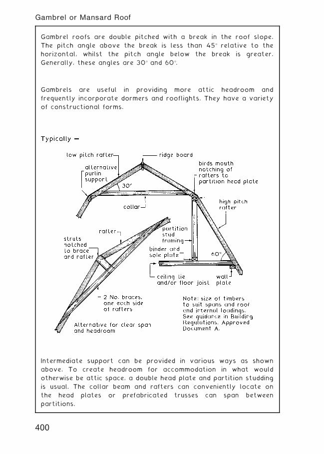
Gambrel roofs are double pitched with a break in the roof slope.
The pitch angle above the break is less than 45� relative to the
horizontal, whilst the pitch angle below the break is greater.
Generally, these angles are 30� and 60�.
Gambrels are useful in providing more attic headroom and
frequently incorporate dormers and rooflights. They have a variety
of constructional forms.
Intermediate support can be provided in various ways as shown
above. To create headroom for accommodation in what would
otherwise be attic space, a double head plate and partition studding
is usual. The collar beam and rafters can conveniently locate on
the head plates or prefabricated trusses can span between
partitions.
400
Gambrel or Mansard Roof
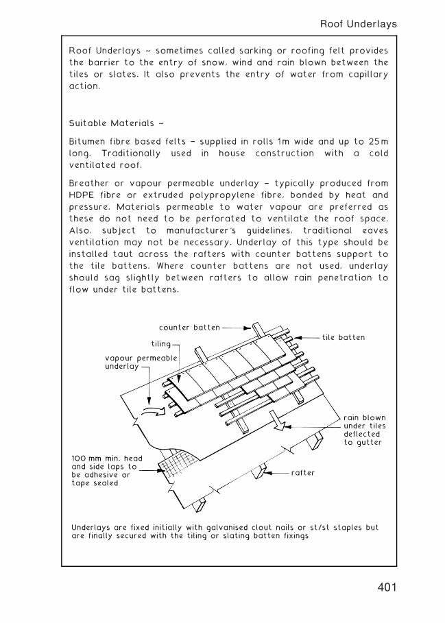
Roof Underlays ~ sometimes called sarking or roofing felt provides
the barrier to the entry of snow, wind and rain blown between the
tiles or slates. It also prevents the entry of water from capillary
action.
Suitable Materials ~
Bitumen fibre based felts † supplied in rolls 1m wide and up to 25m
long. Traditionally used in house construction with a cold
ventilated roof.
Breather or vapour permeable underlay † typically produced from
HDPE fibre or extruded polypropylene fibre, bonded by heat and
pressure. Materials permeable to water vapour are preferred as
these do not need to be perforated to ventilate the roof space.
Also, subject to manufacturer's guidelines, traditional eaves
ventilation may not be necessary. Underlay of this type should be
installed taut across the rafters with counter battens support to
the tile battens. Where counter battens are not used, underlay
should sag slightly between rafters to allow rain penetration to
flow under tile battens.
Underlays are fixed initially with galvanised clout nails or st/st staples butare finally secured with the tiling or slating batten fixings
tile batten
rain blownunder tilesdeflectedto gutter
rafter
100 mm min. headand side laps tobe adhesive ortape sealed
vapour permeableunderlay
counter batten
tiling
401
Roof Underlays
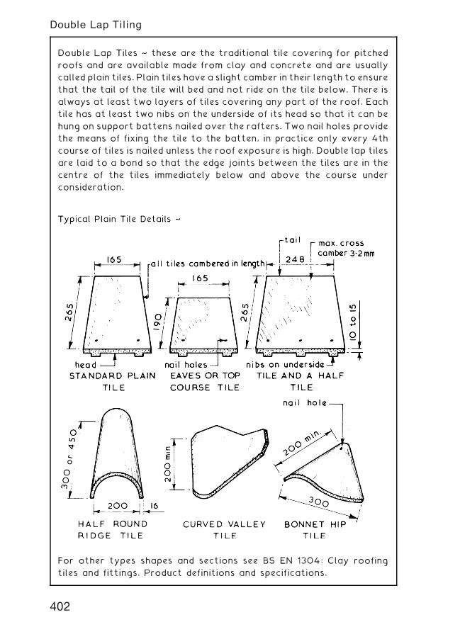
Double Lap Tiles ~ these are the traditional tile covering for pitched
roofs and are available made from clay and concrete and are usually
called plain tiles. Plain tiles have a slight camber in their length to ensure
that the tail of the tile will bed and not ride on the tile below. There is
always at least two layers of tiles covering any part of the roof. Each
tile has at least two nibs on the underside of its head so that it can be
hung on support battens nailed over the rafters. Two nail holes provide
the means of fixing the tile to the batten, in practice only every 4th
course of tiles is nailed unless the roof exposure is high. Double lap tiles
are laid to a bond so that the edge joints between the tiles are in the
centre of the tiles immediately below and above the course under
consideration.
For other types shapes and sections see BS EN 1304: Clay roofing
tiles and fittings. Product definitions and specifications.
402
Double Lap Tiling
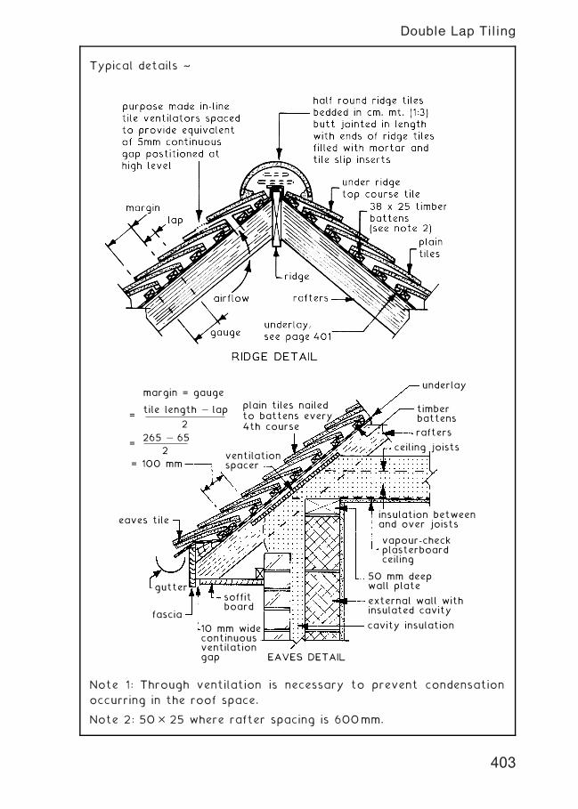
Typical details ~
timberbattens
underlay
rafters
ceiling joists
insulation betweenand over joists
vapour-checkplasterboardceiling
50 mm deepwall plate
external wall withinsulated cavity
cavity insulation
EAVES DETAIL
10 mm widecontinuousventilationgap
fascia
soffitboard
gutter
eaves tile
margin = gauge
ventilationspacer
plain tiles nailedto battens every4th course
=tile length — lap
2
= 100 mm
=265 — 65
2
Note 1: Through ventilation is necessary to prevent condensation
occurring in the roof space.
Note 2: 50� 25 where rafter spacing is 600mm.
403
Double Lap Tiling
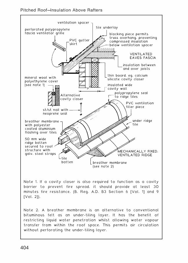
Note 1. If a cavity closer is also required to function as a cavity
barrier to prevent fire spread, it should provide at least 30
minutes fire resistance, (B. Reg. A.D. B3 Section 6 [Vol. 1] and 9
[Vol. 2]).
Note 2. A breather membrane is an alternative to conventional
bituminous felt as an under-tiling layer. It has the benefit of
restricting liquid water penetration whilst allowing water vapour
transfer from within the roof space. This permits air circulation
without perforating the under-tiling layer.
404
Pitched Roof---Insulation Above Rafters
Where a roof space is used for habitable space, insulation must be
provided within the roof slope. Insulation above the rafters (as
shown) creates a `warm roof', eliminating the need for continuous
ventilation. Insulation placed between the rafters creates a `cold
roof', requiring a continuous 50mm ventilation void above the
insulation to prevent the possible occurrence of interstitial
condensation.
Suitable rigid insulants include; low density polyisocyanurate (PIR)
foam, reinforced with long strand glass fibres, both faces bonded
to aluminium foil with joints aluminium foil taped on the upper
surface; high density mineral wool slabs over rafters with less
dense mineral wool between rafters.
An alternative location for the breather membrane is under the
counter battens. This is often preferred as the insulation board will
provide uniform support for the underlay. Otherwise, extra
insulation could be provided between the counter battens, retaining
sufficient space for the underlay to sag between rafter positions
to permit any rainwater penetration to drain to eaves.
405
Eaves and Ridge---Alternative Treatment
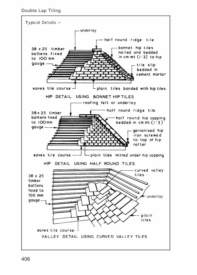
Double Lap Tiling
406
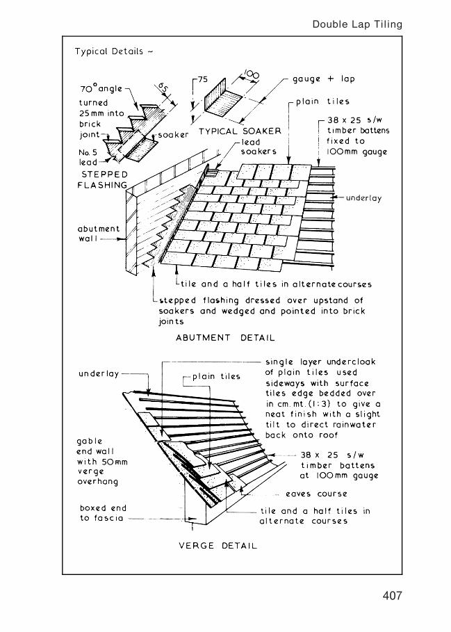
Double Lap Tiling
407
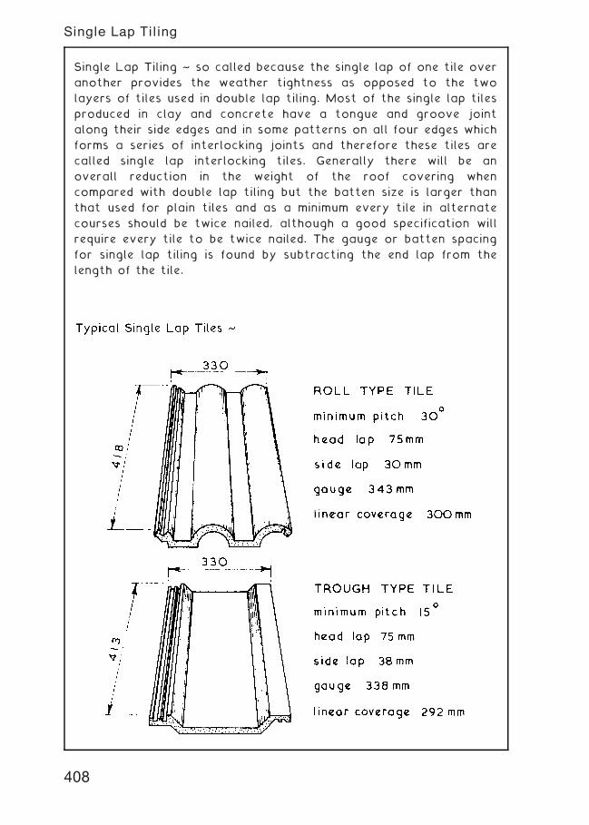
Single Lap Tiling ~ so called because the single lap of one tile over
another provides the weather tightness as opposed to the two
layers of tiles used in double lap tiling. Most of the single lap tiles
produced in clay and concrete have a tongue and groove joint
along their side edges and in some patterns on all four edges which
forms a series of interlocking joints and therefore these tiles are
called single lap interlocking tiles. Generally there will be an
overall reduction in the weight of the roof covering when
compared with double lap tiling but the batten size is larger than
that used for plain tiles and as a minimum every tile in alternate
courses should be twice nailed, although a good specification will
require every tile to be twice nailed. The gauge or batten spacing
for single lap tiling is found by subtracting the end lap from the
length of the tile.
408
Single Lap Tiling
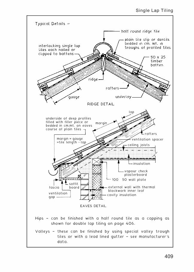
lap
margin
underside of deep profilesfilled with filler piece orbedded in cm.mt. on eavescourse of plain tiles
margin = gauge=tile length — lap
fascia
ventilationgap
soffitboard
cavity insulation
external wall with thermalblockwork inner leaf
100 × 50 wall plate
vapour checkplasterboard
insulation
ceiling joists
ventilation spacer
rafters
EAVES DETAIL
Hips † can be finished with a half round tile as a capping as
shown for double lap tiling on page 406.
Valleys † these can be finished by using special valley trough
tiles or with a lead lined gutter † see manufacturer's
data.
409
Single Lap Tiling
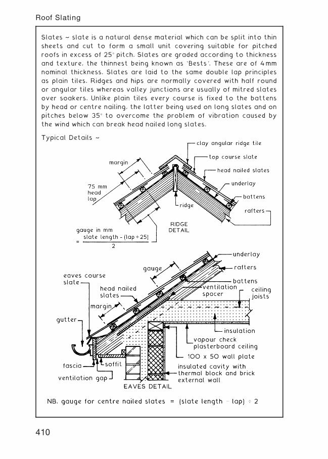
Slates ~ slate is a natural dense material which can be split into thin
sheets and cut to form a small unit covering suitable for pitched
roofs in excess of 25� pitch. Slates are graded according to thickness
and texture, the thinnest being known as `Bests'. These are of 4mm
nominal thickness. Slates are laid to the same double lap principles
as plain tiles. Ridges and hips are normally covered with half round
or angular tiles whereas valley junctions are usually of mitred slates
over soakers. Unlike plain tiles every course is fixed to the battens
by head or centre nailing, the latter being used on long slates and on
pitches below 35� to overcome the problem of vibration caused by
the wind which can break head nailed long slates.
Typical Details ~
410
Roof Slating
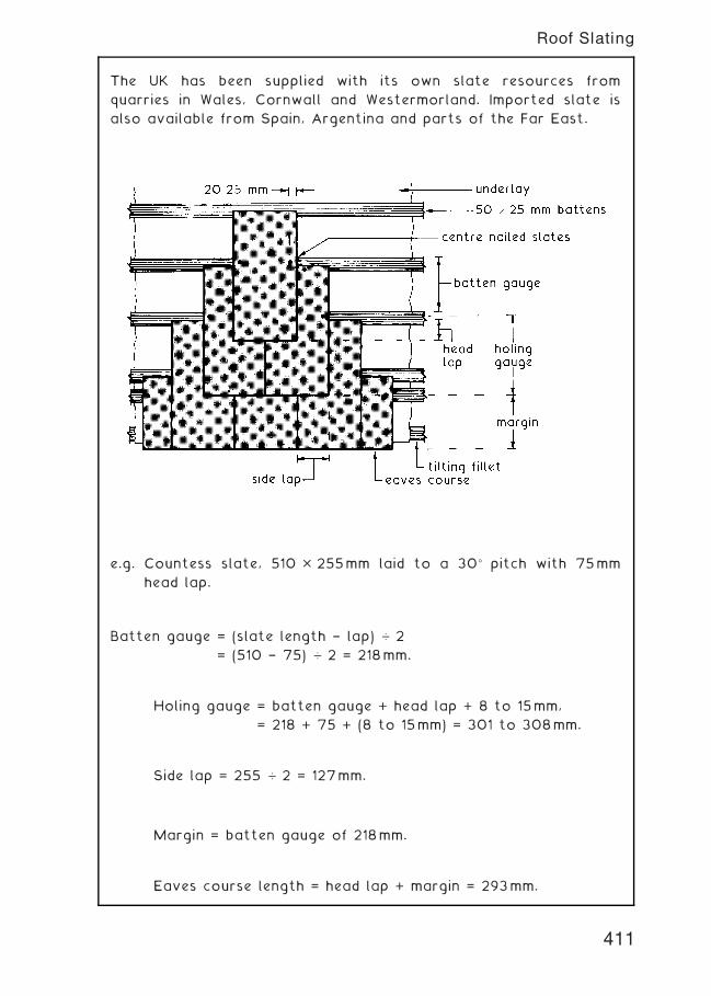
The UK has been supplied with its own slate resources from
quarries in Wales, Cornwall and Westermorland. Imported slate is
also available from Spain, Argentina and parts of the Far East.
e.g. Countess slate, 510 � 255mm laid to a 30� pitch with 75mm
head lap.
Batten gauge = (slate length † lap) … 2
= (510 † 75) … 2 = 218mm.
Holing gauge = batten gauge + head lap + 8 to 15mm,
= 218 + 75 + (8 to 15mm) = 301 to 308mm.
Side lap = 255 … 2 = 127mm.
Margin = batten gauge of 218mm.
Eaves course length = head lap + margin = 293mm.
411
Roof Slating
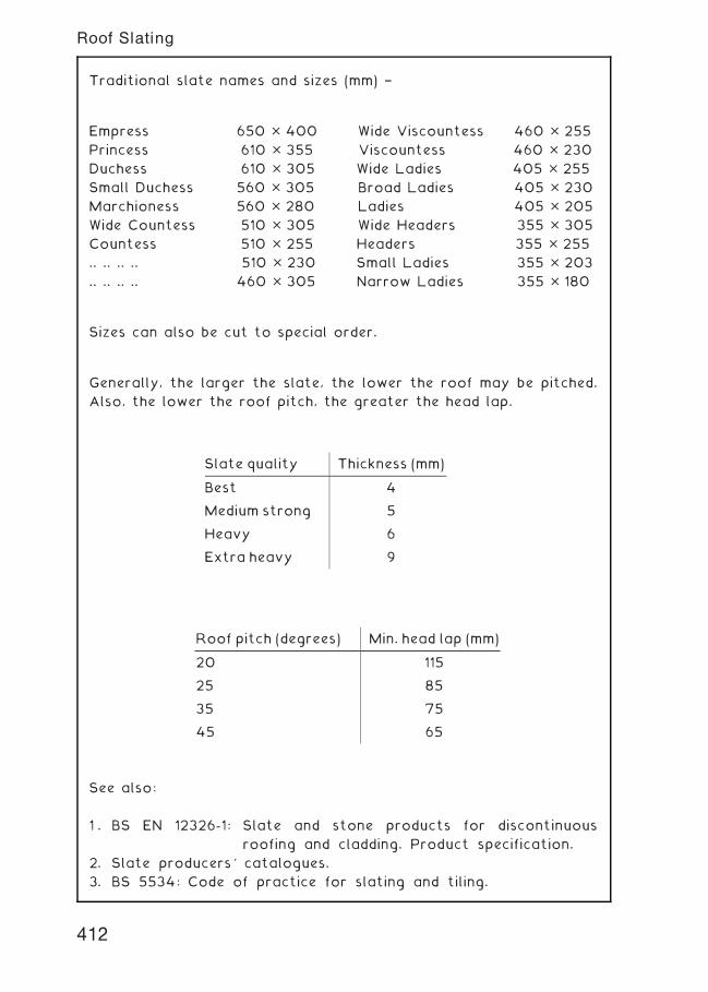
Traditional slate names and sizes (mm) †
Empress 650 � 400 Wide Viscountess 460 � 255
Princess 610 � 355 Viscountess 460 � 230
Duchess 610 � 305 Wide Ladies 405 � 255
Small Duchess 560 � 305 Broad Ladies 405 � 230
Marchioness 560 � 280 Ladies 405 � 205
Wide Countess 510 � 305 Wide Headers 355 � 305
Countess 510 � 255 Headers 355 � 255
.. .. .. .. 510 � 230 Small Ladies 355 � 203
.. .. .. .. 460 � 305 Narrow Ladies 355 � 180
Sizes can also be cut to special order.
Generally, the larger the slate, the lower the roof may be pitched.
Also, the lower the roof pitch, the greater the head lap.
See also:
1 . BS EN 12326-1: Slate and stone products for discontinuous
roofing and cladding. Product specification.
2. Slate producers' catalogues.
3. BS 5534: Code of practice for slating and tiling.
Slate quality Thickness (mm)
Best 4
Medium strong 5
Heavy 6
Extra heavy 9
Roof pitch (degrees) Min. head lap (mm)
20 115
25 85
35 75
45 65
412
Roof Slating
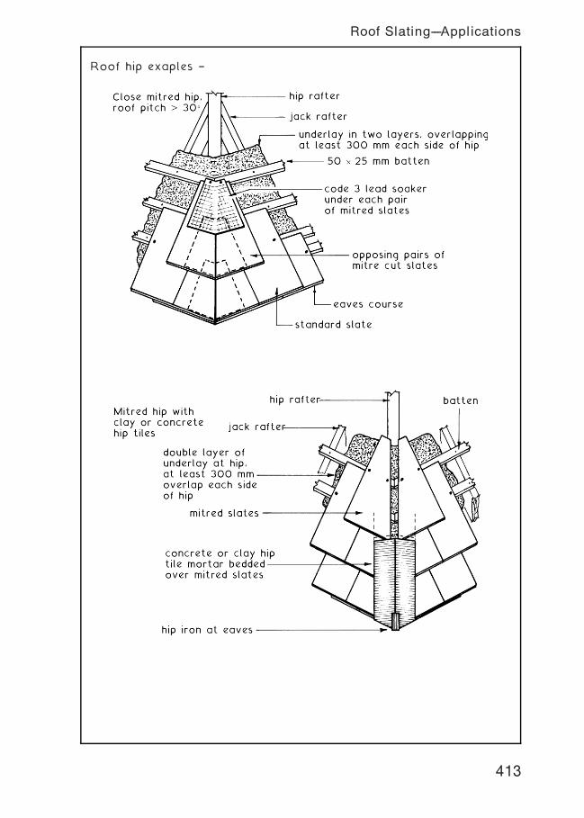
Roof hip exaples †
Roof Slating---Applications
413
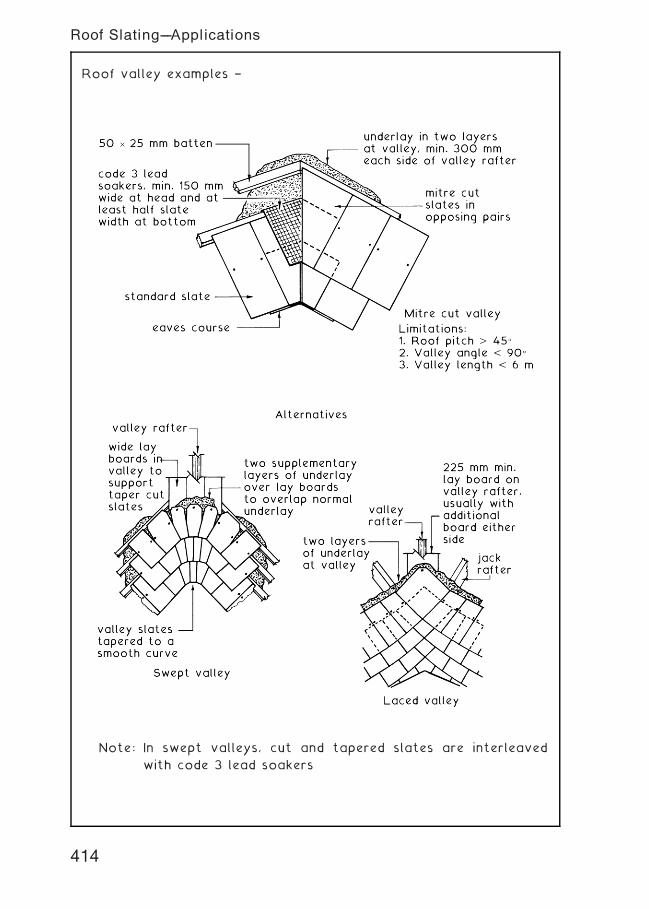
Roof valley examples †
Note: In swept valleys, cut and tapered slates are interleaved
with code 3 lead soakers
414
Roof Slating---Applications
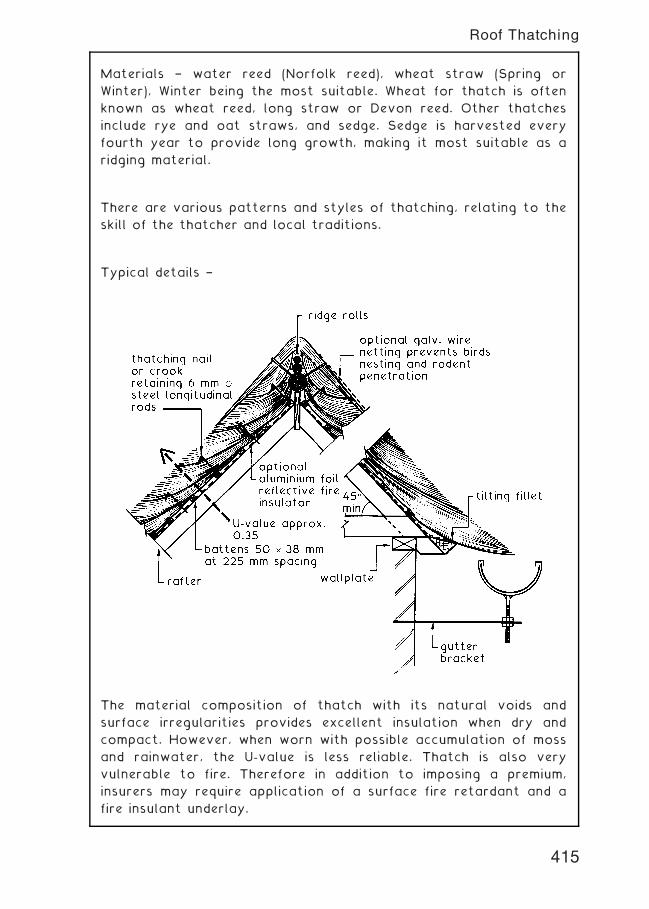
Materials † water reed (Norfolk reed), wheat straw (Spring or
Winter), Winter being the most suitable. Wheat for thatch is often
known as wheat reed, long straw or Devon reed. Other thatches
include rye and oat straws, and sedge. Sedge is harvested every
fourth year to provide long growth, making it most suitable as a
ridging material.
There are various patterns and styles of thatching, relating to the
skill of the thatcher and local traditions.
Typical details †
The material composition of thatch with its natural voids and
surface irregularities provides excellent insulation when dry and
compact. However, when worn with possible accumulation of moss
and rainwater, the U-value is less reliable. Thatch is also very
vulnerable to fire. Therefore in addition to imposing a premium,
insurers may require application of a surface fire retardant and a
fire insulant underlay.
415
Roof Thatching
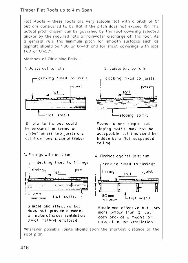
Flat Roofs ~ these roofs are very seldom flat with a pitch of 0�
but are considered to be flat if the pitch does not exceed 10�. The
actual pitch chosen can be governed by the roof covering selected
and/or by the required rate of rainwater discharge off the roof. As
a general rule the minimum pitch for smooth surfaces such as
asphalt should be 1:80 or 0�†430 and for sheet coverings with laps
1:60 or 0�†570.
Methods of Obtaining Falls ~
Wherever possible joists should span the shortest distance of the
roof plan.
416
Timber Flat Roofs up to 4 m Span
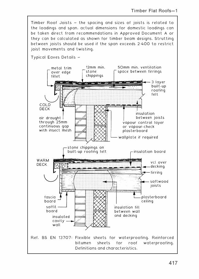
Timber Roof Joists ~ the spacing and sizes of joists is related to
the loadings and span, actual dimensions for domestic loadings can
be taken direct from recommendations in Approved Document A or
they can be calculated as shown for timber beam designs. Strutting
between joists should be used if the span exceeds 2„400 to restrict
joist movements and twisting.
Typical Eaves Details ~
Ref. BS EN 13707: Flexible sheets for waterproofing. Reinforced
bitumen sheets for roof waterproofing.
Definitions and characteristics.
Timber Flat Roofs---1
417
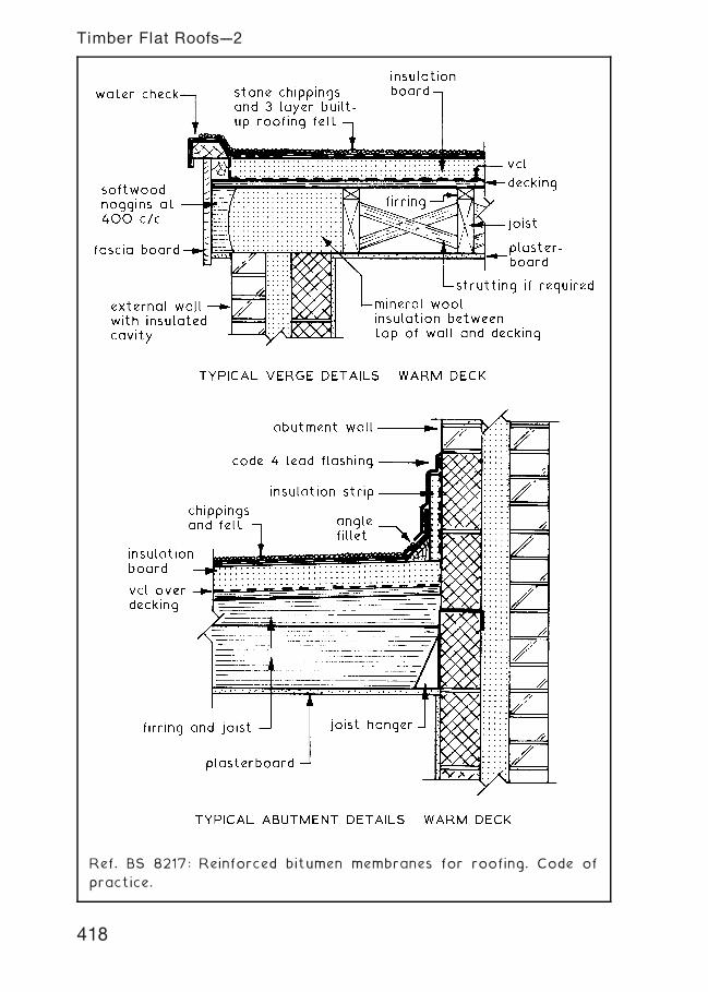
Ref. BS 8217: Reinforced bitumen membranes for roofing. Code of
practice.
418
Timber Flat Roofs---2
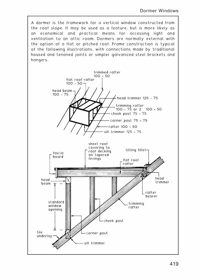
A dormer is the framework for a vertical window constructed from
the roof slope. It may be used as a feature, but is more likely as
an economical and practical means for accessing light and
ventilation to an attic room. Dormers are normally external with
the option of a flat or pitched roof. Frame construction is typical
of the following illustrations, with connections made by traditional
housed and tenoned joints or simpler galvanized steel brackets and
hangers.
419
Dormer Windows
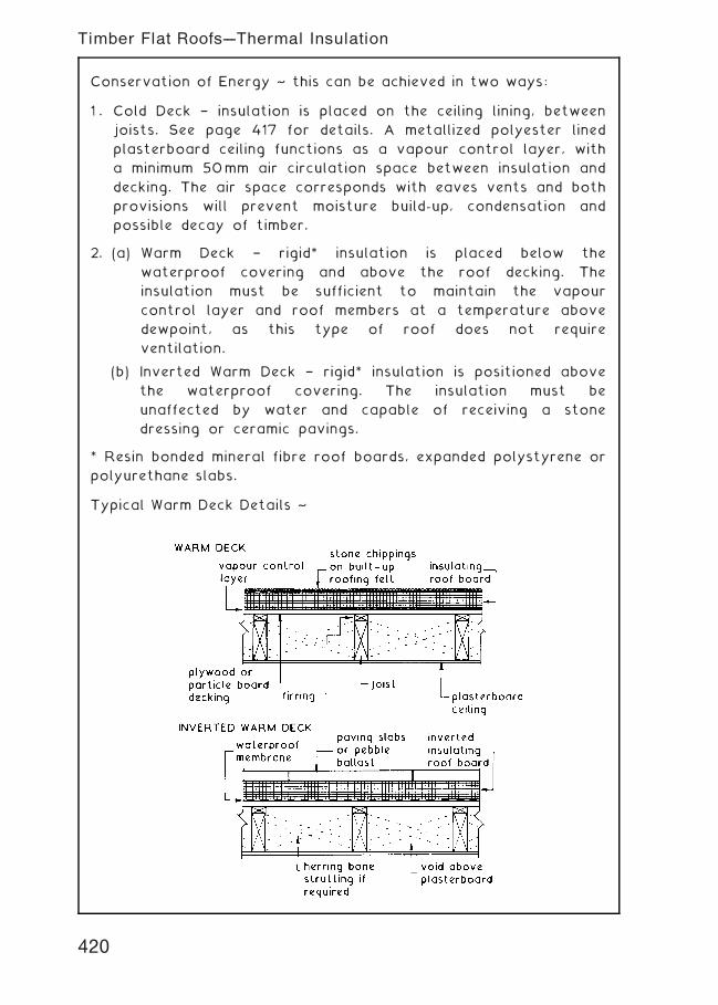
Conservation of Energy ~ this can be achieved in two ways:
1 . Cold Deck † insulation is placed on the ceiling lining, between
joists. See page 417 for details. A metallized polyester lined
plasterboard ceiling functions as a vapour control layer, with
a minimum 50mm air circulation space between insulation and
decking. The air space corresponds with eaves vents and both
provisions will prevent moisture build-up, condensation and
possible decay of timber.
2. (a) Warm Deck † rigid* insulation is placed below the
waterproof covering and above the roof decking. The
insulation must be sufficient to maintain the vapour
control layer and roof members at a temperature above
dewpoint, as this type of roof does not require
ventilation.
(b) Inverted Warm Deck † rigid* insulation is positioned above
the waterproof covering. The insulation must be
unaffected by water and capable of receiving a stone
dressing or ceramic pavings.
* Resin bonded mineral fibre roof boards, expanded polystyrene or
polyurethane slabs.
Typical Warm Deck Details ~
420
Timber Flat Roofs---Thermal Insulation
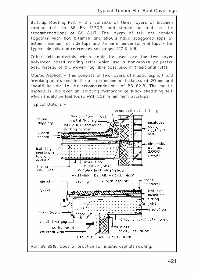
Built-up Roofing Felt ~ this consists of three layers of bitumen
roofing felt to BS EN 13707, and should be laid to the
recommendations of BS 8217. The layers of felt are bonded
together with hot bitumen and should have staggered laps of
50mm minimum for side laps and 75mm minimum for end laps † for
typical details and references see pages 417 & 418.
Other felt materials which could be used are the two layer
polyester based roofing felts which use a non-woven polyester
base instead of the woven rag fibre base used in traditional felts.
Mastic Asphalt ~ this consists of two layers of mastic asphalt laid
breaking joints and built up to a minimum thickness of 20mm and
should be laid to the recommendations of BS 8218. The mastic
asphalt is laid over an isolating membrane of black sheathing felt
which should be laid loose with 50mm minimum overlaps.
Typical Datails ~
Ref. BS 8218: Code of practice for mastic asphalt roofing.
421
Typical Timber Flat Roof Coverings
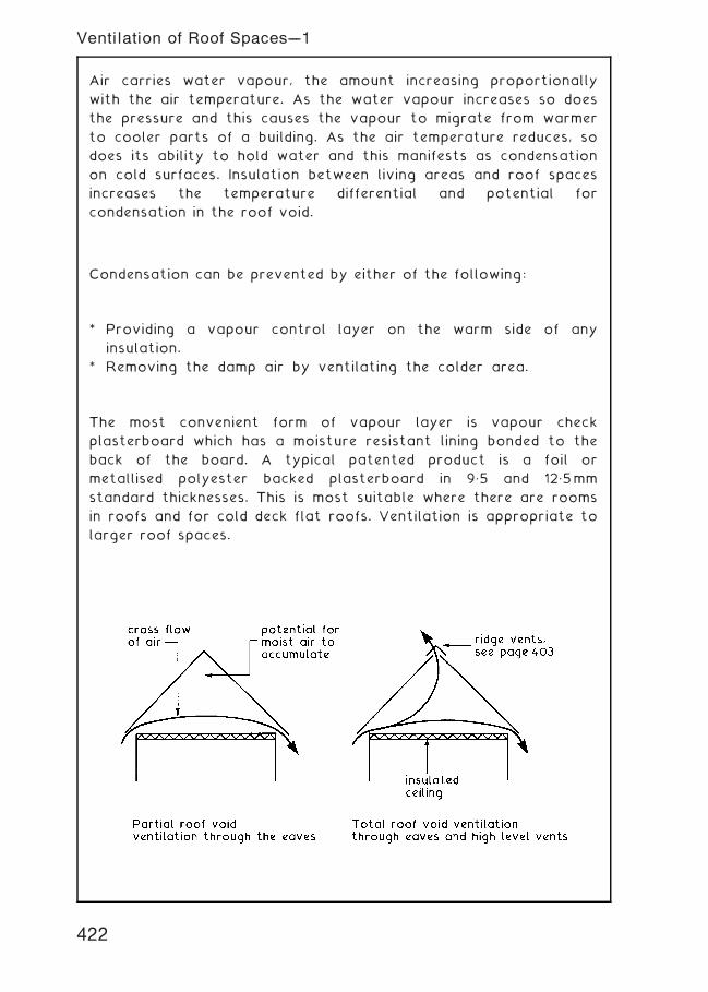
Air carries water vapour, the amount increasing proportionally
with the air temperature. As the water vapour increases so does
the pressure and this causes the vapour to migrate from warmer
to cooler parts of a building. As the air temperature reduces, so
does its ability to hold water and this manifests as condensation
on cold surfaces. Insulation between living areas and roof spaces
increases the temperature differential and potential for
condensation in the roof void.
Condensation can be prevented by either of the following:
* Providing a vapour control layer on the warm side of any
insulation.
* Removing the damp air by ventilating the colder area.
The most convenient form of vapour layer is vapour check
plasterboard which has a moisture resistant lining bonded to the
back of the board. A typical patented product is a foil or
metallised polyester backed plasterboard in 9„5 and 12„5mm
standard thicknesses. This is most suitable where there are rooms
in roofs and for cold deck flat roofs. Ventilation is appropriate to
larger roof spaces.
422
Ventilation of Roof Spaces---1
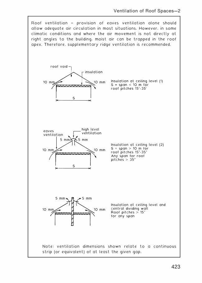
Roof ventilation † provision of eaves ventilation alone should
allow adequate air circulation in most situations. However, in some
climatic conditions and where the air movement is not directly at
right angles to the building, moist air can be trapped in the roof
apex. Therefore, supplementary ridge ventilation is recommended.
Note: ventilation dimensions shown relate to a continuous
strip (or equivalent) of at least the given gap.
423
Ventilation of Roof Spaces---2
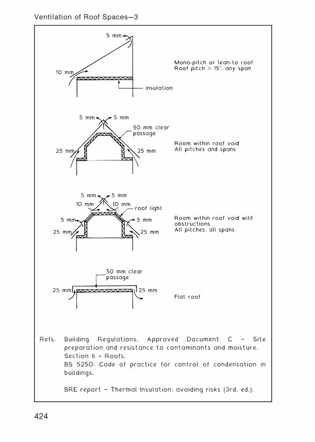
Refs. Building Regulations, Approved Document C † Site
preparation and resistance to contaminants and moisture.
Section 6 † Roofs.
BS 5250: Code of practice for control of condensation in
buildings.
BRE report † Thermal Insulation: avoiding risks (3rd. ed.).
424
Ventilation of Roof Spaces---3
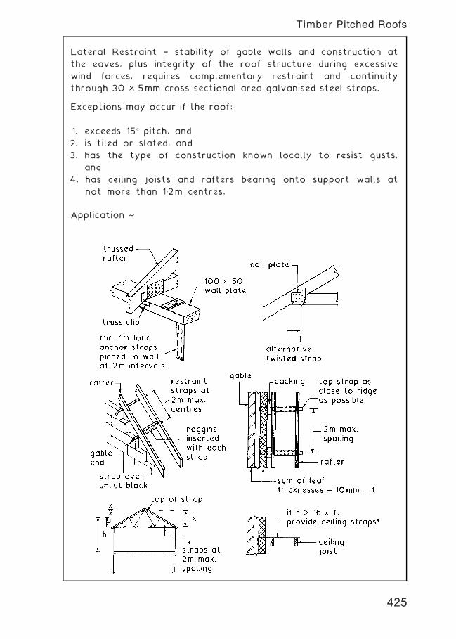
Lateral Restraint † stability of gable walls and construction at
the eaves, plus integrity of the roof structure during excessive
wind forces, requires complementary restraint and continuity
through 30 � 5mm cross sectional area galvanised steel straps.
Exceptions may occur if the roof:-
1. exceeds 15� pitch, and
2. is tiled or slated, and
3. has the type of construction known locally to resist gusts,
and
4. has ceiling joists and rafters bearing onto support walls at
not more than 1�2m centres.
Application ~
425
Timber Pitched Roofs
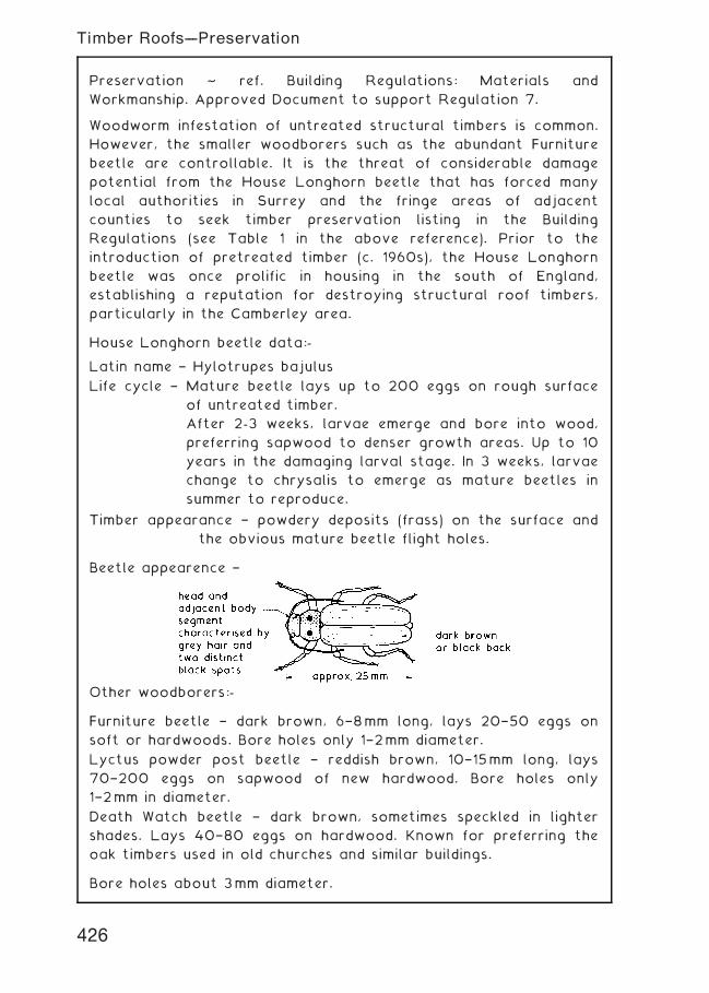
Preservation ~ ref. Building Regulations: Materials and
Workmanship. Approved Document to support Regulation 7.
Woodworm infestation of untreated structural timbers is common.
However, the smaller woodborers such as the abundant Furniture
beetle are controllable. It is the threat of considerable damage
potential from the House Longhorn beetle that has forced many
local authorities in Surrey and the fringe areas of adjacent
counties to seek timber preservation listing in the Building
Regulations (see Table 1 in the above reference). Prior to the
introduction of pretreated timber (c. 1960s), the House Longhorn
beetle was once prolific in housing in the south of England,
establishing a reputation for destroying structural roof timbers,
particularly in the Camberley area.
House Longhorn beetle data:-
Latin name † Hylotrupes bajulus
Life cycle † Mature beetle lays up to 200 eggs on rough surface
of untreated timber.
After 2-3 weeks, larvae emerge and bore into wood,
preferring sapwood to denser growth areas. Up to 10
years in the damaging larval stage. In 3 weeks, larvae
change to chrysalis to emerge as mature beetles in
summer to reproduce.
Timber appearance † powdery deposits (frass) on the surface and
the obvious mature beetle flight holes.
Beetle appearence †
Other woodborers:-
Furniture beetle † dark brown, 6†8mm long, lays 20†50 eggs on
soft or hardwoods. Bore holes only 1†2mm diameter.
Lyctus powder post beetle † reddish brown, 10†15mm long, lays
70†200 eggs on sapwood of new hardwood. Bore holes only
1†2mm in diameter.
Death Watch beetle † dark brown, sometimes speckled in lighter
shades. Lays 40†80 eggs on hardwood. Known for preferring the
oak timbers used in old churches and similar buildings.
Bore holes about 3mm diameter.
426
Timber Roofs---Preservation
Preservation ~ treatment of timber to prevent damage from House
Longhorn beetle.
In the areas specified (see previous page), all softwood used in roof
structures including ceiling joists and any other softwood fixings
should be treated with insecticide prior to installation. Specific
chemicals and processes have not been listed in the Building
Regulations since the 1976 issue, although the processes detailed
then should suffice:-
1 . Treatment to BS 4072.*
2. Diffusion with sodium borate (boron salts).
3. Steeping for at least 10 mins in an organic solvent wood
preservative.
NB. Steeping or soaking in creosote will be effective, but problems
of local staining are likely.
BS 4072 provides guidance on an acceptable blend of copper,
chromium and arsenic known commercially as Tanalizing.
Application is at specialist timber yards by vacuum/pressure
impregnation in large cylindrical containers, but see note below.
Insect treatment adds about 10% to the cost of timber and also
enhances its resistance to moisture. Other parts of the structure,
e.g. floors and partitions are less exposed to woodworm damage
as they are enclosed. Also, there is a suggestion that if these
areas received treated timber, the toxic fumes could be harmful to
the health of building occupants. Current requirements for through
ventilation in roofs has the added benefit of discouraging wood
boring insects, as they prefer draught-free damp areas.
Refs. BS 4072: Copper/chromium/arsenic preparations for wood
preservation.*
BS 4261: Wood preservation. Vocabulary.
BS 5589: Code of practice for preservation of timber.
BS 8417: Preservation of timber. Recommendations.
BS 5707: Specification for preparations of wood preservatives
in organic solvents.
*Note: The EU are processing legislation which will prohibit the use
of CCA preservatives for domestic applications and in places where
the public may be in contact with it. Ref. CEN/TC 38.
427
Timber Roofs---Preservation
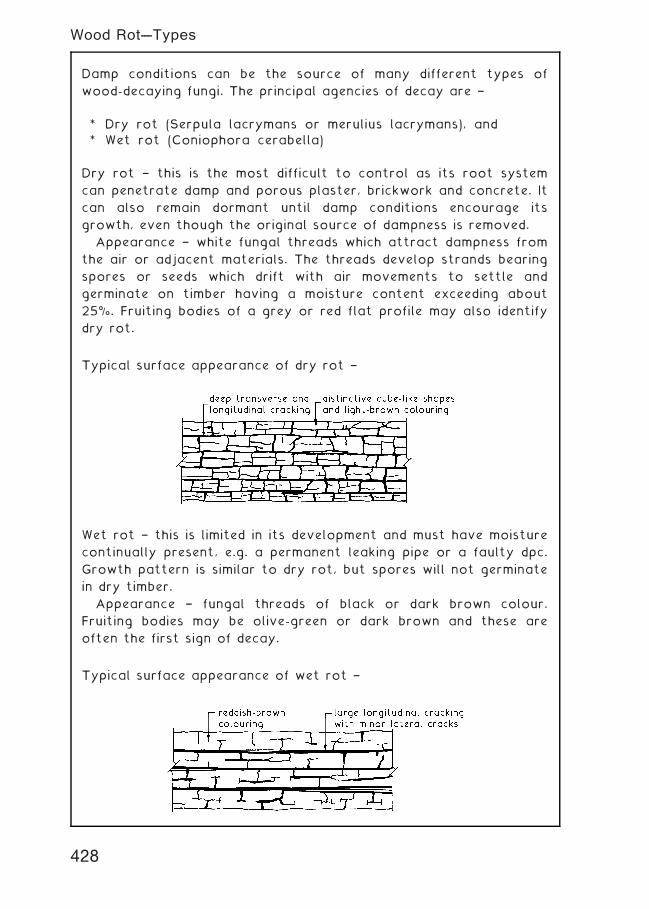
Damp conditions can be the source of many different types of
wood-decaying fungi. The principal agencies of decay are †
* Dry rot (Serpula lacrymans or merulius lacrymans), and
* Wet rot (Coniophora cerabella)
Dry rot † this is the most difficult to control as its root system
can penetrate damp and porous plaster, brickwork and concrete. It
can also remain dormant until damp conditions encourage its
growth, even though the original source of dampness is removed.
Appearance † white fungal threads which attract dampness from
the air or adjacent materials. The threads develop strands bearing
spores or seeds which drift with air movements to settle and
germinate on timber having a moisture content exceeding about
25%. Fruiting bodies of a grey or red flat profile may also identify
dry rot.
Typical surface appearance of dry rot †
Wet rot † this is limited in its development and must have moisture
continually present, e.g. a permanent leaking pipe or a faulty dpc.
Growth pattern is similar to dry rot, but spores will not germinate
in dry timber.
Appearance † fungal threads of black or dark brown colour.
Fruiting bodies may be olive-green or dark brown and these are
often the first sign of decay.
Typical surface appearance of wet rot †
428
Wood Rot---Types
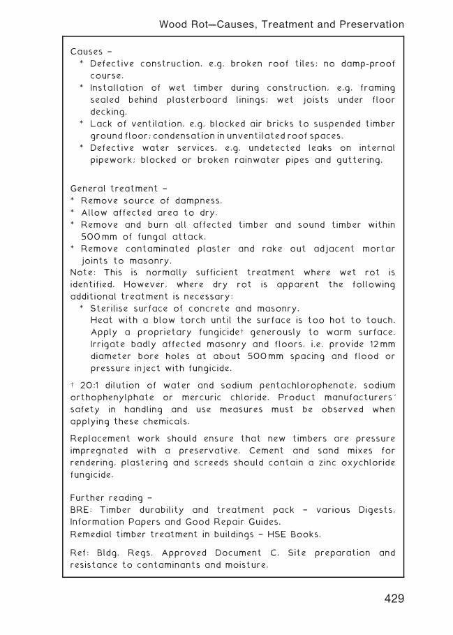
Causes †
* Defective construction, e.g. broken roof tiles; no damp-proof
course.
* Installation of wet timber during construction, e.g. framing
sealed behind plasterboard linings; wet joists under floor
decking.
* Lack of ventilation, e.g. blocked air bricks to suspended timber
ground floor; condensation in unventilated roof spaces.
* Defective water services, e.g. undetected leaks on internal
pipework; blocked or broken rainwater pipes and guttering.
General treatment †
* Remove source of dampness.
* Allow affected area to dry.
* Remove and burn all affected timber and sound timber within
500mm of fungal attack.
* Remove contaminated plaster and rake out adjacent mortar
joints to masonry.
Note: This is normally sufficient treatment where wet rot is
identified. However, where dry rot is apparent the following
additional treatment is necessary:
* Sterilise surface of concrete and masonry.
Heat with a blow torch until the surface is too hot to touch.
Apply a proprietary fungicide† generously to warm surface.
Irrigate badly affected masonry and floors, i.e. provide 12mm
diameter bore holes at about 500mm spacing and flood or
pressure inject with fungicide.
† 20:1 dilution of water and sodium pentachlorophenate, sodium
orthophenylphate or mercuric chloride. Product manufacturers'
safety in handling and use measures must be observed when
applying these chemicals.
Replacement work should ensure that new timbers are pressure
impregnated with a preservative. Cement and sand mixes for
rendering, plastering and screeds should contain a zinc oxychloride
fungicide.
Further reading †
BRE: Timber durability and treatment pack † various Digests,
Information Papers and Good Repair Guides.
Remedial timber treatment in buildings † HSE Books.
Ref: Bldg. Regs. Approved Document C, Site preparation and
resistance to contaminants and moisture.
429
Wood Rot---Causes, Treatment and Preservation
Green roof ~ green with reference to the general appearance of
plant growths and for being environmentally acceptable. Part of
the measures for constructing sustainable and ecologically friendly
buildings.
Categories ~
• Extensive ~ a relatively shallow soil base (typically 50mm) and
lightweight construction. Maximum roof pitch is 400 and slopes
greater than 200 will require a system of baffles to prevent the
soil moving. Plant life is limited by the shallow soil base to
grasses, mosses, herbs and sedum (succulents, generally with
fleshy leaves producing pink or white flowers).
• Intensive ~ otherwise known as a roof garden. This category
has a deeper soil base (typically 400mm) that will provide for
landscaping features, small ponds, occasional shrubs and small
trees. A substantial building structure is required for support
and it is only feasible to use a flat roof.
Advantages ~
• Absorbs and controls water run-off.
• Integral thermal insulation.
• Integral sound insulation.
• Absorbs air pollutants, dust and CO2.
• Passive heat storage potential.
Disadvantages ~
• Weight.
• Maintenance.
Construction ~ the following build-up will be necessary to fulfil the
objectives and to create stability:
• Vapour control layer above the roof structure.
• Rigid slab insulation.
• Root resilient waterproof under-layer.
• Drainage layer.
• Filter.
• Growing medium (soil).
• Vegetation (grass, etc.)
Examples of both extensive and intensive green roof construction
are shown on the next page.
430
Green Roofs
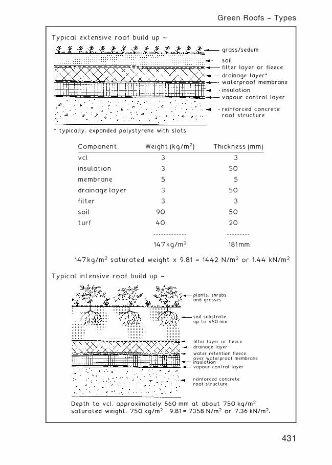
Typical extensive roof build up ~
grass/sedum
soil
filter layer or fleece
drainage layer*waterproof membrane
insulation
vapour control layer
reinforced concreteroof structure
* typically, expanded polystyrene with slots
147kg/m2 saturated weight x 9.81 = 1442 N/m2 or 1.44 kN/m2
Typical intensive roof build up ~
filter layer or fleecedrainage layer
water retention fleeceover waterproof membraneinsulationvapour control layer
reinforced concreteroof structure
Depth to vcl, approximately 560 mm at about 750 kg/m2
saturated weight. 750 kg/m2 × 9.81 = 7358 N/m2 or 7.36 kN/m2.
plants, shrubsand grasses
soil substrateup to 450 mm
Component Weight (kg/m2) Thickness (mm)
vcl 3 3
insulation 3 50
membrane 5 5
drainage layer 3 50
filter 3 3
soil 90 50
turf 40 20
------------- ---------
147kg/m2 181mm
431
Green Roofs -- Types
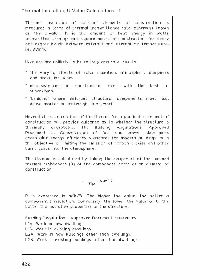
Thermal insulation of external elements of construction is
measured in terms of thermal transmittance rate, otherwise known
as the U-value. It is the amount of heat energy in watts
transmitted through one square metre of construction for every
one degree Kelvin between external and internal air temperature,
i.e. W/m2K.
U-values are unlikely to be entirely accurate, due to:
* the varying effects of solar radiation, atmospheric dampness
and prevailing winds.
* inconsistencies in construction, even with the best of
supervision.
* `bridging' where different structural components meet, e.g.
dense mortar in lightweight blockwork.
Nevertheless, calculation of the U-value for a particular element of
construction will provide guidance as to whether the structure is
thermally acceptable. The Building Regulations, Approved
Document L, Conservation of fuel and power, determines
acceptable energy efficiency standards for modern buildings, with
the objective of limiting the emission of carbon dioxide and other
burnt gases into the atmosphere.
The U-value is calculated by taking the reciprocal of the summed
thermal resistances (R) of the component parts of an element of
construction:
U ¼ 1
� R¼W=m
2K
R is expressed in m2K/W. The higher the value, the better a
component's insulation. Conversely, the lower the value of U, the
better the insulative properties of the structure.
Building Regulations, Approved Document references:
L1A, Work in new dwellings.
L1B, Work in existing dwellings.
L2A, Work in new buildings other than dwellings.
L2B, Work in existing buildings other than dwellings.
432
Thermal Insulation, U-Value Calculations---1
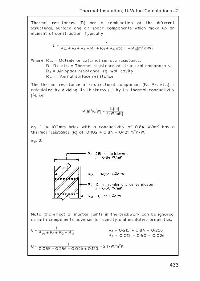
Thermal resistances (R) are a combination of the different
structural, surface and air space components which make up an
element of construction. Typically:
U =1
Rso + R1 + R2 + Ra + R3 + R4 etc . . . + Rsi(m2K=W)
Where: Rso = Outside or external surface resistance.
R1, R2, etc. = Thermal resistance of structural components.
Ra = Air space resistance, eg. wall cavity.
Rsi = Internal surface resistance.
The thermal resistance of a structural component (R1, R2, etc.) is
calculated by dividing its thickness (L) by its thermal conductivity
(�), i.e.
R(m2K=W) =L(m)
� (W=mK)
eg. 1. A 102mm brick with a conductivity of 0„84 W/mK has a
thermal resistance (R) of: 0„102 … 0„84 = 0„121 m2K/W.
eg. 2.
Note: the effect of mortar joints in the brickwork can be ignored,
as both components have similar density and insulative properties.
U =1
Rso + R1 + R2 + RsiR1 = 0„215 … 0„84 = 0„256
R2 = 0„013 … 0„50 = 0„026
U =1
0:055 + 0:256 + 0:026 + 0:123= 2:17W=m2K
433
Thermal Insulation, U-Value Calculations---2
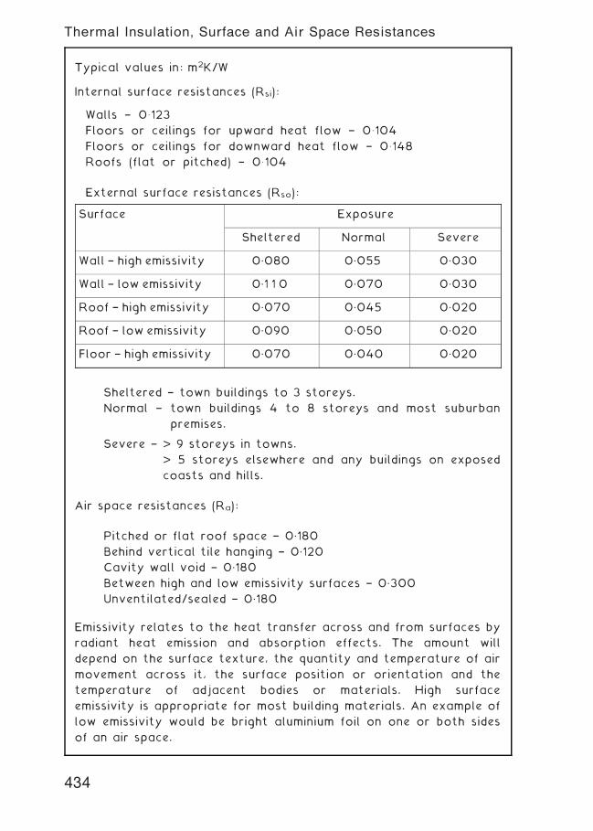
Typical values in: m2K/W
Internal surface resistances (Rsi):
Walls † 0� 123
Floors or ceilings for upward heat flow † 0� 104
Floors or ceilings for downward heat flow † 0� 148
Roofs (flat or pitched) † 0� 104
External surface resistances (Rso):
Sheltered † town buildings to 3 storeys.
Normal † town buildings 4 to 8 storeys and most suburban
premises.
Severe † > 9 storeys in towns.
> 5 storeys elsewhere and any buildings on exposed
coasts and hills.
Air space resistances (Ra):
Pitched or flat roof space † 0„180
Behind vertical tile hanging † 0„120
Cavity wall void † 0„180
Between high and low emissivity surfaces † 0„300
Unventilated/sealed † 0„180
Emissivity relates to the heat transfer across and from surfaces by
radiant heat emission and absorption effects. The amount will
depend on the surface texture, the quantity and temperature of air
movement across it, the surface position or orientation and the
temperature of adjacent bodies or materials. High surface
emissivity is appropriate for most building materials. An example of
low emissivity would be bright aluminium foil on one or both sides
of an air space.
Thermal Insulation, Surface and Air Space Resistances
Surface Exposure
Sheltered Normal Severe
Wall † high emissivity 0„080 0„055 0„030
Wall † low emissivity 0„1 1 0 0„070 0„030
Roof † high emissivity 0„070 0„045 0„020
Roof † low emissivity 0„090 0„050 0„020
Floor † high emissivity 0„070 0„040 0„020
434
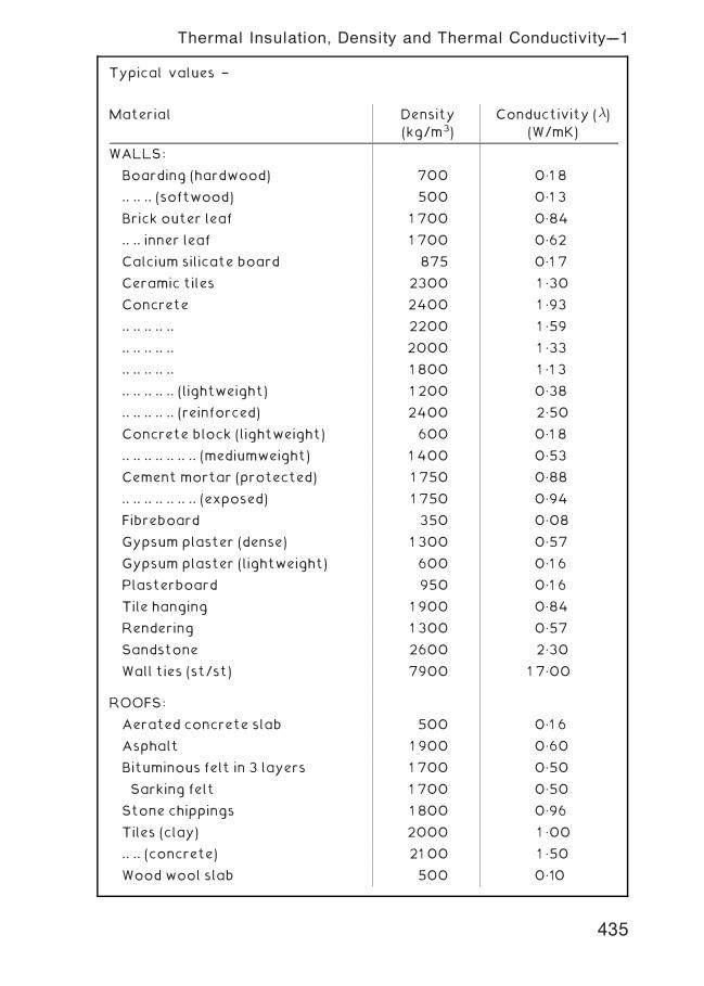
Typical values †
Material Density
(kg/m3)
Conductivity (�)(W/mK)
WALLS:
Boarding (hardwood) 700 0„1 8
.. .. .. (softwood) 500 0„1 3
Brick outer leaf 1 700 0„84
.. .. inner leaf 1 700 0„62
Calcium silicate board 875 0„1 7
Ceramic tiles 2300 1 „30
Concrete 2400 1 „93
.. .. .. .. .. 2200 1 „59
.. .. .. .. .. 2000 1 „33
.. .. .. .. .. 1 800 1 „1 3
.. .. .. .. .. (lightweight) 1 200 0„38
.. .. .. .. .. (reinforced) 2400 2„50
Concrete block (lightweight) 600 0„1 8
.. .. .. .. .. .. .. (mediumweight) 1 400 0„53
Cement mortar (protected) 1 750 0„88
.. .. .. .. .. .. .. (exposed) 1 750 0„94
Fibreboard 350 0„08
Gypsum plaster (dense) 1 300 0„57
Gypsum plaster (lightweight) 600 0„1 6
Plasterboard 950 0„1 6
Tile hanging 1 900 0„84
Rendering 1 300 0„57
Sandstone 2600 2„30
Wall ties (st/st) 7900 1 7„00
ROOFS:
Aerated concrete slab 500 0„1 6
Asphalt 1 900 0„60
Bituminous felt in 3 layers 1 700 0„50
Sarking felt 1 700 0„50
Stone chippings 1 800 0„96
Tiles (clay) 2000 1 „00
.. .. (concrete) 21 00 1 „50
Wood wool slab 500 0„10
Thermal Insulation, Density and Thermal Conductivity---1
435
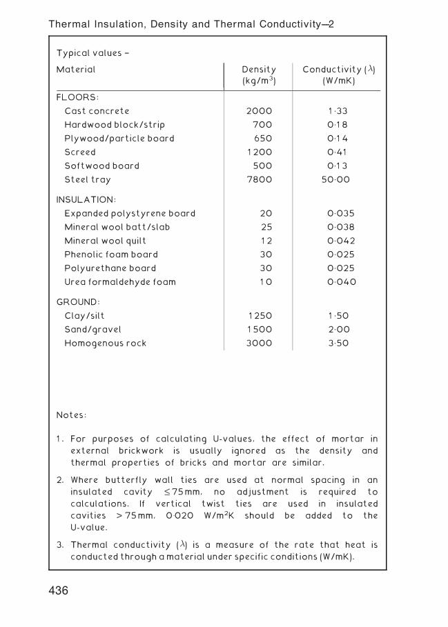
Notes:
1 . For purposes of calculating U-values, the effect of mortar in
external brickwork is usually ignored as the density and
thermal properties of bricks and mortar are similar.
2. Where butterfly wall ties are used at normal spacing in an
insulated cavity £ 75mm, no adjustment is required to
calculations. If vertical twist ties are used in insulated
cavities > 75mm, 0�020 W/m2K should be added to the
U-value.
3. Thermal conductivity (�) is a measure of the rate that heat is
conducted through amaterial under specific conditions (W/mK).
Typical values †
Material Density
(kg/m3)
Conductivity (�)(W/mK)
FLOORS:
Cast concrete 2000 1 „33
Hardwood block/strip 700 0„1 8
Plywood/particle board 650 0„1 4
Screed 1 200 0„41
Softwood board 500 0„1 3
Steel tray 7800 50„00
INSULATION:
Expanded polystyrene board 20 0„035
Mineral wool batt/slab 25 0„038
Mineral wool quilt 1 2 0„042
Phenolic foam board 30 0„025
Polyurethane board 30 0„025
Urea formaldehyde foam 1 0 0„040
GROUND:
Clay/silt 1 250 1 „50
Sand/gravel 1 500 2„00
Homogenous rock 3000 3„50
436
Thermal Insulation, Density and Thermal Conductivity---2
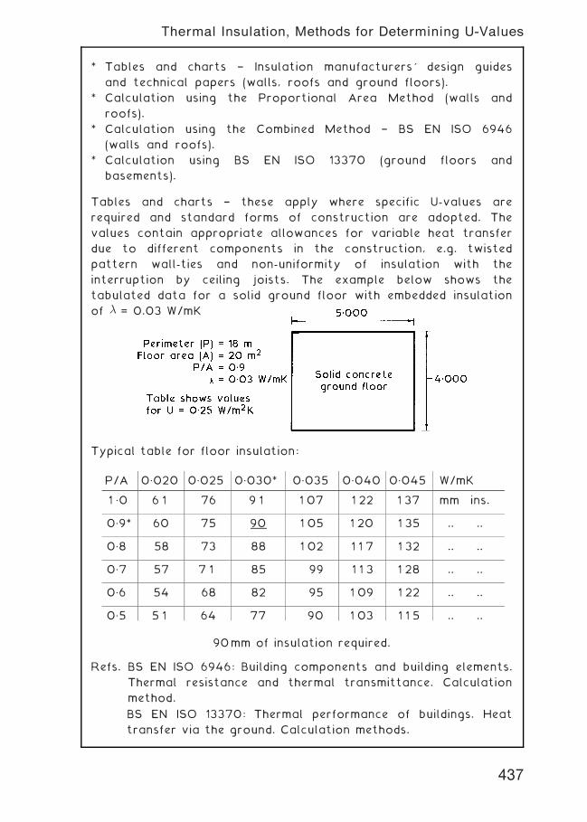
* Tables and charts † Insulation manufacturers' design guides
and technical papers (walls, roofs and ground floors).
* Calculation using the Proportional Area Method (walls and
roofs).
* Calculation using the Combined Method † BS EN ISO 6946
(walls and roofs).
* Calculation using BS EN ISO 13370 (ground floors and
basements).
Tables and charts † these apply where specific U-values are
required and standard forms of construction are adopted. The
values contain appropriate allowances for variable heat transfer
due to different components in the construction, e.g. twisted
pattern wall-ties and non-uniformity of insulation with the
interruption by ceiling joists. The example below shows the
tabulated data for a solid ground floor with embedded insulation
of � = 0.03 W/mK
Typical table for floor insulation:
90mm of insulation required.
Refs. BS EN ISO 6946: Building components and building elements.
Thermal resistance and thermal transmittance. Calculation
method.
BS EN ISO 13370: Thermal performance of buildings. Heat
transfer via the ground. Calculation methods.
P/A 0„020 0„025 0„030* 0„035 0„040 0„045 W/mK
1 „0 6 1 76 9 1 1 07 1 22 1 37 mm ins.
0„9* 60 75 90 1 05 1 20 1 35 .. ..
0„8 58 73 88 1 02 1 1 7 1 32 .. ..
0„7 57 7 1 85 99 1 1 3 1 28 .. ..
0„6 54 68 82 95 1 09 1 22 .. ..
0„5 5 1 64 77 90 1 03 1 1 5 .. ..
437
Thermal Insulation, Methods for Determining U-Values
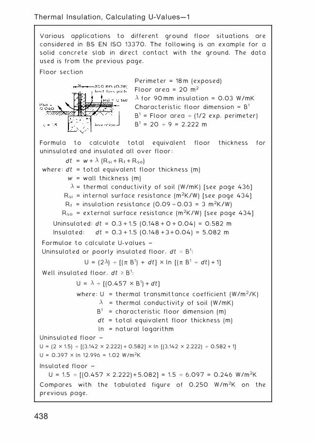
Various applications to different ground floor situations are
considered in BS EN ISO 13370. The following is an example for a
solid concrete slab in direct contact with the ground. The data
used is from the previous page.
Floor section
Perimeter = 18m (exposed)
Floor area = 20 m2
� for 90mm insulation = 0.03 W/mK
Characteristic floor dimension = B1
B1 = Floor area … (1/2 exp. perimeter)
B1 = 20 … 9 = 2.222 m
Formula to calculate total equivalent floor thickness for
uninsulated and insulated all over floor:
dt = w+ � (Rsi + Rf + Rso)
where: dt = total equivalent floor thickness (m)
w = wall thickness (m)
� = thermal conductivity of soil (W/mK) [see page 436]
Rsi = internal surface resistance (m2K/W) [see page 434]
Rf = insulation resistance (0.09 …0.03 = 3 m2K/W)
Rso = external surface resistance (m2K/W) [see page 434]
Uninsulated: dt = 0.3 + 1.5 (0.148 +0+0.04) = 0.582 m
Insulated: dt = 0.3 + 1.5 (0.148 +3+0.04) = 5.082 m
Formulae to calculate U-values ~
Uninsulated or poorly insulated floor, dt < B1:
U = (2�) … [(p B1) + dt] � ln [(p B1 … dt) + 1]
Well insulated floor, dt ‡ B1:
U = � … [(0.457 � B1) + dt]
where: U = thermal transmittance coefficient (W/m2/K)
� = thermal conductivity of soil (W/mK)
B1 = characteristic floor dimension (m)
dt = total equivalent floor thickness (m)
ln = natural logarithm
Uninsulated floor ~
U = (2 � 1.5) … [(3.142 � 2.222) + 0.582] � ln [(3.142 � 2.222) … 0.582 + 1]
U = 0.397 � ln 12.996 = 1.02 W/m2K
Insulated floor ~
U = 1.5 … [(0.457 � 2.222)+5.082] = 1.5 … 6.097 = 0.246 W/m2K
Compares with the tabulated figure of 0.250 W/m2K on the
previous page.
438
Thermal Insulation, Calculating U-Values---1
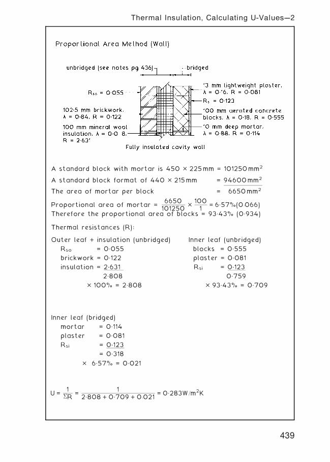
A standard block with mortar is 450 � 225mm = 101250mm2
A standard block format of 440 � 215mm = 94600mm2
The area of mortar per block = 6650mm2
Proportional area of mortar =6650101250 �
1001
= 6„57%(0:066)
Therefore the proportional area of blocks = 93„43% (0„934)
Thermal resistances (R):
Outer leaf + insulation (unbridged) Inner leaf (unbridged)
Rso = 0„055 blocks = 0„555
brickwork = 0„122 plaster = 0„081
insulation = 2.631 Rsi = 0.123
2„808 0„759
� 100% = 2„808 � 93„43% = 0„709
Inner leaf (bridged)
mortar = 0„114
plaster = 0„081
Rsi = 0.123
= 0„318
� 6„57% = 0„021
U =1
�R=
12„808 + 0„709 + 0:021
= 0„283W=m2K
439
Thermal Insulation, Calculating U-Values---2
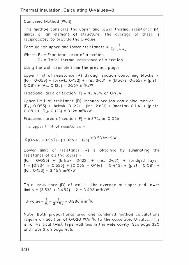
Combined Method (Wall)
This method considers the upper and lower thermal resistance (R)
limits of an element of structure. The average of these is
reciprocated to provide the U-value.
Formula for upper and lower resistances =1
�(Fx… Rx)
Where: Fx = Fractional area of a section
Rx = Total thermal resistance of a section
Using the wall example from the previous page:
Upper limit of resistance (R) through section containing blocks †
(Rso, 0„055) + (brkwk, 0„122) + (ins, 2„631) + (blocks, 0„555) + (plstr,
0„081) + (Rsi, 0„123) = 3„567 m2K/W
Fractional area of section (F) = 93„43% or 0„934
Upper limit of resistance (R) through section containing mortar †
(Rso 0„055) + (brkwk, 0„122) + (ins, 2„631) + (mortar, 0„114) + (plstr,
0„081) + (Rsi, 0„123) = 3„126 m2K/W
Fractional area of section (F) = 6„57% or 0„066
The upper limit of resistance =
1� (0„943 … 3„567) + (0„066 … 3„126)
= 3„533m2K=W
Lower limit of resistance (R) is obtained by summating the
resistance of all the layers †
(Rso, 0„055) + (brkwk, 0„122) + (ins, 2„631) + (bridged layer,
1 … [0„934 … 0„555] + [0„066 … 0„114] = 0„442) + (plstr, 0„081) +(Rsi, 0„123) = 3„454 m2K/W
Total resistance (R) of wall is the average of upper and lower
limits = (3„533 + 3„454) … 2 = 3„493 m2K/W
U-value =1R
=1
3„493= 0„286 W=m2K
Note: Both proportional area and combined method calculations
require an addition of 0„020 W/m2K to the calculated U-value. This
is for vertical twist type wall ties in the wide cavity. See page 320
and note 2 on page 436.
440
Thermal Insulation, Calculating U-Values---3
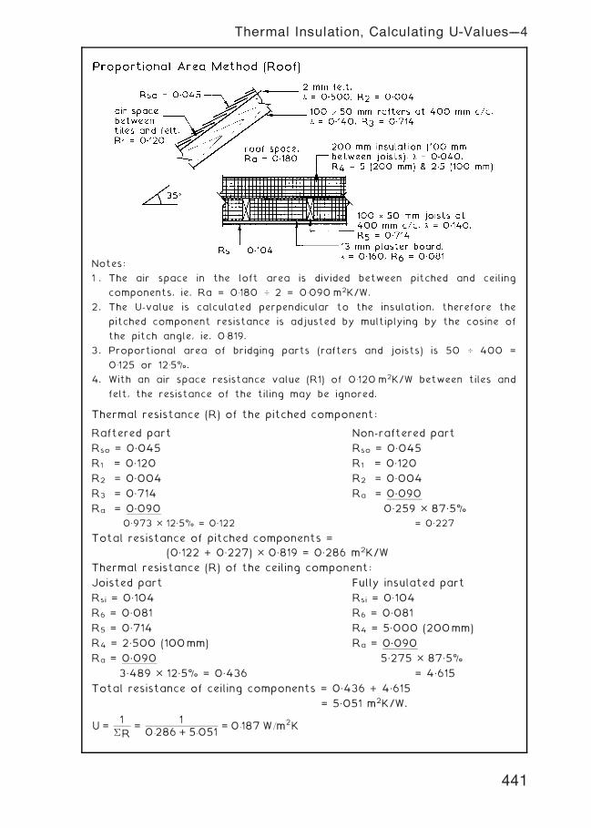
Notes:
1 . The air space in the loft area is divided between pitched and ceiling
components, ie. Ra = 0�180 � 2 = 0�090 m2K/W.
2. The U-value is calculated perpendicular to the insulation, therefore the
pitched component resistance is adjusted by multiplying by the cosine of
the pitch angle, ie. 0�819.
3. Proportional area of bridging parts (rafters and joists) is 50 � 400 =
0�125 or 12�5%.
4. With an air space resistance value (R1) of 0�120 m2K/W between tiles and
felt, the resistance of the tiling may be ignored.
Thermal resistance (R) of the pitched component:
Raftered part Non-raftered part
Rso = 0„045 Rso = 0„045
R1 = 0„120 R1 = 0„120
R2 = 0„004 R2 = 0„004
R3 = 0„714 Ra = 0.090
Ra = 0.090 0„259 � 87„5%
0„973 � 12„5% = 0„122 = 0„227
Total resistance of pitched components =
(0„122 + 0„227) � 0„819 = 0„286 m2K/W
Thermal resistance (R) of the ceiling component:
Joisted part Fully insulated part
Rsi = 0„104 Rsi = 0„104
R6 = 0„081 R6 = 0„081
R5 = 0„714 R4 = 5„000 (200mm)
R4 = 2„500 (100mm) Ra = 0.090
Ra = 0.090 5„275 � 87„5%
3„489 � 12„5% = 0„436 = 4„615
Total resistance of ceiling components = 0„436 + 4„615
= 5„051 m2K/W.
U =1
�R=
10:286 + 5:051
= 0:187 W=m2K
441
Thermal Insulation, Calculating U-Values---4
Standard Assessment Procedure ~ the Approved Document to Part
L of the Building Regulations emphasises the importance of
quantifying the energy costs of running homes. For this purpose it
uses the Government's Standard Assessment Procedure (SAP). SAP
has a numerical scale of 1 to 100, although it can exceed 100 if a
dwelling is a net energy exporter. It takes into account the
effectiveness of a building's fabric relative to insulation and
standard of construction. It also appraises the energy efficiency of
fuel consuming installations such as ventilation, hot water, heating
and lighting. Incidentals like solar gain also feature in the
calculations.
As part of the Building Regulations approval procedure, energy
rating (SAP) calculations are submitted to the local building
control authority. SAP ratings are also required to provide
prospective home purchasers or tenants with an indication of the
expected fuel costs for hot water and heating. This information is
documented and included with the property conveyance. The SAP
calculation involves combining data from tables, work sheets and
formulae. Guidance is found in Approved Document L, or by
application of certified SAP computer software programmes.
As a guide, housing built to 1995 energy standards can be expected
to have a SAP rating of around 80. That built to 2002 energy
standards will have a SAP expectation of about 90. Current
quality construction standards should rate dwellings close to 100.
Ref. Standard Assessment Procedure for Energy Rating of
Dwellings. The Stationery Office.
Air Permeability ~ air tightness in the construction of dwellings is
an important quality control objective. Compliance is achieved by
attention to detail at construction interfaces, e.g. by silicone
sealing built-in joists to blockwork inner leafs and door and window
frames to masonry surrounds; draft proofing sashes, doors and loft
hatches. Dwellings failing to comply with these measures are
penalised in SAP calculations.
Compliance with the Building Regulations Part L Robust Details is
an acceptable standard of construction. Alternatively, a certificate
must be obtained to show pre-completion testing satisfying air
permeability of less than 10 m3/h per m2 envelope area at 50
Pascals (Pa or N/m2) pressure.
Ref. Limiting thermal bridging and air leakage: Robust construction
details for dwellings and similar buildings. The Stationery Office.
442
Thermal Insulation Energy Efficiency of New Dwellings
Domestic buildings (England and Wales) ~
The area weighted average U-value for an element of construction
depends on the individual U-values of all components and the area
they occupy within that element. E.g. The part of a wall with a meter
cupboard built in will have less resistance to thermal transmittance
than the rest of the wall (max. U-value at cupboard, 0.45).
Note: Maximum area of windows, doors, rooflights and roof
windows, 25% of the total floor area.
An alternative to the area weighted average U-value for
windows, etc., may be a window energy rating of not less
than minus 30.
Energy source ~ gas or oil fired central heating boiler with a
minimum SEDBUK efficiency rating of 86% (band rating A or B).
There are transitional and exceptional circumstances that permit
lower band rated boilers. Where this occurs, the construction of
the building envelope should compensate with very low U-values.
SEDBUK = Seasonal Efficiency of a Domestic Boiler in the United
Kingdom. SEDBUK values are defined in the Government's Standard
Assessment Procedure for Energy Rating of Dwellings. There is also
a SEDBUK website, www.sedbuk.com.
Note: SEDBUK band A = > 90% efficiency
band B = 86†90% ..
band C = 82†86% ..
band D = 78†82% ..
Element of
construction
Limiting area
weighted ave. U-value (W/m2K)
Limiting individual
component U-value
Roof 0.25 0.35
Wall 0.35 0.70
Floor 0.25 0.70
Windows, doors, rooflights
and roof windows
2.20 3.30
Element of construction U-value targets (W/m2K)
Pitched roof (insulation between rafters) 0.15
Pitched roof (insulation between joists) 0.15
Flat roof 0.15
Wall 0.28
Floor 0.20
Windows, doors, rooflights
and roof windows
1.80 (area weighted ave.)
443
Thermal Insulation, Elements of Construction
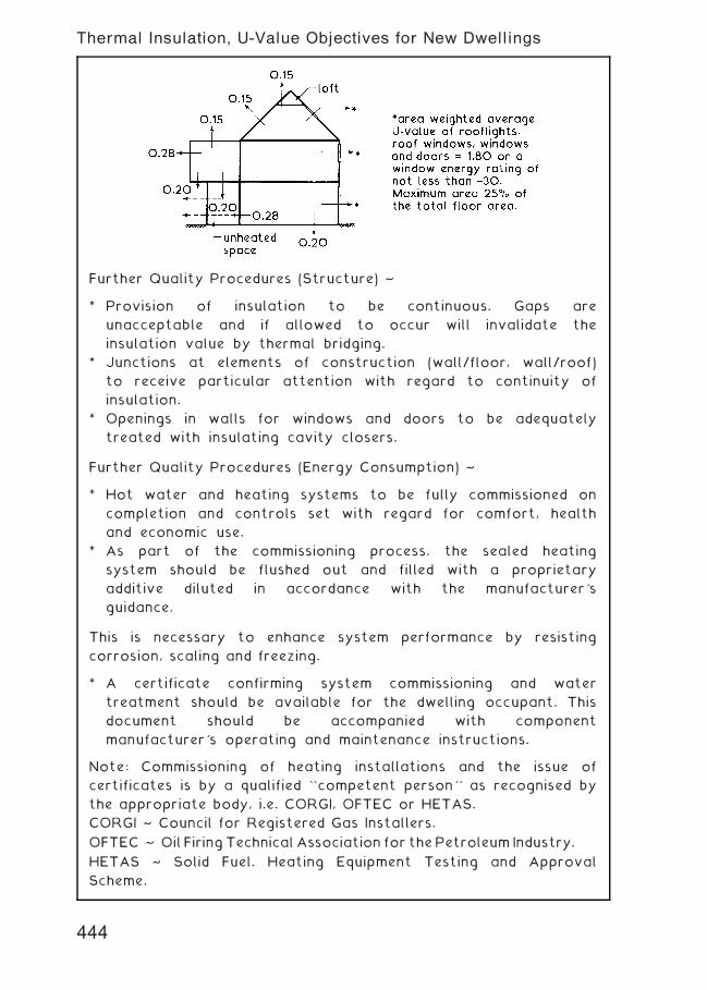
Further Quality Procedures (Structure) ~
* Provision of insulation to be continuous. Gaps are
unacceptable and if allowed to occur will invalidate the
insulation value by thermal bridging.
* Junctions at elements of construction (wall/floor, wall/roof)
to receive particular attention with regard to continuity of
insulation.
* Openings in walls for windows and doors to be adequately
treated with insulating cavity closers.
Further Quality Procedures (Energy Consumption) ~
* Hot water and heating systems to be fully commissioned on
completion and controls set with regard for comfort, health
and economic use.
* As part of the commissioning process, the sealed heating
system should be flushed out and filled with a proprietary
additive diluted in accordance with the manufacturer's
guidance.
This is necessary to enhance system performance by resisting
corrosion, scaling and freezing.
* A certificate confirming system commissioning and water
treatment should be available for the dwelling occupant. This
document should be accompanied with component
manufacturer's operating and maintenance instructions.
Note: Commissioning of heating installations and the issue of
certificates is by a qualified ``competent person'' as recognised by
the appropriate body, i.e. CORGI, OFTEC or HETAS.
CORGI ~ Council for Registered Gas Installers.
OFTEC ~ Oil FiringTechnical Association for thePetroleum Industry.
HETAS ~ Solid Fuel. Heating Equipment Testing and Approval
Scheme.
444
Thermal Insulation, U-Value Objectives for New Dwellings
European Window Energy Rating Scheme (EWERS) ~ an alternative
to U-values for measuring the thermal efficiency of windows.
U-values form part of the assessment, in addition to factors for
solar heat gain and air leakage. In the UK, testing and labelling of
window manufacturer's products is promoted by the British
Fenestration Rating Council (BFRC). The scheme uses a computer
to simulate energy movement over a year through a standard
window of 1.480 � 1.230m containing a central mullion and opening
sash to one side.
Data is expressed on a scale from A†G in units of kWh/m2/year.
A > zero
B †10 to 0
C †20 to †10
D †30 to †20
E †50 to †30
F †70 to †50
G < †70
By formula, rating = (218.6 �g value) † 68.5 (U-value � L value)
Where: g value = factor measuring
effectiveness of solar heat block
expressed between 0 and 1. For
comparison:
0.48 (no curtains)
0.43 (curtains open)
0.17 (curtains closed)
U value = weighted average
transmittance coefficient
L value = air leakage factor
From the label shown opposite:
Rating = (218„6 � 0„5)
† 68„5 (1„8 + 0„10)
= 109„3 † 130„15
= †20„85 i.e. †21
Typical format of a window
energy rating label ~
ABCJoinery Ltd.
Window ref. XYZ 123
445
Thermal Insulation, Window Energy Rating
The Government's Standard Assessment Procedure (SAP) for
energy rating dwellings includes a facility to calculate carbon
dioxide (CO2) emissions in kilograms or tonnes per year. The
established carbon index method allows for adjustment to dwelling
floor area to obtain a carbon factor (CF):
CF = CO2 … (total floor area + 45)
The carbon index (CI) = 17„7 † (9 log. CF)
Note: log. = logarithm to the base 10.
e.g. A dwelling of total floor area 125m2, with CO2 emissions of
2000 kg/yr.
CF = 2000 … (125 + 45) = 11„76
CI = 17„7 † (9 log. 11„76) = 8„06
The carbon index (CI) is expressed on a scale of 0 to 10. The higher
the number the better. Every new dwelling should have a CI value
of a least 8.
Approved Document L to the Building Regulations includes the
Dwelling Carbon Emissions Rate (DER) as another means for
assessing carbon discharge. The DER is compared by calculation to
a Target Carbon Emissions Rate (TER), based on data for type of
lighting, floor area, building shape and choice of fuel.
The DER is derived primarily by appraising the potential CO2
emission from a dwelling relative to the consumption of fuel
(directly or indirectly) in hot water, heating, lighting, cooling (if
fitted), fans and pumps.
DER £ TER
Buildings account for about half of the UK's carbon emissions.
Therefore, there are considerable possibilities for energy savings
and reductions in atmospheric pollution.
446
Thermal Insulation, Carbon Emissions
In new buildings and those subject to alterations, the objective is
to optimise the use of fuel and power to minimise emission of
carbon dioxide and other burnt fuel gases into the atmosphere.
This applies principally to the installation of hot water, heating,
lighting, ventilation and air conditioning systems. Pipes, ducting,
storage vessels and other energy consuming plant should be
insulated to limit heat losses. The fabric or external envelope of a
building is constructed with regard to limiting heat losses through
the structure and to regulate solar gains.
Approved Document L2 of the Building Regulations is not
prescriptive. It sets out a series of objectives relating to
achievement of a satisfactory carbon emission standard. A number
of other technical references and approvals are cross referenced in
the Approved Document and these provide a significant degree of
design flexibility in achieving the objectives.
Energy efficiency of buildings other than dwellings is determined by
applying a series of procedures modelled on a notional building of
the same size and shape as the proposed building. The performance
standards used for the notional building are similar to the 2002
edition of Approved Document L2. Therefore the proposed or
actual building must be seen to be a significant improvement in
terms of reduced carbon emissions by calculation. Improvements
can be achieved in a number of ways, including the following:
• Limit the area or number of rooflights, windows and other openings.• Improve the U-values of the external envelope. The limiting
values are shown on the next page.
• Improve the airtightness of the building from the poorest
acceptable air permeability of 10 m3/hour/m2 of external
envelope at 50Pa pressure.• Improve the heating system efficiency by installing thermostatic
controls, zone controls, optimum time controls, etc. Fully
insulate pipes and equipment.
• Use of high efficacy lighting fittings, automated controls, low
voltage equipment, etc.
• Apply heat recovery systems to ventilation and air
conditioning systems. Insulate ducting.
• Install a building energy management system to monitor and
regulate use of heating and air conditioning plant.
• Limit overheating of the building with solar controls and
appropriate glazing systems.
• Ensure that the quality of construction provides for continuity
of insulation in the external envelope.
• Establish a commissioning and plant maintenance procedure.
Provide a log-book to document all repairs, replacements and
routine inspections.
447
Thermal Insulation, Buildings Other Than Dwellings---1
Buildings Other Than Dwellings (England and Wales) ~
Notes:
• For display windows separate consideration applies. See
Section 5 in A.D., L2A.
• The poorest acceptable thermal transmittance values provide
some flexibility for design, allowing a trade off against other
thermally beneficial features such as energy recovery systems.
• The minimum U-value standard is set with regard to minimise
the risk of condensation.
• The concept of area weighted values is explained on page 443.
• Elements will normally be expected to have much better
insulation than the limiting U-values. Suitable objectives or
targets could be as shown for domestic buildings.
Further requirements for the building fabric ~
Insulation continuity ~ this requirement is for a fully insulated
external envelope with no air gaps in the fabric. Vulnerable places
are at junctions between elements of construction, e.g. wall to
roof, and around openings such as door and window reveals.
Conformity can be shown by producing evidence in the form of a
report produced for the local authority building control department
by an accredited surveyor. The report must indicate that:
* the approved design specification and construction practice
are to an acceptable standard of conformity, OR
* a thermographic survey shows continuity of insulation over
the external envelope. This is essential when it is impractical
to fully inspect the work in progress.
Air tightness ~ requires that there is no air infiltration through
gaps in construction and at the intersection of elements.
Permeability of air is tested by using portable fans of capacity to
suit the building volume. Smoke capsules in conjunction with air
pressurisation will provide a visual indication of air leakage paths.
Element of
construction
Limiting area
weighted ave.
U-value (W/m2K)
Limiting individual
component
U-value
Roof 0.25 0.35
Wall 0.35 0.45
Floor 0.25 0.45
Windows, doors roof-lights
and roof windows
2.20 3.30
Curtain wall (full facade) 1.60 2.50
Large and vehicle
access doors
1.50 4.00
448
Thermal Insulation, Buildings Other Than Dwellings---2
Thermal Insulation ~ this is required within the roof of all dwellings
in the UK. It is necessary to create a comfortable internal
environment, to reduce the risk of condensation and to economise
in fuel consumption costs.
To satisfy these objectives, insulation may be placed between and
over the ceiling joists as shown below to produce a cold roof void.
Alternatively, the insulation can be located above the rafters as
shown on page 404. Insulation above the rafters creates a warm
roof void and space within the roof structure that may be useful
for habitable accommodation.
449
Thermal Insulation, Dwelling Roof Space
Thermal insulation to Walls ~ the minimum performance standards
for exposed walls set out in Approved Document L to meet the
requirements of Part L of the Building Regulations can be achieved
in several ways (see pages 439 and 440). The usual methods
require careful specification, detail and construction of the wall
fabric, insulating material(s) and/or applied finishes.
Typical Examples of existing construction that would require
upgrading to satisfy contemporary UK standards ~
450
Thermal Insulation -- External Walls
Typical examples of contemporary construction practice that
achieve a thermal transmittance or U-value below 0„30 W/m2K ~
120 mm mineralwool cavity batts 100 mm lightweight
concrete block innerleaf
13 mm lightweightplaster
102.5 mm externalbrick outer leaf
75 mm mineralwool cavity batts
lightweight concreteblocks, density460 kg/m3
9.5 mm plasterboardon dabs
T
102.5 mm externalbrick outer leaf
50 mm wide cavity
40 mm mineral woolcavity batts
mineral wool batts
T
VCL and 12.5 mmplasterboard
breather membraneand sheathingboard
102.5 mm externalbrick outer leaf
TIMBER FRAME PART CAVITY FILL, T = 100 mm U = 0.26 W/m2K
T = 120 mm U = 0.24 W/m2K
T = 140 mm U = 0.21 W/m2K
FULL FILL CAVITY WALL, Block density 750 kg/m3 U = 0.25 W/m2K
Block density 600 kg/m3 U = 0.24 W/m2K
Block density 475 kg/m3 U = 0.23 W/m2K
FULL FILL CAVITY WALL,T = 150 mm U = 0.26 W/m2KT = 200 mm U = 0.24 W/m2K
T = 125 mm U = 0.28 W/m2K
Note: Mineral wool insulating batts have a typical thermal
conductivity (�) value of 0„038 W/mK.
451
Thermal Insulation -- External Walls
Thermal or Cold Bridging ~ this is heat loss and possible
condensation, occurring mainly around window and door openings
and at the junction between ground floor and wall. Other
opportunities for thermal bridging occur where uniform
construction is interrupted by unspecified components, e.g.
occasional use of bricks and/or tile slips to make good gaps in
thermal block inner leaf construction.
NB. This practice was quite common, but no longer acceptable by
current legislative standards in the UK.
Prime areas for concern †
*Note: Cavity should extend down at least 225 mm below the level of thelowest dpc (AD, C: Section 5).
GROUND FLOOR & WALL
dpc
cavity insulation incomplete,possibly caused by mortardroppings building up and bridgingthe lower part of the cavity*
hollow steellintelandincompletecavityinsulation
heat lossthroughuninsulated wall
incompletecavityinsulation
WINDOW/DOOR HEAD
WINDOW/DOOR JAMBWINDOW SILL
452
Thermal Bridging
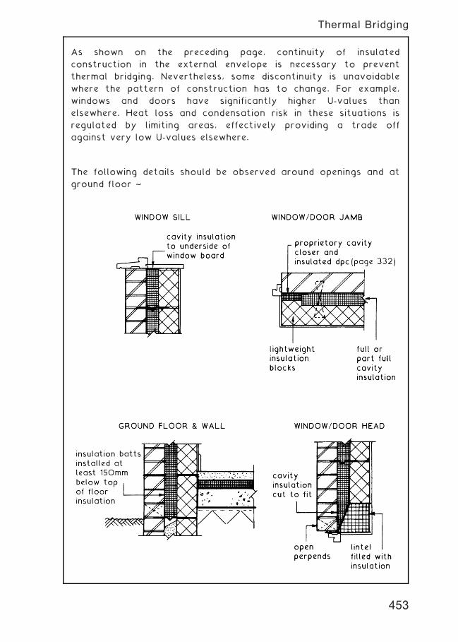
As shown on the preceding page, continuity of insulated
construction in the external envelope is necessary to prevent
thermal bridging. Nevertheless, some discontinuity is unavoidable
where the pattern of construction has to change. For example,
windows and doors have significantly higher U-values than
elsewhere. Heat loss and condensation risk in these situations is
regulated by limiting areas, effectively providing a trade off
against very low U-values elsewhere.
The following details should be observed around openings and at
ground floor ~
453
Thermal Bridging
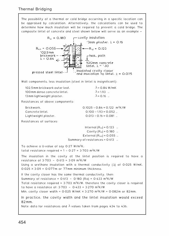
The possibility of a thermal or cold bridge occurring in a specific location can
be appraised by calculation. Alternatively, the calculations can be used to
determine how much insulation will be required to prevent a cold bridge. The
composite lintel of concrete and steel shown below will serve as an example ~
Wall components, less insulation (steel in lintel is insignificant):
Resistances of above components:
Resistances of surfaces:
To achieve a U-value of say 0„27 W/m2K,
total resistance required = 1 … 0„27 = 3„703 m2K/W
The insulation in the cavity at the lintel position is required to have a
resistance of 3„703 † 0„613 = 3„09 m2K/W
Using a urethane insulation with a thermal conductivity (�) of 0„025 W/mK,
0„025 � 3„09 = 0„077m or 77mm minimum thickness.
If the cavity closer has the same thermal conductivity, then:
Summary of resistance = 0„613 † 0„180 (Ra) = 0„433 m2K/W
Total resistance required = 3„703 m2K/W, therefore the cavity closer is required
to have a resistance of: 3„703 † 0„433 = 3„270 m2K/W
Min. cavity closer width = 0„025 W/mK � 3„270 m2K/W = 0„082m or 82mm.
In practice, the cavity width and the lintel insulation would exceed
82mm.
Note: data for resistances and � values taken from pages 434 to 436.
102.5mm brickwork outer leaf, � = 0.84 W/mK
100mm dense concrete lintel, � = 1.93 ..
13mm lightweight plaster, � = 0.16 ..
Brickwork, 0.1025 … 0.84 = 0.122 m2K/W
Concrete lintel, 0.100 … 1.93 = 0.052 ..
Lightweight plaster, 0.013 … 0.16 = 0.081 ..
Internal (Rsi) = 0.123 ..
Cavity (Ra) = 0.180 ..
External (Rso) = 0.055 ..
Summary of resistances = 0„613 ..
454
Thermal Bridging
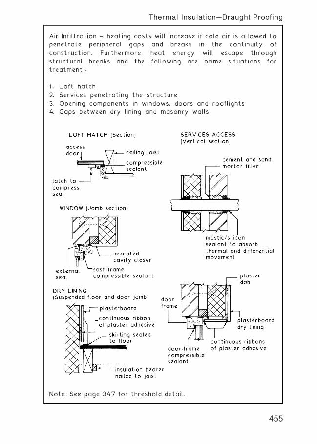
Air Infiltration ~ heating costs will increase if cold air is allowed to
penetrate peripheral gaps and breaks in the continuity of
construction. Furthermore, heat energy will escape through
structural breaks and the following are prime situations for
treatment:-
1 . Loft hatch
2. Services penetrating the structure
3. Opening components in windows, doors and rooflights
4. Gaps between dry lining and masonry walls
Note: See page 347 for threshold detail.
455
Thermal Insulation---Draught Proofing
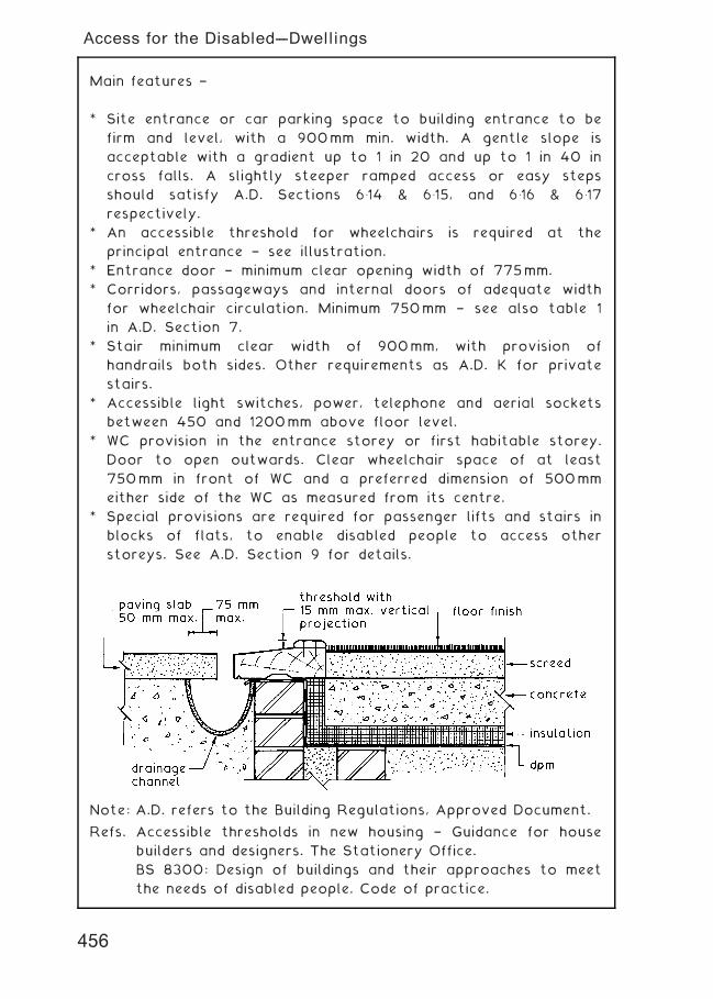
Main features †
* Site entrance or car parking space to building entrance to be
firm and level, with a 900mm min. width. A gentle slope is
acceptable with a gradient up to 1 in 20 and up to 1 in 40 in
cross falls. A slightly steeper ramped access or easy steps
should satisfy A.D. Sections 6�14 & 6�15, and 6�16 & 6�17
respectively.
* An accessible threshold for wheelchairs is required at the
principal entrance † see illustration.
* Entrance door † minimum clear opening width of 775mm.
* Corridors, passageways and internal doors of adequate width
for wheelchair circulation. Minimum 750mm † see also table 1
in A.D. Section 7.
* Stair minimum clear width of 900mm, with provision of
handrails both sides. Other requirements as A.D. K for private
stairs.
* Accessible light switches, power, telephone and aerial sockets
between 450 and 1200mm above floor level.
* WC provision in the entrance storey or first habitable storey.
Door to open outwards. Clear wheelchair space of at least
750mm in front of WC and a preferred dimension of 500mm
either side of the WC as measured from its centre.
* Special provisions are required for passenger lifts and stairs in
blocks of flats, to enable disabled people to access other
storeys. See A.D. Section 9 for details.
Note: A.D. refers to the Building Regulations, Approved Document.
Refs. Accessible thresholds in new housing † Guidance for house
builders and designers. The Stationery Office.
BS 8300: Design of buildings and their approaches to meet
the needs of disabled people. Code of practice.
Access for the Disabled---Dwellings
456
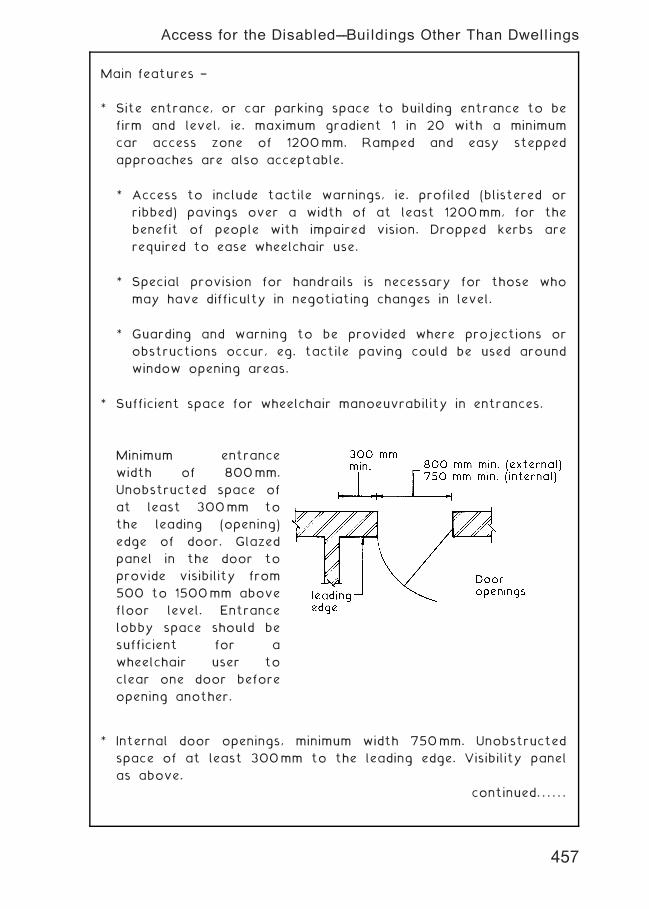
Main features †
* Site entrance, or car parking space to building entrance to be
firm and level, ie. maximum gradient 1 in 20 with a minimum
car access zone of 1200mm. Ramped and easy stepped
approaches are also acceptable.
* Access to include tactile warnings, ie. profiled (blistered or
ribbed) pavings over a width of at least 1200mm, for the
benefit of people with impaired vision. Dropped kerbs are
required to ease wheelchair use.
* Special provision for handrails is necessary for those who
may have difficulty in negotiating changes in level.
* Guarding and warning to be provided where projections or
obstructions occur, eg. tactile paving could be used around
window opening areas.
* Sufficient space for wheelchair manoeuvrability in entrances.
Minimum entrance
width of 800mm.
Unobstructed space of
at least 300mm to
the leading (opening)
edge of door. Glazed
panel in the door to
provide visibility from
500 to 1500mm above
floor level. Entrance
lobby space should be
sufficient for a
wheelchair user to
clear one door before
opening another.
* Internal door openings, minimum width 750mm. Unobstructed
space of at least 300mm to the leading edge. Visibility panel
as above.
continued. . . . . .
457
Access for the Disabled---Buildings Other Than Dwellings
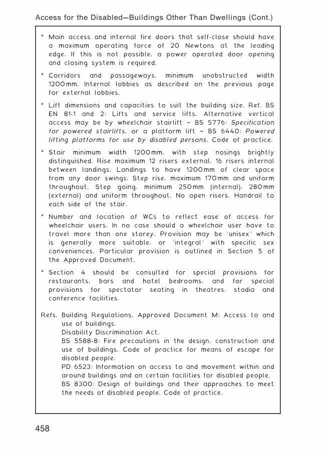
* Main access and internal fire doors that self-close should have
a maximum operating force of 20 Newtons at the leading
edge. If this is not possible, a power operated door opening
and closing system is required.
* Corridors and passageways, minimum unobstructed width
1200mm. Internal lobbies as described on the previous page
for external lobbies.
* Lift dimensions and capacities to suit the building size. Ref. BS
EN 81-1 and 2: Lifts and service lifts. Alternative vertical
access may be by wheelchair stairlift † BS 5776: Specification
for powered stairlifts, or a platform lift † BS 6440: Powered
lifting platforms for use by disabled persons. Code of practice.
* Stair minimum width 1200mm, with step nosings brightly
distinguished. Rise maximum 12 risers external, 16 risers internal
between landings. Landings to have 1200mm of clear space
from any door swings. Step rise, maximum 170mm and uniform
throughout. Step going, minimum 250mm (internal), 280mm
(external) and uniform throughout. No open risers. Handrail to
each side of the stair.
* Number and location of WCs to reflect ease of access for
wheelchair users. In no case should a wheelchair user have to
travel more than one storey. Provision may be `unisex' which
is generally more suitable, or `integral' with specific sex
conveniences. Particular provision is outlined in Section 5 of
the Approved Document.
* Section 4 should be consulted for special provisions for
restaurants, bars and hotel bedrooms, and for special
provisions for spectator seating in theatres, stadia and
conference facilities.
Refs. Building Regulations, Approved Document M: Access to and
use of buildings.
Disability Discrimination Act.
BS 5588-8: Fire precautions in the design, construction and
use of buildings. Code of practice for means of escape for
disabled people.
PD 6523: Information on access to and movement within and
around buildings and on certain facilities for disabled people.
BS 8300: Design of buildings and their approaches to meet
the needs of disabled people. Code of practice.
Access for the Disabled---Buildings Other Than Dwellings (Cont.)
458
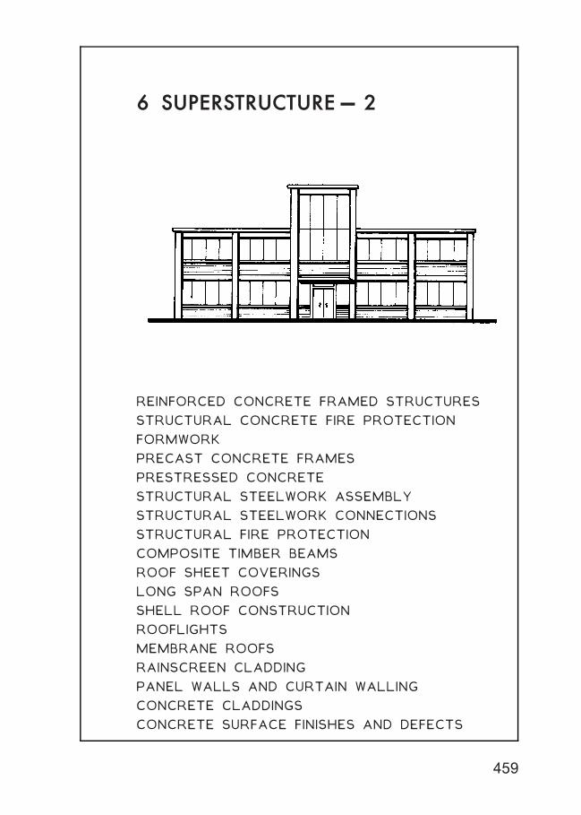
6 SUPERSTRUCTURE† 2
REINFORCED CONCRETE FRAMED STRUCTURES
STRUCTURAL CONCRETE FIRE PROTECTION
FORMWORK
PRECAST CONCRETE FRAMES
PRESTRESSED CONCRETE
STRUCTURAL STEELWORK ASSEMBLY
STRUCTURAL STEELWORK CONNECTIONS
STRUCTURAL FIRE PROTECTION
COMPOSITE TIMBER BEAMS
ROOF SHEET COVERINGS
LONG SPAN ROOFS
SHELL ROOF CONSTRUCTION
ROOFLIGHTS
MEMBRANE ROOFS
RAINSCREEN CLADDING
PANEL WALLS AND CURTAIN WALLING
CONCRETE CLADDINGS
CONCRETE SURFACE FINISHES AND DEFECTS
459
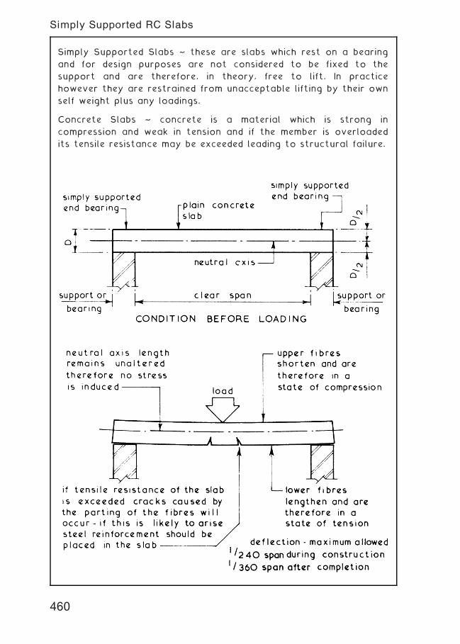
Simply Supported Slabs ~ these are slabs which rest on a bearing
and for design purposes are not considered to be fixed to the
support and are therefore, in theory, free to lift. In practice
however they are restrained from unacceptable lifting by their own
self weight plus any loadings.
Concrete Slabs ~ concrete is a material which is strong in
compression and weak in tension and if the member is overloaded
its tensile resistance may be exceeded leading to structural failure.
460
Simply Supported RC Slabs
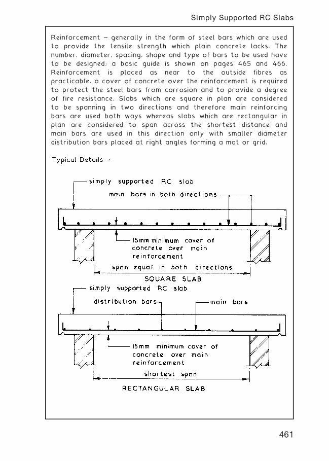
Reinforcement ~ generally in the form of steel bars which are used
to provide the tensile strength which plain concrete lacks. The
number, diameter, spacing, shape and type of bars to be used have
to be designed; a basic guide is shown on pages 465 and 466.
Reinforcement is placed as near to the outside fibres as
practicable, a cover of concrete over the reinforcement is required
to protect the steel bars from corrosion and to provide a degree
of fire resistance. Slabs which are square in plan are considered
to be spanning in two directions and therefore main reinforcing
bars are used both ways whereas slabs which are rectangular in
plan are considered to span across the shortest distance and
main bars are used in this direction only with smaller diameter
distribution bars placed at right angles forming a mat or grid.
461
Simply Supported RC Slabs
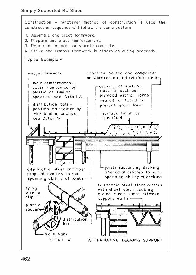
Construction ~ whatever method of construction is used the
construction sequence will follow the same pattern-
1. Assemble and erect formwork.
2. Prepare and place reinforcement.
3. Pour and compact or vibrate concrete.
4. Strike and remove formwork in stages as curing proceeds.
462
Simply Supported RC Slabs
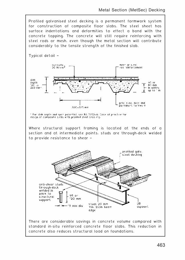
Profiled galvanised steel decking is a permanent formwork system
for construction of composite floor slabs. The steel sheet has
surface indentations and deformities to effect a bond with the
concrete topping. The concrete will still require reinforcing with
steel rods or mesh, even though the metal section will contribute
considerably to the tensile strength of the finished slab.
Typical detail †
Where structural support framing is located at the ends of a
section and at intermediate points, studs are through-deck welded
to provide resistance to shear †
There are considerable savings in concrete volume compared with
standard in-situ reinforced concrete floor slabs. This reduction in
concrete also reduces structural load on foundations.
463
Metal Section (MetSec) Decking
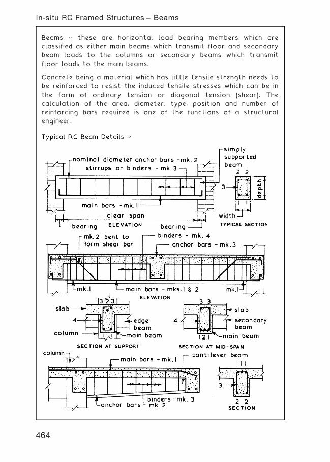
Beams ~ these are horizontal load bearing members which are
classified as either main beams which transmit floor and secondary
beam loads to the columns or secondary beams which transmit
floor loads to the main beams.
Concrete being a material which has little tensile strength needs to
be reinforced to resist the induced tensile stresses which can be in
the form of ordinary tension or diagonal tension (shear). The
calculation of the area, diameter, type, position and number of
reinforcing bars required is one of the functions of a structural
engineer.
464
In-situ RC Framed Structures -- Beams
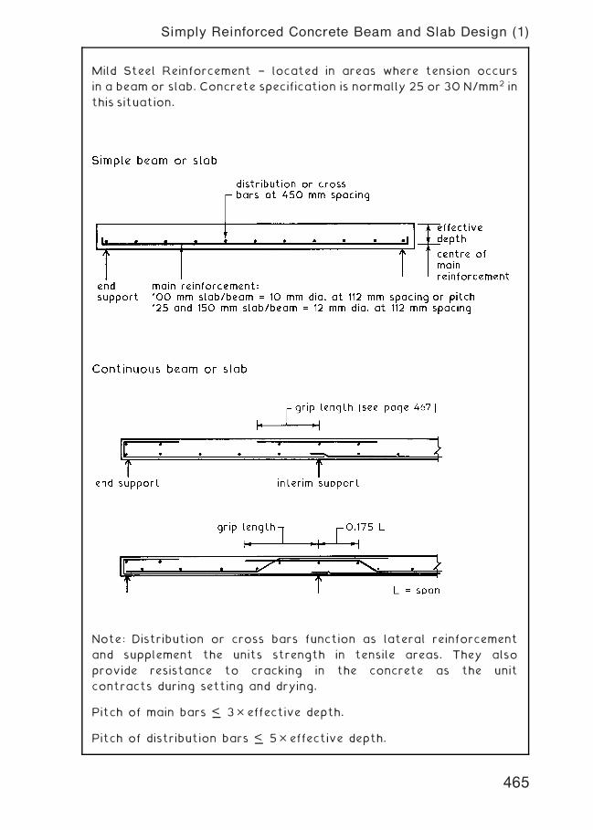
Mild Steel Reinforcement † located in areas where tension occurs
in a beam or slab. Concrete specification is normally 25 or 30 N/mm2 in
this situation.
Note: Distribution or cross bars function as lateral reinforcement
and supplement the units strength in tensile areas. They also
provide resistance to cracking in the concrete as the unit
contracts during setting and drying.
Pitch of main bars <… 3� effective depth.
Pitch of distribution bars <… 5� effective depth.
465
Simply Reinforced Concrete Beam and Slab Design (1)
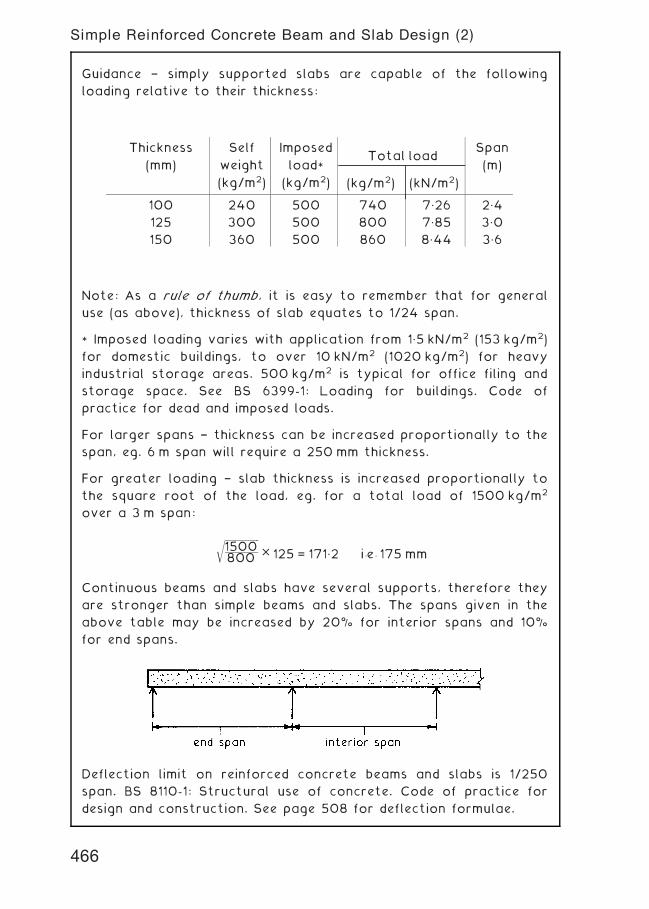
Guidance † simply supported slabs are capable of the following
loading relative to their thickness:
Note: As a rule of thumb, it is easy to remember that for general
use (as above), thickness of slab equates to 1/24 span.
* Imposed loading varies with application from 1„5 kN/m2 (153 kg/m2)
for domestic buildings, to over 10 kN/m2 (1020 kg/m2) for heavy
industrial storage areas. 500 kg/m2 is typical for office filing and
storage space. See BS 6399-1: Loading for buildings. Code of
practice for dead and imposed loads.
For larger spans † thickness can be increased proportionally to the
span, eg. 6 m span will require a 250 mm thickness.
For greater loading † slab thickness is increased proportionally to
the square root of the load, eg. for a total load of 1500 kg/m2
over a 3 m span:
ffiffiffiffiffiffiffiffiffiffiffiffiffiffiffiffiffiffi
1500800
r
� 125 = 171„2 i:e: 175 mm
Continuous beams and slabs have several supports, therefore they
are stronger than simple beams and slabs. The spans given in the
above table may be increased by 20% for interior spans and 10%
for end spans.
Deflection limit on reinforced concrete beams and slabs is 1/250
span. BS 8110-1: Structural use of concrete. Code of practice for
design and construction. See page 508 for deflection formulae.
Thickness
(mm)
Self
weight
(kg/m2)
Imposed
load*(kg/m2)
Total load
(kg/m2) (kN/m2)
Span
(m)
100 240 500 740 7„26 2„4
125 300 500 800 7„85 3„0
150 360 500 860 8„44 3„6
466
Simple Reinforced Concrete Beam and Slab Design (2)
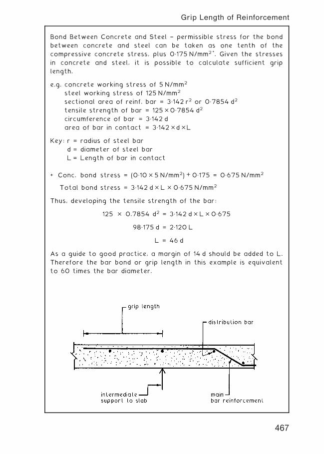
Bond Between Concrete and Steel † permissible stress for the bond
between concrete and steel can be taken as one tenth of the
compressive concrete stress, plus 0„175 N/mm2*. Given the stresses
in concrete and steel, it is possible to calculate sufficient grip
length.
e.g. concrete working stress of 5 N/mm2
steel working stress of 125 N/mm2
sectional area of reinf. bar = 3„142 r2 or 0„7854 d2
tensile strength of bar = 125�0„7854 d2
circumference of bar = 3„142 d
area of bar in contact = 3„142�d�L
Key: r = radius of steel bar
d = diameter of steel bar
L = Length of bar in contact
* Conc. bond stress = (0„10� 5 N/mm2) + 0„175 = 0„675 N/mm2
Total bond stress = 3„142 d� L � 0„675 N/mm2
Thus, developing the tensile strength of the bar:
125 � 0.7854 d2 = 3„142 d� L� 0„675
98„175 d = 2„120 L
L = 46 d
As a guide to good practice, a margin of 14 d should be added to L.
Therefore the bar bond or grip length in this example is equivalent
to 60 times the bar diameter.
467
Grip Length of Reinforcement
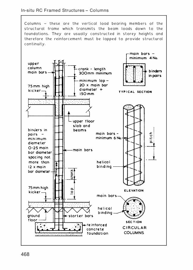
Columns ~ these are the vertical load bearing members of the
structural frame which transmits the beam loads down to the
foundations. They are usually constructed in storey heights and
therefore the reinforcement must be lapped to provide structural
continuity.
468
In-situ RC Framed Structures -- Columns
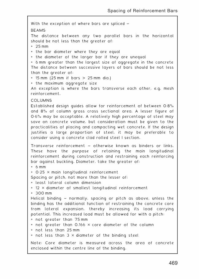
With the exception of where bars are spliced ~
BEAMS
The distance between any two parallel bars in the horizontal
should be not less than the greater of:
* 25 mm
* the bar diameter where they are equal
* the diameter of the larger bar if they are unequal
* 6 mm greater than the largest size of aggregate in the concrete
The distance between successive layers of bars should be not less
than the greater of:
* 15 mm (25 mm if bars > 25 mm dia.)
* the maximum aggregate size
An exception is where the bars transverse each other, e.g. mesh
reinforcement.
COLUMNS
Established design guides allow for reinforcement of between 0„8%
and 8% of column gross cross sectional area. A lesser figure of
0„6% may be acceptable. A relatively high percentage of steel may
save on concrete volume, but consideration must be given to the
practicalities of placing and compacting wet concrete. If the design
justifies a large proportion of steel, it may be preferable to
consider using a concrete clad rolled steel I section.
Transverse reinforcement ~ otherwise known as binders or links.
These have the purpose of retaining the main longitudinal
reinforcement during construction and restraining each reinforcing
bar against buckling. Diameter, take the greater of:
* 6 mm
* 0„25 � main longitudinal reinforcement
Spacing or pitch, not more than the lesser of:
* least lateral column dimension
* 12 � diameter of smallest longitudinal reinforcement
* 300mm
Helical binding ~ normally, spacing or pitch as above, unless the
binding has the additional function of restraining the concrete core
from lateral expansion, thereby increasing its load carrying
potential. This increased load must be allowed for with a pitch:
* not greater than 75 mm
* not greater than 0.166 � core diameter of the column
* not less than 25 mm
* not less than 3 � diameter of the binding steel
Note: Core diameter is measured across the area of concrete
enclosed within the centre line of the binding.
469
Spacing of Reinforcement Bars
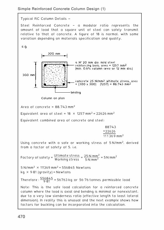
Typical RC Column Details ~
Steel Reinforced Concrete † a modular ratio represents the
amount of load that a square unit of steel can safely transmit
relative to that of concrete. A figure of 18 is normal, with some
variation depending on materials specification and quality.
Area of concrete = 88,743 mm2
Equivalent area of steel = 18 � 1257 mm2 = 22626 mm2
Equivalent combined area of concrete and steel:
88743
+22626
11 1 369 mm2
Using concrete with a safe or working stress of 5 N/mm2, derived
from a factor of safety of 5, i.e.
Factory of safety =Ultimate stressWorking stress
= 25N=mm2
5N=mm2 = 5N=mm2
5 N/mm2 � 111369 mm2 = 556845 Newtons
kg � 9„81 (gravity) = Newtons
Therefore : 5568459„81 = 56763 kg or 56„76 tonnes permissible load
Note: This is the safe load calculation for a reinforced concrete
column where the load is axial and bending is minimal or nonexistant,
due to a very low slenderness ratio (effective length to least lateral
dimension). In reality this is unusual and the next example shows how
factors for buckling can be incorporated into the calculation.
470
Simple Reinforced Concrete Column Design (1)
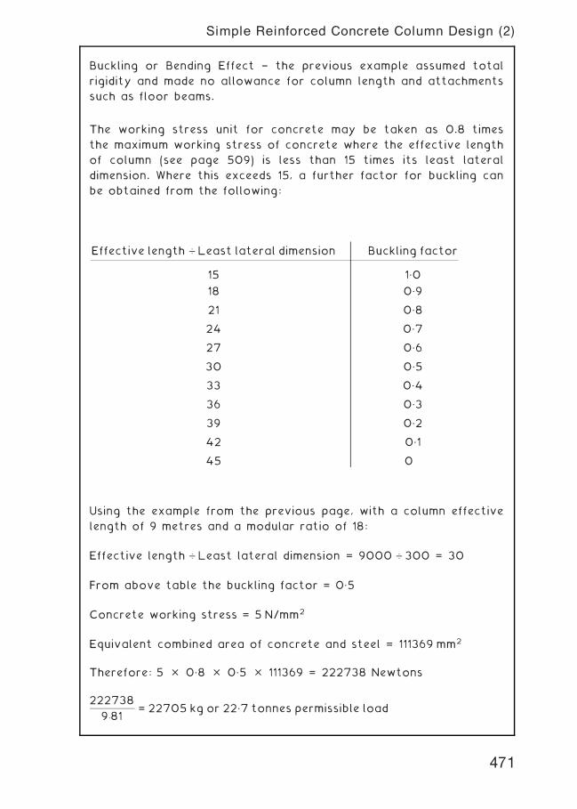
Buckling or Bending Effect † the previous example assumed total
rigidity and made no allowance for column length and attachments
such as floor beams.
The working stress unit for concrete may be taken as 0.8 times
the maximum working stress of concrete where the effective length
of column (see page 509) is less than 15 times its least lateral
dimension. Where this exceeds 15, a further factor for buckling can
be obtained from the following:
Using the example from the previous page, with a column effective
length of 9 metres and a modular ratio of 18:
Effective length … Least lateral dimension = 9000 … 300 = 30
From above table the buckling factor = 0„5
Concrete working stress = 5 N/mm2
Equivalent combined area of concrete and steel = 111369 mm2
Therefore: 5 � 0„8 � 0„5 � 111369 = 222738 Newtons
222738
9:81= 22705 kg or 22„7 tonnes permissible load
Effective length … Least lateral dimension Buckling factor
15 1„0
18 0„9
21 0„8
24 0„7
27 0„6
30 0„5
33 0„4
36 0„3
39 0„2
42 0„1
45 0
471
Simple Reinforced Concrete Column Design (2)
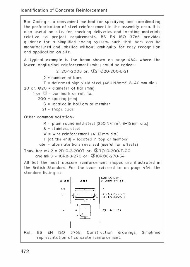
Bar Coding ~ a convenient method for specifying and coordinating
the prefabrication of steel reinforcement in the assembly area. It is
also useful on site, for checking deliveries and locating materials
relative to project requirements. BS EN ISO 3766 provides
guidance for a simplified coding system, such that bars can be
manufactured and labelled without ambiguity for easy recognition
and application on site.
A typical example is the beam shown on page 464, where the
lower longitudinal reinforcement (mk„1) could be coded:~
2T20-1-200B or, *1 2TO= 20-200-B-21
2 = number of bars
T = deformed high yield steel (460 N/mm2, 8†40 mm dia.)
20 or, O= 20 = diameter of bar (mm)
1 or *1 = bar mark or ref. no.
200 = spacing (mm)
B = located in bottom of member
21 = shape code
Other common notation:-
R = plain round mild steel (250 N/mm2, 8†16 mm dia.)
S = stainless steel
W = wire reinforcement (4†12 mm dia.)
T (at the end) = located in top of member
abr = alternate bars reversed (useful for offsets)
Thus, bar mk.2 = 2R10-2-200T or, *2 RO= 10-200-T-00
and mk.3 = 10R8-3-270 or, *3 10RO= 8-270-54
All but the most obscure reinforcement shapes are illustrated in
the British Standard. For the beam referred to on page 464, the
standard listing is:-
Ref. BS EN ISO 3766: Construction drawings. Simplified
representation of concrete reinforcement.
472
Identification of Concrete Reinforcement
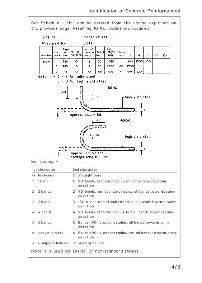
Bar Schedule ~ this can be derived from the coding explained on
the previous page. Assuming 10 No. beams are required:-
Bar coding ~
Note: 9 is used for special or non-standard shapes
1st character 2nd character
0 No bends 0 Straight bars
1 1 bend 1 90� bends, standard radius, all bends towards same
direction
2 2 bends 2 90� bends, non-standard radius, all bends towards same
direction
3 3 bends 3 180� bends, non-standard radius, all bends towards same
direction
4 4 bends 4 90� bends, standard radius, not all bends towards same
direction
5 5 bends 5 Bends <90�, standard radius, all bends towards same
direction
6 Arcs of circles 6 Bends <90�, standard radius, not all bends towards same
direction
7 Complete helices 7 Arcs or helices
473
Identification of Concrete Reinforcement
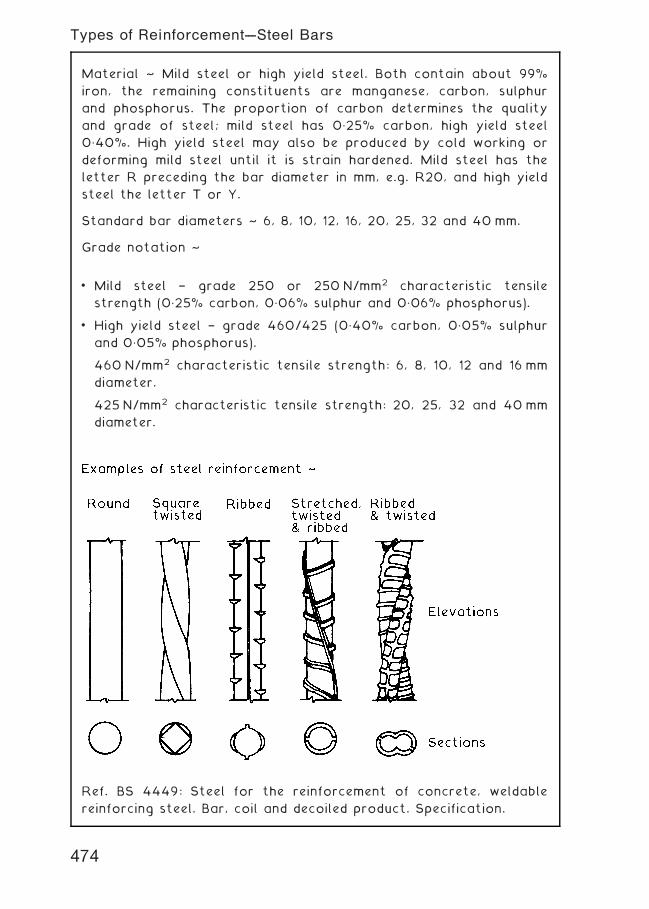
Material ~ Mild steel or high yield steel. Both contain about 99%
iron, the remaining constituents are manganese, carbon, sulphur
and phosphorus. The proportion of carbon determines the quality
and grade of steel; mild steel has 0„25% carbon, high yield steel
0„40%. High yield steel may also be produced by cold working or
deforming mild steel until it is strain hardened. Mild steel has the
letter R preceding the bar diameter in mm, e.g. R20, and high yield
steel the letter T or Y.
Standard bar diameters ~ 6, 8, 10, 12, 16, 20, 25, 32 and 40 mm.
Grade notation ~
• Mild steel † grade 250 or 250 N/mm2 characteristic tensile
strength (0„25% carbon, 0„06% sulphur and 0„06% phosphorus).
• High yield steel † grade 460/425 (0„40% carbon, 0„05% sulphur
and 0„05% phosphorus).
460 N/mm2 characteristic tensile strength: 6, 8, 10, 12 and 16 mm
diameter.
425 N/mm2 characteristic tensile strength: 20, 25, 32 and 40mm
diameter.
Ref. BS 4449: Steel for the reinforcement of concrete, weldable
reinforcing steel. Bar, coil and decoiled product. Specification.
474
Types of Reinforcement---Steel Bars
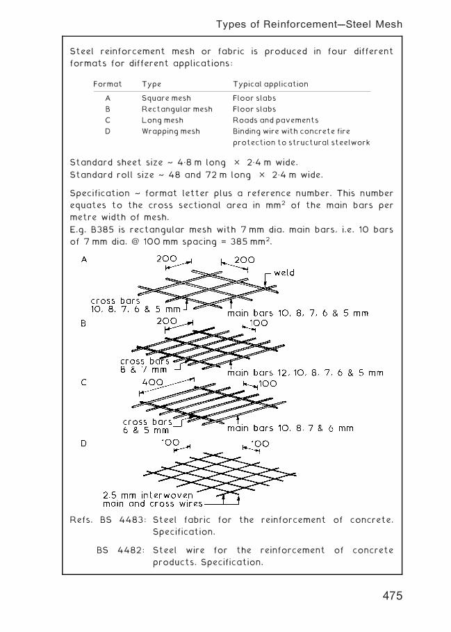
Steel reinforcement mesh or fabric is produced in four different
formats for different applications:
Standard sheet size ~ 4„8 m long � 2„4 m wide.
Standard roll size ~ 48 and 72 m long � 2„4 m wide.
Specification ~ format letter plus a reference number. This number
equates to the cross sectional area in mm2 of the main bars per
metre width of mesh.
E.g. B385 is rectangular mesh with 7 mm dia. main bars, i.e. 10 bars
of 7 mm dia. @ 100 mm spacing = 385 mm2.
Refs. BS 4483: Steel fabric for the reinforcement of concrete.
Specification.
BS 4482: Steel wire for the reinforcement of concrete
products. Specification.
Format Type Typical application
A Square mesh Floor slabs
B Rectangular mesh Floor slabs
C Long mesh Roads and pavements
D Wrapping mesh Binding wire with concrete fire
protection to structural steelwork
475
Types of Reinforcement---Steel Mesh
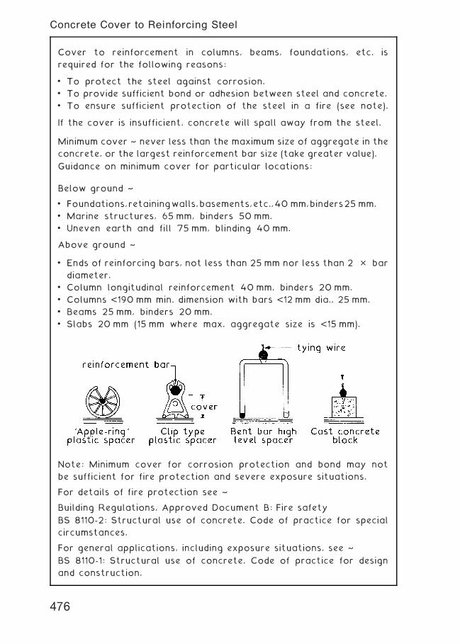
Cover to reinforcement in columns, beams, foundations, etc. is
required for the following reasons:
• To protect the steel against corrosion.
• To provide sufficient bond or adhesion between steel and concrete.
• To ensure sufficient protection of the steel in a fire (see note).
If the cover is insufficient, concrete will spall away from the steel.
Minimum cover ~ never less than the maximum size of aggregate in the
concrete, or the largest reinforcement bar size (take greater value).
Guidance on minimum cover for particular locations:
Below ground ~
• Foundations,retainingwalls,basements,etc.,40 mm,binders25 mm.
• Marine structures, 65 mm, binders 50 mm.
• Uneven earth and fill 75 mm, blinding 40 mm.
Above ground ~
• Ends of reinforcing bars, not less than 25 mm nor less than 2 � bar
diameter.
• Column longitudinal reinforcement 40 mm, binders 20 mm.
• Columns <190 mm min. dimension with bars <12 mm dia., 25 mm.
• Beams 25 mm, binders 20 mm.
• Slabs 20 mm (15 mm where max. aggregate size is <15 mm).
Note: Minimum cover for corrosion protection and bond may not
be sufficient for fire protection and severe exposure situations.
For details of fire protection see ~
Building Regulations, Approved Document B: Fire safety
BS 8110-2: Structural use of concrete. Code of practice for special
circumstances.
For general applications, including exposure situations, see ~
BS 8110-1: Structural use of concrete. Code of practice for design
and construction.
476
Concrete Cover to Reinforcing Steel
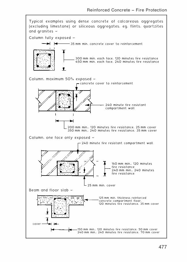
Typical examples using dense concrete of calcareous aggregates
(excluding limestone) or siliceous aggregates, eg. flints, quartzites
and granites ~
Column fully exposed ~
35 mm min. concrete cover to reinforcement
300 mm min. each face, 120 minutes fire resistance450 mm min. each face, 240 minutes fire resistance
Column, maximum 50% exposed ~
200 mm min., 120 minutes fire resistance, 25 mm cover350 mm min., 240 minutes fire resistance, 35 mm cover
concrete cover to reinforcement
240 minute fire resistantcompartment wall
Column, one face only exposed ~
160 mm min., 120 minutesfire resistance240 mm min., 240 minutesfire resistance
25 mm min. cover
240 minute fire resistant compartment wall
Beam and floor slab ~
125 mm min. thickness reinforcedconcrete compartment floor,120 minutes fire resistance, 35 mm cover
cover
150 mm min., 120 minutes fire resistance, 50 mm cover240 mm min., 240 minutes fire resistance, 70 mm cover
477
Reinforced Concrete -- Fire Protection
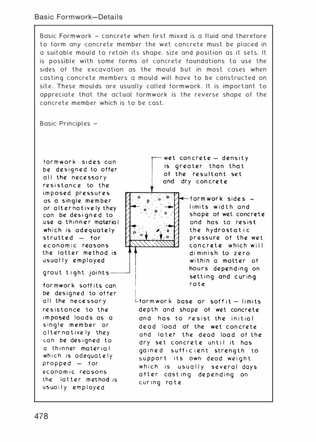
Basic Formwork ~ concrete when first mixed is a fluid and therefore
to form any concrete member the wet concrete must be placed in
a suitable mould to retain its shape, size and position as it sets. It
is possible with some forms of concrete foundations to use the
sides of the excavation as the mould but in most cases when
casting concrete members a mould will have to be constructed on
site. These moulds are usually called formwork. It is important to
appreciate that the actual formwork is the reverse shape of the
concrete member which is to be cast.
Basic Principles ~
478
Basic Formwork---Details
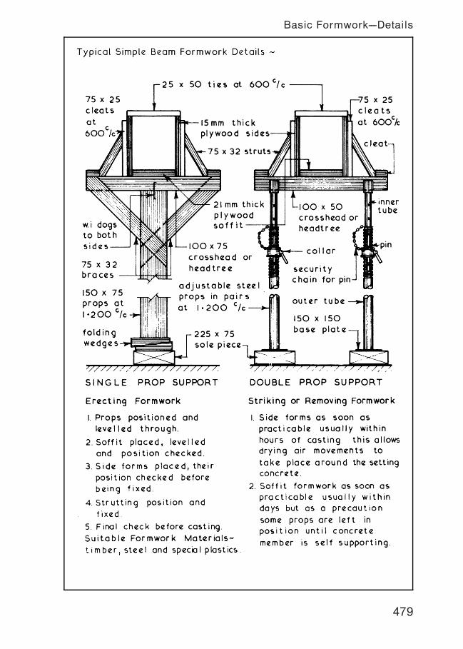
479
Basic Formwork---Details
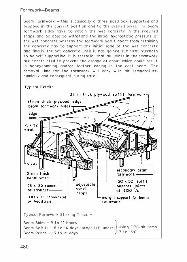
Beam Formwork ~ this is basically a three sided box supported and
propped in the correct position and to the desired level. The beam
formwork sides have to retain the wet concrete in the required
shape and be able to withstand the initial hydrostatic pressure of
the wet concrete whereas the formwork soffit apart from retaining
the concrete has to support the initial load of the wet concrete
and finally the set concrete until it has gained sufficient strength
to be self supporting. It is essential that all joints in the formwork
are constructed to prevent the escape of grout which could result
in honeycombing and/or feather edging in the cast beam. The
removal time for the formwork will vary with air temperature,
humidity and consequent curing rate.
Typical Formwork Striking Times ~
Beam Sides † 9 to 12 hours
Beam Soffits † 8 to 14 days (props left under)
Beam Props † 15 to 21 days
)
Using OPC-air temp
7 to 16�C
480
Formwork---Beams

Column Formwork ~ this consists of a vertical mould of the desired
shape and size which has to retain the wet concrete and resist the
initial hydrostatic pressure caused by the wet concrete. To keep
the thickness of the formwork material to a minimum horizontal
clamps or yokes are used at equal centres for batch filling and at
varying centres for complete filling in one pour. The head of the
column formwork can be used to support the incoming beam
formwork which gives good top lateral restraint but results in
complex formwork. Alternatively the column can be cast to the
underside of the beams and at a later stage a collar of formwork
can be clamped around the cast column to complete casting and
support the incoming beam formwork. Column forms are located at
the bottom around a 75 to 100 mm high concrete plinth or kicker
which has the dual function of location and preventing grout loss
from the bottom of the column formwork.
481
Formwork---Columns
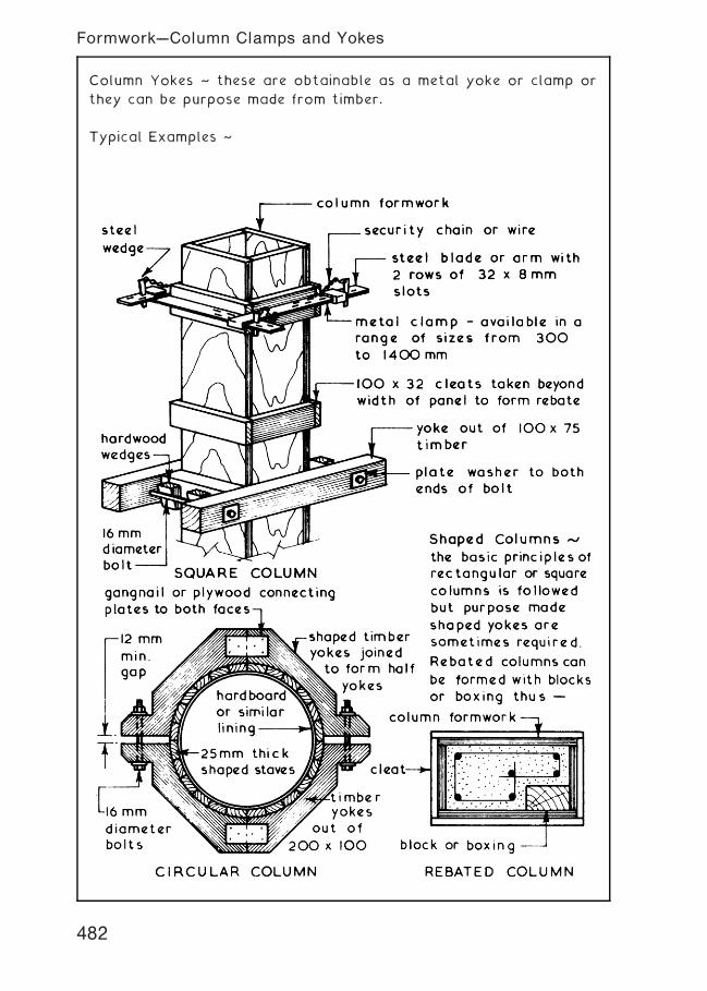
Column Yokes ~ these are obtainable as a metal yoke or clamp or
they can be purpose made from timber.
Typical Examples ~
482
Formwork---Column Clamps and Yokes
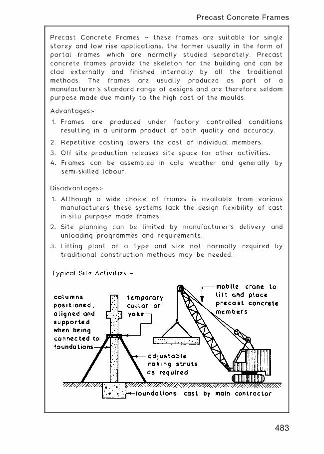
Precast Concrete Frames ~ these frames are suitable for single
storey and low rise applications, the former usually in the form of
portal frames which are normally studied separately. Precast
concrete frames provide the skeleton for the building and can be
clad externally and finished internally by all the traditional
methods. The frames are usually produced as part of a
manufacturer's standard range of designs and are therefore seldom
purpose made due mainly to the high cost of the moulds.
Advantages:-
1. Frames are produced under factory controlled conditions
resulting in a uniform product of both quality and accuracy.
2. Repetitive casting lowers the cost of individual members.
3. Off site production releases site space for other activities.
4. Frames can be assembled in cold weather and generally by
semi-skilled labour.
Disadvantages:-
1. Although a wide choice of frames is available from various
manufacturers these systems lack the design flexibility of cast
in-situ purpose made frames.
2. Site planning can be limited by manufacturer's delivery and
unloading programmes and requirements.
3. Lifting plant of a type and size not normally required by
traditional construction methods may be needed.
483
Precast Concrete Frames
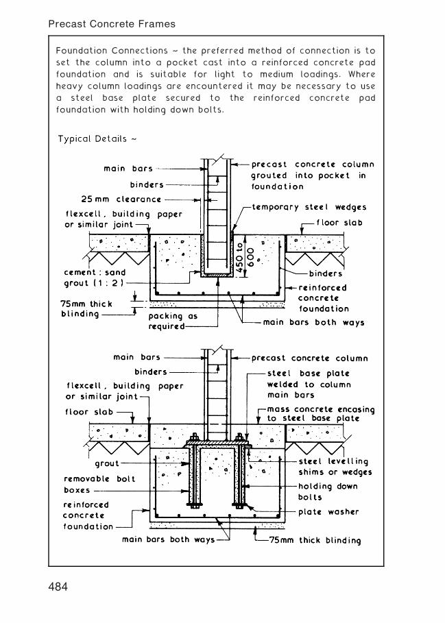
Foundation Connections ~ the preferred method of connection is to
set the column into a pocket cast into a reinforced concrete pad
foundation and is suitable for light to medium loadings. Where
heavy column loadings are encountered it may be necessary to use
a steel base plate secured to the reinforced concrete pad
foundation with holding down bolts.
484
Precast Concrete Frames
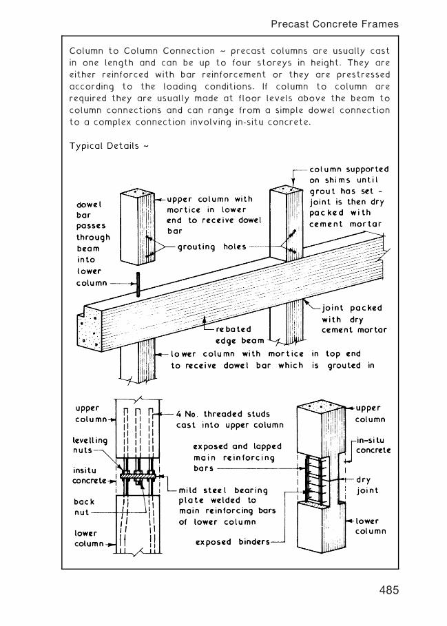
Column to Column Connection ~ precast columns are usually cast
in one length and can be up to four storeys in height. They are
either reinforced with bar reinforcement or they are prestressed
according to the loading conditions. If column to column are
required they are usually made at floor levels above the beam to
column connections and can range from a simple dowel connection
to a complex connection involving in-situ concrete.
485
Precast Concrete Frames
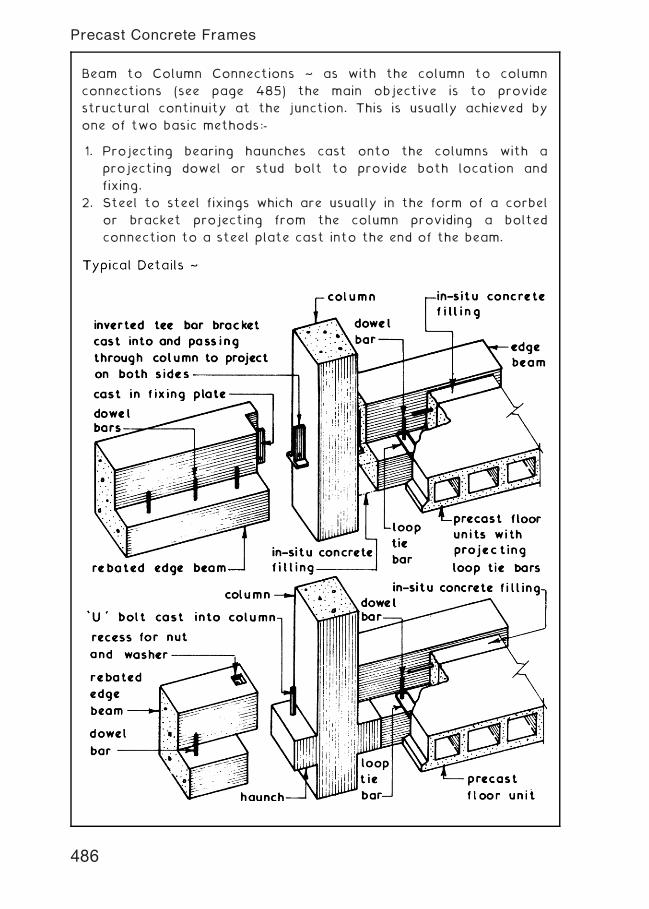
Beam to Column Connections ~ as with the column to column
connections (see page 485) the main objective is to provide
structural continuity at the junction. This is usually achieved by
one of two basic methods:-
1. Projecting bearing haunches cast onto the columns with a
projecting dowel or stud bolt to provide both location and
fixing.
2. Steel to steel fixings which are usually in the form of a corbel
or bracket projecting from the column providing a bolted
connection to a steel plate cast into the end of the beam.
486
Precast Concrete Frames
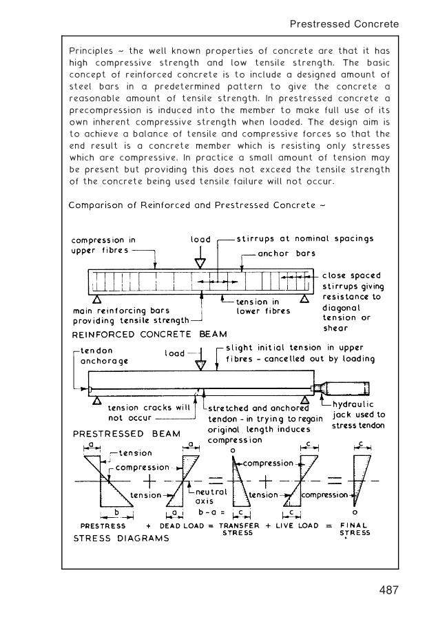
Principles ~ the well known properties of concrete are that it has
high compressive strength and low tensile strength. The basic
concept of reinforced concrete is to include a designed amount of
steel bars in a predetermined pattern to give the concrete a
reasonable amount of tensile strength. In prestressed concrete a
precompression is induced into the member to make full use of its
own inherent compressive strength when loaded. The design aim is
to achieve a balance of tensile and compressive forces so that the
end result is a concrete member which is resisting only stresses
which are compressive. In practice a small amount of tension may
be present but providing this does not exceed the tensile strength
of the concrete being used tensile failure will not occur.
487
Prestressed Concrete
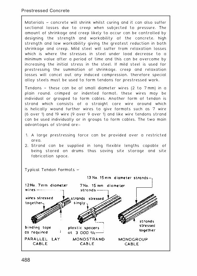
Materials ~ concrete will shrink whilst curing and it can also suffer
sectional losses due to creep when subjected to pressure. The
amount of shrinkage and creep likely to occur can be controlled by
designing the strength and workability of the concrete, high
strength and low workability giving the greatest reduction in both
shrinkage and creep. Mild steel will suffer from relaxation losses
which is where the stresses in steel under load decrease to a
minimum value after a period of time and this can be overcome by
increasing the initial stress in the steel. If mild steel is used for
prestressing the summation of shrinkage, creep and relaxation
losses will cancel out any induced compression, therefore special
alloy steels must be used to form tendons for prestressed work.
Tendons † these can be of small diameter wires (2 to 7 mm) in a
plain round, crimped or indented format, these wires may be
individual or grouped to form cables. Another form of tendon is
strand which consists of a straight core wire around which
is helically wound further wires to give formats such as 7 wire
(6 over 1) and 19 wire (9 over 9 over 1) and like wire tendons strand
can be used individually or in groups to form cables. The two main
advantages of strand are:-
1. A large prestressing force can be provided over a restricted
area.
2. Strand can be supplied in long flexible lengths capable of
being stored on drums thus saving site storage and site
fabrication space.
488
Prestressed Concrete
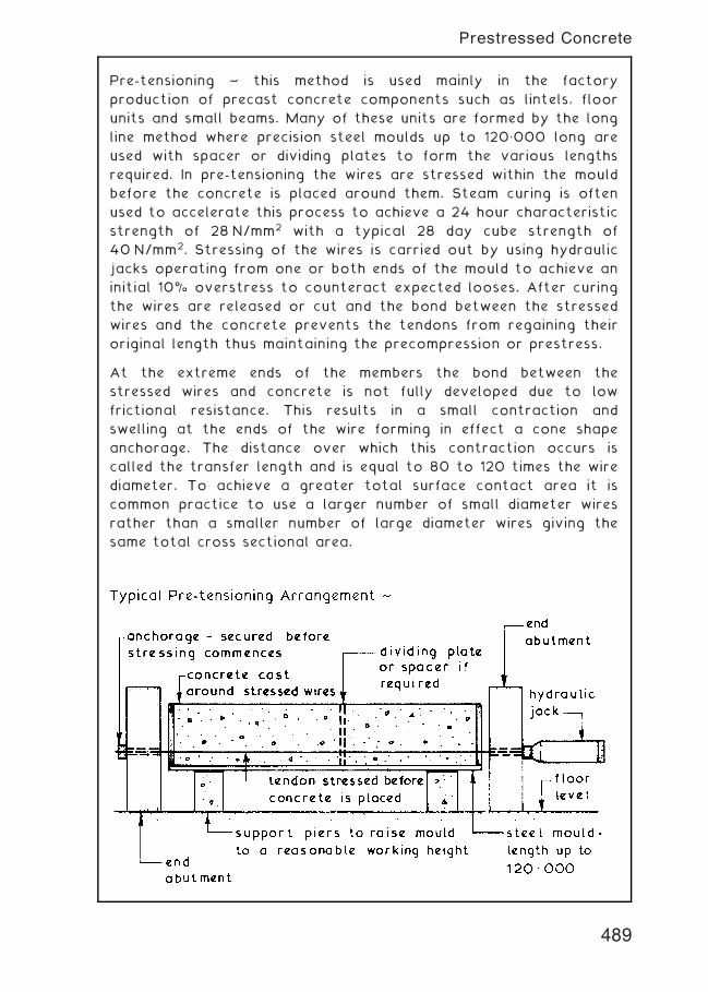
Pre-tensioning ~ this method is used mainly in the factory
production of precast concrete components such as lintels, floor
units and small beams. Many of these units are formed by the long
line method where precision steel moulds up to 120„000 long are
used with spacer or dividing plates to form the various lengths
required. In pre-tensioning the wires are stressed within the mould
before the concrete is placed around them. Steam curing is often
used to accelerate this process to achieve a 24 hour characteristic
strength of 28 N/mm2 with a typical 28 day cube strength of
40 N/mm2. Stressing of the wires is carried out by using hydraulic
jacks operating from one or both ends of the mould to achieve an
initial 10% overstress to counteract expected looses. After curing
the wires are released or cut and the bond between the stressed
wires and the concrete prevents the tendons from regaining their
original length thus maintaining the precompression or prestress.
At the extreme ends of the members the bond between the
stressed wires and concrete is not fully developed due to low
frictional resistance. This results in a small contraction and
swelling at the ends of the wire forming in effect a cone shape
anchorage. The distance over which this contraction occurs is
called the transfer length and is equal to 80 to 120 times the wire
diameter. To achieve a greater total surface contact area it is
common practice to use a larger number of small diameter wires
rather than a smaller number of large diameter wires giving the
same total cross sectional area.
489
Prestressed Concrete
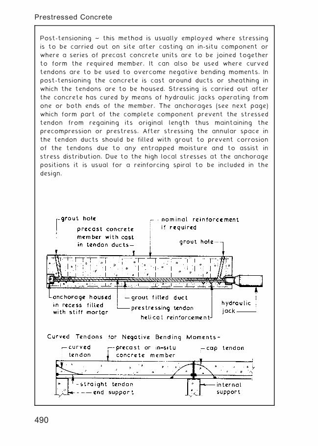
Post-tensioning ~ this method is usually employed where stressing
is to be carried out on site after casting an in-situ component or
where a series of precast concrete units are to be joined together
to form the required member. It can also be used where curved
tendons are to be used to overcome negative bending moments. In
post-tensioning the concrete is cast around ducts or sheathing in
which the tendons are to be housed. Stressing is carried out after
the concrete has cured by means of hydraulic jacks operating from
one or both ends of the member. The anchorages (see next page)
which form part of the complete component prevent the stressed
tendon from regaining its original length thus maintaining the
precompression or prestress. After stressing the annular space in
the tendon ducts should be filled with grout to prevent corrosion
of the tendons due to any entrapped moisture and to assist in
stress distribution. Due to the high local stresses at the anchorage
positions it is usual for a reinforcing spiral to be included in the
design.
490
Prestressed Concrete
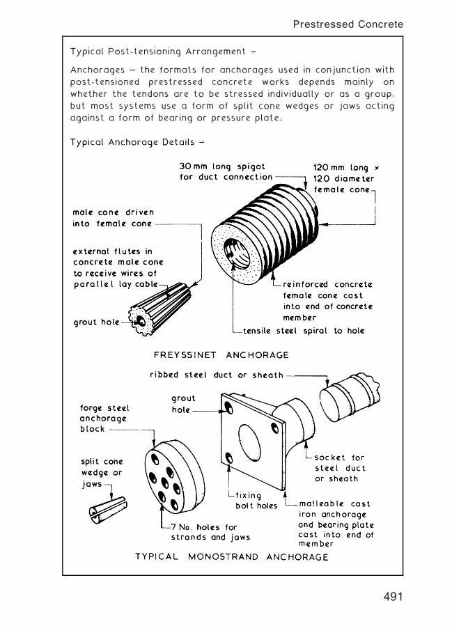
Typical Post-tensioning Arrangement ~
Anchorages ~ the formats for anchorages used in conjunction with
post-tensioned prestressed concrete works depends mainly on
whether the tendons are to be stressed individually or as a group,
but most systems use a form of split cone wedges or jaws acting
against a form of bearing or pressure plate.
491
Prestressed Concrete
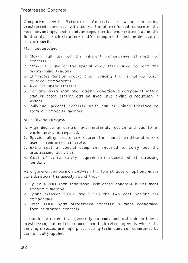
Comparison with Reinforced Concrete ~ when comparing
prestressed concrete with conventional reinforced concrete the
main advantages and disadvantages can be enumerated but in the
final analysis each structure and/or component must be decided on
its own merit.
Main advantages:-
1. Makes full use of the inherent compressive strength of
concrete.
2. Makes full use of the special alloy steels used to form the
prestressing tendons.
3. Eliminates tension cracks thus reducing the risk of corrosion
of steel components.
4. Reduces shear stresses.
5. For any given span and loading condition a component with a
smaller cross section can be used thus giving a reduction in
weight.
6. Individual precast concrete units can be joined together to
form a composite member.
Main Disadvantages:-
1. High degree of control over materials, design and quality of
workmanship is required.
2. Special alloy steels are dearer than most traditional steels
used in reinforced concrete.
3. Extra cost of special equipment required to carry out the
prestressing activities.
4. Cost of extra safety requirements needed whilst stressing
tendons.
As a general comparison between the two structural options under
consideration it is usually found that:-
1. Up to 6„000 span traditional reinforced concrete is the most
economic method.
2. Spans between 6„000 and 9„000 the two cost options are
comparable.
3. Over 9„000 span prestressed concrete is more economical
than reinforced concrete.
It should be noted that generally columns and walls do not need
prestressing but in tall columns and high retaining walls where the
bending stresses are high, prestressing techniques can sometimes be
economically applied.
492
Prestressed Concrete
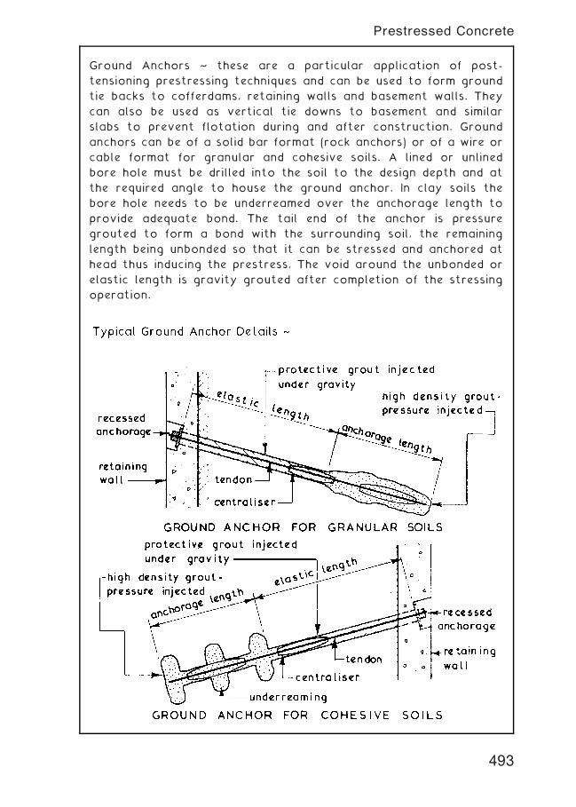
Ground Anchors ~ these are a particular application of post-
tensioning prestressing techniques and can be used to form ground
tie backs to cofferdams, retaining walls and basement walls. They
can also be used as vertical tie downs to basement and similar
slabs to prevent flotation during and after construction. Ground
anchors can be of a solid bar format (rock anchors) or of a wire or
cable format for granular and cohesive soils. A lined or unlined
bore hole must be drilled into the soil to the design depth and at
the required angle to house the ground anchor. In clay soils the
bore hole needs to be underreamed over the anchorage length to
provide adequate bond. The tail end of the anchor is pressure
grouted to form a bond with the surrounding soil, the remaining
length being unbonded so that it can be stressed and anchored at
head thus inducing the prestress. The void around the unbonded or
elastic length is gravity grouted after completion of the stressing
operation.
493
Prestressed Concrete
Cold rolled steel sections are a lightweight alternative to the
relatively heavy, hot rolled steel sections that have been
traditionally used in sub-framing situations, e.g. purlins, joists and
sheeting rails. Cold rolled sections are generally only a few
millimetres in wall thickness, saving on material and handling costs
and building dead load. They are also produced in a wide variety of
section profiles, some of which are shown below.
Dimensions vary considerably and many non-standard profiles are
made for particular situations. A range of standard sections are
produced to:
BS EN 10162: Cold rolled steel sections. Technical delivery
conditions. Dimensional and cross sectional tolerances.
494
Structural Steelwork---Standard Cold Rolled Sections
Structural Steelwork ~ the standard sections available for use in
structural steelwork are given in BS 4-1 and BS ENs 10056 and
10210. These standards give a wide range of sizes and weights to
enable the designer to formulate an economic design.
Typical Standard Steelwork Sections ~
NB. Sizes given are serial or nominal, for actual sizes see relevant BS.
width
constant d
im.
for
each s
erial
size
constant
dim
ensio
n for
each s
erial
size
width
web web
92ƒ 52′or 90ƒ 90ƒ
root radius root radius
flangeflange
127 x 76 x 13 kg/m to914 x 419 x 388 kg/m
UNIVERSAL COLUMNS
depth
depth
widthwidth breadth
web web
95ƒ 95ƒ
rootradius
JOISTS CHANNELS HOLLOW SECTIONS
rootradius
flange
flangetoeradius
toe radius
depth
depth
depth
wall
90ƒ 90ƒ
rootradius
EQUAL ANGLES UNEQUAL ANGLES HOLLOW SECTIONS
rootradius
A B
A
A
flange flange
toeradius
toeradius
diameter
wall
UNIVERSAL BEAMS
152 x 152 x 23 kg/m to356 x 406 x 634 kg/m
25 x 25 x 1.2 kg/m to200 x 200 x 71.1 kg/m
40 x 25 x 1.91 kg/m to200 x 150 x 47.1 kg/m
21.3 dia. x 1.43 kg/m to508 dia. x 194 kg/m
76 x 76 x 13 kg/m to254 x 203 x 82 kg/m
100 x 50 x 10 kg/m to430 x 100 x 64 kg/m
50 x 30 x 2.89 kg/m to500 x 300 x 191 kg/m
495
Structural Steelwork---Standard Hot Rolled Sections
Compound Sections † these are produced by welding together
standard sections. Various profiles are possible, which can be
designed specifically for extreme situations such as very high loads
and long spans, where standard sections alone would be
insufficient. Some popular combinations of standard sections
include:
496
Structural Steelwork---Compound Sections
Open Web Beams † these are particularly suited to long spans with
light to moderate loading. The relative increase in depth will help
resist deflection and voids in the web will reduce structural dead
load.
Perforated Beam † a standard beam section with circular voids cut
about the neutral axis.
Castellated Beam † a standard beam section web is profile cut into
two by oxy-acetylene torch. The projections on each section are
welded together to create a new beam 50% deeper than the
original.
Litzka Beam † a standard beam cut as the castellated beam, but
with overall depth increased further by using spacer plates welded
to the projections. Minimal increase in weight.
Note: Voids at the end of open web beams should be filled with a
welded steel plate, as this is the area of maximum shear stress in a
beam.
497
Structural Steelwork---Open Web Beams
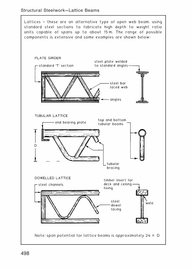
Lattices † these are an alternative type of open web beam, using
standard steel sections to fabricate high depth to weight ratio
units capable of spans up to about 15 m. The range of possible
components is extensive and some examples are shown below:
Note: span potential for lattice beams is approximately 24 � D
498
Structural Steelwork---Lattice Beams
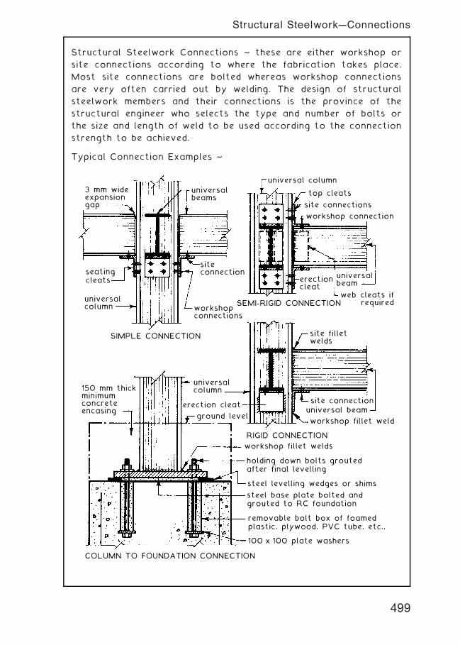
Structural Steelwork Connections ~ these are either workshop or
site connections according to where the fabrication takes place.
Most site connections are bolted whereas workshop connections
are very often carried out by welding. The design of structural
steelwork members and their connections is the province of the
structural engineer who selects the type and number of bolts or
the size and length of weld to be used according to the connection
strength to be achieved.
Typical Connection Examples ~
3 mm wideexpansiongap
universalbeams
universalbeam
erectioncleat
erection cleat
ground level
web cleats if required
site filletwelds
seatingcleats
top cleats
siteconnection
site connection
site connections
workshopconnections
workshop connection
SIMPLE CONNECTION
SEMI-RIGID CONNECTIONuniversalcolumn
universal beam
workshop fillet weld
workshop fillet welds
holding down bolts groutedafter final levelling
steel levelling wedges or shims
steel base plate bolted andgrouted to RC foundation
removable bolt box of foamedplastic, plywood, PVC tube, etc.,
100 x 100 plate washers
COLUMN TO FOUNDATION CONNECTION
RIGID CONNECTION
150 mm thickminimumconcreteencasing
universal column
universalcolumn
499
Structural Steelwork---Connections
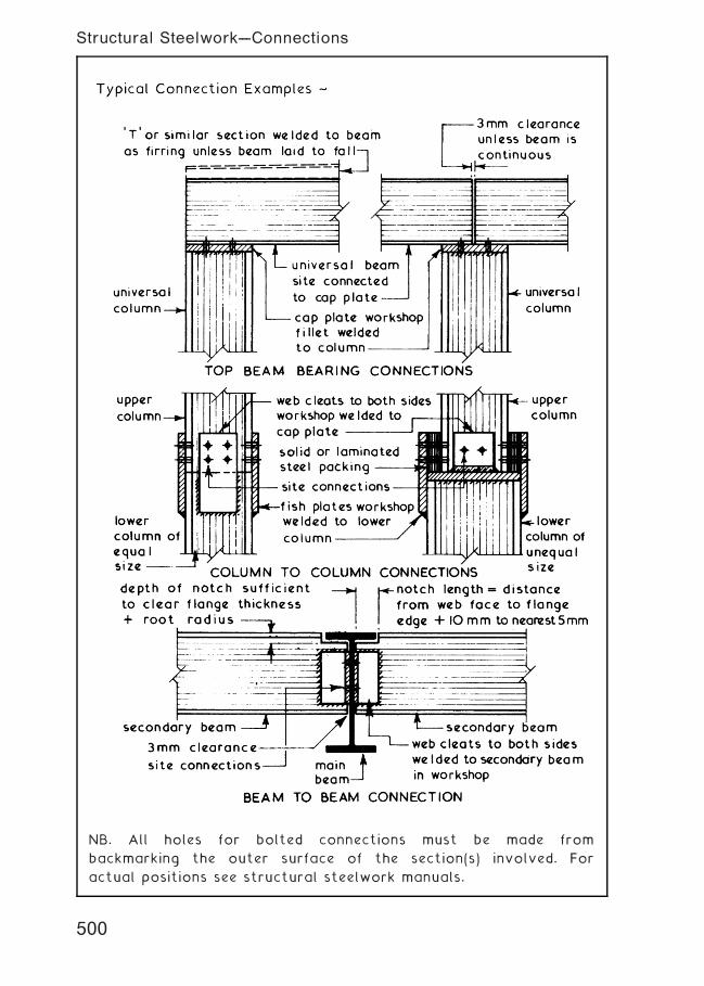
NB. All holes for bolted connections must be made from
backmarking the outer surface of the section(s) involved. For
actual positions see structural steelwork manuals.
500
Structural Steelwork---Connections
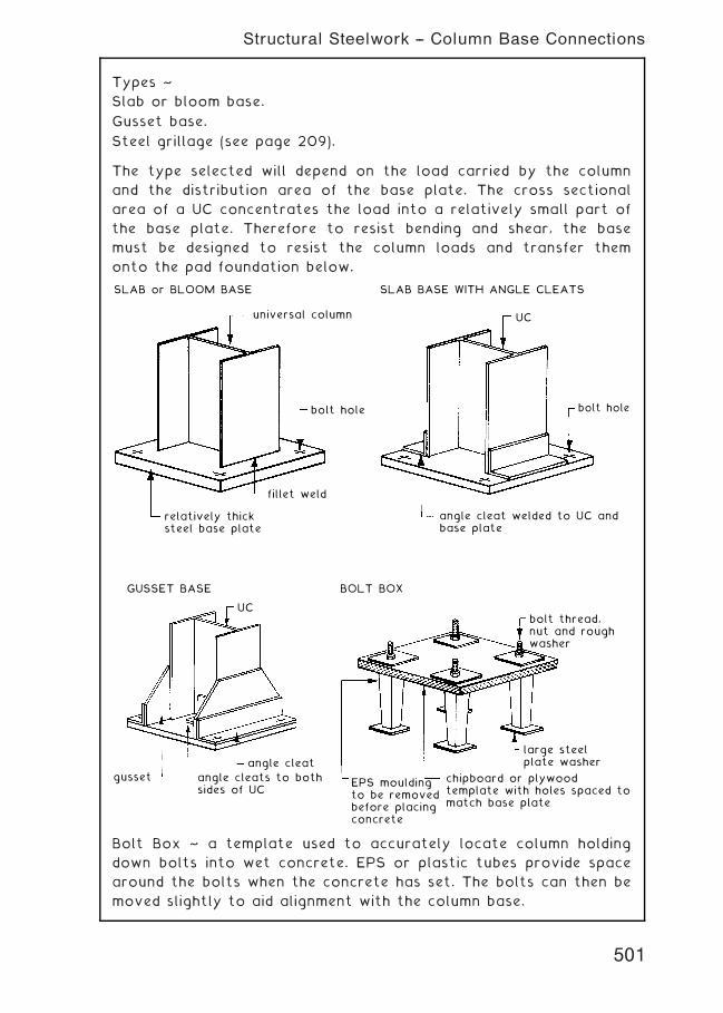
Types ~
Slab or bloom base.
Gusset base.
Steel grillage (see page 209).
The type selected will depend on the load carried by the column
and the distribution area of the base plate. The cross sectional
area of a UC concentrates the load into a relatively small part of
the base plate. Therefore to resist bending and shear, the base
must be designed to resist the column loads and transfer them
onto the pad foundation below.
SLAB or BLOOM BASE
universal column
bolt hole
fillet weld
relatively thicksteel base plate
SLAB BASE WITH ANGLE CLEATS
UC
bolt hole
angle cleat welded to UC andbase plate
GUSSET BASE
UC
angle cleat
angle cleats to bothsides of UC
gusset
BOLT BOX
EPS mouldingto be removedbefore placingconcrete
chipboard or plywoodtemplate with holes spaced tomatch base plate
large steelplate washer
bolt thread,nut and roughwasher
Bolt Box ~ a template used to accurately locate column holding
down bolts into wet concrete. EPS or plastic tubes provide space
around the bolts when the concrete has set. The bolts can then be
moved slightly to aid alignment with the column base.
501
Structural Steelwork -- Column Base Connections
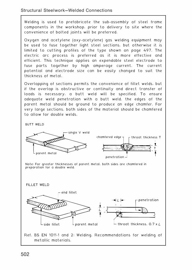
Welding is used to prefabricate the sub-assembly of steel frame
components in the workshop, prior to delivery to site where the
convenience of bolted joints will be preferred.
Oxygen and acetylene (oxy-acetylene) gas welding equipment may
be used to fuse together light steel sections, but otherwise it is
limited to cutting profiles of the type shown on page 497. The
electric arc process is preferred as it is more effective and
efficient. This technique applies an expendable steel electrode to
fuse parts together by high amperage current. The current
potential and electrode size can be easily changed to suit the
thickness of metal.
Overlapping of sections permits the convenience of fillet welds, but
if the overlap is obstructive or continuity and direct transfer of
loads is necessary, a butt weld will be specified. To ensure
adequate weld penetration with a butt weld, the edges of the
parent metal should be ground to produce an edge chamfer. For
very large sections, both sides of the material should be chamfered
to allow for double welds.
BUTT WELD
single V weld
chamfered edge throat thickness T
T
penetration
parent metal
Note: For greater thicknesses of parent metal, both sides are chamfered inpreparation for a double weld.
FILLET WELD
end fillet
side fillet parent metal throat thickness, 0.7 x
L
L
penetration
Ref. BS EN 1011-1 and 2: Welding. Recommendations for welding of
metallic materials.
502
Structural Steelwork---Welded Connections
Bolts are the preferred method for site assembly of framed building
components, although rivets have been popular in the past and will
be found when working on existing buildings. Cold driven and `pop'
rivets may be used for factory assembly of light steel frames such
as stud walling, but the traditional process of hot riveting
structural steel both in the workshop and on site has largely been
superseded for safety reasons and the convenience of other
practices.
Types of Bolt ~
1. Black Bolts ~ the least expensive and least precise type of
bolt, produced by forging with only the bolt and nut threads
machined. Clearance between the bolt shank and bolt hole is
about 2 mm, a tolerance that provides for ease of assembly.
However, this imprecision limits the application of these bolts
to direct bearing of components onto support brackets or
seating cleats.
2. Bright Bolts ~ also known as turned and fitted bolts. These
are machined under the bolt head and along the shank to
produce a close fit of 0„5 mm hole clearance. They are
specified where accuracy is paramount.
3. High Strength Friction Grip Bolts ~ also known as torque
bolts as they are tightened to a predetermined shank tension
by a torque controlled wrench. This procedure produces a
clamping force that transfers the connection by friction
between components and not by shear or bearing on the
bolts. These bolts are manufactured from high-yield steel. The
number of bolts used to make a connection is less than
otherwise required.
Refs.
BS 4190: ISO metric black hexagon bolts, screws and nuts.
Specification.
BS 3692: ISO metric precision hexagon bolts, screws and nuts.
Specification.
BS 4395 (2 parts): Specification for high strength friction grip bolts
and associated nuts and washers for structural engineering.
BS EN 14399 (6 parts): High strength structural bolting assemblies
for preloading.
503
Structural Steelwork -- Bolted Connections
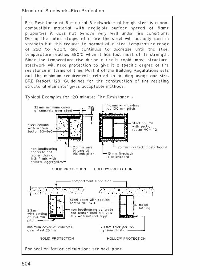
Fire Resistance of Structural Steelwork ~ although steel is a non-
combustible material with negligible surface spread of flame
properties it does not behave very well under fire conditions.
During the initial stages of a fire the steel will actually gain in
strength but this reduces to normal at a steel temperature range
of 250 to 400�C and continues to decrease until the steel
temperature reaches 550�C when it has lost most of its strength.
Since the temperature rise during a fire is rapid, most structural
steelwork will need protection to give it a specific degree of fire
resistance in terms of time. Part B of the Building Regulations sets
out the minimum requirements related to building usage and size,
BRE Report 128 `Guidelines for the construction of fire resisting
structural elements' gives acceptable methods.
Typical Examples for 120 minutes Fire Resistance ~
25 mm minimum coverof concrete over steel
1.6 mm wire bindingat 100 mm pitch
steel columnwith sectionfactor 90…140
25 mm firecheck plasterboard
15 mm firecheckplasterboard
25
min.
steel columnwith sectionfactor 90…140
non-loadbearingconcrete notleaner than a1: 2: 4 mix withnatural aggregates
2.3 mm wirebinding at150 mm pitch
SOLID PROTECTION
SOLID PROTECTION
compartment floor slab
steel beam with sectionfactor 90…140
non-loadbearing concretenot leaner than a 1: 2: 4mix with natural aggs.
metallathing
20 mm thick perlite-gypsum plaster
2.3 mmwire bindingat 150 mmpitch
minimum cover of concreteover steel 25 mm
HOLLOW PROTECTION
HOLLOW PROTECTION
For section factor calculations see next page.
504
Structural Steelwork---Fire Protection

Section Factors † these are criteria found in tabulated fire
protection data such as the Loss Prevention Certification Board's
Standards. These factors can be used to establish the minimum
thickness or cover of protective material for structural sections.
This interpretation is usually preferred by buildings insurance
companies, as it often provides a standard in excess of the building
regulations. Section factors are categorised: < 90, 90 † 140 and
> 140. They can be calculated by the following formula:
Section Factor = Hp/A (m�1)
Hp = Perimeter of section exposed to fire (m)
A = Cross sectional area of steel (m2) [see BS 4-1 or Structural
Steel Tables]
Examples:
Hp = (2 � 124„3) + (2 � 306„6) + 2(124„3 † 8) = 1„0944 m
A = 53„2 cm2 or 0„00532 m2
Section Factor, Hp/A = 1„0944/0„00532 = 205
As beam above, but 3 sides only exposed
fire protection
UB
compartment concretefloor, f.r. = 120 minutes
Hp = 124„3 + (2 � 306„6) + 2(124„3 † 8) = 0„9701 m
A = 53„2 cm2 or 0„00532 m2
Section Factor, Hp/A = 0„9701/0„00532 = 182
505
Structural Steelwork---Fire Protection
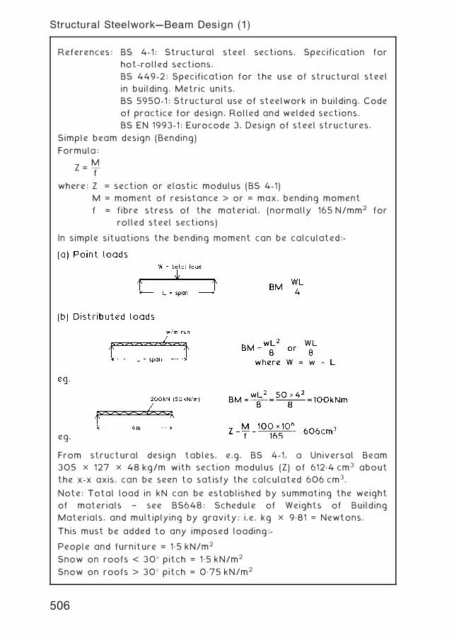
References: BS 4-1: Structural steel sections. Specification for
hot-rolled sections.
BS 449-2: Specification for the use of structural steel
in building. Metric units.
BS 5950-1: Structural use of steelwork in building. Code
of practice for design. Rolled and welded sections.
BS EN 1993-1: Eurocode 3. Design of steel structures.
Simple beam design (Bending)
Formula:
Z =Mf
where: Z = section or elastic modulus (BS 4-1)
M = moment of resistance > or = max. bending moment
f = fibre stress of the material, (normally 165 N/mm2 for
rolled steel sections)
In simple situations the bending moment can be calculated:-
eg.
From structural design tables, e.g. BS 4-1, a Universal Beam
305 � 127 � 48 kg/m with section modulus (Z) of 612„4 cm3 about
the x-x axis, can be seen to satisfy the calculated 606 cm3.
Note: Total load in kN can be established by summating the weight
of materials † see BS648: Schedule of Weights of Building
Materials, and multiplying by gravity; i.e. kg � 9„81 = Newtons.
This must be added to any imposed loading:-
People and furniture = 1„5 kN/m2
Snow on roofs < 30� pitch = 1„5 kN/m2
Snow on roofs > 30� pitch = 0„75 kN/m2
506
Structural Steelwork---Beam Design (1)
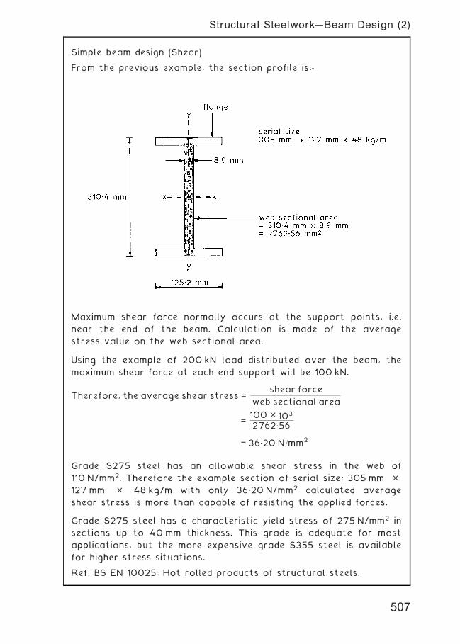
Simple beam design (Shear)
From the previous example, the section profile is:-
Maximum shear force normally occurs at the support points, i.e.
near the end of the beam. Calculation is made of the average
stress value on the web sectional area.
Using the example of 200 kN load distributed over the beam, the
maximum shear force at each end support will be 100 kN.
Therefore, the average shear stress =shear force
web sectional area
=100 � 103
2762„56
= 36„20 N=mm2
Grade S275 steel has an allowable shear stress in the web of
110 N/mm2. Therefore the example section of serial size: 305 mm �127 mm � 48 kg/m with only 36„20 N/mm2 calculated average
shear stress is more than capable of resisting the applied forces.
Grade S275 steel has a characteristic yield stress of 275 N/mm2 in
sections up to 40 mm thickness. This grade is adequate for most
applications, but the more expensive grade S355 steel is available
for higher stress situations.
Ref. BS EN 10025: Hot rolled products of structural steels.
507
Structural Steelwork---Beam Design (2)
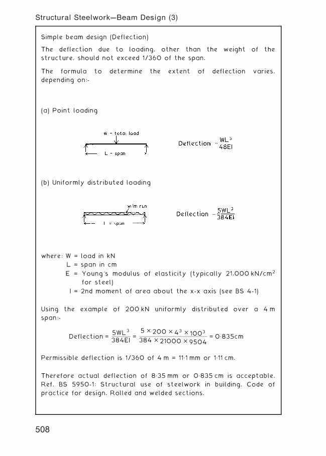
Simple beam design (Deflection)
The deflection due to loading, other than the weight of the
structure, should not exceed 1/360 of the span.
The formula to determine the extent of deflection varies,
depending on:-
(a) Point loading
(b) Uniformly distributed loading
where: W = load in kN
L = span in cm
E = Young's modulus of elasticity (typically 21,000 kN/cm2
for steel)
I = 2nd moment of area about the x-x axis (see BS 4-1)
Using the example of 200 kN uniformly distributed over a 4 m
span:-
Deflection =5WL3
384EI=
5 � 200 � 43 � 1003
384 � 21000 � 9504= 0„835cm
Permissible deflection is 1/360 of 4 m = 11„1 mm or 1„11 cm.
Therefore actual deflection of 8„35 mm or 0„835 cm is acceptable.
Ref. BS 5950-1: Structural use of steelwork in building. Code of
practice for design. Rolled and welded sections.
508
Structural Steelwork---Beam Design (3)
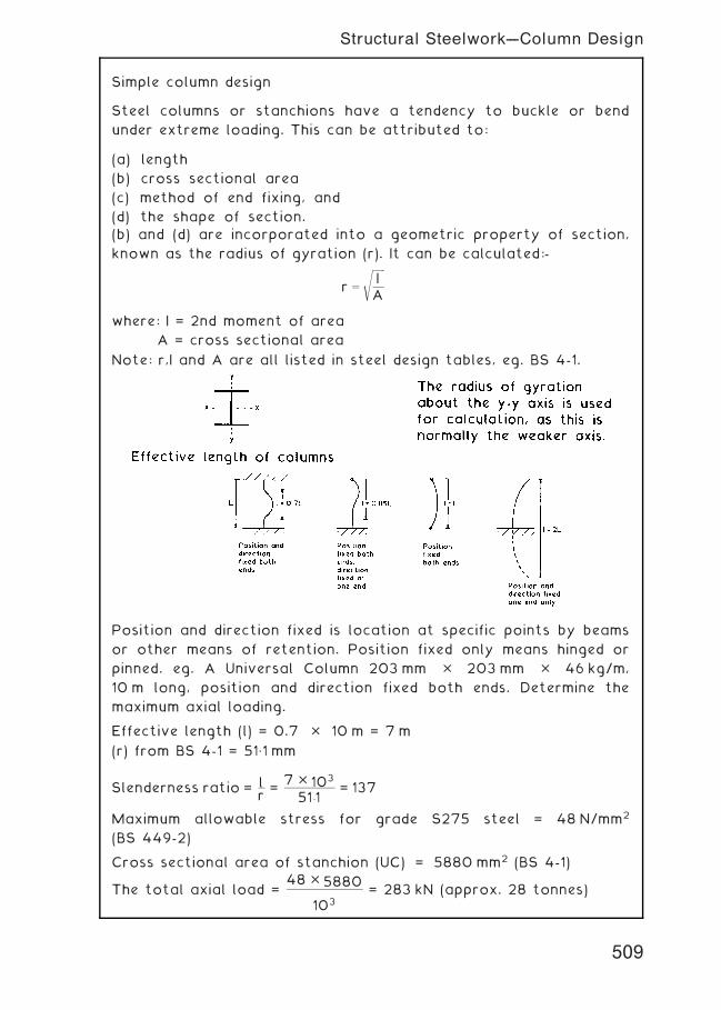
Simple column design
Steel columns or stanchions have a tendency to buckle or bend
under extreme loading. This can be attributed to:
(a) length
(b) cross sectional area
(c) method of end fixing, and
(d) the shape of section.
(b) and (d) are incorporated into a geometric property of section,
known as the radius of gyration (r). It can be calculated:-
r ¼
ffiffiffiffiffiffi
IA
s
where: I = 2nd moment of area
A = cross sectional area
Note: r,I and A are all listed in steel design tables, eg. BS 4-1.
Position and direction fixed is location at specific points by beams
or other means of retention. Position fixed only means hinged or
pinned. eg. A Universal Column 203 mm � 203 mm � 46 kg/m,
10 m long, position and direction fixed both ends. Determine the
maximum axial loading.
Effective length (l) = 0.7 � 10 m = 7 m
(r) from BS 4-1 = 51„1 mm
Slenderness ratio = lr=
7 � 103
51:1= 137
Maximum allowable stress for grade S275 steel = 48 N/mm2
(BS 449-2)
Cross sectional area of stanchion (UC) = 5880 mm2 (BS 4-1)
The total axial load =48 � 5880
103= 283 kN (approx. 28 tonnes)
509
Structural Steelwork---Column Design
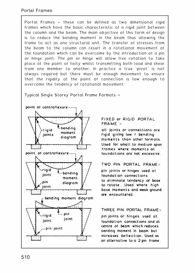
Portal Frames ~ these can be defined as two dimensional rigid
frames which have the basic characteristic of a rigid joint between
the column and the beam. The main objective of this form of design
is to reduce the bending moment in the beam thus allowing the
frame to act as one structural unit. The transfer of stresses from
the beam to the column can result in a rotational movement at
the foundation which can be overcome by the introduction of a pin
or hinge joint. The pin or hinge will allow free rotation to take
place at the point of fixity whilst transmitting both load and shear
from one member to another. In practice a true `pivot' is not
always required but there must be enough movement to ensure
that the rigidity at the point of connection is low enough to
overcome the tendency of rotational movement.
510
Portal Frames
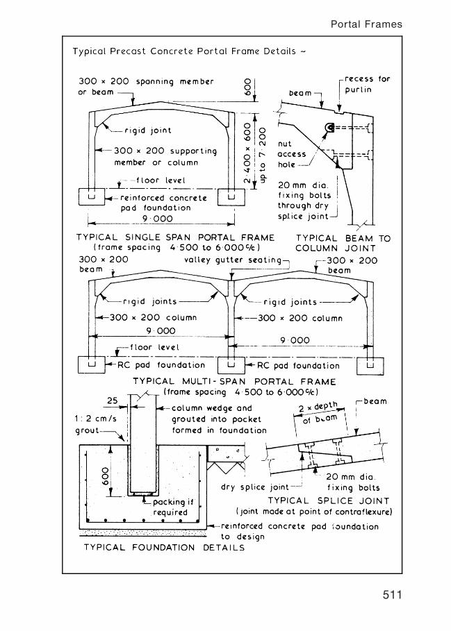
511
Portal Frames
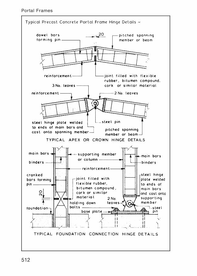
512
Portal Frames
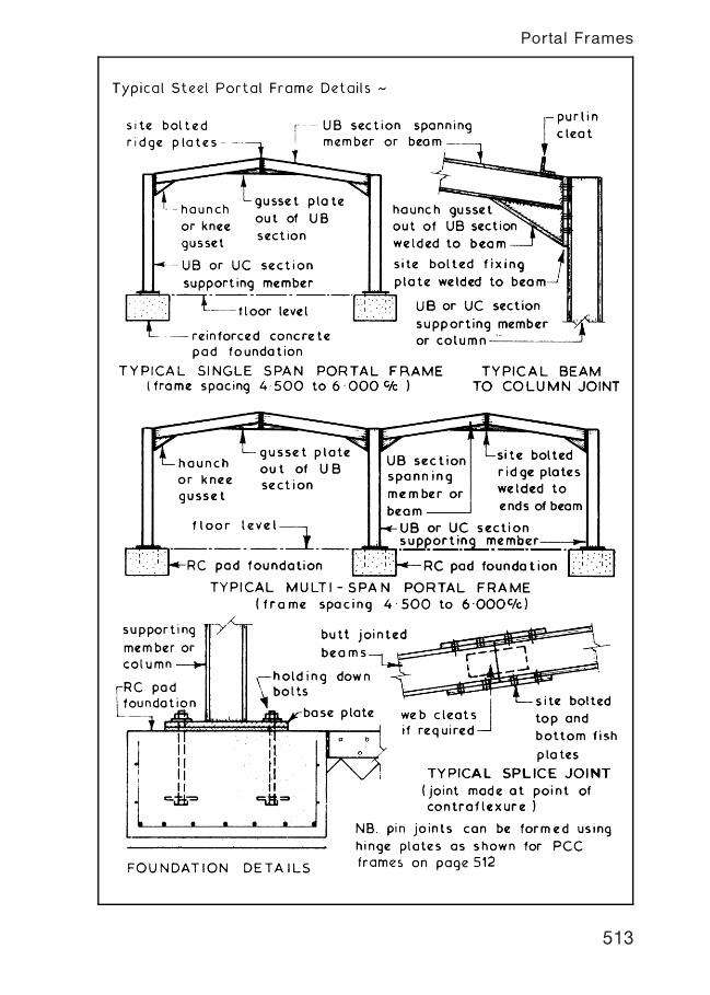
513
Portal Frames
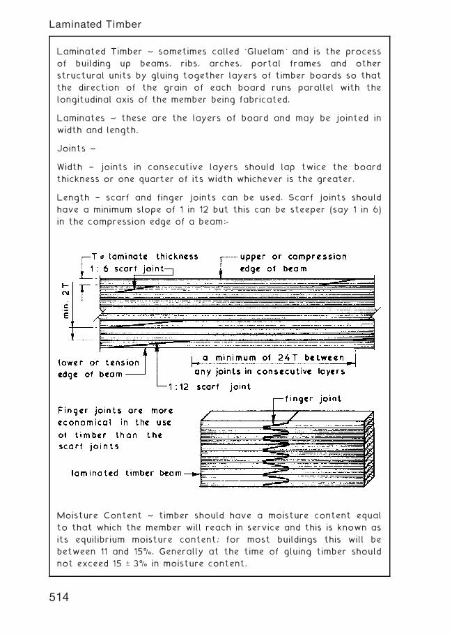
Laminated Timber ~ sometimes called `Gluelam' and is the process
of building up beams, ribs, arches, portal frames and other
structural units by gluing together layers of timber boards so that
the direction of the grain of each board runs parallel with the
longitudinal axis of the member being fabricated.
Laminates ~ these are the layers of board and may be jointed in
width and length.
Joints ~
Width † joints in consecutive layers should lap twice the board
thickness or one quarter of its width whichever is the greater.
Length † scarf and finger joints can be used. Scarf joints should
have a minimum slope of 1 in 12 but this can be steeper (say 1 in 6)
in the compression edge of a beam:-
Moisture Content ~ timber should have a moisture content equal
to that which the member will reach in service and this is known as
its equilibrium moisture content; for most buildings this will be
between 11 and 15%. Generally at the time of gluing timber should
not exceed 15 – 3% in moisture content.
514
Laminated Timber
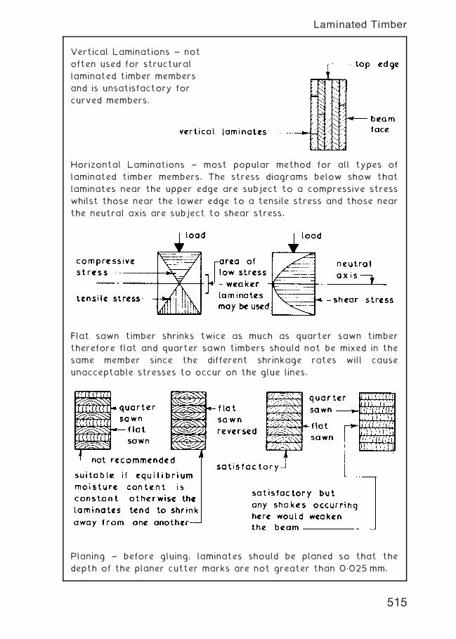
Vertical Laminations ~ not
often used for structural
laminated timber members
and is unsatisfactory for
curved members.
Horizontal Laminations ~ most popular method for all types of
laminated timber members. The stress diagrams below show that
laminates near the upper edge are subject to a compressive stress
whilst those near the lower edge to a tensile stress and those near
the neutral axis are subject to shear stress.
Flat sawn timber shrinks twice as much as quarter sawn timber
therefore flat and quarter sawn timbers should not be mixed in the
same member since the different shrinkage rates will cause
unacceptable stresses to occur on the glue lines.
Planing ~ before gluing, laminates should be planed so that the
depth of the planer cutter marks are not greater than 0„025 mm.
515
Laminated Timber
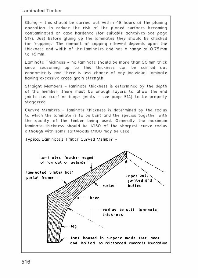
Gluing ~ this should be carried out within 48 hours of the planing
operation to reduce the risk of the planed surfaces becoming
contaminated or case hardened (for suitable adhesives see page
517). Just before gluing up the laminates they should be checked
for `cupping.' The amount of cupping allowed depends upon the
thickness and width of the laminates and has a range of 0„75 mm
to 1„5 mm.
Laminate Thickness ~ no laminate should be more than 50 mm thick
since seasoning up to this thickness can be carried out
economically and there is less chance of any individual laminate
having excessive cross grain strength.
Straight Members † laminate thickness is determined by the depth
of the member, there must be enough layers to allow the end
joints (i.e. scarf or finger joints † see page 514) to be properly
staggered.
Curved Members † laminate thickness is determined by the radius
to which the laminate is to be bent and the species together with
the quality of the timber being used. Generally the maximum
laminate thickness should be 1/150 of the sharpest curve radius
although with some softwoods 1/100 may be used.
516
Laminated Timber
Adhesives ~ although timber laminates are carefully machined, the
minimum of cupping permitted and efficient cramping methods
employed it is not always possible to obtain really tight joints
between the laminates. One of the important properties of the
adhesive is therefore that it should be gap filling. The maximum
permissible gap being 1.25 mm.
There are four adhesives suitable for laminated timber work which
have the necessary gap filling property and they are namely:-
1. Casein † the protein in milk, extracted by coagulation and
precipitation. It is a cold setting adhesive in the form of a
powder which is mixed with water, it has a tendency to stain
timber and is only suitable for members used in dry conditions
of service.
2. Urea Formaldehyde † this is a cold setting resin glue
formulated to MR/GF (moisture resistant/gap filling). Although
moisture resistant it is not suitable for prolonged exposure in
wet conditions and there is a tendency for the glue to lose its
strength in temperatures above 40�C such as when exposed to
direct sunlight. The use of this adhesive is usually confined to
members used in dry, unexposed conditions of service. This
adhesive will set under temperatures down to 10�C.
3. Resorcinol Formaldehyde † this is a cold setting glue
formulated to WBP/GF (weather and boilproof/gap filling). It is
suitable for members used in external situations but is
relatively expensive. This adhesive will set under temperatures
down to 15�C and does not lose its strength at high
temperatures.
4. Phenol Formaldehyde † this is a similar glue to resorcinol
formaldehyde but is a warm setting adhesive requiring a
temperature of above 86�C in order to set. Phenol/resorcinol
formaldehyde is an alternative, having similar properties to,
but less expensive than resorcinol formaldehyde. PRF needs a
setting temperature of at least 23�C.
Preservative Treatment † this can be employed if required,
provided that the pressure impregnated preservative used is
selected with regard to the adhesive being employed. See also
page 427.
Ref. BS EN 301: Adhesives, phenolic and aminoplastic, for load-
bearing timber structures. Classification and performance
requirements.
517
Laminated Timber
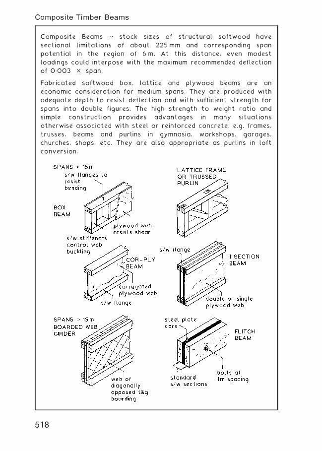
Composite Beams ~ stock sizes of structural softwood have
sectional limitations of about 225 mm and corresponding span
potential in the region of 6 m. At this distance, even modest
loadings could interpose with the maximum recommended deflection
of 0„003 � span.
Fabricated softwood box, lattice and plywood beams are an
economic consideration for medium spans. They are produced with
adequate depth to resist deflection and with sufficient strength for
spans into double figures. The high strength to weight ratio and
simple construction provides advantages in many situations
otherwise associated with steel or reinforced concrete, e.g. frames,
trusses, beams and purlins in gymnasia, workshops, garages,
churches, shops, etc. They are also appropriate as purlins in loft
conversion.
518
Composite Timber Beams
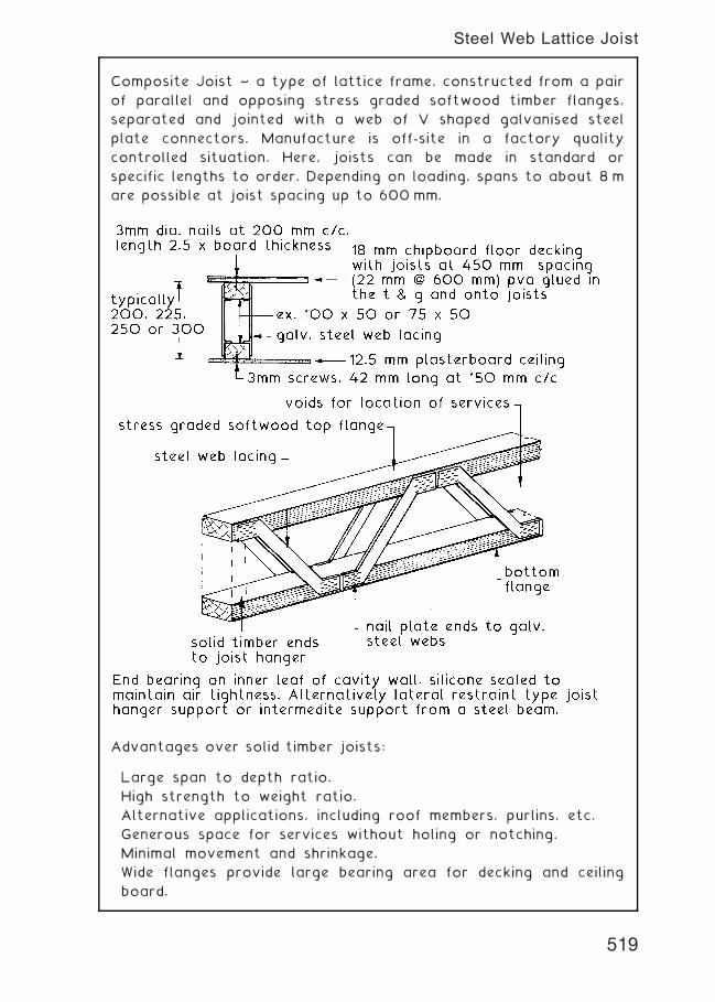
Composite Joist ~ a type of lattice frame, constructed from a pair
of parallel and opposing stress graded softwood timber flanges,
separated and jointed with a web of V shaped galvanised steel
plate connectors. Manufacture is off-site in a factory quality
controlled situation. Here, joists can be made in standard or
specific lengths to order. Depending on loading, spans to about 8 m
are possible at joist spacing up to 600 mm.
Advantages over solid timber joists:
Large span to depth ratio.
High strength to weight ratio.
Alternative applications, including roof members, purlins, etc.
Generous space for services without holing or notching.
Minimal movement and shrinkage.
Wide flanges provide large bearing area for decking and ceiling
board.
519
Steel Web Lattice Joist
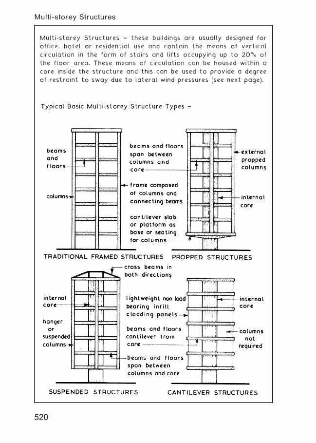
Multi-storey Structures ~ these buildings are usually designed for
office, hotel or residential use and contain the means of vertical
circulation in the form of stairs and lifts occupying up to 20% of
the floor area. These means of circulation can be housed within a
core inside the structure and this can be used to provide a degree
of restraint to sway due to lateral wind pressures (see next page).
520
Multi-storey Structures
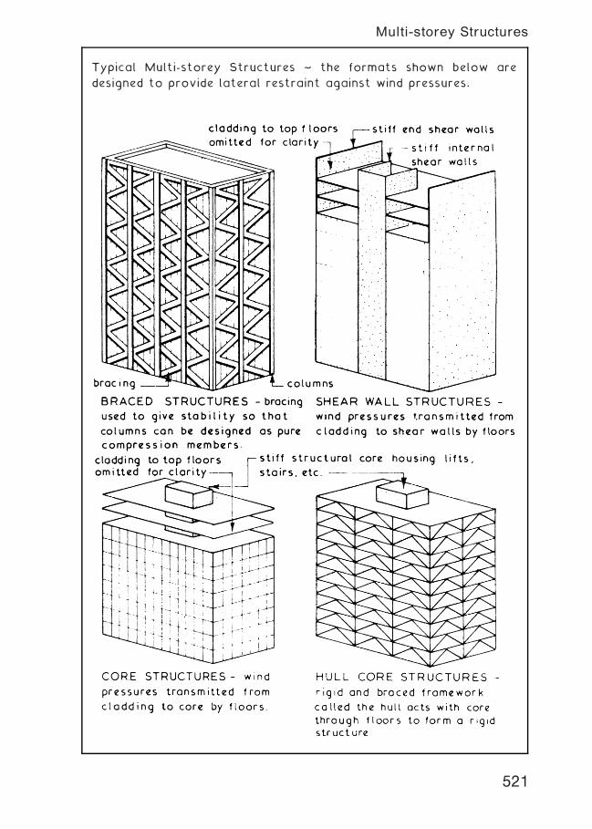
Typical Multi-storey Structures ~ the formats shown below are
designed to provide lateral restraint against wind pressures.
521
Multi-storey Structures
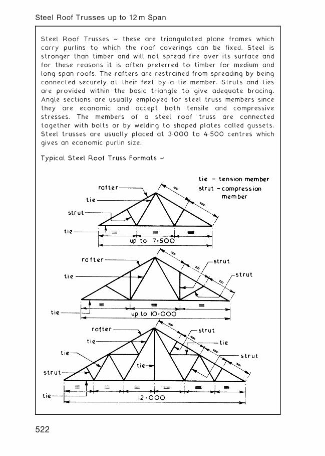
Steel Roof Trusses ~ these are triangulated plane frames which
carry purlins to which the roof coverings can be fixed. Steel is
stronger than timber and will not spread fire over its surface and
for these reasons it is often preferred to timber for medium and
long span roofs. The rafters are restrained from spreading by being
connected securely at their feet by a tie member. Struts and ties
are provided within the basic triangle to give adequate bracing.
Angle sections are usually employed for steel truss members since
they are economic and accept both tensile and compressive
stresses. The members of a steel roof truss are connected
together with bolts or by welding to shaped plates called gussets.
Steel trusses are usually placed at 3„000 to 4„500 centres which
gives an economic purlin size.
522
Steel Roof Trusses up to 12m Span
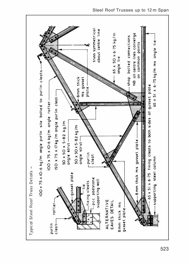
523
Steel Roof Trusses up to 12m Span
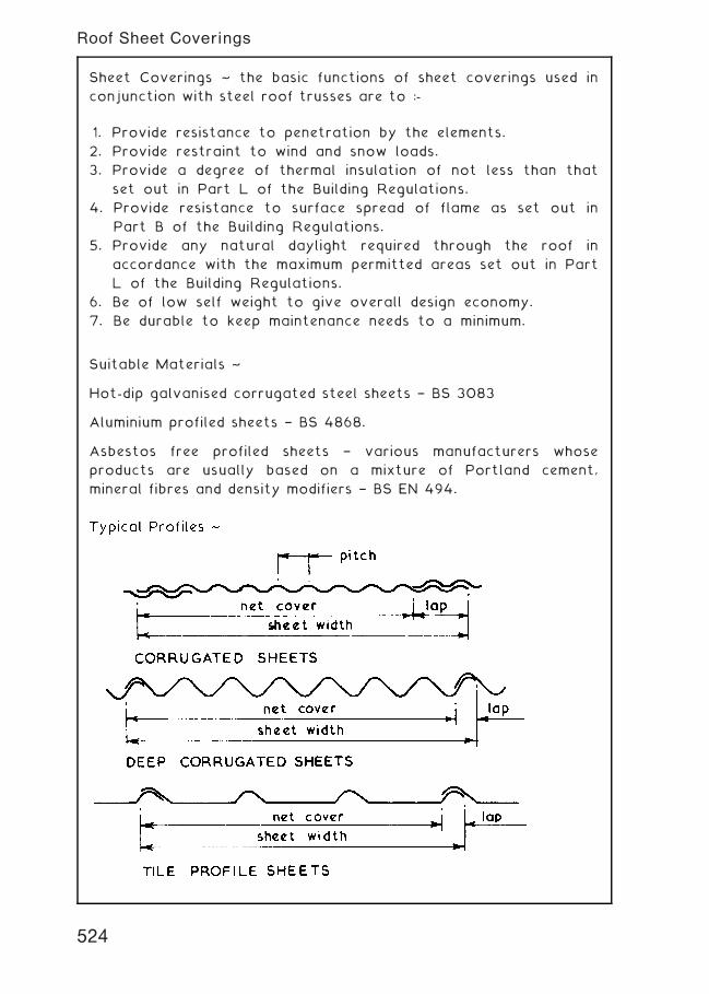
Sheet Coverings ~ the basic functions of sheet coverings used in
conjunction with steel roof trusses are to :-
1. Provide resistance to penetration by the elements.
2. Provide restraint to wind and snow loads.
3. Provide a degree of thermal insulation of not less than that
set out in Part L of the Building Regulations.
4. Provide resistance to surface spread of flame as set out in
Part B of the Building Regulations.
5. Provide any natural daylight required through the roof in
accordance with the maximum permitted areas set out in Part
L of the Building Regulations.
6. Be of low self weight to give overall design economy.
7. Be durable to keep maintenance needs to a minimum.
Suitable Materials ~
Hot-dip galvanised corrugated steel sheets † BS 3083
Aluminium profiled sheets † BS 4868.
Asbestos free profiled sheets † various manufacturers whose
products are usually based on a mixture of Portland cement,
mineral fibres and density modifiers † BS EN 494.
524
Roof Sheet Coverings
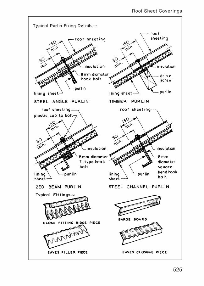
525
Roof Sheet Coverings
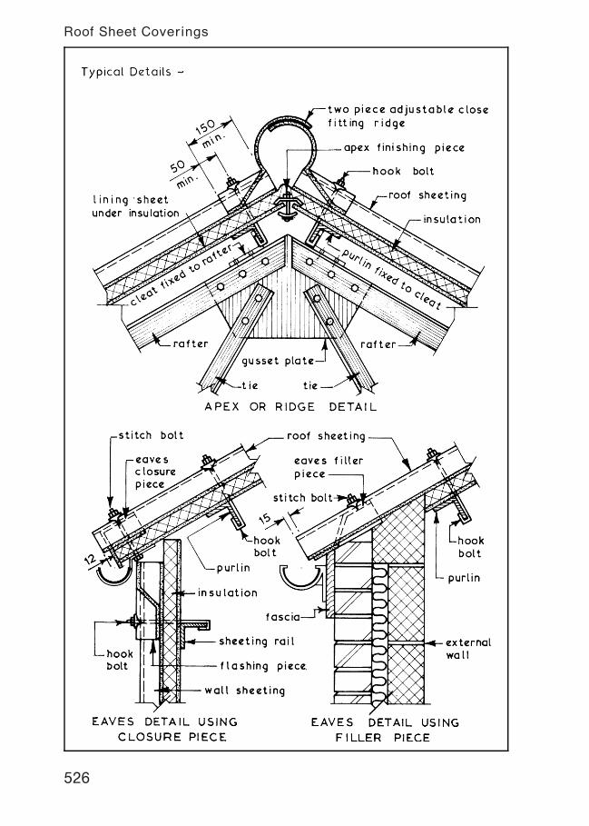
526
Roof Sheet Coverings
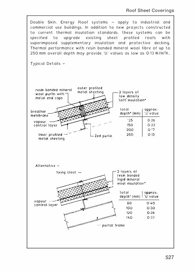
Double Skin, Energy Roof systems ~ apply to industrial and
commercial use buildings. In addition to new projects constructed
to current thermal insulation standards, these systems can be
specified to upgrade existing sheet profiled roofs with
superimposed supplementary insulation and protective decking.
Thermal performance with resin bonded mineral wool fibre of up to
250 mm overall depth may provide `U' values as low as 0„13 W/m2K.
Typical Details ~
527
Roof Sheet Coverings
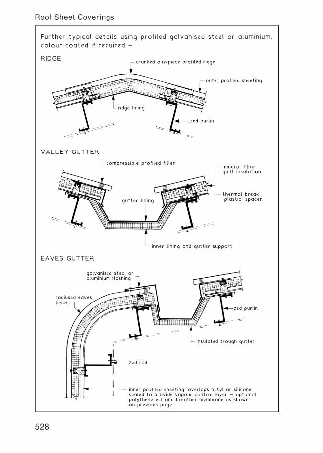
Further typical details using profiled galvanised steel or aluminium,
colour coated if required ~
RIDGEcranked one-piece profiled ridge
zed purlin
ridge lining
outer profiled sheeting
VALLEY GUTTER
compressible profiled fillermineral fibrequilt insulation
thermal break`plastic' spacer
inner lining and gutter support
gutter lining
EAVES GUTTER
radiused eavespiece
galvanised steel oraluminium flashing
zed purlin
zed rail
inner profiled sheeting, overlaps butyl or siliconesealed to provide vapour control layer … optionalpolythene vcl and breather membrane as shownon previous page
insulated trough gutter
528
Roof Sheet Coverings
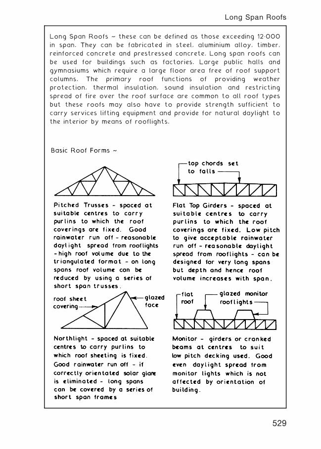
Long Span Roofs ~ these can be defined as those exceeding 12„000
in span. They can be fabricated in steel, aluminium alloy, timber,
reinforced concrete and prestressed concrete. Long span roofs can
be used for buildings such as factories. Large public halls and
gymnasiums which require a large floor area free of roof support
columns. The primary roof functions of providing weather
protection, thermal insulation, sound insulation and restricting
spread of fire over the roof surface are common to all roof types
but these roofs may also have to provide strength sufficient to
carry services lifting equipment and provide for natural daylight to
the interior by means of rooflights.
529
Long Span Roofs
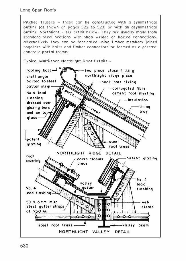
Pitched Trusses ~ these can be constructed with a symmetrical
outline (as shown on pages 522 to 523) or with an asymmetrical
outline (Northlight † see detail below). They are usually made from
standard steel sections with shop welded or bolted connections,
alternatively they can be fabricated using timber members joined
together with bolts and timber connectors or formed as a precast
concrete portal frame.
530
Long Span Roofs
Monitor
Roofs
~these
are
basically
aflat
roof
with
raised
gla
zed
port
ions
called
monitors
which
form
sa
roofhaving
auniform
distributio
nofdaylight
with
no
sola
rgla
repro
blems
irre
spective
oforientatio
nand
a
roof
with
easy
access
for
maintenance.
These
roofs
can
be
constru
cted
with
light
long
span
girders
support
ing
the
monitor
frames,cra
nked
welded
beams
following
the
pro
file
ofthe
roofor
they
can
be
ofa
pre
cast
concre
te
port
alframe
form
at.
531
Long Span Roofs
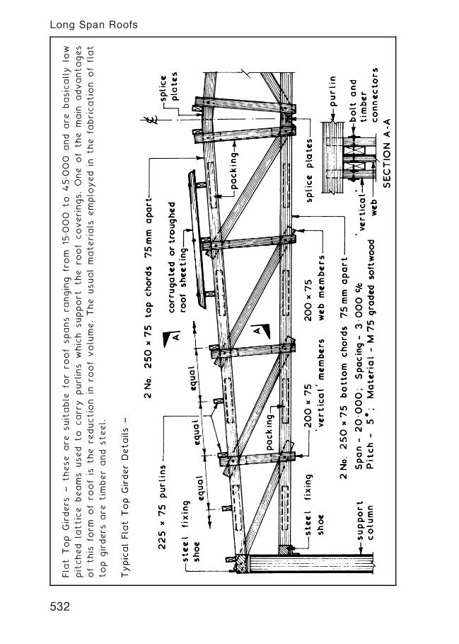
Fla
tTop
Girders
~these
are
suitable
for
roofspans
ranging
from
15„0
00
to
45„0
00
and
are
basically
low
pitched
lattice
beams
used
to
carr
ypurlins
which
support
the
roof
coverings.One
ofthe
main
advantages
ofthis
form
ofro
ofis
the
reductio
nin
roofvolume.The
usualmaterials
emplo
yed
inthe
fabricatio
nofflat
top
girders
are
tim
berand
steel.
532
Long Span Roofs
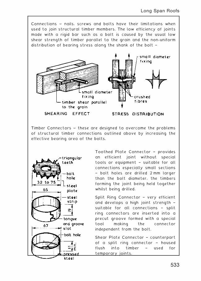
Connections ~ nails, screws and bolts have their limitations when
used to join structural timber members. The low efficiency of joints
made with a rigid bar such as a bolt is caused by the usual low
shear strength of timber parallel to the grain and the non-uniform
distribution of bearing stress along the shank of the bolt †
Timber Connectors ~ these are designed to overcome the problems
of structural timber connections outlined above by increasing the
effective bearing area of the bolts.
Toothed Plate Connector † provides
an efficient joint without special
tools or equipment † suitable for all
connections especially small sections
† bolt holes are drilled 2 mm larger
than the bolt diameter, the timbers
forming the joint being held together
whilst being drilled.
Split Ring Connector † very efficient
and develops a high joint strength †
suitable for all connections † split
ring connectors are inserted into a
precut groove formed with a special
tool making the connector
independent from the bolt.
Shear Plate Connector † counterpart
of a split ring connector † housed
flush into timber † used for
temporary joints.
533
Long Span Roofs
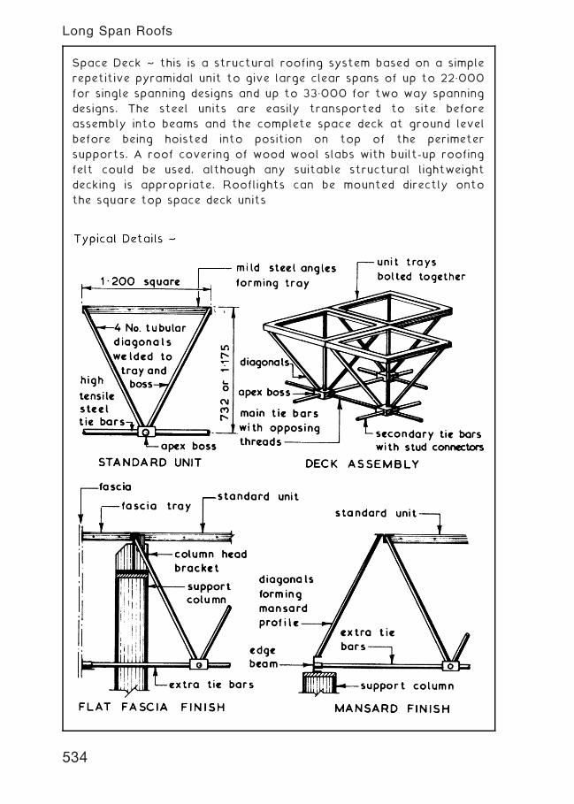
Space Deck ~ this is a structural roofing system based on a simple
repetitive pyramidal unit to give large clear spans of up to 22„000
for single spanning designs and up to 33„000 for two way spanning
designs. The steel units are easily transported to site before
assembly into beams and the complete space deck at ground level
before being hoisted into position on top of the perimeter
supports. A roof covering of wood wool slabs with built-up roofing
felt could be used, although any suitable structural lightweight
decking is appropriate. Rooflights can be mounted directly onto
the square top space deck units
534
Long Span Roofs
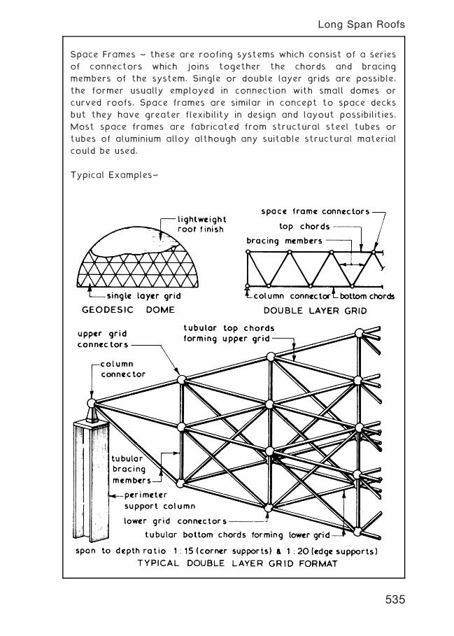
Space Frames ~ these are roofing systems which consist of a series
of connectors which joins together the chords and bracing
members of the system. Single or double layer grids are possible,
the former usually employed in connection with small domes or
curved roofs. Space frames are similar in concept to space decks
but they have greater flexibility in design and layout possibilities.
Most space frames are fabricated from structural steel tubes or
tubes of aluminium alloy although any suitable structural material
could be used.
Typical Examples~
535
Long Span Roofs
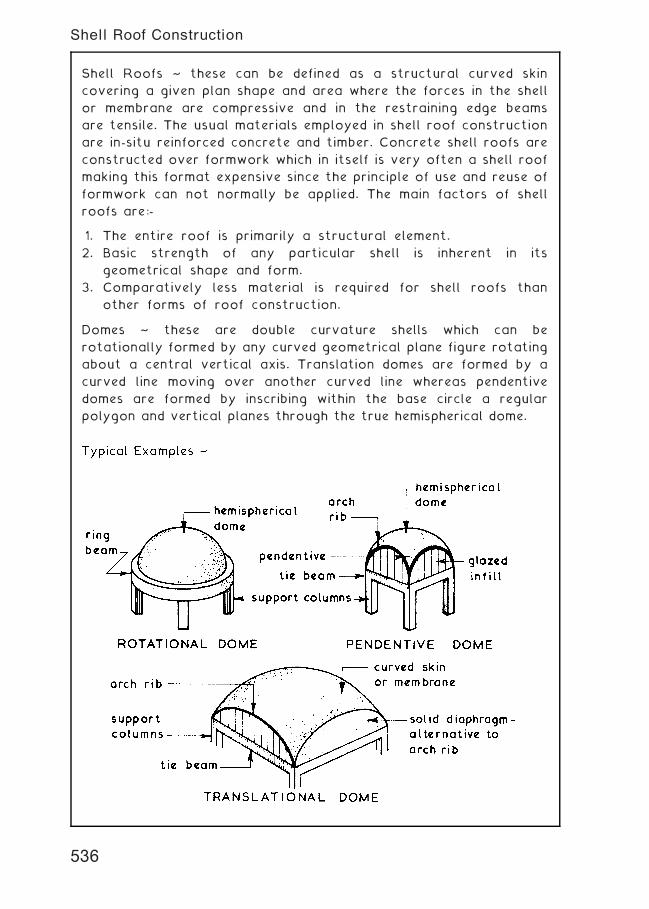
Shell Roofs ~ these can be defined as a structural curved skin
covering a given plan shape and area where the forces in the shell
or membrane are compressive and in the restraining edge beams
are tensile. The usual materials employed in shell roof construction
are in-situ reinforced concrete and timber. Concrete shell roofs are
constructed over formwork which in itself is very often a shell roof
making this format expensive since the principle of use and reuse of
formwork can not normally be applied. The main factors of shell
roofs are:-
1. The entire roof is primarily a structural element.
2. Basic strength of any particular shell is inherent in its
geometrical shape and form.
3. Comparatively less material is required for shell roofs than
other forms of roof construction.
Domes ~ these are double curvature shells which can be
rotationally formed by any curved geometrical plane figure rotating
about a central vertical axis. Translation domes are formed by a
curved line moving over another curved line whereas pendentive
domes are formed by inscribing within the base circle a regular
polygon and vertical planes through the true hemispherical dome.
536
Shell Roof Construction
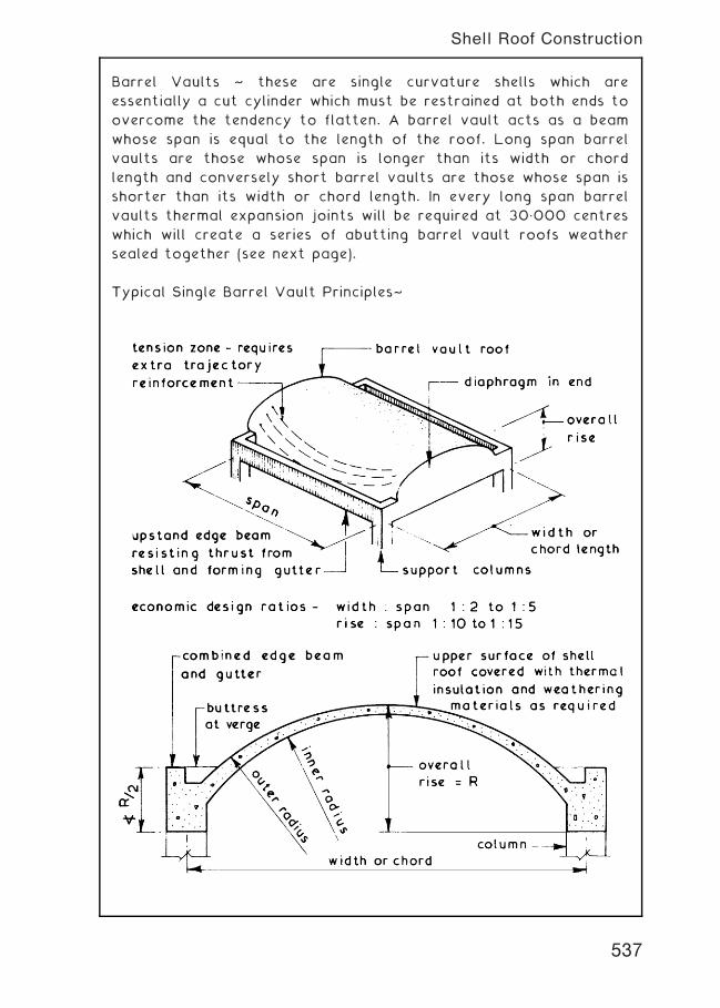
Barrel Vaults ~ these are single curvature shells which are
essentially a cut cylinder which must be restrained at both ends to
overcome the tendency to flatten. A barrel vault acts as a beam
whose span is equal to the length of the roof. Long span barrel
vaults are those whose span is longer than its width or chord
length and conversely short barrel vaults are those whose span is
shorter than its width or chord length. In every long span barrel
vaults thermal expansion joints will be required at 30„000 centres
which will create a series of abutting barrel vault roofs weather
sealed together (see next page).
Typical Single Barrel Vault Principles~
537
Shell Roof Construction
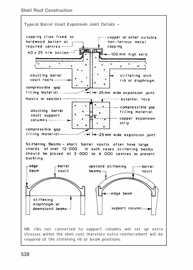
NB. ribs not connected to support columns will set up extra
stresses within the shell roof therefore extra reinforcement will be
required at the stiffening rib or beam positions.
538
Shell Roof Construction
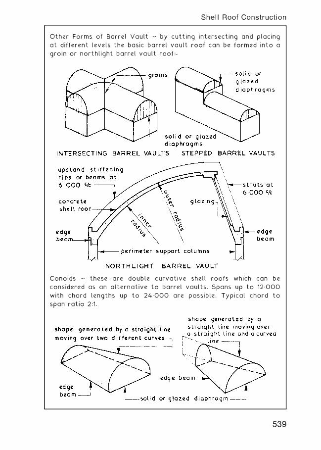
Other Forms of Barrel Vault ~ by cutting intersecting and placing
at different levels the basic barrel vault roof can be formed into a
groin or northlight barrel vault roof:-
Conoids ~ these are double curvative shell roofs which can be
considered as an alternative to barrel vaults. Spans up to 12„000
with chord lengths up to 24„000 are possible. Typical chord to
span ratio 2:1.
539
Shell Roof Construction
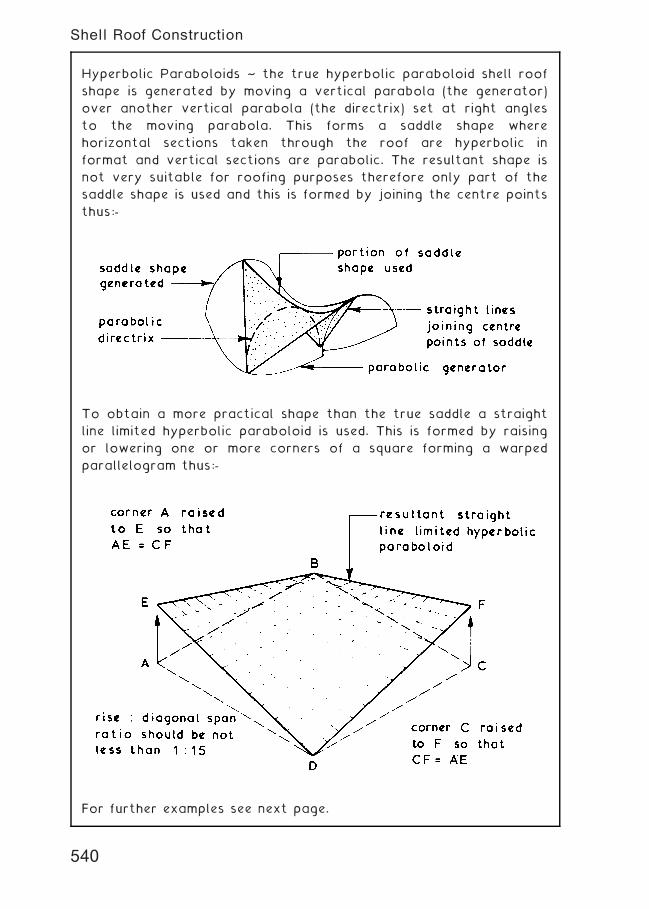
Hyperbolic Paraboloids ~ the true hyperbolic paraboloid shell roof
shape is generated by moving a vertical parabola (the generator)
over another vertical parabola (the directrix) set at right angles
to the moving parabola. This forms a saddle shape where
horizontal sections taken through the roof are hyperbolic in
format and vertical sections are parabolic. The resultant shape is
not very suitable for roofing purposes therefore only part of the
saddle shape is used and this is formed by joining the centre points
thus:-
To obtain a more practical shape than the true saddle a straight
line limited hyperbolic paraboloid is used. This is formed by raising
or lowering one or more corners of a square forming a warped
parallelogram thus:-
For further examples see next page.
540
Shell Roof Construction
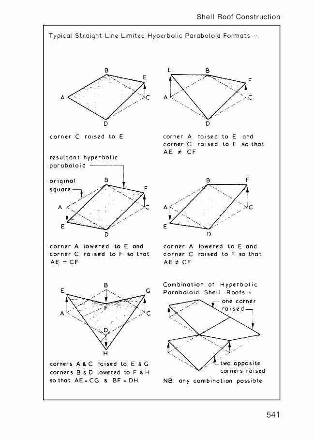
Typical Straight Line Limited Hyperbolic Paraboloid Formats ~
541
Shell Roof Construction
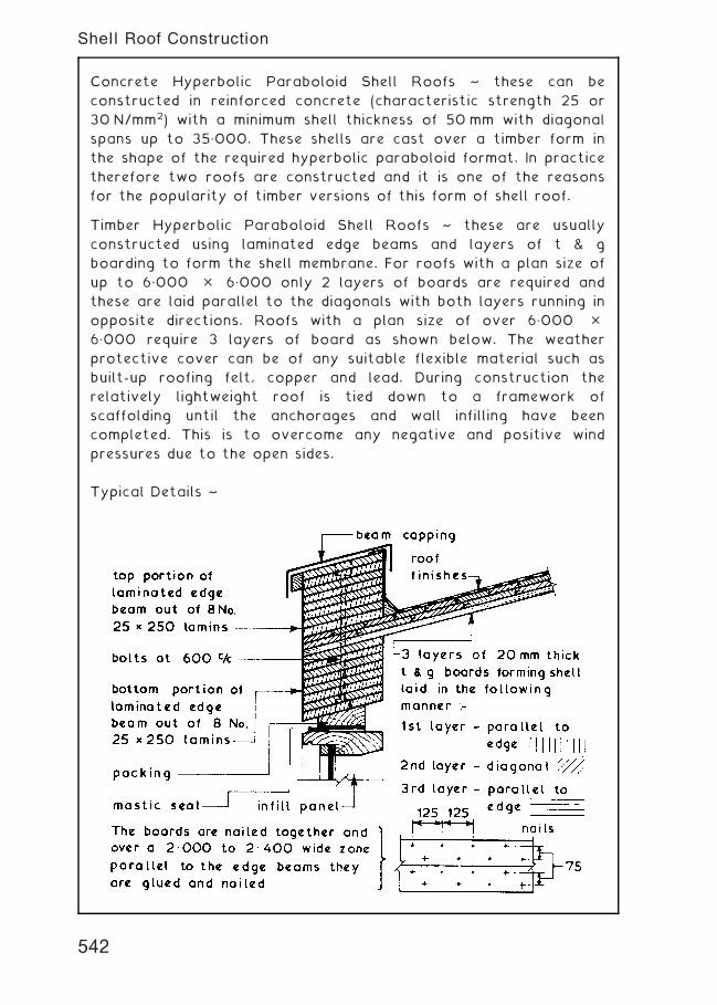
Concrete Hyperbolic Paraboloid Shell Roofs ~ these can be
constructed in reinforced concrete (characteristic strength 25 or
30 N/mm2) with a minimum shell thickness of 50 mm with diagonal
spans up to 35„000. These shells are cast over a timber form in
the shape of the required hyperbolic paraboloid format. In practice
therefore two roofs are constructed and it is one of the reasons
for the popularity of timber versions of this form of shell roof.
Timber Hyperbolic Paraboloid Shell Roofs ~ these are usually
constructed using laminated edge beams and layers of t & g
boarding to form the shell membrane. For roofs with a plan size of
up to 6„000 � 6„000 only 2 layers of boards are required and
these are laid parallel to the diagonals with both layers running in
opposite directions. Roofs with a plan size of over 6„000 �6„000 require 3 layers of board as shown below. The weather
protective cover can be of any suitable flexible material such as
built-up roofing felt, copper and lead. During construction the
relatively lightweight roof is tied down to a framework of
scaffolding until the anchorages and wall infilling have been
completed. This is to overcome any negative and positive wind
pressures due to the open sides.
Typical Details ~
542
Shell Roof Construction
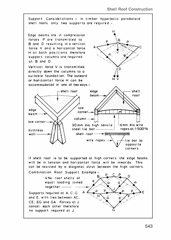
543
Shell Roof Construction
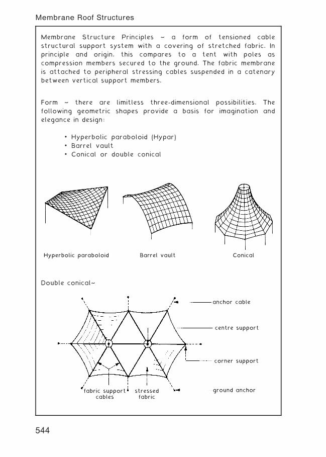
Membrane Structure Principles ~ a form of tensioned cable
structural support system with a covering of stretched fabric. In
principle and origin, this compares to a tent with poles as
compression members secured to the ground. The fabric membrane
is attached to peripheral stressing cables suspended in a catenary
between vertical support members.
Form ~ there are limitless three-dimensional possibilities. The
following geometric shapes provide a basis for imagination and
elegance in design:
• Hyperbolic paraboloid (Hypar)
• Barrel vault
• Conical or double conical
Hyperbolic paraboloid Barrel vault Conical
Double conical~
anchor cable
centre support
corner support
ground anchorfabric supportcables
stressedfabric
544
Membrane Roof Structures

Simple support structure as viewed from the underside ~
vertical compression member
stressed fabric
reinforced gussets
peripheral support or ties
tensioned fabricsupport cables
tensioned horizontalcables securedcentrally to avertical supportplate
Fabric ~ has the advantages of requiring minimal support,
opportunity for architectural expression in colour and geometry
and a translucent quality that provides an outside feel inside,
whilst combining shaded cover from the sun and shelter from rain.
Applications are generally attachments as a feature to entrances
and function areas in prominent buildings, notably sports venues,
airports and convention centres.
Materials ~ historically, animal hides were the first materials used
for tensile fabric structures, but more recently woven fibres of
hemp, flax or other natural yarns have evolved as canvas.
Contemporary synthetic materials have a plastic coating on a
fibrous base. These include polyvinyl chloride (PVC) on polyester
fibres, silicone on glass fibres and polytetrafluorethylene (PTFE) on
glass fibres. Design life is difficult to estimate, as it will depend
very much on type of exposure. Previous use of these materials
would indicate that at least 20 years is anticipated, with an excess
of 30 years being likely. Jointing can be by fusion welding of
plastics, bonding with silicone adhesives and stitching with glass
threads.
545
Membrane Roof Structures
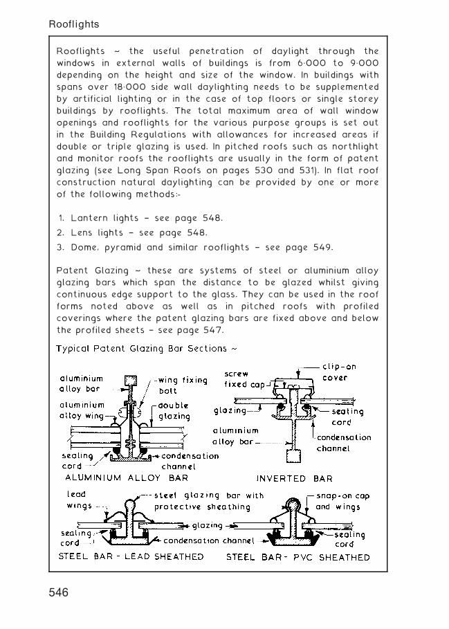
Rooflights ~ the useful penetration of daylight through the
windows in external walls of buildings is from 6„000 to 9„000
depending on the height and size of the window. In buildings with
spans over 18„000 side wall daylighting needs to be supplemented
by artificial lighting or in the case of top floors or single storey
buildings by rooflights. The total maximum area of wall window
openings and rooflights for the various purpose groups is set out
in the Building Regulations with allowances for increased areas if
double or triple glazing is used. In pitched roofs such as northlight
and monitor roofs the rooflights are usually in the form of patent
glazing (see Long Span Roofs on pages 530 and 531). In flat roof
construction natural daylighting can be provided by one or more
of the following methods:-
1. Lantern lights † see page 548.
2. Lens lights † see page 548.
3. Dome, pyramid and similar rooflights † see page 549.
Patent Glazing ~ these are systems of steel or aluminium alloy
glazing bars which span the distance to be glazed whilst giving
continuous edge support to the glass. They can be used in the roof
forms noted above as well as in pitched roofs with profiled
coverings where the patent glazing bars are fixed above and below
the profiled sheets † see page 547.
546
Rooflights
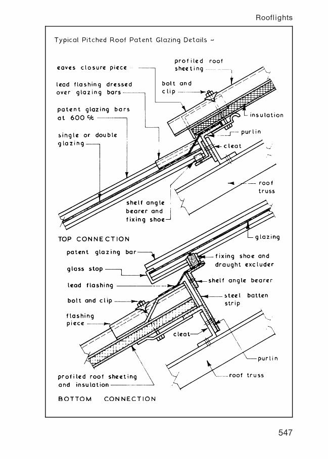
547
Rooflights
Lantern Lights ~ these are a form of rooflight used in conjuction
with flat roofs. They consist of glazed vertical sides and fully
glazed pitched roof which is usually hipped at both ends. Part of
the glazed upstand sides is usually formed as an opening light or
alternatively glazed with louvres to provide a degree of
controllable ventilation. They can be constructed of timber, metal
or a combination of these two materials. Lantern lights in the
context of new buildings have been generally superseded by the
various forms of dome light (see next page)
Lens Lights ~ these are small square or round blocks of
translucent toughened glass especially designed for casting into
concrete and are suitable for use in flat roofs and curved roofs
such as barrel vaults. They can also be incorporated in precast
concrete frames for inclusion into a cast in-situ roof.
548
Rooflights
Dome, Pyramid and Similar Rooflights ~ these are used in
conjuction with flat roofs and may be framed or unframed. The
glazing can be of glass or plastics such as polycarbonate, acrylic,
PVC and glass fibre reinforced polyester resin (grp). The whole
component is fixed to a kerb and may have a raising piece
containing hit and miss ventilators, louvres or flaps for
controllable ventilation purposes.
Typical Details ~
549
Rooflights
Non-load Bearing Brick Panel Walls ~ these are used in conjunction
with framed structures as an infill between the beams and columns.
They are constructed in the same manner as ordinary brick walls
with the openings being formed by traditional methods.
Basic Requirements ~
1. To be adequately supported by and tied to the structural
frame.
2. Have sufficient strength to support own self weight plus any
attached finishes and imposed loads such as wind pressures.
3. Provide the necessary resistance to penetration by the
natural elements.
4. Provide the required degree of thermal insulation, sound
insulation and fire resistance.
5. Have sufficient durability to reduce maintenance costs to a
minimum.
6. Provide for movements due to moisture and thermal expansion of
the panel and for contraction of the frame.
550
Non-load Bearing Brick Panel Walls
Application † multi-storey buildings, where a traditional brick
facade is required.
Brickwork movement † to allow for climatic changes and
differential movement between the cladding and main structure, a
`soft' joint (cellular polyethylene, cellular polyurethane, expanded
rubber or sponge rubber with polysulphide or silicon pointing)
should be located below the support angle. Vertical movement
joints may also be required at a maximum of 12 m spacing.
Lateral restraint † provided by normal wall ties between inner and
outer leaf of masonry, plus sliding brick anchors below the support
angle.
551
Brickwork Cladding Support System
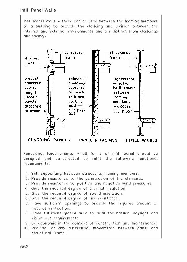
Infill Panel Walls ~ these can be used between the framing members
of a building to provide the cladding and division between the
internal and external environments and are distinct from claddings
and facing:-
Functional Requirements ~ all forms of infill panel should be
designed and constructed to fulfil the following functional
requirements:-
1. Self supporting between structural framing members.
2. Provide resistance to the penetration of the elements.
3. Provide resistance to positive and negative wind pressures.
4. Give the required degree of thermal insulation.
5. Give the required degree of sound insulation.
6. Give the required degree of fire resistance.
7. Have sufficient openings to provide the required amount of
natural ventilation.
8. Have sufficient glazed area to fulfil the natural daylight and
vision out requirements.
9. Be economic in the context of construction and maintenance.
10. Provide for any differential movements between panel and
structural frame.
552
Infill Panel Walls
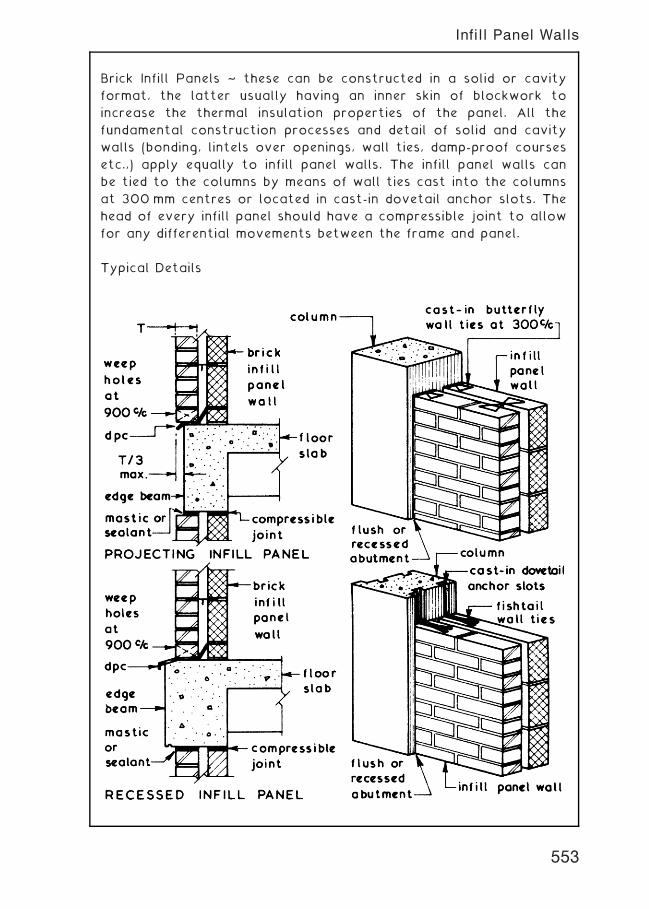
Brick Infill Panels ~ these can be constructed in a solid or cavity
format, the latter usually having an inner skin of blockwork to
increase the thermal insulation properties of the panel. All the
fundamental construction processes and detail of solid and cavity
walls (bonding, lintels over openings, wall ties, damp-proof courses
etc.,) apply equally to infill panel walls. The infill panel walls can
be tied to the columns by means of wall ties cast into the columns
at 300 mm centres or located in cast-in dovetail anchor slots. The
head of every infill panel should have a compressible joint to allow
for any differential movements between the frame and panel.
Typical Details
553
Infill Panel Walls
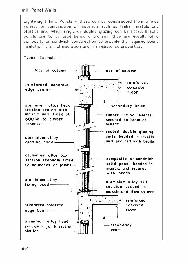
Lightweight Infill Panels ~ these can be constructed from a wide
variety or combination of materials such as timber, metals and
plastics into which single or double glazing can be fitted. If solid
panels are to be used below a transom they are usually of a
composite or sandwich construction to provide the required sound
insulation, thermal insulation and fire resistance properties.
554
Infill Panel Walls
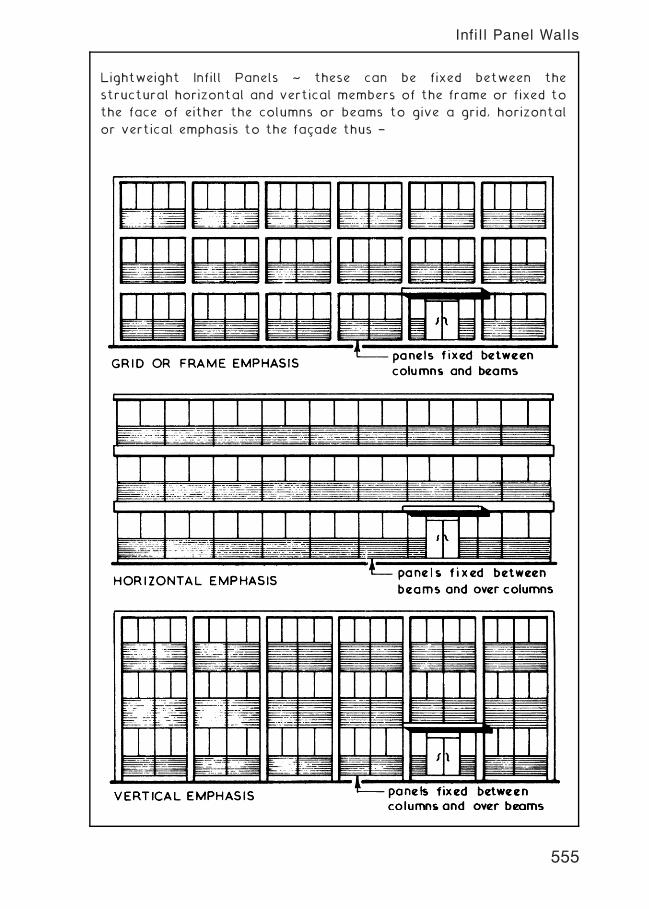
Lightweight Infill Panels ~ these can be fixed between the
structural horizontal and vertical members of the frame or fixed to
the face of either the columns or beams to give a grid, horizontal
or vertical emphasis to the facade thus †
555
Infill Panel Walls
Overcladding ~ a superficial treatment, applied either as a
component of new construction work, or as a facade and insulation
enhancement to existing structures. The outer weather resistant
decorative panelling is `loose fit' in concept, which is easily
replaced to suit changing tastes, new materials and company
image. Panels attach to the main structure with a grid of simple
metal framing or vertical timber battens. This allows space for a
ventilated and drained cavity, with provision for insulation to be
attached to the substructure; a normal requirement in upgrade/
refurbishment work.
Note (1): Cladding materials include, plastic laminates, fibre cement,
ceramics, aluminium, enamelled steel and various stone effects.
Note (2): Anti-bird mesh coated with intumescent material to form
a fire stop cavity barrier.
556
Rainscreen Cladding
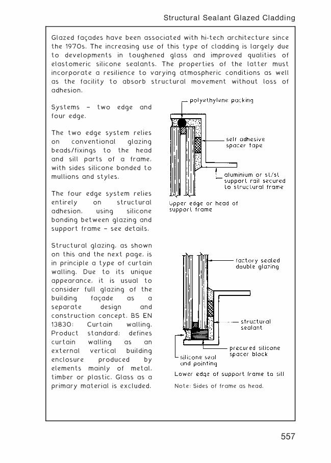
Glazed facades have been associated with hi-tech architecture since
the 1970s. The increasing use of this type of cladding is largely due
to developments in toughened glass and improved qualities of
elastomeric silicone sealants. The properties of the latter must
incorporate a resilience to varying atmospheric conditions as well
as the facility to absorb structural movement without loss of
adhesion.
Systems † two edge and
four edge.
The two edge system relies
on conventional glazing
beads/fixings to the head
and sill parts of a frame,
with sides silicone bonded to
mullions and styles.
The four edge system relies
entirely on structural
adhesion, using silicone
bonding between glazing and
support frame † see details.
Structural glazing, as shown
on this and the next page, is
in principle a type of curtain
walling. Due to its unique
appearance, it is usual to
consider full glazing of the
building facade as a
separate design and
construction concept. BS EN
13830: Curtain walling.
Product standard; defines
curtain walling as an
external vertical building
enclosure produced by
elements mainly of metal,
timber or plastic. Glass as a
primary material is excluded. Note: Sides of frame as head.
557
Structural Sealant Glazed Cladding
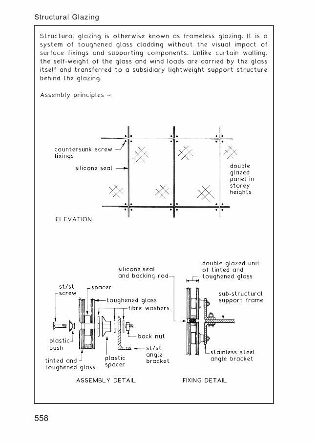
Structural glazing is otherwise known as frameless glazing. It is a
system of toughened glass cladding without the visual impact of
surface fixings and supporting components. Unlike curtain walling,
the self-weight of the glass and wind loads are carried by the glass
itself and transferred to a subsidiary lightweight support structure
behind the glazing.
Assembly principles ~
558
Structural Glazing
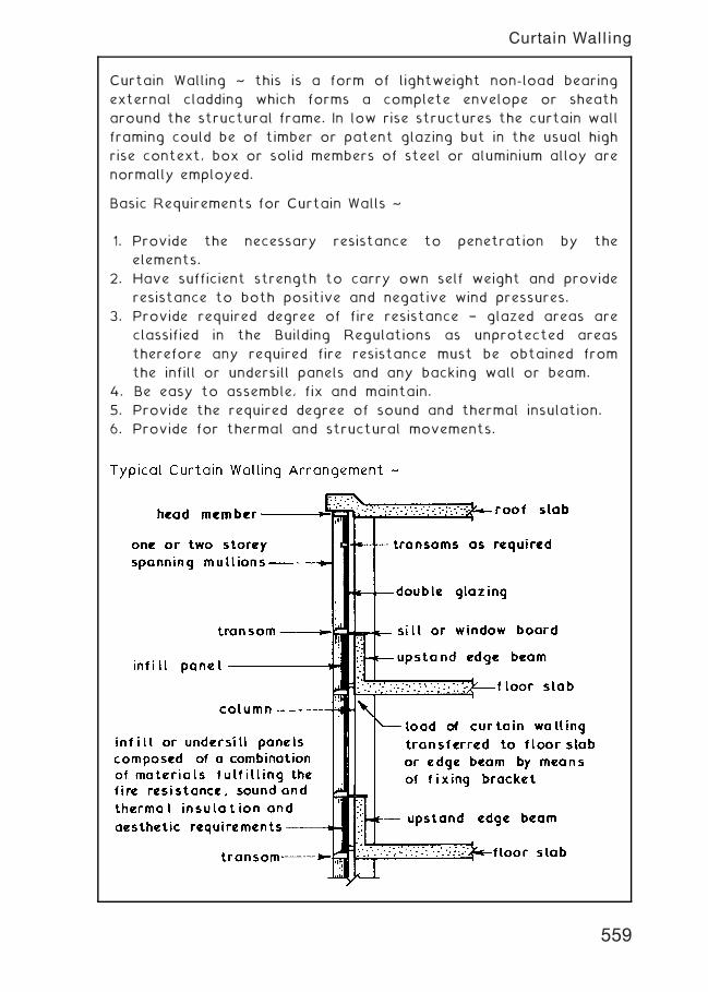
Curtain Walling ~ this is a form of lightweight non-load bearing
external cladding which forms a complete envelope or sheath
around the structural frame. In low rise structures the curtain wall
framing could be of timber or patent glazing but in the usual high
rise context, box or solid members of steel or aluminium alloy are
normally employed.
Basic Requirements for Curtain Walls ~
1. Provide the necessary resistance to penetration by the
elements.
2. Have sufficient strength to carry own self weight and provide
resistance to both positive and negative wind pressures.
3. Provide required degree of fire resistance † glazed areas are
classified in the Building Regulations as unprotected areas
therefore any required fire resistance must be obtained from
the infill or undersill panels and any backing wall or beam.
4. Be easy to assemble, fix and maintain.
5. Provide the required degree of sound and thermal insulation.
6. Provide for thermal and structural movements.
559
Curtain Walling
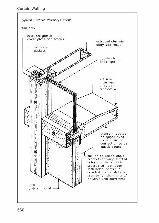
560
Curtain Walling
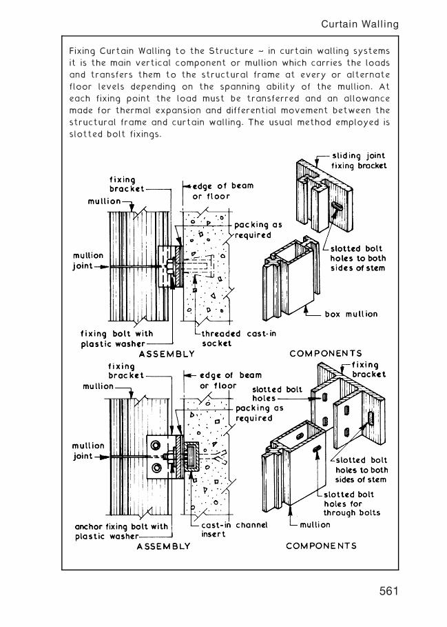
Fixing Curtain Walling to the Structure ~ in curtain walling systems
it is the main vertical component or mullion which carries the loads
and transfers them to the structural frame at every or alternate
floor levels depending on the spanning ability of the mullion. At
each fixing point the load must be transferred and an allowance
made for thermal expansion and differential movement between the
structural frame and curtain walling. The usual method employed is
slotted bolt fixings.
561
Curtain Walling
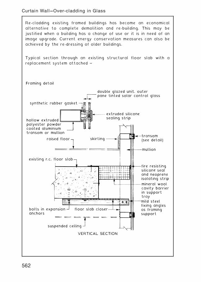
Re-cladding existing framed buildings has become an economical
alternative to complete demolition and re-building. This may be
justified when a building has a change of use or it is in need of an
image upgrade. Current energy conservation measures can also be
achieved by the re-dressing of older buildings.
Typical section through an existing structural floor slab with a
replacement system attached ~
562
Curtain Wall---Over-cladding in Glass
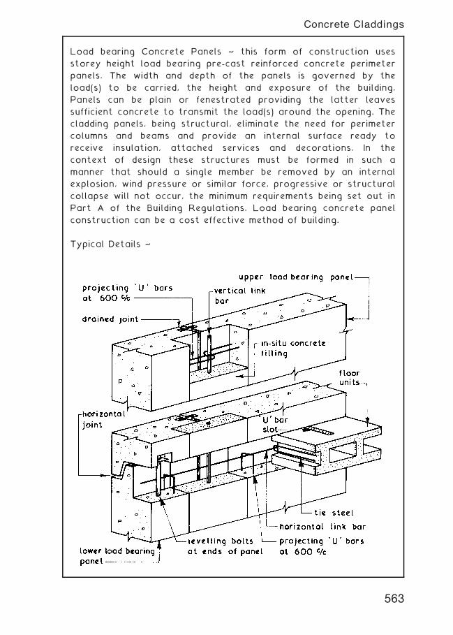
Load bearing Concrete Panels ~ this form of construction uses
storey height load bearing pre-cast reinforced concrete perimeter
panels. The width and depth of the panels is governed by the
load(s) to be carried, the height and exposure of the building.
Panels can be plain or fenestrated providing the latter leaves
sufficient concrete to transmit the load(s) around the opening. The
cladding panels, being structural, eliminate the need for perimeter
columns and beams and provide an internal surface ready to
receive insulation, attached services and decorations. In the
context of design these structures must be formed in such a
manner that should a single member be removed by an internal
explosion, wind pressure or similar force, progressive or structural
collapse will not occur, the minimum requirements being set out in
Part A of the Building Regulations. Load bearing concrete panel
construction can be a cost effective method of building.
Typical Details ~
563
Concrete Claddings
Concrete Cladding Panels ~ these are usually of reinforced precast
concrete to an undersill or storey height format, the former being
sometimes called apron panels. All precast concrete cladding
panels should be designed and installed to fulfil the following
functions:-
1. Self supporting between framing members.
2. Provide resistance to penetration by the natural elements.
3. Resist both positive and negative wind pressures.
4. Provide required degree of fire resistance.
5. Provide required degree of thermal insulation by having
the insulating material incorporated within the body of the
cladding or alternatively allow the cladding to act as the
outer leaf of cavity wall panel.
6. Provide required degree of sound insulation.
Undersill or Apron Cladding Panels ~ these are designed to span
from column to column and provide a seating for the windows
located above. Levelling is usually carried out by wedging and
packing from the lower edge before being fixed with grouted
dowels.
Typical Details ~
564
Concrete Claddings
Storey Height Cladding Panels ~ these are designed to span
vertically from beam to beam and can be fenestrated if required.
Levelling is usually carried out by wedging and packing from floor
level before being fixed by bolts or grouted dowels.
Typical Details ~
565
Concrete Claddings
Concrete Surface Finishes ~ it is not easy to produce a concrete
surface with a smooth finish of uniform colour direct from the
mould or formwork since the colour of the concrete can be
affected by the cement and fine aggregate used. The concrete
surface texture can be affected by the aggregate grading, cement
content, water content, degree of compaction, pin holes caused by
entrapped air and rough patches caused by adhesion to parts of
the formworks. Complete control over the above mentioned causes
is difficult under ideal factory conditions and almost impossible
under normal site conditions. The use of textured and applied
finishes has therefore the primary function of improving the
appearance of the concrete surface and in some cases it will help
to restrict the amount of water which reaches a vertical joint.
Casting ~ concrete components can usually be cast in-situ or
precast in moulds. Obtaining a surface finish to concrete cast in-
situ is usually carried out against a vertical face, whereas precast
concrete components can be cast horizontally and treated on
either upper or lower mould face. Apart from a plain surface
concrete the other main options are:-
1. Textured and profiled surfaces.
2. Tooled finishes.
3. Cast-on finishes. (see next page)
4. Exposed aggregate finishes. (see next page)
Textured and Profiled Surfaces ~ these can be produced on the
upper surface of a horizontal casting by rolling, tamping, brushing
and sawing techniques but variations in colour are difficult to
avoid. Textured and profiled surfaces can be produced on the lower
face of a horizontal casting by using suitable mould linings.
Tooled Finishes ~ the surface of hardened concrete can be tooled
by bush hammering, point tooling and grinding. Bush hammering and
point tooling can be carried out by using an electric or pneumatic
hammer on concrete which is at least three weeks old provided
gravel aggregates have not been used since these tend to shatter
leaving surface pits. Tooling up to the arris could cause spalling
therefore a 10 mm wide edge margin should be left untooled.
Grinding the hardened concrete consists of smoothing the surface
with a rotary carborundum disc which may have an integral water
feed. Grinding is a suitable treatment for concrete containing the
softer aggregates such as limestone.
566
Concrete Surface Finishes
Cast-on Finishes ~ these finishes include split blocks, bricks, stone,
tiles and mosaic. Cast-on finishes to the upper surface of a
horizontal casting are not recommended although such finishes
could be bedded onto the fresh concrete. Lower face treatment is
by laying the materials with sealed or grouted joints onto the base
of mould or alternatively the materials to be cast-on may be
located in a sand bed spread over the base of the mould.
Exposed Aggregate Finishes ~ attractive effects can be obtained by
removing the skin of hardened cement paste or surface matrix,
which forms on the surface of concrete, to expose the aggregate.
The methods which can be employed differ with the casting position.
Horizontal Casting † treatment to the upper face can consist of
spraying with water and brushing some two hours after casting,
trowelling aggregate into the fresh concrete surface or by using
the felt-float method. This method consists of trowelling 10 mm of
dry mix fine concrete onto the fresh concrete surface and using
the felt pad to pick up the cement and fine particles from the
surface leaving a clean exposed aggregate finish.
Treatment to the lower face can consist of applying a retarder to
the base of the mould so that the partially set surface matrix can
be removed by water and/or brushing as soon as the castings are
removed from the moulds. When special face aggregates are used
the sand bed method could be employed.
Vertical Casting † exposed aggregate finishes to the vertical faces
can be obtained by tooling the hardened concrete or they can be
cast-on by the aggregate transfer process. This consists of
sticking the selected aggregate onto the rough side of pegboard
sheets with a mixture of water soluble cellulose compounds and
sand fillers. The cream like mixture is spread evenly over the
surface of the pegboard to a depth of one third the aggregate size
and the aggregate sprinkled or placed evenly over the surface
before being lightly tamped into the adhesive. The prepared board
is then set aside for 36 hours to
set before being used as a liner
to the formwork or mould. The
liner is used in conjunction with a
loose plywood or hardboard
baffle placed against the face of
the aggregate. The baffle board
is removed as the concrete is
being placed.
567
Concrete Surface Finishes
Discolouration ~ manifests as a patchy surface finish. It is caused
where there are differences in hydration or moisture loss during the
concrete set, due to concentrations of cement or where
aggregates become segregated. Both of these will produce
moisture content differences at the surface. Areas with a darker
surface indicate the greater loss of moisture, possibly caused by
insufficient mixing and/or poorly sealed formwork producing
differences in surface absorption.
Crazing ~ surface shrinkage cracks caused by a cement rich surface
skin or by too much water in the mix. Out-of-date cement can have
the same effect as well as impairing the strength of the concrete.
Lime bloom ~ a chalky surface deposit produced when the calcium
present in cement reacts to contamination from moisture in the
atmosphere or rainwater during the hydration process. Generally
resolved by dry brushing or with a 20:1 water/hydrochloric acid
wash.
Scabbing ~ small areas or surface patches of concrete falling away
as the formwork is struck. Caused by poor preparation of
formwork, ie. insufficient use of mould oil or by formwork having a
surface texture that is too rough.
Blow holes ~ otherwise known as surface popping. Possible causes
are use of formwork finishes with nil or low absorbency or by
insufficient vibration of concrete during placement.
Rust staining ~ if not caused by inadequate concrete cover to
reinforcement, this characteristic is quite common where iron rich
aggregates or pyrites are used. Rust-brown stains are a feature
and there may also be some cracking where the iron reacts with
the cement.
Dusting ~ caused by unnaturally rapid hardening of concrete and
possibly where out-of-date cement is used. The surface of set
concrete is dusty and friable.
568
Concrete -- Surface Defects
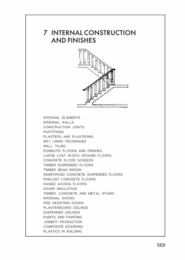
7 INTERNAL CONSTRUCTIONAND FINISHES
INTERNAL ELEMENTS
INTERNAL WALLS
CONSTRUCTION JOINTS
PARTITIONS
PLASTERS AND PLASTERING
DRY LINING TECHNIQUES
WALL TILING
DOMESTIC FLOORS AND FINISHES
LARGE CAST IN-SITU GROUND FLOORS
CONCRETE FLOOR SCREEDS
TIMBER SUSPENDED FLOORS
TIMBER BEAM DESIGN
REINFORCED CONCRETE SUSPENDED FLOORS
PRECAST CONCRETE FLOORS
RAISED ACCESS FLOORS
SOUND INSULATION
TIMBER, CONCRETE AND METAL STAIRS
INTERNAL DOORS
FIRE RESISTING DOORS
PLASTERBOARD CEILINGS
SUSPENDED CEILINGS
PAINTS AND PAINTING
JOINERY PRODUCTION
COMPOSITE BOARDING
PLASTICS IN BUILDING
569
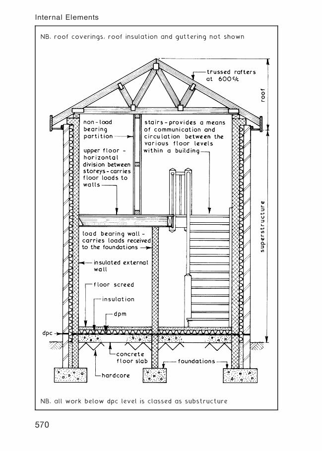
NB. roof coverings, roof insulation and guttering not shown
NB. all work below dpc level is classed as substructure
570
Internal Elements
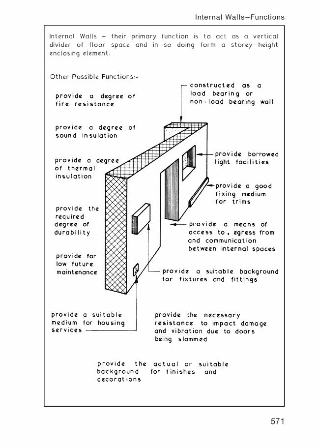
Internal Walls ~ their primary function is to act as a vertical
divider of floor space and in so doing form a storey height
enclosing element.
571
Internal Walls---Functions
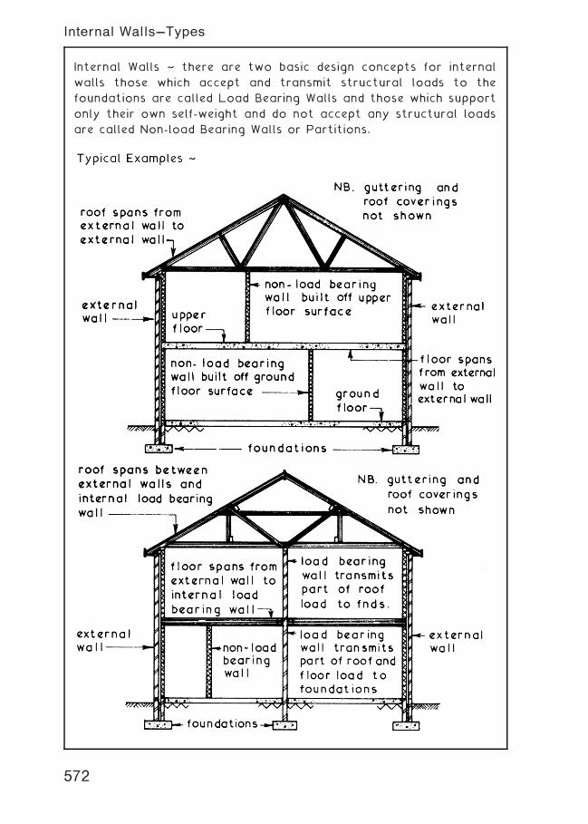
Internal Walls ~ there are two basic design concepts for internal
walls those which accept and transmit structural loads to the
foundations are called Load Bearing Walls and those which support
only their own self-weight and do not accept any structural loads
are called Non-load Bearing Walls or Partitions.
572
Internal Walls---Types
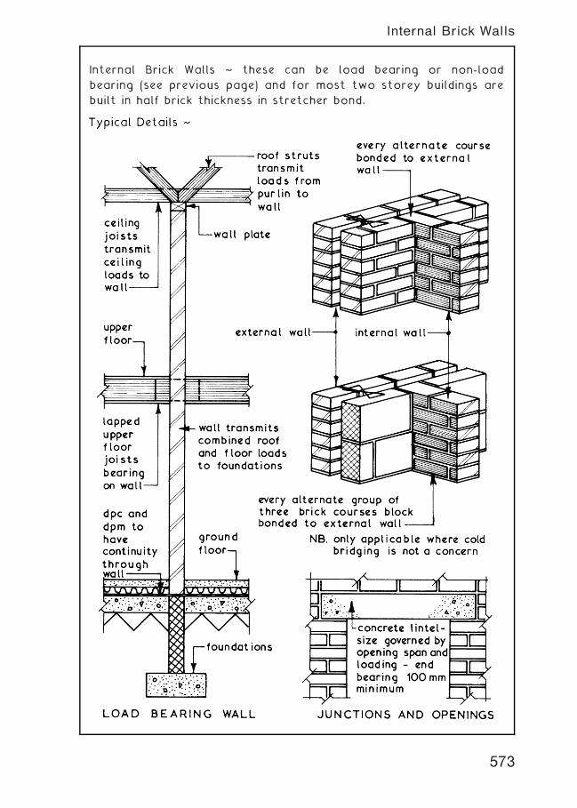
Internal Brick Walls ~ these can be load bearing or non-load
bearing (see previous page) and for most two storey buildings are
built in half brick thickness in stretcher bond.
573
Internal Brick Walls
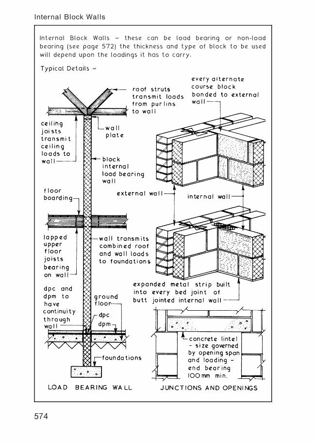
Internal Block Walls ~ these can be load bearing or non-load
bearing (see page 572) the thickness and type of block to be used
will depend upon the loadings it has to carry.
574
Internal Block Walls
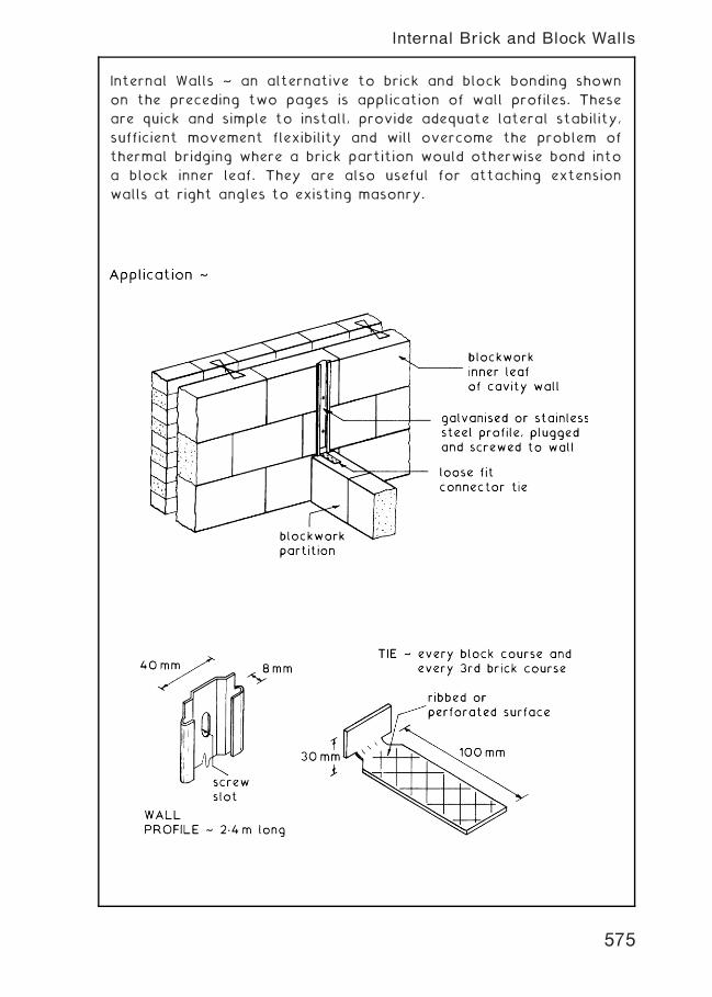
Internal Walls ~ an alternative to brick and block bonding shown
on the preceding two pages is application of wall profiles. These
are quick and simple to install, provide adequate lateral stability,
sufficient movement flexibility and will overcome the problem of
thermal bridging where a brick partition would otherwise bond into
a block inner leaf. They are also useful for attaching extension
walls at right angles to existing masonry.
575
Internal Brick and Block Walls
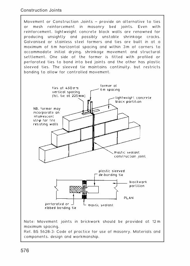
Movement or Construction Joints ~ provide an alternative to ties
or mesh reinforcement in masonry bed joints. Even with
reinforcement, lightweight concrete block walls are renowned for
producing unsightly and possibly unstable shrinkage cracks.
Galvanised or stainless steel formers and ties are built in at a
maximum of 6m horizontal spacing and within 3m of corners to
accommodate initial drying, shrinkage movement and structural
settlement. One side of the former is fitted with profiled or
perforated ties to bond into bed joints and the other has plastic
sleeved ties. The sleeved tie maintains continuity, but restricts
bonding to allow for controlled movement.
Note: Movement joints in brickwork should be provided at 12 m
maximum spacing.
Ref. BS 5628-3: Code of practice for use of masonry. Materials and
components, design and workmanship.
576
Construction Joints
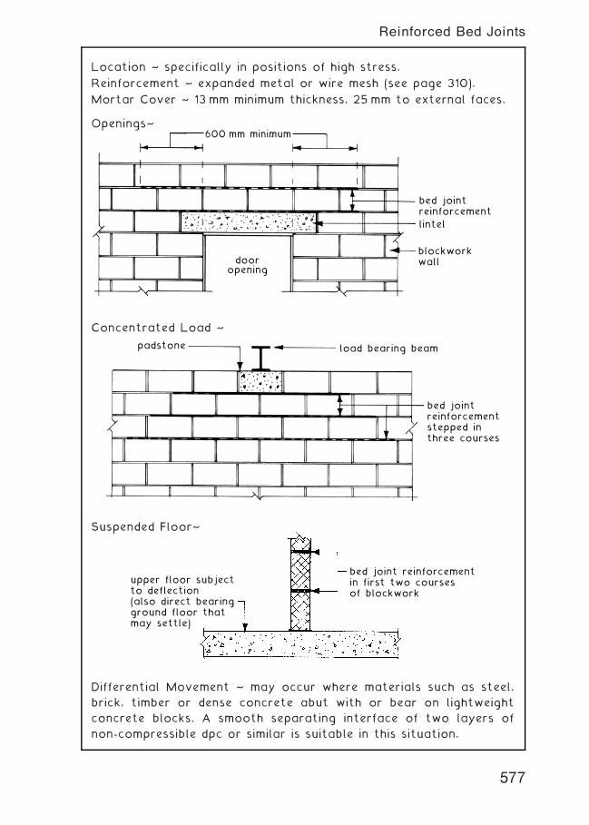
Location ~ specifically in positions of high stress.
Reinforcement ~ expanded metal or wire mesh (see page 310).
Mortar Cover ~ 13 mm minimum thickness, 25 mm to external faces.
Openings~600 mm minimum
dooropening
blockworkwall
bed jointreinforcement
lintel
Concentrated Load ~
padstone load bearing beam
bed jointreinforcementstepped inthree courses
Suspended Floor~
bed joint reinforcementin first two coursesof blockwork
upper floor subjectto deflection(also direct bearingground floor thatmay settle)
Differential Movement ~ may occur where materials such as steel,
brick, timber or dense concrete abut with or bear on lightweight
concrete blocks. A smooth separating interface of two layers of
non-compressible dpc or similar is suitable in this situation.
577
Reinforced Bed Joints
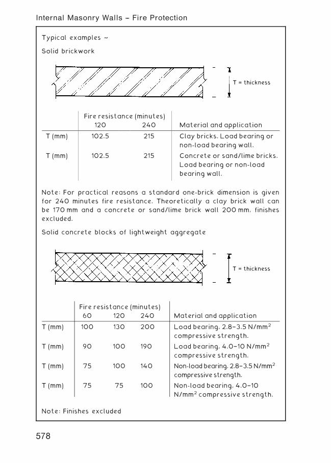
Typical examples ~
Solid brickwork
T = thickness
Note: For practical reasons a standard one-brick dimension is given
for 240 minutes fire resistance. Theoretically a clay brick wall can
be 170 mm and a concrete or sand/lime brick wall 200 mm, finishes
excluded.
Solid concrete blocks of lightweight aggregate
T = thickness
Note: Finishes excluded
Fire resistance (minutes)
120 240 Material and application
T (mm) 102.5 215 Clay bricks. Load bearing or
non-load bearing wall.
T (mm) 102.5 215 Concrete or sand/lime bricks.
Load bearing or non-load
bearing wall.
Fire resistance (minutes)
60 120 240 Material and application
T (mm) 100 130 200 Load bearing, 2.8†3.5 N/mm2
compressive strength.
T (mm) 90 100 190 Load bearing, 4.0†10 N/mm2
compressive strength.
T (mm) 75 100 140 Non-loadbearing,2.8†3.5N/mm2
compressivestrength.
T (mm) 75 75 100 Non-load bearing, 4.0†10
N/mm2 compressive strength.
578
Internal Masonry Walls -- Fire Protection
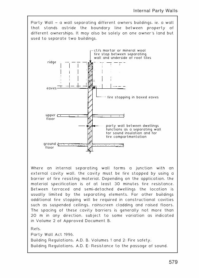
Party Wall ~ a wall separating different owners buildings, ie. a wall
that stands astride the boundary line between property of
different ownerships. It may also be solely on one owner's land but
used to separate two buildings.
ridge
eaves
upperfloor
groundfloor
party wall between dwellingsfunctions as a separating wallfor sound insulation and forfire compartmentation
fire stopping in boxed eaves
ct/s mortar or mineral woolfire stop between separatingwall and underside of roof tiles
Where an internal separating wall forms a junction with an
external cavity wall, the cavity must be fire stopped by using a
barrier of fire resisting material. Depending on the application, the
material specification is of at least 30 minutes fire resistance.
Between terraced and semi-detached dwellings the location is
usually limited by the separating elements. For other buildings
additional fire stopping will be required in constructional cavities
such as suspended ceilings, rainscreen cladding and raised floors.
The spacing of these cavity barriers is generally not more than
20 m in any direction, subject to some variation as indicated
in Volume 2 of Approved Document B.
Refs.
Party Wall Act 1996.
Building Regulations, A.D. B, Volumes 1 and 2: Fire safety.
Building Regulations, A.D. E: Resistance to the passage of sound.
579
Internal Party Walls
Requirements for fire and sound resisting construction ~
Typical masonry construction~
cavity stopped with a non-combustiblemineral wool closer unless cavityis fully filled with mineral wool insulation
external cavity wall
Planview solid or cavity construction
of separating wall
vertical dpc
Typical timber framed construction~
one layer 12.5 mm plasterboardlining, two layers where thereis a separating floor
external cavity wall
Planview cavity construction
separating wall
insulation
vertical dpc cavity fire stopped as above
580
Internal Party/Separating Walls
Internal Partitions ~ these are vertical dividers which are used to
separate the internal space of a building into rooms and
circulation areas such as corridors. Partitions which give support
to a floor or roof are classified as load bearing whereas those
which give no such support are called non-load bearing.
Load Bearing Partitions ~ these walls can be constructed of bricks,
blocks or in-situ concrete by traditional methods and have the
design advantages of being capable of having good fire resistance
and/or high sound insulation. Their main disadvantage is
permanence giving rise to an inflexible internal layout.
Non-load Bearing Partitions ~ the wide variety of methods
available makes it difficult to classify the form of partition but
most can be placed into one of three groups:-
1. Masonry partitions.
2. Stud partitions † see pages 582 & 583.
3. Demountable partitions † see pages 585 & 586.
Masonry Partitions ~ these are usually built with blocks of clay or
lightweight concrete which are readily available and easy to
construct thus making them popular. These masonry partitions
should be adequately tied to the structure or load bearing walls to
provide continuity as a sound barrier, provide edge restraint and
to reduce the shrinkage cracking which inevitably occurs at
abutments. Wherever possible openings for doors should be in the
form of storey height frames to provide extra stiffness at these
positions.
581
Partitions
Timber Stud Partitions ~ these are non-load bearing internal
dividing walls which are easy to construct, lightweight, adaptable
and can be clad and infilled with various materials to give different
finishes and properties. The timber studs should be of prepared or
planed material to ensure that the wall is of constant thickness
with parallel faces. Stud spacings will be governed by the size and
spanning ability of the facing or cladding material.
582
Timber Stud Partitions
Stud Partitions ~ these non-load bearing partitions consist of a
framework of vertical studs to which the facing material can be
attached. The void between the studs created by the two faces
can be infilled to meet specific design needs. The traditional
material for stud partitions is timber (see Timber Stud Partitions
on previous page) but a similar arrangement can be constructed
using metal studs faced on both sides with plasterboard.
583
Metal Stud Partitions
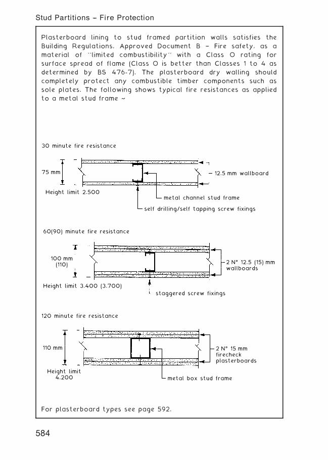
Plasterboard lining to stud framed partition walls satisfies the
Building Regulations, Approved Document B † Fire safety, as a
material of ``limited combustibility'' with a Class O rating for
surface spread of flame (Class O is better than Classes 1 to 4 as
determined by BS 476-7). The plasterboard dry walling should
completely protect any combustible timber components such as
sole plates. The following shows typical fire resistances as applied
to a metal stud frame ~
30 minute fire resistance
75 mm
Height limit 2.500
self drilling/self tapping screw fixings
metal channel stud frame
12.5 mm wallboard
staggered screw fixings
2 Nƒ 12.5 (15) mmwallboards
60(90) minute fire resistance
100 mm(110)
Height limit 3.400 (3.700)
110 mm
120 minute fire resistance
Height limit4.200 metal box stud frame
2 Nƒ 15 mmfirecheckplasterboards
For plasterboard types see page 592.
584
Stud Partitions -- Fire Protection
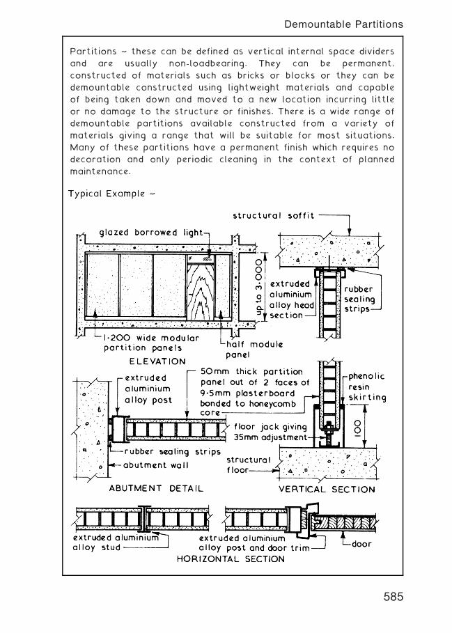
Partitions ~ these can be defined as vertical internal space dividers
and are usually non-loadbearing. They can be permanent,
constructed of materials such as bricks or blocks or they can be
demountable constructed using lightweight materials and capable
of being taken down and moved to a new location incurring little
or no damage to the structure or finishes. There is a wide range of
demountable partitions available constructed from a variety of
materials giving a range that will be suitable for most situations.
Many of these partitions have a permanent finish which requires no
decoration and only periodic cleaning in the context of planned
maintenance.
585
Demountable Partitions
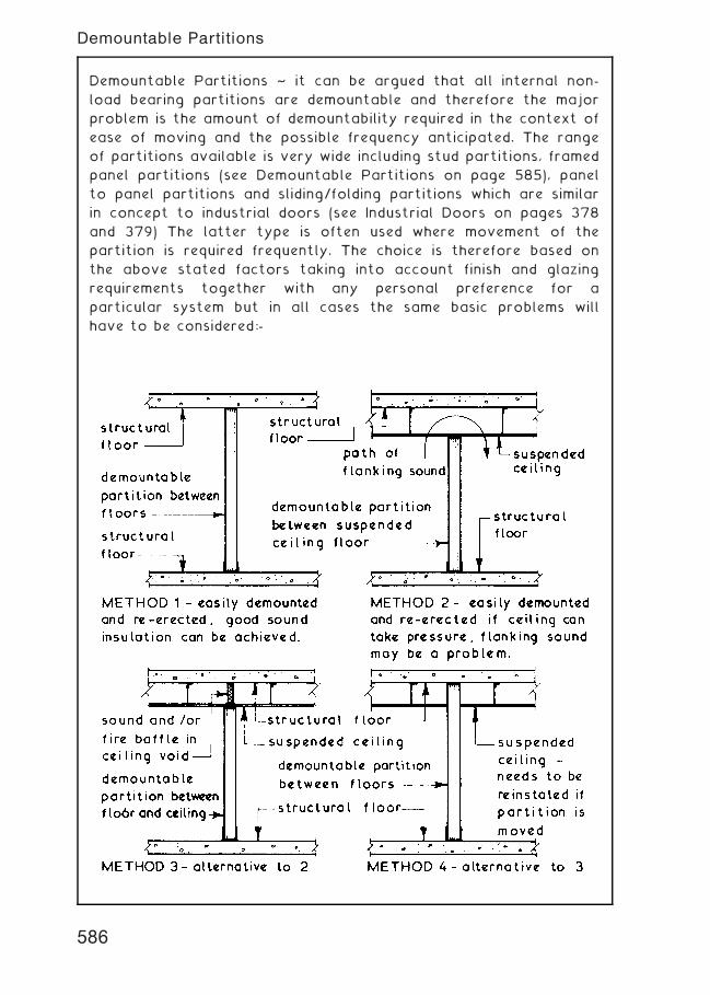
Demountable Partitions ~ it can be argued that all internal non-
load bearing partitions are demountable and therefore the major
problem is the amount of demountability required in the context of
ease of moving and the possible frequency anticipated. The range
of partitions available is very wide including stud partitions, framed
panel partitions (see Demountable Partitions on page 585), panel
to panel partitions and sliding/folding partitions which are similar
in concept to industrial doors (see Industrial Doors on pages 378
and 379) The latter type is often used where movement of the
partition is required frequently. The choice is therefore based on
the above stated factors taking into account finish and glazing
requirements together with any personal preference for a
particular system but in all cases the same basic problems will
have to be considered:-
586
Demountable Partitions
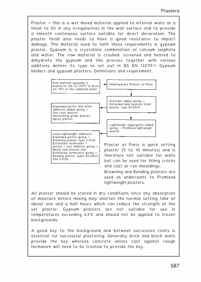
Plaster ~ this is a wet mixed material applied to internal walls as a
finish to fill in any irregularities in the wall surface and to provide
a smooth continuous surface suitable for direct decoration. The
plaster finish also needs to have a good resistance to impact
damage. The material used to fulfil these requirements is gypsum
plaster. Gypsum is a crystalline combination of calcium sulphate
and water. The raw material is crushed, screened and heated to
dehydrate the gypsum and this process together with various
additives defines its type as set out in BS EN 13279-1: Gypsum
binders and gypsum plasters. Definitions and requirement.
Raw material (gypsum) isheated to 150 to 170ƒC to driveoff 75% of the combined water
Expanded perlite and otheradditives added giving …One coat plaster;Renovating grade plaster;Spray plaster.
Usual lightweight additives:-Expanded perlite giving …Browning plaster type C3/20.Exfoliated vermiculite + perlite + rust inhibitor giving …Metal lath plaster andExfoliated vermiculite giving …Bonding plaster types B4/20/2and C3/20.
Retarder added giving …Retarded hemi hydrate finishplaster type B1/20/2
Lightweight aggregates addedgiving … Premixed lightweightplaster
Hemi-hydrate Plaster of Paris
Plaster of Paris is quick setting
plaster (5 to 10 minutes) and is
therefore not suitable for walls
but can be used for filling cracks
and cast or run mouldings.
Browning and Bonding plasters are
used as undercoats to Premixed
lightweight plasters.
All plaster should be stored in dry conditions since any absorption
of moisture before mixing may shorten the normal setting time of
about one and a half hours which can reduce the strength of the
set plaster. Gypsum plasters are not suitable for use in
temperatures exceeding 43�C and should not be applied to frozen
backgrounds.
A good key to the background and between successive coats is
essential for successful plastering. Generally brick and block walls
provide the key whereas concrete unless cast against rough
formwork will need to be treated to provide the key.
587
Plasters
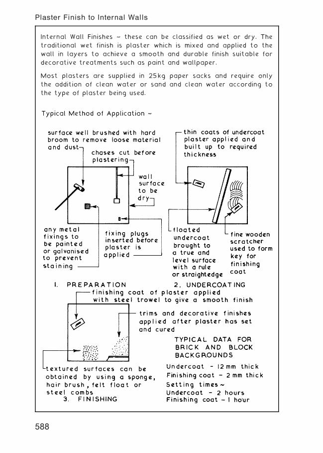
Internal Wall Finishes ~ these can be classified as wet or dry. The
traditional wet finish is plaster which is mixed and applied to the
wall in layers to achieve a smooth and durable finish suitable for
decorative treatments such as paint and wallpaper.
Most plasters are supplied in 25kg paper sacks and require only
the addition of clean water or sand and clean water according to
the type of plaster being used.
588
Plaster Finish to Internal Walls

Plasterboard ~ a board material made of two sheets of thin mill †
board with gypsum plaster between † three edge profiles are
available:-
Tapered Edge †
A flush seamless surface is obtained by filling the joint with a
special filling plaster, applying a joint tape over the filling and
finishing with a thin layer of joint filling plaster the edge of which
is feathered out using a slightly damp jointing sponge.
Square Edge † edges are close butted and finished with a cover
fillet or the joint is covered with a jute scrim before being
plastered.
Bevelled Edge † edges are close butted forming a vee-joint which
becomes a feature of the lining.
589
Dry Lining Techniques
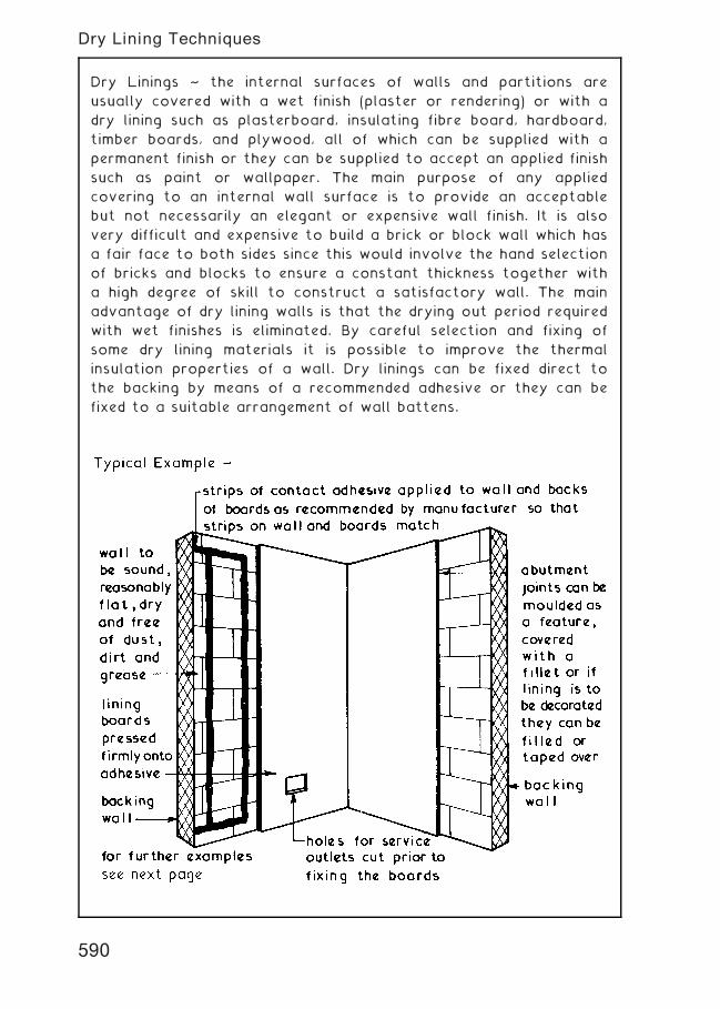
Dry Linings ~ the internal surfaces of walls and partitions are
usually covered with a wet finish (plaster or rendering) or with a
dry lining such as plasterboard, insulating fibre board, hardboard,
timber boards, and plywood, all of which can be supplied with a
permanent finish or they can be supplied to accept an applied finish
such as paint or wallpaper. The main purpose of any applied
covering to an internal wall surface is to provide an acceptable
but not necessarily an elegant or expensive wall finish. It is also
very difficult and expensive to build a brick or block wall which has
a fair face to both sides since this would involve the hand selection
of bricks and blocks to ensure a constant thickness together with
a high degree of skill to construct a satisfactory wall. The main
advantage of dry lining walls is that the drying out period required
with wet finishes is eliminated. By careful selection and fixing of
some dry lining materials it is possible to improve the thermal
insulation properties of a wall. Dry linings can be fixed direct to
the backing by means of a recommended adhesive or they can be
fixed to a suitable arrangement of wall battens.
590
Dry Lining Techniques
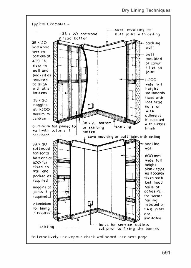
591
Dry Lining Techniques
Plasterboard Types ~ to BS EN 520: Gypsum plasterboards.
Definitions, requirements and test methods.
BS PLASTERBOARDS:~
1. Wallboard † ivory faced for taping, jointing and direct
decoration; grey faced for finishing plaster or wall adhesion
with dabs. General applications, i.e. internal walls, ceilings and
partitions. Thicknesses: 9„5, 12„5 and 15 mm. Widths: 900 and
1200mm. Lengths: vary between 1800 and 3000 mm.
2. Baseboard † lining ceilings requiring direct plastering.
Thickness: 9„5 mm. Width: 900 mm. Length: 1220 mm and,
Thickness: 12„5 mm. Width: 600 mm. Length: 1220 mm.
3. Moisture Resistant † wallboard for bathrooms and kitchens.
Pale green colour, ideal base for ceramic tiling.
Thicknesses: 12„5 mm and 15 mm. Width: 1200 mm.
Lengths: 2400, 2700 and 3000 mm.
4. Firecheck † wallboard of glass fibre reinforced vermiculite and
gypsum for fire cladding.
Thicknesses: 12„5 and 15 mm. Widths: 900 and 1200mm.
Lengths: 1800, 2400, 2700 and 3000 mm.
A25 mmthickness is also produced, 600mmwide � 3000 mm long.
5. Lath † rounded edge wallboard of limited area for easy
application to ceilings requiring a direct plaster finish.
Thicknesses: 9„5 and 12„5 mm. Widths: 400 and 600 mm.
Lengths: 1200 and 1220 mm.
6. Plank † used as fire protection for structural steel and timber, in
addition to sound insulation in wall panels and floating floors.
Thickness: 19 mm. Width: 600 mm.
Lengths: 2350, 2400, 2700 and 3000 mm.
NON † STANDARD PLASTERBOARDS:~
1. Contour † only 6 mm in thickness to adapt to curved
featurework. Width: 1200 mm. Lengths: 2400m and 3000 mm.
2. Vapourcheck † a metallized polyester wallboard lining to
provide an integral water vapour control layer.
Thicknesses: 9„5 and 12„5 mm. Widths: 900 and 1200mm.
Lengths: vary between 1800 and 3000 mm.
3. Thermalcheck † various expanded or foamed insulants are
bonded to wallboard. Approximately 25†50 mm overall thickness
in board sizes 1200 � 2400mm.
592
Plasterboard
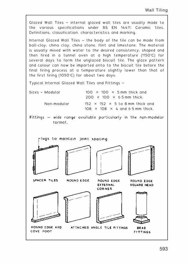
Glazed Wall Tiles ~ internal glazed wall tiles are usually made to
the various specifications under BS EN 14411: Ceramic tiles.
Definitions, classification, characteristics and marking.
Internal Glazed Wall Tiles ~ the body of the tile can be made from
ball-clay, china clay, china stone, flint and limestone. The material
is usually mixed with water to the desired consistency, shaped and
then fired in a tunnel oven at a high temperature (1150�C) for
several days to form the unglazed biscuit tile. The glaze pattern
and colour can now be imparted onto to the biscuit tile before the
final firing process at a temperature slightly lower than that of
the first firing (1050�C) for about two days.
Typical Internal Glazed Wall Tiles and Fittings ~
Sizes † Modular 100 � 100 � 5 mm thick and
200 � 100 � 6„5 mm thick.
Non-modular 152 � 152 � 5 to 8 mm thick and
108 � 108 � 4 and 6„5 mm thick.
593
Wall Tiling
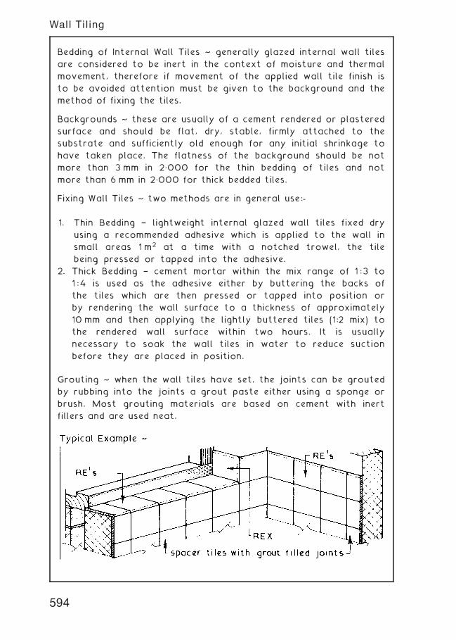
Bedding of Internal Wall Tiles ~ generally glazed internal wall tiles
are considered to be inert in the context of moisture and thermal
movement, therefore if movement of the applied wall tile finish is
to be avoided attention must be given to the background and the
method of fixing the tiles.
Backgrounds ~ these are usually of a cement rendered or plastered
surface and should be flat, dry, stable, firmly attached to the
substrate and sufficiently old enough for any initial shrinkage to
have taken place. The flatness of the background should be not
more than 3 mm in 2„000 for the thin bedding of tiles and not
more than 6 mm in 2„000 for thick bedded tiles.
Fixing Wall Tiles ~ two methods are in general use:-
1. Thin Bedding † lightweight internal glazed wall tiles fixed dry
using a recommended adhesive which is applied to the wall in
small areas 1 m2 at a time with a notched trowel, the tile
being pressed or tapped into the adhesive.
2. Thick Bedding † cement mortar within the mix range of 1 :3 to
1 :4 is used as the adhesive either by buttering the backs of
the tiles which are then pressed or tapped into position or
by rendering the wall surface to a thickness of approximately
10 mm and then applying the lightly buttered tiles (1:2 mix) to
the rendered wall surface within two hours. It is usually
necessary to soak the wall tiles in water to reduce suction
before they are placed in position.
Grouting ~ when the wall tiles have set, the joints can be grouted
by rubbing into the joints a grout paste either using a sponge or
brush. Most grouting materials are based on cement with inert
fillers and are used neat.
594
Wall Tiling
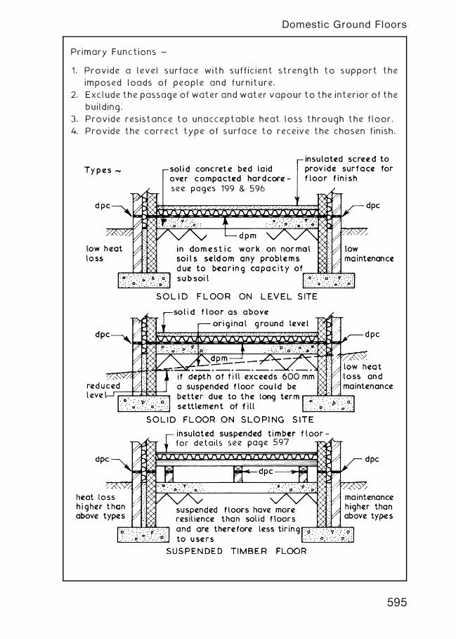
Primary Functions ~
1. Provide a level surface with sufficient strength to support the
imposed loads of people and furniture.
2. Exclude the passage of water andwater vapour to the interior of the
building.
3. Provide resistance to unacceptable heat loss through the floor.
4. Provide the correct type of surface to receive the chosen finish.
595
Domestic Ground Floors
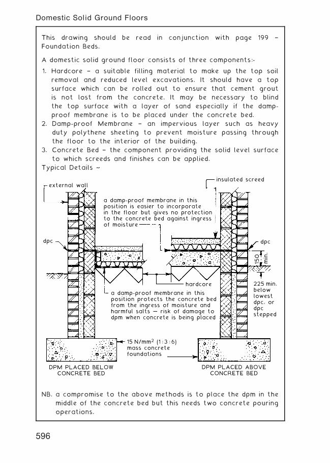
This drawing should be read in conjunction with page 199 †
Foundation Beds.
A domestic solid ground floor consists of three components:-
1. Hardcore † a suitable filling material to make up the top soil
removal and reduced level excavations. It should have a top
surface which can be rolled out to ensure that cement grout
is not lost from the concrete. It may be necessary to blind
the top surface with a layer of sand especially if the damp-
proof membrane is to be placed under the concrete bed.
2. Damp-proof Membrane † an impervious layer such as heavy
duty polythene sheeting to prevent moisture passing through
the floor to the interior of the building.
3. Concrete Bed † the component providing the solid level surface
to which screeds and finishes can be applied.
Typical Details ~
external wallinsulated screed
a damp-proof membrane in thisposition is easier to incorporatein the floor but gives no protectionto the concrete bed against ingressof moisture
a damp-proof membrane in thisposition protects the concrete bedfrom the ingress of moisture andharmful salts … risk of damage todpm when concrete is being placed
dpc dpc
225 min.belowlowestdpc, ordpcstepped
hardcore
DPM PLACED BELOWCONCRETE BED
DPM PLACED ABOVECONCRETE BED
15 N/mm2 (1 : 3 : 6)mass concretefoundations
150
min.
NB. a compromise to the above methods is to place the dpm in the
middle of the concrete bed but this needs two concrete pouring
operations.
596
Domestic Solid Ground Floors
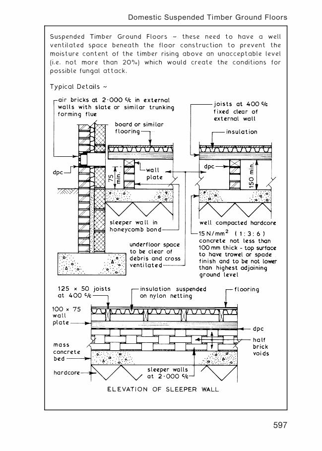
Suspended Timber Ground Floors ~ these need to have a well
ventilated space beneath the floor construction to prevent the
moisture content of the timber rising above an unacceptable level
(i.e. not more than 20%) which would create the conditions for
possible fungal attack.
597
Domestic Suspended Timber Ground Floors
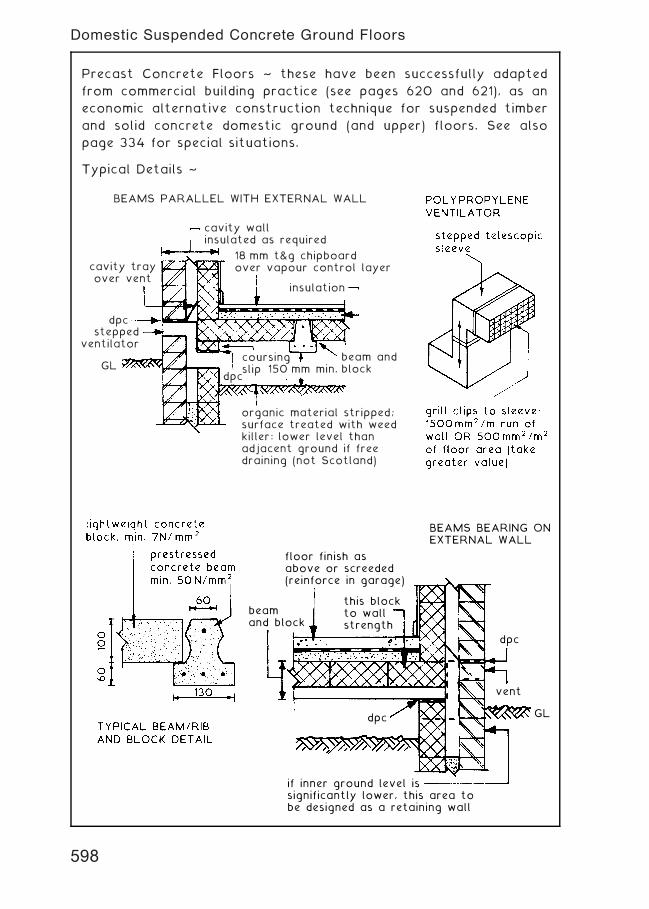
Precast Concrete Floors ~ these have been successfully adapted
from commercial building practice (see pages 620 and 621), as an
economic alternative construction technique for suspended timber
and solid concrete domestic ground (and upper) floors. See also
page 334 for special situations.
Typical Details ~
cavity wallinsulated as required
BEAMS PARALLEL WITH EXTERNAL WALL
18 mm t&g chipboardover vapour control layer
insulation
150 mm min.
organic material stripped;surface treated with weedkiller: lower level thanadjacent ground if freedraining (not Scotland)
GL
dpcstepped
ventilatorbeam andblock
coursingslip
dpc
cavity trayover vent
floor finish asabove or screeded(reinforce in garage)
BEAMS BEARING ONEXTERNAL WALL
this blockto wallstrength
beamand block
dpc
if inner ground level issignificantly lower, this area tobe designed as a retaining wall
GL
vent
dpc
598
Domestic Suspended Concrete Ground Floors
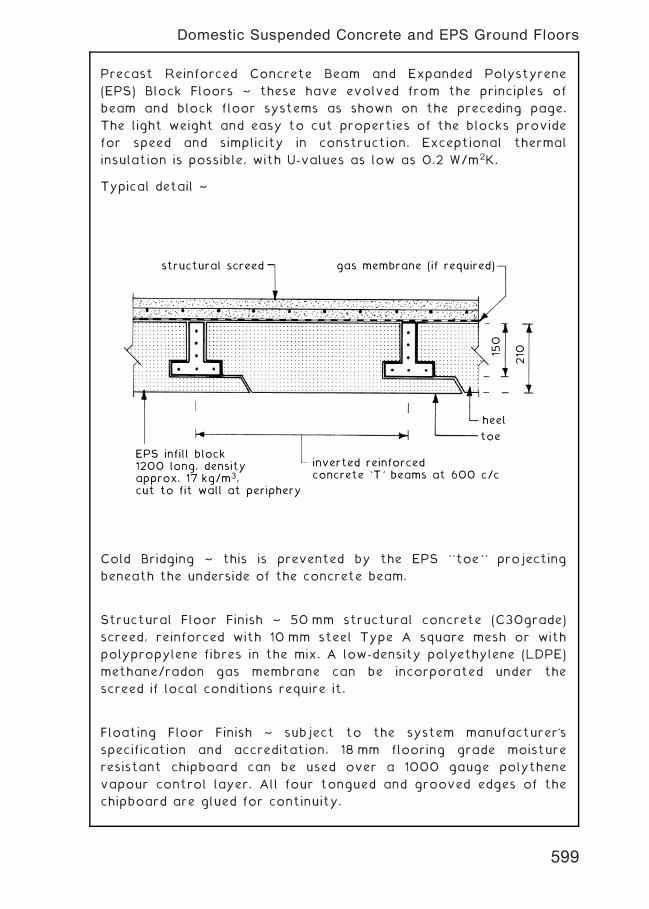
Precast Reinforced Concrete Beam and Expanded Polystyrene
(EPS) Block Floors ~ these have evolved from the principles of
beam and block floor systems as shown on the preceding page.
The light weight and easy to cut properties of the blocks provide
for speed and simplicity in construction. Exceptional thermal
insulation is possible, with U-values as low as 0.2 W/m2K.
Typical detail ~
structural screed gas membrane (if required)
heel
toe
inverted reinforcedconcrete `T' beams at 600 c/c
EPS infill block1200 long, densityapprox. 17 kg/m3,cut to fit wall at periphery
150
210
Cold Bridging ~ this is prevented by the EPS ``toe'' projecting
beneath the underside of the concrete beam.
Structural Floor Finish ~ 50 mm structural concrete (C30grade)
screed, reinforced with 10 mm steel Type A square mesh or with
polypropylene fibres in the mix. A low-density polyethylene (LDPE)
methane/radon gas membrane can be incorporated under the
screed if local conditions require it.
Floating Floor Finish ~ subject to the system manufacturer's
specification and accreditation, 18 mm flooring grade moisture
resistant chipboard can be used over a 1000 gauge polythene
vapour control layer. All four tongued and grooved edges of the
chipboard are glued for continuity.
599
Domestic Suspended Concrete and EPS Ground Floors
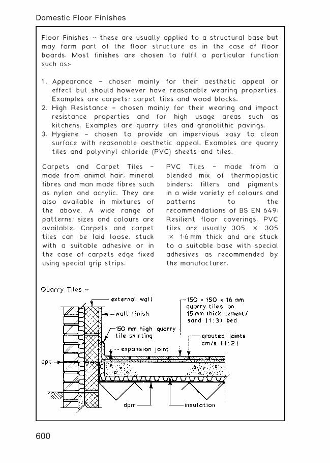
Floor Finishes ~ these are usually applied to a structural base but
may form part of the floor structure as in the case of floor
boards. Most finishes are chosen to fulfil a particular function
such as:-
1 . Appearance † chosen mainly for their aesthetic appeal or
effect but should however have reasonable wearing properties.
Examples are carpets; carpet tiles and wood blocks.
2. High Resistance † chosen mainly for their wearing and impact
resistance properties and for high usage areas such as
kitchens. Examples are quarry tiles and granolithic pavings.
3. Hygiene † chosen to provide an impervious easy to clean
surface with reasonable aesthetic appeal. Examples are quarry
tiles and polyvinyl chloride (PVC) sheets and tiles.
Carpets and Carpet Tiles †
made from animal hair, mineral
fibres and man made fibres such
as nylon and acrylic. They are
also available in mixtures of
the above. A wide range of
patterns; sizes and colours are
available. Carpets and carpet
tiles can be laid loose, stuck
with a suitable adhesive or in
the case of carpets edge fixed
using special grip strips.
PVC Tiles † made from a
blended mix of thermoplastic
binders; fillers and pigments
in a wide variety of colours and
patterns to the
recommendations of BS EN 649:
Resilient floor coverings. PVC
tiles are usually 305 � 305
� 1„6 mm thick and are stuck
to a suitable base with special
adhesives as recommended by
the manufacturer.
600
Domestic Floor Finishes
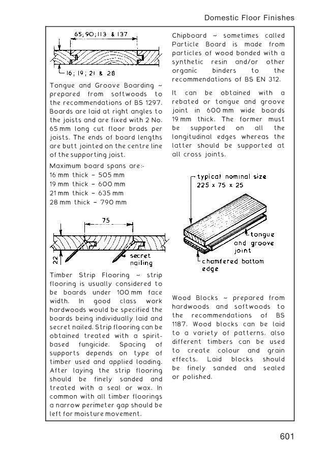
Tongue and Groove Boarding ~
prepared from softwoods to
the recommendations of BS 1297.
Boards are laid at right angles to
the joists and are fixed with 2 No.
65 mm long cut floor brads per
joists. The ends of board lengths
are butt jointed on the centre line
of the supporting joist.
Maximum board spans are:-
16 mm thick † 505 mm
19 mm thick † 600 mm
21 mm thick † 635 mm
28 mm thick † 790 mm
Timber Strip Flooring ~ strip
flooring is usually considered to
be boards under 100 mm face
width. In good class work
hardwoods would be specified the
boards being individually laid and
secret nailed. Strip flooring can be
obtained treated with a spirit-
based fungicide. Spacing of
supports depends on type of
timber used and applied loading.
After laying the strip flooring
should be finely sanded and
treated with a seal or wax. In
common with all timber floorings
a narrow perimeter gap should be
left formoisturemovement.
Chipboard ~ sometimes called
Particle Board is made from
particles of wood bonded with a
synthetic resin and/or other
organic binders to the
recommendations of BS EN 312.
It can be obtained with a
rebated or tongue and groove
joint in 600 mm wide boards
19 mm thick. The former must
be supported on all the
longitudinal edges whereas the
latter should be supported at
all cross joints.
Wood Blocks ~ prepared from
hardwoods and softwoods to
the recommendations of BS
1187. Wood blocks can be laid
to a variety of patterns, also
different timbers can be used
to create colour and grain
effects. Laid blocks should
be finely sanded and sealed
or polished.
601
Domestic Floor Finishes
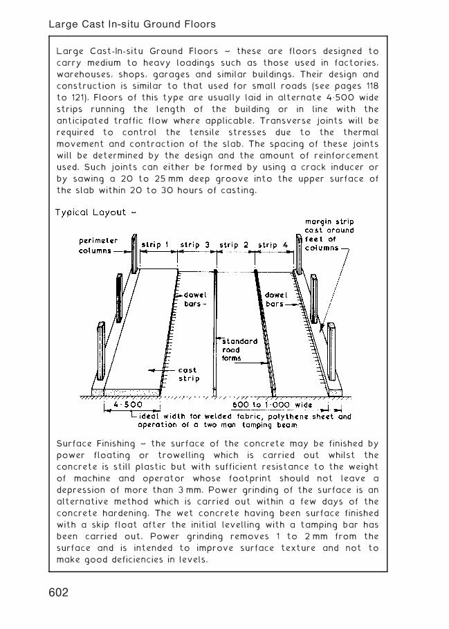
Large Cast-In-situ Ground Floors ~ these are floors designed to
carry medium to heavy loadings such as those used in factories,
warehouses, shops, garages and similar buildings. Their design and
construction is similar to that used for small roads (see pages 118
to 121). Floors of this type are usually laid in alternate 4„500 wide
strips running the length of the building or in line with the
anticipated traffic flow where applicable. Transverse joints will be
required to control the tensile stresses due to the thermal
movement and contraction of the slab. The spacing of these joints
will be determined by the design and the amount of reinforcement
used. Such joints can either be formed by using a crack inducer or
by sawing a 20 to 25 mm deep groove into the upper surface of
the slab within 20 to 30 hours of casting.
Surface Finishing ~ the surface of the concrete may be finished by
power floating or trowelling which is carried out whilst the
concrete is still plastic but with sufficient resistance to the weight
of machine and operator whose footprint should not leave a
depression of more than 3 mm. Power grinding of the surface is an
alternative method which is carried out within a few days of the
concrete hardening. The wet concrete having been surface finished
with a skip float after the initial levelling with a tamping bar has
been carried out. Power grinding removes 1 to 2 mm from the
surface and is intended to improve surface texture and not to
make good deficiencies in levels.
602
Large Cast In-situ Ground Floors
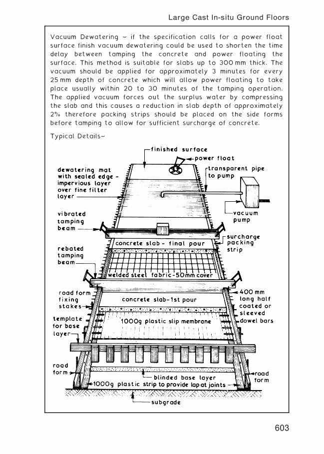
Vacuum Dewatering ~ if the specification calls for a power float
surface finish vacuum dewatering could be used to shorten the time
delay between tamping the concrete and power floating the
surface. This method is suitable for slabs up to 300 mm thick. The
vacuum should be applied for approximately 3 minutes for every
25 mm depth of concrete which will allow power floating to take
place usually within 20 to 30 minutes of the tamping operation.
The applied vacuum forces out the surplus water by compressing
the slab and this causes a reduction in slab depth of approximately
2% therefore packing strips should be placed on the side forms
before tamping to allow for sufficient surcharge of concrete.
Typical Details~
603
Large Cast In-situ Ground Floors
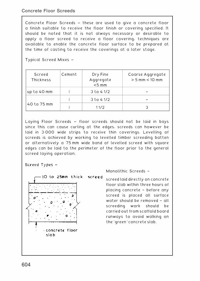
Concrete Floor Screeds ~ these are used to give a concrete floor
a finish suitable to receive the floor finish or covering specified. It
should be noted that it is not always necessary or desirable to
apply a floor screed to receive a floor covering, techniques are
available to enable the concrete floor surface to be prepared at
the time of casting to receive the coverings at a later stage.
Typical Screed Mixes ~
Laying Floor Screeds ~ floor screeds should not be laid in bays
since this can cause curling at the edges, screeds can however be
laid in 3„000 wide strips to receive thin coverings. Levelling of
screeds is achieved by working to levelled timber screeding batten
or alternatively a 75 mm wide band of levelled screed with square
edges can be laid to the perimeter of the floor prior to the general
screed laying operation.
Monolithic Screeds †
screed laid directly on concrete
floor slab within three hours of
placing concrete † before any
screed is placed all surface
water should be removed † all
screeding work should be
carried out from scaffold board
runways to avoid walking on
the `green' concrete slab.
Screed
Thickness
Cement Dry Fine
Aggregate
<5 mm
Coarse Aggregate
> 5 mm < 10 mm
up to 40 mm | 3 to 4 1/2 †
40 to 75 mm| 3 to 4 1/2 †
| 1 1/2 3
604
Concrete Floor Screeds
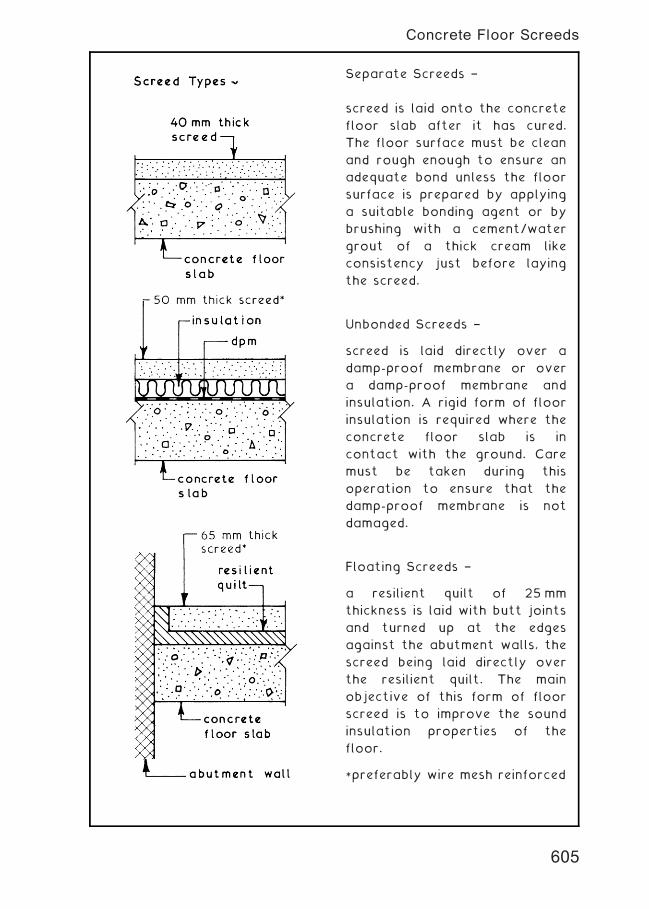
Separate Screeds †
screed is laid onto the concrete
floor slab after it has cured.
The floor surface must be clean
and rough enough to ensure an
adequate bond unless the floor
surface is prepared by applying
a suitable bonding agent or by
brushing with a cement/water
grout of a thick cream like
consistency just before laying
the screed.
Unbonded Screeds †
screed is laid directly over a
damp-proof membrane or over
a damp-proof membrane and
insulation. A rigid form of floor
insulation is required where the
concrete floor slab is in
contact with the ground. Care
must be taken during this
operation to ensure that the
damp-proof membrane is not
damaged.
Floating Screeds †
a resilient quilt of 25 mm
thickness is laid with butt joints
and turned up at the edges
against the abutment walls, the
screed being laid directly over
the resilient quilt. The main
objective of this form of floor
screed is to improve the sound
insulation properties of the
floor.
*preferably wire mesh reinforced
605
Concrete Floor Screeds
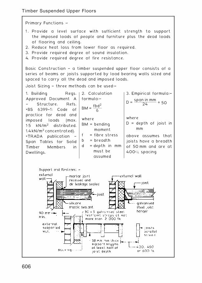
Primary Functions ~
1 . Provide a level surface with sufficient strength to support
the imposed loads of people and furniture plus the dead loads
of flooring and ceiling.
2. Reduce heat loss from lower floor as required.
3. Provide required degree of sound insulation.
4. Provide required degree of fire resistance.
Basic Construction † a timber suspended upper floor consists of a
series of beams or joists supported by load bearing walls sized and
spaced to carry all the dead and imposed loads.
Joist Sizing † three methods can be used:†
1. Building Regs.
Approved Document A
† Structure. Refs.
*BS 6399†1: Code of
practice for dead and
imposed loads (max.
1„5 kN/m2 distributed,
1.4kN/m2 concentrated).
*TRADA publication †
Span Tables for Solid
Timber Members in
Dwellings.
2. Calculation
formula:†
BM =fbd2
6
where
BM = bending
moment
f = fibre stress
b = breadth
d = depth in mm
must be
assumed
3. Empirical formula:†
D =span in mm
24 + 50
where
D = depth of joist in
mm
above assumes that
joists have a breadth
of 50 mm and are at
400c=c spacing
606
Timber Suspended Upper Floors
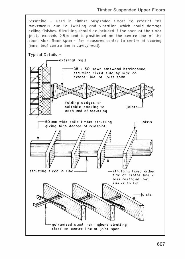
Strutting ~ used in timber suspended floors to restrict the
movements due to twisting and vibration which could damage
ceiling finishes. Strutting should be included if the span of the floor
joists exceeds 2„5m and is positioned on the centre line of the
span. Max. floor span ~ 6m measured centre to centre of bearing
(inner leaf centre line in cavity wall).
607
Timber Suspended Upper Floors
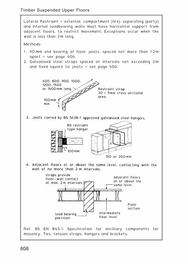
Lateral Restraint ~ external, compartment (fire), separating (party)
and internal loadbearing walls must have horizontal support from
adjacent floors, to restrict movement. Exceptions occur when the
wall is less than 3m long.
Methods:
1 . 90 mm end bearing of floor joists, spaced not more than 1„2m
apart † see page 606.
2. Galvanised steel straps spaced at intervals not exceeding 2m
and fixed square to joists † see page 606.
Ref. BS EN 845-1: Specification for ancillary components for
masonry. Ties, tension straps, hangers and brackets.
608
Timber Suspended Upper Floors
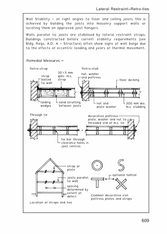
Wall Stability † at right angles to floor and ceiling joists this is
achieved by building the joists into masonry support walls or
locating them on approved joist hangers.
Walls parallel to joists are stabilised by lateral restraint straps.
Buildings constructed before current stability requirements (see
Bldg. Regs. A.D; A † Structure) often show signs of wall bulge due
to the effects of eccentric loading and years of thermal movement.
609
Lateral Restraint---Retro-ties
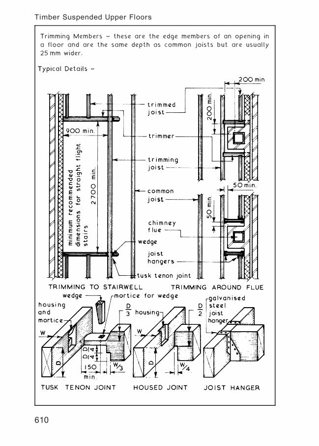
Trimming Members ~ these are the edge members of an opening in
a floor and are the same depth as common joists but are usually
25 mm wider.
610
Timber Suspended Upper Floors
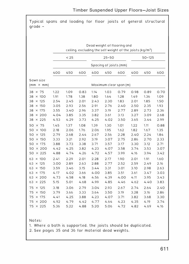
Typical spans and loading for floor joists of general structural
grade †
Dead weight of flooring and
ceiling, excluding the self weight of the joists (kg/m2)
< 25 25†50 50†125
Spacing of joists (mm)
400 450 600 400 450 600 400 450 600
Sawn size
(mm � mm) Maximum clear span (m)
38 � 75 1.22 1.09 0.83 1.14 1.03 0.79 0.98 0.89 0.70
38 � 100 1.91 1.78 1.38 1.80 1.64 1.28 1.49 1.36 1.09
38 � 125 2.54 2.45 2.01 2.43 2.30 1.83 2.01 1.85 1.50
38 � 150 3.05 2.93 2.56 2.91 2.76 2.40 2.50 2.35 1.93
38 � 175 3.55 3.40 2.96 3.37 3.19 2.77 2.89 2.73 2.36
38 � 200 4.04 3.85 3.35 3.82 3.61 3.13 3.27 3.09 2.68
38 � 225 4.53 4.29 3.73 4.25 4.02 3.50 3.65 3.44 2.99
50 � 75 1.45 1.37 1.08 1.39 1.30 1.01 1.22 1.11 0.88
50 � 100 2.18 2.06 1.76 2.06 1.95 1.62 1.82 1.67 1.35
50 � 125 2.79 2.68 2.44 2.67 2.56 2.28 2.40 2.24 1.84
50 � 150 3.33 3.21 2.92 3.19 3.07 2.75 2.86 2.70 2.33
50 � 175 3.88 3.73 3.38 3.71 3.57 3.17 3.30 3.12 2.71
50 � 200 4.42 4.25 3.82 4.23 4.07 3.58 3.74 3.53 3.07
50 � 225 4.88 4.74 4.26 4.72 4.57 3.99 4.16 3.94 3.42
63 � 100 2.41 2.29 2.01 2.28 2.17 1.90 2.01 1.91 1.60
63 � 125 3.00 2.89 2.63 2.88 2.77 2.52 2.59 2.49 2.16
63 � 150 3.59 3.46 3.15 3.44 3.31 3.01 3.10 2.98 2.63
63 � 175 4.17 4.02 3.66 4.00 3.85 3.51 3.61 3.47 3.03
63 � 200 4.73 4.58 4.18 4.56 4.39 4.00 4.11 3.95 3.43
63 � 225 5.15 5.01 4.68 4.99 4.85 4.46 4.62 4.40 3.83
75 � 125 3.18 3.06 2.79 3.04 2.93 2.67 2.74 2.64 2.40
75 � 150 3.79 3.66 3.33 3.64 3.50 3.19 3.28 3.16 2.86
75 � 175 4.41 4.25 3.88 4.23 4.07 3.71 3.82 3.68 3.30
75 � 200 4.92 4.79 4.42 4.77 4.64 4.23 4.35 4.19 3.74
75 � 225 5.36 5.22 4.88 5.20 5.06 4.72 4.82 4.69 4.16
Notes:
1. Where a bath is supported, the joists should be duplicated.
2. See pages 35 and 36 for material dead weights.
611
Timber Suspended Upper Floors---Joist Sizes
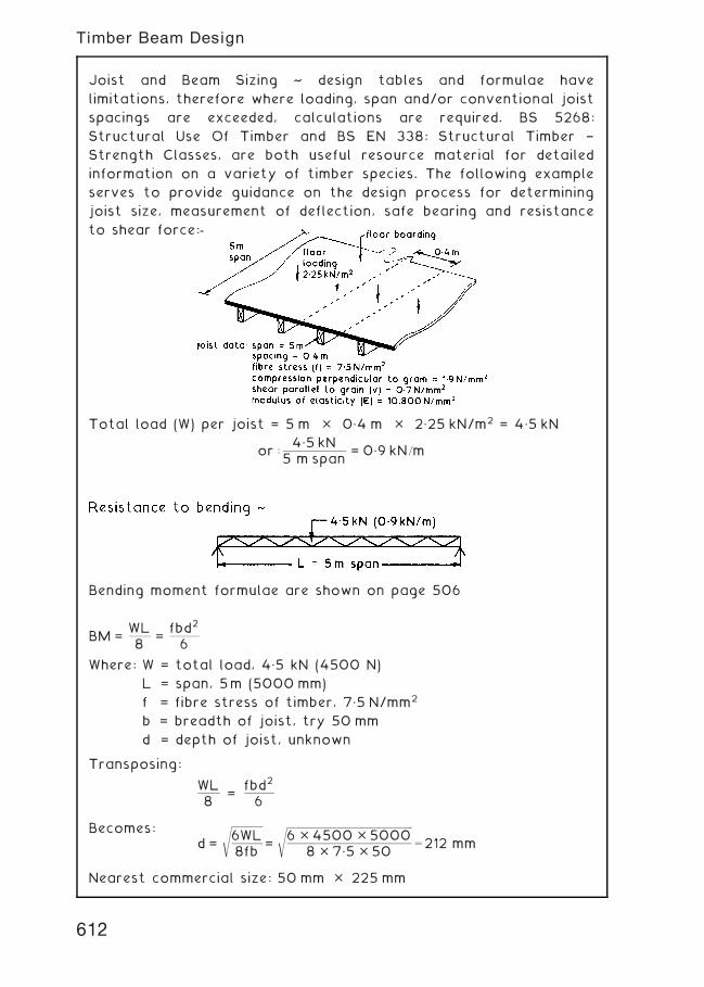
Joist and Beam Sizing ~ design tables and formulae have
limitations, therefore where loading, span and/or conventional joist
spacings are exceeded, calculations are required. BS 5268:
Structural Use Of Timber and BS EN 338: Structural Timber †
Strength Classes, are both useful resource material for detailed
information on a variety of timber species. The following example
serves to provide guidance on the design process for determining
joist size, measurement of deflection, safe bearing and resistance
to shear force:-
Total load (W) per joist = 5 m � 0„4 m � 2„25 kN/m2 = 4„5 kN
or :4„5 kN
5 m span= 0„9 kN=m
Bending moment formulae are shown on page 506
BM =WL8
=fbd2
6
Where: W = total load, 4„5 kN (4500 N)
L = span, 5m (5000 mm)
f = fibre stress of timber, 7„5 N/mm2
b = breadth of joist, try 50 mm
d = depth of joist, unknown
Transposing:
WL8
=fbd2
6
Becomes:d =
ffiffiffiffiffiffiffiffiffiffiffiffiffiffiffi
6WL8fb
s
=
ffiffiffiffiffiffiffiffiffiffiffiffiffiffiffiffiffiffiffiffiffiffiffiffiffiffiffiffiffiffiffiffiffiffiffiffiffiffiffiffiffiffiffiffiffiffiffiffiffiffiffiffiffiffiffiffiffiffiffiffi
6 � 4500 � 50008 � 7„5 � 50
s
¼ 212 mm
Nearest commercial size: 50 mm � 225 mm
612
Timber Beam Design
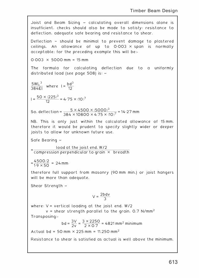
Joist and Beam Sizing ~ calculating overall dimensions alone is
insufficient, checks should also be made to satisfy: resistance to
deflection, adequate safe bearing and resistance to shear.
Deflection † should be minimal to prevent damage to plastered
ceilings. An allowance of up to 0„003 � span is normally
acceptable; for the preceding example this will be:-
0„003 � 5000 mm = 15 mm
The formula for calculating deflection due to a uniformly
distributed load (see page 508) is: ~
5WL3
384Elwhere l =
bd3
12
l =50 � ð225Þ3
12= 4„75 � ð10Þ7
So, deflection = 5 � 4500 � ð5000Þ3
384 � 10800 � 4:75 � ð10Þ7= 14„27mm
NB. This is only just within the calculated allowance of 15 mm,
therefore it would be prudent to specify slightly wider or deeper
joists to allow for unknown future use.
Safe Bearing ~
=load at the joist end, W/2
compression perpendicular to grain � breadth
=4500=21„9 � 50
= 24mm:
therefore full support from masonry (90 mm min.) or joist hangers
will be more than adequate.
Shear Strength ~
V =2bdv3
where: V = vertical loading at the joist end, W/2
v = shear strength parallel to the grain, 0.7 N/mm2
Transposing:-
bd =3V2v
=3 � 22502 � 0:7
= 4821 mm2 minimum
Actual bd = 50 mm � 225 mm = 11,250 mm2
Resistance to shear is satisfied as actual is well above the minimum.
613
Timber Beam Design
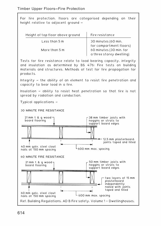
For fire protection, floors are categorised depending on their
height relative to adjacent ground ~
Tests for fire resistance relate to load bearing capacity, integrity
and insulation as determined by BS 476: Fire tests on building
materials and structures. Methods of test for fire propagation for
products.
Integrity ~ the ability of an element to resist fire penetration and
capacity to bear load in a fire.
Insulation ~ ability to resist heat penetration so that fire is not
spread by radiation and conduction.
Typical applications ~
38 mm timber joists withnoggins or struts tosupport board edges
12.5 mm plasterboard,joints taped and filled
50 mm timber joists withnoggins or struts tosupport board edges
two layers of 15 mmplasterboardindependentlynailed with jointstaped and filled
600 mm max. spacing
600 mm max. spacing
40 mm galv. steel cloutnails at 150 mm spacing
60 mm galv. steel cloutnails at 150 mm spacing
21 mm t & g woodboard flooring
21 mm t & g woodboard flooring
30 MINUTE FIRE RESISTANCE
60 MINUTE FIRE RESISTANCE
Ref. Building Regulations, AD B Fire safety, Volume 1 † Dwellinghouses.
Height of top floor above ground Fire resistance
Less than 5 m 30 minutes (60 min.
for compartment floors)
More than 5 m 60 minutes (30 min. for
a three storey dwelling)
614
Timber Upper Floors---Fire Protection
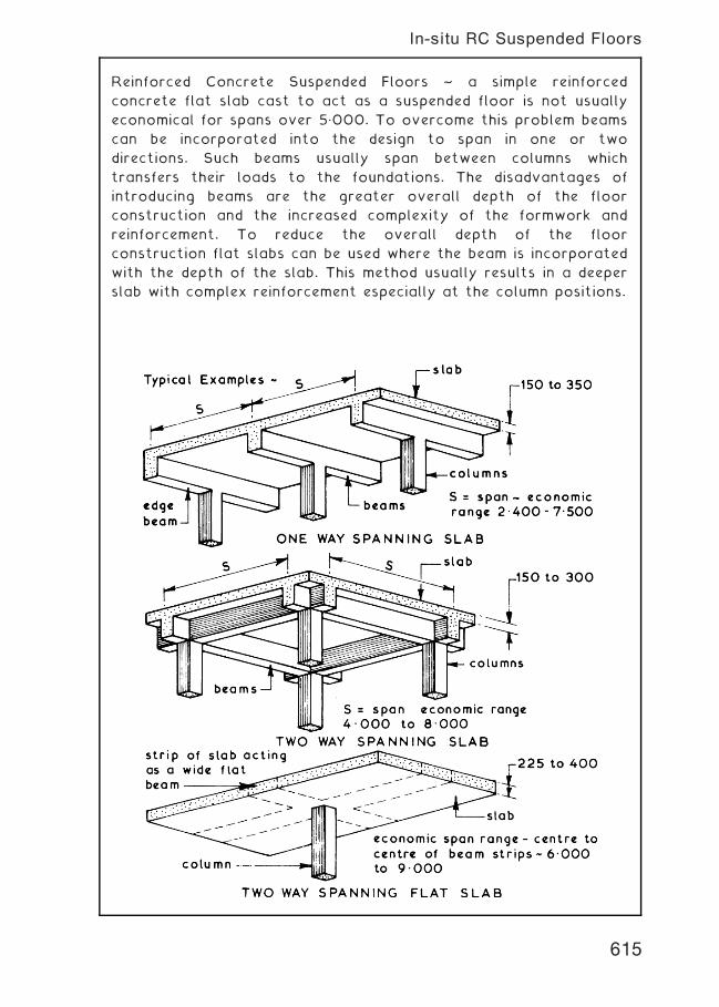
Reinforced Concrete Suspended Floors ~ a simple reinforced
concrete flat slab cast to act as a suspended floor is not usually
economical for spans over 5„000. To overcome this problem beams
can be incorporated into the design to span in one or two
directions. Such beams usually span between columns which
transfers their loads to the foundations. The disadvantages of
introducing beams are the greater overall depth of the floor
construction and the increased complexity of the formwork and
reinforcement. To reduce the overall depth of the floor
construction flat slabs can be used where the beam is incorporated
with the depth of the slab. This method usually results in a deeper
slab with complex reinforcement especially at the column positions.
615
In-situ RC Suspended Floors
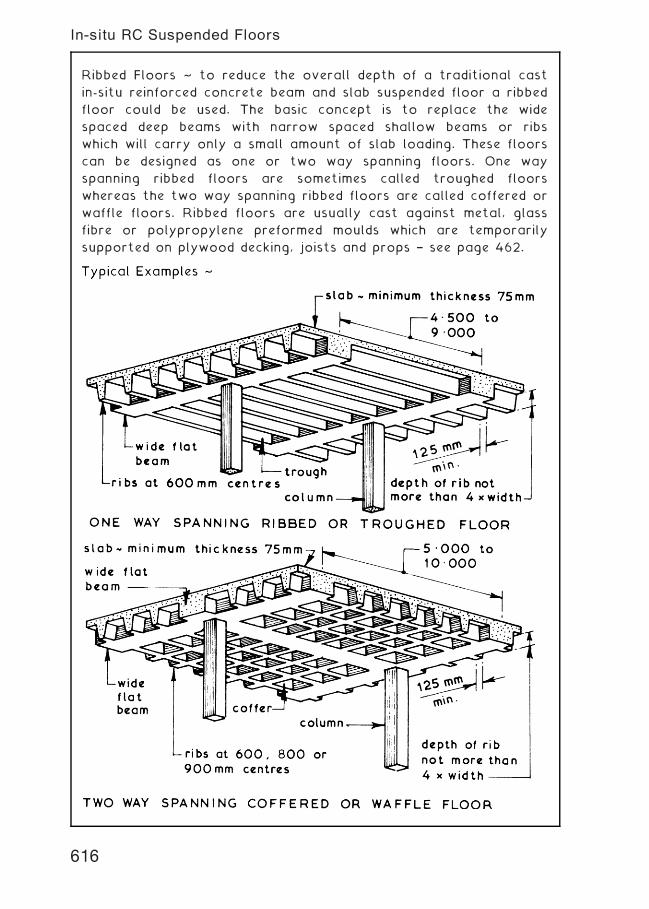
Ribbed Floors ~ to reduce the overall depth of a traditional cast
in-situ reinforced concrete beam and slab suspended floor a ribbed
floor could be used. The basic concept is to replace the wide
spaced deep beams with narrow spaced shallow beams or ribs
which will carry only a small amount of slab loading. These floors
can be designed as one or two way spanning floors. One way
spanning ribbed floors are sometimes called troughed floors
whereas the two way spanning ribbed floors are called coffered or
waffle floors. Ribbed floors are usually cast against metal, glass
fibre or polypropylene preformed moulds which are temporarily
supported on plywood decking, joists and props † see page 462.
616
In-situ RC Suspended Floors
Ribbed Floors † these have greater span and load potential per
unit weight than flat slab construction. This benefits a considerable
reduction in dead load, to provide cost economies in other super-
structural elements and foundations. The regular pattern of voids
created with waffle moulds produces a honeycombed effect, which
may be left exposed in utility buildings such as car parks.
Elsewhere such as shopping malls, a suspended ceiling would be
appropriate. The trough finish is also suitable in various situations
and has the advantage of creating a continuous void for
accommodation of service cables and pipes. A suspended ceiling can
add to this space where air conditioning ducting is required, also
providing several options for finishing effect.
Note: After removing the temporary support structure, moulds are
struck by flexing with a flat tool. A compressed air line is also
effective.
617
In-situ RC Suspended Floors

Hollow Pot Floors ~ these are in essence a ribbed floor with
permanent formwork in the form of hollow clay or concrete pots.
The main advantage of this type of cast in-situ floor is that it has
a flat soffit which is suitable for the direct application of a plaster
finish or an attached dry lining. The voids in the pots can be
utilised to house small diameter services within the overall depth
of the slab. These floors can be designed as one or two way
spanning slabs, the common format being the one way spanning
floor.
618
In-situ RC Suspended Floors
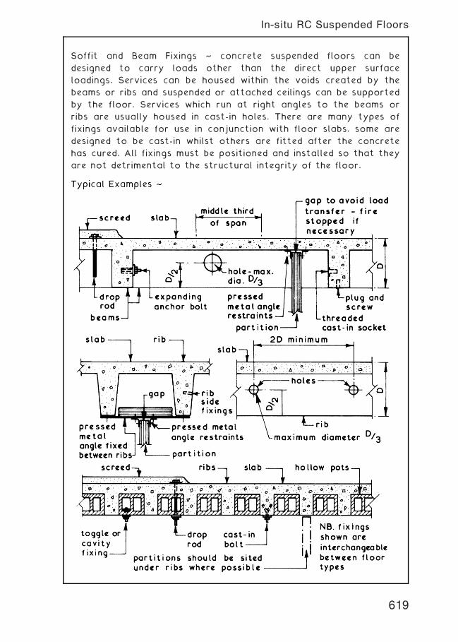
Soffit and Beam Fixings ~ concrete suspended floors can be
designed to carry loads other than the direct upper surface
loadings. Services can be housed within the voids created by the
beams or ribs and suspended or attached ceilings can be supported
by the floor. Services which run at right angles to the beams or
ribs are usually housed in cast-in holes. There are many types of
fixings available for use in conjunction with floor slabs, some are
designed to be cast-in whilst others are fitted after the concrete
has cured. All fixings must be positioned and installed so that they
are not detrimental to the structural integrity of the floor.
619
In-situ RC Suspended Floors
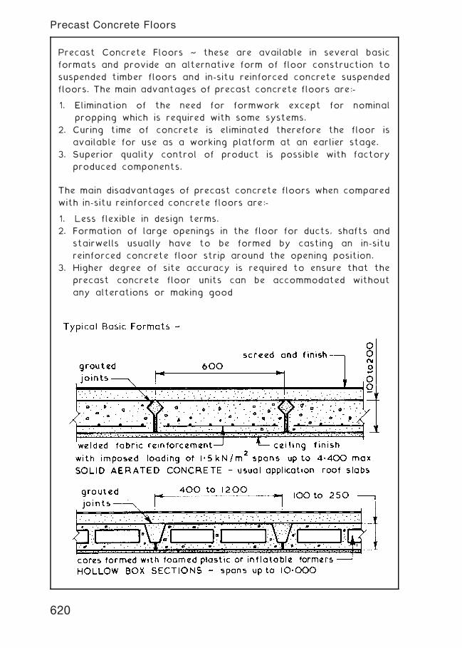
Precast Concrete Floors ~ these are available in several basic
formats and provide an alternative form of floor construction to
suspended timber floors and in-situ reinforced concrete suspended
floors. The main advantages of precast concrete floors are:-
1. Elimination of the need for formwork except for nominal
propping which is required with some systems.
2. Curing time of concrete is eliminated therefore the floor is
available for use as a working platform at an earlier stage.
3. Superior quality control of product is possible with factory
produced components.
The main disadvantages of precast concrete floors when compared
with in-situ reinforced concrete floors are:-
1. Less flexible in design terms.
2. Formation of large openings in the floor for ducts, shafts and
stairwells usually have to be formed by casting an in-situ
reinforced concrete floor strip around the opening position.
3. Higher degree of site accuracy is required to ensure that the
precast concrete floor units can be accommodated without
any alterations or making good
620
Precast Concrete Floors
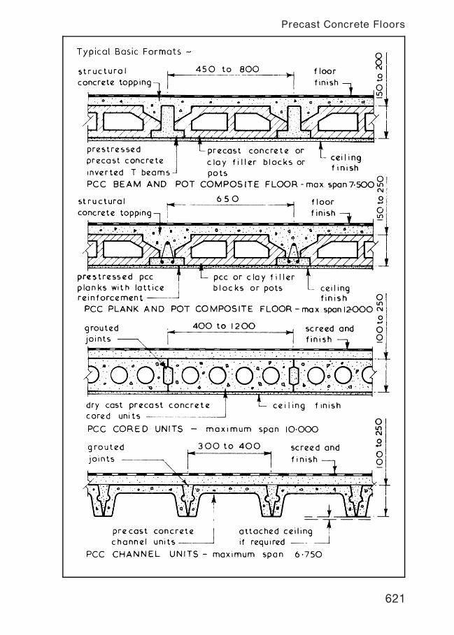
621
Precast Concrete Floors
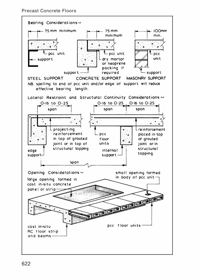
622
Precast Concrete Floors
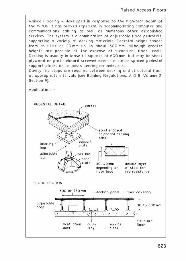
Raised Flooring ~ developed in response to the high-tech boom of
the 1970s. It has proved expedient in accommodating computer and
communications cabling as well as numerous other established
services. The system is a combination of adjustable floor pedestals,
supporting a variety of decking materials. Pedestal height ranges
from as little as 30mm up to about 600mm, although greater
heights are possible at the expense of structural floor levels.
Decking is usually in loose fit squares of 600mm, but may be sheet
plywood or particleboard screwed direct to closer spaced pedestal
support plates on to joists bearing on pedestals.
Cavity fire stops are required between decking and structural floor
at appropriate intervals (see Building Regulations, A D B, Volume 2,
Section 9).
623
Raised Access Floors
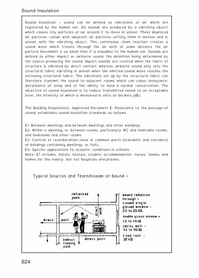
Sound Insulation ~ sound can be defined as vibrations of air which are
registered by the human ear. All sounds are produced by a vibrating object
which causes tiny particles of air around it to move in unison. These displaced
air particles collide with adjacent air particles setting them in motion and in
unison with the vibrating object. This continuous chain reaction creates a
sound wave which travels through the air until at some distance the air
particle movement is so small that it is inaudible to the human ear. Sounds are
defined as either impact or airborne sound, the definition being determined by
the source producing the sound. Impact sounds are created when the fabric of
structure is vibrated by direct contact whereas airborne sound only sets the
structural fabric vibrating in unison when the emitted sound wave reaches the
enclosing structural fabric. The vibrations set up by the structural fabric can
therefore transmit the sound to adjacent rooms which can cause annoyance,
disturbance of sleep and of the ability to hold a normal conservation. The
objective of sound insulation is to reduce transmitted sound to an acceptable
level, the intensity of which is measured in units of decibels (dB).
The Building Regulations, Approved Document E: Resistance to the passage of
sound, establishes sound insulation standards as follows
E1: Between dwellings and between dwellings and other buildings.
E2: Within a dwelling, ie. between rooms, particularly WC and habitable rooms,
and bedrooms and other rooms.
E3: Control of reverberation noise in common parts (stairwells and corridors)
of buildings containing dwellings, ie. flats.
E4: Specific applications to acoustic conditions in schools.
Note: E1 includes, hotels, hostels, student accommodation, nurses' homes and
homes for the elderly, but not hospitals and prisons.
624
Sound Insulation
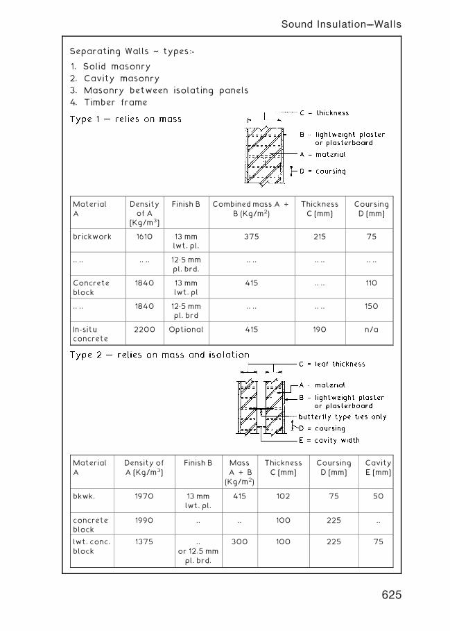
Separating Walls ~ types:-
1. Solid masonry
2. Cavity masonry
3. Masonry between isolating panels
4. Timber frame
MaterialA
Densityof A
[Kg/m3]
Finish B Combined mass A +B (Kg/m2)
ThicknessC [mm]
CoursingD [mm]
brickwork 1610 13 mmlwt. pl.
375 215 75
.. .. .. .. 12„5 mmpl. brd.
.. .. .. .. .. ..
Concreteblock
1840 13 mmlwt. pl
415 .. .. 110
.. .. 1840 12„5 mmpl. brd
.. .. .. .. 150
In-situconcrete
2200 Optional 415 190 n/a
MaterialA
Density ofA [Kg/m3]
Finish B MassA + B
(Kg/m2)
ThicknessC [mm]
CoursingD [mm]
CavityE [mm]
bkwk. 1970 13 mmlwt. pl.
415 102 75 50
concreteblock
1990 .. .. 100 225 ..
lwt. conc.block
1375 ..or 12.5 mmpl. brd.
300 100 225 75
625
Sound Insulation---Walls
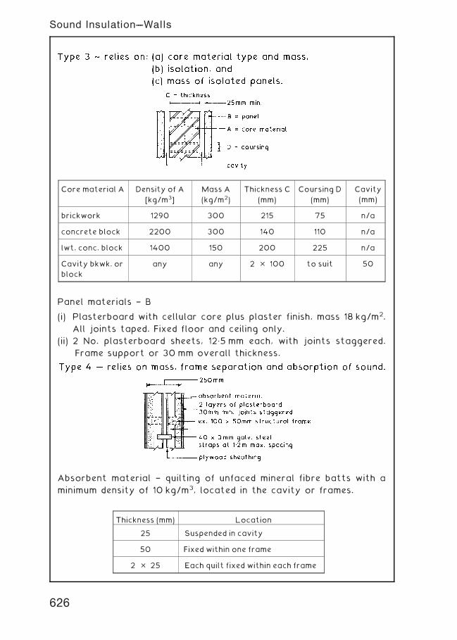
Panel materials † B
(i) Plasterboard with cellular core plus plaster finish, mass 18 kg/m2.
All joints taped. Fixed floor and ceiling only.
(ii) 2 No. plasterboard sheets, 12„5 mm each, with joints staggered.
Frame support or 30 mm overall thickness.
Absorbent material † quilting of unfaced mineral fibre batts with a
minimum density of 10 kg/m3, located in the cavity or frames.
Core material A Density of A
[kg/m3]
Mass A
(kg/m2)
Thickness C
(mm)
Coursing D
(mm)
Cavity
(mm)
brickwork 1290 300 215 75 n/a
concrete block 2200 300 140 110 n/a
lwt. conc. block 1400 150 200 225 n/a
Cavity bkwk. or
block
any any 2 � 100 to suit 50
Thickness (mm) Location
25 Suspended in cavity
50 Fixed within one frame
2 � 25 Each quilt fixed within each frame
626
Sound Insulation---Walls
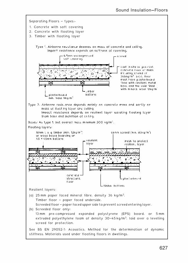
Separating Floors ~ types:-
1. Concrete with soft covering
2. Concrete with floating layer
3. Timber with floating layer
Resilient layers:
(a) 25 mm paper faced mineral fibre, density 36 kg/m3.
Timber floor † paper faced underside.
Screeded floor † paper faced upper side toprevent screed entering layer.
(b) Screeded floor only:
13 mm pre-compressed expanded polystyrene (EPS) board, or 5 mm
extruded polyethylene foam of density 30†45 kg/m3, laid over a levelling
screed for protection.
See BS EN 29052-1: Acoustics. Method for the determination of dynamic
stiffness. Materials used under floating floors in dwellings.
627
Sound Insulation---Floors
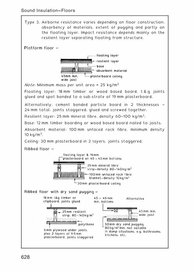
Type 3. Airborne resistance varies depending on floor construction,
absorbency of materials, extent of pugging and partly on
the floating layer. Impact resistance depends mainly on the
resilient layer separating floating from structure.
Note: Minimum mass per unit area = 25 kg/m2
Floating layer: 18 mm timber or wood based board, t & g joints
glued and spot bonded to a sub-strate of 19 mm plasterboard.
Alternatively, cement bonded particle board in 2 thicknesses †
24 mm total, joints staggered, glued and screwed together.
Resilient layer: 25 mm mineral fibre, density 60†100 kg/m3.
Base: 12 mm timber boarding or wood based board nailed to joists.
Absorbent material: 100 mm unfaced rock fibre, minimum density
10 kg/m3.
Ceiling: 30 mm plasterboard in 2 layers, joints staggered.
628
Sound Insulation---Floors
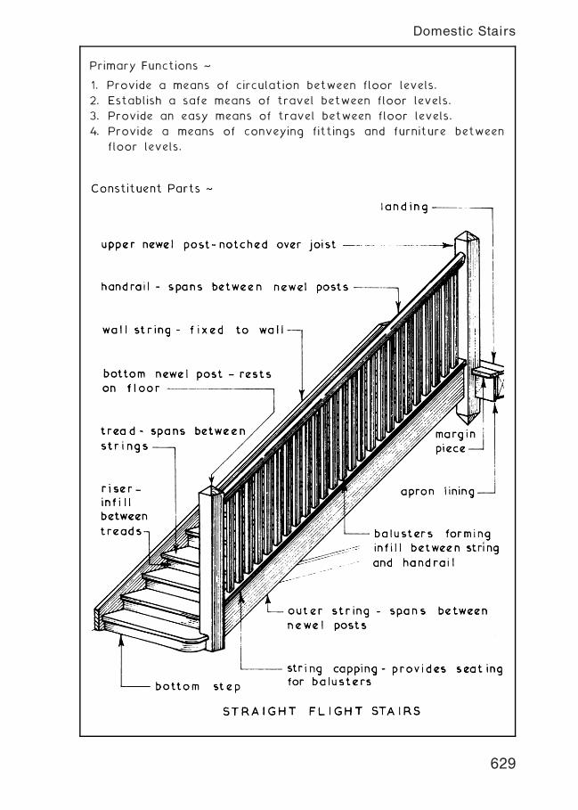
Primary Functions ~
1. Provide a means of circulation between floor levels.
2. Establish a safe means of travel between floor levels.
3. Provide an easy means of travel between floor levels.
4. Provide a means of conveying fittings and furniture between
floor levels.
629
Domestic Stairs
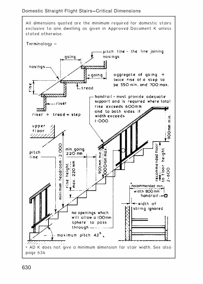
All dimensions quoted are the minimum required for domestic stairs
exclusive to one dwelling as given in Approved Document K unless
stated otherwise.
* AD K does not give a minimum dimension far stair width. See also
page 634
630
Domestic Straight Flight Stairs---Critical Dimensions
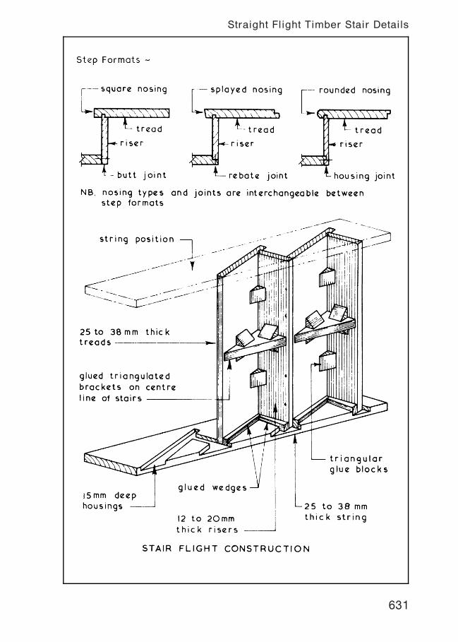
631
Straight Flight Timber Stair Details
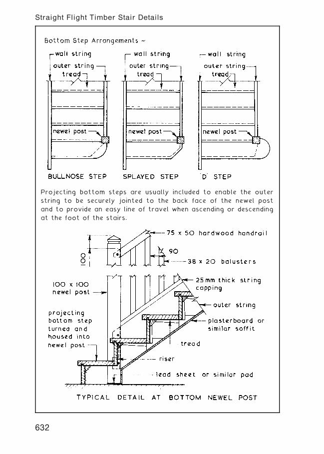
Projecting bottom steps are usually included to enable the outer
string to be securely jointed to the back face of the newel post
and to provide an easy line of travel when ascending or descending
at the foot of the stairs.
632
Straight Flight Timber Stair Details
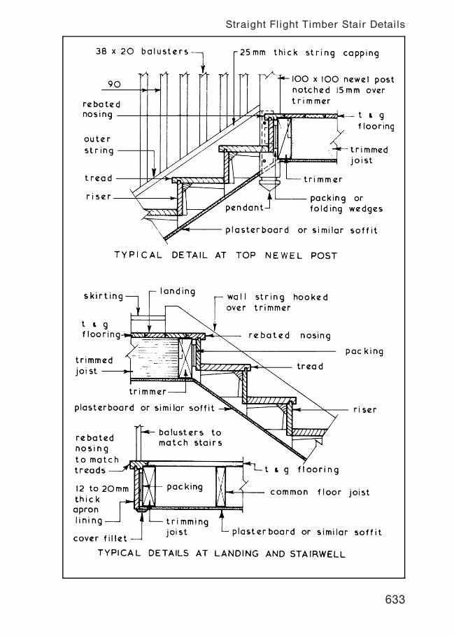
633
Straight Flight Timber Stair Details
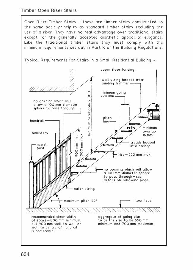
Open Riser Timber Stairs ~ these are timber stairs constructed to
the same basic principles as standard timber stairs excluding the
use of a riser. They have no real advantage over traditional stairs
except for the generally accepted aesthetic appeal of elegance.
Like the traditional timber stairs they must comply with the
minimum requirements set out in Part K of the Building Regulations.
Typical Requirements for Stairs in a Small Residential Building ~
upper floor landing
wall string hooked overlanding trimmer
minimum going220 mm
pitchline
outer string
floor level
rise … 220 mm max.
treads housedinto strings
minimumoverlap16 mm
maximum pitch 42ƒ
recommended clear widthof stairs … 800 mm minimum,but 900 mm wall to wall or wall to centre of handrailis preferable
aggregate of going plustwice the rise to be 550 mmminimum and 700 mm maximum
no opening which will allowa 100 mm diameter sphereto pass through … seedetails on following page
no opening which willallow a 100 mm diametersphere to pass through
handrail
balusters
newelpost
minim
um h
eadro
om 2
.000
900
mm m
in.
1000
mm m
ax.
634
Timber Open Riser Stairs
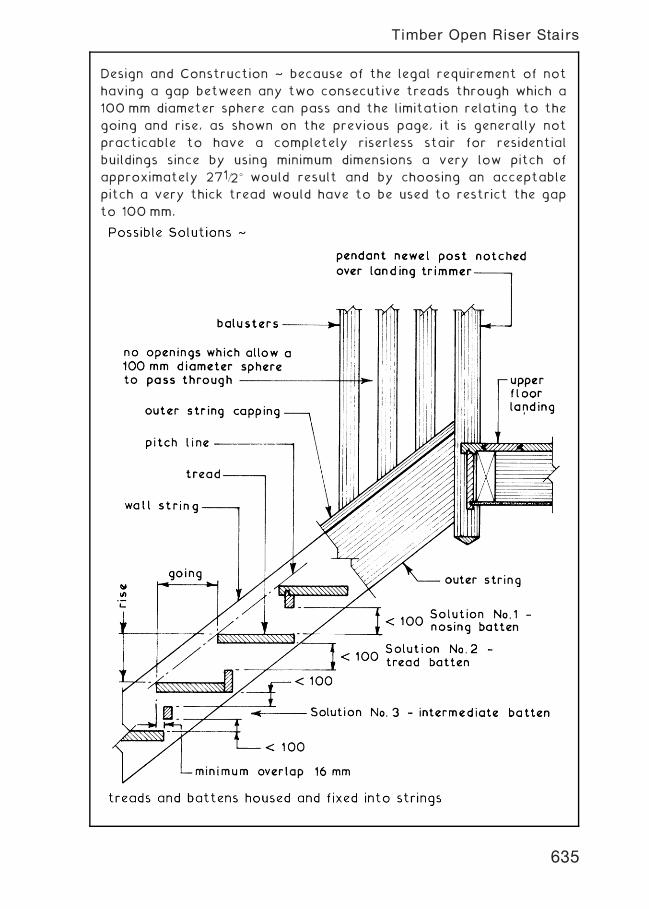
Design and Construction ~ because of the legal requirement of not
having a gap between any two consecutive treads through which a
100 mm diameter sphere can pass and the limitation relating to the
going and rise, as shown on the previous page, it is generally not
practicable to have a completely riserless stair for residential
buildings since by using minimum dimensions a very low pitch of
approximately 271=2� would result and by choosing an acceptable
pitch a very thick tread would have to be used to restrict the gap
to 100 mm.
635
Timber Open Riser Stairs
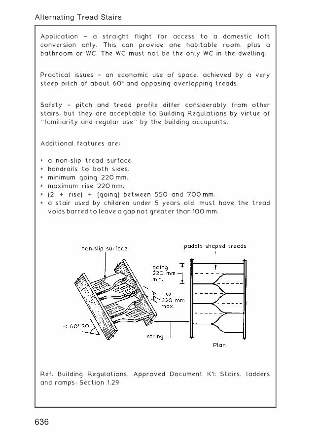
Application † a straight flight for access to a domestic loft
conversion only. This can provide one habitable room, plus a
bathroom or WC. The WC must not be the only WC in the dwelling.
Practical issues † an economic use of space, achieved by a very
steep pitch of about 60� and opposing overlapping treads.
Safety † pitch and tread profile differ considerably from other
stairs, but they are acceptable to Building Regulations by virtue of
``familiarity and regular use'' by the building occupants.
Additional features are:
* a non-slip tread surface.
* handrails to both sides.
* minimum going 220 mm.
* maximum rise 220 mm.
* (2 + rise) + (going) between 550 and 700 mm.
* a stair used by children under 5 years old, must have the tread
voids barred to leave a gap not greater than 100 mm.
Ref. Building Regulations, Approved Document K1: Stairs, ladders
and ramps: Section 1.29
636
Alternating Tread Stairs
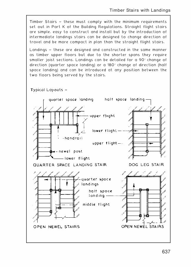
Timber Stairs ~ these must comply with the minimum requirements
set out in Part K of the Building Regulations. Straight flight stairs
are simple, easy to construct and install but by the introduction of
intermediate landings stairs can be designed to change direction of
travel and be more compact in plan than the straight flight stairs.
Landings ~ these are designed and constructed in the same manner
as timber upper floors but due to the shorter spans they require
smaller joist sections. Landings can be detailed for a 90� change of
direction (quarter space landing) or a 180� change of direction (half
space landing) and can be introduced at any position between the
two floors being served by the stairs.
637
Timber Stairs with Landings
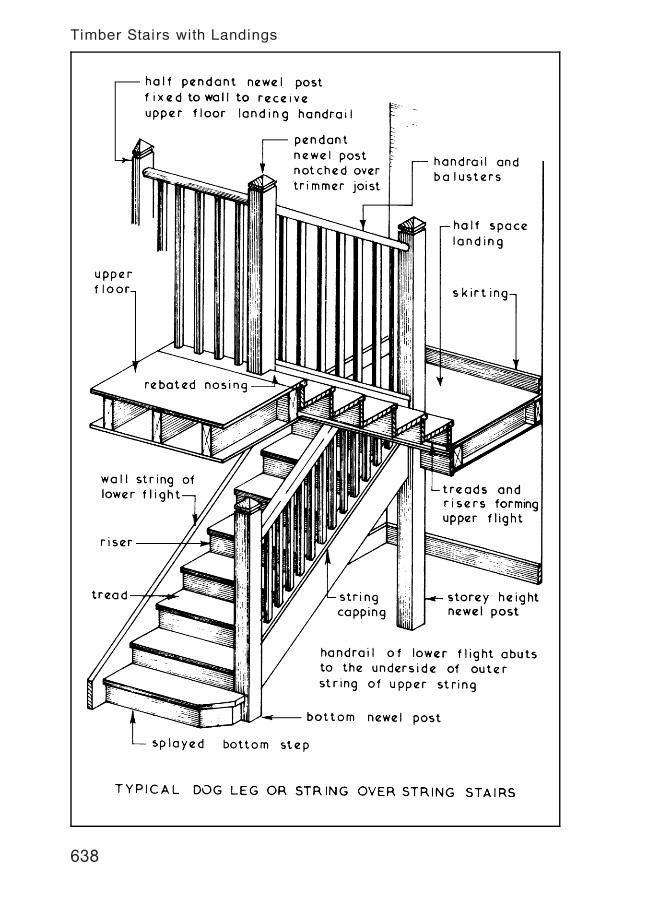
638
Timber Stairs with Landings
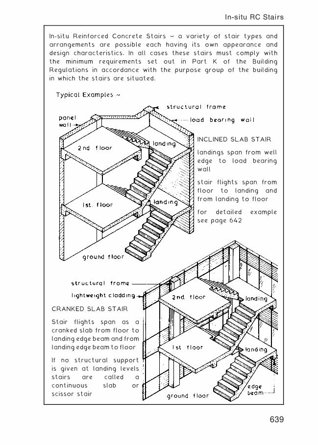
In-situ Reinforced Concrete Stairs ~ a variety of stair types and
arrangements are possible each having its own appearance and
design characteristics. In all cases these stairs must comply with
the minimum requirements set out in Part K of the Building
Regulations in accordance with the purpose group of the building
in which the stairs are situated.
INCLINED SLAB STAIR
landings span from well
edge to load bearing
wall
stair flights span from
floor to landing and
from landing to floor
for detailed example
see page 642
CRANKED SLAB STAIR
Stair flights span as a
cranked slab from floor to
landing edge beamand from
landing edge beamto floor
If no structural support
is given at landing levels
stairs are called a
continuous slab or
scissor stair
639
In-situ RC Stairs
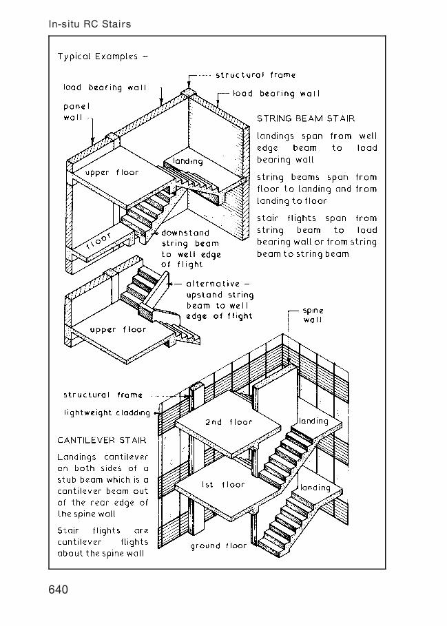
640
In-situ RC Stairs
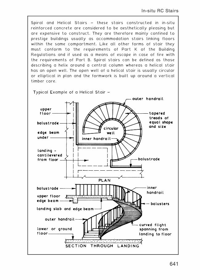
Spiral and Helical Stairs ~ these stairs constructed in in-situ
reinforced concrete are considered to be aesthetically pleasing but
are expensive to construct. They are therefore mainly confined to
prestige buildings usually as accommodation stairs linking floors
within the same compartment. Like all other forms of stair they
must conform to the requirements of Part K of the Building
Regulations and if used as a means of escape in case of fire with
the requirements of Part B. Spiral stairs can be defined as those
describing a helix around a central column whereas a helical stair
has an open well. The open well of a helical stair is usually circular
or elliptical in plan and the formwork is built up around a vertical
timber core.
641
In-situ RC Stairs
642
In-situ RC Stairs
In-situ Reinforced Concrete Stair Formwork ~ in specific detail the
formwork will vary for the different types of reinforced concrete
stair but the basic principles for each format will remain constant.
643
In-situ RC Stairs---Formwork
Precast Concrete Stairs ~ these can be produced to most of the
formats used for in-situ concrete stairs and like those must comply
with the appropriate requirements set out in Part K of the Building
Regulations. To be economic the total production run must be
sufficient to justify the costs of the moulds and therefore the
designers choice may be limited to the stair types which are
produced as a manufacturer's standard item.
Precast concrete stairs can have the following advantages:†
1 . Good quality control of finished product.
2. Saving in site space since formwork fabrication and storage
will not be required.
3. The stairs can be installed at any time after the floors have
been completed thus giving full utilisation to the stair shaft
as a lifting or hoisting space if required.
4. Hoisting, positioning and fixing can usually be carried out by
semi†skilled labour.
644
Precast Concrete Stairs
645
Precast Concrete Stairs
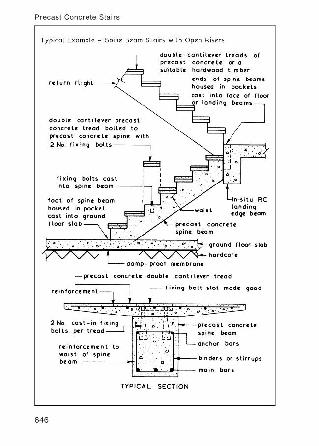
646
Precast Concrete Stairs
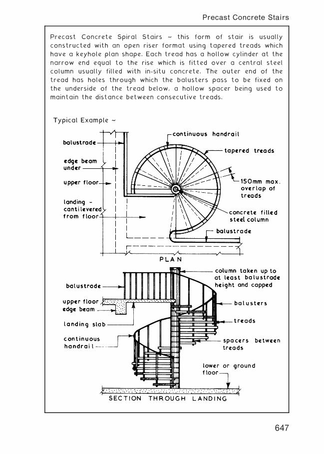
Precast Concrete Spiral Stairs ~ this form of stair is usually
constructed with an open riser format using tapered treads which
have a keyhole plan shape. Each tread has a hollow cylinder at the
narrow end equal to the rise which is fitted over a central steel
column usually filled with in-situ concrete. The outer end of the
tread has holes through which the balusters pass to be fixed on
the underside of the tread below, a hollow spacer being used to
maintain the distance between consecutive treads.
647
Precast Concrete Stairs
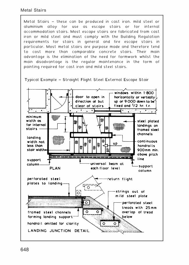
Metal Stairs ~ these can be produced in cast iron, mild steel or
aluminium alloy for use as escape stairs or for internal
accommodation stairs. Most escape stairs are fabricated from cast
iron or mild steel and must comply with the Building Regulation
requirements for stairs in general and fire escape stairs in
particular. Most metal stairs are purpose made and therefore tend
to cost more than comparable concrete stairs. Their main
advantage is the elimination of the need for formwork whilst the
main disadvantage is the regular maintenance in the form of
painting required for cast iron and mild steel stairs.
648
Metal Stairs
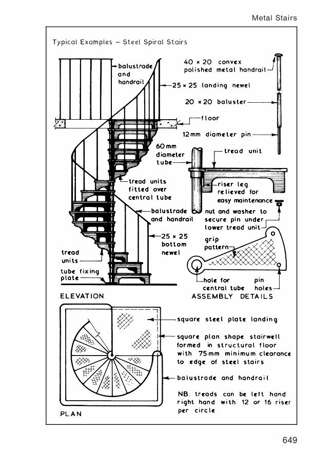
649
Metal Stairs
650
Metal Stairs
Balustrades and Handrails ~ these must comply in all respects with
the requirements given in Part K of the Building Regulations and in
the context of escape stairs are constructed of a non†combustible
material with a handrail shaped to give a comfortable hand grip.
The handrail may be covered or capped with a combustible
material such as timber or plastic. Most balustrades are designed
to be fixed after the stairs have been cast or installed by housing
the balusters in a preformed pocket or by direct surface fixing.
651
Balustrades and Handrails
Institutional and Assembly Stairs ~ Serving a place where a
substantial number of people will gather.
minimum going, 280 mm (mayreduce to 250 mm if the building floor area <100 m2), maximum, 340 mm
The maximum pitch for gangwayswith seated spectators in assemblybuildings is 35ƒ.
rise 135to 180 mm
Other stairs ~ All other buildings.
minimum going, 250 mmmaximum, 320 mm
rise 150to 190 mm
Common to both functionalgroups: twice the rise plusthe going, 550 to 700 mm.
Alternative guidance: BS 5395-1: Stairs, ladders and walkways. Code ofpractice for the design, construction and maintenance of straight stairsand winders.
The rise and going in both situations may be subject to the requirementsof Approved Document M: Access to and use of buildings. AD M will takepriority and the following will apply:
Going (external steps) ~ 280mm minimum (300 mm min. preferred).Going (stairs) ~ 250mm minimum.Rise ~ 170 mm maximum.
Other AD M requirements for stairs:
Avoid tapered treads.Width at least 1200mm between walls, strings or upstands.Landing top and bottom, minimum length not less than stair width.Handrails both sides; circular or oval preferred as shown on next page.Door openings onto landings to be avoided.Full risers, no gaps.Nosings with prominent colour 55 mm wide on tread and riser.Nosing projections avoided, maximum of 25 mm if necessary.Maximum 12 risers; exceptionally in certain small premises 16.Non-slip surface to treads and landing.
652
Public and General Use Stairs
Measurement of the going (AD K) ~
< 1 m
50 mm minimum treadwidth at newel
going measured atcentre of tread,minimum for privatestairs 220 mm, otherapplications 250 mm
=
=
For stair widths greater than 1 m, the going is measured at 270 mm
from each side of the stair.
Additional requirements:
Going of tapered treads not less than the going of parallel treads
in the same stair.
Curved landing lengths measured on the stair centre line.
Twice the rise plus the going, 550 to 700 mm.
Uniform going for consecutive tapered treads.
Other going and rise limitations as shown on the previous page.
Alternative guidance that is acceptable to the requirements of
Approved Document K is published in BS 5395-2: Stairs, ladders and
walkways. Code of practice for the design of helical and spiral
stairs.
Preferred handrail profile (AD M) ~
60 to 75 mm40 to 45 mm
diameter 50 mm
30 mmdiameter
Oval
Round
50 mm
653
Spiral Stairs and Tapered Treads
Functions ~ the main functions of any door are to:
1. Provide a means of access and egress.
2. Maintain continuity of wall function when closed.
3. Provide a degree of privacy and security.
Choice of door type can be determined by:†
1. Position † whether internal or external.
2. Properties required † fire resistant, glazed to provide for
borrowed light or vision through, etc.
3. Appearance † flush or panelled, painted or polished, etc.
Door Schedules ~ these can be prepared in the same manner and
for the same purpose as that given for windows on page 359.
Internal Doors ~ these are usually lightweight and can be fixed to
a lining, if heavy doors are specified these can be hung to frames in
a similar manner to external doors. An alternative method is to
use door sets which are usually storey height and supplied with
prehung doors.
654
Doors and Door Linings
Internal Doors ~ these are similar in construction to the external
doors but are usually thinner and therefore lighter in weight.
655
Internal Doors
Internal Door Frames and linings ~ these are similar in construction
to external door frames but usually have planted door stops and
do not have a sill. The frames are sized to be built in conjunction
with various partition thicknesses and surface finishes. Linings with
planted stops ae usually employed for lightweight domestic doors.
Ref. BS 4787: Internal and external wood doorsets, door leaves
and frames. Specification for dimensional requirements.
656
Internal Door Frames
Doorsets ~ these are factory produced fully assembled prehung
doors which are supplied complete with frame, architraves and
ironmongery except for door furniture. The doors may be hung to
the frames using pin butts for easy door removal. Prehung door
sets are available in standard and storey height versions and are
suitable for all internal door applications with normal wall and
partition thicknesses.
657
Doorsets
Fire doorset ~ a ``complete unit consisting of a door frame and a
door leaf or leaves, supplied with all essential parts from a single
source''. The difference between a doorset and a fire doorset is the
latter is endorsed with a fire certificate for the complete unit.
When supplied as a collection of parts for site assembly, this is
known as a door kit.
Fire door assembly ~ a ``complete assembly as installed, including
door frame and one or more leaves, together with its essential
hardware [ironmongery] supplied from separate sources''. Provided
the components to an assembly satisfy the Building Regulations †
Approved Document B, fire safety requirements and standards for
certification and compatibility, then a fire door assembly is an
acceptable alternative to a doorset.
Fire doorsets are usually more expensive than fire door assemblies,
but assemblies permit more flexibility in choice of components. Site
fixing time will be longer for assemblies.
(Quotes from BS EN 12519: Windows and pedestrian doors.
Terminology.)
Fire door ~ a fire door is not just the door leaf. A fire door
includes the frame, ironmongery, glazing, intumescent core and
smoke seal. To comply with European market requirements,
ironmongery should be CE marked (see page 61). A fire door should
also be marked accordingly on the top or hinge side. The label
type shown below, reproduced with kind permission of the British
Woodworking Federation is acceptable.
Company'sName
Company's OwnTelephone no.
CERTIFIRECertificate no.
Unique number = Full traceability
Sequential no.
658
Fire Doorsets and Fire Door Assemblies
30 Minute Flush Fire Doors ~ these are usually based on the
recommendations given in BS 8214. A wide variety of door
constructions are available from various manufacturers but they
all have to be fitted to a similar frame for testing as a doorset or
assembly, including ironmongery.
A door's resistance to fire is measured by:-
1. Insulation † resistance to thermal transmittance, see BS
476†20 & 22: Fire tests on building materials
and structures.
2. Integrity † resistance in minutes to the penetration of flame
and hot gases under simulated fire conditions.
659
30 Minute Flush Fire Doors
60 Minute Flush Fire Door ~ like the 30 minute flush fire door
shown on page 659 these doors are based on the recommendations
given in BS 8214 which covers both door and frame. A wide variety
of fire resistant door constructions are available from various
manufacturers with most classified as having both insulation and
integrity ratings of 60 minutes.
660
60 Minute Flush Fire Doors
Fire and Smoke Resistance ~ Doors can be assessed for both
integrity and smoke resistance. They are coded accordingly, for
example FD30 or FD30s. FD indicates a fire door and 30 the
integrity time in minutes. The letter `s' denotes that the door or
frame contains a facility to resist the passage of smoke.
Manufacturers produce doors of standard ratings † 30, 60 and
90 minutes, with higher ratings available to order. A colour coded
plug inserted in the door edge corresponds to the fire rating. See
BS 8214, Table 1 for details.
The intumescent core may be fitted to the door edge or the frame.
In practice, most joinery manufacturers leave a recess in the frame
where the seal is secured with rubber based or PVA adhesive. At
temperatures of about 150�C, the core expands to create a seal
around the door edge. This remains throughout the fire resistance
period whilst the door can still be opened for escape and access
purposes. The smoke seal will also function as an effective draught
seal.
Further references:
BS EN 1634-1: Fire resistance tests for door and shutter assemblies.
Fire doors and shutters.
BS EN 13501: Fire classification of construction products and
building elements.
661
Fire Resisting Doors
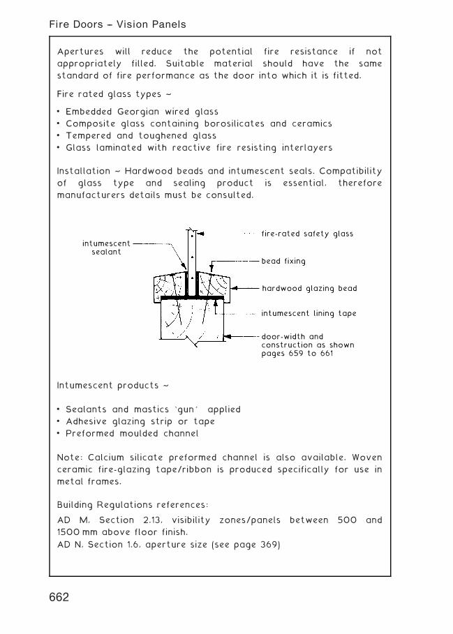
Apertures will reduce the potential fire resistance if not
appropriately filled. Suitable material should have the same
standard of fire performance as the door into which it is fitted.
Fire rated glass types ~
• Embedded Georgian wired glass
• Composite glass containing borosilicates and ceramics
• Tempered and toughened glass
• Glass laminated with reactive fire resisting interlayers
Installation ~ Hardwood beads and intumescent seals. Compatibility
of glass type and sealing product is essential, therefore
manufacturers details must be consulted.
intumescentsealant
fire-rated safety glass
bead fixing
intumescent lining tape
hardwood glazing bead
door-width andconstruction as shownpages 659 to 661
Intumescent products ~
• Sealants and mastics `gun' applied
• Adhesive glazing strip or tape
• Preformed moulded channel
Note: Calcium silicate preformed channel is also available. Woven
ceramic fire-glazing tape/ribbon is produced specifically for use in
metal frames.
Building Regulations references:
AD M, Section 2.13, visibility zones/panels between 500 and
1500 mm above floor finish.
AD N, Section 1.6, aperture size (see page 369)
662
Fire Doors -- Vision Panels
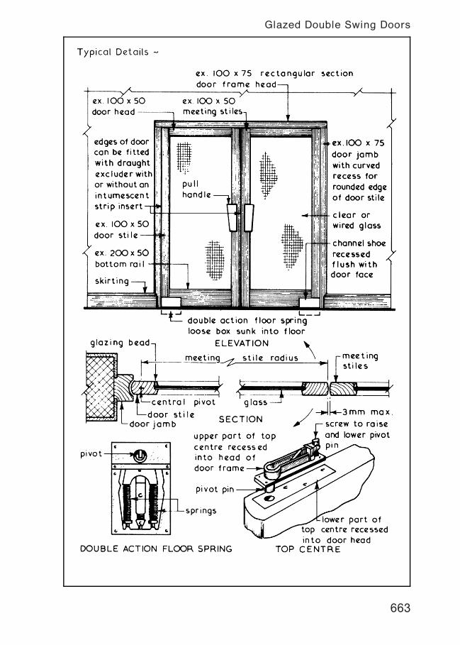
663
Glazed Double Swing Doors
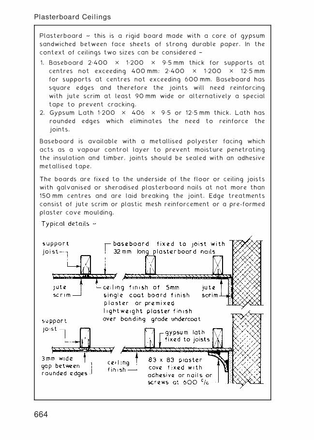
Plasterboard ~ this is a rigid board made with a core of gypsum
sandwiched between face sheets of strong durable paper. In the
context of ceilings two sizes can be considered †
1. Baseboard 2„400 � 1„200 � 9„5 mm thick for supports at
centres not exceeding 400 mm; 2„400 � 1„200 � 12„5 mm
for supports at centres not exceeding 600 mm. Baseboard has
square edges and therefore the joints will need reinforcing
with jute scrim at least 90 mm wide or alternatively a special
tape to prevent cracking.
2. Gypsum Lath 1„200 � 406 � 9„5 or 12„5 mm thick. Lath has
rounded edges which eliminates the need to reinforce the
joints.
Baseboard is available with a metallised polyester facing which
acts as a vapour control layer to prevent moisture penetrating
the insulation and timber, joints should be sealed with an adhesive
metallised tape.
The boards are fixed to the underside of the floor or ceiling joists
with galvanised or sheradised plasterboard nails at not more than
150 mm centres and are laid breaking the joint. Edge treatments
consist of jute scrim or plastic mesh reinforcement or a pre-formed
plaster cove moulding.
664
Plasterboard Ceilings
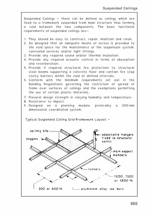
Suspended Ceilings ~ these can be defined as ceilings which are
fixed to a framework suspended from main structure thus forming
a void between the two components. The basic functional
requirements of suspended ceilings are:†
1. They should be easy to construct, repair, maintain and clean.
2. So designed that an adequate means of access is provided to
the void space for the maintenance of the suspension system,
concealed services and/or light fittings.
3. Provide any required sound and/or thermal insulation.
4. Provide any required acoustic control in terms of absorption
and reverberation.
5. Provide if required structural fire protection to structural
steel beams supporting a concrete floor and contain fire stop
cavity barriers within the void at defined intervals.
6. Conform with the minimum requirements set out in the
Building Regulations governing the restriction of spread of
flame over surfaces of ceilings and the exemptions permitting
the use of certain plastic materials.
7. Flexural design strength in varying humidity and temperature.
8. Resistance to impact.
9. Designed on a planning module, preferably a 300 mm
dimensional coordinated system.
665
Suspended Ceilings
Classification of Suspended Ceiling ~ there is no standard method
of classification since some are classified by their function such as
illuminated and acoustic suspended ceilings, others are classified by
the materials used and classification by method of construction
is also very popular. The latter method is simple since most
suspended ceiling types can be placed in one of three groups:-
1. Jointless suspended ceilings.
2. Panelled suspended ceilings † see page 667.
3. Decorative and open suspended ceilings † see page 668.
Jointless Suspended Ceilings ~ these forms of suspended ceilings
provide a continuous and jointless surface with the internal
appearance of a conventional ceiling. They may be selected to
fulfil fire resistance requirements or to provide a robust form of
suspended ceiling. The two common ways of construction are a
plasterboard or expanded metal lathing soffit with hand applied
plaster finish or a sprayed applied rendering with a cement base.
See also: BS EN 13964: Suspended ceilings. Requirements and test
methods.
666
Suspended Ceilings
Panelled Suspended Ceilings ~ these are the most popular form of
suspended ceiling consisting of a suspended grid framework to
which the ceiling covering is attached. The covering can be of a
tile, tray, board or strip format in a wide variety of materials with
an exposed or concealed supporting framework. Services such as
luminaries can usually be incorporated within the system. Generally
panelled systems are easy to assemble and install using a water
level or laser beam for initial and final levelling. Provision for
maintenance access can be easily incorporated into most systems
and layouts.
667
Suspended Ceilings
Decorative and Open Suspended Ceilings ~ these ceilings usually
consist of an openwork grid or suspended shapes onto which the
lights fixed at, above or below ceiling level can be trained thus
creating a decorative and illuminated effect. Many of these ceilings
are purpose designed and built as opposed to the proprietary
systems associated with jointless and panelled suspended ceilings.
668
Suspended Ceilings
Functions ~ the main functions of paint are to provide:†
1. An economic method of surface protection to building materials
and components.
2. An economic method of surface decoration to building materials
and components.
Composition ~ the actual composition of any paint can be complex
but the basic components are:†
1. Binder ~ this is the liquid vehicle or medium which dries to
form the surface film and can be composed of linseed oil,
drying oils, synthetic resins and water. The first function of a
paint medium is to provide a means of spreading the paint
over the surface and at the same time acting as a binder to
the pigment.
2. Pigment ~ this provides the body, colour, durability and
corrosion protection properties of the paint. White lead
pigments are very durable and moisture resistant but are
poisonous and their use is generally restricted to priming and
undercoating paints. If a paint contains a lead pigment the
fact must be stated on the container. The general pigment
used in paint is titanium dioxide which is not poisonous and
gives good obliteration of the undercoats.
3. Solvents and Thinners ~ these are materials which can be
added to a paint to alter its viscosity.
Paint Types † there is a wide range available but for most general
uses the following can be considered:†
1. Oil Based paints † these are available in priming, undercoat
and finishing grades. The latter can be obtained in a wide
range of colours and finishes such as matt, semi†matt,
eggshell, satin, gloss and enamel. Polyurethane paints have a
good hardness and resistance to water and cleaning. Oil
based paints are suitable for most applications if used in
conjunction with correct primer and undercoat.
2. Water Based Paints † most of these are called emulsion
paints the various finishes available being obtained by adding
to the water medium additives such as alkyd resin & polyvinyl
acetate (PVA). Finishes include matt, eggshell, semi-gloss and
gloss. Emulsion paints are easily applied, quick drying and can
be obtained with a washable finish and are suitable for most
applications.
669
Paints and Painting
Supply ~ paint is usually supplied in metal containers ranging from
250 millilitres to 5 litres capacity to the colour ranges
recommended in BS 381C (colours for specific purposes) and BS
4800 (paint colours for building purposes).
Application ~ paint can be applied to almost any surface providing
the surface preparation and sequence of paint coats are suitable.
The manufacturers specification and/or the recommendations of
BS 6150 (painting of buildings) should be followed. Preparation of
the surface to receive the paint is of the utmost importance since
poor preparation is one of the chief causes of paint failure. The
preperation consists basically of removing all dirt, grease, dust and
ensuring that the surface will provide an adequate key for the
paint which is to be applied. In new work the basic build-up of paint
coats consists of:-
1. Priming Coats † these are used on unpainted surfaces to obtain
the necessary adhesion and to inhibit corrosion of ferrous
metals. New timber should have the knots treated with a
solution of shellac or other alcohol based resin called knotting
prior to the application of the primer.
2. Undercoats † these are used on top of the primer after any
defects have been made good with a suitable stopper or filler.
The primary function of an undercoat is to give the opacity and
build†up necessary for the application of the finishing coat(s).
3. Finish † applied directly over the undercoating in one or more
coats to impart the required colour and finish.
Paint can applied by:-
1. Brush † the correct type, size and quality of brush such as
those recommended in BS 2992 (painters and decorators
brushes) needs to be selected and used. To achieve a first
class finish by means of brush application requires a high
degree of skill.
2. Spray † as with brush application a high degree of skill is
required to achieve a good finish. Generally compressed air
sprays or airless sprays are used for building works.
3. Roller † simple and inexpensive method of quickly and cleanly
applying a wide range of paints to flat and textured surfaces.
Roller heads vary in size from 50 to 450 mm wide with
various covers such as sheepskin, synthetic pile fibres, mohair
and foamed polystyrene. All paint applicators must be
thoroughly cleaned after use.
670
Paints and Painting
Painting ~ the main objectives of applying coats of paint to a
surface are preservation, protection and decoration to give a
finish which is easy to clean and maintain. To achieve these
objectives the surface preparation and paint application must be
adequate. The preparation of new and previously painted surfaces
should ensure that prior to painting the surface is smooth, clean,
dry and stable.
Basic Surface Preparation Techniques ~
Timber † to ensure a good adhesion of the paint film all timber
should have a moisture content of less than 18%. The timber
surface should be prepared using an abrasive paper to produce a
smooth surface brushed and wiped free of dust and any grease
removed with a suitable spirit. Careful treatment of knots is
essential either by sealing with two coats of knotting or in
extreme cases cutting out the knot and replacing with sound
timber. The stopping and filling of cracks and fixing holes with
putty or an appropriate filler should be carried out after the
application of the priming coat. Each coat of paint must be
allowed to dry hard and be rubbed down with a fine abrasive paper
before applying the next coat. On previously painted surfaces if
the paint is in a reasonable condition the surface will only require
cleaning and rubbing down before repainting, when the paint is in a
poor condition it will be necessary to remove completely the
layers of paint and then prepare the surface as described above
for new timber.
Building Boards † most of these boards require no special
preparation except for the application of a sealer as specified by
the manufacturer.
Iron and Steel † good preparation is the key to painting iron and
steel successfully and this will include removing all rust, mill scale,
oil, grease and wax. This can be achieved by wire brushing, using
mechanical means such as shot blasting, flame cleaning and
chemical processes and any of these processes are often carried
out in the steel fabrication works prior to shop applied priming.
Plaster † the essential requirement of the preparation is to ensure
that the plaster surface is perfectly dry, smooth and free of
defects before applying any coats of paint especially when using
gloss paints. Plaster which contains lime can be alkaline and such
surfaces should be treated with an alkali resistant primer when the
surface is dry before applying the final coats of paint.
671
Painting---Preparation
Paint Defects ~ these may be due to poor or incorrect preparation
of the surface, poor application of the paint and/or chemical
reactions. The general remedy is to remove all the affected paint
and carry out the correct preparation of the surface before
applying in the correct manner new coats of paint. Most paint
defects are visual and therefore an accurate diagnosis of the cause
must be established before any remedial treatment is undertaken.
Typical Paint Defects ~
1. Bleeding † staining and disruption of the paint surface by
chemical action, usually caused by applying an incorrect paint
over another. Remedy is to remove affected paint surface and
repaint with correct type of overcoat paint.
2. Blistering † usually caused by poor presentation allowing
resin or moisture to be entrapped, the subsequent expansion
causing the defect. Remedy is to remove all the coats of
paint and ensure that the surface is dry before repainting.
3. Blooming † mistiness usually on high gloss or varnished
surfaces due to the presence of moisture during application.
It can be avoided by not painting under these conditions.
Remedy is to remove affected paint and repaint.
4. Chalking † powdering of the paint surface due to natural
ageing or the use of poor quality paint. Remedy is to remove
paint if necessary, prepare surface and repaint.
5. Cracking and Crazing † usually due to unequal elasticity of
successive coats of paint. Remedy is to remove affected paint
and repaint with compatible coats of paint.
6. Flaking and Peeling † can be due to poor adhesion, presence
of moisture, painting over unclean areas or poor preparation.
Remedy is to remove defective paint, prepare surface and
repaint.
7. Grinning † due to poor opacity of paint film allowing paint
coat below or background to show through, could be the
result of poor application; incorrect thinning or the use of
the wrong colour. Remedy is to apply further coats of paint
to obtain a satisfactory surface.
8. Saponification † formation of soap from alkali present in or
on surface painted. The paint is ultimately destroyed and a
brown liquid appears on the surface. Remedy is to remove
the paint films and seal the alkaline surface before repainting.
672
Painting---Defects
Joinery Production ~ this can vary from the flow production where
one product such as flush doors is being made usually with the aid
of purpose designed and built machines, to batch production where
a limited number of similar items are being made with the aid of
conventional woodworking machines. Purpose made joinery is very
often largely hand made with a limited use of machines and is
considered when special and/or high class joinery components are
required.
Woodworking Machines ~ except for the portable electric tools
such as drills, routers, jigsaws and sanders most woodworking
machines need to be fixed to a solid base and connected to an
extractor system to extract and collect the sawdust and chippings
produced by the machines.
Saws † basically three formats are available, namely the circular,
cross cut and band saws. Circular are general purpose saws and
usually have tungsten carbide tipped teeth with feed rates of up to
60„000 per minute. Cross cut saws usually have a long bench to
support the timber, the saw being mounted on a radial arm
enabling the circular saw to be drawn across the timber to be cut.
Band saws consist of an endless thin band or blade with saw teeth
and a table on which to support the timber and are generally used
for curved work.
Planers † most of these machines are combined planers and
thicknessers, the timber being passed over the table surface for
planning and the table or bed for thicknessing. The planer has a
guide fence which can be tilted for angle planning and usually the
rear bed can be lowered for rebating operations. The same
rotating cutter block is used for all operations. Planing speeds are
dependent upon the operator since it is a hand fed operation
whereas thicknessing is mechanically fed with a feed speed range of
6„000 to 20„000 per minute. Maximum planing depth is usually
10 mm per passing.
Morticing Machines † these are used to cut mortices up to 25 mm
wide and can be either a chisel or chain morticer. The former
consists of a hollow chisel containing a bit or auger whereas the
latter has an endless chain cutter.
Tenoning Machines † these machines with their rotary cutter
blocks can be set to form tenon and scribe. In most cases they can
also be set for trenching, grooving and cross cutting.
Spindle Moulder † this machine has a horizontally rotating cutter
block into which standard or purpose made cutters are fixed to
reproduce a moulding on timber passed across the cutter.
673
Joinery Production
Purpose Made Joinery ~ joinery items in the form of doors,
windows, stairs and cupboard fitments can be purchased as stock
items from manufacturers. There is also a need for purpose made
joinery to fulfil client/designer/user requirement to suit a specific
need, to fit into a non-standard space, as a specific decor
requirement or to complement a particular internal environment.
These purpose made joinery items can range from the simple to the
complex which require high degrees of workshop and site skills.
674
Joinery Production
675
Joinery Production
Joinery Timbers ~ both hardwoods and softwoods can be used for
joinery works. Softwoods can be selected for their stability,
durability and/or workability if the finish is to be paint but if it is
left in its natural colour with a sealing coat the grain texture and
appearance should be taken into consideration. Hardwoods are
usually left in their natural colour and treated with a protective
clear sealer or polish therefore texture, colour and grain pattern
are important when selecting hardwoods for high class joinery
work.
Typical Softwoods Suitable for Joinery Work ~
1. Douglas Fir † sometimes referred to as Columbian Pine or
Oregon Pine. It is available in long lengths and has a straight
grain. Colour is reddish brown to pink. Suitable for general
and high class joinery. Approximate density 530 kg/m3.
2. Redwood † also known as Scots Pine. Red Pine, Red Deal and
Yellow Deal. It is a widely used softwood for general joinery
work having good durability a straight grain and is reddish
brown to straw in colour. Approximate density 430 kg/m3.
3. European Spruce † similar to redwood but with a lower
durability. It is pale yellow to pinkish white in colour and is
used mainly for basic framing work and simple internal
joinery. Approximate density 650 kg/m3.
4. Sitka Spruce † originates from Alaska, Western Canada and
Northwest USA. The long, white strong fibres provide a timber
quality for use in board or plywood panels. Approximate
density 450 kg/m3.
5. Pitch Pine † durable softwood suitable for general joinery
work. It is light red to reddish yellow in colour and tends to
have large knots which in some cases can be used as a
decorative effect. Approximate density 650 kg/m3.
6. Parana Pine † moderately durable straight grained timber
available in a good range of sizes. Suitable for general
joinery work especially timber stairs. Light to dark brown in colour
with the occasional pink stripe. Approximate density 560 kg/m3.
7. Western Hemlock † durable softwood suitable for interior
joinery work such as panelling. Light yellow to reddish brown
in colour. Approximate density 500 kg/m3.
8. Western Red Cedar † originates from British Columbia and
Western USA. A straight grained timber suitable for flush doors
and panel work. Approximate density 380 kg/m3.
676
Joinery Production
Typical Hardwoods Suitable for Joinery Works ~
1. Beech † hard close grained timber with some silver grain in the
predominately reddish yellow to light brown colour. Suitable for
all internal joinery. Approximately density 700 kg/m3.
2. Iroko † hard durable hardwood with a figured grain and is
usually golden brown in colour. Suitable for all forms of
good class joinery. Approximate density 660 kg/m3.
3. Mahogany (African) † interlocking grained hardwood with good
durability. It has an attractive light brown to deep red colour
and is suitable for panelling and all high class joinery work.
Approximate density 560 kg/m3.
4. Mahogany (Honduras) † durable hardwood usually straight
grained but can have a mottled or swirl pattern. It is light red
to pale reddish brown in colour and is suitable for all good class
joinery work. Approximate density 530 kg/m3.
5. Mahogany (South American) † a well figured, stable and
durable hardwood with a deep red or brown colour which is
suitable for all high class joinery particularly where a high
polish is required. Approximate density 550 kg/m3.
6. Oak (English) † very durable hardwood with a wide variety of
grain patterns. It is usually a light yellow brown to a warm
brown in colour and is suitable for all forms of joinery but
should not be used in conjunction with ferrous metals due to
the risk of staining caused by an interaction of the two
materials. (The gallic acid in oak causes corrosion in ferrous
metals.) Approximate density 720 kg/m3.
7. Sapele † close texture timber of good durability, dark reddish
brown in colour with a varied grain pattern. It is suitable for
most internal joinery work especially where a polished finish
is required. Approximate density 640 kg/m3.
8. Teak † very strong and durable timber but hard to work. It
is light golden brown to dark golden yellow in colour which
darkens with age and is suitable for high class joinery work
and laboratory fittings. Approximate density 650 kg/m3.
9. Jarrah (Western Australia) † hard, dense, straight grained
timber. Dull red colour, suited to floor and stair construction
subjected to heavy wear. Approximate density 820 kg/m3.
677
Joinery Production
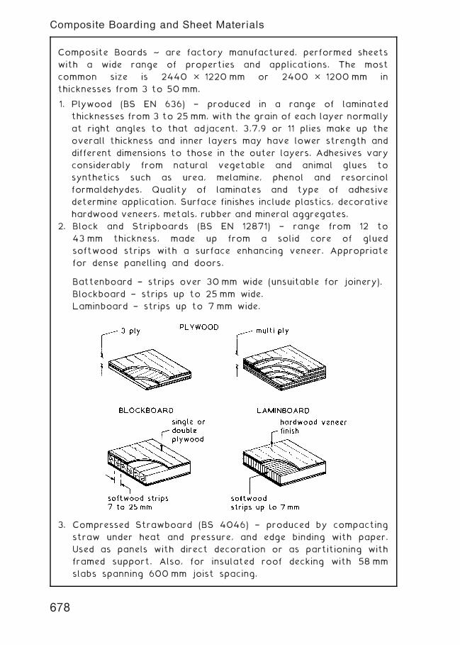
Composite Boards ~ are factory manufactured, performed sheets
with a wide range of properties and applications. The most
common size is 2440 � 1220 mm or 2400 � 1200 mm in
thicknesses from 3 to 50 mm.
1. Plywood (BS EN 636) † produced in a range of laminated
thicknesses from 3 to 25 mm, with the grain of each layer normally
at right angles to that adjacent. 3,7,9 or 11 plies make up the
overall thickness and inner layers may have lower strength and
different dimensions to those in the outer layers. Adhesives vary
considerably from natural vegetable and animal glues to
synthetics such as urea, melamine, phenol and resorcinol
formaldehydes. Quality of laminates and type of adhesive
determine application. Surface finishes include plastics, decorative
hardwood veneers, metals, rubber and mineral aggregates.
2. Block and Stripboards (BS EN 12871) † range from 12 to
43 mm thickness, made up from a solid core of glued
softwood strips with a surface enhancing veneer. Appropriate
for dense panelling and doors.
Battenboard † strips over 30mm wide (unsuitable for joinery).
Blockboard † strips up to 25 mm wide.
Laminboard † strips up to 7 mm wide.
3. Compressed Strawboard (BS 4046) † produced by compacting
straw under heat and pressure, and edge binding with paper.
Used as panels with direct decoration or as partitioning with
framed support. Also, for insulated roof decking with 58 mm
slabs spanning 600 mm joist spacing.
678
Composite Boarding and Sheet Materials
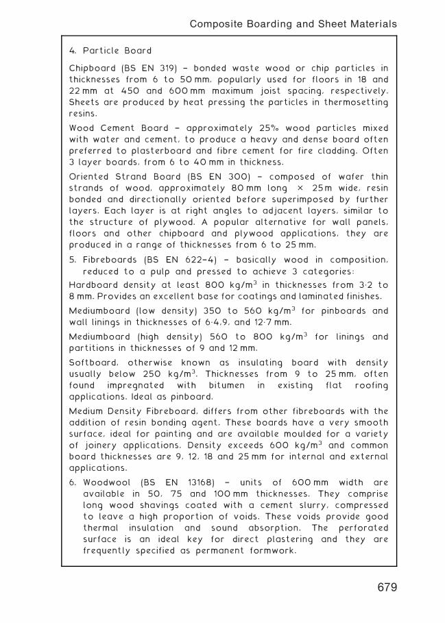
4. Particle Board
Chipboard (BS EN 319) † bonded waste wood or chip particles in
thicknesses from 6 to 50mm, popularly used for floors in 18 and
22 mm at 450 and 600mm maximum joist spacing, respectively.
Sheets are produced by heat pressing the particles in thermosetting
resins.
Wood Cement Board † approximately 25% wood particles mixed
with water and cement, to produce a heavy and dense board often
preferred to plasterboard and fibre cement for fire cladding. Often
3 layer boards, from 6 to 40 mm in thickness.
Oriented Strand Board (BS EN 300) † composed of wafer thin
strands of wood, approximately 80 mm long � 25m wide, resin
bonded and directionally oriented before superimposed by further
layers. Each layer is at right angles to adjacent layers, similar to
the structure of plywood. A popular alternative for wall panels,
floors and other chipboard and plywood applications, they are
produced in a range of thicknesses from 6 to 25 mm.
5. Fibreboards (BS EN 622†4) † basically wood in composition,
reduced to a pulp and pressed to achieve 3 categories:
Hardboard density at least 800 kg/m3 in thicknesses from 3„2 to
8 mm. Provides an excellent base for coatings and laminated finishes.
Mediumboard (low density) 350 to 560 kg/m3 for pinboards and
wall linings in thicknesses of 6„4,9, and 12„7 mm.
Mediumboard (high density) 560 to 800 kg/m3 for linings and
partitions in thicknesses of 9 and 12 mm.
Softboard, otherwise known as insulating board with density
usually below 250 kg/m3. Thicknesses from 9 to 25 mm, often
found impregnated with bitumen in existing flat roofing
applications. Ideal as pinboard.
Medium Density Fibreboard, differs from other fibreboards with the
addition of resin bonding agent. These boards have a very smooth
surface, ideal for painting and are available moulded for a variety
of joinery applications. Density exceeds 600 kg/m3 and common
board thicknesses are 9, 12, 18 and 25 mm for internal and external
applications.
6. Woodwool (BS EN 13168) † units of 600 mm width are
available in 50, 75 and 100 mm thicknesses. They comprise
long wood shavings coated with a cement slurry, compressed
to leave a high proportion of voids. These voids provide good
thermal insulation and sound absorption. The perforated
surface is an ideal key for direct plastering and they are
frequently specified as permanent formwork.
679
Composite Boarding and Sheet Materials
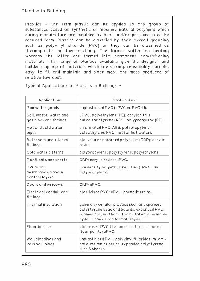
Plastics ~ the term plastic can be applied to any group of
substances based on synthetic or modified natural polymers which
during manufacture are moulded by heat and/or pressure into the
required form. Plastics can be classified by their overall grouping
such as polyvinyl chloride (PVC) or they can be classified as
thermoplastic or thermosetting. The former soften on heating
whereas the latter are formed into permanent non-softening
materials. The range of plastics available give the designer and
builder a group of materials which are strong, reasonably durable,
easy to fit and maintain and since most are mass produced of
relative low cost.
Typical Applications of Plastics in Buildings ~
Application Plastics Used
Rainwater goods unplasticised PVC (uPVC or PVC†U).
Soil, waste, water and
gas pipes and fittings
uPVC; polyethylene (PE); acrylonitrile
butadiene styrene (ABS), polypropylene (PP).
Hot and cold water
pipes
chlorinated PVC; ABS; polypropylene;
polyethylene; PVC (not for hot water).
Bathroom and kitchen
fittings
glass fibre reinforced polyester (GRP); acrylic
resins.
Cold water cisterns polypropylene; polystyrene; polyethylene.
Rooflights and sheets GRP; acrylic resins; uPVC.
DPC's and
membranes, vapour
control layers
low density polyethylene (LDPE); PVC film;
polypropylene.
Doors and windows GRP; uPVC.
Electrical conduit and
fittings
plasticised PVC; uPVC; phenolic resins.
Thermal insulation generally cellular plastics such as expanded
polystyrene bead and boards; expanded PVC;
foamed polyurethane; foamed phenol formalde-
hyde; foamed urea formaldehyde.
Floor finishes plasticised PVC tiles and sheets; resin based
floor paints; uPVC.
Wall claddings and
internal linings
unplasticised PVC; polyvinyl fluoride film lami-
nate; melamine resins; expanded polystyrene
tiles & sheets.
Plastics in Building
680
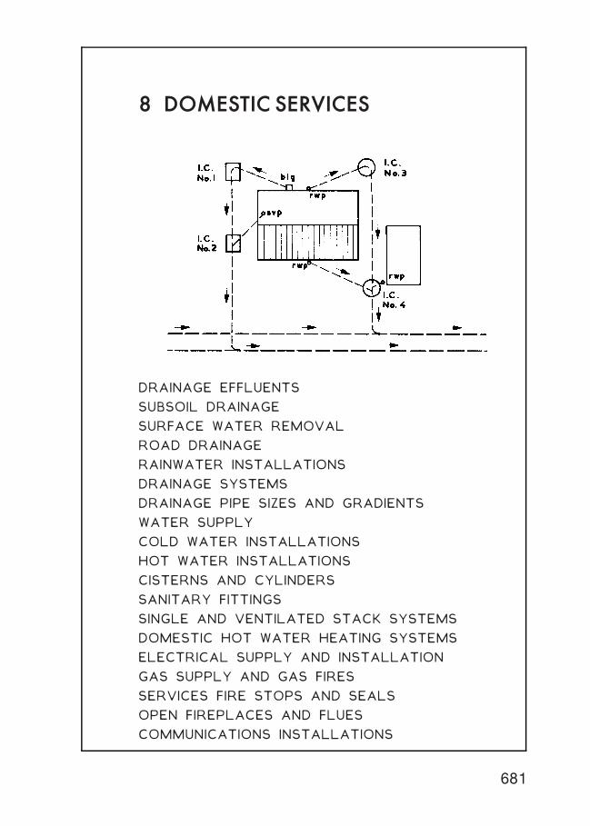
8 DOMESTIC SERVICES
DRAINAGE EFFLUENTS
SUBSOIL DRAINAGE
SURFACE WATER REMOVAL
ROAD DRAINAGE
RAINWATER INSTALLATIONS
DRAINAGE SYSTEMS
DRAINAGE PIPE SIZES AND GRADIENTS
WATER SUPPLY
COLD WATER INSTALLATIONS
HOT WATER INSTALLATIONS
CISTERNS AND CYLINDERS
SANITARY FITTINGS
SINGLE AND VENTILATED STACK SYSTEMS
DOMESTIC HOT WATER HEATING SYSTEMS
ELECTRICAL SUPPLY AND INSTALLATION
GAS SUPPLY AND GAS FIRES
SERVICES FIRE STOPS AND SEALS
OPEN FIREPLACES AND FLUES
COMMUNICATIONS INSTALLATIONS
681
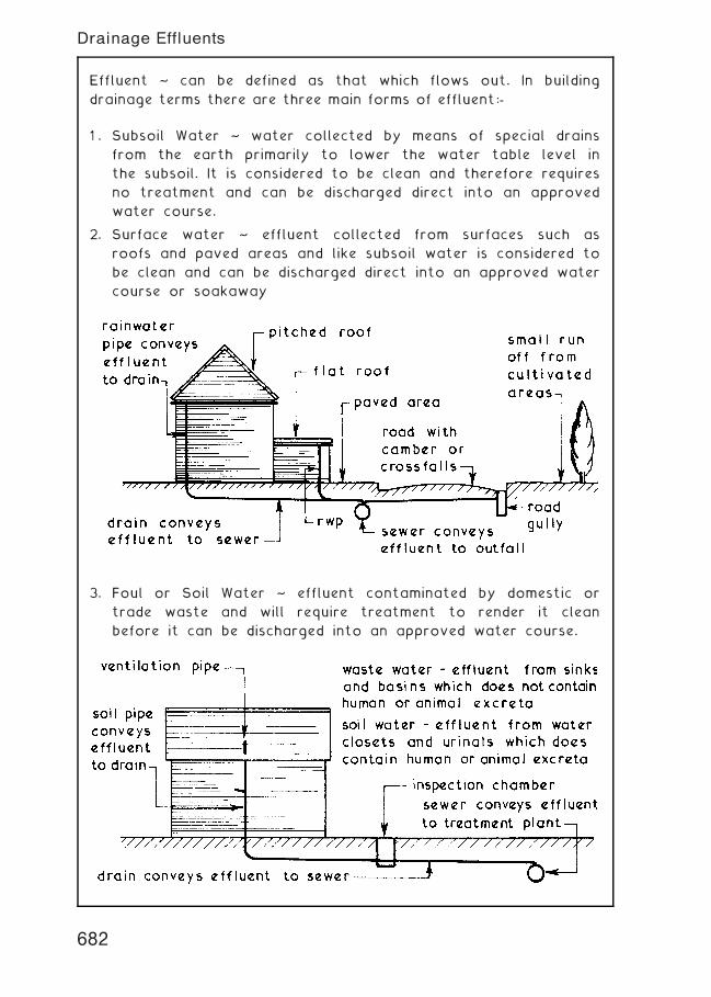
Effluent ~ can be defined as that which flows out. In building
drainage terms there are three main forms of effluent:-
1 . Subsoil Water ~ water collected by means of special drains
from the earth primarily to lower the water table level in
the subsoil. It is considered to be clean and therefore requires
no treatment and can be discharged direct into an approved
water course.
2. Surface water ~ effluent collected from surfaces such as
roofs and paved areas and like subsoil water is considered to
be clean and can be discharged direct into an approved water
course or soakaway
3. Foul or Soil Water ~ effluent contaminated by domestic or
trade waste and will require treatment to render it clean
before it can be discharged into an approved water course.
682
Drainage Effluents
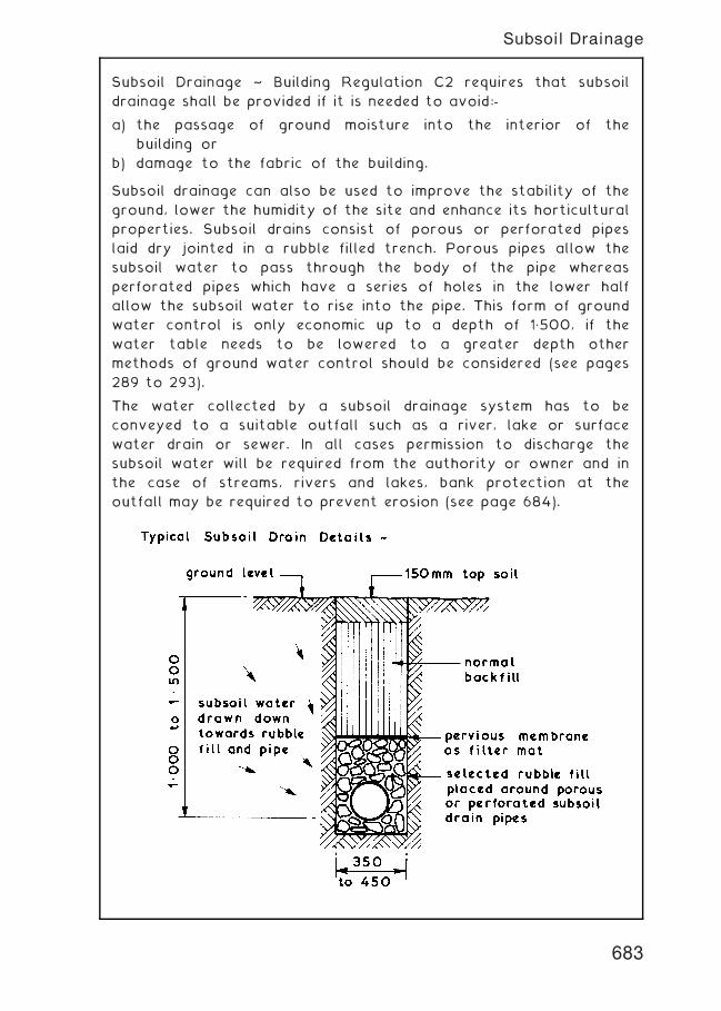
Subsoil Drainage ~ Building Regulation C2 requires that subsoil
drainage shall be provided if it is needed to avoid:-
a) the passage of ground moisture into the interior of the
building or
b) damage to the fabric of the building.
Subsoil drainage can also be used to improve the stability of the
ground, lower the humidity of the site and enhance its horticultural
properties. Subsoil drains consist of porous or perforated pipes
laid dry jointed in a rubble filled trench. Porous pipes allow the
subsoil water to pass through the body of the pipe whereas
perforated pipes which have a series of holes in the lower half
allow the subsoil water to rise into the pipe. This form of ground
water control is only economic up to a depth of 1„500, if the
water table needs to be lowered to a greater depth other
methods of ground water control should be considered (see pages
289 to 293).
The water collected by a subsoil drainage system has to be
conveyed to a suitable outfall such as a river, lake or surface
water drain or sewer. In all cases permission to discharge the
subsoil water will be required from the authority or owner and in
the case of streams, rivers and lakes, bank protection at the
outfall may be required to prevent erosion (see page 684).
683
Subsoil Drainage
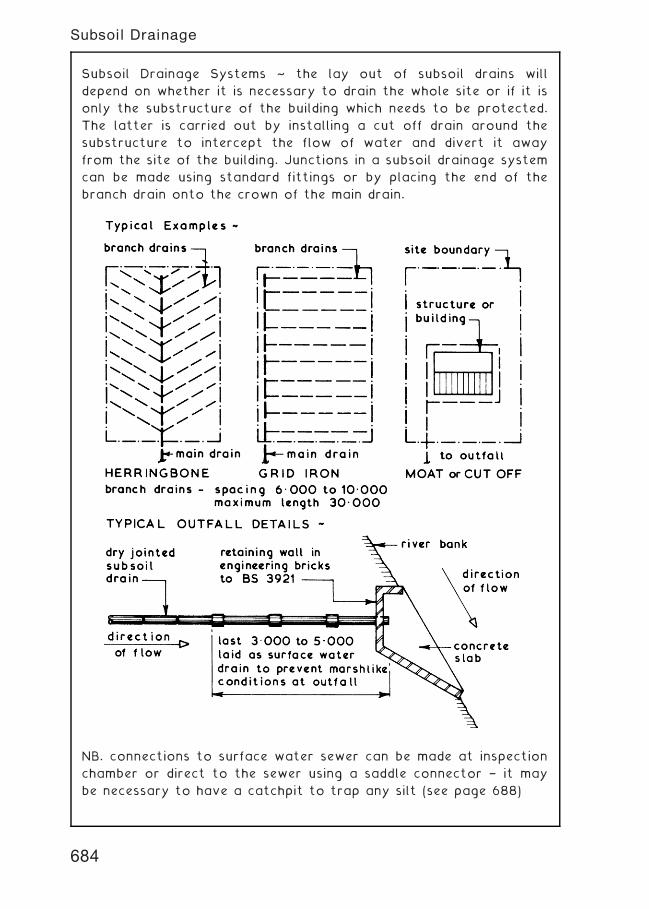
Subsoil Drainage Systems ~ the lay out of subsoil drains will
depend on whether it is necessary to drain the whole site or if it is
only the substructure of the building which needs to be protected.
The latter is carried out by installing a cut off drain around the
substructure to intercept the flow of water and divert it away
from the site of the building. Junctions in a subsoil drainage system
can be made using standard fittings or by placing the end of the
branch drain onto the crown of the main drain.
NB. connections to surface water sewer can be made at inspection
chamber or direct to the sewer using a saddle connector † it may
be necessary to have a catchpit to trap any silt (see page 688)
684
Subsoil Drainage
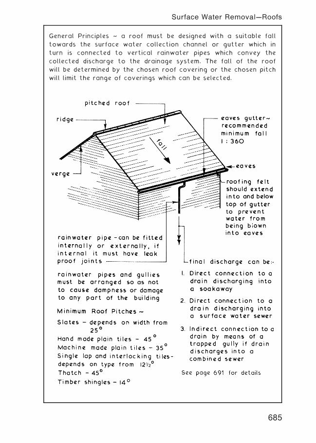
General Principles ~ a roof must be designed with a suitable fall
towards the surface water collection channel or gutter which in
turn is connected to vertical rainwater pipes which convey the
collected discharge to the drainage system. The fall of the roof
will be determined by the chosen roof covering or the chosen pitch
will limit the range of coverings which can be selected.
685
Surface Water Removal---Roofs
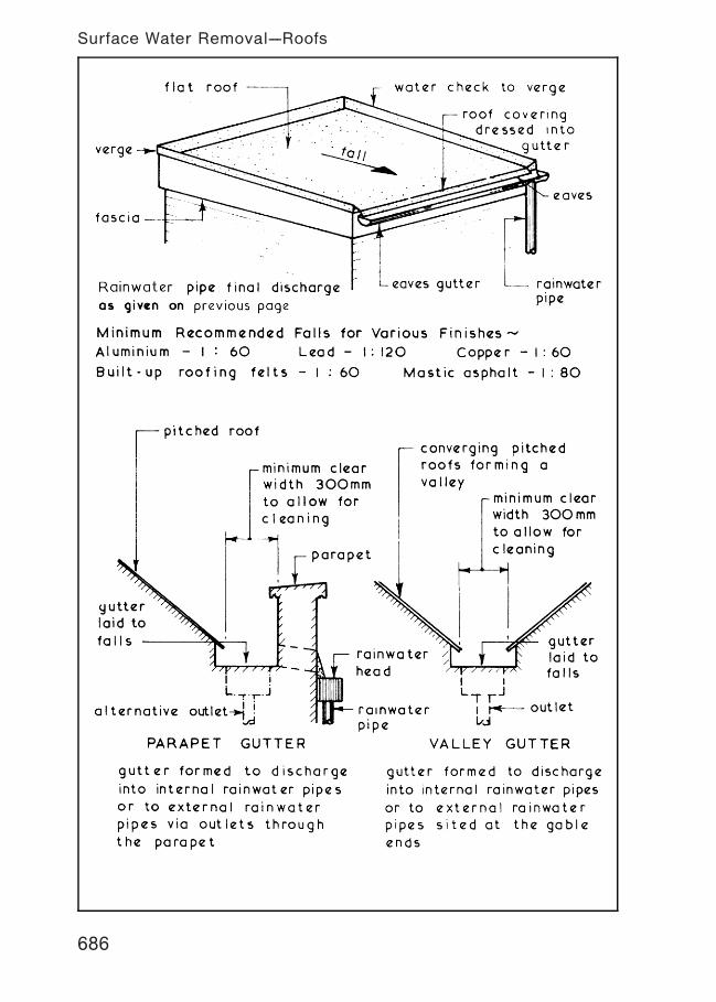
686
Surface Water Removal---Roofs
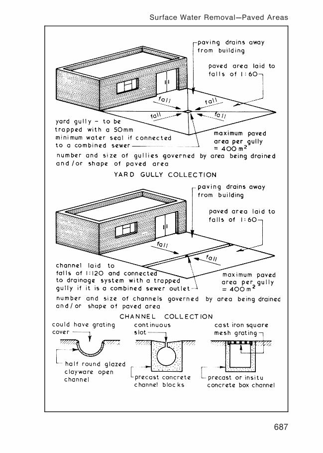
687
Surface Water Removal---Paved Areas
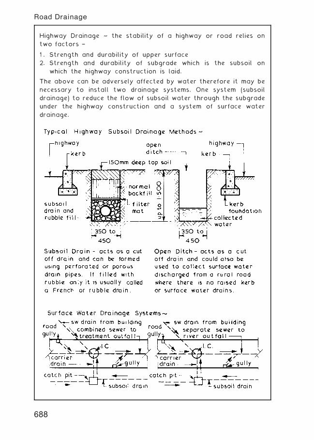
Highway Drainage ~ the stability of a highway or road relies on
two factors †
1 . Strength and durability of upper surface
2. Strength and durability of subgrade which is the subsoil on
which the highway construction is laid.
The above can be adversely affected by water therefore it may be
necessary to install two drainage systems. One system (subsoil
drainage) to reduce the flow of subsoil water through the subgrade
under the highway construction and a system of surface water
drainage.
688
Road Drainage
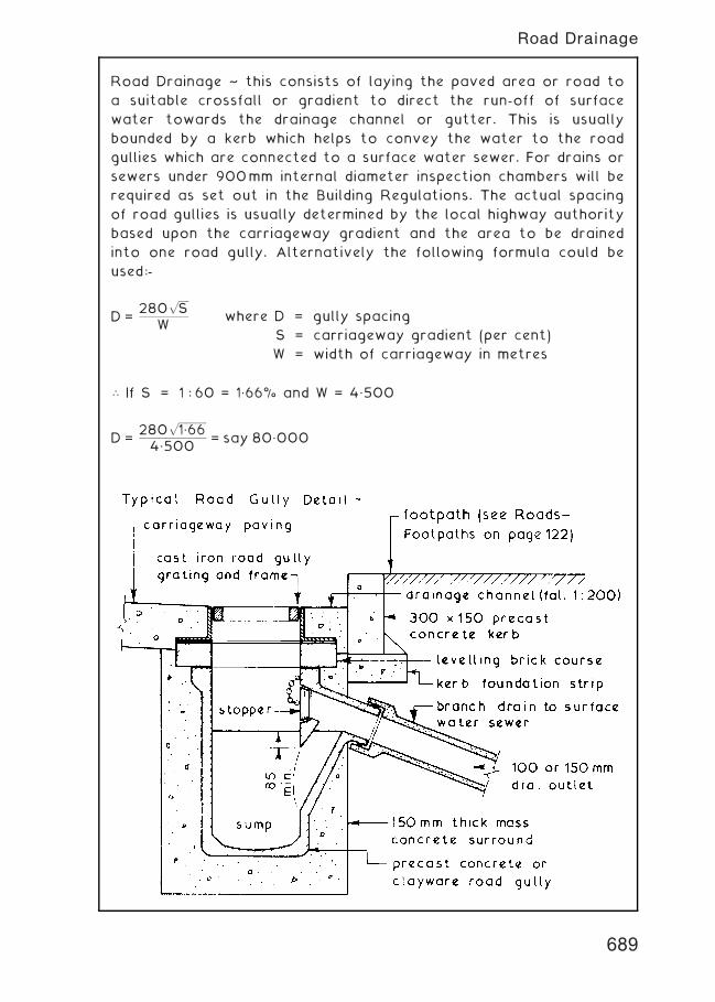
Road Drainage ~ this consists of laying the paved area or road to
a suitable crossfall or gradient to direct the run-off of surface
water towards the drainage channel or gutter. This is usually
bounded by a kerb which helps to convey the water to the road
gullies which are connected to a surface water sewer. For drains or
sewers under 900mm internal diameter inspection chambers will be
required as set out in the Building Regulations. The actual spacing
of road gullies is usually determined by the local highway authority
based upon the carriageway gradient and the area to be drained
into one road gully. Alternatively the following formula could be
used:-
D =280
ffiffiffiffiffi
Sp
Wwhere D = gully spacing
S = carriageway gradient (per cent)
W = width of carriageway in metres
\ If S = 1 : 60 = 1„66% and W = 4„500
D =280
ffiffiffiffiffiffiffiffiffiffiffiffiffi
1„66p
4„500= say 80„000
689
Road Drainage
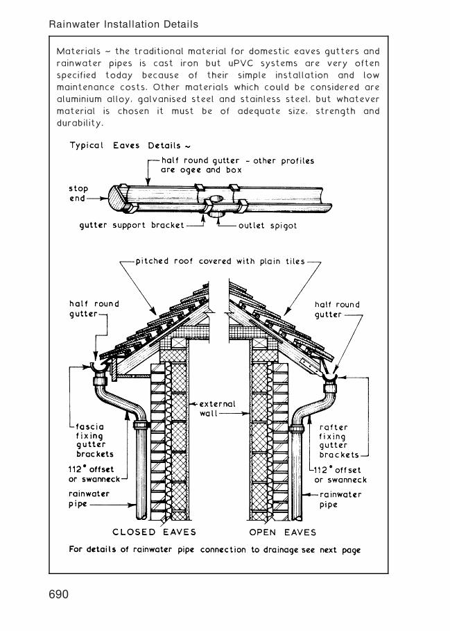
Materials ~ the traditional material for domestic eaves gutters and
rainwater pipes is cast iron but uPVC systems are very often
specified today because of their simple installation and low
maintenance costs. Other materials which could be considered are
aluminium alloy, galvanised steel and stainless steel, but whatever
material is chosen it must be of adequate size, strength and
durability.
690
Rainwater Installation Details
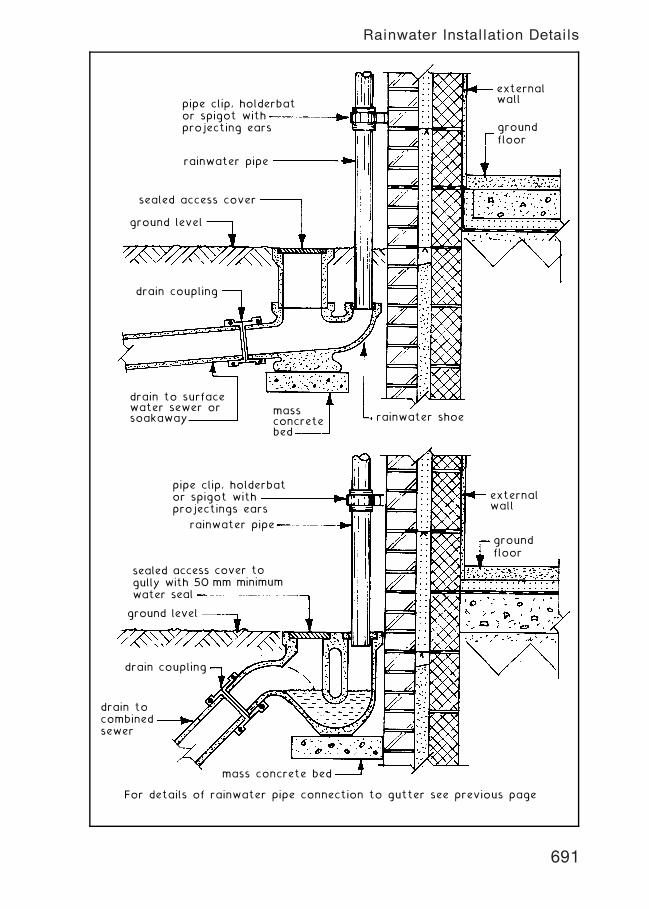
externalwallpipe clip, holderbat
or spigot withprojecting ears
rainwater pipe
rainwater shoe
sealed access cover
ground level
drain coupling
drain to surfacewater sewer orsoakaway
massconcretebed
groundfloor
externalwall
pipe clip, holderbator spigot withprojectings ears
rainwater pipe
drain coupling
sealed access cover togully with 50 mm minimumwater seal
drain tocombinedsewer
mass concrete bed
For details of rainwater pipe connection to gutter see previous page
groundfloor
ground level
691
Rainwater Installation Details
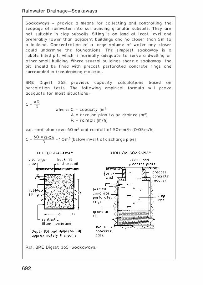
Soakaways ~ provide a means for collecting and controlling the
seapage of rainwater into surrounding granular subsoils. They are
not suitable in clay subsoils. Siting is on land at least level and
preferably lower than adjacent buildings and no closer than 5m to
a building. Concentration of a large volume of water any closer
could undermine the foundations. The simplest soakaway is a
rubble filled pit, which is normally adequate to serve a dwelling or
other small building. Where several buildings share a soakaway, the
pit should be lined with precast perforated concrete rings and
surrounded in free-draining material.
BRE Digest 365 provides capacity calculations based on
percolation tests. The following empirical formula will prove
adequate for most situations:-
C =AR3
where: C = capacity (m3)
A = area on plan to be drained (m2)
R = rainfall (m/h)
e.g. roof plan area 60m2 and rainfall of 50mm/h (0„05m/h)
C =60 � 0„05
3= 1„0m3 (below invert of discharge pipe)
Ref. BRE Digest 365: Soakaways.
692
Rainwater Drainage---Soakaways
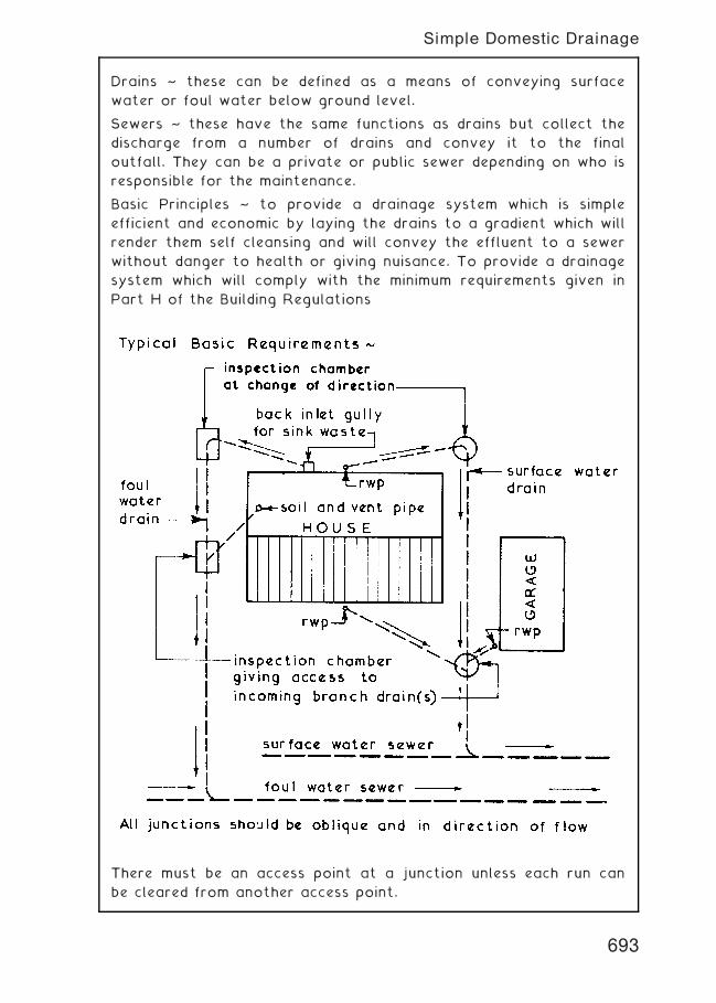
Drains ~ these can be defined as a means of conveying surface
water or foul water below ground level.
Sewers ~ these have the same functions as drains but collect the
discharge from a number of drains and convey it to the final
outfall. They can be a private or public sewer depending on who is
responsible for the maintenance.
Basic Principles ~ to provide a drainage system which is simple
efficient and economic by laying the drains to a gradient which will
render them self cleansing and will convey the effluent to a sewer
without danger to health or giving nuisance. To provide a drainage
system which will comply with the minimum requirements given in
Part H of the Building Regulations
There must be an access point at a junction unless each run can
be cleared from another access point.
693
Simple Domestic Drainage
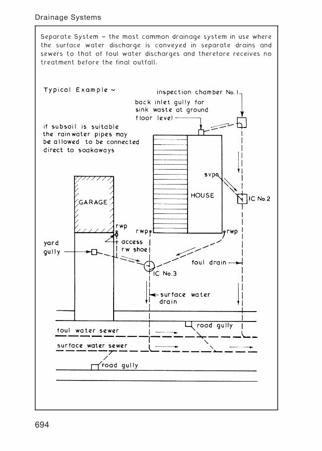
Separate System ~ the most common drainage system in use where
the surface water discharge is conveyed in separate drains and
sewers to that of foul water discharges and therefore receives no
treatment before the final outfall.
694
Drainage Systems
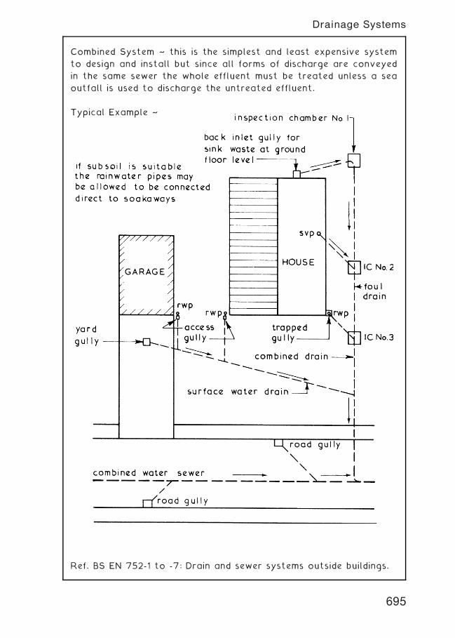
Combined System ~ this is the simplest and least expensive system
to design and install but since all forms of discharge are conveyed
in the same sewer the whole effluent must be treated unless a sea
outfall is used to discharge the untreated effluent.
Typical Example ~
Ref. BS EN 752-1 to -7: Drain and sewer systems outside buildings.
695
Drainage Systems
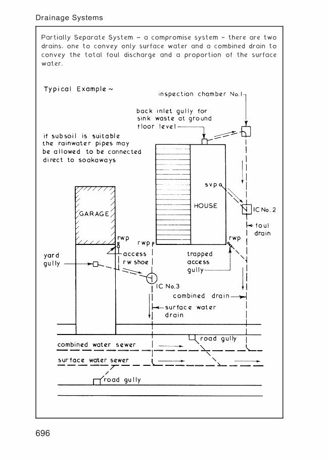
Partially Separate System ~ a compromise system † there are two
drains, one to convey only surface water and a combined drain to
convey the total foul discharge and a proportion of the surface
water.
696
Drainage Systems
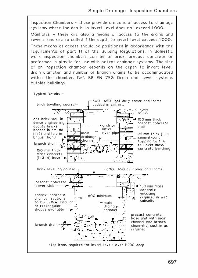
Inspection Chambers ~ these provide a means of access to drainage
systems where the depth to invert level does not exceed 1„000.
Manholes ~ these are also a means of access to the drains and
sewers, and are so called if the depth to invert level exceeds 1„000.
These means of access should be positioned in accordance with the
requirements of part H of the Building Regulations. In domestic
work inspection chambers can be of brick, precast concrete or
preformed in plastic for use with patent drainage systems. The size
of an inspection chamber depends on the depth to invert level,
drain diameter and number of branch drains to be accommodated
within the chamber. Ref. BS EN 752: Drain and sewer systems
outside buildings.
Typical Details ~
brick levelling course
one brick wall indense engineeringquality bricksbedded in cm. mt.(1 : 3) and laid inEnglish bond
branch drain
150 mm thickmass concrete(1 : 3 : 6) base
brick levelling course
precast concretecover slab
precast concretechamber sectionsto BS 5911- 4, circularor rectangular shapes available
precast concretebase unit with mainchannel and branchchannel(s) cast in asrequired
branch drain
step irons required for invert levels over 1„200 deep
600 × 450 light duty cover and framebedded in cm. mt.
600 × 450 c.i. cover and frame
600 minimum
1 : 6 fall
maindrainagechannel
100 mm thickprecast concreteslab
150 mm massconcreteencasingrequired in wetsubsoils
25 mm thick (1 : 1)cement/sandtopping to 1 : 6fall over massconcrete benching
maindrainagechannel
arch orlintelover pipe
697
Simple Drainage---Inspection Chambers
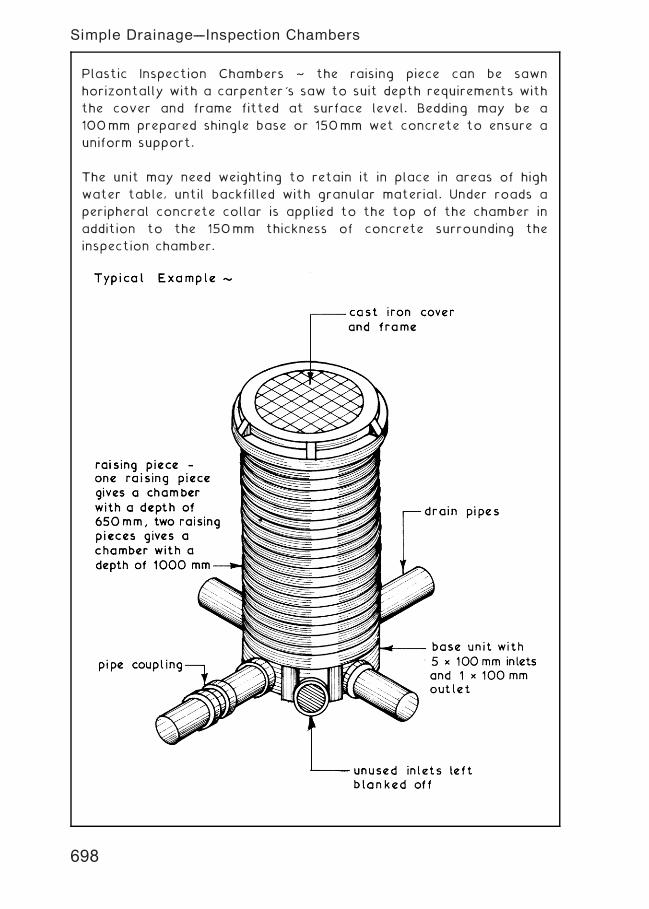
Plastic Inspection Chambers ~ the raising piece can be sawn
horizontally with a carpenter's saw to suit depth requirements with
the cover and frame fitted at surface level. Bedding may be a
100mm prepared shingle base or 150mm wet concrete to ensure a
uniform support.
The unit may need weighting to retain it in place in areas of high
water table, until backfilled with granular material. Under roads a
peripheral concrete collar is applied to the top of the chamber in
addition to the 150mm thickness of concrete surrounding the
inspection chamber.
698
Simple Drainage---Inspection Chambers
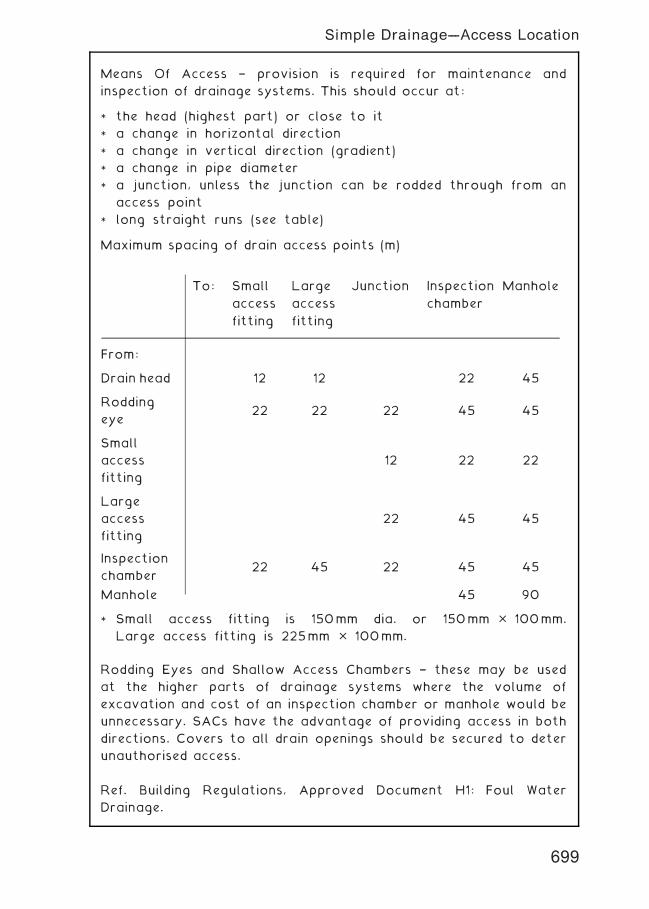
Means Of Access † provision is required for maintenance and
inspection of drainage systems. This should occur at:
* the head (highest part) or close to it
* a change in horizontal direction
* a change in vertical direction (gradient)
* a change in pipe diameter
* a junction, unless the junction can be rodded through from an
access point
* long straight runs (see table)
Maximum spacing of drain access points (m)
* Small access fitting is 150mm dia. or 150mm � 100mm.
Large access fitting is 225mm � 100mm.
Rodding Eyes and Shallow Access Chambers † these may be used
at the higher parts of drainage systems where the volume of
excavation and cost of an inspection chamber or manhole would be
unnecessary. SACs have the advantage of providing access in both
directions. Covers to all drain openings should be secured to deter
unauthorised access.
Ref. Building Regulations, Approved Document H1: Foul Water
Drainage.
To: Small
access
fitting
Large
access
fitting
Junction Inspection
chamber
Manhole
From:
Drain head 12 12 22 45
Rodding
eye22 22 22 45 45
Small
access
fitting
12 22 22
Large
access
fitting
22 45 45
Inspection
chamber22 45 22 45 45
Manhole 45 90
699
Simple Drainage---Access Location
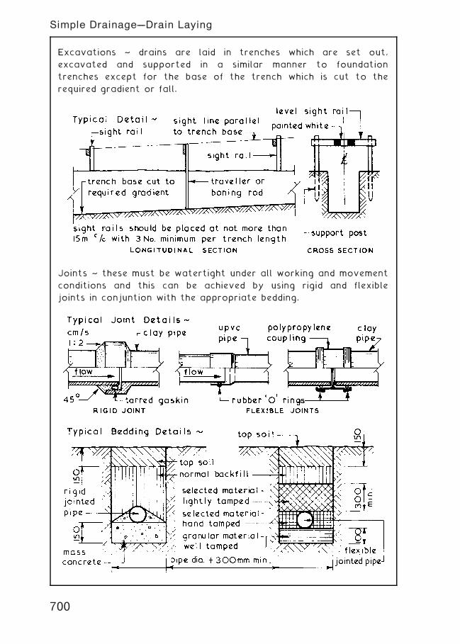
Excavations ~ drains are laid in trenches which are set out,
excavated and supported in a similar manner to foundation
trenches except for the base of the trench which is cut to the
required gradient or fall.
Joints ~ these must be watertight under all working and movement
conditions and this can be achieved by using rigid and flexible
joints in conjuntion with the appropriate bedding.
700
Simple Drainage---Drain Laying
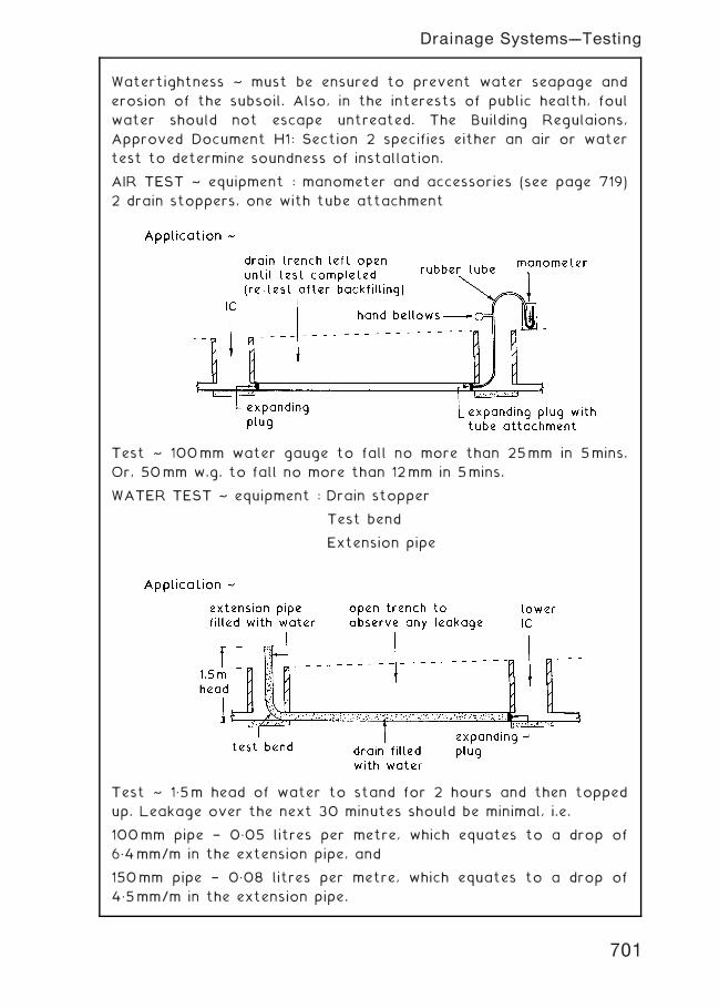
Watertightness ~ must be ensured to prevent water seapage and
erosion of the subsoil. Also, in the interests of public health, foul
water should not escape untreated. The Building Regulaions,
Approved Document H1: Section 2 specifies either an air or water
test to determine soundness of installation.
AIR TEST ~ equipment : manometer and accessories (see page 719)
2 drain stoppers, one with tube attachment
Test ~ 100mm water gauge to fall no more than 25mm in 5mins.
Or, 50mm w.g. to fall no more than 12mm in 5mins.
WATER TEST ~ equipment : Drain stopper
Test bend
Extension pipe
Test ~ 1„5m head of water to stand for 2 hours and then topped
up. Leakage over the next 30 minutes should be minimal, i.e.
100mm pipe † 0„05 litres per metre, which equates to a drop of
6„4mm/m in the extension pipe, and
150mm pipe † 0„08 litres per metre, which equates to a drop of
4„5mm/m in the extension pipe.
701
Drainage Systems---Testing
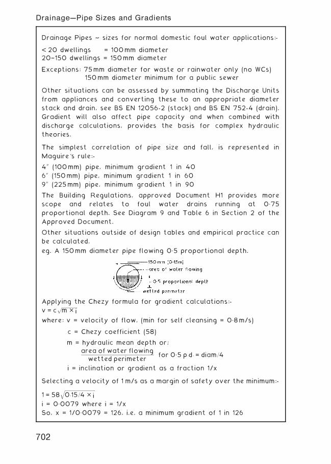
Drainage Pipes ~ sizes for normal domestic foul water applications:-
< 20 dwellings = 100mm diameter20†150 dwellings = 150mm diameter
Exceptions: 75mm diameter for waste or rainwater only (no WCs)
150mm diameter minimum for a public sewer
Other situations can be assessed by summating the Discharge Units
from appliances and converting these to an appropriate diameter
stack and drain, see BS EN 12056-2 (stack) and BS EN 752-4 (drain).
Gradient will also affect pipe capacity and when combined with
discharge calculations, provides the basis for complex hydraulic
theories.
The simplest correlation of pipe size and fall, is represented in
Maguire's rule:-
400 (100mm) pipe, minimum gradient 1 in 40
600 (150mm) pipe, minimum gradient 1 in 60
900 (225mm) pipe, minimum gradient 1 in 90
The Building Regulations, approved Document H1 provides more
scope and relates to foul water drains running at 0„75
proportional depth. See Diagram 9 and Table 6 in Section 2 of the
Approved Document.
Other situations outside of design tables and empirical practice can
be calculated.
eg. A 150mm diameter pipe flowing 0„5 proportional depth.
Applying the Chezy formula for gradient calculations:-
v = cffiffiffiffiffiffiffiffiffiffiffiffiffiffiffiffi
m � ip
where: v = velocity of flow, (min for self cleansing = 0„8m/s)
c = Chezy coefficient (58)
m = hydraulic mean depth or;
area of water flowing
wetted perimeterfor 0„5 p:d: = diam=4
i = inclination or gradient as a fraction 1/x
Selecting a velocity of 1 m/s as a margin of safety over the minimum:-
1 = 58ffiffiffiffiffiffiffiffiffiffiffiffiffiffiffiffiffiffiffiffiffiffiffiffiffiffiffiffiffiffiffi
0:15=4 � iq
i = 0„0079 where i = 1/x
So, x = 1/0„0079 = 126, i.e. a minimum gradient of 1 in 126
702
Drainage---Pipe Sizes and Gradients
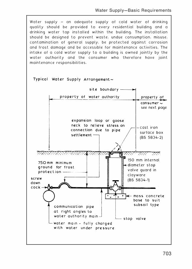
Water supply ~ an adequate supply of cold water of drinking
quality should be provided to every residential building and a
drinking water tap installed within the building. The installation
should be designed to prevent waste, undue consumption, misuse,
contamination of general supply, be protected against corrosion
and frost damage and be accessible for maintenance activities. The
intake of a cold water supply to a building is owned jointly by the
water authority and the consumer who therefore have joint
maintenance responsibilities.
703
Water Supply---Basic Requirements
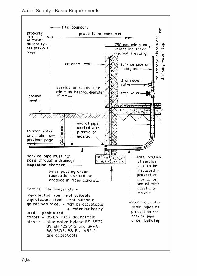
704
Water Supply---Basic Requirements
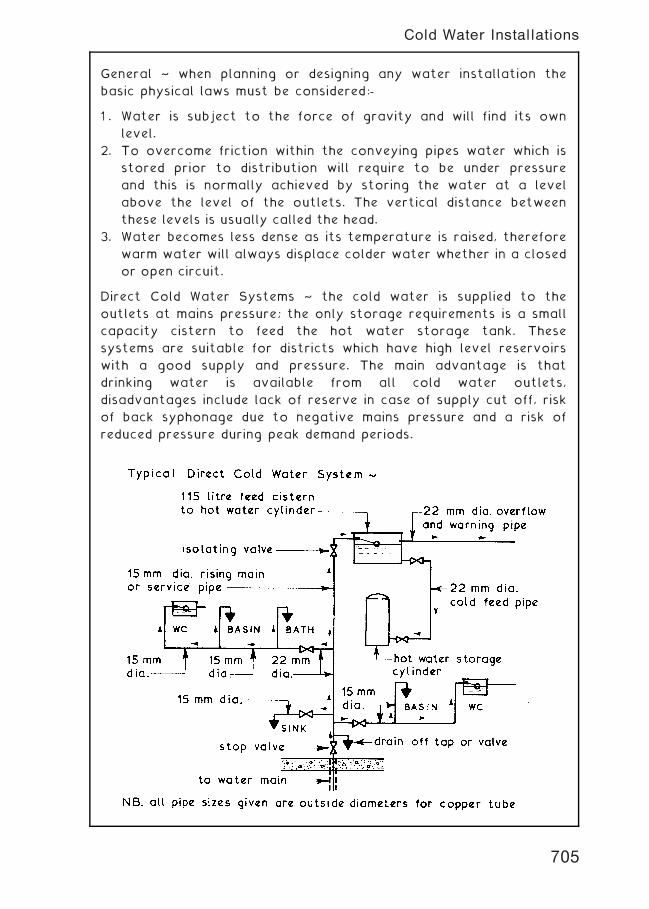
General ~ when planning or designing any water installation the
basic physical laws must be considered:-
1 . Water is subject to the force of gravity and will find its own
level.
2. To overcome friction within the conveying pipes water which is
stored prior to distribution will require to be under pressure
and this is normally achieved by storing the water at a level
above the level of the outlets. The vertical distance between
these levels is usually called the head.
3. Water becomes less dense as its temperature is raised, therefore
warm water will always displace colder water whether in a closed
or open circuit.
Direct Cold Water Systems ~ the cold water is supplied to the
outlets at mains pressure; the only storage requirements is a small
capacity cistern to feed the hot water storage tank. These
systems are suitable for districts which have high level reservoirs
with a good supply and pressure. The main advantage is that
drinking water is available from all cold water outlets,
disadvantages include lack of reserve in case of supply cut off, risk
of back syphonage due to negative mains pressure and a risk of
reduced pressure during peak demand periods.
705
Cold Water Installations
Indirect Systems ~ Cold water is supplied to all outlets from a cold
water storage cistern except for the cold water supply to the
sink(s) where the drinking water tap is connected directly to
incoming supply from the main. This system requires more pipework
than the direct system but it reduces the risk of back syphonage
and provides a reserve of water should the mains supply fail or be
cut off. The local water authority will stipulate the system to be
used in their area.
706
Cold Water Installations
Direct System ~ this is the simplest and least expensive system of
hot water installation. The water is heated in the boiler and the
hot water rises by convection to the hot water storage tank or
cylinder to be replaced by the cooler water from the bottom of
the storage vessel. Hot water drawn from storage is replaced with
cold water from the cold water storage cistern. Direct systems are
suitable for soft water areas and for installations which are not
supplying a central heating circuit.
707
Hot Water Installations
Indirect System ~ this is a more complex system than the direct
system but it does overcome the problem of furring which can
occur in direct hot water systems. This method is therefore
suitable for hard water areas and in all systems where a central
heating circuit is to be part of the hot water installation. Basically
the pipe layouts of the two systems are similar but in the indirect
system a separate small capacity feed cistern is required to charge
and top up the primary circuit. In this system the hot water
storage tank or cylinder is in fact a heat exchanger † see page 712.
708
Hot Water Installations
Mains Fed Indirect System ~ now widely used as an alternative to
conventional systems. It eliminates the need for cold water storage
and saves considerably on installation time. This system is
established in Europe and the USA, but only acceptable in the UK
at the local water authority's discretion. It complements electric
heating systems, where a boiler is not required. An expansion
vessel replaces the standard vent and expansion pipe and may be
integrated with the hot water storage cylinder. It contains a
neoprene diaphragm to separate water from air, the air providing a
`cushion' for the expansion of hot water. Air loss can be
replenished by foot pump as required.
709
Hot Water Installations
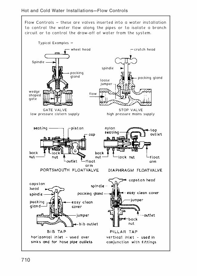
Flow Controls ~ these are valves inserted into a water installation
to control the water flow along the pipes or to isolate a branch
circuit or to control the draw-off of water from the system.
crutch head
packing gland
STOP VALVEhigh pressure mains supply
spindle
loosejumper
flow
GATE VALVElow pressure cistern supply
Spindle
Typical Examples ~
wheel head
packinggland
wedgeshapedgate
710
Hot and Cold Water Installations---Flow Controls
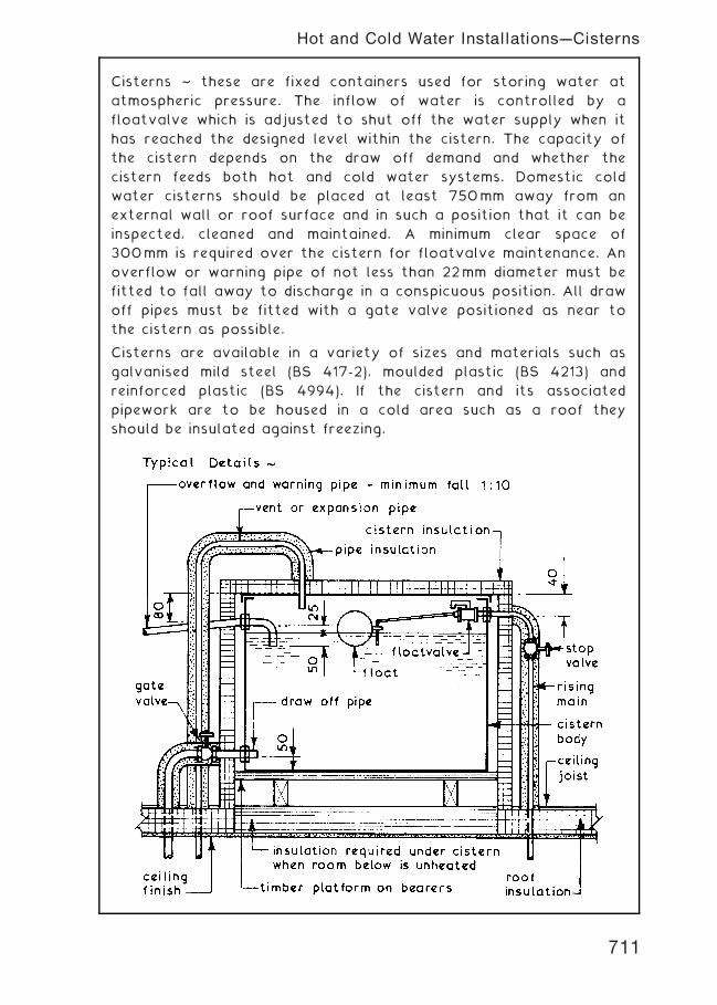
Cisterns ~ these are fixed containers used for storing water at
atmospheric pressure. The inflow of water is controlled by a
floatvalve which is adjusted to shut off the water supply when it
has reached the designed level within the cistern. The capacity of
the cistern depends on the draw off demand and whether the
cistern feeds both hot and cold water systems. Domestic cold
water cisterns should be placed at least 750mm away from an
external wall or roof surface and in such a position that it can be
inspected, cleaned and maintained. A minimum clear space of
300mm is required over the cistern for floatvalve maintenance. An
overflow or warning pipe of not less than 22mm diameter must be
fitted to fall away to discharge in a conspicuous position. All draw
off pipes must be fitted with a gate valve positioned as near to
the cistern as possible.
Cisterns are available in a variety of sizes and materials such as
galvanised mild steel (BS 417-2), moulded plastic (BS 4213) and
reinforced plastic (BS 4994). If the cistern and its associated
pipework are to be housed in a cold area such as a roof they
should be insulated against freezing.
711
Hot and Cold Water Installations---Cisterns
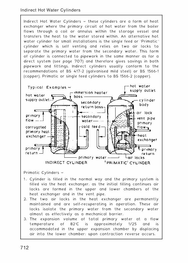
Indirect Hot Water Cylinders ~ these cylinders are a form of heat
exchanger where the primary circuit of hot water from the boiler
flows through a coil or annulus within the storage vessel and
transfers the heat to the water stored within. An alternative hot
water cylinder for small installations is the single feed or `Primatic'
cylinder which is self venting and relies on two air locks to
separate the primary water from the secondary water. This form
of cylinder is connected to pipework in the same manner as for a
direct system (see page 707) and therefore gives savings in both
pipework and fittings. Indirect cylinders usually conform to the
recommendations of BS 417-2 (galvanised mild steel) or BS 1566-1
(copper). Primatic or single feed cylinders to BS 1566-2 (copper).
Primatic Cylinders ~
1 . Cylinder is filled in the normal way and the primary system is
filled via the heat exchanger, as the initial filling continues air
locks are formed in the upper and lower chambers of the
heat exchanger and in the vent pipe.
2. The two air locks in the heat exchanger are permanently
maintained and are self-recuperating in operation. These air
locks isolate the primary water from the secondary water
almost as effectively as a mechanical barrier.
3. The expansion volume of total primary water at a flow
temperature of 82�C is approximately 1/25 and is
accommodated in the upper expansion chamber by displacing
air into the lower chamber; upon contraction reverse occurs.
712
Indirect Hot Water Cylinders
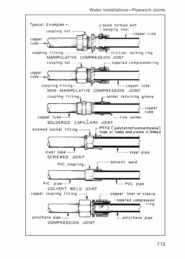
713
Water Installations---Pipework Joints
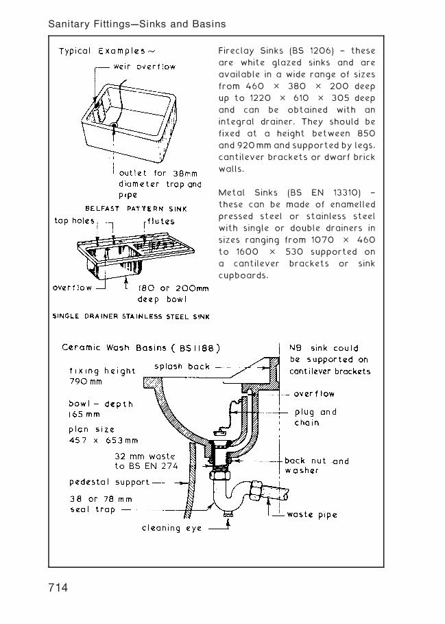
Fireclay Sinks (BS 1206) † these
are white glazed sinks and are
available in a wide range of sizes
from 460 � 380 � 200 deep
up to 1220 � 610 � 305 deep
and can be obtained with an
integral drainer. They should be
fixed at a height between 850
and 920mm and supported by legs,
cantilever brackets or dwarf brick
walls.
Metal Sinks (BS EN 13310) †
these can be made of enamelled
pressed steel or stainless steel
with single or double drainers in
sizes ranging from 1070 � 460
to 1600 � 530 supported on
a cantilever brackets or sink
cupboards.
714
Sanitary Fittings---Sinks and Basins
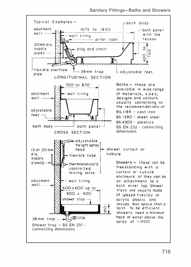
715
Sanitary Fittings---Baths and Showers
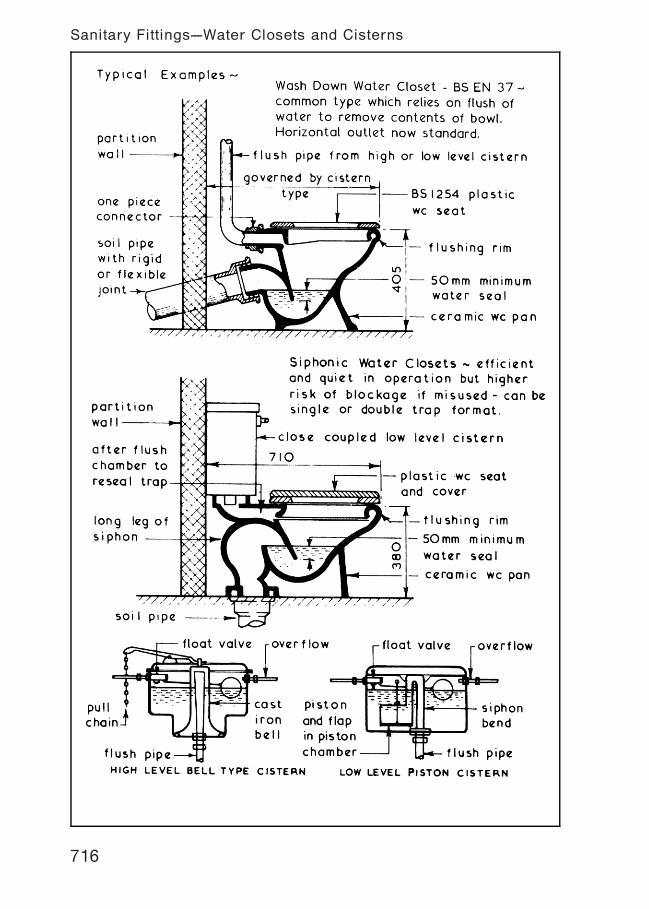
716
Sanitary Fittings---Water Closets and Cisterns
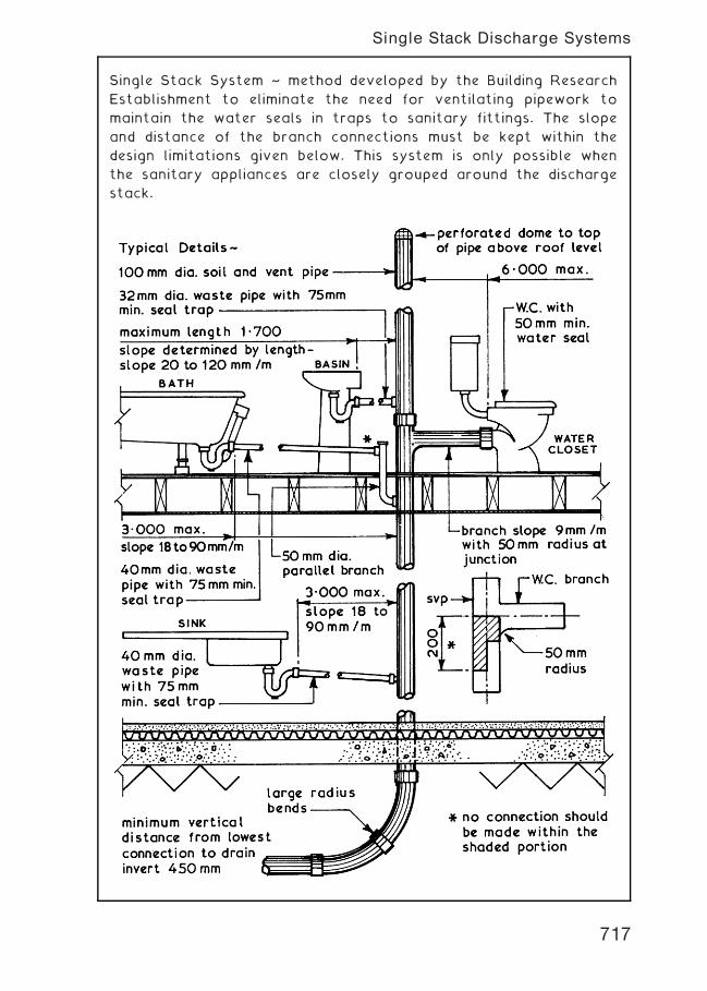
Single Stack System ~ method developed by the Building Research
Establishment to eliminate the need for ventilating pipework to
maintain the water seals in traps to sanitary fittings. The slope
and distance of the branch connections must be kept within the
design limitations given below. This system is only possible when
the sanitary appliances are closely grouped around the discharge
stack.
717
Single Stack Discharge Systems
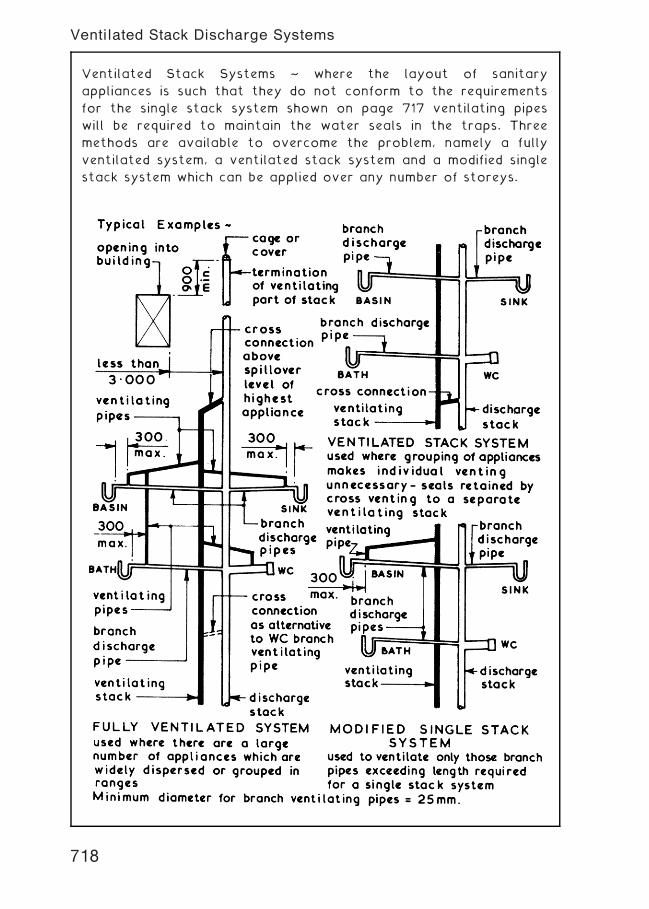
Ventilated Stack Systems ~ where the layout of sanitary
appliances is such that they do not conform to the requirements
for the single stack system shown on page 717 ventilating pipes
will be required to maintain the water seals in the traps. Three
methods are available to overcome the problem, namely a fully
ventilated system, a ventilated stack system and a modified single
stack system which can be applied over any number of storeys.
718
Ventilated Stack Discharge Systems
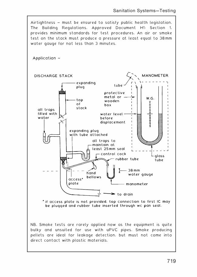
Airtightness ~ must be ensured to satisfy public health legislation.
The Building Regulations, Approved Document H1: Section 1,
provides minimum standards for test procedures. An air or smoke
test on the stack must produce a pressure at least equal to 38mm
water gauge for not less than 3 minutes.
NB. Smoke tests are rarely applied now as the equipment is quite
bulky and unsuited for use with uPVC pipes. Smoke producing
pellets are ideal for leakage detection, but must not come into
direct contact with plastic materials.
719
Sanitation Systems---Testing
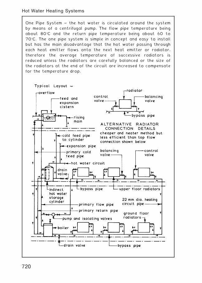
One Pipe System ~ the hot water is circulated around the system
by means of a centrifugal pump. The flow pipe temperature being
about 80�C and the return pipe temperature being about 60 to
70�C. The one pipe system is simple in concept and easy to install
but has the main disadvantage that the hot water passing through
each heat emitter flows onto the next heat emitter or radiator,
therefore the average temperature of successive radiators is
reduced unless the radiators are carefully balanced or the size of
the radiators at the end of the circuit are increased to compensate
for the temperature drop.
720
Hot Water Heating Systems
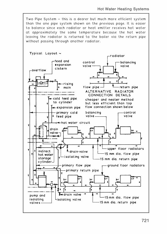
Two Pipe System ~ this is a dearer but much more efficient system
than the one pipe system shown on the previous page. It is easier
to balance since each radiator or heat emitter receives hot water
at approximately the same temperature because the hot water
leaving the radiator is returned to the boiler via the return pipe
without passing through another radiator.
721
Hot Water Heating Systems
Micro Bore System ~ this system uses 6 to 12mm diameter soft
copper tubing with an individual flow and return pipe to each heat
emitter or radiator from a 22mm diameter manifold. The flexible
and unobstrusive pipework makes this system easy to install in
awkward situations but it requires a more powerful pump than that
used in the traditional small bore systems. The heat emitter or
radiator valves can be as used for the one or two pipe small bore
systems alternatively a double entry valve can be used.
722
Hot Water Heating Systems
Controls ~ the range of controls available to regulate the heat
output and timing operations for a domestic hot water heating
system is considerable, ranging from thermostatic radiator control
valves to programmers and controllers.
Typical Example ~
Boiler † fitted with a thermostat to control the temperature of
the hot water leaving the boiler.
Heat Emitters or Radiators † fitted with thermostatically
controlled radiator valves to control flow of hot water to the
radiators to keep room at desired temperature.
Programmer/Controller † this is basically a time switch which can
usually be set for 24 hours, once daily or twice daily time periods
and will generally give separate programme control for the hot
water supply and central heating systems. The hot water cylinder
and room thermostatic switches control the pump and motorised
valve action.
723
Hot Water Heating Systems
Electrical Supply ~ in England and Wales electricity is generated
and supplied by National Power, PowerGen and Nuclear Electric
and distributed through regional supply companies, whereas in
Scotland it is generated, supplied and distributed by Scottish
Power and the Scottish Hydro-Electric Power Company. The
electrical supply to a domestic installation is usually 230 volt
single phase and is designed with the following basic aims:-
1 . Proper earthing to avoid shocks to occupant.
2. Prevention of current leakage.
3. Prevention of outbreak of fire.
724
Electrical Supply---Basic Requirements
Electrical Supply Intake ~ although the electrical supply intake can
be terminated in a meter box situated within a dwelling, most
supply companies prefer to use the external meter box to enable
the meter to be read without the need to enter the premises.
For alternative arrangement of supply intake see previous page
725
Electrical Supply---Basic Requirements
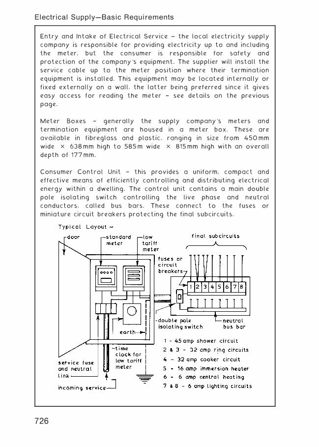
Entry and Intake of Electrical Service ~ the local electricity supply
company is responsible for providing electricity up to and including
the meter, but the consumer is responsible for safety and
protection of the company's equipment. The supplier will install the
service cable up to the meter position where their termination
equipment is installed. This equipment may be located internally or
fixed externally on a wall, the latter being preferred since it gives
easy access for reading the meter † see details on the previous
page.
Meter Boxes † generally the supply company's meters and
termination equipment are housed in a meter box. These are
available in fibreglass and plastic, ranging in size from 450mm
wide � 638mm high to 585m wide � 815mm high with an overall
depth of 177mm.
Consumer Control Unit † this provides a uniform, compact and
effective means of efficiently controlling and distributing electrical
energy within a dwelling. The control unit contains a main double
pole isolating switch controlling the live phase and neutral
conductors, called bus bars. These connect to the fuses or
miniature circuit breakers protecting the final subcircuits.
726
Electrical Supply---Basic Requirements
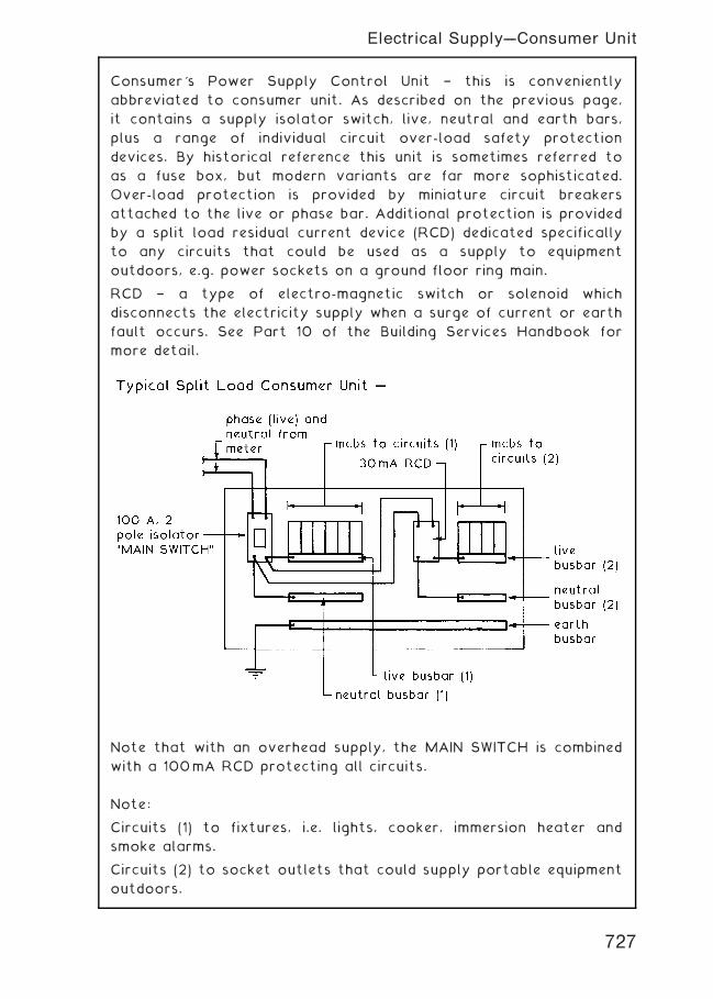
Consumer's Power Supply Control Unit † this is conveniently
abbreviated to consumer unit. As described on the previous page,
it contains a supply isolator switch, live, neutral and earth bars,
plus a range of individual circuit over-load safety protection
devices. By historical reference this unit is sometimes referred to
as a fuse box, but modern variants are far more sophisticated.
Over-load protection is provided by miniature circuit breakers
attached to the live or phase bar. Additional protection is provided
by a split load residual current device (RCD) dedicated specifically
to any circuits that could be used as a supply to equipment
outdoors, e.g. power sockets on a ground floor ring main.
RCD † a type of electro-magnetic switch or solenoid which
disconnects the electricity supply when a surge of current or earth
fault occurs. See Part 10 of the Building Services Handbook for
more detail.
Note that with an overhead supply, the MAIN SWITCH is combined
with a 100mA RCD protecting all circuits.
Note:
Circuits (1) to fixtures, i.e. lights, cooker, immersion heater and
smoke alarms.
Circuits (2) to socket outlets that could supply portable equipment
outdoors.
727
Electrical Supply---Consumer Unit
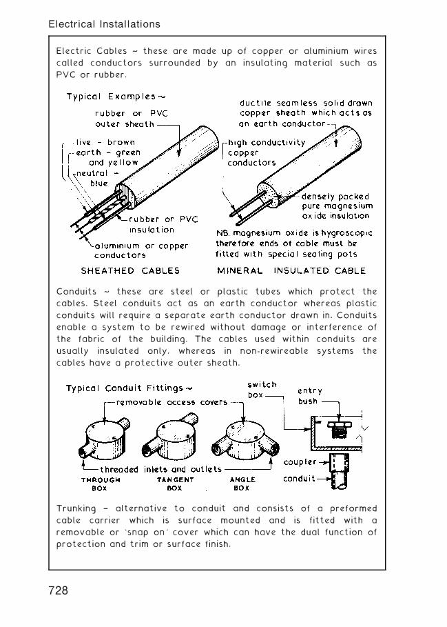
Electric Cables ~ these are made up of copper or aluminium wires
called conductors surrounded by an insulating material such as
PVC or rubber.
Conduits ~ these are steel or plastic tubes which protect the
cables. Steel conduits act as an earth conductor whereas plastic
conduits will require a separate earth conductor drawn in. Conduits
enable a system to be rewired without damage or interference of
the fabric of the building. The cables used within conduits are
usually insulated only, whereas in non-rewireable systems the
cables have a protective outer sheath.
Trunking † alternative to conduit and consists of a preformed
cable carrier which is surface mounted and is fitted with a
removable or `snap on' cover which can have the dual function of
protection and trim or surface finish.
728
Electrical Installations
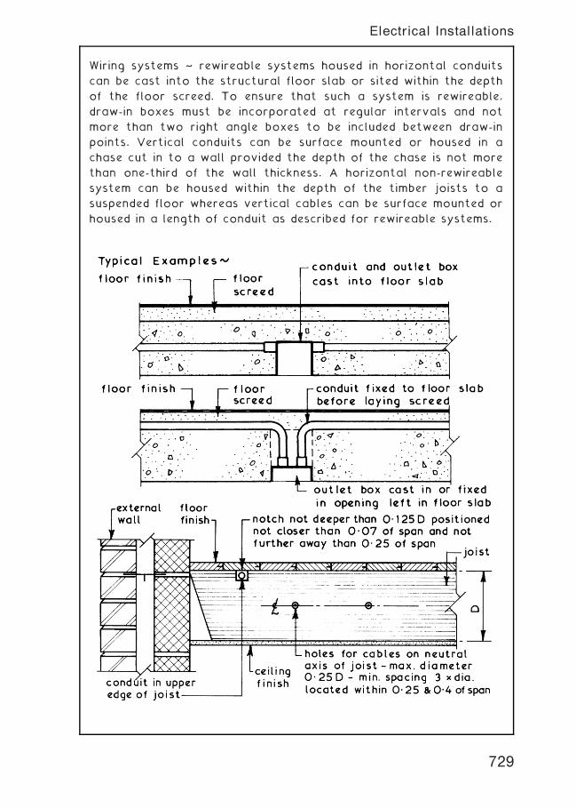
Wiring systems ~ rewireable systems housed in horizontal conduits
can be cast into the structural floor slab or sited within the depth
of the floor screed. To ensure that such a system is rewireable,
draw-in boxes must be incorporated at regular intervals and not
more than two right angle boxes to be included between draw-in
points. Vertical conduits can be surface mounted or housed in a
chase cut in to a wall provided the depth of the chase is not more
than one-third of the wall thickness. A horizontal non-rewireable
system can be housed within the depth of the timber joists to a
suspended floor whereas vertical cables can be surface mounted or
housed in a length of conduit as described for rewireable systems.
729
Electrical Installations
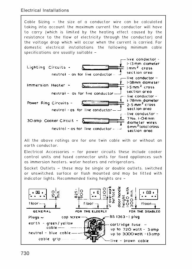
Cable Sizing ~ the size of a conductor wire can be calculated
taking into account the maximum current the conductor will have
to carry (which is limited by the heating effect caused by the
resistance to the flow of electricity through the conductor) and
the voltage drop which will occur when the current is carried. For
domestic electrical installations the following minimum cable
specifications are usually suitable †
All the above ratings are for one twin cable with or without an
earth conductor.
Electrical Accessories ~ for power circuits these include cooker
control units and fused connector units for fixed appliances such
as immersion heaters, water heaters and refrigerators.
Socket Outlets ~ these may be single or double outlets, switched
or unswitched, surface or flush mounted and may be fitted with
indicator lights. Recommended fixing heights are †
730
Electrical Installations
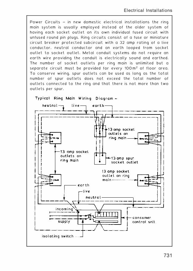
Power Circuits ~ in new domestic electrical installations the ring
main system is usually employed instead of the older system of
having each socket outlet on its own individual fused circuit with
unfused round pin plugs. Ring circuits consist of a fuse or miniature
circuit breaker protected subcircuit with a 32 amp rating of a live
conductor, neutral conductor and an earth looped from socket
outlet to socket outlet. Metal conduit systems do not require an
earth wire providing the conduit is electrically sound and earthed.
The number of socket outlets per ring main is unlimited but a
separate circuit must be provided for every 100m2 of floor area.
To conserve wiring, spur outlets can be used as long as the total
number of spur outlets does not exceed the total number of
outlets connected to the ring and that there is not more than two
outlets per spur.
731
Electrical Installations
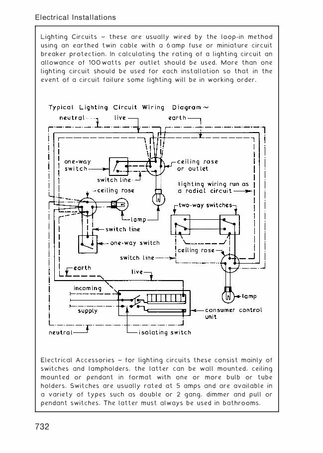
Lighting Circuits ~ these are usually wired by the loop-in method
using an earthed twin cable with a 6amp fuse or miniature circuit
breaker protection. In calculating the rating of a lighting circuit an
allowance of 100watts per outlet should be used. More than one
lighting circuit should be used for each installation so that in the
event of a circuit failure some lighting will be in working order.
Electrical Accessories ~ for lighting circuits these consist mainly of
switches and lampholders, the latter can be wall mounted, ceiling
mounted or pendant in format with one or more bulb or tube
holders. Switches are usually rated at 5 amps and are available in
a variety of types such as double or 2 gang, dimmer and pull or
pendant switches. The latter must always be used in bathrooms.
732
Electrical Installations
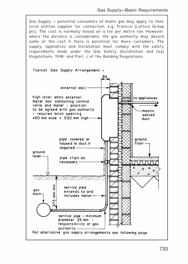
Gas Supply ~ potential consumers of mains gas may apply to their
local utilities supplier for connection, e.g. Transco (Lattice Group
plc). The cost is normally based on a fee per metre run. However,
where the distance is considerable, the gas authority may absorb
some of the cost if there is potential for more customers. The
supply, appliances and installation must comply with the safety
requirements made under the Gas Safety (Installation and Use)
Regulations, 1998, and Part J of the Building Regulations.
733
Gas Supply---Basic Requirements
Gas Service Pipes ~
1 . Whenever possible the service pipe should enter the building
on the side nearest to the main.
2. A service pipe must not pass under the foundations of a
building.
3. No service pipe must be run within a cavity but it may pass
through a cavity by the shortest route.
4. Service pipes passing through a wall or solid floor must be
enclosed by a sleeve or duct which is end sealed with mastic.
5. No service pipe shall be housed in an unventilated void.
6. Suitable materials for service pipes are copper (BS EN 1057) and
steel (BS EN 10255). Polyethylene (BS 7281 or BS EN 1555-2)
is normally used underground.
734
Gas Supply---Basic Requirements
Gas Fires ~ for domestic use these generally have a low energy
rating of less than 7 kW net input and must be installed in
accordance with minimum requirements set out in Part J of the
Building Regulations. Most gas fires connected to a flue are
designed to provide radiant and convected heating whereas the
room sealed balanced flue appliances are primarily convector
heaters.
735
Gas Fires
Gas Fire Flues ~ these can be defined as a passage for the
discharge of the products of combustion to the outside air and can
be formed by means of a chimney, special flue blocks or by using a
flue pipe. In all cases the type and size of the flue as recommended
in Approved Document J, BS EN 1806 and BS 5440 will meet the
requirements of the Building Regulations.
736
Gas Fires
Open Fireplaces ~ for domestic purposes these are a means of
providing a heat source by consuming solid fuels with an output
rating of under 50 kW. Room-heaters can be defined in a similar
manner but these are an enclosed appliance as opposed to the
open recessed fireplace.
Components ~ the complete construction required for a domestic
open fireplace installation is composed of the hearth, fireplace
recess, chimney, flue and terminal.
See also BS 5854: Code of practice for flues and flue structures in
buildings.
737
Open Fireplaces and Flues
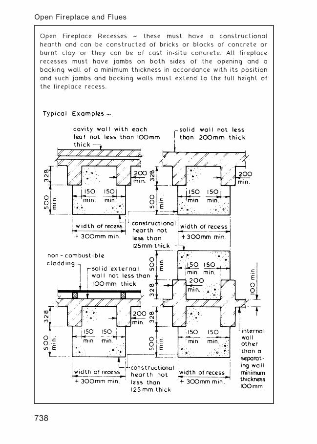
Open Fireplace Recesses ~ these must have a constructional
hearth and can be constructed of bricks or blocks of concrete or
burnt clay or they can be of cast in-situ concrete. All fireplace
recesses must have jambs on both sides of the opening and a
backing wall of a minimum thickness in accordance with its position
and such jambs and backing walls must extend to the full height of
the fireplace recess.
738
Open Fireplace and Flues
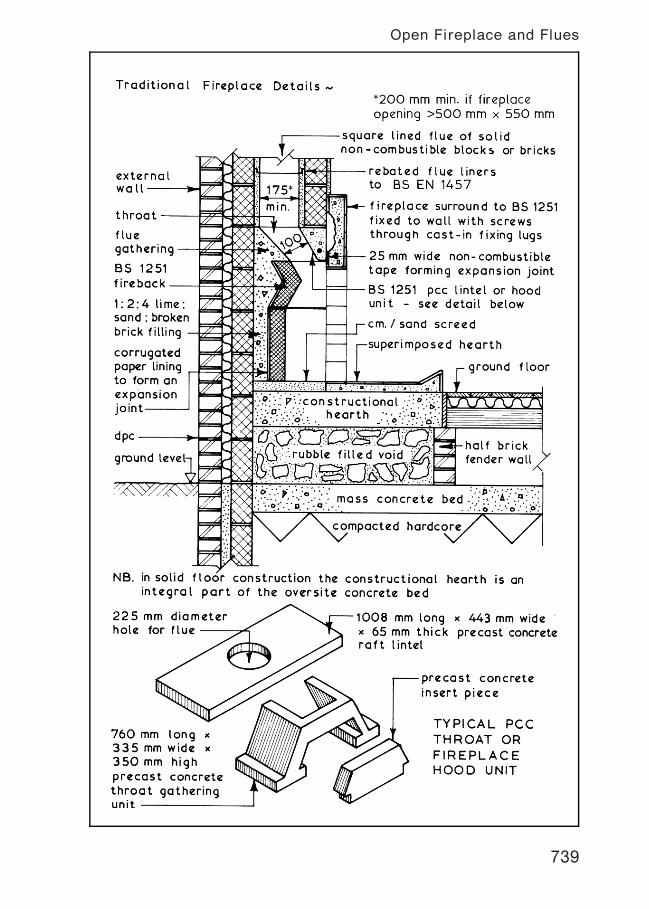
739
Open Fireplace and Flues
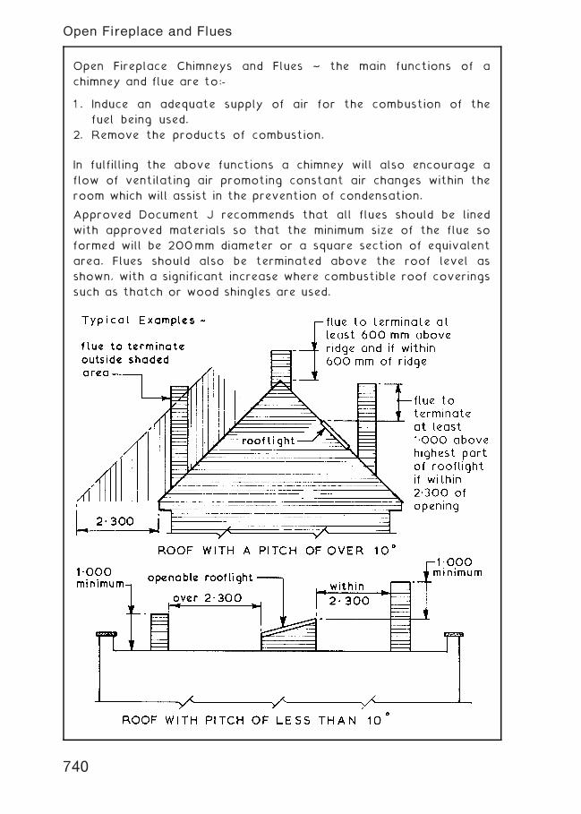
Open Fireplace Chimneys and Flues ~ the main functions of a
chimney and flue are to:-
1 . Induce an adequate supply of air for the combustion of the
fuel being used.
2. Remove the products of combustion.
In fulfilling the above functions a chimney will also encourage a
flow of ventilating air promoting constant air changes within the
room which will assist in the prevention of condensation.
Approved Document J recommends that all flues should be lined
with approved materials so that the minimum size of the flue so
formed will be 200mm diameter or a square section of equivalent
area. Flues should also be terminated above the roof level as
shown, with a significant increase where combustible roof coverings
such as thatch or wood shingles are used.
740
Open Fireplace and Flues
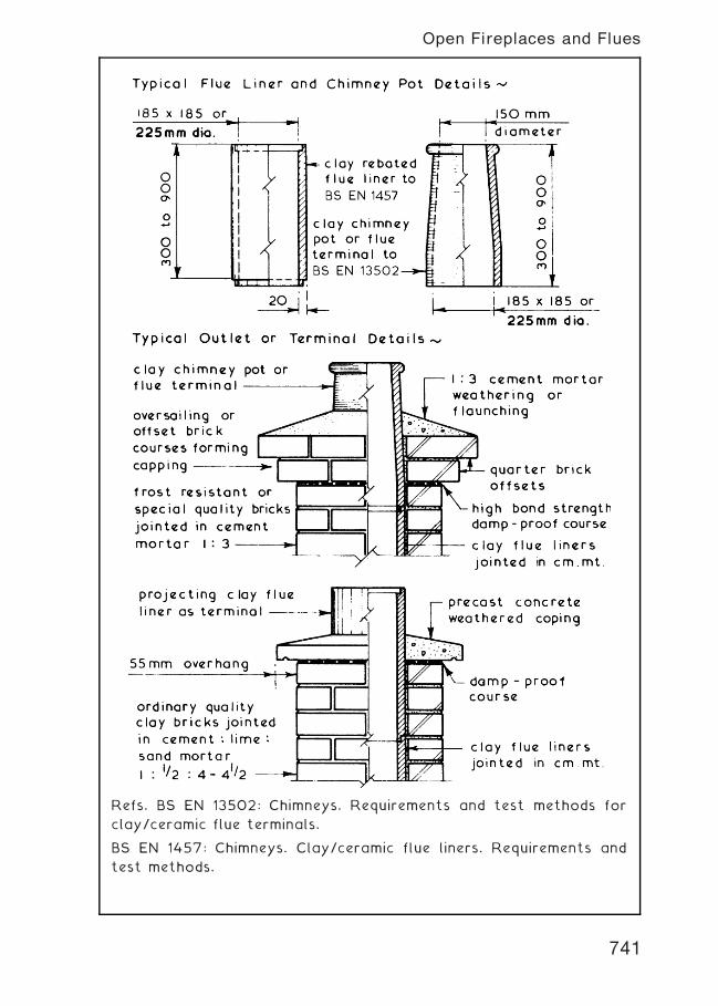
Refs. BS EN 13502: Chimneys. Requirements and test methods for
clay/ceramic flue terminals.
BS EN 1457: Chimneys. Clay/ceramic flue liners. Requirements and
test methods.
741
Open Fireplaces and Flues
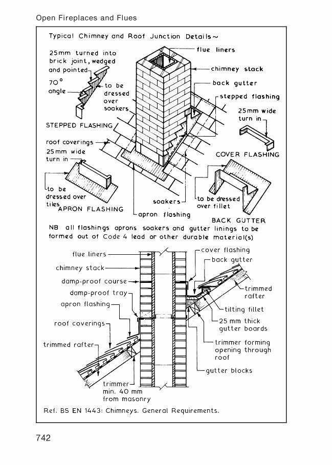
742
Open Fireplaces and Flues
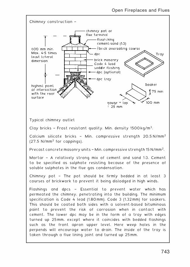
Chimney construction †
Typical chimney outlet
Clay bricks † Frost resistant quality. Min. density 1500kg/m3.
Calcium silicate bricks † Min. compressive strength 20.5 N/mm2
(27.5 N/mm2 for cappings).
Precast concretemasonry units †Min. compressive strength 15 N/mm2.
Mortar † A relatively strong mix of cement and sand 1:3. Cement
to be specified as sulphate resisting because of the presence of
soluble sulphates in the flue gas condensation.
Chimney pot † The pot should be firmly bedded in at least 3
courses of brickwork to prevent it being dislodged in high winds.
Flashings and dpcs † Essential to prevent water which has
permeated the chimney, penetrating into the building. The minimum
specification is Code 4 lead (1.80mm), Code 3 (1.32mm) for soakers.
This should be coated both sides with a solvent-based bituminous
paint to prevent the risk of corrosion when in contact with
cement. The lower dpc may be in the form of a tray with edges
turned up 25mm, except where it coincides with bedded flashings
such as the front apron upper level. Here weep holes in the
perpends will encourage water to drain. The inside of the tray is
taken through a flue lining joint and turned up 25mm.
743
Open Fireplaces and Flues
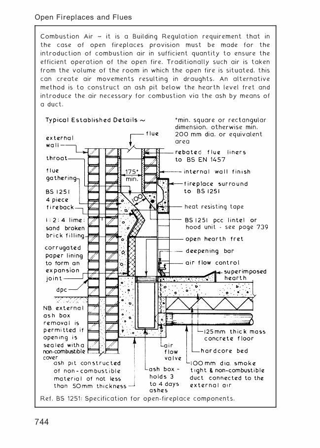
Combustion Air ~ it is a Building Regulation requirement that in
the case of open fireplaces provision must be made for the
introduction of combustion air in sufficient quantity to ensure the
efficient operation of the open fire. Traditionally such air is taken
from the volume of the room in which the open fire is situated, this
can create air movements resulting in draughts. An alternative
method is to construct an ash pit below the hearth level fret and
introduce the air necessary for combustion via the ash by means of
a duct.
Ref. BS 1251: Specification for open-fireplace components.
744
Open Fireplaces and Flues
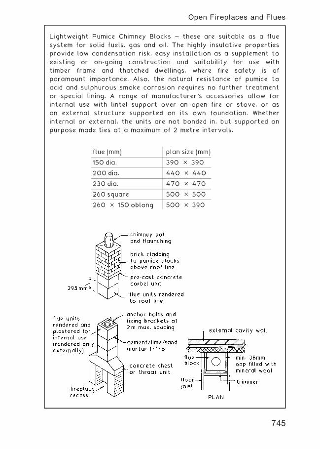
Lightweight Pumice Chimney Blocks ~ these are suitable as a flue
system for solid fuels, gas and oil. The highly insulative properties
provide low condensation risk, easy installation as a supplement to
existing or on-going construction and suitability for use with
timber frame and thatched dwellings, where fire safety is of
paramount importance. Also, the natural resistance of pumice to
acid and sulphurous smoke corrosion requires no further treatment
or special lining. A range of manufacturer's accessories allow for
internal use with lintel support over an open fire or stove, or as
an external structure supported on its own foundation. Whether
internal or external, the units are not bonded in, but supported on
purpose made ties at a maximum of 2 metre intervals.
flue (mm) plan size (mm)
150 dia. 390 � 390
200 dia. 440 � 440
230 dia. 470 � 470
260 square 500 � 500
260 � 150 oblong 500 � 390
745
Open Fireplaces and Flues
Fire Protection of Services Openings ~ penetration of compartment
walls and floors (zones of restricted fire spread, e.g. flats in one
building), by service pipes and conduits is very difficult to avoid.
An exception is where purpose built service ducts can be
accommodated. The Building Regulations, Approved Document
B3:Sections 7 [Vol. 1] and 10 [Vol. 2] determines that where a pipe
passes through a compartment interface, it must be provided with
a proprietary seal. Seals are collars of intumescent material which
expands rapidly when subjected to heat, to form a carbonaceous
charring. The expansion is sufficient to compress warm plastic and
successfully close a pipe void for up to 4 hours.
In some circumstances fire stopping around the pipe will be
acceptable, provided the gap around the pipe and hole through the
structure are filled with non-combustible material. Various
materials are acceptable, including reinforced mineral fibre, cement
and plasters, asbestos rope and intumescent mastics.
Pipes of low heat resistance, such as PVC, lead, aluminium alloys
and fibre cement may have a protective sleeve of non-combustible
material extending at least 1 m either side of the structure.
746
Services---Fire Stops and Seals
Telephone Installations ~ unlike other services such as water, gas
and electricity, telephones cannot be connected to a common
mains supply. Each telephone requires a pair of wires connecting
it to the telephone exchange. The external supply service and
connection to the lead-in socket is carried out by
telecommunication engineers. Internal extensions can be installed
by the site electrician.
747
Telephone Installations---Basic Requirements
Electronic Installations † in addition to standard electrical and
telecommunication supplies into buildings, there is a growing
demand for cable TV, security cabling and broadband access to the
Internet. Previous construction practice has not foreseen the need
to accommodate these services from distribution networks into
buildings, and retrospective installation through underground
ducting is both costly and disruptive to the structure and
surrounding area, particularly when repeated for each different
service. Ideally there should be a common facility integral with new
construction to permit simple installation of these communication
services at any time. A typical installation will provide connection
from a common external terminal chamber via underground ducting
to a terminal distribution box within the building. Internal
distribution is through service voids within the structure or
attached trunking.
748
Electronic Communications Installations

INDEX
Access for disabled, 456�8Access to sites, 84Accommodation on sites, 85�6Active earth pressures, 233, 245�6Adhesives, 517Admixtures, 254, 338Aerated concrete floor units, 620Aggregate samples, 104Air lock hopper, 214Air test, 701, 719Air tightness, infiltration and permeability,
442, 445, 447�8, 455, 519Alternating tread stair, 636Aluminium alloy infill panels, 554Aluminium alloy windows, 364, 366Anchor bars, 464Anchor straps, 425, 608Anchorages, 252, 489�91, 493, 544Angle Piling, 282Angledozers, 155Angles:
structural steel, 494�5surveying, 117
Angles of repose, 232, 245�6, 263Annexed buildings, 312�13Anti-shear studs, 463Apex hinges, 512Approved Documents, 52�4Approved inspector, 52, 55Apron cladding panels, 564Apron flashing, 742�3Arches, 340�3Asphalt tanking, 256�7Attached piers, 307�8, 311�12Augers, 74, 216�17Automatic level, 115Axial grid, 47Axonometric projection, 24
Backacter/hoe, 33, 154, 161, 163, 250Backgutter, 742Backshore, 141Balanced flue, 735Balloon frame, 386Balusters, 629, 632�5, 638, 641, 647,
649, 651Balustrade, 13, 641�2, 647, 649�51
Bar chart, 34, 84Bargeboard, 525Barrel vaults, 9, 537Basement excavation, 247�50Basement insulation, 259Basement waterproofing, 254�8Basements, 247�59Basic forms and types of structure, 5�10Basic formwork, 478�82Basic module grid, 46Basic roof forms, 392�4Basins, 714Batch mixers, 183�4Baths, 715Bay window, 358Beam and block floor, 599Beam and pot floor, 621Beam and slab raft, 210Beam formwork, 479�80Beam to column connection, 486, 499�500Beam design:
concrete, 465�7steel, 506�8timber, 611�13
Beams, 464, 495�500, 514�15, 518�19Bearing piles, 212Beech, 677Benchmark, 67, 111, 113�16Bending moment, 506, 510, 612Bentonite, 215, 291�2Bib tap, 710Binder, 669Binders/binding � reinforcement, 210, 464,
468�70Binders/binding � shoring, 141, 249Birdcage scaffold, 134Block bonding, 574Block plan, 27, 41Block walls, 574�8Blockboard, 678Bloom base, 209, 501Boarded web girder, 518Bolection moulding, 675Bolt box, 484, 499, 501Bolted connections, 499�500, 503Bolts � types, 503Bonding, bricks, 305�11
749

Bonnet tiles, 402, 406Boot lintels, 344Bore hole, 68, 76Borrowed light, 585Bottom shore, 141Box beam, 518Box caisson, 274Box pile foundation, 222Braced structures, 521Breather membrane, 390, 401, 404�5Brick:
corbel, 317�18, 741, 743dentil, 318dog-tooth, 318infill panels, 553internal walls, 573jointing and pointing, 314panel walls, 550plinths, 316�17purpose made, 316retaining walls, 230�1, 234�5, 240�1specials, 315�16strength, 335�6testing, 102underpinning, 277�8
Brick bonding:attached piers, 307�8English bond, 305, 307, 697Flemish bond, 308principles, 306quetta bond, 240�1special bonds, 240, 305�6, 309�10stack bond, 310stretcher bond, 306zipper bond, 305
Brickwork cladding support, 551Bridging of dpc’s, 331British Standards, 59Brown field, 300Buckling factor, 471Builders plant, 152�88Building control, 55Building Regulations, 52�7Building Regulations application, 57Building Regulations exemptions, 56Building Research Establishment, 62Building surveyor, 28�32Built environment, 2�4Built-up roofing felt, 417�18, 420�1Bulk density of soil, 82Bulking of sand, 103Bulldozer, 155Busbar, 726�7
Cab crane control, 178Cable sizing, 730
Caissons, 274�5Calculated brickwork, 335�6Calculation of storage space, 98Camber arch, 341Cantilever:
beam, 5, 464foundations, 211retaining wall, 236scaffold, 136stairs, 640, 646structures, 520
Cap tendons, 490Carbon emissions, 32, 446�7Carbon index, 446Cartridge fuse, 730Cased pile foundation, 223Casein adhesive, 517Casement windows:
ironmongery, 353metal, 352, 364timber, 350�1
Castellated beam, 497Cast-in wall ties, 553Cast insitu diaphragm walls, 252, 291Cast insitu pile foundation, 226Cast-on finishes, 567Cavity barrier/closer, 332, 387, 404, 444,
453�4, 562, 579�80Cavity fire stop, 579�80Cavity tray, 206, 342�3Cavity walls, 320�5, 450�1Cedar, 676Ceilings:
plasterboard, 592, 664, 666suspended, 665�8
Cellular basement, 251Cement, 266�7, 336, 338Cement grouts, 293Central heating, 720�2Centres, 341, 343Certificates of ownership, 41, 45Channel floor units, 621Channels � structural steel, 494�5Checked rebates in walls, 347Chemical dpc, 329�30Chemical grouts, 293Cheshire auger, 74Chezy formula, 702Chimney pot, 22, 741, 745Chimneys, 737, 740�3Chipboard, 601, 679Circular bay window, 358Circular column, 468CI/SfB system, 64Cisterns, 705�8, 711, 716, 720�2Cladding panels, 551�2
750
Index
Clamp vibrator, 187Classification of piled foundations, 212�13Clay cutter, 214Clear glass, 361Client, 49Climbing cranes, 177, 181Climbing formwork, 238Closed couple roof, 396Code for Sustainable Homes, 58Codes of Practice, 59Cofferdams, 272�3Coil wall ties, 237Cold bridging, 332, 366, 452�3, 599Cold deck, 417, 420Cold water installations, 703�6Collar roof, 396Column design, 470�1, 509Column formwork, 481�2Column to column connection, 485, 500Column underpinning, 283Columns, 468, 495�6, 499�501Combined column foundation, 209Combined method, 440Combined pad foundation, 198Combined system, 695Combustion air, 744Communicating information:
bar chart, 34, 84elevations, 23, 26floor plans, 21, 23, 26, 38, 40isometric projection, 24orthographic projection, 23perspective projection, 25sketches, 22
Compartment floor, 18, 477Compartment wall, 18, 579Complete excavation, 249Completion certificate, 31Composite beams and joists, 518�19Composite boarding, 678�9Composite floors, 463, 621Composite lintels, 344Composite panel, 554Composite piled foundation, 223�4Compound sections, 496Compressed strawboard, 678Compressible joints, 550, 576, 644�5Concrete:
admixtures, 254beam design, 465�7claddings, 563�5column design, 470�1floor screed, 604�5mixers, 183�4placing, 186�7production, 266�71
pumps, 186slab design, 465�7stairs, 639�47surface defects, 568surface finishes, 566�7test cubes, 105testing, 106�8
Concrete production:designated mix, 270designed mix, 270materials, 266prescribed mix, 270site storage, 86, 267specification, 270standard mix, 270supply, 271volume batching, 268weight batching, 269
Concreting, 182Concreting plant, 182�8Conductivity, 435�6Conduit and fittings, 728�9Conoid roof, 9, 539Consolidation of soil, 83Construction activities, 19, 34Construction, Design and Management
Regs., 48�9Construction joints, 121, 255, 576, 602Construction Products Directive, 61Construction Regulations, 48�9Consumer control unit, 724�7, 731�2Contaminated subsoil, 300�1Contiguous piling, 290Continuous column foundations, 208Contraction joints, 121, 576Controlling dimensions, 47Controlling grid and lines, 46�7Cooker circuit cable, 730Coping stones, 230, 234�5, 323Corbelled brickwork, 317�18, 741, 743Core drilling, 75Core structures, 521Cored floor units, 589CORGI, 444Cor-ply beam, 518Cornice, 675Corrugated sheet, 524�8Coulomb’s line, 82Coulomb’s wedge theory, 246Counter batten, 401, 405Couple roof, 396Cove mouldings, 591, 664Cover flashing, 742CPI System of Coding, 63Cracking in walls, 195Cradles, 135
751
Index
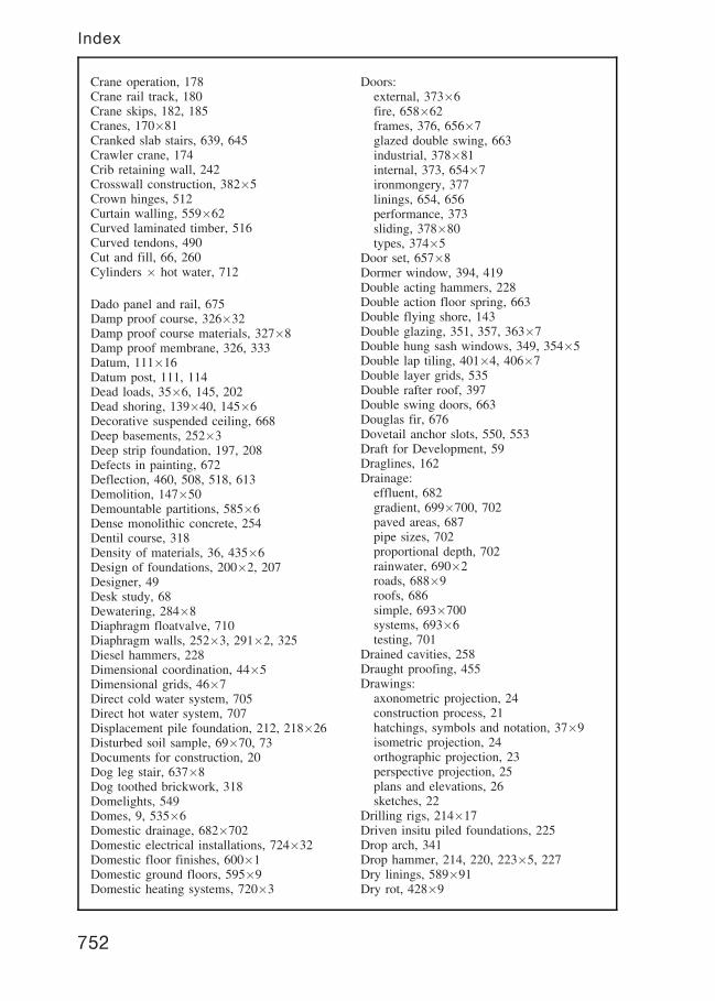
Crane operation, 178Crane rail track, 180Crane skips, 182, 185Cranes, 170�81Cranked slab stairs, 639, 645Crawler crane, 174Crib retaining wall, 242Crosswall construction, 382�5Crown hinges, 512Curtain walling, 559�62Curved laminated timber, 516Curved tendons, 490Cut and fill, 66, 260Cylinders � hot water, 712
Dado panel and rail, 675Damp proof course, 326�32Damp proof course materials, 327�8Damp proof membrane, 326, 333Datum, 111�16Datum post, 111, 114Dead loads, 35�6, 145, 202Dead shoring, 139�40, 145�6Decorative suspended ceiling, 668Deep basements, 252�3Deep strip foundation, 197, 208Defects in painting, 672Deflection, 460, 508, 518, 613Demolition, 147�50Demountable partitions, 585�6Dense monolithic concrete, 254Dentil course, 318Density of materials, 36, 435�6Design of foundations, 200�2, 207Designer, 49Desk study, 68Dewatering, 284�8Diaphragm floatvalve, 710Diaphragm walls, 252�3, 291�2, 325Diesel hammers, 228Dimensional coordination, 44�5Dimensional grids, 46�7Direct cold water system, 705Direct hot water system, 707Displacement pile foundation, 212, 218�26Disturbed soil sample, 69�70, 73Documents for construction, 20Dog leg stair, 637�8Dog toothed brickwork, 318Domelights, 549Domes, 9, 535�6Domestic drainage, 682�702Domestic electrical installations, 724�32Domestic floor finishes, 600�1Domestic ground floors, 595�9Domestic heating systems, 720�3
Doors:external, 373�6fire, 658�62frames, 376, 656�7glazed double swing, 663industrial, 378�81internal, 373, 654�7ironmongery, 377linings, 654, 656performance, 373sliding, 378�80types, 374�5
Door set, 657�8Dormer window, 394, 419Double acting hammers, 228Double action floor spring, 663Double flying shore, 143Double glazing, 351, 357, 363�7Double hung sash windows, 349, 354�5Double lap tiling, 401�4, 406�7Double layer grids, 535Double rafter roof, 397Double swing doors, 663Douglas fir, 676Dovetail anchor slots, 550, 553Draft for Development, 59Draglines, 162Drainage:
effluent, 682gradient, 699�700, 702paved areas, 687pipe sizes, 702proportional depth, 702rainwater, 690�2roads, 688�9roofs, 686simple, 693�700systems, 693�6testing, 701
Drained cavities, 258Draught proofing, 455Drawings:
axonometric projection, 24construction process, 21hatchings, symbols and notation, 37�9isometric projection, 24orthographic projection, 23perspective projection, 25plans and elevations, 26sketches, 22
Drilling rigs, 214�17Driven insitu piled foundations, 225Drop arch, 341Drop hammer, 214, 220, 223�5, 227Dry linings, 589�91Dry rot, 428�9
752
Index

Dumpers, 165, 185Dumpling, 248Dynamic compaction, 295, 298
Earth pressures, 233, 245�6Earthworks for roads, 118�19Eaves:
closure piece, 525�6details, 403�7, 409�10, 415, 417�18,
421, 449filler piece, 525�6gutter, 403, 409, 528, 686, 690ventilation, 403, 409�10, 417, 421�4
Effective height of walls, 337Effective length of columns, 471, 509Effective thickness of walls, 335, 337Effluents, 682Electrical cables, 730Electrical installations, 728�32Electrical site lighting, 90�2Electricity:
domestic supply, 724�7supply to sites, 93
Elevations, 23, 26End bearing pile foundation, 212Energy efficiency, 32, 442�3, 447�8Energy performance certificate, 32Energy rating, 32, 442, 445�6Energy roof system, 527English bond, 305, 307, 697Environment, 2�4Equivalent area, 470�1Espagnolette, 357European spruce, 676European Standards, 60Excavating machines, 159�63, 250Excavations:
basement, 247�50dewatering, 285, 288oversite, 260pier holes, 261reduced level, 260setting out, 111�12trench, 261temporary support, 263�5
Expansion joint, 121, 255, 538, 550,576, 600
Exposed aggregate, 566�7External asphalt tanking, 256External doors, 373�6External envelope, 17, 304External escape stairs, 648
Facade bracing, 126Face grid, 47Face shovel, 160, 250
Facings to panel walls, 552Factories Acts, 48Fencing, 85�9, 96, 109Festoon lighting, 92Fibreboard, 679Field study, 68Finger joint, 514Finishes, 14, 566�7, 587�8, 600�1,
669�72Fin wall, 324Fire:
doors, 658�62doorsets and assemblies, 658protection of masonry walls, 578protection of steelwork, 504�5, 584protection of timber floors, 614resistance 332, 504�5, 578, 584, 614, 659resistance of steelwork, 504resistance/insulation, 614, 659resistance/integrity, 332, 614, 659resisting doors, 661stops and seals, 579�80, 746
Fire back, 739, 744Fireplaces and flues, 736�45Fish plates, 500Fixed portal frame, 510�11, 513Flashings, 323, 407, 418, 421, 742�3Flat roofs, 392, 416�21, 424, 431Flat sawn timber, 515Flat slabs, 460�2, 615Flat top girder, 529, 532Flemish bond, 308Flexible paving, 119Flight auger, 74Flitch beam, 518Float valves, 710�11Floating floor, 599, 627�8Floating pile foundation, 212Floor plans, 26, 40Floor springs, 663Floors:
domestic ground, 595�9finishes, 600�1fixings, 619flat slab, 460�2, 615hollow pot, 618�19insitu RC suspended, 460�2, 615large cast insitu, 602�3precast concrete, 620�2ribbed, 616�17screeds, 595�6, 604�5sound insulation, 624, 627�8suspended concrete ground, 334, 598�9suspended timber ground, 595, 597suspended timber upper, 606�11waffle, 616�17
753
Index

Flue blocks, 736, 745Flue lining, 736�7, 739, 741�2, 744Flush bored pile foundation, 213, 215Fly jib, 173�4Flying shore, 139, 142�4Folded plate construction, 8Footpaths, 122Forklift truck, 166Formwork:
beams, 479�80columns, 481�2principles, 478slab, 462stairs, 643
Foundation hinges, 512Foundations:
basic sizing, 200beds, 199calculated sizing, 202defects, 192�5functions, 190grillage, 209isolated pad, 209piled, 205, 213�29raft, 206�7short bored piled, 205, 212�14simple reinforced, 204stepped, 203strip width guide, 201subsoil movement, 191�4types, 207�11
Four-in-one bucket, 158Four wheeled grader, 157Framed structures, 464, 468, 483�6,
499�500, 520Freyssinet anchorage, 491Friction hinge, 357Friction piling, 212Frieze, 675Frodingham box pile, 222Frodingham sheet pile, 273Full height casting, 237Fungicide, 429Furniture beetle, 426
Gabion wall, 244Gable end roof, 393, 395Gambrel roof, 394, 400Gantry crane, 175Gantry girder, 496Gantry scaffolding, 138Garage, 312�13Garden wall bonds, 309Gas:
fires, 736flues, 736�7, 745
service intake, 733�4supply, 733�4
Gas resistant membranes, 333�4, 599Gate valve, 710�11Gauge box, 268Geodistic dome, 535Girders, 496, 529, 531�2Glass and glazing, 361�70Glass block wall, 371�2Glass manifestation, 370Glazed cladding, 557�8Gluelam, 514�7Grab bucket, 162Graders, 157Granular soil shell, 214Green field, 300, 333Green roof, 431�2Grillage foundation, 209Groins, 539Ground anchors, 252, 292, 493, 544Ground freezing, 294Ground vibration, 295�7Ground water, 66, 68, 76, 284Ground water control, 285�94Grouting-subsoil, 293Grouting-tiles, 594Guard rail, 127�9, 131, 133, 136�7Gusset base, 501Gusset plate, 513, 523, 526
Half hour fire door, 659Hammer head junction, 118Hand auger, 74Hand auger holes, 69Handrail, 629�30, 632, 634, 638, 641�2,
647�9, 651�3Hardwoods, 677Half space landing, 637Health and Safety at Work, etc. Act, 48, 50Hearths, 737�9, 744Helical binding, 468�9Helical stairs, 641Helmets, 220, 224Hemispherical dome, 536Herringbone strutting, 607HETAS, 444High performance window, 351Highway dumpers, 165Hinge or pin joints, 512Hipped roof, 393, 395Hip tiles, 402, 406Hoardings, 85�9Hoists, 167�8Holding down bolts, 484, 499, 501, 512�13Hollow box floor units, 620Hollow pot floor, 618�19
754
Index
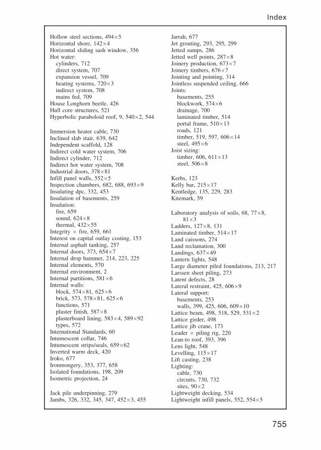
Hollow steel sections, 494�5Horizontal shore, 142�4Horizontal sliding sash window, 356Hot water:
cylinders, 712direct system, 707expansion vessel, 709heating systems, 720�3indirect system, 708mains fed, 709
House Longhorn beetle, 426Hull core structures, 521Hyperbolic paraboloid roof, 9, 540�2, 544
Immersion heater cable, 730Inclined slab stair, 639, 642Independent scaffold, 128Indirect cold water system, 706Indirect cylinder, 712Indirect hot water system, 708Industrial doors, 378�81Infill panel walls, 552�5Inspection chambers, 682, 688, 693�9Insulating dpc, 332, 453Insulation of basements, 259Insulation:
fire, 659sound, 624�8thermal, 432�55
Integrity � fire, 659, 661Interest on capital outlay costing, 153Internal asphalt tanking, 257Internal doors, 373, 654�7Internal drop hammer, 214, 223, 225Internal elements, 570Internal environment, 2Internal partitions, 581�6Internal walls:
block, 574�81, 625�6brick, 573, 578�81, 625�6functions, 571plaster finish, 587�8plasterboard lining, 583�4, 589�92types, 572
International Standards, 60Intumescent collar, 746Intumescent strips/seals, 659�62Inverted warm deck, 420Iroko, 677Ironmongery, 353, 377, 658Isolated foundations, 198, 209Isometric projection, 24
Jack pile underpinning, 279Jambs, 326, 332, 345, 347, 452�3, 455
Jarrah, 677Jet grouting, 293, 295, 299Jetted sumps, 286Jetted well points, 287�8Joinery production, 673�7Joinery timbers, 676�7Jointing and pointing, 314Jointless suspended ceiling, 666Joints:
basements, 255blockwork, 574�6drainage, 700laminated timber, 514portal frame, 510�13roads, 121timber, 519, 597, 606�14steel, 495�6
Joist sizing:timber, 606, 611�13steel, 506�8
Kerbs, 123Kelly bar, 215�17Kentledge, 135, 229, 283Kitemark, 59
Laboratory analysis of soils, 68, 77�8,81�3
Ladders, 127�8, 131Laminated timber, 514�17Land caissons, 274Land reclamation, 300Landings, 637�49Lantern lights, 548Large diameter piled foundations, 213, 217Larssen sheet piling, 273Latent defects, 28Lateral restraint, 425, 606�9Lateral support:
basements, 253walls, 399, 425, 606, 609�10
Lattice beam, 498, 518, 529, 531�2Lattice girder, 498Lattice jib crane, 173Leader � piling rig, 220Lean-to roof, 393, 396Lens light, 548Levelling, 115�17Lift casting, 238Lighting:
cable, 730circuits, 730, 732sites, 90�2
Lightweight decking, 534Lightweight infill panels, 552, 554�5
755
Index
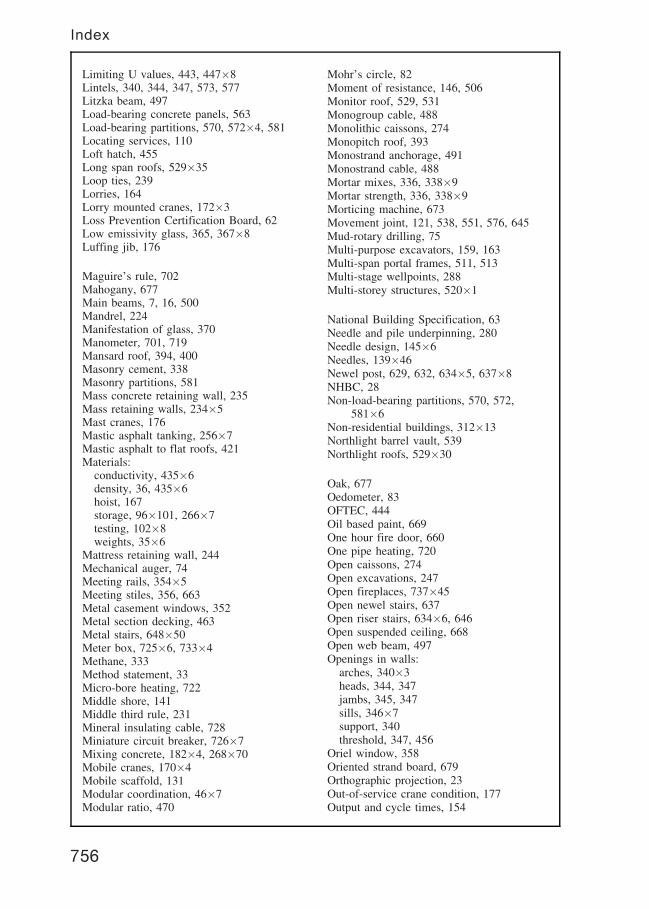
Limiting U values, 443, 447�8Lintels, 340, 344, 347, 573, 577Litzka beam, 497Load-bearing concrete panels, 563Load-bearing partitions, 570, 572�4, 581Locating services, 110Loft hatch, 455Long span roofs, 529�35Loop ties, 239Lorries, 164Lorry mounted cranes, 172�3Loss Prevention Certification Board, 62Low emissivity glass, 365, 367�8Luffing jib, 176
Maguire’s rule, 702Mahogany, 677Main beams, 7, 16, 500Mandrel, 224Manifestation of glass, 370Manometer, 701, 719Mansard roof, 394, 400Masonry cement, 338Masonry partitions, 581Mass concrete retaining wall, 235Mass retaining walls, 234�5Mast cranes, 176Mastic asphalt tanking, 256�7Mastic asphalt to flat roofs, 421Materials:
conductivity, 435�6density, 36, 435�6hoist, 167storage, 96�101, 266�7testing, 102�8weights, 35�6
Mattress retaining wall, 244Mechanical auger, 74Meeting rails, 354�5Meeting stiles, 356, 663Metal casement windows, 352Metal section decking, 463Metal stairs, 648�50Meter box, 725�6, 733�4Methane, 333Method statement, 33Micro-bore heating, 722Middle shore, 141Middle third rule, 231Mineral insulating cable, 728Miniature circuit breaker, 726�7Mixing concrete, 182�4, 268�70Mobile cranes, 170�4Mobile scaffold, 131Modular coordination, 46�7Modular ratio, 470
Mohr’s circle, 82Moment of resistance, 146, 506Monitor roof, 529, 531Monogroup cable, 488Monolithic caissons, 274Monopitch roof, 393Monostrand anchorage, 491Monostrand cable, 488Mortar mixes, 336, 338�9Mortar strength, 336, 338�9Morticing machine, 673Movement joint, 121, 538, 551, 576, 645Mud-rotary drilling, 75Multi-purpose excavators, 159, 163Multi-span portal frames, 511, 513Multi-stage wellpoints, 288Multi-storey structures, 520�1
National Building Specification, 63Needle and pile underpinning, 280Needle design, 145�6Needles, 139�46Newel post, 629, 632, 634�5, 637�8NHBC, 28Non-load-bearing partitions, 570, 572,
581�6Non-residential buildings, 312�13Northlight barrel vault, 539Northlight roofs, 529�30
Oak, 677Oedometer, 83OFTEC, 444Oil based paint, 669One hour fire door, 660One pipe heating, 720Open caissons, 274Open excavations, 247Open fireplaces, 737�45Open newel stairs, 637Open riser stairs, 634�6, 646Open suspended ceiling, 668Open web beam, 497Openings in walls:
arches, 340�3heads, 344, 347jambs, 345, 347sills, 346�7support, 340threshold, 347, 456
Oriel window, 358Oriented strand board, 679Orthographic projection, 23Out-of-service crane condition, 177Output and cycle times, 154
756
Index
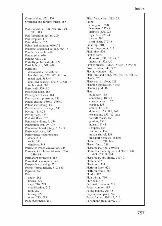
Overcladding, 552, 556Overhead and forklift trucks, 166
Pad foundation, 198, 209, 468, 499,511, 513
Pad foundation design, 200Pad template, 113Paint defects, 672Paints and painting, 669�72Panelled suspended ceiling, 666�7Parallel lay cable, 488Parana pine, 676Parapet wall, 323Partially preformed pile, 224Particle board, 601, 679Partitions:
demountable, 585�6, 581load-bearing, 570, 572, 581�6metal stud, 583�4non-load-bearing, 570, 572, 581�6timber stud, 582
Party wall, 579�80Passenger hoist, 168Passenger vehicles, 164Passive earth pressures, 233Patent glazing, 530�1, 546�7Patent scaffolding, 133Paved areas � drainage, 687Paving, 118�24Paving flags, 124Pedestal floor, 623Pendentive dome, 9, 536Penetration test, 79, 107Percussion bored piling, 213�14Perforated beam, 497Performance requirements:
doors, 373roofs, 391windows, 348
Perimeter trench excavation, 248Permanent exclusion of water, 284,
289�93Permanent formwork, 463Permitted development, 41Perspective drawing, 25Phenol formaldehyde, 517, 680Pigment, 669Pile:
angle, 282beams, 229caps, 216, 229classification, 212root, 282testing, 229types, 213, 218
Piled basements, 251
Piled foundations, 212�29Piling:
contiguous, 290hammers, 227�8helmets, 220, 224rigs, 220, 223�4secant, 290steel sheet, 272�3
Pillar tap, 710Pin or hinge joint, 512Pitch pine, 676Pitched roofs:
domestic, 391, 393�415industrial, 522�30
Pitched trusses, 398�9, 522�3, 529�30Pivot window, 349, 357Placing concrete, 182Plain tiles and tiling, 390, 401�4, 406�7Planer, 673Plank and pot floor, 621Planning application, 41�5Planning grid, 46Plant:
bulldozer, 155concreting, 182�8considerations, 152costing, 153cranes, 170�81dumpers, 165, 185, 262excavators, 159�63, 262forklift trucks, 166graders, 157hoists, 167�8scrapers, 156skimmers, 159tractor shovel, 158transport vehicles, 164�6
Plaster cove, 591, 664Plaster finish, 588Plasterboard, 435, 589�92Plasterboard ceiling, 403, 409�10, 441,
449, 627�8, 664Plasterboard dry lining, 589�91Plasters, 587Plasticiser, 338Platform floor, 628Platform frame, 386Plinths, 317Plug wiring, 730Plywood, 678Pneumatic caisson, 275Poker vibrator, 187Poling boards, 264�5Polyurethane paint, 669Portal frames, 510�13, 516Portsmouth float valve, 710
757
Index

Post-tensioned retaining wall, 241Post-tensioning, 241, 490�1Power circuit, 730�1Power float, 188, 602�3Precast concrete:
diaphragm wall, 292floors, 598�9, 620�2frames, 483�6portal frames, 511�12stairs, 644�7
Preformed concrete pile, 220�1Preservative treatment, 426�7, 429, 517Pressed steel lintels, 344, 347Pressure bulbs, 71�2Prestressed concrete, 252, 344, 487�93Pretensioning, 489Primary elements, 12Primatic cylinder, 712Principal contractor, 49Profile boards, 112�13Profiled surface, 124, 457, 566Program of work, 34Programmer/controller, 723Project co-ordinator, 49Prop design, 146Proportional area method, 439, 441Propped structures, 5, 520Protection orders, 109Public utility services, 110Published Document, 59Pump sizing, 285Purlin fixings, 525�8, 530Purlin roof, 397Purpose designed excavators, 159Purpose made joinery, 674�5Putlog scaffold, 127Putty, 362Pynford stool underpinning, 281
Quarter sawn timber, 515Quarter space landing, 637Quetta bond, 240�1
Radiators, 720�3Radius of gyration, 509Radon, 333Raft basements, 251Raft foundations, 206, 210Rail tracks for cranes, 180Rainscreen cladding, 552, 556Rainwater drainage, 685�7, 690�2Raised access floor, 623Raking shore, 139, 141, 144Raking struts, 142�3, 249Rankine’s formula, 245
Rat trap bond, 309Ready mixed concrete, 271Ready mixed concrete truck, 185, 271Ready mixed mortar, 339Redwood, 676Reinforced concrete:
beams, 464�6column design, 470�1columns, 468�71floors, 463, 615�19formwork, 462, 478�82, 643foundations, 204�6, 208�10lintels, 344pile caps and beams, 216, 229raft foundation, 206, 210reinforcement, 461�86retaining walls, 236slabs, 460�3, 465�7stairs, 639�43strip foundations, 204, 208
Reinforced masonry, 240�1, 310, 577Reinforcement:
bar coding and schedules, 472�3concrete cover, 476�7grip length, 465, 467materials, 474�5spacers, 476spacing, 469types of bar, 474types of mesh, 475
Remedial dpc, 329�30Remote crane control, 178Rendhex box pile, 222Replacement piling, 212�17Residual current device, 727Resin grout, 293Resorcinol formaldehyde, 517, 678Restraint straps, 425, 606�9Retaining walls, 230�46Retaining walls � design, 245�6Retro-ties and studs, 609Reversing drum mixer, 184Ribbed floor, 616�17, 628Rider, 141Ridge detail, 403�4, 409�10, 526, 528, 530Ridge piece, 525�6, 528, 530Ridge roll, 415Ridge tiles, 402�4, 406, 409�10Ridge ventilation, 403�4, 422�4Rigid pavings, 120�1Rigid portal frames, 510�11, 513Ring main wiring, 731Rising damp, 328�31Roads:
construction, 118�21drainage, 688�9
758
Index

earthworks, 119edgings, 122�3footpaths, 122forms, 120gullies, 687�9joints, 121kerbs, 123landscaping, 125pavings, 124services, 125setting out, 118signs, 125
Rolled steel joist, 495Roll over crane skip, 182Roller shutters, 378, 381Roofs and roof covering:
basic forms, 392�4built-up felt, 417�18, 420�1flat top girder, 529, 532garden, 430�1green, 430�1long span, 529�35mastic asphalt, 421monitor, 529, 531northlight, 529�30performance, 391sheet coverings, 524�8shells, 536, 542�4slating, 410�14space deck, 534space frame, 535surface water removal, 682, 686�92thatching, 415thermal insulation, 403�5, 409�10,
417�18, 420�1, 441, 443�4,448�9, 525�8, 530
tiling, 401�4, 406�10timber flat, 392, 416�21timber pitched, 393�400trussed rafter, 399trusses, 398, 523, 529underlay, 401, 403�7, 409�11, 413�14ventilation, 422�4
Rooflights, 394, 529, 531, 546Room sealed appliance, 735Root pile, 282Rotary bored piling, 213, 216�17Rotational dome, 9, 536Rubble chutes and skips, 169Runners, 265
Saddle vault, 540Safe bearing, 200�2, 613Safety signs, 50�1, 125Sampling shells, 74Sand bulking test, 103
Sand compaction, 297Sand pugging, 628Sanitary fittings:
basin, 714bath, 715discharge systems, 717�18shower, 715sink, 714wc pan, 716
Sanitation systems, 717�19Sanitation system testing, 719Sapele, 677Sarking felt, 401Sash weights, 354Saws, 673Scaffolding:
birdcage, 134boards, 127�9cantilever, 136component parts, 126, 132fittings, 132gantry, 138independent, 128ladders, 127�8, 131mobile, 131patent, 133putlog, 127slung, 134suspended, 135truss-out, 137tying-in, 130working platform, 129
Scarf joint, 514Scrapers, 156Screed, 595�6, 604�5Secant piling, 290Secondary beams, 7, 16, 500Secondary elements, 13Secondary glazing, 364Section factor, 505Section modulus, 146, 506SEDBUK, 443Segmental arch, 341Self propelled crane, 171Self supporting static crane, 177�8Separate system, 694, 696Separating wall, 18, 579Services fire stops and seals, 746Setting out:
angles, 113, 117bases, 113basic outline, 111drainage, 700grids, 113levelling, 115�17reduced levels, 114
759
Index

Setting out (continued)roads, 118theodolite, 113, 117trenches, 112
Shear, 463�4, 507, 613Shear bars, 464Shear box, 83Shear leg rig, 74�5, 214Shear plate connector, 533Shear strength of soils, 81�3Shear strength of timber, 613Shear wall structures, 521Sheathed cables, 728Sheet coverings, 524�8Shell roofs, 536, 542�4Shoring, 139�46Short bored pile foundation, 205Shower, 715Shutters, 381Sight rails, 113�14, 118, 700Sills, 346�7, 350�2, 354�9, 366, 368Silt test for sand, 104Simple drainage:
bedding, 700inspection chambers, 693�9jointing, 700roads, 688�9setting out, 700systems, 693�6
Simply supported RC slabs, 460�2Single acting hammer, 227Single barrel vault, 537Single flying shore, 139, 142Single lap tiles and tiling, 408�9Single span portal frames, 510�13, 516Single stack drainage, 717Sink, 714Site:
construction activities, 19electrical supply, 93health and welfare, 95investigations, 67�8, 70, 295layout, 84�6lighting, 90�2materials testing, 102�8offices, 85�6, 94, 99plan, 21, 27, 41preparation, 300�1security, 85, 87setting out, 111�18soil investigations, 68�75storage, 96�101, 266�7survey, 66, 68, 300
Sitka spruce 676Six wheeled grader, 157Sixty minute fire door, 660
Sketches, 22Skimmer, 159Skips, 169Slab base, 501Slates and slating, 410�14Slenderness ratio, 146, 337, 509Sliding doors, 378�80Sliding sash windows, 354�6Slump test, 105Slung scaffold, 134Small diameter piled foundation, 205,
213�16Smoke seal, 661Smoke test, 719Snow loading, 202, 506Soakaway, 692Soakers, 407, 413, 743Socket outlets, 730�1Softwoods, 676Soil:
assessment, 77�83classification, 77�9, 201investigation, 66�75, 295nailing, 243particle size, 77samples, 69stabilization and improvement, 295�9testing, 77�83washing, 301
Solid block walls, 319Solid brick walls, 305�8Solid slab raft, 210Solvent, 669Sound insulating:
floors, 627�8walls, 625�6
Sound insulation, 624�8Sound reduction, 363, 624Space deck, 10, 534Space frame, 10, 535Spindle moulder, 673Spine beam stairs, 646Spiral stair, 641, 647, 649, 653Splice joint, 513Splicing collar, 220�1Split barrel sampler, 79Split load consumer unit, 727Split ring connector, 533Spruce, 676Stack bond, 310Stairs:
alternating tread, 636balusters, 629, 632�5, 638, 641, 647,
649, 651balustrade, 13, 641�2, 647, 649�51formwork, 643
760
Index
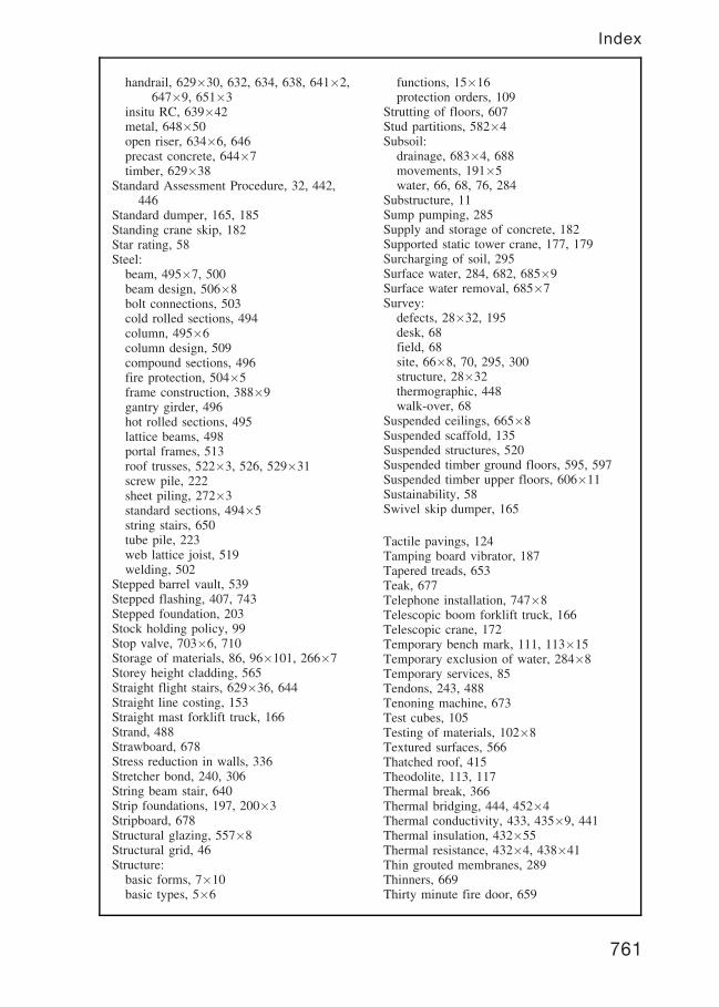
handrail, 629�30, 632, 634, 638, 641�2,647�9, 651�3
insitu RC, 639�42metal, 648�50open riser, 634�6, 646precast concrete, 644�7timber, 629�38
Standard Assessment Procedure, 32, 442,446
Standard dumper, 165, 185Standing crane skip, 182Star rating, 58Steel:
beam, 495�7, 500beam design, 506�8bolt connections, 503cold rolled sections, 494column, 495�6column design, 509compound sections, 496fire protection, 504�5frame construction, 388�9gantry girder, 496hot rolled sections, 495lattice beams, 498portal frames, 513roof trusses, 522�3, 526, 529�31screw pile, 222sheet piling, 272�3standard sections, 494�5string stairs, 650tube pile, 223web lattice joist, 519welding, 502
Stepped barrel vault, 539Stepped flashing, 407, 743Stepped foundation, 203Stock holding policy, 99Stop valve, 703�6, 710Storage of materials, 86, 96�101, 266�7Storey height cladding, 565Straight flight stairs, 629�36, 644Straight line costing, 153Straight mast forklift truck, 166Strand, 488Strawboard, 678Stress reduction in walls, 336Stretcher bond, 240, 306String beam stair, 640Strip foundations, 197, 200�3Stripboard, 678Structural glazing, 557�8Structural grid, 46Structure:
basic forms, 7�10basic types, 5�6
functions, 15�16protection orders, 109
Strutting of floors, 607Stud partitions, 582�4Subsoil:
drainage, 683�4, 688movements, 191�5water, 66, 68, 76, 284
Substructure, 11Sump pumping, 285Supply and storage of concrete, 182Supported static tower crane, 177, 179Surcharging of soil, 295Surface water, 284, 682, 685�9Surface water removal, 685�7Survey:
defects, 28�32, 195desk, 68field, 68site, 66�8, 70, 295, 300structure, 28�32thermographic, 448walk-over, 68
Suspended ceilings, 665�8Suspended scaffold, 135Suspended structures, 520Suspended timber ground floors, 595, 597Suspended timber upper floors, 606�11Sustainability, 58Swivel skip dumper, 165
Tactile pavings, 124Tamping board vibrator, 187Tapered treads, 653Teak, 677Telephone installation, 747�8Telescopic boom forklift truck, 166Telescopic crane, 172Temporary bench mark, 111, 113�15Temporary exclusion of water, 284�8Temporary services, 85Tendons, 243, 488Tenoning machine, 673Test cubes, 105Testing of materials, 102�8Textured surfaces, 566Thatched roof, 415Theodolite, 113, 117Thermal break, 366Thermal bridging, 444, 452�4Thermal conductivity, 433, 435�9, 441Thermal insulation, 432�55Thermal resistance, 432�4, 438�41Thin grouted membranes, 289Thinners, 669Thirty minute fire door, 659
761
Index
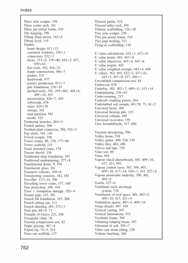
Three axle scraper, 156Three centre arch, 341Three pin portal frame, 510Tile hanging, 390Tilting drum mixer, 183�4Tilting level, 115Timber:
beam design, 611�13casement windows, 350�1connectors, 532�3doors, 373�6, 379�80, 654�5, 657,
659�62flat roofs, 392, 416�21frame construction, 386�7girders, 532hardwoods, 677joinery production, 673�7pile foundation, 218�19pitched roofs, 391, 393�401, 404�6,
409�10, 425preservation, 426�7, 429softwoods, 676stairs, 629�38storage, 101stud partition, 582trestle, 223
Timbering trenches, 264�5Tooled surface, 566Toothed plate connector, 398, 532�3Top shore, 141, 144Towed scraper, 156Tower cranes, 86, 170, 177�80Tower scaffold, 131Track mounted crane, 174Tractor shovel, 158Traditional strip foundation, 197Traditional underpinning, 277�8Translational dome, 9, 536Translucent glass, 361Transport vehicles, 164�6Transporting concrete, 182, 185Traveller, 112�14, 700Travelling tower crane, 177, 180Tree protection, 109, 194Trees � foundation damage, 192�4Tremie pipe, 215, 291Trench fill foundation, 197, 208Trench setting out, 112Trench sheeting, 265, 272�3Trial pits, 68�9, 73Triangle of forces, 231, 246Triangular chart, 78Triaxial compression test, 82Triple glazing, 367�8Tripod rig, 74�5, 214Truss out scaffold, 137
Trussed purlin, 518Trussed rafter roof, 399Tubular scaffolding, 126�38Two axle scraper, 156Two pin portal frame, 510Two pipe heating, 721Tying-in scaffolding, 130
U value calculations, 432�3, 437�41U value limits, 443, 447�8U value objectives, 443�4, 447�8U value targets, 443U value weighted average, 443�4, 448U values, 363, 365, 432�3, 437�41,
443�5, 447�8, 527, 450�1Unconfined compression test, 81Undercoat, 670Underlay, 401, 403�7, 409�11, 413�14Underpinning, 276�83Under-reaming, 217Undersill cladding panels, 564Undisturbed soil sample, 69�70, 73, 81�2Universal beam, 495Universal bearing pile, 222Universal column, 495Universal excavator, 159Urea formaldehyde, 517, 680
Vacuum dewatering, 594Valley beam, 530Valley gutter, 409, 528, 530Valley tiles, 402, 406Valves and taps, 710Vane test, 80Vans, 164Vapour check plasterboard, 403, 409�10,
417, 421, 592Vapour control layer, 387, 389, 403,
409�10, 417�18, 420�1, 431, 527�8Vapour permeable underlay, 390, 401,
404�5Vaults, 537�9Ventilated stack discharge
system, 718Ventilation of roof space, 401, 403�5,
409�10, 417, 421�4Ventilation spacer, 403�4, 409�10Verge details, 407, 418Vertical casting, 567Vertical laminations, 515Vestibule frame, 369Vibrating tamping beam, 187Vibration of soil, 295�7Vibro cast insitu piling, 226Volume batching, 268
762
Index
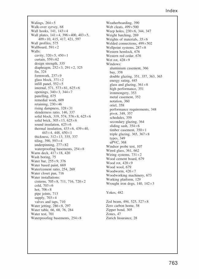
Walings, 264�5Walk-over syrvey, 68Wall hooks, 141, 143�4Wall plates, 141�4, 396�400, 403�5,
409�10, 415, 417, 421, 597Wall profiles, 575Wallboard, 591�2Walls:
cavity, 320�5, 450�1curtain, 559�62design strength, 335diaphragm, 252�3, 291�2, 325fin, 324formwork, 237�9glass block, 371�2infill panel, 552�5internal, 571, 573�81, 625�6openings, 340�3, 344�7panelling, 675remedial work, 609retaining, 230�46rising dampness, 328�31slenderness ratio, 146, 337solid block, 319, 574, 576�8, 625�6solid brick, 305�13, 625�6sound insulation, 625�6thermal insulation, 433�6, 439�40,
443�4, 448, 450�1thickness, 312�13, 335, 337tiling, 390, 593�4underpinning, 277�82waterproofing basements, 254�8
Warm deck, 417�18, 420Wash boring, 75Water bar, 255�9, 376Water based paint, 669Water/cement ratio, 254, 269Water closet pan, 716Water installations:
cisterns, 705�8, 711, 716, 720�2cold, 703�6hot, 706�8pipe joints, 713supply, 703�4valves and taps, 710
Water jetting, 286�8, 297Water table, 66, 68, 76, 284Water test, 701Waterproofing basements, 254�8
Weatherboarding, 390Web cleats, 499�500Weep holes, 230�6, 344, 347Weight batching, 269Weights of materials, 35�6Welded connections, 499�502Wellpoint systems, 287�8Western hemlock, 676Western red cedar, 676Wet rot, 428�9Windows:
aluminium casement, 366bay, 358double glazing, 351, 357, 363, 365energy rating, 445glass and glazing, 361�8high performance, 351ironmongery, 353metal casement, 352notation, 360oriel, 358performance requirements, 348pivot, 349, 357schedules, 359secondary glazing, 364sliding sash, 354�6timber casement, 350�1triple glazing, 365, 367�8types, 349uPVC, 368
Windsor probe test, 107Wired glass, 361, 662Wiring systems, 731�2Wood cement board, 679Wood rot, 428�9Wood wool, 679Woodworm, 426�7Woodworking machinery, 673Working platform, 129Wrought iron dogs, 140, 142�3
Yokes, 482
Zed beam, 494, 525, 527�8Zero carbon home, 58Zipper bond, 305Zones, 47Zurich Insurance, 28
763
Index


![Construction Handbook[1]](https://img.pdfslide.us/doc/110x75/577cc6881a28aba7119e883b/construction-handbook1.jpg)