Embed Size (px)
Citation preview
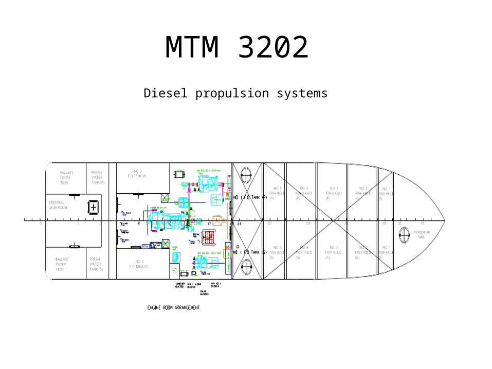
MTM 3202 Diesel propulsion systems
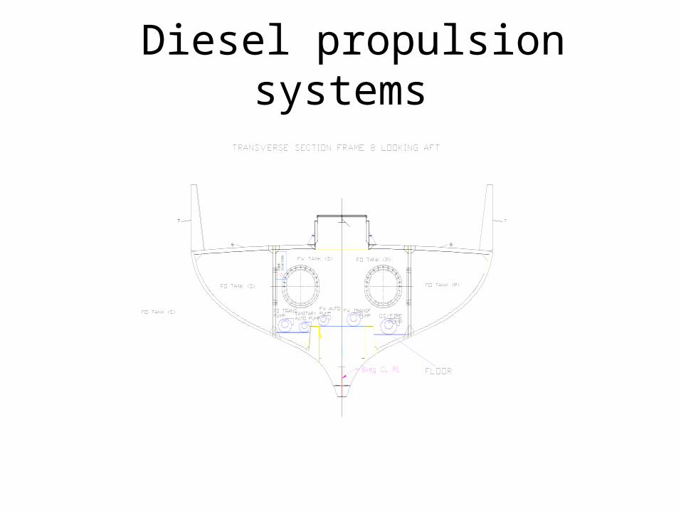
Diesel propulsion systems
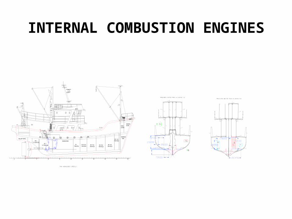
INTERNAL COMBUSTION ENGINES
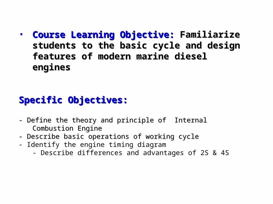
• Course Learning Objective: Course Learning Objective: Familiarize Familiarize students to the basic cycle and design features students to the basic cycle and design features of modern marine diesel enginesof modern marine diesel engines
Specific Objectives:Specific Objectives:
- Define the theory and principle of Internal Combustion Engine- Define the theory and principle of Internal Combustion Engine - Describe basic operations of working cycle- Describe basic operations of working cycle- Identify the engine timing diagram
- Describe differences and advantages of 2S & 4S
Principle of I.C.E
• An internal combustion engine is one in which the fuel is burnt within the engine -> usually of the reciprocating type.
• It involve system where combustion of the fuel and the conversion of the heat energy from combustion to mechanical energy takes place within the cylinders (ICE)
I.C.E. CATEGORIES
– Spark ignition engines use gaseous or volatile distillate fuels -> work on a modified Otto cycle -> operate on the 2 or 4 – stroke cycle.
– Compression ignition engine use distillate liquid fuels -> work on either 2 or 4 – stroke cycle and normally designed to operate on the dual-combustion cycle (Otto and Diesel cycle)
Otto cycle
• In the Otto cycle the theoretical pressure –volume diagram is formed from : two constant – volume and two adiabatic processes.
• The air in the cylinder is compressed adiabatically.
• Heat is added to the air at constant volume -> Work is done during the adiabatic expansion and -> then heat is rejected at constant volume
Otto Cycle
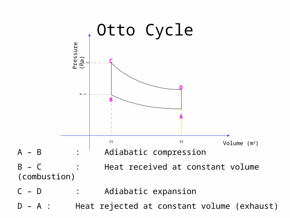
A – B : Adiabatic compression
B – C : Heat received at constant volume (combustion)
C – D : Adiabatic expansion
D – A : Heat rejected at constant volume (exhaust)
Pre
ssure
(P
a)
Volume (m3)V1 V2
P 1P 2
A
B
C
D
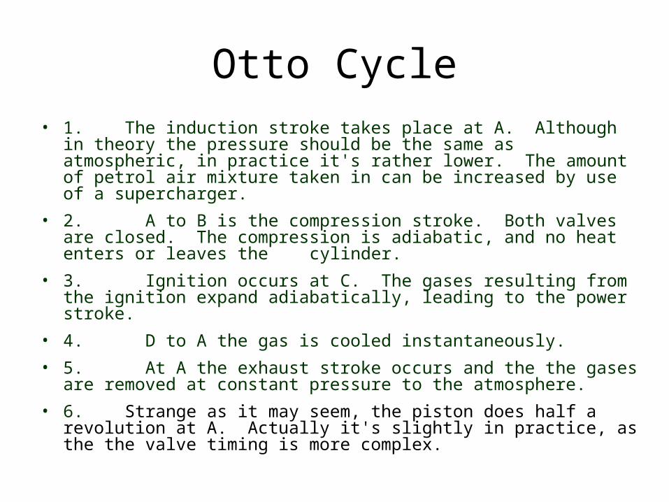
Otto Cycle• 1. The induction stroke takes place at A. Although in
theory the pressure should be the same as atmospheric, in practice it's rather lower. The amount of petrol air mixture taken in can be increased by use of a supercharger.
• 2. A to B is the compression stroke. Both valves are closed. The compression is adiabatic, and no heat enters or leaves the cylinder.
• 3. Ignition occurs at C. The gases resulting from the ignition expand adiabatically, leading to the power stroke.
• 4. D to A the gas is cooled instantaneously.
• 5. At A the exhaust stroke occurs and the the gases are removed at constant pressure to the atmosphere.
• 6. Strange as it may seem, the piston does half a revolution at A. Actually it's slightly in practice, as the the valve timing is more complex.
Diesel cycle
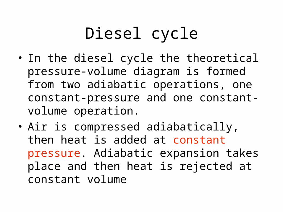
• In the diesel cycle the theoretical pressure-volume diagram is formed from two adiabatic operations, one constant-pressure and one constant-volume operation.
• Air is compressed adiabatically, then heat is added at constant pressure. Adiabatic expansion takes place and then heat is rejected at constant volume
Diesel Cycle
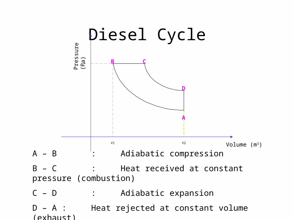
A – B : Adiabatic compression
B – C : Heat received at constant pressure (combustion)
C – D : Adiabatic expansion
D – A : Heat rejected at constant volume (exhaust)
Pre
ssure
(P
a)
Volume (m3)V1 V2
P
A
B C
D
Diesel cycle
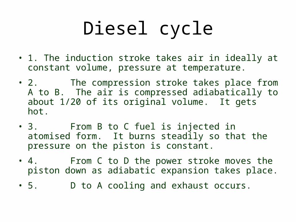
• 1. The induction stroke takes air in ideally at constant volume, pressure at temperature.
• 2. The compression stroke takes place from A to B. The air is compressed adiabatically to about 1/20 of its original volume. It gets hot.
• 3. From B to C fuel is injected in atomised form. It burns steadily so that the pressure on the piston is constant.
• 4. From C to D the power stroke moves the piston down as adiabatic expansion takes place.
• 5. D to A cooling and exhaust occurs.
Dual cycle
• In the dual cycle, air is compressed adiabatically, then heat is added, partly in a constant volume process and the remainder in a constant pressure process.
• Expansion takes place adiabatically and then heat is rejected at constant volume
Pre
ssure
(P
a)
Volume (m3)V1 V2
P
A
B
C D
E
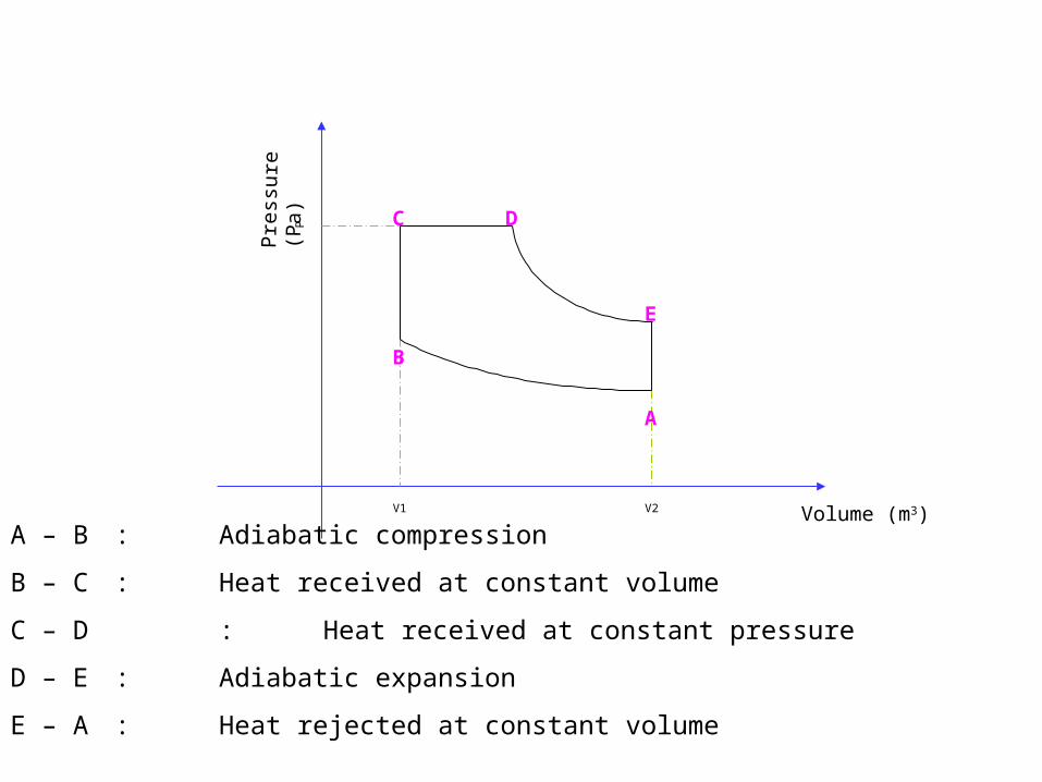
A – B : Adiabatic compression
B – C : Heat received at constant volume
C – D : Heat received at constant pressure
D – E : Adiabatic expansion
E – A : Heat rejected at constant volume
COMPRESSION IGNITION ENGINE
• Compression ignition engine works on dual cycle
• The fresh air enters each of the engine cylinders and is compressed by the upward movement of the piston.
• The compression causes the temperature and pressure of the fresh air to increase
• Fuel injectors or fuel valve will supply the fuel oil in fine spray when the piston is nearly at top dead centre
• The fuel will then be mixed with air (compressed) and burn inside the cylinder when the piston is at TDC.
• The expanding gases on top of the piston (completed combustion) will push the piston moving it downward and rotating the crankshaft .
• The cycle will be repeated until the engine stops
Cycle of Operations
• Four strokes of CI engine are as follows:-– Suction Stroke / Induction Stroke
– Compression Stroke
– Explosion Stroke / Power Stroke
– Exhaust Stroke
SUCTION STROKE
• In which the air is admitted to the engine cylinder
COMPRESSION STROKE
• In which the charge of fresh air is compressed by the piston, and fuel is injected just before the point of maximum compression
POWER STROKE
• In which the air- fuel mixture is ignited by the heat produced by compression of air
• The pressure rises due to fuel combustion and pushes piston downwards to drive the engine
EXHAUST STROKE
• Exhaust valve opens at the end of power stroke
• The expanded burnt gases are exhausted / expelled from the cylinder
• The four strokes in duel cycle of CI engine are completed in two revolutions of the crankshaft.
• There are thus two piston strokes in each revolution of the crankshaft
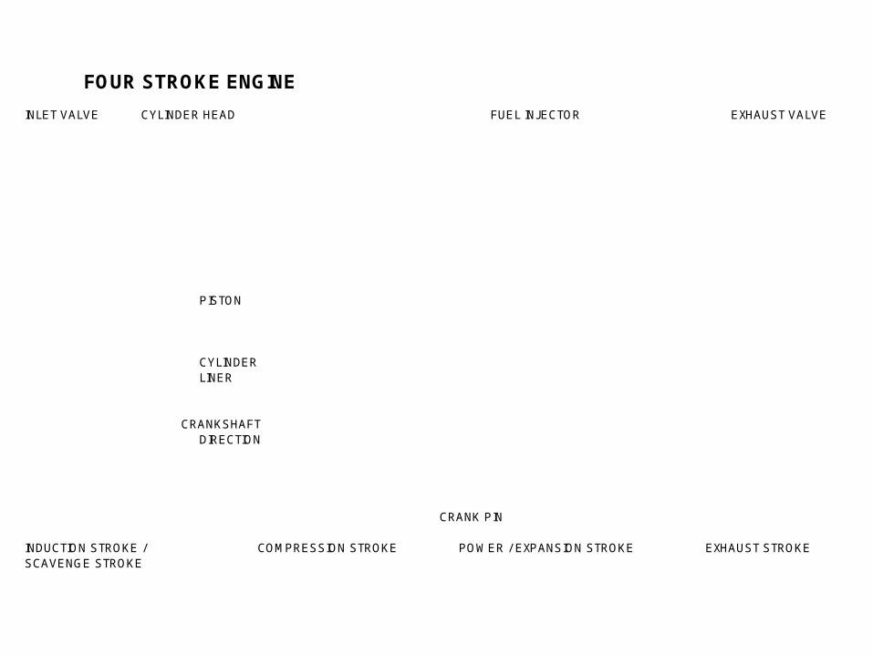
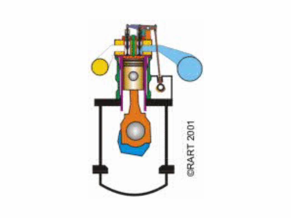
FOUR STROKE ENGINE
INLET VALVE CYLINDER HEAD FUEL INJECTOR
PISTON
CYLINDERLINER
CRANKSHAFT DIRECTION
CRANK PIN
INDUCTION STROKE / COMPRESSION STROKESCAVENGE STROKE
POWER / EXPANSION STROKE EXHAUST STROKE
EXHAUST VALVE
EXHAUST STROKE
How strokes are executed
• Strokes are executed by combination of valves and gears
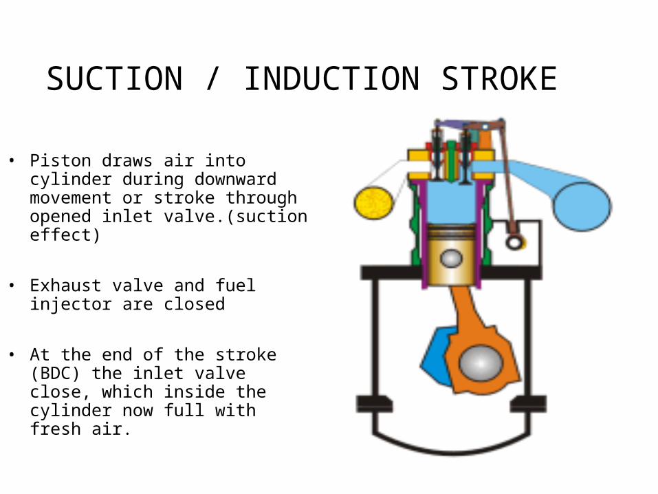
SUCTION / INDUCTION STROKE
• Piston draws air into cylinder during downward movement or stroke through opened inlet valve.(suction effect)
• Exhaust valve and fuel injector are closed
• At the end of the stroke (BDC) the inlet valve close, which inside the cylinder now full with fresh air.
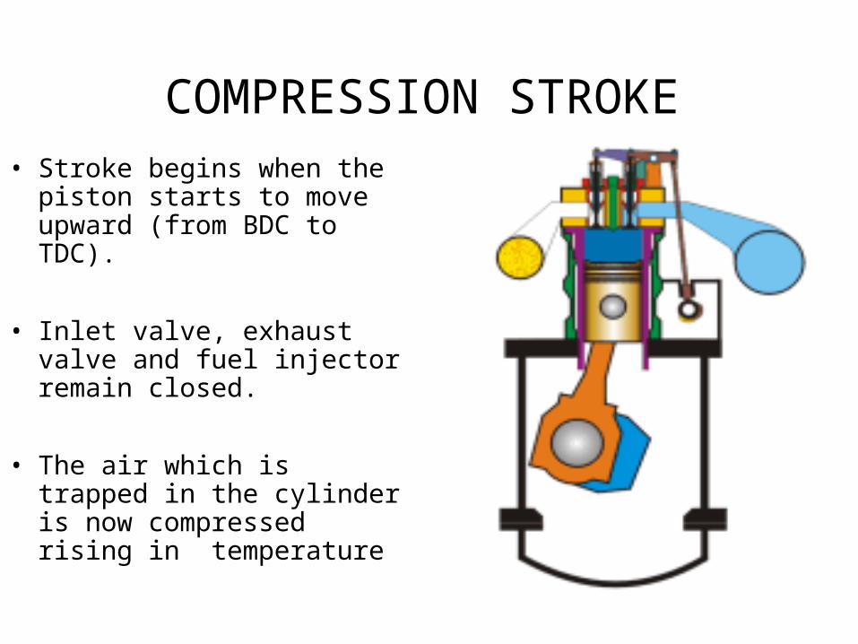
COMPRESSION STROKE• Stroke begins when the
piston starts to move upward (from BDC to TDC).
• Inlet valve, exhaust valve and fuel injector remain closed.
• The air which is trapped in the cylinder is now compressed rising in temperature
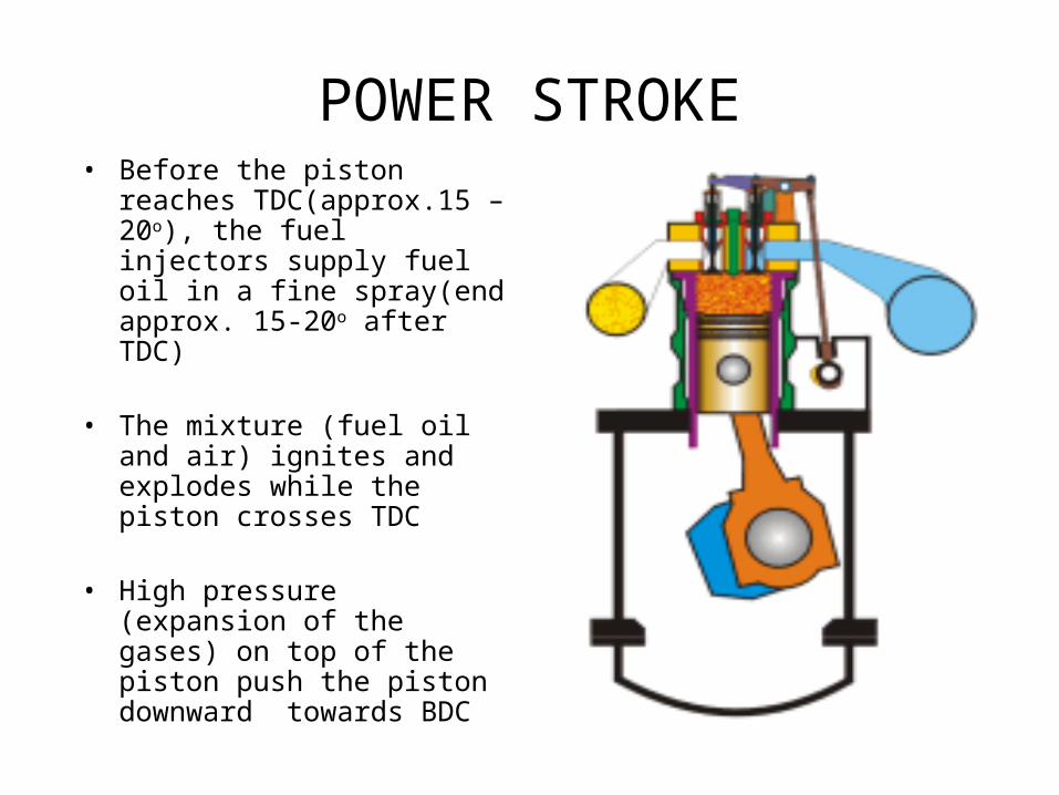
POWER STROKE• Before the piston reaches
TDC(approx.15 – 20o), the fuel injectors supply fuel oil in a fine spray(end approx. 15-20o after TDC)
• The mixture (fuel oil and air) ignites and explodes while the piston crosses TDC
• High pressure (expansion of the gases) on top of the piston push the piston downward towards BDC
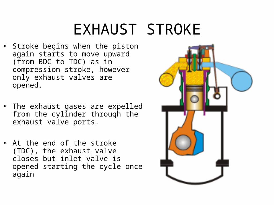
EXHAUST STROKE• Stroke begins when the piston again
starts to move upward (from BDC to TDC) as in compression stroke, however only exhaust valves are opened.
• The exhaust gases are expelled from the cylinder through the exhaust valve ports.
• At the end of the stroke (TDC), the exhaust valve closes but inlet valve is opened starting the cycle once again
Power produced
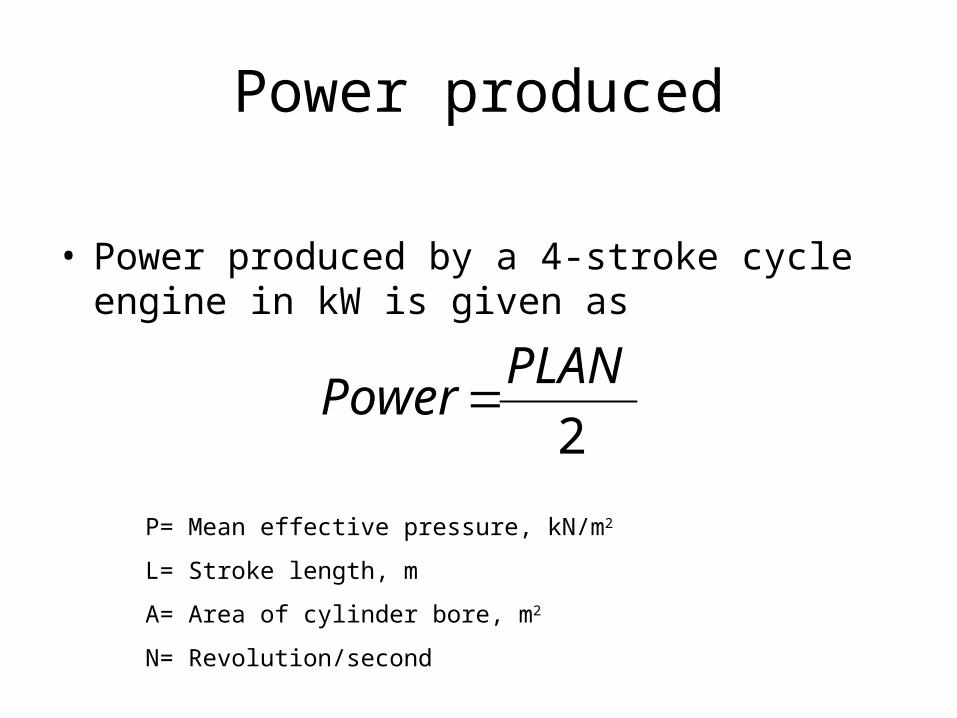
• Power produced by a 4-stroke cycle engine in kW is given as
2
PLANPower
P= Mean effective pressure, kN/m2
L= Stroke length, m
A= Area of cylinder bore, m2
N= Revolution/second
4 - STROKE CYCLE
1
7
1
2
3 4 5
6
8
9
10
PRESSURE
DIRECTIONPIS
TO
N P
OSIT
ION
1/7
2
3 45
6
8910
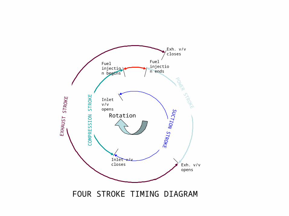
Timing Diagram
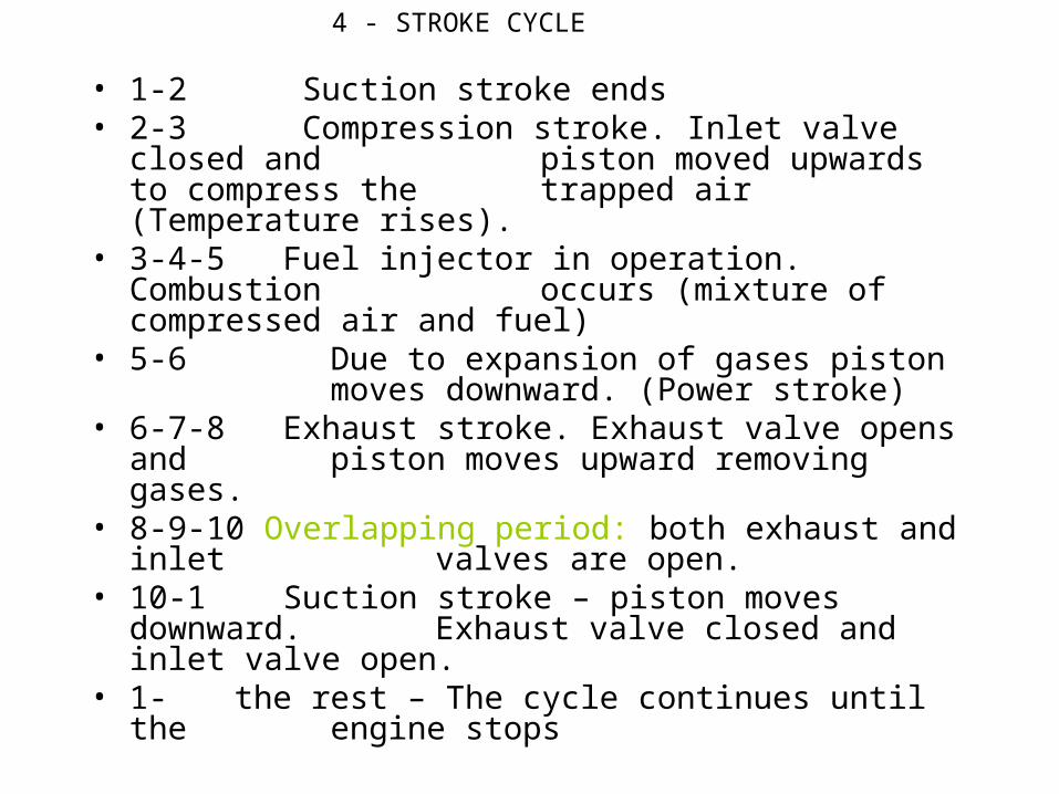
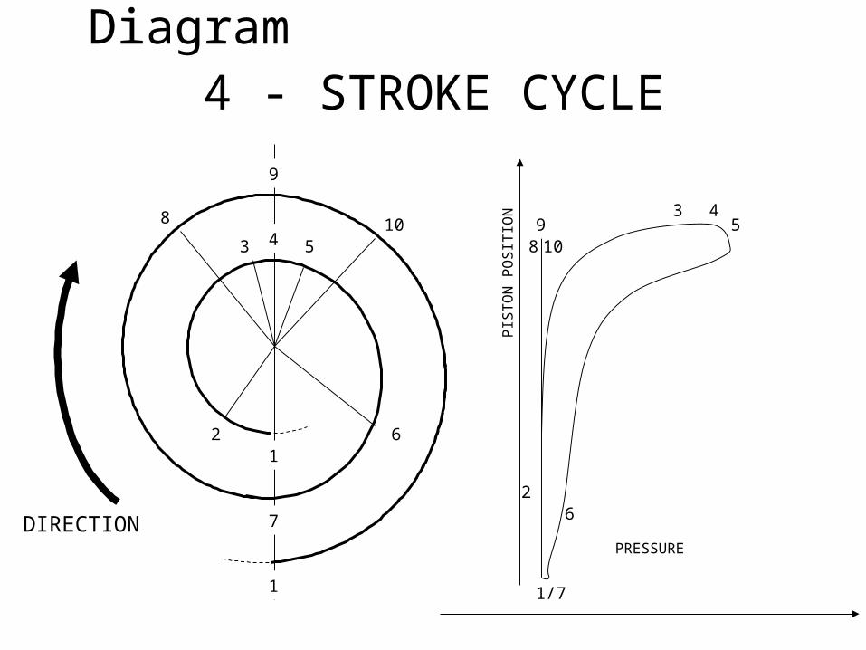
• 1-2 Suction stroke ends• 2-3 Compression stroke. Inlet valve closed and
piston moved upwards to compress the trapped air (Temperature rises).
• 3-4-5 Fuel injector in operation. Combustion occurs (mixture of compressed air and fuel)
• 5-6 Due to expansion of gases piston moves downward. (Power stroke)
• 6-7-8 Exhaust stroke. Exhaust valve opens and piston moves upward removing gases.
• 8-9-10 Overlapping period: both exhaust and inlet valves are open.
• 10-1 Suction stroke – piston moves downward. Exhaust valve closed and inlet valve open.
• 1- the rest – The cycle continues until the engine stops
4 - STROKE CYCLE
RotationSU
CTIO
N S
TR
OK
ECO
MPR
ESSIO
N S
TR
OK
E
POW
ER STR
OKE
EX
HA
UST S
TR
OK
E
Exh. v/v opens
Inlet v/v closes
Inlet v/v opens
Fuel injection begins
Fuel injection ends
Exh. v/v closes
FOUR STROKE TIMING DIAGRAM
VALVE OVERLAPPINGIt can be defined as the period when inlet and exhaust
valve were open at the same time.E.g.,• Inlet valve opened before the piston reached TDC at
the end of exhaust stroke, say 20o before TDC.• Exhaust valve remained open and will be closed at
certain degree of the piston movement after TDC, say 20o after TDC.
• By providing overlapping period on 4 – stroke engine, the residual exhaust gases will be expelled effectively with the rushing in of fresh air.
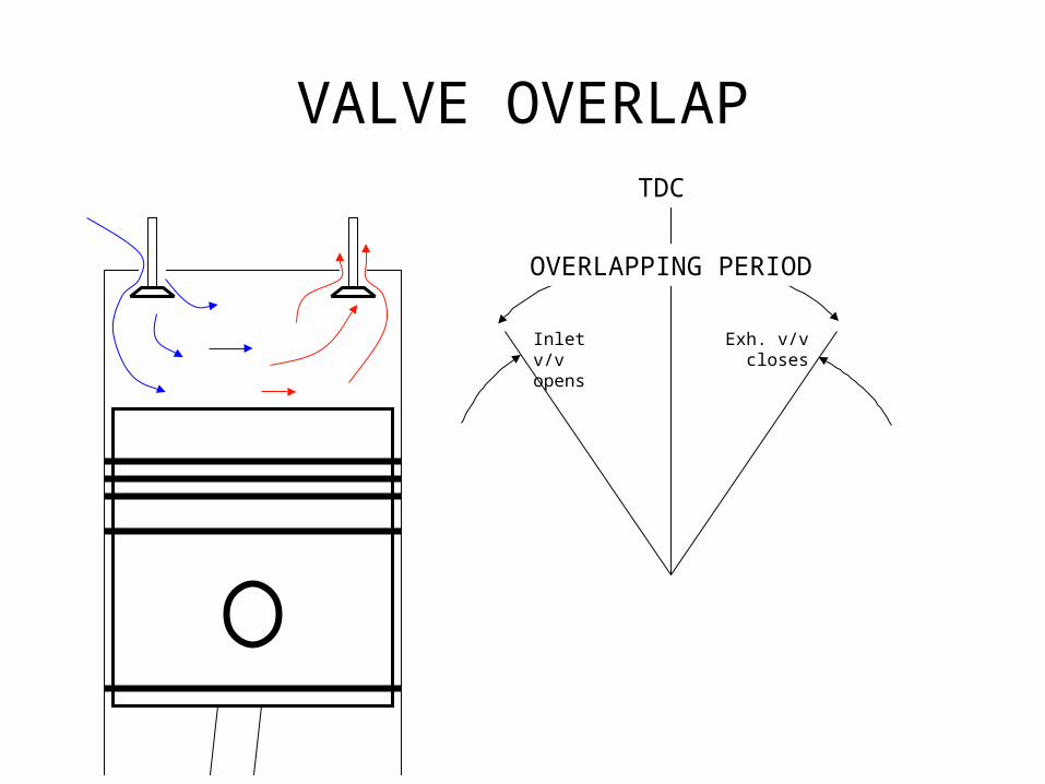
VALVE OVERLAP
OVERLAPPING PERIOD
Inlet v/v opens
Exh. v/v closes
TDC
2-Stroke cycle diesel engines
• Learning Objective: Learning Objective: Know the basic cycle Know the basic cycle and design features of modern marine diesel and design features of modern marine diesel enginesengines
Specific Objectives:Specific Objectives: • Describe the operation cycle process of a 2-stroke diesel engine.• Identify the 2-stroke engine timing diagram
• The two stroke cycle is so called because it takes two strokes of the piston or one revolution of crank shaft to complete the processes needed to convert the energy in the fuel into work.
TWO STROKE CYCLE
Why 2-Stroke Cycle Engines
• We know 4-stroke cycle engine gives only one power stroke out of 4 strokes of the piston or one power stroke in two revolutions of the crank shaft.
• This makes engine’s power to weight ratio low mainly because three strokes consume power against one which produces
2S
• In the two stroke engine, cycle is completed in two strokes of the piston or one revolution of the crankshaft.
• Thus out of 3 power consuming strokes of the 4-stroke cycle two strokes are saved
• Engine thus produces one power stroke in every revolution of the engine which is two times in comparison to 4-stroke cycle
• This improves power to weight ratio of the engine and reduces its size for same power.
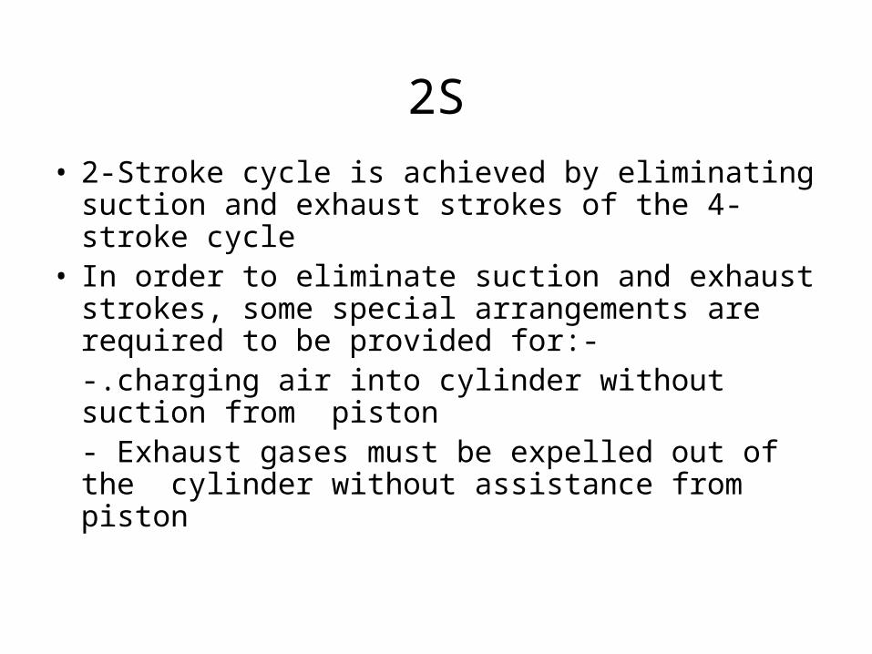
• 2-Stroke cycle is achieved by eliminating suction and exhaust strokes of the 4-stroke cycle
• In order to eliminate suction and exhaust strokes, some special arrangements are required to be provided for:--.charging air into cylinder without suction from piston- Exhaust gases must be expelled out of the cylinder without assistance from piston
2S
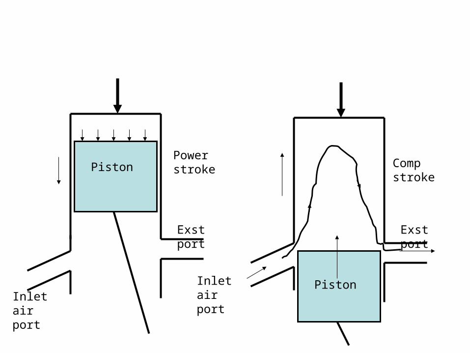
Inlet air port
Exst portExst port
Power stroke Comp
strokePiston
PistonInlet air port
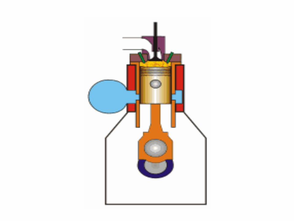
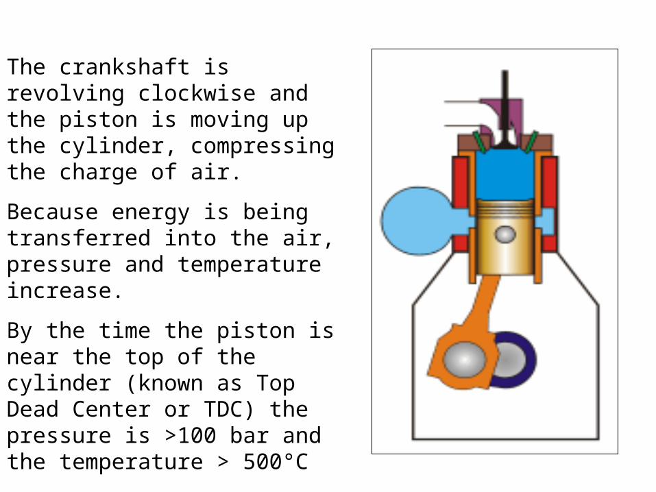
The crankshaft is revolving clockwise and the piston is moving up the cylinder, compressing the charge of air.
Because energy is being transferred into the air, pressure and temperature increase.
By the time the piston is near the top of the cylinder (known as Top Dead Center or TDC) the pressure is >100 bar and the temperature > 500°C
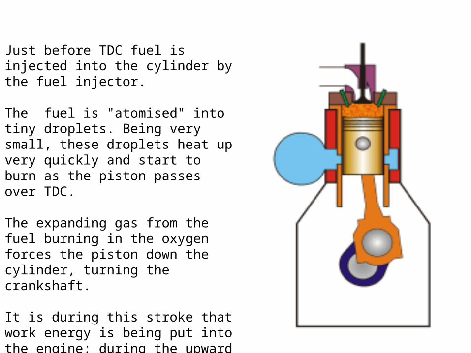
Just before TDC fuel is injected into the cylinder by the fuel injector.
The fuel is "atomised" into tiny droplets. Being very small, these droplets heat up very quickly and start to burn as the piston passes over TDC.
The expanding gas from the fuel burning in the oxygen forces the piston down the cylinder, turning the crankshaft.
It is during this stroke that work energy is being put into the engine; during the upward stroke of the piston, the engine is having to do the work.
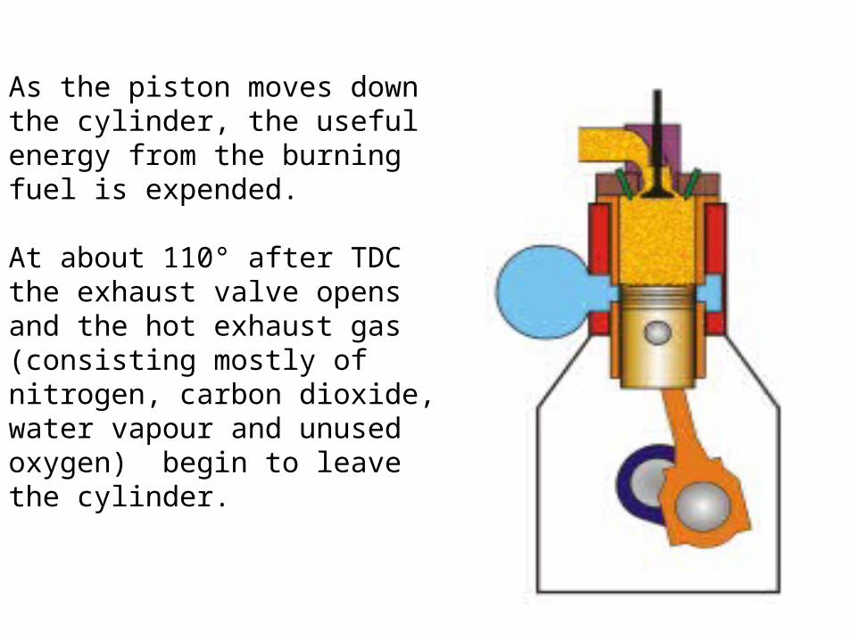
As the piston moves down the cylinder, the useful energy from the burning fuel is expended.
At about 110° after TDC the exhaust valve opens and the hot exhaust gas (consisting mostly of nitrogen, carbon dioxide, water vapour and unused oxygen) begin to leave the cylinder.
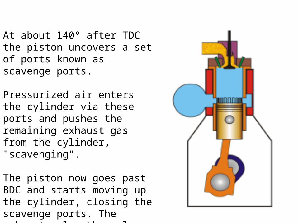
At about 140º after TDC the piston uncovers a set of ports known as scavenge ports.
Pressurized air enters the cylinder via these ports and pushes the remaining exhaust gas from the cylinder, "scavenging".
The piston now goes past BDC and starts moving up the cylinder, closing the scavenge ports. The exhaust valve then closes and compression begins.
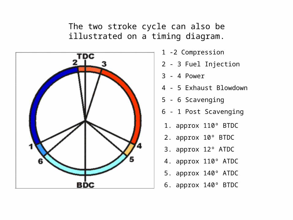
1 -2 Compression
2 - 3 Fuel Injection
3 - 4 Power
4 - 5 Exhaust Blowdown
5 - 6 Scavenging
6 - 1 Post Scavenging
1. approx 110º BTDC
2. approx 10º BTDC
3. approx 12º ATDC
4. approx 110º ATDC
5. approx 140º ATDC
6. approx 140º BTDC
The two stroke cycle can also be illustrated on a timing diagram.
1
2
3
4 5 6
7
8PIS
TO
N P
OSIT
ION
PRESSURE1
2
3
4 5
6
7
8
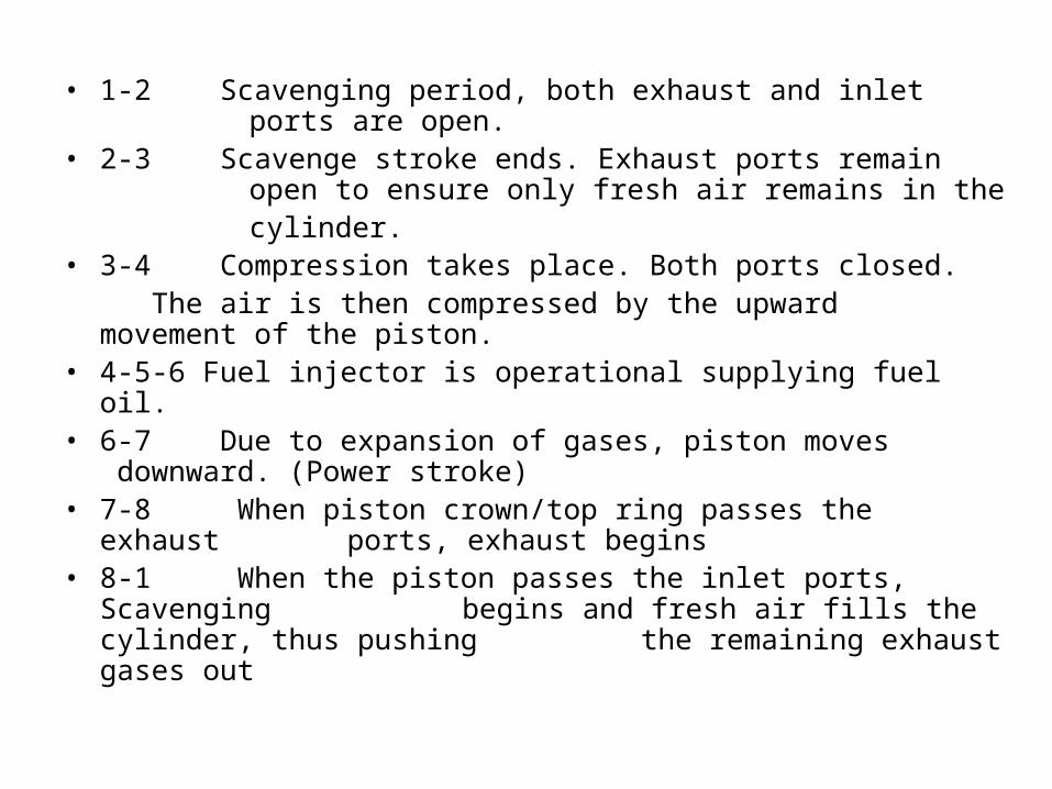
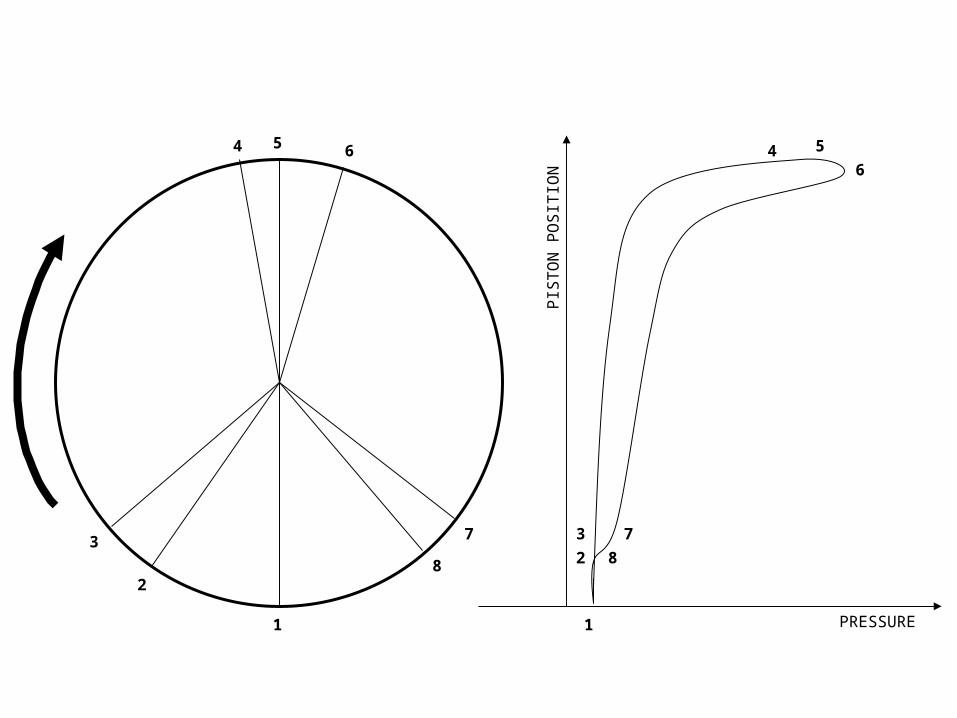
• 1-2 Scavenging period, both exhaust and inlet ports are open.
• 2-3 Scavenge stroke ends. Exhaust ports remain open to ensure only fresh air remains in the
cylinder.• 3-4 Compression takes place. Both ports closed.
The air is then compressed by the upward movement of the piston.
• 4-5-6 Fuel injector is operational supplying fuel oil.• 6-7 Due to expansion of gases, piston moves
downward. (Power stroke)• 7-8 When piston crown/top ring passes the exhaust
ports, exhaust begins • 8-1 When the piston passes the inlet ports, Scavenging
begins and fresh air fills the cylinder, thus pushing the remaining exhaust gases out
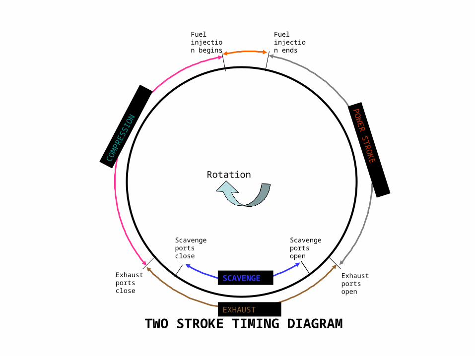
Rotation
Fuel injection begins
Fuel injection ends
SCAVENGE
CO
MPR
ESSI
ON
POW
ER
STR
OKE
EXHAUST
Scavenge ports open
Scavenge ports close
Exhaust ports open
Exhaust ports close
TWO STROKE TIMING DIAGRAM
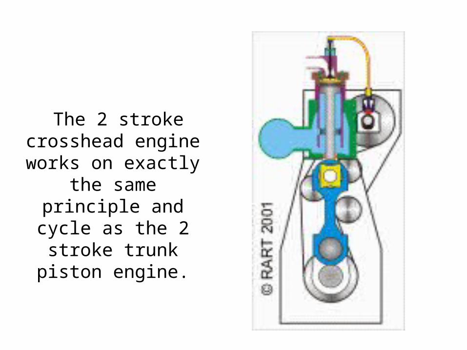
The 2 stroke crosshead engine works on exactly
the same principle and cycle as the 2 stroke trunk piston
engine.
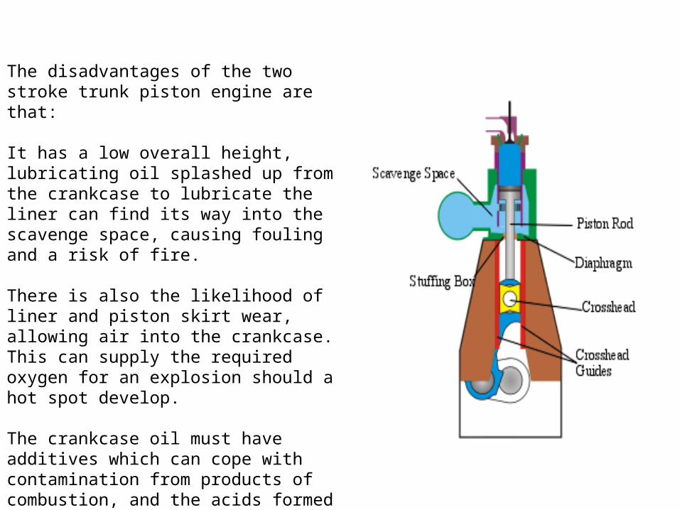
The disadvantages of the two stroke trunk piston engine are that:
It has a low overall height, lubricating oil splashed up from the crankcase to lubricate the liner can find its way into the scavenge space, causing fouling and a risk of fire.
There is also the likelihood of liner and piston skirt wear, allowing air into the crankcase. This can supply the required oxygen for an explosion should a hot spot develop.
The crankcase oil must have additives which can cope with contamination from products of combustion, and the acids formed during combustion due to the sulphur in the fuel.
The majority of 2 stroke engines encountered at sea are of the "crosshead" type. In this type of engine the combustion space (formed by the cylinder liner, piston and cylinder head), and the scavenge space are separated from the crankcase by the diaphragm plate.
The piston rod is bolted to the piston and passes through a stuffing box mounted in the diaphragm plate. The stuffing box provides a seal between the two spaces, stopping oil from being carried up to the scavenge space, and scavenge air leaking into the crankcase.
The foot of the piston rod is bolted to the crosshead pin. The top end of the connecting rod swings about the crosshead pin, as the downward load from the expanding gas applies a turning force to the crankshaft.
To ensure that the crosshead reciprocates in alignment with the piston in the cylinder, guide shoes are attached either side of the crosshead pin. These shoes are lined with white metal, a bearing material and they reciprocate against the crosshead guides, which are bolted to the frame of the engine. The crosshead guides are located in-between each cylinder.
Using the crosshead design of engine allows engines to be built with very long strokes - which means the engine can burn a greater quantity of fuel/stroke and develop more power. The fuel used can be of a lower grade than that used in a trunk piston engine, with a higher sulphur content, whilst high alkalinity cylinder oils with a different specification to that of the crankcase oil are used to lubricate the cylinder liner and piston rings and combat the effects of acid attack.
SCAVENGING
• To ensure a sufficient supply of fresh air for combustion by removing all remaining exhaust gases by blowing with these fresh air.
• Supercharging is a large mass of air that is supplied to the cylinder by blowing it in under pressure either by electrically driven auxiliary blower or exhaust gas driven turbocharger.
• The flow path of the scavenge air is decided by the engine port shape and design and the exhaust arrangements.
SCAVENGING PERIOD
It can be defined as a period when inlet and exhaust are open at the same time:
• Remaining exhaust gas will be expelled from the cylinder through exhaust ports or exhaust valve (if fitted).
• Fresh air which has collected in the scavenge manifold rush into the cylinder
• Scavenging period: Normally when piston is at BDC, (or as per maker or engine design or the location of the ports itself)

SCAVENGING METHODS• CROSS/DIRECT – FLOW SCAVENGING
• LOOP SCAVENGING
• UNIFLOW SCAVENGING
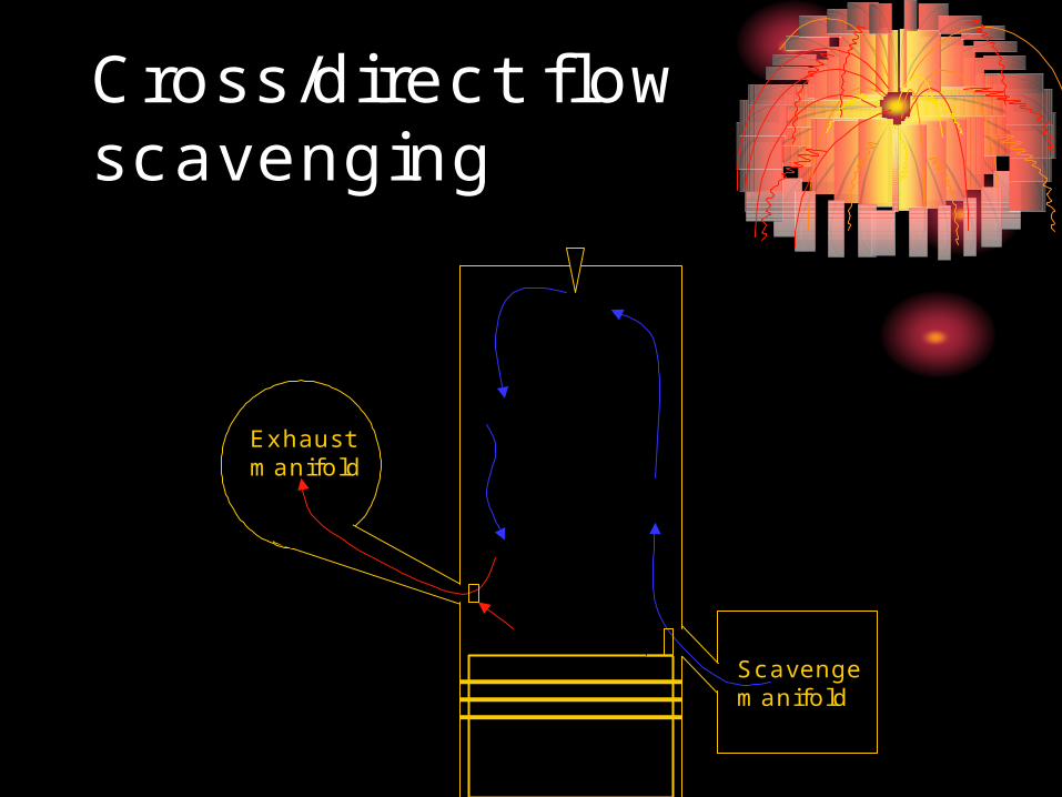
Cross/direct flow scavenging
Exhaust manifold
Scavenge manifold
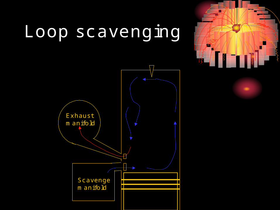
Loop scavenging
Exhaust manifold
Scavenge manifold
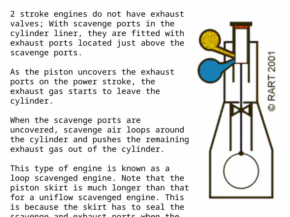
2 stroke engines do not have exhaust valves; With scavenge ports in the cylinder liner, they are fitted with exhaust ports located just above the scavenge ports.
As the piston uncovers the exhaust ports on the power stroke, the exhaust gas starts to leave the cylinder.
When the scavenge ports are uncovered, scavenge air loops around the cylinder and pushes the remaining exhaust gas out of the cylinder.
This type of engine is known as a loop scavenged engine. Note that the piston skirt is much longer than that for a uniflow scavenged engine. This is because the skirt has to seal the scavenge and exhaust ports when the piston is at TDC.
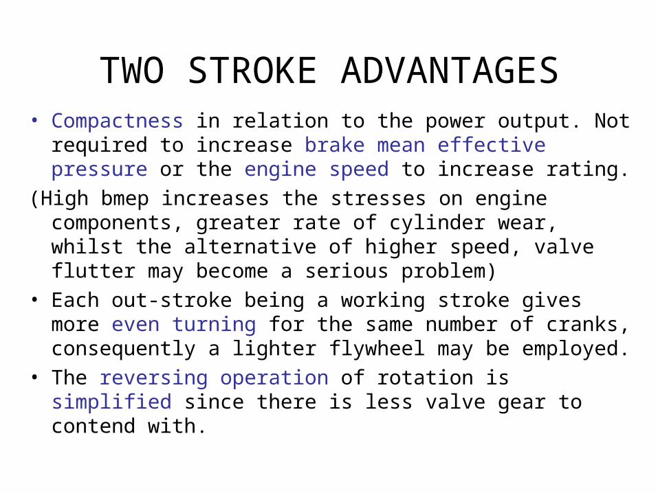
TWO STROKE ADVANTAGES• Compactness in relation to the power output. Not required
to increase brake mean effective pressure or the engine speed to increase rating.
(High bmep increases the stresses on engine components, greater rate of cylinder wear, whilst the alternative of higher speed, valve flutter may become a serious problem)
• Each out-stroke being a working stroke gives more even turning for the same number of cranks, consequently a lighter flywheel may be employed.
• The reversing operation of rotation is simplified since there is less valve gear to contend with.
OTHER ADVANTAGES
• Fewer moving parts and lower maintenance• Lower specific fuel consumption• No gear loss• Simplicity in construction• Longer life time• Higher reliability (product)• Low lubricating oil consumption• Better ability to burn low quality fuel oil
• Good volumetric efficiency, good combustion characteristic and positive exhaust scavenging.
• The thermal and mechanical efficiencies are slightly better than 2S engine.
• Only half the quantity of the heat generated in the cylinders has to be dealt within a given time, so that efficient lubrication of the piston and cooling of the cylinder is more easily accomplished.
FOUR STROKE ADVANTAGES
• Lower initial cost for equivalent power
• Ease of installation
• Lower weight per unit power
• Saving in weight and engine room length
• Increased cargo capacity
• Free choice of propeller speed through gearing
• Suitable for electrical power take off
OTHER ADVANTAGES

Supercharging/Turbocharging
• Process of pushing a higher pressure air charge into the cylinder greater than atmospheric pressure, so that extra mass of air can be delivered into cylinder to burn more fuel and produce extra power.
• Turbocharging can increase power output of engine by 60%
Turbocharging
• Very effective pressure charging.
• Utilizes 20% of waste heat in exhaust gas which contains 35% of fuel heat.
• How?
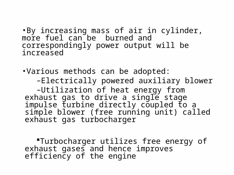
•By increasing mass of air in cylinder, more fuel can be burned and correspondingly power output will be increased
•Various methods can be adopted:–Electrically powered auxiliary blower–Utilization of heat energy from exhaust gas to
drive a single stage impulse turbine directly coupled to a simple blower (free running unit) called exhaust gas turbocharger
Turbocharger utilizes free energy of exhaust gases and hence improves efficiency of the engine
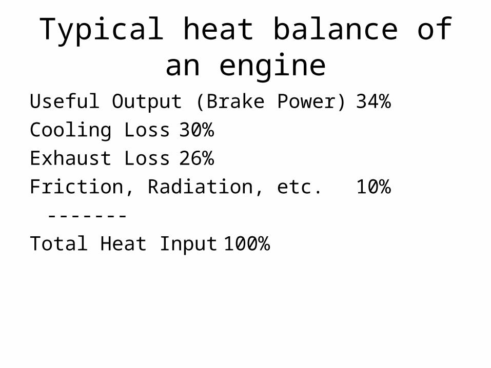
Typical heat balance of an engine
Useful Output (Brake Power) 34%
Cooling Loss 30%
Exhaust Loss 26%
Friction, Radiation, etc. 10%
-------
Total Heat Input 100%
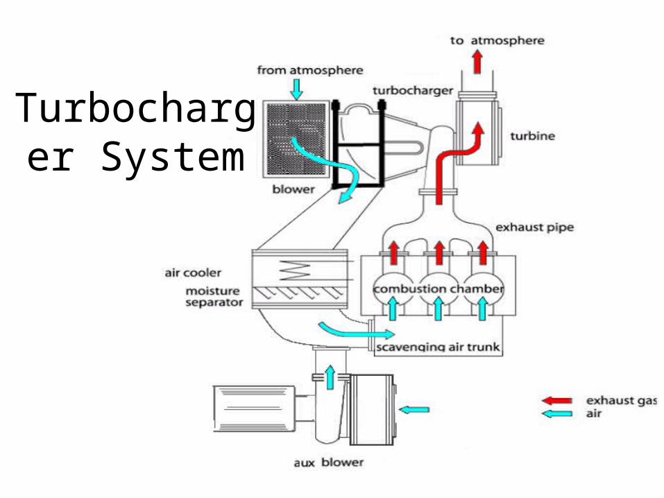
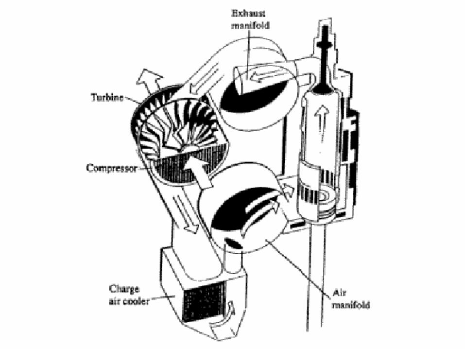
Turbocharger System
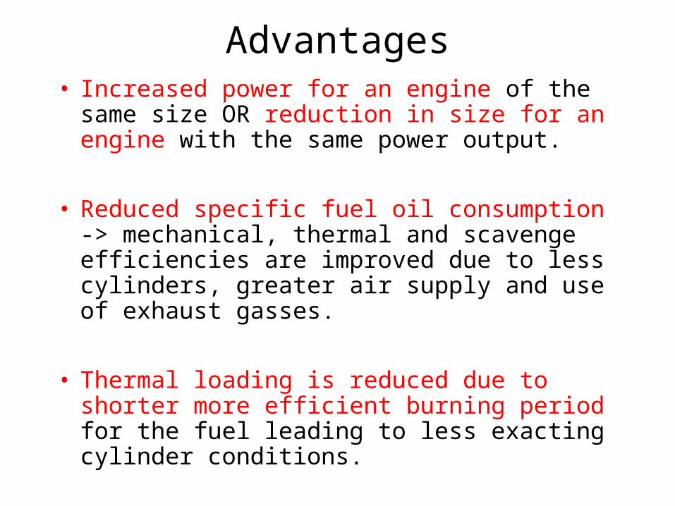
Advantages• Increased power for an engine of the same
size OR reduction in size for an engine with the same power output.
• Reduced specific fuel oil consumption -> mechanical, thermal and scavenge efficiencies are improved due to less cylinders, greater air supply and use of exhaust gasses.
• Thermal loading is reduced due to shorter more efficient burning period for the fuel leading to less exacting cylinder conditions.
Risk
• Crankcase explosion
• Scavenge fire
Design consideration
• Types of fuel and fuel oil system design • Types of lubricating oil and lubricating oil systems• Cooling systems• Waste heat utilization systems• Intake and exhaust valve systems• Starting air systems• Instrumentation system• Control and automation system• Installation items• Safety features
Summary
• Principle of ICE• Theoretical Cycles• Basic principle of operations of working cycle• Cycle & Timing Diagram• Principles of Scavenging & Arrangements• Advantages of 2S & 4S• Structural differences• Overlap of Inlet & Exhaust
References
• Introduction to Marine Engineering, • Marine Engineering , Roy L. Harrington, SNAME, 198• El-Hawary, F. (2001). Ocean Engineering Handbook. CRC
Press, UK.• Calder, Nigel (2007): Marine diesel engine: maintenance,
troubleshooting and repair.