Embed Size (px)
Citation preview
IJRET: International Journal of Research in Engineering and Technology eISSN: 2319-1163 | pISSN: 2321-7308
__________________________________________________________________________________________
Volume: 02 Issue: 11 | Nov-2013, Available @ http://www.ijret.org 703
TRANSIENT THERMAL ANALYSIS OF PHASE CHANGE MATERIAL
BASED HEAT SINKS
Azeem Anzar1, Shine K
2
1Mechanical Engineering Department, MES College of Engineering, Kuttipuram, Kerala, India
2Assistant Professor,Mechanical Engineering Department, MES College of Engineering, Kuttipuram, Kerala, India
[email protected], [email protected]
Abstract Integrated circuits operate best in a limited range of temperature hence their package must be designed to remove the excessive heat.
As an alternative passive cooling technique means, phase change materials or PCMs have been widely investigated for such transient
cooling applications considering their advantage such as high latent heat of fusion, high specific heat, controllable temperature
stability and small volume change during phase change, etc. This PCM based cooling techniques have great potential application in
the devices which are not operated continuously over a long period, but in intermittently using devices like cellular phones, digital
cameras, notebook etc. The PCM absorbs heat from the electronic component when it operates and melts, the molten PCM needs to be
re-solidified by dissipating heat to the surroundings while the electronic device are idle, such a cooling system is applicable only for
intermittent use devices and not those in continuous operation. To achieve effective cooling it is important to ensure that the operating
duration of the electronic device does not exceed the time of full melting of PCM. Advanced transient analysis is required for clear
understanding of the mechanism behind this method of cooling while practical implementations are considered. Controlled convective
cooling techniques can be implemented for continuous operation such kind of systems.
The present work is a numerical study consists of thermal analysis of various configurations of finned heat sink with PCM. The
configurations considered are finned heat sink without PCM and with PCM, Half-filled PCM towards the fin tip side and cases which
includes forced convection for systems with continuous operation.
The unsteady analyses were performed to record the transient nature of problem. The characteristic of PCM and the design of
operational time of convective cooling are estimated. By analyzing these different configurations a vivid picture of the physics of heat
transfer in PCM based heat sink is figured out.
Keywords: Phase change materials; Heatsink; electronics cooling; Thermal management
-----------------------------------------------------------------------***-----------------------------------------------------------------------
1. INTRODUCTION
Technological enhancements at the device, package and system
levels have resulted in increased functionality and decreased
form factors, but squeezed more power into ever-small packages.
As a consequence, thermal management has become more
critical for successful design of electronic devices such as
cellular phones, digital cameras, notebooksand personal digital
assistants, etc. Such devices are not operated continuously over
long periods, so a phase change material (PCM)-based cooling
system haspotential for application. Integrated circuits operate
bestwithin a limited temperature range; hence their
packagesmust be designed to remove the excessive heat. As an
alternative passive cooling technique means, PCMs have
beenwidely investigated for such transient electronic
coolingapplications considering their advantages such as
highlatent heat of fusion, high specific heat, controllable
temperature stability and small volume change during phase
change, etc.
The phase change materials (PCMs) are heat storage mediums
used in latent heat storage, as it will experience a phase
transition during the heat charge or release process.
Theoretically, PCM has a phase change point when the phase
transition happens, but in practice the phase change process
happens in a certain temperature range instead of one exact
point.
Based on the phase change process, PCMs can be classified into
solid-liquid, liquid-gas andsolid-solid PCM. Among these three
types of PCM: solid-solid PCM is rarely suitable for the thermal
storage in buildings; liquid-gas PCM experiences a very
significant volume change due to the difference of molecular
intervals between the gas and liquid; thus, in general only solid-
liquid PCM is suitable for the normal applications. Currently,
there are mainly three types of PCMs existing in the solid-liquid
category: organic-PCM,inorganic-PCM and eutectic-PCM, each
of which can be further categorized into more detailed sub-
groups
IJRET: International Journal of Research in Engineering and Technology eISSN: 2319-1163 | pISSN: 2321-7308
__________________________________________________________________________________________
Volume: 02 Issue: 11 | Nov-2013, Available @ http://www.ijret.org 704
PCM based cooling system can be implemented in conditions
where devices which are not operated continuously over a long
period, but in intermittently using devices like cellular phones,
digital cameras, notebook etc
The PCM absorbs heat from the electronic component when it
operates and melts, the molten PCM needs to be re-solidified by
dissipating heat tothe surroundings while the electronic device
are idle, such a cooling system is applicable only for intermittent
use devices and not those incontinuous operation. Forced
convection cooling with fins are common method for cooling of
chips which are in continuous operation.
2. LITERATURE REVIEW
V. Shatikian, G. Ziskind and R. Letan “Heat accumulation in a
PCM-based heat sink with internal fins” In this paper the
processes of melting of a phase-change material (PCM), in a
heat sink with a constant-heat-flux horizontal base and vertical
internal plate fins, have been studied numerically. A most
complete formulation has been attempted, which takes into
account conduction inside the fins, conduction and convection in
the PCM, volume change of the PCM associated with phase
transition, density and viscosity variation in liquid PCM, and
heat transfer to the surroundings. In a detailed parametric
investigation, the results have illustrated how the heat
accumulation due to the latent heat storage is affected by the
changes in the geometry of the system and the boundary
conditions. The results of these problems show the predominant
role of fins in transferring heat to the PCM. The approach
developed herein can be used in the design of PCM-based
cooling systems.
V. Dubovsky, E. Assis, E. Kochavi, G. Ziskind and R. Letan
“study of solidification in vertical cylindrical shells” This paper
the process of solidification of a phase change material (PCM) in
cylindrical geometry has been explored numerically. Transient
numerical simulations were performed using Fluent 6.2.
Solidification temperature of the PCM was incorporated in the
simulations along with its other properties, including the latent
and sensible specific heat, thermal conductivity and density in
solid and liquid states. The simulations provided detailed phase
distributions. To the best of our knowledge, some inherent
features of the process have been modeled for the first time,
including the curvilinear interface. An initial dimensional
analysis of the results was attempted and presented as the PCM
melt fractions vs. the Fourier and Stefan numbers. A
generalization, which encompasses the cases considered herein,
is suggested. A detailed dimensional analysis will be done in a
future study.
Gong and Arun S. Mujumadar “ A transient cooling of
electronics using phase change materials “ In this paper a well
designed PCM based heat sink for various power levels was
investigated experimentally and numerically. Results show that
the inclusion of PCM in the cavities of the heat sinks will
increases the cooling performance as compared to the cases
without involved PCM when the input power level is relatively
high. It carried out a series of numerical studies on heat transfer
during melting and freezing of single and multiple PCMs. A new
design for thermal storage using multiple PCMs was first
proposed by them for power generation in space-based activities
[1]. They extended their analysis from only the charge process
(melting) to a combined charge/discharge (melting/ freezing)
process [2].In [4], by a thermodynamic analysis, Gong and
Mujumdar found that the increase of the overall thermal
efficiency could theoretically be doubled, or even tripled by use
of multiple PCMs.
Bogdan M. Diaconu,SzabolcsVargaand Armando C. Oliveira
“Experimental assessment of heat storage properties and heat
transfercharacteristics of a phase change material slurry for air
conditioning applications”In this paper Possible applications of
the microencapsulated PCM slurryinvestigatedin this paper
include cold storage for air conditioningsystems with
intermittent energy supply such as solar-driven airconditioning
systems . Low temperature energy storage (cold storage) is an
alternative to high temperature energy storage ensuring the
cooling demand during intervals when energy supply(solar
energy in this case) is not available.
X. Duan and G.F. Naterer “Heat transfer in phase change
materials for thermal management of electric vehicle battery
modules”In this paper, thermal management with phase change
materials was investigated for their feasibility and effectiveness
for electric vehicle battery modules. Detailed solidification and
melting processes were examined and new measured PCM data
was reported. In the experiments, a heater was used to simulate a
battery cell. Two different PCM designs for the heater
temperature management were investigated: one with a PCM
container surrounding the heater, and another with a PCM jacket
wrapping the heater. It was shown that both designs are effective
in maintaining the heater temperature within a defined range.
The effects of variable heating rates and ambient temperature
conditions were also reported.
QIU Yifen, JIANG Nan, WU Wei, ZHANG Guangwei and
XIAO Baoliang “ Heat Transfer of Heat Sinking Vest with
Phase-change material” This paper develops a heat transfer
mathematical model about heat sinking vest with PCM by
enthalpy method. This model can analyze the heat transfer
process and calculate the skin heat flow covered with this vest.
On the basis of the human thermo regulation model, dynamic
temperature distribution and sweat rate of the body wearing the
vest are solved.. In addition, dynamic temperature distribution
and sweat rate comparison that body wears the vest or not show
that this vest with PCM can reduce body heat load significantly.
The heat transfer mathematical model with phase change built
above is reasonable and reliable, and it can be used to research
thermal protection performance of the heat sinking vest with
PCM.
IJRET: International Journal of Research in Engineering and Technology eISSN: 2319-1163 | pISSN: 2321-7308
__________________________________________________________________________________________
Volume: 02 Issue: 11 | Nov-2013, Available @ http://www.ijret.org 705
3. PHYSICAL MODEL
The problem defined consists of finned heat sink geometry. The
domain is simplified by imposing periodic boundary condition in
order to reduce the grid size. The work is progressed in such a
way that the performance fin computed by several situations
such as fin only, fin filled with PCM material, fin filled with
half-filled PCM and half-filled PCM based fin with forced
convection.
The geometry of heat sink for different configuration used in this
study. The fin only case, fin fully filed with pcm and fin half
filled with pcm are included.
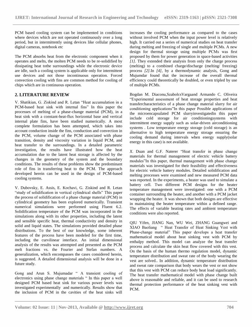
Case-1 Fin only
Case 2 Fin fully filled with PCM
Case 2 Fin half- filled with PCM
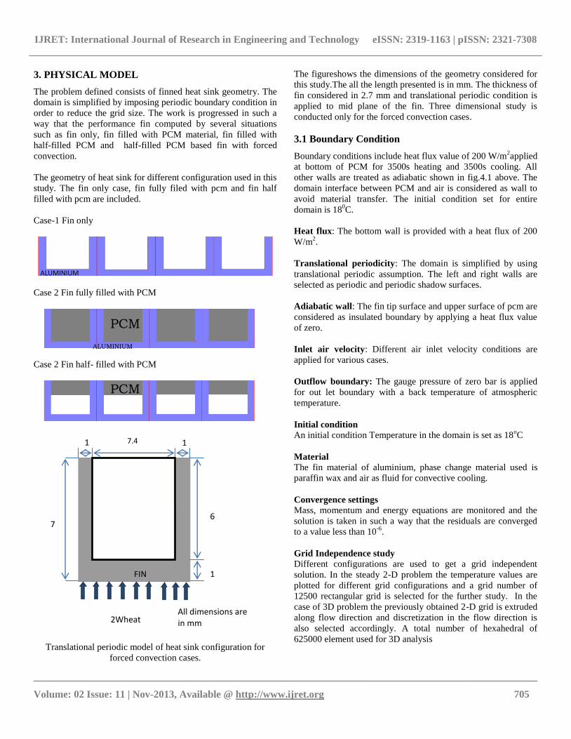
Translational periodic model of heat sink configuration for
forced convection cases.
The figureshows the dimensions of the geometry considered for
this study.The all the length presented is in mm. The thickness of
fin considered in 2.7 mm and translational periodic condition is
applied to mid plane of the fin. Three dimensional study is
conducted only for the forced convection cases.
3.1 Boundary Condition
Boundary conditions include heat flux value of 200 W/m2applied
at bottom of PCM for 3500s heating and 3500s cooling. All
other walls are treated as adiabatic shown in fig.4.1 above. The
domain interface between PCM and air is considered as wall to
avoid material transfer. The initial condition set for entire
domain is 180C.
Heat flux: The bottom wall is provided with a heat flux of 200
W/m2.
Translational periodicity: The domain is simplified by using
translational periodic assumption. The left and right walls are
selected as periodic and periodic shadow surfaces.
Adiabatic wall: The fin tip surface and upper surface of pcm are
considered as insulated boundary by applying a heat flux value
of zero.
Inlet air velocity: Different air inlet velocity conditions are
applied for various cases.
Outflow boundary: The gauge pressure of zero bar is applied
for out let boundary with a back temperature of atmospheric
temperature.
Initial condition
An initial condition Temperature in the domain is set as 18oC
Material
The fin material of aluminium, phase change material used is
paraffin wax and air as fluid for convective cooling.
Convergence settings
Mass, momentum and energy equations are monitored and the
solution is taken in such a way that the residuals are converged
to a value less than 10-6
.
Grid Independence study
Different configurations are used to get a grid independent
solution. In the steady 2-D problem the temperature values are
plotted for different grid configurations and a grid number of
12500 rectangular grid is selected for the further study. In the
case of 3D problem the previously obtained 2-D grid is extruded
along flow direction and discretization in the flow direction is
also selected accordingly. A total number of hexahedral of
625000 element used for 3D analysis
2Wheat
FIN
7.4 1.3
1
.3
6
1.3
7.3
All dimensions are in mm
ALUMINIUM
PCM
PCM
ALUMINIUM
IJRET: International Journal of Research in Engineering and Technology eISSN: 2319-1163 | pISSN: 2321-7308
__________________________________________________________________________________________
Volume: 02 Issue: 11 | Nov-2013, Available @ http://www.ijret.org 706
4. MATHEMATICAL AND NUMERICAL
MODELING
4.1 Numerical Simulation
FLUENT can be used to solve fluid flow problems involving
solidification and/or melting taking place at one temperature
(e.g., in pure metals) or over a range of temperatures (e.g., in
binary alloys). Instead of tracking the liquid-solid front
explicitly, FLUENT uses an enthalpy-porosity formulation. The
liquid-solid mushy zone is treated as a porous zone with porosity
equal to the liquid fraction, and appropriate momentum sink
terms are added to the momentum equations to account for the
pressure drop caused by the presence of solid material. Sinks are
also added to the turbulence equations to account for reduced
porosity in the solid regions. FLUENT uses control volume
approach to solve fluid flow problems. In finite volume method,
flow domain is discretized into cells and analysis is done by
solving the governing equations on control points on cells. The
finite volume method represents and evaluates partial differential
equations as algebraic equations.
The instantaneous continuity equation, momentum equation and
energy equation for a compressible fluid can be written as:
Continuity Equation:
𝜕𝜌
𝜕𝑡+
𝜕
𝜕𝑥𝑗 𝜌𝑢𝑗 = 0…………………………..……3(a)
Momentum equation
𝜕
𝜕𝑡 𝜌𝑢𝑖 +
𝜕
𝜕𝑥𝑗 𝜌𝑢𝑖𝑢𝑗 + 𝑝𝛿𝑖𝑗 − 𝜏𝑗𝑖 = 0……….…3(b)
Energy equation
𝜕
𝜕𝑡 𝜌𝑒0 +
𝜕
𝜕𝑥𝑗 𝜌𝑢𝑗𝑒0 + 𝑢𝑗𝑝 + 𝑞𝑗 − 𝑢𝑖𝜏𝑖𝑗 = 0…..3(c)
For a Newtonian fluid, assuming Stokes Law for mono-atomic
gases, the viscous stress is given by
𝜏𝑖𝑗 = 2𝜇𝑆𝑖𝑗 …………………………………..3(d)
Where the trace-less viscous strain-rate is defined by
𝑆𝑖𝑗 =1
2 𝜕𝑢𝑖
𝜕𝑥𝑗+
𝜕𝑢𝑗
𝜕𝑥𝑖 −
1
3
𝜕𝑢𝑘
𝜕𝑥𝑘𝛿𝑖𝑗 ………..…….3(e)
The heat-flux, qj, is given by Fourier's law:
𝑞𝑗 = −𝜆𝜕𝑇
𝜕𝑥𝑗= −𝐶𝑝
𝜇
𝑃𝑟
𝜕𝑇
𝜕𝑥𝑗…………………….3(f)
Where the laminar Prandtl number Pris defined by:
𝑃𝑟 =𝐶𝑝𝜇
𝜆……………..…………………..…..3(g)
To close these equations it is also necessary to specify an
equation of state. Assuming a calorically perfect gas the
following relations are valid:
𝛾 =𝐶𝑝
𝐶𝑣, P = ρRT, e = CvT, Cv- Cp= R
Where γ, Cv ,Cp and R are constant.
The total energy e0 is defined by:
𝑒0 = 𝑒 +𝑈𝑘𝑈𝑘
2…………………………………3(h)
4.2 Favre Averaged Equations
It is not possible to solve the instantaneous equations directly for
most engineering applications. At the Reynolds numbers
typically present in real cases these equations have very chaotic
turbulent solutions, and it is necessary to model the influence of
the smallest scales. Most turbulence models are based on one-
point averaging of the instantaneous equations. The averaging
procedure will be described in the following sections.
Let ϕ be any dependent variable. It is convenient to define two
different types of averaging of ϕ:
Classical time averaging (Reynolds averaging)
ϕ =1
T ϕ t dt………………………….3(i)
ϕ’ = ϕ − ϕ
Density weighted time averaging (Favre averaging):
Φ =ρΦ
ρ ……………………….……..3(j)
Φ" = Φ − Φ
Note that with the above definitions, ϕ′ = 0 but 𝛟" ≠ 𝟎
And 𝜙′ = 0but Ø ≠ 0
4.3 Solidification Modeling
FLUENT can be used to solve fluid flow problems involving
solidification and/or melting taking place at one temperature
(e.g., in pure metals) or over a range of temperatures (e.g., in
binary alloys). Instead of tracking the liquid-solid front
explicitly, FLUENT uses an enthalpy-porosity formulation. The
liquid-solid mushy zone is treated as a porous zone with porosity
equal to the liquid fraction, and appropriate momentum sink
terms are added to the momentum equations to account for the
pressure drop caused by the presence of solid material. Sinks are
also added to the turbulence equations to account for reduced
porosity in the solid regions.
IJRET: International Journal of Research in Engineering and Technology eISSN: 2319-1163 | pISSN: 2321-7308
__________________________________________________________________________________________
Volume: 02 Issue: 11 | Nov-2013, Available @ http://www.ijret.org 707
The enthalpy of the material is computed as the sum of the
sensible enthalpy, h, and the latent heat, ∆H:
𝐻 = ℎ + ∆𝐻…….....................................................3(k)
Where h = href + 𝐶𝑝𝑇
𝑇𝑟𝑒𝑓dT
…………………..…………3(l)
And href= reference enthalpy
Tref=reference temperature
Cp=specific heat at constant pressure
The liquid fraction, β, can be defined as
𝛽 = 0𝑖𝑓𝑇 < 𝑇𝑠𝑜𝑙𝑖𝑑𝑢𝑠
𝛽 = 1𝑖𝑓𝑇 < 𝑇𝑙𝑖𝑞𝑢𝑖𝑑𝑢𝑠𝑠
𝛽 =𝑇−𝑇𝑆𝑜𝑙𝑖𝑑𝑢𝑠
𝑇𝑙𝑖𝑞𝑢𝑖𝑑𝑢𝑠 −𝑇𝑆𝑜𝑙𝑖𝑑𝑢𝑠𝑖𝑓𝑇𝑠𝑜𝑙𝑖𝑑𝑢𝑠 < 𝑇 < 𝑇𝑙𝑖𝑞𝑢𝑖𝑑𝑢𝑠
……3(m)
The latent heat content can now be written in terms of the latent
heat of the material, L:
∆𝐻 = 𝛽𝐿
Energy Equations
For solidification or melting problems, the energy equation is
written as
𝜕
𝜕𝑡 𝜌𝐻 + 𝛻. 𝜌𝑣 𝐻 = 𝛻. 𝑘𝛻𝑇 + 𝑆………………………………3(n)
Where
𝐻 = 𝑒𝑛𝑡ℎ𝑎𝑙𝑝𝑦
𝜌 = 𝑑𝑒𝑛𝑠𝑖𝑡𝑦
𝐻 = 𝑒𝑛𝑡ℎ𝑎𝑙𝑝𝑦
𝑉 = Fluid velocity
S= source term
The solution for temperature is essentially iteration between the
energy equations and the liquid fraction equation
The enthalpy-porosity technique treats the mushy region
(partially solidified region) as a porous medium. The porosity in
each cell is set equal to the liquid fraction in that cell. In fully
solidified regions, the porosity is equal to zero, which
extinguishes the velocities in these regions. The momentum sink
due to the reduced porosity in the mushy zone takes the
following form:
𝑆 = 1−𝛽 2
𝛽3+휀 𝐴𝑚𝑢𝑠 ℎ 𝑣 ………………………………………3(o)
S= Momentum source term, 𝑣 = Fluid velocity
Default value of 100000 and 0.001 is used the constants Amush
and ɛ simultaneously
4.4 Analysis Procedure
The modeling of flow domain has been completed using
geometry and mesh building software, GAMBIT. General
sequence of operation involved is:
1) Create full geometry and decompose into mesh able
sections.
2) Give meshes required.
3) Continuum and boundary attachment.
4) Export Mesh.
Analysis is done using FLUENT software. General sequence of
operation involved is:
1) Importing grid.
2) Checking grid.
3) Setting units.
4) Define solver properties (steady, unsteady, 2D/3D etc).
5) Define Model (Solidification and heating , turbulent
properties)
6) Define material properties (density, viscosity variation
etc..).
7) Define operating conditions.
8) Define boundary conditions.
9) Initialization.
10) Setting convergence criteria.
11) Iterating until the solution converges.
4.5 Fluent Settings
Geometry is created using GAMBIT. Two dimensional model is
created. Discretization is done by using mapped quad mesh with
boundary layer on solid fluid interface. Gambit file is exported
as .mesh format. The settings of ANSYS Fluent 14 for numerical
solution are listed in this section. The discretized geometry is
imported into Fluent. Fluent will perform various checks on the
mesh and will report the progress in the console. It is needed to
make sure that the minimum volume is a positive number. The
imported grid is checked and proper scaling is done. The
required units are selected.
General settings: The general settings such as solver settings,
details of temporal discretization, properties of materials and
equations required solving and additional physics required etc.
are selected depend on the problem.Table listed shows the basic
solver settings provided.
Model Settings
Space 2D/3D
Solver Pressure based
Time Steady / Unsteady, 1st-Order
Implicit
IJRET: International Journal of Research in Engineering and Technology eISSN: 2319-1163 | pISSN: 2321-7308
__________________________________________________________________________________________
Volume: 02 Issue: 11 | Nov-2013, Available @ http://www.ijret.org 708
Viscous Laminar
Heat Transfer Enabled
Solidification and
Melting Enabled
Modeling Solidification: Solidification & Melting is enabled in
order to satisfy phase change conditions. The default value of
100000 selected for the mushy zone.
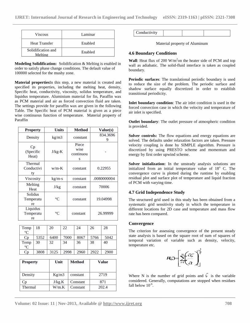
Material propertiesIn this step, a new material is created and
specified its properties, including the melting heat, density,
Specific heat, conductivity, viscosity, solidus temperature, and
liquidus temperature. Aluminium material for fin, Paraffin wax
as PCM material and air as forced convection fluid are taken.
The settings provide for paraffin wax are given in the following
Table. The Specific heat of PCM material is given as a piece
wise continuous function of temperature. Material property of
Paraffin
Property Units Method Value(s)
Density kg/m3 constant 834.3696
9
Cp
(Specific
Heat)
J/kg-K
Piece
wise
continuou
s
-
Thermal
Conductivi
ty
w/m-K constant 0.22955
Viscosity kg/m-s constant .0080000004
Melting
Heat J/kg constant 70006
Solidus
Temperatu
re
°C constant 19.04998
Liquidus
Temperatu
re
°C constant 26.99999
Temp
ºC
18 20 22 24 26 28
Cp 5352 6400 7000 8067 5766 5042
Temp
ºC
30 32 34 36 38 40
Cp 3808 3125 2998 2960 2922 2900
Property Unit Method Value
Density Kg/m3 constant 2719
Cp J/kg.K Constant 871
Thermal W/m.K Constant 202.4
Conductivity
Material property of Aluminum
4.6 Boundary Conditions
Wall: Heat flux of 200 W/m2on the heater side of PCM and top
wall as adiabatic. The solid-fluid interface is taken as coupled
boundary.
Periodic surfaces: The translational periodic boundary is used
to reduce the size of the problem. The periodic surface and
shadow surface equally discretized in order to establish
transitional periodicity.
Inlet boundary condition: The air inlet condition is used in the
forced convection case in which the velocity and temperature of
air inlet is specified.
Outlet boundary: The outlet pressure of atmospheric condition
is provided.
Solver controls: The flow equations and energy equations are
solved. The defaults under relaxation factors are taken. Pressure
velocity coupling is done by SIMPLE algorithm. Pressure is
discretized by using PRESTO scheme and momentum and
energy by first order upwind scheme.
Solver initialization: In the unsteady analysis solutions are
initialized from an initial temperature value of 18o C. The
convergence curve is plotted during the runtime by enabling
residual plot and surface plot of temperature and liquid fraction
of PCM with varying time.
4.7 Grid Independence Study
The structured grid used in this study has been obtained from a
systematic grid sensitivity study in which the temperature in
different locations for 2D case and temperature and mass flow
rate has been compared.
Convergence
The criterion for assessing convergence of the present steady
state analysis is based on the square root of sum of squares of
temporal variation of variable such as density, velocity,
temperature etc. 1
2 2
1
( )N
ii
R
t
Where N is the number of grid points and is the variable
considered. Generally, computations are stopped when residues
fall below 10-6
.
IJRET: International Journal of Research in Engineering and Technology eISSN: 2319-1163 | pISSN: 2321-7308
__________________________________________________________________________________________
Volume: 02 Issue: 11 | Nov-2013, Available @ http://www.ijret.org 709
In addition to this the mass imbalance is also checked in the
same manner.
510in out
in
m m
m
Where min is the mass fluid entering the domain and mout is the
mass fluid leaving the domain.
5. RESULTS AND DISCUSSION
5.1 Introduction
The result from the different analysis is reported in this chapter.
The various cases such as fin only, fin fully filled with PCM,
half-filled fin with forced convection etc. are reported one by
one. The characteristics of PCM on heating and cooling are
analysed and discussed. The cases with different velocity
boundary conditions are compared and a strategy of intermittent
use of convective heat transfer is established. The geometry,
grid, boundary conditions and numerical settings adopted etc. are
discussed in previous chapters. The results are presented in the
form of contours of temperature, liquid fraction and heat transfer
coefficient.
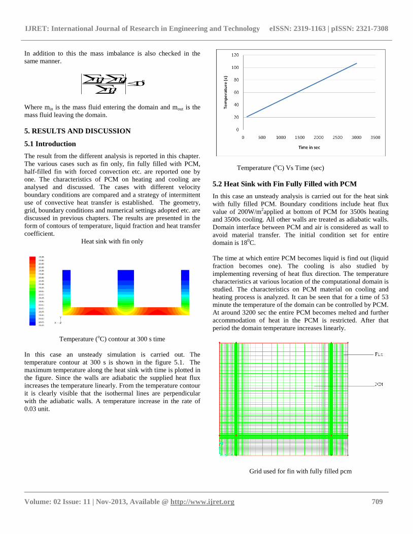
Heat sink with fin only
Temperature (oC) contour at 300 s time
In this case an unsteady simulation is carried out. The
temperature contour at 300 s is shown in the figure 5.1. The
maximum temperature along the heat sink with time is plotted in
the figure. Since the walls are adiabatic the supplied heat flux
increases the temperature linearly. From the temperature contour
it is clearly visible that the isothermal lines are perpendicular
with the adiabatic walls. A temperature increase in the rate of
0.03 unit.
Temperature (oC) Vs Time (sec)
5.2 Heat Sink with Fin Fully Filled with PCM
In this case an unsteady analysis is carried out for the heat sink
with fully filled PCM. Boundary conditions include heat flux
value of 200W/m2applied at bottom of PCM for 3500s heating
and 3500s cooling. All other walls are treated as adiabatic walls.
Domain interface between PCM and air is considered as wall to
avoid material transfer. The initial condition set for entire
domain is 180C.
The time at which entire PCM becomes liquid is find out (liquid
fraction becomes one). The cooling is also studied by
implementing reversing of heat flux direction. The temperature
characteristics at various location of the computational domain is
studied. The characteristics on PCM material on cooling and
heating process is analyzed. It can be seen that for a time of 53
minute the temperature of the domain can be controlled by PCM.
At around 3200 sec the entire PCM becomes melted and further
accommodation of heat in the PCM is restricted. After that
period the domain temperature increases linearly.
Grid used for fin with fully filled pcm
IJRET: International Journal of Research in Engineering and Technology eISSN: 2319-1163 | pISSN: 2321-7308
__________________________________________________________________________________________
Volume: 02 Issue: 11 | Nov-2013, Available @ http://www.ijret.org 710
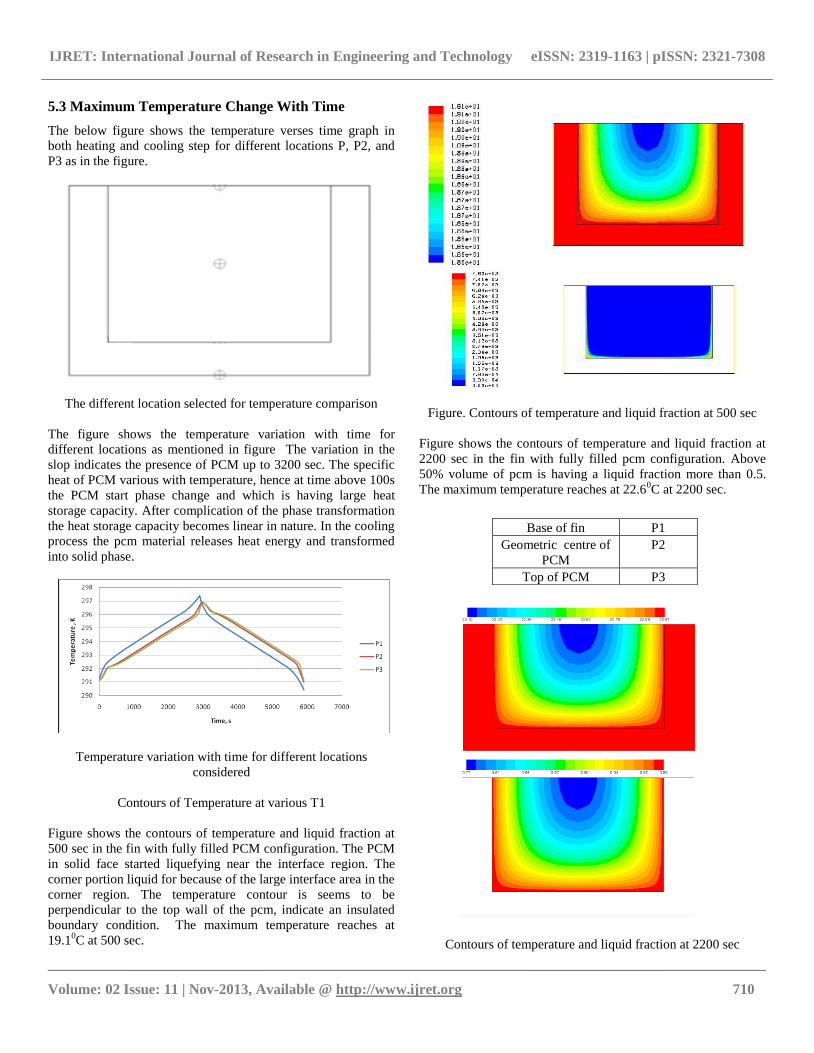
5.3 Maximum Temperature Change With Time
The below figure shows the temperature verses time graph in
both heating and cooling step for different locations P, P2, and
P3 as in the figure.
The different location selected for temperature comparison
The figure shows the temperature variation with time for
different locations as mentioned in figure The variation in the
slop indicates the presence of PCM up to 3200 sec. The specific
heat of PCM various with temperature, hence at time above 100s
the PCM start phase change and which is having large heat
storage capacity. After complication of the phase transformation
the heat storage capacity becomes linear in nature. In the cooling
process the pcm material releases heat energy and transformed
into solid phase.
Temperature variation with time for different locations
considered
Contours of Temperature at various T1
Figure shows the contours of temperature and liquid fraction at
500 sec in the fin with fully filled PCM configuration. The PCM
in solid face started liquefying near the interface region. The
corner portion liquid for because of the large interface area in the
corner region. The temperature contour is seems to be
perpendicular to the top wall of the pcm, indicate an insulated
boundary condition. The maximum temperature reaches at
19.10C at 500 sec.
Figure. Contours of temperature and liquid fraction at 500 sec
Figure shows the contours of temperature and liquid fraction at
2200 sec in the fin with fully filled pcm configuration. Above
50% volume of pcm is having a liquid fraction more than 0.5.
The maximum temperature reaches at 22.60C at 2200 sec.
Contours of temperature and liquid fraction at 2200 sec
Base of fin P1
Geometric centre of
PCM
P2
Top of PCM P3
IJRET: International Journal of Research in Engineering and Technology eISSN: 2319-1163 | pISSN: 2321-7308
__________________________________________________________________________________________
Volume: 02 Issue: 11 | Nov-2013, Available @ http://www.ijret.org 711
Figure shows the contours of temperature and liquid fraction at
3500 sec in the fin with fully filled pcm configuration. It can be
seen that the minimum temperature in the pcm domain is 25.20C
(above themelting limit) and hence the entire portion of pcm is
converted in to liquid and at/after that the variation in the
temperature of system changed linearly.
Contours of temperature and liquid fraction at 3500 sec
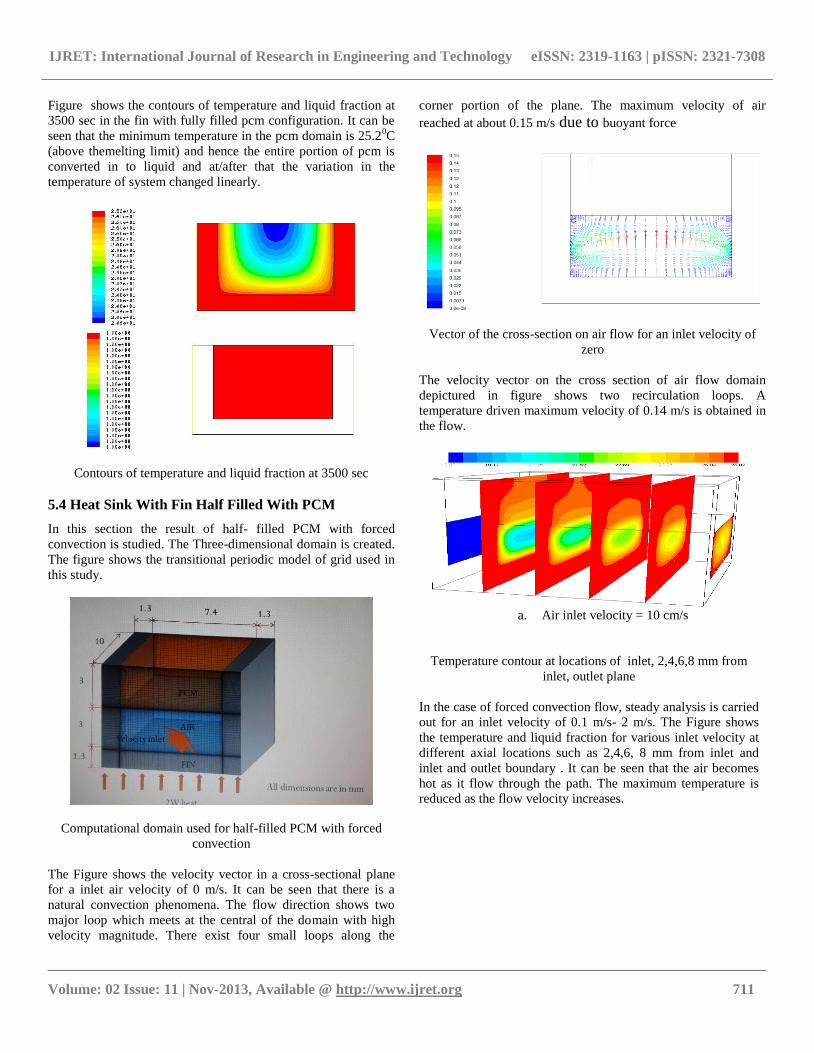
5.4 Heat Sink With Fin Half Filled With PCM
In this section the result of half- filled PCM with forced
convection is studied. The Three-dimensional domain is created.
The figure shows the transitional periodic model of grid used in
this study.
Computational domain used for half-filled PCM with forced
convection
The Figure shows the velocity vector in a cross-sectional plane
for a inlet air velocity of 0 m/s. It can be seen that there is a
natural convection phenomena. The flow direction shows two
major loop which meets at the central of the domain with high
velocity magnitude. There exist four small loops along the
corner portion of the plane. The maximum velocity of air
reached at about 0.15 m/s due to buoyant force
Vector of the cross-section on air flow for an inlet velocity of
zero
The velocity vector on the cross section of air flow domain
depictured in figure shows two recirculation loops. A
temperature driven maximum velocity of 0.14 m/s is obtained in
the flow.
a. Air inlet velocity = 10 cm/s
Air inlet velocity = 50 cm/s
Temperature contour at locations of inlet, 2,4,6,8 mm from
inlet, outlet plane
In the case of forced convection flow, steady analysis is carried
out for an inlet velocity of 0.1 m/s- 2 m/s. The Figure shows
the temperature and liquid fraction for various inlet velocity at
different axial locations such as 2,4,6, 8 mm from inlet and
inlet and outlet boundary . It can be seen that the air becomes
hot as it flow through the path. The maximum temperature is
reduced as the flow velocity increases.
IJRET: International Journal of Research in Engineering and Technology eISSN: 2319-1163 | pISSN: 2321-7308
__________________________________________________________________________________________
Volume: 02 Issue: 11 | Nov-2013, Available @ http://www.ijret.org 712
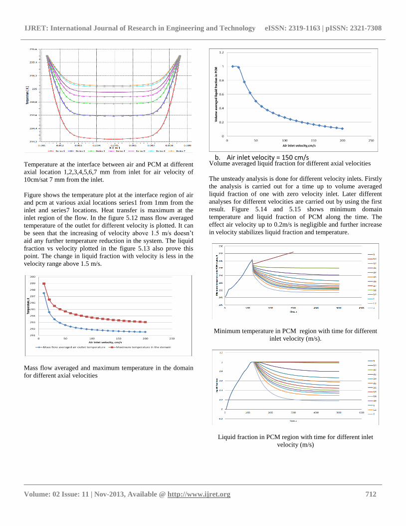
Temperature at the interface between air and PCM at different
axial location 1,2,3,4,5,6,7 mm from inlet for air velocity of
10cm/sat 7 mm from the inlet.
Figure shows the temperature plot at the interface region of air
and pcm at various axial locations series1 from 1mm from the
inlet and series7 locations. Heat transfer is maximum at the
inlet region of the flow. In the figure 5.12 mass flow averaged
temperature of the outlet for different velocity is plotted. It can
be seen that the increasing of velocity above 1.5 m/s doesn’t
aid any further temperature reduction in the system. The liquid
fraction vs velocity plotted in the figure 5.13 also prove this
point. The change in liquid fraction with velocity is less in the
velocity range above 1.5 m/s.
Mass flow averaged and maximum temperature in the domain
for different axial velocities
b. Air inlet velocity = 150 cm/s
Volume averaged liquid fraction for different axial velocities
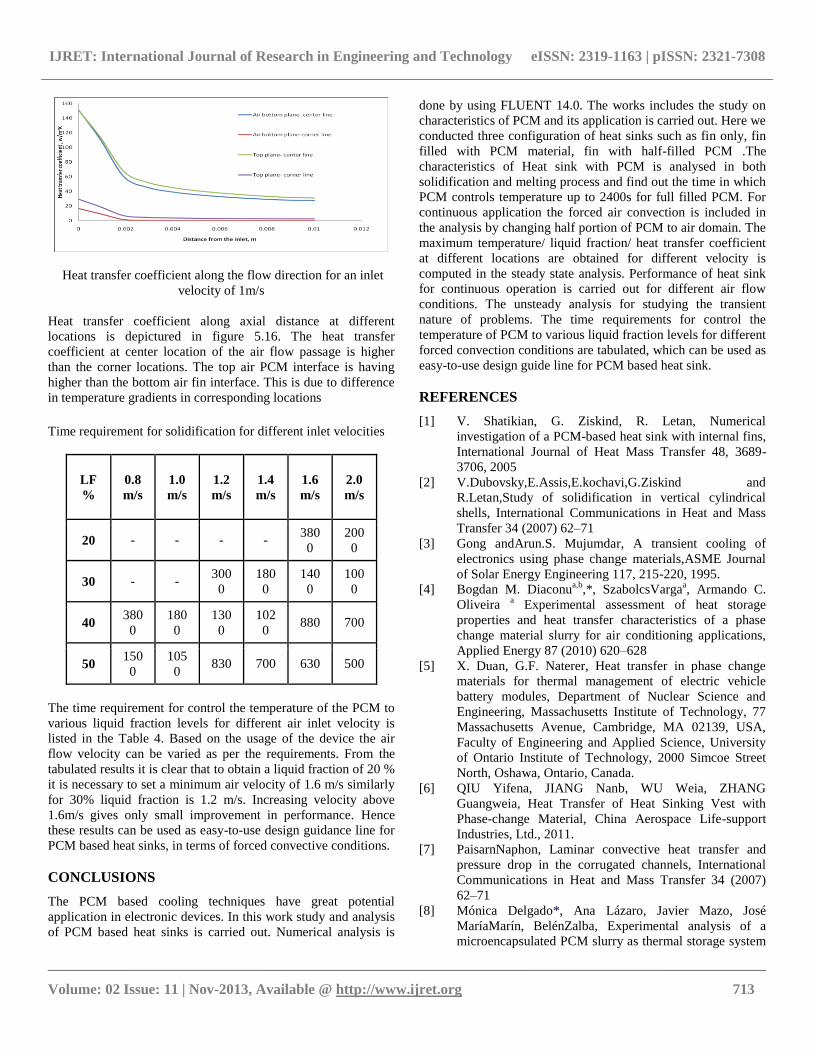
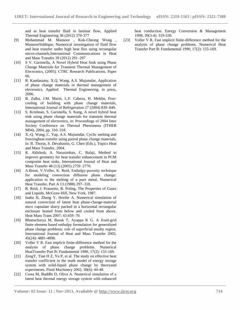
The unsteady analysis is done for different velocity inlets. Firstly
the analysis is carried out for a time up to volume averaged
liquid fraction of one with zero velocity inlet. Later different
analyses for different velocities are carried out by using the first
result. Figure 5.14 and 5.15 shows minimum domain
temperature and liquid fraction of PCM along the time. The
effect air velocity up to 0.2m/s is negligible and further increase
in velocity stabilizes liquid fraction and temperature.
Minimum temperature in PCM region with time for different
inlet velocity (m/s).
Liquid fraction in PCM region with time for different inlet
velocity (m/s)
IJRET: International Journal of Research in Engineering and Technology eISSN: 2319-1163 | pISSN: 2321-7308
__________________________________________________________________________________________
Volume: 02 Issue: 11 | Nov-2013, Available @ http://www.ijret.org 713
Heat transfer coefficient along the flow direction for an inlet
velocity of 1m/s
Heat transfer coefficient along axial distance at different
locations is depictured in figure 5.16. The heat transfer
coefficient at center location of the air flow passage is higher
than the corner locations. The top air PCM interface is having
higher than the bottom air fin interface. This is due to difference
in temperature gradients in corresponding locations
Time requirement for solidification for different inlet velocities
LF
%
0.8
m/s
1.0
m/s
1.2
m/s
1.4
m/s
1.6
m/s
2.0
m/s
20 - - - - 380
0
200
0
30 - - 300
0
180
0
140
0
100
0
40 380
0
180
0
130
0
102
0 880 700
50 150
0
105
0 830 700 630 500
The time requirement for control the temperature of the PCM to
various liquid fraction levels for different air inlet velocity is
listed in the Table 4. Based on the usage of the device the air
flow velocity can be varied as per the requirements. From the
tabulated results it is clear that to obtain a liquid fraction of 20 %
it is necessary to set a minimum air velocity of 1.6 m/s similarly
for 30% liquid fraction is 1.2 m/s. Increasing velocity above
1.6m/s gives only small improvement in performance. Hence
these results can be used as easy-to-use design guidance line for
PCM based heat sinks, in terms of forced convective conditions.
CONCLUSIONS
The PCM based cooling techniques have great potential
application in electronic devices. In this work study and analysis
of PCM based heat sinks is carried out. Numerical analysis is
done by using FLUENT 14.0. The works includes the study on
characteristics of PCM and its application is carried out. Here we
conducted three configuration of heat sinks such as fin only, fin
filled with PCM material, fin with half-filled PCM .The
characteristics of Heat sink with PCM is analysed in both
solidification and melting process and find out the time in which
PCM controls temperature up to 2400s for full filled PCM. For
continuous application the forced air convection is included in
the analysis by changing half portion of PCM to air domain. The
maximum temperature/ liquid fraction/ heat transfer coefficient
at different locations are obtained for different velocity is
computed in the steady state analysis. Performance of heat sink
for continuous operation is carried out for different air flow
conditions. The unsteady analysis for studying the transient
nature of problems. The time requirements for control the
temperature of PCM to various liquid fraction levels for different
forced convection conditions are tabulated, which can be used as
easy-to-use design guide line for PCM based heat sink.
REFERENCES
[1] V. Shatikian, G. Ziskind, R. Letan, Numerical
investigation of a PCM-based heat sink with internal fins,
International Journal of Heat Mass Transfer 48, 3689-
3706, 2005
[2] V.Dubovsky,E.Assis,E.kochavi,G.Ziskind and
R.Letan,Study of solidification in vertical cylindrical
shells, International Communications in Heat and Mass
Transfer 34 (2007) 62–71
[3] Gong andArun.S. Mujumdar, A transient cooling of
electronics using phase change materials,ASME Journal
of Solar Energy Engineering 117, 215-220, 1995.
[4] Bogdan M. Diaconua,b
,*, SzabolcsVargaa, Armando C.
Oliveira a Experimental assessment of heat storage
properties and heat transfer characteristics of a phase
change material slurry for air conditioning applications,
Applied Energy 87 (2010) 620–628
[5] X. Duan, G.F. Naterer, Heat transfer in phase change
materials for thermal management of electric vehicle
battery modules, Department of Nuclear Science and
Engineering, Massachusetts Institute of Technology, 77
Massachusetts Avenue, Cambridge, MA 02139, USA,
Faculty of Engineering and Applied Science, University
of Ontario Institute of Technology, 2000 Simcoe Street
North, Oshawa, Ontario, Canada.
[6] QIU Yifena, JIANG Nanb, WU Weia, ZHANG
Guangweia, Heat Transfer of Heat Sinking Vest with
Phase-change Material, China Aerospace Life-support
Industries, Ltd., 2011.
[7] PaisarnNaphon, Laminar convective heat transfer and
pressure drop in the corrugated channels, International
Communications in Heat and Mass Transfer 34 (2007)
62–71
[8] Mónica Delgado*, Ana Lázaro, Javier Mazo, José
MaríaMarín, BelénZalba, Experimental analysis of a
microencapsulated PCM slurry as thermal storage system
IJRET: International Journal of Research in Engineering and Technology eISSN: 2319-1163 | pISSN: 2321-7308
__________________________________________________________________________________________
Volume: 02 Issue: 11 | Nov-2013, Available @ http://www.ijret.org 714
and as heat transfer fluid in laminar flow, Applied
Thermal Engineering 36 (2012) 370-377
[9] Mohammad M. Mansoor , Kok-Cheong Wong ,
MansoorSiddique, Numerical investigation of fluid flow
and heat transfer under high heat flux using rectangular
micro-channels,International Communications in Heat
and Mass Transfer 39 (2012) 291–297
[10] S V. Garimella, A Novel Hybrid Heat Sink using Phase
Change Materials for Transient Thermal Management of
Electronics, (2005). CTRC Research Publications. Paper
66.
[11] R. Kandasamy, X.Q. Wang, A.S. Mujumdar, Application
of phase change materials in thermal management of
electronics, Applied Thermal Engineering, in press,
2006.
[12] B. Zalba, J.M. Marin, L.F. Cabeza, H. Mehlin, Free-
cooling of building with phase change materials,
International Journal of Refrigeration 27 (2004) 839–849.
[13] S. Krishnan, S. Garimella, S. Kang, A novel hybrid heat
sink using phase change materials for transient thermal
management of electronics, in: Proceedings of 2004 Inter
Society Conference on Thermal Phenomena (ITHER
M04), 2004, pp. 310–318.
[14] X.-Q. Wang, C. Yap, A.S. Mujumdar, Cyclic melting and
freezingheat transfer using paired phase change materials,
in: B. Thorat, S. Devahastin, G. Chen (Eds.), Topics Heat
and Mass Transfer, 2004.
[15] R. Akhilesh, A. Narasimhan, C. Balaji, Method to
improve geometry for heat transfer enhancement in PCM
composite heat sinks, International Journal of Heat and
Mass Transfer 48 (13) (2005) 2759–2770.
[16] A.Brent, V.Voller, K. Reid, Enthalpy-porosity technique
for modeling convection diffusion phase change:
application to the melting of a pure metal, Numerical
Heat Transfer, Part A 13 (1988) 297–318.
[17] R. Reid, J. Prausnitz, B. Poling, The Properties of Gases
and Liquids, McGraw-Hill, New York, 1987.
[18] Inaba H, Zhang Y, Horibe A. Numerical simulation of
natural convection of latent heat phase-change-material
mico capsulate slurry packed in a horizontal rectangular
enclosure heated from below and cooled from above.
Heat Mass Trans 2007; 43:459–70.
[19] Bhattacharya M, Basak T, Ayappa K G. A fixed-grid
finite element based enthalpy formulation for generalized
phase change problems: role of superficial mushy region.
International Journal of Heat and Mass Transfer 2002,
45(24): 4881-4898.
[20] Voller V R. Fast implicit finite-difference method for the
analysis of phase change problems. Numerical
HeatTransfer Part B: Fundamental 1990, 17(2): 155-169.
[21] ZengY, Tian H Z, Yu P, et al. The study on effective heat
transfer coefficient in the math model of energy storage
system with solid-liquid phase change by theoryand
experiments. Fluid Machinery 2002, 30(6): 44-48.
[22] Costa M, Buddhi D, Oliva A. Numerical simulation of a
latent heat thermal energy storage system with enhanced
heat conduction. Energy Conversion & Management
1998, 39(3-4): 319-330.
[23] Voller V R. Fast implicit finite-difference method for the
analysis of phase change problems. Numerical Heat
Transfer Part B: Fundamental 1990, 17(2): 155-169.