Embed Size (px)
Citation preview
TPM Tracking Device for Machine Shop 2014-15
Dr.J.J.M.C.O.E Page 1
CHAPTER 1
Introduction
TPM Tracking Device for Machine Shop 2014-15
Dr.J.J.M.C.O.E Page 2
CHAPTER 1
1.1 Introduction:
In today’s scenario huge losses/wastage occurs in manufacturing shop floor.
this wastage occurs because of operators, maintenance person, process and tooling
problems and non-availability of components in time etc. other forms of wastage
includes idle machine, idle manpower ,break down machine, rejected parts etc.. This
quality related wastage are having significant importance as they are deals with time,
profit and reputation of company. There are also several factors, which can be
monitored by TPM like speed of machine, start up losses of machine, break down of
machine and bottle neck in process. Zero oriented concept such as zero tolerance for
waste, defects, break down and zero accidents are becoming a pre-requisite in
manufacturing and assembly industry. In this situation, a revolutionary concept of
TPM has been adopted in many industries across the world to address above
problems.[1,4]
TPM is a maintenance management program with the objective of eliminating
equipment downtime. It focuses on overall equipment effectiveness, covering areas
such as breakdowns, setups, and an ability to maintain cutting tolerances, capacity and
more.TPM which stands for “Total Productive Maintenance”.
Maintenance is one of the areas in modern management to increase machine
productivity and to produce quality products. This obviously improves equipment
efficiency rates and reduces costs. So, our project consists of a well-conceived TPM
implementation program not only improves the equipment efficiency and
effectiveness but also brings appreciable improvements in other areas of the
manufacturing enterprise. The circuit that we are going to design will control the
operation of VMC machines used in industries. The records will vary by company,
but at a minimum, they should include:
Date of problem
Description of problem
Time the machine was inoperable
TPM Tracking Device for Machine Shop 2014-15
Dr.J.J.M.C.O.E Page 3
Problem resolution steps
Final solution
Permanent corrective action plans
CNC/VMC machines are used for atomizing purpose in industries to get
accurate and fast product within less time. Our circuit will control the machines start
cycle, stop cycle and if breakdown occurs at any time, it will ask for a reason.
In order to fulfill all the requirements of controlling or minimizing wastage
from material and manufacturing product in time a device like TPM is necessary[4,8]
1.2 TPM History-
TPM is an innovative concept. The origin of TPM can be tracked back to
1951 when preventive maintenance was introduced in Japan. Nippondenso was 1’
St Company to introduce plant wide preventive maintenance in 1960. With the
automation of Nippondenso, maintenance became a problem as more
maintenance personnel required. So, management decide that the routine
maintenance of equipment would be carried out by operator. Thus, Nippondenso
which already followed preventive maintenance also added autonomous
maintenance done by production operator. The maintenance crew went in
equipment modification for improving reliability. The modification were made or
incorporated in new equipment. This led to maintenance preventive. Thus,
preventive maintenance along with maintenance prevention and maintainability
improvement gave birth to productive maintenance. The aim of maintenance was
to maximize plant and equipment effectiveness to achieve optimum life cycle cost
of production equipment. By then Nipppondenso had made quality circle
involving the employee’s participation. Thus all employees took part in
implementing productive maintenance. [6,7]

TPM Tracking Device for Machine Shop 2014-15
Dr.J.J.M.C.O.E Page 4
1.3 About TPM concept –
What is Total Productive Maintenance (TPM)?
Total Productive Maintenance (TPM) is a maintenance program,
which involves a newly defined concept for maintaining plants and equipment. The
goal of the TPM program is to markedly increase production while, at the same time,
increasing employee morale and job satisfaction.
TPM brings maintenance into focus as a necessary and vitally
important part of the business. It is no longer re-garded as a non-profit activity. Down
time for maintenance is scheduled as a part of the manufacturing day and, in some
cases, as an integral part of the manufacturing process. The goal is to hold emergency
and unscheduled maintenance to a minimum. [5,8]
Why TPM?
TPM was introduced to achieve the following objectives. The important ones are
listed below.
a. Avoid wastage in a quickly changing economic environment.
b. Producing goods without reducing product quality.
c. Reduce cost.
d. Produce a low batch quantity at the earliest possible time.
e. Goods send to the customers must be non-defective. [2]
1.4 Benefits of TPM –
a. Increase productivity and OEE (Overall equipment efficiency).
b. Rectify customer complaints.
c. Reduce accidents.
d. Follow pollution control measure.
e. Keep workplace clean.
f. Reduce manufacturing cost to great extent.

TPM Tracking Device for Machine Shop 2014-15
Dr.J.J.M.C.O.E Page 5
TPM Tracking Device for Machine Shop 2014-15
Dr.J.J.M.C.O.E Page 6
CHAPTER 2
Literature Review &
Present theory and practices
TPM Tracking Device for Machine Shop 2014-15
Dr.J.J.M.C.O.E Page 7
CHAPTER 2
Literature Review &Present theory and practices:
2.1 Literature review-
1] Mr.Melesse Workneh Wakjira, Mr.Ajit Pal Singh evaluated the contributions of
total productive maintenance (TPM) in the paper “TOTAL PRODUCTIVE
MAINTENANCE: A CASE STUDY IN MANUFACTURING INDUSTRY” Global
Journal of researches in engineering Industrial engineering (February 2012) [1, 2]
The purpose of this paper is to evaluate the contributions of total productive
maintenance (TPM) initiatives towards improving manufacturing performance in
Ethiopian malt manufacturing industry. The correlations between various TPM
implementation dimensions and manufacturing performance improvements have been
evaluated and validated by employing overall equipment effectiveness (OEE) in
boiler plant. The research focuses upon the significant contributions of TPM
implementation success factors like top management leadership and involvement,
traditional maintenance practices and holistic
TPM implementation initiatives, towards affecting improvements in manufacturing
performance in the Ethiopian industry. The study establishes that focused TPM
implementation over a reasonable time period can strategically contribute towards
realization of significant manufacturing performance enhancements. The study
highlights the strong potential of TPM implementation initiatives in affecting
organizational performance improvements. The achievements of Ethiopian
manufacturing organizations through proactive TPM initiatives have been evaluated
and critical TPM success factors identified for enhancing the effectiveness of TPM
implementation programs in the Ethiopian context. [1, 2]
2] Mr. Sharma Kumar Rajiv& Mrs. Sharma Pooja explained the system reliability
analysts/managers/engineers/ practitioners to conduct RAM analysis of the system in
the paper “COMPUTING RAM INDICES FOR RELIABLE OPERATION OF
PRODUCTION SYSTEMS” on 7th April 2012 [3]
TPM Tracking Device for Machine Shop 2014-15
Dr.J.J.M.C.O.E Page 8
The purpose of this paper is to permit the system reliability engineers/
practitioners to conduct RAM analysis of the system which may helps them to model,
analyze and predict the behavior of industrial systems in a more realistic and
consistent manner. Design/methodology/approach: Markova approach is used to
model the system behavior. For carrying out study, Root Cause Analysis (RCA) of the
subsystems is carried out and transition diagrams for various subsystems are drawn
and differential equations associated with them are formulated. After obtaining the
steady state solution the corresponding values of reliability and maintainability are
estimated at different mission times.
Research limitations/implications: Based on the RAM analysis, possible
maintenance strategies can be investigated which might help the plant personnel to
improve the system effectiveness. Practical Implications: Without exercising much
effort in developing complex system models, the proposed method for analyzing
system performance may prove helpful to the reliability analysts/
engineers/practitioners to model analyze and predict the behavior of system more
efficiently and resolve the RAM requirements of the system in unison.
Originality/value: The simultaneous adoption of both qualitative (RCA) and
quantitative (Markov approach) approach to analyze and obtain RAM indices for
measuring the system performance helps the maintenance engineers to improve RAM
aspects after understanding the failure behavior of component(s) in the system.[3]
3] P.Prakash, S.Kumar, T.Sakthieswaran they are explained or analysis the Total
Productive maintenance (TPM) is an innovative approach which holds the potential
for enhancing efficiency of production facilities. in the paper “IMPLEMENTATION
OF TOTAL PRODUCTIVE MAINTENANCE IN INDUSTRY – A CASE STUDY”
International Journal of Engineering Trends and Technology (IJETT) -
Volume4Issue4- April 2013 [4]
Total Productive maintenance (TPM) is an innovative approach which holds
the potential for enhancing Efficiency of production facilities. TPM is a process that
maximizes the productivity of equipment for its entire life. It demands significant
change of work culture and radical restructuring of work. It eliminates breakdowns
and promotes autonomous operator maintenance through day-to-day activities, which
TPM Tracking Device for Machine Shop 2014-15
Dr.J.J.M.C.O.E Page 9
involve the total workforce. It fosters an environment where improvement efforts in
safety, quality, cost, delivery and creativity are encouraged through the participation
of all employees. It is a strategic management initiative to increase capacity and end
the vicious cycle of breakdown or reactive repairs through the use of autonomous and
predictive maintenance, as well as equipment modifications to facilitate optimum
machine availability, quality and performance. TPM will drive the operational
efficiency of a manufacturing environment and profitability of the organization. In our
project we focus on studying the existing methods for rescheduling Section Layout,
implementing 5S Principles in the shop floor, manufacturing systems management,
and maintenance management and to improve the efficiency of process with TPM
implementation. 5s is an integral step in TPM. It focuses on developing stability and
standardization in the organization. It can provide benefits in areas from safety to
quality. [4]
2.2 Present theory and practices
The Total Productive Maintenance (TPM) system serves as a bridge between
production department of industry& computer by connecting the network with GUI
form. The supervisor can access the information of any VMC/CNC machine from
anywhere at any time simply by Sitting in front of PC to which the Ethernet cable is
connected. The TPM system uses machine strings which come continuously from
machine when job is done in each shift. The input may be given when all the essential
information is feed into machine panel and start it. The circuit with AVR controller
will take data from machine and store string and forward to computer through serial
communication. On computer there is provision made to show required data into their
standard format using GUI system. For that VB.net software tool is used. To arrange
the data taken into tabular form sql software also used.
TPM Tracking Device for Machine Shop 2014-15
Dr.J.J.M.C.O.E Page 10
We have decided to choose “TPM Tracking Device” as our project because:
a. Industry demand for such a system which will help them to show
machine information into their standard format.
b. The system used is Intelligent for Interaction between machine and
Production department.
c. And we will provide the industry with all sorts of related information
for their concern.
d. This project will help owner to keep track of data so that he can
monitor performance of machine and operator.
e. Owner can see performance of machines or operators, through single
PC only. So this removes hard work of monitoring.
f. Due to this type of monitoring, operators gave their best to increase
machine performance and productivity and ultimately it increases
profit.
g. Data kept is in digital format, hence paper work is reduces.
h. As data is in digital format. One can easily regain that data whenever
necessary.
TPM Tracking Device for Machine Shop 2014-15
Dr.J.J.M.C.O.E Page 11
CHAPTER 3
Relevance of Work
TPM Tracking Device for Machine Shop 2014-15
Dr.J.J.M.C.O.E Page 12
CHAPTER 3
Relevance of Work:
The AVR controller is the heart of system. It consists of segments, each designed
for a specific purpose. They are;
1. AVR based decision device.
2. Ethernet protocol to send data.
3. GUI system built in P.C. to visualize the data as per company requirement.
3.1 AVR based decision device-
The circuit having AVR controller in it will take data from VMC machine. It will
compare and sense the taken data with standard data which is already given to AVR
controller through programming. The output of AVR processor is stored in EEPROM
memory.
3.2 Ethernet protocol –
To send machine data to maintenance department the proper channel is required
which is capable to visualize data received in company required manner. Ethernet is
the most popular LAN technology in the world. It is an easy, relatively inexpensive
way to provide high-performance networking to all different types of computer
equipment.
3.3 GUI system built in P.C.-
Graphical user interface that allows users to interact with electronic devices through
graphical icons and visual indicators such as secondary notation, as opposed to text-
based interfaces, typed command labels or text navigation. GUIs were introduced in
reaction to the perceived steep learning curve of command-line interfaces which
require commands to be typed on the keyboard.
TPM Tracking Device for Machine Shop 2014-15
Dr.J.J.M.C.O.E Page 13
CHAPTER 4
Hardware Implementation
TPM Tracking Device for Machine Shop 2014-15
Dr.J.J.M.C.O.E Page 14
CHAPTER 4
Hardware Implementation:
4.1 Block Diagram-
The above fig 4.1 shows the block representation of TPM tracking system for
machine shop. System will take data from VMC machine. Parameters of VMC
machine will act as an input to our system. The strings which come from machine will
be stored into internal EEPROM of controller, the external EEPROM memory can be
interface with controller in order to expand memory capacity and keep record of data.
The system also consists of prototype simulator. The simulator is nothing but one of
hardware which sends strings like VMC machine into controller for demo purpose. In
most of industries they favor to send their data through wired medias so, in our system
we are using the Ethernet cable to send data from AVR controller to maintenance
department computer. Ethernet is the collective name for a variety of closely related
network standards. As a network standard, each version of Ethernet includes
specifications for the physical network layer how the signals will be sent and
received. Protocols like IP or NetWare, in contrast, define communications without
reference to the physical transport medium. It treats the various Ethernet standards as
if they were protocols, discriminating among them based on the unique form each one
gives to packet headers.
The data receive by manufacturing department should follow their standard
format. In order to convert the information coming from machine into standard
manner we are going to design one software which takes data and merge it into their
standard format. The GUI system is connected with P.C. A graphical user interface
(GUI) is a human-computer interface that uses and menu and which can be
manipulated by a mouse. GUIs stand in sharp contrast to command line interfaces,
which use only text and are accessed solely by a keyboard. A window is a rectangular
portion of the monitor screen that can display its contents program independently of
the rest of the display screen. A major feature is the ability for multiple windows to be
open simultaneously. Each window can display a different application, or each can
display different files that have been opened or created with a single application.

TPM Tracking Device for Machine Shop 2014-15
Dr.J.J.M.C.O.E Page 15
The three phase sensing and temperature control unit will give the current
information about three phase supply and cooling fan system on LCD.
Fig. 4.1 Block diagram for project
TPM Tracking Device for Machine Shop 2014-15
Dr.J.J.M.C.O.E Page 16
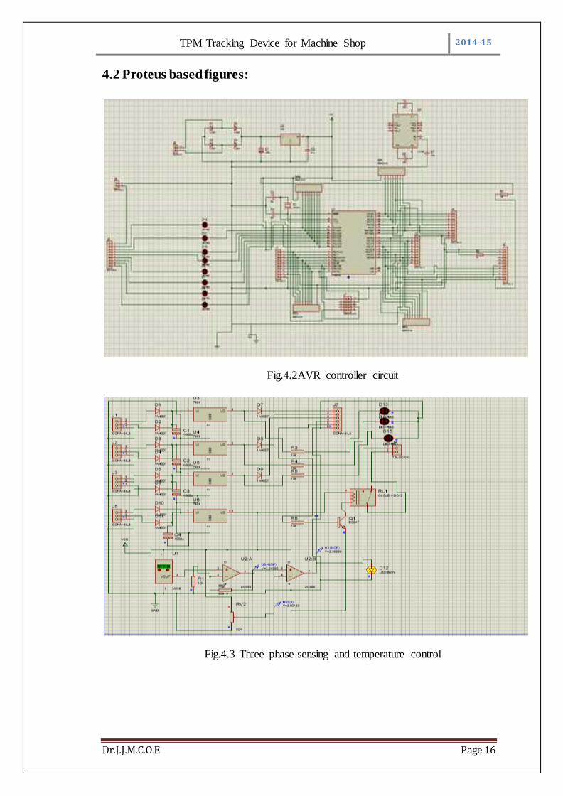
4.2 Proteus based figures:
Fig.4.2AVR controller circuit
Fig.4.3 Three phase sensing and temperature control
TPM Tracking Device for Machine Shop 2014-15
Dr.J.J.M.C.O.E Page 17
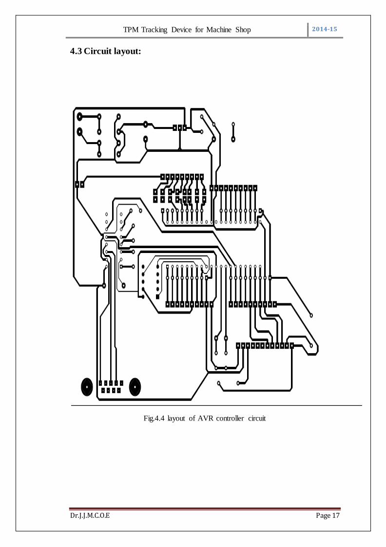
4.3 Circuit layout:
Fig.4.4 layout of AVR controller circuit
TPM Tracking Device for Machine Shop 2014-15
Dr.J.J.M.C.O.E Page 18
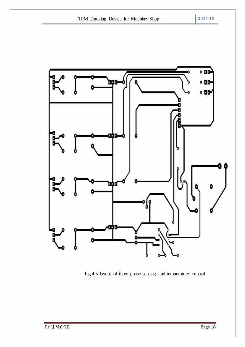
Fig.4.5 layout of three phase sensing and temperature control

TPM Tracking Device for Machine Shop 2014-15
Dr.J.J.M.C.O.E Page 19
4.4 List of Components:
Sr. No. Components used Quantity
1. ATMEGA16 AVR controller 1
2. MAX RS232 1
3. LM 35 1
4. IL 358 OP-AMP 4
5. Transformer (6-0-6,500mA ) 3
6. Transformer (12-0-12,1mA )
Crystal (12 MHz)
1
7. Resistors
100 Ω
100k(pre-set)
80 k
10k
470Ω
1
1
1
1
4
8. Capacitors
100 µF
100 uF
10 uF
1 uF
1 nF
0.01 uF
4700 uF,
4
3
1
1
2
10
1
9. Diodes
1N
1N4007
12
4
10. Push to on Switch 9
11. Connectors and cables
6 pin
1
2

TPM Tracking Device for Machine Shop 2014-15
Dr.J.J.M.C.O.E Page 20
4 pin
2 pin
6
12. IC base
40 pin
8 pin
16 pin
One each
13. Discrete Components
DC motor(fan)
LEDs
12 V Rely
One each
14. PCBs 2
Table 4.1: List of Components
The transformer (12-0-12,2A) coverts the 230V AC input to the 12-0-12 V
AC. The diodes 1N4007 placed in a Centre tapped configuration convert the AC into
pulsating DC. The filter capacitor 100 uF, 35V electrolytic filters the pulsating DC
and makes it pure DC. The regulator IC’s ensuring the output DC voltage to be in the
specified range.
The ATMEGA16 AVR controller works on a 5V DC supplied by the
regulator. The 3 phase sensing circuit and temperature control unit also work on 5 and
12 volts respectively so, filtering IC’s are used to provide proper filtered supply.
The relay is works on a 12V DC supply. The work of relay is to determine on
the basis of set temperature and varied temperature sensed by LM 35. The two
temperatures are compared by comparator circuit which is to be designed with help of
OP-amp IC IL 358. Comparator output is high then switching operation of relay takes
place and cooling fan gets ON.
TPM Tracking Device for Machine Shop 2014-15
Dr.J.J.M.C.O.E Page 21
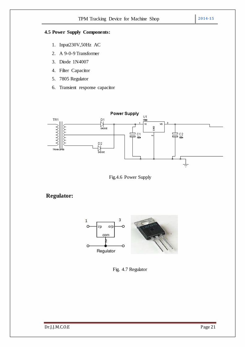
4.5 Power Supply Components:
1. Input230V,50Hz AC
2. A 9-0-9 Transformer
3. Diode 1N4007
4. Filter Capacitor
5. 7805 Regulator
6. Transient response capacitor
Fig.4.6 Power Supply
Regulator:
Fig. 4.7 Regulator

TPM Tracking Device for Machine Shop 2014-15
Dr.J.J.M.C.O.E Page 22
Pin Description:
Pin
No
Function Name
1 Input voltage (5V-18V) Input
2 Ground (0V) Ground
3 Regulated output; 5V (4.8V-5.2V) Output
Table No.:4.2 Pin Descriptions of 7805
Regulator eliminates ripple by setting DC output to a fixed voltage. Voltage
regulator ICs are available with fixed (typically 5V, 12V and 15V) or variable output
voltages. Negative voltage regulators are also available.
Many of the fixed voltage regulator ICs has 3 leads (input, output and high
impedance). They include a hole for attaching a heat sink if necessary.
Features of LM7805:
Output Current up to 1A
Output Voltages of 5, 6, 8, 9, 10, 12, 15, 18, 24V
Thermal Overload Protection
Short Circuit Protection
Output Transistor Safe Operating Area Protection
TPM Tracking Device for Machine Shop 2014-15
Dr.J.J.M.C.O.E Page 23
4.6 AVR IC ATMEGA16:
AVR ATMEGA16 the AVR is a high performance controller providing
advanced in system programming and test capabilities for general purpose logic
integration. It is comprised for four ports, providingwith propagation delays of 14.2us
and work at maximum speed of 16MHz frequency[9]
4.6.1 Features:
High Performance, Low Power Atmel®AVR® 8-bit Microcontroller
a. Advanced RISC Architecture
i. 131 Powerful Instructions - Most Single Clock Cycle Execution
ii. 32 × 8 General Purpose Working Registers
iii. Fully Static Operation
iv. Up to 1 MIPS throughput per MHz
v. On-chip 2-cycle Multiplier
b. Data and Non-Volatile Program Memory
i. 16/32/64K Bytes Flash of In-System Programmable Program
Memory
ii. 512B/1K/2K Bytes of In-System Programmable EEPROM
iii. 1/2/4K Bytes Internal SRAM
iv. Write/Erase Cycles: 10,000 Flash/ 100,000 EEPROM
v. Data Retention: 20 years at 85°C/ 100 years at 25°C
vi. Optional Boot Code Section with Independent Lock Bits
c. In-System Programming by On-chip Boot Program
d. True Read-While-Write Operation
i. Programming Lock for Flash Program and EEPROM Data
Security
e. On Chip Debug Interface (debug WIRE)
f. CAN 2.0A/B with 6 Message Objects - ISO 16845 Certified
g. LIN 2.1 and 1.3 Controller or 8-Bit UART
h. One 12-bit High Speed PSC (Power Stage Controller)
i. Non Overlapping Inverted PWM Output Pins with Flexible Dead-
Time
ii. Variable PWM duty Cycle and Frequency
TPM Tracking Device for Machine Shop 2014-15
Dr.J.J.M.C.O.E Page 24
iii. Synchronous Update of all PWM Registers
i. Peripheral Features
i. One 8-bit General purpose Timer/Counter with Separate Presales,
Compare Mode And Capture Mode
ii. One 16-bit General purpose Timer/Counter with Separate presales,
Compare Mode and Capture Mode
iii. One Master/Slave SPI Serial Interface
iv. 10-bit ADC Up To 11 Single Ended Channels and 3 Fully
Differential ADC Channel Pairs Programmable Gain (5×, 10×, 20×,
40×) on Differential Channels Internal Reference Voltage Direct
Power Supply Voltage Measurement
v. 10-bit DAC for Variable Voltage Reference (Comparators, ADC)
vi. Four Analog Comparators with Variable Threshold Detection
vii. 100μA ±2% Current Source (LIN Node Identification)
viii. Interrupt and Wake-up on Pin Change
ix. Programmable Watchdog Timer with Separate On-Chip Oscillator
j. Special Microcontroller Features
i. Low Power Idle, Noise Reduction, and Power Down Modes
ii. Power On Reset and Programmable Brown Out Detection
iii. In-System Programmable via SPI Port
iv. High Precision Crystal Oscillator for CAN Operations (16MHz)
v. Internal Calibrated RC Oscillator ( 8MHz)
vi. On-chip PLL for fast PWM ( 32MHz, 64MHz) and CPU (16MHz)
k. Operating Voltage: 2.7V - 5.5V
l. Extended Operating Temperature:
i. -40°C to +85°C
m. Core Speed Grade:
i. 0 - 8MHz @ 2.7 - 4.5V
ii. 0 - 16MHz @ 4.5 - 5.5V
TPM Tracking Device for Machine Shop 2014-15
Dr.J.J.M.C.O.E Page 25
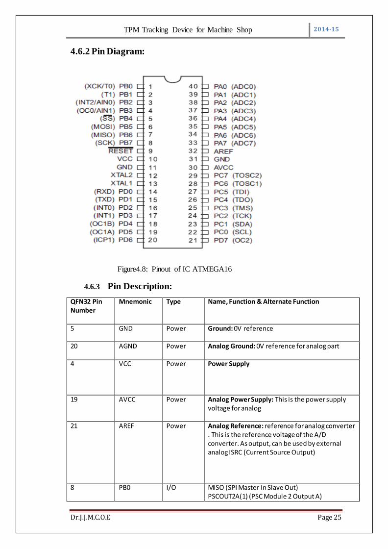
4.6.2 Pin Diagram:
Figure4.8: Pinout of IC ATMEGA16
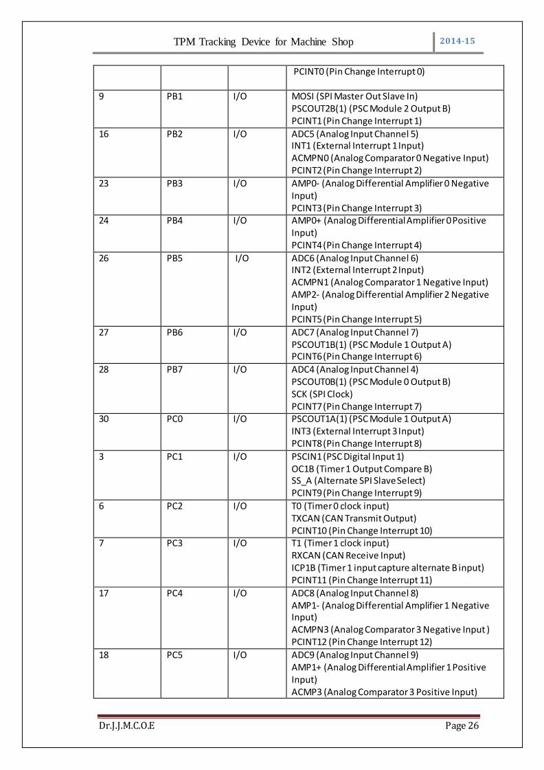
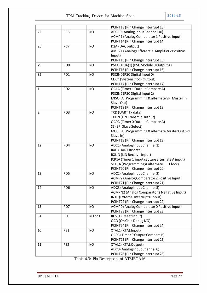
4.6.3 Pin Description:
QFN32 Pin Number
Mnemonic
Type
Name, Function & Alternate Function
5 GND Power Ground: 0V reference
20 AGND Power Analog Ground: 0V reference for analog part
4
VCC Power Power Supply
19
AVCC Power
Analog Power Supply: This is the power supply voltage for analog
21
AREF Power Analog Reference: reference for analog converter . This is the reference voltage of the A/D converter. As output, can be used by external analog ISRC (Current Source Output)
8
PB0 I/O MISO (SPI Master In Slave Out) PSCOUT2A(1) (PSC Module 2 Output A)
TPM Tracking Device for Machine Shop 2014-15
Dr.J.J.M.C.O.E Page 26
PCINT0 (Pin Change Interrupt 0)
9
PB1 I/O
MOSI (SPI Master Out Slave In) PSCOUT2B(1) (PSC Module 2 Output B) PCINT1 (Pin Change Interrupt 1)
16
PB2 I/O
ADC5 (Analog Input Channel 5) INT1 (External Interrupt 1 Input) ACMPN0 (Analog Comparator 0 Negative Input) PCINT2 (Pin Change Interrupt 2)
23
PB3 I/O AMP0- (Analog Differential Amplifier 0 Negative Input) PCINT3 (Pin Change Interrupt 3)
24
PB4 I/O AMP0+ (Analog Differential Amplifier 0 Positive Input) PCINT4 (Pin Change Interrupt 4)
26
PB5 I/O ADC6 (Analog Input Channel 6) INT2 (External Interrupt 2 Input) ACMPN1 (Analog Comparator 1 Negative Input) AMP2- (Analog Differential Amplifier 2 Negative Input) PCINT5 (Pin Change Interrupt 5)
27
PB6 I/O ADC7 (Analog Input Channel 7) PSCOUT1B(1) (PSC Module 1 Output A) PCINT6 (Pin Change Interrupt 6)
28
PB7 I/O ADC4 (Analog Input Channel 4) PSCOUT0B(1) (PSC Module 0 Output B) SCK (SPI Clock) PCINT7 (Pin Change Interrupt 7)
30
PC0 I/O PSCOUT1A(1) (PSC Module 1 Output A) INT3 (External Interrupt 3 Input) PCINT8 (Pin Change Interrupt 8)
3 PC1 I/O
PSCIN1 (PSC Digital Input 1) OC1B (Timer 1 Output Compare B) SS_A (Alternate SPI Slave Select) PCINT9 (Pin Change Interrupt 9)
6
PC2 I/O
T0 (Timer 0 clock input) TXCAN (CAN Transmit Output) PCINT10 (Pin Change Interrupt 10)
7
PC3 I/O
T1 (Timer 1 clock input) RXCAN (CAN Receive Input) ICP1B (Timer 1 input capture alternate B input) PCINT11 (Pin Change Interrupt 11)
17
PC4 I/O
ADC8 (Analog Input Channel 8) AMP1- (Analog Differential Amplifier 1 Negative Input) ACMPN3 (Analog Comparator 3 Negative Input ) PCINT12 (Pin Change Interrupt 12)
18 PC5 I/O
ADC9 (Analog Input Channel 9) AMP1+ (Analog Differential Amplifier 1 Positive Input) ACMP3 (Analog Comparator 3 Positive Input)
TPM Tracking Device for Machine Shop 2014-15
Dr.J.J.M.C.O.E Page 27
PCINT13 (Pin Change Interrupt 13) 22
PC6 I/O ADC10 (Analog Input Channel 10) ACMP1 (Analog Comparator 1 Positive Input) PCINT14 (Pin Change Interrupt 14)
25
PC7 I/O
D2A (DAC output) AMP2+ (Analog Differential Amplifier 2 Positive Input) PCINT15 (Pin Change Interrupt 15)
29
PD0 I/O PSCOUT0A(1) (PSC Module 0 Output A) PCINT16 (Pin Change Interrupt 16)
32
PD1 I/O PSCIN0 (PSC Digital Input 0) CLKO (System Clock Output) PCINT17 (Pin Change Interrupt 17)
1
PD2 I/O OC1A (Timer 1 Output Compare A) PSCIN2 (PSC Digital Input 2) MISO_A (Programming & alternate SPI Master In Slave Out) PCINT18 (Pin Change Interrupt 18)
2
PD3 I/O TXD (UART Tx data) TXLIN (LIN Transmit Output) OC0A (Timer 0 Output Compare A) SS (SPI Slave Select) MOSI_A (Programming & alternate Master Out SPI Slave In) PCINT19 (Pin Change Interrupt 19)
12
PD4 I/O ADC1 (Analog Input Channel 1) RXD (UART Rx data) RXLIN (LIN Receive Input) ICP1A (Timer 1 input capture alternate A input) SCK_A (Programming & alternate SPI Clock) PCINT20 (Pin Change Interrupt 20)
13
PD5 I/O ADC2 (Analog Input Channel 2) ACMP2 (Analog Comparator 2 Positive Input) PCINT21 (Pin Change Interrupt 21)
14
PD6 I/O ADC3 (Analog Input Channel 3) ACMPN2 (Analog Comparator 2 Negative Input) INT0 (External Interrupt 0 Input) PCINT22 (Pin Change Interrupt 22)
15
PD7 I/O ACMP0 (Analog Comparator 0 Positive Input) PCINT23 (Pin Change Interrupt 23)
31
PE0 I/O or I RESET (Reset Input) OCD (On Chip Debug I/O) PCINT24 (Pin Change Interrupt 24)
10 PE1 I/O
XTAL1 (XTAL Input) OC0B (Timer 0 Output Compare B) PCINT25 (Pin Change Interrupt 25)
11 PE2 I/O XTAL2 (XTAL Output) ADC0 (Analog Input Channel 0) PCINT26 (Pin Change Interrupt 26)
Table 4.3: Pin Description of ATMEGA16
TPM Tracking Device for Machine Shop 2014-15
Dr.J.J.M.C.O.E Page 28
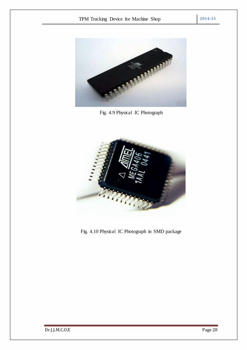
Fig. 4.9 Physical IC Photograph
Fig. 4.10 Physical IC Photograph in SMD package
TPM Tracking Device for Machine Shop 2014-15
Dr.J.J.M.C.O.E Page 29
4.6.4 Connections of IC ATMEGA16:
PORT B:
Out of 8 pins of PORT B PB0 to PB5 pins are used for connection.
PB0 pin is connected to the RS enable of LCD.
PB1 pin is connected to the Enable of LCD.
PB2 to PB5 pins are connected to the D4 to D7 of LCD Respectively.
PORT A:
PA0 pin is used to detect R phase of supply.
PA1 pin is used to detect Y phase of supply.
PA2 pin is used to detect B phase of supply.
PA3 pin is used to detect whether cooling fan is ON or OFF.
PORT D:
PD0 pin is used to receive string from CNC/VMC machine.
PD1 pin is used transmit the string to serial port.
TPM Tracking Device for Machine Shop 2014-15
Dr.J.J.M.C.O.E Page 30
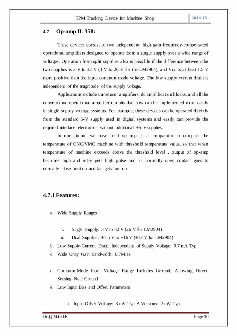
4.7 Op-amp IL 358:
These devices consist of two independent, high-gain frequency-compensated
operational amplifiers designed to operate from a single supply over a wide range of
voltages. Operation from split supplies also is possible if the difference between the
two supplies is 3 V to 32 V (3 V to 26 V for the LM2904), and VCC is at least 1.5 V
more positive than the input common-mode voltage. The low supply-current drain is
independent of the magnitude of the supply voltage.
Applications include transducer amplifiers, dc amplification blocks, and all the
conventional operational amplifier circuits that now can be implemented more easily
in single-supply-voltage systems. For example, these devices can be operated directly
from the standard 5-V supply used in digital systems and easily can provide the
required interface electronics without additional ±5-V supplies.
In our circuit ,we have used op-amp as a comparator to compare the
temperature of CNC/VMC machine with threshold temperature value, so that when
temperature of machine exceeds above the threshold level , output of op-amp
becomes high and relay gets high pulse and its normally open contact goes to
normally close position and fan gets turn on.
4.7.1 Features:
a. Wide Supply Ranges
i. Single Supply: 3 V to 32 V (26 V for LM2904)
ii. Dual Supplies: ±1.5 V to ±16 V (±13 V for LM2904)
b. Low Supply-Current Drain, Independent of Supply Voltage: 0.7 mA Typ
c. Wide Unity Gain Bandwidth: 0.7MHz
d. Common-Mode Input Voltage Range Includes Ground, Allowing Direct
Sensing Near Ground
e. Low Input Bias and Offset Parameters
i. Input Offset Voltage: 3 mV Typ A Versions: 2 mV Typ
TPM Tracking Device for Machine Shop 2014-15
Dr.J.J.M.C.O.E Page 31
ii. Input Offset Current: 2 nA Typ
iii. Input Bias Current: 20 nA Typ A Versions: 15 nA Type
f. Differential Input Voltage Range Equal to Maximum-Rated Supply Voltage:
32 V (26 V for LM2904)
g. Open-Loop Differential Voltage Gain: 100dB Typ
h. Internal Frequency Compensation
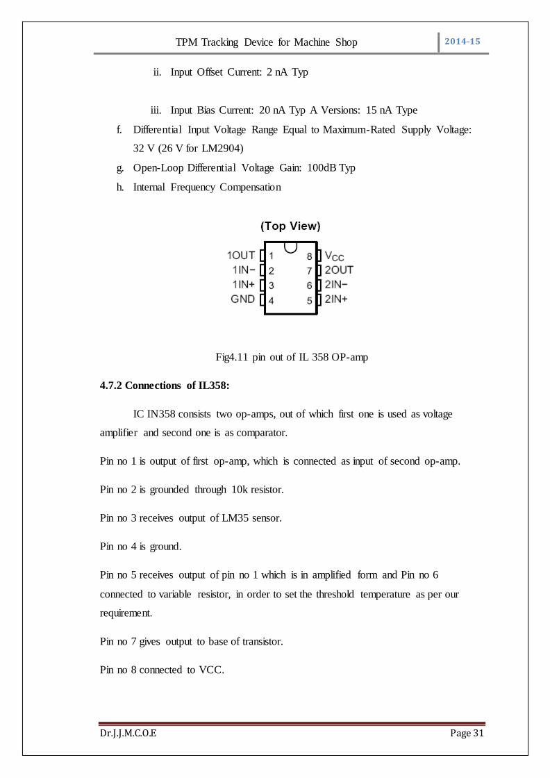
Fig4.11 pin out of IL 358 OP-amp
4.7.2 Connections of IL358:
IC IN358 consists two op-amps, out of which first one is used as voltage
amplifier and second one is as comparator.
Pin no 1 is output of first op-amp, which is connected as input of second op-amp.
Pin no 2 is grounded through 10k resistor.
Pin no 3 receives output of LM35 sensor.
Pin no 4 is ground.
Pin no 5 receives output of pin no 1 which is in amplified form and Pin no 6
connected to variable resistor, in order to set the threshold temperature as per our
requirement.
Pin no 7 gives output to base of transistor.
Pin no 8 connected to VCC.
TPM Tracking Device for Machine Shop 2014-15
Dr.J.J.M.C.O.E Page 32
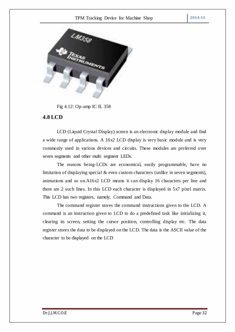
Fig 4.12: Op-amp IC IL 358
4.8 LCD
LCD (Liquid Crystal Display) screen is an electronic display module and find
a wide range of applications. A 16x2 LCD display is very basic module and is very
commonly used in various devices and circuits. These modules are preferred over
seven segments and other multi segment LEDs.
The reasons being-LCDs are economical, easily programmable, have no
limitation of displaying special & even custom characters (unlike in seven segments),
animations and so on.A16x2 LCD means it can display 16 characters per line and
there are 2 such lines. In this LCD each character is displayed in 5x7 pixel matrix.
This LCD has two registers, namely, Command and Data.
The command register stores the command instructions given to the LCD. A
command is an instruction given to LCD to do a predefined task like initializing it,
clearing its screen, setting the cursor position, controlling display etc. The data
register stores the data to be displayed on the LCD. The data is the ASCII value of the
character to be displayed on the LCD

TPM Tracking Device for Machine Shop 2014-15
Dr.J.J.M.C.O.E Page 33
Fig. 4.13: LCD Display
4.8.1 Pin description
Pin
No Function Name
1 Ground (0V) Ground
2 Supply voltage; 5V (4.7V – 5.3V) Vcc
3 Contrast adjustment; through a variable resistor VEE
4 Selects command register when low; and data register when high
Register Select
5 Low to write to the register; High to read from the register
Read/write
6 Sends data to data pins when a high to low pulse is given Enable
7
8-bit data pins
DB0
8 DB1
9 DB2
10 DB3
11 DB4
12 DB5
13 DB6
14 DB7
15 Backlight VCC (5V) Led+
16 Backlight Ground (0V) Led-
Table No 4.4: Pin Functions of LCD

TPM Tracking Device for Machine Shop 2014-15
Dr.J.J.M.C.O.E Page 34

TPM Tracking Device for Machine Shop 2014-15
Dr.J.J.M.C.O.E Page 35
4.9 Temperature Sensor IC LM35:
The LM35 series are precision integrated-circuit temperature devices with an
output voltage linearly-proportional to the Centigrade temperature. The LM35 device
has an advantage over linear temperature sensors calibrated in Kelvin, as the user is
not required to subtract a large constant voltage from the output to obtain convenient
Centigrade scaling.
Fig no 4.14: Temperature sensor IC LM35
4.9.1 Features
a. Calibrated Directly in Celsius (Centigrade)
b. Linear + 10-mV/°C Scale Factor
c. 0.5°C Ensured Accuracy (at 25°C)
d. Rated for Full −55°C to 150°C Range
e. Suitable for Remote Applications
f. Low-Cost Due to Wafer-Level Trimming
g. Operates from 4 V to 30 V
h. Less than 60-μA Current Drain
i. Low Self-Heating, 0.08°C in Still Air
j. Non-Linearity Only ±¼°C Typical
k. Low-Impedance Output, 0.1 Ω for 1-mA Load
TPM Tracking Device for Machine Shop 2014-15
Dr.J.J.M.C.O.E Page 36
4.9.2 Pin Description and Function:
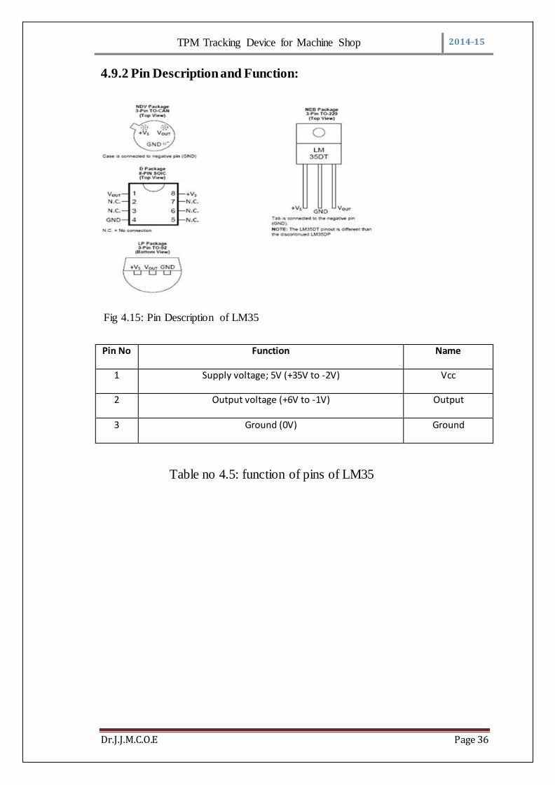
Fig 4.15: Pin Description of LM35
Pin No Function Name
1 Supply voltage; 5V (+35V to -2V) Vcc
2 Output voltage (+6V to -1V) Output
3 Ground (0V) Ground
Table no 4.5: function of pins of LM35
TPM Tracking Device for Machine Shop 2014-15
Dr.J.J.M.C.O.E Page 37
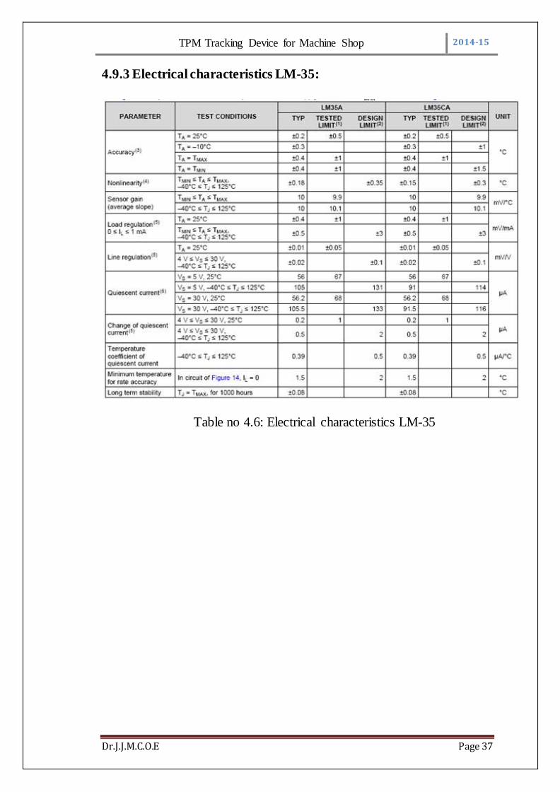
4.9.3 Electrical characteristics LM-35:
Table no 4.6: Electrical characteristics LM-35

TPM Tracking Device for Machine Shop 2014-15
Dr.J.J.M.C.O.E Page 38
4.10 Voltage Regulator IC 78XX series:
It is a three terminal positive regulator available in TO-220 package as shown
in fig 5.4.1 with several fixed output voltages. It employs internal current limiting,
thermal shut down and safe operating area protection as shown in table 5.2.
4.10.1 Features:
Output current up to 1A
Output voltages- 5, 6, 8, 9, 12, 15, 18, 24 V
Thermal Overload Protection
Short Circuit Protection
Output Transistor Safe Operating Area.
Fig. 4.16 IC 7805 Pin diagram
Fig 4.17: IC 7805 Block Diagram

TPM Tracking Device for Machine Shop 2014-15
Dr.J.J.M.C.O.E Page 39
4. 11 MAX 232-
The MAX232 device is a dual driver/receiver that includes a capacitive
voltage generator to supply EIA-232 voltage levels from a single 5-V supply. Each
receiver converts EIA-232 inputs to 5-V TTL/CMOS levels. These receivers have a
typical threshold of 1.3 V and a typical hysteresis of 0.5 V, and can accept ±30-V
inputs. Each driver converts TTL/CMOS input levels into EIA-232 levels. The driver,
receiver, and voltage-generator functions are available as cells in the Texas
Instruments LinASICE library. The MAX232 is characterized for operation from 0°C
to 70°C. The MAX232I is characterized for operation from –40°C to 85°C.
4.11.1 Features:
a. Operates With Single 5-V Power Supply
b. LinBiCMOSE Process Technology
c. Two Drivers and Two Receivers
d. ±30-V Input Levels
e. Low Supply Current . . . 8 mA Typical
f. Meets or Exceeds TIA/EIA-232-F and ITU
g. Recommendation V.28
h. Designed to be Interchangeable With Maxim MAX232
i. Applications
I. TIA/EIA-232-F
II. Battery-Powered Systems
III. Terminals
IV. Modems
V. Computers
j. ESD Protection Exceeds 2000 V Per MIL-STD-883, Method 3015
k. Package Options Include Plastic Small-Outline (D, DW) Packages
and Standard Plastic (N) DIPs
TPM Tracking Device for Machine Shop 2014-15
Dr.J.J.M.C.O.E Page 40
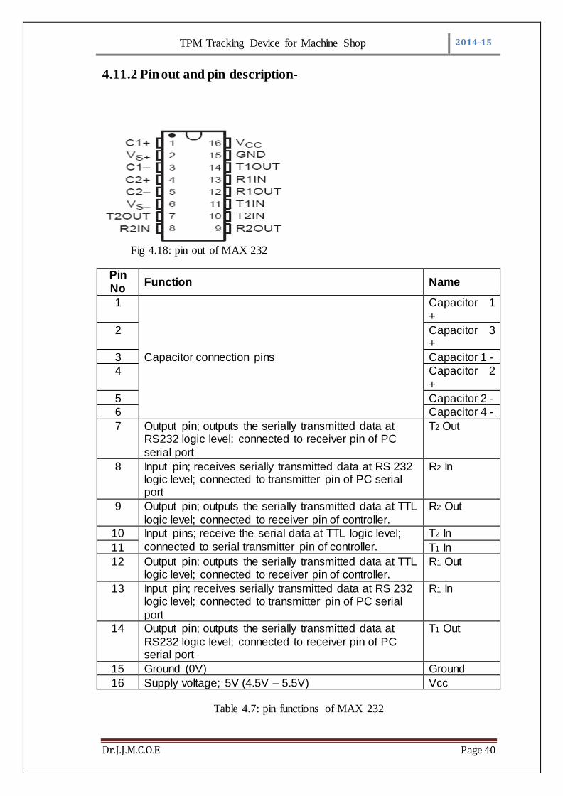
4.11.2 Pin out and pin description-
Fig 4.18: pin out of MAX 232
Pin
No Function Name
1
Capacitor connection pins
Capacitor 1
+
2 Capacitor 3 +
3 Capacitor 1 -
4 Capacitor 2
+
5 Capacitor 2 -
6 Capacitor 4 -
7 Output pin; outputs the serially transmitted data at RS232 logic level; connected to receiver pin of PC
serial port
T2 Out
8 Input pin; receives serially transmitted data at RS 232 logic level; connected to transmitter pin of PC serial port
R2 In
9 Output pin; outputs the serially transmitted data at TTL
logic level; connected to receiver pin of controller.
R2 Out
10 Input pins; receive the serial data at TTL logic level;
connected to serial transmitter pin of controller.
T2 In
11 T1 In
12 Output pin; outputs the serially transmitted data at TTL logic level; connected to receiver pin of controller.
R1 Out
13 Input pin; receives serially transmitted data at RS 232 logic level; connected to transmitter pin of PC serial
port
R1 In
14 Output pin; outputs the serially transmitted data at
RS232 logic level; connected to receiver pin of PC serial port
T1 Out
15 Ground (0V) Ground
16 Supply voltage; 5V (4.5V – 5.5V) Vcc
Table 4.7: pin functions of MAX 232
TPM Tracking Device for Machine Shop 2014-15
Dr.J.J.M.C.O.E Page 41
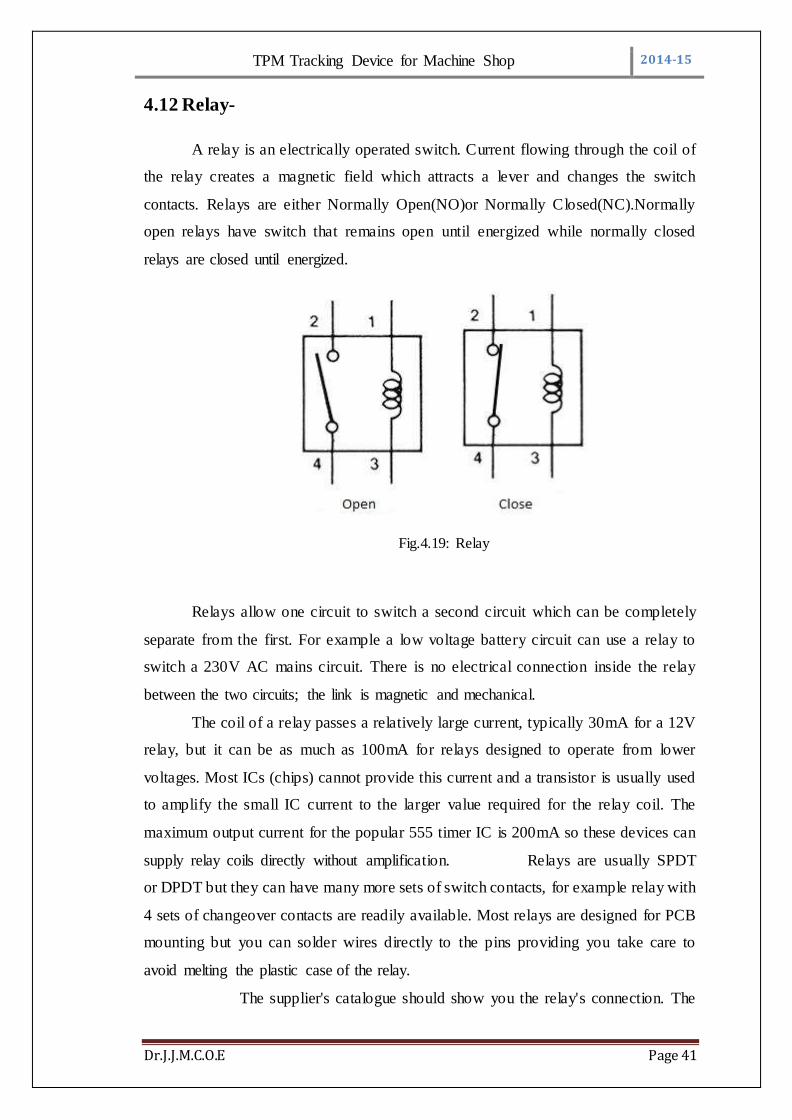
4.12 Relay-
A relay is an electrically operated switch. Current flowing through the coil of
the relay creates a magnetic field which attracts a lever and changes the switch
contacts. Relays are either Normally Open(NO)or Normally Closed(NC).Normally
open relays have switch that remains open until energized while normally closed
relays are closed until energized.
Fig.4.19: Relay
Relays allow one circuit to switch a second circuit which can be completely
separate from the first. For example a low voltage battery circuit can use a relay to
switch a 230V AC mains circuit. There is no electrical connection inside the relay
between the two circuits; the link is magnetic and mechanical.
The coil of a relay passes a relatively large current, typically 30mA for a 12V
relay, but it can be as much as 100mA for relays designed to operate from lower
voltages. Most ICs (chips) cannot provide this current and a transistor is usually used
to amplify the small IC current to the larger value required for the relay coil. The
maximum output current for the popular 555 timer IC is 200mA so these devices can
supply relay coils directly without amplification. Relays are usually SPDT
or DPDT but they can have many more sets of switch contacts, for example relay with
4 sets of changeover contacts are readily available. Most relays are designed for PCB
mounting but you can solder wires directly to the pins providing you take care to
avoid melting the plastic case of the relay.
The supplier's catalogue should show you the relay's connection. The
TPM Tracking Device for Machine Shop 2014-15
Dr.J.J.M.C.O.E Page 42
coil will be obvious and it may be connected either way round. Relay coils produce
brief high voltage 'spikes' when they are switched off and this can destro y transistors
and ICs in the circuit. To prevent damage you must connect a protection diode across
the relay coil.
The relay’s switch connections are usually contains COM, NC and NO.
COM = Common, always connect to this; it is the moving part of the switch.
NC = Normally Closed, COM is connected to this when the relay coil is off.
NO = Normally Open, COM is connected to this when the relay coil is on.
Connect to COM and NO if you want the switched circuit to be on when the relay coil
is on. Connect to COM and NC if you want the switched circuit to be on when the
relay coil is off.
4.12.1 Advantages of Relay:
Relays can switch AC and DC, transistors can only switch DC.
Relays can switch high voltages, transistors cannot.
Relays are a better choice for switching large currents (> 5A).
Relays can switch many contacts at once

TPM Tracking Device for Machine Shop 2014-15
Dr.J.J.M.C.O.E Page 43
CHAPTER 5
Software Implimentation
TPM Tracking Device for Machine Shop 2014-15
Dr.J.J.M.C.O.E Page 44
CHAPTER 5
Software Implimentation:
5.1 Software used-
5.1.1About VB.net-
Visual Basic was initially introduced in 1991 as the first programming
language that directly supported programmable graphical user interfaces using
language-supplied objects. From that time until 2002, there were five other versions
released, each version having features that increased the power of the language. In
2001, Microsoft released the .NET (pronounced “dot net”) platform. Visual Basic
.NET, or VB.NET, is an upgrade to the last version of VB (version 6.0) that conforms
to the .NET platform. The changes in VB.NET allow programmers to write Web or
desk-top applications within the same language. In addition, VB.NET is fully object-
oriented as opposed to prior versions that had many, but not all, of the elements of an
object-oriented language. [10]
From a programming viewpoint, Visual Basic is an object-oriented language
that consists of two fundamental parts: a visual part and a language part. The visual
part of the language consists of a set of objects, while the language part consists of a
high- level procedural programming language. These two elements of the language are
used together to create applications. An application is simply a Visual Basic program
that can be run under the Windows operating system. The term application is
preferred to the term program for two reasons: one, it is the term selected by
Microsoft to designate any program that can be run under its Windows Operating
System (all versions) and two, it is used to avoid confusion with older procedural
programs that consisted entirely of only a language element.[10]
TPM Tracking Device for Machine Shop 2014-15
Dr.J.J.M.C.O.E Page 45
Fig 5.1:Starting window of VB
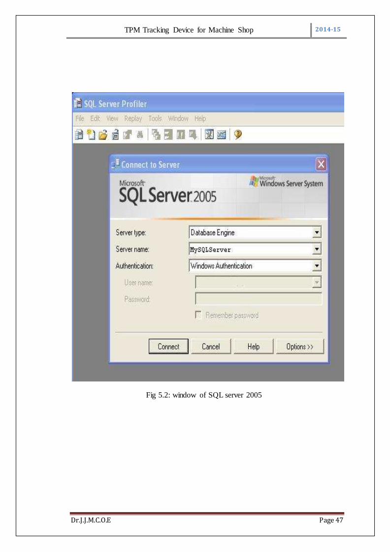
5.1.2 about sql:
SQL Server provides a number of tools that serve different purposes, such as
installation, database query, and replication. All these tools have user- friendly
graphical interfaces. Microsoft SQL Server is a relational database management
system developed by Microsoft. As a database, it is a software product whose primary
function is to store and retrieve data as requested by other software applications, be it
those on the same computer or those running on another computer across a network
(including the Internet).[11]
5.1.2.1 SQL Server 2005:
SQL Server 2005 (formerly codenamed "Yukon") released in October 2005. It
included native support for managing XML data, in addition to relational data. For
this purpose, it defined an xml data type that could be used either as a data type in
database columns or as literals in queries. XML columns can be associated with XSD
schemas; XML data being stored is verified against the schema. XML is converted to
an internal binary data type before being stored in the database. Specialized indexing
methods were made available for XML data. XML data is queried using XQuery;
SQL Server 2005 added some extensions to the T-SQL language to allow embedding
XQuery queries in T-SQL. In addition, it also defines a new extension to XQuery,
called XML DML, that allows query-based modifications to XML data. SQL Server
2005 also allows a database server to be exposed over web services using Tabular

TPM Tracking Device for Machine Shop 2014-15
Dr.J.J.M.C.O.E Page 46
Data Stream (TDS) packets encapsulated within SOAP (protocol) requests. When the
data is accessed over web services, results are returned as XML.
Common Language Runtime (CLR) integration was introduced with this
version, enabling one to write SQL code as Managed Code by the CLR. For relational
data, T-SQL has been augmented with error handling features (try/catch) and support
for recursive queries with CTEs (Common Table Expressions). SQL Server 2005 has
also been enhanced with new indexing algorithms, syntax and better error recovery
systems. Data pages are checksummed for better error resiliency, and optimistic
concurrency support has been added for better performance. Permissions and access
control have been made more granular and the query processor handles concurrent
execution of queries in a more efficient way. Partitions on tables and indexes are
supported natively, so scaling out a database onto a cluster is easier. SQL CLR was
introduced with SQL Server 2005 to let it integrate with the .NET Framework.
SQL Server 2005 introduced Multi-Version Concurrency Control. User facing
features include new transaction isolation level called SNAPSHOT and a variation of
the READ COMMITTED isolation level based on statement-level data snapshots.
SQL Server 2005 introduced "MARS" (Multiple Active Results Sets), a
method of allowing usage of database connections for multiple purposes.
SQL Server 2005 introduced DMVs (Dynamic Management Views), which are
specialized views and functions that return server state information that can be used to
monitor the health of a server instance, diagnose problems, and tune performance.
Service Pack 1 (SP1) of SQL Server 2005 introduced Database Mirroring,[Note
1][10] a high availability option that provides redundancy and failover capabilities at the
database level. Failover can be performed manually or can be configured for
automatic failover. Automatic failover requires a witness partner and an operating
mode of synchronous (also known as high-safety or full safety). [11]
TPM Tracking Device for Machine Shop 2014-15
Dr.J.J.M.C.O.E Page 47
Fig 5.2: window of SQL server 2005
TPM Tracking Device for Machine Shop 2014-15
Dr.J.J.M.C.O.E Page 48
START
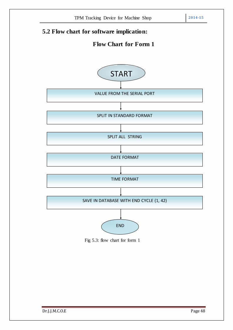
5.2 Flow chart for software implication:
Flow Chart for Form 1
Fig 5.3: flow chart for form 1
VALUE FROM THE SERIAL PORT
SPLIT IN STANDARD FORMAT
SPLIT ALL STRING
DATE FORMAT
TIME FORMAT
SAVE IN DATABASE WITH END CYCLE (1, 42)
END

TPM Tracking Device for Machine Shop 2014-15
Dr.J.J.M.C.O.E Page 49
5.2.1 Operation:
When the data is received from AVR through ETHERNET. That data is in
form of string .that string is captured in our software which is created using VB.net.
Software separates that string and fills that string into their corresponding block. So
that anyone can understand that string.
That separated string is transmitted to sql software, where that string is stored into
database.
Fig 5.4: window of frame 1
TPM Tracking Device for Machine Shop 2014-15
Dr.J.J.M.C.O.E Page 50
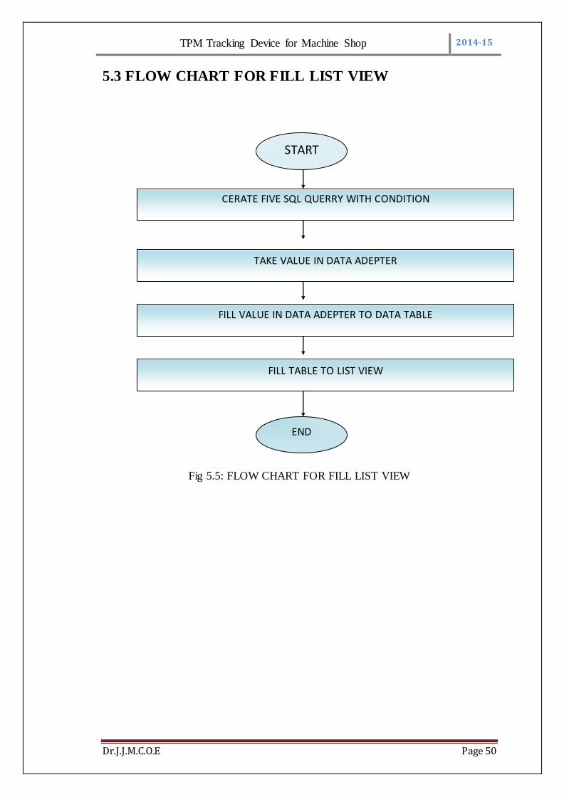
5.3 FLOW CHART FOR FILL LIST VIEW
Fig 5.5: FLOW CHART FOR FILL LIST VIEW
CERATE FIVE SQL QUERRY WITH CONDITION
TAKE VALUE IN DATA ADEPTER
FILL VALUE IN DATA ADEPTER TO DATA TABLE
FILL TABLE TO LIST VIEW
START
END

TPM Tracking Device for Machine Shop 2014-15
Dr.J.J.M.C.O.E Page 51
5.3.1 Operation:
Create 5 sql queries in sql software with solution and data adapter for storing
separated string from VB.net. fill separated string to their corresponding blocks. Data
table will take that separated string from data adapter so that one can retrieve that
whenever it is required.
Fig 5.6: window of creation of table

TPM Tracking Device for Machine Shop 2014-15
Dr.J.J.M.C.O.E Page 52
Fig 5.7: window of table filled with data

TPM Tracking Device for Machine Shop 2014-15
Dr.J.J.M.C.O.E Page 53
5.4 FLOW CHART FOR REPORT
Fig 5.8: FLOW CHART FOR REPORT
5.4.1 Operation:
Create data set and add separated string from list view. Give data set values
for creating crystal report. When we refresh crystal report it will give us graphical
representation of data.
Procedure for creating crystal report:
a. Open Visual Studio .NET and select a new Visual Basic .NET Project.
b. Create a new Crystal Report from the database
ADD VALUE IN DATA SET FROM LIST VIEW
GIVE DATA SET VALUE FOR REPORT
CALL REPORT IN CRYSTAL REPORT VIEWER
REFRESH CRYSTAL REPORT
START
END

TPM Tracking Device for Machine Shop 2014-15
Dr.J.J.M.C.O.E Page 54
c. From main menu in Visual Studio select PROJECT-->Add New Item . Then
Add New Item dialogue will appear and select Crystal Reports from the
dialogue box
d. Select Report type from Crystal Reports gallery.
e. select the appropriate connection to your database.
i. For example: Select OLE DB (ADO) from Create New
Connection
f. Select Microsoft OLE DB Provider for SQL Server.
g. Then you will get your Server name under OLEDB Connection from there
select database name (Crystaldb) and click the tables , then you can see all
your tables from your database.
h. From the tables list select Product table to the right side list .
i. Select all fields from table to the right side list
Fig 5.9: window of graphical representation
TPM Tracking Device for Machine Shop 2014-15
Dr.J.J.M.C.O.E Page 55
CHAPTER 6
Discussion and future scopes
TPM Tracking Device for Machine Shop 2014-15
Dr.J.J.M.C.O.E Page 56
CHAPTER 6
Discussion and future scopes:
6.1 Discussion-
a. When machine get started, it will start to send strings continuously to our
device.
b. String actually consists of Date, Time, operator id, machine id, job number
and other codes for various reasons.
c. That string will be received by our device and then it is stored in internal
EEPROM of AVR. And then it is forwarded to PC through ETHERNET.
d. In pc using VB.net software, we have created one window, in which we can
separate received string into simplest form so that it can be understandable to
anyone.
e. That separated string is stored in SQL software. So that we can recover data
anytime.
f. It is also useful for detecting 3-phases connected to machine and for
controlling cooling fan system.
6.2 Advantages –
a. Visual tool for Lean Management
b. Improved production efficiency
c. Improved product quality
d. Find out the causes of malfunctions and stoppages
e. Reliable and accurate information on machine capacity usage
f. More efficient maintenance and improved equipment reliability
g. Product-specific effective production times and quantities
h. Accurate information to support investment decisions
i. Dependable information to support accounting
j. Support for OEE key figure calculation
k. Reduction of manual work
l. It helps you to reduce your manufacturing downtime
m. It connects you to all of your shop floor assets
TPM Tracking Device for Machine Shop 2014-15
Dr.J.J.M.C.O.E Page 57
n. It’s reliable
o. It’s easy, economical, and low-risk
p. It has a short payback period
6.3 Disadvantages –
a. Only three machines can be connected to one device so, for more machines more
devices are needed.
b. Cost requires for developing such device is large.
c. Higher initial cost
6.4 Application:
6.4.1 .In VMC industries-
The device is very useful in VMC industries, to monitor machine parameter
and displaying them on computer. This will avoid the manpower require for machine
maintenance and to quick identify fault in which machine
6.4.2. In automation and automobile industries –
In such industries there is huge requirement of producing large product with
higher efficiency and with good material management scheme to achieve this TPM
concept is essential.
TPM Tracking Device for Machine Shop 2014-15
Dr.J.J.M.C.O.E Page 58
6.5 Future scope and Result:
It helps you to reduce your manufacturing downtime - Downtime is your
largest barrier to profitability. When one of your machines is down for an hour, many
hours of productivity can be lost because your manufacturing processes become
unsynchronized. It’s not unusual for a company to implement TPM-Trak, act on what
is discovered, and then achieve a 10%+ improvement in OEE. That 10% improvement
can generate a 60%+ improvement in income to your bottom line! A manufacturing
plant with annual sales of $100 million recovered $5.6 million in additional income
from operations through a 10% improvement in OEE. This example is documented in
“Overall Equipment Effectiveness: A Powerful Production/Maintenance Tool for
Increased Profits
It connects you to all of your shop floor assets - TPM-Trak is a single network
to / from every machine on your shop floor. It’s separate from your existing corporate
network and it automatically collects machine performance data with very little
machine operator involvement. It can be configured to send e-mail alerts or Short
Messaging Service (SMS) texts to machine operators, maintenance personnel, or plant
managers. It can automatically inform the people who need to know when a machine
goes down or when OEE falls below acceptable values. No matter where you are, you
can still be connected to what’s happening in your shop
TPM-Trak is a single network to / from every machine on your shop floor. It’s
separate from your existing corporate network and it automatically collects machine
performance data with very little machine operator involvement. It can be configured
to send e-mail alerts or Short Messaging Service (SMS) texts to machine operators,
maintenance personnel, or plant managers. It can automatically inform the people
who need to know when a machine goes down or when OEE falls below acceptable
values. No matter where you are, you can still be connected to what’s happening in
your shop

TPM Tracking Device for Machine Shop 2014-15
Dr.J.J.M.C.O.E Page 59
6.5.1 Result
Observation
Following is total hardware view
fig6.1 :- hardware view of project
Observation table:
Sr .no. Parameter Monitoring Controlling
1
Temperature
52 ’c/ over temp
Fan ON
2
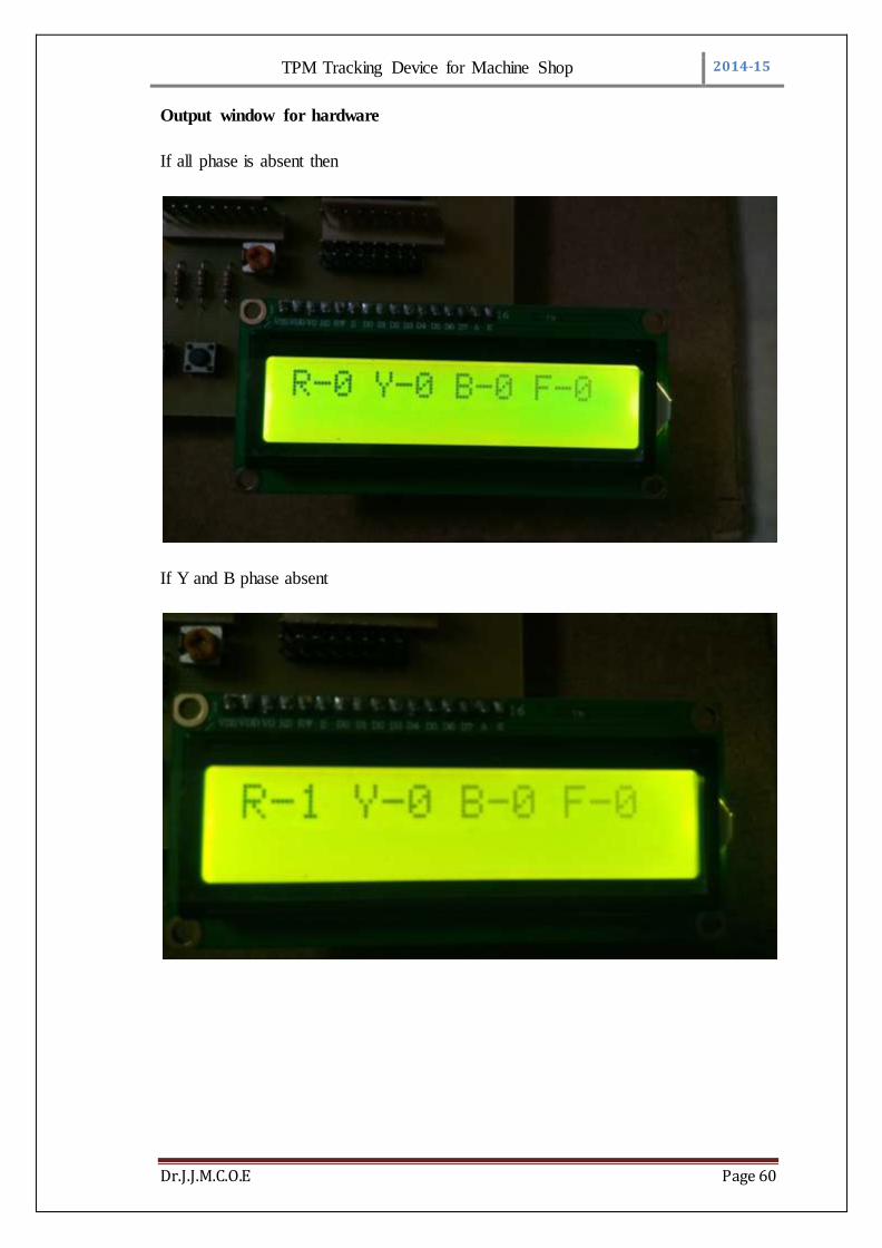
Three Phase Indication
If Phase absent
Display on LCD
TPM Tracking Device for Machine Shop 2014-15
Dr.J.J.M.C.O.E Page 60
Output window for hardware
If all phase is absent then
If Y and B phase absent

TPM Tracking Device for Machine Shop 2014-15
Dr.J.J.M.C.O.E Page 61
Through Serial port data sending to the computer
Output window for software
Data come from serial port and split into different format
TPM Tracking Device for Machine Shop 2014-15
Dr.J.J.M.C.O.E Page 62
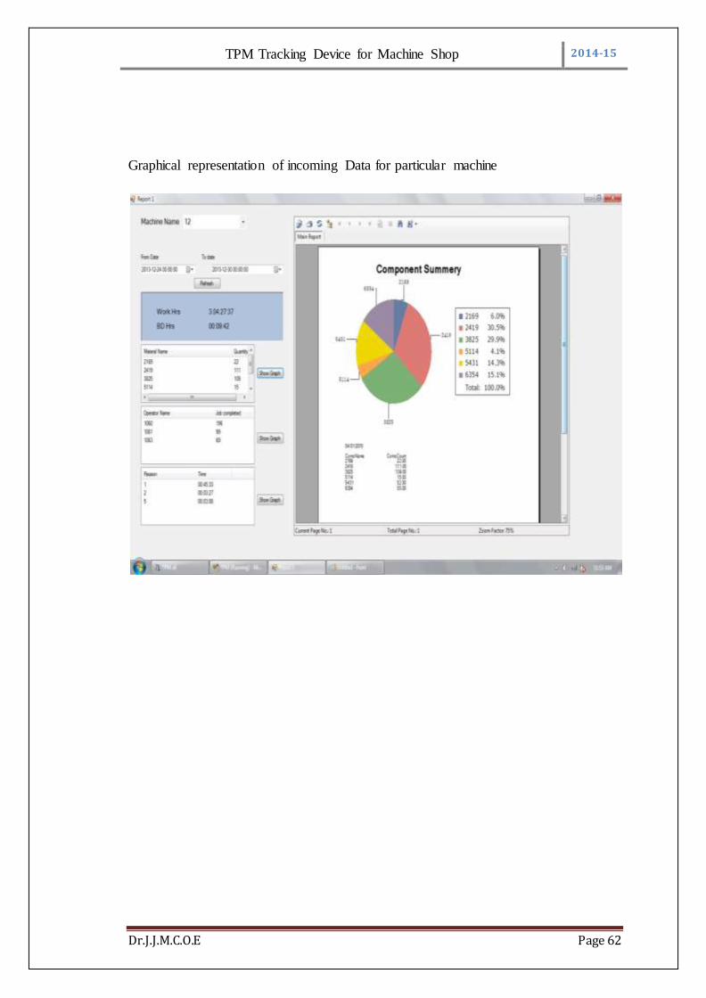
Graphical representation of incoming Data for particular machine
TPM Tracking Device for Machine Shop 2014-15
Dr.J.J.M.C.O.E Page 63
References:
1. Mr.Melesse Workneh Wakjira, Mr.Ajit Pal Singh “TOTAL PRODUCTIVE
MAINTENANCE: A CASE STUDY IN MANUFACTURING INDUSTRY”
Global Journal of researches in engineering. Industrial engineering (February
2012) Volume 12 Issue 1 Version 1.0 February 2012
2. Ahuja, I.P.S. & Khamba, J.S. (2007). “An evaluation of TPM implementation
initiatives in an Indian manufacturing enterprise”. Journal of Quality in
Maintenance Engineering 13(4), 338-52.
3. Mr. Sharma Kumar Rajiv& Mrs. Sharma Pooja “COMPUTING RAM
INDICES FOR RELIABLE OPERATION OF PRODUCTION SYSTEMS”
on 7th April 2012 Advances in Production Engineering & Management 7
(2012) 4, 245-254 ISSN 1854-6250 Scientific paper
4. Kathleen E. McKone “The impact of total productive maintenance practices
on manufacturing performance” Journal of management,19(2001)39-58.
5. Ajit Pal Sing “Total Productive Maintance” International Journal of
Application or Innovation in Engineering & Management (IJAIEM)vol 12,40-
50February2012.
6. Ahmed S.,Masjuki Hassan&Zahari Taha “TPM can go beyond
maintenance”Journal of Quality in Maintenance Engineering (2005)11(1),19-
42.
7. K.Arunraj,M.Maran,G.Manikandan “Benefits of TPM Implimentation”.2014
IEEE International Conference on Innovations in Engineering and Technology
(ICIET’14) volume 3,31-53March 2014.
8. P.Prakash, S.Kumar, T.Sakthieswaran “Implementation of total productive
maintenance in industry – a case study” P.A.College of Engineering and
Technology, International Journal of Engineering Trends and Technology
(IJETT) - olume4Issue4- April 2013

TPM Tracking Device for Machine Shop 2014-15
Dr.J.J.M.C.O.E Page 64
9. Muhamad ali mazidi, sarmad naimi, sepher naimi book on “The AVR
microcontroller and embedded systems”
10. Mackenzie, Duncan (2006). "Navigate The .NET Framework And Your
Projects With The My Namespace". MSDN Magazine Visual Studio 2005
Guided Tour 2006. Microsoft.
11. Lam, Rohan. "Microsoft is Aligning with ODBC for Native Relational Data
Access - FAQ". SQL Server Forums. Microsoft Corporation. Retrieved March
7, 2012
TPM Tracking Device for Machine Shop 2014-15
Dr.J.J.M.C.O.E Page 65
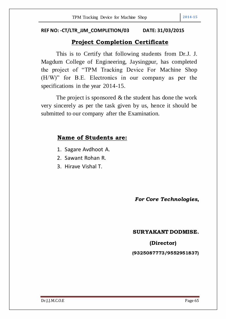
REF NO: -CT/LTR_JJM_COMPLETION/03 DATE: 31/03/2015
Project Completion Certificate
This is to Certify that following students from Dr.J. J.
Magdum College of Engineering, Jaysingpur, has completed
the project of “TPM Tracking Device For Machine Shop
(H/W)” for B.E. Electronics in our company as per the
specifications in the year 2014-15.
The project is sponsored & the student has done the work
very sincerely as per the task given by us, hence it should be
submitted to our company after the Examination.
Name of Students are:
1. Sagare Avdhoot A.
2. Sawant Rohan R.
3. Hirave Vishal T.
For Core Technologies,
SURYAKANT DODMISE.
(Director)
(9325087773/9552951837)


![Land Issues [Idam Kadam Denamuthukam] - Tamil](https://img.pdfslide.us/doc/110x75/579074651a28ab6874afb131/land-issues-idam-kadam-denamuthukam-tamil.jpg)


![[Eng1]tpm guidebook(1 4)v1-sample_hd_trien_khai-tpm](https://img.pdfslide.us/doc/110x75/58eec0431a28ab3b018b45d7/eng1tpm-guidebook1-4v1-samplehdtrienkhai-tpm.jpg)