Embed Size (px)
Citation preview

1
A REPORT ON
8 WEEKS STUDENT WORK EXPERIENCE PROGRAMME (SWEP) 2013/2014 SESSION
AT
GOD‘S WISDOM TECHNICAL WORKS (Orogun Junction, off Ojoo Express Way, Ibadan, Oyo state)
BY
ODIGIE OSAZEE
MATRIC NO: 179500
DEPARTMENT OF ELECTRICAL AND ELECTRONIC
ENGINEERING,
FACULTY OF TECHNOLOGY,
UNIVERSITY OF IBADAN,
IBADAN.
FEBRUARY TO MARCH, 2015
2
Department of Electrical/Electronic Engineering,
Faculty of Technology,
University of Ibadan,
Ibadan, Oyo State.
27th
April, 2015.
The Director,
Industrial Training Coordinating Centre,
University of Ibadan,
Ibadan.
Sir,
SUBMISSION OF INDUSTRIAL TRAINING REPORT
I use this medium to notify you that I have successfully completed the 8 weeks Student
Work Experience Programme (SWEP) for the 2013/2014 session, which commenced on the 16th
day of February, 2015 and ended on the 27th day of March, 2015 at God‘s Wisdom Technical
Works situated at Orogun Junction, Off Ojoo Expressway, Ibadan, Oyo State.
I hereby tender this submission letter alongside my industrial training report and log book
in partial fulfillment of the requirements of the SWEP programme and as required for a
successful completion of the TIT 299 course.
I greatly appreciate your effort and the effort of the Industrial Training Coordinating
Centre as a whole for making the SWEP program a success.
Yours faithfully,
Odigie Osazee
179500

3
ACKNOWLEDGEMENT
All glory and praise be to Almighty God for his favour and grace upon my life especially
in the area of my academics. He kept me safe and has given me the enablement to achieve yet
another milestone in my academic career.
I appreciate my parents, Mr and Mrs G.E. Odigie for all their support (spiritual, moral, and
financial) and for the journey so far. A special thanks to my uncles and aunties, siblings, friends
especially Awobekun Dapo, my senior colleagues and course mates, Chioma, Amina,
Oluwasheyi, Kemi, and Shalom for their continued support and encouragement.
My gratitude also goes to Mr. Wisdom Ebinum, the managing director of God‘s Wisdom
Technical Works, for his help, constructive corrections, useful advice, support and training
during the SWEP program. I also sincerely appreciate the Industrial Training Coordinating
Centre (ITCC), University of Ibadan for the SWEP programme which has given me the
opportunity to have hands-on experience and practical experience of some of the theoretical
knowledge I have learnt in school.
Finally, I sincerely appreciate the efforts of every other person who have in one way or the
other contributed to the success of my industrial training.
4
Table of Content
Title page…………………………………………………………………………………………..i
Submission Letter……………………………......………………………………………………..ii
Acknowledgement………………………….....………………………………………………….iii
Contents……………………...………..………………………………………………………….iv
Abstract…….…………………………………………………………………...…………………v
Introduction.....................................................................................................................................1
Chapter 1: AC GENERATORS, ITS ORIGIN AND HISTORY
1.1 AC Generator and Its Basic Construction……………………….……………………………5
1.2 The Working Principles of an AC Generator…….…………………………………………...6
1.3 Types of AC Generators..…………..…………………………………………………………7
1.3.1 Rotating Armature Generator……………………………………………………………….7
1.3.2 Rotating Field Generator……………………………………………………………………8
1.3.3 Poly-phase Generators………………………………………………….…………….……..9
1.4 Origin and History of AC Generators…..…………………………………………………....11
Chapter 2: ENGINE GENERATORS
2.0 Introduction ……………………….................…………………..….....…………………….13
2.1 Mode of Operation of a Typical Generator Engine...…………………………….……….…14
2.2 Two Strokes Cycle Engine……………………………………….……………………….....14
2.3 Four Stroke Cycle Engine………….………………………………………………………..16
2.4 Points to Note Before Buying a Particular Stroke Engine …….….…………………...……17
Chapter 3: SYSTEMS AND COMPONENTS OF AC GENERATORS
3.1 The Combustion System……………………………………………………………………19
3.2 The Fuel Supply System…………………………………………………………………....24
3.3 The Exhaust System………………………………………………………………………..26
3.4 The Starter System…………………………………………………………………………27
3.5 Cooling And Lubrication System………………………………………………………….28
3.6 The Lighting System………………………………………………………………………29
Chapter 4: GENERATOR FAULTS, TROUBLESHOOTING AND MAINTENANCE
4.1 Faults, their Causes and Remedies………………………………………………………..34
4.2 Troubleshooting…………………………………………………………………………..38
4.3 Maintenance of a Generator………………………………………………………………39
4.3.1 Maintenance of the New Engine………………………………………………………..39
4.3.2 Every 8 Hours of Operation…………………………………………………………….40
4.3.3 Every 100 Hours of Operation………………………………………………………….40
5
4.3.4 Every 500 Hours of Operation………………………………………………………….40
Chapter 5: TOOLS USED AND SAFETY RULES OBSERVED IN GENERATORS
WORKSHOPS
5.1 Tools Used In Generators Workshops………………………………………………….42
5.2 Safety Rules Observed In Generators Workshops……………………………………..49
Chapter 6: PRACTICAL SKILLS LEARNT DURING SWEP
6.1 Servicing of Gasoline Generator……………………………………………………….51
6.2 Replacing Piston Rings………………………………………………………………...53
6.3 Adjustment of Valve Clearance………………………………………………………..54
6.4 Air Cleaner Service……………………………………………………………………55
6.5 Fuel Sediment Cup Cleaning………………………………………………………….56
Conclusion and Recommendation………………………………………………………...57
References………………………………………………………………………………...58
6
ABSTRACT
In this report, the writer has penned down a full review of his Students’ Work Experience
Program (SWEP) which was undertaken at God’s Wisdom Technical Works. The report contains
details of practical experiences gathered during the course of the program and theoretical
principles on which such practical experiences depend, gathered from both courses taught in the
classroom and personal research.
The report generally deals on generators which are electrical machines that convert
mechanical energy to electrical energy. However, a.c. generators which are fueled by gasoline
(petrol) are mostly dealt with as this is the area of specialization in the writer’s place of
assignment. Some of the things treated in the report include the evolution, working principles,
and parts of a generator, how to troubleshoot and repair these generators.
The report is organized as follows;
The introduction deals basically on general information on SWEP, my place of assignment, and
introduces the general experience gained during the course of the program.
In Chapter 1, the origin and evolution of a.c. generators, their working principles, and types of
a.c. generators are discussed.
Chapter 2 treats in details, engine generators and its modes of operation
Chapter 3 deals with the various systems and components of an a.c. (gasoline) generator.
The various faults in an a.c. generator, their causes and remedies are discussed in Chapter 4.
Also discussed in this chapter are troubleshooting and maintenance of a generator.
In Chapter 5, the various tools used to work on the generator are discussed.
Chapter 6 discusses the various practical skills learnt during the SWEP program.
Conclusions and recommendations were finally made in areas necessary for improvement
of the SWEP program in the future. A page for references has been included for further reading
of some issues discussed in this report. Care was taken to ensure that all that is written in this
report are accurate to the writer’s best understanding.

7
INTRODUCTION
The Student Work Experience Programme (SWEP) is one designed to enable 200 level
students of the Faculty of Technology, University of Ibadan to acquire practical skills and
experience at the shop floor. It is part of the accepted practical skills training programme
approved by the National University Commission (NUC) as part of minimum academic
requirement for the award of degree in Engineering for Nigerian Universities. It was coordinated
by the Industrial Training Coordinating Centre (ITCC), University of Ibadan and lasted for 8
weeks from the 16th
of February, 2015 to 27th
of March, 2015.
The main objective of the programme is to bridge theory with practice by creating an
avenue for students to be exposed to real engineering jobs out there in the society and real time
job situations and environment. Another objective is that it prepares students for work situation
they will meet after graduation as well as expose students to work methods and various ways of
handling machinery and equipment which are not available in the school. This is to mention a
few.
My Student Work Experince Programme (TIT299) was done at God’s Wisdom Technical
Works located at Orogun Junction, Off Ojoo Express Way, Ibadan, Oyo State from the 16th
day
of February to the 27th
day of March 2015 and it was done under the supervision of Mr. Wisdom
Ebinum. God’s Wisdom Technical Works is a small scale engineering firm managed by Mr.
Wisdom Ebinum (the owner of the firm).
8
Fig. (i) The Firm’s Sign Post
The firm’s organizational structure is shown as follows:
Manager
Assistant
Manager/Sales Rep.
Apprentices
Normal IT Students
Senior
Apprentice
2 Other
Apprentices
200L ME Student
200L PE Student
Two
200L EEE Student
9
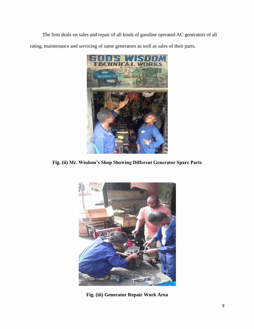
The firm deals on sales and repair of all kinds of gasoline operated AC generators of all
rating, maintenance and servicing of same generators as well as sales of their parts.
Fig. (ii) Mr. Wisdom’s Shop Showing Different Generator Spare Parts
Fig. (iii) Generator Repair Work Area

10
During the course of the program, introduction to various tools for working on a generator
was done as well as introduction to the different types of generator and their parts. Some of the
practical skills learnt include servicing alternating current (AC) generators with different models
and ratings, disassembling and reassembling of faulty a.c. generators, troubleshooting and repairs
of faults and replacing of various faulty parts of an a.c. generator.
In order to better understand the working of the generator and its parts/systems, application
of theoretical knowledge gained from classroom work as well as personal research was
necessary. Hence, I spent some time to carry out personal research and to revise some classroom
works during the course of the program.
11
CHAPTER 1
AC GENERATORS, ITS ORIGIN AND HISTORY
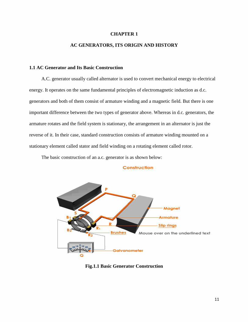
1.1 AC Generator and Its Basic Construction
A.C. generator usually called alternator is used to convert mechanical energy to electrical
energy. It operates on the same fundamental principles of electromagnetic induction as d.c.
generators and both of them consist of armature winding and a magnetic field. But there is one
important difference between the two types of generator above. Whereas in d.c. generators, the
armature rotates and the field system is stationary, the arrangement in an alternator is just the
reverse of it. In their case, standard construction consists of armature winding mounted on a
stationary element called stator and field winding on a rotating element called rotor.
The basic construction of an a.c. generator is as shown below:
Fig.1.1 Basic Generator Construction
12
1.2 The Working Principles of an AC Generator
When the magnetic coil in Fig. 2.5 above is rotating in anticlockwise direction, the coil
assumes successive positions in the field and the flux linked with it changes. Hence, an e.m.f is
induced in it which is proportional to the rate of change of flux linkages (e=-N dΦ/dt). When
the plane of the coil is at right angles to lines of flux, the flux linked with the coil is maximum
but rate of change of flux linkages is minimum.
It is so because in this position, the coil sides do not cut or shear the flux, rather they slide
along them i.e. they move parallel to them. Hence, there is no induced e.m.f in the coil.
Generally, this zero e.m.f is taken as the starting position (zero degrees position). The angle of
rotation or time will be measured from this position.
As the coil continues rotating further, the rate of change of flux linkages (and hence
induced e.m.f in it) increases till the coil rotates 90° from its starting position. Here the coil plane
is vertical i.e. parallel to the lines of flux. In this position, minimum flux is linked with the coil
but the rate of change of flux linkages is maximum. Hence, maximum e.m.f is induced in the coil
when in this position.
In the next quarter revolution i.e. from 90° to 180°,the flux linked with the coil gradually
increases but the rate of change of flux linkages decreases. Hence, induced e.m.f decreases
gradually till it becomes zero. In the next half revolution i.e. from 180° to 360°, the variations in
the magnitude of e.m.f are similar to those in the first half revolution. Maximum value is
obtained when coil is at 270° and minimum when the coil is at 360° position. But it will be found
that the direction of induced current is reverse of the previous direction of flow.
Therefore, we find that the current which we obtain from the AC generator reverses its
direction after every half revolution. Such a current undergoing periodic reversals is known as
alternating current. It should be noted that alternating current not only reverses its direction,
13
it does not even keep its magnitude constant while flowing in any one direction. The two half-
cycles may be called positive and negative half-cycles respectively.
1.3 Types of AC Generators
Various types of alternating current generators are utilized today; however, they all
perform the same basic function. The types discussed in the following paragraphs are typical of
the more predominant ones in use.
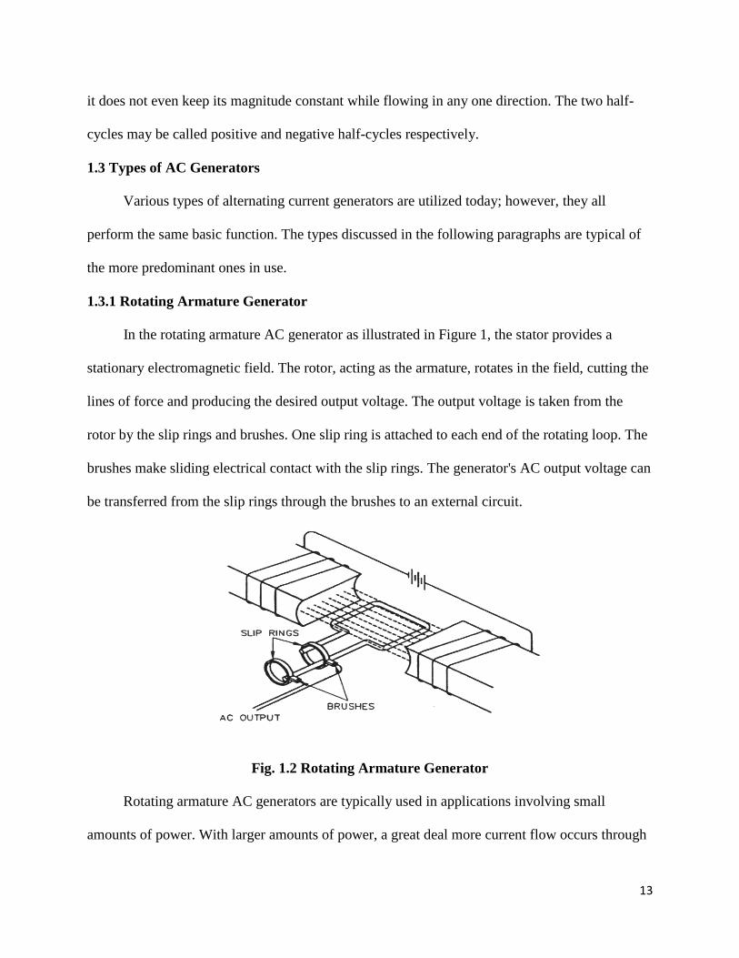
1.3.1 Rotating Armature Generator
In the rotating armature AC generator as illustrated in Figure 1, the stator provides a
stationary electromagnetic field. The rotor, acting as the armature, rotates in the field, cutting the
lines of force and producing the desired output voltage. The output voltage is taken from the
rotor by the slip rings and brushes. One slip ring is attached to each end of the rotating loop. The
brushes make sliding electrical contact with the slip rings. The generator's AC output voltage can
be transferred from the slip rings through the brushes to an external circuit.
Fig. 1.2 Rotating Armature Generator
Rotating armature AC generators are typically used in applications involving small
amounts of power. With larger amounts of power, a great deal more current flow occurs through
14
the slip rings and brushes. It is difficult and expensive to build slip rings and brushes to carry
large amounts of current. Therefore, most large AC generators are rotating field generators.
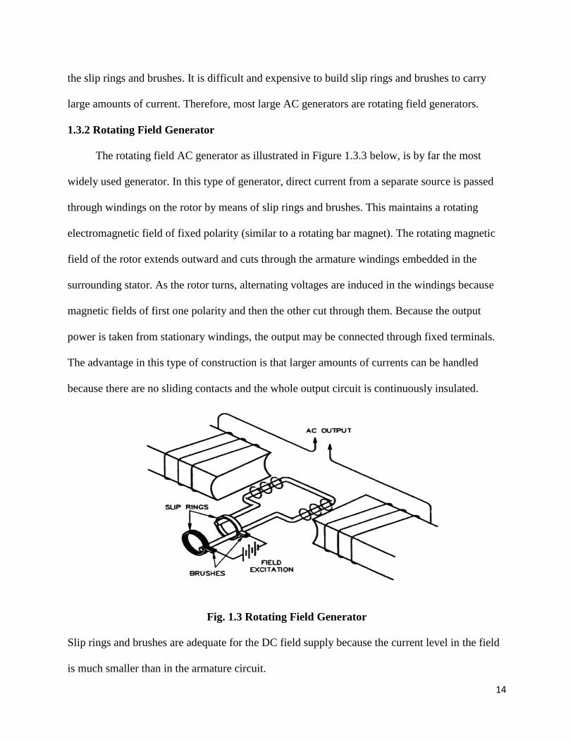
1.3.2 Rotating Field Generator
The rotating field AC generator as illustrated in Figure 1.3.3 below, is by far the most
widely used generator. In this type of generator, direct current from a separate source is passed
through windings on the rotor by means of slip rings and brushes. This maintains a rotating
electromagnetic field of fixed polarity (similar to a rotating bar magnet). The rotating magnetic
field of the rotor extends outward and cuts through the armature windings embedded in the
surrounding stator. As the rotor turns, alternating voltages are induced in the windings because
magnetic fields of first one polarity and then the other cut through them. Because the output
power is taken from stationary windings, the output may be connected through fixed terminals.
The advantage in this type of construction is that larger amounts of currents can be handled
because there are no sliding contacts and the whole output circuit is continuously insulated.
Fig. 1.3 Rotating Field Generator
Slip rings and brushes are adequate for the DC field supply because the current level in the field
is much smaller than in the armature circuit.
15
1.3.3 Poly-phase Generators
Most electric power is generated and distributed as three-phase rather than single-phase
power for the following reasons:
The cost of transmission is less than for the same voltage and power in a single-phase
system.
A three-phase generator has a 180% greater capacity than a single phase generator of the
same physical size.
Single-phase voltage and power is easily available from a three-phase system by merely
tapping any two of the power leads.
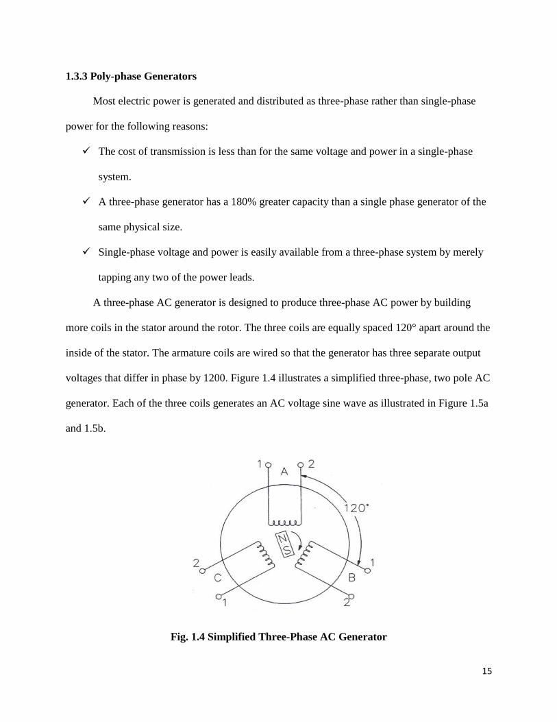
A three-phase AC generator is designed to produce three-phase AC power by building
more coils in the stator around the rotor. The three coils are equally spaced 120° apart around the
inside of the stator. The armature coils are wired so that the generator has three separate output
voltages that differ in phase by 1200. Figure 1.4 illustrates a simplified three-phase, two pole AC
generator. Each of the three coils generates an AC voltage sine wave as illustrated in Figure 1.5a
and 1.5b.
Fig. 1.4 Simplified Three-Phase AC Generator
16
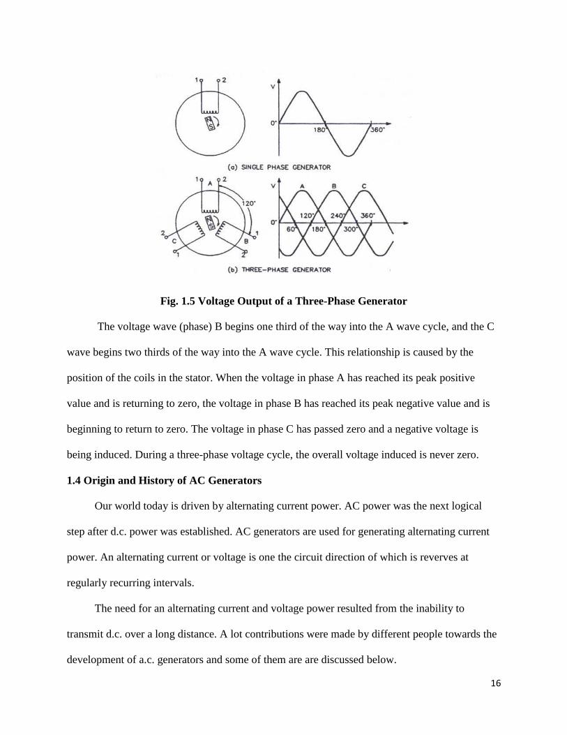
Fig. 1.5 Voltage Output of a Three-Phase Generator
The voltage wave (phase) B begins one third of the way into the A wave cycle, and the C
wave begins two thirds of the way into the A wave cycle. This relationship is caused by the
position of the coils in the stator. When the voltage in phase A has reached its peak positive
value and is returning to zero, the voltage in phase B has reached its peak negative value and is
beginning to return to zero. The voltage in phase C has passed zero and a negative voltage is
being induced. During a three-phase voltage cycle, the overall voltage induced is never zero.
1.4 Origin and History of AC Generators
Our world today is driven by alternating current power. AC power was the next logical
step after d.c. power was established. AC generators are used for generating alternating current
power. An alternating current or voltage is one the circuit direction of which is reverves at
regularly recurring intervals.
The need for an alternating current and voltage power resulted from the inability to
transmit d.c. over a long distance. A lot contributions were made by different people towards the
development of a.c. generators and some of them are are discussed below.
17
1835 - Hippolyte Pixii builds the first alternator. Pixii builds a device with a rotating magnet. He
doesn't know how to make his creation useful since all the other experimenters of the time were
building d.c. devices. Others like Faraday and Henry were experimenting at the time with
primitive electric motors using electromagnets.
1855 - Guillaume Duchenne uses alternating current in electrotherapeutic triggering of muscle
contractions. (Paris, France) a.c. power is not viewed as useful for anything else at the time.
1878 - Ganz Company starts working with single phase a.c. power systems in Budapest, Austro-
Hungary
1879 - London: Walter Baily makes a copper disc rotate using alternating current (this is a weak
early a.c. motor) which was not effective for bearing any load.
1882 - J.E.H. Gordon, a British electrician built large two-phase alternating current generators.
1887 - C.S. Bradley builds the first a.c. 3 phase generator. Up until this time Siemens and
Westinghouse had been producing single phase a.c. generators. The 3 phase system would be a
great improvement.
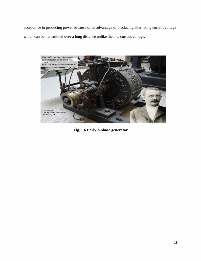
1887 - F. Augus Haselwander develops the first a.c. 3 phase generator in Europe. He is behind
Bradley by a couple months and it is generally believed that he built his design independently of
Bradley.
1888 - Mikhail Dolivo-Dobrovsky in Germany builds his first a.c. polyphase generator.
1891 - Nikola Tesla patented a practical "high-frequency" alternator (which operated around
15 kHz).
After 1891, polyphase alternators were introduced to supply currents of multiple differing
phases. Later alternators were designed for varying alternating-current frequencies between
sixteen and about one hundred hertz, for use with arc lighting, incandescent lighting and electric
motors. Ever since then, a.c. generators have become more useful especially after gaining
18
acceptance in producing power because of its advantage of producing alternating current/voltage
which can be transmitted over a long distance unlike the d.c. current/voltage.
Fig. 1.6 Early 3-phase generator
19
CHAPTER 2
ENGINE GENERATORS
2.0 Introduction
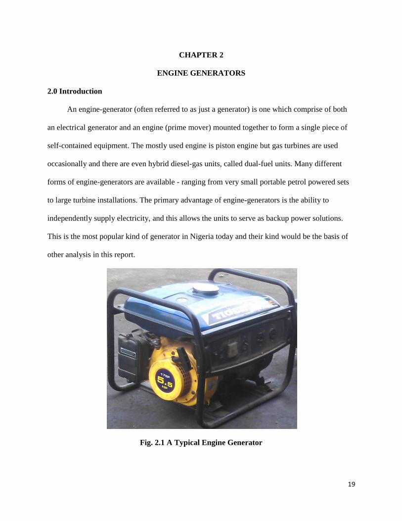
An engine-generator (often referred to as just a generator) is one which comprise of both
an electrical generator and an engine (prime mover) mounted together to form a single piece of
self-contained equipment. The mostly used engine is piston engine but gas turbines are used
occasionally and there are even hybrid diesel-gas units, called dual-fuel units. Many different
forms of engine-generators are available - ranging from very small portable petrol powered sets
to large turbine installations. The primary advantage of engine-generators is the ability to
independently supply electricity, and this allows the units to serve as backup power solutions.
This is the most popular kind of generator in Nigeria today and their kind would be the basis of
other analysis in this report.
Fig. 2.1 A Typical Engine Generator
20
2.1 Mode of Operation of a Typical Generator Engine
The needed shaft power for the alternator is supplied by the engine of the generator. The
engine comprises of the following; fuel tank, fuel pipes, carburetor (for small generator sets) or
fuel injectors (for large generator sets), cylinder, piston, connecting rods, engine block,
connecting gears and crankshaft. With small generator sets, fuel tanks are placed over the
remaining components of the generation compartment; while this may be otherwise in medium
and larger generator sets, such as placed either below or beside depending on how soonest and
faster the fuel is to reach the designated points.
In order to start a generator set, you manually pull the starter handle to rotate the
crankshaft for small generators while in large generator set, you either apply the method above or
press the on/off button or by key-starter. Before doing this, this fuel tap must have being turned
on to allow fuel to run from the fuel tank into the carburetor where the fuel is mixed with air and
the mixture supplied to the combustion chamber in the cylinder. The rotation of the crankshaft
about its linear axis makes the piston move away from the cylinder.
Considering a gasoline operated engine, the spark plug is usually hung and fitted at the
upper housing of the cylinder in a gasoline piston-cylinder compartment and is charged through
capacitors. As gasoline fuel mixture reaches the cylinder compartment, sparks are introduced by
the spark plug. Generator engines operate in either of the following below;
two stroke cycle engine
four stroke cycle engine
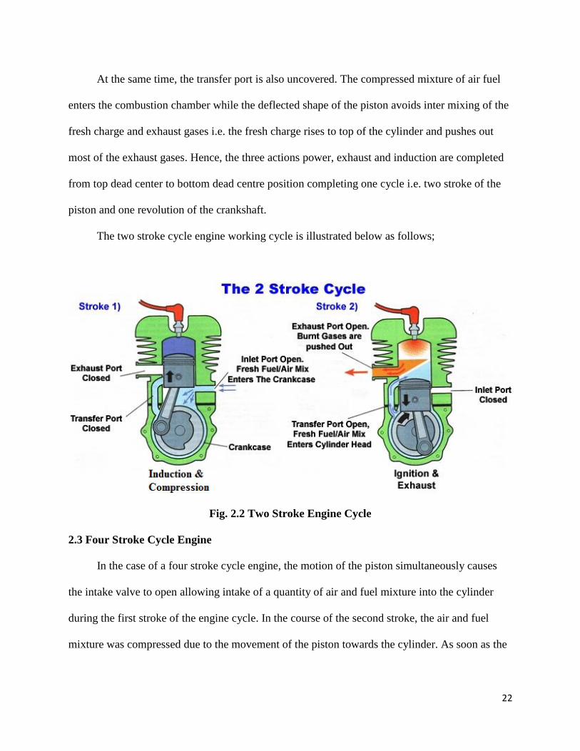
2.2 Two Strokes Cycle Engine
In a two stroke cycle petrol engine, one complete cycle comprise of two strokes of the
piston and one crankshaft revolution. In this type of engine, ports (i.e. suction port, transfer port

21
and exhaust port) are used instead of valves. The upper and downward movements of the piston
help to cover and uncover the ports. The top of the piston is deflected to avoid mixing of fresh
charge with exhaust gases. These exhaust gases are expelled out from the engine cylinder by the
fresh charge of fuel entering the cylinder.
The mixture of air and petrol is ignited by an electric spark produced at the spark plug. The
crankcase is air tight and for the lubrication of the moving parts like crankshaft, connecting
roads, cylinder liner and piston, the fuel air mixture mixed with lubricating oil is passed through
the crankcase and thus these parts are lubricated (a system known as petrol lubrication).
First Stroke: In the course of the first stroke, the inlet port is covered by piston whereas the
transfer port and exhaust port are uncovered. The Piston moves from bottom dead centre to the
top dead centre. The air fuel mixture enters the cylinder. On the upward movement of the piston,
the transfer port is covered and then immediately, the exhaust port is also covered.
Simultaneously the suction port also gets uncovered.
The upward movement of the piston helps to compress the air fuel mixture at the top and
creates partial vacuum at the bottom in the crank case which gets filled with air fuel mixture by
the atmospheric pressure. At the end of stroke, the piston reaches the top dead centre position
completing the compression stroke.
Second Stroke: As the compression stroke is being completed, the compressed charge is ignited
in the combustion chamber, by means of electric spark produced by the spark plug. Combustion
of air fuel mixture pushes the piston in the downward direction, on the power stroke producing
useful work. The moment power action is over, the exhaust port is uncovered. The exhaust gases
escapes to the atmosphere. The further movement of the piston will cover the inlet port and the
fresh charge would be compressed in the crankcase.
22
At the same time, the transfer port is also uncovered. The compressed mixture of air fuel
enters the combustion chamber while the deflected shape of the piston avoids inter mixing of the
fresh charge and exhaust gases i.e. the fresh charge rises to top of the cylinder and pushes out
most of the exhaust gases. Hence, the three actions power, exhaust and induction are completed
from top dead center to bottom dead centre position completing one cycle i.e. two stroke of the
piston and one revolution of the crankshaft.
The two stroke cycle engine working cycle is illustrated below as follows;
Fig. 2.2 Two Stroke Engine Cycle
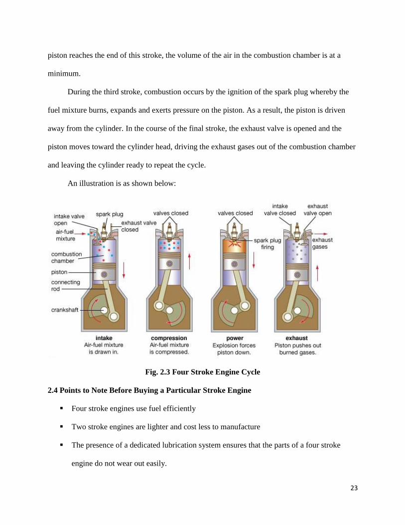
2.3 Four Stroke Cycle Engine
In the case of a four stroke cycle engine, the motion of the piston simultaneously causes
the intake valve to open allowing intake of a quantity of air and fuel mixture into the cylinder
during the first stroke of the engine cycle. In the course of the second stroke, the air and fuel
mixture was compressed due to the movement of the piston towards the cylinder. As soon as the
23
piston reaches the end of this stroke, the volume of the air in the combustion chamber is at a
minimum.
During the third stroke, combustion occurs by the ignition of the spark plug whereby the
fuel mixture burns, expands and exerts pressure on the piston. As a result, the piston is driven
away from the cylinder. In the course of the final stroke, the exhaust valve is opened and the
piston moves toward the cylinder head, driving the exhaust gases out of the combustion chamber
and leaving the cylinder ready to repeat the cycle.
An illustration is as shown below:
Fig. 2.3 Four Stroke Engine Cycle
2.4 Points to Note Before Buying a Particular Stroke Engine
Four stroke engines use fuel efficiently
Two stroke engines are lighter and cost less to manufacture
The presence of a dedicated lubrication system ensures that the parts of a four stroke
engine do not wear out easily.

24
Two stroke engines construction is simple because they do not have valves
Four stroke engines produce less pollution than two stroke engines
Two stroke engines fire once every revolution which gives it a significant power boost
Four stroke engines have a longer life span as compared to two stroke engine.
25
CHAPTER 3
SYSTEMS AND COMPONENTS OF AC GENERATORS
AC generators (whether small, medium or large in size) comprise of various systems and
components and in other to understand the working and construction of these generators, there is
need to study the individual systems and components. This is the reason for this chapter.
The systems in an a.c. generator could either be mechanical or electrical and these systems
comprise of different components which work together to ensure the proper functioning of the
system. The various systems and their components are discussed below.
3.1 The Combustion System
The engine of a generator produces mechanical force and motion from the latent chemical
energy in the fuel burnt in its combustion chamber. Hence, it is called an internal combustion
engine. Various type of generator engines are designed to operate on different variety of fuels
such as diesel, gasoline, propane (in liquefied or gaseous form), or natural gas. Smaller engines
usually operate on gasoline while larger engines run on diesel, liquid propane, propane gas, or
natural gas. Some other engines can also operate on a dual feed of diesel and gas, kerosene and
gasoline in a bi-fuel operation mode.
The cycle employed in the engine of a generator could be four-stroke or two-stroke. There
is one power stroke for every four strokes of the piston movement (up-down-up-down) for a
four-stroke piston engine. The processes are intake stroke, compression stroke, combustion
stroke and exhaust stroke. During the intake stroke, combustible mixtures are placed in the
combustion chamber and these mixtures are placed under pressure in the compression stroke.
While the mixture is burnt with the hot mixture expanded and pressing on and moving parts of
the engine to perform useful work during the power stroke. Lastly, during the exhaust stroke, the
cooled combustion products are exhausted into the atmosphere.
26
Every typical two-stroke engine has one power stroke for every two strokes of the piston
(up-down). It is an internal combustion engine that completes the thermodynamic cycle in two
movements of the piston as compared to four movements for a four-stroke engine. Efficiency is
increased and is accomplished by using the beginning of the compression stroke and the end of
the combustion stroke to perform simultaneously the intake and exhaust functions.
Two-stroke engines are having different design types which vary according to the method
of introducing the charge to the cylinder, the method of scavenging the cylinder (exchanging
burnt exhaust for fresh mixture) and the method of exhausting the cylinder. Spark-ignition two-
strokes are small and light for their power output and mechanically very simple; however, they
are also generally less efficient and more polluting than their four-stroke counterparts.
The components of the combustion system for a four-stroke engine are discussed below:
Piston: This is usually situated in the cylinder of the cylinder block and its up-down movement
is enhanced by the ignition of the spark plug and the opening and closing of the valves. It has
grooves which houses its rings which are usually equal to or greater than 2 depending on the
design of generator). A piston ring is an open-ended ring that fits into a groove on the outer
circumference of a piston in a reciprocating engine and its main functions include;
Engine oil consumption regulation.
Sealing the combustion/expansion chamber.
The support of heat transfer from the piston to the cylinder wall
A generator piston usually have 3 rings with the top two primarily meant for compression
sealing while also controlling oil and the lower ring for oil supply control to the liner which
lubricates the piston skirt and the compression rings (oil control rings).

27
Fig. 3.1 Piston with Rings, Basket Bearing, Connecting rods, and Key
Adequate supply of pressure in the combustion chamber is ensured by the piston rings.
The major problem encountered with use of piston is that carbon becomes deposited on the
piston head and its sides after being used for some time and it leads to low efficiency of
generators. But this can be fixed by removing the carbon or replacing the piston and piston rings
as we always did during my industrial training experience.
Crankshaft: This component is usually forged from steel and it is the part of the engine which
translates the reciprocating linear piston motion into rotation. In order to do, the crankshaft has
"crank throws" (additional bearing surfaces whose axis is offset from that of the crank) to which
the "big ends" of the connecting rods from the cylinder attach. It typically connects to a flywheel,
to reduce the pulsation characteristic of the four-stroke cycle, and sometimes a vibration damper
at the opposite end thereby reducing the torsion vibrations often caused along the length of the
crankshaft by the cylinders farthest from the output end which acts on the tensional elasticity of
the metal.
28
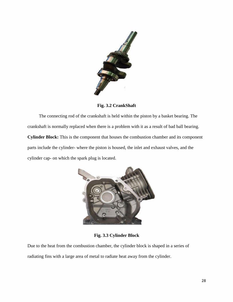
Fig. 3.2 CrankShaft
The connecting rod of the crankshaft is held within the piston by a basket bearing. The
crankshaft is normally replaced when there is a problem with it as a result of bad ball bearing.
Cylinder Block: This is the component that houses the combustion chamber and its component
parts include the cylinder- where the piston is housed, the inlet and exhaust valves, and the
cylinder cap- on which the spark plug is located.
Fig. 3.3 Cylinder Block
Due to the heat from the combustion chamber, the cylinder block is shaped in a series of
radiating fins with a large area of metal to radiate heat away from the cylinder.

29
Governor: In gasoline generators, the governor regulates the amount of fuel admitted thereby
maintaining a near constant speed no matter the load or fuel supply condition. The governor can
usually be adjusted by turning a screw attached to the governor control. Hence, the output
voltage depends on the efficiency of the governor.
Fig. 3.4 Governor
Spark Plug: The spark plug is responsible for ignition in the combustion chamber of the
cylinder and as stated above, it is located on the cylinder cap. It causes the ignition of the air and
fuel mixture from the carburetor. The spark plug is present in any internal combustion engine
that makes use of fuel because its ignition enables piston movement. It should be noted that a
red-like spark or too bright spark is not usually suitable for ignition but a blue brownish-like
spark. The spark plug is replaced with a good one when bad.
30
Fig. 3.5 Spark Plug
3.2 The Fuel Supply System
This system is one of the mechanical systems of a generator and comprises of two main
components-the fuel tank and the carburetor.
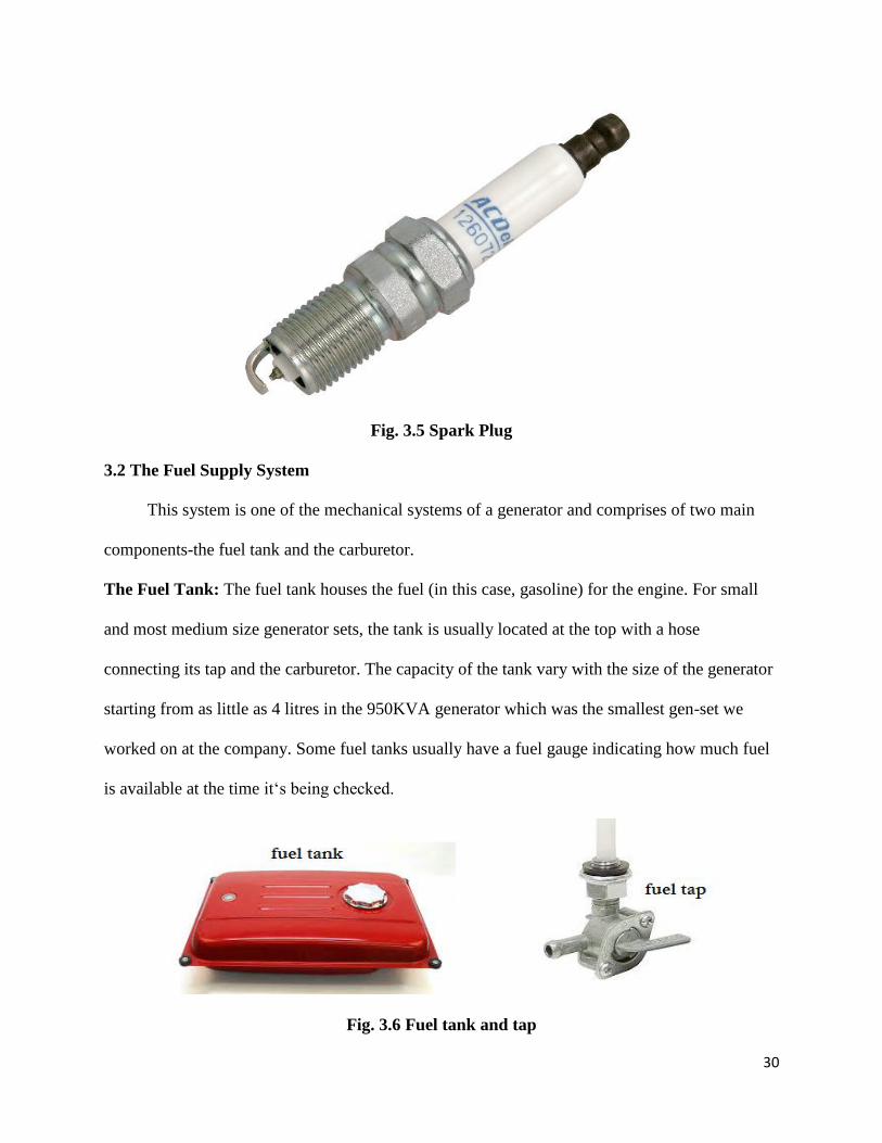
The Fuel Tank: The fuel tank houses the fuel (in this case, gasoline) for the engine. For small
and most medium size generator sets, the tank is usually located at the top with a hose
connecting its tap and the carburetor. The capacity of the tank vary with the size of the generator
starting from as little as 4 litres in the 950KVA generator which was the smallest gen-set we
worked on at the company. Some fuel tanks usually have a fuel gauge indicating how much fuel
is available at the time it‘s being checked.
Fig. 3.6 Fuel tank and tap

31
Despite the fact that the fuel tanks usually come with filters, every of the tanks could
sometimes become dirty even though they come with filters and have their capacities reduced as
a result of water at the bottom of the tank. The dirts which accumulate at the bottom of the tank
and the water are usually transferred when an empty or partially full tank is being refilled and
these could gradually fill the tap and reduce the amount of fuel reaching the carburetor or even
block the tap entirely.
In order to resolve these problems, the tank is detached from the chassis so that the tap is
removed and the content of the tank is poured into a container. The water and dirt would be seen
at the bottom of the container. By so doing, the tank is flushed. The tap/sediment cap is also
cleaned and dried. The tap is fixed to the tank and then the unit is returned to the chassis.
Carburetor: The air and fuel mixture for combustion in the cylinder block is supplied in the
correct proportion by the carburetor. Some generators make use of one carburetor while others
use fuel injectors. The liquid fuel is atomized by the injector and the required amount of fuel
sprayed into the combustion chamber of the engine. The carburetor works on Bernoulli's
principle- the faster air moves, the lower its static pressure, and the higher its dynamic pressure.
The major parts of a carburetor include the fuel inlet, float pin, float chamber, float chamber
cover, hose and choke. When fuel flows into the float chamber cover of the carburetor, it gets
filled which causes it to push the float chamber up.
Fig. 3.7 Carburetor

32
It exerts pressure on the float pin in the float chamber so that no more fuel comes into the
float chamber. The fuel evaporates through the fuel inlet to the cylinder block. When the
pressure is greatly reduced, the whole process is repeated. The choke of the carburetor plays a
vital role in starting the generator. When the engine does not start despite the starter being pulled,
it is due to the fact that fuel becomes less readily vaporizable. Hence, there is less fuel to air in
the air and fuel mixture supply to the cylinder. To provide the extra fuel, the choke is used. The
choke is a device that restricts the flow of air to the carburetor hereby enabling a rich air and fuel
mixture for ignition.
3.3 The Exhaust System
The incomplete combustion of carbonaceous fuel in the engine lead to pollution by the
emission of sulphur (IV) oxide, SO2, carbon (II) oxide, CO and so on. These air pollution
emissions might be fatal and exposure to the noise from the engine’s exhaust for a long time can
lead to loss of hearing. Therefore, the exhaust system must be installed in such a manner to
prevent its emissions from accumulating from the combustion chamber in the engine. The
exhaust system contains devices to control pollution, both chemical and noise pollution. In
addition, for cyclic combustion engines, the exhaust system is frequently tuned to improve
emptying of the combustion chamber. It is important to note that a generator must never be
operated if it does not have a full exhaust system.
Silencer: A silencer (Muffler) is a device for reducing the amount of noise emitted by the
exhaust of an internal combustion engine. Silencers are installed with the exhaust system of all
engine-generators although they not designed to serve any primary exhaust function. The
silencer is engineered as an acoustic sound proofing device designed to reduce the loudness of
the sound pressure created by the engine. This is done through destructive interference wherein
opposite sound waves cancel each other out. An unavoidable side effect of silencer use is an
33
increase of back pressure (resistance of a moving fluid) which decreases engine efficiency. This
is because the engine exhaust must share the same complex exit pathway built inside the silencer.
3.4 The Starter System
This system is part of the mechanical system of a generator and includes the following
parts:
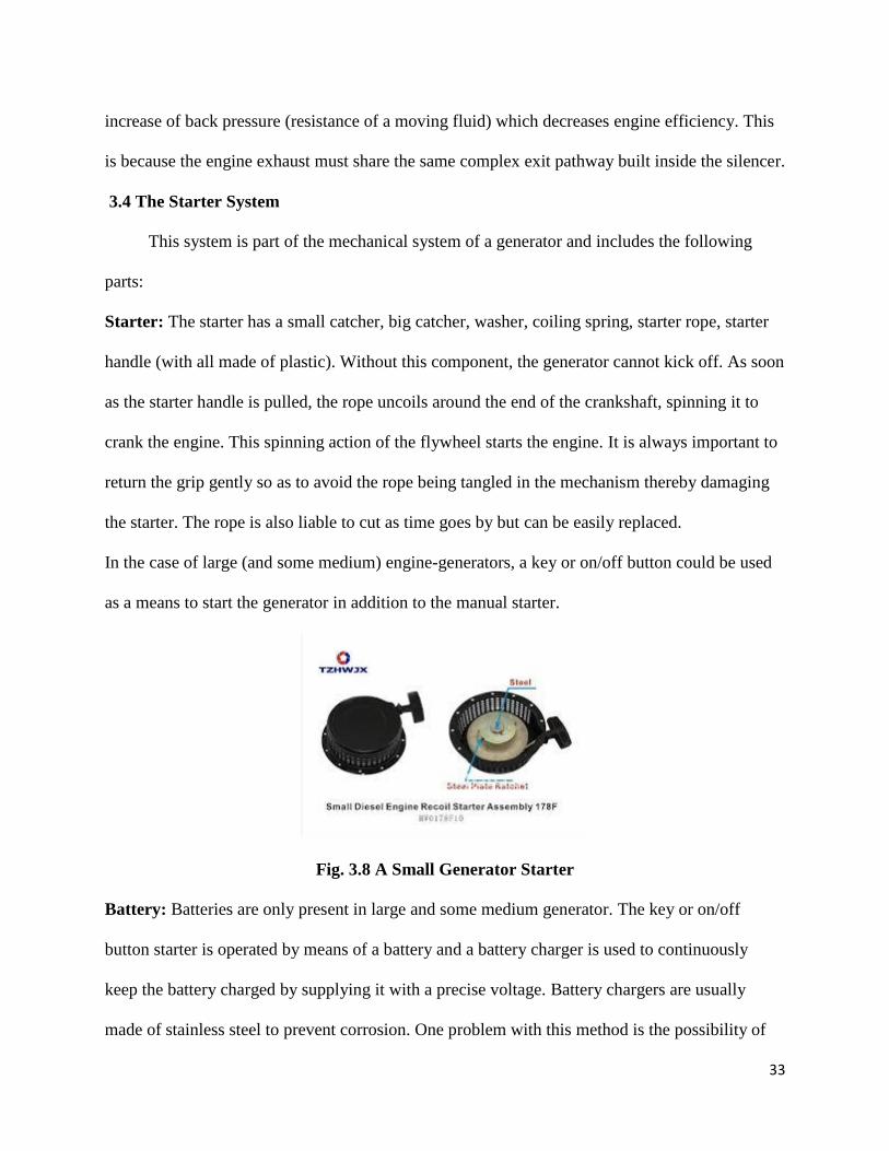
Starter: The starter has a small catcher, big catcher, washer, coiling spring, starter rope, starter
handle (with all made of plastic). Without this component, the generator cannot kick off. As soon
as the starter handle is pulled, the rope uncoils around the end of the crankshaft, spinning it to
crank the engine. This spinning action of the flywheel starts the engine. It is always important to
return the grip gently so as to avoid the rope being tangled in the mechanism thereby damaging
the starter. The rope is also liable to cut as time goes by but can be easily replaced.
In the case of large (and some medium) engine-generators, a key or on/off button could be used
as a means to start the generator in addition to the manual starter.
Fig. 3.8 A Small Generator Starter
Battery: Batteries are only present in large and some medium generator. The key or on/off
button starter is operated by means of a battery and a battery charger is used to continuously
keep the battery charged by supplying it with a precise voltage. Battery chargers are usually
made of stainless steel to prevent corrosion. One problem with this method is the possibility of

34
the battery running down. When this happens, the recoil starter would have to be used to start the
engine.
Flywheel: This is a wheel or disc attached to the crank and which forms the inertial mass that
stores rotational energy. The flywheel is essential to carry energy over from the power stroke
into a subsequent compression stroke in single cylinder engines. In reciprocating engines, the
flywheel ensures smoothening out of the power delivery over each rotation of the crank while in
most automotive engines; the flywheel is used to mount a gear ring for a starter.
3.5 Cooling And Lubrication System
As the engine of a generator continues to work, the combustion in the internal combustion
engine generates a great deal of heat and some of this heat is transferred to the walls of the
engine. If the body of the engine is allowed to reach too high a temperature, failure will occur
either as a result of the engine physically failing or any lubricants used degrading to the point
that they no longer protect the engine. This brings about the need for cooling the generator
engine.
Cooling is a very important factor as it relates to the life and performance of the generator.
Under normal conditions, such cooling can be obtained through natural air circulation, but in
some cases it might be necessary to force fed air from atmosphere or another room to the
generator with the aid of the cooling fan of the alternator or the radiating fins of the cylinder
block.
The moving parts in the of the internal combustion engine require lubrication so that they
can slide smoothly over each other. Insufficient lubrication subjects the moving parts of the
engine to metal-to-metal contact, friction, heat build-up, rapid wear which often culminates in
parts being friction welded together. Big end bearings seizing up will sometimes lead to a
connecting rod breaking and poking out through the crankcase. In a generator, engine oil is used
35
to lubricate the parts and it is contained in the engine block. It can also be applied directly to the
piston.
3.6 The Lighting System
The lighting system is the electrical system of the generator which ensures that the
mechanical energy is converted to electrical energy. It comprise of the following components
discussed below:
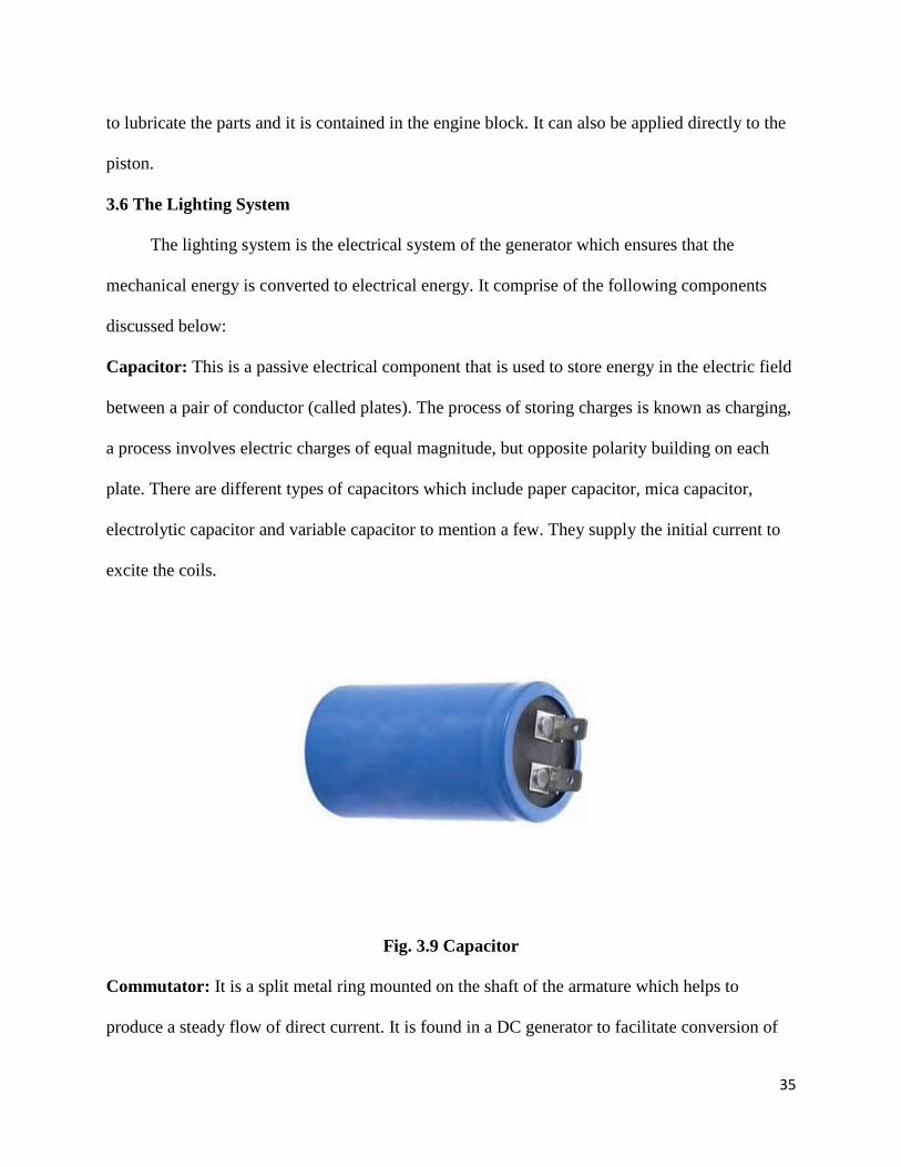
Capacitor: This is a passive electrical component that is used to store energy in the electric field
between a pair of conductor (called plates). The process of storing charges is known as charging,
a process involves electric charges of equal magnitude, but opposite polarity building on each
plate. There are different types of capacitors which include paper capacitor, mica capacitor,
electrolytic capacitor and variable capacitor to mention a few. They supply the initial current to
excite the coils.
Fig. 3.9 Capacitor
Commutator: It is a split metal ring mounted on the shaft of the armature which helps to
produce a steady flow of direct current. It is found in a DC generator to facilitate conversion of
36
alternating current induced in the armature to unidirectional current in the external load circuit
during each revolution. The two halves of the commutator rings are insulated from each other
and serve as the terminals of the armature coil.
Fixed brushes of carbon are held against the commutator as it revolves, connecting the coil
electrically to external wires. As the armature turns, each brush is in contact alternately with the
halves of the commutator, changing position at the moment when the current in the armature coil
reverses its direction. Thus there is a flow of direct current from the generator to the outside
circuit. DC generators are usually operated at fairly low voltages to avoid the sparking between
brushes and commutator that occurs at high voltage.
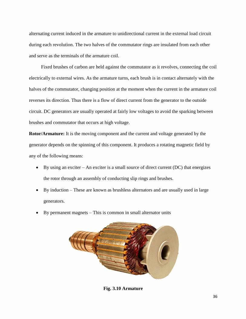
Rotor/Armature: It is the moving component and the current and voltage generated by the
generator depends on the spinning of this component. It produces a rotating magnetic field by
any of the following means:
By using an exciter – An exciter is a small source of direct current (DC) that energizes
the rotor through an assembly of conducting slip rings and brushes.
By induction – These are known as brushless alternators and are usually used in large
generators.
By permanent magnets – This is common in small alternator units
Fig. 3.10 Armature

37
Stator/Field Coil: It is a stationary component which contains a set of electrical conductors
wound in coils over a laminated iron core. It is responsible for creating the magnetic field.
Fig. 3.11 Top view of the field coil
The Alternator: The alternator is responsible for the energy conversion in a generator and
operates on the principle of Faraday‘s law of electromagnetic induction. The law states that
whenever a conductor cuts a magnetic flux, dynamically induce e.m.f is produced in it. This
e.m.f causes current to flow in the conductor circuit if it is closed
Brush: This component is housed in a brush holder and mounted on a spindle. It is needed to
conduct current from the commutator. The amount of current to be conducted from the
commutator determines the number of brushes per spindle. It is usually made of carbon which is
why most people call it carbon brushes. It is mostly found in a brush-free alternator. It is
important to know that the coil of a rotor must be connected to complete the electrical circuit for
proper functioning of the generator. As a result of this, slip rings are affixed to the shaft, and
springs press brushes onto the rings which conduct the current. As the brushes are slowly
abraded, they have to be replaced. An alternator that does not use brushes requires less
maintenance and also produces cleaner power.
38
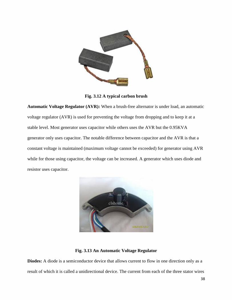
Fig. 3.12 A typical carbon brush
Automatic Voltage Regulator (AVR): When a brush-free alternator is under load, an automatic
voltage regulator (AVR) is used for preventing the voltage from dropping and to keep it at a
stable level. Most generator uses capacitor while others uses the AVR but the 0.95KVA
generator only uses capacitor. The notable difference between capacitor and the AVR is that a
constant voltage is maintained (maximum voltage cannot be exceeded) for generator using AVR
while for those using capacitor, the voltage can be increased. A generator which uses diode and
resistor uses capacitor.
Fig. 3.13 An Automatic Voltage Regulator
Diodes: A diode is a semiconductor device that allows current to flow in one direction only as a
result of which it is called a unidirectional device. The current from each of the three stator wires

39
is only allowed to pass in one direction with a special arrangement of the diodes. This
arrangement is manufactured as a single part and is referred to as the diode pack or diode trio.
Fig. 3.14 Diode
40
CHAPTER 4
GENERATOR FAULTS, TROUBLESHOOTING AND MAINTENANCE
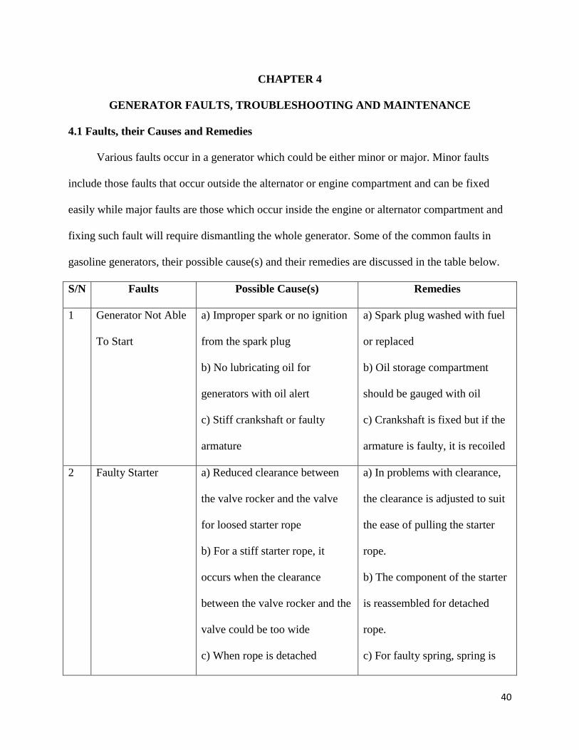
4.1 Faults, their Causes and Remedies
Various faults occur in a generator which could be either minor or major. Minor faults
include those faults that occur outside the alternator or engine compartment and can be fixed
easily while major faults are those which occur inside the engine or alternator compartment and
fixing such fault will require dismantling the whole generator. Some of the common faults in
gasoline generators, their possible cause(s) and their remedies are discussed in the table below.
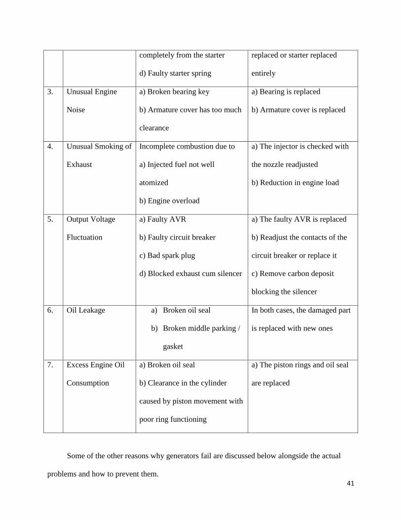
S/N Faults Possible Cause(s) Remedies
1 Generator Not Able
To Start
a) Improper spark or no ignition
from the spark plug
b) No lubricating oil for
generators with oil alert
c) Stiff crankshaft or faulty
armature
a) Spark plug washed with fuel
or replaced
b) Oil storage compartment
should be gauged with oil
c) Crankshaft is fixed but if the
armature is faulty, it is recoiled
2 Faulty Starter a) Reduced clearance between
the valve rocker and the valve
for loosed starter rope
b) For a stiff starter rope, it
occurs when the clearance
between the valve rocker and the
valve could be too wide
c) When rope is detached
a) In problems with clearance,
the clearance is adjusted to suit
the ease of pulling the starter
rope.
b) The component of the starter
is reassembled for detached
rope.
c) For faulty spring, spring is
41
completely from the starter
d) Faulty starter spring
replaced or starter replaced
entirely
3. Unusual Engine
Noise
a) Broken bearing key
b) Armature cover has too much
clearance
a) Bearing is replaced
b) Armature cover is replaced
4. Unusual Smoking of
Exhaust
Incomplete combustion due to
a) Injected fuel not well
atomized
b) Engine overload
a) The injector is checked with
the nozzle readjusted
b) Reduction in engine load
5. Output Voltage
Fluctuation
a) Faulty AVR
b) Faulty circuit breaker
c) Bad spark plug
d) Blocked exhaust cum silencer
a) The faulty AVR is replaced
b) Readjust the contacts of the
circuit breaker or replace it
c) Remove carbon deposit
blocking the silencer
6. Oil Leakage a) Broken oil seal
b) Broken middle parking /
gasket
In both cases, the damaged part
is replaced with new ones
7. Excess Engine Oil
Consumption
a) Broken oil seal
b) Clearance in the cylinder
caused by piston movement with
poor ring functioning
a) The piston rings and oil seal
are replaced
Some of the other reasons why generators fail are discussed below alongside the actual
problems and how to prevent them.

42
Foreign Object Damage:
Problem: Objects can come from external sources or failure of the internal components. They
can pick up energy from the spinning rotor and do extensive damage.
Prevention: Inspect on a regular basis all internal parts that are prone to failure or can be
dislodged. Inspection tests can be a combination of visual inspection along with ultrasonic or
magnetic particle tests on rotating components
Stator Winding Vibration:
Problem: Primarily a design related problem that affects large (>300Mw) generators which have
insufficient end winding bracing to limit the movement of end turns.
Prevention: Proper bracing of the end winding is required to limit motion caused by steady state
and transient electromagnetic forces.
Rotor Winding Distortion:
Problem: Rotor winding distortion caused by poor end turn blocking support design or by
foreshortening of the rotor coils. Foreshortening is caused by thermal forces which compress
rotor coils.
Prevention: Proper design of rotor coils and bracing to support the coils under axial load is
essential. Rotors should be tested for turn to turn shorts at operating speed.
Stator Winding Vibration:
Problem: Primarily a design related problem that affects large (>300Mw) generators which have
insufficient end winding bracing to limit the movement of end turns.
Prevention: Proper bracing of the end winding is required to limit motion caused by steady state
and transient electromagnetic forces.
Overheating:
43
Problem: Overheating of the rotor or stator can lead to insulation failure, shorting of turns and
ground faults. Overheating can result from blocked ventilation passages caused by shifting
insulation components or slot wedges.
Prevention: Inspect on a regular basis to ensure all rotor wedges are "locked" in place
preventing migration and thus blocking of cooling passages.
Contamination:
Problem: For air cooled machines, dirt and dust cause tracking which can lead to electrical
ground faults.
Prevention: Inspect air filters on a regular basis, the filters must be checked and cleaned
regularly. Polarization index (PI) tests give a good indication of overall cleanliness of the rotor
winding.
Rotor Vibration:
Problem: There are many causes, turn-to-turn shorts, rotor coil foreshortening, electrical
grounds, mechanical imbalances, overheating, etc.
Prevention: Comprehensive vibration measuring is effective combined with a regular
maintenance program.
Stator Wedge Looseness:
Problem: When stator wedges become loose, coils can vibrate causing insulation wear leading
to ground faults or turn-to-turn shorts.
Prevention: Inspect on a regular basis tightness of wedge blocks.
Stator Core Damage:
Problem: Stator core looseness can occur over time as pre-tensioned through bolts relax. A
loose core results in insulation wear to coils and laminations resulting in hot spots and core-to-
coil failures.
44
Prevention: Inspect bolt tightness on a regular basis.
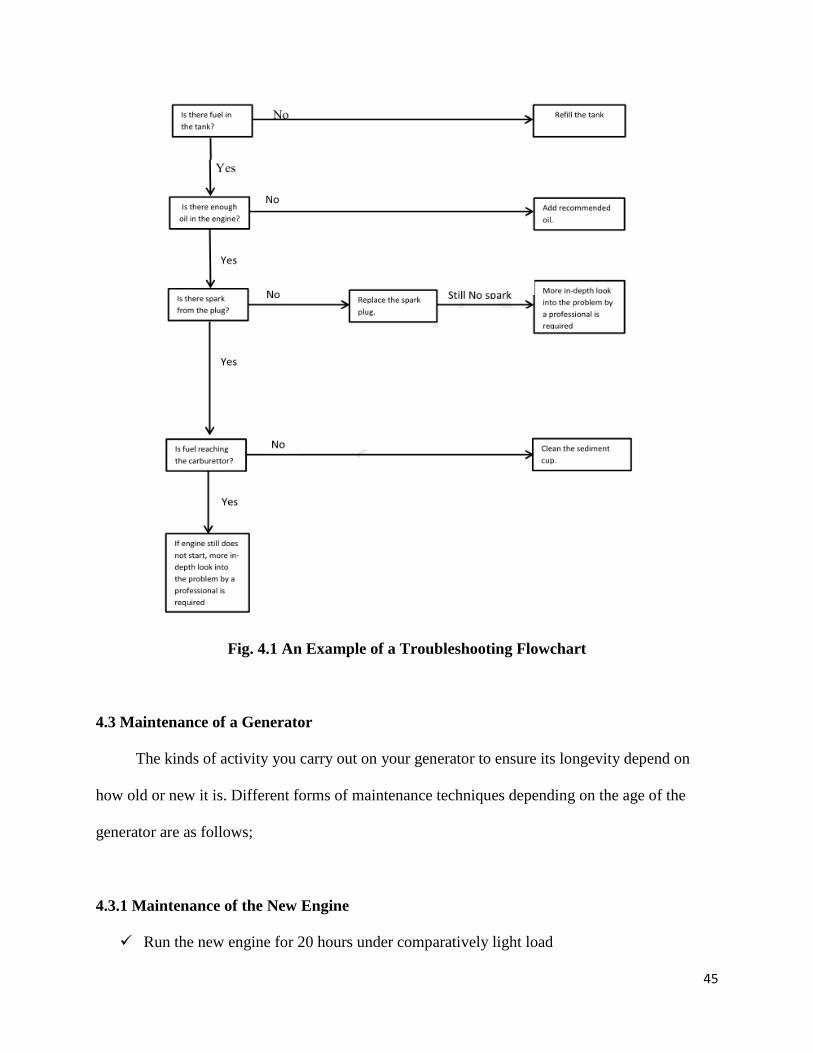
4.2 Troubleshooting
When generators are brought for repair due to one fault or the other, it is necessary to
determine the fault in the generator so as such fault can be fixed. The process or series of steps
taking to ascertain the fault with a system is referred to as troubleshooting. In the case of
generator troubleshooting, it is the various steps taking to find the actual problem responsible for
a generator fault so as to fix and get the generator working properly again.
In order that troubleshooting is done smoothly without anything left aside, it is important
to develop a troubleshooting flowchart for each fault that could occur in a generator so that it
will serve as a guide. Fig 4.1 shows an example of a troubleshooting flow chart for a generator
that refuses to start.
According to the fig. 4.1, one of the steps in troubleshooting a generator which refuses to
start is to find out if the spark plug produces spark or not and the following steps below are
followed:
Remove the spark plug cap and clean any dirt from around the spark plug
Remove the spark plug and install the spark plug in the plug cap.
Set the plug side electrode on the cylinder head.
Crank the engine, sparks should jump across the gap
While the following steps are used to determine if there is proper supply of fuel to the
carburetor:
Turn off the engine switch and loosen the drain screw.
Fuel should flow from the drain when the engine switch is turned on
45
Fig. 4.1 An Example of a Troubleshooting Flowchart
4.3 Maintenance of a Generator
The kinds of activity you carry out on your generator to ensure its longevity depend on
how old or new it is. Different forms of maintenance techniques depending on the age of the
generator are as follows;
4.3.1 Maintenance of the New Engine
Run the new engine for 20 hours under comparatively light load

46
When a new engine or when the engine which has been spared from service for some
time is put into service, better renew the lubricating oil after 40hours of operation. Do it
again after another 60 hours and then once every 100 hours
4.3.2 Every 8 Hours of Operation
After 8 hours of continuous running, stop the engine and check the lubricating oil level. If
it falls below the lower marked line on the dipstick, replenish clean oil
Check for leakage and make sure all leakages are corrected
Clean the dust gathered on the openings and the passages between the cooling fins
Make sure to keep the outline of the engine clean
Remove the cylinder head cover, fill a little bit of engine oil into the orifice on the intake
and exhaust rocker arms
4.3.3 Every 100 Hours of Operation
Clean the fuel screen of the fuel tank
Wipe off dust gathered on the air filter paper cartridge with a soft brush. Renew the filter
cartridge if it is chocked or damaged
Dismount the screen from the air cleaner and wash it in clean fuel.
Clean the crankcase and renew the lubricating oil
Check and adjust the valve clearance
Check the tightness of bolts
4.3.4 Every 500 Hours of Operation
Wash up the fuel tank and fuel cock
Clean up the exhaust pipe and silencer
Clean the fuel filter element with fuel or kerosene. Renew if damaged
Wash the crankcase with clean fuel

47
Clean the nozzle
Check the valve for tightness
Adjust the valve clearance if necessary
Check the piston ring
Renew the air filter paper cartridge

48
CHAPTER 5
TOOLS USED AND SAFETY RULES OBSERVED IN GENERATORS WORKSHOPS
5.1 Tools Used In Generators Workshops
There are so many tools used in the workshop for the assembling and disassembling, as
well as repair of generators. These workshop tools should always be handled with care to prevent
workshop hazards and damage to the tools and generator. Some of the safety rules I observed to
ensure careful handling of tools during the SWEP program are as follows:
The tools (e.g. the sledge hammer) were handled with care when in use to avoid damage
and ineffectiveness.
The tools were cleaned after use and kept in the tool box for easy access whenever the
need for use of such tool arises.
I always used the right tool for each job. For example, I used a star screw driver and not a
flat screw driver for driving star nuts into the appropriate place.
I never tried to catch a falling tool.
I never used tools when I was fatigued. This should be so for other things like alcohol or
medication.
The various tools used in the repair and maintenance of a generator include;
Spanners: The standard name for spanner is wrench and it is a tool with which mechanical
advantage and grip is provided while applying torque to turn objects such as bolts and nuts. It is
also used at times to keep them from rotating. It is the most commonly used tool in a generator
repair and maintenance workshop. Most quality spanners are made from an alloy of chromium
and vanadium and are drop-forged. They could be chrome-plated to resist rusting and enhance
ease cleaning. They come in different forms and sizes and are as follows:
49
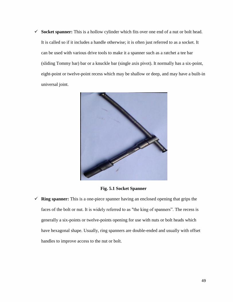
Socket spanner: This is a hollow cylinder which fits over one end of a nut or bolt head.
It is called so if it includes a handle otherwise; it is often just referred to as a socket. It
can be used with various drive tools to make it a spanner such as a ratchet a tee bar
(sliding Tommy bar) bar or a knuckle bar (single axis pivot). It normally has a six-point,
eight-point or twelve-point recess which may be shallow or deep, and may have a built-in
universal joint.
Fig. 5.1 Socket Spanner
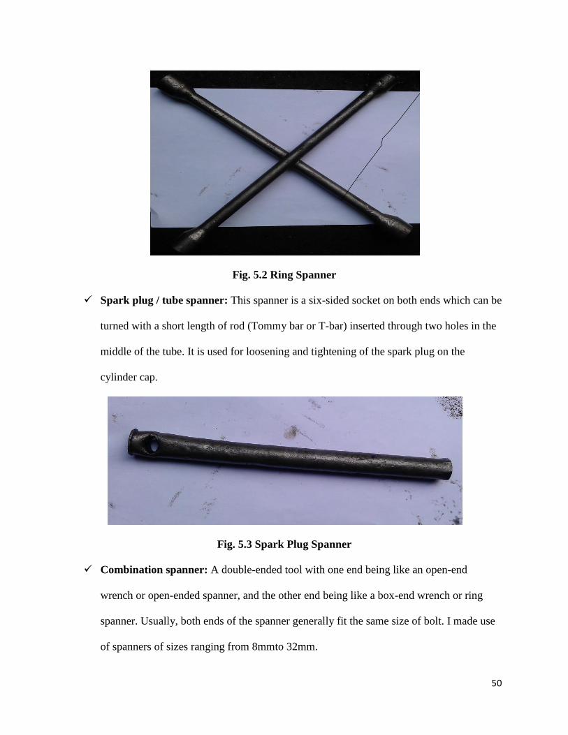
Ring spanner: This is a one-piece spanner having an enclosed opening that grips the
faces of the bolt or nut. It is widely referred to as "the king of spanners”. The recess is
generally a six-points or twelve-points opening for use with nuts or bolt heads which
have hexagonal shape. Usually, ring spanners are double-ended and usually with offset
handles to improve access to the nut or bolt.
50
Fig. 5.2 Ring Spanner
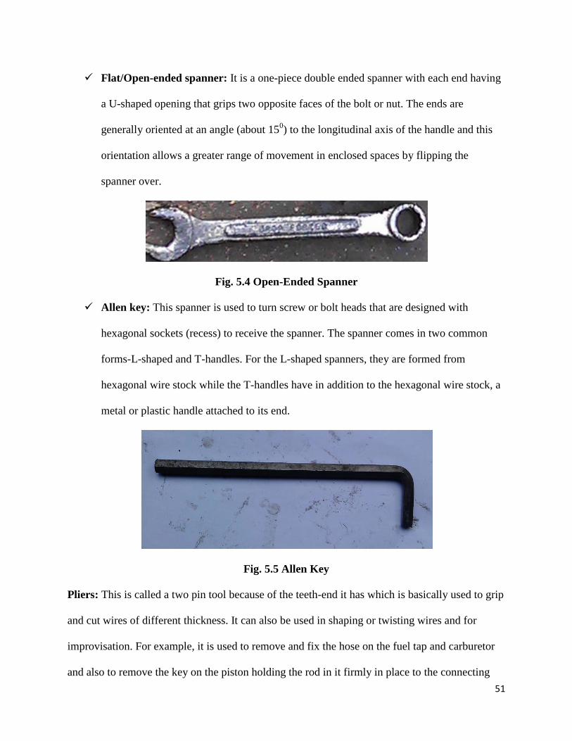
Spark plug / tube spanner: This spanner is a six-sided socket on both ends which can be
turned with a short length of rod (Tommy bar or T-bar) inserted through two holes in the
middle of the tube. It is used for loosening and tightening of the spark plug on the
cylinder cap.
Fig. 5.3 Spark Plug Spanner
Combination spanner: A double-ended tool with one end being like an open-end
wrench or open-ended spanner, and the other end being like a box-end wrench or ring
spanner. Usually, both ends of the spanner generally fit the same size of bolt. I made use
of spanners of sizes ranging from 8mmto 32mm.
51
Flat/Open-ended spanner: It is a one-piece double ended spanner with each end having
a U-shaped opening that grips two opposite faces of the bolt or nut. The ends are
generally oriented at an angle (about 150) to the longitudinal axis of the handle and this
orientation allows a greater range of movement in enclosed spaces by flipping the
spanner over.
Fig. 5.4 Open-Ended Spanner
Allen key: This spanner is used to turn screw or bolt heads that are designed with
hexagonal sockets (recess) to receive the spanner. The spanner comes in two common
forms-L-shaped and T-handles. For the L-shaped spanners, they are formed from
hexagonal wire stock while the T-handles have in addition to the hexagonal wire stock, a
metal or plastic handle attached to its end.
Fig. 5.5 Allen Key
Pliers: This is called a two pin tool because of the teeth-end it has which is basically used to grip
and cut wires of different thickness. It can also be used in shaping or twisting wires and for
improvisation. For example, it is used to remove and fix the hose on the fuel tap and carburetor
and also to remove the key on the piston holding the rod in it firmly in place to the connecting

52
rod while servicing a 0.95KVA generator. A typical pliers have a pair of handles, the pivot (often
formed by a rivet), and the head section with the gripping jaws or cutting edges forming the three
elements.
Fig. 5.6 Plier
File: This is mainly used to remove the carbon deposits from piston grooves and other suitable
generator parts. It is produced from hardened carbon steel with a soft tang to which the handle
can be fixed.
Fig. 5.7 Rectangular File

53
When a file has a single series of teeth cut across its face, it is known as single-cut file and
with two sets of teeth cut across its face, and it is known as double-cut. The different kinds of
files used are half-rounded, file square file, round file, and triangle file which is based on nature
of the job at hand.
Screwdriver: This is a device that is specifically designed for inserting, tightening, loosening
and removing screws. The screw driver is at times used to remove carbon from a hole like the
grooves in the engine block. A typical hand screwdriver comprises an approximately cylindrical
handle of a size and shape held by a human hand and an axial shaft fixed to the handle. The tip is
shaped to fit a particular type of screw. The handle and shaft allow the screwdriver to be
positioned and supported and when rotated to apply torque or moment. It may be in form of
testers or just the ordinary.
Fig. 5.8 Screw Driver (Flat and Star)
Hammer: This is the tool used when one intends to deliver an impact on an object. It is used for
fitting parts and breaking up objects and can also be used in straightening or beating metal sheets
into plain form. Its usual features are a handle and a head with most of the weight in the head.
There are different types of hammers used in the generator workshop but the common ones are
the ball-peen hammer and sledge hammer.

54
Fig. 5.9 Hammer
Soldering Iron: This is used to solder disjoined pieces of wire. It is normally electrically
powered. When the soldering tip is very hot, it is used to melt the lead placed between the
surfaces to be soldered.
Fig. 5.10 Soldering Iron
Multimeter: This tool is an electronic measuring instrument used to measure the output current
and voltage from the generator. It is also called Avometer and is of two forms – digial and
analog multimeter. A standard multimeter may include features such as the ability to measure

55
voltage, current and resistance. They are capable of measuring the capacitance, inductance and
temperature of an object.
Fig. 5.11 A Digital Multimeter
5.2 Safety Rules Observed In Generators Workshops
One of the fundamental principles every engineer and technician should have at the back
of their mind when working is the fact that safety is first. This is very important in order to avoid
workshop hazards that could result in the loss of lives and property. As a result of this, I will be
listing some of the safety rules which must be adhered to while working in a generator
workshop.
No smoking, flames or sparks should be allowed in a generator workshop as this could
lead to outbreak of fire since fuels like petrol are usually contained an used in the
workshop.

56
Proper protective clothings ( both shoe and overall) should be worn at all times in the
workshop
Avoid touching the silencer when it is still hot especially while the engine is still running.
Ensure that flammable materials are kept away from generator workshops
Any fuel spilled should be wiped off before starting the engine because fuel vapour is
extremely flammable and may ignite after the engine has started.
There must be no horseplay in the workshop as it is a working environment
57
CHAPTER 6
PRACTICAL SKILLS LEARNT DURING SWEP
During the course of the SWEP program, I learnt a lot of practical skills which I will be
sharing in this chapter of my report. The most important practical skill learnt was the servicing of
gasoline generator of various sizes. The servicing of generators and many other skills learnt are
discussed as follows:
6.1 Servicing of Gasoline Generator
Servicing of a generator is deemed necessary when the generator’s efficiency reduces.
Servicing basically involves renewal and maintenance of a machine or its components. This
becomes so obvious when a generator fails to start, produces its low power output and so on. It
requires dismantling the components.
The following signs suggest that a generator needs servicing;
Excessive smoke emission
Unusual sounds from the generator
Voluntary stoppage of the generator after working for awhile
Majority of the jobs we handle daily in my place of placement are generator servicing. In every
10 jobs handled, servicing could be as much as 5. For medium and large gasoline generators,
servicing is deemed very easy and simple as it involves the changing of the lubricating oil,
checking of the spark plug and parts cleaning. But for the 0.95KVA generator, it involves a little
more work. The various steps taking during servicing is explained below:
Medium and Large Generators:
a) Open the oil storage compartment and empty the condemned oil in the compartment
b) Refill the compartment with a good product of fresh oil (e.g. Con-Oil) and gauge it
before closing the compartment.

58
c) Loosen the spark plug with the spark plug key and check if dirty or damaged.
d) Clean the spark plug if dirty or replace with new one if damaged. Make sure the spark
plug is tightened back using the spark plug key
e) Use fuel to clean the generator body parts.
Small (0.95KVA) Generator:
a) Loosen the bolt nuts to remove the fuel tank after detaching the fuel hose from the tap.
b) Loosen the exhaust silencer
c) Loosen the starter to have easy access to the cylinder block
d) The cylinder cap is removed as well as the cylinder block to get access to the piston
Fig. 6.1 Loosening Bolts to Remove Cylinder Cap
e) The piston is then removed by removing the keys at both ends to allow the removal of the
piston
f) The piston rings are removed and washed with fuel to remove carbon deposits. The
piston is also washed with fuel to remove the carbon content.
59
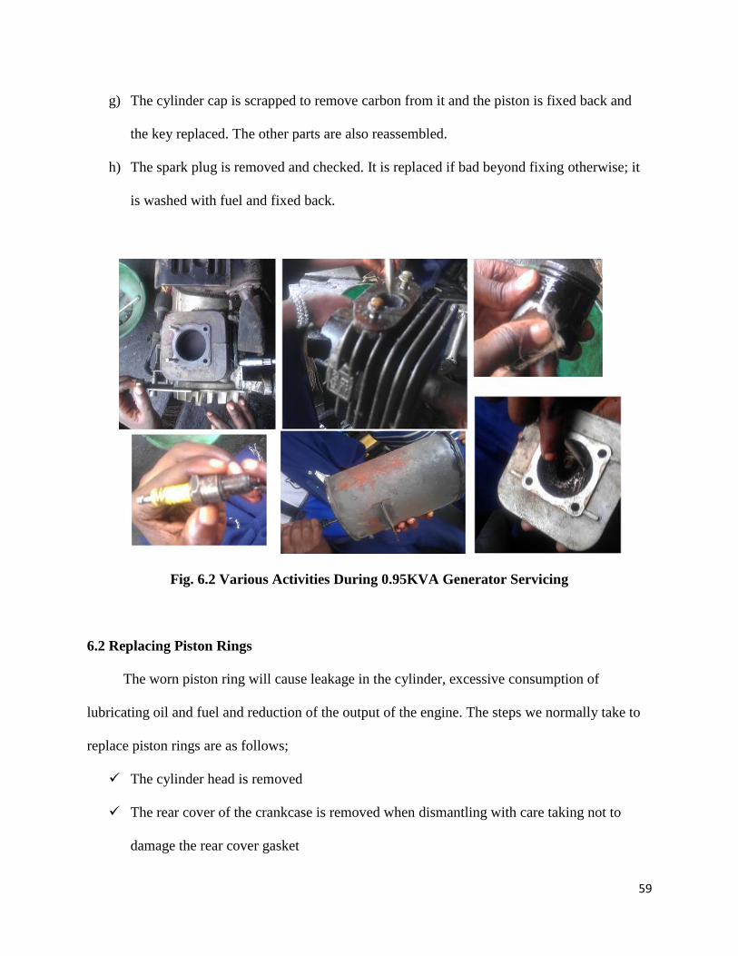
g) The cylinder cap is scrapped to remove carbon from it and the piston is fixed back and
the key replaced. The other parts are also reassembled.
h) The spark plug is removed and checked. It is replaced if bad beyond fixing otherwise; it
is washed with fuel and fixed back.
Fig. 6.2 Various Activities During 0.95KVA Generator Servicing
6.2 Replacing Piston Rings
The worn piston ring will cause leakage in the cylinder, excessive consumption of
lubricating oil and fuel and reduction of the output of the engine. The steps we normally take to
replace piston rings are as follows;
The cylinder head is removed
The rear cover of the crankcase is removed when dismantling with care taking not to
damage the rear cover gasket

60
The connecting rod nuts are then unscrewed and the connecting rod cap taken off
The piston connecting rod assembly is pushed out of the cylinder bore from the cylinder
head side
The piston rings are dismantled by means of a piston ring expander
After dismantling, the piston rings are soaked in fuel and de-carbonized with a chip or
brush
The carbon deposits on the piston surface and ring grooves are scraped off with a chip
and then piston is cleaned in fuel
The upper part of the cylinder is de-carbonized as well
The piston ring gap is checked to see if it is over 1mm by placing the ring into the
cylinder liner about 20mm. If the gap is over 1mm, the ring is replaced.
The piston connecting rod assembling and smear is cleaned with little clean oil before
installing into the cylinder. All the piston rings are then compressed in a guide tool and
placed on top of the liner before the assembling is tapped lightly into the cylinder liner
with a wooden handle
The oil hole of the connecting rod small end is set upwards and the piston ring is
positioned
Finally, the connecting rod cap is reinstalled, and the connecting rod bolts is tightened.
6.3 Adjustment of Valve Clearance
Without proper adjustment of valve clearance, the engine of a generator is likely not going
to start. So the intake and exhaust valve is normally adjusted to 0.1-0.2mm following the
following steps below;
The cylinder head cover is removed
61
The flywheel is turned until the “O” mark on its periphery lines with “Timing Mark” on
the air cowling
The set nut is slackened with a wrench and the adjusting screw is turned on the rooker
arm with the screw driver
The valve clearance is then adjusted to 0.1 -0.2mm with the help of a feeler gauge
After the adjustment, the adjusting screw is held with drive while the set nut is tightened.
The valve clearance is then checked once again by means of a feeler gauge. If okay, the
cylinder head cover is assembled.
6.4 Air Cleaner Service
This is another common generator problem that I learnt to fix during the SWEP program.
When the air cleaner of a generator is dirty, it will restrict air flow to the carburetor. In order to
prevent carburetor malfunction, the air cleaner should be serviced more frequently. If the engine
is used in extremely dusty areas, it is advised that the air cleaner should be serviced regularly. At
the company, petrol is usually used to clean the filter element which is risky as it can cause fire
or explosion. To prevent this, the element is thoroughly dried. Soapy water or a non-flammable
solvent is recommended.
Steps taking to service the air cleaner are as follows;
The air cleaner is unsnapped from the air cleaner cover clips and the cover is removed.
Thereafter, the element is removed.
The element is washed in petrol and allowed to dry thoroughly.
The element is soaked in clean engine oil and excess oil is squeezed out. If too much is
left in the element, the engine will smoke during initial start-up.
The element is restored and the cover is reinstalled.

62
6.5 Fuel Sediment Cup Cleaning
For the carburetor to function properly, dirt and water which may be in the fuel tank needs
to be prevented from entering the carburetor. The fuel sediment cup performs this function and
that is why the sediment cup needs to be cleaned if the generator engine has not be run for a long
time.
Steps taking to do this are as follows;
The fuel lever is turned to the OFF position. The Sediment cup, O – ring and filter are
removed.
The sediment cup, O-ring, and filter are cleaned in petrol. Any non-flammable or high
flash point solvent will also do.
The filter, O – ring, and sediment cup are reinstalled.
The fuel valve is turned ON and checked for leaks.

63
CONCLUSION AND RECOMMENDATION
Conclusion
The Students’ Work Experience Program has helped me to apply my theoretical
knowledge to real practical situations. It opened my eyes to the various expectations from the
engineer by the society. I also learnt some of the challenges facing the profession and from
experience, learnt that safety is key in the profession.
The eight weeks duration spent at God’s Wisdom Technical Works has provided me the
opportunity to master practical skills in servicing the petrol engine generator, especially the
0.95KVA generator; as well as assembling and disassembling of internal combustion engine and
alternator. I also acquired practical skills in troubleshooting and fixing of faults in petrol engine
generators.
I would rate my experience at God‘s Wisdom Technical Works as worthwhile even though
there seems to be little relationship between my experience during the industrial training and
class work.
Finally, I must congratulate my fellow colleagues and myself zealously participating in
this program. The skills and experience gathered during the course of this training cannot be
overemphasized.
Recommendation
My recommendation is that renowned industries should be chosen for the industrial
training as this will enhance a better learning and ensure a secured environment for the students.
Also, the length of time of the training is rather short, if it can be elongated, the quantity and
quality of experience gained would be augmented.
Finally, ITCC should more flexible in the placement of students in industries so that
students will learn what truly interests them.

64
References
1. www.wikipedia.org/
2. www.edisontechcenter.org/
3. www.images.googles.com.ng
4. A Textbook of Electrical Technology by B.L. Theraja and A.K. Theraja
5. Generator and Exciter Basics by Whitby Hydro Energy Services Corporation
6. Electrical and Electronics Technology by Hughes


![Software User Manual - ESAswe.ssa.esa.int/DOCS/SSA-DC/SSA-SWE-SWEP-SUM-0001.pdf[AD.29] SWE Portal Services – Software Requirements Specification SSA-SWE-SWEP-SRS-0200 [AD.30] File](https://img.pdfslide.us/doc/110x75/5f8dbc6dab6efb5e327aa85e/software-user-manual-ad29-swe-portal-services-a-software-requirements-specification.jpg)