Embed Size (px)
Citation preview

INTERRUPTS OF MICROPROCESSOR
8085

CONTENTS
Sr no contents
1 Introduction
2 classification of interrupts
3 Hardware interrupt
4 SIM Instruction
5 RIM instruction
6 Block diagram of Hardware
interrupt
7 Software interrupt

what is Interrupt?
Interrupt is a mechanism by which an I/O or an instruction can
suspend the normal execution of processor and get itself serviced.
Generally, a particular task is assigned to that interrupt signal. In the
microprocessor based system the interrupts are used for data transfer
between the peripheral devices and the microprocessor.
INTRODUCTION

After receiving an interrupt signal from the peripheral, the
microprocessor executes current instruction completely.
Store the contents of program counter i.e. return address on the stack
and then executes interrupts service (ISR) to provide service to the
interrupting device.
After servicing the device, the microprocessor transfer program
control back to the program where interrupt occurs by reloading the
content of program counter which has been stored on the stack when
an interrupt occurs.

Main program
XY
µp is interrupt
ISR
RET
HLT
EXAMPLE:-
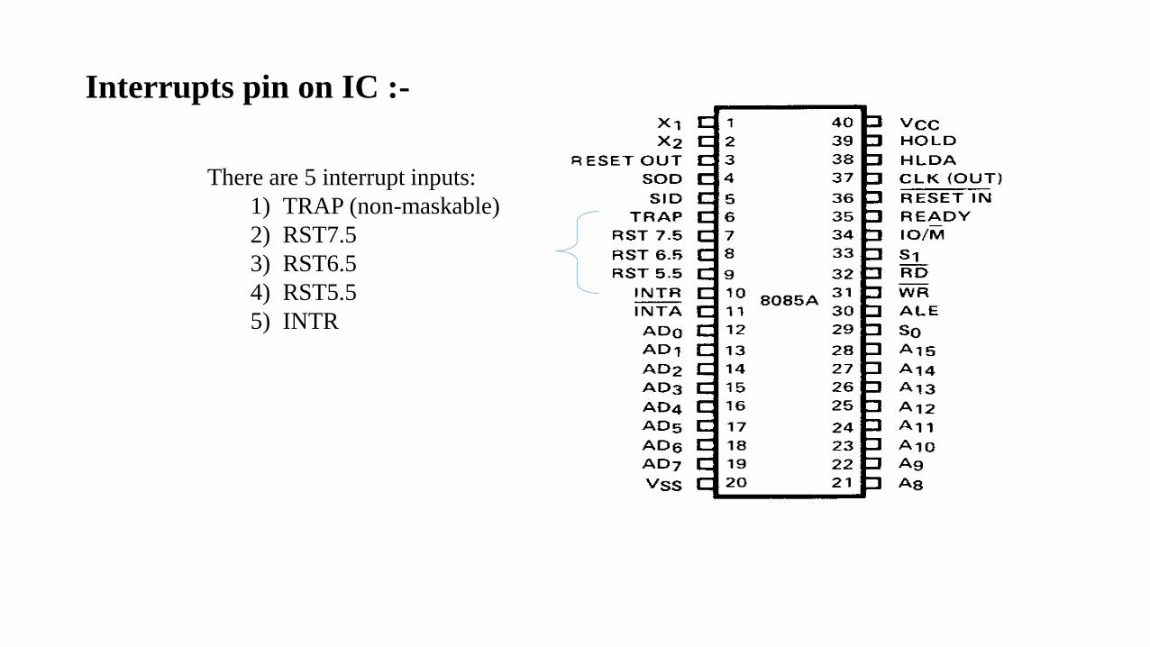
There are 5 interrupt inputs:
1) TRAP (non-maskable)
2) RST7.5
3) RST6.5
4) RST5.5
5) INTR
Interrupts pin on IC :-

CLASSIFICATION OF INTERRUPTS
Interrupts
Hardware Software
Maskable• RST 7.5
• RST 6.5
• RST 5.5
• INTR
Non-maskeble• TRAP
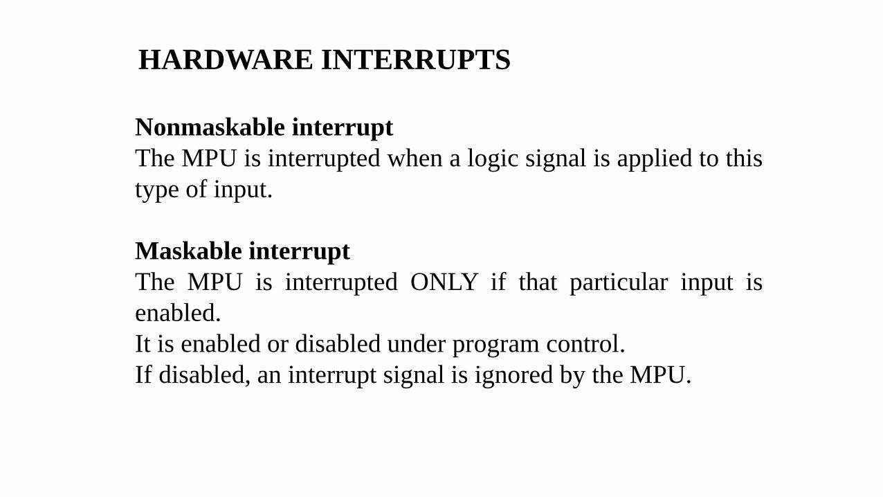
Nonmaskable interrupt
The MPU is interrupted when a logic signal is applied to this
type of input.
Maskable interrupt
The MPU is interrupted ONLY if that particular input is
enabled.
It is enabled or disabled under program control.
If disabled, an interrupt signal is ignored by the MPU.
HARDWARE INTERRUPTS

RESPONDING TO INTERRUPTS
• Responding to an interrupt may beimmediate or delayed depending onwhether the interrupt is maskable or non-maskable and whether interrupts are beingmasked or not.
• There are two ways of redirecting theexecution to the ISR depending onwhether the interrupt is vectored or non-vectored.• Vectored: The address of the subroutine is
already known to the Microprocessor• Non Vectored: The device will have to supply
the address of the subroutine to theMicroprocessor
Interrupt name Maskable Vectored
INTR Yes No
RST 5.5 Yes Yes
RST 6.5 Yes Yes
RST 7.5 Yes Yes
TRAP No Yes

Representation of maskable and non-maskable interrupts

Non-maskable interrupt :Can not be delayed or Rejected. It’s types as
follows.
TARP: a non mask able interrupt known as NMI, it has the highest priority,
it can not be enabled ; and it cannot be disable. It is edge and level triggered.
This means hat the TRAP must go high and remain high until it is
acknowledged.
Maskable interrupt : Can be delayed or Rejected and Enable Or
Disable By EI And DI Instruction. It’s types as follows.
RST 7.5: The RST 7.5 interrupt is a maskable interrupt. It has the second highest
priority. It is edge sensitive. ie. Input goes to high and no need to maintain high
state until it recognized. Enabled by EI instruction. It is disabled by,
1.DI instruction
2.System or processor reset.
3.After reorganization of interrupt.

RST 6.5 and 5.5: The RST 6.5 and RST 5.5 both are level triggered. ie. Input
goes to high and stay high until it recognized. Maskable interrupt. Enabled by EI
instruction. It is disabled by,
1.DI, SIM instruction
2.System or processor reset.
3.After reorganization of interrupt.
The RST 6.5 has the third priority whereas RST 5.5 has the fourth priority.
INTR: INTR is a maskable interrupt. Enabled by EI instruction. It is disabled by,
1.DI, SIM instruction
2.System or processor reset.
3.After reorganization of interrupt.
It is Non- vectored interrupt. After receiving INTA (active low) signal, it has to
supply the address of ISR. It has lowest priority. It is a level sensitive interrupts. i.e.
Input goes to high and it is necessary to maintain high state until it recognized.
After receive this interrupt µp response with INTA pulse and it’s interrupt address is
given by external circuit.
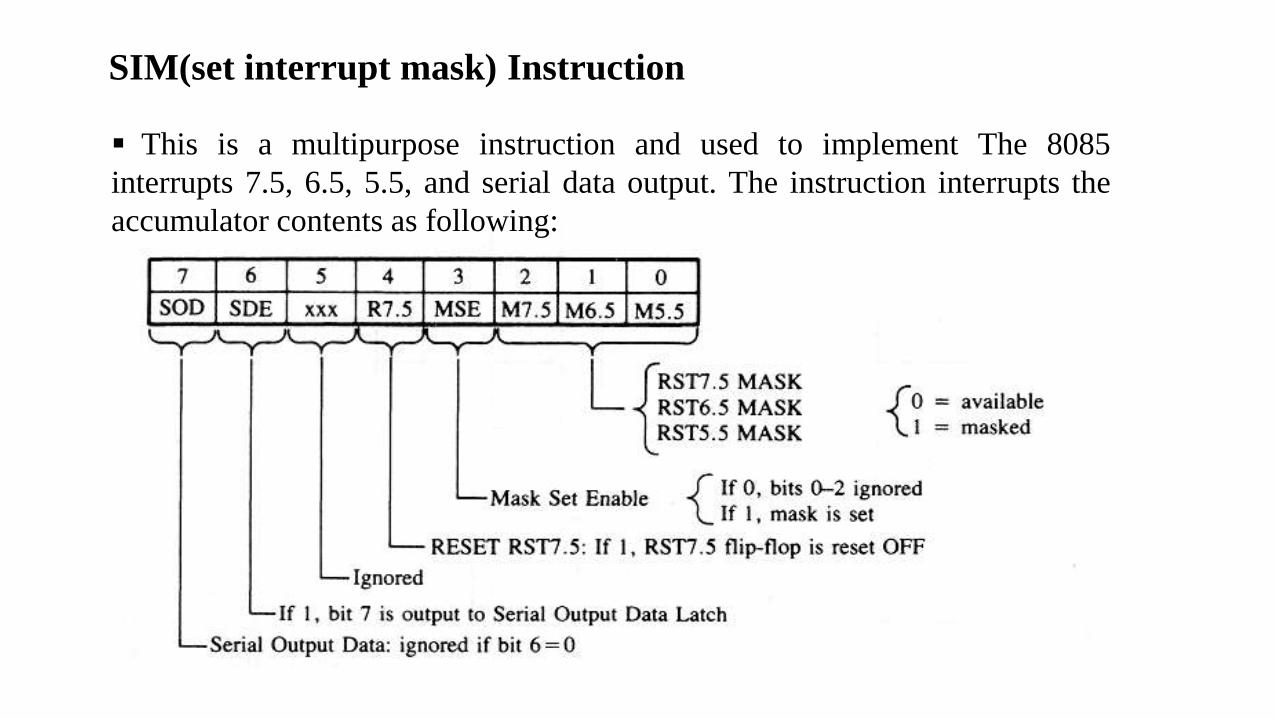
SIM(set interrupt mask) Instruction
This is a multipurpose instruction and used to implement The 8085
interrupts 7.5, 6.5, 5.5, and serial data output. The instruction interrupts the
accumulator contents as following:
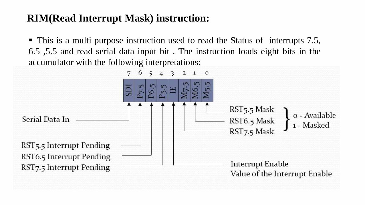
RIM(Read Interrupt Mask) instruction:
This is a multi purpose instruction used to read the Status of interrupts 7.5,
6.5 ,5.5 and read serial data input bit . The instruction loads eight bits in the
accumulator with the following interpretations:
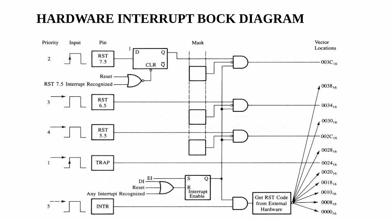
HARDWARE INTERRUPT BOCK DIAGRAM

SOFTWARE INTERRUPT
The software interrupts are program instructions. These
instructions are inserted at desired locations in a program. The
8085 has eight software interrupts from RST 0 to RST 7. When
microprocessor is interrupt by giving instruction in the main
program. The it is called as software interrupt.
They allow the microprocessor to transfer program control from the main
program to the subroutine program. After completing the subroutine program,
the program control returns back to the main program.
We can calculate the vector address of these interrupts using the formula
given below: Vector Address = Interrupt Number * 8
For Example:
RST2: vector address=2*8 = 16
RST1: vector address=1*8 = 08
RST3: vector address=3*8 = 24

Restart Instruction Equivalent to
RST0 CALL 0000H
RST1 CALL 0008H
RST2 CALL 0010H
RST3 CALL 0018H
RST4 CALL 0020H
RST5 CALL 0028H
RST6 CALL 0030H
RST7 CALL 0038H
TABLE OF SOFTWARE INTERRUPT

X
RST 1
Y
---
---
.
.
.
---
RET
EXAMPLE:-
Main program
ISR
6107H
6108H
6109H
0008H
0009H
2501H
2502H

Thank you