Embed Size (px)
Citation preview

DIFFERENT TYPES OF HYDRAULIC
ACCUMULATORS & DAMPENERS
Author
Prem Baboo
Sr. Manager (Prod)
National Fertilizers Ltd. India
F.I.E., Institution of Engineers (India)
Technical Advisor & an Expert for www.ureaknowhow.com
What's an accumulator?
A hydraulic accumulator is a device in which potential energy is stored in
the form of a compressed gas or spring, or by a raised weight to be used to
exert a force against a relatively incompressible fluid or the pressure
storage reservoir in which a non-compressible hydraulic fluid is under
pressure by an external force.
How Accumulators Work
Accumulators operate by making use of the considerable difference in
compressibility between a gas and fluid. Using the bladder design, the
nitrogen in the bladder is highly compressible while the hydraulic oil in the
fluid side of the shell is virtually non-compressible. The bladder contained
in the shell is pre-charged with nitrogen gas to a pressure calculation
determined by system parameters and the work to be done. After being
pre-charged, the bladder occupies almost the whole volume of the shell.
From there, the operation of an accumulator can be broken down into three
basic stages:
(a) When the hydraulic pump in the system is turned on it causes
fluid to enter the accumulator. When fluid fills the shell,
accumulator charging begins as the nitrogen in the bladder is

compressed by a fluid pressure greater than its pre-charge
pressure. This is the source of stored energy.
(b) As the bladder compresses due to the fluid filling the shell, it
"deforms" in shape, taking up less space in the shell while at the
same time, pressure in the bladder increases. This bladder
"deformation" ceases when the pressure of the system fluid and
the now compressed nitrogen become balanced.
(c) Upon downstream system demand, fluid system pressure falls and
the stored fluid is pushed out of the accumulator shell and
returned to the system under pressure exerted by the compressed
nitrogen, whose pressure is now greater than the fluid pressure.
Upon completion of whatever hydraulic system function the
accumulator was designed to do, the cycle starts all over again
with step one.
One of the most important considerations in applying accumulators is
calculating the correct pre-charge pressure for the type of accumulator
being used, the work to be done and system operating parameters. Pre-
charge pressure is generally 80 - 90% of the minimum system working
pressure to allow a small amount of fluid to remain in the accumulator.
This prevents the bladder, diaphragm or piston from striking the opposite
end of the pressure vessel, getting fouled up in discharge valuing or
blocking fluid passages. Too high or too low of a pre-charge pressure can
cause accumulator damage or failure.
The accumulators use nitrogen to keep the hydraulic fluid pressurized.
When the fluid is pumped into an accumulator the nitrogen (N2) inside the
accumulator is compressed. When all the hydraulic fluid is in an
accumulator designed for high pressure side, the pressure of the nitrogen
reaches 340 bars. If empty of fluid, the pressure of the nitrogen is about
140 bars. The pressure of the nitrogen in the low pressure reservoir will
vary from 4.0 bar when empty to 14.0 bar when full. They are used in fluid
power systems to accumulate energy and to smooth out pulsations. A
hydraulic system utilizing an accumulator can use a smaller fluid pump
since the accumulator stores energy from the pump during low demand
periods. This energy is available for instantaneous use, released upon
demand at a rate many times greater than could be supplied by the pump
alone. Accumulators can also act as surge or pulsation absorbers, much as
an air dome is used on pulsating piston or rotary pumps. They will cushion
hydraulic hammer, reducing shocks caused by rapid operation or sudden
starting and stopping of power cylinders in a hydraulic circuit.

Where are accumulators used?
Accumulators can be applied creatively in any number of situations,
including:
Emergency and safety:
An accumulator which is kept constantly under pressure is valuable in the
event of an electrical power failure as it can provide flow and pressure to
perform an additional function or complete a machine cycle.
Knock or pulsation dampening:
An accumulator can be used to cushion the pressure spike from sudden
valve closure, the pulsation from pumps or the load reaction from sudden
movement of parts connected to hydraulic cylinders.
Leakage compensation:
An accumulator can be used to maintain pressure and make-up for lost
fluid due to internal leakage of system components including cylinders and
valves.
Thermal expansion:
An accumulator can absorb the pressure differences caused by
temperature variations in a closed hydraulic system.
Energy conservation:
An accumulator can be used to supplement a pump during peak demand
thereby reducing the size of the pump and motor required. The
accumulator is charged during low demand portions of the pump cycle
time and then discharges during the high demand portions of the system.
Noise reduction:
An accumulator is effective at reducing hydraulic system noise caused by
relief valves, pump pulsations, system shock and other circuit generated
noises.
Improved response times: An accumulator (bladder type) has virtually

instantaneous response time that can provide fluid very quickly to fast-
acting valves such as servos and proportional to improve their
effectiveness.
FUNCTIONS.
Accumulators can provide several functions, such as
1. Store Energy
Hydro-pneumatic accumulators incorporate a gas in conjunction with a
hydraulic fluid. The fluid has little dynamic power storage qualities. The
fluid normally used in fluid power applications can be reduced in
volume only about 1.7% under a pressure of 345 bar. Therefore when
only 2% of the total contained volume is released, the pressure of the
remaining oil in the system will drop to zero. However, the relative
incompressibility of a hydraulic fluid makes it ideal for fluid power
systems and provides quick response to power demand. The gas, on the
other hand, a partner to the hydraulic fluid in the accumulator, can be
compressed to high pressures and low volumes. Potential energy is
stored in this compressed gas to be released upon demand. This energy
can be compared to that of a raised pile driver ready to transfer its
tremendous energy upon the pile. In the piston type accumulator the
energy in the compressed gas exerts pressure against the piston
separating the gas and hydraulic fluid. The piston in turn forces the fluid
from the cylinder into the system and to the location where useful work
will be accomplished
2. Absorbs Pulsation
In most fluid power applications, pumps are used to generate the
required power to be used or stored in a hydraulic system. Many pumps
deliver this power in a pulsating flow. The piston pump, as commonly
used for higher pressures, tends to produce pulsation detrimental to a
high pressure system. An accumulator properly located in the system
will substantially cushion these pressure variations.
3. Cushions Operating Shock
In many fluid power applications the driven member of the hydraulic
system stops suddenly, creating a pressure wave which is sent back
through the system. This shock wave can develop peak pressures
several times greater than normal working pressures and can be the
source of system failure or objectionable noise. The gas cushion in an
accumulator, properly placed in the system, will minimize this shock.
An example of this application is the absorption of shock caused by
suddenly stopping the loading bucket on a hydraulic front end loader.
Without an accumulator, the bucket, weighing over 2 tons, can
completely lift the rear wheels of a loader off the ground. The severe
shock to the tractor frame and axle, as well as operator wear and
tear, is overcome by the addition of an adequate accumulator to the
hydraulic system.
4. Supplements Pump Delivery.
An accumulator, capable of storing power, can supplement the fluid
pump in delivering power to the system. The pump stores potential
energy in the accumulator during idle periods of the work cycle. The
accumulator transfers this reserve power back to the system when
the cycle requires emergency or peak power. This enables a system
to utilize a much smaller pump, resulting in savings in cost and
power.
5. Maintains Pressure
Pressure changes occur in a hydraulic system when the liquid is
subjected to rising or falling temperatures. Also, there may be
pressure drop due to leakage of hydraulic fluid. An accumulator
compensates for such pressure changes by delivering or receiving a
small amount of hydraulic liquid. In the event the main power source
should fail or be stopped, the accumulator would act as an auxiliary
power source, maintaining pressure in the system.
6. Dispenses.
An accumulator may be used to dispense fluids under pressure, such
as lubricating greases and oils.
DIFFERENT TYPE OF HYDRAULIC ACCUMULATOR
Accumulators basically comprise of two compartments: one of the
compartments is filled with gas; the other compartment, which is
connected to the hydraulic circuit, is filled with fluid. The accumulator shell
is made of carbon steel, stainless steel or aluminium. Depending on
separating elements, we can distinguish following types of hydraulic
accumulators:
1. Bladder accumulators
2. Direct Contact type Gas filled Accumulator
3. Diaphragm accumulators
4. Piston accumulators
5. Metal Bellow Accumulator.
6. Spring type Accumulator
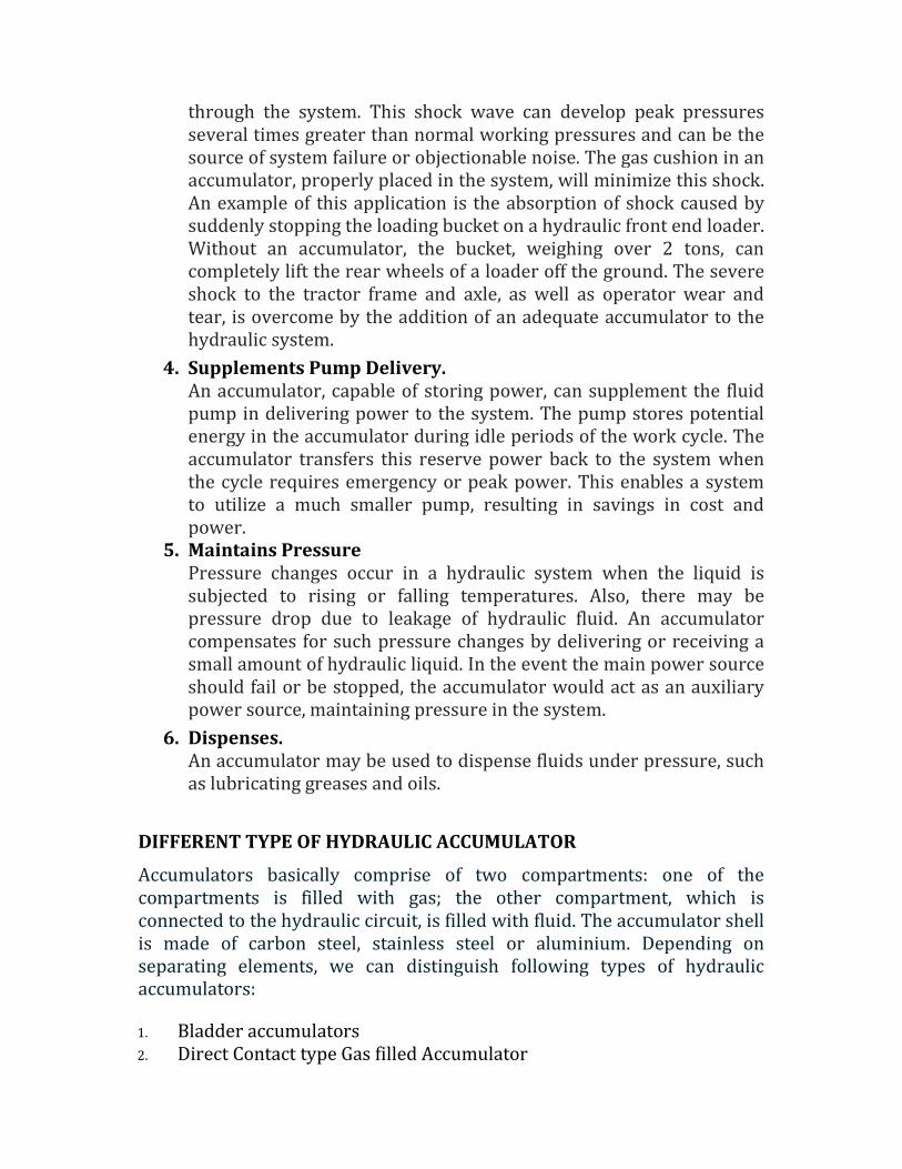
BLADDER ACCULUMATOR
A bladder accumulator is the most commonly used hydro-pneumatic
accumulator. The bladder is filled with nitrogen and fitted in a welded or
forged steel pressure vessel. The bladder is made of an elastic material
(elastomer), e.g. rubber. The gas pre-charge pressure can be adapted via
the gas inlet/outlet valve on top of the bladder accumulator.
If the bladder accumulator is mounted vertically or at an angle, the gas side
must always be on top. When the pressure drops, the compressed gas in
the bladder expands and pushes the stored fluid into the hydraulic circuit.
At zero pressure, the bladder may be pushed out of the pressure vessel. To
prevent this, a spring-loaded valve is provided on the fluid side.
The bladder accumulator is used when a high power output is required.
Specially designed bladder accumulators are capable of operating at
maximum pressures of up to 1,000 bars. The gas volume and effective
hydraulic volume is medium, ranging from 0.5 l to 450 l. Fig-1
Fig-1
Advantage: Highest efficiency with tests showing 97 percent energy
retainment.
Disadvantage: Nitrogen will permeate the foam bladder material over
time and need to be periodically recharged.
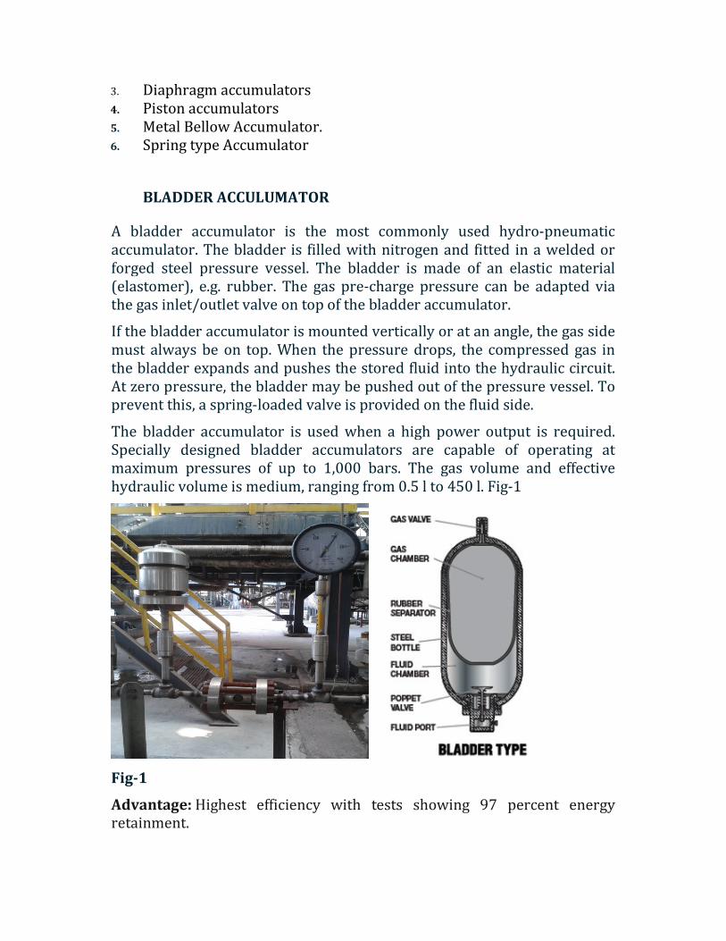
DIRECT CONTACT TYPE GAS FILLED ACCUMULATORS
Direct-contact gas-to-fluid accumulators generally are used in very large
installations where it would be very expensive to require a piston-or
bladder-type accumulator. This type of accumulator consists of a fully
enclosed cylinder, mounted in a vertical position, containing a liquid.
Fig-2
Ammonia Feed pump suction dampener act as direct contact accumulator
because the steam jacketed on top portion, so that the vaporized ammonia
pushed the liquid ammonia.

Fig-3
DIAPHRAGM ACCUMULATOR
These accumulators have a rubber plate or diaphragm as the separating
element the diaphragm-type accumulator is constructed in two halves
which are either screwed or bolted together. A synthetic rubber diaphragm
is installed between both halves, making two chambers. The compartment
above the diaphragm is filled with nitrogen. Two threaded openings exist in
the assembled component. Contains a screen disc which prevents the
diaphragm from extruding through the threaded opening when system
pressure is depleted, thus rupturing the diaphragm. On some designs the
screen is replaced by a button-type protector fastened to the center.These
accumulators have a rubber plate or diaphragm as the separating element.
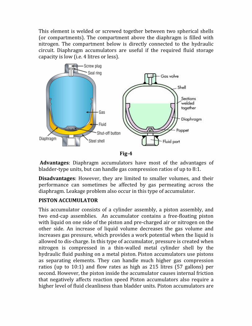
This element is welded or screwed together between two spherical shells
(or compartments). The compartment above the diaphragm is filled with
nitrogen. The compartment below is directly connected to the hydraulic
circuit. Diaphragm accumulators are useful if the required fluid storage
capacity is low (i.e. 4 litres or less).
Fig-4
Advantages: Diaphragm accumulators have most of the advantages of
bladder-type units, but can handle gas compression ratios of up to 8:1.
Disadvantages: However, they are limited to smaller volumes, and their
performance can sometimes be affected by gas permeating across the
diaphragm. Leakage problem also occur in this type of accumulator.
PISTON ACCUMULATOR
This accumulator consists of a cylinder assembly, a piston assembly, and
two end-cap assemblies. An accumulator contains a free-floating piston
with liquid on one side of the piston and pre-charged air or nitrogen on the
other side. An increase of liquid volume decreases the gas volume and
increases gas pressure, which provides a work potential when the liquid is
allowed to dis-charge. In this type of accumulator, pressure is created when
nitrogen is compressed in a thin-walled metal cylinder shell by the
hydraulic fluid pushing on a metal piston. Piston accumulators use pistons
as separating elements. They can handle much higher gas compression
ratios (up to 10:1) and flow rates as high as 215 litres (57 gallons) per
second. However, the piston inside the accumulator causes internal friction
that negatively affects reaction speed Piston accumulators also require a
higher level of fluid cleanliness than bladder units. Piston accumulators are

used for very large fluid storage requirements of up to 2,500 litres at very
high pressures (up to 1,000 bar).
Fig-5
Advantage: Virtually no nitrogen escapes so they will not have to be
recharged.
Disadvantage: A bit heavier, and less efficient than the bladder mod, they
are more susceptible to fluid contamination. Lower response time than the
bladder and diaphragm.
METAL BELLOW ACCUMULATOR
Metal bellows are used in variety of industries to store the energy of liquid
or gas The metal bellows accumulator is similar to bladder type, expect the
elastic is replaced by a hermitically sealed welded metal bellows. Fluid may
be internal or external to the bellows internal. It is used when a fast
response time is not critical, yet reliability is important. Metal bellow types
are pre-charged by supplier and then permanently sealed leading to
maintenance free accumulators.

Fig-6
Advantages.
Metal bellow type include exceptionally low spring rate, allowing the gas
charge to do all the work with little change in pressure from full to empty,
and long stroke relative solid height, which gives maximum storage volume
for a given container size. It provides exceptionally high level accumulator
performance. It can be produced with broad spectrum of alloys resulting
broad range of fluid compatibility.
Disadvantages.
Response time is more & high cost.
SPRING TYPE ACCUMULATOR
It uses the energy stored in springs to create a constant force on the liquid
contained in an adjacent ram assembly. The load characteristics of a spring
are such that the energy storage depends on the force required to compress
s spring. The free (uncompressed) length of a spring represents zero
energy storage. As a spring is compressed to the maximum installed length,
high pressure value of the liquid in a ram assembly is established. As liquid
under pressure enters the ram cylinder, causing a spring to compress, the
pressure on the liquid will rise because of the increased loading required to
compress the spring.

Fig-7
CONCLUSION
So what are the benefits of using accumulators? Lower installed system
costs, accumulator assisted hydraulics can reduce the size of the pump and
electric motor which results in a smaller amount of oil used, a smaller
reservoir and reduced equipment costs. Less leakage and maintenance
costs, the ability to reduce system shocks will prolong component life,
reduce leakage from pipe joints and minimize hydraulic system
maintenance costs. Improved performance, low inertia bladder
accumulators can provide instantaneous response time to meet peak flow
requirements. They can also help to achieve constant pressure in systems
using variable displacement pumps for improved productivity and quality.
*************************************