Embed Size (px)
Citation preview

Design Considerations for
Food Irradiators
PREETI BIRWAL
PH.D (NDRI)
DEPT. OF DAIRY ENGINEERING
Introduction
Food irradiation is a relatively new revolutionary process with essentially
the same objectives as those of the traditional methods of food preservation
i.e., extending shelf-life and reducing the incidence of food-borne disease.
All food irradiators must expose the product to the radiation source
effectively; the radiation may be either from 60Co or machine - generated.
Many factors influence the design of a food irradiator and the choice of the
radiation source.
The major considerations include the uniformity of the distribution of the
absorbed dose in the given product, efficient utilization of the radiation
energy, and cost - effectiveness based on minimizing the combined capital
and operating costs

Larger in size are pilot irradiators capable of conducting research, but they are mainly for
irradiating large quantities of products for feeding tests, shipping studies, and commercial
feasibility studies. Two examples of these are the Hawaii Development Irradiator built with
the support of the then U.S. Atomic Energy Commission (AEC) in Honolulu in 1967, with
an initial loading of 200 kCi of Co-60. Large quantities of papayas were irradiated, made
into puree, and shipped to a U.S. laboratory in Illinois for animal feeding studies on safety.
Another irradiator was the U.S. Marine Fisheries Irradiator, also built with AEC support in
the mid-1960s at Gloucester, MA, for irradiation study of marine species. Two pilot electron
accelerators were funded by the U.S. Department of Energy in the late 1980s under the
program called Agriculture Demonstration Irradiators.
One was installed at the Plant Industry Division of the Florida Department of agriculture and
Consumer Services in Gainesville and another at Iowa State University in Ames. Both of
these were made in France. The one in Ames, Iowa, can operate in both electron beam mode
and x-ray mode. In 2001, Texas A & M University installed a pilot e-beam facility for
research and development.
Commercial Co-60 irradiators with initial loading of 500 kCi to several million curies have
been built around the world, mainly for sterilizing disposable medical supplies and some
cosmetics. Most electron accelerators have also been installed for industrial uses, such as the
cable and plastic industry
IRRADIATOR SELECTION CRITERIA
For the efficient operation of the irradiation facility, it is critical that the
requirements of the intended applications are clearly understood before the facility is
designed and built. When listing the requirements, it is essential that not only the
present needs are considered but also the future ones (but realistic) are included.
selection process is : –
Type of product to be irradiated (size, density, homogeneity),
Seasonality of product (some food products may be seasonal),
Dose and dose uniformity requirements for the intended product(s) and process,
Throughput requirement, product density can affect throughput.
Is the irradiator part of a manufacturing or other process, or a service facility, and
Is this a single or a multi purpose facility.

Besides these technical criteria, there are others that should also be
considered during the selection process.
These include: –
Capital and operating cost of the total facility,
Utility requirements such as electrical power and water supply, and
Technical expertise available in the region, including human resources.
Depending on the national regulations of the country, it would be necessary
to obtain a license to construct and operate the facility. Several departments
or ministries could be involved depending on the product to be processed,
such as atomic energy authority, health ministry, food ministry, industry
ministry, etc.
Types of Irradiators
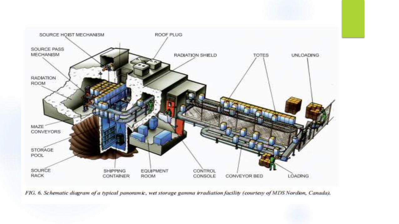
Panoramic dry source storage irradiators
Underwater irradiators, in which both the source and the product being
irradiated are under water.
Panoramic wet source storage irradiators.
Electron beam irradiation facilities, in which irradiation is performed in an
area that is potentially accessible to personnel, but that is kept inaccessible
during the irradiation process.
X ray irradiation facilities, in which irradiation is performed in an area
that is potentially accessible to personnel, but that is kept inaccessible
during the irradiation process.
The irradiation treatment can be conducted in either a batch or continuous
mode. The batch method is simpler to design, easier to operate and is
more flexible.
The continuous operation is more suitable for large volumes. It may
involve a single-pass or a multiple pattern, the design of which allows a
more uniform exposure of the food and a more efficient use of the
source.
Mobile irradiators are also available. These are compact units which are best
suited for certain foods where season, location, transport and interval
between harvest and processing, may be limiting factors, e.g., sea foods.
The design should allow easy changing from one product to another without
any product receiving doses outside the allowable limits.
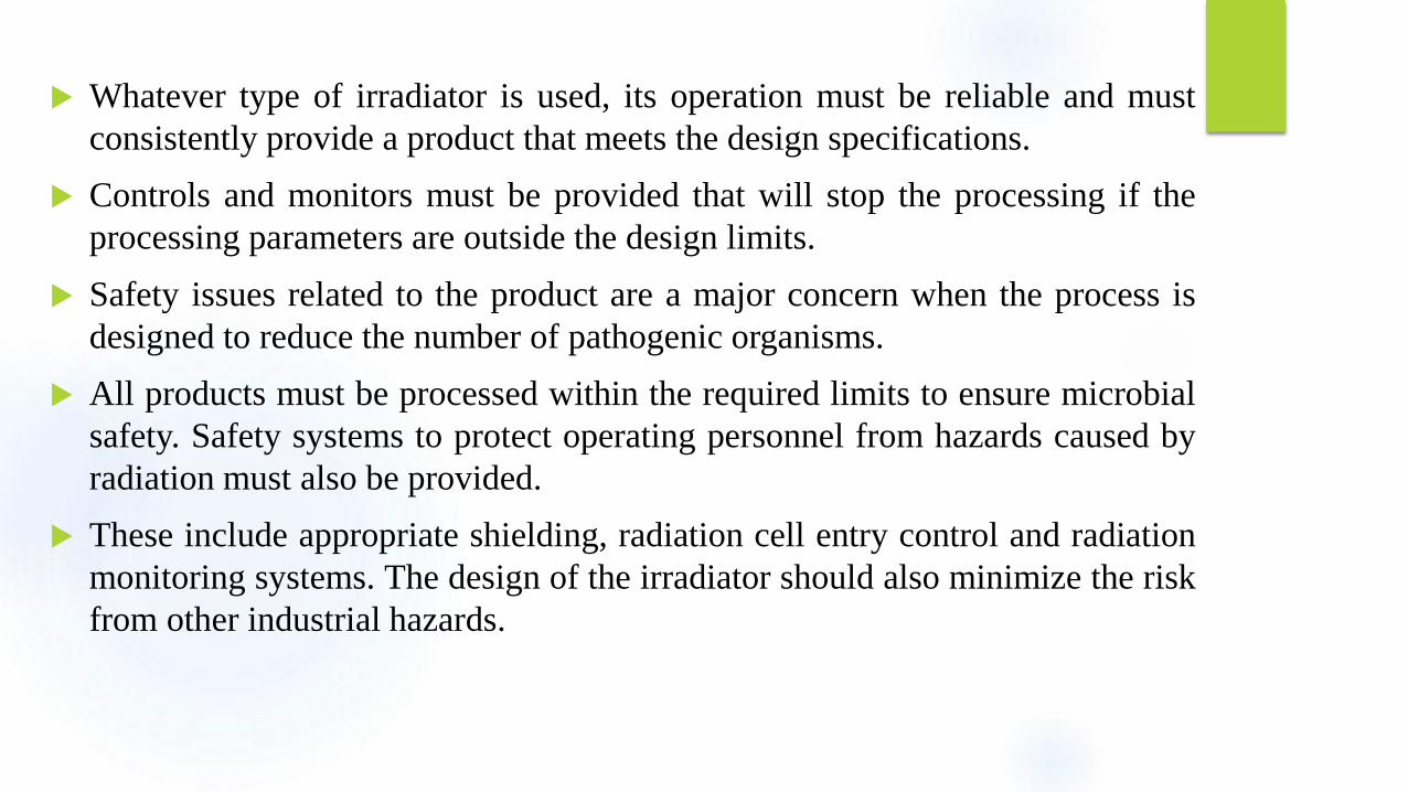
Whatever type of irradiator is used, its operation must be reliable and must
consistently provide a product that meets the design specifications.
Controls and monitors must be provided that will stop the processing if the
processing parameters are outside the design limits.
Safety issues related to the product are a major concern when the process is
designed to reduce the number of pathogenic organisms.
All products must be processed within the required limits to ensure microbial
safety. Safety systems to protect operating personnel from hazards caused by
radiation must also be provided.
These include appropriate shielding, radiation cell entry control and radiation
monitoring systems. The design of the irradiator should also minimize the risk
from other industrial hazards.

Design Requirement
Wiring
Source return
Fire protection
Access control
Source rack
Radiation monitors
Water handling system
Shielding
Foundations

Cobalt Irradiators
The 60 Co source elements are usually in the form of cylindrical pencils.
A number of source pencils may be installed into individual modules to simplify the
handling of the source.
The modules are then distributed in a rack to form the desired source array. For
panoramic irradiators with sources stored in a water - filled pool, the source handling is
usually performed underwater.
Source elements, source modules and a typical rectangular source rack.
The size of the source rack should be sufficient to allow the addition of source pencils
without requiring the return of source pencils until the end of their working life.
Generally, a source rack is designed to allow the addition of new source pencils without
removing sources for approximately 20 years.
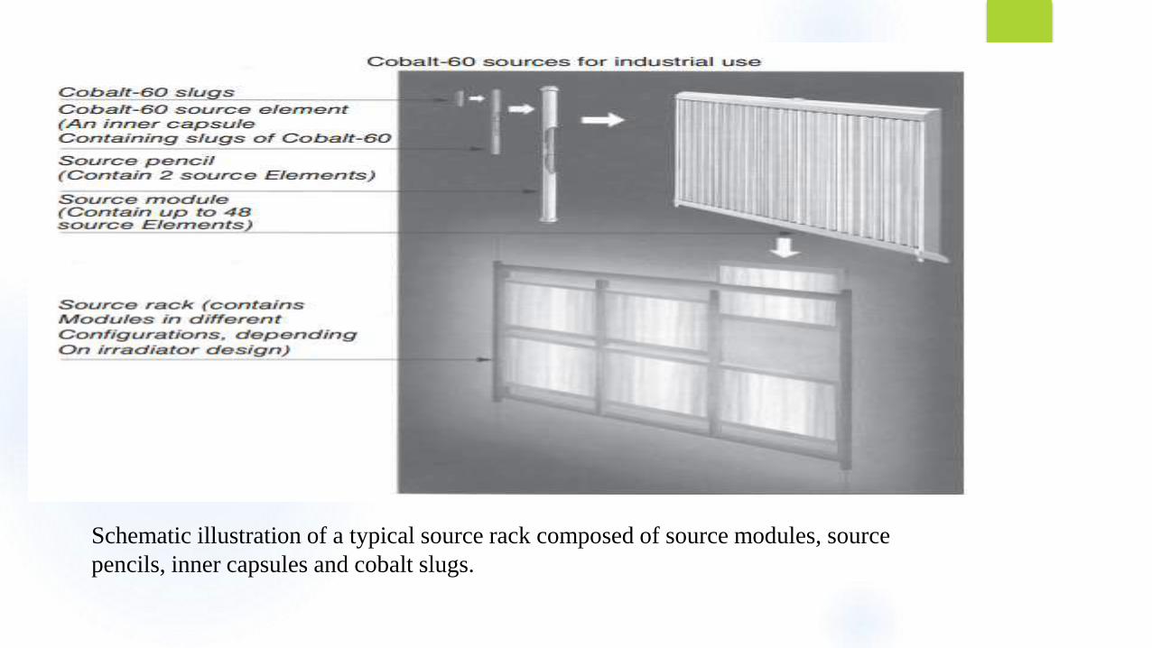
Schematic illustration of a typical source rack composed of source modules, source
pencils, inner capsules and cobalt slugs.
In many 60Co irradiator designs, the product is moved in parallel
rows on both sides of a vertical rectangular source rack. The product
may move at a controlled speed or may spend specified time
increments in different static locations (shuffle dwell).
The drive mechanism for moving the product may be pneumatic,
hydraulic or electric.
The product can be loaded into individual metal containers (totes)
and transported on conveyors, or it can be loaded into hanging
containers (carriers) for transport past the source.
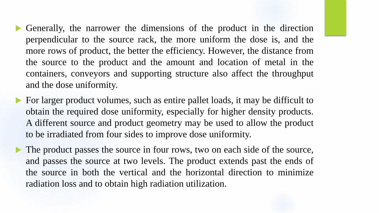
Generally, the narrower the dimensions of the product in the direction
perpendicular to the source rack, the more uniform the dose is, and the
more rows of product, the better the efficiency. However, the distance from
the source to the product and the amount and location of metal in the
containers, conveyors and supporting structure also affect the throughput
and the dose uniformity.
For larger product volumes, such as entire pallet loads, it may be difficult to
obtain the required dose uniformity, especially for higher density products.
A different source and product geometry may be used to allow the product
to be irradiated from four sides to improve dose uniformity.
The product passes the source in four rows, two on each side of the source,
and passes the source at two levels. The product extends past the ends of
the source in both the vertical and the horizontal direction to minimize
radiation loss and to obtain high radiation utilization.
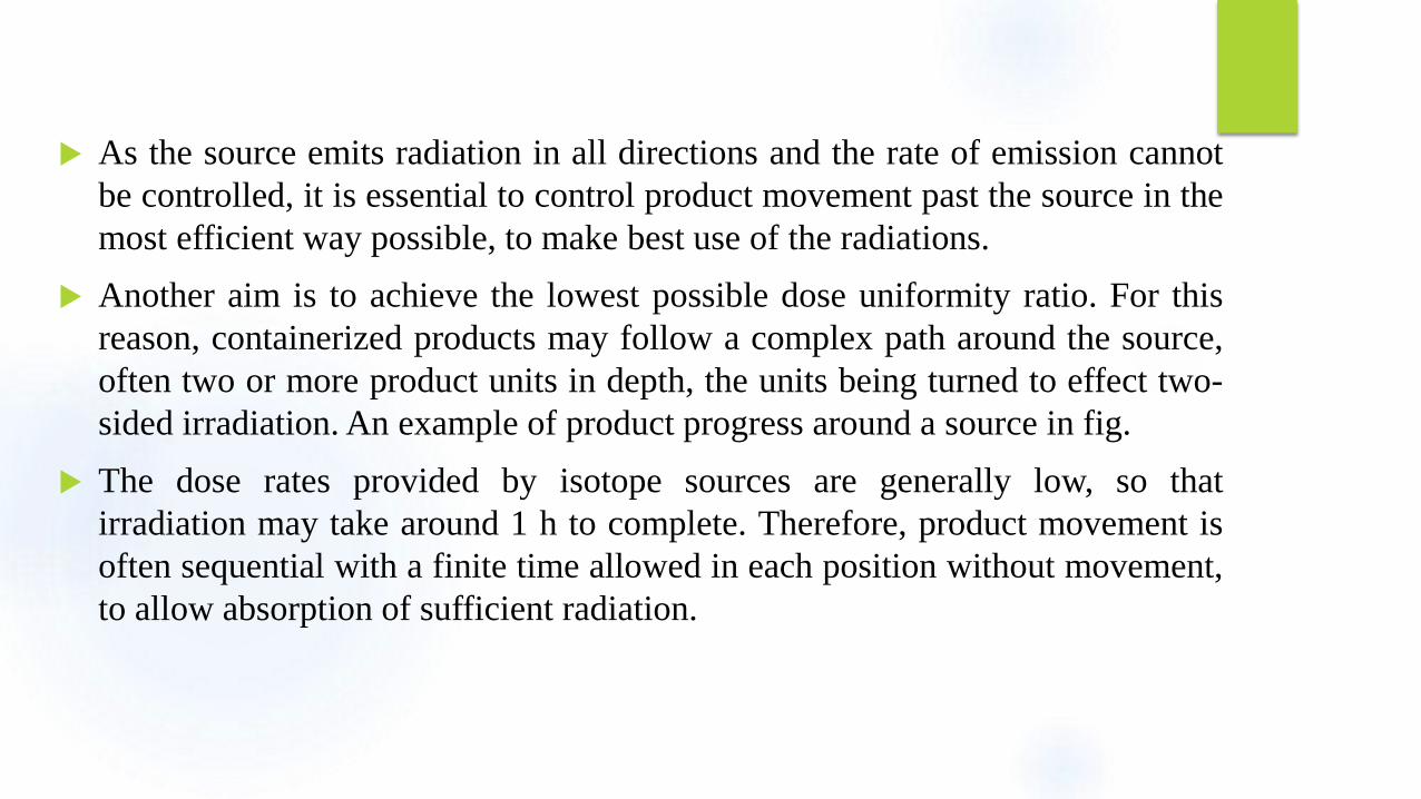
As the source emits radiation in all directions and the rate of emission cannot
be controlled, it is essential to control product movement past the source in the
most efficient way possible, to make best use of the radiations.
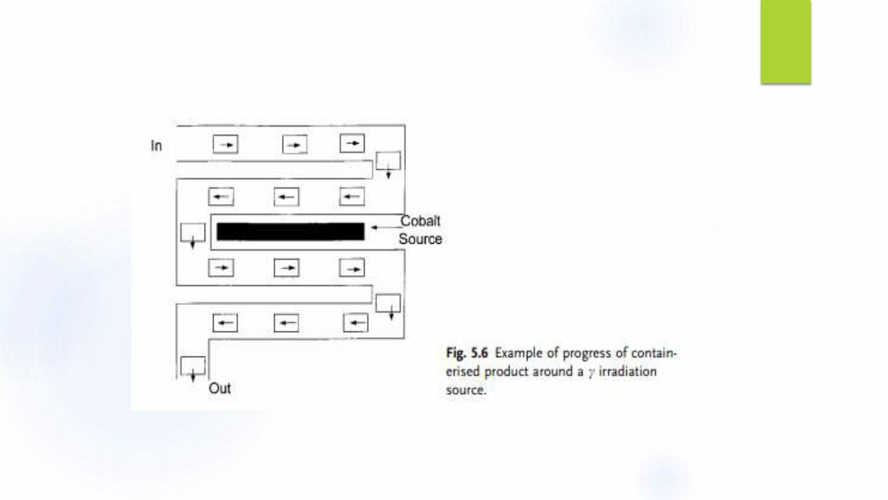
Another aim is to achieve the lowest possible dose uniformity ratio. For this
reason, containerized products may follow a complex path around the source,
often two or more product units in depth, the units being turned to effect two-
sided irradiation. An example of product progress around a source in fig.
The dose rates provided by isotope sources are generally low, so that
irradiation may take around 1 h to complete. Therefore, product movement is
often sequential with a finite time allowed in each position without movement,
to allow absorption of sufficient radiation.
Electron Beam Irradiators
The main designs of electron irradiator available are the Dynamitron, which willproduce electron energies up to 4.5 MeV, or linear accelerators for higherenergies.
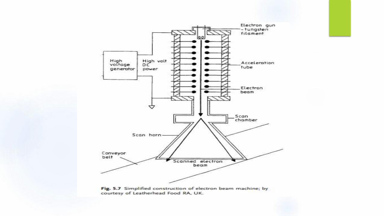
In either case, the resulting beam diameter is only a few millimeters orcentimeters. To allow an even dose distribution in the product, it is necessary toscan the beam using a scanning magnet, which creates an alternating magneticfield (analogous to the horizontal scan of a television tube) which moves the beamback and forwards at 100–200 Hz.
An even, fan-shaped field of emitted electrons is created, through which the foodis conveyed. A simplified diagram of an electron beam machine.
For electron beam irradiators, the product is usually transported at a controlledspeed past a scanned beam of electrons. Because the electrons are stopped by ashort depth of product, the irradiation zone is usually small and the dose isdelivered in a very short time.
the low penetration of electrons requires that this technology is limited either to
surface treatment of food or to foods of limited thickness (8 cm max., with two-
sided irradiation).
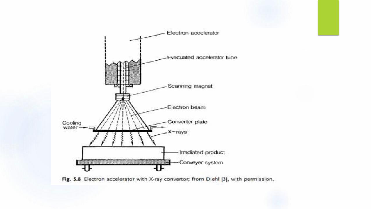
When electrons strike a target, they produce X-rays which can be utilized to give
greater penetration depth, but which suffer from the disadvantage of a low
conversion efficiency. The efficiency of conversion depends on the energy of the
electrons and the atomic number of the target material. In practice, therefore, X-rays
are produced by firing high-energy electrons at a heavy metal target plate, as shown
schematically in Fig. 5.8.
Even with 10 MeV electrons and a tungsten (atomic number 74) plate, the efficiency
of conversion is only 32%, hence cooling water must be applied to the converter
plate.
Both electrons and X-rays deliver much higher dose rates than isotope sources, so
that processing is complete in a matter of seconds. Also the beams may be directed,
so that the complex transport of packages around the source is not required.
Special features: There may be specific requirements for some processes that could be incorporated in some of
these designs.
Irradiation of products in frozen or chilled condition: This is generally accomplished by
the use of insulated containers.
Incremental dose delivery: For a continuous mode of operation, this feature allows
irradiating products with different dose requirements together. Products requiring less dose
exit the irradiation room after less number of revolutions, while other products continue to
go around the source for more dose.
Low absorbed-dose applications: Because of mechanical speed limitations, various
techniques may be used to reduce the absorbed-dose rates for such processes. These
techniques include using only a portion of the source (e.g. raising one of several source
racks to the irradiation position), using attenuators, and irradiating at greater distances
from the source (which may be a separate loop)


![Failed Gamma Beam Irradiator - HPS Chapters Penland.pdfMicrosoft PowerPoint - GBI Presentation-Oakland.ppt [Compatibility Mode] Author: mtbecker Created Date: 6/6/2008 11:43:09 AM](https://img.pdfslide.us/doc/110x75/5ffa56e6e2d034611d08515e/failed-gamma-beam-irradiator-hps-penlandpdf-microsoft-powerpoint-gbi-presentation-oaklandppt.jpg)