Embed Size (px)
Citation preview
Introduction to Microcontroller
Eng:Mohamed Loay Ali Eng:Khaled Khamis
1
Contents
• Types of Controllers.
• Types of Compilers.
• AVR DataSheet.
• AVR input/output Configuration.
• Writing First Code in AVR.
• Transfer First Program to AVR.
• Switch Debouncing (Case Study).
Eng:Mohamed Loay Ali Eng:Khaled Khamis
2
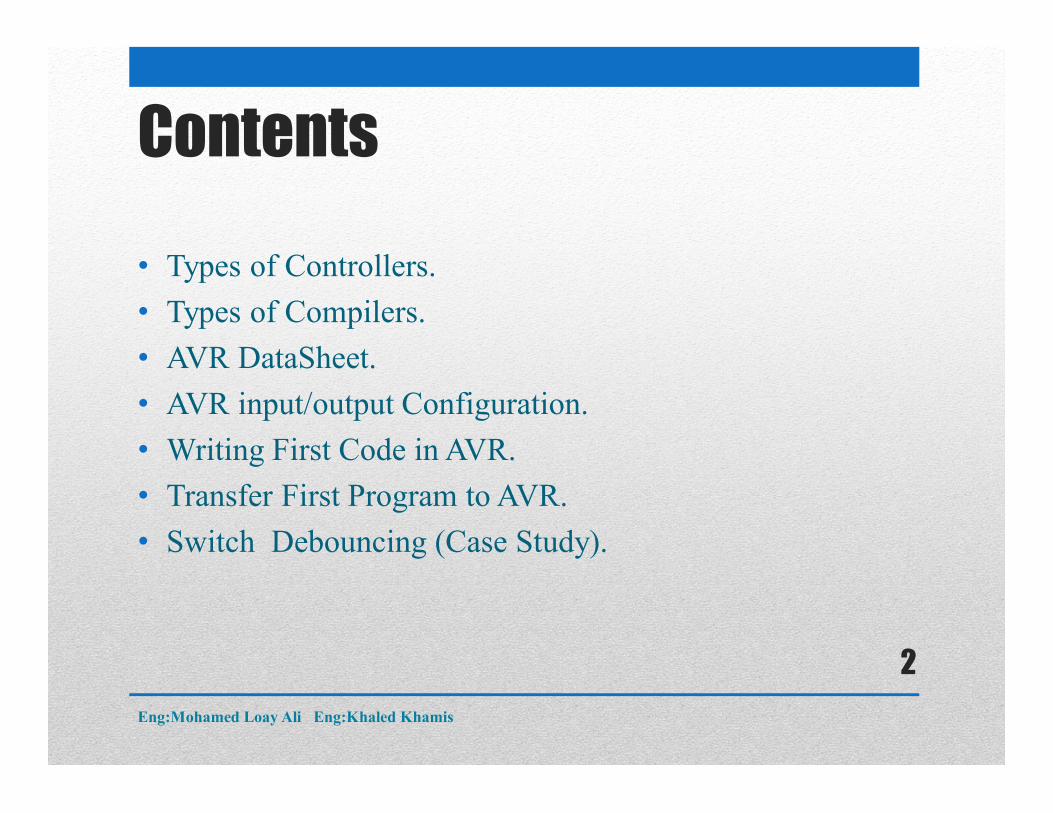
Types of Controllers1)Microprocessor based Systems:Industrial PC, u computer , mainframes
Eng:Mohamed Loay Ali Eng:Khaled Khamis
3
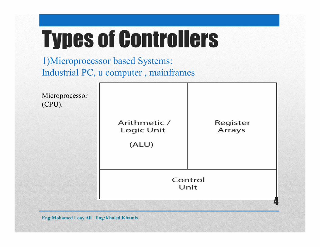
Types of Controllers1)Microprocessor based Systems:Industrial PC, u computer , mainframes
Microprocessor (CPU).
Eng:Mohamed Loay Ali Eng:Khaled Khamis
4
Types of Controllers1)Microprocessor based Systems:Industrial PC, u computer , mainframes
Microprocessor Architecture:
Eng:Mohamed Loay Ali Eng:Khaled Khamis
5
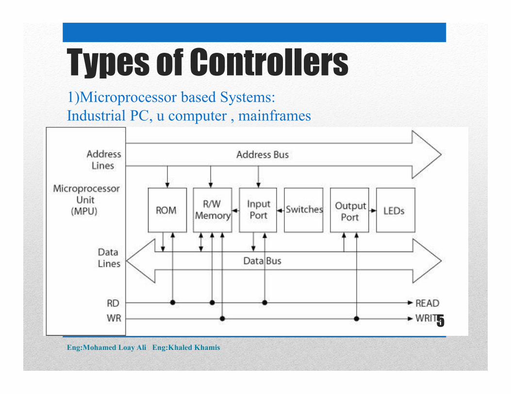
Types of Controllers1)Microprocessor based Systems:Industrial PC, u computer , mainframes
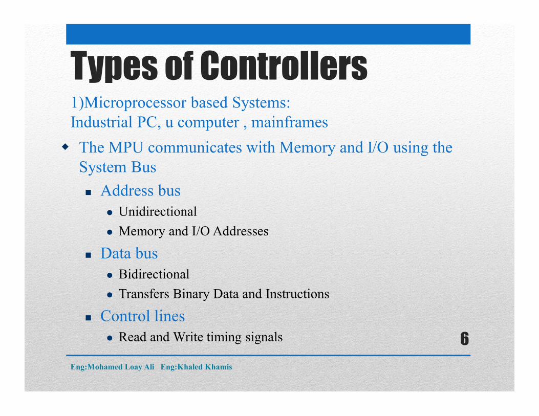
The MPU communicates with Memory and I/O using the System Bus
Address bus Unidirectional
Memory and I/O Addresses
Data bus Bidirectional
Transfers Binary Data and Instructions
Control lines Read and Write timing signals
Eng:Mohamed Loay Ali Eng:Khaled Khamis
6
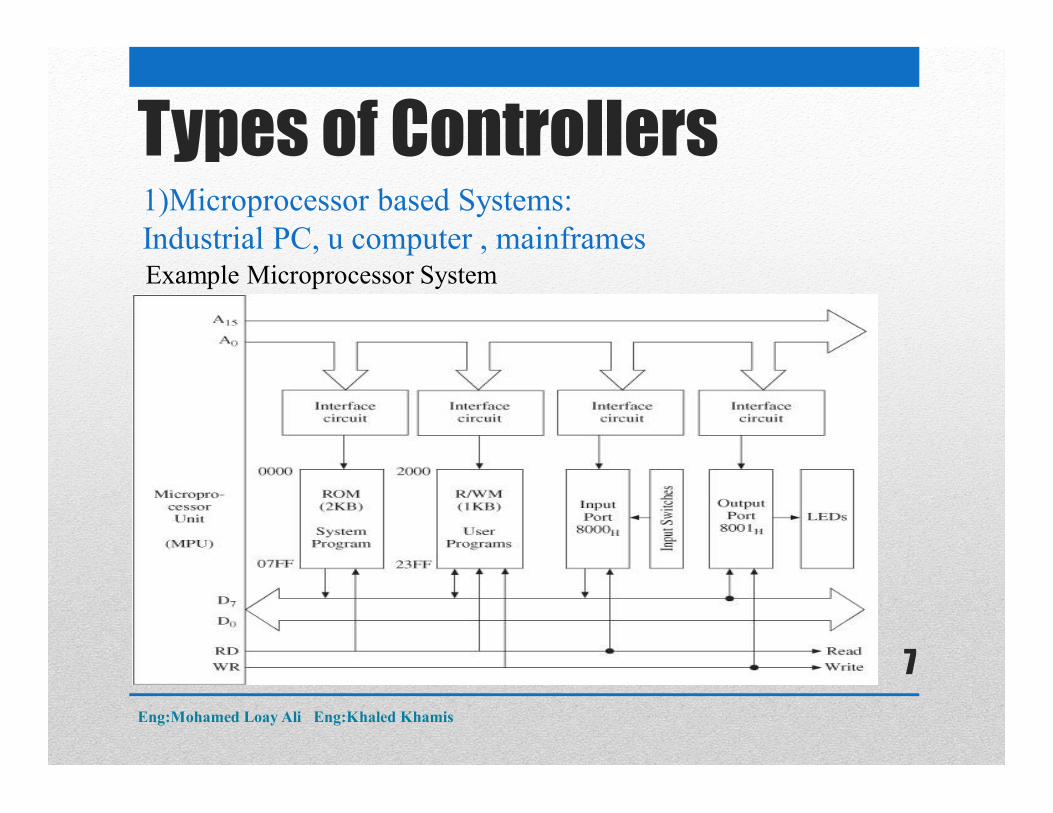
Example Microprocessor System
Types of Controllers1)Microprocessor based Systems:Industrial PC, u computer , mainframes
Eng:Mohamed Loay Ali Eng:Khaled Khamis
7
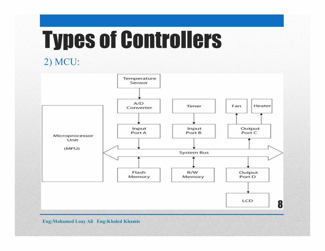
Types of Controllers2) MCU:
Eng:Mohamed Loay Ali Eng:Khaled Khamis
8
Types of Controllers2) MCU:
System hardware
Discrete components Microprocessor, Memory, and I/O
Components connected by buses Address, Data, and Control
System software
A group of programs that monitors the functions of the entire system
Eng:Mohamed Loay Ali Eng:Khaled Khamis
9
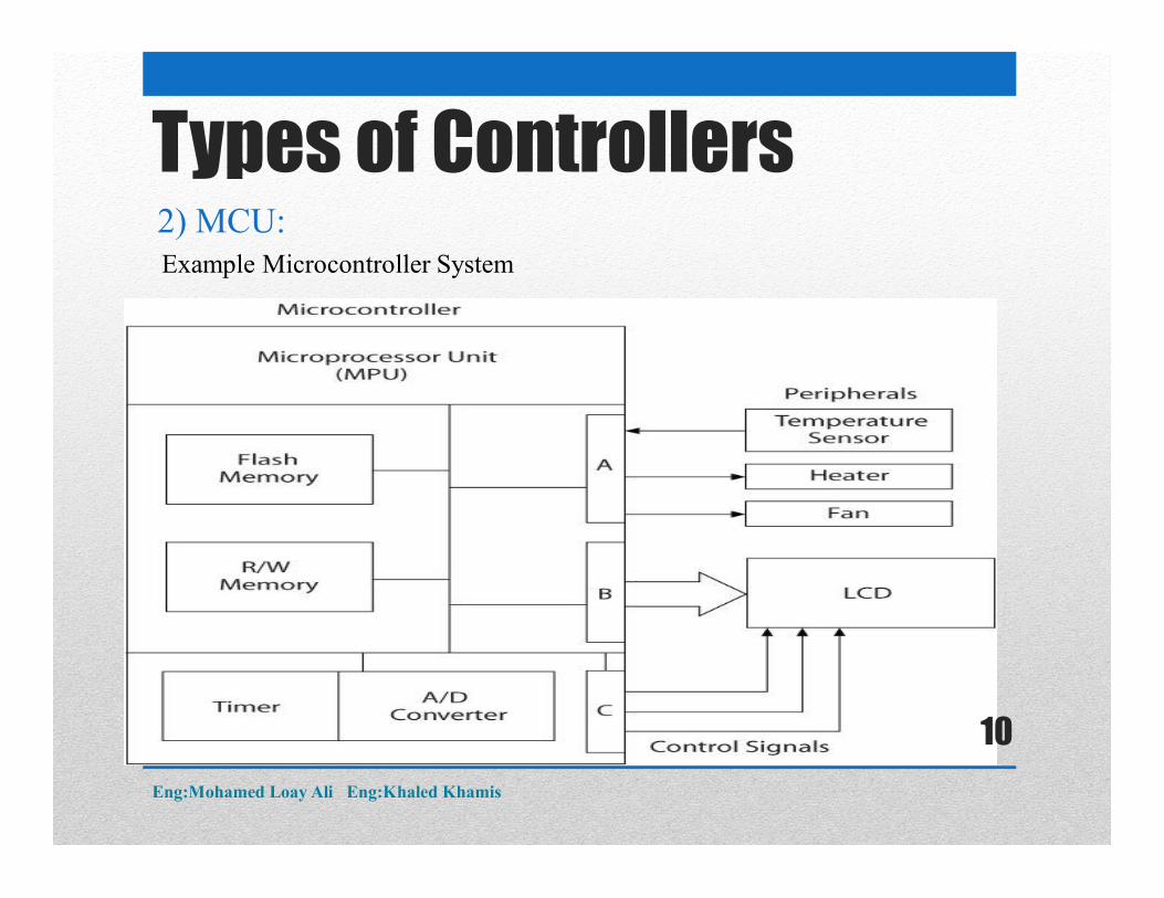
Types of Controllers2) MCU:Example Microcontroller System
Eng:Mohamed Loay Ali Eng:Khaled Khamis
10
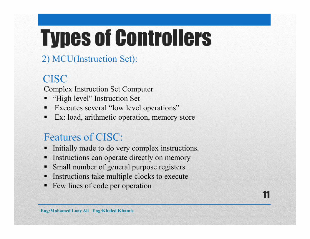
CISCComplex Instruction Set Computer “High level" Instruction Set Executes several “low level operations” Ex: load, arithmetic operation, memory store
Features of CISC: Initially made to do very complex instructions. Instructions can operate directly on memory Small number of general purpose registers Instructions take multiple clocks to execute Few lines of code per operation
Types of Controllers2) MCU(Instruction Set):
Eng:Mohamed Loay Ali Eng:Khaled Khamis
11
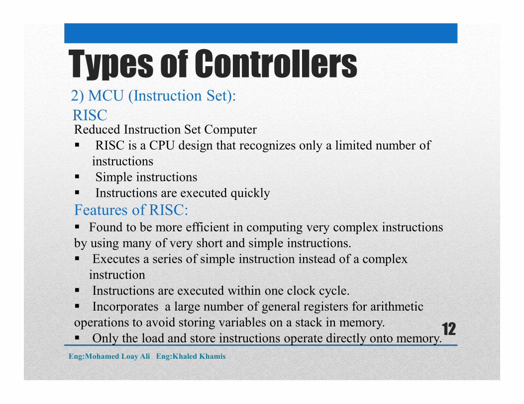
RISCReduced Instruction Set Computer RISC is a CPU design that recognizes only a limited number of
instructions Simple instructions Instructions are executed quickly
Features of RISC: Found to be more efficient in computing very complex instructions by using many of very short and simple instructions. Executes a series of simple instruction instead of a complex
instruction Instructions are executed within one clock cycle. Incorporates a large number of general registers for arithmetic operations to avoid storing variables on a stack in memory. Only the load and store instructions operate directly onto memory.
Types of Controllers2) MCU (Instruction Set):
Eng:Mohamed Loay Ali Eng:Khaled Khamis
12
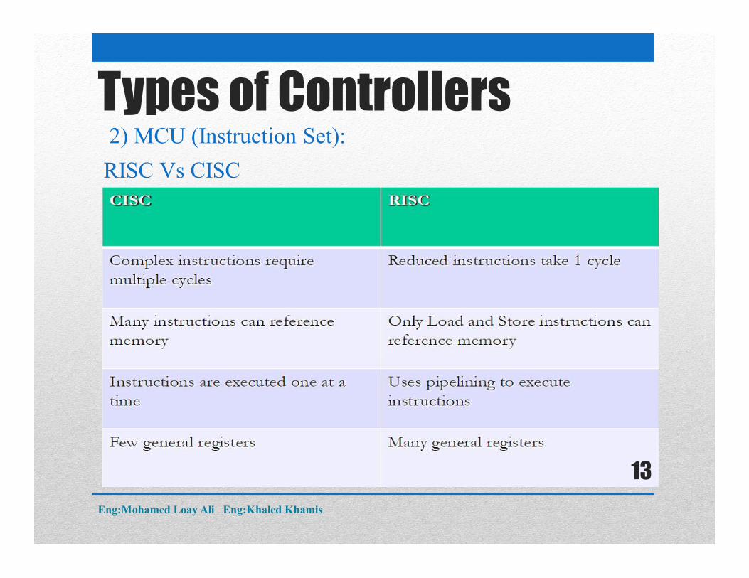
RISC Vs CISC
Types of Controllers2) MCU (Instruction Set):
Eng:Mohamed Loay Ali Eng:Khaled Khamis
13
Register File: A (usually) relatively small memory embedded on the CPU. It is used as a scratchpad for temporary storage of values the CPU is working with you could call it the CPU’s short term memory.
Data Memory: For longer term storage, generic CPUs usually employ an external memory which is much larger than the register file. Data that is stored there may be short-lived, but may also be valid for as long as the CPU is running
Instruction Memory: Like the data memory, the instructionmemory is usually a relatively large external memory (atleast with general CPUs)
Types of Controllers2) MCU(Memory Types):
Eng:Mohamed Loay Ali Eng:Khaled Khamis
14
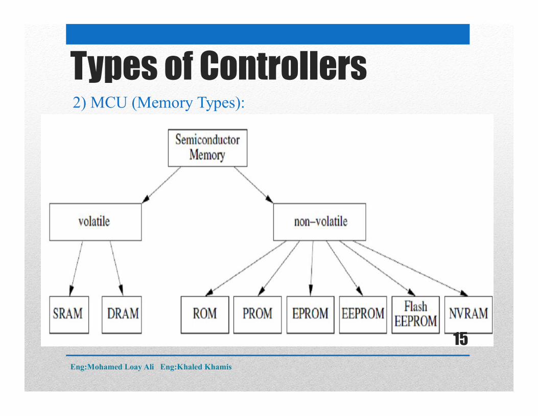
Types of Controllers2) MCU (Memory Types):
Eng:Mohamed Loay Ali Eng:Khaled Khamis
15
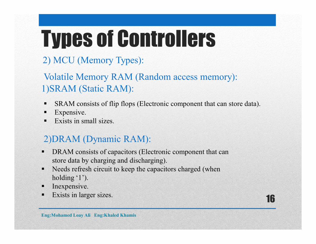
Volatile Memory RAM (Random access memory):1)SRAM (Static RAM):
SRAM consists of flip flops (Electronic component that can store data). Expensive. Exists in small sizes.
DRAM consists of capacitors (Electronic component that can store data by charging and discharging).
Needs refresh circuit to keep the capacitors charged (when holding ‘1’).
Inexpensive. Exists in larger sizes.
2)DRAM (Dynamic RAM):
Types of Controllers2) MCU (Memory Types):
Eng:Mohamed Loay Ali Eng:Khaled Khamis
16
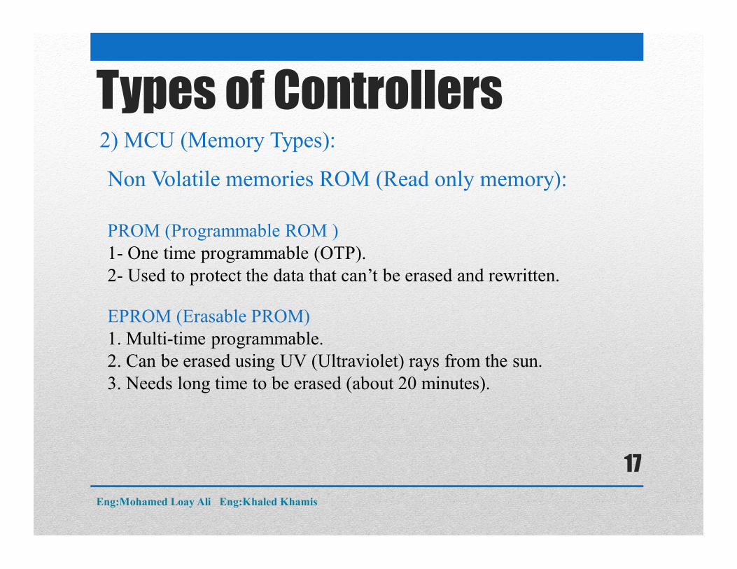
Non Volatile memories ROM (Read only memory):
PROM (Programmable ROM )1- One time programmable (OTP).2- Used to protect the data that can’t be erased and rewritten.
EPROM (Erasable PROM)1. Multi-time programmable.2. Can be erased using UV (Ultraviolet) rays from the sun.3. Needs long time to be erased (about 20 minutes).
Types of Controllers2) MCU (Memory Types):
Eng:Mohamed Loay Ali Eng:Khaled Khamis
17
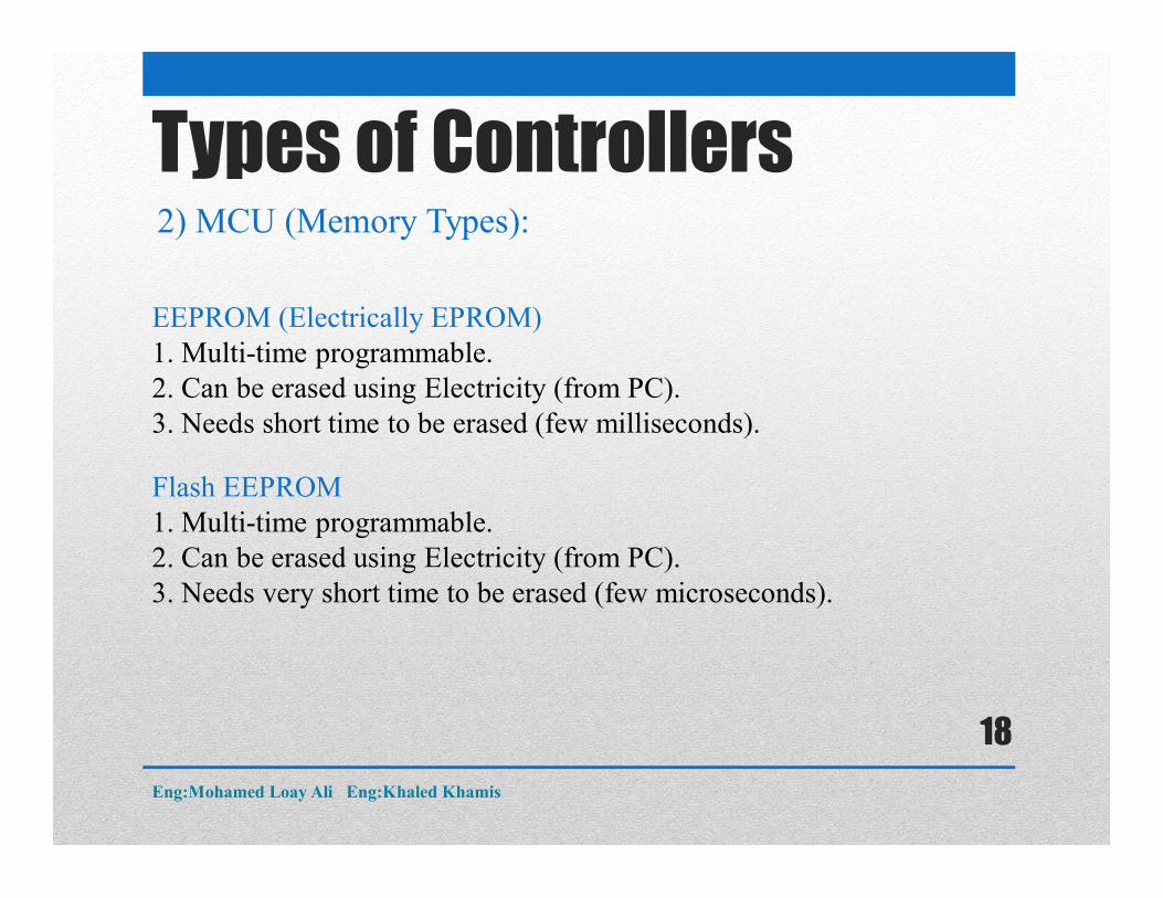
EEPROM (Electrically EPROM)1. Multi-time programmable.2. Can be erased using Electricity (from PC).3. Needs short time to be erased (few milliseconds).
Flash EEPROM1. Multi-time programmable.2. Can be erased using Electricity (from PC).3. Needs very short time to be erased (few microseconds).
Types of Controllers2) MCU (Memory Types):
Eng:Mohamed Loay Ali Eng:Khaled Khamis
18
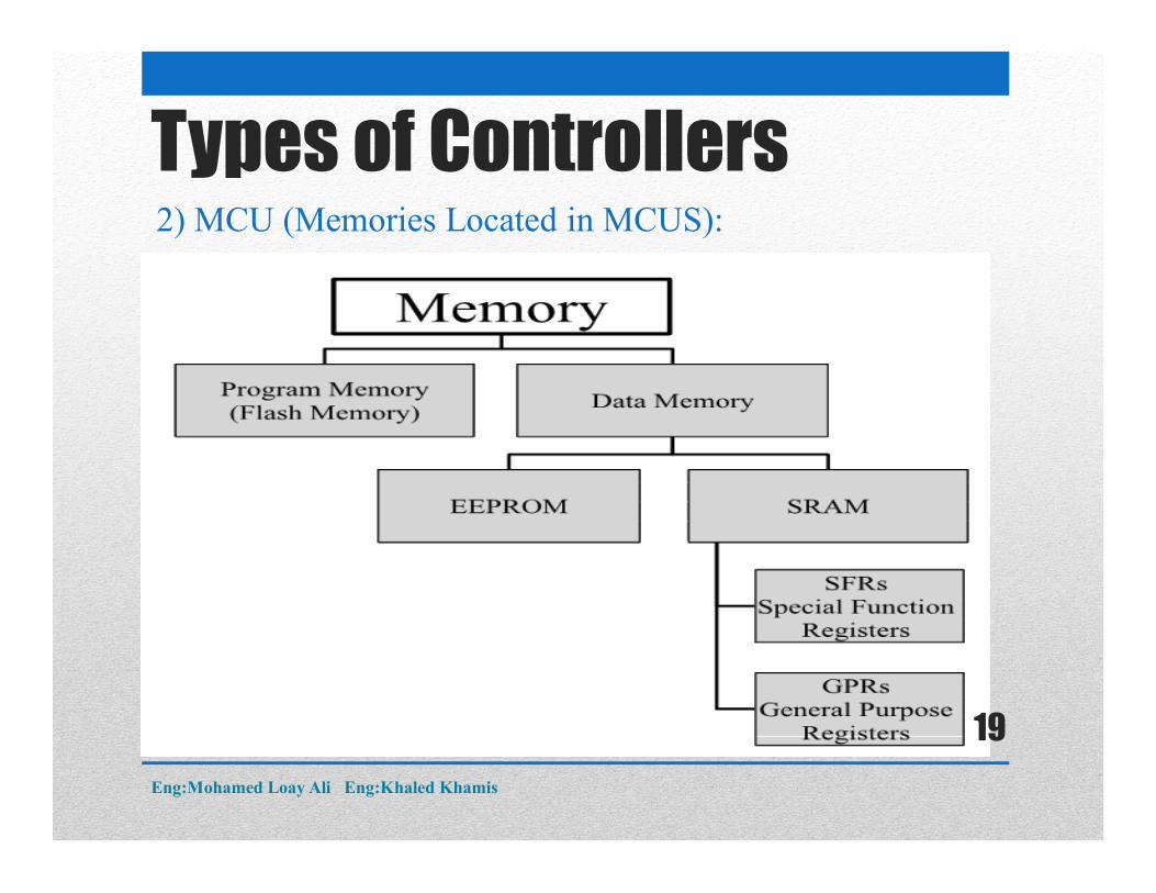
Types of Controllers2) MCU (Memories Located in MCUS):
Eng:Mohamed Loay Ali Eng:Khaled Khamis
19
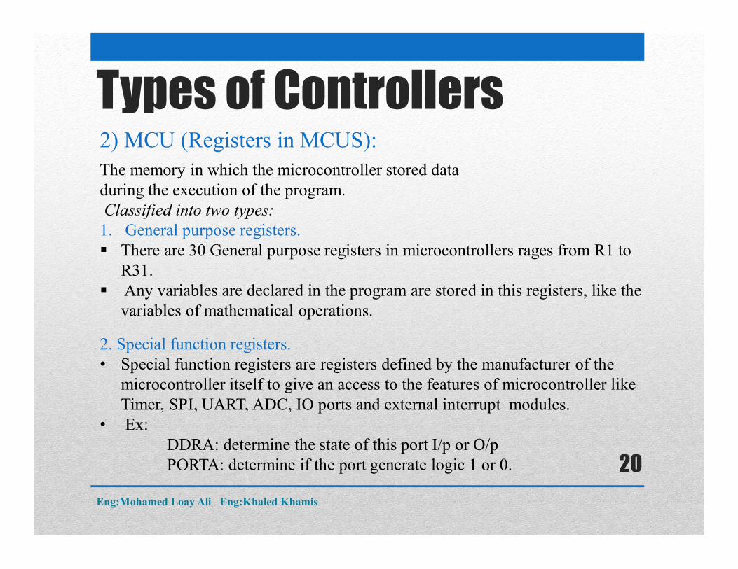
Types of Controllers2) MCU (Registers in MCUS): The memory in which the microcontroller stored data during the execution of the program.Classified into two types:
1. General purpose registers. There are 30 General purpose registers in microcontrollers rages from R1 to
R31. Any variables are declared in the program are stored in this registers, like the
variables of mathematical operations.
2. Special function registers.• Special function registers are registers defined by the manufacturer of the
microcontroller itself to give an access to the features of microcontroller like Timer, SPI, UART, ADC, IO ports and external interrupt modules.
• Ex:DDRA: determine the state of this port I/p or O/pPORTA: determine if the port generate logic 1 or 0.
Eng:Mohamed Loay Ali Eng:Khaled Khamis
20
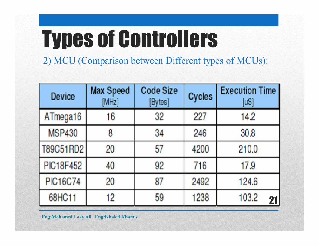
Types of Controllers2) MCU (Comparison between Different types of MCUs):
Eng:Mohamed Loay Ali Eng:Khaled Khamis
21
Types of Controllers3)DSP (Digital Signal Processor):
Advantages of DSP Conventional DSP devices are well-suited to a wide range of
applications requiring mathematical processing power. This arises from the high-speed DSP cores of the devices and a number
of architectural features. DSPs typically support a single-cycle multiply-accumulate function,
crucial to efficient DSP algorithm implementations.
Disadvantages of DSP: Not Suitable for application requiring Computaional processing power and
interrupts. Doesn’t include automotive communication module (CAN,LIN). Very Expensive Compared with MCU.
Eng:Mohamed Loay Ali Eng:Khaled Khamis
22
Types of Controllers3)DSC (Digital Signal Controller):
DSC series of devices specifically addresses two main application requirement areas.
First, computational requirements associated with complex control algorithms are met by a high-speed core, capable of executing up to 40 million multiply-accumulate operations per second.
Second, control system interface requirements are met by a rich integrated peripheral set, including PWM capability, analog-to-digital conversion, bit I/O, and multiple serial interfaces.
Examples:1) The 56F800 DSC series (Free Scale).2)The Lm4f123 DSC (Texas Instruments)
Eng:Mohamed Loay Ali Eng:Khaled Khamis
23
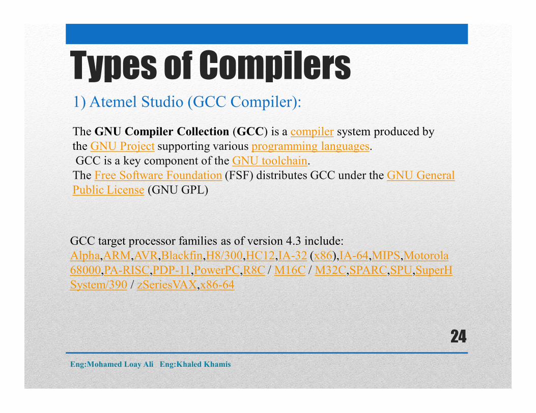
Types of Compilers1) Atemel Studio (GCC Compiler):
The GNU Compiler Collection (GCC) is a compiler system produced by the GNU Project supporting various programming languages.GCC is a key component of the GNU toolchain.
The Free Software Foundation (FSF) distributes GCC under the GNU General Public License (GNU GPL)
GCC target processor families as of version 4.3 include:Alpha,ARM,AVR,Blackfin,H8/300,HC12,IA-32 (x86),IA-64,MIPS,Motorola 68000,PA-RISC,PDP-11,PowerPC,R8C / M16C / M32C,SPARC,SPU,SuperHSystem/390 / zSeriesVAX,x86-64
Eng:Mohamed Loay Ali Eng:Khaled Khamis
24
Types of Compilers2)CodeVision:
Is the only integrated development environment on the market that features an automatic program generator for AVR Family.
It targets only the AVR Processor.
Eng:Mohamed Loay Ali Eng:Khaled Khamis
25
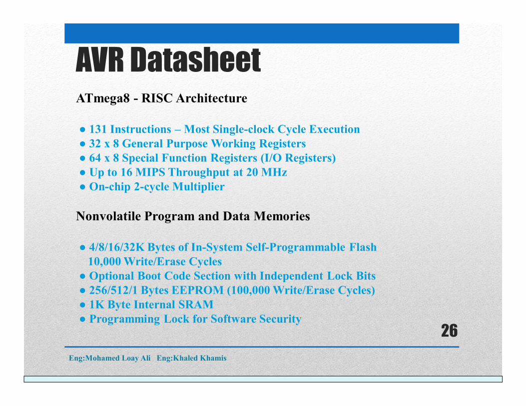
ATmega8 - RISC Architecture
● 131 Instructions – Most Single-clock Cycle Execution● 32 x 8 General Purpose Working Registers● 64 x 8 Special Function Registers (I/O Registers)● Up to 16 MIPS Throughput at 20 MHz● On-chip 2-cycle Multiplier
Nonvolatile Program and Data Memories
● 4/8/16/32K Bytes of In-System Self-Programmable Flash 10,000 Write/Erase Cycles
● Optional Boot Code Section with Independent Lock Bits● 256/512/1 Bytes EEPROM (100,000 Write/Erase Cycles)● 1K Byte Internal SRAM● Programming Lock for Software Security
AVR Datasheet
Eng:Mohamed Loay Ali Eng:Khaled Khamis
26
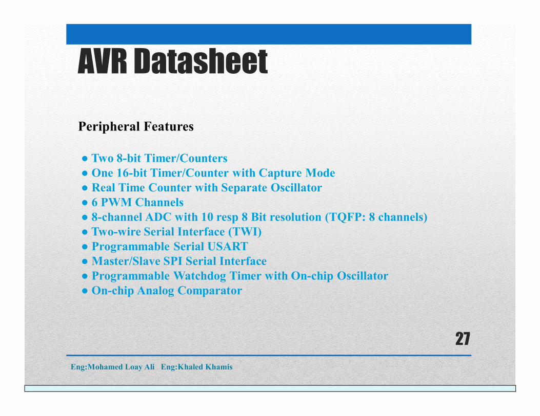
Peripheral Features
● Two 8-bit Timer/Counters● One 16-bit Timer/Counter with Capture Mode● Real Time Counter with Separate Oscillator● 6 PWM Channels● 8-channel ADC with 10 resp 8 Bit resolution (TQFP: 8 channels)● Two-wire Serial Interface (TWI)● Programmable Serial USART● Master/Slave SPI Serial Interface● Programmable Watchdog Timer with On-chip Oscillator● On-chip Analog Comparator
AVR Datasheet
Eng:Mohamed Loay Ali Eng:Khaled Khamis
27
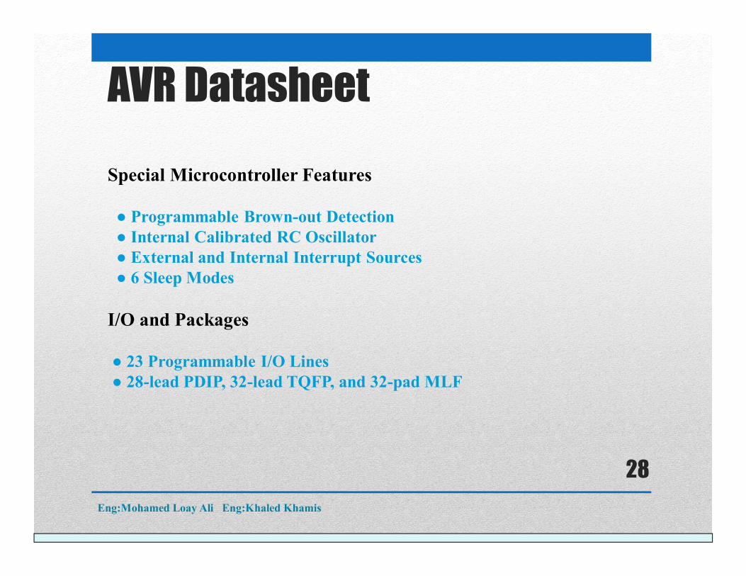
Special Microcontroller Features
● Programmable Brown-out Detection● Internal Calibrated RC Oscillator● External and Internal Interrupt Sources● 6 Sleep Modes
I/O and Packages
● 23 Programmable I/O Lines● 28-lead PDIP, 32-lead TQFP, and 32-pad MLF
AVR Datasheet
Eng:Mohamed Loay Ali Eng:Khaled Khamis
28
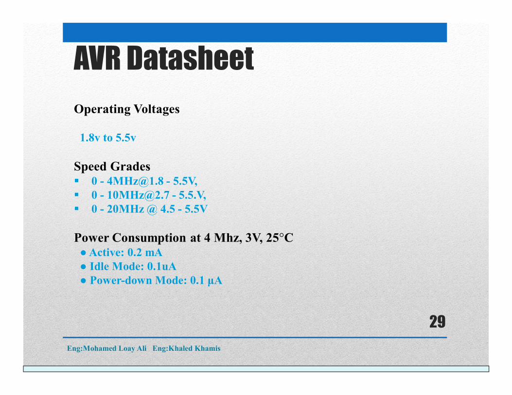
Operating Voltages
1.8v to 5.5v
Speed Grades 0 - [email protected] - 5.5V, 0 - [email protected] - 5.5.V, 0 - 20MHz @ 4.5 - 5.5V
Power Consumption at 4 Mhz, 3V, 25°C● Active: 0.2 mA● Idle Mode: 0.1uA● Power-down Mode: 0.1 μA
AVR Datasheet
Eng:Mohamed Loay Ali Eng:Khaled Khamis
29
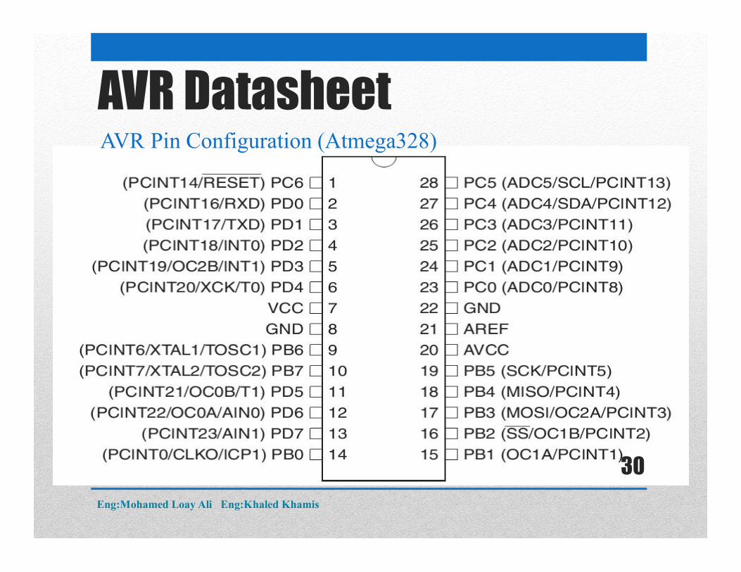
AVR Pin Configuration (Atmega328)
AVR Datasheet
Eng:Mohamed Loay Ali Eng:Khaled Khamis
30
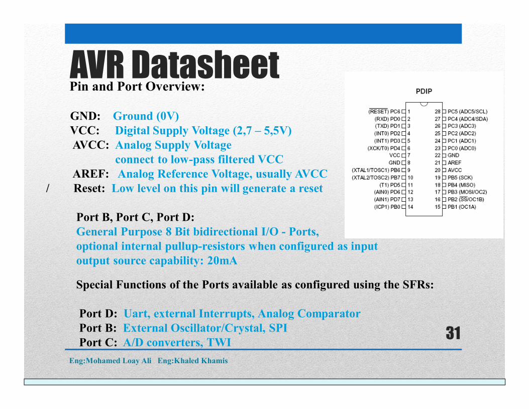
Pin and Port Overview:
GND: Ground (0V)VCC: Digital Supply Voltage (2,7 – 5,5V)AVCC: Analog Supply Voltage
connect to low-pass filtered VCCAREF: Analog Reference Voltage, usually AVCC
/ Reset: Low level on this pin will generate a reset
Port B, Port C, Port D: General Purpose 8 Bit bidirectional I/O - Ports, optional internal pullup-resistors when configured as inputoutput source capability: 20mA
Special Functions of the Ports available as configured using the SFRs:
Port D: Uart, external Interrupts, Analog ComparatorPort B: External Oscillator/Crystal, SPIPort C: A/D converters, TWI
AVR Datasheet
Eng:Mohamed Loay Ali Eng:Khaled Khamis
31
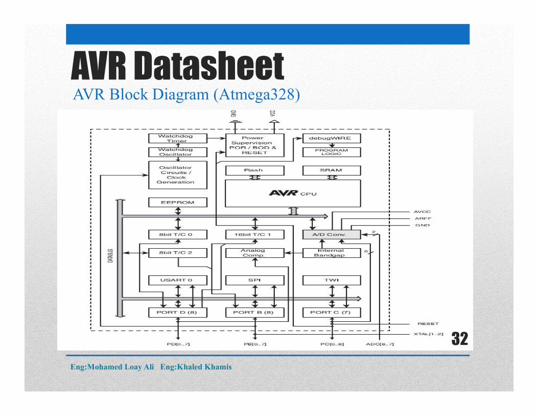
AVR Block Diagram (Atmega328)AVR Datasheet
Eng:Mohamed Loay Ali Eng:Khaled Khamis
32
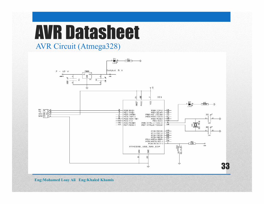
AVR DatasheetAVR Circuit (Atmega328)
Eng:Mohamed Loay Ali Eng:Khaled Khamis
33
AVR DatasheetAVR Circuit Components (Atmega328)
1) Atemga328.2) Crystal Oscillator 16 MHz3) 2 Capacitor 22 pf.4) 10 Kilo ohm Resistor.5) Press Switch.6) Power Supply 5V
Eng:Mohamed Loay Ali Eng:Khaled Khamis
34
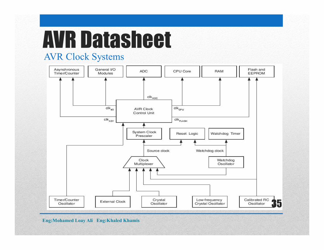
AVR DatasheetAVR Clock Systems
Eng:Mohamed Loay Ali Eng:Khaled Khamis
35
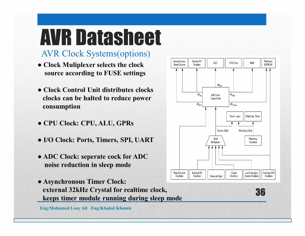
● Clock Muliplexer selects the clock source according to FUSE settings
● Clock Control Unit distributes clocksclocks can be halted to reduce powerconsumption
● CPU Clock: CPU, ALU, GPRs
● I/O Clock: Ports, Timers, SPI, UART
●ADC Clock: seperate cock for ADC noise reduction in sleep mode
●Asynchronous Timer Clock: external 32kHz Crystal for realtime clock, keeps timer module running during sleep mode
AVR DatasheetAVR Clock Systems(options)
Eng:Mohamed Loay Ali Eng:Khaled Khamis
36
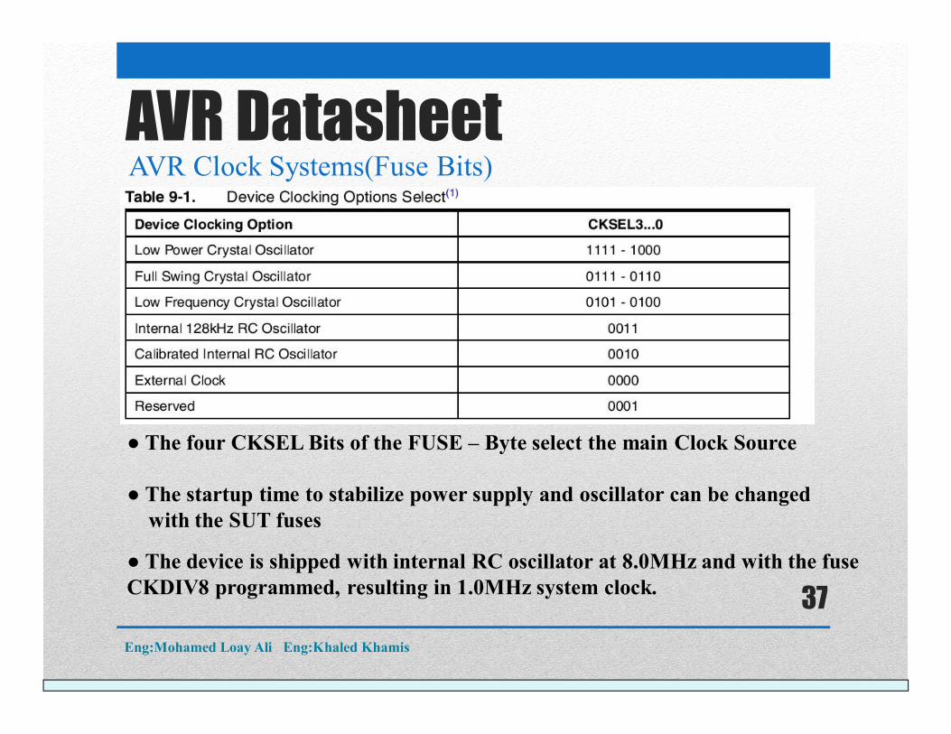
● The four CKSEL Bits of the FUSE – Byte select the main Clock Source
● The startup time to stabilize power supply and oscillator can be changed with the SUT fuses
● The device is shipped with internal RC oscillator at 8.0MHz and with the fuse CKDIV8 programmed, resulting in 1.0MHz system clock.
AVR DatasheetAVR Clock Systems(Fuse Bits)
Eng:Mohamed Loay Ali Eng:Khaled Khamis
37
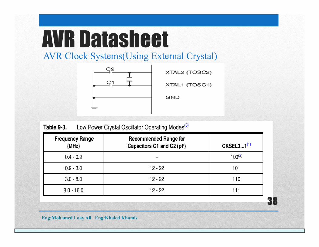
AVR DatasheetAVR Clock Systems(Using External Crystal)
Eng:Mohamed Loay Ali Eng:Khaled Khamis
38
AVR Input/ Output Configuration
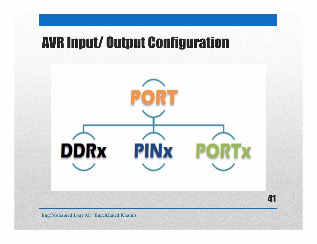
The following registers are related to the various port operations that we can perform with the GPIO pins.1) DDRx – Data Direction Register2) PORTx – Pin Output Register3) PINx – Pin Input Registerwhere x = GPIO port name (A, B, C or D)
Eng:Mohamed Loay Ali Eng:Khaled Khamis
39
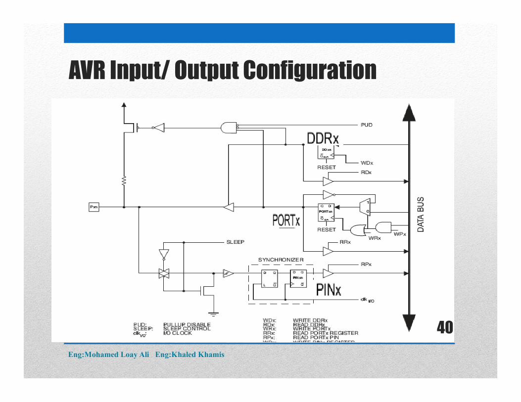
AVR Input/ Output Configuration
Eng:Mohamed Loay Ali Eng:Khaled Khamis
40
AVR Input/ Output Configuration
Eng:Mohamed Loay Ali Eng:Khaled Khamis
41
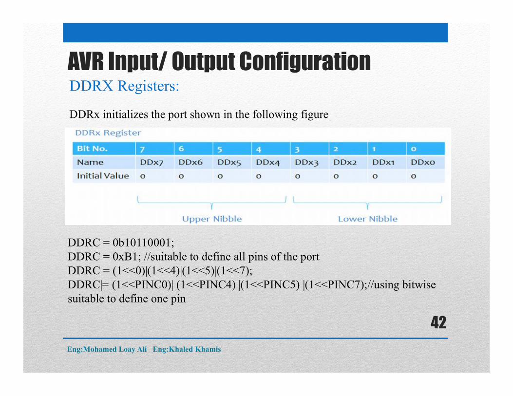
AVR Input/ Output ConfigurationDDRX Registers:
DDRx initializes the port shown in the following figure
DDRC = 0b10110001;DDRC = 0xB1; //suitable to define all pins of the portDDRC = (1<<0)|(1<<4)|(1<<5)|(1<<7);DDRC|= (1<<PINC0)| (1<<PINC4) |(1<<PINC5) |(1<<PINC7);//using bitwise suitable to define one pin
Eng:Mohamed Loay Ali Eng:Khaled Khamis
42
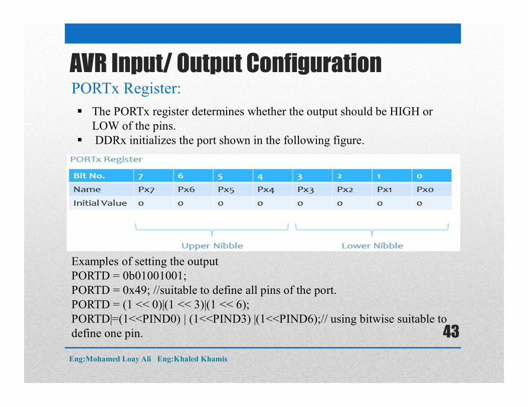
AVR Input/ Output ConfigurationPORTx Register:
The PORTx register determines whether the output should be HIGH or LOW of the pins.
DDRx initializes the port shown in the following figure.
Examples of setting the outputPORTD = 0b01001001;PORTD = 0x49; //suitable to define all pins of the port.PORTD = (1 << 0)|(1 << 3)|(1 << 6);PORTD|=(1<<PIND0) | (1<<PIND3) |(1<<PIND6);// using bitwise suitable to define one pin.
Eng:Mohamed Loay Ali Eng:Khaled Khamis
43
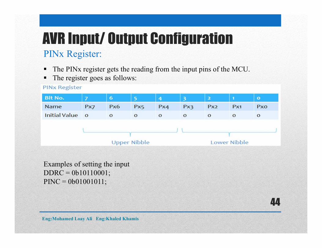
AVR Input/ Output ConfigurationPINx Register:
The PINx register gets the reading from the input pins of the MCU. The register goes as follows:
Examples of setting the inputDDRC = 0b10110001;PINC = 0b01001011;
Eng:Mohamed Loay Ali Eng:Khaled Khamis
44
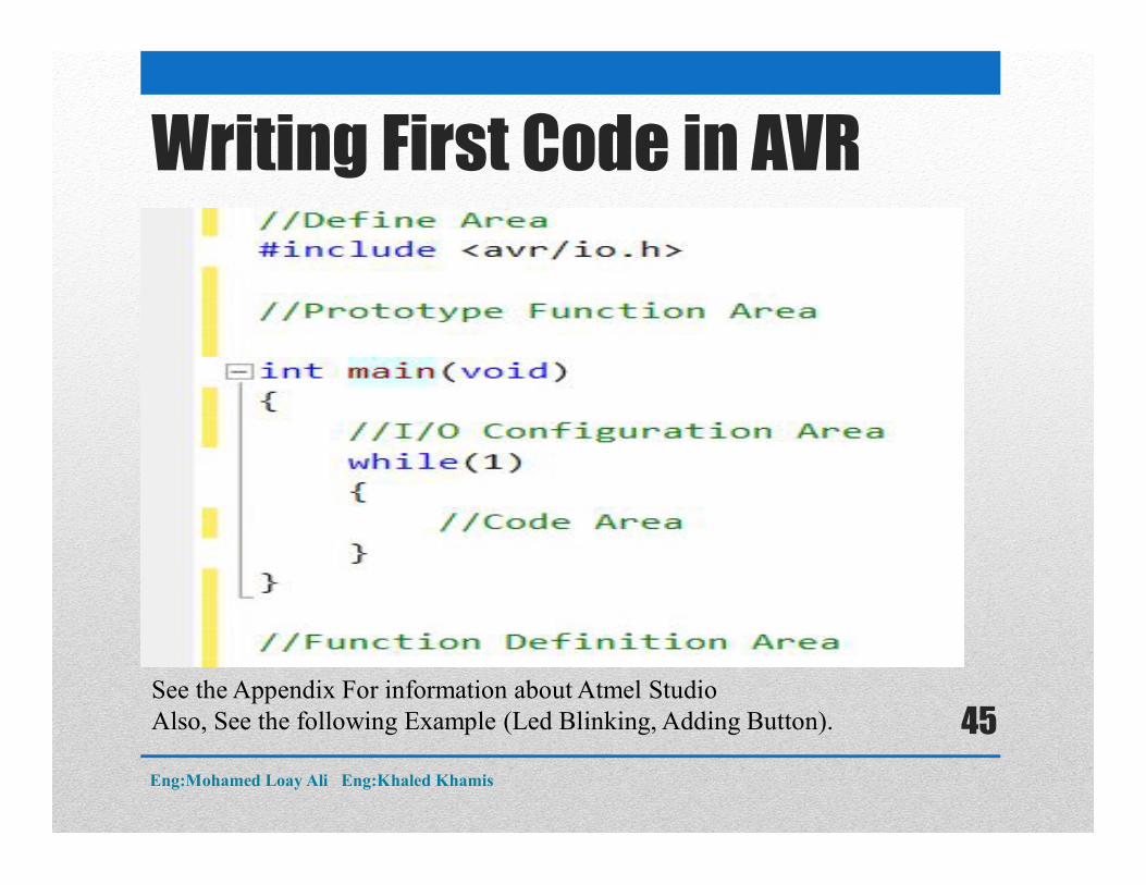
Writing First Code in AVR
See the Appendix For information about Atmel StudioAlso, See the following Example (Led Blinking, Adding Button).
Eng:Mohamed Loay Ali Eng:Khaled Khamis
45
Transfer First Program to AVR
The following programs are used to download the program (Hex file):1. Khazama2. Extreme Burner3. AVR Burn – O - Mat
Transfer the Program to AVR:
Eng:Mohamed Loay Ali Eng:Khaled Khamis
46
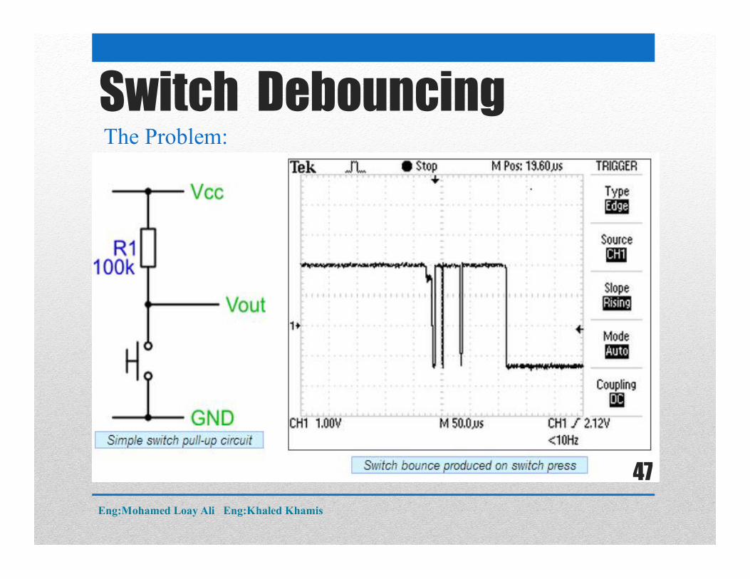
Switch DebouncingThe Problem:
Eng:Mohamed Loay Ali Eng:Khaled Khamis
47
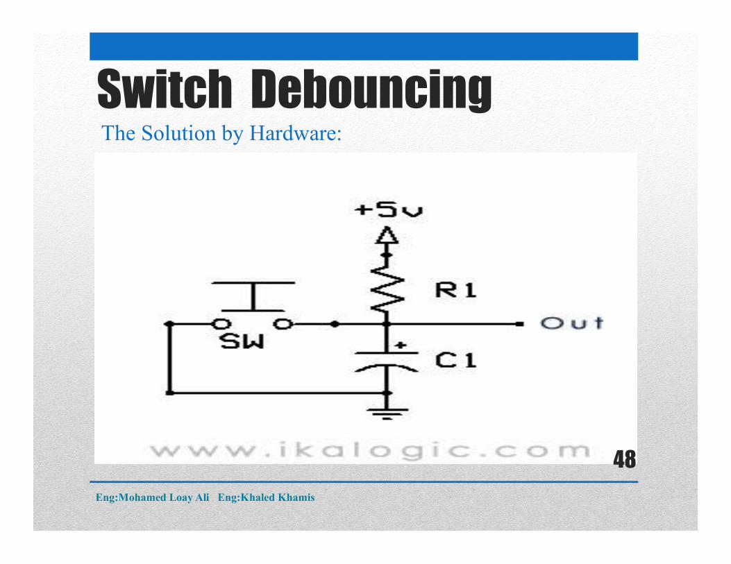
Switch DebouncingThe Solution by Hardware:
Eng:Mohamed Loay Ali Eng:Khaled Khamis
48