Embed Size (px)
Citation preview
Rubber Engine SizingFixed Engine Sizing
Geometry Sizing
Initial Sizing
February 10, 2009
Initial Sizing
Rubber Engine SizingFixed Engine Sizing
Geometry Sizing
Review of sizingRefined Sizing EquationEmpty-Weight FractionFuel WeightSummary of Refined Sizing Method
Outline
1 Rubber Engine SizingReview of sizingRefined Sizing EquationEmpty-Weight FractionFuel WeightSummary of Refined Sizing Method
2 Fixed Engine Sizing
3 Geometry SizingFuselage and WingTail areaControl Surface Sizing
Initial Sizing
Rubber Engine SizingFixed Engine Sizing
Geometry Sizing
Review of sizingRefined Sizing EquationEmpty-Weight FractionFuel WeightSummary of Refined Sizing Method
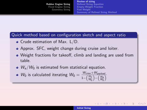
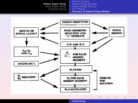
Quick method based on configuration sketch and aspect ratio
Crude estimation of Max. L/D.
Approx. SFC, weight change during cruise and loiter.
Weight fractions for takeoff, climb and landing are used fromtable.
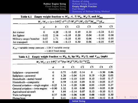
We/W0 is estimated from statistical equation.
W0 is calculated iterating W0 =Wcrew +Wpayload
1−“
WfW0
”−
“WeW0
”
Initial Sizing
Rubber Engine SizingFixed Engine Sizing
Geometry Sizing
Review of sizingRefined Sizing EquationEmpty-Weight FractionFuel WeightSummary of Refined Sizing Method
Outline
1 Rubber Engine SizingReview of sizingRefined Sizing EquationEmpty-Weight FractionFuel WeightSummary of Refined Sizing Method
2 Fixed Engine Sizing
3 Geometry SizingFuselage and WingTail areaControl Surface Sizing
Initial Sizing
Rubber Engine SizingFixed Engine Sizing
Geometry Sizing
Review of sizingRefined Sizing EquationEmpty-Weight FractionFuel WeightSummary of Refined Sizing Method
.
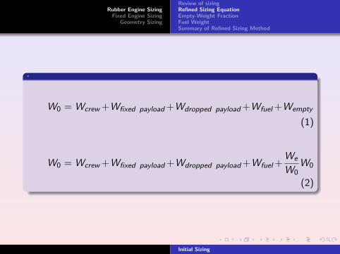
W0 = Wcrew +Wfixed payload +Wdropped payload +Wfuel +Wempty
(1)
W0 = Wcrew +Wfixed payload +Wdropped payload +Wfuel +We
W0W0
(2)
Initial Sizing
Rubber Engine SizingFixed Engine Sizing
Geometry Sizing
Review of sizingRefined Sizing EquationEmpty-Weight FractionFuel WeightSummary of Refined Sizing Method
Outline
1 Rubber Engine SizingReview of sizingRefined Sizing EquationEmpty-Weight FractionFuel WeightSummary of Refined Sizing Method
2 Fixed Engine Sizing
3 Geometry SizingFuselage and WingTail areaControl Surface Sizing
Initial Sizing
Rubber Engine SizingFixed Engine Sizing
Geometry Sizing
Review of sizingRefined Sizing EquationEmpty-Weight FractionFuel WeightSummary of Refined Sizing Method
Initial Sizing
Rubber Engine SizingFixed Engine Sizing
Geometry Sizing
Review of sizingRefined Sizing EquationEmpty-Weight FractionFuel WeightSummary of Refined Sizing Method
Outline
1 Rubber Engine SizingReview of sizingRefined Sizing EquationEmpty-Weight FractionFuel WeightSummary of Refined Sizing Method
2 Fixed Engine Sizing
3 Geometry SizingFuselage and WingTail areaControl Surface Sizing
Initial Sizing
Rubber Engine SizingFixed Engine Sizing
Geometry Sizing
Review of sizingRefined Sizing EquationEmpty-Weight FractionFuel WeightSummary of Refined Sizing Method
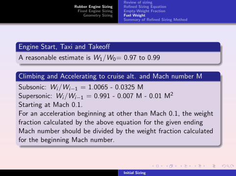
Engine Start, Taxi and Takeoff
A reasonable estimate is W1/W0= 0.97 to 0.99
Climbing and Accelerating to cruise alt. and Mach number M
Subsonic: Wi/Wi−1 = 1.0065 - 0.0325 MSupersonic: Wi/Wi−1 = 0.991 - 0.007 M - 0.01 M2
Starting at Mach 0.1.For an acceleration beginning at other than Mach 0.1, the weightfraction calculated by the above equation for the given endingMach number should be divided by the weight fraction calculatedfor the beginning Mach number.
Initial Sizing
Rubber Engine SizingFixed Engine Sizing
Geometry Sizing
Review of sizingRefined Sizing EquationEmpty-Weight FractionFuel WeightSummary of Refined Sizing Method
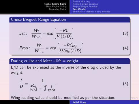
Cruise Breguet Range Equation
Jet :Wi
Wi−1= exp
[−RC
V (L/D)
](3)
Prop :Wi
Wi−1= exp
[−RCbhp
550ηp (L/D)
](4)
During cruise and loiter - lift = weight
L/D can be expressed as the inverse of the drag divided by theweight:
L
D=
1qCd0W /S + W
S1
qπAe
(5)
Wing loading value should be modified as per the situation.Initial Sizing
Rubber Engine SizingFixed Engine Sizing
Geometry Sizing
Review of sizingRefined Sizing EquationEmpty-Weight FractionFuel WeightSummary of Refined Sizing Method
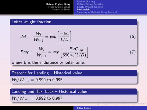
Loiter weight fraction
Jet :Wi
Wi−1= exp
[−EC
L/D
](6)
Prop :Wi
Wi−1= exp
[−EVCbhp
550ηp (L/D)
](7)
where E is the endurance or loiter time.
Descent for Landing – Historical value
Wi/Wi−1 = 0.990 to 0.995
Landing and Taxi back – Historical value
Wi/Wi−1 = 0.992 to 0.997
Initial Sizing
Rubber Engine SizingFixed Engine Sizing
Geometry Sizing
Review of sizingRefined Sizing EquationEmpty-Weight FractionFuel WeightSummary of Refined Sizing Method
Outline
1 Rubber Engine SizingReview of sizingRefined Sizing EquationEmpty-Weight FractionFuel WeightSummary of Refined Sizing Method
2 Fixed Engine Sizing
3 Geometry SizingFuselage and WingTail areaControl Surface Sizing
Initial Sizing
Rubber Engine SizingFixed Engine Sizing
Geometry Sizing
Review of sizingRefined Sizing EquationEmpty-Weight FractionFuel WeightSummary of Refined Sizing Method
Initial Sizing
Rubber Engine SizingFixed Engine Sizing
Geometry Sizing
Outline
1 Rubber Engine SizingReview of sizingRefined Sizing EquationEmpty-Weight FractionFuel WeightSummary of Refined Sizing Method
2 Fixed Engine Sizing
3 Geometry SizingFuselage and WingTail areaControl Surface Sizing
Initial Sizing
Rubber Engine SizingFixed Engine Sizing
Geometry Sizing
.
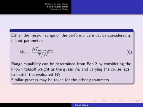
Either the mission range or the performance must be considered afallout parameter.
W0 =NTper engine
T/W(8)
Range capability can be determined from Eqn.2 by considering theknown takeoff weight as the guess W0 and varying the cruise legsto match the evaluated W0.Similar process may be taken for the other parameters.
Initial Sizing
Rubber Engine SizingFixed Engine Sizing
Geometry Sizing
Fuselage and WingTail areaControl Surface Sizing
Outline
1 Rubber Engine SizingReview of sizingRefined Sizing EquationEmpty-Weight FractionFuel WeightSummary of Refined Sizing Method
2 Fixed Engine Sizing
3 Geometry SizingFuselage and WingTail areaControl Surface Sizing
Initial Sizing
Rubber Engine SizingFixed Engine Sizing
Geometry Sizing
Fuselage and WingTail areaControl Surface Sizing
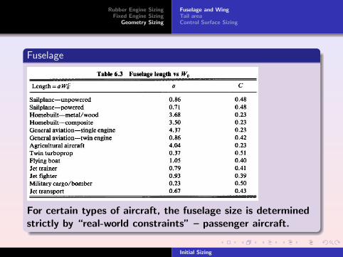
Fuselage
For certain types of aircraft, the fuselage size is determinedstrictly by “real-world constraints” – passenger aircraft.
Initial Sizing
Rubber Engine SizingFixed Engine Sizing
Geometry Sizing
Fuselage and WingTail areaControl Surface Sizing
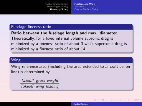
Fuselage fineness ratio
Ratio between the fuselage length and max. diameter.Theoretically, for a fixed internal volume subsonic drag isminimized by a fineness ratio of about 3 while supersonic drag isminimized by a fineness ratio of about 14.
Wing
Wing reference area (including the area extended to aircraft centerline) is determined by
Takeoff gross weight
Takeoff wing loading
Initial Sizing
Rubber Engine SizingFixed Engine Sizing
Geometry Sizing
Fuselage and WingTail areaControl Surface Sizing
Outline
1 Rubber Engine SizingReview of sizingRefined Sizing EquationEmpty-Weight FractionFuel WeightSummary of Refined Sizing Method
2 Fixed Engine Sizing
3 Geometry SizingFuselage and WingTail areaControl Surface Sizing
Initial Sizing
Rubber Engine SizingFixed Engine Sizing
Geometry Sizing
Fuselage and WingTail areaControl Surface Sizing
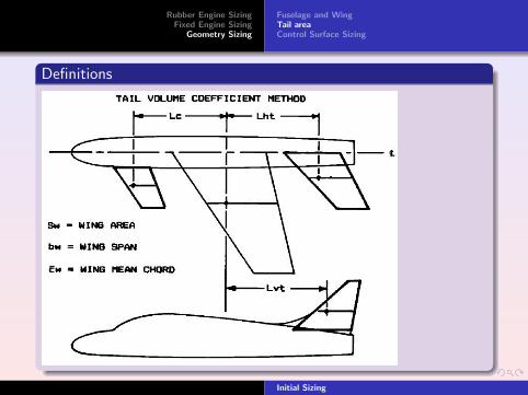
Definitions
Initial Sizing
Rubber Engine SizingFixed Engine Sizing
Geometry Sizing
Fuselage and WingTail areaControl Surface Sizing
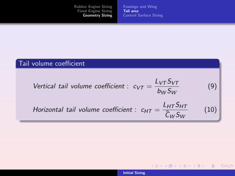
Tail volume coefficient
Vertical tail volume coefficient : cVT =LVT SVT
bW SW(9)
Horizontal tail volume coefficient : cHT =LHT SHT
C̄W SW(10)
Initial Sizing
Rubber Engine SizingFixed Engine Sizing
Geometry Sizing
Fuselage and WingTail areaControl Surface Sizing
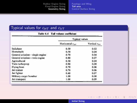
Typical values for cHT and cVT
Initial Sizing

Rubber Engine SizingFixed Engine Sizing
Geometry Sizing
Fuselage and WingTail areaControl Surface Sizing
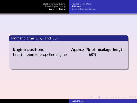
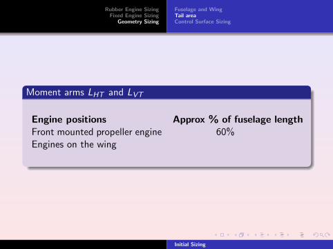
Moment arms LHT and LVT
Engine positions Approx % of fuselage lengthFront mounted propeller engine
60%Engines on the wing 50 – 55 %Aft-mounted engines 45 – 50 %
Initial Sizing
Rubber Engine SizingFixed Engine Sizing
Geometry Sizing
Fuselage and WingTail areaControl Surface Sizing
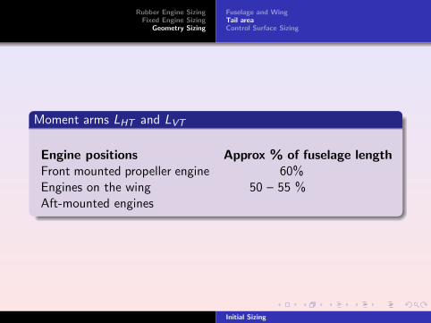
Moment arms LHT and LVT
Engine positions Approx % of fuselage lengthFront mounted propeller engine 60%
Engines on the wing 50 – 55 %Aft-mounted engines 45 – 50 %
Initial Sizing
Rubber Engine SizingFixed Engine Sizing
Geometry Sizing
Fuselage and WingTail areaControl Surface Sizing
Moment arms LHT and LVT
Engine positions Approx % of fuselage lengthFront mounted propeller engine 60%Engines on the wing
50 – 55 %Aft-mounted engines 45 – 50 %
Initial Sizing

Rubber Engine SizingFixed Engine Sizing
Geometry Sizing
Fuselage and WingTail areaControl Surface Sizing
Moment arms LHT and LVT
Engine positions Approx % of fuselage lengthFront mounted propeller engine 60%Engines on the wing 50 – 55 %
Aft-mounted engines 45 – 50 %
Initial Sizing
Rubber Engine SizingFixed Engine Sizing
Geometry Sizing
Fuselage and WingTail areaControl Surface Sizing
Moment arms LHT and LVT
Engine positions Approx % of fuselage lengthFront mounted propeller engine 60%Engines on the wing 50 – 55 %Aft-mounted engines
45 – 50 %
Initial Sizing
Rubber Engine SizingFixed Engine Sizing
Geometry Sizing
Fuselage and WingTail areaControl Surface Sizing
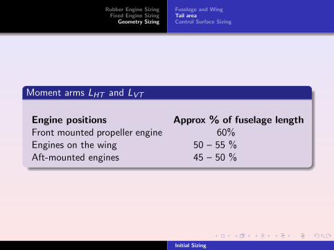
Moment arms LHT and LVT
Engine positions Approx % of fuselage lengthFront mounted propeller engine 60%Engines on the wing 50 – 55 %Aft-mounted engines 45 – 50 %
Initial Sizing
Rubber Engine SizingFixed Engine Sizing
Geometry Sizing
Fuselage and WingTail areaControl Surface Sizing
Outline
1 Rubber Engine SizingReview of sizingRefined Sizing EquationEmpty-Weight FractionFuel WeightSummary of Refined Sizing Method
2 Fixed Engine Sizing
3 Geometry SizingFuselage and WingTail areaControl Surface Sizing
Initial Sizing
Rubber Engine SizingFixed Engine Sizing
Geometry Sizing
Fuselage and WingTail areaControl Surface Sizing
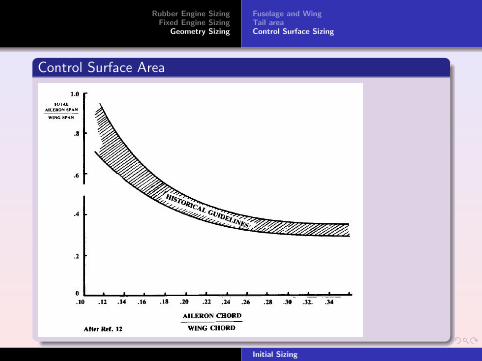
Control Surface Area
Initial Sizing