Embed Size (px)
DESCRIPTION
Nota subjek Applied Thermo
Citation preview
•1/10/2013
•1
GAS TURBINE CYCLES
Introduction
Chapter Objective
• To carry out first law analysis on a gas turbine plant
in which the working fluid is assumed as a perfect
gas.
How a Gas Turbine Works?
• It is a heat engine in which a pressurized hot gas
spins a gas turbine, thus producing mechanical work.
• This pressurized gas produced by burning fuels such
as propane, natural gas, kerosene or jet fuel.
• The heat that comes from burning fuel expands air,
and the high speed rush of this hot air spins the
turbine.•1-Oct-13 •Gas Turbine Cycle •2

•1/10/2013
•2
Gas Turbine Combined Cycle
•1-Oct-13 •Gas Turbine Cycle •3
The Use of Gas Turbine
Gas turbine plants are widely used in the following
engineering fields:
1. Aircraft propulsion system
2. Electric power generation
3. Marine vehicle propulsion
4. Combined-cycle power plant (with steam
power plant)
•1-Oct-13 •Gas Turbine Cycle •4

•1/10/2013
•3
Aircraft engine
•1-Oct-13 •Gas Turbine Cycle •5
Front view of the aircraft engine
Aircraft engine sketch
Gas Turbine Animation
•1-Oct-13 •Gas Turbine Cycle •6
Gas Turbine Animation.mp4
•1/10/2013
•4
Note:
The processes taking place in an actual gas turbine
plant are complicated. To carry out
thermodynamics study on the system, we will
develop a simplified model of the system.
•1-Oct-13 •Gas Turbine Cycle •7
Types of Gas Turbine Cycles
There are two types of gas turbine cycle: Brayton/Joule Cycle
and Atkinson Cycle.
Brayton Cycle
Heat added and rejected is at constant pressure.
Atkinson Cycle
1. Heat added at constant volume, therefore
a. It needs valve to control gas flow to ascertain constant volume
b. Complicated
2. Heat rejected at constant pressure
3. Not popular
4. Out of the SKMM2423 scope.
•1-Oct-13 •Gas Turbine Cycle •8
•1/10/2013
•5
Brayton Cycle
• It is an ideal and closed type cycle.
• It is used as a reference cycle, where actual
cycle can be compared with this cycle.
• The working fluid is merely air.
• The basic components comprise of air
compressor, heat exchanger and gas turbine.
•1-Oct-13 •Gas Turbine Cycle•9
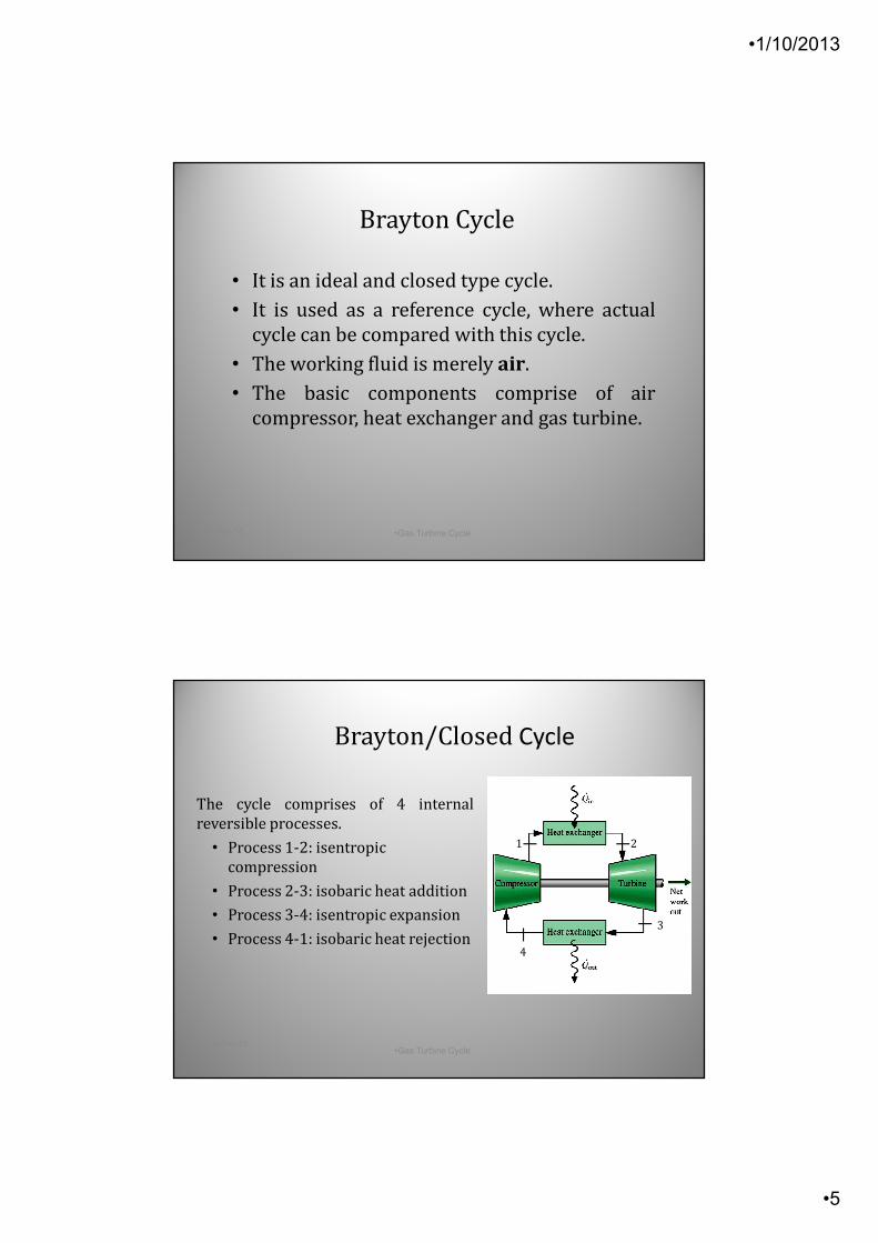
Brayton/Closed Cycle
The cycle comprises of 4 internal
reversible processes.
• Process 1-2: isentropic
compression
• Process 2-3: isobaric heat addition
• Process 3-4: isentropic expansion
• Process 4-1: isobaric heat rejection
•1-Oct-13•Gas Turbine Cycle
•10
1
3
4
2
•1/10/2013
•6
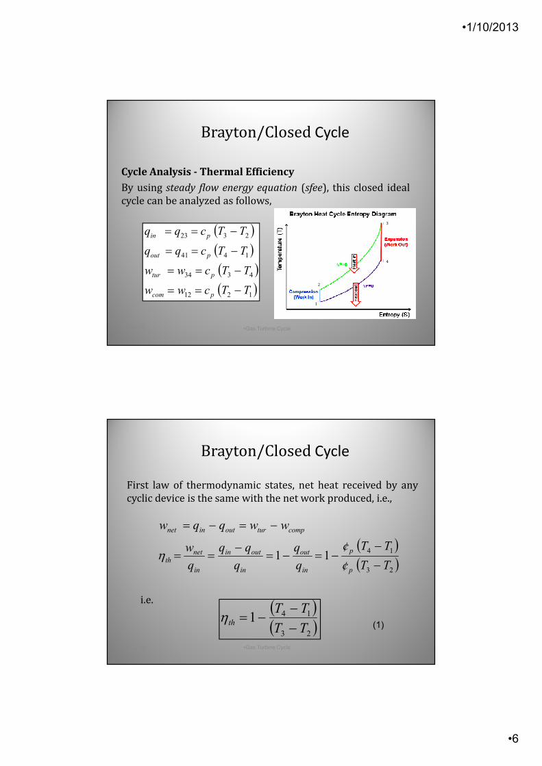
Cycle Analysis - Thermal Efficiency
By using steady flow energy equation (sfee), this closed ideal
cycle can be analyzed as follows,
( )( )( )( )1212
4334
1441
2323
TTcww
TTcww
TTcqq
TTcqq
pcom
ptur
pout
pin
−==
−==
−==
−==
•1-Oct-13 •Gas Turbine Cycle•11
Brayton/Closed Cycle
2
4
1
3
i.e.
( )( )23
1411
TTc
TTc
q
q
q
q
w
wwqqw
p
p
in
out
in
outin
in
netth
compturoutinnet
−/
−/−=−=
−==
−=−=
η
•1-Oct-13 •Gas Turbine Cycle•12
( )( )23
141TT
TTth −
−−=η
(1)
First law of thermodynamic states, net heat received by any
cyclic device is the same with the net work produced, i.e.,
Brayton/Closed Cycle
•1/10/2013
•7
γγ 1
4
3
4
3
−
=p
p
T
T
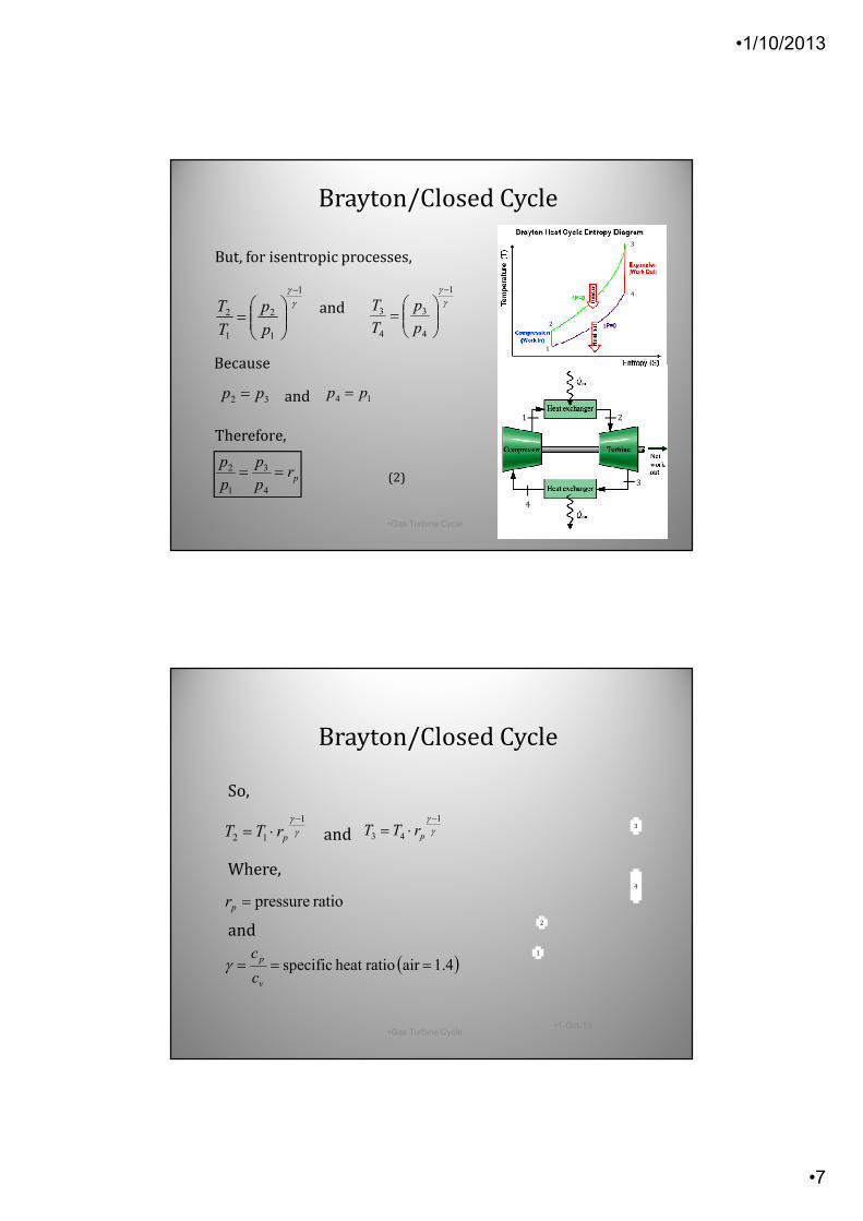
32 pp = 14 pp =
•1-Oct-13 •Gas Turbine Cycle•13
γγ 1
1
2
1
2
−
=p
p
T
T
But, for isentropic processes,
and
Because
and
Therefore,
prp
p
p
p==
4
3
1
2
(2)
1
3
4
2
Brayton/Closed Cycle
2
4
1
3
ratio pressure=pr
( )4.1air ratioheat specific ===v
p
c
cγ
γγ 1
43
−
⋅= prTT
•1-Oct-13•Gas Turbine Cycle
•14
Where,
So,
and
andγγ 1
12
−
⋅= prTT
2
4
1
3
Brayton/Closed Cycle
•1/10/2013
•8
•1-Oct-13•Gas Turbine Cycle
•15
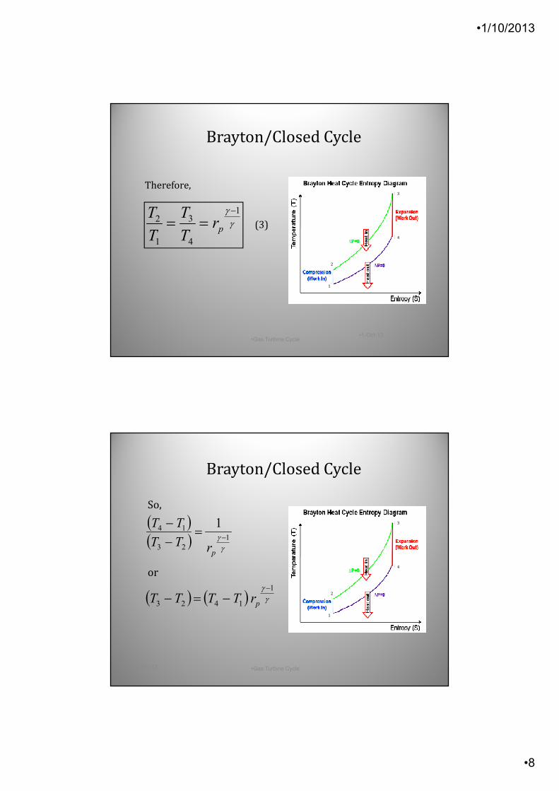
Therefore,
(3)γγ 1
4
3
1
2−
== prT
T
T
T
2
4
1
3
Brayton/Closed Cycle
( ) ( ) γγ 1
1423
−
−=− prTTTT
•1-Oct-13 •Gas Turbine Cycle•16
So,
or
( )( )
γγ 1
23
14 1−=
−−
prTT
TT
Brayton/Closed Cycle
2
4
1
3

•1/10/2013
•9
( )( )
γγη1
23
14 111 −−=
−−
−=
p
th
rTT
TT
•1-Oct-13 •Gas Turbine Cycle•17
So,
(4)
Brayton/Closed Cycle
2
11T
Tth −=η
( )( ) 2
1
2
32
1
41
23
14
1
1
T
T
T
TT
T
TT
TT
TT=
−
−
=−−
•1-Oct-13•Gas Turbine Cycle
•18
Also,
Therefore,
(5)
Note: Only valid for ideal closed cycle.
Brayton/Closed Cycle
•1/10/2013
•10
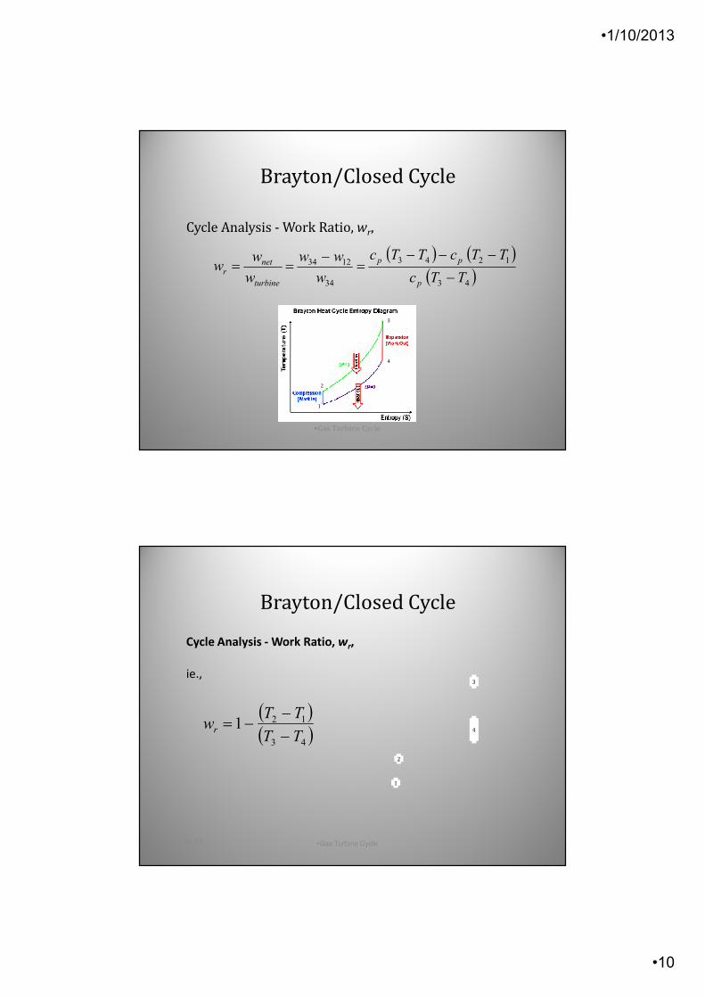
( ) ( )( )43
1243
34
1234
TTc
TTcTTc
w
ww
w
ww
p
pp
turbine
netr −
−−−=
−==
•1-Oct-13 •Gas Turbine Cycle•19
Cycle Analysis - Work Ratio, wr,
Brayton/Closed Cycle
2
4
1
3
( )( )43
121TT
TTwr −
−−=
•1-Oct-13 •Gas Turbine Cycle•20
Cycle Analysis - Work Ratio, wr,
ie.,
Brayton/Closed Cycle
2
4
1
3
•1/10/2013
•11
−
−
−=
−
−
−=−
−−
−
−
1
.1
1
11
1
11
3
11
1
13
1
1
γγ
γγ
γγ
γγ
γγ
p
pp
p
p
r
rT
rrT
r
T
rT
w
γγ 1
12 .−
= prTT
•1-Oct-13•Gas Turbine Cycle
•21
We know that,
andγγ 1
34 −=
pr
TT
Therefore,
Brayton/Closed Cycle
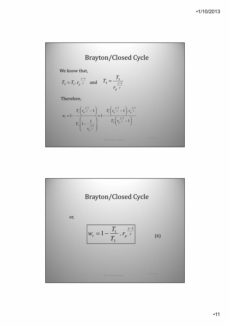
γγ 1
3
1 .1−
−= pr rT
Tw
•1-Oct-13•Gas Turbine Cycle
•22
or,
(6)
Brayton/Closed Cycle
•1/10/2013
•12
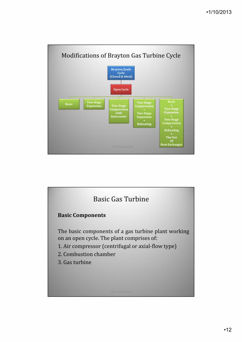
Modifications of Brayton Gas Turbine Cycle
Brayton/Joule
Cycle
(Closed & Ideal)
Open Cycle
BasicTwo-Stage
Expansion Two-Stage
Compression
with
Intercooler
Two-Stage
Compression
+
Two-Stage
Expansion
+
Reheating
Basic
+
Two-Stage
Expansion
+
Two-Stage
Compression
+
Reheating
+
The Use
Of
Heat Exchanger•1-Oct-13 •Gas Turbine Cycle
•23
Basic Gas Turbine
•1-Oct-13 •Gas Turbine Cycle •24
Basic Components
The basic components of a gas turbine plant working
on an open cycle. The plant comprises of:
1. Air compressor (centrifugal or axial-flow type)
2. Combustion chamber
3. Gas turbine

•1/10/2013
•13
•1-Oct-13 •Gas Turbine Cycle •25
Basic Gas Turbine
p2
2’
’
Basic Gas Turbine
•1-Oct-13 •Gas Turbine Cycle •26
Process Description
1-2: Compression process
Atmospheric air at pressure p1 and
temperature T1 is induced and
compressed adiabatically to higher
pressure p2 and temperature T2. The
process is not reversible, thus, not
isentropic.
2-3: Combustion process
Fuel is injected into the air stream. The mixture of air and fuel
is burned at constant pressure inside a combustion chamber
(CC), thus producing hot combustion gases.
p2
2’
’

•1/10/2013
•14
•1-Oct-13 •Gas Turbine Cycle •27
Process Description
3-4: Expansion process
The hot combustion gases expands
through the gas turbine. The
process is assumed adiabatic but
not reversible, thus, not isentropic.
Mechanical work is produced by the
turbine. Part of this work is used to
drive the compressor.
The air exiting the turbine is exhausted to atmosphere. New
fresh air is induced into the compressor and the processes are
repeated.
p2
2 ’
’
Basic Gas Turbine
•1-Oct-13 •Gas Turbine Cycle •28
Energy Analysis
• The steady-flow energy equation
(SFEE) is applied to each
component of the gas turbine
plant.
• Neglecting the change in the
kinetic and potential energy of
the working fluid, we have, work
to drive the compressor:
(7)
p2
2’
’
Basic Gas Turbine
( )' 12.C paw c T T= −
•1/10/2013
•15
•1-Oct-13 •Gas Turbine Cycle•29
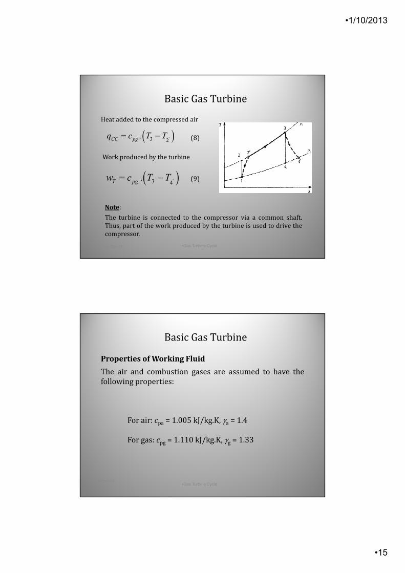
Heat added to the compressed air
(8)
Work produced by the turbine
(9)
Note:
The turbine is connected to the compressor via a common shaft.
Thus, part of the work produced by the turbine is used to drive the
compressor.
p2
2 ’
’
Basic Gas Turbine
( )'3 2.CC pgq c T T= −
( )'3 4.T pgw c T T= −
•1-Oct-13•Gas Turbine Cycle
•30
Properties of Working Fluid
The air and combustion gases are assumed to have the
following properties:
For air: cpa = 1.005 kJ/kg.K, γa = 1.4
For gas: cpg = 1.110 kJ/kg.K, γg = 1.33
Basic Gas Turbine
•1/10/2013
•16
•1-Oct-13 •Gas Turbine Cycle•31
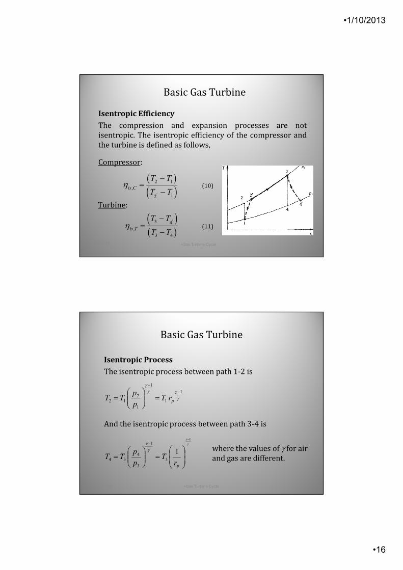
Isentropic Efficiency
The compression and expansion processes are not
isentropic. The isentropic efficiency of the compressor and
the turbine is defined as follows,
Compressor:
(10)
Turbine:
(11)
p2
2 ’
’
Basic Gas Turbine
( )( )'
2 1
,
12
is C
T T
T Tη
−=
−
( )( )
'3 4
,
3 4
is T
T T
T Tη
−=
−
γγγ
γ1
1
1
1
212
−
−
=
= prT
p
pTT
γγ
γγ
1
13
1
3
434
−
=
=
−
prT
p
pTT
•1-Oct-13 •Gas Turbine Cycle •32
Isentropic Process
The isentropic process between path 1-2 is
And the isentropic process between path 3-4 is
where the values of γ for air
and gas are different.
Basic Gas Turbine
•1/10/2013
•17
•1-Oct-13 •Gas Turbine Cycle•33
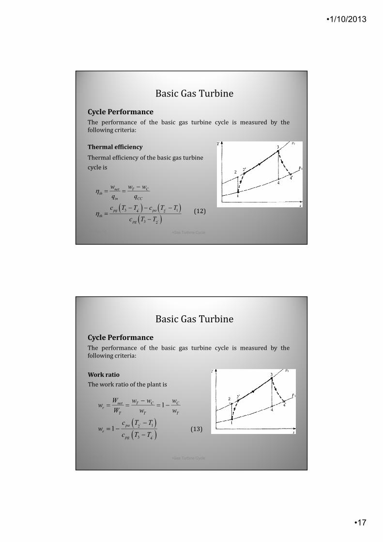
Thermal efficiency
Thermal efficiency of the basic gas turbine
cycle is
Cycle Performance
The performance of the basic gas turbine cycle is measured by the
following criteria:
(12)
p2
2 ’
’
Basic Gas Turbine
( ) ( )( )' '
'
3 14 2
3 2
net T Cth
in CC
pg pa
th
pg
w w w
q q
c T T c T T
c T T
η
η
−= =
− − −=
−
•1-Oct-13 •Gas Turbine Cycle•34
Work ratio
The work ratio of the plant is
(13)
p2
2 ’
’
Cycle Performance
The performance of the basic gas turbine cycle is measured by the
following criteria:
Basic Gas Turbine
( )( )
'
'
12
3 4
1
1
net T C Cr
T T T
pa
r
pg
W w w ww
W w w
c T Tw
c T T
−= = = −
−= −
−
•1/10/2013
•18
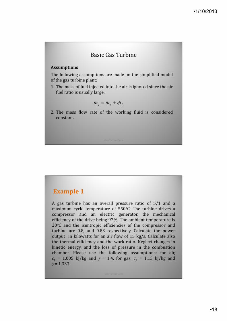
Assumptions
The following assumptions are made on the simplified model
of the gas turbine plant:
1. The mass of fuel injected into the air is ignored since the air
fuel ratio is usually large.
2. The mass flow rate of the working fluid is considered
constant.
fag mmm /+=
•1-Oct-13 •Gas Turbine Cycle •35
Basic Gas Turbine
Example 1
A gas turbine has an overall pressure ratio of 5/1 and a
maximum cycle temperature of 550oC. The turbine drives a
compressor and an electric generator, the mechanical
efficiency of the drive being 97%. The ambient temperature is
20oC and the isentropic efficiencies of the compressor and
turbine are 0.8, and 0.83 respectively. Calculate the power
output in kilowatts for an air flow of 15 kg/s. Calculate also
the thermal efficiency and the work ratio. Neglect changes in
kinetic energy, and the loss of pressure in the combustion
chamber. Please use the following assumptions: for air,
cp = 1.005 kJ/kg and γ = 1.4, for gas, cp = 1.15 kJ/kg and
γ = 1.333.
•1-Oct-13 •Gas Turbine Cycle •36
•1/10/2013
•19
•1-Oct-13 •Gas Turbine Cycle •37
Basic Gas Turbine
p2
2’
’
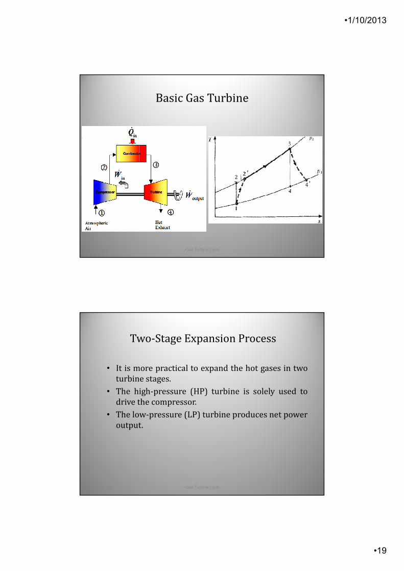
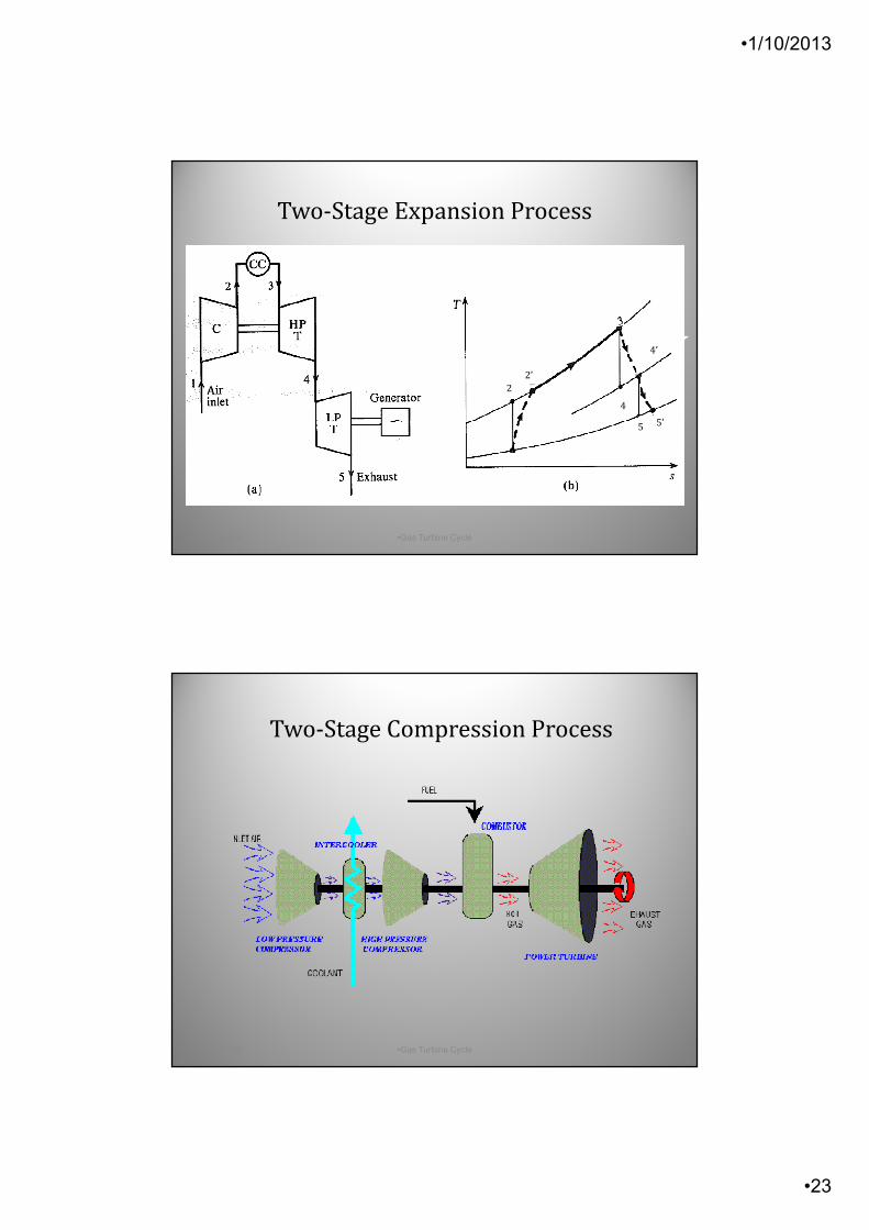
Two-Stage Expansion Process
• It is more practical to expand the hot gases in two
turbine stages.
• The high-pressure (HP) turbine is solely used to
drive the compressor.
• The low-pressure (LP) turbine produces net power
output.
•1-Oct-13 •Gas Turbine Cycle •38
•1/10/2013
•20
•1-Oct-13 •Gas Turbine Cycle •39
Two-Stage Expansion Process
2
2’
4
4’
5 5’
•1-Oct-13 •Gas Turbine Cycle •40
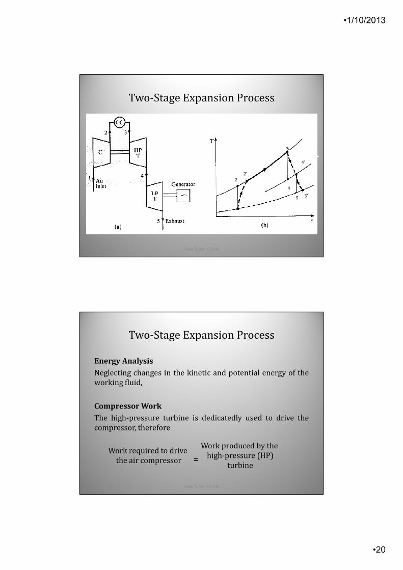
Energy Analysis
Neglecting changes in the kinetic and potential energy of the
working fluid,
Compressor Work
The high-pressure turbine is dedicatedly used to drive the
compressor, therefore
Work required to drive
the air compressor =
Work produced by the
high-pressure (HP)
turbine
Two-Stage Expansion Process
•1/10/2013
•21
•1-Oct-13 •Gas Turbine Cycle •41
Energy Analysis
i.e. wC = wT,hp
or
(14)
where cpa and cpg are specifics heats at constant pressure for
the air and hot gases respectively.
Two-Stage Expansion Process
( ) ( )2' 1 3 4'. .pa pgc T T c T T− = −
•1-Oct-13 •Gas Turbine Cycle •42
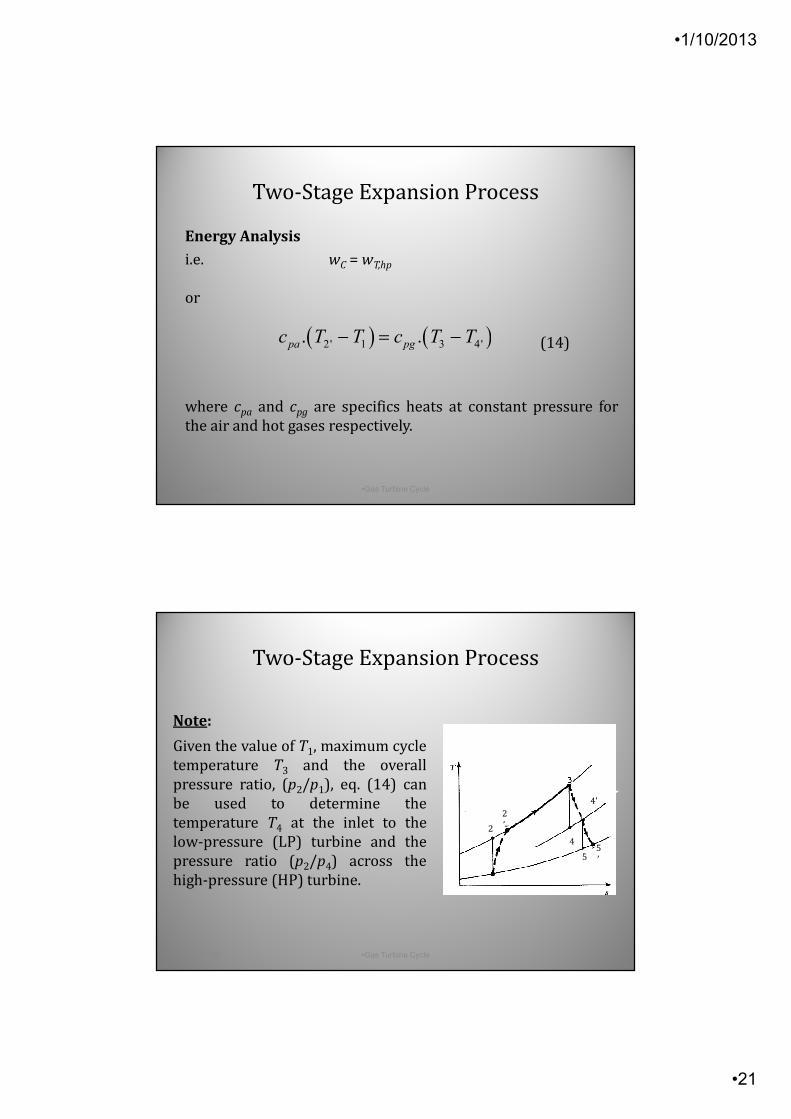
Note:
Given the value of T1, maximum cycle
temperature T3 and the overall
pressure ratio, (p2/p1), eq. (14) can
be used to determine the
temperature T4 at the inlet to the
low-pressure (LP) turbine and the
pressure ratio (p2/p4) across the
high-pressure (HP) turbine.
Two-Stage Expansion Process
2
2
’
4
4’
55
’
•1/10/2013
•22
•1-Oct-13 •Gas Turbine Cycle •43
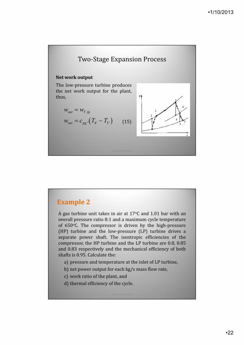
Net work output
The low-pressure turbine produces
the net work output for the plant,
thus,
(15)
Two-Stage Expansion Process
2
2
’
4
4’
55
’( ),
4' 5'.
net T lp
net pg
w w
w c T T
=
= −
A gas turbine unit takes in air at 17oC and 1.01 bar with an
overall pressure ratio 8:1 and a maximum cycle temperature
of 650oC. The compressor is driven by the high-pressure
(HP) turbine and the low-pressure (LP) turbine drives a
separate power shaft. The isentropic efficiencies of the
compressor, the HP turbine and the LP turbine are 0.8, 0.85
and 0.83 respectively and the mechanical efficiency of both
shafts is 0.95. Calculate the:
a) pressure and temperature at the inlet of LP turbine,
b) net power output for each kg/s mass flow rate,
c) work ratio of the plant, and
d) thermal efficiency of the cycle.
•1-Oct-13 •Gas Turbine Cycle •44
Example 2
•1/10/2013
•23
•1-Oct-13 •Gas Turbine Cycle •45
Two-Stage Expansion Process
2
2’
4
4’
5 5’
Two-Stage Compression Process
•1-Oct-13 •Gas Turbine Cycle •46
•1/10/2013
•24
Two-Stage Compression Process
•1-Oct-13 •Gas Turbine Cycle •47
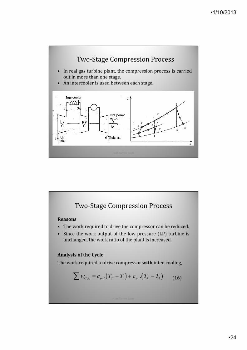
• In real gas turbine plant, the compression process is carried
out in more than one stage.
• An intercooler is used between each stage.
4
4’
A
A’
6’6
2
2’
•1-Oct-13 •Gas Turbine Cycle •48
Reasons
• The work required to drive the compressor can be reduced.
• Since the work output of the low-pressure (LP) turbine is
unchanged, the work ratio of the plant is increased.
Analysis of the Cycle
The work required to drive compressor with inter-cooling,
(16)
Two-Stage Compression Process
( ) ( ), 2 ' 1 4' 3. .C ic pa paw c T T c T T= − + −∑
•1/10/2013
•25
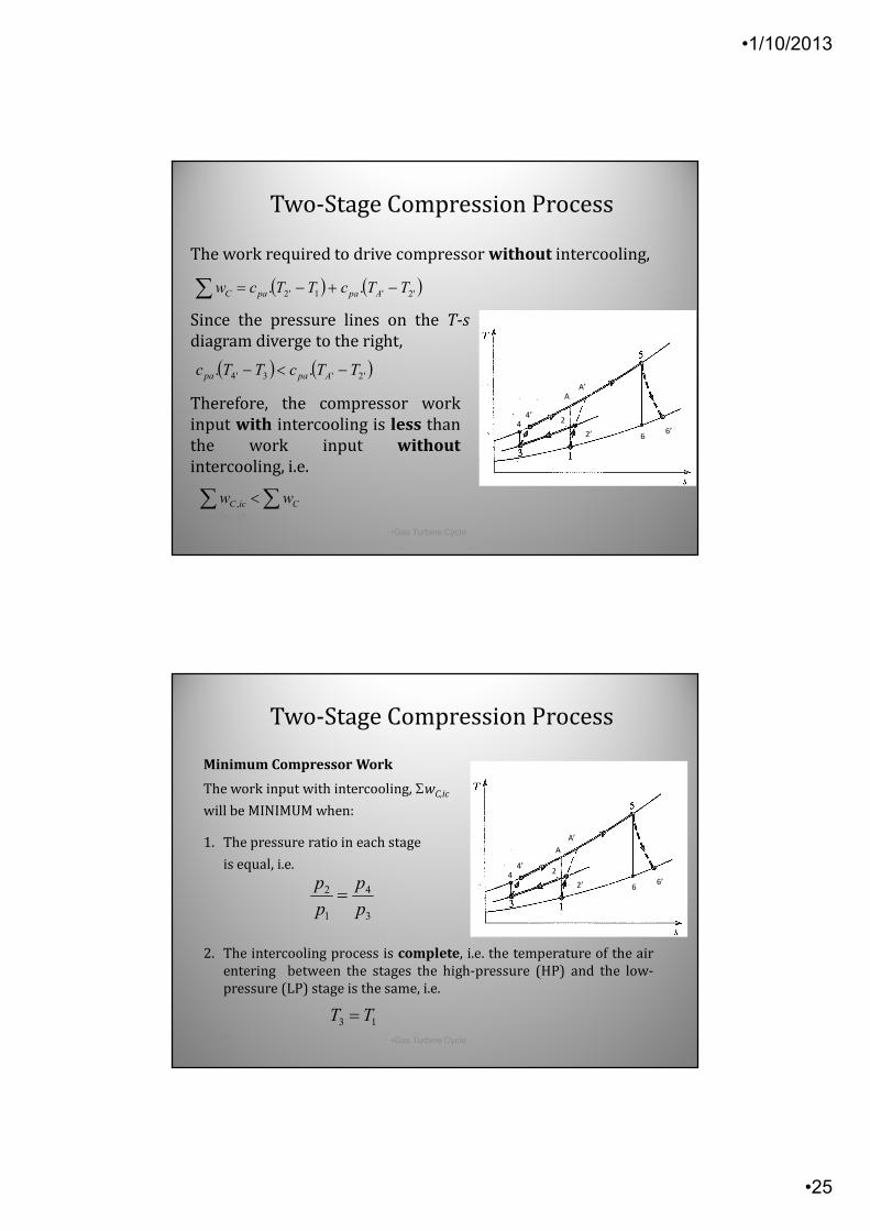
( ) ( )'2'1'2 .. TTcTTcw ApapaC −+−=∑
( ) ( )'2'3'4 .. TTcTTc Apapa −<−
∑ ∑< CicC ww ,
•1-Oct-13
•Gas Turbine Cycle•49
The work required to drive compressor without intercooling,
Since the pressure lines on the T-s
diagram diverge to the right,
Therefore, the compressor work
input with intercooling is less than
the work input without
intercooling, i.e.
Two-Stage Compression Process
44’
AA’
6’6
2
2’
3
4
1
2
p
p
p
p=
13 TT =•1-Oct-13 •Gas Turbine Cycle
•50
Minimum Compressor Work
The work input with intercooling, ΣwC,ic
will be MINIMUM when:
1. The pressure ratio in each stage
is equal, i.e.
2. The intercooling process is complete, i.e. the temperature of the air
entering between the stages the high-pressure (HP) and the low-
pressure (LP) stage is the same, i.e.
Two-Stage Compression Process
44’
A
A’
6’6
2
2’

•1/10/2013
•26
T
CTr
w
www
−=
•1-Oct-13 •Gas Turbine Cycle •51
Advantage
Two-stage compression with inter-
cooling between the stages reduces the
work required to drive the compressor.
Recall,
Since wC is reduced while wT remains
unchanged, the work ratio of the plant
increased.
Two-Stage Compression Process
44’
AA’
6’6
2
2’
( )'45, . TTcq pgicCC −=
( )'5. ApgCC TTcq −=
•1-Oct-13 •Gas Turbine Cycle •52
Disadvantage
The heat added to the air during
combustion with 2-stage compression
and inter-cooling is
and that without 2-stage & inter-cooling
is
From T-s diagram, (T5 – T4’) > (T5 – TA’). Therefore the heat added to the air
increases with 2-stage compression with inter-cooling.
Thus, thermal efficiency of the cycle decreases.
44’
AA’
6’6
2
2’
Two-Stage Compression Process
•1/10/2013
•27
'4'2
31
TT
TT
≠
≠3
4
1
2
p
p
p
p=
3
4
1
2
p
p
p
p≠
•1-Oct-13•Gas Turbine Cycle
•53
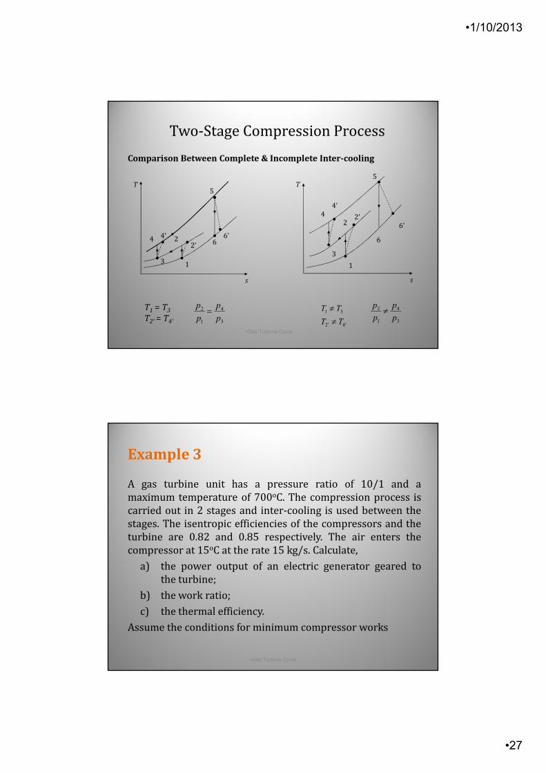
Comparison Between Complete & Incomplete Inter-cooling
T1 = T3
T2’ = T4’
s
T
1
22’
3
4 4’6
5
6’
T
s
1
22’
3
4
4’
6
5
6’
Two-Stage Compression Process
A gas turbine unit has a pressure ratio of 10/1 and a
maximum temperature of 700oC. The compression process is
carried out in 2 stages and inter-cooling is used between the
stages. The isentropic efficiencies of the compressors and the
turbine are 0.82 and 0.85 respectively. The air enters the
compressor at 15oC at the rate 15 kg/s. Calculate,
a) the power output of an electric generator geared to
the turbine;
b) the work ratio;
c) the thermal efficiency.
Assume the conditions for minimum compressor works
•1-Oct-13 •Gas Turbine Cycle •54
Example 3
•1/10/2013
•28
Two-Stage Compression Process
•1-Oct-13 •Gas Turbine Cycle •55
Two-Stage Expansion & Reheating
•1-Oct-13 •Gas Turbine Cycle •56
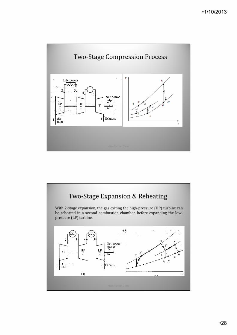
With 2-stage expansion, the gas exiting the high-pressure (HP) turbine can
be reheated in a second combustion chamber, before expanding the low-
pressure (LP) turbine.
22’
4’
4
A A’
6
•1/10/2013
•29
( )''4, . ApgLPt TTcw −=
•1-Oct-13•Gas Turbine Cycle
•57
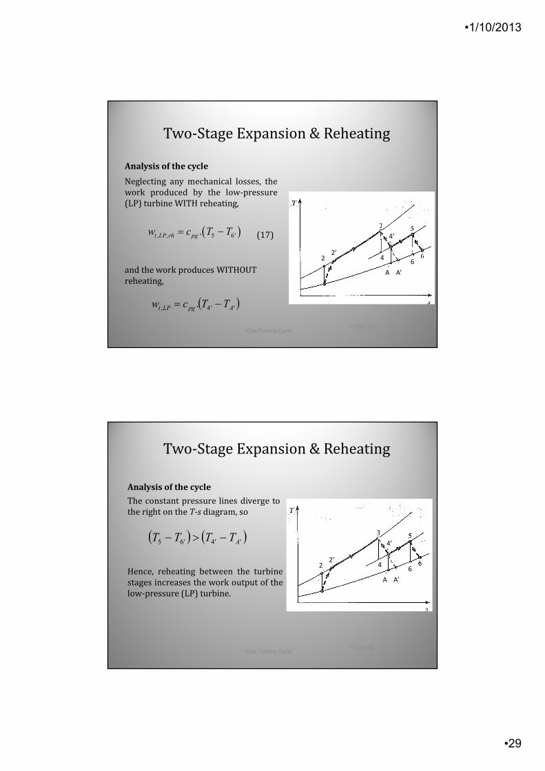
Analysis of the cycle
Neglecting any mechanical losses, the
work produced by the low-pressure
(LP) turbine WITH reheating,
(17)
and the work produces WITHOUT
reheating,
22’
4’
4
A A’
6
Two-Stage Expansion & Reheating
( ), , 5 6'.t LP rh pgw c T T= −
( ) ( )''4'65 ATTTT −>−
•1-Oct-13•Gas Turbine Cycle
•58
Analysis of the cycle
Hence, reheating between the turbine
stages increases the work output of the
low-pressure (LP) turbine.
The constant pressure lines diverge to
the right on the T-s diagram, so
Two-Stage Expansion & Reheating
22’
4’
4
A A’
6
•1/10/2013
•30
∑∑∑ −=
−=
t
c
t
ct
rw
w
w
www 1
•1-Oct-13 •Gas Turbine Cycle •59
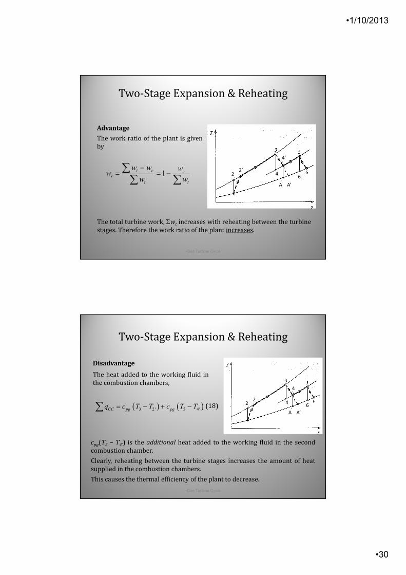
Advantage
The work ratio of the plant is given
by
The total turbine work, Σwt increases with reheating between the turbine
stages. Therefore the work ratio of the plant increases.
Two-Stage Expansion & Reheating
22’
4’
4
A A’
6
•1-Oct-13 •Gas Turbine Cycle •60
cpg(T5 – T4’) is the additional heat added to the working fluid in the second
combustion chamber.
Clearly, reheating between the turbine stages increases the amount of heat
supplied in the combustion chambers.
This causes the thermal efficiency of the plant to decrease.
Disadvantage
The heat added to the working fluid in
the combustion chambers,
(18)
Two-Stage Expansion & Reheating
22
’
4
’
4
A A’
6( ) ( )3 2' 5 4'CC pg pgq c T T c T T= − + −∑
•1/10/2013
•31
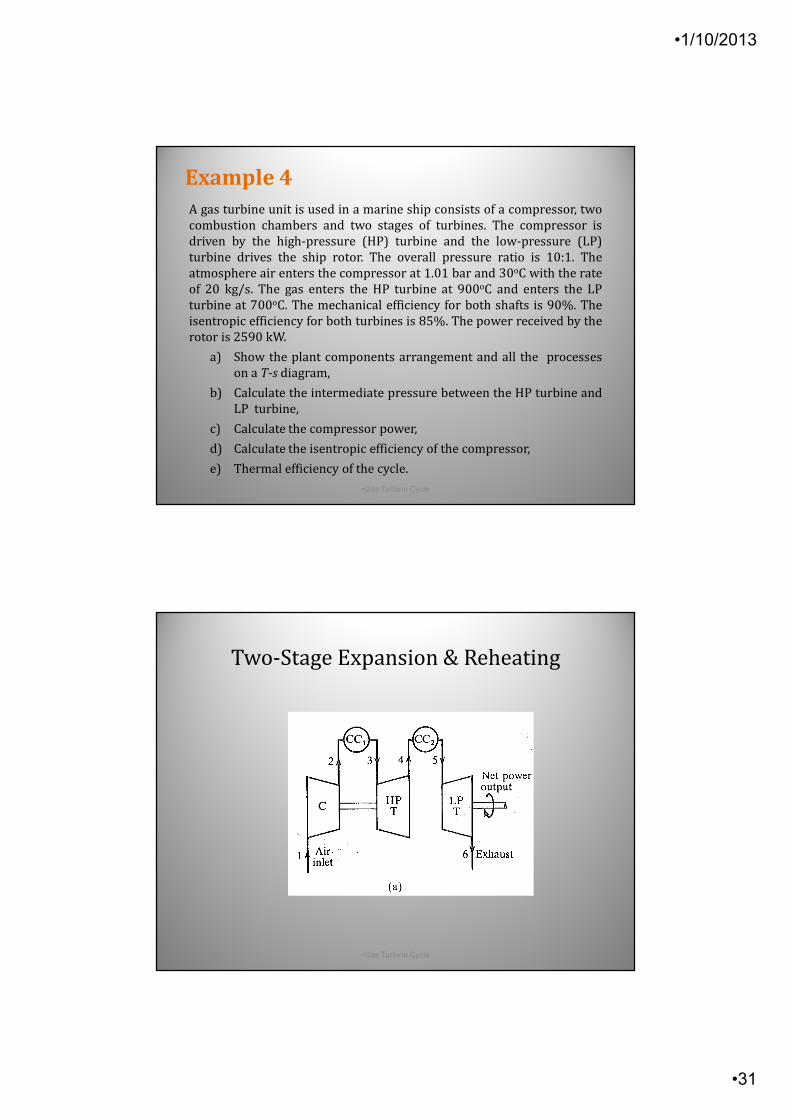
A gas turbine unit is used in a marine ship consists of a compressor, two
combustion chambers and two stages of turbines. The compressor is
driven by the high-pressure (HP) turbine and the low-pressure (LP)
turbine drives the ship rotor. The overall pressure ratio is 10:1. The
atmosphere air enters the compressor at 1.01 bar and 30oC with the rate
of 20 kg/s. The gas enters the HP turbine at 900oC and enters the LP
turbine at 700oC. The mechanical efficiency for both shafts is 90%. The
isentropic efficiency for both turbines is 85%. The power received by the
rotor is 2590 kW.
a) Show the plant components arrangement and all the processes
on a T-s diagram,
b) Calculate the intermediate pressure between the HP turbine and
LP turbine,
c) Calculate the compressor power,
d) Calculate the isentropic efficiency of the compressor,
e) Thermal efficiency of the cycle.
•1-Oct-13 •Gas Turbine Cycle •61
Example 4
•1-Oct-13 •Gas Turbine Cycle •62
Two-Stage Expansion & Reheating
•1/10/2013
•32
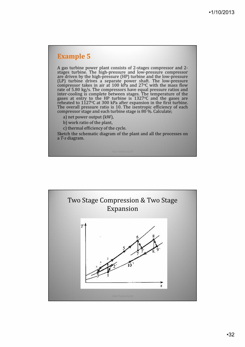
A gas turbine power plant consists of 2-stages compressor and 2-stages turbine. The high-pressure and low-pressure compressorare driven by the high-pressure (HP) turbine and the low-pressure(LP) turbine drives a separate power shaft. The low-pressurecompressor takes in air at 100 kPa and 27oC with the mass flowrate of 5.80 kg/s. The compressors have equal pressure ratios andinter-cooling is complete between stages. The temperature of thegases at entry to the HP turbine is 1327oC and the gases arereheated to 1127oC at 300 kPa after expansion in the first turbine.The overall pressure ratio is 10. The isentropic efficiency of eachcompressor stage and each turbine stage is 80 %. Calculate;
a) net power output (kW),
b) work ratio of the plant,
c) thermal efficiency of the cycle.
Sketch the schematic diagram of the plant and all the processes ona T-s diagram.
•1-Oct-13 •Gas Turbine Cycle •63
Example 5
•1-Oct-13 •Gas Turbine Cycle •64
HPC
CC
LPT
Exhaust
Net power output
8’
4’3
HP
T
5CC
6’ 7
4
4
’
2
‘
‘ ‘
Two Stage Compression & Two Stage
Expansion
•1/10/2013
•33
The Use of a Heat Exchanger
•1-Oct-13 •Gas Turbine Cycle •65
The Use of a Heat Exchanger
•1-Oct-13 •Gas Turbine Cycle •66
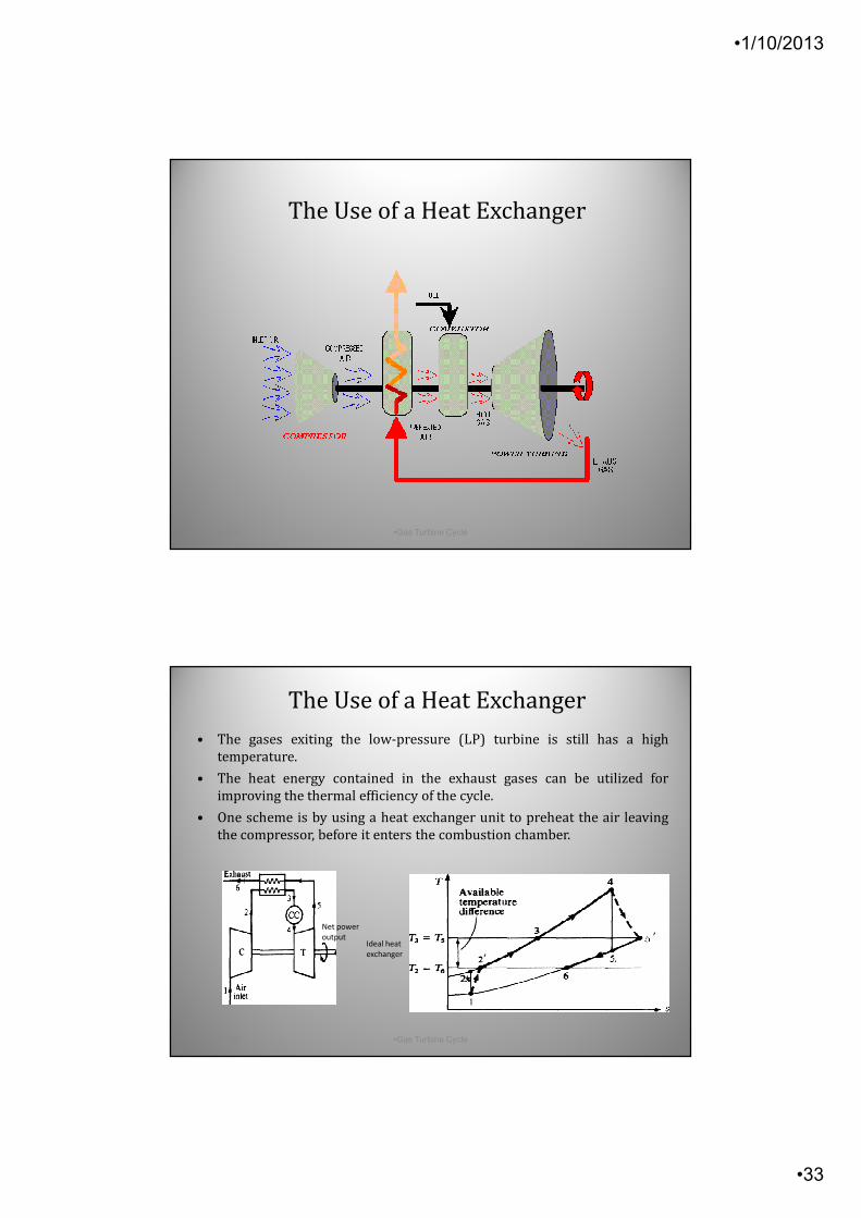
• The gases exiting the low-pressure (LP) turbine is still has a high
temperature.
• The heat energy contained in the exhaust gases can be utilized for
improving the thermal efficiency of the cycle.
• One scheme is by using a heat exchanger unit to preheat the air leaving
the compressor, before it enters the combustion chamber.
Net power
output
’
’Ideal heat
exchanger

•1/10/2013
•34
6'2 TT = '53 TT =
•1-Oct-13 •Gas Turbine Cycle•67
Ideal vs Actual Temperatures
In an ideal cycle, temperatures and
In an actual cycle, temperatures '53 TT <6'2 TT < and
The finite temperature difference is
required, between the compressed air
and the exhaust gases, for the heat
transfer process to take place.
The Use of a Heat Exchanger
’
’
•1-Oct-13 •Gas Turbine Cycle •68
Advantage of Heat Exchanger
When the compressed air is preheated before entering the combustion
chamber, the amount of heat qCC required to raise the temperature of the
working fluid from T2’ to T4, is reduced.
Heat only required to raise the temperature of
the air from T3 to T4. This leads to saving in fuel
consumption and hence the operating cost of
the plant.
Assuming that net work output of the plant
remains unchanged, the thermal efficiency of
the cycle increases by using the heat exchanger.
Actual heat exchanger
’
’
The Use of a Heat Exchanger
•1/10/2013
•35
•1-Oct-13 •Gas Turbine Cycle •69
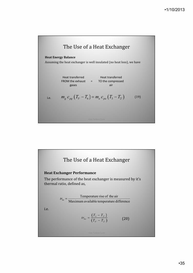
Heat Energy Balance
Assuming the heat exchanger is well insulated (no heat loss), we have
Heat transferred
FROM the exhaust
gases
=
Heat transferred
TO the compressed
air
i.e. (19)
The Use of a Heat Exchanger
( ) ( )5' 6 3 2'g pg a pam c T T m c T T− = −
difference re temperatuavailable Maximum
air theof rise eTemperatur=hetr
•1-Oct-13 •Gas Turbine Cycle •70
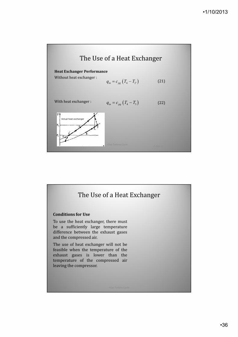
Heat Exchanger Performance
The performance of the heat exchanger is measured by it’s
thermal ratio, defined as,
(20)
i.e.
The Use of a Heat Exchanger
( )( )
3 2 '
5 ' 2 '
he
T Ttr
T T
−=
−
•1/10/2013
•36
•1-Oct-13•Gas Turbine Cycle
•71
Heat Exchanger Performance
Without heat exchanger :
With heat exchanger :
(21)
(22)
Actual heat exchanger
’
’
The Use of a Heat Exchanger
( )4 2'in pgq c T T= −
( )4 3in pgq c T T= −
•1-Oct-13 •Gas Turbine Cycle •72
Conditions for Use
To use the heat exchanger, there must
be a sufficiently large temperature
difference between the exhaust gases
and the compressed air.
The use of heat exchanger will not be
feasible when the temperature of the
exhaust gases is lower than the
temperature of the compressed air
leaving the compressor.
The Use of a Heat Exchanger
•1/10/2013
•37
•1-Oct-13 •Gas Turbine Cycle •73
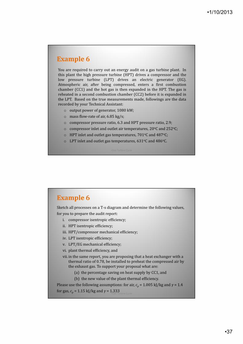
You are required to carry out an energy audit on a gas turbine plant. In
this plant the high pressure turbine (HPT) drives a compressor and the
low pressure turbine (LPT) drives an electric generator (EG).
Atmospheric air, after being compressed, enters a first combustion
chamber (CC1) and the hot gas is then expanded in the HPT. The gas is
reheated in a second combustion chamber (CC2) before it is expanded in
the LPT. Based on the true measurements made, followings are the data
recorded by your Technical Assistant:
o output power of generator, 1080 kW;
o mass flow-rate of air, 6.85 kg/s;
o compressor pressure ratio, 6.3 and HPT pressure ratio, 2.9;
o compressor inlet and outlet air temperatures, 20oC and 252oC;
o HPT inlet and outlet gas temperatures, 701oC and 487oC;
o LPT inlet and outlet gas temperatures, 631oC and 486oC.
Example 6
•1-Oct-13 •Gas Turbine Cycle •74
Sketch all processes on a T-s diagram and determine the following values,
for you to prepare the audit report:
i. compressor isentropic efficiency;
ii. HPT isentropic efficiency;
iii. HPT/compressor mechanical efficiency;
iv. LPT isentropic efficiency;
v. LPT/EG mechanical efficiency;
vi. plant thermal efficiency, and
vii. in the same report, you are proposing that a heat exchanger with a
thermal ratio of 0.78, be installed to preheat the compressed air by
the exhaust gas. To support your proposal what are:
(a) the percentage saving on heat supply by CC1, and
(b) the new value of the plant thermal efficiency.
Please use the following assumptions: for air, cp = 1.005 kJ/kg and γ = 1.4
for gas, cp = 1.15 kJ/kg and γ = 1.333
Example 6
•1/10/2013
•38
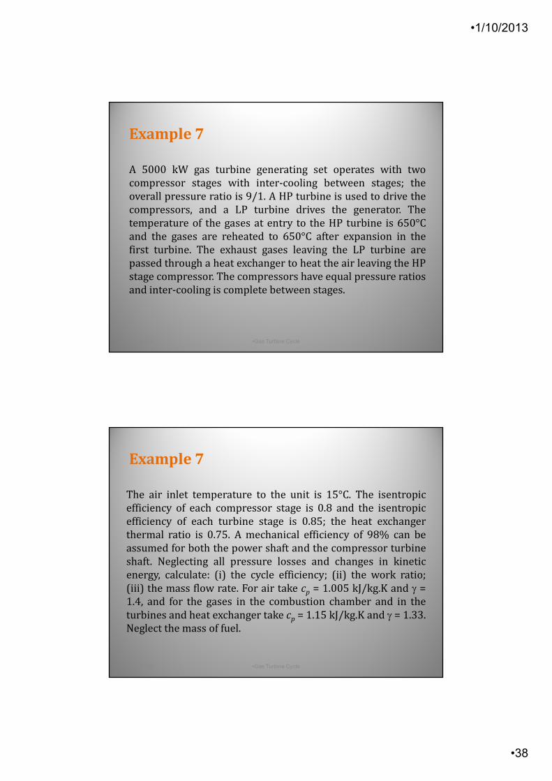
A 5000 kW gas turbine generating set operates with two
compressor stages with inter-cooling between stages; the
overall pressure ratio is 9/1. A HP turbine is used to drive the
compressors, and a LP turbine drives the generator. The
temperature of the gases at entry to the HP turbine is 650°C
and the gases are reheated to 650°C after expansion in the
first turbine. The exhaust gases leaving the LP turbine are
passed through a heat exchanger to heat the air leaving the HP
stage compressor. The compressors have equal pressure ratios
and inter-cooling is complete between stages.
•1-Oct-13 •Gas Turbine Cycle •75
Example 7
The air inlet temperature to the unit is 15°C. The isentropic
efficiency of each compressor stage is 0.8 and the isentropic
efficiency of each turbine stage is 0.85; the heat exchanger
thermal ratio is 0.75. A mechanical efficiency of 98% can be
assumed for both the power shaft and the compressor turbine
shaft. Neglecting all pressure losses and changes in kinetic
energy, calculate: (i) the cycle efficiency; (ii) the work ratio;
(iii) the mass flow rate. For air take cp = 1.005 kJ/kg.K and γ =
1.4, and for the gases in the combustion chamber and in the
turbines and heat exchanger take cp = 1.15 kJ/kg.K and γ = 1.33.
Neglect the mass of fuel.
•1-Oct-13 •Gas Turbine Cycle •76
Example 7
•1/10/2013
•39
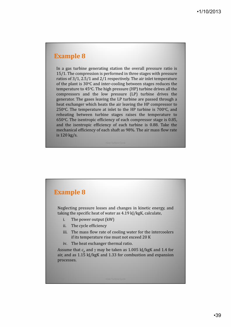
In a gas turbine generating station the overall pressure ratio is
15/1. The compression is performed in three stages with pressure
ratios of 3/1, 2.5/1 and 2/1 respectively. The air inlet temperature
of the plant is 30oC and inter-cooling between stages reduces the
temperature to 45oC. The high pressure (HP) turbine drives all the
compressors and the low pressure (LP) turbine drives the
generator. The gases leaving the LP turbine are passed through a
heat exchanger which heats the air leaving the HP compressor to
250oC. The temperature at inlet to the HP turbine is 700oC, and
reheating between turbine stages raises the temperature to
650oC. The isentropic efficiency of each compressor stage is 0.85,
and the isentropic efficiency of each turbine is 0.88. Take the
mechanical efficiency of each shaft as 98%. The air mass flow rate
is 120 kg/s.
•1-Oct-13 •Gas Turbine Cycle •77
Example 8
Neglecting pressure losses and changes in kinetic energy, and
taking the specific heat of water as 4.19 kJ/kgK, calculate,
i. The power output (kW)
ii. The cycle efficiency
iii. The mass flow rate of cooling water for the intercoolers
if its temperature rise must not exceed 20 K
iv. The heat exchanger thermal ratio.
Assume that cp and γ may be taken as 1.005 kJ/kgK and 1.4 for
air, and as 1.15 kJ/kgK and 1.33 for combustion and expansion
processes.
•1-Oct-13 •Gas Turbine Cycle •78
Example 8