Embed Size (px)
Citation preview
Aeroderivative Gas Turbines
LM2500® to LM2500+DLEGas Turbine Combined CyclePlant Repowering
Authors:
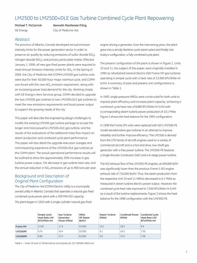
Michael T. McCarrickGE Energy
Kenneth MacKenzie P.Eng.City of Medicine Hat

AbstractThe province of Alberta, Canada developed annual emission
intensity limits for the power generation sector in order to
preserve air quality by reducing emissions of sulfur dioxide (SOx),
nitrogen dioxide (NOx), and primary particulate matter. Effective
January 1, 2006, all new gas-fired power plants were required to
meet Annual Emission Intensity Limits for NOx. In the Spring of
2006, the City of Medicine Hat (COMH) LM2500 gas turbine units
were due for their 50,000-hour major overhaul cycle, and COMH
was faced with this new NOx emission requirement, along with
an increasing power load demand for the city. Working closely
with GE Energy’s Aero Services group, COMH decided to upgrade
the two LM2500 gas turbines to two LM2500+DLE gas turbines to
meet the new emissions requirements and boost power output
to support the growing needs of the city.
This paper will describe the engineering design challenges to
modify the existing LM2500 gas turbine package to accept the
longer and more powerful LM2500+DLE gas turbine, and the
results of the evaluations of the additional mass flow impact on
steam production and combined cycle plant performance.
This paper will also detail the upgrade execution outages and
commissioning experience of the LM2500+DLE gas turbines at
the COMH plant. The actual operational performance results will
be outlined to show the approximately 30% increase in gas
turbine power output, 5% decrease in gas turbine heat rate, and
the annual reduction in NOx emissions of up to 900 tons per year.
Background and Description of Original Plant ConfigurationThe City of Medicine Hat (COMH) Electric Utility is a municipally
owned utility in Alberta, Canada that operates a natural gas-fired
combined cycle power plant with a 209 MW ISO capacity.
The plant began in 1910 with a single-cylinder natural gas-fired
2
engine driving a generator. Over the intervening years, the plant
grew into a strictly Rankine-cycle steam plant and finally into
today’s configuration, a fully combined cycle plant.
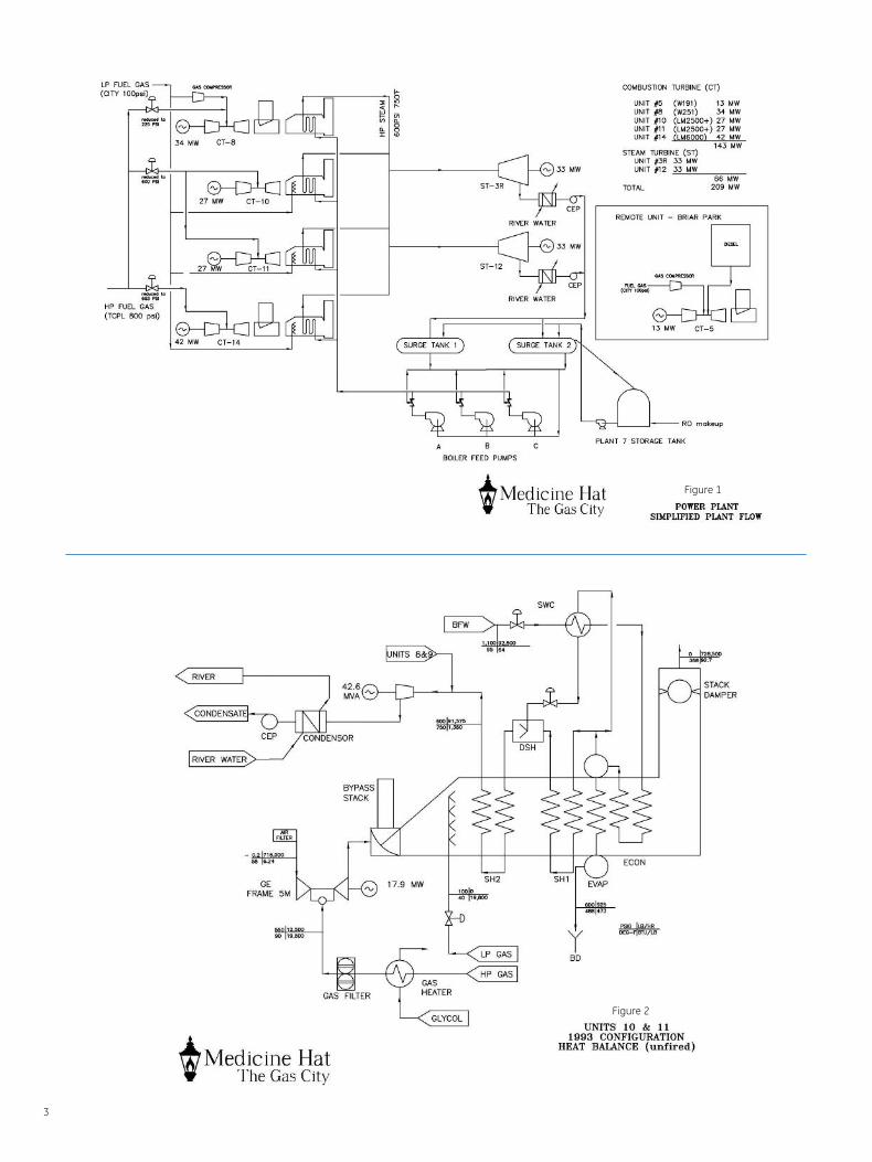
The present configuration of the plant is shown in Figure 1. Units
10 and 11, the subject of this paper, were originally installed in
1990 as refurbished General Electric (GE) Frame 5M gas turbines
operating in simple cycle with a heat rate of 13,900 BTU/kWe-Hr
(LHV). A summary of past and present unit configurations is
shown in Table 1.
In 1993, single-pressure HRSGs were constructed for both units to
improve plant efficiency and increase plant capacity, achieving a
combined cycle heat rate of 8,880 BTU/kWe-Hr (LHV) with
a corresponding steam turbine power production of 10.1 MWe.
Figure 2 shows the heat balance for the 1993 configuration.
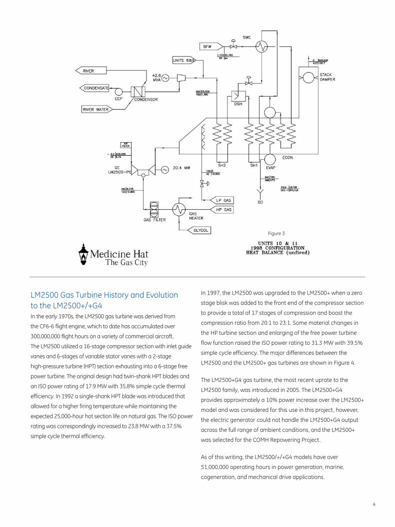
In 1998 the Frame 5M units were replaced with GE’s LM2500-PE
model aeroderivative gas turbines in an attempt to improve
reliability and further improve efficiency. The LM2500 is derived
from the CF6 family of aircraft engines used on a variety of
commercial aircraft and is a hot-end drive, two-shaft gas
generator with a free power turbine. The LM2500-PE features
a Single Annular Combustor (SAC) and a 6-stage power turbine.
The ISO exhaust flow of the LM2500-PE engines, at 499,000 lb/hr
was significantly lower than the previous Frame 5 ISO engine
exhaust rate of 716,000 lbs/hr. Thus, the steam production from
the respective Unit 10 and 11 HRSGs decreased to 6.1 MWe as
measured in steam turbine electric power output. However, the
combined cycle heat rate improved to 7,500 BTU/kWe-Hr (LHV)
as a result of the turbine replacements. Figure 3 shows the heat
balance for the 1998 configuration with the LM2500-PE.
Table 1 – Units 10 and 11 Performance Summaries (at 15C 60%RH 666m el.)
Simple CycleHeat Rate LHV BTU/MWe-Hr)
Gas Turbine Generator Power (MWe)
HRSG HP Steam(lb/hr)
Steam Turbine(MWe)
Combined Power (MWe)
Combined CycleHeat Rate LHV BTU/MWe-Hr)
Frame 5M 13.90 17.9 91,000 10.1 28.0 8.9
LM2500PE 9.74 20.4 55,000 6.1 26.5 7.50
LM2500PR 8.88 27.0 62,000 6.9 33.9 7.08
LM2500 to LM2500+DLE Gas Turbine Combined Cycle Plant RepoweringMichael T. McCarrick
GE Energy
Kenneth MacKenzie P.Eng.
City of Medicine Hat
3
Figure 2
Figure 1
4
LM2500 Gas Turbine History and Evolution to the LM2500+/+G4In the early 1970s, the LM2500 gas turbine was derived from
the CF6-6 flight engine, which to date has accumulated over
300,000,000 flight hours on a variety of commercial aircraft.
The LM2500 utilized a 16-stage compressor section with inlet guide
vanes and 6-stages of variable stator vanes with a 2-stage
high-pressure turbine (HPT) section exhausting into a 6-stage free
power turbine. The original design had twin-shank HPT blades and
an ISO power rating of 17.9 MW with 35.8% simple cycle thermal
efficiency. In 1992 a single-shank HPT blade was introduced that
allowed for a higher firing temperature while maintaining the
expected 25,000-hour hot section life on natural gas. The ISO power
rating was correspondingly increased to 23.8 MW with a 37.5%
simple cycle thermal efficiency.
In 1997, the LM2500 was upgraded to the LM2500+ when a zero
stage blisk was added to the front end of the compressor section
to provide a total of 17 stages of compression and boost the
compression ratio from 20:1 to 23:1. Some material changes in
the HP turbine section and enlarging of the free power turbine
flow function raised the ISO power rating to 31.3 MW with 39.5%
simple cycle efficiency. The major differences between the
LM2500 and the LM2500+ gas turbines are shown in Figure 4.
The LM2500+G4 gas turbine, the most recent uprate to the
LM2500 family, was introduced in 2005. The LM2500+G4
provides approximately a 10% power increase over the LM2500+
model and was considered for this use in this project, however,
the electric generator could not handle the LM2500+G4 output
across the full range of ambient conditions, and the LM2500+
was selected for the COMH Repowering Project.
As of this writing, the LM2500/+/+G4 models have over
51,000,000 operating hours in power generation, marine,
cogeneration, and mechanical drive applications.
Figure 3
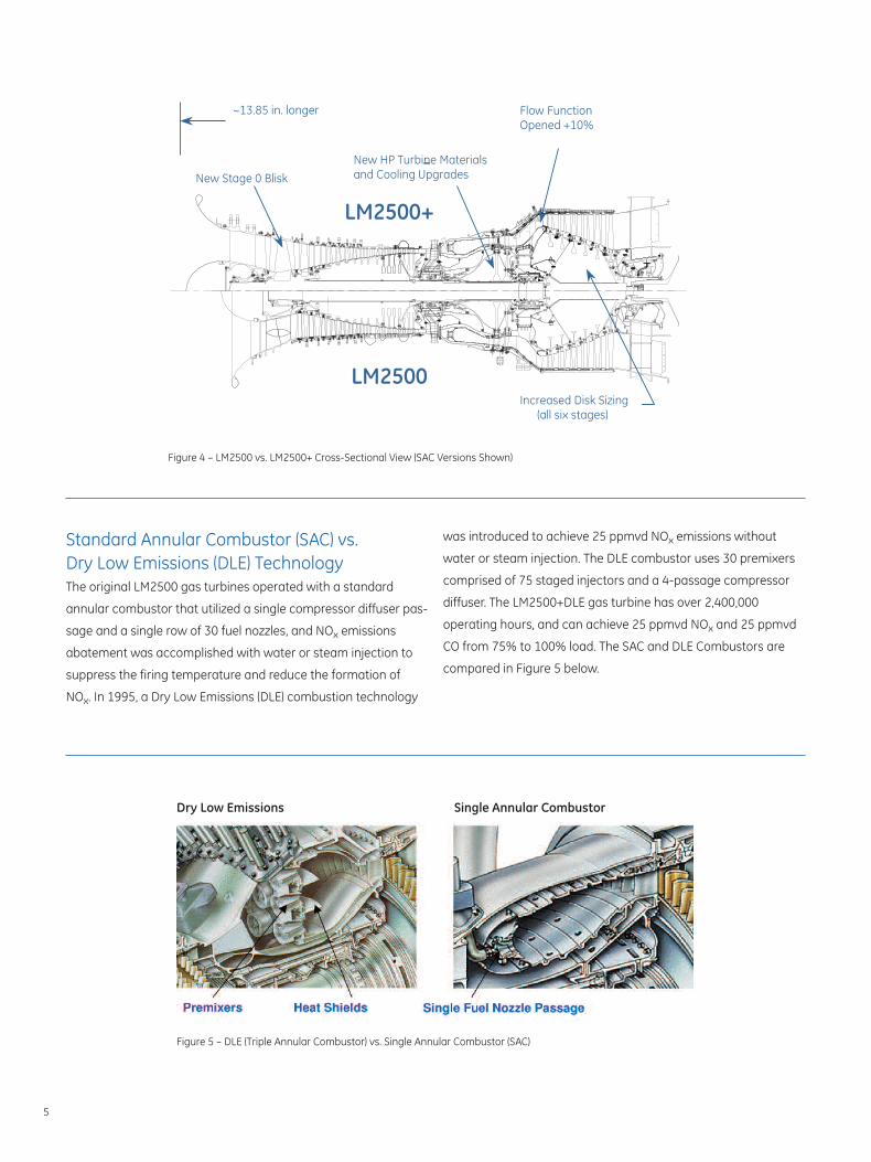
Figure 4 – LM2500 vs. LM2500+ Cross-Sectional View (SAC Versions Shown)
Figure 5 – DLE (Triple Annular Combustor) vs. Single Annular Combustor (SAC)
was introduced to achieve 25 ppmvd NOx emissions without
water or steam injection. The DLE combustor uses 30 premixers
comprised of 75 staged injectors and a 4-passage compressor
diffuser. The LM2500+DLE gas turbine has over 2,400,000
operating hours, and can achieve 25 ppmvd NOx and 25 ppmvd
CO from 75% to 100% load. The SAC and DLE Combustors are
compared in Figure 5 below.
Standard Annular Combustor (SAC) vs. Dry Low Emissions (DLE) TechnologyThe original LM2500 gas turbines operated with a standard
annular combustor that utilized a single compressor diffuser pas-
sage and a single row of 30 fuel nozzles, and NOx emissions
abatement was accomplished with water or steam injection to
suppress the firing temperature and reduce the formation of
NOx. In 1995, a Dry Low Emissions (DLE) combustion technology
Dry Low Emissions Single Annular Combustor
5
Repowering Drivers and BenefitsThe original LM2500-PE gas turbines were scheduled to achieve
their 50,000-hour major overhaul cycle in 2006, and the COMH
was faced with four options:
1. Rebuild the existing LM2500 SAC engines at the depot
to achieve Zero Time.
2. Replace existing LM2500 SAC engines with identical new
LM2500 SAC units.
3. Replace the LM2500 SAC engines with new LM2500 DLE
engines.
4. Increase the capacity and reduce emissions by replacing
the LM2500 SAC engines with LM2500+ DLE engines.
To comply with emissions reductions commitments made to
regulatory agencies, and to increase plant capacity with a
marginally improved heat rate, it was decided to pursue Option
4, replacement of the engines with the LM2500+ DLE engines,
known formally as the LM2500-PR model.
1. Emissions ReductionsIn prior years, the COMH had made commitments to the
regulator, Alberta Environment (AENV) that would see NOx
abatement technologies implemented on Units 10 and 11 prior
to renewal of the environmental permit in 2009.
The LM2500-PE units had historically and consistently produced
NOx emissions of approximately 170 ppmvd, equivalent to a
mass emission of 125 pounds per hour of NOx.
Under the AENV’s 2006 Emission Intensity Limits for NOx, new
units in the 20 to 60 MW range (that range covers the LM2500
models) would be required to achieve an intensity of less than 0.4
kg/MW-Hr.
As shown in Table 2, the original LM2500-PE units produced NOx
emission intensities well in excess of the 2006 Limits. NOx
abatement equipment such as Selective Catalytic Reduction
(SCR) or water/steam injection would have been necessary to
achieve the 2006 limits using the LM2500 SAC engine.
The LM2500-PR was predicted, and has proven capable in
meeting the 2006 limits.
2. Increased Power OutputThe COMH electrical load in the 21st century has been growing
at an average of 2% per year, with corresponding increases in
air-conditioning load peaks during the summer months.
Replacing the LM2500-PE with a similar engine would obviously
do nothing to increase plant capacity to meet this increasing
load. On the other hand, the LM2500-PR offered a modest
7.4 MWe increase in combined cycle capacity per unit,
well within the regulatory limits set on the amount of electrical
generation the City may hold.
3. Improved Heat RateThe LM2500-PR features a higher compression ratio (23:1) than
the LM2500-PE (20:1), and consequentially is a more efficient
turbine. The guaranteed simple cycle heat rate for the
LM2500-PR was 9,238 Btu/kWe·Hr LHV versus the guarantee rate
for the LM2500-PE at 9,743 Btu/kWe·Hr LHV, a 5% improvement.
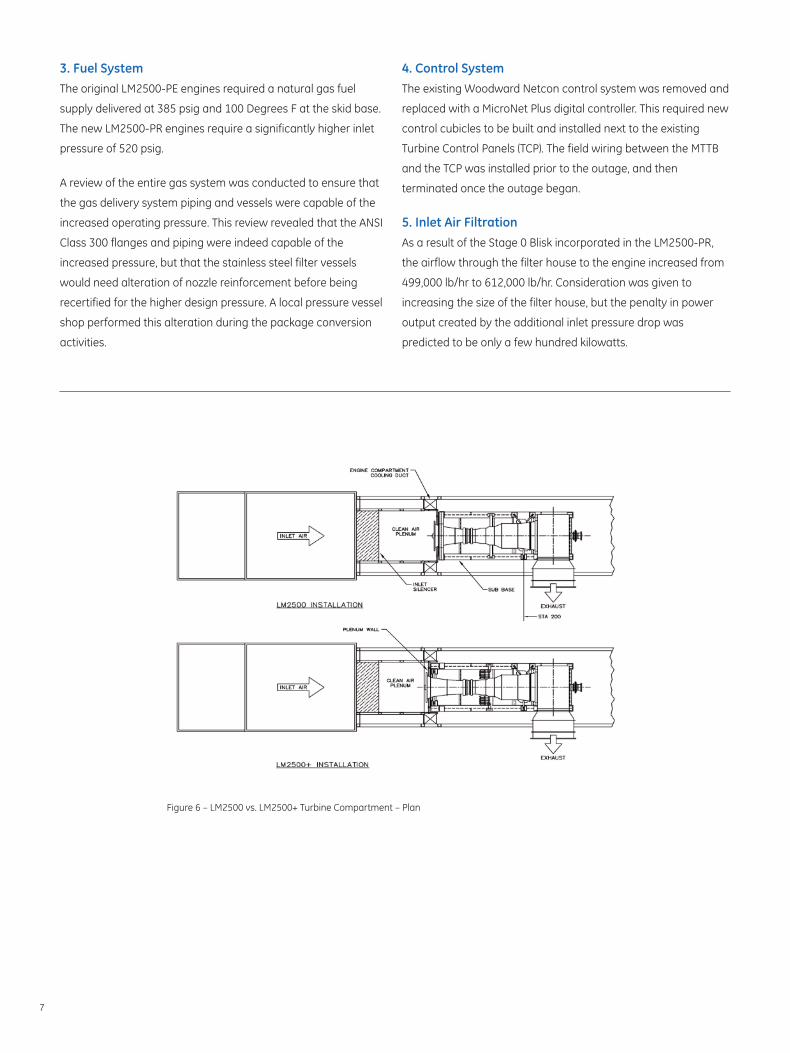
Technical Challengers Encountered in LM2500 to LM2500+DLE Repowering1. Accommodation of Longer EngineBy far the biggest challenge in the project was altering the
turbine compartments to fit the longer engines. As shown in
Figures 6 and 7, the plenum wall was moved 13-13/16” and the
main structural base was extended a proportionate amount.
The front engine mounts were changed from the top-hung
"horseshoe" frame to a link style system supported from the
subbase, which also required extension.
The original turbine compartment crane was removed and
replaced with a higher capacity unit due to the increased weight
of the PR engine. The engine-lifting beam required extensive
modifications as a result of reduced headroom from the
modifications.
2. Capacity of GeneratorThe generator supplied in 1998 with the original LM2500-SAC
package is a Brush Electric Machines Ltd. Type BDAX-7-167ESS
rated at 35,412 KVA at a 0.85 Power Factor.
On cold winter days, the LM2500-PR turbine is capable of
producing 30.1 MW with a corresponding turbine inlet temperature
of 32 degrees Fahrenheit. This power output matches exactly the
Brush generator capability at the 0.85 Power Factor and thus no
changes to the generator were required. The mechanical
coupling connecting the turbine to generator was found to be
inadequate for the higher mechanical power transmission duty
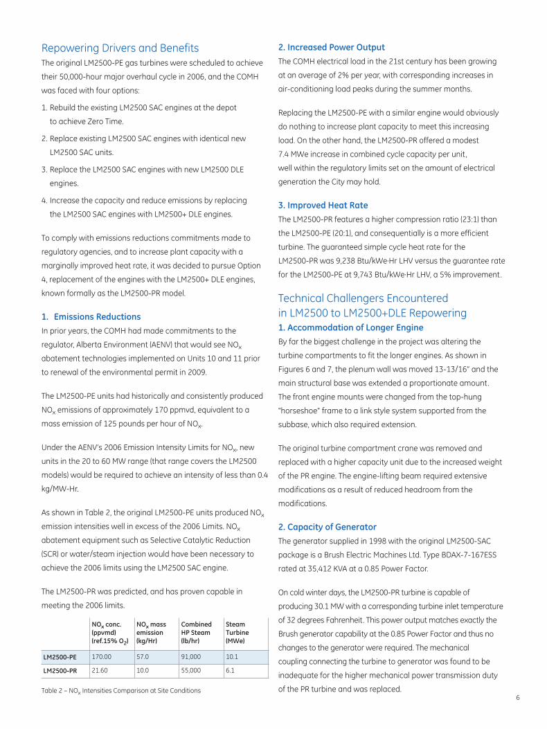
of the PR turbine and was replaced.Table 2 – NOx Intensities Comparison at Site Conditions
NOx conc.(ppvmd)(ref.15% O2)
NOx massemission(kg/Hr)
Combined HP Steam(lb/hr)
Steam Turbine(MWe)
LM2500-PE 170.00 57.0 91,000 10.1
LM2500-PR 21.60 10.0 55,000 6.1
6
3. Fuel SystemThe original LM2500-PE engines required a natural gas fuel
supply delivered at 385 psig and 100 Degrees F at the skid base.
The new LM2500-PR engines require a significantly higher inlet
pressure of 520 psig.
A review of the entire gas system was conducted to ensure that
the gas delivery system piping and vessels were capable of the
increased operating pressure. This review revealed that the ANSI
Class 300 flanges and piping were indeed capable of the
increased pressure, but that the stainless steel filter vessels
would need alteration of nozzle reinforcement before being
recertified for the higher design pressure. A local pressure vessel
shop performed this alteration during the package conversion
activities.
4. Control SystemThe existing Woodward Netcon control system was removed and
replaced with a MicroNet Plus digital controller. This required new
control cubicles to be built and installed next to the existing
Turbine Control Panels (TCP). The field wiring between the MTTB
and the TCP was installed prior to the outage, and then
terminated once the outage began.
5. Inlet Air FiltrationAs a result of the Stage 0 Blisk incorporated in the LM2500-PR,
the airflow through the filter house to the engine increased from
499,000 lb/hr to 612,000 lb/hr. Consideration was given to
increasing the size of the filter house, but the penalty in power
output created by the additional inlet pressure drop was
predicted to be only a few hundred kilowatts.
Figure 6 – LM2500 vs. LM2500+ Turbine Compartment – Plan
7
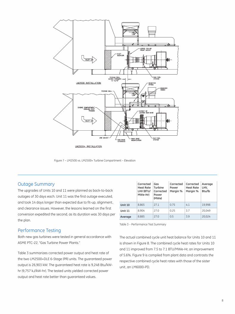
Figure 7 – LM2500 vs. LM2500+ Turbine Compartment – Elevation
Outage SummaryThe upgrades of Units 10 and 11 were planned as back-to-back
outages of 30 days each. Unit 11 was the first outage executed,
and took 14 days longer than expected due to fit-up, alignment,
and clearance issues. However, the lessons learned on the first
conversion expedited the second, as its duration was 30 days per
the plan.
Performance TestingBoth new gas turbines were tested in general accordance with
ASME PTC-22, "Gas Turbine Power Plants."
Table 3 summarizes corrected power output and heat rate of
the two LM2500+DLE 6-Stage (PR) units. The guaranteed power
output is 26,903 kW. The guaranteed heat rate is 9,248 Btu/kW-
hr (9,757 kJ/kW-hr). The tested units yielded corrected power
output and heat rate better than guaranteed values.
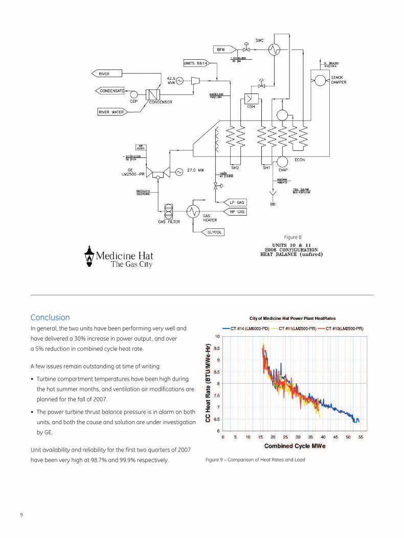
The actual combined cycle unit heat balance for Units 10 and 11
is shown in Figure 8. The combined cycle heat rates for Units 10
and 11 improved from 7.5 to 7.1 BTU/MWe-Hr, an improvement
of 5.6%. Figure 9 is compiled from plant data and contrasts the
respective combined cycle heat rates with those of the sister
unit, an LM6000-PD.
Table 3 – Performance Test Summary
CorrectedHeat RateLHV (BTU/MWe-Hr)
Gas TurbineCorrectedPower(MWe)
CorrectedPower Margin %
CorrectedHeat RateMargin %
AverageLHV,Btu/lb
Unit 10 8.865 27.1 0.75 4.1 19,998
Unit 11 8.904 27.0 0.25 3.7 20,049
Average 8.885 27.0 0.5 3.9 20,024
8
ConclusionIn general, the two units have been performing very well and
have delivered a 30% increase in power output, and over
a 5% reduction in combined cycle heat rate.
A few issues remain outstanding at time of writing:
• Turbine compartment temperatures have been high during
the hot summer months, and ventilation air modifications are
planned for the fall of 2007.
• The power turbine thrust balance pressure is in alarm on both
units, and both the cause and solution are under investigation
by GE.
Unit availability and reliability for the first two quarters of 2007
have been very high at 98.7% and 99.9% respectively.
9
Figure 8
Figure 9 – Comparison of Heat Rates and Load
References1. Alberta Regulation No. 33/2006, Environmental Protection
and Enhancement Act, Emissions Trading Regulation.
2. Figures 6 and 7 provided courtesy of Fern Engineering of
Pocasset, Massachusetts. Fern provided engineering design
services for the package modifications, and have provided
similar services on other Gas Turbine projects.
3. GER 4250 “The LM2500+G4 Aeroderivative Gas Turbine for
Marine and Industrial Applications” by Gilbert H. Badeer,
GE Energy September 2005.

www. ge-aero.com
LM2500 is a trademark of General Electric Company.Copyright © 2012, General Electric Company. All rights reserved.
GEA18640A (10/2012)


![Welcome! [] Webinars/Webinar 12... · Welcome! Webinar #12: ... either for HPT stator cooing or for turbine blade clearance control . Different GT Models in ... (LM2500, LM6000 etc)](https://img.pdfslide.us/doc/110x75/5b0d37357f8b9a2f788d5e75/welcome-webinarswebinar-12welcome-webinar-12-either-for-hpt-stator.jpg)


![THESIS - DTIC · 2011. 5. 13. · LM2500 gas turbine engine. [Ref. 1] The LM2500 is a marinized derivative of the CF6/TF39 aircraft ... chosen to optimize the thermo-mechanical criteria](https://img.pdfslide.us/doc/110x75/5fe884521fa786626c4c6966/thesis-dtic-2011-5-13-lm2500-gas-turbine-engine-ref-1-the-lm2500-is-a.jpg)


![DLE-35RA - Hobbico - Hobbico, Inc. - largest U.S ...manuals.hobbico.com/dle/dleg0435-manual.pdfDLE with Manual Choke Main Engine − 2.08lb [947g] ... DLE-35RA Gas Engine with DLE](https://img.pdfslide.us/doc/110x75/5abf1f1d7f8b9a3a428dcf03/dle-35ra-hobbico-hobbico-inc-largest-us-with-manual-choke-main-engine.jpg)