Embed Size (px)
Citation preview
JUNIPER CHASSIS CLUSTER CONFIGURATION WITH SRX-1500S
This article identifies resources for understanding, configuring and verifying the "High availability or Chassis cluster" (in Juniper's term) on Juniper's SRX 1500 Series firewall.
You can use this article as a reference to configuring the chassis cluster on your SRX firewalls. This configuration has been tested and proven to be working as expected. I hope this help you.
SUMMARY:
• Juniper SRX-1500 Chassis Cluster Configuration Template • Deep dive of Chassis Cluster Configuration on SRX-1500
1) Pre-requisite a) Understand The control link (Control Plane) b) Understand The Fabric link (Data Plane)
2) Enable the cluster mode a) Understand Cluster ID b) Understand Cluster Node
3) Verify that chassis cluster was successful by running 4) Configure management interfaces (fxp0) for each of the nodes.
a) Understand Slot Numbering with the SRX-1500 Chassis Cluster 5) Configure the Fabric links in the cluster 6) Configure the Redundancy Groups 0 and 1
a) Understand Redundancy group 7) Configure interface monitoring
a) Understand Interface monitoring 8) Enable and apply Redundancy Ethernet interfaces
a) Understand Redundant Ethernet Interface 9) Configure Redundancy Ethernet interfaces
• Verification Commands
Ashutosh Patel
CCIE #52560 Network Security Architect https://www.linkedin.com/in/patelashutosh
ASHUTOSH PATEL https://www.linkedin.com/in/patelashutosh
2
Juniper Networks SRX Series Services Gateways can be configured to operate in cluster mode, where a pair of devices can be connected together and configured to operate as a single node, providing device, interface, and service level redundancy. Let’s get started.
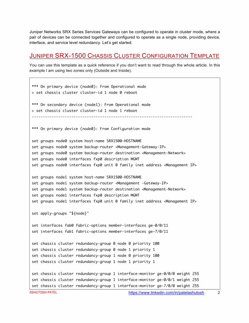
JUNIPER SRX-1500 CHASSIS CLUSTER CONFIGURATION TEMPLATE You can use this template as a quick reference if you don’t want to read through the whole article. In this example I am using two zones only (Outside and Inside).
*** On primary device (node0): From Operational mode > set chassis cluster cluster-id 1 node 0 reboot *** On secondary device (node1): From Operational mode > set chassis cluster cluster-id 1 node 1 reboot ------------------------------------------------------------------------- *** On primary device (node0): From Configuration mode set groups node0 system host-name SRX1500-HOSTNAME set groups node0 system backup-router <Management-Gateway-IP> set groups node0 system backup-router destination <Management-Network> set groups node0 interfaces fxp0 description MGMT set groups node0 interfaces fxp0 unit 0 family inet address <Management IP> set groups node1 system host-name SRX1500-HOSTNAME set groups node1 system backup-router <Management -Gateway-IP> set groups node1 system backup-router destination <Management-Network> set groups node1 interfaces fxp0 description MGMT set groups node1 interfaces fxp0 unit 0 family inet address <Management IP> set apply-groups "${node}" set interfaces fab0 fabric-options member-interfaces ge-0/0/11 set interfaces fab1 fabric-options member-interfaces ge-7/0/11 set chassis cluster redundancy-group 0 node 0 priority 100 set chassis cluster redundancy-group 0 node 1 priority 1 set chassis cluster redundancy-group 1 node 0 priority 100 set chassis cluster redundancy-group 1 node 1 priority 1 set chassis cluster redundancy-group 1 interface-monitor ge-0/0/0 weight 255 set chassis cluster redundancy-group 1 interface-monitor ge-0/0/1 weight 255 set chassis cluster redundancy-group 1 interface-monitor ge-7/0/0 weight 255
ASHUTOSH PATEL https://www.linkedin.com/in/patelashutosh
3
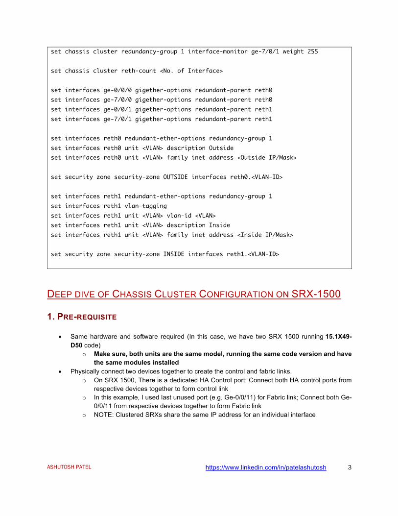
set chassis cluster redundancy-group 1 interface-monitor ge-7/0/1 weight 255 set chassis cluster reth-count <No. of Interface> set interfaces ge-0/0/0 gigether-options redundant-parent reth0 set interfaces ge-7/0/0 gigether-options redundant-parent reth0 set interfaces ge-0/0/1 gigether-options redundant-parent reth1 set interfaces ge-7/0/1 gigether-options redundant-parent reth1 set interfaces reth0 redundant-ether-options redundancy-group 1 set interfaces reth0 unit <VLAN> description Outside set interfaces reth0 unit <VLAN> family inet address <Outside IP/Mask> set security zone security-zone OUTSIDE interfaces reth0.<VLAN-ID> set interfaces reth1 redundant-ether-options redundancy-group 1 set interfaces reth1 vlan-tagging set interfaces reth1 unit <VLAN> vlan-id <VLAN> set interfaces reth1 unit <VLAN> description Inside set interfaces reth1 unit <VLAN> family inet address <Inside IP/Mask> set security zone security-zone INSIDE interfaces reth1.<VLAN-ID>
DEEP DIVE OF CHASSIS CLUSTER CONFIGURATION ON SRX-1500
1. PRE-REQUISITE
• Same hardware and software required (In this case, we have two SRX 1500 running 15.1X49-D50 code)
o Make sure, both units are the same model, running the same code version and have the same modules installed
• Physically connect two devices together to create the control and fabric links. o On SRX 1500, There is a dedicated HA Control port; Connect both HA control ports from
respective devices together to form control link o In this example, I used last unused port (e.g. Ge-0/0/11) for Fabric link; Connect both Ge-
0/0/11 from respective devices together to form Fabric link o NOTE: Clustered SRXs share the same IP address for an individual interface
ASHUTOSH PATEL https://www.linkedin.com/in/patelashutosh
4
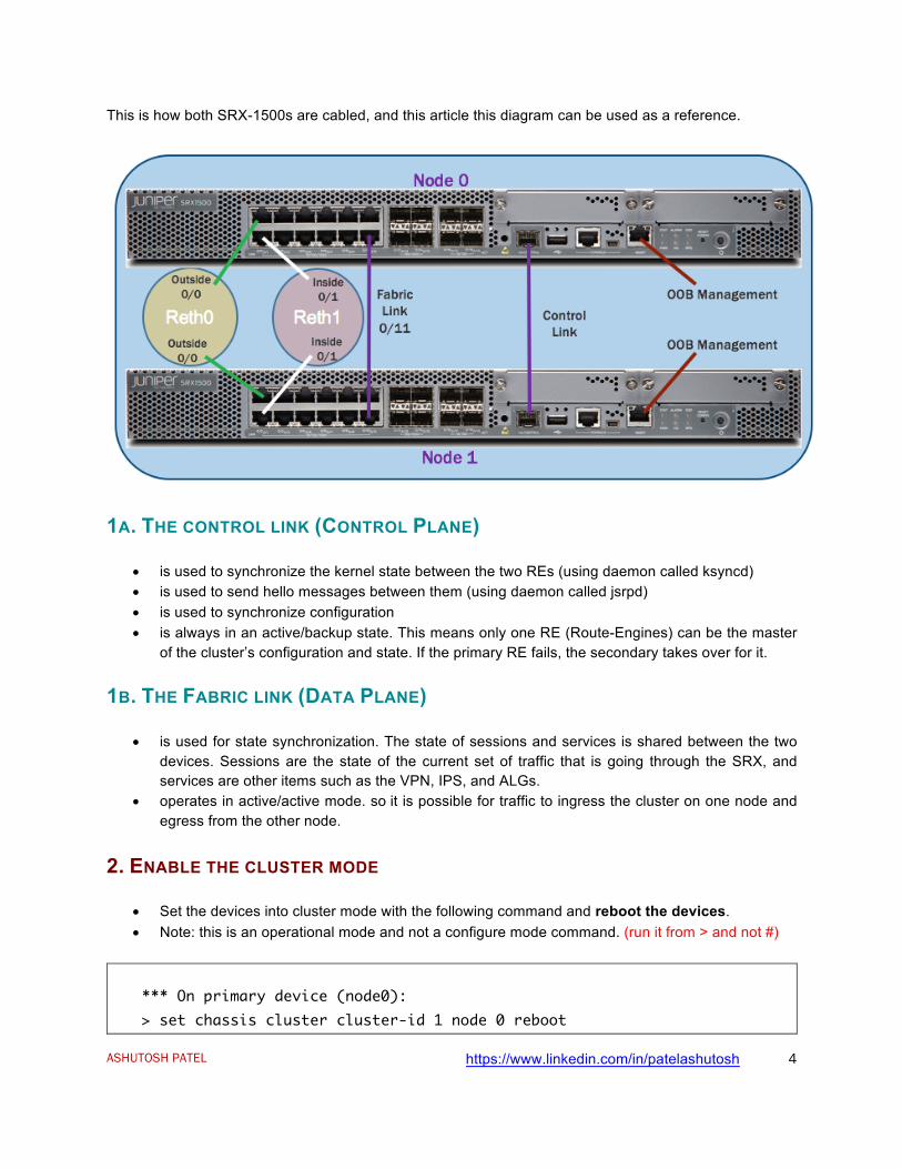
This is how both SRX-1500s are cabled, and this article this diagram can be used as a reference.
1A. THE CONTROL LINK (CONTROL PLANE)
• is used to synchronize the kernel state between the two REs (using daemon called ksyncd) • is used to send hello messages between them (using daemon called jsrpd) • is used to synchronize configuration • is always in an active/backup state. This means only one RE (Route-Engines) can be the master
of the cluster’s configuration and state. If the primary RE fails, the secondary takes over for it.
1B. THE FABRIC LINK (DATA PLANE)
• is used for state synchronization. The state of sessions and services is shared between the two devices. Sessions are the state of the current set of traffic that is going through the SRX, and services are other items such as the VPN, IPS, and ALGs.
• operates in active/active mode. so it is possible for traffic to ingress the cluster on one node and egress from the other node.
2. ENABLE THE CLUSTER MODE
• Set the devices into cluster mode with the following command and reboot the devices. • Note: this is an operational mode and not a configure mode command. (run it from > and not #)
*** On primary device (node0): > set chassis cluster cluster-id 1 node 0 reboot
ASHUTOSH PATEL https://www.linkedin.com/in/patelashutosh
5
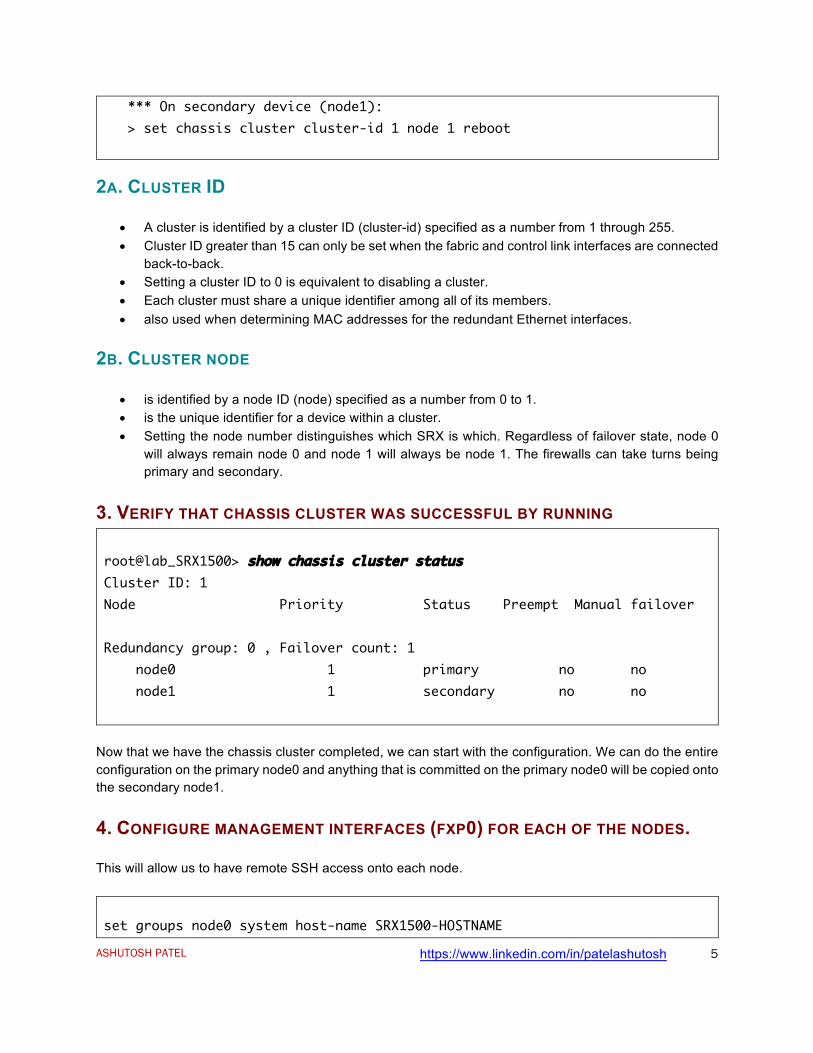
*** On secondary device (node1): > set chassis cluster cluster-id 1 node 1 reboot
2A. CLUSTER ID
• A cluster is identified by a cluster ID (cluster-id) specified as a number from 1 through 255. • Cluster ID greater than 15 can only be set when the fabric and control link interfaces are connected
back-to-back. • Setting a cluster ID to 0 is equivalent to disabling a cluster. • Each cluster must share a unique identifier among all of its members. • also used when determining MAC addresses for the redundant Ethernet interfaces.
2B. CLUSTER NODE
• is identified by a node ID (node) specified as a number from 0 to 1. • is the unique identifier for a device within a cluster. • Setting the node number distinguishes which SRX is which. Regardless of failover state, node 0
will always remain node 0 and node 1 will always be node 1. The firewalls can take turns being primary and secondary.
3. VERIFY THAT CHASSIS CLUSTER WAS SUCCESSFUL BY RUNNING root@lab_SRX1500> show chassis cluster status Cluster ID: 1 Node Priority Status Preempt Manual failover Redundancy group: 0 , Failover count: 1 node0 1 primary no no node1 1 secondary no no
Now that we have the chassis cluster completed, we can start with the configuration. We can do the entire configuration on the primary node0 and anything that is committed on the primary node0 will be copied onto the secondary node1.
4. CONFIGURE MANAGEMENT INTERFACES (FXP0) FOR EACH OF THE NODES.
This will allow us to have remote SSH access onto each node.
set groups node0 system host-name SRX1500-HOSTNAME
ASHUTOSH PATEL https://www.linkedin.com/in/patelashutosh
6
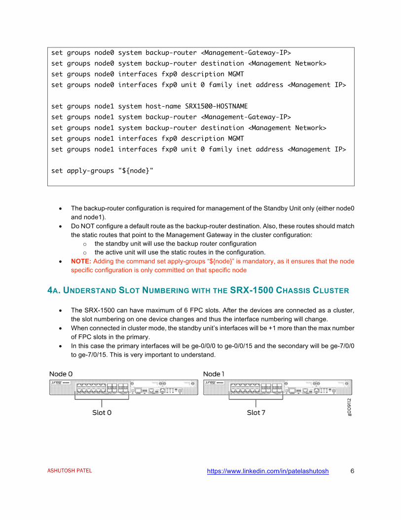
set groups node0 system backup-router <Management-Gateway-IP> set groups node0 system backup-router destination <Management Network> set groups node0 interfaces fxp0 description MGMT set groups node0 interfaces fxp0 unit 0 family inet address <Management IP> set groups node1 system host-name SRX1500-HOSTNAME set groups node1 system backup-router <Management-Gateway-IP> set groups node1 system backup-router destination <Management Network> set groups node1 interfaces fxp0 description MGMT set groups node1 interfaces fxp0 unit 0 family inet address <Management IP> set apply-groups "${node}"
• The backup-router configuration is required for management of the Standby Unit only (either node0 and node1).
• Do NOT configure a default route as the backup-router destination. Also, these routes should match the static routes that point to the Management Gateway in the cluster configuration:
o the standby unit will use the backup router configuration o the active unit will use the static routes in the configuration.
• NOTE: Adding the command set apply-groups “${node}” is mandatory, as it ensures that the node specific configuration is only committed on that specific node
4A. UNDERSTAND SLOT NUMBERING WITH THE SRX-1500 CHASSIS CLUSTER
• The SRX-1500 can have maximum of 6 FPC slots. After the devices are connected as a cluster, the slot numbering on one device changes and thus the interface numbering will change.
• When connected in cluster mode, the standby unit’s interfaces will be +1 more than the max number of FPC slots in the primary.
• In this case the primary interfaces will be ge-0/0/0 to ge-0/0/15 and the secondary will be ge-7/0/0 to ge-7/0/15. This is very important to understand.
ASHUTOSH PATEL https://www.linkedin.com/in/patelashutosh
7
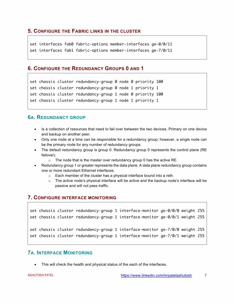
5. CONFIGURE THE FABRIC LINKS IN THE CLUSTER set interfaces fab0 fabric-options member-interfaces ge-0/0/11 set interfaces fab1 fabric-options member-interfaces ge-7/0/11
6. CONFIGURE THE REDUNDANCY GROUPS 0 AND 1 set chassis cluster redundancy-group 0 node 0 priority 100 set chassis cluster redundancy-group 0 node 1 priority 1 set chassis cluster redundancy-group 1 node 0 priority 100 set chassis cluster redundancy-group 1 node 1 priority 1
6A. REDUNDANCY GROUP
• Is a collection of resources that need to fail over between the two devices. Primary on one device and backup on another peer.
• Only one node at a time can be responsible for a redundancy group; however, a single node can be the primary node for any number of redundancy groups.
• The default redundancy group is group 0. Redundancy group 0 represents the control plane (RE failover).
o The node that is the master over redundancy group 0 has the active RE. • Redundancy group 1 or greater represents the data plane. A data plane redundancy group contains
one or more redundant Ethernet interfaces. o Each member of the cluster has a physical interface bound into a reth. o The active node’s physical interface will be active and the backup node’s interface will be
passive and will not pass traffic.
7. CONFIGURE INTERFACE MONITORING set chassis cluster redundancy-group 1 interface-monitor ge-0/0/0 weight 255 set chassis cluster redundancy-group 1 interface-monitor ge-0/0/1 weight 255 set chassis cluster redundancy-group 1 interface-monitor ge-7/0/0 weight 255 set chassis cluster redundancy-group 1 interface-monitor ge-7/0/1 weight 255
7A. INTERFACE MONITORING
• This will check the health and physical status of the each of the interfaces.
ASHUTOSH PATEL https://www.linkedin.com/in/patelashutosh
8
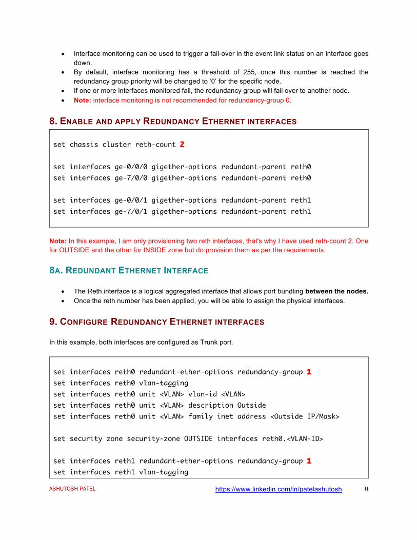
• Interface monitoring can be used to trigger a fail-over in the event link status on an interface goes down.
• By default, interface monitoring has a threshold of 255, once this number is reached the redundancy group priority will be changed to ‘0’ for the specific node.
• If one or more interfaces monitored fail, the redundancy group will fail over to another node. • Note: interface monitoring is not recommended for redundancy-group 0.
8. ENABLE AND APPLY REDUNDANCY ETHERNET INTERFACES set chassis cluster reth-count 2 set interfaces ge-0/0/0 gigether-options redundant-parent reth0 set interfaces ge-7/0/0 gigether-options redundant-parent reth0 set interfaces ge-0/0/1 gigether-options redundant-parent reth1 set interfaces ge-7/0/1 gigether-options redundant-parent reth1
Note: In this example, I am only provisioning two reth interfaces, that's why I have used reth-count 2. One for OUTSIDE and the other for INSIDE zone but do provision them as per the requirements.
8A. REDUNDANT ETHERNET INTERFACE
• The Reth interface is a logical aggregated interface that allows port bundling between the nodes. • Once the reth number has been applied, you will be able to assign the physical interfaces.
9. CONFIGURE REDUNDANCY ETHERNET INTERFACES
In this example, both interfaces are configured as Trunk port.
set interfaces reth0 redundant-ether-options redundancy-group 1 set interfaces reth0 vlan-tagging set interfaces reth0 unit <VLAN> vlan-id <VLAN> set interfaces reth0 unit <VLAN> description Outside set interfaces reth0 unit <VLAN> family inet address <Outside IP/Mask> set security zone security-zone OUTSIDE interfaces reth0.<VLAN-ID> set interfaces reth1 redundant-ether-options redundancy-group 1 set interfaces reth1 vlan-tagging
ASHUTOSH PATEL https://www.linkedin.com/in/patelashutosh
9
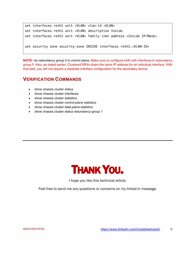
set interfaces reth1 unit <VLAN> vlan-id <VLAN> set interfaces reth1 unit <VLAN> description Inside set interfaces reth1 unit <VLAN> family inet address <Inside IP/Mask> set security zone security-zone INSIDE interfaces reth1.<VLAN-ID>
NOTE: As redundancy group 0 is control plane; Make sure to configure both reth interfaces in redundancy group 1. Also, as stated earlier, Clustered SRXs share the same IP address for an individual interface. With that said, you will not require a separate interface configuration for the secondary device.
VERIFICATION COMMANDS
• show chassis cluster status • show chassis cluster interfaces • show chassis cluster statistics • show chassis cluster control-plane statistics • show chassis cluster data-plane statistics • show chassis cluster status redundancy-group 1
THANK YOU. I hope you like this technical article.
Feel free to send me any questions or concerns on my linked-in message.