Embed Size (px)
Citation preview
APPLICATION NOTE
Copyright © 2010, Juniper Networks, Inc. 1
BrANCh SrX SErIES ANd J SErIES SELECTIvE PACkET SErvICES Configuring Selective Packet Services on Branch SrX Series Services Gateways and J Series Services routers
2 Copyright © 2010, Juniper Networks, Inc.
APPLICATION NOTE - Branch SrX Series and J Series Selective Packet Services
Table of Contents
Introduction . . . . . . . . . . . . . . . . . . . . . . . . . . . . . . . . . . . . . . . . . . . . . . . . . . . . . . . . . . . . . . . . . . . . . . . . . . . . . . . . . . . . . . . . . . . . . . . . . . . . . .3
Scope . . . . . . . . . . . . . . . . . . . . . . . . . . . . . . . . . . . . . . . . . . . . . . . . . . . . . . . . . . . . . . . . . . . . . . . . . . . . . . . . . . . . . . . . . . . . . . . . . . . . . . . . . . .3
design Considerations . . . . . . . . . . . . . . . . . . . . . . . . . . . . . . . . . . . . . . . . . . . . . . . . . . . . . . . . . . . . . . . . . . . . . . . . . . . . . . . . . . . . . . . . . . . .3
hardware requirements . . . . . . . . . . . . . . . . . . . . . . . . . . . . . . . . . . . . . . . . . . . . . . . . . . . . . . . . . . . . . . . . . . . . . . . . . . . . . . . . . . . . . . . .3
Software requirements . . . . . . . . . . . . . . . . . . . . . . . . . . . . . . . . . . . . . . . . . . . . . . . . . . . . . . . . . . . . . . . . . . . . . . . . . . . . . . . . . . . . . . . .3
Packet versus Flow Forwarding. . . . . . . . . . . . . . . . . . . . . . . . . . . . . . . . . . . . . . . . . . . . . . . . . . . . . . . . . . . . . . . . . . . . . . . . . . . . . . . . . . . .3
Configuration . . . . . . . . . . . . . . . . . . . . . . . . . . . . . . . . . . . . . . . . . . . . . . . . . . . . . . . . . . . . . . . . . . . . . . . . . . . . . . . . . . . . . . . . . . . . . . . . . 6
description and deployment Scenarios . . . . . . . . . . . . . . . . . . . . . . . . . . . . . . . . . . . . . . . . . . . . . . . . . . . . . . . . . . . . . . . . . . . . . . . . . . . .7
MPLS Packet Mode . . . . . . . . . . . . . . . . . . . . . . . . . . . . . . . . . . . . . . . . . . . . . . . . . . . . . . . . . . . . . . . . . . . . . . . . . . . . . . . . . . . . . . . . . . . . .7
Filter-Based Packet Mode for Internal Traffic . . . . . . . . . . . . . . . . . . . . . . . . . . . . . . . . . . . . . . . . . . . . . . . . . . . . . . . . . . . . . . . . . . . .7
Packet Mode for Private WAN with Flow Mode for IPsec Backup . . . . . . . . . . . . . . . . . . . . . . . . . . . . . . . . . . . . . . . . . . . . . . . . . . 9
L3 MPLS vPN with Services . . . . . . . . . . . . . . . . . . . . . . . . . . . . . . . . . . . . . . . . . . . . . . . . . . . . . . . . . . . . . . . . . . . . . . . . . . . . . . . . . . . . 11
Packet Mode L3 MPLS vPN Configuration . . . . . . . . . . . . . . . . . . . . . . . . . . . . . . . . . . . . . . . . . . . . . . . . . . . . . . . . . . . . . . . . . . . . 11
L3 MPLS vPN with Flow Services . . . . . . . . . . . . . . . . . . . . . . . . . . . . . . . . . . . . . . . . . . . . . . . . . . . . . . . . . . . . . . . . . . . . . . . . . . . . 12
L3 MPLS vPN with Flow Services and dynamic routing . . . . . . . . . . . . . . . . . . . . . . . . . . . . . . . . . . . . . . . . . . . . . . . . . . . . . . . 14
MPLSoGrE with GrE Fragmentation and reassembly . . . . . . . . . . . . . . . . . . . . . . . . . . . . . . . . . . . . . . . . . . . . . . . . . . . . . . . . . . . 15
Summary . . . . . . . . . . . . . . . . . . . . . . . . . . . . . . . . . . . . . . . . . . . . . . . . . . . . . . . . . . . . . . . . . . . . . . . . . . . . . . . . . . . . . . . . . . . . . . . . . . . . . . .18
About Juniper Networks . . . . . . . . . . . . . . . . . . . . . . . . . . . . . . . . . . . . . . . . . . . . . . . . . . . . . . . . . . . . . . . . . . . . . . . . . . . . . . . . . . . . . . . . . .18
Table of Figures
Figure 1: Simplified packet flow in packet-forwarding mode . . . . . . . . . . . . . . . . . . . . . . . . . . . . . . . . . . . . . . . . . . . . . . . . . . . . . . . . .3
Figure 2: Flow-mode forwarding . . . . . . . . . . . . . . . . . . . . . . . . . . . . . . . . . . . . . . . . . . . . . . . . . . . . . . . . . . . . . . . . . . . . . . . . . . . . . . . . . . 4
Figure 3: Packet mode in Junos OS 9.6 onwards . . . . . . . . . . . . . . . . . . . . . . . . . . . . . . . . . . . . . . . . . . . . . . . . . . . . . . . . . . . . . . . . . . . 5
Figure 4: MPLS packet-mode only forwarding . . . . . . . . . . . . . . . . . . . . . . . . . . . . . . . . . . . . . . . . . . . . . . . . . . . . . . . . . . . . . . . . . . . . . .7
Figure 5: Filter-based packet mode for host inbound traffic . . . . . . . . . . . . . . . . . . . . . . . . . . . . . . . . . . . . . . . . . . . . . . . . . . . . . . . . 8
Figure 6: Packet based processing for routing-instance Packet-vr . . . . . . . . . . . . . . . . . . . . . . . . . . . . . . . . . . . . . . . . . . . . . . . . . . 9
Figure 7: Packet mode L3 MPLS vPN . . . . . . . . . . . . . . . . . . . . . . . . . . . . . . . . . . . . . . . . . . . . . . . . . . . . . . . . . . . . . . . . . . . . . . . . . . . . . . 11
Figure 8: L3 MPLS vPN with flow services . . . . . . . . . . . . . . . . . . . . . . . . . . . . . . . . . . . . . . . . . . . . . . . . . . . . . . . . . . . . . . . . . . . . . . . . . 12
Figure 9: MPLS over GrE with fragmentation and reassembly . . . . . . . . . . . . . . . . . . . . . . . . . . . . . . . . . . . . . . . . . . . . . . . . . . . . . .16
List of Tables
Table 1. Junos OS Packet Mode Support (r9.2 to r9.6) . . . . . . . . . . . . . . . . . . . . . . . . . . . . . . . . . . . . . . . . . . . . . . . . . . . . . . . . . . . . 6
Copyright © 2010, Juniper Networks, Inc. 3
APPLICATION NOTE - Branch SrX Series and J Series Selective Packet Services
Introduction
Juniper Networks® SrX Series Services Gateways and J Series Services routers now provide the ability to selectively
choose whether traffic is processed using the flow or packet engine in Juniper Networks Junos® operating system 9.6.
This powerful feature provides the flexibility to meet the most demanding network applications.
Scope
The purpose of this application note is to provide an overview of the forwarding modules available on J Series Services
routers and SrX Series Services Gateways for the branch. This application note begins by explaining both the packet
and flow forwarding engines and then provides configurations for several deployment scenarios.
Design Considerations
SrX Series Services Gateways and J Series Services routers use secure flow forwarding by default. When choosing to
use packet forwarding, administrators need to understand the security tradeoffs discussed throughout this paper.
Hardware Requirements
• J Series Services routers (J2320, J2350, J4350, and J6350)
• Branch SrX Series Services Gateways (SrX100, SrX200 line, and SrX650)
Software Requirements
• Junos OS software release 9.6 or later
Packet Versus Flow Forwarding
IP routers have traditionally forwarded packets based on the destination IP address of each packet. The standard
processing sequence matches the destination IP address of a packet with an entry in the forwarding table, selects the
appropriate egress interface, and forwards the packet onto the physical medium (assuming the packet is in transit and
not one destined for the router itself).
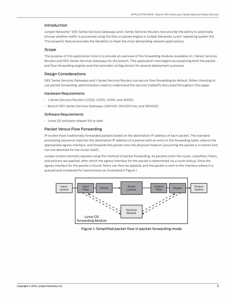
Juniper routers normally operate using this method of packet forwarding. As packets enter the router, classifiers, filters,
and policers are applied, after which the egress interface for the packet is determined via a route lookup. Once the
egress interface for the packet is found, filters can then be applied, and the packet is sent to the interface where it is
queued and scheduled for transmission as illustrated in Figure 1.
Figure 1: Simplified packet flow in packet-forwarding mode
InputQueue
InputFilter
PolicerRoute
Lookup
ServicesModule
Junos OSforwarding Module
OutputFilter
ShaperOutputQueue
4 Copyright © 2010, Juniper Networks, Inc.
APPLICATION NOTE - Branch SrX Series and J Series Selective Packet Services
This processing mode does not require any information about either previous or subsequent packets that belong to a
given connection. Each packet is individually processed, and any decision to allow or deny traffic is packet specific. Any
additional services such as firewall filtering, Network Address Translation (NAT), and IPsec result in increased overhead.
Firewalls and security devices take a session-based processing approach. Session-based or flow-mode processing
leverages session state to minimize packet-by-packet decision making, and this improves the overall performance of
SrX Series Services Gateways for the branch. In flow mode, traffic is inspected at the transport level using a five-tuple
match of source and destination addresses, source and destination ports (when applicable), and protocol with the source
and destination zones to determine if the packet belongs to a new or existing session. For any new traffic, route and policy
lookups are performed. After lookups, all subsequent packets in the session are “fast path” processed using the action
determined by the first packet. As long as future traffic matches the initial session, the processing continues unabated.
The main advantage of packet forwarding is that routers do not have to keep track of all session information or analyze
how sessions are established, which optimizes packet processing. In some cases, the forwarding path is implemented
using ASICs to achieve high, deterministic performance. Firewalls, on the other hand, only use ASICs to accelerate the
packet forwarding once a session is established.
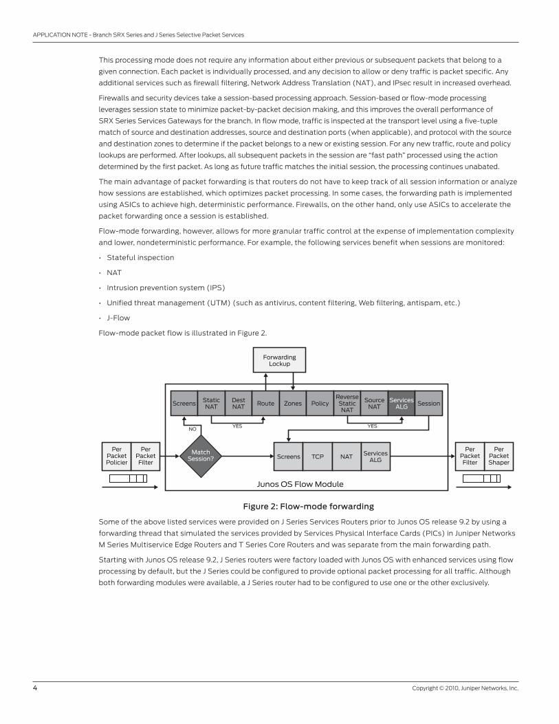
Flow-mode forwarding, however, allows for more granular traffic control at the expense of implementation complexity
and lower, nondeterministic performance. For example, the following services benefit when sessions are monitored:
• Stateful inspection
• NAT
• Intrusion prevention system (IPS)
• Unified threat management (UTM) (such as antivirus, content filtering, Web filtering, antispam, etc.)
• J-Flow
Flow-mode packet flow is illustrated in Figure 2.
Figure 2: Flow-mode forwarding
Some of the above listed services were provided on J Series Services routers prior to Junos OS release 9.2 by using a
forwarding thread that simulated the services provided by Services Physical Interface Cards (PICs) in Juniper Networks
M Series Multiservice Edge routers and T Series Core routers and was separate from the main forwarding path.
Starting with Junos OS release 9.2, J Series routers were factory loaded with Junos OS with enhanced services using flow
processing by default, but the J Series could be configured to provide optional packet processing for all traffic. Although
both forwarding modules were available, a J Series router had to be configured to use one or the other exclusively.
Junos OS Flow Module
Screens
NOYES YES
PerPacketPolicier
PerPacketFilter
PerPacketFilter
PerPacketShaper
Screens TCP NAT ServicesALG
StaticNAT
ForwardingLockup
DestNAT Route Zones Policy
ReverseStaticNAT
SourceNAT
ServicesALG
MatchSession?
Session
Copyright © 2010, Juniper Networks, Inc. 5
APPLICATION NOTE - Branch SrX Series and J Series Selective Packet Services
Traffic is processed by the packet-based forwarding module providing all of the following services:
• routing
• Quality of service (QoS)
• Link fragmentation and interleaving (LFI)
• Generic routing encapsulation (GrE) and IP over IP (IP-IP) tunneling (no fragmentation and reassembly)
• L2 switching
• MPLS
• IPv6
• Compressed real-Time Transport Protocol (CrTP)
The flow-based forwarding module was able to provide all of the above and also deliver the following services:
• Stateful inspection firewall (including screens)
• NAT
• IPsec
• J-Flow
• Intrusion detection and prevention
• UTM
• GrE fragmentation and reassembly
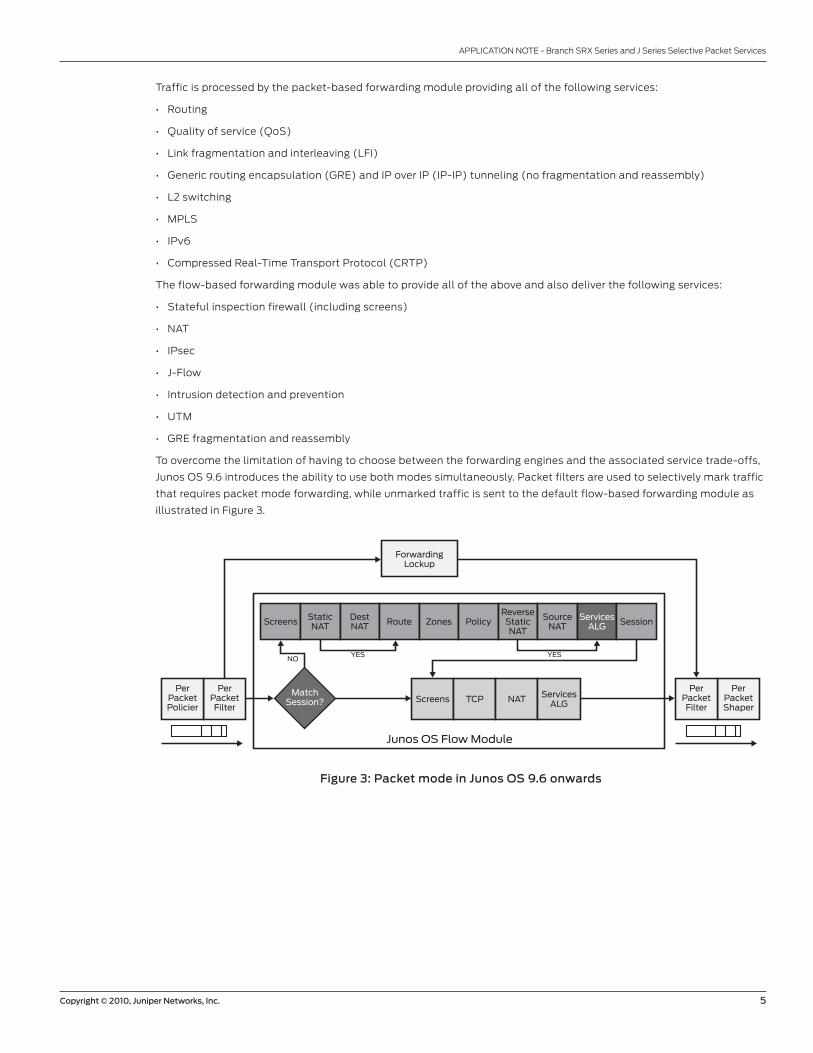
To overcome the limitation of having to choose between the forwarding engines and the associated service trade-offs,
Junos OS 9.6 introduces the ability to use both modes simultaneously. Packet filters are used to selectively mark traffic
that requires packet mode forwarding, while unmarked traffic is sent to the default flow-based forwarding module as
illustrated in Figure 3.
Figure 3: Packet mode in Junos OS 9.6 onwards
Junos OS Flow Module
Screens
NOYES YES
PerPacketPolicier
PerPacketFilter
PerPacketFilter
PerPacketShaper
Screens TCP NAT ServicesALG
StaticNAT
ForwardingLockup
DestNAT Route Zones Policy
ReverseStaticNAT
SourceNAT
ServicesALG
MatchSession?
Session
6 Copyright © 2010, Juniper Networks, Inc.
APPLICATION NOTE - Branch SrX Series and J Series Selective Packet Services
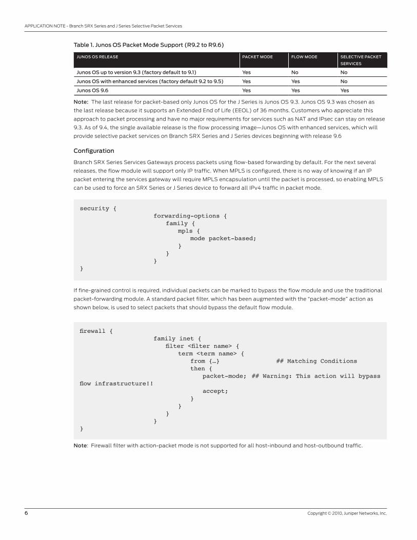
Table 1. Junos OS Packet Mode Support (R9.2 to R9.6)
JuNOS OS ReLeaSe PaCkeT MODe FLOw MODe SeLeCTIVe PaCkeT
SeRVICeS
Junos OS up to version 9.3 (factory default to 9.1) Yes No No
Junos OS with enhanced services (factory default 9.2 to 9.5) Yes Yes No
Junos OS 9.6 Yes Yes Yes
Note: The last release for packet-based only Junos OS for the J Series is Junos OS 9.3. Junos OS 9.3 was chosen as
the last release because it supports an Extended End of Life (EEOL) of 36 months. Customers who appreciate this
approach to packet processing and have no major requirements for services such as NAT and IPsec can stay on release
9.3. As of 9.4, the single available release is the flow processing image—Junos OS with enhanced services, which will
provide selective packet services on Branch SrX Series and J Series devices beginning with release 9.6
Configuration
Branch SrX Series Services Gateways process packets using flow-based forwarding by default. For the next several
releases, the flow module will support only IP traffic. When MPLS is configured, there is no way of knowing if an IP
packet entering the services gateway will require MPLS encapsulation until the packet is processed, so enabling MPLS
can be used to force an SrX Series or J Series device to forward all IPv4 traffic in packet mode.
security { forwarding-options { family { mpls { mode packet-based; } } }}
If fine-grained control is required, individual packets can be marked to bypass the flow module and use the traditional
packet-forwarding module. A standard packet filter, which has been augmented with the “packet-mode” action as
shown below, is used to select packets that should bypass the default flow module.
firewall { family inet { filter <filter name> { term <term name> { from {…} ## Matching Conditions then { packet-mode; ## Warning: This action will bypass flow infrastructure!! accept; } } } }}
Note: Firewall filter with action-packet mode is not supported for all host-inbound and host-outbound traffic.
Copyright © 2010, Juniper Networks, Inc. 7
APPLICATION NOTE - Branch SrX Series and J Series Selective Packet Services
Description and Deployment Scenarios
In the following section, we will discuss several common deployment scenarios and provide the associated configurations.
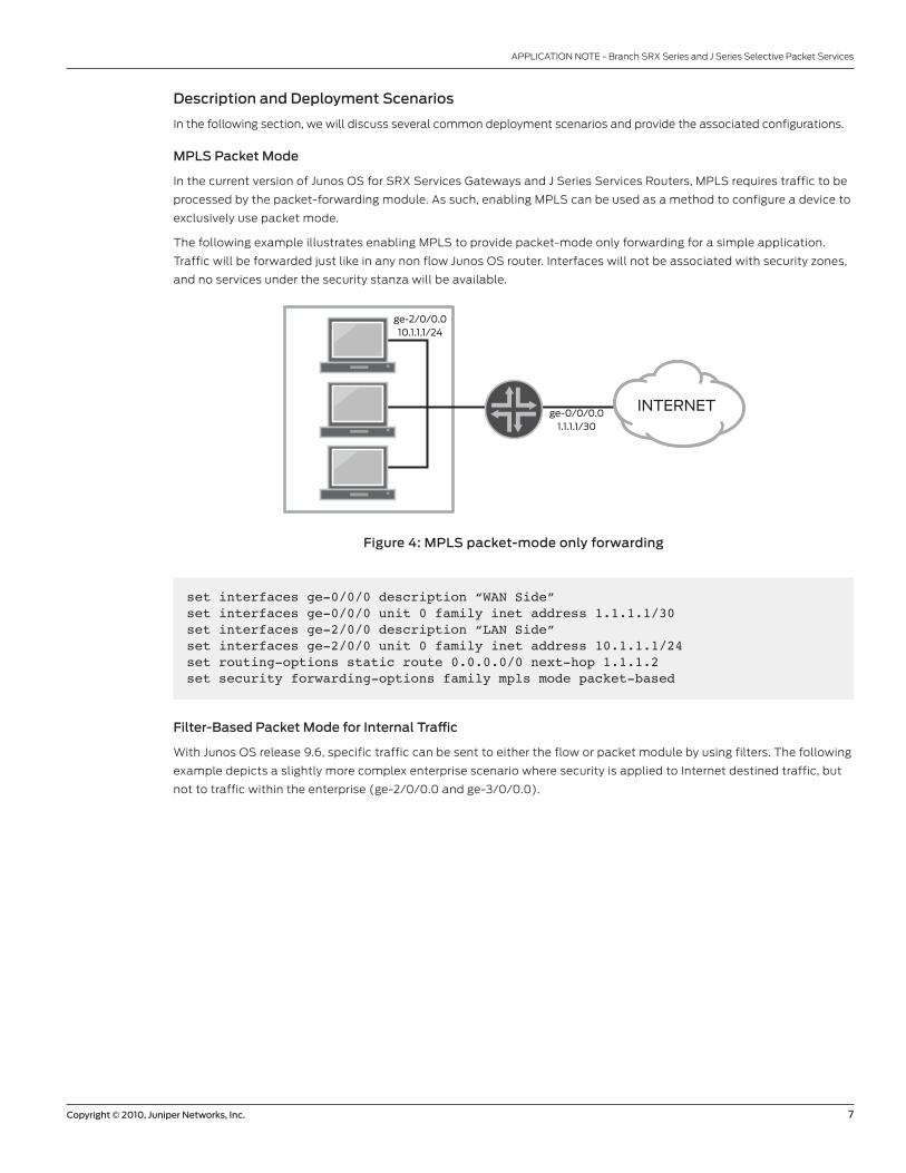
MPLS Packet Mode
In the current version of Junos OS for SrX Services Gateways and J Series Services routers, MPLS requires traffic to be
processed by the packet-forwarding module. As such, enabling MPLS can be used as a method to configure a device to
exclusively use packet mode.
The following example illustrates enabling MPLS to provide packet-mode only forwarding for a simple application.
Traffic will be forwarded just like in any non flow Junos OS router. Interfaces will not be associated with security zones,
and no services under the security stanza will be available.
Figure 4: MPLS packet-mode only forwarding
ge-2/0/0.010.1.1.1/24
ge-0/0/0.01.1.1.1/30
INTERNET
set interfaces ge-0/0/0 description “WAN Side”set interfaces ge-0/0/0 unit 0 family inet address 1.1.1.1/30set interfaces ge-2/0/0 description “LAN Side”set interfaces ge-2/0/0 unit 0 family inet address 10.1.1.1/24set routing-options static route 0.0.0.0/0 next-hop 1.1.1.2set security forwarding-options family mpls mode packet-based
Filter-Based Packet Mode for Internal Traffic
With Junos OS release 9.6, specific traffic can be sent to either the flow or packet module by using filters. The following
example depicts a slightly more complex enterprise scenario where security is applied to Internet destined traffic, but
not to traffic within the enterprise (ge-2/0/0.0 and ge-3/0/0.0).
8 Copyright © 2010, Juniper Networks, Inc.
APPLICATION NOTE - Branch SrX Series and J Series Selective Packet Services
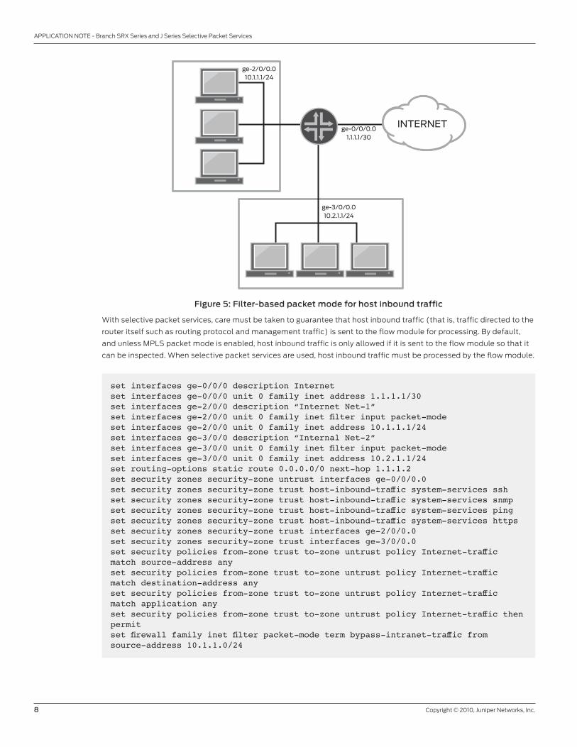
Figure 5: Filter-based packet mode for host inbound traffic
With selective packet services, care must be taken to guarantee that host inbound traffic (that is, traffic directed to the
router itself such as routing protocol and management traffic) is sent to the flow module for processing. By default,
and unless MPLS packet mode is enabled, host inbound traffic is only allowed if it is sent to the flow module so that it
can be inspected. When selective packet services are used, host inbound traffic must be processed by the flow module.
ge-2/0/0.010.1.1.1/24
ge-0/0/0.01.1.1.1/30
ge-3/0/0.010.2.1.1/24
INTERNET
set interfaces ge-0/0/0 description Internetset interfaces ge-0/0/0 unit 0 family inet address 1.1.1.1/30set interfaces ge-2/0/0 description “Internet Net-1”set interfaces ge-2/0/0 unit 0 family inet filter input packet-modeset interfaces ge-2/0/0 unit 0 family inet address 10.1.1.1/24set interfaces ge-3/0/0 description “Internal Net-2”set interfaces ge-3/0/0 unit 0 family inet filter input packet-modeset interfaces ge-3/0/0 unit 0 family inet address 10.2.1.1/24set routing-options static route 0.0.0.0/0 next-hop 1.1.1.2set security zones security-zone untrust interfaces ge-0/0/0.0set security zones security-zone trust host-inbound-traffic system-services sshset security zones security-zone trust host-inbound-traffic system-services snmpset security zones security-zone trust host-inbound-traffic system-services pingset security zones security-zone trust host-inbound-traffic system-services httpsset security zones security-zone trust interfaces ge-2/0/0.0set security zones security-zone trust interfaces ge-3/0/0.0set security policies from-zone trust to-zone untrust policy Internet-traffic match source-address anyset security policies from-zone trust to-zone untrust policy Internet-traffic match destination-address anyset security policies from-zone trust to-zone untrust policy Internet-traffic match application anyset security policies from-zone trust to-zone untrust policy Internet-traffic then permitset firewall family inet filter packet-mode term bypass-intranet-traffic from source-address 10.1.1.0/24
Copyright © 2010, Juniper Networks, Inc. 9
APPLICATION NOTE - Branch SrX Series and J Series Selective Packet Services
set firewall family inet filter packet-mode term bypass-intranet-traffic from destination-address 10.2.1.0/24set firewall family inet filter packet-mode term bypass-intranet-traffic then packet-modeset firewall family inet filter packet-mode term bypass-intranet-traffic then acceptset firewall family inet filter packet-mode term bypass-intranet-traffic-rev from source-address 10.2.1.0/24set firewall family inet filter packet-mode term bypass-intranet-traffic-rev from destination-address 10.1.1.0/24set firewall family inet filter packet-mode term bypass-intranet-traffic-rev then packet-modeset firewall family inet filter packet-mode term bypass-intranet-traffic-rev then acceptset firewall family inet filter packet-mode term accept-all then accept
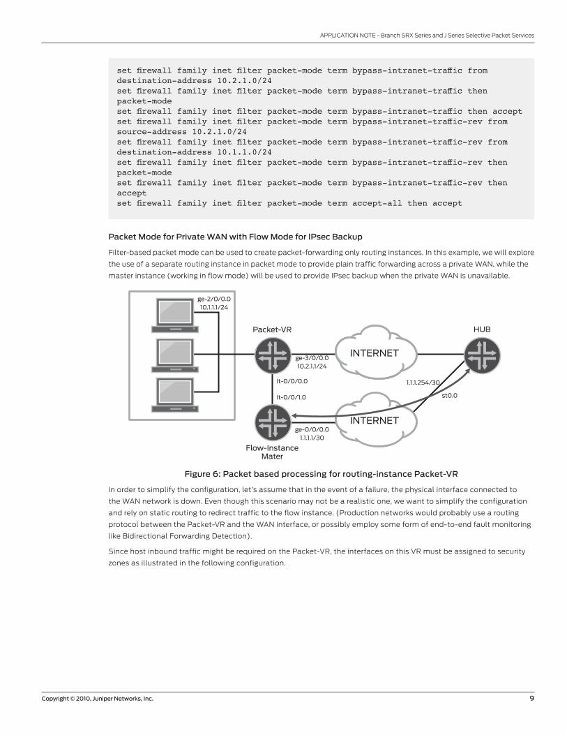
Packet Mode for Private waN with Flow Mode for IPsec Backup
Filter-based packet mode can be used to create packet-forwarding only routing instances. In this example, we will explore
the use of a separate routing instance in packet mode to provide plain traffic forwarding across a private WAN, while the
master instance (working in flow mode) will be used to provide IPsec backup when the private WAN is unavailable.
Figure 6: Packet based processing for routing-instance Packet-VR
In order to simplify the configuration, let’s assume that in the event of a failure, the physical interface connected to
the WAN network is down. Even though this scenario may not be a realistic one, we want to simplify the configuration
and rely on static routing to redirect traffic to the flow instance. (Production networks would probably use a routing
protocol between the Packet-vr and the WAN interface, or possibly employ some form of end-to-end fault monitoring
like Bidirectional Forwarding detection).
Since host inbound traffic might be required on the Packet-vr, the interfaces on this vr must be assigned to security
zones as illustrated in the following configuration.
ge-2/0/0.010.1.1.1/24
ge-3/0/0.010.2.1.1/24
ge-0/0/0.01.1.1.1/30
It-0/0/0.0
It-0/0/1.0
1.1.1.254/30
st0.0
HUB
Flow-InstanceMater
Packet-VR
INTERNET
INTERNET

10 Copyright © 2010, Juniper Networks, Inc.
APPLICATION NOTE - Branch SrX Series and J Series Selective Packet Services
set interfaces ge-0/0/0 description Internetset interfaces ge-0/0/0 unit 0 family inet address 1.1.1.1/30set interfaces lt-0/0/0 unit 0 description “PTP Interface connecting the Packet-VR to the Master Instance (in flow mode)”set interfaces lt-0/0/0 unit 0 encapsulation frame-relayset interfaces lt-0/0/0 unit 0 point-to-pointset interfaces lt-0/0/0 unit 0 dlci 30set interfaces lt-0/0/0 unit 0 peer-unit 1set interfaces lt-0/0/0 unit 0 family inet filter input packet-modeset interfaces lt-0/0/0 unit 1 description “PTP Interface connecting the Master Instance (in flow mode) to the Packet-VR”set interfaces lt-0/0/0 unit 1 encapsulation frame-relayset interfaces lt-0/0/0 unit 1 dlci 30set interfaces lt-0/0/0 unit 1 peer-unit 0set interfaces lt-0/0/0 unit 1 family inetset interfaces ge-2/0/0 description “LAN Network”set interfaces ge-2/0/0 unit 0 family inet filter input packet-modeset interfaces ge-2/0/0 unit 0 family inet address 10.1.1.1/24set interfaces ge-3/0/0 description “WAN Network”set interfaces ge-3/0/0 unit 0 family inet filter input packet-modeset interfaces ge-3/0/0 unit 0 family inet address 10.2.1.1/24set interfaces st0 unit 0 family inet
## This is the address of the remote IPsec gateway, which is routed to the default gateway on the Internetset routing-options static route 1.1.1.254/32 next-hop 1.1.1.2
set routing-options static route 10.1.1.0/24 next-hop lt-0/0/0.1
## Every packet received by the flow routing instance is sent to the IPsec tunnelset routing-options static route 0.0.0.0/0 next-hop st0.0
set security ike policy preshared mode mainset security ike policy preshared proposal-set standardset security ike policy preshared pre-shared-key ascii-text “$9$gkaGiP5FApBk.pBIEeK4aZ”set security ike gateway SRX210-1 ike-policy presharedset security ike gateway SRX210-1 address 1.1.1.254set security ike gateway SRX210-1 external-interface ge-0/0/0.0set security ipsec policy standard proposal-set standardset security ipsec vpn SRX210-1 bind-interface st0.0set security ipsec vpn SRX210-1 ike gateway SRX210-1set security ipsec vpn SRX210-1 ike ipsec-policy standardset security ipsec vpn SRX210-1 establish-tunnels immediatelyset security zones security-zone untrust interfaces ge-0/0/0.0set security zones security-zone trust host-inbound-traffic system-services sshset security zones security-zone trust host-inbound-traffic system-services snmpset security zones security-zone trust host-inbound-traffic system-services pingset security zones security-zone trust host-inbound-traffic system-services httpsset security zones security-zone trust interfaces ge-2/0/0.0set security zones security-zone trust interfaces ge-3/0/0.0set security zones security-zone trust-flow interfaces lt-0/0/0.1set security zones security-zone vpn interfaces st0.0
## Traffic policies control only the flow of traffic through the Flow instance## therefore the only traffic allowed is going to be from the trust zone on the## flow instance (named trust-flow) to the vpn zone bound to the IPsec interfaceset security policies from-zone trust-flow to-zone vpn policy allow-intranet-
Copyright © 2010, Juniper Networks, Inc. 11
APPLICATION NOTE - Branch SrX Series and J Series Selective Packet Services
traffic match source-address anyset security policies from-zone trust-flow to-zone vpn policy allow-intranet-traffic match destination-address anyset security policies from-zone trust-flow to-zone vpn policy allow-intranet-traffic match application anyset security policies from-zone trust-flow to-zone vpn policy allow-intranet-traffic then permit
set firewall family inet filter packet-mode term host-inbound from destination-address 10.2.1.1/32set firewall family inet filter packet-mode term host-inbound from destination-address 10.1.1.1/32set firewall family inet filter packet-mode term host-inbound then acceptset firewall family inet filter packet-mode term packet-mode-rest then packet-modeset firewall family inet filter packet-mode term packet-mode-rest then acceptset routing-instances Packet-VR instance-type virtual-routerset routing-instances Packet-VR interface lt-0/0/0.0set routing-instances Packet-VR interface ge-2/0/0.0set routing-instances Packet-VR interface ge-3/0/0.0
## This is the address of the gateway in the WANset routing-instances Packet-VR routing-options static route 0.0.0.0/0 next-hop 10.2.1.90
## the default also points to the lt-interface connecting to the flow instance with a lower metricset routing-instances Packet-VR routing-options static route 0.0.0.0/0 qualified-next-hop lt-0/0/0.0 metric 100
The IPsec portion of the configuration was added for completeness. readers not familiar with IPsec configuration
should consult the Junos OS documentation, as IPsec is outside the scope of this document. however, note that
interface st0.0 belongs to the flow instance and connects to remote hub using an IPsec tunnel through the Internet.
L3 MPLS VPN with Services
In this last example, we will demonstrate how filter-based packet forwarding can be used to provide security services
to a vPN routing and forwarding table (vrF) instance terminating a L3 MPLS-based vPN.
We will start by creating a simple L3 MPLS vPN using MPLS packet mode and then add flow-based services to the vPN.
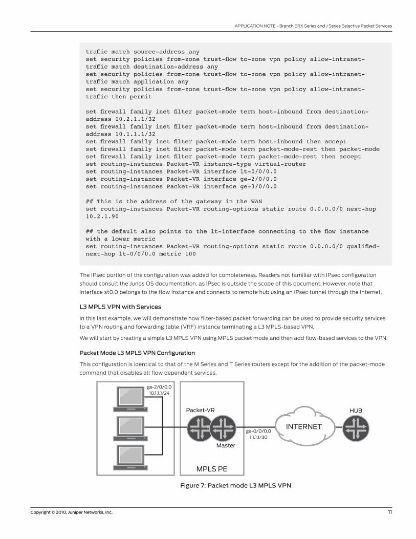
Packet Mode L3 MPLS VPN Configuration
This configuration is identical to that of the M Series and T Series routers except for the addition of the packet-mode
command that disables all flow dependent services.
Figure 7: Packet mode L3 MPLS VPN
ge-2/0/0.010.1.1.1/24
ge-0/0/0.01.1.1.1/30
HUBPacket-VR
Master
MPLS PE
INTERNET
12 Copyright © 2010, Juniper Networks, Inc.
APPLICATION NOTE - Branch SrX Series and J Series Selective Packet Services
set interfaces ge-0/0/0 unit 0 description “Connection to MPLS Core”set interfaces ge-0/0/0 unit 0 family inet address 1.1.1.1/30set interfaces ge-0/0/0 unit 0 family mplsset interfaces ge-2/0/0 description “Cust-1 LAN”set interfaces ge-2/0/0 unit 0 family inet address 10.1.1.1/24set interfaces lo0 unit 0 family inet address 10.255.255.253/32set routing-options static route 0.0.0.0/0 next-hop 1.1.1.2set protocols mpls interface ge-0/0/0.0set protocols mpls interface lo0.0set protocols bgp local-address 10.255.255.253set protocols bgp local-as 65100set protocols bgp group mpls-vpn type internalset protocols bgp group mpls-vpn neighbor 10.255.255.254 family inet-vpn unicastset protocols bgp group mpls-vpn neighbor 10.255.255.254 peer-as 65100set protocols ospf area 0.0.0.0 interface ge-0/0/0.0set protocols ospf area 0.0.0.0 interface lo0.0 passiveset protocols ldp interface ge-0/0/0.0set security forwarding-options family mpls mode packet-basedset routing-instances Cust1-Packet-VRF instance-type vrfset routing-instances Cust1-Packet-VRF interface ge-2/0/0.0set routing-instances Cust1-Packet-VRF route-distinguisher 65100:1set routing-instances Cust1-Packet-VRF vrf-target target:65100:1set routing-instances Cust1-Packet-VRF vrf-table-label
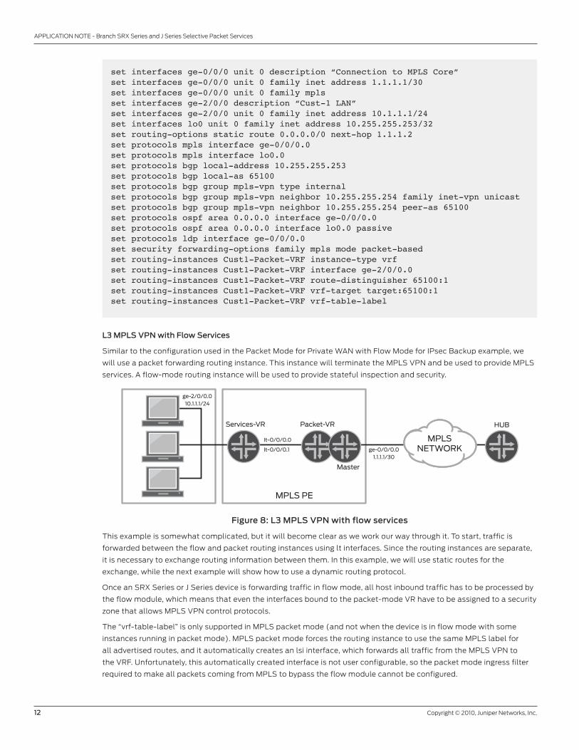
L3 MPLS VPN with Flow Services
Similar to the configuration used in the Packet Mode for Private WAN with Flow Mode for IPsec Backup example, we
will use a packet forwarding routing instance. This instance will terminate the MPLS vPN and be used to provide MPLS
services. A flow-mode routing instance will be used to provide stateful inspection and security.
Figure 8: L3 MPLS VPN with flow services
This example is somewhat complicated, but it will become clear as we work our way through it. To start, traffic is
forwarded between the flow and packet routing instances using lt interfaces. Since the routing instances are separate,
it is necessary to exchange routing information between them. In this example, we will use static routes for the
exchange, while the next example will show how to use a dynamic routing protocol.
Once an SrX Series or J Series device is forwarding traffic in flow mode, all host inbound traffic has to be processed by
the flow module, which means that even the interfaces bound to the packet-mode vr have to be assigned to a security
zone that allows MPLS vPN control protocols.
The “vrf-table-label” is only supported in MPLS packet mode (and not when the device is in flow mode with some
instances running in packet mode). MPLS packet mode forces the routing instance to use the same MPLS label for
all advertised routes, and it automatically creates an lsi interface, which forwards all traffic from the MPLS vPN to
the vrF. Unfortunately, this automatically created interface is not user configurable, so the packet mode ingress filter
required to make all packets coming from MPLS to bypass the flow module cannot be configured.
ge-2/0/0.010.1.1.1/24
ge-0/0/0.01.1.1.1/30
It-0/0/0.1
It-0/0/0.0
HUBPacket-VR
Master
MPLS PE
Services-VR
MPLSNETWORK
Copyright © 2010, Juniper Networks, Inc. 13
APPLICATION NOTE - Branch SrX Series and J Series Selective Packet Services
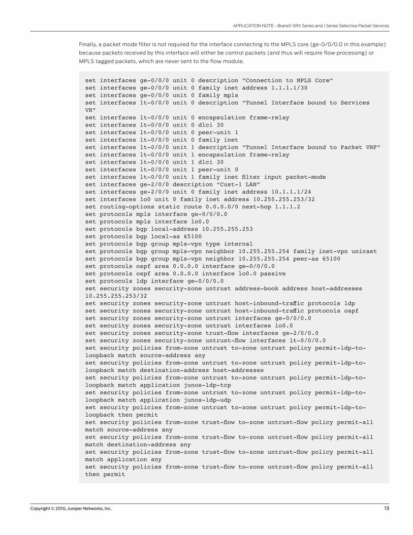
Finally, a packet mode filter is not required for the interface connecting to the MPLS core (ge-0/0/0.0 in this example)
because packets received by this interface will either be control packets (and thus will require flow processing) or
MPLS tagged packets, which are never sent to the flow module.
set interfaces ge-0/0/0 unit 0 description “Connection to MPLS Core”set interfaces ge-0/0/0 unit 0 family inet address 1.1.1.1/30set interfaces ge-0/0/0 unit 0 family mplsset interfaces lt-0/0/0 unit 0 description “Tunnel Interface bound to Services VR”set interfaces lt-0/0/0 unit 0 encapsulation frame-relayset interfaces lt-0/0/0 unit 0 dlci 30set interfaces lt-0/0/0 unit 0 peer-unit 1set interfaces lt-0/0/0 unit 0 family inetset interfaces lt-0/0/0 unit 1 description “Tunnel Interface bound to Packet VRF”set interfaces lt-0/0/0 unit 1 encapsulation frame-relayset interfaces lt-0/0/0 unit 1 dlci 30set interfaces lt-0/0/0 unit 1 peer-unit 0set interfaces lt-0/0/0 unit 1 family inet filter input packet-modeset interfaces ge-2/0/0 description “Cust-1 LAN”set interfaces ge-2/0/0 unit 0 family inet address 10.1.1.1/24set interfaces lo0 unit 0 family inet address 10.255.255.253/32set routing-options static route 0.0.0.0/0 next-hop 1.1.1.2set protocols mpls interface ge-0/0/0.0set protocols mpls interface lo0.0set protocols bgp local-address 10.255.255.253set protocols bgp local-as 65100set protocols bgp group mpls-vpn type internalset protocols bgp group mpls-vpn neighbor 10.255.255.254 family inet-vpn unicastset protocols bgp group mpls-vpn neighbor 10.255.255.254 peer-as 65100set protocols ospf area 0.0.0.0 interface ge-0/0/0.0set protocols ospf area 0.0.0.0 interface lo0.0 passiveset protocols ldp interface ge-0/0/0.0set security zones security-zone untrust address-book address host-addresses 10.255.255.253/32set security zones security-zone untrust host-inbound-traffic protocols ldpset security zones security-zone untrust host-inbound-traffic protocols ospfset security zones security-zone untrust interfaces ge-0/0/0.0set security zones security-zone untrust interfaces lo0.0set security zones security-zone trust-flow interfaces ge-2/0/0.0set security zones security-zone untrust-flow interfaces lt-0/0/0.0set security policies from-zone untrust to-zone untrust policy permit-ldp-to-loopback match source-address anyset security policies from-zone untrust to-zone untrust policy permit-ldp-to-loopback match destination-address host-addressesset security policies from-zone untrust to-zone untrust policy permit-ldp-to-loopback match application junos-ldp-tcpset security policies from-zone untrust to-zone untrust policy permit-ldp-to-loopback match application junos-ldp-udpset security policies from-zone untrust to-zone untrust policy permit-ldp-to-loopback then permitset security policies from-zone trust-flow to-zone untrust-flow policy permit-all match source-address anyset security policies from-zone trust-flow to-zone untrust-flow policy permit-all match destination-address anyset security policies from-zone trust-flow to-zone untrust-flow policy permit-all match application anyset security policies from-zone trust-flow to-zone untrust-flow policy permit-all then permit
14 Copyright © 2010, Juniper Networks, Inc.
APPLICATION NOTE - Branch SrX Series and J Series Selective Packet Services
set firewall family inet filter packet-mode term bypass-all then packet-modeset firewall family inet filter packet-mode term bypass-all then acceptset routing-instances Cust1-Packet-VRF instance-type vrfset routing-instances Cust1-Packet-VRF interface lt-0/0/0.1set routing-instances Cust1-Packet-VRF route-distinguisher 65100:1set routing-instances Cust1-Packet-VRF vrf-target target:65100:1set routing-instances Cust1-Packet-VRF routing-options static route 10.1.1.0/24 next-hop lt-0/0/0.1set routing-instances Cust1-Services-VR instance-type virtual-routerset routing-instances Cust1-Services-VR interface lt-0/0/0.0set routing-instances Cust1-Services-VR interface ge-2/0/0.0set routing-instances Cust1-Services-VR routing-options static route 0.0.0.0/0 next-hop lt-0/0/0.0
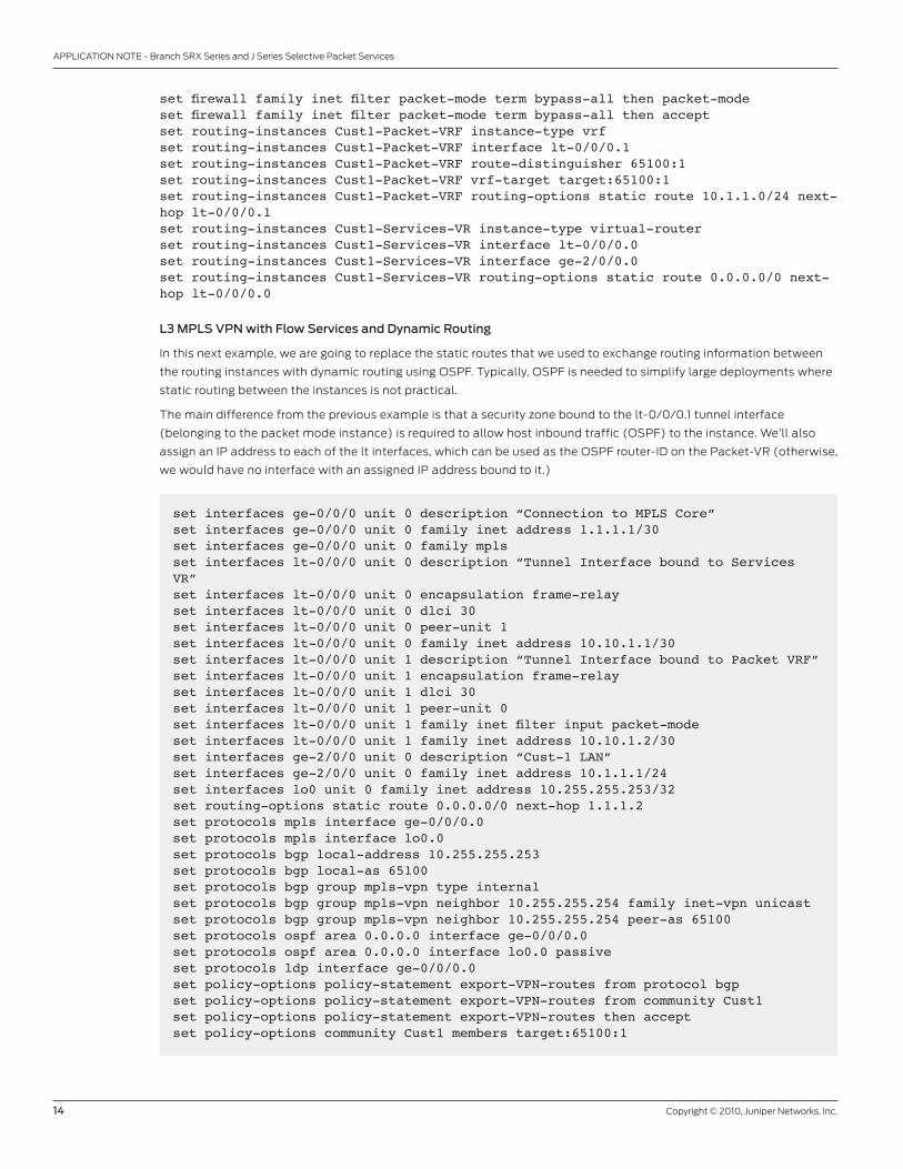
L3 MPLS VPN with Flow Services and Dynamic Routing
In this next example, we are going to replace the static routes that we used to exchange routing information between
the routing instances with dynamic routing using OSPF. Typically, OSPF is needed to simplify large deployments where
static routing between the instances is not practical.
The main difference from the previous example is that a security zone bound to the lt-0/0/0.1 tunnel interface
(belonging to the packet mode instance) is required to allow host inbound traffic (OSPF) to the instance. We’ll also
assign an IP address to each of the lt interfaces, which can be used as the OSPF router-Id on the Packet-vr (otherwise,
we would have no interface with an assigned IP address bound to it.)
set interfaces ge-0/0/0 unit 0 description “Connection to MPLS Core”set interfaces ge-0/0/0 unit 0 family inet address 1.1.1.1/30set interfaces ge-0/0/0 unit 0 family mplsset interfaces lt-0/0/0 unit 0 description “Tunnel Interface bound to Services VR”set interfaces lt-0/0/0 unit 0 encapsulation frame-relayset interfaces lt-0/0/0 unit 0 dlci 30set interfaces lt-0/0/0 unit 0 peer-unit 1set interfaces lt-0/0/0 unit 0 family inet address 10.10.1.1/30set interfaces lt-0/0/0 unit 1 description “Tunnel Interface bound to Packet VRF”set interfaces lt-0/0/0 unit 1 encapsulation frame-relayset interfaces lt-0/0/0 unit 1 dlci 30set interfaces lt-0/0/0 unit 1 peer-unit 0set interfaces lt-0/0/0 unit 1 family inet filter input packet-modeset interfaces lt-0/0/0 unit 1 family inet address 10.10.1.2/30set interfaces ge-2/0/0 unit 0 description “Cust-1 LAN”set interfaces ge-2/0/0 unit 0 family inet address 10.1.1.1/24set interfaces lo0 unit 0 family inet address 10.255.255.253/32set routing-options static route 0.0.0.0/0 next-hop 1.1.1.2set protocols mpls interface ge-0/0/0.0set protocols mpls interface lo0.0set protocols bgp local-address 10.255.255.253set protocols bgp local-as 65100set protocols bgp group mpls-vpn type internalset protocols bgp group mpls-vpn neighbor 10.255.255.254 family inet-vpn unicastset protocols bgp group mpls-vpn neighbor 10.255.255.254 peer-as 65100set protocols ospf area 0.0.0.0 interface ge-0/0/0.0set protocols ospf area 0.0.0.0 interface lo0.0 passiveset protocols ldp interface ge-0/0/0.0set policy-options policy-statement export-VPN-routes from protocol bgpset policy-options policy-statement export-VPN-routes from community Cust1set policy-options policy-statement export-VPN-routes then acceptset policy-options community Cust1 members target:65100:1

Copyright © 2010, Juniper Networks, Inc. 15
APPLICATION NOTE - Branch SrX Series and J Series Selective Packet Services
set security zones security-zone untrust address-book address host-addresses 10.255.255.253/32set security zones security-zone untrust host-inbound-traffic protocols ldpset security zones security-zone untrust host-inbound-traffic protocols ospfset security zones security-zone untrust interfaces ge-0/0/0.0set security zones security-zone untrust interfaces lo0.0set security zones security-zone trust-flow interfaces ge-2/0/0.0set security zones security-zone untrust-flow host-inbound-traffic protocols ospfset security zones security-zone untrust-flow interfaces lt-0/0/0.0set security zones security-zone host-inbound-Cust1-Packet host-inbound-traffic protocols ospfset security zones security-zone host-inbound-Cust1-Packet interfaces lt-0/0/0.1set security policies from-zone untrust to-zone untrust policy permit-ldp-to-loopback match source-address anyset security policies from-zone untrust to-zone untrust policy permit-ldp-to-loopback match destination-address host-addressesset security policies from-zone untrust to-zone untrust policy permit-ldp-to-loopback match application junos-ldp-tcpset security policies from-zone untrust to-zone untrust policy permit-ldp-to-loopback match application junos-ldp-udpset security policies from-zone untrust to-zone untrust policy permit-ldp-to-loopback then permitset security policies from-zone trust-flow to-zone untrust-flow policy permit-all match source-address anyset security policies from-zone trust-flow to-zone untrust-flow policy permit-all match destination-address anyset security policies from-zone trust-flow to-zone untrust-flow policy permit-all match application anyset security policies from-zone trust-flow to-zone untrust-flow policy permit-all then permitset firewall family inet filter packet-mode term ospf-to-flow from protocol ospfset firewall family inet filter packet-mode term ospf-to-flow then acceptset firewall family inet filter packet-mode term bypass-all then packet-modeset firewall family inet filter packet-mode term bypass-all then acceptset routing-instances Cust1-Packet-VRF instance-type vrfset routing-instances Cust1-Packet-VRF interface lt-0/0/0.1set routing-instances Cust1-Packet-VRF route-distinguisher 65100:1set routing-instances Cust1-Packet-VRF vrf-target target:65100:1set routing-instances Cust1-Packet-VRF protocols ospf export export-VPN-routesset routing-instances Cust1-Packet-VRF protocols ospf area 0.0.0.0 interface lt-0/0/0.1set routing-instances Cust1-Services-VR instance-type virtual-routerset routing-instances Cust1-Services-VR interface lt-0/0/0.0set routing-instances Cust1-Services-VR interface ge-2/0/0.0set routing-instances Cust1-Services-VR protocols ospf area 0.0.0.0 interface lt-0/0/0.0set routing-instances Cust1-Services-VR protocols ospf area 0.0.0.0 interface ge-2/0/0.0 passive
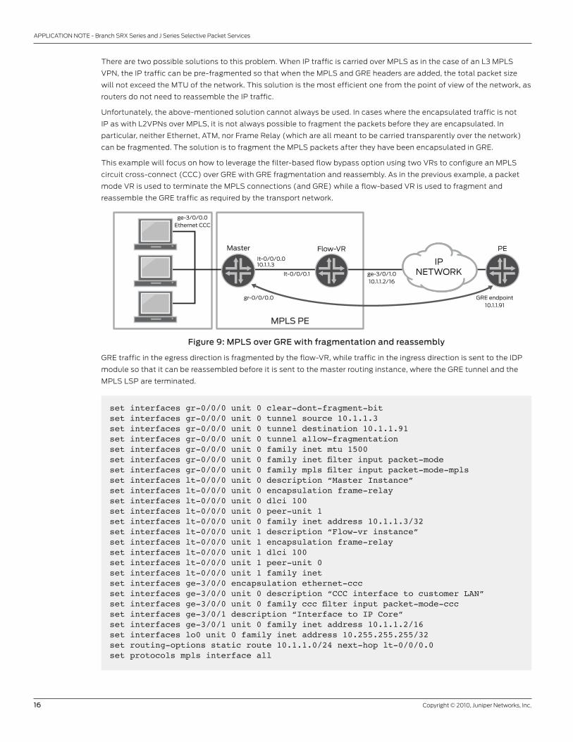
MPLSoGRe with GRe Fragmentation and Reassembly
A common challenge associated with the use of MPLS over generic routing encapsulation (MPLSoGrE) is the need to
fragment GrE packets. When GrE is used to transport MPLS packets over an Ethernet-based transport network, the
transport network often supports a maximum transmission unit (MTU) of 1,500 bytes. Because of the overhead required
to encapsulate MPLS packets in GrE, it is possible for the encapsulated packet size to exceed the MTU of the network.
16 Copyright © 2010, Juniper Networks, Inc.
APPLICATION NOTE - Branch SrX Series and J Series Selective Packet Services
There are two possible solutions to this problem. When IP traffic is carried over MPLS as in the case of an L3 MPLS
vPN, the IP traffic can be pre-fragmented so that when the MPLS and GrE headers are added, the total packet size
will not exceed the MTU of the network. This solution is the most efficient one from the point of view of the network, as
routers do not need to reassemble the IP traffic.
Unfortunately, the above-mentioned solution cannot always be used. In cases where the encapsulated traffic is not
IP as with L2vPNs over MPLS, it is not always possible to fragment the packets before they are encapsulated. In
particular, neither Ethernet, ATM, nor Frame relay (which are all meant to be carried transparently over the network)
can be fragmented. The solution is to fragment the MPLS packets after they have been encapsulated in GrE.
This example will focus on how to leverage the filter-based flow bypass option using two vrs to configure an MPLS
circuit cross-connect (CCC) over GrE with GrE fragmentation and reassembly. As in the previous example, a packet
mode vr is used to terminate the MPLS connections (and GrE) while a flow-based vr is used to fragment and
reassemble the GrE traffic as required by the transport network.
Figure 9: MPLS over GRe with fragmentation and reassembly
GrE traffic in the egress direction is fragmented by the flow-vr, while traffic in the ingress direction is sent to the IdP
module so that it can be reassembled before it is sent to the master routing instance, where the GrE tunnel and the
MPLS LSP are terminated.
ge-3/0/0.0Ethernet CCC
ge-3/0/1.010.1.1.2/16
It-0/0/0.1
gr-0/0/0.0 GRE endpoint10.1.1.91
It-0/0/0.010.1.1.3
PEFlow-VR
MPLS PE
Master
IPNETWORK
set interfaces gr-0/0/0 unit 0 clear-dont-fragment-bitset interfaces gr-0/0/0 unit 0 tunnel source 10.1.1.3set interfaces gr-0/0/0 unit 0 tunnel destination 10.1.1.91set interfaces gr-0/0/0 unit 0 tunnel allow-fragmentationset interfaces gr-0/0/0 unit 0 family inet mtu 1500set interfaces gr-0/0/0 unit 0 family inet filter input packet-modeset interfaces gr-0/0/0 unit 0 family mpls filter input packet-mode-mplsset interfaces lt-0/0/0 unit 0 description “Master Instance”set interfaces lt-0/0/0 unit 0 encapsulation frame-relayset interfaces lt-0/0/0 unit 0 dlci 100set interfaces lt-0/0/0 unit 0 peer-unit 1set interfaces lt-0/0/0 unit 0 family inet address 10.1.1.3/32set interfaces lt-0/0/0 unit 1 description “Flow-vr instance”set interfaces lt-0/0/0 unit 1 encapsulation frame-relayset interfaces lt-0/0/0 unit 1 dlci 100set interfaces lt-0/0/0 unit 1 peer-unit 0set interfaces lt-0/0/0 unit 1 family inetset interfaces ge-3/0/0 encapsulation ethernet-cccset interfaces ge-3/0/0 unit 0 description “CCC interface to customer LAN”set interfaces ge-3/0/0 unit 0 family ccc filter input packet-mode-cccset interfaces ge-3/0/1 description “Interface to IP Core”set interfaces ge-3/0/1 unit 0 family inet address 10.1.1.2/16set interfaces lo0 unit 0 family inet address 10.255.255.255/32set routing-options static route 10.1.1.0/24 next-hop lt-0/0/0.0set protocols mpls interface all
Copyright © 2010, Juniper Networks, Inc. 17
APPLICATION NOTE - Branch SrX Series and J Series Selective Packet Services
set protocols ospf area 0.0.0.0 interface gr-0/0/0.0set protocols ospf area 0.0.0.0 interface lo0.0 passiveset protocols ldp interface gr-0/0/0.0set protocols ldp interface lo0.0set protocols l2circuit neighbor 10.255.255.254 interface ge-3/0/0.0 virtual-circuit-id 2set policy-options policy-statement export-ldp from interface gr-0/0/0.0set policy-options policy-statement export-ldp then acceptset security idp idp-policy null rulebase-ips rule gre match application junos-greset security idp idp-policy null rulebase-ips rule gre then action no-actionset security idp active-policy nullset security zones security-zone untrust host-inbound-traffic system-services allset security zones security-zone untrust interfaces ge-3/0/1.0set security zones security-zone signalling host-inbound-traffic system-services allset security zones security-zone signalling host-inbound-traffic protocols allset security zones security-zone signalling interfaces gr-0/0/0.0set security zones security-zone signalling interfaces lt-0/0/0.0set security zones security-zone signalling interfaces lo0.0set security zones security-zone trust host-inbound-traffic system-services allset security zones security-zone trust interfaces lt-0/0/0.1set security policies from-zone trust to-zone untrust policy reassemble-gre match source-address anyset security policies from-zone trust to-zone untrust policy reassemble-gre match destination-address anyset security policies from-zone trust to-zone untrust policy reassemble-gre match application junos-greset security policies from-zone trust to-zone untrust policy reassemble-gre then permit application-services idpset security policies from-zone untrust to-zone trust policy reassemble-gre-rev match source-address anyset security policies from-zone untrust to-zone trust policy reassemble-gre-rev match destination-address anyset security policies from-zone untrust to-zone trust policy reassemble-gre-rev match application junos-greset security policies from-zone untrust to-zone trust policy reassemble-gre-rev then permit application-services idpset security policies default-policy permit-allset security policies policy-rematchset firewall family inet filter packet-mode term all then packet-modeset firewall family inet filter packet-mode term all then acceptset firewall family mpls filter packet-mode-mpls term all then packet-modeset firewall family mpls filter packet-mode-mpls term all then acceptset firewall family ccc filter packet-mode-ccc term all then packet-modeset firewall family ccc filter packet-mode-ccc term all then acceptset routing-instances flow-vr instance-type virtual-routerset routing-instances flow-vr interface lt-0/0/0.1set routing-instances flow-vr interface ge-3/0/1.0set routing-instances flow-vr routing-options static route 10.1.1.91/32 next-hop 10.1.1.90set routing-instances flow-vr routing-options static route 10.1.1.3/32 next-hop lt-0/0/0.1
18 Copyright © 2010, Juniper Networks, Inc.
APPLICATION NOTE - Branch SrX Series and J Series Selective Packet Services
3500192-001-EN Sept 2010
Copyright 2010 Juniper Networks, Inc. All rights reserved. Juniper Networks, the Juniper Networks logo, Junos, NetScreen, and ScreenOS are registered trademarks of Juniper Networks, Inc. in the United States and other countries. All other trademarks, service marks, registered marks, or registered service marks are the property of their respective owners. Juniper Networks assumes no responsibility for any inaccuracies in this document. Juniper Networks reserves the right to change, modify, transfer, or otherwise revise this publication without notice.
eMea Headquarters
Juniper Networks Ireland
Airside Business Park
Swords, County dublin, Ireland
Phone: 35.31.8903.600
EMEA Sales: 00800.4586.4737
Fax: 35.31.8903.601
aPaC Headquarters
Juniper Networks (hong kong)
26/F, Cityplaza One
1111 king’s road
Taikoo Shing, hong kong
Phone: 852.2332.3636
Fax: 852.2574.7803
Corporate and Sales Headquarters
Juniper Networks, Inc.
1194 North Mathilda Avenue
Sunnyvale, CA 94089 USA
Phone: 888.JUNIPEr (888.586.4737)
or 408.745.2000
Fax: 408.745.2100
www.juniper.net
Printed on recycled paper
To purchase Juniper Networks solutions,
please contact your Juniper Networks
representative at 1-866-298-6428 or
authorized reseller.
Summary
Selective packet services on Juniper Networks SrX Series Services Gateways for the branch and J Series Services
routers provide a reliable foundation for high-performance network deployments. Selective packet services on branch
SrX Series and J Series devices along with chassis clusters give customers a simple way to implement features that
ensure reliable enterprise connectivity between branch sites and corporate headquarters or regional offices. These
Junos OS services provide stateful traffic failover between two Juniper routers while maintaining the abstraction
of a single device, which simplifies network design. They have been carefully designed to address many common
connectivity challenges such as asymmetric traffic, vPNs, and mixed LAN/WAN environments. And Junos OS 9.6
introduces the ability to use both packet and flow modes simultaneously for the flexibility needed to meet the most
demanding applications.
about Juniper Networks
Juniper Networks, Inc. is the leader in high-performance networking. Juniper offers a high-performance network
infrastructure that creates a responsive and trusted environment for accelerating the deployment of services and
applications over a single network. This fuels high-performance businesses. Additional information can be found at
www.juniper.net.