Embed Size (px)
Citation preview

Density Measurement
9AEI405.22 1
9AEI405.22 2
• It is defined as the mass (m) per unit volume (v) .
ρ = m/v
The unit of density is kg/m3
Definition
9AEI405.22 3
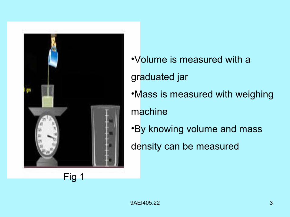
Fig 1
•Volume is measured with a
graduated jar
•Mass is measured with weighing
machine
•By knowing volume and mass
density can be measured
9AEI405.22 4
Necessity of measurement of density
• Density measurement is necessary in chemical
industries where the determination of concentration of a
solution or mixture is based on density.
• In flow measurements while converting the volumetric
flow rate into the mass flow rate, the density of a
substance should be known.
9AEI405.22 5
Types of densitometers
• Densitometer is a device used to measure the density of
a given sample
• There are three types of densitometers
• They are :
• Displacement type densitometers
• Fluid dynamic type densitometers
• Capacitance type densitometers
Displacement Type Densitometer
9AEI405.23 6
9AEI405.23 7
Operation
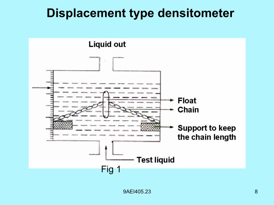
• It mainly consists of float and chain
• The test liquid will flow through the transparent
chamber from bottom to top.
• When the density of the fluid increases a buoyant force
increases in the test liquid.
• The increase in the force would cause the flow to rise.
9AEI405.23 8
Displacement type densitometer
Fig 1
9AEI405.23 9
• As the float rises it will take up a greater portion of
the chain.
• When the density of test liquid decreases the float
comes down.
• A greater portion of the chain weight is taken up by
the supports.
Operation
9AEI405.23 10
• The float moves according to the density of the test
fluid.
• The position of the float can be seen through
transparent chamber in which the measurement is
carried out.
• The new float position is a function of the density.
Operation
Fluid Dynamic type Densitometer
9AEI405.24
9AEI405.24
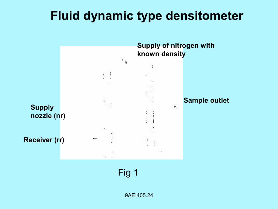
Fluid dynamic type densitometer
Supply of nitrogen with known density
Sample outletSupply nozzle (nr)
Receiver (rr)
Fig 1
9AEI405.24
Operation
• It is used to measure the densities of gases and liquids.
• It mainly consists of two chambers
• Reference chamber
• Measuring chamber
9AEI405.24
Reference chamber:
• The reference chamber consists of
• Supply nozzle (Nr)
• Receiver port (Rr)
• A small outlet port
9AEI405.24
• This chamber is filled with suitable supply of nitrogen at
known density such that the reference pressure (Pr)
serves as a reference value at the receiver port.
9AEI405.24
Measuring Chamber
• The measuring chamber consists of
• Inlet
• Outlet
• Supply Nozzle (Nm)
• Receiver port (Rm)
• This chamber is placed into directly adjacent to
reference chamber
9AEI405.24
• The measuring fluid or gas is pumped through the inlet
and this chamber also receives the nitrogen with known
density
• The differential pressure between the receiving port and
measuring port is a measure of the density of unknown
sample
Capacitance type densitometer
9AEI405.25
9AEI405.25
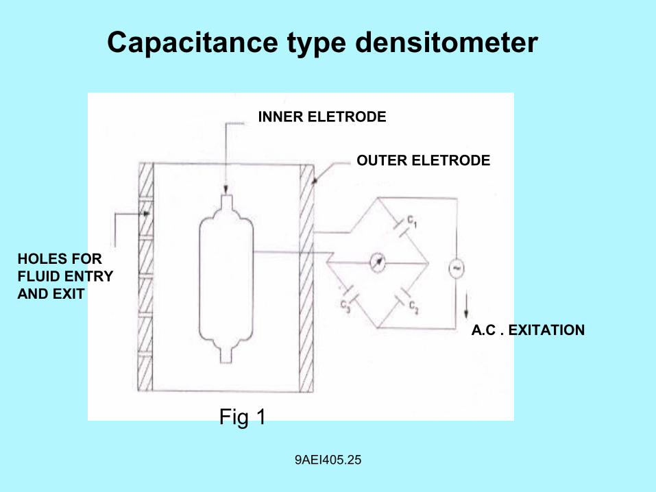
Capacitance type densitometer
INNER ELETRODE
OUTER ELETRODE
A.C . EXITATION
HOLES FOR FLUID ENTRY AND EXIT
Fig 1
9AEI405.25
• It mainly consists of two concentric cylinders
• The sample whose density is to be measured is placed
between these two cylinders
• These cylinders acts as two parallel plates of a capacitor
and the sample acts as the dielectric between the plates
Capacitance type densitometer
9AEI405.25
• The two cylinders are connected to one arm of a bridge
circuit and the outer cylinder consists of holes for fluid
entry and exit
• The bridge circuit measures the capacitance between
the two cylinders
• The capacitance is proportional to dielectric constant
which is in turn is proportional to the density of the fluid
Density and Viscocity Measurement
9AEI405.16
9AEI405.16
Introduction
• It is a measure of the fluidity of the liquid or the gas
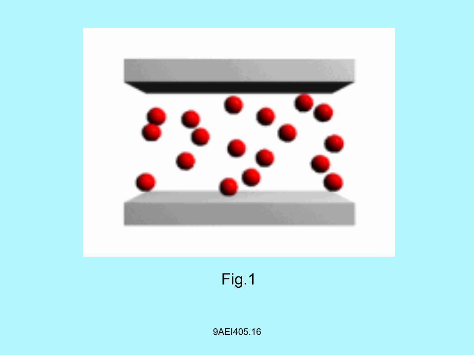
• Many fluids undergo continuous deformation with the
application of shearing stress
• This shear force produces a flow
• If the force-flow relation is linear then the fluid is said to
be Newtonian
9AEI405.16
• For non Newtonian fluids the relation is not only non-
linear but changes from material to material
• When continuous deformation occurs the fluid tries to
oppose this with frictional resistance
• This resistance is measured in terms of consistency
9AEI405.16
Fig.1
9AEI405.16
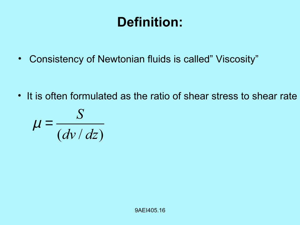
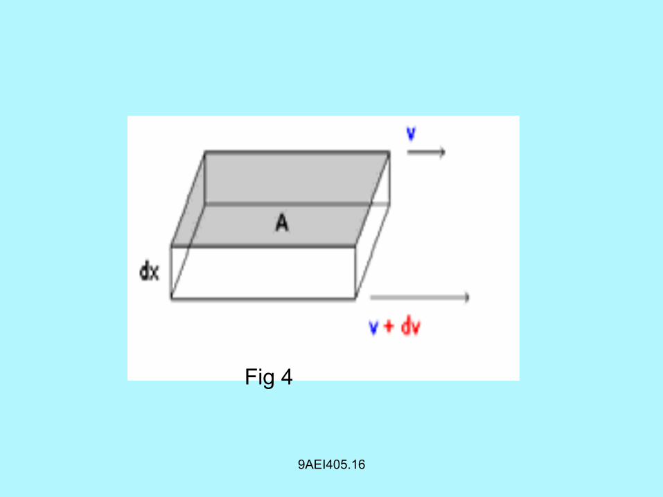
Definition:
• Consistency of Newtonian fluids is called” Viscosity”
( / )
S
dv dzµ =
• It is often formulated as the ratio of shear stress to shear rate
9AEI405.16
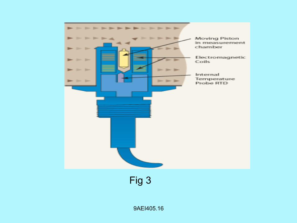
Fig 3
9AEI405.16
Where • S is the shear stress • dv/dz is the velocity gradient
The unit of viscosity is Newton-Sec/m2 = 10 poise
Fluidity is the reciprocal of viscosity units are
rhe = 1/poise
9AEI405.16
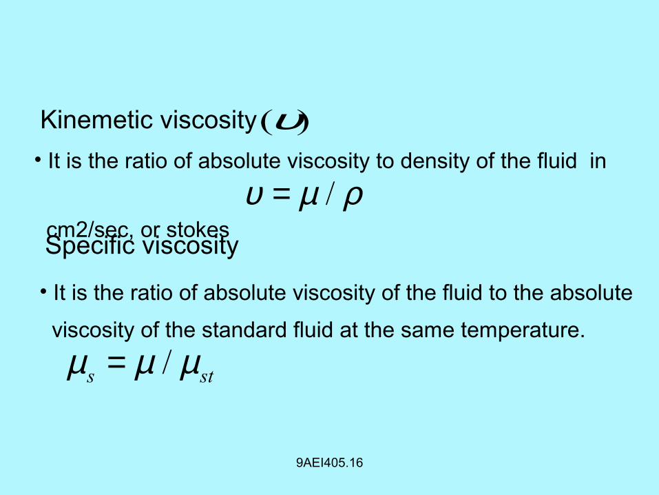
( )υKinemetic viscosity
/υ µ ρ=• It is the ratio of absolute viscosity to density of the fluid in
cm2/sec, or stokesSpecific viscosity
/s stµ µ µ=
• It is the ratio of absolute viscosity of the fluid to the absolute
viscosity of the standard fluid at the same temperature.
9AEI405.16
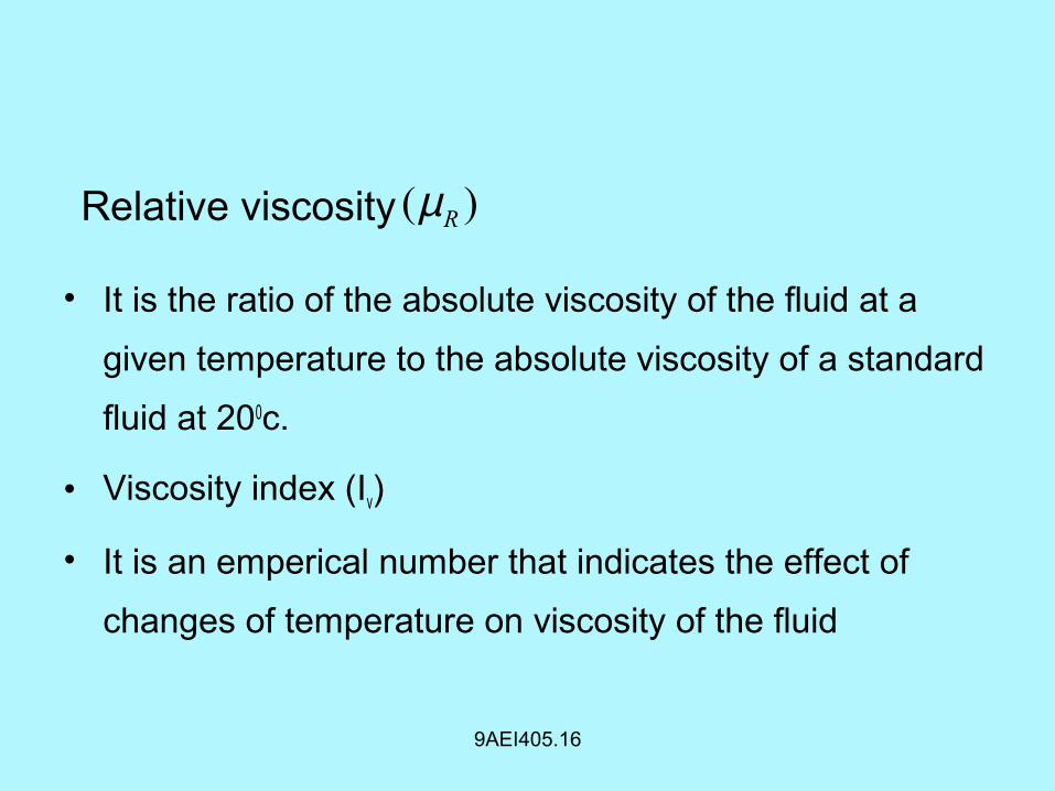
• It is the ratio of the absolute viscosity of the fluid at a
given temperature to the absolute viscosity of a standard
fluid at 200c.
• Viscosity index (Iv)
• It is an emperical number that indicates the effect of
changes of temperature on viscosity of the fluid
( )RµRelative viscosity
9AEI405.16
Fig 4
9AEI405.16
Necessity:
• Measurement of viscosity of lubricating oils, fuels, paints
is taken into consideration before their use
Lubricating oils :-
• Lubricating should be sufficiently viscous so that they are
not squeezed out from the bearings
• Further they should not be too viscous to increase the
resistance to the motion between the moving parts.

9AEI405.16
Paints :-
• In paint spraying the viscosity of paint should be maintained
with certain limits
• Hence the measurement of viscosity is necessary in
process industries
9AEI405.16
Types of viscometer
• There are mainly three types of viscometers used in
measurement viscosity.
• They are:
• Capillary tube viscometer
• Falling ball viscometer
• Rotating concentric cylinder viscometer
Capillary Tube Viscometer
9AEI405.17 TO 18 35
9AEI405.17 TO 18 36
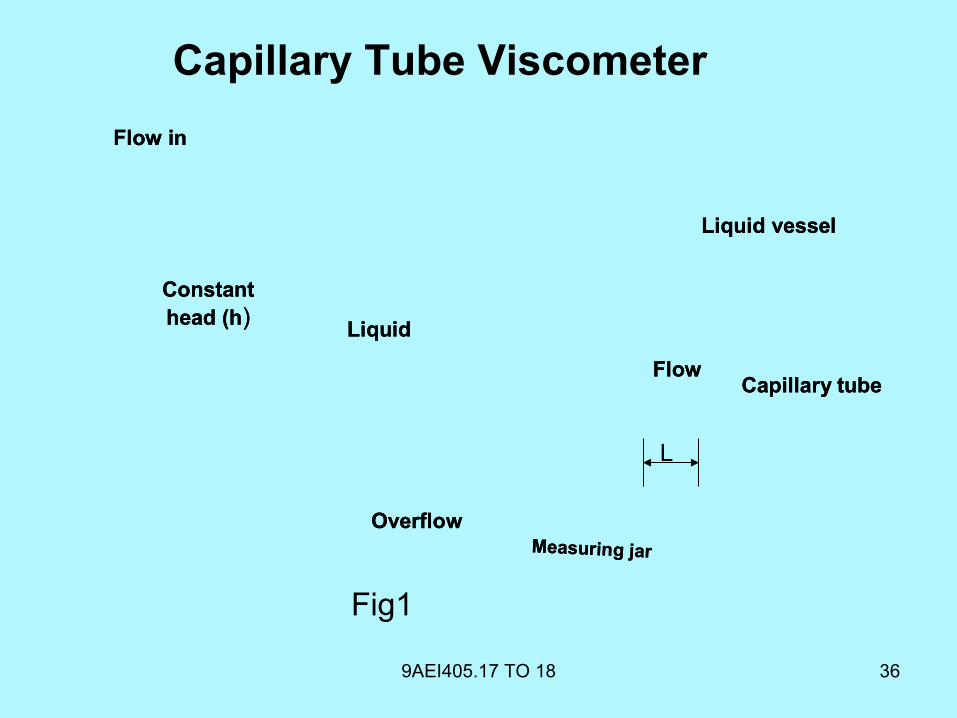
Capillary Tube Viscometer
Flow in
Constant head (h)
Liquid vessel
FlowCapillary tube
Measuring jar
Overflow
Liquid
Flow in
Constant head (h)
Liquid vessel
FlowCapillary tube
Measuring jar
Overflow
Liquid
L
Fig1
9AEI405.17 TO 18 37
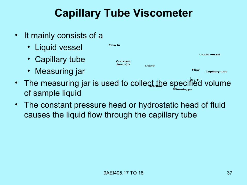
Capillary Tube Viscometer
• It mainly consists of a • Liquid vessel• Capillary tube• Measuring jar
• The measuring jar is used to collect the specified volume of sample liquid
• The constant pressure head or hydrostatic head of fluid causes the liquid flow through the capillary tube
Flow in
Constant head (h)
Liquid vessel
FlowCapillary tube
Measuring jar
Overflow
Liquid
Flow in
Constant head (h)
Liquid vessel
FlowCapillary tube
Measuring jar
Overflow
Liquid
L

9AEI405.17 TO 18 38
• The discharge rate (Q) can be easily calculated by using measuring jar and stop watch
Volume of liquid collected in the measuring jar
Time taken to collect the liquid in the measuring jarQ =
9AEI405.17 TO 18 39
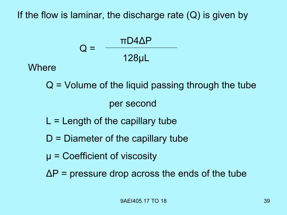
If the flow is laminar, the discharge rate (Q) is given by
Where
Q = Volume of the liquid passing through the tube per second
L = Length of the capillary tube
D = Diameter of the capillary tube
μ = Coefficient of viscosity
ΔP = pressure drop across the ends of the tube
Q =πD4ΔP
128μL
9AEI405.17 TO 18 40
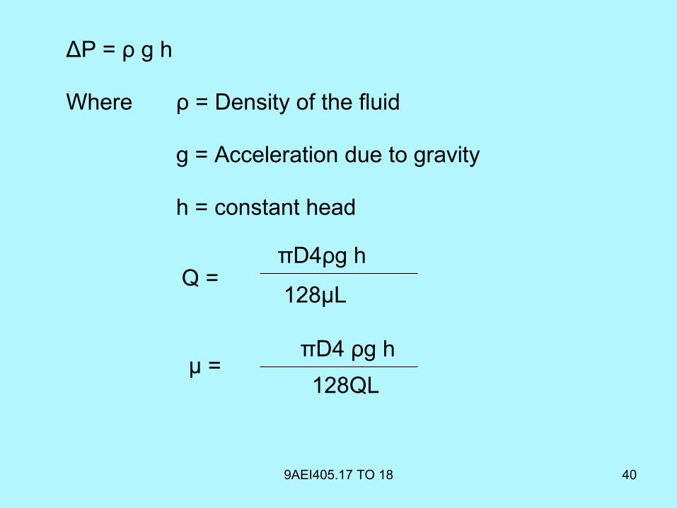
ΔP = ρ g h
Where ρ = Density of the fluid
g = Acceleration due to gravity
h = constant head
Q =πD4ρg h
128μL
μ =πD4 ρg h
128QL
9AEI405.17 TO 18 41
• In the above equation the diameter of Capillary tube is
raised to fourth power
• Hence it is essential to measure it as accurately as
possible
• By using traveling microscope the diameter of the
capillary tube can be measured accurately
• Capillary tube viscometer can be used as a flow
metering device if the viscosity of the liquid is known
9AEI405.17 TO 18 42
Advantages
• Simple in construction
• No maintenance required
• Easy to use
9AEI405.17 TO 18 43
Disadvantage
• The main disadvantage of this viscometer is that it is not
suitable for unclean fluids as the dirt or grit tends to clog
the capillary tube
9AEI405.17 TO 18 44
Applications
• They can be used as secondary standards for the
calibration of other type of viscometers
• They are used in the refineries to measure the viscosity
of petroleum products

Falling Ball Viscometer
9AEI405.19 TO 20 45
9AEI405.19 TO 20 46
Falling ball Viscometer
• Falling ball Viscometer is a device used to calculate the
coefficient of viscosity (µ) of a given sample
9AEI405.19 TO 20 47
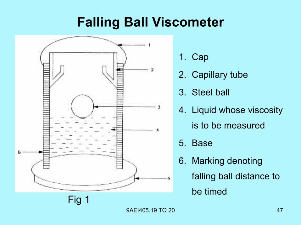
1. Cap
2. Capillary tube
3. Steel ball
4. Liquid whose viscosity
is to be measured
5. Base
6. Marking denoting
falling ball distance to
be timed
Falling Ball Viscometer
Fig 1
9AEI405.19 TO 20 48
Falling ball viscometer-Principle of operation
• It consists of essentially a precision glass tube of 200
mm length
• A perfectly smooth steel ball freely released from the
rest into the test liquid under gravitational force
• The ball obtains a maximum terminal velocity, when
upward and downward forces acting on it which are
equal
9AEI405.19 TO 20 49
• The following forces act on the ball
• Weight of ball (w)
• Upward force (fl)
• Viscous force (F)
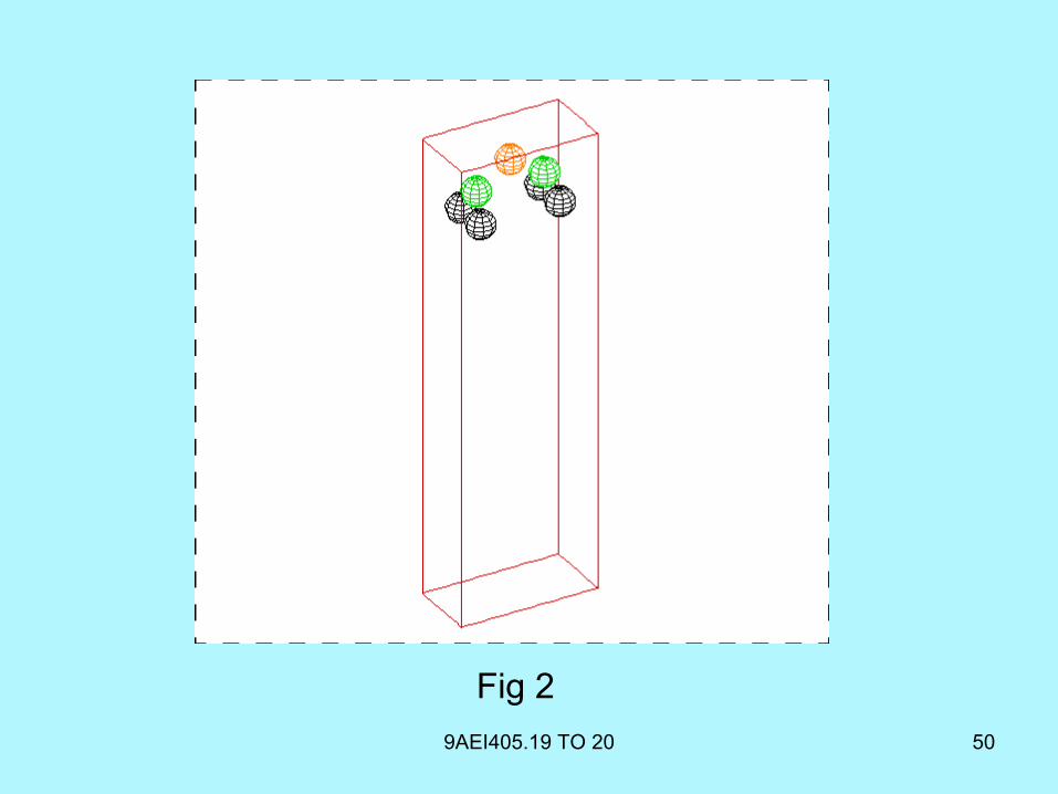
9AEI405.19 TO 20 50
Fig 2
9AEI405.19 TO 20 51
• Weight of the ball that acts vertically downward
i.e. w = 4/3 π r3 ρb g
• Where r = Radius of ball
ρb = Density of ball
g = Acceleration due to gravity
9AEI405.19 TO 20 52
Upward force (fl) of the fluid due to buoyancy
i.e. Fl = 4/3 π r3ρlg
Where ρl = Density of the liquid whose
viscosity is to be measured
9AEI405.19 TO 20 53
Viscous force (F) in upward direction
i.e. F = 6πμr v
Where μ = Coefficient of viscosity
V = Constant velocity with which
the ball moves through the liquid
9AEI405.19 TO 20 54
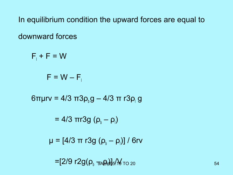
In equilibrium condition the upward forces are equal to
downward forces
Fl + F = W
F = W – Fl
6πμrv = 4/3 π3ρb g – 4/3 π r3ρl g
= 4/3 πr3g (ρb – ρl)
μ = [4/3 π r3g (ρb – ρl)] / 6rv
=[2/9 r2g(ρb – ρl)] /V
9AEI405.19 TO 20 55
• The terminal velocity (V) can be calculated by measuring
the timing of the fall of the ball and the distance between
the markings on the glass tube
• V= Distance / Time
• By measuring the density of ball (ρb), density of liquid (ρl),
radius of the ball (r) and knowing terminal velocity (V) the
coefficient of viscosity (µ) can be calculated
Rotating Viscometer
9AEI405.21 56
9AEI405.21 57
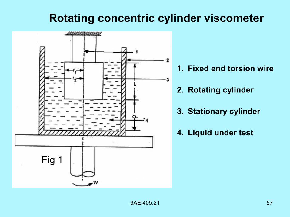
Rotating concentric cylinder viscometer
1. Fixed end torsion wire
2. Rotating cylinder
3. Stationary cylinder
4. Liquid under test
Fig 1
9AEI405.21 58
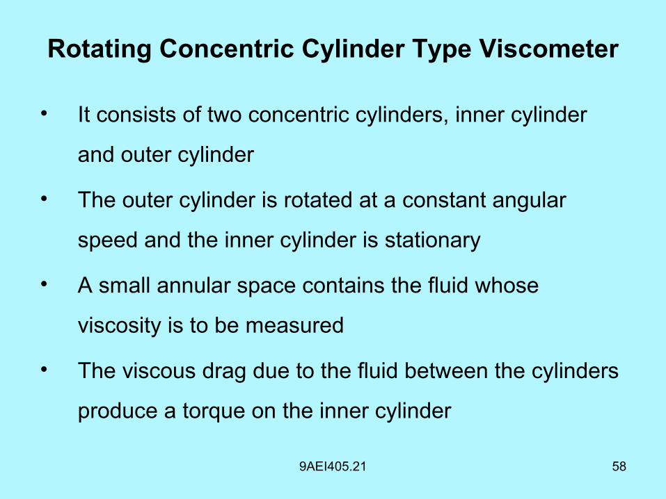
• It consists of two concentric cylinders, inner cylinder
and outer cylinder
• The outer cylinder is rotated at a constant angular
speed and the inner cylinder is stationary
• A small annular space contains the fluid whose
viscosity is to be measured
• The viscous drag due to the fluid between the cylinders
produce a torque on the inner cylinder
Rotating Concentric Cylinder Type Viscometer
9AEI405.21 59
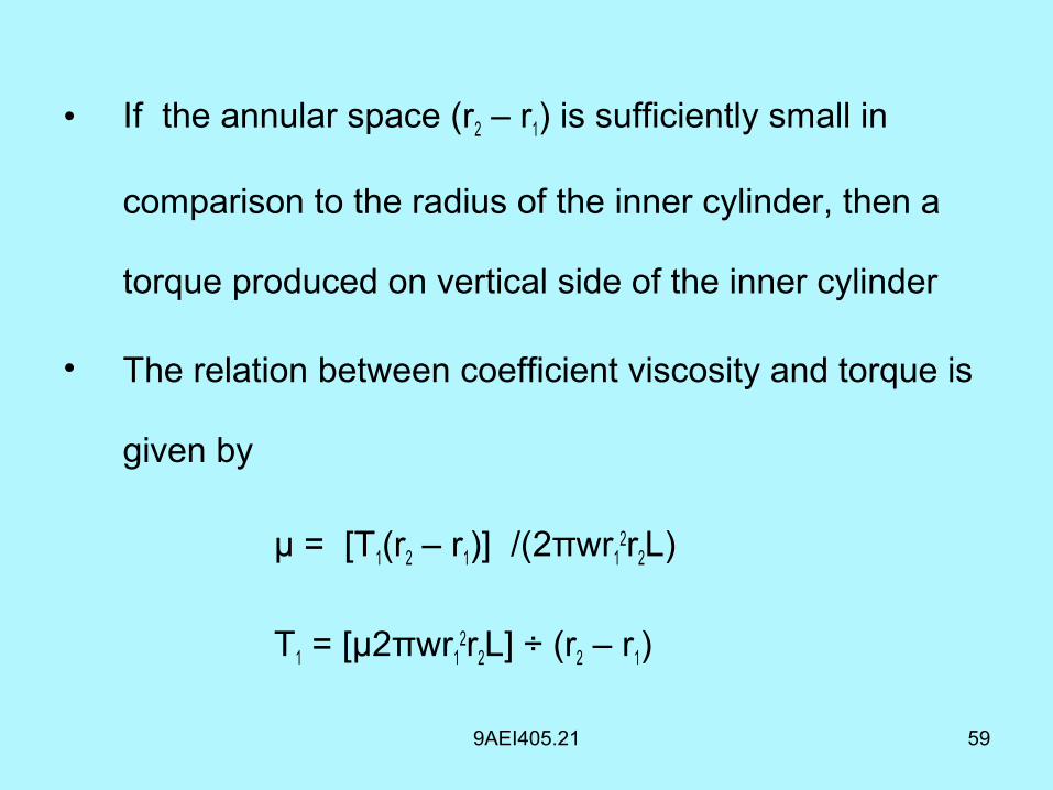
• If the annular space (r2 – r1) is sufficiently small in
comparison to the radius of the inner cylinder, then a
torque produced on vertical side of the inner cylinder
• The relation between coefficient viscosity and torque is
given by
μ = [T1(r2 – r1)] /(2πwr12r2L)
T1 = [µ2πwr12r2L] ÷ (r2 – r1)
9AEI405.21 60
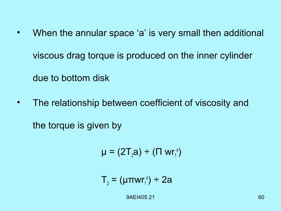
• When the annular space ‘a’ is very small then additional
viscous drag torque is produced on the inner cylinder
due to bottom disk
• The relationship between coefficient of viscosity and
the torque is given by
µ = (2T2a) ÷ (Π wr14)
T2 = (μπwr14) ÷ 2a
9AEI405.21 61
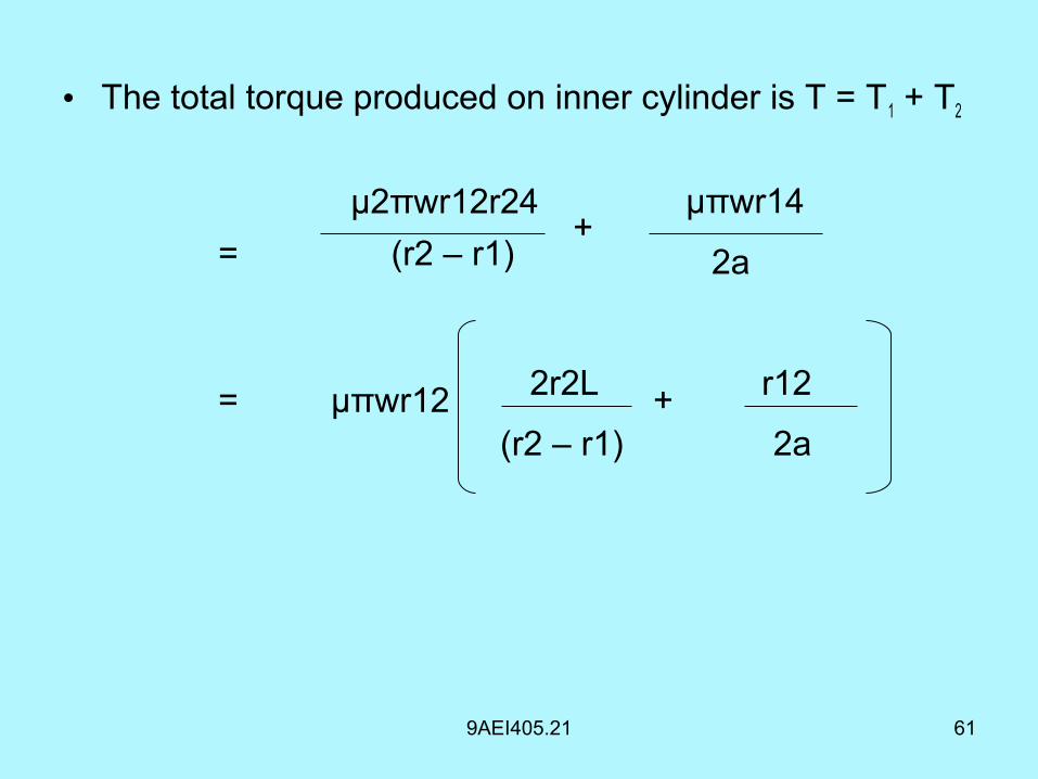
• The total torque produced on inner cylinder is T = T1 + T2
μ2πwr12r24+
μπwr14
= (r2 – r1) 2a
= μπwr12 2r2L + r12
(r2 – r1) 2a
9AEI405.21 62
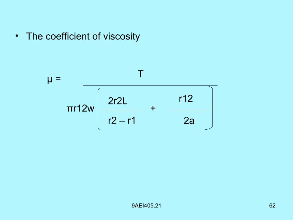
• The coefficient of viscosity
πr12w2r2L
r2 – r1+
r12
2a
Tμ =