11-(n+1)
13
IncidentSite
11-1
11-n611-26
(12) United States PatentJorgensen et al.
(54) COMMUNICATION PATH FOR EXTREMEENVIRONMENTS
(75) Inventors: Charles C. Jorgensen, Palo Alto, CA(US); Bradley J. Betts, Burlingame, CA(US)
(73) Assignee: The United States of America asrepresented by the United StatesNational Aeronautics and SpaceAdministration, Washington, DC (US)
(*) Notice: Subject to any disclaimer, the term of thispatent is extended or adjusted under 35U.S.C. 154(b) by 1141 days.
(21) Appl. No.: 11/111,620
(22) Filed: Apr. 20, 2005
(51) Int. Cl.G08B 1108 (2006.01)
(52) U.S. Cl . ............................... 340/539.11; 340/572.1(58) Field of Classification Search ............ 340/539.11,
340/572.1, 686.1, 825.49, 10.1, 573.1, 586.1See application file for complete search history.
(lo) Patent No.: US 7,796,026 B1(45) Date of Patent: Sep. 14, 2010
(56) References Cited
U.S. PATENT DOCUMENTS5,689,238 A * 11/1997 Cannon et al. ........... 340/572.1
2001/0036832 Al * 11/2001 McKay ....................... 455/4562005/0231359 Al * 10/2005 Kampel et al. ......... 340/539.132005/0237193 Al * 10/2005 Namm et al . ............ 340/572.1
* cited by examiner
Primary Examiner Phung Nguyen(74) Attorney, Agent, or Firm John Schippar; RobertPadilla; Diana Cox
(57) ABSTRACT
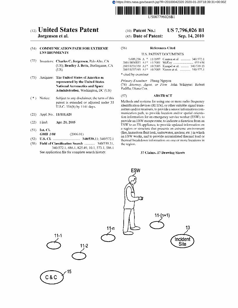
Methods and systems for using one or more radio frequencyidentification devices (RFIDs), or other suitable signal trans-mitters and/or receivers, to provide a sensor information com-munication path, to provide location and/or spatial orienta-tion information for an emergency service worker (ESW), toprovide an ESW escape route, to indicate a direction from anESW to an ES appliance, to provide updated information ona region or structure that presents an extreme environment(fire, hazardous fluid leak, underwater, nuclear, etc.) in whichan ESW works, and to provide accumulated thermal load orthermal breakdown information on one or more locations inthe region.
37 Claims, 17 Drawing Sheets
15C&C
https://ntrs.nasa.gov/search.jsp?R=20100042320 2020-01-20T18:39:31+00:00Z
Ca, NcOU
m N coU_ —
z caE o
YW Oco N.^az°O
y FN
rnN`N
Z
U.S. Patent Sep. 14, 2010 Sheet 1 of 17 US 7,796,026 B1
w
M=rnNU L67 J co
Q
00
WJ LuW LL
U CDz tiO
U Cfl
co
w
EW CDaa c°9
cnW ^Hz
U N
O U- U MN ^ O
F
N M
a(a u')N
M C`-CD
2rloco
^IW C-V
WU ^
c O ti C^
wI
a CON w IL
0Ofr d
ll')
Uco
U
N
1
Fig. 3
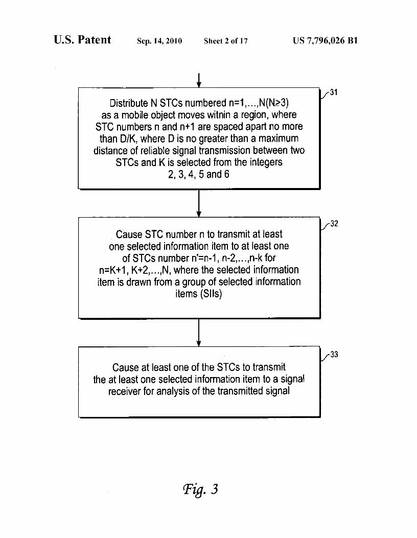
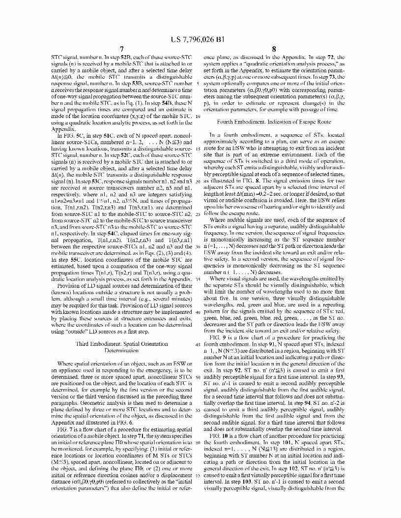
Distribute N STCs numbered n=1 I ... ,N(NL>3)as a mobile object moves witnin a region, where
STC numbers n and n+1 are spaced apart no morethan DIK, where D is no greater than a maximum
distance of reliable signal transmission between twoSTCs and K is selected from the integers
2, 3, 4, 5 and 6
Cause STC number n to transmit at leastone selected information item to at least one
of STCs number n'=n-1, n-2,...,n-k forn=K+1, K+2,...,N, where the selected informationitem is drawn from a group of selected information
items (Slls)
if
Cause at least one of the STCs to transmitthe at least one selected information item to a signal
receiver for analysis of the transmitted signal
f31
f32
f33
U.S. Patent Sep. 14, 2010 Sheet 2 of 17 US 7,796,026 B1
MobileST
Source-n=n3 STC
Ti .4C
U.S. Patent Sep. 14, 2010 Sheet 3 of 17
US 7,796,026 B1
SRn=1
MobileST
ESW
n=N SR 'Fig.4^
&SR
Source-n=n l STC
Source-n=n 2 STC
(-I
Esw
Fig. 6
U.S. Patent Sep. 14, 2010 Sheet 4 of 17 US 7,796,026 B1
n=1Source-STC
cz
&Source-STC
MobileST
ESW
Fig. 4B
&Source-STC
^J^
U.S. Patent Sep. 14, 2010 Sheet 5 of 17 US 7,796,026 B1
Cause ST, carried by or attached to a mobile object, totransmit a LD signal at a selected time
Receive the transmitted ST signal atspaced apart, noncollinear SRs (N>3), with knownlocations, and measure time at which each of the
transmitted signals is received
Receive the measured time for each of the SRsand estimate location coordinates for the RFIDbased upon comparison of the measured times,
using a quadratic location analysis process
/-51A
52A
53A
Fig. SA
U.S. Patent Sep. 14, 2010 Sheet 6 of 17 US 7,796,026 B1
Each of N spaced apart, noncollinear source-STCs,numbered n = 1,..., N (N>_3) and having known
locations, transmits a distinguishablesource-STC signal number S1(n)
Each of the N source-STC signals (n) is receivedby a mobile STC, carried by or attached to a mobile
object; after a selected time delay at ot(n), the mobileSTC transmits a distinguishable response signal S2(n)
Source-STC number n receives the response signalnumber n and determines an elapsed time for oneway signal propagation between the source-STC
number n and the mobile STC
The N signal propagation times are compared andan estimate is made of the location coordinates(X, Y, Z) of the mobile STC, using a quadratic
location analysis process
f51B
,/-52B
f53B
f54B
Fig. SB
U.S. Patent Sep. 14, 2010 Sheet 7 of 17 US 7,796,026 B1
Each of N spaced apart, noncollinear source-STCs,numbered n =1,..., N (N>_3) and having known
locations, transmits a distinguishablesource-STC signal number S1(n)
51
Each of the N source-STC signals (n) is receivedby a mobile STC, carried by or attached to a mobile
object; after a selected time delay at At(n), the mobileSTC transmits a distinguishable response signal S2(n)
Source-STC no. n 2 receives the response signalS2(n 1 ), source-STC no. n 3 receives the response
signal S2(n 2), and source-STC no. n 1 receivesthe response signal S2(n 3 ), where n 1 = n 2 =n 3= n1
and 1 <_ n 1 , n 2 , n 3 , z N;
7TDetermine signal propagation times T(n 1 , r, n2),T(n 2 , r, n 3 ), and T(n 3 , r, n 1 ); determine one-way
signal propagation times T(n 1 , r), T(n 2 , r),and T(n 3 , r)
Estimate location coordinates of mobile STCfrom comparison of the signal propagationtimes T(n 1 , r), T(n 2 , r), and T( 3 , r), using a
quadratic location analysis process
53C
54C
55C
Fig. 5C
U.S. Patent Sep. 14, 2010 Sheet 8 of 17 US 7,796,026 B1
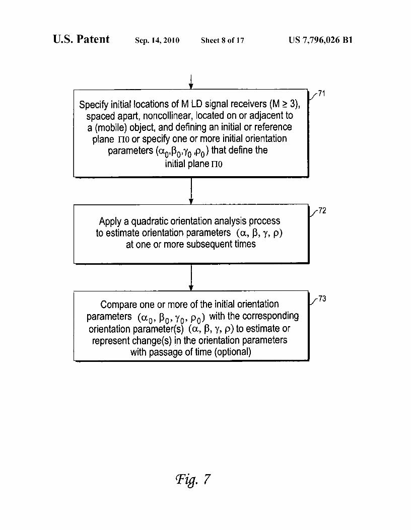
Specify initial locations of M LD signal receivers (M> 3),spaced apart, noncollinear, located on or adjacent toa (mobile) object, and defining an initial or reference
plane no or specify one or more initial orientationparameters ((xo'Ro ,yo po) that define the
initial plane noMMMMMMMi
Ir
Apply a quadratic orientation analysis processto estimate orientation parameters (a, (3, y, p)
at one or more subsequent times
Compare one or more of the initial orientationparameters (a o , Ro , y o , po) with the correspondingorientation parameter(s) ((x, R, y, p) to estimate orrepresent change(s) in the orientation parameters
with passage of time (optional)
f71
f72
f73
Fig. 7
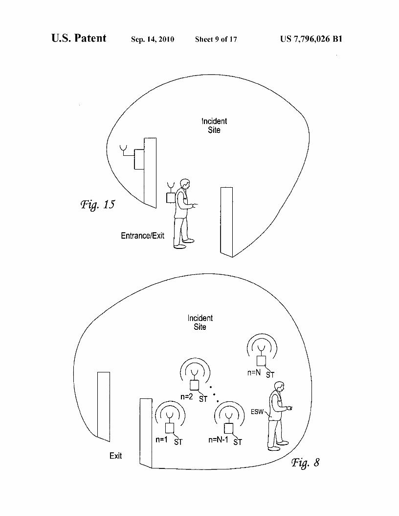
Fig.
U.S. Patent Sep. 14, 2010 Sheet 9 of 17 US 7,796,026 B1
IncidentSite
n
n n=N S
n=2 ST
nn ESW
n=1 S n=N-1 ST
ExitFig. 8
Tig. 9
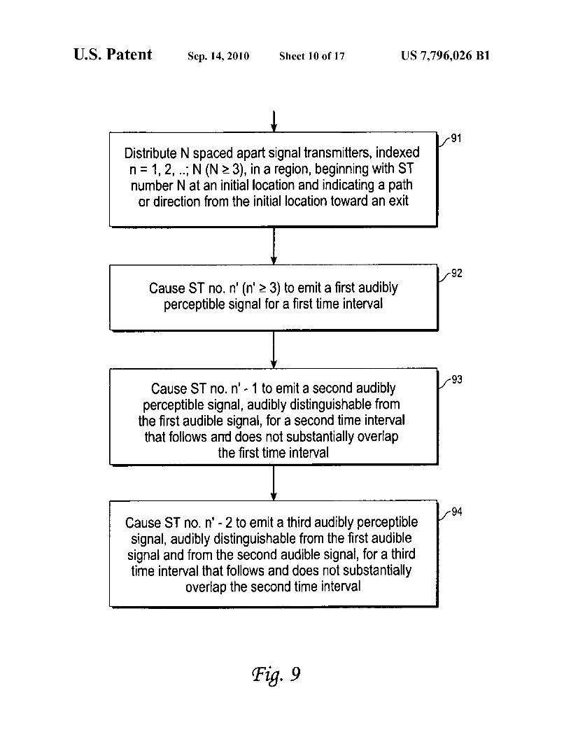
Distribute N spaced apart signal transmitters, indexedn = 1, 2, ..; N (N >_ 3), in a region, beginning with STnumber N at an initial location and indicating a path
or direction from the initial location toward an exit
Cause ST no. n' (n' >_ 3) to emit a first audiblyperceptible signal for a first time interval
Cause ST no. n'- 1 to emit a second audiblyperceptible signal, audibly distinguishable from
the first audible signal, for a second time intervalthat follows and does not substantially overlap
the first time interval
if
Cause ST no. n'- 2 to emit a third audibly perceptiblesignal, audibly distinguishable from the first audible
signal and from the second audible signal, for a thirdtime interval that follows and does not substantially
overlap the second time interval
1-91
1-92
1-93
1-94
U.S. Patent Sep. 14, 2010 Sheet 10 of 17 US 7,796,026 B1
U.S. Patent Sep. 14, 2010 Sheet 11 of 17 US 7,796,026 B1
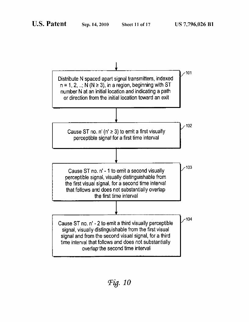
Distribute N spaced apart signal transmitters, indexedn =1, 2, ..; N (N > 3), in a region, beginning with STnumber N at an initial location and indicating a path
or direction from the initial location toward an exit
Cause ST no. n' (n' > 3) to emit a first visuallyperceptible signal for a first time interval
Cause ST no. n'- 1 to emit a second visuallyperceptible signal, visually distinguishable fromthe first visual signal, for a second time intervalthat follows and does not substantially overlap
the first time interval
Cause ST no. n'- 2 to emit a third visually perceptiblesignal, visually distinguishable from the first visualsignal and from the second visual signal, for a thirdtime interval that follows and does not substantially
overlap-the second time interval
101
1102
103
j- 104
Fig. 10
3R
AA
SR
U.S. Patent Sep. 14, 2010 Sheet 12 of 17 US 7,796,026 B1
QT
Eig. 13
Tig. 12
U.S. Patent Sep. 14, 2010 Sheet 13 of 17 US 7,796,026 B1
141
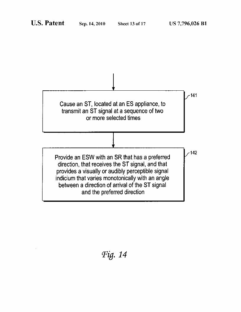
Cause an ST, located at-an ES appliance, totransmit an ST signal at a sequence of two
or more selected times
142Provide an ESW with an SR that has a preferreddirection, that receives the ST signal, and thatprovides a visually or audibly perceptible signalindicium that varies monotonically with an angle
between a direction of arrival of the ST signaland the preferred direction
Fig. 14
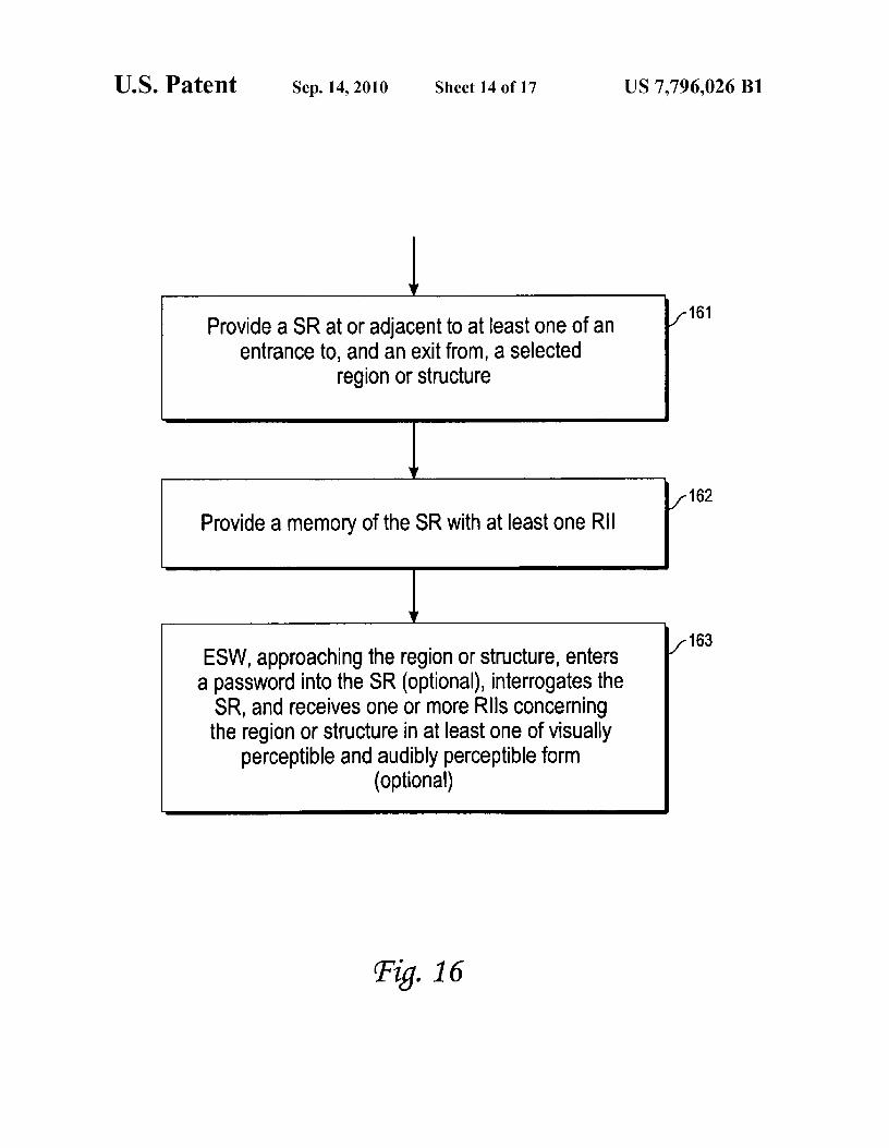
Fig. 16
Provide a SR at or adjacent to at least one of anentrance to, and an exit from, a selected
region or structure
Provide a memory of the SR with at least one RII
ESW, approaching the region or structure, entersa password into the SR (optional), interrogates the
SR, and receives one or more Rlls concerningthe region or structure in at least one of visually
perceptible and audibly perceptible form(optional)
161
^ 162
163
U.S. Patent Sep. 14, 2010 Sheet 14 of 17 US 7,796,026 B1
U.S. Patent Sep. 14, 2010 Sheet 15 of 17
US 7,796,026 B1
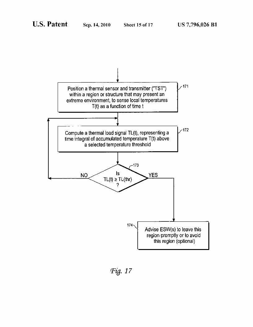
Position a thermal sensor and transmitter ("TST") 171
within a region or structure that may present anextreme environment, to sense local temperatures
T(t) as a function of time t
Compute a thermal load signal TL(t), representing a 172
time integral of accumulated temperature T(t) abovea selected temperature threshold
173
IsNOTL(t) >_ TL(thr)
YES
174Advise ESW(s) to leave thisregion promptly or to avoid
this region (optional)
Fig. 17
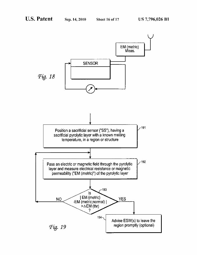
Fig. 18
U.S. Patent Sep. 14, 2010 Sheet 16 of 17 US 7,796,026 B1
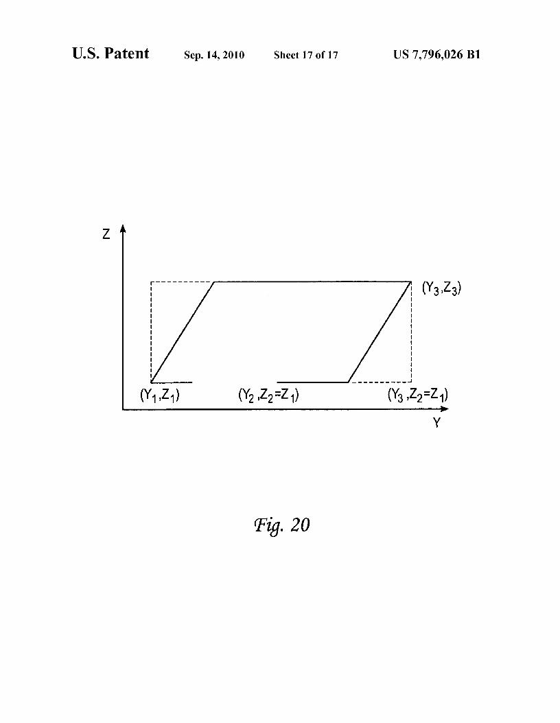
Position a sacrificial sensor ("SS"), having a 191
sacrificial pyrolytic layer with a known meltingtemperature, in a region or structure
Pass an electric or magnetic field through the pyrolytic 192
layer and measure electrical resistance or magneticpermeability ("EM (metric)") of the pyrolytic layer
193
N<-EM
IsM (metric)etric;normal)EM (thr)
194Advise ESW(s) to leave the
Fig. 19 region promptly (optional)
YES
Z
^3)
Y
Fig. 20
U.S. Patent Sep. 14, 2010 Sheet 17 of 17 US 7,796,026 B1
US 7,796,026 B11
2COMMUNICATION PATH FOR EXTREME
tively low oxygen content, high auditory intensity, high elec-
ENVIRONMENTS
tromagnetic intensity, high visible or near-visible lighting,low or non-existent visible lighting, high nuclear flux.
ORIGIN OF THE INVENTION
In a first embodiment, as the active group moves toward5 and/or works within the extreme environment, the active
This invention was made, in part, by one or more employ- group distributes a sequence of spaced apart RFID devices orees of the U.S. government. The U.S. government has the other devices providing similar features that communicateright to make, use and/or sell the invention described herein with each other, preferably but not necessarily in a selectedwithout payment of compensation therefor, including but not order of communication. A first RFID signal format provideslimited to payment of royalties. io a preamble including sensor data for many kinds of sensors
and identifying the source RFID for this information. In sec-FIELD OF THE INVENTION ond and third embodiments, one or a small group of RFIDs or
other STs or STCs provides location and spatial orientationThis invention relates to reliable communication of infor- for an emergency services worker (ESW). In a fourth embodi-
mation in an extreme environment, including an emergency 15 ment, a sequence of RFIDs serves as an escape route for ansite. ESW, by providing an audibly or visually perceptible
sequence of signals that indicate a path toward an exit. In aBACKGROUND OF THE INVENTION
fifth embodiment, an RFID with angle-dependent output sig-nal indicates a location of an emergency service (ES) appli-
Firefighters and other emergency service workers who 2o ance, such as a fire hose. In a sixth embodiment, an interro-actively work in extreme environments (e.g., in the presence gatable RFID or similar receiver appliance providesof low visibility, high temperature, high pressure, high toxic- information locally concerning conditions at a site and/ority, high auditory intensity or low oxygen content) often uti- results of the most recent inspection of the site. In seventh andlize a "buddy touch" system; wherein a lead worker sets a path eighth embodiments, a thermal sensing RFID or similar ther-on hands and knees, and each succeeding worker maintains 25 mal sensing device indicates the present thermal condition oftouch contact with the preceding worker's legs or other the site, relative to a critical site condition that is associatedextremities, while sweeping his/her own limbs to locate vic- with extreme danger.tims and/or obstacles. During this procedure, which is both
An RFID is a small radio transmitter, receiver and sensor
slow and dangerous, a fire hose and/or emergency service that can be used, for example, for inventories and to facilitatedelivery line and/or communications line may be pulled along 30 labeling in a commercial activity. An RFID can be queried,as well to serve immediate emergency needs and to serve as within its transmission range (23 feet in one version), by aan escape path. Given the possibility for encountering local
hand held device to reveal stored information. Each RFID can
extreme environments (heat pockets, high toxic chemical
have a size as small as a U.S. nickel, but is preferably some-content, collapsed areas, etc.) and/or the possibility of escape what larger if a plurality of RFIDs is to be distributed in apath blockages, a safe, reliable and low cost alternative is 35 sequence according to a plan. In some embodiments dis-clearly needed that also provides information to command closed here, an RFID is programmed to automatically trans-and control personnel concerning (1) the present condition of mit selected information at a sequence of specified times, orthe active workers, (2) the present conditions in and around upon demand.the incident site, and (3) the present conditions adjacent to a One version of an RFID operates at about 433 MHz, butchosen escape path. 40 this frequency can be varied somewhat to provide distinguish-
What is needed is a communication system that facilitates able frequencies among a sequence of RFIDs. Presently, tworeliable communication of information, including location
RFIDs can reliably communicate with each other over a range
and present condition of the active worker(s), local tempera- of up to about 7 meters (approximately 23 feet) in almost anyture and other relevant local environmental variable values reasonable environment, in temperatures ranging from —40 °and relevant changes in these values between one or more 45 F. to 185 ° F., at a rate of 1.8-2.2 pulses/sec. Additionalpersons within an extreme environment and one or more communication range, up to 50-300 feet, can be obtained bysub-systems located outside this extreme environment. Pref- supplementing the RFIDs with an external package. Two orerably, the system should be flexible so that the variables more RFID devices use RS232 or RS485 or Ethernet TCP/IPwhose values are communicated can be changedby one of the communication protocol to communicate with each other,communicators and should permit both automatic reporting 50 serial format, in simplex or half duplex modes. A signaland volitional reporting. transmitted or received by an RFID may be expressed in
256-2048 bits. A given RFID may be read/write (RW) orSUMMARY OF THE INVENTION may be read only (RO), may have a diameter of between
0.625 and 3.75 inches, and maybe used with an antenna cableThese needs are met by the invention, which provides a 55 of any reasonable length. Up to four antennas can be linked to
sequence of path communicators, based on devices such as a single RFID device, as presently available. Optionally, anradio frequency identifier devices ("RFIDs"), or other suit- RFID system of devices, available from RFID, Inc. inAurora,able signal transmitters ("STs") and/or signal receivers
Colo. and from other suppliers, includes a handheld reader or
("SRs") and/or signal transceivers ("STCs"), that communi- reader-programmer, operating at 2.45 GHz, with up to 24cate with each other and define one or more communication 60 Mbytes of memory. RFIDs are one of several short rangepaths, including redundant paths if desired, between a group wireless communication systems that can be used here.of one or more persons (the "active group") working in anextreme environment and one or more sub-systems located in
BRIEF DESCRIPTION OF THE DRAWINGSa non-extreme environment. As referred to herein, an"extreme environment" includes the presence of at least one 65 FIG. 1 schematically illustrates distribution of a sequenceof, but is not limited to, high pressure, high temperature, of RFID devices by an ESW in or near an extreme environ-relatively high concentration of a toxic or noxious gas, rela- ment.
US 7,796,026 B13
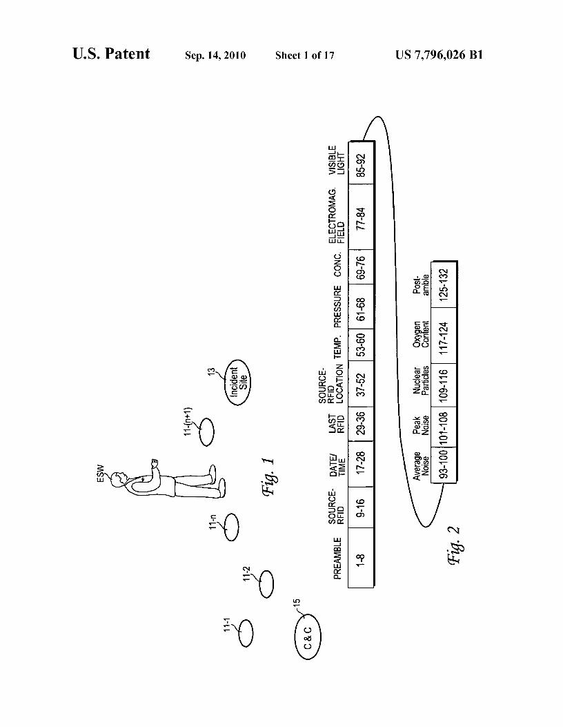
4FIG. 2 illustrates a suitable RFID signal format. successfully passed up the line and/or down the line becauseFIG. 3 is a flow chart of a procedure for the embodiment in of inoperability of another STC in the sequence. Where Kth
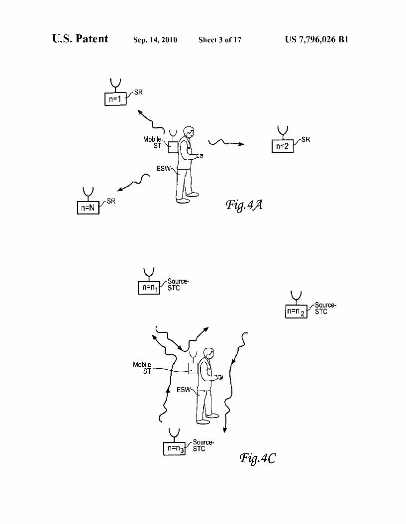
FIG. 1. order redundancy is built in, it is preferable that the nearestFIGS. 4A, 4B and 4C illustrated three versions of determi- neighbor distance between adjacent STCs be no greater than
nation of signal propagation time for a second embodiment to 5 D/K, where D is a maximum communication range betweenestimate location of an object. two STC devices.
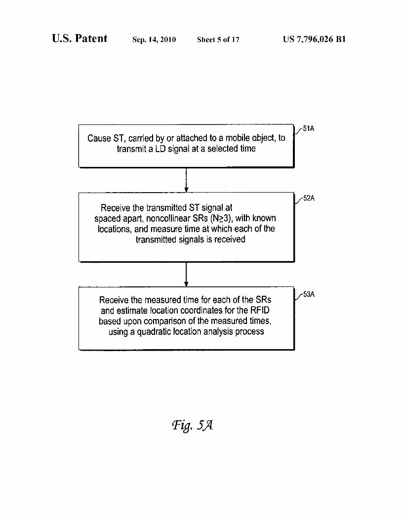
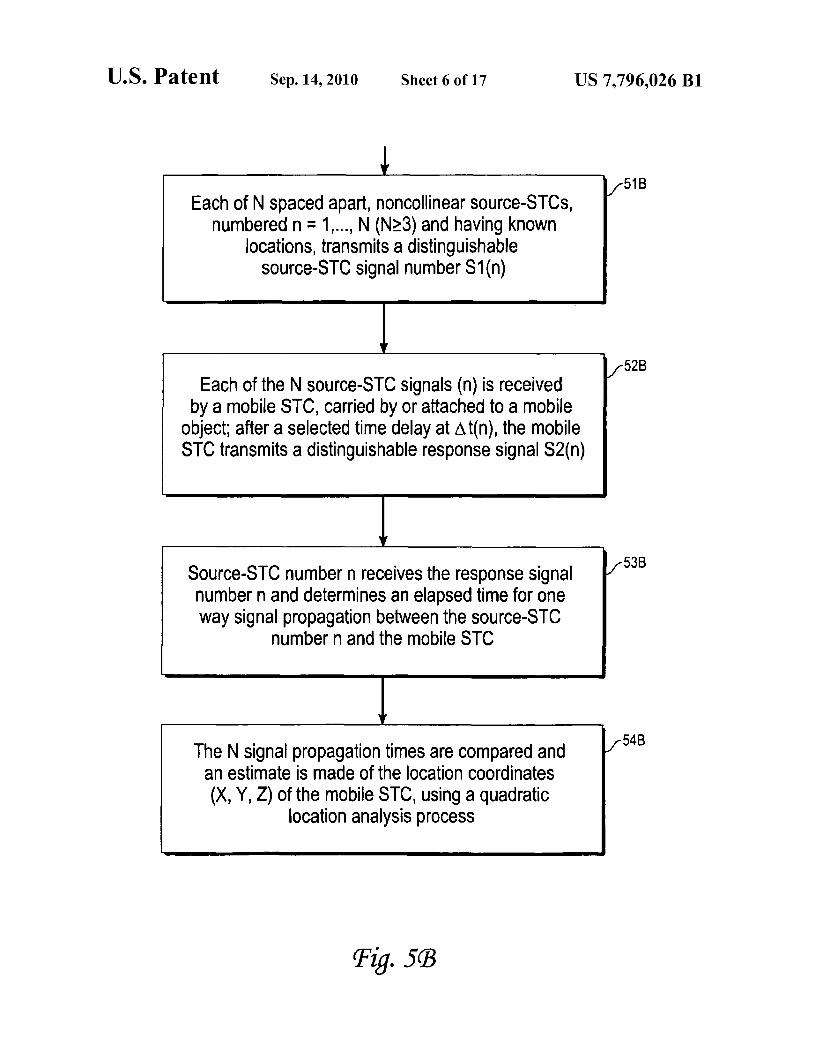
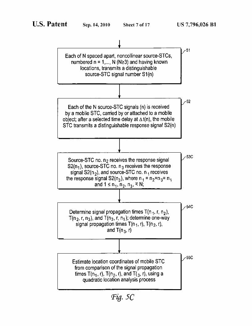
FIGS. 5A, 5B and 5C are flow charts, corresponding to the
One or more STCs in the sequence may include a thermalversions of signal propagation time illustrated in FIGS. 4A, sensor, a barometric sensor, one or more chemical sensors, an4B and 4C, for estimation of location coordinates of an object. electromagnetic sensor, a noise sensor and/or one or more
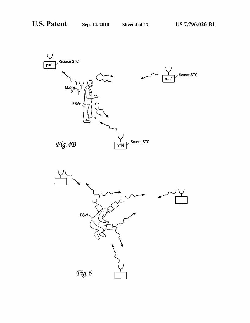
FIG. 6 illustrates estimation of spatial orientation of an io nuclear particle sensors associated therewith in order to pro-object. vide selected information on the environment at and adjacent
FIG. 7 is a flow chart of a procedure for estimation of
to the incident site. A signal transmitted by a STC may thusspatial orientation of an object. include one or more of the following sensor information items
FIG. 8 illustrates use of a sequence of RFIDs to indicate a
(collectively referred to as "SII items"): time of transmission;path toward an exit. 15 STC no. for the source of the information; location and/or
FIGS. 9 and 10 are flow charts of procedures for indicating orientation of the transmitting STC (not necessarily thea path toward an exit, as illustrated in FIG. 8. source); temperature at the transmitting STC location; pres-
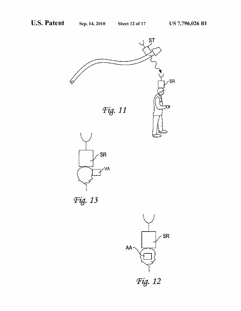
FIGS. 11, 12 and 13 illustrates use of an angular orientation sure at the transmitting STC location; concentration of speci-RFID to indicate a direction to a firefighting appliance, such
fied chemical or compound at the transmitting STC location;
as a fire hose. 20 electromagnetic field intensity at the transmitting STC loca-FIG. 14 is a flow chart of a procedure forpracticing the fifth
tion; visible light index at the transmitting STC location;
embodiment. average noise intensity at the transmitting STC location; peakFIG. 15 illustrates use of an interrogatable RFID, posi- noise intensity at the transmitting STC location; flux of
tioned near an entrance to an incident site, to provide present nuclear particles (alpha, beta, gamma and/or ion) at the trans-information about the site. 25 miffing STC location; and estimated oxygen content at the
FIG. 16 is a flow chart of a procedure for practicing the transmitting STC location. The STC signal is passed to,sixth embodiment. received by and analyzed by a command and control
FIGS. 17 and 19 are flow charts of procedures for practic- ("C&C") sub-system that is located near the incident site. Theing the seventh and eighth embodiments
C&C sub-system preferably monitors the time of transmis-
FIGS. 18 illustrates use of a thermal sensor RFID to pro- 30 sion associated with the received sensor signal and monitorsvide a measure of high temperature exposure at an incident any significant change with time of the sensor signal, in ordersite. to identify an approach to a critical value at or near a location
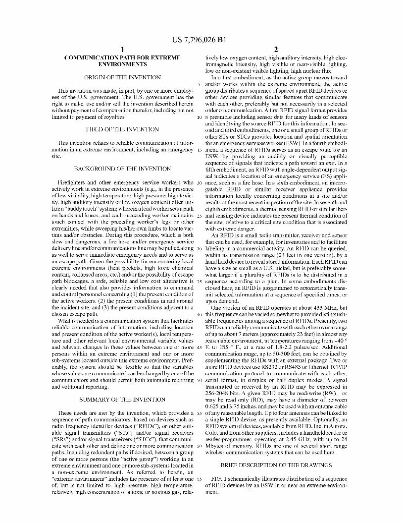
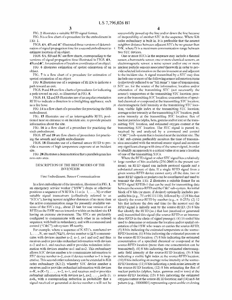
FIG. 20 illustrates a demonstration that a parallelogram has of one of the transmitting STCs.non-zero area.
Where the RFID signal or other STC signal has a relatively35 large number of bits available (256-2048 in the present ver-
DESCRIPTION OF THE BEST MODES OF THE sions), an RFID signal can include protocol signals and aINVENTION substantial amount of data. If a single RFID signal from a
given source-RFID device cannot carry all the data, two orFirst Embodiment. Sensor Communications more RFID signals or packets can be coordinated and used to
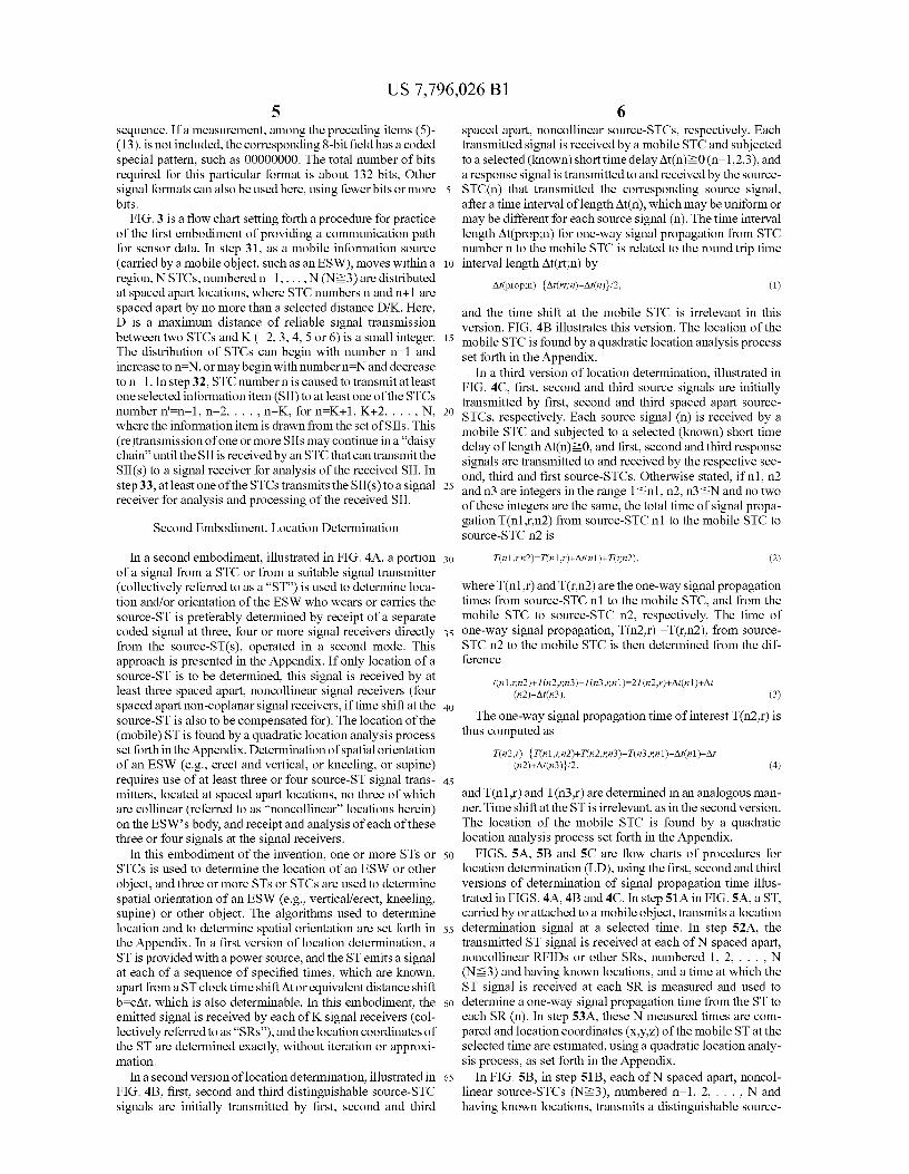
40 transmit the data. FIG. 2 illustrates a suitable format for anIn a first embodiment of the invention, illustrated in FIG. 1, RFID signal RFIDS-1 that can be used for transmitting data
an emergency service worker ("ESW") drops or otherwise between the source-RFID and the C&C sub-system. An initialpositions a sequence of N RFIDs 11-n (n=1, ... , N) or other block of 8 bits (or more, if desired) optionally includes pre-suitable signal transceivers (collectively referred to as amble bits (e.g., 7E or 01111110), followed by: (1) 8 bits that"STCs"), having nearest neighbor distances of no more than 45 identify the source-RFID by number (e.g., n-0-255); (2) 12the active communication range for presently available ver- bits that indicate the date and time (to the nearest sec) thesions of the STCs (e.g., about 23 feet for one version of an RFID signal is initially sent by the source-RFID; (3) 8 bitsRFID) as the ESW moves toward or within an incident site 13
that identify the RFID (no.) that last (received or generated
having an extreme environment. The STCs are preferably and) transmitted this signal (the source-RFID or an intenne-configured to communicate with each other in an ordered 5o diate RFID in the chain of signal passage); (4) 16 coded bitssequence, with built in redundancy, and with a command and used to determine or estimate the location and/or spatial ori-control ("C&C") sub-system 15 nearby. entation of the ESW who wears or carries the source-RFID;
For example, where a sequence of N STCs, numbered n-
(5) 8 bits indicating the estimated temperature at the source-1, ... , N, are used (N?3), device number n (?3) communi- RFID location; (6) 8 bits indicating the estimated pressure atcates with devices number n-2, n-1, n+1 and n+2 and thus 55 the source-RFID location; (7) 8 bits indicating the estimatedreceives and/or provides redundant information with devices concentration of a specified chemical or compound at then-2 and n-1, and receives and/or provides redundant infor- source-RFID location (more than one concentration can bemation with devices number n+1 and n+2. This redundancy transmitted); (8) 8 bits indicating the estimated electromag-allows STC device number n to communicate information to netic field intensity at the source-RFID location; (9) 8 bitsSTC device number n-2, even if device number n-1 is inop- 60 indicating a visible light index at the source-RFID location;erative. This second order redundancy can be extended to Kth
(10) 8 bits indicating an average noise intensity at the source-
order redundancy (K?2), whereby STC device number n
RFID location; (11) 8 bits indicating a peak noise intensity atreceives and/or provides redundant information with devices the source-RFID location; (12) 8 bits estimating the flux ofn—K, n-(K-1), ... , n-2, n-1, and receives and/or provides nuclear particles (alphas, betas, gammas and/or ions) at theredundant information with devices n+1, n+2, ... , n+(k-1), 65 source-RFID location; (13) 8 bits indicating the estimatedn+K, with a corresponding reduction in probability that a oxygen content at the source-RFID location; and (14) an 8-bitsignal received or generated at device number n will not be pattern (e.g., 10000001) representing a post-amble or closing
US 7,796,026 B15
sequence. If a measurement, among the preceding items (5)-(13), is not included, the corresponding 8-bit field has a codedspecial pattern, such as 00000000. The total number of bitsrequired for this particular format is about 132 bits, Othersignal formats can also be used here, using fewer bits or morebits.
FIG. 3 is a flow chart setting forth a procedure for practiceof the first embodiment of providing a communication pathfor sensor data. In step 31, as a mobile information source(carried by a mobile object, such as an ESW), moves within aregion, N STCs, numbered n=1, ... , N (N?3) are distributedat spaced apart locations, where STC numbers n and n+1 arespaced apart by no more than a selected distance D/K. Here,D is a maximum distance of reliable signal transmissionbetween two STCs and K (=2, 3, 4, 5 or 6) is a small integer.The distribution of STCs can begin with number n=1 andincrease to n=N, or may begin with number n=N and decreaseto n=1. In step 32, STC number n is caused to transmit at leastone selected information item (SII) to at least one of the STCsnumber n'=n-1, n-2, ... , n-K, for n=K+1, K+2, ... , N,where the information item is drawn from the set of SIIs. This(re)transmission of one or more SIIs may continue in a "daisychain" until the SII is receivedby an STC that can transmit theSII(s) to a signal receiver for analysis of the received SII. Instep 33, atleast one ofthe STCs transmits the SII(s) to a signalreceiver for analysis and processing of the received SII.
Second Embodiment. Location Determination
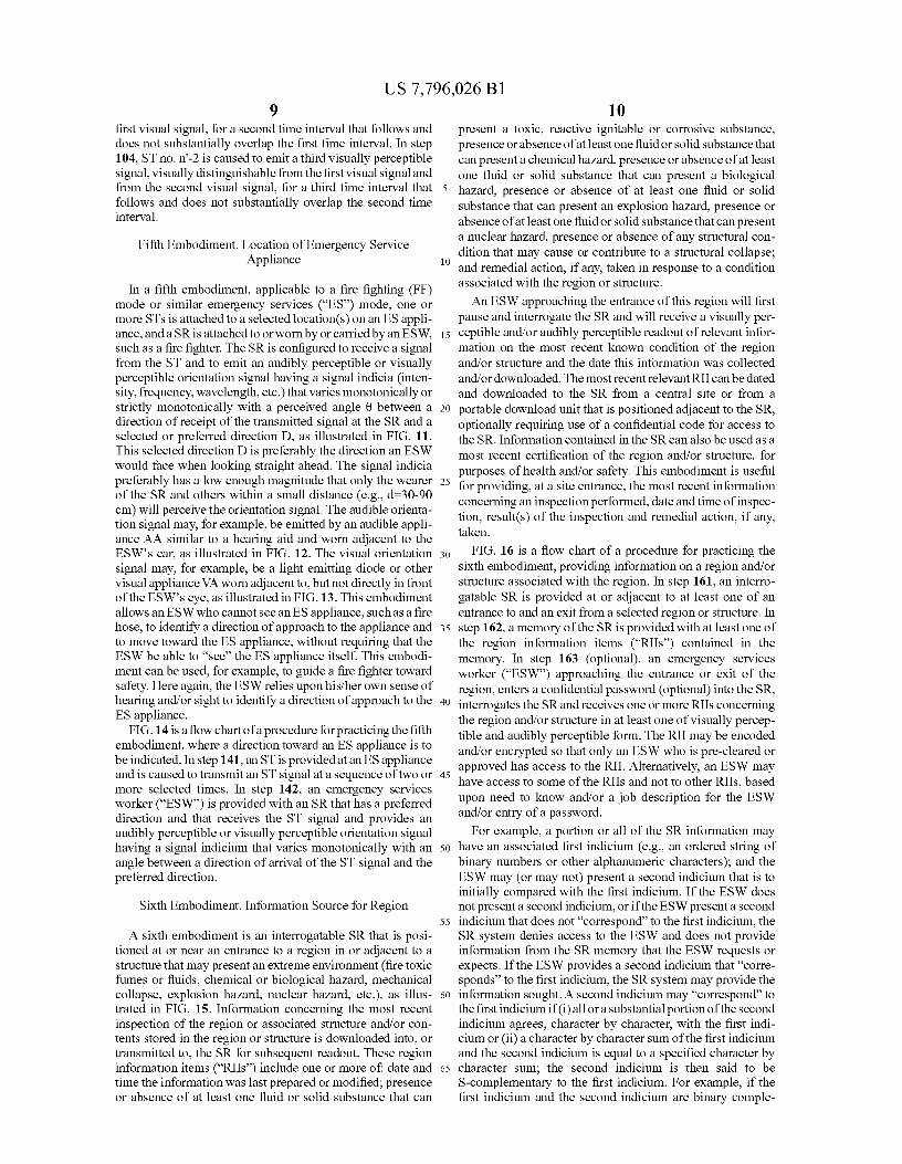
In a second embodiment, illustrated in FIG. 4A, a portionof a signal from a STC or from a suitable signal transmitter(collectively referred to as a "ST") is used to determine loca-tion and/or orientation of the ESW who wears or carries thesource-ST is preferably determined by receipt of a separatecoded signal at three, four or more signal receivers directlyfrom the source-ST(s), operated in a second mode. Thisapproach is presented in the Appendix. If only location of asource-ST is to be determined, this signal is received by atleast three spaced apart, noncollinear signal receivers (fourspaced apart non-coplanar signal receivers, if time shift at thesource-ST is also to be compensated for). The location of the(mobile) ST is found by a quadratic location analysis processset forth intheAppendix. Determination of spatial orientationof an ESW (e.g., erect and vertical, or kneeling, or supine)requires use of at least three or four source-ST signal trans-mitters, located at spaced apart locations, no three of whichare collinear (referred to as "noncollinear" locations herein)on the ES W's body, and receipt and analysis of each of thesethree or four signals at the signal receivers.
In this embodiment of the invention, one or more STs orSTCs is used to determine the location of an ESW or otherobject, and three or more STs or STCs are used to determinespatial orientation of an ESW (e.g., vertical/erect, kneeling,supine) or other object. The algorithms used to determinelocation and to determine spatial orientation are set forth inthe Appendix. In a first version of location determination, aST is provided with a power source, and the ST emits a signalat each of a sequence of specified times, which are known,apart from a ST clock time shift At or equivalent distance shiftb-cAt, which is also determinable. In this embodiment, theemitted signal is received by each of K signal receivers (col-lectively referred to as "SRs"), and the location coordinates ofthe ST are determined exactly, without iteration or approxi-mation.
In a second version of location determination, illustrated inFIG. 413, first, second and third distinguishable source-STCsignals are initially transmitted by first, second and third
6spaced apart, noncollinear source-STCs, respectively. Eachtransmitted signal is received by a mobile STC and subjectedto a selected (known) short time delay At(n)? 0 (n1,2,3), anda response signal is transmitted to and received by the source-
5 STC(n) that transmitted the corresponding source signal,after a time interval of length At(n), which may be uniform ormay be different for each source signal (n). The time intervallength At(prop;n) for one-way signal propagation from STCnumber n to the mobile STC is related to the round trip time
10 interval length At(rt;n) by
At(prop;n)={At(rt;n)-At(n)}/2, (1)
and the time shift at the mobile STC is irrelevant in thisversion. FIG. 4B illustrates this version. The location of the
15 mobile STC is found by a quadratic location analysis processset forth in the Appendix.
In a third version of location determination, illustrated inFIG. 4C, first, second and third source signals are initiallytransmitted by first, second and third spaced apart source-
20 STCs, respectively. Each source signal (n) is received by amobile STC and subjected to a selected (known) short timedelay of length At(n) i-0, and first, second and third responsesignals are transmitted to and received by the respective sec-ond, third and first source-STCs. Otherwise stated, if nl, n2
25 and n3 are integers in the range 1 - ^ : nl, n2, n3 - ': N and no twoof these integers are the same, the total time of signal propa-gation T(nl,r,n2) from source-STC nl to the mobile STC tosource-STC n2 is
30 T(nl,rn2)=T(nl,r)+At(nl)+T(rn2), (2)
where T(nl,r) and T(r,n2) are the one-way signal propagationtimes from source-STC nl to the mobile STC, and from themobile STC to source-STC n2, respectively. The time of
35 one-way signal propagation, T(n2,r) =T(r,n2), from source-STC n2 to the mobile STC is then determined from the dif-ference
t(nl,rn2)+T(n2,rn3)-T(n3,rn1)=2T(n2,r) +At(nl)+At(n2)-At(n3). (3)
40
The one-way signal propagation time of interest T(n2,r) isthus computed as
T(n2,r)={T(nl,rn2)+T(n2,rn3)-T(n3,rn1)- At(nl)-At(n2)+At(n3)}12, (4)
45
and T(nl,r) and T(n3,r) are determined in an analogous man-ner. Time shift at the ST is irrelevant, as in the second version.The location of the mobile STC is found by a quadraticlocation analysis process set forth in the Appendix.
50 FIGS. 5A, 5B and 5C are flow charts of procedures forlocation determination (LD), using the first, second and thirdversions of determination of signal propagation time illus-trated in FIGS. 4A, 4B and 4C. In step 51A in FIG. 5A, a ST,carried by or attached to a mobile object, transmits a location
55 determination signal at a selected time. In step 52A, thetransmitted ST signal is received at each of N spaced apart,noncollinear RFIDs or other SRs, numbered 1, 2, ... , N(N-3) and having known locations, and a time at which theST signal is received at each SR is measured and used to
60 determine a one-way signal propagation time from the ST toeach SR (n). In step 53A, these N measured times are com-pared and location coordinates (x,y,z) of the mobile ST at theselected time are estimated, using a quadratic location analy-sis process, as set forth in the Appendix.
65 In FIG. 513, in step 5113, each of N spaced apart, noncol-linear source-STCs (N?3), numbered n=1, 2, ... , N andhaving known locations, transmits a distinguishable source-
US 7,796,026 B17
8STC signal, number n. In step 5213, each of these source-STC
ence plane, as discussed in the Appendix. In step 72, the
signals (n) is received by a mobile STC that is attached to or system applies a "quadratic orientation analysis process," as
carried by a mobile object, and after a selected time delay set forth in the Appendix, to estimate the orientation param-
At(n)-_0, the mobile STC transmits a distinguishable eters (a, P,y,p) atone or more subsequent times. Instep 73, theresponse signal, number n. In step 5313, source-STC number 5 system optionally compares one or more of the initial orien-
n receives the response signal number n and determines a time tation parameters (a,PO,y0,p0) with corresponding param-
of one-way signal propagation between the source-STC num- eters among the subsequent orientation parameter(s) (a, (3,y,
ber n and the mobile STC, as in Eq. (1). In step 5413, these N
p), in order to estimate or represent change(s) in the
signal propagation times are compared and an estimate is orientation parameters, for example with passage of time.made of the location coordinates (x,y,z) of the mobile STC, io
using a quadratic location analytic process, as set forth in the Fourth Embodiment. Indication of Escape Route
Appendix.
In FIG. 5C, in step 51C, each of N spaced apart, noncol- In a fourth embodiment, a sequence of STs, located
linear source-STCs, numbered n=1, 2, ... , N (N-_3) and approximately according to a plan, can serve as an escape
having known locations, transmits a distinguishable source- 15 route for an ESW who is attempting to exit from an incident
STC signal, number n. In step 52C, each of these source-STC site that is part of an extreme environment. Each of the
signals (n) is received by a mobile STC that is attached to or sequence of STs is switched to a third mode of operation,
carried by a mobile object, and after a selected time delay whereby each ST emits a distinguishable, visibly and/or audi-
At(n), the mobile STC transmits a distinguishable response bly perceptible signal at each of a sequence of selected times,
signal (n). In step 53C, response signals numbernl, n2 and n3 20 as illustrated in FIG. 8. The signal emission times for two
are received at source transceivers number n2, n3 and nl, adjacent STs are spaced apart by a selected time interval of
respectively, where nl, n2 and n3 are integers satisfying length at least At(min) =0.2-2 sec, or longer if desired, so that
nl;-n2;-n3;-nl and l- :^nl, n2, n3- : N, and times ofpropaga- visual or audible confusion is avoided. Here, the ESW relies
tion, T(nl,r,n2), T(n2,r,n3) and T(n3,r,nl), are determined upon his/her own sense of hearing and/or sight to identify and
from source-STC nl to the mobile-STC to source-STC n2, 25 follow the escape route.
from source-STC n2 to the mobile-STC to source transceiver Where audible signals are used, each of the sequence of
n3, and from sourc-STCn3 to the mobile-STC to source-STC
STs emits a signal having a separate, audibly distinguishable
nl, respectively. In step 54C, elapsed times for one-way sig- frequency. In one version, the sequence of signal frequencies
nal propagation, T(nl,r,n2), T(n2,r,n3) and T(n3,r,nl)
is monotonically increasing as the ST sequence numberbetween the respective source-STCs nl, n2 and n3 and the 3o n (=1, ... , N) decreases and the ST path or direction leads the
mobile transceiver are determined, as in Eqs. (2), (3) and (4). ESW away from the incident site toward an exit and/or rela-
In step 55C, location coordinates of the mobile STC are tive safety. In a second version, the sequence of signal fre-
estimated, based upon a comparison of the one-way signal quencies is monotonically decreasing as the ST sequence
propagation times T(nl,r), T(n2,r) and T(0,r), using a qua- number n (=1, ... , N) decreases.
dratic location analysis process, as set forth in the Appendix. 35 Where visual signals are used, the wavelengths emitted by
Provision of LD signal sources and determination of their the separate STs should be visually distinguishable, which
(known) locations outside a structure is not usually a prob- will limit the number of wavelengths used to no more than
lem, although a small time interval (e.g., several minutes) about five. In one version, three visually distinguishable
may be required for this task. Provision of LD signal sources wavelengths, red, green and blue, are used in a repeatingwith known locations inside a structure may be implemented 40 pattern for the signals emitted by the sequence of STs: red,
by placing these sources at structure entrances and exits, green, blue, red, green, blue, red, green, ... , as the ST no.
where the coordinates of such a location can be determined
decreases and the ST path or direction leads the ESW awayusing "outside" LD sources as a first step. from the incident site toward an exit and/or relative safety.
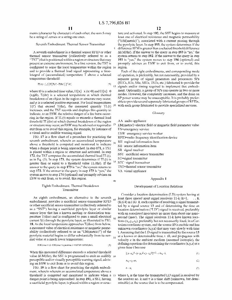
FIG. 9 is a flow chart of a procedure for practicing theThird Embodiment. Spatial Orientation 45 fourth embodiment. In step 91, N spaced apart STs, indexed
Determination
n=1, , N (N-_3) are distributed in a region, beginning with STnumber N at an initial location and indicating a path or direc-
Where spatial orientation of an object, such as an ESW or tion from the initial location n in the general direction of the
an appliance used in responding to the emergency, is to be exit. In step 92, ST no. n' (n'^3) is caused to emit a firstdetermined, three or more spaced apart, noncollinear STCs 5o audibly perceptible signal for a first time interval. In step 93,
are positioned on the object, and the location of each STC is
ST no. n'-1 is caused to emit a second audibly perceptible
determined, for example by the first version or the second
signal, audibly distinguishable from the first audible signal,
version or the third version discussed in the preceding three
for a second time interval that follows and does not substan-
paragraphs. Geometric analysis is then used to determine a tially overlap the first time interval. In step 94, ST no. n'-2 isplane defined by three or more STC locations and to deter- 55 caused to emit a third audibly perceptible signal, audibly
mine the spatial orientation of the object, as discussed in the
distinguishable from the first audible signal and from theAppendix and illustrated in FIG. 6. second audible signal, for a third time interval that follows
FIG. 7 is a flow chart of a procedure for estimating spatial and does not substantially overlap the second time interval.
orientation of a mobile object. In step 71, the system specifies
FIG. 10 is a flow chart of another procedure for practicingan initial or reference plane HO whose spatial orientation is to 60 the fourth embodiment. In step 101, N spaced apart STs,
be monitored, for example, by specifying: (1) initial or refer- indexed n=1, ... , N (N-13) are distributed in a region,
ence locations or location coordinates of M STs or STCs
beginning with ST number N at an initial location and indi-
(M-_3), spaced apart, noncollinear, located on or adjacent to cating a path or direction from the initial location in the
the object, and defining the plane HO; or (2) one or more general direction of the exit. In step 102, ST no. n' (n'-_3) isinitial or reference direction cosines and/or a displacement 65 caused to emit a first visually perceptible signal for a first time
distance (a0, PO,y0,p0) (referred to collectively as the "initial
interval. In step 103, ST no. n'-1 is caused to emit a second
orientation parameters") that also define the initial or refer- visually perceptible signal, visually distinguishable from the
US 7,796,026 B19
first visual signal, for a second time interval that follows anddoes not substantially overlap the first time interval. In step104, ST no. n'-2 is caused to emit a third visually perceptiblesignal, visually distinguishable from the first visual signal andfrom the second visual signal, for a third time interval thatfollows and does not substantially overlap the second timeinterval.
Fifth Embodiment. Location of Emergency ServiceAppliance
In a fifth embodiment, applicable to a fire fighting (FF)mode or similar emergency services ("ES") mode, one ormore STs is attached to a selected locations) on an ES appli-ance, and a SR is attached to or worn by or carried by an ESW,such as a fire fighter. The SR is configured to receive a signalfrom the ST and to emit an audibly perceptible or visuallyperceptible orientation signal having a signal indicia (inten-sity, frequency, wavelength, etc.) that varies monotonically orstrictly monotonically with a perceived angle 0 between adirection of receipt of the transmitted signal at the SR and aselected or preferred direction D, as illustrated in FIG. 11.This selected direction D is preferably the direction an ESWwould face when looking straight ahead. The signal indiciapreferably has a low enough magnitude that only the wearerof the SR and others within a small distance (e.g., d=30-90cm) will perceive the orientation signal. The audible orienta-tion signal may, for example, be emitted by an audible appli-ance AA similar to a hearing aid and worn adjacent to theESW's ear, as illustrated in FIG. 12. The visual orientationsignal may, for example, be a light emitting diode or othervisual appliance VA worn adjacent to, but not directly in frontof the ESW's eye, as illustrated in FIG. 13. This embodimentallows an ESW who cannot see an ES appliance, such as a firehose, to identify a direction of approach to the appliance andto move toward the ES appliance, without requiring that theESW be able to "see" the ES appliance itself. This embodi-ment can be used, for example, to guide a fire fighter towardsafety. Here again, the ESW relies upon his/her own sense ofhearing and/or sight to identify a direction of approach to theES appliance.
FIG. 14 is allow chart of a procedure for practicing the fifthembodiment, where a direction toward an ES appliance is tobe indicated. In step 141, an ST is provided at an ES applianceand is caused to transmit an ST signal at a sequence of two ormore selected times. In step 142, an emergency servicesworker ("ESW") is provided with an SR that has a preferreddirection and that receives the ST signal and provides anaudibly perceptible or visually perceptible orientation signalhaving a signal indicium that varies monotonically with anangle between a direction of arrival of the ST signal and thepreferred direction.
Sixth Embodiment. Information Source for Region
A sixth embodiment is an interrogatable SR that is posi-tioned at or near an entrance to a region in or adjacent to astructure that may present an extreme environment (fire toxicfumes or fluids, chemical or biological hazard, mechanicalcollapse, explosion hazard, nuclear hazard, etc.), as illus-trated in FIG. 15. Information concerning the most recentinspection of the region or associated structure and/or con-tents stored in the region or structure is downloaded into, ortransmitted to, the SR for subsequent readout. These regioninformation items ("RIIs") include one or more of. date andtime the information was last prepared or modified; presenceor absence of at least one fluid or solid substance that can
10present a toxic, reactive ignitable or corrosive substance,presence or absence of at least one fluid or solid substance thatcan present a chemical hazard, presence or absence of at leastone fluid or solid substance that can present a biological
5 hazard, presence or absence of at least one fluid or solidsubstance that can present an explosion hazard, presence orabsence of at least one fluid or solid substance that canpresenta nuclear hazard, presence or absence of any structural con-dition that may cause or contribute to a structural collapse;
10 and remedial action, if any, taken in response to a conditionassociated with the region or structure.
An ESW approaching the entrance of this region will firstpause and interrogate the SR and will receive a visually per-
15 ceptible and/or audibly perceptible readout of relevant infor-mation on the most recent known condition of the regionand/or structure and the date this information was collectedand/or downloaded. The most recent relevant RII can be datedand downloaded to the SR from a central site or from a
20 portable download unit that is positioned adjacent to the SR,optionally requiring use of a confidential code for access tothe SR. Information contained in the SR can also be used as amost recent certification of the region and/or structure, forpurposes of health and/or safety. This embodiment is useful
25 for providing, at a site entrance, the most recent informationconcerning an inspection performed, date and time of inspec-tion, result(s) of the inspection and remedial action, if any,taken.
30 FIG. 16 is a flow chart of a procedure for practicing thesixth embodiment, providing information on a region and/orstructure associated with the region. In step 161, an interro-gatable SR is provided at or adjacent to at least one of anentrance to and an exit from a selected region or structure. In
35 step 162, a memory of the SR is provided with at least one ofthe region information items ("RIIs") contained in thememory. In step 163 (optional), an emergency servicesworker ("ESW") approaching the entrance or exit of theregion, enters a confidential password (optional) into the SR,
40 interrogates the SR and receives one or more RIIs concerningthe region and/or structure in at least one of visually percep-tible and audibly perceptible form. The RII may be encodedand/or encrypted so that only an ESW who is pre-cleared orapproved has access to the RII. Alternatively, an ESW may
45 have access to some of the RIIs and not to other RIIs, basedupon need to know and/or a job description for the ESWand/or entry of a password.
For example, a portion or all of the SR information may50 have an associated first indicium (e.g., an ordered string of
binary numbers or other alphanumeric characters); and theESW may (or may not) present a second indicium that is toinitially compared with the first indicium. If the ESW doesnot present a second indicium, or if the ESW present a second
55 indicium that does not "correspond" to the first indicium, theSR system denies access to the ESW and does not provideinformation from the SR memory that the ESW requests orexpects. If the ESW provides a second indicium that "corre-sponds" to the first indicium, the SR system may provide the
60 information sought. A second indicium may "correspond" tothe first indicium if (i) all or a substantial portion of the secondindicium agrees, character by character, with the first indi-cium or (ii) a character by character sum of the first indiciumand the second indicium is equal to a specified character by
65 character sum; the second indicium is then said to beS-complementary to the first indicium. For example, if thefirst indicium and the second indicium are binary comple-
US 7,796,026 B111
ments (character by character) of each other, the sum S maybe a string of zeroes or a string one ones.
Seventh Embodiment. Thermal Sensor Transmitter
A seventh embodiment is a thermal sensor RFID or otherthermal sensor transmitter (collectively referred to as a"TST") that is positioned within a region or structure that maypresent an extreme environment. In a first version, the TST isconfigured to sense the local temperature within the regionand to provide a thermal load signal representing a time-integral of (accumulated) temperature T above a selectedtemperature threshold:
TL(t)=ft,`{H{T(P)—T(thr)llpdt', (5)
where tO is a selected time value, H{x}=x (x>O) and H{x}-0(x-_0), T(thr) is a selected temperature at which thermalbreakdown of an object in the region or structure may occur,and p is a selected positive exponent. For local temperaturesT(t') that exceed T(thr), the measured quantity TL(t)increases, and the TST records and displays this quantity toindicate, to an ESW, the relative danger of a fire burst occur-ring in the region. If TL(t) equals or exceeds a thermal loadthreshold TL(thr) at which thermal breakdown of the regionor structure may occur, an ESW may be advised orrequired toexit from or to avoid this region, for example, by issuance ofa visual and/or audible warning signal.
FIG. 17 is a flow chart of a procedure for practicing theseventh embodiment, wherein an accumulated temperatureabove a threshold is computed and monitored to indicatewhen a danger point is being approached. In step 171, a TSTis placed within a region or structure and activated. In step172, the TST computes the accumulated thermal load TL(t),as in Eq. (5). In step 173, the system determines if TL(t) isgreater than or equal to a threshold value TL(thr). If theanswer to the query in step 173 is "no," the system returns tostep 172. If the answer to the query in step 173 is "yes," thesystem moves to step 174 (optional) and promptly advises anESW to exit from, or to avoid, this region.
12ture and activated. In step 192, the SST begins to measure atleast one of electrical resistance and magnetic permeability("EM(metric)"), associated with a current passing throughthe pyrolytic layer. In step 193, the system determines if the
5 difference AEM is greater than a selected threshold differenceAEM(thr). If the answer to the query in step 193 is "no," thesystem returns to step 192. If the answer to the query in step193 is "yes," the system moves to step 194 (optional) andpromptly advises an ESW to exit from, or to avoid, this
io region.Each of the eight embodiments, and corresponding mode
of operation, is preferably, but not necessarily, provided by aseparate group of signal generators and processors SPs(STCs, STs, SRs, SSTs, TSTs, etc.) fabricated to provide the
15 signals and/or timing required to implement that embodi-ment. Optionally, a group of SPs can operate in two or moremodes. However, the complexity increases, and the drain onSP power source may be unacceptable. It is probably prefer-able to provide several separately fabricated groups of RFIDs,
20 with each group fabricated to provide specialized services.
Glossary
AA—audio appliance25 EM(metric) —electric field or magnetic field parameter value
ES—emergency serviceESW—emergency service workerRFID=radio frequency identification device
30 RII=regional information itemSII=sensor information itemSR—signal receiverSST—sacrificial sensor transmitterST—signal transmitter
35 STC=signal transceiverTST—thermal sensor transmitterVA—visual appliance
40Appendix 1
Eighth Embodiment. Thermal Breakdown Development of Location RelationsTransmitter
An eighth embodiment, an alternative to the seventhembodiment, provides a sacrificial sensor-transmitter RFIDor other sacrificial sensor-transmitter (collectively referred toas a "SST") having a sacrificial pyrolytic layer or similarsensor layer that has a known melting or dissociation tem-perature T(diss) and is configured to pass a small electricalcurrent I(t) through the pyrolytic layer, as illustrated in FIG.18. As the local temperature approaches T(diss) from below,a measured value of electrical resistance or magnetic perme-ability (collectively referred to as an "EM(metric)") of thepyrolytic material begins to differ substantially from its nor-mal value at a much lower temperature:
IEM(metric)—EM(metric;normal)1=AEM>AEM(thr). (6)
When this measured difference exceeds a selected thresholdvalue AEM(thr), the SST is programmed to emit an audiblyperceptible and/or visually perceptible warning signal, advis-ing an ESW to exit from or to avoid this region.
FIG. 19 is a flow chart for practicing the eighth embodi-ment, wherein wherein an accumulated temperature above athreshold is computed and monitored to indicate when adanger point is being approached. In step 191, a SST, havinga sacrificial pyrolytic layer, is placed within a region or struc-
Consider a location determination (LD) system having at
45 least three spaced apart signal receivers I I-k (k=1, ... , K(K-4) in FIG. 1, each capable of receiving a signal transmit-ted by a signal source 13 and of determining the time anlocation determination ("LD") signal is received, preferablywith an associated inaccuracy no more than about one nano-
50 second (nsec). The signal receivers I I-k have known loca-tions (xk,yk,z,), preferably but not necessarily fixed, in a Car-tesian coordinate system, and the source 13 is mobile and hasunknown coordinates (x,y,z) that may vary slowly with timet. Assuming that the LD signal is transmitted by the source 13
55 at a known or determinable time, t=tO, and propagates withvelocity c in the ambient medium (assumed isotropic), thedefining equations for determining the coordinates (x,y,z) at agiven time t become
L(x-xk)Z+('-yk)2+(Z-Zk)2]"2 —c Atk b, (1)60
Atk tk t01 (2)
b —cc, (3)
65 where tk is the time the transmitted LD signal is received bythe receiver no. k and ti is a time shift (unknown, but deter-minable) at the source that is to be compensated.
US 7,796,026 B113 14
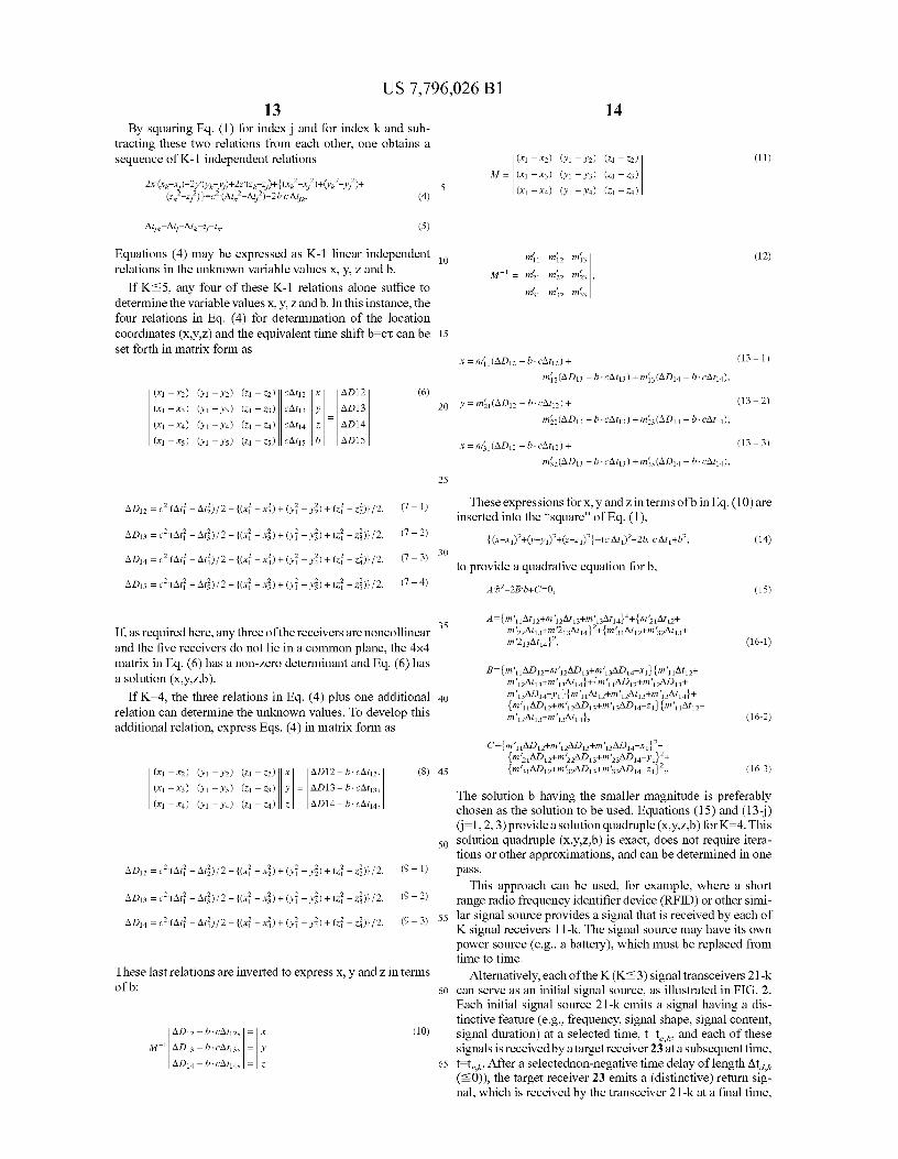
By squaring Eq. (1) for index j and for index k and sub-tracting these two relations from each other, one obtains asequence of K-1 independent relations (XI - x2) (Y1 - Y2) (Zl - Z2)
//'''' //''''(XI -x3) (Yl - Y3) (Zl -Z3)
2x'(xk xj)+2Y V'k Yj)+2Z (Zk Zj)+ {(xk -x/)+V'k -Yj2)+5ZZ 2)}=c2 (Atk -Atj2)-2b c Atj,, (4) (xt - x4) (Yt - Y4) (Zt - Zq)k - j
Atjk Atj-At7, ,,-tk. (5)
Equations (4) may be expressed as K-1 linear independent 10 mil m. mi3
relations in the unknown variable values x, y, z and b.M = m21 M22 mi3
If K-5, any four of these K-1 relations alone suffice to m m m31 32 33determine the variable values x, y, z and b. In this instance, thefour relations in Eq. (4) for determination of the locationcoordinates (x,y,z) and the equivalent time shift b -CT can be 15
set forth in matrix form as
(11)
(12)
(X I — x2) (Y1 — Y2) (Zl — Z2) CA42 x AD12 (6)
(XI -x3) (Y1 - Y3) (Zl - Z3) CAt13 Y AD 13
(X I — x4) (Y1 — Y4) (Zl — Z4) CA4 4 Z AD14
(XI -x5) (Y1 - Y5) (Z1 -Z5) CA4 5 b AD15
AD12 =c2'(Ar1 —At22)l 2—{(xi —x
z)+(Yi — Yz)+(Zi — Z2)}l 2, (7-1)
x=mi1 (AD 12 —b CAt12)+ (13-1)
mi2(AD13 — b CAt13) + m11 3 (AD 14 — b CAt14),
20 Y = m21(AD12 - b CA42) + (13-2)
m22(AD 13 — b CA 43) + m23 (AD14 — b CA44),
x=m31(AD12-b CA42)+ (13-3)
m32(AD 13 — b CA 43) + m33 (AD14 — b CA44),
25
These expressions for x, y and z in terms of b in Eq. (10) areinserted into the "square" of Eq. (1),
AD13=c2'(Ar1—At3)/2—{(xi—xs)+(Yi—Ys) +(Zi— Z3) }/2, (7-2) x 2+ +z —c —.c+b2, (14){(x- 1) V'-Yl) (z- 1) }-( At 1) 2bAt 1
AD14 =ca (Art —At4) l 2—{ (xi —x
a) +(Yi — Y2)+(Zi — Z4)}l 2, (7-3) 30
to provide a quadrative equation for b,AD15 =c2 (At1 —At52)l 2—
{(xi —xs)+(Yi — Ys)+(Zi — ZS)}l 2, (7-4)
If, as required here, any three of the receivers are noncollinear 35
and the five receivers do not lie in a common plane, the 4x4matrix in Eq. (6) has a non-zero determinant and Eq. (6) hasa solution (x,y,z,b).
If K=4, the three relations in Eq. (4) plus one additional 40
relation can determine the unknown values. To develop thisadditional relation, express Eqs. (4) in matrix form as
These last relations are inverted to express x, y and z in termsof b:
AD12 =c2'(Ar1 —At22)l 2—{(xi —x
z)+(Yi — Yz)+(Zi — Z2)}l 2, (9-1)
AD13 =c2 (At1 —At3)l 2—{(xi —x
s)+(Yi — Ys)+(Zi — Z3) }l 2, (9-2)
AD14 =ca (Art —At4)/ 2—{(xi —x
a)+(Yi — Y2)+(Zi — Z4)}/ 2, (9-3)
AD12—b-cAgy
TZ
(10)
/V/ 1 AD13 -b -CAt13,
AD14 - b - CAt14,
(xl —x2) (Y1 — Y2) (Z1 —Z2) x AD12—b-CA42 , (8) 45
(xl —x3) (Yl - Y3) (zl - z3) Y = AD13—bcAr13, The solution b having the smaller magnitude is preferably
(xl —x4) (Yl - Y4) (zl - z4) z
AD14—bcA44,chosen as the solution to be used. Equations (15) and (13 j)0-1, 2, 3) provide a solution quadruple (x,y,z,b) for K=4. This
50 solution quadruple (x,y,z,b) is exact, does not require itera-tions or other approximations, and can be determined in onepass.
This approach can be used, for example, where a shortrange radio frequency identifier device (RFID) or other simi-
55 lar signal source provides a signal that is received by each ofK signal receivers 11-k. The signal source may have its ownpower source (e.g., a battery), which must be replaced fromtime to time.
Alternatively, each of the K (K-3) signal transceivers 21-k60 can serve as an initial signal source, as illustrated in FIG. 2.
Each initial signal source 21-k emits a signal having a dis-tinctive feature (e.g., frequency, signal shape, signal content,signal duration) at a selected time, t=te k, and each of thesesignals is received by a target receiver 23 at a subsequent time,
65 t=t,,,k, After a selectednon-negative time delay of length At,,,(-_0)), the target receiver 23 emits a (distinctive) return sig-nal, which is received by the transceiver 21-k at a final time,
A b2-2B b+C-0, (15)
A-{m'11At12+m'12At13+m'13At14]2+{m ZlAt12+m '22At13+m'213At14]2+ {m'31At12+m 32At13+m'2 13At14i2, (16-1)
B-{m '11 AD 12+m'12AD 13+m'13AD 14-xlI Lm'11At12+m'12At13+m'13AJt14}+{m'11AD12+m'12AD13+m'13AD14 Yl}Lm'11At12+m'12At13+m'J13At14}+{m '11 AD 12+m'12AD 13+m'13AD 14_Z 1} Lm'11At12+m'12At13+m'13At141, (16-2)
C-{m'11AD12+m'12AD13+m'13AD1a xl}2+{m 21AD 12+m'22AD 13+m z3AD 1a Y1 2+{m'31 AD 12+m 32AD 13+m 33AD14 Z 1 2 ' . (16-3)
US 7,796,026 B115
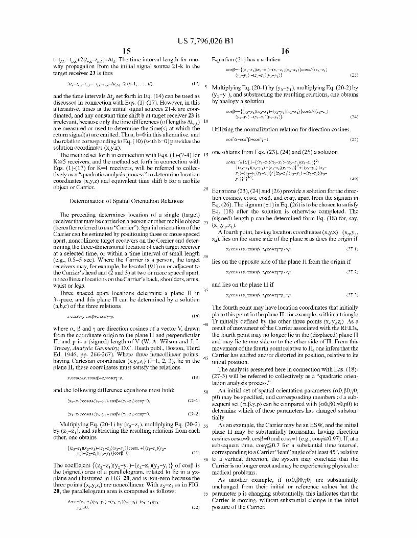
t=tfk.=te,k+2(t,,,k te,k)+Atk. The time interval length for one-way propagation from the initial signal source 21-k to thetarget receiver 23 is thus
16Equation (21) has a solution
CoS^/=/''''L(Z3-Zl)(X2 X1/')''-(Zz Zl 1)(X3 X1)1 CoSoTZ3-Z1)(Y2Yl) -(2 Zl)V'3-Y1)J (23)
Otk r k to k {tfx to k Otd k}12 (k-1, ... , K), (17)
and the time intervals Ark set forth in Eq. (14) can be used asdiscussed in connection with Eqs. (1)-(17). However, in thisalternative, times at the initial signal sources 21-k are coor-dinated, and any constant time shift b at target receiver 23 isirrelevant, because only the time differences (of lengths At,,,)are measured or used to determine the time(s) at which thereturn signal(s) are emitted. Thus, b=0 in this alternative, andthe relation corresponding to Eq. (10) (with b-0)provides thesolution coordinates (x,y,z).
The method set forth in connection with Eqs. (1)-(7-4) forK^5 receivers, and the method set forth in connection withEqs. (1)-(17) for K=4 receivers, will be referred to collec-tively as a "quadratic analysis process" to determine locationcoordinates (x,y,z) and equivalent time shift b for a mobileobject or Carrier.
Determination of Spatial Orientation Relations
The preceding determines location of a single (target)receiver that may be carried on a person or other mobile object(hereafter referred to as a "Carrier"). Spatial orientation of theCarrier can be estimated by positioning three or more spacedapart, noncollinear target receivers on the Carrier and deter-mining the three-dimensional location of each target receiverat a selected time, or within a time interval of small length(e.g., 0.5-5 sec). Where the Carrier is a person, the targetreceivers may, for example, be located (91) on or adjacent tothe Carrier's head and (2 and 3) at two or more spaced apart,noncollinear locations on the Carrier's back, shoulders, arms,waist or legs.
Three spaced apart locations determine a plane H in3-space, and this plane H can be determined by a solution(a,b,c) of the three relations
X Cosa+Y COS P+Z Cos", (18)
where a, R and y are direction cosines of a vector V, drawnfrom the coordinate origin to the plane H and perpendicularH, and p is a (signed) length of V (W. A. Wilson and J. I.Tracey, Analytic Geometry, D.C. Heath publ., Boston, ThirdEd. 1946, pp. 266-267). Where three noncollinear points,having Cartesian coordinates (x,y,,z,) (I=1, 2, 3), lie in theplane H, these coordinates must satisfy the relations
X, Cosa+Y Cosap+Z, Cosa", (19)
and the following difference equations must hold:
(XI-X .) Cosa+(Yz Y 1 ), COSP+(ZZ Z l ) COSY-0, (20-1)
(X3 X l )'COSa+(Y3 YA COSP+(Z3-Z l)'COSy-0. (20-2)
Multiplying Eq. (20-1) by (z 3 -z1 )1 multiplying Eq. (20-2)by (z2-z 1), and subtracting the resulting relations from eachother, one obtains
L(Z3 -Z 1)(X2_ X 1)-/('Z'2 Z 1) ll(X3} 3 zX 1) cosa, + L(Z Z1)(VYl)- (2 Zl)(Y3Y1)J COSP-O, (21)
The coefficient {(z3-z1)(Y2-Y1)-(z2-z1)(Y3-YJ1 of cos(3 isthe (signed) area of a parallelogram, rotated to lie in a yz-plane and illustrated in FIG. 20, and is non-zero because thethree points (x,,y,z,) are noncollinear. With z 2=z 1 as in FIG.20, the parallelogram area is computed as follows:
ArC3.-(Z3 -Z1)(Y3 Yl) -(Z3 Z 1)('2 Yl)- (Z2 Z l)V'3-Yrxo. (22)
5 Multiplying Eq. (20-1) by (Y 3 -Y0 1 multiplying Eq. (20-2) by(Y2-y 1), and substracting the resulting relations, one obtainsby analogy a solution
CoSV={(Y3 Y1)(X2_ X1)-(Yz Y 1 )(X3 -X 1)}cosaTZ3 Z1)(Y2 _Y1) -(ZZ Z 1)(Y3Y1)1 . (24)
10
Utilizing the normalization relation for direction cosines,
CoS2a+CoS2p+CoS2y-1, (25)
15 one obtains from Eqs. (23), (24) and (25) a solution
Cosa=(±1)1(1/+''2
Y((Z3 -Z l)(X2 Xll/ ))' '-' (ZZ Zl)(xff3/''
Xl) } 21ffL(Z3 -Zl)V'l) -(2J ZXY3 Yl)]2+ LV'3Y1) (X2X l)- (y2 Yl(X3 -X l)l l ((Z3 Z l)(Yz Yl) - (Z2 Z1)(Y3Y1)}2}
112(26)
20 Equations (23), (24) and (26) provide a solution for the direc-tion cosines, cosa, cosy, and cosy, apart from the signum inEq. (26). The signum (±1) in Eq. (26) is to be chosen to satisfyEq. (18) after the solution is otherwise completed. The
25 (signed) length p can be determined form Eq. (18) for, say,(xvYvzJ-
A fourth point, having location coordinates (x,Y,z) =(x41Y41Z4), lies on the same side of the plane a as does the origin if
X4 Cosa+Y4 COSUP+Z4 COSay p4 <p, (27-1)
30
lies on the opposite side of the plane H from the origin if
X4 Cosa+Y4 COSUP+Z4 cosay p4 >p, (27-2)
and lies on the plane H if35
X4 Cosa+Y4 COSUP+Z4 cosay p4p, (27-3)
The fourth point may have location coordinates that initiallyplace this point in the plane H, for example, within a triangle
40 Tr initially defined by the other three points (x,,y,,z,). As aresult of movement of the Carrier associated with the RFIDs,the fourth point may no longer lie in the (displaced) plane Hand may lie to one side or to the other side of H. From thismovement of the fourth point relative to H, one infers that the
45 Carrier has shifted and/or distorted its position, relative to itsinitial position.
The analysis presented here in connection with Eqs. (18)-(27-3) will be referred to collectively as a "quadratic orien-tation analysis process."
50 An initial set of spatial orientation parameters (a0,(30,y0,p0) may be specified, and corresponding members of a sub-sequent set (a,P,y,p) can be compared with (a0,(30,y0,p0) todetermine which of these parameters has changed substan-tially
55 As an example, the Carrier may be an ESW, and the initialplane H may be substantially horizontal, having directioncosines cosa-0, cosy-0 and cosy-1 (e.g., cosy?0.97). If, at asubsequent time, cosy-W.7 for a substantial time interval,corresponding to a Carrier "lean" angle of at least 45', relative
60 to a vertical direction, the system may conclude that theCarrier is no longer erect and may be experiencing physical ormedical problems.
As another example, if (a0,(30,y0) are substantiallyunchanged from their initial or reference values but the
65 parameter p is changing substantially, this indicates that theCarrier is moving, without substantial change in the initialposture of the Carrier.
US 7,796,026 B1
17Glossary
ESW—emergency services workerES (appliance) —emergency service appliance, used by an
ESW (e.g., a fire hose)AA—audio applianceVA—visual applianceEM(metric) —electrical field or magnetic field parameter
valueRFID radio frequency identification deviceST—signal transmitter, which transmits, but does not neces-
sarily receive, a signalSR—signal receiver, which receives but does not necessarily
transmitSTC—signal transceiver, which transmits and receives signalsTST=thermal sensor transmitter of at least one physical or
chemical quantity) that transmits and receivesSST—sacrificial sensor transmitter that transmits a signalSII=selected information item (examples in first embodi-
ment)RII=regional information item (examples in fifth embodi-
ment)
What is claimed is:1. A method for communicating information between a
mobile object and an information receiver source, the methodcomprising:
distributing a plurality of N radio frequency signal trans-ceiver devices ("STCs"), indexed as n=1, ... , N withN?3, as a mobile object moves within a region, wherethe STC numbers n and n+1 are spaced apart no furtherthan a selected distance D/K, where D is no greater thana maximum distance of reliable signal transmissionbetween two STCs and K is an integer selected from theintegers 11, 2, 3, 4, 51;
causing STC no. n to transmit at least one selected infor-mation item to at least one of STC nos. n' —n— 1, n-2, ... ,n—K, for n=K+1, K+2, ... , N, where the selectedinformation item is drawn from a group of items includ-ing STC no. for the original source of the information(referred to as the "source-STC"); location of thesource-STC that is presently transmitting the informa-tion; temperature at the source-STC location; pressure atthe source-STC location; concentration of a specifiedchemical or compound at the source-STC location; elec-tromagnetic field intensity at the source-STC location; avisible light index at the source-STC location; averagenoise intensity at the source-STC location; peak noiseintensity at the source-STC location; flux of nuclearparticles (alpha, beta, gamma and/or ion) at the source-STC location; and estimated oxygen content at thesource-STC location; and
causing at least one of the STCs no. 1, 2, ... , K to transmitthe at least one selected information item to a signalreceiver for analysis of the transmitted signal.
2. The method of claim 1, further comprising causing saidSTC no. n' that receives said at least one selected informationitem from said STC no. n to transmit said at least one selectedinformation item to at least one of said STC nos. n"=n'-1,n'-2, , n'—K.
3. The method of claim 1, further comprising choosing atleast one of said STCs to be a RFID.
4. A method for determining location of a non-stationaryobject, the method comprising:
providing a radio frequency signal transmitter ("ST") thatis attached to or carried by a non-stationery object;
causing the ST to transmit a ST signal at a selected time;
18receiving the transmitted ST signal at each of N spaced
apart, noncollinear radio frequency signal receivers("SRs") at known locations, and measuring an elapsedtime for propagation of a received signal from the ST to
5 each SR, with N?3; andestimating location coordinates for the ST, based upon
comparison of the measured elapsed times, using a qua-dratic location analysis process.
5. The method of claim 4, further comprising choosing at10 least one of said ST and said N STCs to be a RFID.
6. A method for determining location of a non-stationaryobject, the method comprising:
providing N spaced apart, noncollinear radio frequencysignal transceivers ("source-STCs") at known locations,
15 numbered n=1, ... , N, where source-STC no, n trans-mits a distinguishable first signal S1(n);
providing a mobile radio frequency signal transceiver("mobile STC") that is attached to or carried by a non-stationery object, where the mobile STC transmits a
20 second distinguishable signal S2(n), after a selectednon-negative time delay, in response to receipt of thefirst signal S (n), where source-STC no. n receives thesecond distinguishable signal S2(n) and measures anelapsed time between transmission of the first signal
25 S1(n) and receipt of the second signal S2(n); andestimating location coordinates for the mobile STC, based
upon comparison of the measured elapsed times andusing a quadratic location analysis process.
7. The method of claim 6, further comprising choosing at30 least one of said mobile STC and said N source-STCs to be a
RFID.8. A method for determining location of an non-stationary
object, the method comprising:providing at least three spaced apart, noncollinear radio
35 frequency signal transceivers ("source-STCs") atknownlocations, numbered n=n1, n2, n3, . . . withnl ;-n2;-n3;-nl, where source-STC no. n transmits a dis-tinguishable first signal S1(n);
providing a mobile radio frequency signal transceiver40 ("mobile STC") that is attached to or carried by a non-
stationery object, where the mobile STC: (i) receives asignal S1(nl) and, after a known time delay At(nl),transmits a distinguishable signal S2(nl) that is receivedby the STC number n2; (ii) receives a signal S 1(n2) and,
45 after a known time delay At(n2), transmits a distinguish-able signal S2(n2) that is received by the STC numbern3; and (iii) receives a signal S1(n3) and, after a knowntime delay At(n3), transmits a distinguishable signal
50S2(n3) that is received by the STC number n3;
estimating elapsed times, T(l,r), T(2,r) and T(3,r), for sig-nal propagation between the STC number nl and themobile STC, between the STC number n2 and themobile STC, and between the STC number n3 and the
55mobile STC, respectively; and
estimating location coordinates for the mobile STC, basedupon comparison of the measured elapsed times andusing a quadratic location analysis process.
9. The method of claim 8, further comprising choosing at60 least one of said mobile STC and said N source-STCs to be a
RFID.10. A method for determining spatial orientation of M
non-stationary objects, the method comprising:providing M radio frequency signal transmitters ("STs")
65 that are attached to or carried by the M non-stationeryobjects, numbered m=1, ... , M, at spaced apart, non-collinear positions, where ST no. m transmits a distin-
US 7,796,026 B1
19
20guishable ST signal at each of two or more selected
parameters (a,P,y,p) to determine a change, if any, in
spaced apart times and M?3; orientation of the plane II 2 with respect to said plane II,receiving each of the transmitted ST signals at each of N
15. The method of claim 13, further comprising choosing at
spaced apart radio frequency signal receivers ("SRs") at
least one of said mobile STCs and said source-STCs to be aknown locations, no three of which are collinear, and 5 RFID.measuring an elapsed time for propagation of a received
16. A method for indicating a path from an initial location
signal from each ST to each SR, with N?3;
in a region toward an exit from the region, the method com-estimating location coordinates for teach of the STs, based
prising:
upon comparison of the measured elapsed times, using a providing N spaced apart radio frequency signal transceiv-quadratic location analysis process; 10 ers ("STCs"), numbered n=1, ... , N with N?3, begin-
applying a quadratic orientation analysis process to the ning at an initial location in a region and defining a pathlocation coordinates for each of the STs to estimate
from the initial location toward, or in a direction of, an
orientation parameters (a, P,y,p) for a plane II defined by exit from the region;locations of at least three of the STs for a first selected
causing STC no. n' (n'?3) to emit a first audibly perceptible
time. 15 signal for a first time interval;11. The method of claim 10, further comprising: causing STC no. n'-1 to emit a second audibly perceptiblespecifying a reference plane H, that is defined by said
signal, which is audibly distinguishable from the first
orientation parameters (a,P,y,p) for said first selected
audible signal, for a second time interval that followstime; and does not substantially overlap the first time interval;
estimating orientation parameters (a',(3',y',p') for a second 20 andselected time that defines a second plane II2 , and
causing STC no. n'-2 to emit a third audibly perceptible
comparing at least one of the orientation parameters (a', (3', signal, which is audibly distinguishable from the firsty',p') with a corresponding one of said orientation audible signal and from the second audible signal, for aparameters (a,P,y,p) to determine a change, if any, in third time interval that follows and does not substantiallyorientation of the plane II2 with respect to said plane H,. 25 overlap the second time interval.
12.The method of claim 10, further comprising choosing at
17. The method of claim 16, further comprising choosingleast one of said M mobile STCs and said N source-STCs to said first, second and third audible signals to contain first,be a RFID. second and third frequencies that are audibly distinguishable
13. A method for determining spatial orientation of a non- from each other, where the second frequency is smaller thanstationary object, the method comprising: 30 the first frequency and the third frequency is smaller than the
providing N radio frequency signal source-transceivers second frequency.("source-STCs") that are spaced apart at known loca- 18. The method of claim 16, further comprising choosingtions, no three of which are collinear, numbered
said first, second and third audible signals to contain first,
n=1, ... , N (N?3), where source-STC no. n transmits a second and third frequencies that are audibly distinguishabledistinguishable signal SI(n); 35 from each other, where the second frequency is larger thanthe
providing M radio frequency signal mobile transmitters
first frequency and the third frequency is larger than the("mobile STCs"), numbered m=1, ... , M (M>3), that second frequency.are attached to or carried by a non-stationery object at
19. The method of claim 16, further comprising choosingspaced apart locations, no three of which are collinear, said first, second and third audible signals to have soundwhere each mobile STC receives each signal S (n) and, 40 intensities that are audibly distinguishable from each other,after a time delay of length At(n), transmits a distin- where the second sound intensity is smaller than the firstguishable mobile STC signal S2(n) at each of two or sound intensity and the third sound intensity is smaller thanmore selected spaced apart times, and where each signal
the second sound intensity.
S2(n) is received by at least one of the source-STCs; 20. The method of claim 16, further comprising choosing
determining at least one of (i) a time of propagation of the 45 said first, second and third audible signals to have soundsignal Sl(n) from the source-STC number n to the
intensities that are audibly distinguishable from each other,
mobile STC number m and (ii) a time of propagation of
where the second sound intensity is greater than the firstthe signal S2(n) from the mobile STC number m to the sound intensity and the third sound intensity is greater thansource-STC number n, for each source-STC number n the second sound intensity.and each mobile STC number m 50 21. Themethod of claim 16, further comprising choosing at
estimating location coordinates for each of the mobile
least one of said STCs to be a RFID.STCs, based upon comparison of the measured times of
22. A method for indicating a path from an initial location
signal propagation, using a quadratic location analysis
in a region toward an exit from the region, the method com-process; and
prising:applying a quadratic orientation analysis process to the 55 providing N spaced apart radio frequency signal transceiv-
location coordinates for each of the STCs to estimate ers ("STCs"), numbered n=1, ... , N with N?3, begin-orientation parameters (a, P,y,p) for a plane II defined by ning at an initial location in a region and defining a pathlocations of at least three of the STCs for a first selected
from the initial location toward an exit from the region;
time. causing STC no. n' (n'>3) to emit a first visually perceptible14. The method of claim 13, further comprising: 60 signal for a first time interval;specifying a reference plane H, that is defined by said
causing STC no. n'-1 to emit a second visually perceptible
orientation parameters (a,P,y,p) for said first selected
signal, which is audibly distinguishable from the firsttime; visual signal, for a second time interval that follows and
estimating orientation parameters (a',(3',y',p') for a second
does not substantially overlap the first time interval; andselected time that defines a second plane II2 , and
65 causing STC no. n'-2 to emit a third visually perceptible
comparing at least one of the orientation parameters (a', (3', signal, which is audibly distinguishable from the firsty',p') with a corresponding one of said orientation visual signal and from the second visual signal, for a
US 7,796,026 B121
third time interval that follows and does not substantiallyoverlap the second time interval.
23. The method of claim 22, further comprising choosingsaid first, second and third visual signals to contain first,second and third wavelengths that are visually distinguish-able from each other, where the second wavelength is smallerthan the first wavelength and the third wavelength is smallerthan the second wavelength.
24. The method of claim 22, further comprising choosingsaid first, second and third visual signals to contain first,second and third wavelengths that are visually distinguish-able from each other, where the second wavelength is greaterthan the first wavelength and the third wavelength is greaterthan the second wavelength.
25. The method of claim 22, further comprising choosingsaid first, second and third visual signals to contain first,second and third light intensities that are visually distinguish-able from each other, where the second light intensity issmaller than the first light intensity and the third light inten-sity is smaller than the second light intensity.
26. The method of claim 22, further comprising choosingsaid first, second and third visual signals to contain first,second and third light intensities that are visually distinguish-able from each other, where the second light intensity isgreater than the first light intensity and the third light intensityis greater than the second light intensity.
27. The method of claim 22, further comprising choosing atleast one of said STCs to be a RFID.
28. A method of providing present information on a regionor structure associated with a region, the method comprising:
positioning a radio frequency signal receiver ("SR") at oradjacent to an entrance to a selected region or structure,where the SR has a memory that can be interrogatedconcerning information in the SR memory
providing the SR memory with information concerning atleast one of the following: date and time the informationwas last prepared or modified; presence or absence,within or adjacent to the region or structure, of at leastone fluid or solid substance that can present a toxic,reactive ignitable or corrosive substance, presence orabsence, within or adjacent to the region or structure, ofat least one fluid or solid substance that can present achemical hazard, presence or absence ,within or adja-cent to the region or structure, of at least one fluid orsolid substance that can present a biological hazard,
presence or absence, within or adjacent to the region orstructure, of at least one fluid or solid substance that canpresent an explosion hazard, presence or absence, withinor adjacent to the region or structure, of at least one fluidor solid substance that can present a nuclear hazard,presence or absence, within or adjacent to the region orstructure, of any structural condition that may cause orcontribute to a structural collapse; and
remedial action, if any, taken in response to a conditionassociated with the region or structure.
29. The method of claim 28, further comprising:providing at least a selected portion of said SR memory
with a first indicium;receiving a request for access to information contained in
the selected portion of said SR memory;determining if the request contains a second indicium that
corresponds to the first indicium;when either (i) the request does not contain a second indi-
cium or (ii) the request contains a second indicium thatdoes not correspond to the first indicium, declining to
22permit access to said information contained in theselected portion SR memory.
30. The method of claim 29, further comprising:when said request contains a second indicium that corre-
5 sponds to said first indicium, permitting access to saidinformation contained in said selected portion of said SRmemory.
31. The method of claim 28, further comprising choosingsaid first indicium and said second indicium to be substan-
io tially identical.32. The method of claim 28, further comprising choosing
said second indicium to be S-complementary to at leastpart ofsaid first indicium.
33. The method of claim 28, further comprising choosing15 said SR to be a RFID.
34. A method of providing information on a present ther-mal condition of a region or structure, the method compris-ing:
positioning a radio frequency sensor-signal transmitter20 ("SST") within or adjacent to a region or structure,
where the SST comprises a thermal sensor that senses alocal temperature T(t) at a sequence of times and com-putes a thermal load parameter, defined as
TL(t)=f.'(H{T(t^-T(thr)})Pdt; (2)25
where tO is a selected time value, H{x}°x (x>O) and H{x}=(x<O), T(thr) is an estimated temperature at which thermalbreakdown of some at least one object within or adjacent tothe region or structure becomes serious and p is a selected
30 positive exponent; andwhen TL(t) exceeds a selected threshold value TL(thr),
providing at least one of an audible signal and a visualsignal that indicates that the object is approaching, orhasreached, a material breakdown.
35 35. The method of claim 34, further comprising choosingsaid SST to be a RFID.
36. A method of providing information on a present ther-mal condition of a region or structure, the method compris-ing:
40 providing a radio frequency sensor-signal transmitter"SST") that is at least partly enclosed by a layer ofelectromagnetically responsive material that melts orotherwise dissociates at or near a selected temperatureT(melt);
45 providing an electrical current source connected betweenfirst and second spaced apart locations on the responsivematerial, and measuring at least one of (i) an electricalcurrent value between the first and second locations, (ii)an electrical resistance associated with a current path
50 between the first and second locations and (iii) a mag-netic permeability associated with a path between thefirst and second locations; and
when at least one of the conditions (i) the measured elec-trical current value differs substantially from a nominal
55 electrical current value, (ii) the measured electricalresistance value differs substantially from a nominalelectrical resistance value and (iii) the measured mag-netic permeability value differs substantially from anominal magnetic permeability value, is satisfied, issu-
60 ing at least one of an audible signal and a visual signalindicating that the responsive material is approaching, orhas reached, a material breakdown.
37. The method of claim 36, further comprising choosingsaid SST to be a RFID.
Recommended


![United States Patent [19] [11] Patent Number: 6,157,815](https://img.pdfslide.us/doc/110x75/62416bdfa2fd610df03a51a4/united-states-patent-19-11-patent-number-6157815.jpg)


