Embed Size (px)
Citation preview
mu uuuu ui iiui iiui mu uui uiii uui mu uui uuii uu uii mi
(12) United States PatentThomas et al.
(54) MICROGRAVITY CONDENSING HEATEXCHANGER
(75) Inventors: Christopher M. Thomas, Madison, WI(US); Yonghui Ma, Johnson Creek, WI(US); Andrew North, Loretto, MN(US); Mark M. Weislogel, Tigard, OR(US)
(73) Assignee: Orbital Technologies Corporation,Madison, WI (US)
(*) Notice: Subject to any disclaimer, the term of thispatent is extended or adjusted under 35U.S.C. 154(b) by 464 days.
(21) Appl. No.: 12/166,233
(22) Filed: Jul. 1, 2008
(65) Prior Publication Data
US 2009/0314477 Al Dec. 24, 2009
Related U.S. Application Data
(63) Continuation of application No. 12/143,595, filed onJun. 20, 2008.
(51) Int. Cl.
F25D 21100 (2006.01)(52) U.S. Cl . ............ 62/150; 62/272; 165/133; 165/181;
165/913(58) Field of Classification Search .................... 62/150,
62/272, 285; 165/133, 179, 181, 183, 913See application file for complete search history.
(56) References Cited
U.S. PATENT DOCUMENTS
3,868,830 A * 3/1975 Fletcher et al . ................. 62/290
5,562,949 A 10/1996 Steele et al.
6,054,504 A 4/2000 Dalla Riva Toma
6,418,743 131* 7/2002 Hauser et al . ................... 62/281
6,506,636 132 1/2003 Yamazaki et al.
(10) Patent No.: US 7,913,499 B2(45) Date of Patent: Mar. 29, 2011
6,525,882 131 2/2003 Yamamoto et al.6,539,731 132 4/2003 Kesten et al.6,740,590 131 5/2004 Yanoetal.6,902,813 132 6/2005 O'Shaughnessy et al.6,921,579 132 7/2005 O'Shaughnessy et al.6,982,787 131 1/2006 Wapner et al.7,011,145 132 3/2006 Yeh et al.7,041,178 132 5/2006 Tong et al.7,141,176 131 11/2006 Smith et al.7,192,844 132 3/2007 Couillard et al.7,198,699 132 4/2007 Thomsen et al.7,264,741 132 9/2007 Hartig7,309,527 132 12/2007 O'Shaughnessy et al.
(Continued)
OTHER PUBLICATIONS
Ionpure printout from Ishizuka Glass Co. website, http://www.ishizuka.co.jp/ceramics/en/prodf/prod 01 Ol.htm printed Feb. 19,2008.
(Continued)
Primary Examiner Marc E Norman(74) Attorney, Agent, or Firm Stiennon & Stiennon
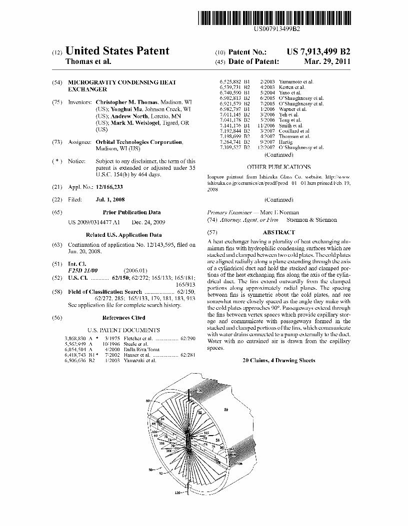
(57) ABSTRACT
A heat exchanger having a plurality of heat exchanging alu-minum fins with hydrophilic condensing surfaces which arestacked and clamped between two cold plates. The cold platesare aligned radially along a plane extending through the axisof a cylindrical duct and hold the stacked and clamped por-tions of the heat exchanging fins along the axis of the cylin-drical duct. The fins extend outwardly from the clampedportions along approximately radial planes. The spacingbetween fins is symmetric about the cold plates, and aresomewhat more closely spaced as the angle they make withthe cold plates approaches 90°. Passageways extend throughthe fins between vertex spaces which provide capillary stor-age and communicate with passageways formed in thestacked and clamped portions of the fins, which communicatewith water drains connected to a pump externally to the duct.Water with no entrained air is drawn from the capillaryspaces.
20 Claims, 4 Drawing Sheets

US 7,913,499 B2Page 2
U.S. PATENT DOCUMENTS7,326,656 B2 2/2008 Brask et al.
2007/0199677 Al * 8/2007 Hwang et al ................. 165/80.3
OTHER PUBLICATIONS
"Surface modification for hydrophilic property of stainless steeltreated by atmospheric-pressure plasma jet", by M.C. Kim, D.K.Song, H.S. Shin, S.H. Baeg, G.S. Kim, J.H. Boo J.G. Han, S.H.Yang,
Surface and Coatings Technology 171 (2003) pp. 312-316, © 2003Elsevier Science B.V."Results of Plasma-Generated Hydrophilic and Antimicrobial Sur-faces for Fluid Management Applications", by Yonghui Ma, ChrisThomas, Hongquan Jiang, Sorin Manolache, Mark Weislogel,Orbitech Technologies Corporation 2007-01-3139 copyright © 2007SAE International.
* cited by examiner
U.S. Patent Mar. 29, 2011 Sheet I of 4
US 7,913,499 B2
-OH -OH170
-OH OH -OH -OH _OH-OH -OH 3OHOH
- _OH-OH -OH _OH
Silicon _OH 3420--' n;,
2
Figol
/ 29
2s 36/
7426 24
10,OLtmo —-0,—
1200--
1000--_
0
o--
o-
nm
).Oum
U.S. Patent Mar. 29, 2011 Sheet 2 of 4 US 7,913,499 B2
Fig.2
U.S. Patent Mar. 29, 2011 Sheet 3 of 4 US 7,913,499 B2
a'0
U.S. Patent
Mar. 29, 2011 Sheet 4 of 4 US 7,913,499 B2
Cfl
.TWAcc
NN
_TT
t-I
00O 00 1
ell
-O
O ^ ^
tt^O
N
_ Nr-I
N
co I rN-IOI 00 cMN O O
NNr-I
US 7,913,499 B21
MICROGRAVITY CONDENSING HEATEXCHANGER
CROSS REFERENCES TO RELATEDAPPLICATIONS
This application is a continuation of U.S. application Ser.No. 12/143,595, filed Jun. 20, 2008, the disclosure of whichisincorporated herein by reference.
STATEMENT AS TO RIGHTS TO INVENTIONSMADE UNDER FEDERALLY SPONSORED
RESEARCH AND DEVELOPMENT
The U.S. Government has a paid-up license in this inven-tion and the right in limited circumstances to require thepatent owner to license others on reasonable terms as pro-vided for by the terms of Agreement No. NNJ05JE75Cawarded by NASA JSC.
JOINT RESEARCH AGREEMENT
Orbital Technologies Corporation, assignee of the subjectapplication, and Dr. Mark M. Weislogel, joint inventor of thesubject application, were parties to a j oint research agreementexecuted on Oct. 19, 2005. The agreement related to researchand development in the field of microgravity condensing heatexchangers.
BACKGROUND OF THE INVENTION
The present invention relates to heat exchangers in generaland heat exchangers for use in microgravity in particular andmore generally to hydrophilic antimicrobial coatings for usein heat exchangers.
Hydrophilic surfaces are those with the property of attract-ing water so that a drop of water on the hydrophilic surfacehas a relatively low angle of contact with the hydrophilicsurface. Contact angle is defined as a line tangent to the dropsurface where it attaches to a surface. If the contact angle isgreater than 90° the surface is said to be hydrophobic ornon-wettable, if the contact angle is less than 90° the surfaceis characterized as wettable and hydrophilic. The interactionbetween liquid water and a solid surface is related to thephenomenon of surface tension where the attraction of thewater molecules to each other draws the molecules of water atthe surface inwardly, creating a molecular film of water mol-ecules which acts like an elastic surface. Where the attractionbetween the liquid and the solid surface is greater than thesurface tension forces i.e., greater than the attraction betweenthe water molecules, water is drawn along the surface or intopores of the material according to a phenomenon known ascapillary action. Controlling the interaction of a liquid, par-ticularly water, with surfaces has many useful applications inaddition to heat exchangers, for example in printing, and inthe preventing of the formation of droplets on optical surfacesand windows.
A hydrophilic surface is advantageously used in a heatexchanger to cause water droplets which condense on the heatexchanger to spread out on the surface and flow towardscapillary channels where the water can be collected withoutdependence on gravity.
In any situation where water is handled, especially watercondensed from respired air, which necessarily is contami-nated with minute amounts of organic material, the formationof biofilms can be a problem. A biofilm is an aggregation ofmicroorganisms which excretes a protective and adhesive
2matrix, in the form of an extracellular matrix of polymericsubstances which strongly attaches to the surface on which itforms. Biofilms are especially a problem in heat exchangersbecause they can reduce the effectiveness of heat transfer
5 between the air and the cool surfaces of the heat exchangerand increase the pressure drop through the heat exchanger.Where the heat exchanger is used with air which is recircu-lated for breathing, the presence of biofilms poses a risk thatpathogens from the biofilm may contaminate the breathable
10 air.Condensing heat exchangers for use in microgravity such
as disclosed in U.S. Pat. No. 6,418,743 utilize coating form-ing hydrophilic surfaces with antimicrobial properties, suchcoatings assist in the transportation of water by capillary
15 forces in microgravity. However, problems can arise withprior art hydrophilic coatings due to detachment of the coat-ing from the condenser surfaces.
What is needed is a durable surface coating which can beapplied to a variety of substrates and which imparts hydro-
20 philicity to the surface while at the same time providingantimicrobial properties to control the growth of biofilms andpathogens. Further a condensing heat exchanger designwhich is adapted to be used with the improved hydrophilicand antimicrobial coating is needed.
25
SUMMARY OF THE INVENTION
The antimicrobial hydrophilic coating of this invention canbe applied to a variety of surfaces including anodized alumi-
3o num, passivated stainless steel, graphite, aluminum oxide,and certain plastic surfaces including polycarbonate resinsold under the trademark LEXANO, and amorphous poly-etherimide sold as ULTEM® (Lexan® and Ultem(k are reg-istered trademarks of SABIC Innovative Plastics). The anti-
35 microbial hydrophilic coating is applied over a passivesurface such as anodized aluminum which is thoroughlycleaned. A layer of titanium or chromium is formed on theanodized surface for better bonding and to limit corrosion. Onthe titanium or chromium a layer of silver of approximately
4o 400 nm thickness is formed. On top of the clean un-oxidizedsilver layer there is a layer of crosslinked, silicon-based mac-romolecular structure of approximately 10 nm thickness. Theoutermost surface of the layer of the silicon-based structure ishydroxide terminated to produce a hydrophilic surface with a
45 water drop contact angle of, for example, less than 10° or lessthan can be measured.
The method of constructing the coating on aluminuminvolves forming a sealed hard-coat anodizing, followed bycleaning and drying the anodized surface. The layer of tita-
5o nium is formed by sputtering onto the clean anodized surfaceof the aluminum. If chrome is used it may be electroplated.Silver is then sputtered onto the clean anodizing to a thicknessof approximately 400 mu. The silver surface is again cleanedand a 10 nm layer of silicon-based structure is deposited from
55 a plasma of silicon tetrachloride also known as tetrachlorosi-lane. The layer deposited from the tetrachlorosilane is thentreated with boiling water which produces the hydroxideterminations on the silicon-based structure surface whichimparts the hydrophilicity.
60 The hydrophilic antimicrobial coating of this inventionutilizes techniques, particularly with respect to the silversputtering, which are primarily line of sight deposition tech-niques and are therefore best used on flat fins, or fins withsimple geometries. A heat exchanger which employs the
65 hydrophilic antimicrobial coating of this invention utilizes aplurality of heat exchanging aluminum fins which are stackedand clamped between two cold plates. The cold plates are
US 7,913,499 B2
3aligned radially along a plane extending through the axis of acylindrical duct and hold the stacked and clamped portions ofthe heat exchanging fins along the axis of the cylindrical duct.The fins extend outwardly from the clamped portions alongapproximately radial planes. The spacing between fins issymmetric about the cold plates, and are somewhat moreclosely spaced as the angle they make with the cold platesapproaches 90°. Capillary spaces are created in the vertexesformed in between adjacent fins. The variation in anglesbetween the fins creates a capillary gradient that passivelypumps condensate from the cold plates toward the center finwhere it is pumped out of the fin assemblies. In additionwhere more narrow vertex angles are formed between adja-cent fins, more capillary storage is facilitated. Passagewayswhich are periodically spaced in the axial direction areformed through the fins to allow communication of the con-densed water between adjacent vertex spaces i.e., space thatprovide for capillary storage. Capillary spaces formed by thevertex angles are also in communication with passagewaysformed in the stacked and clamped portions of the fins, whichin turn communicate with water drains which extend exter-nally to the duct. Water with little or no entrained air can bedrawn from the capillary spaces with a simple low-volumeliquid pump.
Air from which moisture is to be removed is caused tomove by a fan through an air filter which removes particulatecontaminants. After the air filter the air moves through aprecooler which cools the air to a temperature whichapproaches the dew point, but which does not cause conden-sation to form. Because no condensation takes place in theprecooler there is no need for hydrophilic or antimicrobialproperties in the heat exchanger fins used in the precooler.The filtered and pre-cooled air is then caused to flow throughthe duct containing the condensing heat exchanger wherecooling fluid circulating through the opposed cold platesdraws heat from the heat exchanger fins causing their tem-perature to drop below the dew point of the air being dehu-midified. Because of the high hydrophilicity on fin surfaceswater condenses as a thin film which is constantly beingdrained to the capillary spaces and hence to the condensationdrains.
It is a feature of the present invention to provide a durablehydrophilic surface with antimicrobial properties.
It is a further feature of the present invention to provide amore durable surface for a microgravity condensing heatexchanger.
It is yet another feature of the present invention to providea coating which reduces the pressure drop through a condens-ing heat exchanger.
It is still another feature of the present invention to providea condensing heat exchanger from which condensate watercan be drawn with little or no entrained air.
It is still yet another feature of the present invention toprovide a method of forming antimicrobial hydrophilic sur-faces on a variety of substrate materials including bothorganic and inorganic materials.
Further objects, features and advantages of the inventionwill be apparent from the following detailed description whentaken in conjunction with the accompanying drawings.
BRIEF DESCRIPTION OF THE DRAWINGS
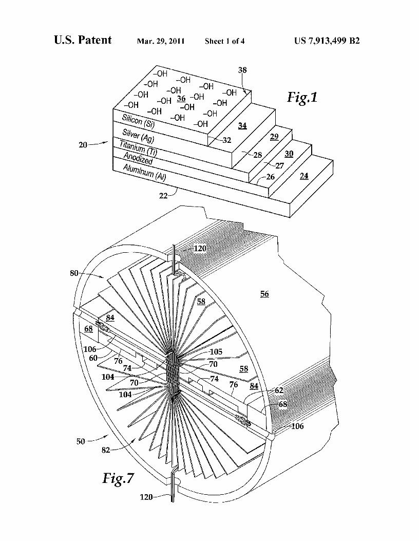
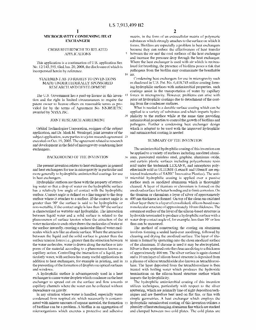
FIG.1 is an schematic view of the substrate coated with thehydrophilic antimicrobial coating of this invention.
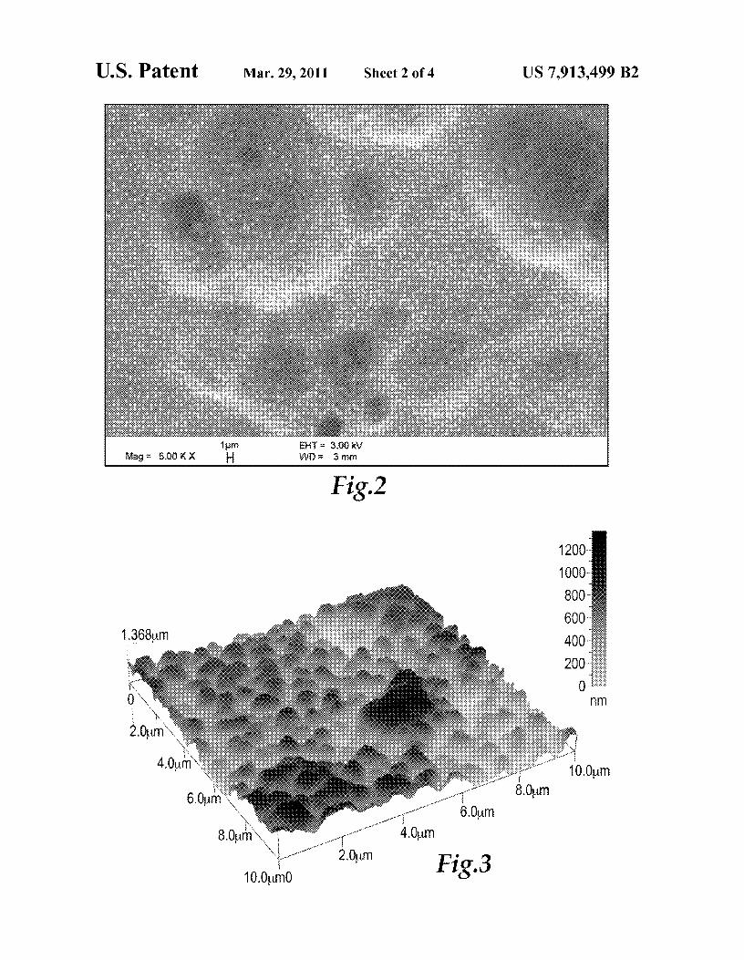
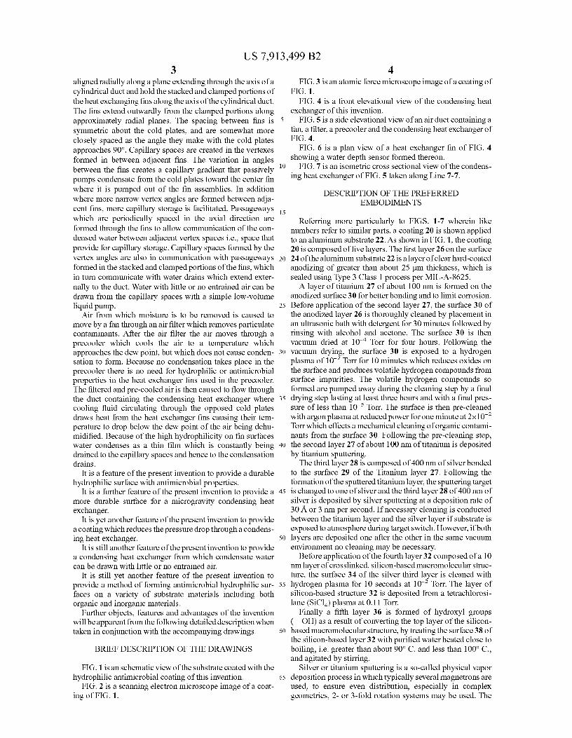
FIG. 2 is a scanning electron microscope image of a coat-ing of FIG. 1.
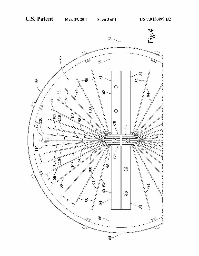
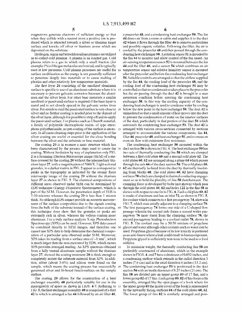
4FIG. 3 is an atomic force microscope image of a coating of
FIG. 1.FIG. 4 is a front elevational view of the condensing heat
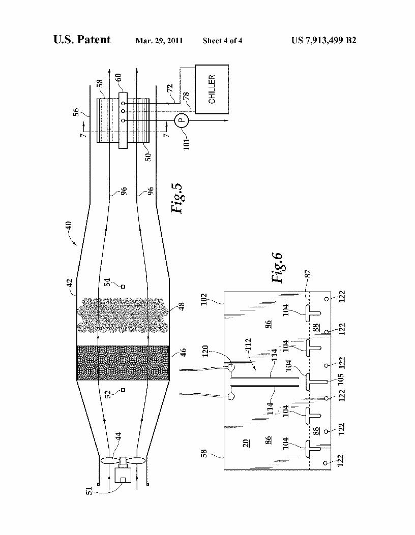
exchanger of this invention.5 FIG. 5 is a side elevational view of an air duct containing a
fan, a filter, a precooler and the condensing heat exchanger ofFIG. 4.
FIG. 6 is a plan view of a heat exchanger fin of FIG. 4showing a water depth sensor formed thereon.
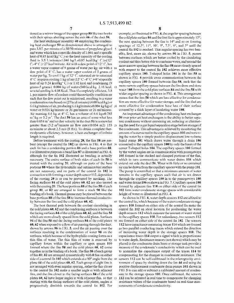
10 FIG. 7 is an isometric cross sectional view of the condens-ing heat exchanger of FIG. 5 taken along Line 7-7.
DESCRIPTION OF THE PREFERREDEMBODIMENTS
15
Referring more particularly to FIGS. 1-7 wherein likenumbers refer to similar parts, a coating 20 is shown appliedto an aluminum substrate 22. As shown in FIG. 1, the coating20 is composed of five layers. The first layer 26 on the surface
20 24 of the aluminum substrate 22 is a layer of clear hard-coatedanodizing of greater than about 25 µm thickness, which issealed using Type 3 Class 1 process per MIL-A-8625.
A layer of titanium 27 of about 100 run is formed on theanodized surface 30 for better bonding and to limit corrosion.
25 Before application of the second layer 27, the surface 30 ofthe anodized layer 26 is thoroughly cleaned by placement inan ultrasonic bath with detergent for 30 minutes followed byrinsing with alcohol and acetone. The surface 30 is thenvacuum dried at 10-4 Torr for four hours. Following the
30 vacuum drying, the surface 30 is exposed to a hydrogenplasma of 10-2 Torr for 10 minutes which reduces oxides onthe surface and produces volatile hydrogen compounds fromsurface impurities. The volatile hydrogen compounds soformed are pumped away during the cleaning step by a final
35 drying step lasting at least three hours and with a final pres-sure of less than 10-5 Torr. The surface is then pre-cleanedwith argon plasma at reduced power for one minute at 2 x 10 -2
Torr which effects a mechanical cleaning of organic contami-nants from the surface 30. Following the pre-cleaning step,
40 the second layer 27 of about 100 nm of titanium is depositedby titanium sputtering.
The third layer 28 is composed of 400 run of silver bondedto the surface 29 of the Titanium layer 27. Following theformation of the sputtered titanium layer, the sputtering target
45 is changed to one of sliver and the third layer 28 of 400 nm ofsilver is deposited by silver sputtering at a deposition rate of30 A or 3 run per second. If necessary cleaning is conductedbetween the titanium layer and the silver layer if substrate isexposed to atmosphere during target switch. However, if both
50 layers are deposited one after the other in the same vacuumenvironment no cleaning may be necessary.
Before application of the fourth layer 32 composed of a 10run layer of crosslinked, silicon-based macromolecular struc-ture, the surface 34 of the silver third layer is cleaned with
55 hydrogen plasma for 10 seconds at 10-2 Torr. The layer ofsilicon-based structure 32 is deposited from a tetrachlorosi-lane (SiC14) plasma at 0.11 Torr.
Finally a fifth layer 36 is formed of hydroxyl groups( OH) as a result of converting the top layer of the silicon-
6o based macromolecular structure, by treating the surface 38 ofthe silicon-based layer 32 with purified water heated close toboiling, i.e. greater than about 90° C. and less than 100° C.,and agitated by stirring.
Silver or titanium sputtering is a so-called physical vapor65 deposition process in which typically several magnetrons are
used, to ensure even distribution, especially in complexgeometries, 2- or 3-fold rotation systems may be used. The
US 7,913,499 B25
6magnetrons generate electrons of sufficient energy so that a precooler 48, and a condensing heat exchanger 50. The fanwhen they collide with a neutral atom a positive ion is pro- 44 draws air from a room or cabin and supplies it to the ductduced which is attracted towards a silver or titanium target
42 where it flows through the filter 46 to remove particulates
surface and knocks off silver or titanium atoms which are and possibly organic volatiles. Following the filter, the air isdeposited on the substrate. 5 cooled by the precooler 48 and then passed through the con-
Hydrogen, argon and tetrachlorosilane plasmas areutilized
densing heat exchanger 50. A rotation sensor 51 is mounted toas so-called cold plasmas. A plasma is an ionized gas. Cold
the fan 44 to monitor and allow control of the fan speed. An
plasma refers to a gas in which only a small fraction (for air-sensing temperature sensor 52 is mounted between the fanexample 1 %) of the gas molecules are ionized, and is typically
44 and the filter 46, and a sensor 54 which combines an air
used at low pressures. Cold plasma processes are useful for io temperature sensor and relative humidity sensor is mountedsurface modification as the energy is not generally sufficient after the precooler and before the condensing heat exchangerto penetrate deeply into materials or to cause melting of
50. Suitable controls are arranged so that the airflow supplied
plastics and other relatively low temperature materials. by the fan 44, the cooling load of the precooler 48, and theThe first layer 26 consisting of the anodized aluminum cooling load of the condensing heat exchanger 50 may be
surface is specific to use of an aluminum substrate where it is 15 controlled so thatno condensation takes place intheprecoolernecessary to prevent galvanic corrosion between the alumi- but the air passing through the duct 42 is brought to a nearnum and the silver layer. For other base materials a similar saturation condition before entering the condensing heatanodized or passivated surface is required if the base layer is exchanger 50. In this way the cooling capacity of the con-metal and is not closely spaced in the galvanic series from
densing heat exchanger is used to condense water by cooling
sliver. For stainless steel the passivated surface is very close to 20 below the dew point in the heat exchanger 50. The duct 42 issilver and no further coating is needed prior to the deposit of
uninsulated so that a small amount of heat moves into the duct
the silver layer, although it is possible to strip off and re-apply to prevent the condensation of water on the interior surfacesthe passivated surface. For plastics such as Ultem® material, of the duct, particularly in that portion of the duct 56 whicha family of polyimide thermoplastic resins, of type amor- surrounds the condensing heat exchanger 50. The duct 42 isphous polyetherimide, no pre-coating of the surface is neces- 25 arranged with various cross-sections connected by sectionssary. In all cases cleaning steps prior to the application of the arranged to accommodate the various components, fan 44,silver coating are useful or essential for the close bonding
filter 46, precooler 48, and heat exchanger 50, and to create an
between the silver and the substrate or base material. even air flow with minimum flow resistance.The coating 20 is in essence a nano structure which has
The condensing heat exchanger 50 mounted within the
been characterized by the process steps used to create the 3o duct section 56 is shown in FIG. 4. The heat exchanger 50 hascoating. Without limitation by way of explanation only FIG. two sets of thermally conducting fins 58 which are clamped2 is a Scanning Electron Microscope image (SEM) of a sur- between a first cold plate 60 and a second cold plate 62. Theface covered by the coating 20 without the intermediary tita- cold plates 60, 62 are arranged along a plane 64 which passesnium layer 27, with a magnification of 5000 X. Light-colored
through the axis 66 of the duct section 56. The cold plates 60,
granules, in a darker matrix in FIG. 2 appear to correspond to 35 62 are thermally isolated from the duct by thermally insulat-peaks in the topography as indicated by the atomic force
ing foam blocks 68. The cold plates 60, 62 have clamping
microscope image of the coating 20 without the titanium surfaces 70 which are clamped in thermal conducting engage-layer 27 as shown in FIG. 3. The chemical compositions of
ment so as to hold the plurality of fins 58 therebetween. The
different areas observed under SEM can be determined by clamping force is developed by bolts (not shown) which passEDS technique (Energy Dispersive Spectrometer), which is 40 through the cold plates 60, 62 and holes 122 in the fins 58 aspart of the SEM. However, the penetration depth of EDS is shown with respect to one fin in FIG. 6. Each cold plate 60, 625-10 microns whereas the coating 20 is less than 1 micron
is made of aluminum and has an inlet 72, as shown in FIG. 5,
thick. So although EDS cannot provide an accurate measure- for coolant which connects to a first passageway 74, shown inment of the surface composition due to the signals coming
FIG. 7, which runs axially adjacent to a clamping surface 70.
from the bulk of the substrate instead of the surface coating, 45 The first passageway 74 forms one side of a U-shaped flowthis technique does show that the granules or peaks are passage wherein the second side forms a second wider pas-extremely rich in silver, whereas the valleys contain more sageway 76 more distal from the clamping surface 70, thealuminum. For a truly surface analysis X-ray Photoelectron second passageway leading to a coolant outlet 78, shown inSpectroscopy (XPS) can be used. However, XPS data cannot
FIG. 5. The coolant may be a 50150 mixture of propylene
be correlated directly to SEM images, and therefore one 50 glycol and water although other coolants such as water can becannot use XPS data to help determine the chemical compo- used. Propylene glycol because of its low toxicity is preferredsition of a particular area observed under SEM. Moreover, as an anti-freeze where a leak could result in human exposure.XPS takes its reading from a surface area of —3 mm 2, which
Propylene glycol is sufficiently non-toxic to be used as a food
is much larger than the area measured by EDS, which means additive.XPS provides averaged reading. An XPS spectrum obtained 55 To minimize weight, the thermally conducting fins 58 arefrom a fully treated aluminum sample without the titanium preferably constructed of aluminum, which in the examplelayer 27, showed the coating treatment 20 is thick enough to shown in FIGS. 4, and 7 have a thickness of 0.032 inches, andcompletely isolate the substrate material from XPS. In addi- a condensing surface which extends in the radial direction 3tion, silver (about 3-6%) and silicon were found on the
inches (7.6 cm) and in the axial direction 6 inches (15.2 cm).
sample, which means the coating process has successfully 6o The condensing heat exchanger 50 is positioned in the ductgenerated silver and Si-based functionalities on the sample section 56 with an inside diameter of 8.25 inches (21 cm). Thesurface. fins 58 are divided into an upper group 80 of 17 fins, and a
The coating 20 allows for the construction of a heat
lower group 82 of 17 fins. Each group 80,82 of fins forms a finexchanger assembly 40 particularly suitable for use in the assembly, arranged like the open pages of a book where formicrogravity of space as shown in FIGS. 4-7. Referring to 65 the upper group 80 the inside cover of the book is representedFIG. 5, theheat exchanger assembly 40 is comprised of a duct
by the upwardly facing surfaces 84 of the cold plates 60, 62.
42 in which is arranged a fan 44 followed by an air filter 46, The lower group of fins 82 is similarly arranged and posi-
US 7,913,499 B27
tioned as a mirror image of the upper group 80 like two bookswith their spines abutting across the axis 66 of the duct 56.
The heat exchanger assembly 40 employing the condens-ing heat exchanger 50 as dimensioned above is arranged topass 3.8 L per minute of a 50150 mixture of propylene glycol 5
and water which has a specific density of 1.046 and a specificheat of 0.85 kcal/(kg' C.) so the heat capacity of the coolingfluid is 3.8 L/minutexl.046 kg/Lx0.85 kcal/(kg' C.)x(12°C.-4° C.)=27 kcal/minute. Air with a dew point of 12° C. hasa water vapor content of 9 grams of water per kg; air with a iodew point of 4° C. has a water vapor content of 5 grams ofwater per kg. To cool 1 kg of 12° C. saturated air to saturated4° C. requires cooling 1 kg of air (12° C.-4° C.)=8°x(specificheat of air 0.24 kcal/kg' C.) or 1.92 kcal and condensing (9grams-5 grams)-0.004 kg of waterx540 kcal/kg=2.16 kcal, 15
so total cooling is 4.08 Kcal. Thus if completely efficient, 3.8L per minute flow of coolant could theoretically condition airsuch that the dew point out is minimized, resulting in a watercondensation rate based on (27 kcal/minute)/(4.08 kcal/kg) or6.6 kg/minute of air, producing 6.6 kg/minutex0.004 kg/kg of 20
water or 0.026 kg/minute or 26 gm/minute or 26 ml/minute.Air massing 6.6 kg at 4° C. has a volume of 6.6 kgx0.785M3 /kg or 5.2 m3 . The duct 56 has an area of some what lessthan 0.034 m2 and so that velocity in the duct 56 is somewhatgreater than (5.2 M3 /minute air flow rate)/(0.034 m2)=153 25
m/minute or about 2.5 m/s (8 ft/s). To obtain complete ther-modynamic efficiency, however, a heat exchanger of infinitelength is required.
Before treatment with the coating 20, the fins 58 are pre-bent (except the central fin 102) as shown in FIG. 4 so that 30
each fin has a condensing portion 86 and a base portion 88.For illustrative purposes a bend line 87 is illustrated in FIG. 6,although for the fin 102 illustrated no bending is actuallynecessary. The entire surface of both sides of each fin 58 istreated with the coating 20, although on parts of the base 35
portions 88 where the hydrophilic and antimicrobial surfaceare not necessary, and on parts of the central fin 102 inconnection with forming a water depth sensor 112, depositionof the coating 20 is or can be prevented by masking. Thefacing surfaces 84 of the cold plates 60, 62 are also treated 40
with the coating 20. The base portions 88 of the fins 58 of eachgroup 80, or 82 are arranged to form a stack 90 like thebinding of a book. Thermal grease maybe placed between thebase portions 88 of the fins 58 to increase thermal conductiv-ity between the fins and the cold plates 60, 62. 45
The best thermal path between the coolant circulating inthe cold plates 60, 62 and the condensing surfaces is betweenthe facing surfaces 84 of the cold plates 60, 62, and the fins 58which are more closely spaced from the cold plates. Surfaces94 of the fins 58 and the facing surfaces 84 of the cold plates 50
60, 62 when exposed to a flow of air passing through the duct,shown by arrows 96 in FIG. 5, cool the air passing over thesurfaces resulting in the condensation of water 98 on thesurfaces, which because of the hydrophilic coating forms as athin film of water. The thin film of water is removed by 55
capillary forces within the capillary or apex spaces 100formed where the fins 58 and the cold plates 60, 62 cometogether as in the binding of a book. The fins 58 of each groupof fins 80, 82 are arranged symmetrically with 8 fins on eitherside of a central fin 102 which extends at a 90° angle from the 60
plane 64 of the cold plates 60, 62. Each group of eight fins isnot arranged with even angular spacing, rather the fins closerto the central fin 102 make a smaller angle a with adjacentfins, and the fins closer to the facing surfaces 84 of the coldplates 60, 62 have larger angles a with adjacent fins, so that 65
starting with the facing surfaces of the cold plates, angles aprogressively diminish towards the central fin 102. For
8example, as illustrated in FIG. 4, the angular spacing betweenthe cold plate surface 84 and the first fin is approximately 15',the next spacing between the fins is 14° and so on formingspacings of 12.5°, 11°, 10°, 9°, 7.5 0, 60, and 5 0 until thecentral fin 102 is reached. This angular spacing has two ben-efits, first, more air, shown by arrows 96 in FIG. 5, passesbetween surfaces which are better cooled by the circulatingcoolant and thus better able to condense water, and second themore narrow spacing between the fins 58 more closely spacedwith respect to the central fin 102 achieves more effectivecapillary spaces 100. T-shaped holes 104 in the fins 58 asshown in FIG. 6 provide cross communication between thecapillary spaces 100 formed between fins 58, such that themore narrow capillary spaces between the fins draw and storewater 108 from the cold plate surfaces 84 and the fins 58 withwider angular spacing as shown in FIG. 4. This arrangementmeans that the fins 58 which are less effective for condensa-tion are more effective for water storage, and the fins that aremore effective for condensation have less of their surfacecovered by a thick layer of insulating water 108.
An important advantage of the condensing heat exchanger50 over prior art heat exchangers is the ability to better sepa-rate condensate without entraining air, reducing or eliminat-ing the need for a gas liquid separation stage before storage ofthe condensate. This advantage is achieved by monitoring theamount of water stored in the capillary spaces 100 and remov-ing the water by a simple positive displacement low-volumeliquid pump 101 which draws water through a drain 106connected to the capillary spaces 100 by only the bases of thecenter T-shaped holes 104. The capillary spaces 100 formedby the vertex angles are in communication with passageways105 formed in the stacked and clamped portions of the fins,which in turn communicate with water drains 106 whichextend out side the duct 56. Water with little or no entrainedair can be drawn from the capillary spaces with the pump 101.The pump is controlled so that a minimum amount of waterremains in the capillary spaces such that air is not drawnthrough the capillary spaces 100 in to the passageways 105and water drains 106 as shown in FIG. 7. Capillary spaces 108formed by adjacent fins 110 on either side of the central fin102 form water condensate storage spaces with considerableheight of water as illustrated in FIG. 4.
As shown in FIG. 6, water depth sensors 112 are affixed tothe central fin, which because of the water condensate storagespaces 108 formed on either side of the central fin make thecentral fin 102 an ideal location for positioning the waterdepth sensors 112 which measure the amount of water storedin the capillary spaces 108. For redundancy, two sensors 112are formed on either side of the central fin 102. The sensors112 have capacitance measuring traces 114 which are formedas two parallel conducting traces which extend the directionof increasing water depth in the storage spaces 108. Thecapacitance traces 114 output a signal which is proportionateto water depth. Resistance sensors (not shown) which may beplaced in the condensate drain lines or storage tank provide ameasure of the condensate's conductivity which can be usedto normalize the capacitance output of the traces 114 bycompensating for the changes in condensate resistance. Thesensors 112 can be self-calibrated in the microgravity envi-ronment of space by shutting down the fan 44 and using thepositive displacement condensate drain pumps 101 shown inFIG. 5 to can add or subtract a calibrated amount of conden-sate to the storage spaces 100. Once calibrated, the sensors112 can be adjusted in real time to compensate for changingresistance values of the condensate based on real-time mea-surements of condensate conductivity.
US 7,913,499 B29
The sensors 112 are formed on the surfaces 118 on eitherside of the central fin 102 such that the sensors do not interferewith the capillary storage of water. The design is compatiblewith the surface treatment process 20 and the water storagebehavior of the fin assemblies 80, 82. Silver is utilized for theelectrode material to enhance microbial control near the sen-sor. Silver traces are formed over the anodized layer 26 withsilver traces leading to an outer edge of the central fin 102where the sensor traces are connected to sensor connectors120, as shown in FIG. 4. In the fabrication of the central fin102 the silver layer 28 is not applied in an area about thesensor traces 114, by masking this area during silver deposi-tion to prevent shorting the traces, however the final layer ofsilicon-based structure 32 which forms the hydrophilic layer36 can be deposited over the silver leads in the insulatingspaces for uniform hydrophilicity of the fin surfaces 118 andthe sensor 112. No polymers or other foreign materials shouldbe added to the fin surfaces as they might reduce the quality ofthe surface coating 20. The sensor 112 and the traces 114 donot result in edges which act as pinning points for water. Suchpinning points would be detrimental to the water level mea-surements, because the measurement would not be universalto the entire fin assemblies 80, 82.
To initiate operation of the heat exchanger 40, the pump101 is operated in reverse to supply water to the capillaryspaces 100 of the condensing heat exchanger 50. Followingpriming in this way the fan 44, the pre-cooler 48 and thecondensing heat exchanger 50 are turned on and water iscondensed on fins 58. As condensate is built up in the capil-lary spaces 100 as indicated by the sensor 112, condensate iswithdrawn by the pump 101 in a controlled manner based onthe output of the sensor to prevent aspirating air with thedraining condensate.
It should be understood with the aluminum substrate 22 thelayer of sputtered titanium may not be present, or a layer ofelectroplated or otherwise deposited chromium may be usedbetween the anodized layer 30 and the silver layer 28. Anickel layer could also be used, for example electroless nickelof about 1200-1900 nm can be used between the anodizedlayer 30 and the silver layer 28. The titanium, chromium ornickel layer may be applied directly on an aluminum oxidelayer or on unoxidized aluminum. Chromium and nickel havethe advantage that they can be plated as opposed to therequired sputtering of titanium. The silver layer can also beelectroplated or chemically plated on the underlying sub-strate. In the case of electroplating or chemically plating thelayers will in general be thicker, for example when platingsliver over nickel a target silver plated layer of 400 nm mayhave an actual thickness ranging from about 400 nm to 1000mu. In some cases an electroplated or chemically plated layercan be even two to three orders of magnitude thicker thansputtered layers.
It should be understood that vacuum is generally under-stood herein as a pressure ranging from less than standardatmospheric pressure to as close as theoretically possible tothe complete absence of gas. The term is usefully divided upinto ranges with a medium vacuum constituting a pressure of25 to 1 x 10⁻³ Torr, and a high vacuum constituting a pressureof 1 x10⁻³ to 1 x10⁻⁹ Torr, such that the drying steps used toform the coating 20 are performed at high vacuum, whereasthe plasma treatment steps and the sputtering step are per-formed at medium vacuum.
It should be understood that the layer deposited from thetetrachlorosilane (SiC14) plasma is a layer of crosslinked,silicon-based macromolecular structure, which is also
10referred to herein as a layer of silicon-based structure. Thisterm serves to preserve the full breadth of the nano-structuredisclosed.
It is understood that the invention is not limited to the5 particular construction and arrangement of parts herein illus-
trated and described, but embraces all such modified formsthereof as come within the scope of the following claims.
We claim:1. A heat exchanger comprising:
10 a duct defining an air passage volume;at least one cold plate mounted within the duct and con-
nected to a source of circulation cooling fluid;a first plurality of water condensing elements clamped in
thermal conducting engagement with the at least one15 cold plate;
wherein each of the water condensing elements has a baseportion which is clamped directly to the at least one coldplate or to an adjacent base of one of said plurality ofwater condensing elements;
20 wherein each of the water condensing elements has a con-densing portion having two opposed water condensinghydrophilic surfaces which extend into the air passagevolume away from the cold plate;
wherein the plurality of water condensing elements with25 clamped bases define a stack of base portions and an
array of the condensing portions of the plurality of watercondensing elements which extend into the air passagevolume away from the cold plate;
wherein the plurality of condensing portion are angularly30 spaced with respect to each other and the least one cold
plate;wherein each water condensing portion of each water con-
densing element, together with either of the at least onecold plate or an adjacent condensing portion of one of
35 said plurality of water condensing elements defines acapillary space where said water condensing elementsengage either the cold plate or said adjacent one of saidplurality of water condensing elements, the plurality ofwater condensing elements and the at least one cold plate
40 thus defining a plurality of capillary spaces;wherein each capillary space of the plurality of capillary
spaces is in condensate communicating relation withevery other capillary space of first plurality of watercondensing elements;
45 a condensate drain in communication with said plurality ofcapillary spaces; and
a pump connected to draw water from said plurality ofcapillary spaces.
2. The heat exchanger of claim 1 wherein portions of each50 of the first plurality of water condensing elements define at
least one opening which provides the condensate drain com-municating between the plurality of capillary spaces andbetween the two opposed water condensing hydrophilic sur-faces.
55 3. The heat exchanger of claim 1 wherein portions of thewater condensing elements bases form at least part of thecondensate drain.
4. The heat exchanger of claim 1 wherein the angularspacing between the water condensing elements which
60 extend away from the stack is not uniform, such that somecapillary spaces draw water from other capillary spaces.
5. The heat exchanger of claim 1 further comprising acapacitive sensor comprising at least two conductive tracesformed on one of the two opposed water condensing hydro-
65 philic surfaces of a selected one of said plurality of watercondensing elements, which at least two conductive tracesextend in the radial direction with respect to said selected one
US 7,913,499 B211
of said plurality of water condensing elements, the sensorarranged to measure a height in the radial direction of con-densate collecting in one of the plurality of capillary spaces.
6. The heat exchanger of claim 1 wherein the at least onecold plate comprises:
• first cold plate; and• second cold plate, wherein the stack of base portions is
clamped between the first cold plate and the second coldplate.
7. The heat exchanger of claim 6 wherein the first pluralityof water condensing elements all extend upwardly, and fur-ther comprising:
a second plurality of water condensing elements clampedin thermal conducting engagement between the first coldplate and the second cold plate;
wherein each of the second water condensing elements hasa base portion which is clamped between the first coldplate and the second cold plate, wherein the clampedbase portions define a stack; and
wherein the second plurality of water condensing elementsall extend downwardly.
8. The heat exchanger of claim 7 wherein the first pluralityof water condensing elements are arranged like a first book,where the water condensing elements are open pages, andwhere the stack is a first book binding clamped between thefirst cold plate and the second cold plate, and
wherein the second plurality of water condensing elementsis arranged like a second book where the water condens-ing elements are open pages, and the stack is a secondbook binding clamped between the first cold plate andthe second cold plate so that the first book binding, andthe second book binding are arranged back to back andthe first book and the second book are arranged as sub-stantially mirror images.
9. The heat exchanger of claim 8 wherein the first pluralityof water condensing elements comprise an odd number ofwater condensing elements with an even number of said watercondensing elements on either side of the central water con-densing element.
10. The heat exchanger of claim 9 wherein the number ofthe first plurality of water condensing elements is 17, with 8water condensing elements on either side of the central watercondensing element and the angular spacing between adja-cent condensing portions of said water condensing elementsis approximately 14°, 12.5°, 11°, 10°, 9°, 7.5°, 6°, and 5° asthe central water condensing element is approached, so thatthe condensing portions of the water condensing elements aresymmetrically arranged on either side of the central watercondensing element and are more closely angularly space asthe central water condensing element is approached.
11. The heat exchanger of claim 1 wherein each of the firstplurality of water condensing elements, is made of aluminum.
12. A microgravity condensing heat exchanger compris-ing;
• duct defining a flow passage for air, and defining anairflow direction;
• cold plate connected to source of cooling liquid, mountedto the duct;
an array of aluminum condensing elements, arranged likeopen pages of a book, wherein the aluminum condensingelements form a stack like a binding of the book, thestack clamped in thermal conductive relation to the coldplate;
each aluminum condensing elements of the array havingwater condensing portions which extend in a radialdirection from the binding like the page of the openbook, the water condensing portions are angularly
12spaced from each other and define capillary spaceswhere the aluminum condensing elements meet at thestack, like the pages and meet in the binding of the book,the water condensing portion extending into the flow
5 passage defined by the duct, and parallel to the airflowdirection;
portions of the aluminum condensing elements formingcommunication openings between the capillary spaces;and
10 a condensate drain connected between at least one of thecapillary spaces, and a condensate pump to communi-cate condensate between the at least one of the capillaryspaces and the condensate pump.
15 13. The microgravity condensing heat exchanger of claim12 wherein some of the aluminum condensing elements aremore closely angularly spaced than other aluminum condens-ing elements in the array of aluminum condensing elements,and wherein the condensate drain is in communication with a
20 capillary space formed between said more closely angularlyspaced aluminum condensing elements.
14. The microgravity condensing heat exchanger of claim13 further comprising a capacitive sensor comprising at leasttwo conductive traces formed on a surface of one of the
25 aluminum condensing elements which are more closelyangularly spaced, which at least two conductive traces extendin the radial direction with respect to one of said of thealuminum condensing elements, the sensor arranged to mea-sure a condensate height in the radial direction of condensate
30 collecting in one of the plurality of capillary spaces.15. A process for condensing condensate from circulating
gas in a cabin or room in microgravity comprising the stepsof:
circulating gases containing condensate vapor through a35 duct;
within the duct pre-cooling by passing the gases through aprecooler to cool the gases to a temperature approachingbut not less than a dew point defined by the condensatevapor contained in the circulating gases;
40 passing the pre-cooled gases parallel to and between aplurality of planer condensing elements which areactively cooled below the dew point, said plurality ofplaner condensing elements forming a condensing heatexchanger;
45 condensing the condensate on hydrophilic surfaces formedon the condensing elements;
collecting condensate in capillary spaces formed wheretheplurality of planer condensing elements are broughttogether forming apexes therebetween;
50 communicating the collected condensate between the cap-illary spaces through openings formed in the planer con-densing elements to define interconnected capillaryspaces;
measuring collected condensate between two of the plural-55 ity of planar condensing elements to determine a height
of the condensate therebetween; andoperating a pump to drain condensate from the intercon-
nected capillary spaces when the measured condensateheight is sufficient to prevent the gases from being
60 entrained with the condensate.16. The process of claim 15 further comprising the step of
operating the pump in reverse to purge gases from and supplya condensate to the capillary spaces until the measured con-densate height is sufficient to prevent the gases from being
65 entrained with the condensate before condensing the conden-sate on the hydrophilic surfaces formed on the condensingelements.
US 7,913,499 B213
17. The process of claim 15 further comprising the step ofmeasuring the temperature of the gases before they passthrough the precooler, and measuring the temperature andrelative humidity of the gases after they pass from the pre-cooler, and controlling the flow of gases, or the cooling effectof the precooler so that the gases are cooled to a temperatureapproaching but not exceeding the dew point defined by thecondensate vapor contained in the circulating gases.
18. A microgravity condensing heat exchanger compris-ing;
a duct defining a flow passage for air flowing in an airflowdirection;
a cold plate connected to a source of cooling liquid, thecold plate being mounted within the duct;
a first condensing element, a second condensing element,and a third condensing element, each having a baseportion and a water condensing portion extending fromthe base portion, and each condensing element furtherhaving two opposed hydrophillic surfaces, and portionsof each condensing element define a communicationopening which extends between the two opposed hydro-phillic surfaces;
wherein the second condensing element base portion isclamped between the first condensing element base por-tion and the third condensing element base portion, andthe clamped base portions of the first condensing ele-ment, second condensing element and third condensingelement are engaged in thermally conducting relation-ship with the cold plate;
wherein the water condensing portion of the first condens-ing element and the water condensing portion of thethird condensing element extend in diverging relation-
14ship from the water condensing portion of the secondcondensing element to define a first capillary spacebetween the first condensing element and the secondcondensing element, and a second capillary space
5 between the second condensing element and the thirdcondensing element, the water condensing portionsextending into the duct flow passage parallel to the air-flow direction, wherein the condensing element commu-nication openings communicate with the first capillary
10 space and the second capillary space; anda condensate drain connected in condensate receiving rela-
tion to at least one of the first capillary space and thesecond capillary space, the condensate drain being con-nected to a condensate pump.
15 19. The heat exchanger of claim 18 wherein the watercondensing portion of the first condensing element extends ata first angle from the water condensing portion of the secondcondensing element, and the water condensing portion of thethird condensing element extends at a second angle from the
20 water condensing portion of the second condensing element,and wherein the first angle is less than the second angle, suchthat the first capillary space draws water from the secondcapillary space.
20. The heat exchanger of claim 18 further comprising a25 capacitive sensor comprising at least two conductive traces
formed on one of the two opposed water condensing hydro-philic surfaces of the second condensing element, so that theconductive traces extending in a radial direction into and outof first capillary space, the sensor arranged to measure a
so height in the radial direction of condensate collecting in thefirst capillary space.