Embed Size (px)
Citation preview

United States Patent (19) 11 Patent Number: 5,041,834 Koert (45) Date of Patent: Aug. 20, 1991 y
(54) ARTIFICIAL IONOSPHERIC MIRROR 4,253,190 2/1981 Csonka .................................. 455/12 COMPOSED OF A PLASMA LAYER WHICH 4,686,605 8/1987 Eastlund ............................. 361/231 CAN BE TILTED 4,712,155 12/1987 Eastlund et al. .................... 361/23
4,817,495 4/1989 Drobot ................................. 89/. 75 : Yas (75) Inventor: Peter Koert, Washington, D.C Primary Examiner-Gregory C. Issing 73) Assignee: APTI, Inc., Washington, D.C. Attorney, Agent, or Firm-Foley & Lardner (21) Appl. No.: 524,435 57 ABSTRACT 22 Filed: May 17, 1990 This invention relates to generation of a Artificial Iono
spheric Mirror (AIM), or a plasma layer in the atmo 51) Int. C.’.......................... H04B 7/00; HO1Q 3/22 sphere. The AIM is used like the ionosphere to reflect (52) U.S. Cl. ..................................... 342/367; 342/372 RF energy over great distances. A tiltable AIM is cre 58 Field of Search ............... 342/367, 353, 371, 372; ated by a heater antenna controlled in phase and fre
455/64 quency. The heater antenna phase shift scans a beam to (56) References Cited paint a. plasma layer. Frequency is changed to refocus at
U.S. PATENT DOCUMENTS continually higher altitudes to tilt the plasma layer.
3,445,844 5/1969 Grossi et al. ........................ 342/367 16 Claims, 15 Drawing Sheets

U.S. Patent Aug. 20, 1991 Sheet 1 of 15 5,041,834
Sheet 2 of 15 5,041,834 Aug. 20, 1991 U.S. Patent
U.S. Patent Aug. 20, 1991 Sheet 3 of 15 5,041,834
Focus Point
Element (i,j)

U.S. Patent Aug. 20, 1991 Sheet 4 of 15 5,041,834
Upper Bound of power ochievoble - up unas apa as a Power of heater ontenno focused
Ot 6O Km
O 2O 4O 6O 8O OO 2O 4 O 6O
Altitude z in Km
FG.4
U.S. Patent Aug. 20, 1991 Sheet 5 of 15 5,041,834
FG.5

U.S. Patent Aug. 20, 1991 Sheet 6 of 15 5,041,834

Sheet 7 of 15 5,041,834 Aug. 20, 1991 U.S. Patent
FIG.8
U.S. Patent Aug. 20, 1991 Sheet 8 of 15 5,041,834
O
-5
CD
-IO C O
.
-15 Element if 5 Element if IO
-2O Element 42O
O OO 20O 3OO 4OO 5OO 6OO 7OO 8OO 900 OOO
Distonce in meters
Phose Corrections to move focal point from 6OKm to 6|Km
FG.9

U.S. Patent Aug. 20, 1991 Sheet 9 of 15 5,041,834
O
O O OO 200 3OO 4OO 5OO 6OO 7OO 8OO 900 IOOO
Distance in meters Frequency Correction to move focal point from 6OKm to 6|Km
FG.O

U.S. Patent Aug. 20, 1991 Sheet 10 of 15 5,041,834
76.O Plasma layer location
without frequency chirping 75.2 to Olter Otitude
fe Se op 74.4 o 2
736
72.8
72.O -O7 -O.4 -O. O. O.4 O.7
Horizontal DistOnce (Km)
Heater focusing at 75Km with 550 MHz frequency and 54 dBW
FG.

U.S. Patent Aug. 20, 1991 Sheet 11 of 15 5,041,834
76.O Plasma layer location with frequency chirping to Oter Oltitude
7 5. 2
74. 4.
73.6
72.8
72.O -O.7 -O.4 - O. O. O.4 O.7
Horizontal Distance (Km)
Heater Focusing at 75Km with 55O to 559,375 MHz frequency and 154 dBW
FG.2

5,041,834 U.S. Patent
Sheet 13 of 15 5,041,834 Aug. 20, 1991 U.S. Patent
gO]
esind ue?De? ? oasri g?TI
Electron Density (cm) 901
U.S. Patent Aug. 20, 1991 Sheet 14 of 15 5,041,834
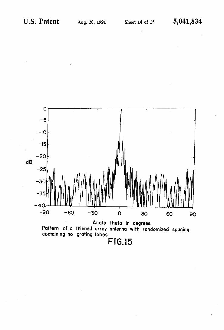
Angle the to in degrees Pattern of a thinned array antenna with randomized Spacing Containing no grating lobes
FIG.5
U.S. Patent Aug. 20, 1991 Sheet 15 of 15 5,041,834

5,041,834 1.
ARTIFICIAL ONOSPHERIC MERROR COMPOSED OF A PLASMA LAYER WHICH CAN
BETILTED
BACKGROUND OF THE INVENTION
1. Field of the Invention This invention relates to generation of a Artificial
Ionospheric Mirror (AIM), or a plasma layer in the atmosphere. The AIM is used like the ionosphere to reflect RF energy over great distances.
2. Description of the Related Art In the past, the technique of using the ionosphere as a
mirror to reflect radio waves, or RF energy, has given Han Radio operators the ability to send transmissions over long distances. This technique has also provided radar systems the ability to look "over the horizon.' Variations and fluctuations in the ionosphere, however, can render the effectiveness of such communications uncertain. Thus, the desirability of creating controllable plasma layers in the atmosphere for communications purposes has been recognized. See, for example, U.S. Pat. No. 4,686,605 issued to Eastlund and U.S. Pat. No. 4,72,155 issued to Eastlund et al.
Previous experiments directed toward creating plasma layers for communications have suffered from the inability to control the inclination of the plasma layer so that signals could be transmitted and received from various ranges. In other words, while one could create a plasma layer in the atmosphere at a lower alti tude than the ionosphere, point to point communica tions would be limited in range based on the reflection angles of the transmitted and reflected signals.
SUMMARY AND OBJECTS OF THE INVENTION
In view of the limitations of the related art it is an object of this invention to generate a plasma layer that could be angled or tilted with respect to the horizon in order to affect signal transmission range. The present invention provides a system and method
for generating a plasma layer at controlled altitudes and inclinations that acts as an artificial ionospheric mirror (AIM) to reflect RF signals. The AIM increases the range and predictability with which RF energy may be reflected off the AIM for communications purposes. More specifically, a tiltable AIM is created by a heater antenna controlled in phase and frequency. The heater antenna phase shift scans a beam to paint a plasma layer. The heater antenna continually refocuses at a higher altitudes by frequency shifting to tilt the plasma layer. BRIEF DESCRIPTION OF THE DRAWINGS
Further details of the present invention are explained with the help of the attached drawings in which: FIG. 1 shows creation of an AIM by a heater antenna
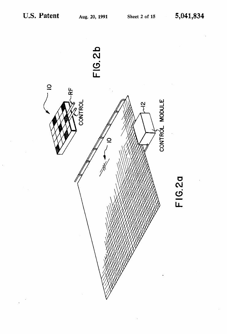
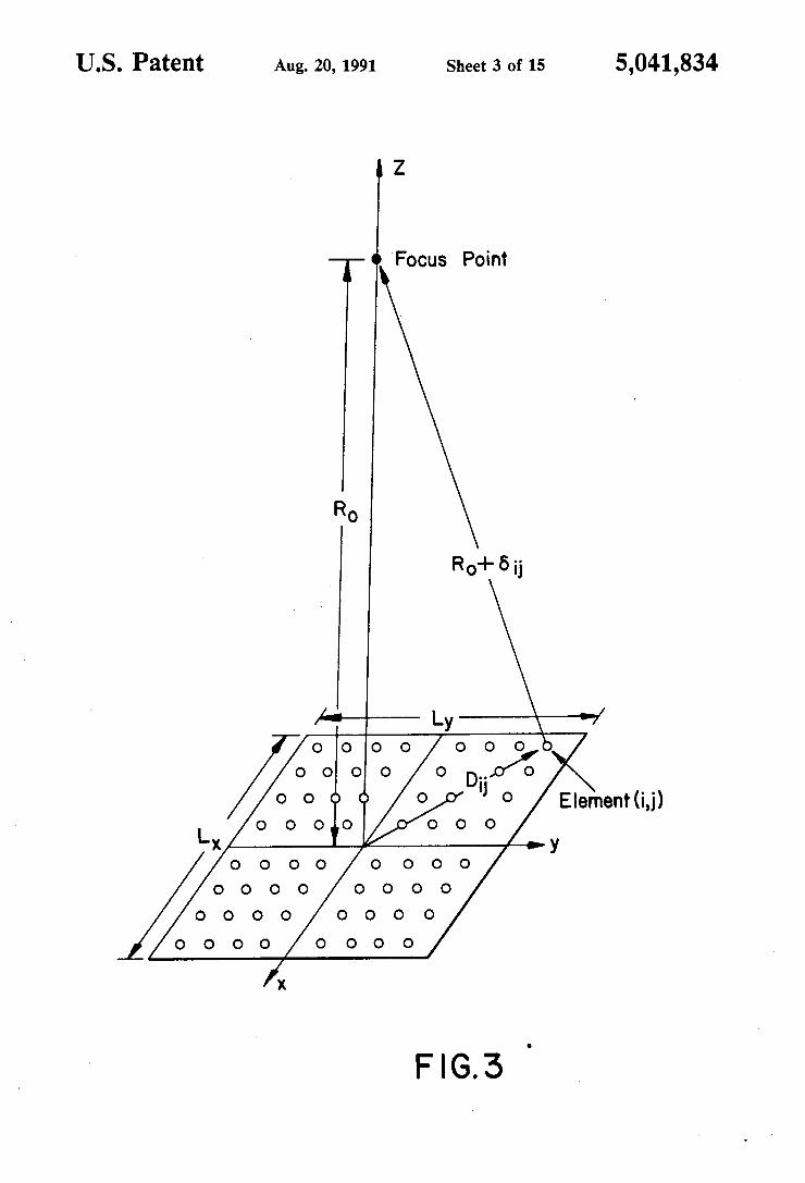
and use of the AIM for tracking aircraft and reflecting radio waves. FIG. 2 shows a typical heater array. FIG. 3 shows the spacial relationship for a heater
array used in defining heater array focusing. FIG. 4 is a graph showing that power is at its upper
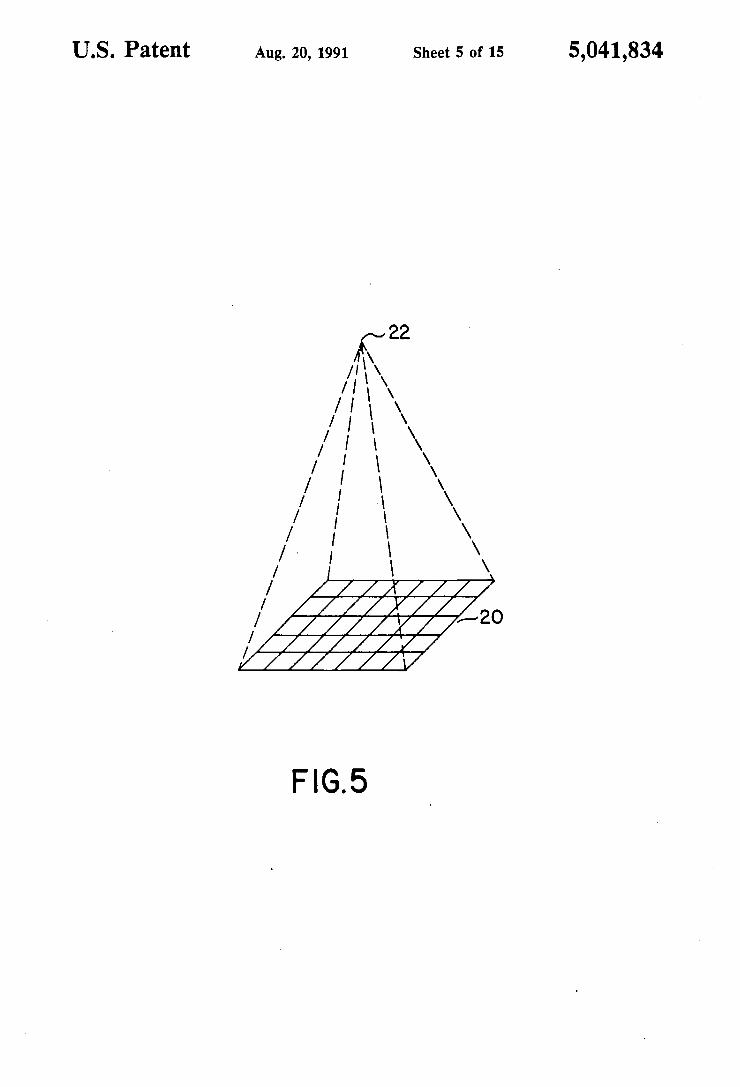
bound at the antenna focal point. FIG. 5 shows generation of plasma by a heater array. FIG. 6 illustrates generation of a plasma layer by
scanning a heater antenna.
15
2 FIG. 7 illustrates generation of a tilted plasma layer
by scanning and refocusing a heater antenna. FIG. 8 shows generation of a plasma layer using a
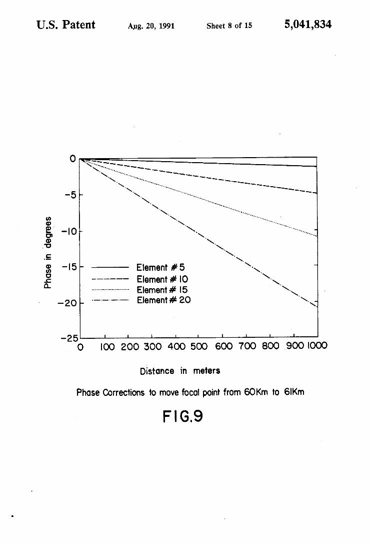
heater antenna to scan with a line rather than a point. FIG. 9 shows the phase corrections to move the
antenna focal point from 60 Km to 61 Km. FIG. 10 shows the frequency corrections to move the
antenna focal point from 60 Km to 61 Km. FIG. 11 is a plot of altitude v. distance location of
plasma without frequency chirping. FIG, 12 is a plot of altitude v. distance location of
plasma with frequency chirping. FIG. 13 shows the power density change after refo
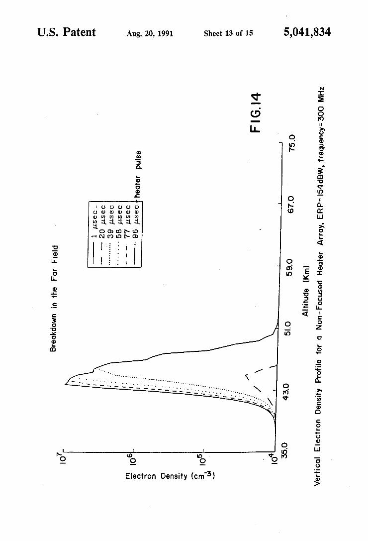
cusing using frequency chirping. FIG. 14 graphs the free electron density v. altitude
for an unfocused array.
25
30
35
45
50
55
65
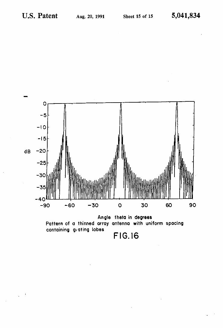
FIG. 15 shows an antenna power pattern without grating lobes. FIG. 16 shows an antenna power pattern with grating
lobes.
DETAILED DESCRIPTION OF THE PREFERRED EMBODIMENTS
FIG. 1 illustrates the creation and use of An Artificial Ionospheric Mirror (AIM) for tracking aircraft and reflecting radio waves. A heater antenna 1 radiates power causing avalanche ionization or breakdown re leasing free electrons in the atmosphere to generate the AIM 2. The heater antenna 1 is an array which can be used to focus energy at varying altitudes and elevations to tilt the AIM 2 using phase and frequency control. The AIM 2 simulates the ionosphere 3 which is also used to detect "over the horizon targets' 5. In addition, the AIM 2 can reflect radio signals transmitted from a transmitter 6 to a receiver 7 over long distances. A typical heater antenna is shown in FIG. 2. It con
sists of an array of multiple active radiating elements 10 having their individual phase and frequency controlled from a control module 12. The radiating element 10 is used here to represent all possible antennas, including, but not limited to, dipoles, slots, small or large horns, log-periodic antennas, large parabolic reflectors, etc. FIG. 3 shows the spatial relationship for a focused
heater array. To have the electric fields from all of the array elements focus, or arrive in phase at a distance Ro in the near field of the array, it is necessary to correct the phase of each element to compensate for the phase delay difference from the center element due to the additional phase path Wii. If Ro is much larger than the maximum Dii in FIG. 3, then the phase delay can be approximated in wavelength to be:
W=(D)/(4"R"g) (1)
where g is the wavelength of the heater frequency. Equation 1 is referred to as the quadratic phase error. If this error is less than g/8 when the element (i,j) is on the outer edge of the array, then the distance Rois said to be in the far field of the array.
In order to focus the array at Ro, it is necessary to have several wavelengths of phase error from the outer elements of the array. That is, the term "focus' is used in this context to mean that the electric field from the array is concentrated in a desired spatial region.
FIG. 4 shows the degree of focusing that can be accomplished. This is a vertical pattern of an array whose elements have been phase shifted to focus at 60 Kn. The array has 400 elements with a total width and

5,041,834 3
length of 2000 g. The peak of the pattern is determined by the 1/Ro dependence. The AIM ionization layer is created by using this
focused power to ionize an area in the atmosphere, as shown in FIG. 5. The microwave breakdown of air occurs where free electrons gain enough energy from an electric field to generate additional free electrons until no more can be generated, thereby resulting in avalanche ionization, or breakdown. This causes the generation of a plasma layer 21. For example, a pulse of power from the heater begins to propagate in the z direction shown in FIG. 5. As the field propagates, more free electrons are generated. A breakdown point descends vertically from the focal point of the propa gating field giving thickness to the ionized layer, or plasma layer, until all ionization stabilizes. This "clamp ing" creates a thin vertical plasma layer.
Simulation results show that when an array 20 is focused at a point 22, electric field power peaks at the focal point. Simulation results shows that given a fo cused microwave source avalanche ionization, or breakdown will occur at a power level 3-10 dB below the focal point power level. To create an AIM, the heater array is focused at a
desired altitude to maximize power at a point and thereby generate plasma. The heater antenna then "scans" the phase of each array element to move the focal point. FIG. 6 illustrates creation of a noninclined AIM
layer. The heater array 30 is first focused at point 31. The heater array scans horizontally by phase shifting to a point 32 creating an avalanche ionization line 33. Next, the heater array scans from a point 34 to a point 35 creating another avalanche ionization line 36. The heater array continues this process to create an ioniza tion plane or AIM layer.
In order to form an inclined AIM cloud, each new ionization line must occur at a slightly higher altitude. By altering the phase or frequency of the array ele ments, the focal point can be moved up in altitude, as described below.
FIG. 7 illustrates creation of an inclined AIM. The heater array 40 is first focused at point 41. The heater array scans along the x direction to point 42 to generate avalanche ionization along line 43. Next, as in creation of a non-inclined AIM, the heater array scans along the x and y directions directly below point 44. The heater array 40 alters either phase or frequency to refocus to a higher altitude in the z direction to the point 44. The heater array then scans along the x axis to point 45 to create the avalanche ionization line 46. The heater array continues this process to create a tilted ionization plane or tilted AIM layer. FIG. 8 shows that the preferred method of generating
a plasma layer uses a heater antenna to scan with a line rather than a point. Scanning using a line is preferred since an AIM can be created in the atmosphere in less time. To create lines of ionization rather than points, a rectangular array 50 is used. In the array 50, radiating elements are focused only along the plane of the long dimension of the rectangular array, creating a line of ionization 53. The array is then scanned along the x-y axis and in altitude along the Z axis to create another ionization line 55. More ionization lines are similarly generated to form a tilted AIM layer.
In order to create a tilted AIM it is necessary to refocus the heater array at successively higher altitudes. Moving the focal point by changing the phase of each
10
15
20
25
30
35
45
50
55
60
65
4 element of the heater in a very precise manner is not practical. Moving the focal point away from the initial location requires changing the phase on each element. The phase change required is near the rms tolerance level, typically 1 degree. FIG. 9 shows the required phase corrections to move the focal point from 60 Km to 61 km. Elements 5, 10, 15, and 20 have distances 5d, 10d, 15d, and 20d, respectively from the center of the antenna, where d=25 meters. It is clear from FIG. 9 that it is impractical to alter numerous antenna element pha ses to move the focal point to create tilted patches for AIM applications. 2000 elements may be required here to generate enough power to ionize the atmosphere. The second method of refocusing is accomplished by
first setting the phases of all elements for the initial focal point and then moving the focal point by changing the frequency rather than the phase. This frequency chirp ing method is less precise, but easier for hardware im plementation because precise phases for 2000 elements need not be changed. FIG. 9 shows the required phase corrections to move the focal point from 60 Km to 61 Km. FIG. 10 shows that the focal point can be moved 100 meters by increasing the frequency approximately 1 Mhz. The resulting focal point power levels are not completely optimized, but simulation shows that there is less than a 0.1 db difference between the frequency shifted peaks and those obtained by phasing.
Tilting the AIM using frequency chirping is practical to achieve in a real system. FIG. 11 shows the plasma layer location with no frequency chirping. FIG. 12 shows the plasma location of the same heater creating a tilted AIM by increasing frequency from 550 MHz to 559.375 MHz while scanning horizontally. The result is a smooth patch with a 45 degree inclination. While it is true that frequency chirping does not
achieve the same power as phase focusing at the higher altitude, the difference for small frequency chirps is negligible. FIG. 13 shows actual power density data generated by a 300 MHz heater focused at 70 km with the frequency chirped to 308 MHz.
In the far field region, power meets its upper bound without focusing. For a far field or unfocused array, there is no way to raise the ionization altitude or create a tilted AIM. Ionization takes place at a point where there is enough power to initiate breakdown and where there is low enough neutral density (i.e. pressure). This usually occurs between 40 and 50 km altitude as shown in FIG. 14. Consequently, a near field focused antenna is required to create a controlled AIM. The focused pattern is a picture of constructive and
destructive interference of the fields from the elements of the array. Other interference positions, or grating lobes, outside the focal point occur when some of the array elements add up in phase. The power of grating lobes can be kept below that of the main lobe, or focal point, by having a large number of elements in the array and spreading them out over the array aperture. This is called thinning the array. For square arrays having 400 elements or more grating lobes can be kept down by 20 db or 'more from the focal point. The degree of focusing depends on the ratio of focal
range to aperture size. The half power width from peak "V" can be approximated as:

5,041,834 5
where L is the length of the array which is assumed square for equation 2. The power gradient at the half power point "grad(P)' can be approximated as:
grad(P) = 10/V(db/meter) (3)
For an AIM it is desirable that the power gradient be high because this directly determines the gradient of the electron density of the generated ionized cloud. The electron density must be high to avoid RF losses caused by absorption. Hence V be small, preferably less than 2 Km. A heater frequency of 300 MHz and a focal dis tance of 70 Km would project an aperture size greater than 2 Km. Note in equation 2 that array size scales with the square root of frequency.
Since a near field antenna is required, the near field of the heater antenna may be required to extend to reach distant points. This is accomplished by increasing the array size. It may not be economically feasible to fill this entire aperture with elements, hence a thinned array is utilized.
If a thinned array had its elements uniformly distrib uted, there would be many grating lobes in the radiation pattern of the array. These grating lobes can be elimi nated by randomly spacing elements. However, random spacing puts power from the grating lobes into the aver age side lobe level. If no new elements are introduced
5
10
15
6 refocus said altitude of said avalanche ionization area; and
(c) means for controlling phase of the individual radi ators to scan said phased array heater antenna.
4. An apparatus for generating an AIM as claimed in claim 3 wherein said phased array heater antenna is focused to cause said avalanche ionization area to be substantially a line.
5. An apparatus for generating an AIM as claimed in claim 4 wherein said means for controlling phase moves said line substantially at a constant altitude and said means for controlling frequency moves said line to different altitudes.
6. An apparatus for generating an AIM as claimed in claim 4 wherein said phased array heater antenna is a
- rectangular array and said line is formed parallel to a
20
25
when the aperture is increased, then the peak power of 30 the main lobe remains constant and the main lobe re ceives less of the total power as its beamwidth de creases. In order to preserve the efficiency of the heater array, grating lobes must be utilized in creating the AIM cloud or the array can not be heavily thinned. FIG. 15 shows an array with uniform spacing having grating lobes. FIG. 16 shows an array with randomized spacing which eliminates the grating lobes. Although the invention has been described above
with particular reference to certain preferred embodi ments thereof, it will be understood that modifications and variations are possible within the spirit and scope of the appended claims. What is claimed is: 1. A method for generating an AIM, comprising the
steps of: (a) creating avalanche ionization in the atmosphere
using a heater antenna; (b) refocusing said heater antenna to alter the altitude
of said avalanche ionization by frequency shifting said heater antenna; and
(c) scanning said heater antenna to paint an avalanche ionization layer.
2. A method for generating an AIM as claimed in claim 1 wherein said heater antenna is focused in the near field.
3. An apparatus for generating an AIM comprising: (a) a phased array heater antenna which is focused at an altitude to cause an avalanche ionization area to be created in the atmosphere;
(b) means for controlling frequency of individual radiators of said phased array heater antenna to
35
40
45
SO
55
60
65
long dimension of said rectangular array. 7. An apparatus for generating an AIM as claimed in
claim 3 wherein said phased array heater antenna is focused to cause said avalanche ionization area to be substantially a point.
8. An apparatus for generating an AIM as claimed in claim 7 wherein said means for controlling the phase moves said point substantially at the same altitude and said means for controlling frequency moves said point to different altitudes.
9. An apparatus for generating an AIM as claimed in claim 3 wherein said phased array heater antenna is focused in the near field.
10. A method of generating an AIM comprising the steps of:
(a) focusing a phased array heater antenna at an alti tude to cause an avalanche ionization area to be created in the atmosphere;
(b) controlling the frequency of individual radiators of said phased array heater antenna to refocus said altitude of said avalanche ionization area;
(c) controlling phase of the individual radiators to scan said phased array heater antenna.
11. A method of generating an AIM as claimed in claim 10 wherein said step of focusing causes said ava lanche ionization are to be substantially a line.
12. A method of generating an AIM as claimed in claim 11 wherein said step of controlling phase moves said line substantially at a constant altitude and said step of controlling frequency moves said line to different altitudes.
13. A method of generating an AIM as claimed in claim 11 wherein said phased array heater antenna is a rectangular array and said line is formed parallel to a long dimension of said rectangular array.
14. A method of generating an AIM as claimed in claim 10 wherein said step of focusing causes said ava lanche ionization area to be substantially a point.
15. A method of generating an AIM as claimed in claim 14 wherein said step of controlling phase moves said point substantially at the same altitude and said step of controlling frequency moves said point to different altitudes.
16. A method of generating an AIM as claimed in claim 10 wherein said step of focusing is performed in the near field.
sk xx k k k
![United States Patent - OSS.Net · United States Patent [19] Farwell 11111 111111111111 111111lllillllllll11 111111111111111 11111111111iI11111iii US005363858A [11] Patent Number:](https://img.pdfslide.us/doc/110x75/603905c969795821012ab708/united-states-patent-oss-united-states-patent-19-farwell-11111-111111111111.jpg)


![United States Patent [19]](https://img.pdfslide.us/doc/110x75/58657b341a28abd75a8b91eb/united-states-patent-19.jpg)