The moderngas turbine
how it works and how it’s built
© 2000 Rolls-Royce plc
TS22760
January 2000
Rolls-Royce plc
PO Box 31
Derby DE24 8BJ
England
www. rolls-royce.com
3
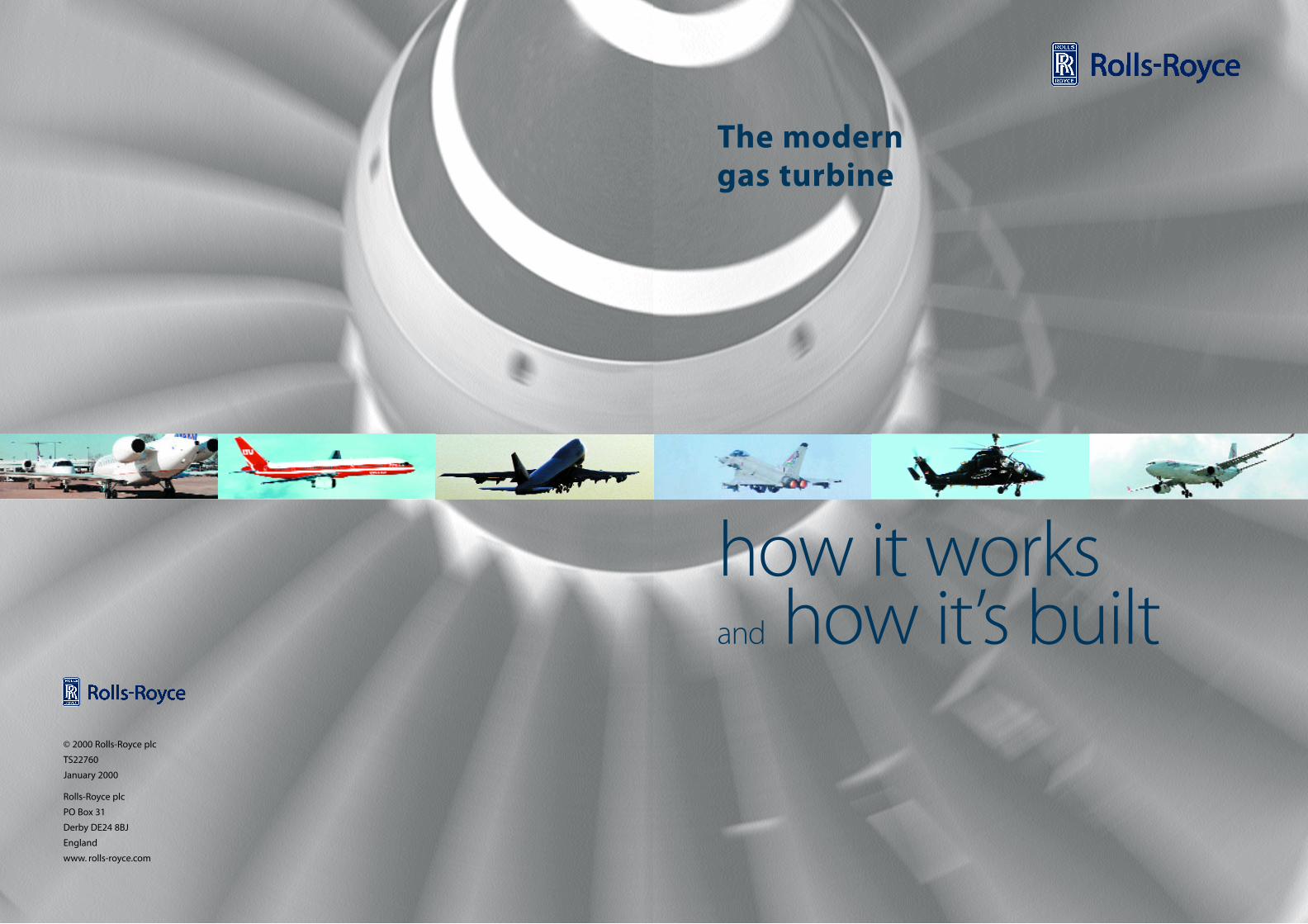
Jet propulsion
Though the principle of jet propulsion
had been demonstrated in the first
century AD by Hero of Alexandria,
the practical gas turbine, popularly
called the ‘jet’ engine, had to wait for
the 1930s and the genius of Frank
Whittle. Originally designed for aircraft
propulsion, the gas turbine is now
adapted for marine propulsion, power
generation and gas & oil pumping,
all benefiting from its inherent high
power and small size.
How does a gas turbine work?
Like the motor car engine, the gas
turbine is an internal combustion
engine. In both, air is compressed,
fuel added, the mixture ignited, and
the rapid expansion of the resultant
hot gas produces the power. However,
combustion in a motor car engine is
intermittent and the expanding gas
produces shaft power through a piston
and crank, whereas in a jet engine
combustion is continuous and its power
results from expanding gas being
forced out of the rear of the engine.
One of Newton’s principles is that to
every action there is an equal and
opposite reaction. The expanding gas
flow is an action which creates a reaction
of equivalent force. This force - thrust -
is transmitted through the engine to
the aircraft, propelling it through the
air. An inflated party balloon can
demonstrate this: with the neck closed,
the air inside presses equally in all
directions; open the neck, and the air is
released as an action, creating a
reaction on the opposite surface of the
balloon which drives it forward.
Thrust is measured in pounds force (lbf ),
kilograms force (kgf ), or Newtons (N).
The gas turbine - how it works
54
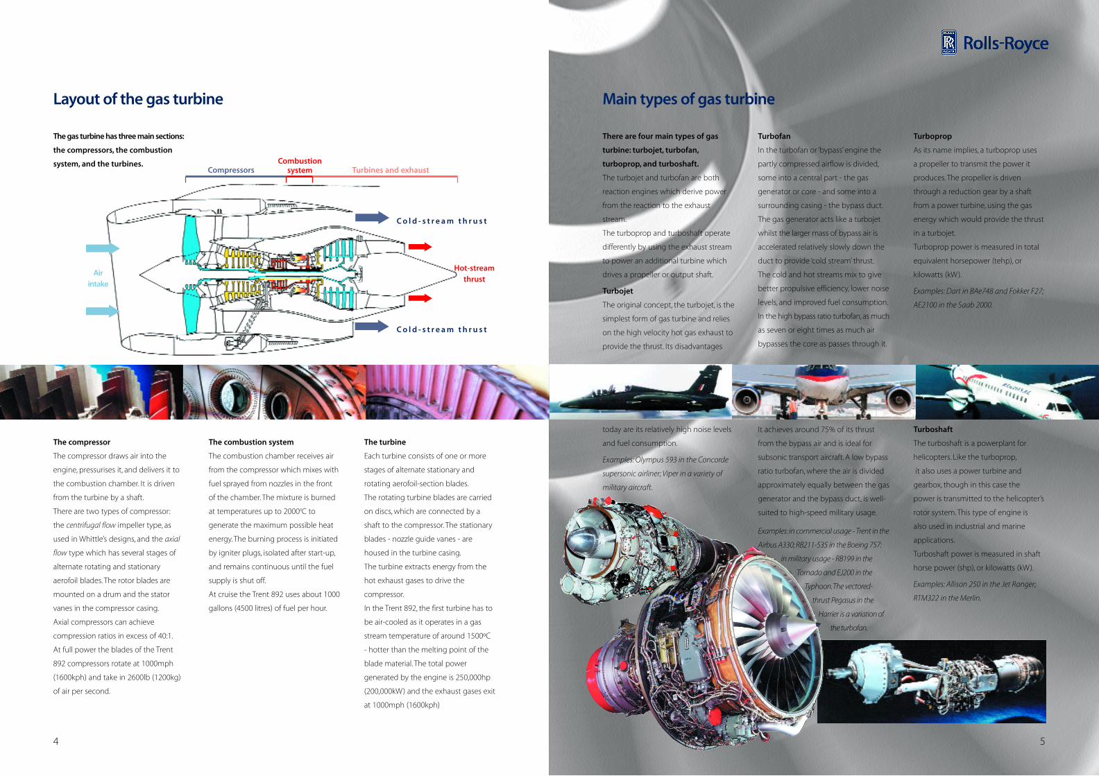
There are four main types of gas
turbine: turbojet, turbofan,
turboprop, and turboshaft.
The turbojet and turbofan are both
reaction engines which derive power
from the reaction to the exhaust
stream.
The turboprop and turboshaft operate
differently by using the exhaust stream
to power an additional turbine which
drives a propeller or output shaft.
Turbojet
The original concept, the turbojet, is the
simplest form of gas turbine and relies
on the high velocity hot gas exhaust to
provide the thrust. Its disadvantages
today are its relatively high noise levels
and fuel consumption.
Examples: Olympus 593 in the Concorde
supersonic airliner; Viper in a variety of
military aircraft.
Turbofan
In the turbofan or ‘bypass’ engine the
partly compressed airflow is divided,
some into a central part - the gas
generator or core - and some into a
surrounding casing - the bypass duct.
The gas generator acts like a turbojet
whilst the larger mass of bypass air is
accelerated relatively slowly down the
duct to provide ‘cold stream’ thrust.
The cold and hot streams mix to give
better propulsive efficiency, lower noise
levels, and improved fuel consumption.
In the high bypass ratio turbofan, as much
as seven or eight times as much air
bypasses the core as passes through it.
It achieves around 75% of its thrust
from the bypass air and is ideal for
subsonic transport aircraft. A low bypass
ratio turbofan, where the air is divided
approximately equally between the gas
generator and the bypass duct, is well-
suited to high-speed military usage.
Examples: in commercial usage - Trent in the
Airbus A330; RB211-535 in the Boeing 757:
in military usage - RB199 in the
Tornado and EJ200 in the
Typhoon.The vectored-
thrust Pegasus in the
Harrier is a variation of
the turbofan.
Turboprop
As its name implies, a turboprop uses
a propeller to transmit the power it
produces. The propeller is driven
through a reduction gear by a shaft
from a power turbine, using the gas
energy which would provide the thrust
in a turbojet.
Turboprop power is measured in total
equivalent horsepower (tehp), or
kilowatts (kW).
Examples: Dart in BAe748 and Fokker F27;
AE2100 in the Saab 2000.
Turboshaft
The turboshaft is a powerplant for
helicopters. Like the turboprop,
it also uses a power turbine and
gearbox, though in this case the
power is transmitted to the helicopter’s
rotor system. This type of engine is
also used in industrial and marine
applications.
Turboshaft power is measured in shaft
horse power (shp), or kilowatts (kW).
Examples: Allison 250 in the Jet Ranger;
RTM322 in the Merlin.
Main types of gas turbineLayout of the gas turbine
The compressor
The compressor draws air into the
engine, pressurises it, and delivers it to
the combustion chamber. It is driven
from the turbine by a shaft.
There are two types of compressor:
the centrifugal flow impeller type, as
used in Whittle’s designs, and the axial
flow type which has several stages of
alternate rotating and stationary
aerofoil blades. The rotor blades are
mounted on a drum and the stator
vanes in the compressor casing.
Axial compressors can achieve
compression ratios in excess of 40:1.
At full power the blades of the Trent
892 compressors rotate at 1000mph
(1600kph) and take in 2600lb (1200kg)
of air per second.
The combustion system
The combustion chamber receives air
from the compressor which mixes with
fuel sprayed from nozzles in the front
of the chamber. The mixture is burned
at temperatures up to 20000C to
generate the maximum possible heat
energy. The burning process is initiated
by igniter plugs, isolated after start-up,
and remains continuous until the fuel
supply is shut off.
At cruise the Trent 892 uses about 1000
gallons (4500 litres) of fuel per hour.
The turbine
Each turbine consists of one or more
stages of alternate stationary and
rotating aerofoil-section blades.
The rotating turbine blades are carried
on discs, which are connected by a
shaft to the compressor. The stationary
blades - nozzle guide vanes - are
housed in the turbine casing.
The turbine extracts energy from the
hot exhaust gases to drive the
compressor.
In the Trent 892, the first turbine has to
be air-cooled as it operates in a gas
stream temperature of around 1500ºC
- hotter than the melting point of the
blade material. The total power
generated by the engine is 250,000hp
(200,000kW) and the exhaust gases exit
at 1000mph (1600kph)
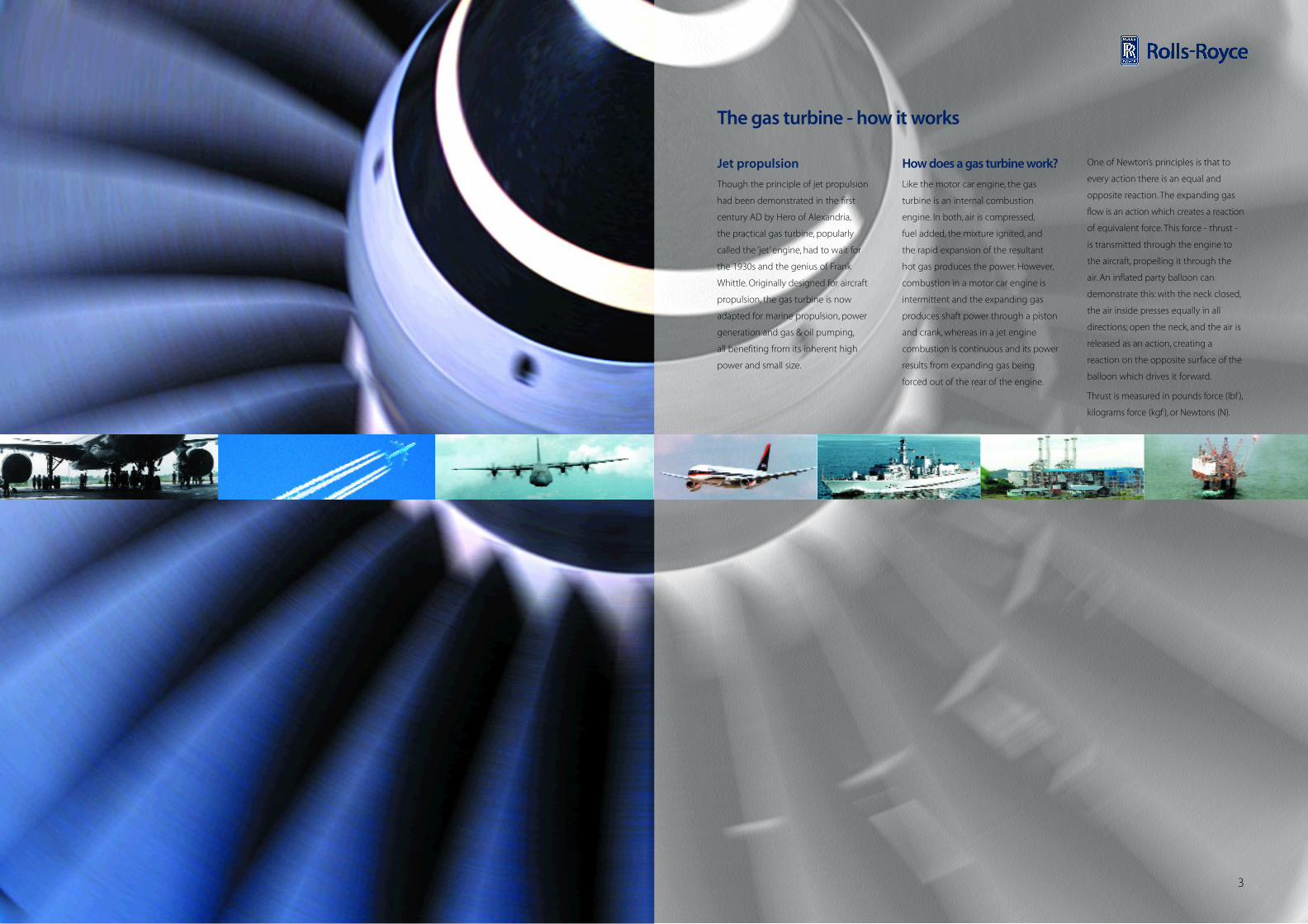
The gas turbine has three main sections:
the compressors, the combustion
system, and the turbines.
Airintake
Hot-streamthrust
Combustionsystem Turbines and exhaustCompressors
C o l d - s t r e a m t h r u s t
C o l d - s t r e a m t h r u s t
�
�
�
�
�
�
76
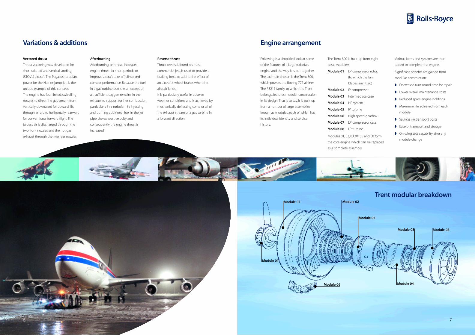
Following is a simplified look at some
of the features of a large turbofan
engine and the way it is put together.
The example chosen is the Trent 800,
which powers the Boeing 777 airliner.
The RB211 family, to which the Trent
belongs, features modular construction
in its design. That is to say, it is built up
from a number of large assemblies
known as ‘modules’, each of which has
its individual identity and service
history.
The Trent 800 is built-up from eight
basic modules:
Module 01 LP compressor rotor,
(to which the fan
blades are fitted)
Module 02 IP compressor
Module 03 Intermediate case
Module 04 HP system
Module 05 IP turbine
Module 06 High speed gearbox
Module 07 LP compressor case
Module 08 LP turbine
Modules 01, 02, 03, 04, 05 and 08 form
the core engine which can be replaced
as a complete assembly.
Various items and systems are then
added to complete the engine.
Significant benefits are gained from
modular construction:
� Decreased turn-round time for repair
� Lower overall maintenance costs
� Reduced spare engine holdings
� Maximum life achieved from each
module
� Savings on transport costs
� Ease of transport and storage
� On-wing test capability after any
module change
Engine arrangement
Trent modular breakdown
Variations & additions
Module 01
Module 02
Module 03
Module 04
Module 05 Module 08
Module 06
Module 07
Vectored thrust
Thrust vectoring was developed for
short take-off and vertical landing
(STOVL) aircraft. The Pegasus turbofan,
power for the Harrier ‘jump-jet’, is the
unique example of this concept.
The engine has four linked, swivelling
nozzles to direct the gas stream from
vertically downward for upward lift,
through an arc to horizontally rearward
for conventional forward flight. The
bypass air is discharged through the
two front nozzles and the hot gas
exhaust through the two rear nozzles.
Afterburning
Afterburning, or reheat, increases
engine thrust for short periods to
improve aircraft take-off, climb and
combat performance. Because the fuel
in a gas turbine burns in an excess of
air, sufficient oxygen remains in the
exhaust to support further combustion,
particularly in a turbofan. By injecting
and burning additional fuel in the jet
pipe, the exhaust velocity and
consequently the engine thrust is
increased
Reverse thrust
Thrust reversal, found on most
commercial jets, is used to provide a
braking force to add to the effect of
an aircraft’s wheel-brakes when the
aircraft lands.
It is particularly useful in adverse
weather conditions and is achieved by
mechanically deflecting some or all of
the exhaust stream of a gas turbine in
a forward direction.
98
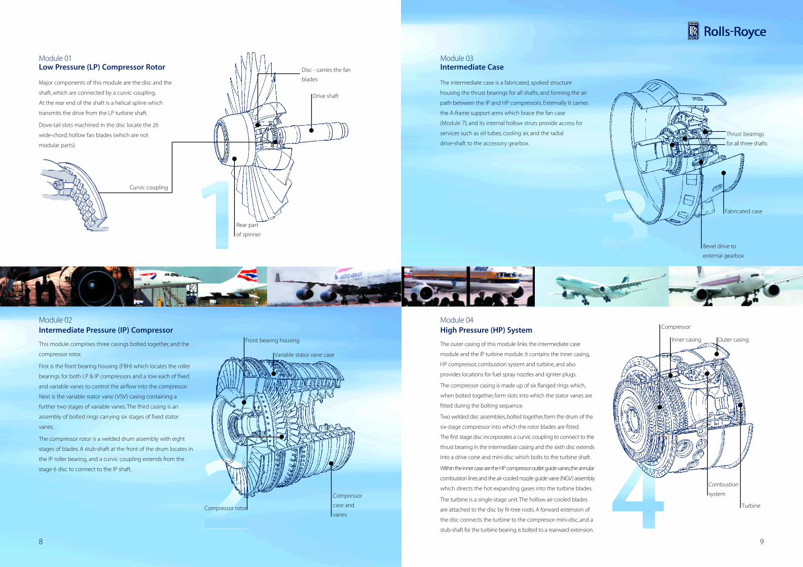
Module 03 Intermediate Case
Module 04 High Pressure (HP) System
Major components of this module are the disc and the
shaft, which are connected by a curvic coupling.
At the rear end of the shaft is a helical spline which
transmits the drive from the LP turbine shaft.
Dove-tail slots machined in the disc locate the 26
wide-chord, hollow fan blades (which are not
modular parts).
Module 01 Low Pressure (LP) Compressor Rotor
This module comprises three casings bolted together, and the
compressor rotor.
First is the front bearing housing (FBH) which locates the roller
bearings for both LP & IP compressors and a row each of fixed
and variable vanes to control the airflow into the compressor.
Next is the variable stator vane (VSV) casing containing a
further two stages of variable vanes. The third casing is an
assembly of bolted rings carrying six stages of fixed stator
vanes.
The compressor rotor is a welded drum assembly with eight
stages of blades. A stub-shaft at the front of the drum locates in
the IP roller bearing, and a curvic coupling extends from the
stage 6 disc to connect to the IP shaft.
Module 02 Intermediate Pressure (IP) Compressor
The outer casing of this module links the intermediate case
module and the IP turbine module. It contains the inner casing,
HP compressor, combustion system and turbine, and also
provides locations for fuel spray nozzles and igniter plugs.
The compressor casing is made up of six flanged rings which,
when bolted together, form slots into which the stator vanes are
fitted during the bolting sequence.
Two welded disc assemblies, bolted together, form the drum of the
six-stage compressor into which the rotor blades are fitted.
The first stage disc incorporates a curvic coupling to connect to the
thrust bearing in the intermediate casing and the sixth disc extends
into a drive cone and mini-disc which bolts to the turbine shaft.
Within the inner case are the HP compressor outlet guide vanes,the annular
combustion liner,and the air-cooled nozzle guide vane (NGV) assembly
which directs the hot expanding gases into the turbine blades.
The turbine is a single-stage unit.The hollow air-cooled blades
are attached to the disc by fir-tree roots. A forward extension of
the disc connects the turbine to the compressor mini-disc, and a
stub-shaft for the turbine bearing is bolted to a rearward extension.
The intermediate case is a fabricated, spoked structure
housing the thrust bearings for all shafts, and forming the air
path between the IP and HP compressors. Externally it carries
the A-frame support arms which brace the fan case
(Module 7), and its internal hollow struts provide access for
services such as oil tubes, cooling air, and the radial
drive-shaft to the accessory gearbox.
Disc - carries the fan
blades
Drive shaft
Curvic coupling
Rear part
of spinner
Front bearing housing
Variable stator vane case
Compressor
case and
vanes
Fabricated case
Bevel drive to
external gearbox
Thrust bearings
for all three shafts
Compressor rotor
Combustion
system
Turbine
Compressor
Inner casing Outer casing
1110
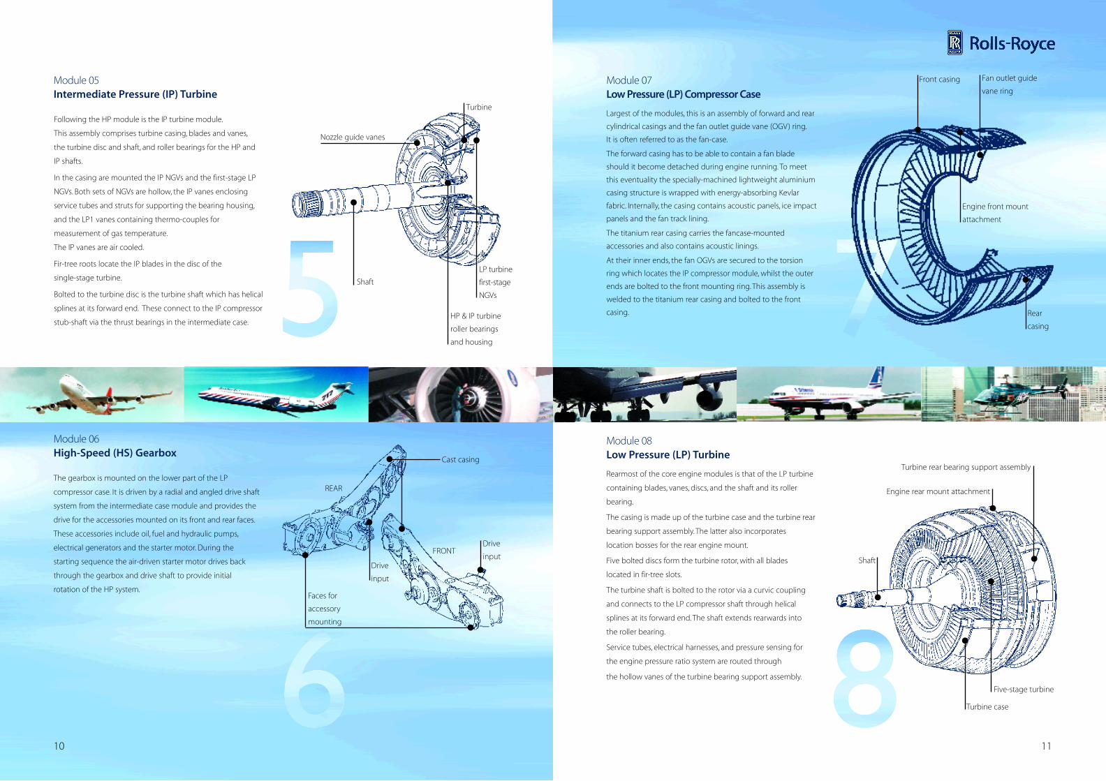
The gearbox is mounted on the lower part of the LP
compressor case. It is driven by a radial and angled drive shaft
system from the intermediate case module and provides the
drive for the accessories mounted on its front and rear faces.
These accessories include oil, fuel and hydraulic pumps,
electrical generators and the starter motor. During the
starting sequence the air-driven starter motor drives back
through the gearbox and drive shaft to provide initial
rotation of the HP system.
Module 06 High-Speed (HS) Gearbox
Largest of the modules, this is an assembly of forward and rear
cylindrical casings and the fan outlet guide vane (OGV) ring.
It is often referred to as the fan-case.
The forward casing has to be able to contain a fan blade
should it become detached during engine running. To meet
this eventuality the specially-machined lightweight aluminium
casing structure is wrapped with energy-absorbing Kevlar
fabric. Internally, the casing contains acoustic panels, ice impact
panels and the fan track lining.
The titanium rear casing carries the fancase-mounted
accessories and also contains acoustic linings.
At their inner ends, the fan OGVs are secured to the torsion
ring which locates the IP compressor module, whilst the outer
ends are bolted to the front mounting ring. This assembly is
welded to the titanium rear casing and bolted to the front
casing.
Module 07 Low Pressure (LP) Compressor Case
Following the HP module is the IP turbine module.
This assembly comprises turbine casing, blades and vanes,
the turbine disc and shaft, and roller bearings for the HP and
IP shafts.
In the casing are mounted the IP NGVs and the first-stage LP
NGVs. Both sets of NGVs are hollow, the IP vanes enclosing
service tubes and struts for supporting the bearing housing,
and the LP1 vanes containing thermo-couples for
measurement of gas temperature.
The IP vanes are air cooled.
Fir-tree roots locate the IP blades in the disc of the
single-stage turbine.
Bolted to the turbine disc is the turbine shaft which has helical
splines at its forward end. These connect to the IP compressor
stub-shaft via the thrust bearings in the intermediate case.
Module 05 Intermediate Pressure (IP) Turbine
Rearmost of the core engine modules is that of the LP turbine
containing blades, vanes, discs, and the shaft and its roller
bearing.
The casing is made up of the turbine case and the turbine rear
bearing support assembly. The latter also incorporates
location bosses for the rear engine mount.
Five bolted discs form the turbine rotor, with all blades
located in fir-tree slots.
The turbine shaft is bolted to the rotor via a curvic coupling
and connects to the LP compressor shaft through helical
splines at its forward end. The shaft extends rearwards into
the roller bearing.
Service tubes, electrical harnesses, and pressure sensing for
the engine pressure ratio system are routed through
the hollow vanes of the turbine bearing support assembly.
Module 08 Low Pressure (LP) Turbine
Nozzle guide vanes
Shaft
LP turbine
first-stage
NGVs
Turbine
HP & IP turbine
roller bearings
and housing
Five-stage turbine
Turbine case
Shaft
Turbine rear bearing support assembly
Engine rear mount attachment
Cast casing
FRONT
REAR
Faces for
accessory
mounting
Drive
inputDrive
input
Front casing
Rear
casing
Engine front mount
attachment
Fan outlet guide
vane ring
Recommended