Embed Size (px)
Citation preview
INFRASTRUCTURE
MINING & METALS
NUCLEAR, SECURITY & ENVIRONMENTAL
OIL, GAS & CHEMICALS
Modern Gas Turbine Combined Cycle
About Bechtel Bechtel is among the most respected engineering, project management, and construction companies in the world. We stand apart for our ability to get the job done right—no matter how big, how complex, or how remote. Bechtel operates through four global business units that specialize in infrastructure; mining and metals; nuclear, security and environmental; and oil, gas, and chemicals. Since its founding in 1898, Bechtel has worked on more than 25,000 projects in 160 countries on all seven continents. Today, our 58,000 colleagues team with customers, partners, and suppliers on diverse projects in nearly 40 countries.
S. C. GÜLEN
The indisputable king of the fossil fired electric power gen-eration realm is the gas turbine combined cycle (GTCC)power plant with modern F-, G-, H- and J-class machines.At 60+% net thermal efficiency (officially clocked in a
commercial installation in 2011), it is ten percentage pointsahead of its nearest challenger (an ultra-supercritical pulver-ized coal power plant). As such, especially under the light ofthe recent discovery of abundant shale gas reserves, natural gasburning GTCC is all but certain to be a major ingredient in apower generation mix for the foreseeable carbon-averse future.
The seventieth anniversary of the first modern mass-pro-duced jet engine (Junkers Jumo-004 turbojet powering theworld’s first jet fighter, Messerschmitt 262) presents an aptoccasion to recap the evolution of the technology and gauge itsfuture potential. In order to avoid hyperbole and commercial-ism, it is imperative to ground the discussion in firm theory (tothe extent possible in a short article) and knowledge of history(sometimes the obscure aspects of it).
BeginningsAnselm Franz’s Jumo-004 was a culmination of work done bymany giants in the field, primarily Hans von Ohain and SirFrank Whittle, who walked in the footsteps of earlier inventorsfrom 18th and 19th centuries. In terms of basic engine architec-ture, Jumo-004 was no different from its modern descendants,including can-annular combustor and stacked-wheel rotor con-struction with serrated Hirth couplings (the same as in latest H-class units of one OEM).
The interested reader can find many excellent referencesdiscussing the engine in detail. Suffice to say that its hollowturbine blades, manufactured from folded and welded 12-%chrome alloy, were cooled from air bled from the compressor.While built around a modest cycle with pressure ratio (PR) ofonly about 3 and turbine inlet temperature (TIT) of 1,427 F(775 C), it is not a big stretch to claim that Franz and team (notto mention the competing teams in UK and USA at the time)could have designed a bona fide E-class gas turbine before1950 if they had the right materials – in addition to removal ofrestrictions imposed by wartime considerations.
After all, when one looks beyond its intricate accessory sys-tems for lubrication, fuel delivery, cranking, etc., the gas tur-bine is an extremely simple machine designed to compress air,add fuel to react with oxygen in the air and then expand themixture of reaction products. In essence, it is the practicalembodiment of the Brayton (Joule) cycle, which, like all heatengine cycles, is a valiant albeit very poor attempt to replicatethe ultimate heat engine cycle: the Carnot cycle.
As such, gas turbine performance is dictated by two cycleparameters: PR and TIT. On an ideal (commonly referred to asair-standard) Brayton cycle basis, the former dictates the cycleefficiency and the latter the cycle specific work output. In realcycles with aero-thermodynamic, hydrodynamic, mechanicaland cooling losses, both have positive impact on simple cycleefficiency while TIT is of prime importance to the combinedBrayton-Rankine cycle efficiency. The bottom line is that thereis one and only one path to further improvement of simple orcombined gas turbine cycle efficiency: ever increasing TITwith commensurate rise in cycle PR. This was already predict-
ed at the dawn of the jet age by Adolf Meyer in his 1939 paperpresented at a meeting of the Institution of MechanicalEngineers in London, UK.
Carnot LimitThe Carnot cycle is the translation of the second law of ther-modynamics into engineering jargon: One cannot build a heatengine operating in a cycle and more efficient than the equiva-lent Carnot engine. The impossibility of even approaching theCarnot limit in practice stems from the near impossibility ofattaining heat transfer at constant temperature (yes, there is anexception and it will appear later in the narrative). Thus, eachgas turbine Brayton cycle with known PR and TIT can be trans-lated into its Carnot-equivalent via mean-effective heat additionand heat rejection temperatures, METH and METL, respective-ly (Figure1). Following the standard cycle notation, then
which, in fact, is the first response to the inquiry of ideal effi-ciency of a given cycle. (Note how it completely ignores thecycle PR, which, in fact, is the primary driver of efficiency).Since the gas turbine industry is not in the business of buildingCarnot engines, what good is Eq. [3] to a practitioner? As itwill be demonstrated below, Eq. [3] is a potent tool to estimateactual gas turbine performance. Furthermore, it highlights thefact that low temperature (heat rejection) is as important, if notmore so, for achieving the highest possible cycle efficiencies.With the focus on the high temperature (heat addition) side ofthe cycle, this fact is sometimes ignored.
Which Temperature?First consider the current gas turbine technology landscapewhere the main classification parameter is TIT (Figure 2). Interms of sheer numbers, it is dominated by standard E (1,300 CTIT) and F class (1,400 C) units with air-cooled (utilizing com-pressor bleeds) turbine hot gas path (HGP). Recent introductionof advanced F-class machines (one OEM refers to them as “H”class, herein referred to as H-OLAC or H with open-loop air-cooling to distinguish it from the steam-cooled H-class) broughtthe standard F-class into the realm of steam-cooled G- and H-class technologies (1,500 C TIT). The latter class (herein H-CLSC or H with closed-loop steam cooling but better known asthe H-System per its OEM) with six units in commercial oper-ation since 2003 is currently not offered by the OEM. However,it has a special place in the gas turbine technology map.
Apart from the reheat gas turbine (labeled as sequen-tial combustion by its OEM) with much higher number ofunits in commercial operation, H-System with two fully
GAS TURBINES
MODERN GAS TURBINE COMBINED CYCLENET THERMAL EFFICIENCY RATINGS OF 60% ARE HERE — WHAT’S NEXT?
November/December 2013 • Turbomachinery Internationalwww.turbomachinerymag.com
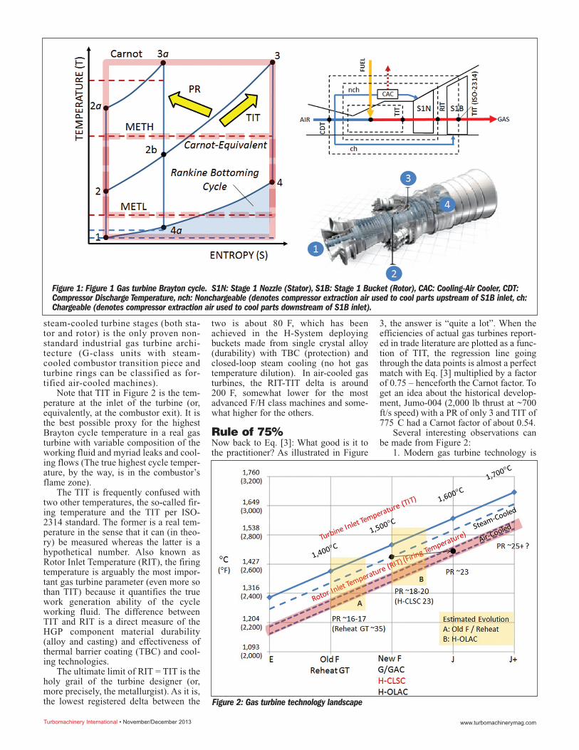
steam-cooled turbine stages (both sta-tor and rotor) is the only proven non-standard industrial gas turbine archi-tecture (G-class units with steam-cooled combustor transition piece andturbine rings can be classified as for-tified air-cooled machines).
Note that TIT in Figure 2 is the tem-perature at the inlet of the turbine (or,equivalently, at the combustor exit). It isthe best possible proxy for the highestBrayton cycle temperature in a real gasturbine with variable composition of theworking fluid and myriad leaks and cool-ing flows (The true highest cycle temper-ature, by the way, is in the combustor’sflame zone).
The TIT is frequently confused withtwo other temperatures, the so-called fir-ing temperature and the TIT per ISO-2314 standard. The former is a real tem-perature in the sense that it can (in theo-ry) be measured whereas the latter is ahypothetical number. Also known asRotor Inlet Temperature (RIT), the firingtemperature is arguably the most impor-tant gas turbine parameter (even more sothan TIT) because it quantifies the truework generation ability of the cycleworking fluid. The difference betweenTIT and RIT is a direct measure of theHGP component material durability(alloy and casting) and effectiveness ofthermal barrier coating (TBC) and cool-ing technologies.
The ultimate limit of RIT = TIT is theholy grail of the turbine designer (or,more precisely, the metallurgist). As it is,the lowest registered delta between the
two is about 80 F, which has beenachieved in the H-System deployingbuckets made from single crystal alloy(durability) with TBC (protection) andclosed-loop steam cooling (no hot gastemperature dilution). In air-cooled gasturbines, the RIT-TIT delta is around200 F, somewhat lower for the mostadvanced F/H class machines and some-what higher for the others.
Rule of 75%Now back to Eq. [3]: What good is it tothe practitioner? As illustrated in Figure
3, the answer is “quite a lot”. When theefficiencies of actual gas turbines report-ed in trade literature are plotted as a func-tion of TIT, the regression line goingthrough the data points is almost a perfectmatch with Eq. [3] multiplied by a factorof 0.75 – henceforth the Carnot factor. Toget an idea about the historical develop-ment, Jumo-004 (2,000 lb thrust at ~700ft/s speed) with a PR of only 3 and TIT of775 C had a Carnot factor of about 0.54.
Several interesting observations canbe made from Figure 2:
1. Modern gas turbine technology is
Turbomachinery International • November/December 2013 www.turbomachinerymag.com
Figure 1: Figure 1 Gas turbine Brayton cycle. S1N: Stage 1 Nozzle (Stator), S1B: Stage 1 Bucket (Rotor), CAC: Cooling-Air Cooler, CDT:Compressor Discharge Temperature, nch: Nonchargeable (denotes compressor extraction air used to cool parts upstream of S1B inlet, ch:Chargeable (denotes compressor extraction air used to cool parts downstream of S1B inlet).
Figure 2: Gas turbine technology landscape
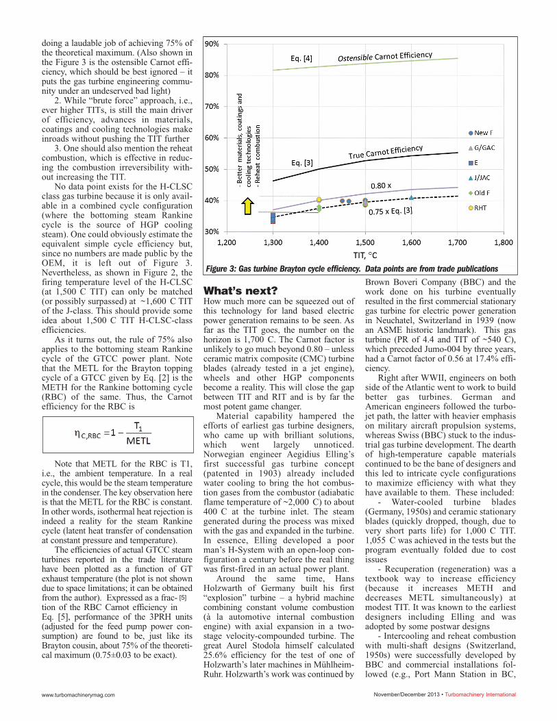
doing a laudable job of achieving 75% ofthe theoretical maximum. (Also shown inthe Figure 3 is the ostensible Carnot effi-ciency, which should be best ignored – itputs the gas turbine engineering commu-nity under an undeserved bad light)
2. While “brute force” approach, i.e.,ever higher TITs, is still the main driverof efficiency, advances in materials,coatings and cooling technologies makeinroads without pushing the TIT further
3. One should also mention the reheatcombustion, which is effective in reduc-ing the combustion irreversibility with-out increasing the TIT.
No data point exists for the H-CLSCclass gas turbine because it is only avail-able in a combined cycle configuration(where the bottoming steam Rankinecycle is the source of HGP coolingsteam). One could obviously estimate theequivalent simple cycle efficiency but,since no numbers are made public by theOEM, it is left out of Figure 3.Nevertheless, as shown in Figure 2, thefiring temperature level of the H-CLSC(at 1,500 C TIT) can only be matched(or possibly surpassed) at ~1,600 C TITof the J-class. This should provide someidea about 1,500 C TIT H-CLSC-classefficiencies.
As it turns out, the rule of 75% alsoapplies to the bottoming steam Rankinecycle of the GTCC power plant. Notethat the METL for the Brayton toppingcycle of a GTCC given by Eq. [2] is theMETH for the Rankine bottoming cycle(RBC) of the same. Thus, the Carnotefficiency for the RBC is
Note that METL for the RBC is T1,i.e., the ambient temperature. In a realcycle, this would be the steam temperaturein the condenser. The key observation hereis that the METL for the RBC is constant.In other words, isothermal heat rejection isindeed a reality for the steam Rankinecycle (latent heat transfer of condensationat constant pressure and temperature).
The efficiencies of actual GTCC steamturbines reported in the trade literaturehave been plotted as a function of GTexhaust temperature (the plot is not showndue to space limitations; it can be obtainedfrom the author). Expressed as a frac-tion of the RBC Carnot efficiency inEq. [5], performance of the 3PRH units(adjusted for the feed pump power con-sumption) are found to be, just like itsBrayton cousin, about 75% of the theoreti-cal maximum (0.75±0.03 to be exact).
What’s next?How much more can be squeezed out ofthis technology for land based electricpower generation remains to be seen. Asfar as the TIT goes, the number on thehorizon is 1,700 C. The Carnot factor isunlikely to go much beyond 0.80 – unlessceramic matrix composite (CMC) turbineblades (already tested in a jet engine),wheels and other HGP componentsbecome a reality. This will close the gapbetween TIT and RIT and is by far themost potent game changer.
Material capability hampered theefforts of earliest gas turbine designers,who came up with brilliant solutions,which went largely unnoticed.Norwegian engineer Aegidius Elling’sfirst successful gas turbine concept(patented in 1903) already includedwater cooling to bring the hot combus-tion gases from the combustor (adiabaticflame temperature of ~2,000 C) to about400 C at the turbine inlet. The steamgenerated during the process was mixedwith the gas and expanded in the turbine.In essence, Elling developed a poorman’s H-System with an open-loop con-figuration a century before the real thingwas first-fired in an actual power plant.
Around the same time, HansHolzwarth of Germany built his first“explosion” turbine – a hybrid machinecombining constant volume combustion(à la automotive internal combustionengine) with axial expansion in a two-stage velocity-compounded turbine. Thegreat Aurel Stodola himself calculated25.6% efficiency for the test of one ofHolzwarth’s later machines in Mühlheim-Ruhr. Holzwarth’s work was continued by
Brown Boveri Company (BBC) and thework done on his turbine eventuallyresulted in the first commercial stationarygas turbine for electric power generationin Neuchatel, Switzerland in 1939 (nowan ASME historic landmark). This gasturbine (PR of 4.4 and TIT of ~540 C),which preceded Jumo-004 by three years,had a Carnot factor of 0.56 at 17.4% effi-ciency.
Right after WWII, engineers on bothside of the Atlantic went to work to buildbetter gas turbines. German andAmerican engineers followed the turbo-jet path, the latter with heavier emphasison military aircraft propulsion systems,whereas Swiss (BBC) stuck to the indus-trial gas turbine development. The dearthof high-temperature capable materialscontinued to be the bane of designers andthis led to intricate cycle configurationsto maximize efficiency with what theyhave available to them. These included:
- Water-cooled turbine blades(Germany, 1950s) and ceramic stationaryblades (quickly dropped, though, due tovery short parts life) for 1,000 C TIT.1,055 C was achieved in the tests but theprogram eventually folded due to costissues
- Recuperation (regeneration) was atextbook way to increase efficiency(because it increases METH anddecreases METL simultaneously) atmodest TIT. It was known to the earliestdesigners including Elling and wasadopted by some postwar designs
- Intercooling and reheat combustionwith multi-shaft designs (Switzerland,1950s) were successfully developed byBBC and commercial installations fol-lowed (e.g., Port Mann Station in BC,
November/December 2013 • Turbomachinery Internationalwww.turbomachinerymag.com
[5]
Figure 3: Gas turbine Brayton cycle efficiency. Data points are from trade publications
Canada)Water cooling was looked at later in
the 1980s in the U.S. and dropped again.Eventually, though, steam cooling andreheat combustion made their way intocommercial products (the latter muchmore successfully). Recuperation andintercooling are also available in com-mercial products, albeit in smaller aero-derivative gas turbines with high PR,where they make the biggest impact insimple cycle configuration.
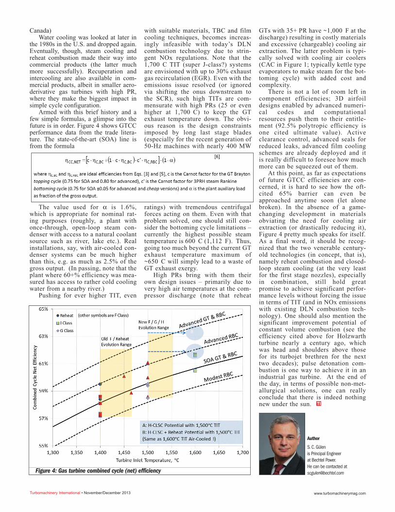
Armed with this brief history and afew simple formulas, a glimpse into thefuture is in order. Figure 4 shows GTCCperformance data from the trade litera-ture. The state-of-the-art (SOA) line isfrom the formula
The value used for α is 1.6%,which is appropriate for nominal rat-ing purposes (roughly, a plant withonce-through, open-loop steam con-denser with access to a natural coolantsource such as river, lake etc.). Realinstallations, say, with air-cooled con-denser systems can be much higherthan this, e.g. as much as 2.5% of thegross output. (In passing, note that theplant where 60+% efficiency was mea-sured has access to rather cold coolingwater from a nearby river.)
Pushing for ever higher TIT, even
with suitable materials, TBC and filmcooling techniques, becomes increas-ingly infeasible with today’s DLNcombustion technology due to strin-gent NOx regulations. Note that the1,700 C TIT (super J-class?) systemsare envisioned with up to 30% exhaustgas recirculation (EGR). Even with theemissions issue resolved (or ignoredvia shifting the onus downstream tothe SCR), such high TITs are com-mensurate with high PRs (25 or evenhigher at 1,700 C) to keep the GTexhaust temperature down. The obvi-ous reason is the design constraintsimposed by long last stage blades(especially for the recent generation of50-Hz machines with nearly 400 MW
ratings) with tremendous centrifugalforces acting on them. Even with thatproblem solved, one should still con-sider the bottoming cycle limitations –currently the highest possible steamtemperature is 600 C (1,112 F). Thus,going too much beyond the current GTexhaust temperature maximum of~650 C will simply lead to a waste ofGT exhaust exergy.
High PRs bring with them theirown design issues – primarily due tovery high air temperatures at the com-pressor discharge (note that reheat
GTs with 35+ PR have ~1,000 F at thedischarge) resulting in costly materialsand excessive (chargeable) cooling airextraction. The latter problem is typi-cally solved with cooling air coolers(CAC in Figure 1; typically kettle typeevaporators to make steam for the bot-toming cycle) with added cost andcomplexity.
There is not a lot of room left incomponent efficiencies; 3D airfoildesigns enabled by advanced numeri-cal codes and computationalresources push them to their entitle-ment (92.5% polytropic efficiency isone cited ultimate value). Activeclearance control, advanced seals forreduced leaks, advanced film coolingschemes are already deployed and itis really difficult to foresee how muchmore can be squeezed out of them.
At this point, as far as expectationsof future GTCC efficiencies are con-cerned, it is hard to see how the oft-cited 65% barrier can even beapproached anytime soon (let alonebroken). In the absence of a game-changing development in materialsobviating the need for cooling airextraction (or drastically reducing it),Figure 4 pretty much speaks for itself.As a final word, it should be recog-nized that the two venerable century-old technologies (in concept, that is),namely reheat combustion and closed-loop steam cooling (at the very leastfor the first stage nozzles), especiallyin combination, still hold greatpromise to achieve significant perfor-mance levels without forcing the issuein terms of TIT (and in NOx emissionswith existing DLN combustion tech-nology). One should also mention thesignificant improvement potential ofconstant volume combustion (see theefficiency cited above for Holzwarthturbine nearly a century ago, whichwas head and shoulders above thosefor its turbojet brethren for the nexttwo decades); pulse detonation com-bustion is one way to achieve it in anindustrial gas turbine. At the end ofthe day, in terms of possible non-met-allurgical solutions, one can reallyconclude that there is indeed nothingnew under the sun. TI
Turbomachinery International • November/December 2013 www.turbomachinerymag.com
Figure 4: Gas turbine combined cycle (net) efficiency
Author
S. C. Gülenis Principal Engineerat Bechtel Power.He can be contacted at [email protected]