ST320
WATERPROOF PROXIMITY ACCESS CONTROL SYSTEM OPERATION AND
INSTALLATION MANUAL
SOCA TECHNOLOGY CO., LTD. COPYRIGHT 2005 February
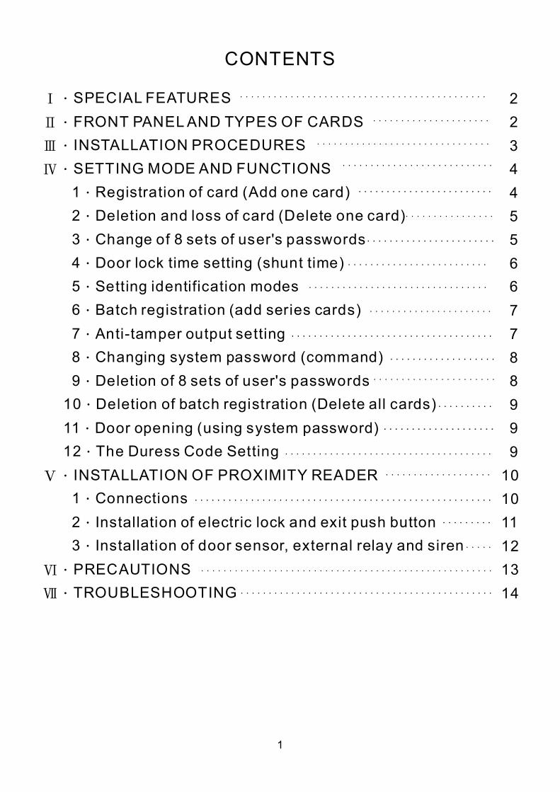
CONTENTS
Ⅰ
Ⅱ
Ⅲ
Ⅳ
Ⅴ
Ⅵ
Ⅶ
.
.
.
.
.
.
.
.
.
.
.
.
.
.
.
.
.
.
.
.
.
.
SPECIAL FEATURES FRONT PANELAND TYPES OF CARDS INSTALLATION PROCEDURES SETTING MODE AND FUNCTIONS 1 Registration of card (Add one card) 2 Deletion and loss of card (Delete one card) 3 Change of 8 sets of user's passwords 4 Door lock time setting (shunt time) 5 Setting identification modes 6 Batch registration (add series cards) 7 Antitamper output setting 8 Changing system password (command) 9 Deletion of 8 sets of user's passwords 10 Deletion of batch registration (Delete all cards) 11 Door opening (using system password) 12 The Duress Code Setting INSTALLATION OF PROXIMITY READER 1 Connections 2 Installation of electric lock and exit push button 3 Installation of door sensor, external relay and siren PRECAUTIONS TROUBLESHOOTING
1
2 2 3 4 4 5 5 6 6 7 7 8 8 9 9 9 10 10 11 12 13 14
ST320 Mode Setting
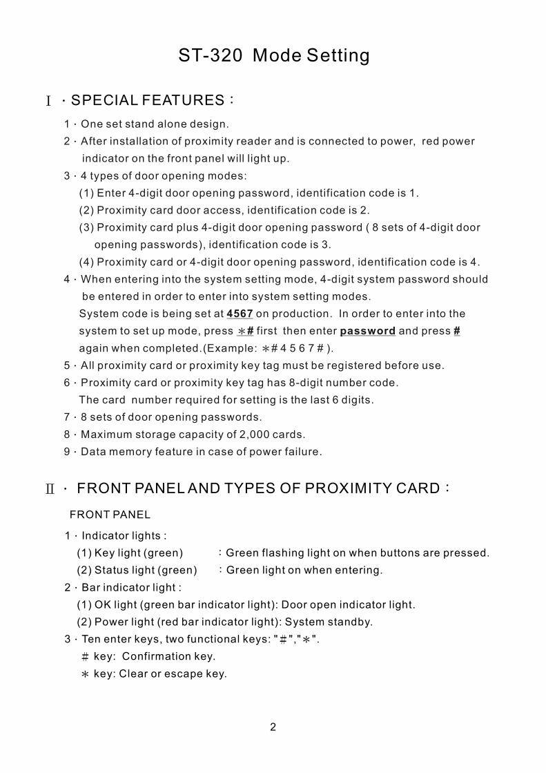
Ⅰ. : SPECIAL FEATURES 1 One set stand alone design. 2 After installation of proximity reader and is connected to power power
indicator on the front panel will light up. 3 4 types of door opening modes:
(1) Enter 4digit door opening password, identification code is 1. (2) Proximity card door access, identification code is 2. (3) Proximity card plus 4digit door opening password ( 8
opening passwords), identification code is 3. (4) Proximity card or 4digit door opening password, identification
4 When entering into the system setting mode, 4digit system be entered in order to enter into system setting System code is being set at on production. In order to enter
to set up mode, press first then enter again when completed.(Example: # 4 5 6 7 # ).
5 All proximity card or proximity key tag must be registered before 6 Proximity card or proximity key tag has 8digit number code.
The card number required for setting is the last 6 digits. 7 8 sets of door opening passwords. 8 Maximum storage capacity of 2,000 cards. 9 Data memory feature in case of power failure.
, red
sets of 4digit door
code is 4. password should
modes. into the
system and press
use.
4567 # password * #
*
.
.
.
.
.
.
.
.
.
Ⅱ. : FRONT PANELAND TYPES OF PROXIMITY CARD
FRONT PANEL
1 Indicator lights : (1) Key light (green) Green flashing light on when (2) Status light (green) Green light on when entering.
2 Bar indicator light : (1) OK light (green bar indicator light): Door open indicator light. (2) Power light (red bar indicator light): System standby.
3 Ten enter keys, two functional keys: " "," ". key: Confirmation key. key: Clear or escape key.
.
:
:
.
.
buttons are pressed.
# *
#
*
2
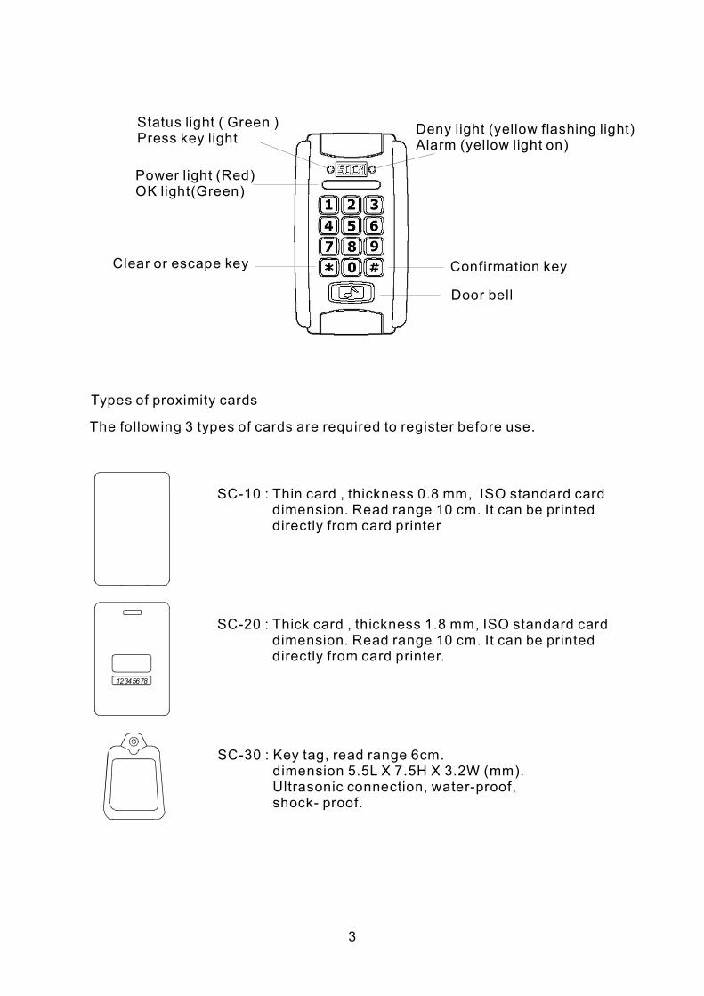
Status light ( Green ) Press key light
Power light (Red) OK light(Green)
Clear or escape key
Deny light (yellow flashing light) Alarm (yellow light on)
Confirmation key
Door bell
Types of proximity cards
The following 3 types of cards are required to register before use.
12345678
SC10 : Thin card , thickness 0.8 mm, ISO standard card Read range 10 cm. It can be printed
directly from card printer dimension.
SC20 : Thick card , thickness 1.8 mm, dimension. Read range 10 cm. It can be printed directly from card printer.
ISO standard card
SC30 : Key tag, read range 6cm. dimension 5.5L X 7.5H X 3.2W (mm). Ultrasonic connection, waterproof, shock proof.
3
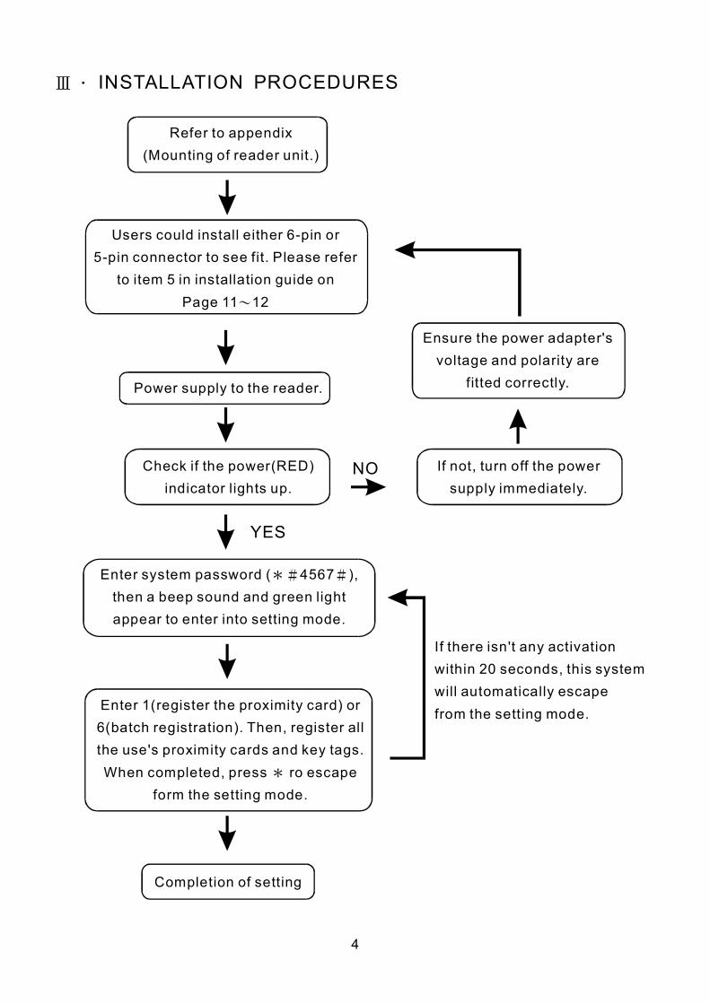
Ⅲ. INSTALLATION PROCEDURES
4
Power supply to the reader.
Completion of setting
Check if the power(RED) indicator lights up.
If not, turn off the power supply immediately.
Enter system password ( 4567 ), then a beep sound and green light appear to enter into setting mode.
*# #
Enter 1(register the proximity card) or 6(batch registration). Then, register all the use's proximity cards and key tags. When completed, press ro escape
form the setting mode. *
Refer to appendix (Mounting of reader unit.)
Users could install either 6pin or 5pin connector to see fit. Please refer
to item 5 in installation guide on 11 12 Page ~
Ensure the power adapter's voltage and polarity are
fitted correctly.
YES
If there isn't any activation within 20 seconds, this system will automatically escape from the setting mode.
NO
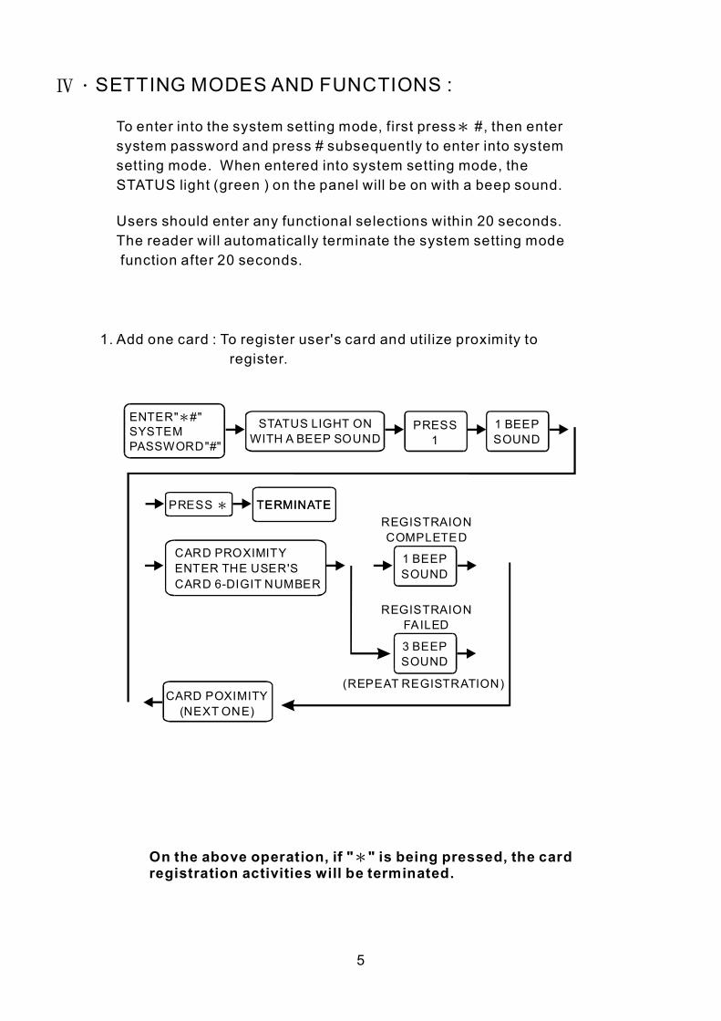
Ⅳ.SETTING MODES AND FUNCTIONS :
To enter into the system setting mode, first press #, then enter system password and press # subsequently to enter into system setting mode. When entered into system setting mode, the STATUS light (green ) on the panel will be on with a beep sound.
*
Users should enter any functional selections within 20 seconds. The reader will automatically terminate the system setting mode function after 20 seconds.
1. Add one card : To register user's card and utilize proximity to register.
ENTER" #" SYSTEM PASSWORD"#"
* STATUS LIGHT ON WITH A BEEP SOUND
PRESS 1
PRESS *
CARD PROXIMITY ENTER THE USER'S CARD 6DIGIT NUMBER
TERMINATE TERMINATE
CARD POXIMITY (NEXT ONE)
(REPEAT REGISTRATION)
REGISTRAION COMPLETED
REGISTRAION FAILED
1 BEEP SOUND
1 BEEP SOUND
3 BEEP SOUND
On the above operation, if " " is being pressed, the card registration activities will be terminated.
*
5
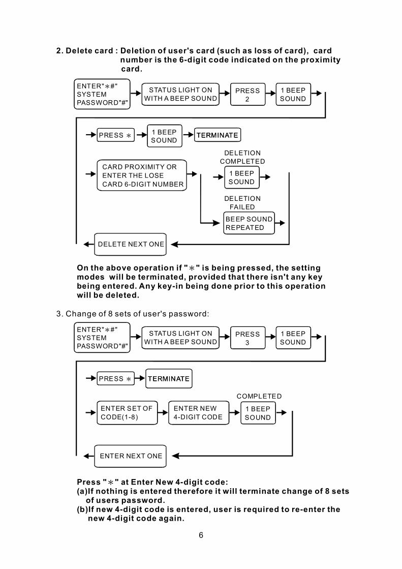
2. Delete card : Deletion of user's card (such as loss of card), card number is the 6digit code indicated on the proximity card.
ENTER" #" SYSTEM PASSWORD"#"
*
ENTER" #" SYSTEM PASSWORD"#"
*
STATUS LIGHT ON WITH A BEEP SOUND
STATUS LIGHT ON WITH A BEEP SOUND
PRESS 2
PRESS 3
PRESS *
PRESS *
CARD PROXIMITY OR ENTER THE LOSE CARD 6DIGIT NUMBER
ENTER SET OF CODE(18)
ENTER NEW 4DIGIT CODE
TERMINATE
TERMINATE
TERMINATE
TERMINATE
DELETE NEXT ONE
ENTER NEXT ONE
DELETION COMPLETED
COMPLETED
DELETION FAILED
1 BEEP SOUND
1 BEEP SOUND
1 BEEP SOUND
1 BEEP SOUND
1 BEEP SOUND
BEEP SOUND REPEATED
On the above operation if " " is being pressed, the setting modes will be terminated, provided that there isn't any key being entered. Any keyin being done prior to this operation will be deleted.
*
3. Change of 8 sets of user's password:
6
Press " " at Enter New 4digit code: (a)If nothing is entered therefore it will terminate change of 8 sets of users password.
(b)If new 4digit code is entered, user is required to reenter the new 4digit code again.
*
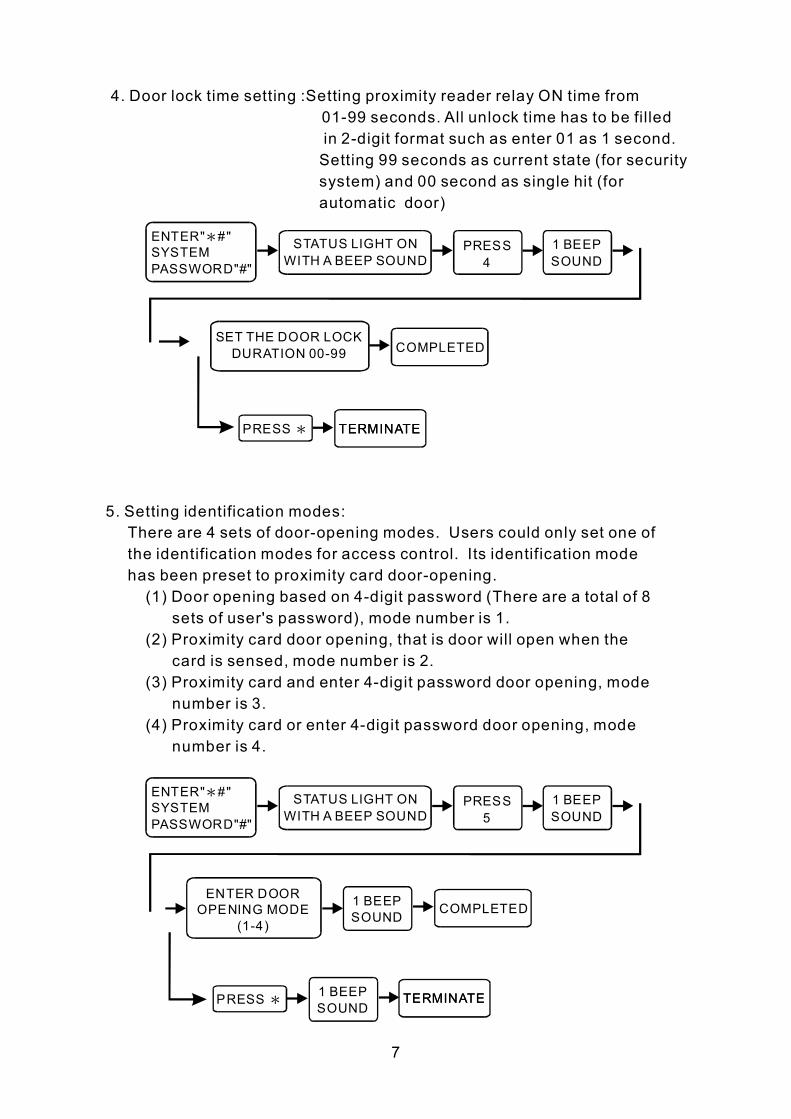
4. Door lock time setting :Setting proximity reader relay ON time from 0199 seconds. All unlock time has to be filled in 2digit format such as enter 01 as 1 second. Setting 99 seconds as current state (for security system) and 00 second as single hit (for automatic door)
ENTER" #" SYSTEM PASSWORD"#"
*
ENTER" #" SYSTEM PASSWORD"#"
*
STATUS LIGHT ON WITH A BEEP SOUND
STATUS LIGHT ON WITH A BEEP SOUND
PRESS 4
PRESS 5
SET THE DOOR LOCK DURATION 0099
ENTER DOOR OPENING MODE
(14)
PRESS *
PRESS *
TERMINATE
TERMINATE
COMPLETED
COMPLETED
TERMINATE
TERMINATE
1 BEEP SOUND
1 BEEP SOUND
1 BEEP SOUND
1 BEEP SOUND
5. Setting identification modes: There are 4 sets of dooropening modes. Users could only set one of the identification modes for access control. Its identification mode has been preset to proximity card dooropening. (1) Door opening based on 4digit password (There are a total of 8
sets of user's password), mode number is 1. (2) Proximity card door opening, that is door will open when the
card is sensed, mode number is 2. (3) Proximity card and enter 4digit password door opening, mode
number is 3. (4) Proximity card or enter 4digit password door opening, mode
number is 4.
7
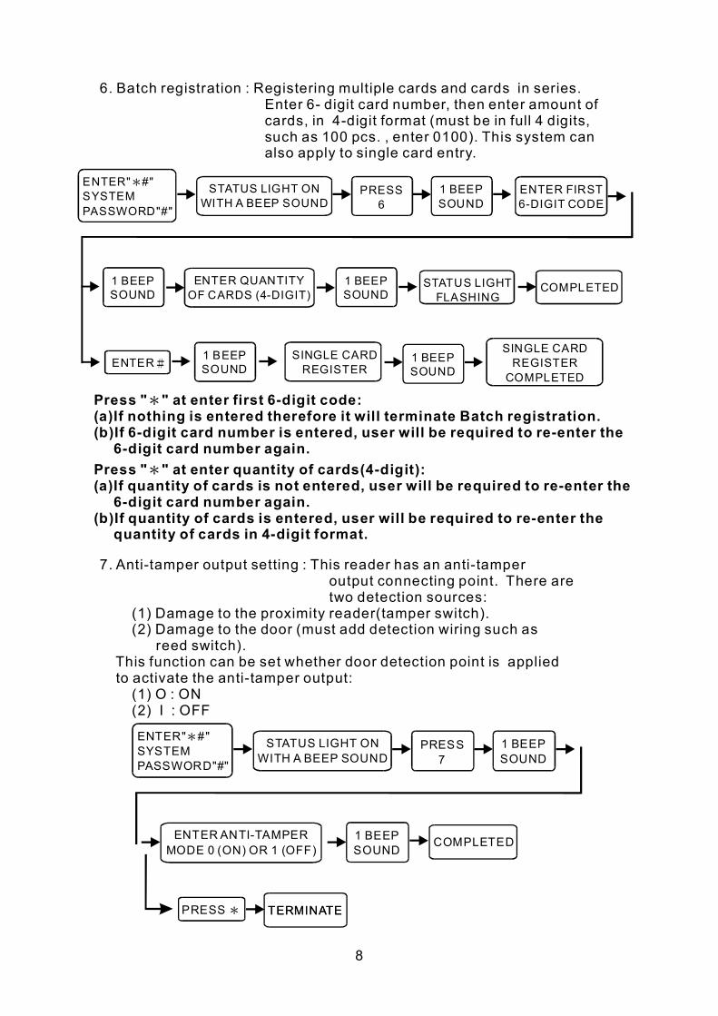
6. Batch registration : Registering multiple cards and cards in series. Enter 6 digit card number, then enter amount of cards, in 4digit format (must be in full 4 digits, such as 100 pcs. , enter 0100). This system can also apply to single card entry.
ENTER" #" SYSTEM PASSWORD"#"
* STATUS LIGHT ON WITH A BEEP SOUND
PRESS 6
ENTER#
COMPLETED STATUS LIGHT FLASHING
1 BEEP SOUND
1 BEEP SOUND
1 BEEP SOUND
1 BEEP SOUND
1 BEEP SOUND
ENTER FIRST 6DIGIT CODE
ENTER QUANTITY OF CARDS (4DIGIT)
SINGLE CARD REGISTER COMPLETED
SINGLE CARD REGISTER
7. Antitamper output setting : This reader has an antitamper output connecting point. There are two detection sources:
(1) Damage to the proximity reader(tamper switch). (2) Damage to the door (must add detection wiring such as
reed switch). This function can be set whether door detection point is applied to activate the antitamper output: (1) O : ON (2) I : OFF
ENTER" #" SYSTEM PASSWORD"#"
* STATUS LIGHT ON WITH A BEEP SOUND
PRESS 7
ENTER ANTITAMPER MODE 0 (ON) OR 1 (OFF)
PRESS * TERMINATE
COMPLETED
TERMINATE
1 BEEP SOUND
1 BEEP SOUND
8
Press " " at enter first 6digit code: (a)If nothing is entered therefore it will terminate Batch registration. (b)If 6digit card number is entered, user will be required to reenter the
6digit card number again.
*
Press " " at enter quantity of cards(4digit): (a)If quantity of cards is not entered, user will be required to reenter the
6digit card number again. (b)If quantity of cards is entered, user will be required to reenter the
quantity of cards in 4digit format.
*
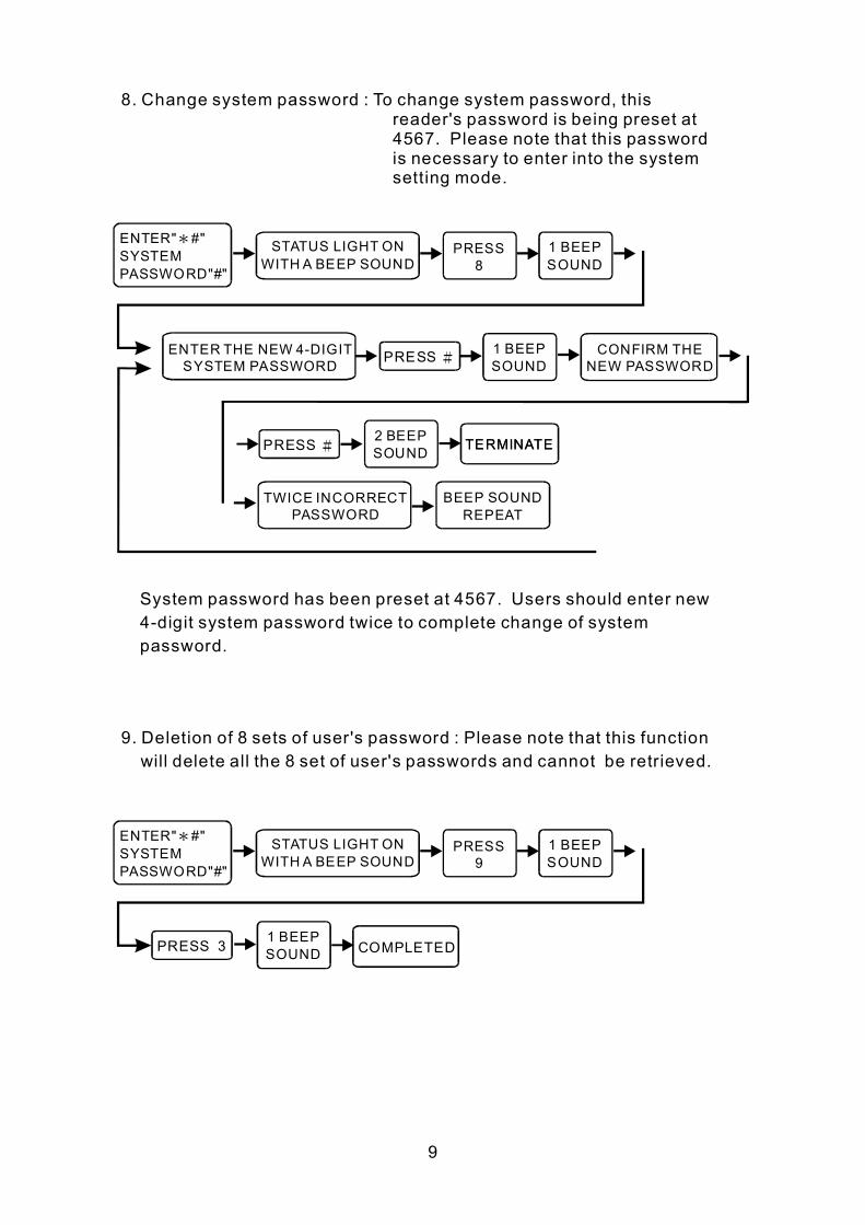
8. Change system password : To change system password, this reader's password is being preset at 4567. Please note that this password is necessary to enter into the system setting mode.
ENTER" #" SYSTEM PASSWORD"#"
*
ENTER" #" SYSTEM PASSWORD"#"
*
STATUS LIGHT ON WITH A BEEP SOUND
STATUS LIGHT ON WITH A BEEP SOUND
PRESS 8
PRESS 9
1 BEEP SOUND
1 BEEP SOUND
2 BEEP SOUND
TWICE INCORRECT PASSWORD
BEEP SOUND REPEAT
1 BEEP SOUND
1 BEEP SOUND
CONFIRM THE NEW PASSWORD
ENTER THE NEW 4DIGIT SYSTEM PASSWORD PRESS #
PRESS 3
PRESS # TERMINATE TERMINATE
System password has been preset at 4567. Users should enter new 4digit system password twice to complete change of system password.
9. Deletion of 8 sets of user's password : Please note that this function will delete all the 8 set of user's passwords and cannot be retrieved.
COMPLETED
9
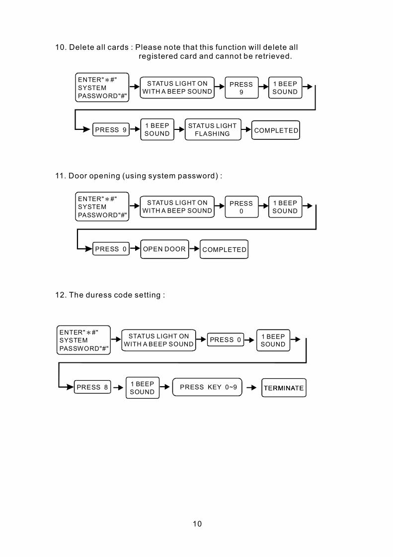
10. Delete all cards : Please note that this function will delete all registered card and cannot be retrieved.
ENTER" #" SYSTEM PASSWORD"#"
*
ENTER" #" SYSTEM PASSWORD"#"
*
ENTER" #" SYSTEM PASSWORD"#"
*
STATUS LIGHT ON WITH A BEEP SOUND
STATUS LIGHT ON WITH A BEEP SOUND
STATUS LIGHT ON WITH A BEEP SOUND
PRESS 9
PRESS 0
1 BEEP SOUND
1 BEEP SOUND
1 BEEP SOUND
1 BEEP SOUND
1 BEEP SOUND
STATUS LIGHT FLASHING PRESS 9
PRESS 0
PRESS 8 PRESS KEY 0~9
PRESS 0
OPEN DOOR
COMPLETED
COMPLETED
11. Door opening (using system password) :
12. The duress code setting :
TERMINATE TERMINATE
10
Ⅴ.INSTALLATION OF PROXIMITY READER :
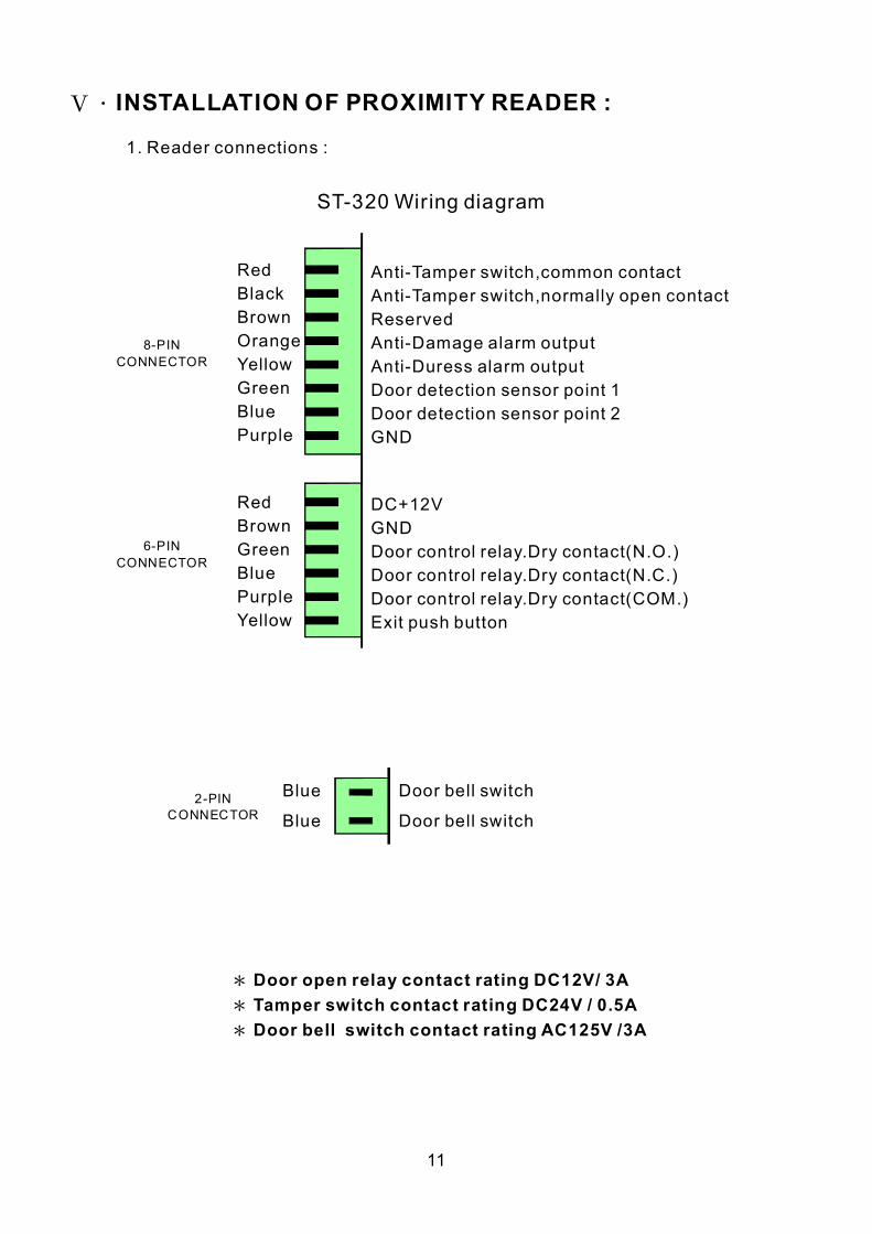
1. Reader connections :
ST320 Wiring diagram
Red Black Brown Orange Yellow Green Blue Purple
Red Brown Green Blue Purple Yellow
AntiTamper switch,common contact AntiTamper switch,normally open contact Reserved AntiDamage alarm output AntiDuress alarm output Door detection sensor point 1 Door detection sensor point 2 GND
DC+12V GND Door control relay.Dry contact(N.O.) Door control relay.Dry contact(N.C.) Door control relay.Dry contact(COM.) Exit push button
8PIN CONNECTOR
6PIN CONNECTOR
2PIN CONNECTOR
Blue
Blue
Door bell switch
Door bell switch
*
*
*
Door open relay contact rating DC12V/ 3A Tamper switch contact rating DC24V / 0.5A Door bell switch contact rating AC125V /3A
11
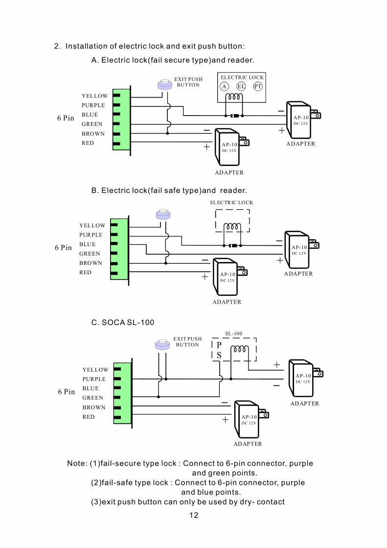
2. Installation of electric lock and exit push button:
Note: (1)failsecure type lock : Connect to 6pin connector, and green points.
(2)failsafe type lock : Connect to 6pin connector, purple and points.
(3)exit push button can only be used by dry contact
purple
blue
12
A. Electric lock(fail secure type)and reader.
B. Electric lock(fail safe type)and reader.
C. SOCA SL100
AP10 DC 12V
AP10 DC 12V
ELECTRIC LOCK
A EL PT EXIT PUSH BUTTON
+ +
YELLOW PURPLE BLUE GREEN
BROWN RED ADAPTER
ADAPTER
6 Pin
YELLOW PURPLE BLUE GREEN BROWN RED ADAPTER
ADAPTER
6 Pin AP10 DC 12V
AP10 DC 12V
+ +
ELECTRIC LOCK
EXIT PUSH BUTTON
ADAPTER
ADAPTER
SL100
AP10 DC 12V
AP10 DC 12V
+
+
P S
YELLOW PURPLE BLUE GREEN
BROWN RED
6 Pin
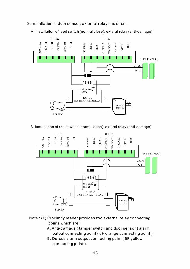
3. Installation of door sensor, external relay and siren :
Note : (1) Proximity reader provides two external relay connecting points which are : A. Antidamage ( tamper switch and door sensor ) alarm
output connecting point ( 8P orange connecting point ). B. Duress alarm output connecting point ( 8P yellow
connecting point ).
13
SIREN
SIREN
REED (N.C)
N.C
COM
N.C N.O
COM
AP10 DC 12V
DC12V EXTERNAL RELAY
DC12V EXTERNAL RELAY
+ +
A. Installation of reed switch (normal close), exteral rslay (antidamage)
B. Installation of reed switch (normal open), exteral rslay (antidamage)
6 Pin
6 Pin
8 Pin
8 Pin
REED(N.O)
N.O
COM
N.C N.O
COM
AP10 DC 12V
+ +
(2) If door sensor detecting (such as reed switch) points are applied, please set ALARM to ON mode. For setting method, please refer to setting mode functional selection item 7 in the manual.
3. For installation, please link power supply wire and control wire through the base panel first and then fix the base panel onto the wall.
4. Install the proximity reader on the base panel (power supply wire and control wire must first be inserted and the wires must be arranged correctly), and then use the enclosed key wrench and screws to mount it up.
5. Power supply: DC 12V 500~800mA.
6. Power consumption, standby 90mA, active 110mA.
7. Dimensions: 125mm (L) X 33mm (W) X 70mm (H).
* DO NOT SHARE THE SAME POWER SUPPLY OF BOTH ELECTRIC LOCK AND PROXIMITY READER TOGETHER. USERS SHOULD PROVIDE SEPARATE POWER SUPPLY FOR BOTH OF THEM.
Ⅵ.PRECAUTIONS :
1. Before installation, please check the voltage and polarity of the power supply in order to avoid wrong connection causing damage to the reader.
2. Please do not share the power supply together with the electric lock and the proximity reader .
3. Please do not install metal product or monitor near this equipment in order to avoid distance proximity.
4. Please do not conduct any fixing or modification to the system, unless by qualified personnel.
5. Warranty period for the reader is 1 year.
14
Ⅶ.TROUBLESHOOTING
1. Card sensed but the door lock doesn't work.
Solution: (1) Please check if the power supply is on the proximity reader and the electric lock.
(2) If (1) is checked, please check the electric lock power supply and whether the connecting points are correct.
(3) Continuous proximity. Please remove the card from the reader and try again.
(4) Please check whether the door opening mode is correct.
2. System password is entered but cannot enter into various functional selection of the setting mode.
Solution : (1)Incomplete input of system password, please check whether the following format has been entered: #XXXX# (XXXX represents system password), or first
press " " then enter valid system password #XXXX#.
(2)Bad wiring. Please arrange and put all power and control wires at a space behind the panel (recommended) to avoid pressing against the PC board which may cause short circuit or poor connection.
*
* *
3. How to use the duress code setting?
Solution : (1) Users should change door opening mode to 4digit password door opening(mode code 1), or proximity card or 4digit password door opening(mode code 4) in order to enable duress code setting.
(2) After the door opening mode is set(please refer to item 5 of the setting mode functional selection on how to set door opening mode),press" The Duress code+4digits door opening password ",then the duress alarm output function will execute.
*# #
4. How to terminate antidamage activation or duress alarm activity?
Solution : Enter into system setting mode or open the door.
5. What is the operation of the door sensor detection (reed switch)?
Solution : If the door sensor detection function is being set at ON (for detail, refer to item 7 of the setting mode functional selection in the manual) and if the door is not closed within 30 seconds, then the antidamage output function will be activated.
15
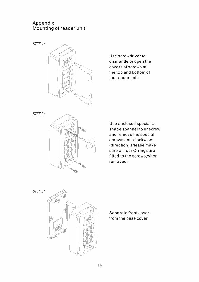
Appendix Mounting of reader unit:
STEP1:
STEP2:
STEP3:
Use screwdriver to dismantle or open the covers of screws at the top and bottom of the reader unit.
Use enclosed special L shape spanner to unscrew and remove the special acrews anticlockwise (direction).Please make sure all four Orings are fitted to the screws,when removed.
Separate front cover from the base cover.
16
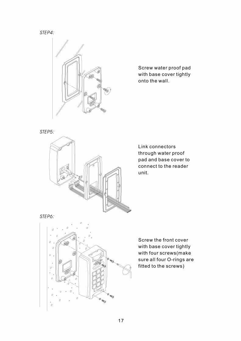
STEP4:
STEP5:
STEP6:
Screw water proof pad with base cover tightly onto the wall.
Link connectors through water proof pad and base cover to connect to the reader unit.
Screw the front cover with base cover tightly with four screws(make sure all four Orings are fitted to the screws)
17
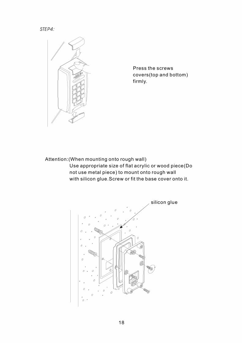
STEP4:
Press the screws covers(top and bottom) firmly.
Attention:(When mounting onto rough wall) Use appropriate size of flat acrylic or wood piece(Do not use metal piece) to mount onto rough wall with silicon glue.Screw or fit the base cover onto it.
silicon glue
18
Recommended