Embed Size (px)
Citation preview

1
Rada 320Installation and Maintenance
Water Temperature ControlsGroups of Fixtures
Thermostatic
This Rada 320 Valve has been supplied for this application based upon information provided to Armstrong at the time the order was placed.
This Rada 320 Valve is configured for use in a “dead-leg” piping configuration as indicated in the drawing on Page 5.
This Rada 320 Valve has not been configured for use in a central pumped re-circulation system.
This Rada 320 Valve has not been designed to deliver tepid water to Emergency Fixtures.
For further information, please call our technical department Toll Free at 1-888-HOT-HOSE.
Model No. Rada 320 Rada 320D Rada 320DC
Serial No.
Ship Date
1017
ALIB-320-C
B125

2
Water Temperature Control - Groups of Fixtures
ThermostaticRada 320Rada Thermostatic Mixing Valve of “sealed for life” disposable cartridge construction. Compact design with top and/or bottom blended water outlet makes Rada 320 ideal for recessed enclosure, plumbing chase and utility/mechanical room installation.
Complete operating mechanism of valve is enclosed in a durable polymer cartridge for ease of field maintenance. Powerful internal mechanism and non metallic wetted parts resist mineral deposition.
Capable of close temperature control at diverse flow rates between 1 gpm (3.8 lpm) 24 gpm (91 lpm). Able to blend within 5°F (2°C) of either inlet supply due to “low seepage” across internal proportioning mechanism.
Operational Specifications• Dualthermostaticelementsprovideredundancyinthe
event of individual thermostat failure• Typicaloutlettemperaturecontrol+/-2°F• Adjustablemaximumtemperaturelimitstop• Adjustablesingletemperaturelockout• Thermalshutdownmodeuponinletsupplyfailure
Technical Specifications• 1” NPT inlets and 1” NPT outlet• Chrome-platedDZRbrass/polymerconstruction• Operating pressures
Maximum: 150 psi (10 bar) Minimum: 10 psi (.7 bar)• Integral inlet check valves and strainers• ASSE 1017 and CSA B125 certified• Shipping weight 10 lbs (4.5 kg)
Forasubmittaldrawing,refertoCDLW#1061.
BlendedWater
3"(77 mm)4x Ø 5/32"
on 1.75 DBC
ColdWater
HotWater
5-7/8"(149 mm)
2"(52 mm)
7-3/8"(187 mm)
Ø 3-1/4"(83 mm)
Rada Thermostatic Mixing Valves (gpm)
ModelPressure Drop (psi) Min.
FlowCV5 10 15 20 25 30 35 40 45 50
320 8 11 13 15 17 19 20 22 23 24 1 3.4
425 15 22 27 31 35 38 41 44 46 49 2 6.9
40 36 51 62 72 - - - - - - 2 16.0
50 49 70 85 98 - - - - - - 2 22.0

3
Water Temperature Control - Groups of Fixtures
ThermostaticRada 320DA derivative assembly of the standard Rada 320 Thermostatic Mixing Valve of “sealed for life” disposable cartridge construction. Compact design with top and/or bottom blended water outlet makesRada320Didealforrecessedenclosure,plumbingchaseand utility/mechanical room installation.
Complete operating mechanism of valve is enclosed in durable polymer cartridge for ease of field maintenance. Powerful internal mechanism and non metallic wetted parts resist mineral deposition.
Capable of close temperature control at diverse flow rates between 1 gpm (3.8 lpm) and 24 gpm (91 lpm). Able to blend within 5°F (2°C) of either inlet supply due to “low seepage” across internal proportioning mechanism.
Operational Specifications• Dualthermostaticelementsprovideredundancyinthe
event of individual thermostat failure • Typicaloutlettemperaturecontrol+/-2°F• Adjustablemaximumtemperaturelimitstop• Adjustablesingletemperaturelockout• Thermalshutdownmodeuponinletsupplyfailure
Technical Specifications • 3/4” NPT inlets and 3/4” NPT outlet• Chrome-platedDZRbrass/polymerconstructionwith self-finishbrassandbronzecomponents(320D)or withnickel-platedcomponents(320DC)
• Operating pressures Maximum: 150 psi (10 bar) Minimum: 10 psi (.7 bar)• Integral combination inlet check stop/union/strainers• Outlet thermometer and outlet flow control valve• ASSE 1017 and CSA B125 certified• Shipping weight 10 lbs (4.5 kg)
Forasubmittaldrawing,refertoCDLW#1102. 7-3/8"(187 mm)
9-1/8"(232 mm)
11-7/16"(291 mm)
Rada 320
Rada Thermostatic Mixing Valves (gpm)
ModelPressure Drop (psi) Min.
FlowCV5 10 15 20 25 30 35 40 45 50
320 8 11 13 15 17 19 20 22 23 24 1 3.4
425 15 22 27 31 35 38 41 44 46 49 2 6.9
40 36 51 62 72 - - - - - - 2 16.0
50 49 70 85 98 - - - - - - 2 22.0
4
Safety Warnings
The function of a Thermostatic Mixing Valve is to deliver water consistently at a pre-designated temperature.
Rada Thermostatic Mixing Valves are precision engineered to give continued superior and safe performance provided:
1. They are installed, commissioned, operated and maintained in accordance with the recommendations provided and accepted plumbing practices.
2. Periodic attention is given, as necessary, to maintain the product, the accessory fittings and the plumbing system in good functional order.
In keeping with every other mechanical product, Rada Mixing Valves should not be considered as functionally infallible and, as such will never totally replace the vigilance and attention of facility nursing/bathing or other institutional supervisory or industrial safety staff.
Provided that they are installed, commissioned, operated and maintained, the risk of product failure and its associated consequences, if not eliminated, are reduced to the minimum achievable.
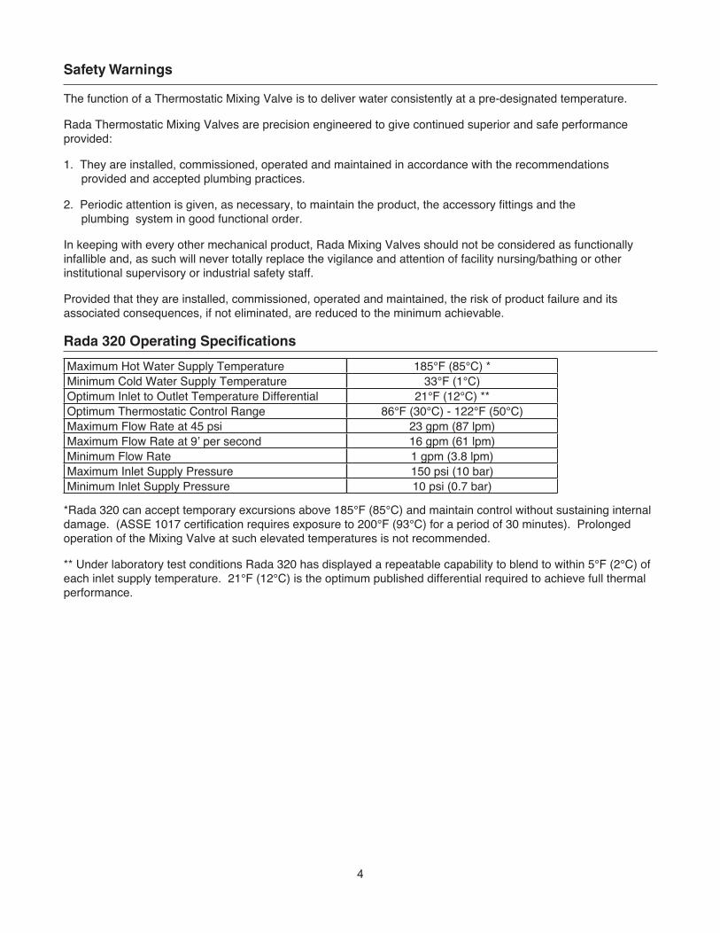
Rada 320 Operating Specifications
*Rada 320 can accept temporary excursions above 185°F (85°C) and maintain control without sustaining internal damage. (ASSE 1017 certification requires exposure to 200°F (93°C) for a period of 30 minutes). Prolonged operation of the Mixing Valve at such elevated temperatures is not recommended.
** Under laboratory test conditions Rada 320 has displayed a repeatable capability to blend to within 5°F (2°C) of each inlet supply temperature. 21°F (12°C) is the optimum published differential required to achieve full thermal performance.
Maximum Hot Water Supply Temperature 185°F (85°C) *Minimum Cold Water Supply Temperature 33°F (1°C) Optimum Inlet to Outlet Temperature Differential 21°F (12°C) **Optimum Thermostatic Control Range 86°F (30°C) - 122°F (50°C)Maximum Flow Rate at 45 psi 23 gpm (87 lpm)Maximum Flow Rate at 9’ per second 16 gpm (61 lpm)Minimum Flow Rate 1 gpm (3.8 lpm)Maximum Inlet Supply Pressure 150 psi (10 bar)Minimum Inlet Supply Pressure 10 psi (0.7 bar)

5
The Rada 320 Thermostatic Mixing Valve must be installed as per the piping schematic provided on Page 5. Failure to follow this directive will compromise valve/system performance, void all warranties and may create a user comfort issue and safety concern.
Armstrong has Rada technical support personnel available from 8:00 a.m. to 5:00 p.m. EST. Call Toll Free 1-888-HOT HOSE.
Notes:1. Rada 320 may be installed in a vertical or horizontal position.
2. Rada 320 must be installed in a standard HOT-LEFT/COLD-RIGHT inlet supply configuration. There are red(hot) and blue(cold) markings on each valve. Rada 320 is provided as standard with a piped top outlet and a plugged bottom outlet. This configuration can be reversed by simply switching the outlet plug and fittings. The inlet supplies must always match the corresponding inlet ports on the valve. Rada 320D/DC is provided as standard with a top outlet which can also be reversed.
3. Install flat faced union connections* at each inlet and the outlet as close to the mixing valve as feasible to facilitate check valve and inlet strainer screen service and replacement.
4. Be sure to thoroughly flush the pipework before fitting the Rada 320.
5. Be sure to “make up” all “sweat” or “soldered” fittings ahead of time. Do not expose Rada 320 or any of its fittings to extreme temperatures (such as an acetylene or propane torch).
6. Rada 320 is serviced from the front of the valve as you face it. A minimum 18” clearance in front of the Temperature Control Handle is suggested for internal parts access.
7. Rada 320 is pre-set at the factory to a fixed outlet temperature of 110°F (43°C). It is highly unlikely that the installation site conditions will match the test conditions. As such:
RADA 320 MUST BE RE-SET ON SITE BY QUALIFIED PERSONNEL.Rada 320 set up (commissioning the Rada 320 and the system) protocol is included on Page 6.
Rada 320 Installation
Rada 320 Piping Schematic
Rada 215,320 (shown)or 425 TMV
Cold Water Supply
Hot Water Supply
Mix
ed F
low
- Legend -System Layout
Strainer
Stop Valve
Isolation Valve
Check Valve
Shower
Sink
Thermometer
* Factory supplied on Rada 320D/DC and when Rada 320 is installed in a cabinet assembly (320 FMC/SMC).

6
Commissioning must be carried out in accordance with these instructions, and must be conducted by designated, qualified and competent personnel.
Ensure that the hot and cold supplies are at their designated pressures and temperatures. Open mixed water outlet(s) and wait until the hot and cold inlet temperatures are stable. Note the mixed water temperature.
If the mixed water temperature requires adjustment, turn the temperature control handle clockwise to reduce the temperature or counterclockwise to increase it. Allow a few seconds for the temperature to stabilize.
If the blend temperature required is not obtainable (not hot enough) it is likely that the mixing valve has reached the factory calibrated maximum temperature set point. To recalibrate set point see Maximum Temperature below.
Maximum Temperature. The maximum blend temperature obtainable through the mixing valve should be limited to prevent selection of a system temperature that is too hot.
Rada 320 is fully performance tested and the maximum temperature is pre-set to approximately 110°F (43°C) under ideal installation conditions at the factory.
Site conditions and design preference may dictate that the maximum temperature has to be re-set following installation.
Maximum Temperature SettingCheck that an adequate supply of hot water is available at the hot inlet of the mixing valve.
For optimum performance the minimum temperature of the hot water must be at least 21°F (12°C) above the desired blend, however during resetting this should be close to the typical storage maximum to reduce the possibility of any blend shift due to fluctuating supply temperatures.
Temperatures should always be recorded using a thermometer with proven accuracy.
For Adjustable Temperature1. Remove the temperature knob screw using a 3 mm hexagonal wrench (supplied). Remove the temperature
knob.
2. Pull off the black polymer hub assembly which may inadvertently remain attached to the inside of the temperature control handle. This is a “push fit” and can be “levered” out using a thin blade screwdriver or pliers.
3. Rotate the spindle until required maximum blend temperature is obtained at outlet point (clockwise = decrease temperature, counterclockwise = increase temperature). When resistance is felt do not use force to turn any further, as this can damage the internal parts.
4. Once the desired maximum blend temperature is achieved, re-fit the hub without disturbing the spindle: Position the hub so that the hub stop comes up against the cartridge stop (refer to Figure 7-1) preventing any further rotation in a counterclockwise direction. Check that blend temperature has not altered.
5. Refit the temperature knob. Make sure that the indicator points to 9 o’clock.
Commissioning the Rada 320

7
For Locked Temperature1. Remove the temperature knob using a 3 mm hexagonal wrench (supplied).
2. Pull off the black polymer hub assembly which may inadvertently remain attached to the inside of the temperature control handle. This is a “push fit” and can be “levered” out using a thin blade screwdriver or pliers.
3. Rotate the spindle until required maximum blend temperature is obtained at outlet point (clockwise = decrease temperature, counterclockwise = increase temperature).
When resistance is felt do not use force to turn any further, as this can damage the internal parts.
4. Once the desired maximum blend temperature is achieved, re-fit the hub without disturbing the spindle, positioning it so that the center stop slot in the hub fits over the top of the cartridge stop (refer to Figure 7-1), preventing any further rotation in either direction. Check that the blend temperature has not altered.
5. Refit the temperature knob. Make sure that the indicator points to 6 o’clock.
Rada 320 Servicing and Maintenance (Refer to Figures 8-1 and 8-2)
Rada 320 Thermostatic Mixing Valves should be inspected annually, or more frequently where acknowledged site conditions such as high mineral content water dictate.
It is highly recommended that as a function of the annual inspection that the two “racetrack” shaped o-seals within the valve are replaced (D33387) seal pack.
Rada 320 Thermostatic Mixing Valve is of non-serviceable single “cartridge construction”. The cartridge can be removed from the valve for inspection or replacement by first removing the chromed brass temperature control handle using a 3 mm hex wrench. The black polymer hub assembly may inadvertently remain attached to the inside of the temperature control handle. This is a “push fit” and can be “levered” out using a thin blade screwdriver or pliers.
The chromed polymer Temperature Indicator Ring, which fits beneath the temperature control handle can be “levered” off using a thin edged tool such as a razor blade knife.
Before proceeding further be sure to isolate the valve by turning off each inlet supply.
The complete cartridge assembly is accessed by first removing the 6 Phillips head-retaining screws and then smoothly drawing the cartridge out. Do not twist or apply “side load” leverage when extracting the cartridge.
When installing a new or reinstalling an existing cartridge note the raised “H” on the hot inlet of the cartridge and align to hot supply accordingly. Conversly, align raised “C” with cold supply.
Commissioning the Rada 320
Figure 7-1

8
The Rada 320 Mixing Unit features a single “sealed for life” disposable internal cartridge. With an allen key (3 mm) to remove the handle retaining screw and a phillips head screwdriver to remove the 6 cartridge retaining screws, the entire mixing unit can be serviced and/or replaced in approximately 10 minutes.
Note: All seals are pre-lubricated. If further lubrication is required, use only silicone based lubricants on this product. Do not use petroleum based lubricants.
Step 1 Step 2
Step 3
Figure 8-2
Body
Cartridge Guides
Temperature Spindle
Temperature Indicating Ring
Temperature Knob
Screw
3 mm Hexagon Wrench
Hub
Screw
Cartridge Cut-out To Aid Removal
Cartridge Assembly
‘H’ and ‘C’ marked on cartridge. Make sure that the ‘H’ is lined up with the hot inlet and that the ‘C’ is lined up with the cold inlet
Figure 8-1Cartridge Assembly Removal
9
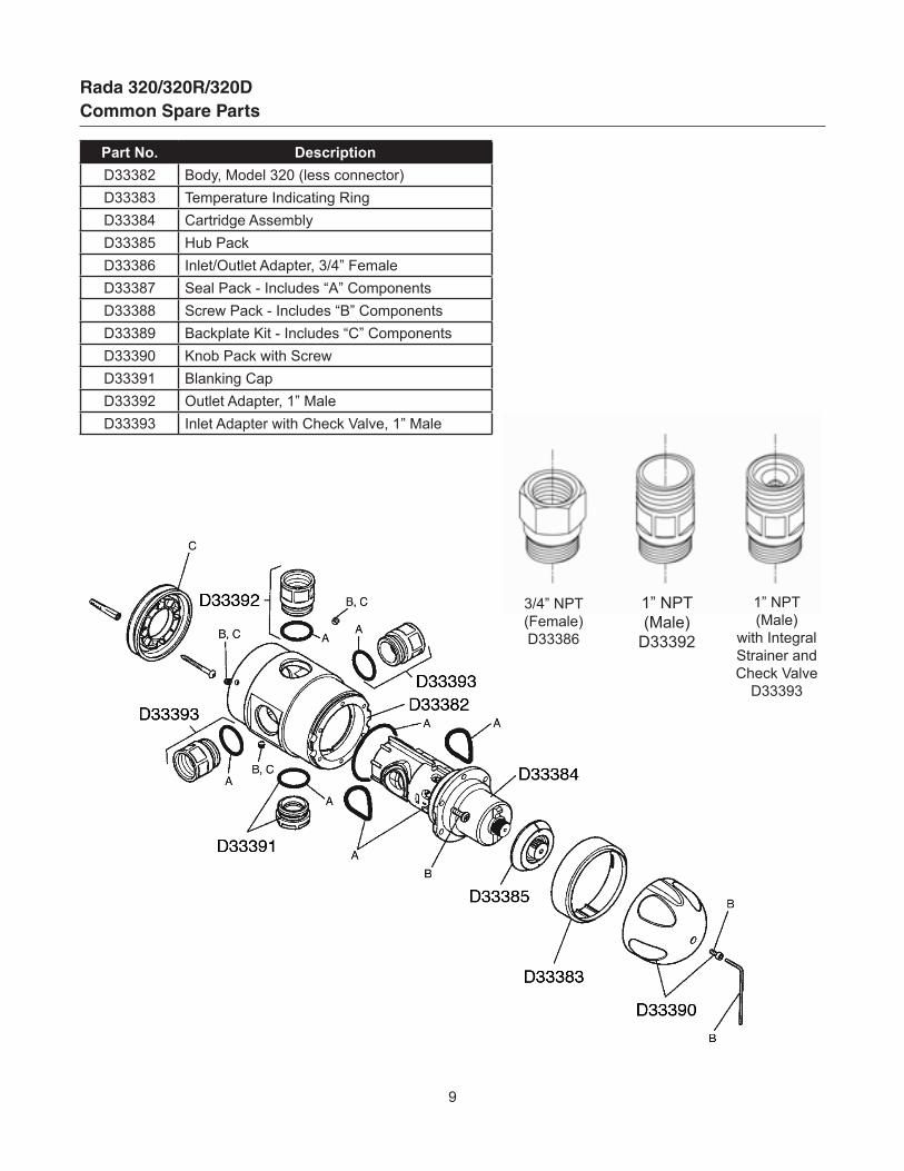
Rada 320/320R/320DCommon Spare Parts
Part No. DescriptionD33382 Body, Model 320 (less connector)D33383 Temperature Indicating RingD33384 Cartridge AssemblyD33385 Hub PackD33386 Inlet/Outlet Adapter, 3/4” FemaleD33387 SealPack-Includes“A”ComponentsD33388 ScrewPack-Includes“B”ComponentsD33389 BackplateKit-Includes“C”ComponentsD33390 Knob Pack with ScrewD33391 Blanking CapD33392 Outlet Adapter, 1” MaleD33393 Inlet Adapter with Check Valve, 1” Male
3/4” NPT(Female)D33386
1” NPT(Male)D33392
1” NPT(Male)
with Integral Strainer andCheck ValveD33393

10
Fault Diagnosis
Symptom Cause Action
1. Only hot or cold water from outlet.
a. Inlet supplies reversed (i.e.: hot to cold or vice-versa)
Check-Rectify. Tip: check rear of valve under polymer mounting plate for raised “H” (hot)on appropriate inlet. If sight evaluation is not possible consult factory Technical Support for additional diagnositc tips.
Check-rectifyb. No hot water available from hot water source.
Check-Rectifyc. Screen/filters occluded or inlet supply fittings plugged.
d. Refer to Symptom 4 below. Refer to Symptom 4 below.
e. Proportioning mechanism (shuttle) trapped against hot/cold seat.
Refer to Servicing/Maintenance on Pages 7-8. and Fig. 8-1. Inspect-Rectify-Replace.
2. No flow from Mixing Valve outlet.
a. Hot or Cold inlet supply failure; Thermostat holding correct shutdown function. Check-Rectify.
b. Screens/filters blocked or inlet supply fittings plugged. Check-Rectify.
3. Mixed water temperature at TMV outlet fluctuates and does not respond to adjustment.
a. Thermostat not operating correctly. Replace cartridge D33384.
b. Mixing Valve operating below minimum required flow rate. Check that at least 1 GPM is flowing through valve.
c. Static inlet supply pressures beyond valves capability to correct. Check-Rectify
d. Inlet supply pressures fluctuating beyond valves capability to correct. Check-Rectify
e. Hot water supply temperature fluctuating beyond valves capability to correct.
Check by carefully sensing inlet hot supply pipe work- rectify.
f. Partially occluded screens/filters or partially blocked inlet fittings. Check-Rectify.
4. Hot water in cold supply and vice-versa.
a. Indicates non-functioning check valve (s).Diagnose by turning off mixed water outlet flow and check to see if inlet hot pipe work becomes cold and vice-versa.
5. Mixed water temperature too high.
a. Mixing Valve has not been commissioned correctly and set too high. Refer to Commissioning on Page 6 - Rectify.
b. Mixing Valve has not been commissioned correctly and was set when the hot supply temperature was too low.
Refer to Commissioning on Page 6 - Rectify.
c. Hot water is migrating into cold supply. See Item 4 above.
d. Thermostat not operating correctly. Replace cartridge D33384.
6. Mixed water temperature too low.
a. Mixing Valve has not been commissioned correctly and is set too low. Refer to Commissioning on Page 6 - Rectify.
b. Hot water heat is not keeping up with demand. Check-Rectify.
7. Mixed water flow rate is reduced.
a. Partially occluded inlet screens/filters or partially blocked inlet fittings. Check-Rectify.
b. Inlet supply pressure has fallen. Check-Rectify.
c. Accumulated pressure losses within the system are too high.
Refer to a trained and appropriate authority for system sizing assistance.
8. Water leaking from valve body. a. Seals worn or damaged. Obtain Seal Pack D33387.

11
Notes

12
Limited Warranty and RemedyArmstrongHotWaterGroup,Inc.(“Armstrong”)warrantstotheoriginaluserofthoseproductssuppliedbyitandused in the service and in the manner for which they are intended, that such products shall be free from defects in material and workmanship for a period of one (1) year from the date of installation, but not longer than 15 months fromthedateofshipmentfromthefactory[unlessaSpecialWarrantyPeriodapplies,aslistedbelow].Thiswarrantydoesnotextendtoanyproductthathasbeensubjecttomisuse,neglect,oralterationaftershipmentfrom the Armstrong factory. Except as may be expressly provided in a written agreement between Armstrong and the user, which is signed by both parties, Armstrong DOES NOT MAKE ANY OTHER REPRESENTATIONS OR WARRANTIES, EXPRESS OR IMPLIED, INCLUDING, BUT NOT LIMITED TO, ANY IMPLIED WARRANTY OF MERCHANTABILITY OR ANY IMPLIED WARRANTY OF FITNESS FOR A PARTICULAR PURPOSE. The sole and exclusive remedy with respect to the above limited warranty or with respect to any other claim relating to the products or to defects or any condition or use of the products supplied by Armstrong, however caused, and whether such claim is based upon warranty, contract, negligence, strict liability, or any other basis or theory, is limited to Armstrong’s repair or replacement of the part or product, excluding any labor or any other cost to remove or install said part or product, or, at Armstrong’s option, to repayment of the purchase price. As a condition of enforcing any rights or remedies relating to Armstrong products, notice of any warranty or other claim relating to the products must be given in writing to Armstrong: (i) within 30 days of last day of the applicable warranty period, or (ii) within 30 days of the date of the manifestation of the condition or occurrence giving rise to the claim, whichever is earlier. IN NO EVENT SHALL ARMSTRONG BE LIABLE FOR SPECIAL, DIRECT, INDIRECT, INCIDENTAL OR CONSEQUENTIAL DAMAGES, INCLUDING, BUT NOT LIMITED TO, LOSS OF USE OR PROFITS OR INTERRUPTION OF BUSINESS.TheLimitedWarrantyandRemedytermshereinapplynotwithstanding any contrary terms in any purchase order or form submitted or issued by any user, purchaser, or thirdpartyandallsuchcontrarytermsshallbedeemedrejectedbyArmstrong.
Armstrong International221 Armstrong Blvd., Three Rivers, Michigan 49093 - USAPh: (269) 279-3602 Toll Free: (888) HOT-HOSE (468-4673) Fax: (269) 279-3130
ALIB-320-CRada 320
Printed in U.S.A. - 5/12© 2012 Armstrong International, Inc.
Designs, materials, weights and performance ratings are approximate and subject to change without notice.Visit armstronginternational.com for up-to-date information.
Special Warranty Periods are as follows:
Flo-Direct Gas Fired Water HeaterThestainlesssteelstructureandstainlesssteelinternals(flame,tube,pallrings,supports,etc.)shallhaveaten(10)yearnon-proratedguaranteeagainstburnoutoranystructuralfailurecausedbymaterials and workmanship. Provided only clean potable water is heated. The other components on the Flo-Direct,suchasvalves,combustionequipment,electricalcontrols,andtheburnershallhaveatwo(2)yearnon-proratedguaranteeagainstfailurecausedbymaterialsandworkmanship.
Flo-Rite-Temp Instantaneous Water HeaterThetubebundleshallhavea10-yearguaranteeagainstfailurecausedbymaterialsorworkmanshipprovided by Armstrong but not against gasket failure or damage caused by corrosion, water hammer or lack of proper cleaning.
Flo-Rite-Temp Packaged Instantaneous Water HeaterTwo (2) years from the date of installation, but not longer than 27 months from the date of shipment. See above for tube bundle guarantee.
Flo-Eco High Efficiency Gas Water HeaterThe heat exchanger and supplied integral components such as the burner, the electrical controls and valving shall have a two (2) year warranty from the date of installation but no longer than 27 months from the date of shipment. The tank and replaceable tank liner shall have a 5 year warranty from the date of shipment.
The Brain – Model DRV80andderivativeassembliesshallhavea5-yearallcomponentpartswarranty.