Approved for public release; NG 10-0623; 5/11/10.
Self-induced Vibration of NGAS Space Pulse Tube Coolers
R. Colbert, T. Nguyen, J. Raab, E. Tward
Northrop Grumman Aerospace Systems
Redondo Beach, CA, 90278
ABSTRACT
Space cryocoolers are often used to cool the focal planes and optics of telescopes. Since
telescope and focal plane jitter can affect the clarity of the image, space cryocoolers are designed
for inherent low vibration. For very sensitive applications, many cryocooler systems incorporate
active vibration control in addition to passive isolation from their mounting structures. The sole
moving parts in all the NGAS pulse tube coolers, whether one, two or three stage, are the moving
compressor pistons and their flexure supports that are inherently balanced in a back to back
configuration. To further reduce the vibration below this already very low level, all the cooler
systems are provided with single axis active control on the drive axis of the compressor that
contains the moving piston masses. The cryocooler control electronics takes a signal from an
accelerometer mounted parallel to the drive axis and feeds it back to the compressor motor drive
signals to further reduce the vibration by >40dB. In this paper we present the self-induced
vibration measurements made on a number of NGAS flight coolers including the single stage
HEC cooler with both linear or coaxial cold heads and a micro cooler. We also present self-
induced vibration measurements for the simultaneous operation of two HEC coolers mounted to
the same platform.
INTRODUCTION
The exported vibration of a pulse tube cooler is caused by the acceleration of the moving
masses in the cooler during its periodic motion. The acceleration comes from three main sources:
1) the reciprocating motion of the pistons, 2) the elastic response of the structures to the
internally oscillating pressure and 3) the dynamic fluid-structure interaction in the cold head.
Pulse tube coolers generate a lower vibration level than linear Stirling coolers because they do
not have the additional vibration resulting from the cold moving displacer. For some
applications, active vibration control may be desirable to further reduce the exported vibration
from their already low levels.
Northrop Grumman (NG) back to back compressor modules inherently cancel most of a
pulse tube cooler’s exported vibration levels to low levels typically in the <200mN range. Since
the motors are driven harmonically in anti-phase at their common resonant frequency that is
fixed in the 30Hz to 120Hz range depending on the cooler, the output vibration signature in the
Approved for public release; NG 10-0623; 5/11/10.
frequency domain consists of a series of spikes at the fundamental drive frequency and its
harmonics. To assure that the moving mass balance is maintained over the typical 10 year
lifetime and to further reduce the vibration along the moving mass axis, all NG coolers use an
accelerometer mounted parallel to the piston motion axis as a feedback source for an error signal
to the drive electronics. The drive electronics takes the error signal from an accelerometer
mounted parallel to the drive axis on the compressor and corrects the drive waveforms to null the
fundamental and 15 harmonics of the drive frequency. Therefore, even the lowest drive
frequency cooler system is capable of active vibration control to a minimum frequency of 500Hz
and the highest frequency coolers to frequencies well above 1000 Hz. This paper presents the
vibration test data collected on Northrop Grumman’s HEC1 and microcoolers
2. Exported
vibration data are presented for different input powers, cooler mounting techniques and the
simultaneous operation of two HEC coolers.
TEST APPARATUS
The exported vibration testing was conducted at Northrop Grumman’s Cryocooler Dynamic Test
Facility. Data was collected in 2 ways. The most common method is to mount the coolers on a
fixture attached to a Kistler 9257B Dynamometer. In this facility the Kistler dynamometer can
measure forces and torques in 3 directions with background noise force magnitudes below a few
mN. The mechanical cooler and dynamometer fixture are mounted on a 2 inch thick steel plate
which is bolted to a 70-ton seismic mass beneath and decoupled from the floor. The test
apparatus design assures that a stable and rigid base is used in the calibrated force measurements.
This gives a direct measure of the force and torque output. However, since the cooler is rigidly
mounted to the massive fixture, the accelerometer output is too small to produce an error signal
output at these very low vibration levels. Therefore the loop is closed around one of the Kistler
force transducers parallel to the cooler drive axis. In this test mode the well understood rigid
boundary condition provides the data that an analyst can use to determine the effect on a more
complex spacecraft structure. The dynamic data are analyzed and processed with a Data Physics’
SignalCalc Dynamic Signal Analyzer. The SignalCalc Analyzer provides highly accurate
measurements in the time, frequency, amplitude, and order domains with the capability of
synchronous data averaging to recover data from the background noise. In the second test mode,
the cooler is suspended while attached to its heat rejection fixture via low frequency “bungee”
cords. In this case, the cooler has a very low frequency boundary condition and the loop can be
closed around the flight accelerometer. Measurements are taken with reference accelerometers
attached to the cooler and fixture and their output is converted to force from knowledge of the
suspended mass. This is the other extreme boundary condition data that analysts can use. In both
the rigid mounting and the suspended mounting the cooler was operated with a purge gas rather
than in vacuum in order to remove the additional fixture modes associated with the vacuum
hardware.
HEC COOLER EXPORTED VIBRATION
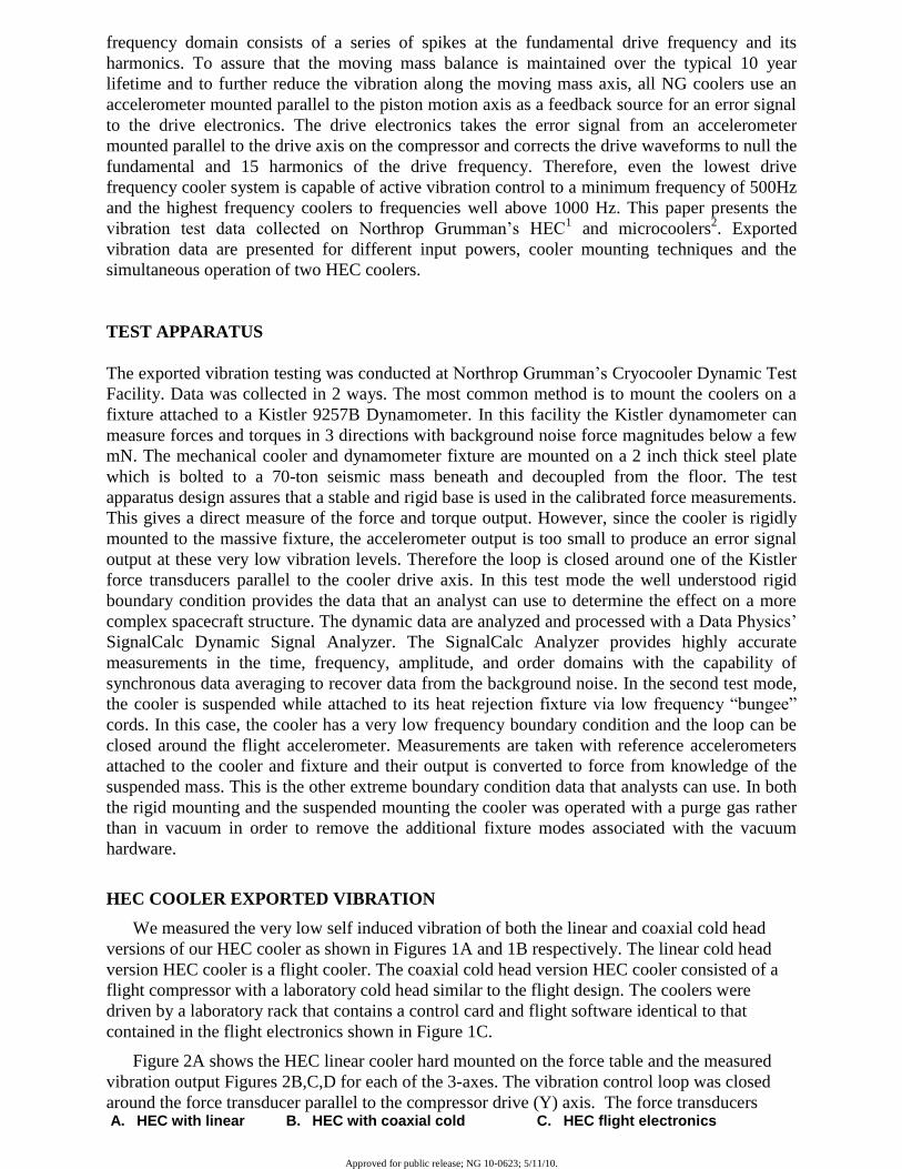
We measured the very low self induced vibration of both the linear and coaxial cold head
versions of our HEC cooler as shown in Figures 1A and 1B respectively. The linear cold head
version HEC cooler is a flight cooler. The coaxial cold head version HEC cooler consisted of a
flight compressor with a laboratory cold head similar to the flight design. The coolers were
driven by a laboratory rack that contains a control card and flight software identical to that
contained in the flight electronics shown in Figure 1C.
Figure 2A shows the HEC linear cooler hard mounted on the force table and the measured
vibration output Figures 2B,C,D for each of the 3-axes. The vibration control loop was closed
around the force transducer parallel to the compressor drive (Y) axis. The force transducers A. HEC with linear B. HEC with coaxial cold C. HEC flight electronics

Approved for public release; NG 10-0623; 5/11/10.
cold head head
Figure 1. HEC coolers and flight electronics
A. Cooler Hard Mounted on Force Table
B. X-Axis (Pulse Tube Axis)
C. Y-Axis (Drive Axis)
D. Z-axis
Figure 2. Vibration output of HEC linear cold head cooler hard mounted to dynamometer
parallel to the drive axis are used for feedback in the vibration cancellation algorithm because in
this configuration the flight accelerometer has no output since nothing is moving. This provides
the vibration output at the one extreme hard mounted boundary condition.
Both the raw data and more instructively the data corrected for the fixture response are
shown on each graph. Along the actively controlled drive axis (Y) the vibration cancellation
system reduces the forces into the few mN range. On the other axes all the harmonics are below
100 mN except for the fundamental along the pulse tube axis that is at 183 mN. These
measurements were taken under steady state conditions in which the power is constant and both
the cooling temperature and reject temperature are constant.
Since a real system has a mount with some unknown compliance we also measured the
output at the second extreme boundary condition of the cooler suspended on bungee cords with
accelerometer
Y-Axis (Drive Axis)
X-Axis (Pulse Tube Axis)
Z-Axis (Vertical Axis)
Power slice
Control slice
Approved for public release; NG 10-0623; 5/11/10.
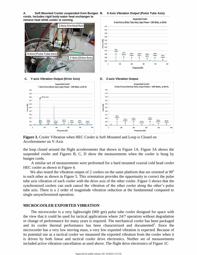
the loop closed around the flight accelerometer that shown in Figure 1A. Figure 3A shows the
suspended cooler and Figures B, C, D show the measurements when the cooler is hung by
bungee cords.
A similar set of measurements were performed for a hard mounted coaxial cold head cooler
HEC cooler as shown in Figure 4.
We also tested the vibration output of 2 coolers on the same platform that are oriented at 90o
to each other as shown in Figure 5. This orientation provides the opportunity to correct the pulse
tube axis vibration of each cooler with the drive axis of the other cooler. Figure 5 shows that the
synchronized coolers can each cancel the vibration of the other cooler along the other’s pulse
tube axis. There is a 2 order of magnitude vibration reduction at the fundamental compared to
single unsynchronized operation.
MICROCOOLER EXPORTED VIBRATION
The microcooler is a very lightweight (900 gm) pulse tube cooler designed for space with
the view that it could be used for tactical applications where 24/7 operation without degradation
or change of performance for many years is required. The mechanical cooler has been packaged
and its cooler thermal performance has been characterized and documented2. Since the
microcooler has a very low moving mass, a very low exported vibration is expected. Because of
its potential use as a tactical cooler we measured the exported vibration from the cooler when it
is driven by both linear and tactical cooler drive electronics. Neither set of measurements
included active vibration cancellation as used above. The flight drive electronics of Figure 1C
A. Soft Mounted Cooler suspended from Bungee cords. Includes rigid body water heat exchanger to remove heat while cooler is running
B. X-Axis Vibration Output (Pulse Tube Axis)
C. Y-axis Vibration Output (Drive Axis)
D. Z-axis Vibration Output
Figure 3. Cooler Vibration when HEC Cooler is Soft Mounted and Loop is Closed on
Accelerometer on Y-Axis
Y-Axis (Drive Axis)X-Axis (Pulse Tube Axis)
Z-Axis (Vertical Axis)
60 Hz noise

Approved for public release; NG 10-0623; 5/11/10.
A. Hard Mounted HEC Coaxial Cooler
B. X-Axis (Pulse Tube Axis)
C. Y-Axis (Compressor Drive Axis)
D. Z-axis
Figure 4. Hard Mounted HEC Coaxial Cold Head Cooler Vibration Uncorrected and Corrected
for Fixture Response
A. HEC Coaxial and HEC Linear Coolers Hard Mounted to Fixture on Force Table
B. X-Axis
C. Y-Axis
D. Z-Axis
Figure 5. 2 Axis vibration cancellation using 2 coolers oriented at 90o
Coax cold head
Linear cold head
X
Y
Y- (Drive Axis)
X- (Pulse Tube Axis)
Z- (Vertical Axis)

Approved for public release; NG 10-0623; 5/11/10.
could be used for flight to reduce the vibration in the drive axis by a further 40dB into the few
mN range if necessary. The cooler and its tactical electronics are shown in Figure 6A. The
vibration output for the 2 different cooler drive techniques are plotted on each graph. The
exported vibration from the tactical drive electronics is higher than the linear drive as expected.
However, the actual values are lower than typical requirements for most space payloads even
without active vibration cancellation. Note that even in the compressor drive direction the
exported vibration is < 0.1N without active control. Further information on the input power
dependence of the exported vibration is given in a companion paper at this conference2.
A. Microcooler with tactical electronics
B. Y-Axis
C. X-Axis
D. Z-Axis
Figure 6. Vibration output of microcooler in 3 axes. No active vibration cancellation is used.
X
Y
Z
Approved for public release; NG 10-0623; 5/11/10.
CONCLUSION
The exported vibration for the HEC coolers with both linear and coaxial cold heads has
been measured. When 2 synchronized coolers are mounted in a 90o orientation to each other, the
exported vibration along each pulse tube axis is further reduced by an order of magnitude. The
exported vibration of the microcooler shows a low exported vibration level in all axes without
active vibration cancellation.
REFERENCES
1. Tward E., et al “High Efficiency Cryocooler” Adv in Cryogenic Engineering, Vol. 47B, Amer.
Institute of Physics, Melville, NY (2002), pp.1077-1084
2. Nguyen, T., Petach M., Michaelian M., Raab J, Tward E., “Space Micro Pulse Tube Cooler”,
Presented at the 16th International Cryocooler Conference, May 17-20, 2010, Atlanta, Georgia
ACKNOWLEDGEMENTS
The work reported in this paper was supported by Northrop Grumman Aerospace System
IR&D funds.
Recommended