P M 25V A R IA B LE D IS P LA C E M E N T P U M PC LO S E D LO O P C IR C U IT
T E C H N I C A L C A T A L O G

2 29/05/2017
PM25 - Variable displacement pump POCLAIN HYDRAULICS
OOVERVIEWPM25 is a variable displacement, axial piston pump, with swashplate system, for closed loop hydrostatic transmissions.
It provides a continuously variable flow rate between zero and maximum in forward and reverse direction. Flow rate is proportional to rotation speed and swashplate angle.
It can feature a charge pump to keep the circuit pressurised. This avoids risk of cavitations and ensures a good performance of the transmission.
It offers several types of control: servo hydraulic, hydraulic automotive, direct or servo mechanical, electrical and electro-proportional.
It is equipped with high pressure relief valves and can be delivered with auxiliary gear pumps.
It is available in single or tandem versions.
As options, PM25 can be featured with flushing valve, filter on charge pressure line and safety devices to ensure safe operation of the machine.
PM25-20 PM25-25 PM25-28
Displacement cm³/rev[in³/rev.]
20,5 [1.25]
25,7 [1.57]
28 [1.71]
Theoretical Flow at rated speed
L/min[GPM]
73,8[19.50]
92,5[24.44]
100,8[26.63]
Rated speed rpm 3 600
Rated pressure bar [PSI] 250 [3 625]
Max. Pressure bar [PSI] 350 [5 076]
Mounting flange SAE B
Controls Hydraulic, hydraulic automotive, direct or servo mechanical, electrical, electro-proportional
Mass kg [lb] from 13 [28.7] to 18 [39.7]
Rotation Clockwise or Counterclockwise
POCLAIN HYDRAULICS Variable displacement pump - PM25
29/05/2017 3
CCONTENT
Syst
em d
esig
n Pa
ram
eter
sM
odel
Cod
eO
pera
ting
Para
met
ers
Tech
nica
l sp
ecifi
catio
nsFe
atur
esO
ptio
nsC
ontr
ols
MODEL CODE 4
TECHNICAL SPECIFICATIONS 6Features 6Main dimensions 7Port characteristics 7
OPERATING PARAMETERS 9Operating parameters 9Charge pressure 9Case pressure 9Pressure ratings 9Speed ratings 9Inlet pressure 10Theoretical output 10Poclain Hydraulics recommandations for fluid 10Fluid and filtration 11Viscosity range 11
SYSTEM DESIGN PARAMETERS 12Sizing equations 12Redundant braking system requirement 12Loop flushing 12Reservoir 13Case drain usage for tandem pump 13Differential pressure 13Bearing life and external shaft loading 14Hydraulic unit life 15Mounting flange loads 15
FEATURES 16High pressure relief valve 16Charge relief valve 17Charge pump 18Displacement limiters 19By-pass 19Mounting flange and shafts 20Auxiliary mounting pad 22Tandem pumps 24Gear pumps 25
CONTROLS 26Direct mechanical control 26Mechanical servo control with feed back 28Hydraulic servo control 30Electrical on-off servo control 32Electrico-proportional servo control 34Hydraulic automotive control 36
OPTIONS 39Roller bearing 39Fluorinated elastomer seals 39UNF threads ports 39Filter on pressure line 40External connections for filter 41Pressure cut-off valve 41Mechanical inching 42Hydraulic inching 42Neutral position switch 43Flushing valve 44Finishing coat 44Customized identification plate 45Anti-stall valve 45

PM25 - Variable displacement pump POCLAIN HYDRAULICS
4 29/05/2017
MMODEL
2 51 2
3ControlDirect mechanical control MMechanical servo control with feed back AHydraulic servo control SHydraulic automotive control 12V D12Hydraulic automotive control 24V D24Electrical on-off servo control with return spring without electrovalve B00Electrical on-off servo control with return spring and electrovalve 12V B12Electrical on-off servo control with return spring and electrovalve 24V B24Electrical on-off servo control without electrovalve C00Electrical on-off servo control with electrovalve 12V C12Electrical on-off servo control with electrovalve 24V C24Electro-proportional servo control 12V P12Electro-proportional servo control 24V P24
4Restrictor mm [in]Without restrictor 00Ø 0,6 [dia. 0.023] 06Ø 0,7 [dia. 0.027] 07Ø 0,8 [dia. 0.031] 08Ø 0,9 [dia. 0.035] 09Ø 1,0 [dia. 0.039] 10Ø 1,2 [dia. 0.047] 12
Restrictors can be assembled for controls typeA, B, C, P, S, D.
1Displacement cm3/rev [in3/rev]20,5 [1.25] 2025,7 [1.57] 2528 [1.71] 28
3 4 5
P M6
2Mounting flange and shaftSAE B; z=13; 16/32 D.P. S3SAE B; z=15; 16/32 D.P. S4SAE B; Key shaft Ø 22,22 mm [dia. 0.87 in] C3Shaft for secondary tandem pump T1
5High pressure relief valve setting Max. system pressure bar [PSI]Without valve (only check valve) 00150 [2 175] 15200 [2 900] 20250 [3 625] 25300 [4 351] 30350 [5 076] 35
6RotationClockwise RCounter clockwise L
MODEL CODE

POCLAIN HYDRAULICS Variable displacement pump - PM25
29/05/2017 5
Syst
em d
esig
n Pa
ram
eter
sM
odel
Cod
eO
pera
ting
Para
met
ers
Tech
nica
l sp
ecifi
catio
nsFe
atur
esO
ptio
nsC
ontr
ols
CCODE
7Charge relief valve setting bar [PSI]Without charge relief valve 0010 [145] (Only for control M) 1022 [319] (For all controls) 22
11107 8 9
8Charge pump displacement cm3/rev [in3/rev]Without charge pump 009,1 [0.55] (For all auxiliary mounting pads) 0812 [0.73] (For auxiliary mounting pad A or S) 12
9Auxiliary mounting padWithout auxiliary mounting pad SGerman group 2 flange GSAE A flange; z = 9 ATandem (without charge pump) T
10Gear pump cm3/rev [cu.in/rev]Without gear pump 00
German group 2 flange (if digit 9 = G)
4,0 [0.24] 046,0 [0.37] 068,5 [0.52] 0811,0 [0.67] 1114,0 [0.85] 1416,5 [1.00] 1719,5 [1.19] 20
SAE A flange (if digit 9 = A)
4,0 [0.24] 046,0 [0.37] 068,5 [0.52] 0811,0 [0.67] 1114,0 [0.85] 1416,5 [1.00] 1719,5 [1.19] 2022,5 [1.37] 2226,0 [1.59] 26
11OptionsWithout option 00Roller bearing CRFluorinated elastomer seals EVFilter on pressure line without clogging indicator F0Filter on pressure line with clogging indicator F2External connections for filter F3UNF Threads ports FUMechanical inching for control D ICHydraulic inching for control D HIPressure cut-off valve LPNeutral position switch for control A MIFlushing valve VSFinishing coat PACustomized identification plate DPAnti-stall valve SD
In case of request for a combination of several options, please contact your Poclain Hydraulics application engineer for further information.
PM25 - Variable displacement pump POCLAIN HYDRAULICS
6 29/05/2017
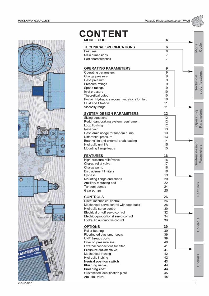
TTECHNICAL SPECIFICATIONS
Features
PM25-20 PM25-25 PM25-28
Displacement cm³/rev[in³/rev.]
20,5 [1.25]
25,7[1.57]
28[1.71]
Theoretical flow at rated speed (3600 rpm)
L/min[GPM]
73,8[19.50]
92,5[24.44]
100,8[26.63]
Max. Theoretical absorbed power at 320 bar [4 641 PSI] KW 39,4 49,3 53,8
Theorical absorbed torqueat 100 bar [1 450 PSI]
N.m[in.lbf]
32,6[288]
40,9[362]
44,6[395]
Moment of inertia kg.m²[slug.ft²] 0.0014 [0.0010]
Internal charge pump cm3/rev[in3/rev]
9,1 [0.55] or 12 [0.73]
Charge relief valve setting bar [PSI] From 10 [145] to 30 [435]
High pressure relief setting bar [PSI] Max. 350 [5 076]
Mounting flange SAE B
Mass kg [lb]18 [39.7] with control M
22,2 [48.9] with controls A, B, C, P, S24,7 [54.4] with control D
¨

POCLAIN HYDRAULICS Variable displacement pump - PM25
29/05/2017 7
Syst
em d
esig
n Pa
ram
eter
sM
odel
Cod
eO
pera
ting
Para
met
ers
Tech
nica
l sp
ecifi
catio
nsFe
atur
esO
ptio
nsC
ontr
ols
Main dimensions
PM 25 - SAE B - splined shaft with servo hydraulic control and without auxiliary mounting pad
Port characteristics
2 5 S41 2
A3 4 5
P M6 11107
S8 9
63 [2
.48]
118
[4.6
5]
91 [3.58]
48[1
.89]
48[1
.89]
90,5 [3.56]
X35
[1.3
8]
142 [5.59]
26 [1
.02]
88,5 [3.48]9,5 [0.37 ]0-0.05
0-0.002
26 [1
.02]
Ø 1
01,6
[dia
. 4.0
0
]
66,5
[2.6
2]
174 [6.85]
145 [5.71]
Ø 1
5 [d
ia. 0
.59]
91 [3.58]
27 [1
.06]
71 [2
.79]
68,5
[2.7
0]
138 [5.43]143,5 [5.65]
95 [3
.74]
43[1
.69]
33 [1
.30]
11,5
[0.4
5]
90 [3
.54]
88,5 [3.48]11 [0.43]
33 [1
.30]
11,5
[0.4
5]
11 [0.43]
195 [7.68]
+0 -0.0
54+0 -0
.002
View X
Clockwise (R)
Counterclockwise (L)
T1 S
M1
G2M2
T2
G1R
B
M4
A
M3
Port Function ISO 1179-1 (standard)
ISO 11926-1(option FU)
A-B Services 3/4’’ GAS 1 1/6-12-UNFG1/G2 Auxiliary 1/4’’ GAS 9/16-18-UNFM1/M2 A-B pressure 1/4’’ GAS 9/16-18-UNFM3/M4 Servo control pilot 1/4’’ GAS 9/16-18-UNFR Servo pilot pressure 1/4’’ GAS -S Suction 3/4’’ GAS 1 1/6-12-UNFT1/T2 Drain 1/2’’ GAS 3/4-16-UNF

PM25 - Variable displacement pump POCLAIN HYDRAULICS
8 29/05/2017

POCLAIN HYDRAULICS Variable displacement pump - PM25
29/05/2017 9
Syst
em d
esig
n Pa
ram
eter
sM
odel
Cod
eO
pera
ting
Para
met
ers
Tech
nica
l sp
ecifi
catio
nsFe
atur
esO
ptio
nsC
ontr
ols
OOPERATING PARAMETERSOperating parameters
PM25-20 PM25-25 PM25-28
Speed ratings
Minimummin-1(rpm)
700
Max. without load 3 900Max. with load 3 600
System pressure
Ratedbar [PSI]
250 [3 625]
Maximum 370 [5 366]
Minimum low loop 10 [145]
Inlet pressure
Mini continuous bar (abs.)[PSI abs.]
0,8 [11.6]
Mini (cold start) 0,5 [7.2]
Case pressure
Continuous bar [PSI]1,5 [21.7]
Maximum (cold start) 2,5 [36.2]
Charge pressure
Standard versionbar [PSI]
10 [145] for control M; 22 [319] for other controls
Max. charge pressure 30 [435]
Servo casepressure Maximum bar [PSI] 30 [435]
Charge pressure
A charge flow is required to maintain a positive pressure in the low pressure loop of a closed loop hydrostatic transmission. Charge pressure ensures proper lubrication and rotating group operation. It is recommended to maintain the charge pressure at a minimum of 10 bar [145 PSI] above case pressure. For more details, refer to charge pump paragraph, page 18.
Case pressure
Case pressure must be maintained within the limits shown in the table ''Operating parameters''. Ensure housing is always filled with hydraulic fluid and especially during start-up of the machine.
Pressure ratings
Maximum peak pressureIt is the maximum allowable pressure. It is equivalent to the maximum setting of the maximum high pressure relief valve. A self-propelled machine can reach the maximum peak pressure value no more than 1-2% of that work cycle.
Work cycleA fundamental factor for ensuring correct hydrostatic transmission sizing is the machine work cycle (pressure-time ratio, seasonality, pressure vs. percentage of time at max. displacement, machine type). Part service life depends on the correct choice in relation to the work cycle.
OverloadsIt is mandatory to protect parts against any possible overloads.
Speed ratings
The table ''Operating parameters'' gives minimum and maximum rated speeds. Note that all displacements might operate under different speed limits. Definitions of these speed limits appear below.
Maximum speed is the highest operating speed allowed. Over speeding reduces pump life time, can lead to loss of hydrostatic power and braking capacity. Never exceed the maximum speed limit under any operating conditions.
Nominal speed is the speed offering the maximal efficiency.

PM25 - Variable displacement pump POCLAIN HYDRAULICS
10 29/05/2017
Inlet pressure
Charge pump inlet pressure is key for acceptable pump life and performances. A continuous inlet pressure of not less than 0,8 bar abs. [11.6 PSI abs.] is recommended. A continuous inlet pressure less than 0.5 bar abs. [7.2 PSI abs.] indicates inadequate inlet design or a restricted filter. Pressures less than 0.5 bar abs. [7.2 PSI abs.] can happen at cold start, but should increase with oil temperature.
Theoretical output
Theoretical output flow is a function of pump displacement and speed. It is relevant to size the rest of the circuit. Theoretical flow does not take into account losses due to leakage or variations in displacement. Refer to performances, page 6, for volumetric and overall efficiencies at various operating speeds and pressures.
Poclain Hydraulics recommandations for fluidPoclain hydraulics recommends the use of hydraulic fluids defined by the ISO 15380 and ISO 6743-4 standards.For temperate climates, the following types are recommended.• HM 46 or HM 68 for fixed installations.• HV 46 or HV 68 for mobile installations.• HEES 46 for mobile installations.
These specifications correspond to category 91H of the CETOP standard, parts 1, 2 and 3 of the DIN 51524 standard, and grades VG32, VG 46 and VG68 of the ISO 6743-4 standards.
It is also possible to use ATF, HD, HFB, HFC or HFD type hydraulic fluid upon Poclain Hydraulics specific approval of the components’ operating conditions.
Standardized designations for the fluids• HM : Mineral fluids having specific antioxidant, anticorrosion and antiwear properties (HLP equivalent to DIN 51524
parts 1 and 2).• HV : HM mineral fluids providing improved temperature and viscosity properties (DIN 51524 part 3).• HEES :Biodegradable fluids based on organic esters.It is also possible to use a fluid that meets the biodegradability criteria and is compatible in the event of accidental food contact. The BIOHYDRAN FG 46 fluid designed by the company Total has undergone testing of its properties and performance on our test benches. Since this type of fluid has not yet been categorized, it is the responsibility of machine manufacturers to validate its compatibility with all of the components used in order to guarantee that the intended functions will be fulfilled and this for the desired life time of all equipment items.
During operation, the temperature of the oil must be between 0°C [32°F] and 80°C [176°F]; the minimum and maximum temperatures may be exceeded momentarily by ± 20°C [± 68°F] for a duration of less than 30 minutes.For all applications outside these limits, please consult with your Poclain Hydraulics’ application engineer.
For biodegradable fluids, consult your Poclain Hydraulics’ application engineer

POCLAIN HYDRAULICS Variable displacement pump - PM25
29/05/2017 11
Syst
em d
esig
n Pa
ram
eter
sM
odel
Cod
eO
pera
ting
Para
met
ers
Tech
nica
l sp
ecifi
catio
nsFe
atur
esO
ptio
nsC
ontr
ols
Fluid and filtration
The contaminating particles suspended in the hydraulic fluid cause the hydraulic mechanisms moving part wear. On hydraulic pumps, these parts operate with very small dimensional tolerances. In order to reach the part life, it is recommended to use a filter that maintains the hydraulic fluid contamination class at a max. of:
9 according to NAS 163822/18/13 according to ISO 4406:1999
According to the type of application decided for the pump, it is necessary to use filtration elements with a filtration ratio of:
20 to 30 100
Making sure that this ratio does not worsen together with the increasing of the filter cartridge differential pressure.
If these values cannot be observed, the component life will consequently be reduced and it is recommended to contact the Poclain Hydraulics Customer Service.
Filters on charge circuitFilters on the charge circuit (F0-F2) are designed without by-pass. The max. pressure drop on the filtration part must not exceed 2 bar [29 PSI] (3 bar [43.5 PSI] in case of cold starting) at pump full rating. To monitor the pressure drop, It is recommended to use the clogging indicator on the filtration element (F2 option). Contact your Poclain Hydraulics Application engineer, each time the pump is not charged by its internal charge pump. Filters on charge circuit are mounted on the pump special support.
Filters assemblingThe suction filter is mounted on the suction line. Check that the pressure before the charge pump is 0.8 bar abs. [11.6 PSI abs.], measured on the pump suction port (0.5 bar [7.2 PSI] for cold starting).
Viscosity range
For both max. efficiency and life of the unit, the operative viscosity should be chosen within the optimum range of:opt = optimum operating viscosity from 16 to 36 mm2/s [from 74.1 to 166.8 SUS] referred to the closed loop temperature.
Working conditions: the following limits of viscosity applymin = 5 mm2/s [23 SUS] short-duration at a max. permissible leakage oil temperature of 90° C [194°F]max = 1000 mm2/s [4 634 SUS] short-duration, on cold start.
VG 22VG 32VG 46VG 68
VG 100
-40
10
5
20
40
60
100
200
400600
10001600
46
23
93
185
278
463
927
1854278046347414
-25 -10 0 10 30 50 70 90 115
-40 -13 14 32 50 86 122 158 194 239
°C
[°F]
mm2/s [SUS]
Hydraulic fluid temperature range
For brief instants during the cold starting
Optimum viscosity
For b
rief i
nsta
nts
with
leak
age
oil a
t 90°
C
Ensure fluid temperature and viscosity limits are concurrently satisfied.
PM25 - Variable displacement pump POCLAIN HYDRAULICS
12 29/05/2017
SSYSTEM DESIGN PARAMETERSConsult your Poclain Hydraulics application engineer to validate your design parameters before using the pump in your application.
Sizing equations
The following equations are helpful when sizing hydraulic pumps. Generally, the sizing process is initiated by an evaluation of the machine system to determine the required motor speed and torque to perform the necessary work function. First, the motor is sized to transmit the maximum required torque. The pump is then selected as a flow source to achieve the maximum motor speed.
SI units
Output flow Q = (l/min)
Vg=Displacement per revolution cm3/tr [in3/rev]p = po - pi (system pressure) bar [PSI]
n = Speed min-1 [rpm]v = Volumetric efficiencym = Mechanical efficiencyt = Overall efficiency ( v. m)
Input torque M = (N.m)
Input power P = = (kW)
US units
Output flow Q = [GPM]
Input torque M = [lbf.in]
Input power P = = [hp]
Redundant braking system requirement
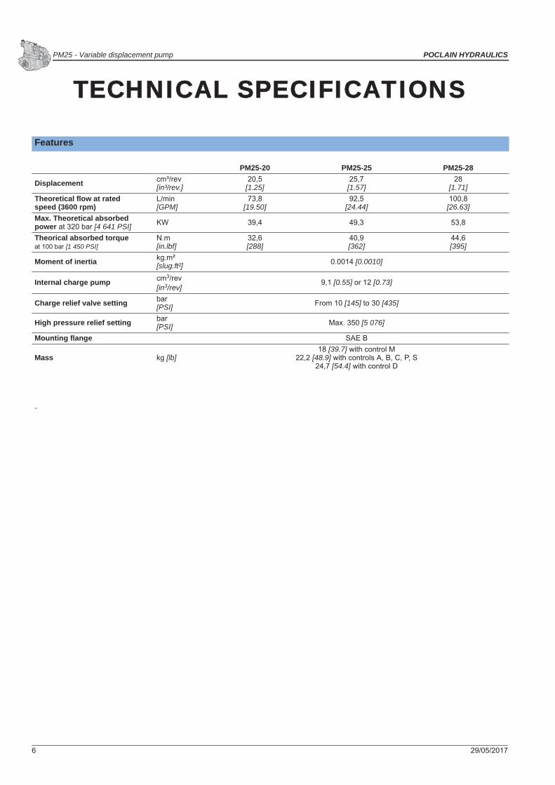
Loop flushing
Closed circuit may require a flushing valve to meet temperature and cleanliness requirements. A flushing valve takes a part of hot fluid flow from the low pressure loop of the system loop for cooling and filtering. Make sure that the charge pump provides adequate flow for the flushing valve flushing and the flushing valve does not cause charge pressure to drop below recommended limits..
Vg.n. v1000
Vg. p20. . m
M. n.30 000
Q. p600. t
Vg.n. v231
Vg. p2. . m
M.n.198 000
Q. p1714. t
Unintended vehicle or machine movement hazard.The loss of hydrostatic drive line power, in any mode of operation (forward, neutral, or reverse) may cause the system to lose hydrostatic braking capacity. You must provide a braking system, redundant to the hydrostatic transmission, sufficient to stop and hold the vehicle or machine in the event of hydrostatic drive power loss.
B
A
ST1 T2
M4M3
M1G1 G2 R M2
See option VS page 44 for more information
POCLAIN HYDRAULICS Variable displacement pump - PM25
29/05/2017 13
Syst
em d
esig
n Pa
ram
eter
sM
odel
Cod
eO
pera
ting
Para
met
ers
Tech
nica
l sp
ecifi
catio
nsFe
atur
esO
ptio
nsC
ontr
ols
Reservoir
The reservoir provides clean fluid, dissipates heat, and removes entrained air from the hydraulic fluid. It allows for fluid volume changes associated with fluid expansion and cylinder differential volumes. Minimum reservoir capacity depends on the volume needed to perform these functions. Typically, a capacity of one half the charge pump flow (per minute) is satisfactory for a closed reservoir. Open circuit systems sharing a common reservoir require greater fluid capacity.
Locate the reservoir outlet (suction line) near the bottom, allowing clearance for settling foreign particles. Use a 100 - 125 μm screen covering the outlet port.
Place the reservoir inlet (return lines) below the lowest expected fluid level, as far away from the outlet as possible.
Use a baffle (or baffles) between the reservoir inlet and outlet ports to promote de-aeration and reduce fluid surging.
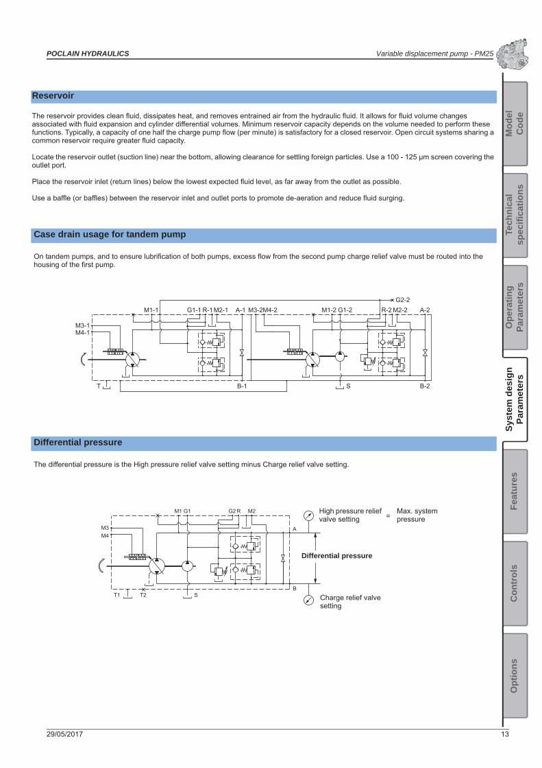
Case drain usage for tandem pump
On tandem pumps, and to ensure lubrification of both pumps, excess flow from the second pump charge relief valve must be routed into the housing of the first pump.
Differential pressure
The differential pressure is the High pressure relief valve setting minus Charge relief valve setting.
M1-1 A-1 M3-2M4-2 M1-2G2-2
B-2
M2-2G1-2R-1
S
M2-1
B-1
R-2
T
M3-1M4-1
A-2G1-1
M3M4
M1 M2
T1 T2 SB
A
G1 G2 R High pressure relief valve setting
Charge relief valve setting
Differential pressure
Max. system pressure=

PM25 - Variable displacement pump POCLAIN HYDRAULICS
14 29/05/2017
Bearing life and external shaft loading
Bearing life:
Bearing life is a function of speed, pressure , swashplate angle and external loads. Oil type and viscosity impact bearing life.
Normal bearing life in B10 hours is shown in the above table. Figures have been calculated under the following operating conditions : a continuous differential pressure of 130 bar [1 885 PSI], 1 800 rpm shaft speed, maximum displacement, without any external shaft side load. The data is based on a 50% forward, 50% reverse duty cycle, standard charge pump size, and standard charge pressure.
Shaft Loads:
PM25 pumps are designed with bearings that can accept external radial and thrust loads. The external radial shaft load limits depend on the load position, orientation, and operating conditions of the unit.
The maximum permissible radial load (Re), is based on the maximum external moment (Me), and the distance (L) from the mounting flange to the load. It may be determined using the table and formula below. Thrust (axial) load limits are also shown.
Re = Me / L
All external shaft loads affect bearing life. In applications with external shaft loads, minimize the impact by positioning the load at 90° or 270° as shown in the figure.
Contact your Poclain Hydraulics representative for an evaluation of unit bearing life if: • Continuously applied external loads exceed 25 % of the maximum allowable radial load Re.• The pump swashplate is positioned on one side of center all or most of the time.• The unit bearing life (B10) is critical.
Radial and thrust load position
Bearing life (B10 hours)
PM25-28 12 900
External moment (Me)N.m [in.lbf]
Maximum shaft thrust in (Tin)N [lbf]
PM25-28 44 [389] 1 000 [224.8]
at 120 bar [1 740 PSI] and 3 600 rpm
L
Re
TinTout
0° Re
180° Re
90° Re 270° Re
End view of shaft
Axis of swashplate rotation
For an accurate calculation, consult your Poclain Hydraulics application engineer.

POCLAIN HYDRAULICS Variable displacement pump - PM25
29/05/2017 15
Syst
em d
esig
n Pa
ram
eter
sM
odel
Cod
eO
pera
ting
Para
met
ers
Tech
nica
l sp
ecifi
catio
nsFe
atur
esO
ptio
nsC
ontr
ols
Hydraulic unit life
Hydraulic unit life is the life expectancy of the hydraulic components. It depends on speed and system pressure even if , system pressure is the dominant operating variable. High pressure, generated by high load, reduces hydraulic unit life.
Design the hydraulic system according to the expected machine duty cycle. Take in consideration the expected percentages of time at various loads and speeds. Ask your Poclain Hydraulics representative to calculate an appropriate pressure based your hydraulic system design. If duty cycle data is not available, input power and pump displacement are used to calculate system pressure.
All pressure limits are differential pressures (referenced to charge pressure) , taking a normal charge pressure in consideration.
PM25 pumps will meet satisfactory life expectancy if applied within the parameters specified in this technical documentation. For more detailed information on hydraulic unit life see Operating Parameters in page 9.
Mounting flange loads
Adding tandem mounted pumps, and/or tandem auxillary pump(s), subjecting pumps to shock loads may generate excessive loads on the front mounting flange. The overhung load moment for multiple pump mounting can be estimated as shown in the figure bellow
Overhung load example
Estimating overhung load moments
W = Weight of pump (kg)L = Distance from mounting flange to pump center of gravity (CG)
MR = GR (W1L1 + W2L2 + ... + WnLn)MS = GS (W1L1 + W2L2 + ... + WnLn)
Where:MR = Rated load moment (N.m)MS = Shock load moment (N.m)GR*= Rated (vibratory) acceleration (G’s) (m/sec²)GS*= Maximum shock acceleration (G’s) (m/sec²)
*Calculations will be carried out by multiplying the gravity (g = 9.81 m/sec²) with a given factor. This factor depends on the application.
Allowable overhung load moment are shown in the above table. Exceeding these values requires additional pump support.
L1
L2
CGpump 2
CGpump 1 Auxiliary pad
Mounting flange
Rated moment (MR) N.m [in.lbf]
Shock load moment (MS) N.m [in.lbf]
PM25-20 370 [3 274] 600 [5 310]
PM25-25 370 [3 274] 600 [5 310]
PM25-28 370 [3 274] 600 [5 310]
For an accurate calculation, consult your Poclain Hydraulics application engineer.

PM25 - Variable displacement pump POCLAIN HYDRAULICS
16 29/05/2017
FFEATURESHigh pressure relief valve
The high pressure relief valves maintain circuit pressure in the proper range. The check valves allow charge flow to replenish the low pressure loop of the circuit. The high pressure relief valves ensure a high pressure protection of the high pressure loop of the circuit.
High pressure relief valves are available in a range of settings.
When high pressure relief valves are not desired, pumps is equipped with charge circuit check valves only.
High pressure relief valves are intended for transient overpressure protection and are notintended for continuous pressure control. Flow over relief valves for extended periods of timemay result in severe heat build up. High flows over relief valves may result in pressure levelsexceeding the nominal valve setting and potential damage to system components.
M3M4
M1G1 G2 R M2
A
BST2T1
Flow
ISO VG46 hydraulic fluid at 50°C [122°F]
300
200
100
0 25 50 75 100
6.6 13.2 19.8 26.4
400
4 351
2 900
1 450
5 801
bar PSI
L/minGPM
High pressurerelief valve
2 51 2 3 4 5
P M6 11107 8 9
High pressure relief valve
Available setting bar [PSI]
Without - 00
With
150 [2 175] 15
200 [2 900] 20
250 [3 625] 25
300 [4 351] 30
350 [5 076] 35
Pres
sure
The high pressure relief valve setting is not thedifferential pressure between A and B ports (seepage 13).
POCLAIN HYDRAULICS Variable displacement pump - PM25
29/05/2017 17
Syst
em d
esig
n Pa
ram
eter
sM
odel
Cod
eO
pera
ting
Para
met
ers
Tech
nica
l sp
ecifi
catio
nsFe
atur
esO
ptio
nsC
ontr
ols
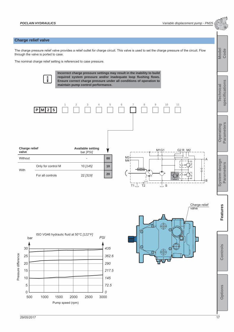
Charge relief valve
The charge pressure relief valve provides a relief outlet for charge circuit. This valve is used to set the charge pressure of the circuit. Flow through the valve is ported to case.
The nominal charge relief setting is referenced to case pressure.
Incorrect charge pressure settings may result in the inability to buildrequired system pressure and/or inadequate loop flushing flows.Ensure correct charge pressure under all conditions of operation tomaintain pump control performance.
30
25
20
15
10
5
0
435
362.6
290
217.5
145
72.5
0500 1000 1500 2000 2500 3000
bar PSI
M3M4
M1G1 G2 R M2
A
BST2T1
Pump speed (rpm)
Pre
ssur
e di
ffere
nce
ISO VG46 hydraulic fluid at 50°C [122°F]
Charge relief valve
2 51 2 3 4 5
P M6 11107 8 9
Charge relief valve
Available settingbar [PSI]
Without - 00
WithOnly for control M 10 [145] 10
For all controls 22 [319] 20

PM25 - Variable displacement pump POCLAIN HYDRAULICS
18 29/05/2017
Charge pump
Charge flow is required on all PM25 pumps used in closed circuit installations. The charge pump provides flow to make up internal leakage, maintain a positive pressure in the main circuit, provide flow for cooling and filtration, replace any leakage losses from external valving or auxiliary systems, and to provide flow and pressure for the control system.Many factors influence the charge flow requirements. These factors include system pressure, pump speed, pump swashplate angle, type of fluid, temperature, size of heat exchanger, length and size of hydraulic lines, control response characteristics, auxiliary flow requirements, hydrostatic motor type, etc.Unusual application conditions may require a more detailed review of charge pump sizing. Charge pressure must be maintained at a specified level under all operating conditions to prevent damage to the transmission. Poclain Hydraulics recommends testing under actual operating con-ditions to verify this.
Charge pump sizing/selection
In most applications a general guideline is that the charge pump displacement should be at least 20% of the main pump displacement.
M3M4
M1G1 G2 R M2
A
BST2T1
Charge pump Displacement cm³/rev [in³/rev]
Rated speed rpm
Without - - 00
With
For all auxiliary mounting pads 9,1 [0.55] 3900 08
Only auxiliary mounting pad A 12 [0.73] 3900 12
Contact your Poclain Hydraulics application engineer for more information.
2 51 2 3 4 5
P M6 11107 8 9

POCLAIN HYDRAULICS Variable displacement pump - PM25
29/05/2017 19
Syst
em d
esig
n Pa
ram
eter
sM
odel
Cod
eO
pera
ting
Para
met
ers
Tech
nica
l sp
ecifi
catio
nsFe
atur
esO
ptio
nsC
ontr
ols
Displacement limiters
PM25 are designed with mechanical displacement (stroke) limiters. You can limit maximum displacement of the pump to a certain per-cent of its maximum displacement to near zero in both direction.
The displacement limiters are located on the both sides of the servo piston and are adjustable by screw.
By-pass
PM25 features a by-pass function. By-passing Port A and Port B is achieved by unscrewing a screw located on the cover. The by-pass connect the ports A-B and must be use only in emergency case and only for short movement.
Take care in adjusting displacement limiters to avoid an undesirable condition of output flowor speed. Retorque the sealing lock nut after every adjustment to prevent an unexpectedchange in output conditions and to prevent external leakage during pump operation.
Max. displacement adjustement
Max. displacementadjustement
Neutral position adjustement
Max. displacement adjustement
Max. displacementadjustement
PM25 with control M PM25 with other controls
M3M4
M1G1 G2 R M2
A
BST2T1
By-pass valve is intended for moving a machine for very shortdistances at very slow speeds. It is NOT intended as tow valve.
To avoid leakage, do NOT exceed two turns of the screw.

PM25 - Variable displacement pump POCLAIN HYDRAULICS
20 29/05/2017
Mounting flange and shafts
SAE B - Splined shaft
S3 13 teeth Max. torque: 220 Nm [1947 in.lbf]
S4 15 teeth Max. torque: 360 Nm [3186 in.lbf]
2 51 2 3 4 5
P M6 11107 8 9
M6
16 [0.63]
9.50-0.05
41[1.61]
31 [1.22]
10 [0.39]
20 [0.79]
+0 -0.0
54Ø
101
,6
[dia
. 4.0
0
]
+0 -0
.002
+0 -0.0
54Ø
101
,6
[dia
. 4.0
0
]
M6
16 [0.63]
0-0.05
46[1.81]
38 [1.50]
8 [0.31]
25 [0.98]
9.5
+0 -0.0
02
Splined ANSI B92.1a-1996Pitch 16/32” DPPressure angle 30°Tolerance class: 5
Splined ANSI B92.1a-1996Pitch 16/32” DPPressure angle 30°Tolerance class: 5

POCLAIN HYDRAULICS Variable displacement pump - PM25
29/05/2017 21
Syst
em d
esig
n Pa
ram
eter
sM
odel
Cod
eO
pera
ting
Para
met
ers
Tech
nica
l sp
ecifi
catio
nsFe
atur
esO
ptio
nsC
ontr
ols
SAE B - Key shaft
Ø = 22,22 mm [dia. 0.87 in] Max. torque: 220 Nm [1947 in.lbf]
2 5 C31 2 3 4 5
P M6 11107 8 9
4,5[0.18]
25[0.98]
M8
25,0
8[0
.99
]
0 -0.2
6,35
[0
.25
] +0
.000
-0.0
36
0-0.05
33 [1.30]
8 [0.31]
9.541
[1.61]
19 [0.75]
+0 -0.0
54Ø
101
,6
[dia
. 4.0
0
]
+0 -0
.002
+0.0
00-0
.013
Ø 2
2,22
[d
ia. 0
.87
]
+0.0
00-0
.000
5
0 -0.0
8
+0.0
00-0
.001

PM25 - Variable displacement pump POCLAIN HYDRAULICS
22 29/05/2017
Auxiliary mounting pad
SAE A flange
00 Without charge pump
Max. Torque: 80 N.m [708 in.lbf]
8 With charge pump: 9,1 cm3/rev [0.55 in3/rev]
12 With charge pump: 12,0 cm3/rev [0.73 in3/rev]
2 51 2 3 4 5
P M6 11107
A8 9
Ø 1
06,4
[dia
. 4.1
9]
130,
4 [5
.13]
+0.0
71+0
.036
Ø 8
2,55
[d
ia. 3
.25
]
201 [7.91]
20 [0.79]
33,5[1.32]
35 [1.38]8 [0.31]
4 x
M10
+0.0
03+0
.001
Do not rotate the auxiliary mounting pad cover.
Splined ANSI B92.1a-1996Pitch 16/32” DPPressure angle 30°9 teethTolerance class: 5

POCLAIN HYDRAULICS Variable displacement pump - PM25
29/05/2017 23
Syst
em d
esig
n Pa
ram
eter
sM
odel
Cod
eO
pera
ting
Para
met
ers
Tech
nica
l sp
ecifi
catio
nsFe
atur
esO
ptio
nsC
ontr
ols
German group 2 flange
00 Without charge pump
Max. torque: 48 N.m [425 in.lbf]08 With charge pump: 9,1cm3/rev [0.55 in3/rev]
2 51 2 3 4 5
P M6 11107
G8 9
14,5 [0.57]
60 [2
.36]
30[1
.18]
115,4 [4.54]
100,
4 [3
.95]
+0.0
00+0
.030
Ø 5
2 [d
ia. 2
.04
]
6,5 [0.25]
2,5 [0.10]
39 [1.53] 8 [0.3
1
]
-0.0
25-0
.061
205 [8.07]
18[0.71]
8 x
M10
60 [2.36]
8 [0.31]
+0.0
00+0
.001
-0.0
01-0
.002
Do not rotate the auxiliary mounting pad cover.
Splined ANSI B92.1a-1996Pitch 16/32” DPPressure angle 30°9 teethTolerance class: 5

PM25 - Variable displacement pump POCLAIN HYDRAULICS
24 29/05/2017
Tandem pumps
Next pumpRear axial pump
Front axial pump
Me3 for the next pumpMe2 for the second pumpMe imput torque
Me1 for the first pump
Torque required by auxiliary pumps is additive. Ensure requirements don’t exceed shaft torque ratings.
2 51 2 3 4 5
P M6 11107
00 T8 9
2 5 T1P M
Front axial pump
Rear axial pump
+
Number of charge pump in the tandem
Axial pump
Mounting flange and shaft
Charge pump
Auxiliary mounting flange
0 charge pump
FrontSAE B; 13 teeth S3
Without 00 Tandem fitting TSAE B; 15 teeth S4
RearShaft for
secondary tandem pump
T1 Without 00SAE A flange A
Without auxiliary mounting pad S
1 charge pump*
FrontSAE B; 13 teeth S3
Without 00 Tandem fitting TSAE B; 15 teeth S4
RearShaft for
secondary tandem pump
T1 With08or 12
SAE A flange AWithout auxiliary
mounting pad S
Max. torque intermediate coupling200 N.m [1 770 in.lbf]
* The charge pump can only be located on the rear axial pump.Ports T and G of the first pump must be connected with ports T and G of the second pump.

POCLAIN HYDRAULICS Variable displacement pump - PM25
29/05/2017 25
Syst
em d
esig
n Pa
ram
eter
sM
odel
Cod
eO
pera
ting
Para
met
ers
Tech
nica
l sp
ecifi
catio
nsFe
atur
esO
ptio
nsC
ontr
ols
Gear pumps
M1-1 A-1 M3-2M4-2 M1-2G2-2
B-2
M2-2G1-2R-1
S
M2-1
B-1
R-2
T
M3-1M4-1
A-2G1-1
Displacement Pressure Dimension Mass EfficiencyContinuous
max. pressure
Max. intermittent pressure
Max. peak pressure A B C
cm3/rev [cu.in/rev] bar [PSI] bar [PSI] bar [PSI] mm [in] mm [in] mm [in] Kg [lb] %
G
German group 204 4
[0.24]250
[3 625]270
[3 915]290
[4 205]90,3
[3.55]
88[3.46]
100[3.94]
2,30[5.07]
95*
06 6,0 [0.37]
250 [3 625]
270 [3 915]
290 [4 205]
93,6[3.68]
2,45[5.40]
08 8,5 [0.52]
250 [3 625]
270 [3 915]
290 [4 205]
97,8[3.85]
2,60[5.73]
11 11,0 [0.67]
250 [3 625]
270 [3 915]
290 [4 205]
101,9[4.01]
2,70[5.95]
14 14[0.85]
250 [3 625]
270 [3 915]
290 [4 205]
106,9[4.21]
2,80[6.17]
17 16,5[1.01]
230 [3 335]
240 [3 480]
250 [3 625]
111,1[4.37]
2,95[6.51]
20 19,5 [1.19]
210 [3 045]
220 [3 190]
230 [3 335]
116,1[4.57]
3,10[6.84]
A
SAE A flange
04 4[0.24]
250 [3 625]
270 [3 915]
290 [4 205]
93,0[3.66]
130,4[5.13]
95[3.74]
2,30[5.07]
95*
06 6,0 [0.37]
250 [3 625]
270 [3 915]
290 [4 205]
96,3[3.68]
2,45[5.40]
08 8,5 [0.52]
250 [3 625]
270 [3 915]
290 [4 205]
100,5[3.96]
2,60[5.73]
11 11,0 [0.67]
250 [3 625]
270 [3 915]
290 [4 205]
104,6[4.12]
2,70[5.95]
14 14[0.85]
250 [3 625]
270 [3 915]
290 [4 205]
109,6[4.21]
2,80[6.17]
17 16,5[1.01]
230 [3 335]
240 [3 480]
250 [3 625]
113,8[4.37]
2,95[6.51]
20 19,5 [1.19]
210 [3 045]
220 [3 190]
230 [3 335]
118,8[4.68]
3,10[6.84]
22 22,5 [1.37]
190 [2 755]
200 [2 900]
210 [3 045]
123.8[4.87]
3,25[7.17]
26 26 [1.59]
170 [2 465]
180 [2 610]
190 [2 755]
129,6[5.10]
3,40[7.50]
* Value collected during the testing at 1500 rpm
A
B
C
A
B
C
Gear pumps are always delivered flanged on the axial pump. They can not be sold alone.
2 51 2 3 4 5
P M6 11107 8 9
Auxiliary mounting pad
Gear pump
PM25 - Variable displacement pump POCLAIN HYDRAULICS
26 29/05/2017
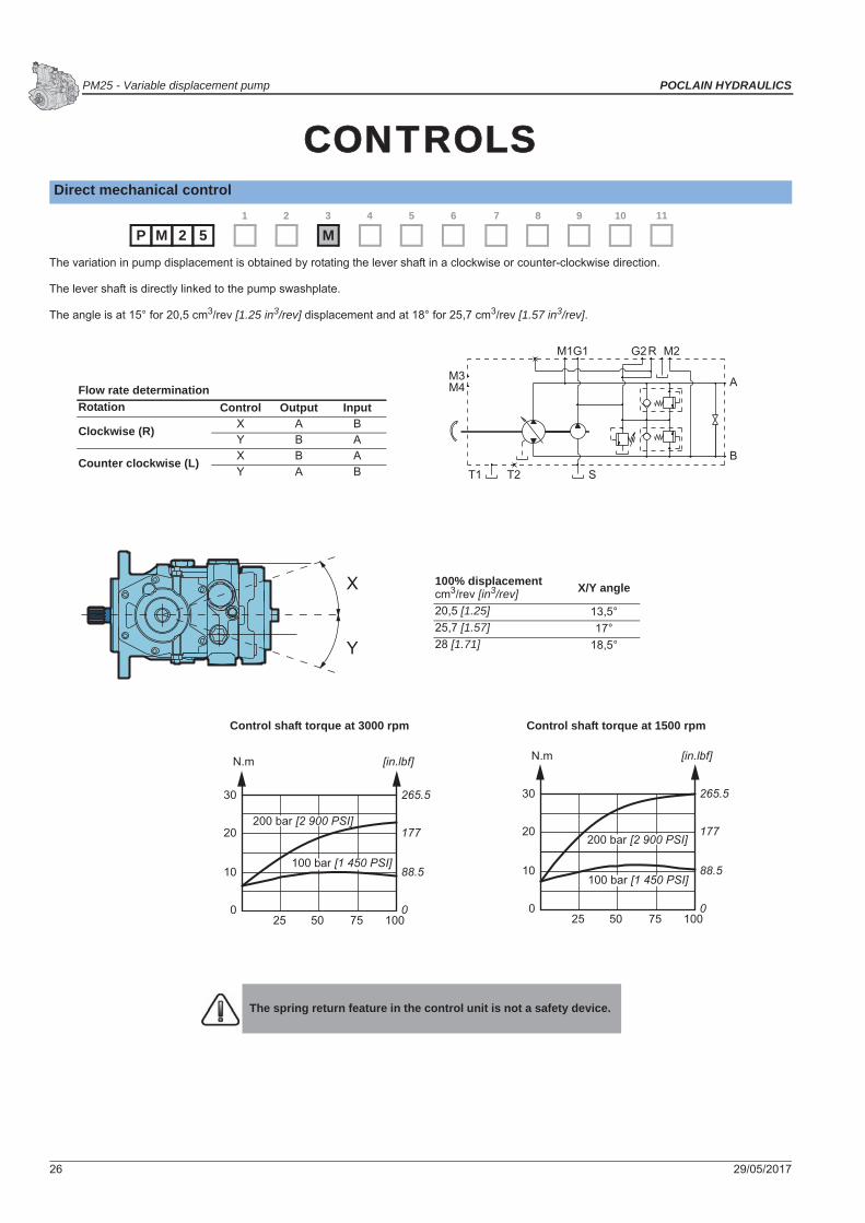
CCONTROLSDirect mechanical control
The variation in pump displacement is obtained by rotating the lever shaft in a clockwise or counter-clockwise direction.
The lever shaft is directly linked to the pump swashplate.
The angle is at 15° for 20,5 cm3/rev [1.25 in3/rev] displacement and at 18° for 25,7 cm3/rev [1.57 in3/rev].
2 51 2
M3 4 5
P M6 11107 8 9
30
20
10
025 50 75 100
265.5
177
88.5
0
N.m [in.lbf]
200 bar [2 900 PSI]
100 bar [1 450 PSI]
30
20
10
025 50 75 100
265.5
177
88.5
0
N.m [in.lbf]
200 bar [2 900 PSI]
100 bar [1 450 PSI]
X
Y
G2M1 M2
B
A
T1 T2 S
G1 R
M3M4Flow rate determination
Rotation Control Output Input
Clockwise (R) X A BY B A
Counter clockwise (L) X B AY A B
100% displacement cm3/rev [in3/rev] X/Y angle
20,5 [1.25] 13,5°25,7 [1.57] 17°28 [1.71] 18,5°
Control shaft torque at 3000 rpm Control shaft torque at 1500 rpm
The spring return feature in the control unit is not a safety device.

POCLAIN HYDRAULICS Variable displacement pump - PM25
29/05/2017 27
Syst
em d
esig
n Pa
ram
eter
sM
odel
Cod
eO
pera
ting
Para
met
ers
Tech
nica
l sp
ecifi
catio
nsFe
atur
esO
ptio
nsC
ontr
ols
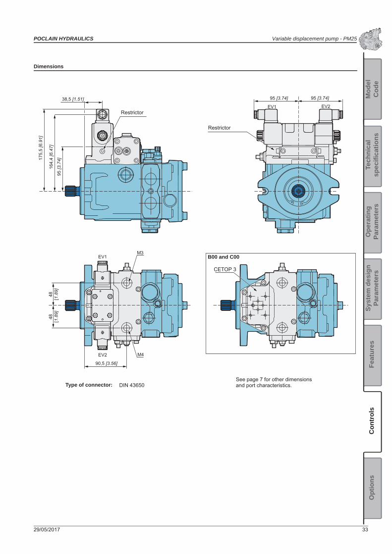
Dimensions
63 [2
.48]
85 [3
.35]
93,5
[3.6
8]
103
[4.0
5]
Ø 18 [dia. 0.71] Ø 6 [dia. 0.24]
60,5[2.38]
See page 7 for other dimensions and port characteristics.

PM25 - Variable displacement pump POCLAIN HYDRAULICS
28 29/05/2017
Mechanical servo control with feed back
The variation in pump displacement is obtained by rotating the drive lever situated on the servo control. An internal channel, linked to the charge pump, feeds a hydraulic servo valve which supplies oil into the cylinder which is in turn linked to the pump swashplate.The maximum rotation of the Iever, with respect to 0 is 42,5° for both rotation directions; thus permitting the optimum control of the displacement.
At every lever angle there is a corresponding pump displacement. On the (T) return ’’arm’’ of the rotating distributor a restrictor (Rs) is mounted which regulates the servo control shifting speed, thus avoiding sudden accelerations and stoppages.
The effort of moving the lever is independent of the pressure and rpm.
2 51 2
A3 4 5
P M6 11107 8 9
3
2
1
-1
-2
-3
0
26.5
17.7
8.85
-8.85
-17.7
-26.5
0
10 20 30 40-40 -30 -20 -10
N.m [in.lbf]
0
S
M4M3
M1 M2G1
T1 T2
B
A
G2 RRs
42,5° max.
42,5
° max
.
X
Y
Flow rate determinationRotation Control Output Input
Clockwise (R) X A BY B A
Counter clockwise (L) X B AY A B
Control shaft rotation (degrees)
To prevent damage to the control A a positivemechanical stop must be provided for thecontrol A linkage.
Control lever torque vs Control leverrotation
The spring return feature in the control unit is not a safety device.

POCLAIN HYDRAULICS Variable displacement pump - PM25
29/05/2017 29
Syst
em d
esig
n Pa
ram
eter
sM
odel
Cod
eO
pera
ting
Para
met
ers
Tech
nica
l sp
ecifi
catio
nsFe
atur
esO
ptio
nsC
ontr
ols
Dimensions
45[1.77]
50,5[1.99]
132,
5 [5
.21]
48[1
.89]
123,
5 [4
.86]
21,5[0.85]
90,5 [3.56]
15 [0.59]
26[1
.02]
166
[6.5
3]
3[0
.12]
3 x Ø 9 [dia. 0.35]
0-0.05Ø 12
[dia. 0.47 ] 0-0.002
48[1
.89]
See page 7 for other dimensions and port characteristics.
Restrictor

PM25 - Variable displacement pump POCLAIN HYDRAULICS
30 29/05/2017
Hydraulic servo control
The variation in pump displacement is obtained by adjusting the pressure on the M3 and M4 servo control connections by means of a hydraulic proportional joystick (containing pressure reduction valves).
The joystick supply can by obtained by taking pressure from the auxiliary pump (G connection).
The servo control response time can be adjusted by inserting a restrictor on the joystick supply line (from 0.6 to 1,2 mm [from 0.02 to 0.05 in] or between the joystick and servo piston of the pump.
The servo control operation curve in both control directions goes from 6 to 15 bar [from 87 to 217 PSI]. The adjustment curve of the hydraulic control system has to be wider (from 5 to 16 bar [from 72.5 to 232 PSI]).
2 51 2
S3 4 5
P M6 11107 8 9
S
M4M3
M1 M2G1
T1 T2
B
A
G2 R
20
15
10
5
290
217.5
145
72.5
0 50 100
bar [PSI]
Flow rate determinationRotation Pressure Output Input
Clockwise (R) M3 B AM4 A B
Counter clockwise (L) M3 A BM4 B A
Pump displacement (%)
Restrictors
The spring return feature in the control unit is not a safety device.

POCLAIN HYDRAULICS Variable displacement pump - PM25
29/05/2017 31
Syst
em d
esig
n Pa
ram
eter
sM
odel
Cod
eO
pera
ting
Para
met
ers
Tech
nica
l sp
ecifi
catio
nsFe
atur
esO
ptio
nsC
ontr
ols
Dimensions
118
[4.6
5]
91 [3.58]
48[1
.89]
48[1
.89]
90,5 [3.56]
91 [3.58]
10
[0.3
9]
M3
M4
See page 7 for other dimensions and port characteristics.
Restrictor

PM25 - Variable displacement pump POCLAIN HYDRAULICS
32 29/05/2017
Electrical on-off servo control
Control with return spring
The reaching of the maximum displacement in a time defined by the restrictors (Rs) which are positioned between the electrovalve and the (T) drain is obtained by the continuous starting of an ON-OFF electrovalve with an open-circuit CETOP 3 connection.
If the electro-valve motion is stopped, the pump goes back to “0” position thanks to the servo control springs.
The pump can be supplied either without electrovalve (B00) or with electrovalve (B12, B24 ).
Control without return spring
The variation in pump displacement is obtained by the energizing of an ON-OFF electro-valve with a closed center CETOP 3 connection.
The displacement reached is in relation to the starting time of the electro-valve and to the diameter of the restrictors (Rs) which are placed between the electrovalve and the drain (T).
The pump can be supplied either without electrovalve (C00) or with electrovalve (C12, C24).
The servo control is without springs and the setting of the pump at a certain displacement is guaranteed by the closed center of the electrovalve.
2 51 2 3 4 5
P M6 11107 8 9
M3M4
T1 T2 S
M2
B
A
M1 G1 G2 R
M3M4
T1 T2 S
M2
B
A
M1 G1 G2 R
t a b p
EV2 EV1
Rs Rs
Rs Rs
2 51 2 3 4 5
P M6 11107 8 9
M3M4
T1 T2 S
M2
B
A
M1 G1 G2 R
M3M4
T1 T2 S
M2
B
A
M1 G1 G2 R
t a b p
EV2 EV1
Rs Rs
Rs Rs
Flow rate determinationRotation Control Pressure Output Input
Clockwise (R) EV1 A A BEV2 B B A
Counter clockwise (L) EV1 A B AEV2 B A B
The spring return feature in the control unit is not a safety device.
Supply voltage
Without B00
12V B12
24V B24
Supply voltage
Without C00
12V C12
24V C24
POCLAIN HYDRAULICS Variable displacement pump - PM25
29/05/2017 33
Syst
em d
esig
n Pa
ram
eter
sM
odel
Cod
eO
pera
ting
Para
met
ers
Tech
nica
l sp
ecifi
catio
nsFe
atur
esO
ptio
nsC
ontr
ols
Dimensions
164,
4 [6
.47]
95 [3
.74]17
5,5
[6.9
1]
95 [3.74]
48[1
.89]
48[1
.89]
90,5 [3.56]
95 [3.74]
M3
M4
38,5 [1.51]
EV1
EV2
EV1 EV2
See page 7 for other dimensions and port characteristics.Type of connector: DIN 43650
Restrictor
Restrictor
CETOP 3
B00 and C00

PM25 - Variable displacement pump POCLAIN HYDRAULICS
34 29/05/2017
Electrico-proportional servo control
By means of a potentiometer and a control card, a voltage signal is applied to the proportional electrovalve coils which adjust the pressure of the servo control connected to the pump swashplate.
At every position of the potentiometer lever, there is a corresponding swashplate position.
The flow rate direction depends on which coil is excited.
The adjustment speed can be controlled by ramps installed on the card and by restrictors (Rs) positioned between the electrovalve and the servo control.
2 51 2 3 4 5
P M6 11107 8 9
G1M1 M2
B
A
T1 T2 S
M3M4
G2 R
EP2
Rs
EP1
Rs
600
800
1000
1200
1400
0 50 100
300
400
500
600
700
Flow rate determinationRotation Pressure Output Input
Clockwise (R) EP1 B AEP2 A B
Counter clockwise (L) EP1 A BEP2 B A
Pump displacement (%)
Cur
rent
(mA
) (12
V)
Cur
rent
(mA
) (24
V)
The current must not exceed 1500 mAunder 12V and 800 mA under 24V.
The spring return feature in the control unit is not a safety device.
Supply voltage
12V P12
24V P24

POCLAIN HYDRAULICS Variable displacement pump - PM25
29/05/2017 35
Syst
em d
esig
n Pa
ram
eter
sM
odel
Cod
eO
pera
ting
Para
met
ers
Tech
nica
l sp
ecifi
catio
nsFe
atur
esO
ptio
nsC
ontr
ols
Dimensions
165,
5 [6
.51]
48[1
.89]
48[1
.89]
43[1.69]
68 [2
.68]
68,4
[2.6
9]
90,5 [3.56]
M3
M4
EP1
EP2
EP1 EP2
See page 7 for other dimensions and port characteristics.
Type of connector: DIN 43650
Restrictor
Restrictor
PM25 - Variable displacement pump POCLAIN HYDRAULICS
36 29/05/2017
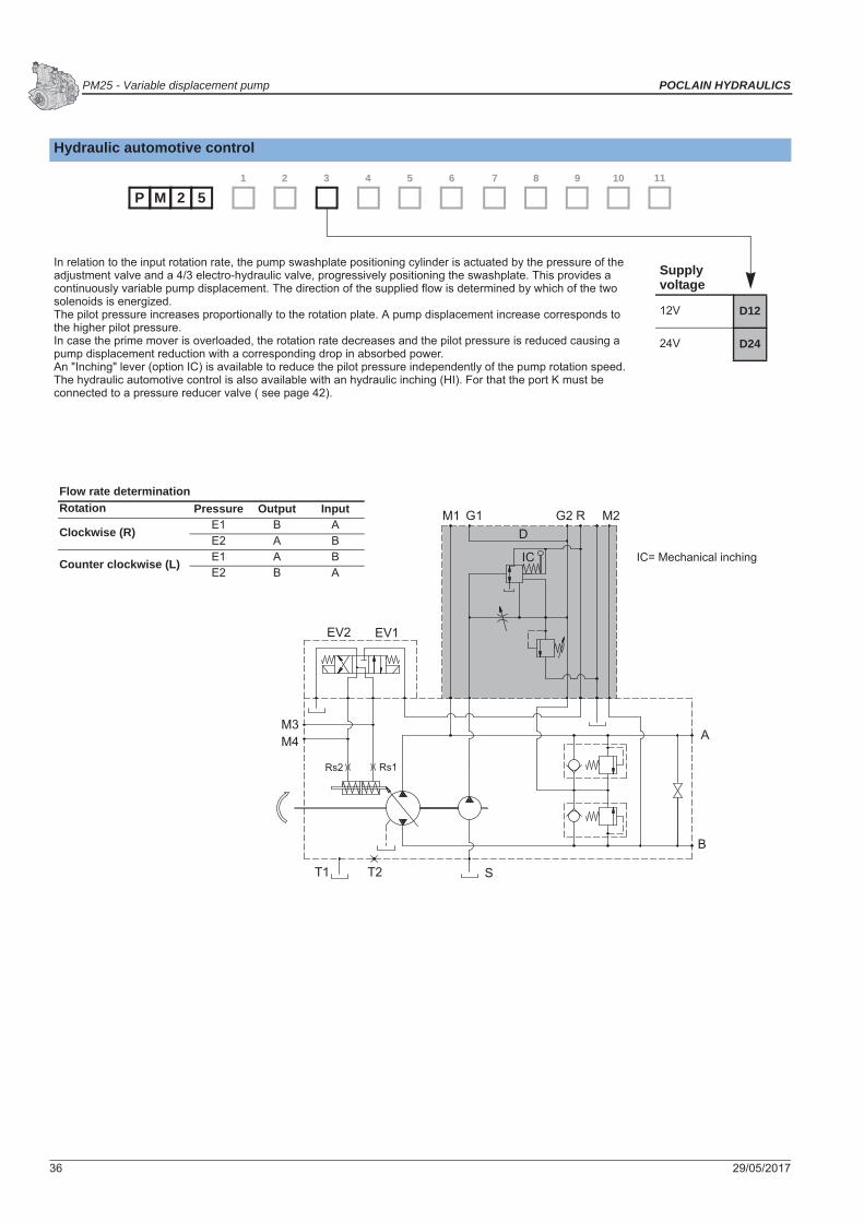
Hydraulic automotive control
In relation to the input rotation rate, the pump swashplate positioning cylinder is actuated by the pressure of the adjustment valve and a 4/3 electro-hydraulic valve, progressively positioning the swashplate. This provides a continuously variable pump displacement. The direction of the supplied flow is determined by which of the two solenoids is energized.The pilot pressure increases proportionally to the rotation plate. A pump displacement increase corresponds to the higher pilot pressure.In case the prime mover is overloaded, the rotation rate decreases and the pilot pressure is reduced causing a pump displacement reduction with a corresponding drop in absorbed power.An "Inching" lever (option IC) is available to reduce the pilot pressure independently of the pump rotation speed. The hydraulic automotive control is also available with an hydraulic inching (HI). For that the port K must be connected to a pressure reducer valve ( see page 42).
2 51 2 3 4 5
P M6 11107 8 9
M3M4
T1 T2 S
M2
B
A
M1 RG1 G2D
IC
Rs1Rs2
EV2 EV1
Flow rate determinationRotation Pressure Output Input
Clockwise (R) E1 B AE2 A B
Counter clockwise (L) E1 A BE2 B A
IC= Mechanical inching
Supply voltage
12V D12
24V D24

POCLAIN HYDRAULICS Variable displacement pump - PM25
29/05/2017 37
Syst
em d
esig
n Pa
ram
eter
sM
odel
Cod
eO
pera
ting
Para
met
ers
Tech
nica
l sp
ecifi
catio
nsFe
atur
esO
ptio
nsC
ontr
ols
Dimensions with option IC
164,
4 [6
.47]
71 [2
.80]
175,
5 [6
.91]
134 [5.27]
48[1
.89]
48[1
.89]
90,5 [3.56]
95 [3.74]
M3
M4
38,5 [1.51]
EV1
EV2
EV1 EV2
45[1.77]
84,75 [3.34]15,25[0.60]
15[0.59]
94 [3
.70]
3[0
.12]
3 x Ø 9 [dia. 0.35]
Mechanical inching lever
See page 7 for other dimensions and port characteristics.
Restrictor Restrictor
Port K

PM25 - Variable displacement pump POCLAIN HYDRAULICS
38 29/05/2017

POCLAIN HYDRAULICS Variable displacement pump - PM25
29/05/2017 39
Syst
em d
esig
n Pa
ram
eter
sM
odel
Cod
eO
pera
ting
Para
met
ers
Tech
nica
l sp
ecifi
catio
nsFe
atur
esO
ptio
nsC
ontr
ols
OOPTIONSRoller bearing
It is an optional high capacity bearing.
Depending on the characteristics of shaft load, the duty cycle of the application and the expected life time of your application, Roller bearing might be needed.
Consult your Poclain Hydraulics Application Engineer.
Fluorinated elastomer seals
Standard NBR sealing are designed to resist to temperature up to 90°C [194°F] and to HV type oils.
If your application is outside these limits, Fluorinated elastomer seals might be recommended.
Consult your Poclain Hydraulics Application Engineer.
UNF threads ports
2 51 2 3 4 5
P M6
CR11107 8 9
2 51 2 3 4 5
P M6 11
EV107 8 9
Port Function ISO 11926-1A-B Services 1 1/6-12-UNFG Auxiliary 9/16-18-UNFM1/M2 Gauge 9/16-18-UNFM3/M4 Servo control pilot 9/16-18-UNFS Suction 1 1/6-12-UNFT1/T2 Drain 3/4-16-UNF
T1 S
M1
G2M2
T2
G1R
B
M4
A
M3
2 51 2 3 4 5
P M6 11
FU107 8 9

PM25 - Variable displacement pump POCLAIN HYDRAULICS
40 29/05/2017
Filter on pressure line
The PM25 pumps can have a pressure filter without clogging indicator (F0) or with clogging indicator (F2). The flow thru the filter is only the flow that entry in the close loop. The filter fitness is of 10 micron.
The max. working pressure is 30 bar [435 PSI].
Maximum pressure difference between filter cartridge input and output is 2 bar [29 PSI]. When reaching 2 bar [29 PSI], the cartridge has to be changed.
Tightening torque: 35 Nm [309 in.lbf].
F0 Without clogging indicator F2 With clogging indicator
2 51 2 3 4 5
P M6 11107 8 9
115,
5 [4
.55]
94,5 [3.72]
M3
M4
M2
G2
G1
M1
150
[5.9
0]
Ø 6
2 [d
ia. 2
.44]
142
[5.5
9]
35 [1.38]
M1
M3M4
M2G2G1
T1 T2 S
A
B
M1
M3M4
M2G2G1
T1 T2 S
A
B
NC
2 bar [29 PSI]
12
1 2
Clogging indicator
Normally closed contact.Thread of the clogging indicator is internally connected to ground.
Clogging indicator specificationDifferential working adjustment
3 ± 0,2 bar[44 ± 3 PSI]
Working temperature -30°C ~ 110 °C[-22°F ~ 230°F]
Max. vibration level 50 g
Connector type AMP super seal, 2 way
Current range 0,1-0,2 A max.

POCLAIN HYDRAULICS Variable displacement pump - PM25
29/05/2017 41
Syst
em d
esig
n Pa
ram
eter
sM
odel
Cod
eO
pera
ting
Para
met
ers
Tech
nica
l sp
ecifi
catio
nsFe
atur
esO
ptio
nsC
ontr
ols
The function of the cut-off valve is to avoid that the pump absorbed power exceeds the machine engine power.The cut-off valve is connected to A and B piston pump’s high pressure lines and is usually set at 20 to 30 bar [290 to 435 PSI] lower thanthe maximum relief valve of the closed circuit.The cut-off valve acts on the servo control operating pressure in order to reduce the pump displacement and the adsorbed power.
External connections for filter
Pressure cut-off valve
Max deep of the nipples for the connections M1-M2 andG1-G2-R must be 10 mm.
2 51 2 3 4 5
P M6
F311107 8 9
11 [0.43] 11 [0.43]
33 [1
.30]
11,5
[0.4
5]
33 [1
.30]
11,5
[0.4
5]
M2
G2
M6
M3M4
M5M1G1G2
A
B
M2
T1T2S
Rs1Rs2
RC
M1
R
G1
C
G1 = to filter on lineG2 = Return from filter on line
2 51 2 3 4 5
P M6
LP11107 8 9
0.8
S
M4M3
M1 M2G1
T1 T2
B
A
G2 R
113
[4.4
5]
M2
G2
G1
M1
R
XView X
Pressure cut-off setting

PM25 - Variable displacement pump POCLAIN HYDRAULICS
42 29/05/2017
For hydraulic automotive control D. An "Inching" lever is available to reduce the pilot pressure independently of the pump rotation speed.See Hydraulic automotive control (D) page 36.
Mechanical inching
Hydraulic inching
2 51 2 D12
34 5
P M6
IC11107 8 9
D24or
2 51 2 D12
34 5
P M6
HI11107 8 9
D24or
For hydraulic automotive control D is available an hydraulic inching HI that consist in a connection K on the pump body to be connect witha pressure reducer valve (for example brake pedal VB002 or VB012). See hydraulic automotive control (page 36).
M1 G1 G2
A
B
K
M3M4
BH
D
T1T2
R M2
S
Rs1Rs2
C
M1
R KRs1
G2
M2
C T1
G1
49
61.5[2.42]
[1.6
5]
Port Function ISO 1179-1K External servo pilot 1/8’’ GAS
Towards hydraulicjoystick
From hydraulicjoystick

POCLAIN HYDRAULICS Variable displacement pump - PM25
29/05/2017 43
Syst
em d
esig
n Pa
ram
eter
sM
odel
Cod
eO
pera
ting
Para
met
ers
Tech
nica
l sp
ecifi
catio
nsFe
atur
esO
ptio
nsC
ontr
ols
Neutral position switch
For the control A it is possible to obtain a micro switch to avoid the start of the engine if the lever of the control is not in center(zero position).
2 51 2 3 4 5
P M6
MI11107 8 9
M2
G2
G1
M1
R
S
M4M3
M1 M2G1
T1 T2
B
A
G2 RRs
50,5[1.99]
117,
5 [4
.62]
101 [3.98]
Type of connector: Deutsch DT04-2P

PM25 - Variable displacement pump POCLAIN HYDRAULICS
44 29/05/2017
Flushing valve
inside the pump cover, a purge valve can be fitted with discharge inside the pump casing by means of a calibrated hole. The exchange valve isuseful in case the temperature of the oil in the closed circuit is too high.
Finishing coat
The pumps can be delivered with finishing coat when requested. Standard paint is RAL 9005 (black color).
2 51 2 3 4 5
P M6
VS11107 8 9
B
A
ST1 T2
M4M3
M1 M2G1 G2 R
112
[4.4
1]
M2
G2
G1
M1
R
X
2 51 2 3 4 5
P M6
PA11107 8 9
Consult your Poclain Hydraulics application engineer for other colors of topcoat.
POCLAIN HYDRAULICS Variable displacement pump - PM25
29/05/2017 45
Syst
em d
esig
n Pa
ram
eter
sM
odel
Cod
eO
pera
ting
Para
met
ers
Tech
nica
l sp
ecifi
catio
nsFe
atur
esO
ptio
nsC
ontr
ols
Customized identification plate
It is possible to provide our products with dedicated plate (your part number engraved on the plate) when requested.
Anti-stall valve
SD option consists of a block valve (same body as automotive valve) which provide a pressure signal for the servo piston of the pump related to the speed of engine. In case of engine overload and consequent rpm reduction the SD valve reduces the pressure for the servo piston and the pump de-stroke consequentially with an anti-stall effect.
2 51 2 3 4 5
P M6
DP11107 8 9
This option is available only for minimum volume of 50 pieces.
Consult your Poclain Hydraulics application engineer for other possibilities.
2 51 2 3 4 5
P M6
SD11107 8 9
For application of this option please contactyour Poclain Hydraulics application engineer.

PM25 - Variable displacement pump POCLAIN HYDRAULICS
46 29/05/2017

POCLAIN HYDRAULICS Variable displacement pump - PM25
29/05/2017 47
Syst
em d
esig
n Pa
ram
eter
sM
odel
Cod
eO
pera
ting
Para
met
ers
Tech
nica
l sp
ecifi
catio
nsFe
atur
esO
ptio
nsC
ontr
ols

www.poclain-hydraulics.com
Poclain Hydraulics reserves the right to make any modifications it deems necessary to the products described in this document without prior notification.The information contained in this document must be confirmed by Poclain Hydraulics before any order is submitted.Illustrations are not binding.The Poclain Hydraulics brand is the property of Poclain Hydraulics S.A.
29/05/2017
A35767C
Recommended


![Ceramic Ball Bearing Turbo Molecular Pump [UTM300B ] · If ambient air temperature changes, an acceptable value will change. *4 Maximum outlet pressure and maximum inlet pressure](https://img.pdfslide.us/doc/110x75/5d4d98a688c9938a7e8bd5e5/ceramic-ball-bearing-turbo-molecular-pump-utm300b-if-ambient-air-temperature.jpg)