1
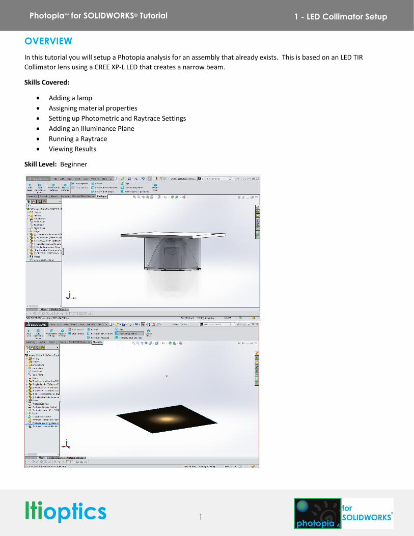
Photopia™ for SOLIDWORKS® Tutorial 1 - LED Collimator Setup
OVERVIEW
In this tutorial you will setup a Photopia analysis for an assembly that already exists. This is based on an LED TIR
Collimator lens using a CREE XP-L LED that creates a narrow beam.
Skills Covered:
Adding a lamp
Assigning material properties
Setting up Photometric and Raytrace Settings
Adding an Illuminance Plane
Running a Raytrace
Viewing Results
Skill Level: Beginner
2
Photopia™ for SOLIDWORKS® Tutorial 1 - LED Collimator Setup
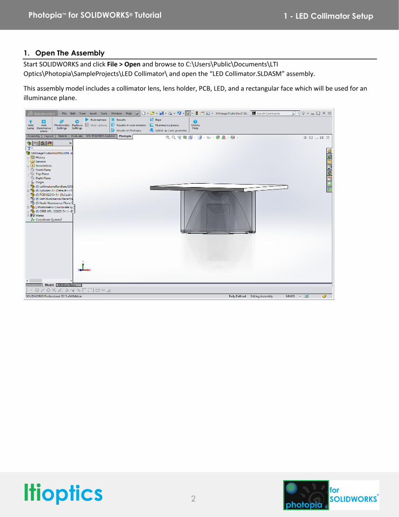
1. Open The Assembly
Start SOLIDWORKS and click File > Open and browse to C:\Users\Public\Documents\LTI
Optics\Photopia\SampleProjects\LED Collimator\ and open the “LED Collimator.SLDASM” assembly.
This assembly model includes a collimator lens, lens holder, PCB, LED, and a rectangular face which will be used for an
illuminance plane.
3
Photopia™ for SOLIDWORKS® Tutorial 1 - LED Collimator Setup
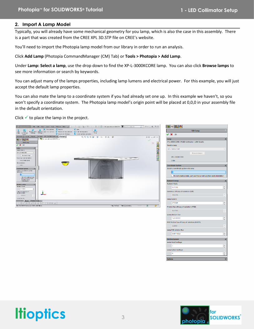
2. Import A Lamp Model
Typically, you will already have some mechanical geometry for you lamp, which is also the case in this assembly. There
is a part that was created from the CREE XPL 3D.STP file on CREE’s website.
You’ll need to import the Photopia lamp model from our library in order to run an analysis.
Click Add Lamp (Photopia CommandManager (CM) Tab) or Tools > Photopia > Add Lamp.
Under Lamp: Select a lamp, use the drop down to find the XP-L-3000KCORE lamp. You can also click Browse lamps to
see more information or search by keywords.
You can adjust many of the lamps properties, including lamp lumens and electrical power. For this example, you will just
accept the default lamp properties.
You can also mate the lamp to a coordinate system if you had already set one up. In this example we haven’t, so you
won’t specify a coordinate system. The Photopia lamp model’s origin point will be placed at 0,0,0 in your assembly file
in the default orientation.
Click to place the lamp in the project.
4
Photopia™ for SOLIDWORKS® Tutorial 1 - LED Collimator Setup
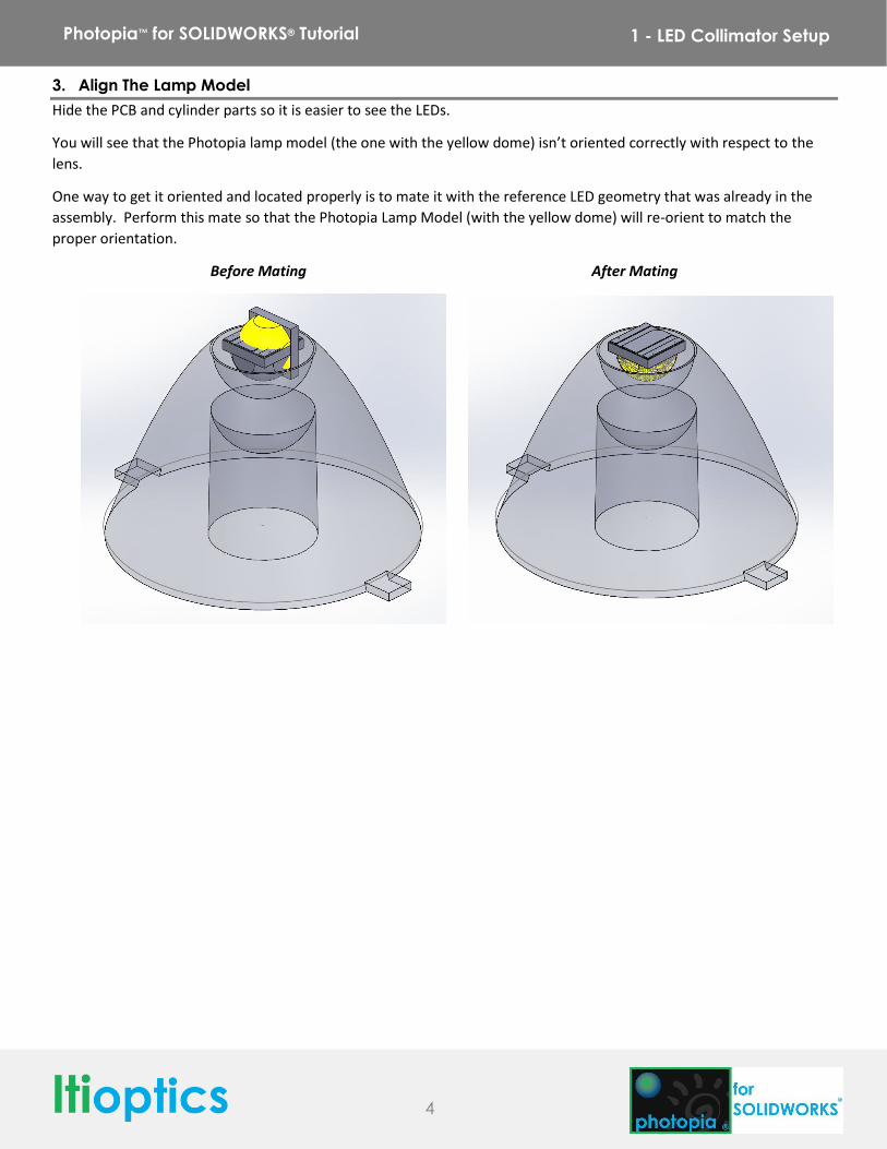
3. Align The Lamp Model
Hide the PCB and cylinder parts so it is easier to see the LEDs.
You will see that the Photopia lamp model (the one with the yellow dome) isn’t oriented correctly with respect to the
lens.
One way to get it oriented and located properly is to mate it with the reference LED geometry that was already in the
assembly. Perform this mate so that the Photopia Lamp Model (with the yellow dome) will re-orient to match the
proper orientation.
Before Mating After Mating
5
Photopia™ for SOLIDWORKS® Tutorial 1 - LED Collimator Setup
4. Assign Photopia Materials
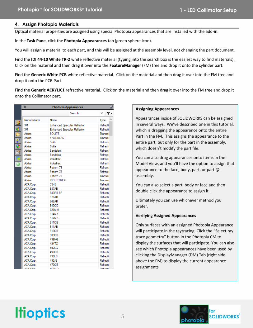
Optical material properties are assigned using special Photopia appearances that are installed with the add-in.
In the Task Pane, click the Photopia Appearances tab (green sphere icon).
You will assign a material to each part, and this will be assigned at the assembly level, not changing the part document.
Find the IDI 44-10 White TR-2 white reflective material (typing into the search box is the easiest way to find materials).
Click on the material and then drag it over into the FeatureManager (FM) tree and drop it onto the cylinder part.
Find the Generic White PCB white reflective material. Click on the material and then drag it over into the FM tree and
drop it onto the PCB Part.
Find the Generic ACRYLIC1 refractive material. Click on the material and then drag it over into the FM tree and drop it
onto the Collimator part.
Assigning Appearances
Appearances inside of SOLIDWORKS can be assigned
in several ways. We’ve described one in this tutorial,
which is dragging the appearance onto the entire
Part in the FM. This assigns the appearance to the
entire part, but only for the part in the assembly,
which doesn’t modify the part file.
You can also drag appearances onto items in the
Model View, and you’ll have the option to assign that
appearance to the face, body, part, or part @
assembly.
You can also select a part, body or face and then
double click the appearance to assign it.
Ultimately you can use whichever method you
prefer.
Verifying Assigned Appearances
Only surfaces with an assigned Photopia Appearance
will participate in the raytracing. Click the “Select ray
trace geometry” button in the Photopia CM to
display the surfaces that will participate. You can also
see which Photopia appearances have been used by
clicking the DisplayManager (DM) Tab (right side
above the FM) to display the current appearance
assignments
6
Photopia™ for SOLIDWORKS® Tutorial 1 - LED Collimator Setup
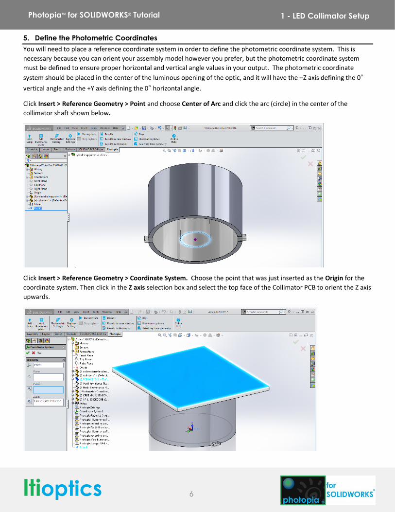
5. Define the Photometric Coordinates
You will need to place a reference coordinate system in order to define the photometric coordinate system. This is
necessary because you can orient your assembly model however you prefer, but the photometric coordinate system
must be defined to ensure proper horizontal and vertical angle values in your output. The photometric coordinate
system should be placed in the center of the luminous opening of the optic, and it will have the –Z axis defining the 0°
vertical angle and the +Y axis defining the 0° horizontal angle.
Click Insert > Reference Geometry > Point and choose Center of Arc and click the arc (circle) in the center of the
collimator shaft shown below.
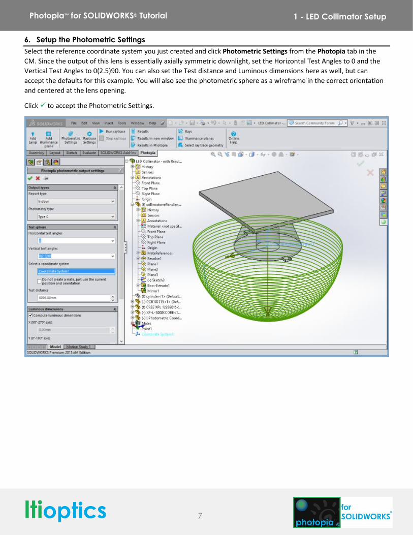
Click Insert > Reference Geometry > Coordinate System. Choose the point that was just inserted as the Origin for the
coordinate system. Then click in the Z axis selection box and select the top face of the Collimator PCB to orient the Z axis
upwards.
7
Photopia™ for SOLIDWORKS® Tutorial 1 - LED Collimator Setup
6. Setup the Photometric Settings
Select the reference coordinate system you just created and click Photometric Settings from the Photopia tab in the
CM. Since the output of this lens is essentially axially symmetric downlight, set the Horizontal Test Angles to 0 and the
Vertical Test Angles to 0(2.5)90. You can also set the Test distance and Luminous dimensions here as well, but can
accept the defaults for this example. You will also see the photometric sphere as a wireframe in the correct orientation
and centered at the lens opening.
Click to accept the Photometric Settings.
8
Photopia™ for SOLIDWORKS® Tutorial 1 - LED Collimator Setup
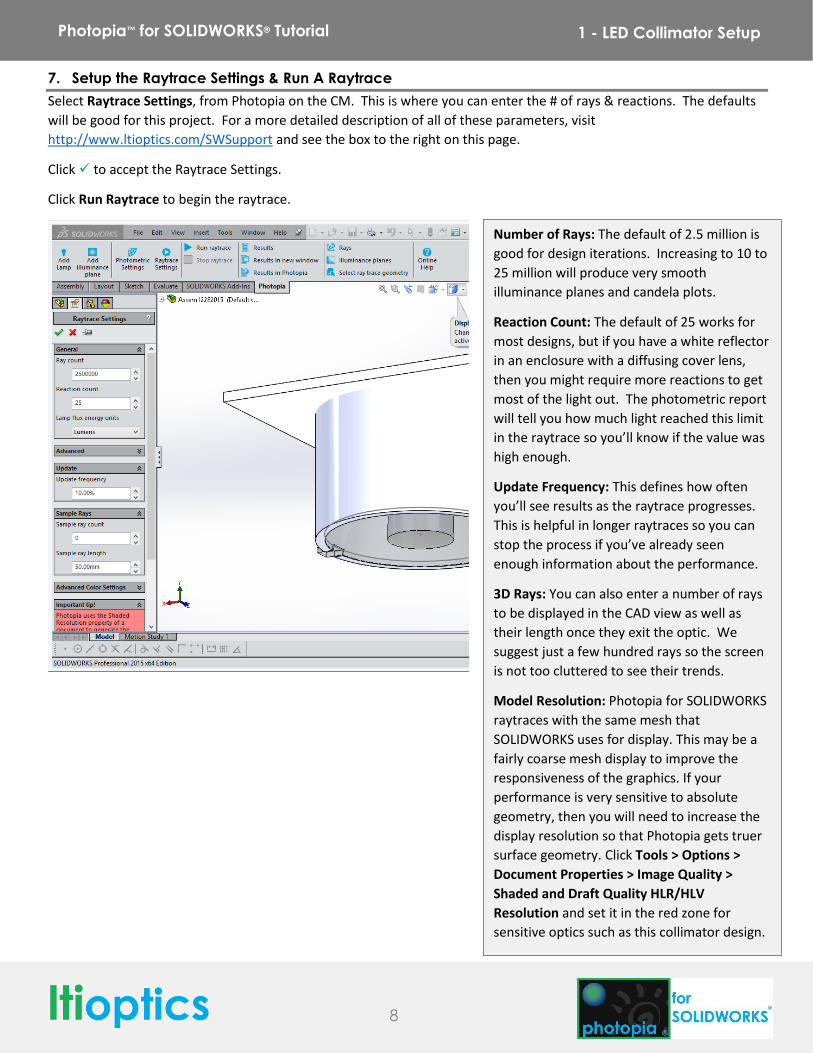
7. Setup the Raytrace Settings & Run A Raytrace
Select Raytrace Settings, from Photopia on the CM. This is where you can enter the # of rays & reactions. The defaults
will be good for this project. For a more detailed description of all of these parameters, visit
http://www.ltioptics.com/SWSupport and see the box to the right on this page.
Click to accept the Raytrace Settings.
Click Run Raytrace to begin the raytrace.
Number of Rays: The default of 2.5 million is
good for design iterations. Increasing to 10 to
25 million will produce very smooth
illuminance planes and candela plots.
Reaction Count: The default of 25 works for
most designs, but if you have a white reflector
in an enclosure with a diffusing cover lens,
then you might require more reactions to get
most of the light out. The photometric report
will tell you how much light reached this limit
in the raytrace so you’ll know if the value was
high enough.
Update Frequency: This defines how often
you’ll see results as the raytrace progresses.
This is helpful in longer raytraces so you can
stop the process if you’ve already seen
enough information about the performance.
3D Rays: You can also enter a number of rays
to be displayed in the CAD view as well as
their length once they exit the optic. We
suggest just a few hundred rays so the screen
is not too cluttered to see their trends.
Model Resolution: Photopia for SOLIDWORKS
raytraces with the same mesh that
SOLIDWORKS uses for display. This may be a
fairly coarse mesh display to improve the
responsiveness of the graphics. If your
performance is very sensitive to absolute
geometry, then you will need to increase the
display resolution so that Photopia gets truer
surface geometry. Click Tools > Options >
Document Properties > Image Quality >
Shaded and Draft Quality HLR/HLV
Resolution and set it in the red zone for
sensitive optics such as this collimator design.
9
Photopia™ for SOLIDWORKS® Tutorial 1 - LED Collimator Setup
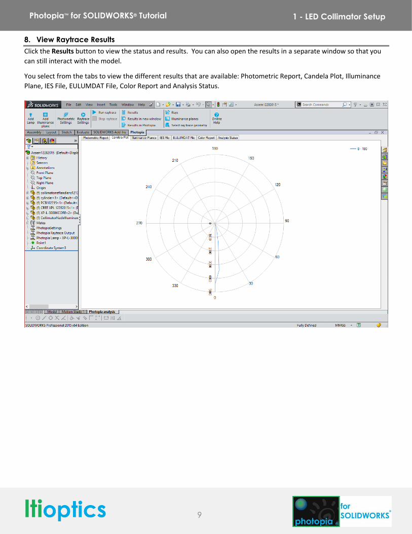
8. View Raytrace Results
Click the Results button to view the status and results. You can also open the results in a separate window so that you
can still interact with the model.
You select from the tabs to view the different results that are available: Photometric Report, Candela Plot, Illuminance
Plane, IES File, EULUMDAT File, Color Report and Analysis Status.
10
Photopia™ for SOLIDWORKS® Tutorial 1 - LED Collimator Setup
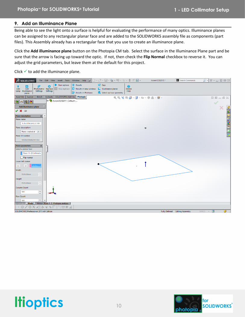
9. Add an Illuminance Plane
Being able to see the light onto a surface is helpful for evaluating the performance of many optics. Illuminance planes
can be assigned to any rectangular planar face and are added to the SOLIDWORKS assembly file as components (part
files). This Assembly already has a rectangular face that you use to create an illuminance plane.
Click the Add illuminance plane button on the Photopia CM tab. Select the surface in the Illuminance Plane part and be
sure that the arrow is facing up toward the optic. If not, then check the Flip Normal checkbox to reverse it. You can
adjust the grid parameters, but leave them at the default for this project.
Click to add the illuminance plane.
11
Photopia™ for SOLIDWORKS® Tutorial 1 - LED Collimator Setup
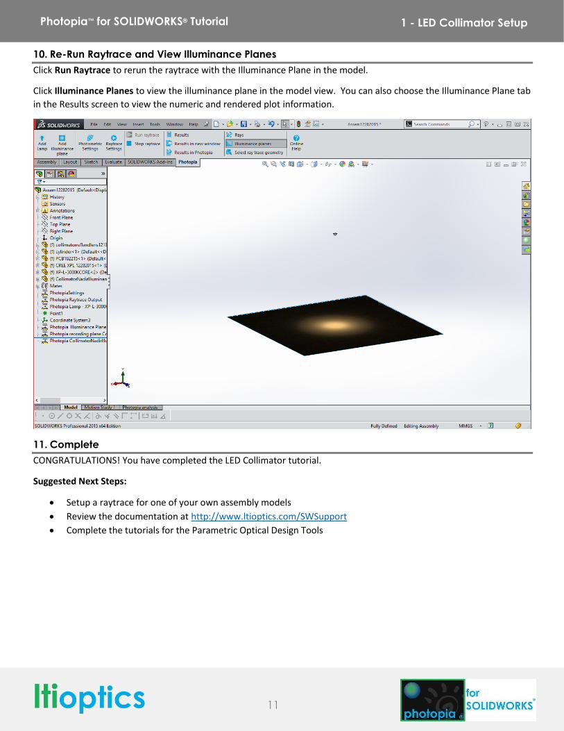
10. Re-Run Raytrace and View Illuminance Planes
Click Run Raytrace to rerun the raytrace with the Illuminance Plane in the model.
Click Illuminance Planes to view the illuminance plane in the model view. You can also choose the Illuminance Plane tab
in the Results screen to view the numeric and rendered plot information.
11. Complete
CONGRATULATIONS! You have completed the LED Collimator tutorial.
Suggested Next Steps:
Setup a raytrace for one of your own assembly models
Review the documentation at http://www.ltioptics.com/SWSupport
Complete the tutorials for the Parametric Optical Design Tools
Recommended