Before installing hoist, fill in the information below.
Model Number
Serial No.
Purchase Date
Voltage
Rated Load
RATED LOADS 1/4 TO 3 TONS 250 KG TO 3000 KG Follow all instructions and warning for inspecting, maintaining and operating this hoist.
The use of any hoist presents some risk of personal injury or property damage. That risk is greatly increased if proper instructions and warnings are not followed. Before using this hoist, each operator should become thoroughly familiar with all warnings, instructions and recommendations in this manual. Retain this manual for future reference and use.
Forward this manual to operator. Failure to operate equipment as directed in manual may cause injury.
ELECTRIC CHAIN HOIST
OPERATING, MAINTENANCE & PARTS MANUAL
P/N: 113535-60 (REV AD) April 2015

P/N: 113535-60 (REV AD) April 20152
FOREWORD This book contains important information to help you install, operate, maintain and service your new Electric Hoist. We recommend that you study its content thoroughly before putting your hoist into use. Then, through proper installation, application of correct operating procedures, and by practicing the recommended maintenance suggestions you will be assured maximum lifting service from the hoist.
Complete inspection, maintenance and overhaul service is available for CM Man Guard™ Electric Hoists at Authorized Repair Stations. All are staffed by qualified factory-trained service men; have authorized testing equipment; and stock a complete inventory of factory approved CM Man Guard replacement parts.
Complete replacement parts information is given in Section IX. It will likely be a long time before parts information is needed, therefore, after you completely familiarize yourself with operation and preventive maintenance procedures, we suggest that this instruction and parts manual be carefully filed for future reference.
Notice: Use only factory approved CM Man Guard replacement parts, available from Authorized Repair Stations or CM Man Guard Hoist Distributors.
The “Accident Prevention Manual for Industrial Operations’ (8th Edition) by the National Safety Council states:
“Employees who work near cranes or assist in hooking on or arranging loads should be instructed to keep out from under loads. Supervisors should watch closely to see that this rule is strictly followed.
From a safety standpoint, one factor is paramount: conduct all lifting operations in such a manner that if there were an equipment failure, no personnel would be injured. This means keep out from under raised loads!”
THE INFORMATION CONTAINED IN THIS MANUAL IS FOR INFORMATIONAL PURPOSES ONLY AND CM MAN GUARD HOISTS DOES NOT WARRANT OR OTHERWISE GUARANTEE (IMPLIEDLY OR EXPRESSLY) ANYTHING OTHER THAN THE COMPONENTS THAT CM MAN GUARD MANUFACTURES AND ASSUMES NO LEGAL RESPONSIBILITY (INCLUDING, BUT NOT LIMITED TO CONSEQUENTIAL DAMAGES) FOR INFORMATION CONTAINED IN THIS MANUAL.
INDEX Page
SECTION I GENERAL DESCRIPTION
Paragraph 1-1 General ...................................................................................................................................................... 3 Paragraph 1-2 Hoist Service Classification ....................................................................................................................... 3 Paragraph 1-3 Basic Construction .................................................................................................................................... 3 Paragraph 1-4 Differences Between Models and Sizes .................................................................................................... 4 Paragraph 1-5 MAN GUARD Overload Clutch .................................................................................................................. 4
SECTION II INSTALLATION
Paragraph 2-1 General ...................................................................................................................................................... 4 Paragraph 2-2 Installation .................................................................................................................................................. 4 Paragraph 2-3 Pre-Installation Checks .............................................................................................................................. 4 Paragraph 2-4 Connecting Hoist to Electrical Service ...................................................................................................... 5
SECTION III OPERATION
Paragraph 3-1 General ...................................................................................................................................................... 6 Paragraph 3-2 Operating Hoist ......................................................................................................................................... 6 Paragraph 3-3 Pulling and Rotating Hoist and Load ......................................................................................................... 6 Paragraph 3-4 Upper and Lower Limit ............................................................................................................................... 6 Paragraph 3-4A Upper and Lower Limit Stops (Paddle Limit) ............................................................................................. 6 Paragraph 3-5 MAN GUARD Overload Clutch Operations ............................................................................................... 6 Paragraph 3-6 Operating Precautions ............................................................................................................................... 6
SECTION IV LUBRICATION
Paragraph 4-1 General ...................................................................................................................................................... 7 Paragraph 4-2 Change Gear Case Oil ............................................................................................................................... 7 Paragraph 4-3 Lubricate Load Chain ................................................................................................................................ 7 Paragraph 4-4 Lubricate Upper Hook and Lower Block Assembly .................................................................................. 8 Paragraph 4-5 Lubricate Limit Lever Control Shaft and Gears ......................................................................................... 8
SECTION V MAINTENANCE
Paragraph 5-1 General ...................................................................................................................................................... 8 Paragraph 5-2 Thirty-Day Inspection ................................................................................................................................ 8 Paragraph 5-3 Six-Month Inspection .............................................................................................................................. 10 Paragraph 5-4 Inspection 5000 Hour or Five Year .......................................................................................................... 10
SECTION VI TROUBLE SHOOTING CHART ................................................................................................................................ 11–12
SECTION VII DISASSEMBLY AND REASSEMBLY
Paragraph 7-1 Rebuild of Load Brake and Overload Clutch Assembly .......................................................................... 13 Paragraph 7-1A Overload Clutch without Load Brake ....................................................................................................... 14 Paragraph 7-2 Brake Adjustment .................................................................................................................................... 15 Paragraph 7-3 Testing Hoist ............................................................................................................................................ 18 Paragraph 7-13 Test Procedure For Checking Operation of Overload Clutch .................................................................. 18
SECTION IX REPLACEMENT PARTS ................................................................................................................................................. 19
Notice: Information contained in this book is subject to change without notice.

P/N: 113535-60 (REV AD) April 20153
SECTION I - GENERAL DESCRIPTION
1-1. GENERAL.CM Man Guard Portable Electric Hoists are precision built chain type hoists ranging in five rated load sizes from 1/4 ton through 3 tons with various lifting speeds and electrical power supplies. In addition to the capacities, there are model variations with hook or lug type suspension, and single or variable speed.
1-2. HOIST SERVICE CLASSIFICATIONa. CM Man Guard electric hoists at the time of manufacture
comply with our interpretation of applicable sections of ANSI B30.16 “Overhead Hoists”, National Electric Code ANSI/ NFPA 70 and Occupational Safety and Health Act, 1992.
b. OSHA places the burden of compliance for hoist installations on the user. The user must install the equipment in accordance with the National Electric Code ANSI/NFPA 70 as well as other federal, state and local regulations which apply to the installation and application in your particular area.
c. These hoists meet ANSI/ASME HST-1M “Performance Standard for Electric Chain Hoists” hoist duty class ratings as outlined in the sales bulletin.
Equipment covered herein is not designed or suitable as a power source for lifting or lowering persons. Do not use as an elevator.
1-3. BASIC CONSTRUCTION. All sizes and models of these CM Man Guard Electric Hoists are of the same basic designs, having many common and interchangeable parts. They consist primarily of an aluminum alloy frame and gear case cover which houses the gear train. An electric driving motor and external motor brake are mounted on the rear of the frame, Electrical control components are mounted on front of the gear case cover and encased by aluminum alloy end cover. An upper hook or lug bracket for suspending the hoist is attached to the top of the frame. A high strength low alloy coil load chain with lower block assembly is employed to raise and lower loads. Hoist operation is controlled by a pendant push button station.
Figure 1-1. Typical CM Man Guard Electric Hoist

P/N: 113535-60 (REV AD) April 20154
1-4. DIFFERENCES BETWEEN MODELS AND SIZES.
The main differences between hoist models are in the service classification, type of load chain and the suspension employed. These are described in paragraphs (a) through (c), below. The differences between sizes of hoists are in the number of gear reductions used and the reeving of the load chain. Two-reduction gearing is used for 1/4 through 1/2 ton rated load hoists; three-reduction gearing for 1, 2 and 3 ton rated hoists. On 1/4 through 1 ton rated load hoists, the load chain is single reeved (one part of chain); on 2 ton rated loads, the chain is double reeved (two parts of chain); on three ton rated loads, the chain is triple reeved (three parts of chain).
d. Coil type chain is full-flexing electric welded link chain. It is especially designed for use with your CM Electric Hoists and only factory approved chain of the correct size, pitch, hardness, and strength can be used with these hoists.
e. Suspension differences include a conventional hook type mounting and a lug type mounting. Hook suspension allows portability permitting hoist to be easily moved from job to job. Lug suspension permits hoist to be rigidly mounted to overhead structure or attached to CM Man Guard Rigid Mount Trolleys, affording unusual headroom advantage.
1-5. MAN GUARD OVERLOAD CLUTCH. CM Electric Hoists having a MAN GUARD label are equipped with an overload clutch that is designed to help guard against excessive overloads. It is a cone-friction clutch that connects the first reduction gear to the clutch pinion shaft. A belleville disc spring provides clutch pressure between the gear and its cone shaped gear center. An excessive overload causes the gear to rotate without turning the gear center and pinion shaft. See paragraph 3-5 for operation.
The man guard overload clutch is a protective device that will permit operation of your hoist within its rated load and will prevent lifting of excessive overloads which can cause permanent deformation or weakening of a properly maintained hoist and/or its suspension.
SECTION II - INSTALLATION
2-1. GENERAL. CM Man Guard Electric Hoists are completely lubricated and load tested under their own power before being shipped from the factory. To place hoist in service, attach to suitable overhead suspension (par. 2-2) in area to be used; make pre-installation check (par. 2-3); and connect to the proper power supply (par 2-4).
2-2. INSTALLATION.
NOTICELubricate load chain before operating hoist. See paragraph 4.3
a. On hook suspended hoists, select a suitable overhead support in area hoist is to be used (one capable of holding weight of hoist and its rated load) and hang up hoist. Be certain upper hook is firmly seated in center of hook saddle. Upper hook is equipped with a spring type hook latch; it may be necessary to remove latch to attach hook to support. Replace latch after hoist is installed.
b. On lug suspended hoists, select a suitable overhead support in area hoist is to be used (one capable of holding weight of hoist and its rated load). Mount hoist using through bolts, of appropriate size, to fit mounting holes in suspension lug at top of hoist frame. (See table below.) The structure used to suspend hoist must be of sufficient strength to withstand reasonable forces to which hoist and support may be subjected. Hoist must be aligned with load to avoid side pulls.
c. On lug suspended hoists, the suspension lug is factory oriented to cross mount the hoist. This is the recommended orientation. To rotate the lug 90º for parallel mounting, follow instructions below:
1. On 1/4 through 1 ton hoists, remove the two screws securing the anti-rotation bracket and remove the bracket. Rotate the suspension lug in 90º increments. Reinstall the anti-rotation bracket and secure with two screws and lock washers.
2. On 2 ton hoists, remove hex socket head screw in lower lock plate. Remove lower lock plate. Rotate suspension lug to selected position and replace lock plate and hex socket head screw.
3. On 3 ton hoists, the hanger bracket must first be removed from the hoist to provide access to suspension nut. With bolt removed lift lug from hanger and reposition as desired. The lug is located and prevented from turning by integral lugs on adjacent surfaces of the lug and the hanger. Reinstall suspension bolt, spherical washers and nut. Align hole in nut and suspension bolt. Reassemble hanger bracket to hoist.
d. On rigid mount trolley suspended hoists, the trolley side plates must be properly spaced so trolley will fit I-beam on which hoist will operate. Adjustment for various I-beam sizes is accomplished by rearrangement of spacer washers on through bolts which connect trolley side plates to suspension lug on hoist. Refer to instruction sheet furnished with CM Man Guard Rigid Mount Trolleys for complete instructions.
SUSPENSION LUG BOLT SIZES AND SPACING
HoistRated Load
(tons)
Bolt Diameter
(in)
DistanceBetween Holes
(in)
1/4, 1/2 &1 5/8 3-1/8
2 1 5
3 1-1/4 6
2-3. PRE-INSTALLATION CHECK.
CHECK OIL LEVEL (FIG. 4-1).
The gear case has been filled with oil, to the proper level at the factory. However, the oil level should be checked before hoist is operated. Remove pipe plug from oil filler on side of hoist frame. Replace with supplied oil hole cover. Check oil level by removing oil level plug (side of frame). Observe if oil level is even with bottom of tapped hole. If it is not, add oil, as specified in paragraph 4-2c. Also check load chain. Be sure it is properly lubricated. See para. 4-3.
CHECK LIMIT STOPS:
Paddle limit equipped. Make sure the actuator on the tail chain side is securely connected to the proper link. (See chart on page 30). On single part hoists, make sure steel actuator is connected to the first chain link above the lower block. Multiple part reeved hoists do not have an actuator on the lower block side.

P/N: 113535-60 (REV AD) April 20155
2-4. CONNECTING HOIST TO ELECTRICAL SERVICE.
a. All hoists are equipped with a flexible power cable extending from the hoist. A grounding type male plug or permanent connection in an outlet box may be used for connecting hoist to power supply. See table (fig. 2-1) for branch circuit conductor sizes.
H.P. Power Supply
AWG Wire Size
#16 #14 #12 #10 #8 #6
1/4
115-1-60 80 130 210 330
230-1-60 230 330 835
230-3-60 465 740 1180
460-3-60 1440 2390
1/2
115-1-60 45 75 120 190 310 490
230-1-60 195 305 490 775 1235
230-3-60 280 450 715 1135
460-3-60 860 1440
1
115-1-60 * 45 75 120 190 300
230-1-60 120 190 300 475 720
230-3-60 180 290 460 730
460, 575-3-60 560 900
2½230-3-60 60 100 150 250
460, 60 260 420
*Do not use
Figure 2-1.
Branch Circuit Conductor Size. Maximum length in feet for wire size based on horsepower and power supply. Wire size for entire length of branch circuit and permanent wiring to main feeder. Power supply measured at hoist, while running and with normal load, must not vary more than ±5% of voltage on motor nameplate.
b. Follow local & National Electrical Codes when providing electrical service to hoist. Connect power wires in accordance with appropriate wiring diagram. Power supply must be the same voltage, frequency and phase as specified on the hoist nameplate.
The green wire provided in the power supply cable is a grounding wire and must be connected to a proper ground. (Follow local code requirements and/or National Electrical Code Article 250).
c. Dual voltage hoists with reconnectable 230/460 volts, 3 phase, 60 hertz are (unless otherwise specified on customer’s order) shipped from factory pre-connected for operation on 230 volts. If hoist is to be operated on 460 volts convert wiring by changing connections on terminal board. With hoist disconnected from power source, remove electrical compartment cover and reconnect terminal board leads. Refer to Wiring Diagram.
d. Dual voltage hoists with reconnectable 115/230 volts, 1 phase, 60 hertz are (unless otherwise specified on customer’s order) shipped from factory pre-connected for operation on 115 volts. If hoists are to be operated on 230 volts convert wiring by changing connections on terminal board. With hoist disconnected from power source, remove electrical compartment cover and reconnect terminal board leads. Also refer to Wiring Diagram.
On electrically operated hoists it is possible to have "Reverse Phasing" causing the lower block to raise when the down button is depressed. When this condition exists, the block operated limit switches will not function properly. Serious damage to the hoist can occur with resulting hazard to operator and load. Hoists must be properly phased each time they are installed or moved to a new power source, or when service is performed on mainline (power source).

P/N: 113535-60 (REV AD) April 20156
SECTION III - OPERATION
3-1. GENERAL. Operation of CM Man Guard Electric Hoists are controlled by a push button station suspended from the hoist electrical compartment. The station has a built-in mechanical interlock to prevent depressing both buttons simultaneously.
3-2. OPERATING HOIST.a. Depress push button marked “h” to raise load.
b. Depress push button marked “i” to lower loads.
c. Jogging the push buttons will give “hairline” load movement. The quickness of the depressing motion will determine the amount of movement. Excessive use of this “jogging” feature will cause premature burning of contact points, motor overheating, and rapid motor brake wear.
3-3. PULLING AND ROTATING HOIST AND LOAD.a. The push button station conductor cable has a built-in strain
cable suitable for pulling trolley suspended hoists when not loaded. Do not use for pulling bridge cranes. Push on load or load chain or use a hand geared or motor driven type trolley to traverse loaded hoists.
b. To rotate hoist and load, push on one corner of load. The lower hook will pivot through 360 degrees to permit load to be swung to the desired position. The upper hook (hook suspension models) is also designed to rotate so that side pulls will swing hoist to face load, thus reducing side thrust.
11925A
Figure 3-1. Limit Switch Illustration
3-4 UPPER AND LOWER LIMITS.CM Man Guard Electric Hoists are equipped with a paddle type limit switch, operated by the lower block in the up direction and an actuator attached to the chain in the lowering direction.
3-4A. UPPER AND LOWER LIMIT STOPS (PADDLE LIMIT).
A lower block and chain operated limit stop is provided to guard against over-travel of load in either raising or lowering direction, which can cause damage to hoist. When highest position is reached a limit actuator on the load chain, above the lower block, trips the limit lever (fig. 3-1). When lowest position is reached, a limit actuator on the tail end of load chain trips the limit lever (fig. 3-1). The limit lever is connected to a limit switch that automatically stops the hoist motor. This is intended as a safety device and is not to be used on a routine basis to stop travel of lower block or shut off hoist.
3-5. OVERLOAD CLUTCH OPERATION.The overload clutch is factory preset at assembly so that the hoist will lift its full rated load but will refuse to lift overloads within a range of 150 percent rated load to 200 percent rated load. If the load to be lifted exceeds the clutch factory setting, the motor will continue to run and will rotate the clutch gear without lifting the load. Whenever this occurs, immediately release the “h” push button to prevent overheating of the clutch friction surfaces and motor, and reduce the load to rated hoist capacity. Should it be impractical to reduce the load, replace the hoist with one of suitable rated capacity.
NOTE: Always know the load to be lifted. CM Hoists does not recommend lifting loads greater than the rated load of your hoist.
3-6. OPERATING PRECAUTIONS.
Equipment covered herein is not designed or suitable as a power source for lifting or lowering persons. Do not use as an elevator.
Safe operation of an overhead hoist is the operator’s responsibility. The following are some basic rules that can make an operator aware of dangerous practices to avoid and precautions to take for his own safety and the safety of others. Observance of these rules in addition to frequent examinations and periodic inspection of the equipment may save injury to personnel and damage to equipment.
a. DO read ANSI B30.16 Safety Standard for Overhead Hoists and the Operation, Service and Parts Manual
b. DO be familiar with hoist operating controls, procedures and warnings.
c. DO make sure hook travel is in the same direction as shown on controls.
d. DO make sure hoist limit switches function properly.
e. DO maintain firm footing when operating hoist.
f. DO make sure that load slings or other approved single attachments are properly sized and seated in the hook saddle.
g. DO make sure that the hook latch, is closed and not supporting any part of the load.
h. DO make sure that load is free to move and will clear all obstructions.
i. DO take up slack carefully, check load balance, lift a few inches and check load holding action before continuing.
j. DO avoid swinging of load or load hook.
k. DO make sure that all persons stay clear of the suspended load.
l. DO warn personnel of an approaching load.
m. DO protect load chain from weld splatter or other damaging contaminants.
n. DO promptly report any malfunction, unusual performance, or damage of the hoist.
o. DO inspect hoist regularly, replace damaged or worn parts, and keep appropriate records of maintenance.
p. DO use the hoist manufacturer’s recommended parts when repairing a hoist.
q. DO use hook latches wherever possible.
r. DO apply lubricant to load chain as recommended.
s. DO NOT lift more than rated load.
t. DO NOT use the hoist load limiting device to measure the load.
u. DO NOT use damaged hoist or hoist that is not working correctly.

P/N: 113535-60 (REV AD) April 20157
v. DO NOT use the hoist with twisted, kinked, damaged or worn chain.
w. DO NOT lift a load unless chain is properly seated in chain wheel(s) or sprocket(s).
x. DO NOT use load chain as a sling or wrap chain around the load.
y. DO NOT lift a load if any binding prevents equal loading on all supporting chains.
z. DO NOT apply the load to the tip of the hook.
aa. DO NOT operate unless load is centered under hoist.
ab. DO NOT allow your attention to be diverted from operating the hoist.
ac. DO NOT operate the hoist beyond limits of load chain travel.
ad. DO NOT use limit switches as routine operating stops. They are emergency devices only.
ae. DO NOT use hoist to lift, support or transport people.
af. DO NOT lift loads over people.
ag. DO NOT leave a suspended load unattended unless specific precautions have been taken.
ah. DO NOT allow sharp contact between two hoists or between hoist and obstructions.
ai. DO NOT allow the chain or hook to be used as a ground for welding.
aj. DO NOT allow the chain or hook to be touched by a live welding electrode.
ak. DO NOT remove or obscure the warnings on the hoist.
al. DO NOT adjust or repair a hoist unless qualified to perform hoist maintenance.
am. DO NOT attempt to lengthen the load chain or repair damaged load chain.
an. DO NOT allow personnel not physically fit or properly qualified to operate the hoist.
ao. DO NOT operate hoist unless upper and lower limit switch stops are operating properly.
ap. DO always be sure there is no twist in coil load chain. On 2 & 3 ton coil chain hoists, check to see that lower block is not capsized between strands of chain.
aq. DO avoid operating hoist when hook is not centered under hoist. Be sure that hoist trolley or other support mechanism is correctly positioned for handling the load before lifting.
ar. DO operate hoist within recommended duty cycle and do not “jog” unnecessarily.
as. DO conduct regular visual inspections for signs of damage or wear.
at. DO NOT operate hoist with hooks that have opened up. See Figures 5-5 and 5-6.
au. DO provide supporting structure or anchoring means that has a load rating at least equal to that of the hoist.
av. DO NOT use hoists in locations that will not allow operator movement to be free of the load.
aw. DO when starting to lift or pull, move the load a few inches at which time the hoist should be checked for proper load holding action. The operation shall be continued only after the operator is assured that the hoist is operating properly.
ax. DO NOT leave a loaded hoist unattended at the end of a work shift or for extended periods during the work shift. Where operations are such that this condition cannot be avoided the operator must be assured that the condition does not create a hazard to personnel or property.
ay. DO use common sense and best judgement whenever operating a hoist. Observe American National Standard Safety standard, ANSI B30.16, latest issue.
SECTION IV - LUBRICATION
4-1. GENERAL. The lubrication services outlined in paragraphs 4-2 through 4-5 should be performed at regular intervals to maintain top hoist performance and insure long life. The frequency for lubrication services will depend on the type of hoisting service that hoist is subjected to and should coincide with periodic preventive maintenance inspection. See Section V-Maintenance.
4-2. CHANGE GEAR CASE OIL (FIG. 4-1).a. Remove drain plug from bottom of hoist frame and drain
oil from gear case. Replace plug.
b. Remove oil level plug from side of hoist.
c. Refill gearcase through oil filler to proper level (bottom of oil level plug hole) using Automatic Transmission Fluid - DEXRON Type. This is an all-weather oil available from all major oil companies. 1-1/2 pints of oil are required.
d. Reinstall oil level plug and breather.
4-3. LUBRICATE LOAD CHAIN. A small amount of lubricant will greatly increase load chain life, therefore, chain should not be allowed to run without lubricant. Chain should be cleaned and lubricated as directed in paragraph a below. User should set up a regular schedule for chain lubrication after observing operating conditions for a few days. Use Bar and Chain Oil (LUBRIPLATE or equal) on load chain.
10077L
Figure 4-1. Location of Oil Filler and Plugs
a. Coil Chain. Under ordinary conditions only weekly attention will be necessary. Under hot and dirty conditions it may be necessary to clean chain at least once a day and lubricate it several times between cleanings. Thoroughly clean chain with an oil solvent and re-lubricate by coating it lightly with oil. Make sure that lubricant coats wear surfaces between links. Zinc plated load chain should be cleaned and lubricated daily.

P/N: 113535-60 (REV AD) April 20158
4-4. LUBRICATE UPPER HOOK AND LOWER BLOCK ASSEMBLY.
a. Apply a few drops of Bar and Chain Oil on shank of upper hook where it enters frame.
b. Apply a few drops of Bar and Chain Oil on shank of lower hook where it enters lower block. Hook rotation bearing may be removed for cleaning and re-lubricating if necessary. See section 7-5.
c. On lower block assemblies of 2 and 3 ton capacity hoists, also apply heavy duty lithium soap grease with EP additives through pressure fitting in end of sprocket pin to lubricate bearing in chain sprocket.
d. On 3 ton model lubricate sprocket in hanger bracket with a few drops of Bar and Chain Oil in hole provided in center of sprocket hub.
4-5. LUBRICATE LIMIT LEVER CONTROL SHAFT AND GEARS.
Apply a few drops of Bar and Chain Oil on limit lever shaft at bearing points.
Before performing any internal work on hoist, be certain power is shut off. Lock main service switch in the open position.
SECTION V - MAINTENANCE
5-1. GENERAL. Preventive maintenance services required on CM Man Guard Electric Hoists are for the most part, simple periodic inspection procedures to determine condition of hoist components. Below are suggested inspection procedures, based on daily average hoist usage.
5-2. THIRTY-DAY INSPECTION. Hoist may be left suspended.
A. INSPECT LOAD CHAIN.
LOAD CHAIN
Chain should feed smoothly into and away from the hoist or hook block. If chain binds, jumps or is noisy, first clean and lubricate it (see below). If trouble persists, inspect chain and mating parts for wear, distortion or other damage.
CHAIN INSPECTION
First clean chain with a non-caustic/non-acid type solvent and make a link by link inspection for nicks, gouges, twisted links, weld splatter, corrosion pits, striations (minute parallel lines), cracks in weld areas, wear and stretching. Chain with any one of these defects must be replaced.
Figure 15. Chain Wear Areas
Slack the portion if the chain that normally passes over the liftwheel. Examine the interlink area for the point of maximum wear (polishing, see Figure 15). Measure and record the stock diameter at this point of the link. Then measure stock diameter in the same area on a link that does not pass over the liftwheel (use the link adjacent to the
loose end link for this purpose). Compare these two measurements. If the stock diameter of the worn link is 0.005 inches (0.254 mm), or more, less than the stock diameter of the unworn link, the chain must be replaced. On double reeved units, repeat this examination of the chain that passes through the hook block.
Also check chain for stretch using a vernier caliper as shown in Figure 16. Select an unused, unstretched section of chain (usually at the loose end) and measure and record the length over 11 chain links (pitches). Measure and record the same length on a worn section of the chain. Obtain the amount of stretch and wear by subtracting the measurement of the worn section. If the result (amount of stretch and wear) is greater than 0.145 inch (3.7mm), the chain must be replaced.
Figure 16. Chain Inspection
Use only a “Knife-edge” caliper to eliminate possibility of false reading by not measuring full pitch length. Note that worn chain can be an indication of worn hoist components. For this reason, the hoist’s chain guide, hook block and liftwheel should be examined for wear and replaced as necessary when replacing worn chain.
Also, these chains are specially heat treated and hardened and should never be repaired
Figure 17. Chain Embossing Use only Star (*) grade load chain and original replacement parts. Use of other chain and parts may be dangerous and voids factory warranty.
Chain Embossing Use only Star (*) grade load chain and original replacement parts. Use of other chain and parts may be dangerous and voids factory warranty.
Use of commercial or other manufactures’ chain and parts to repair Lodestar Hoists may cause load loss.
TO AVOID INJURY:
Use only factory supplied replacement load chain and parts. Chain and parts may look alike, but factory original chain and parts are made of specific materials or processed to achieve specific properties. See Figure 17.
IMPORTANT: Do not use replaced chain for other purposes such as lifting or pulling. Load chain may break suddenly without visual deformation. For this reason, cut replaced chain into short lengths to prevent use after disposal.
P/N: 113535-60 (REV AD) April 20159
NOTICEUse one or two "C" links to orient chain for chain anchor screw. Position first link of new chain to be flat against hoist housing without twisting the chain.
On 2 ton double reeved models, also connect opposite end of chain (from lower block) to load chain anchor inside of frame. On 3 ton triple reeved models, the opposite end of the chain is attached to the lower block connecting link.
B. INSPECT LOWER BLOCK.
Hooks shall be removed from service if damage such as the following is visible and shall only be returned to service when approved by a qualified person:
1. Missing or illegible hook manufacturer's identification or secondary manufacturer's identification.
2. Missing or illegible rated load identification.
3. Excessive pitting or corrosion.
4. Cracks, nicks, or gouges.
5. Wear – any wear exceeding 10% (or as recommended by the manufacturer) of the original section dimension of the hook or its load pin.
6. Deformation – any visibly apparent bend or twist from the plane of the unbent hook.
7. Throat Opening – any distortion causing an increase in throat opening of 5% not to exceed 1/4" in. (6 mm) (or as recommended by the manufacturer).
8. Inability to Lock – any self-locking hook that does not lock.
9. Inoperative Latch (if provided) – any damaged latch or malfunctioning latch that does not close the hook's throat.
10. Damaged, missing or malfunctioning hook attachment and securing means.
HoistRated Load
(tons)
Hook Throat Opening
NormalOpening
1/4 & 1/2 1-1/8
1 1-1/4
2 1-3/8
3 1-1/2
Figure 5-5. Lower Hook Opening (Shown with latch removed for clarity.)
Hooks, upper or lower, damaged from chemicals, deformation or cracks or having more than 15 percent in excess of normal throat opening or more that 10 degrees twist from the plane of the unbent hook, or opened, allowing the hook latch to bypass hook tip must be replaced.
Any hook that is twisted or has excessive throat opening indicates abuse or overloading of the hoist. Other load bearing components of the hoist should be inspected for damage. (See Section V. Par. 5-2. d. (2) below).
Do not assume that load chain is safe because it measures below replacement points given herein. Other factors, such as those mentioned in visual checks above, may render chain unsafe or ready for replacement long before elongation replacement is necessary.
To avoid serious personal injury from a dropped load caused by chain breakage, when replacing coil load chain, use only factory approved chain conforming to CM Man Guard hoist specifications for material, hardness, strength and link dimensions. Chain not conforming to factory Specifications may be dangerous as it will not fit in the load sprocket and chain guide correctly, causing serious internal damage to hoist and it will wear prematurely, deform and eventually break.
REMOVING AND REPLACING COIL LOAD CHAIN.
a. Replacement Coil load chain is installed by attaching it to tail end of old chain, after disconnecting old chain from side of hoist frame and removing limit actuator. New chain is then run into hoist as old chain is run out. Use open “C” links, figures 5-3 and 5-4, for attaching chains. Links must be identical in size to hoist chain - 1/4" wire size with .745" pitch length for 1/4 through 1/2 ton models, 5/16" wire size with .858" pitch for 1 through 3 ton models. Be certain that all welds on links of replacement chain face away from center of load sprocket.
Figure 5-3. Open "C" Link for Removing and Installing Coil Load Chain
Figure 5-4. Installing Coil Load Chain Using Two "C" Links (1/4, 1/2 & 1 ton hoists)
b. Remove lower block assembly and actuator from old chain and attach them to replacement chain at end which was just run through hoist. Install limit actuator (as noted below) on other end of chain and anchor chain to side of hoist frame.

P/N: 113535-60 (REV AD) April 201510
HoistRated Load
(tons)
Hook Throat Opening
NormalOpening
1/4 & 1/2 1-1/8
1 1-1/4
2 1-3/8
3 1-1/2
Figure 5-6. Upper Hook Opening (Shown with latch removed for clarity.)
11. Thread wear, damage, or corrosion.
12. Evidence of excessive heat exposure or unauthorized welding.
13. Evidence of unauthorized alterations such as drilling, machining, grinding or other modifications.
14. On lug suspended models, check condition of suspension lug. Replace lug if damaged or cracked. Check to see that lock plate is in place on lug and screw holding it is tight. (All capacities see figure 7-20).
15. On 2-ton hoists, check to see that upper lock plate securing hook or lug bushing is in place and screws holding it are tight. Lubricate hook shank.
16. Check hook latch. Replace damaged or broken parts.
17. Inspect threaded upper suspension bushing. Verify keeper is in place against flat of suspension bushing, and securing screw and lock washer are in place and tight.
C. INSPECT MOTOR, FRAME AND ELECTRICAL COMPARTMENT COVER.
1. Check to see that bolts securing motor to frame are tight. Also check for any visible damage to motor, such as a cracked end bell or dented stator housing. Replace damaged parts.
2. Check hoist frame for signs of visible damage. If frame shows evidence of fracture, the hoist should be disassembled and inspected for further signs of damage from possible overloading. Replace damaged parts.
3. Check for possible damage to electrical compartment cover. Be sure screws holding cover are tight.
D. CHECK OIL LEVEL.
Remove oil level plug (fig. 4-1). If oil level is not even with bottom of tapped hole, add Automatic Transmission Fluid, DEXRON Type, to bring to proper level.
5-3. SIX-MONTH INSPECTION OR 500-750 HOURS OF OPERATION.
Hoist may be left suspended. Same as thirty day inspection plus the following:
a. Inspect Electrical Controls. Shut off power supply to hoist and remove electrical compartment cover from hoist. Use caution as some covers contain counterweights.
1. Check all wiring and terminals. Insulation should be sound and terminals securely crimped to wires. Terminal screws should be tight and plug-type terminals completely mated. Replace terminals or wires as necessary.
2. Check control circuit transformer for evidence of overheating. Replace if necessary.
3. Check limit switch to see that wires are securely attached and mounting screws are tight.
4. Check contactor solenoid coils and replace coils if they show evidence of overheating.
5. Check control cable wire strain reliever to see that it is in good condition and securely attached to gear case cover. Replace rubber strain reliever grommets if damaged.
b. Change Gear Case Oil. See Section IV, paragraph 4-2.
c. Relubricate Load Chain. See Section IV, paragraph 4-3.
d. Lubricate Upper Hook and Lower Block. See Section IV, paragraph 4-4.
5-4. INSPECTION: 5000 HOURS “ON” TIME OR 5 YEARS ELAPSED TIME.
Hoist must be removed from overhead suspension.
a. Disassemble Hoist into Subassemblies. See CM Repair Center.
b. Motor shaft oil seal, sprocket shaft bearing, seal and all gaskets should be replaced.
c. Inspect Load Brake and Overload Clutch. Disassemble load brake (if equipped) and clutch assembly as outlined in paragraph 7-4. Friction discs should be discarded and replaced with new discs. Check load brake friction surfaces on flange, ratchet assembly and gear clutch cone. Replace parts if badly scored or worn. Check condition of pawl and ratchet assembly. If pawl, ratchet teeth or pawl spring are broken, damaged or badly worn, replace complete assembly. Check contact faces of load brake cam and gear clutch cone. Brake gear and pinion teeth should be inspected for wear or broken teeth. Clean parts thoroughly with an oil solvent before reassembly.
NOTE: The overload clutch assembly should not be disassembled as it is preset at the factory to provide proper clutch pressure for a specific hoist capacity range. If there is evidence of the clutch slipping or wear or damage to the clutch components, the complete clutch assembly should be replaced or sent to an authorized CM Man Guard Hoist Repair Station to be rebuilt and properly adjusted to factory specifications.
d. Inspect Sprocket and Intermediate Gears.
1. On 1 through 3 ton hoists, check condition of gear teeth on intermediate gear and pinion shaft assembly. Replace worn or damaged parts.
2. Check condition of pockets on chain sprocket (all capacities). Replace worn or damaged parts.
e. Inspect Motor Brake. Check braking surfaces for wear and scoring. Replace badly worn or scored parts. Check spring studs and guide pins to make sure they are not bent or loose. Check coil shock mounts for deterioration and damage. Check air gap adjustment. (See 7-11c)
f. Reassemble and Test Hoist. Reassemble hoist from subassemblies following procedure outlined in paragraph 7-11. After assembly is complete, test hoist as outlined in paragraphs 7-12 and 7-13.

P/N: 113535-60 (REV AD) April 201511
SECTION VI - TROUBLE SHOOTING
TROUBLE PROBABLE CASE REMEDY
6-1. Hoist Will Not Operate. a. No power to hoist. a. Check switches, circuit breakers and connections in power supply lines. Check power collectors.
b. Wrong voltage. b. Check voltage required on motor data plate against power supply.
c. No control voltage. c. Check transformer fuse. If blown, check for grounding and/or short in the pushbutton station. Check the transformer coil for signs of overheating. Replace transformer if burned out. Verify the transformer secondary is the same voltage as the coils to which it is connected.
d. Loose or broken wire connections in hoist electrical system.
d. Shut off power supply, remove electrical cover from hoist and check wiring connections Also check connections in push button station and limit switches.
e. Contactor assembly not functioning. e. Check for burned out solenoid coil. See that the necessary jumper wires are properly installed.
f. Starting switch burned out (single phase motor).
f. Replace burned out parts.
g. Motor burned out. g. Replace motor. On single-phase motors the starting switch may be burned out.
6-2. Hook Moves in Wrong Direction.
a. Reverse phasing on three-phase hoists. a. Interchange any two of the three power supply line leads. Do not change green ground lead. Refer to Section II, par. 2-4.
b. Hoist wired wrong. b. Check wiring connections with appropriate wiring diagram.
c. Starting switch not working correctly (single phase motor).
c. Check for correct starting switch part number and function. Replace if necessary.
6-3. Hook Will Raise But Not Lower.
a. "DOWN" electrical circuit open a. Check for loose connections. See that necessary jumper wires are properly installed on contactor. Check limit switch condition and electrical connections.
b. Contactor assembly not functioning. b. See that necessary jumper wires are properly installed. Verify that the contactor armatures are free to move. If binding occurs replace contactor. Check for burned out contactor coils.
c. Push Button Inoperative. c. Check push button contacts and wires.
d. Load Brake locked up and overload clutch slipping.
d. Consult Authorized CM Man Guard Hoist Repair Station.
6-4. Hook Will Lower But Not Raise.
(continues on next page)
a. Excessive load, causing overload clutch to slip.
a. Reduce loading to rated load of hoist, as shown on nameplate.
b. Overload clutch out of adjustment. b. Test hoist and replace clutch if hoist will not lift rated load.
c. "UP" electrical circuit open. c. Check for loose connections. See that necessary jumper wires are properly installed on contactor. Check limit switch condition and electrical connections.

P/N: 113535-60 (REV AD) April 201512
SECTION VI - TROUBLE SHOOTING
TROUBLE PROBABLE CASE REMEDY
6-4. Hook Will Lower But Not Raise.
(continued)
d. Contactor assembly not functioning. d. See that necessary jumper wires are properly installed. Verify that the contactor armatures are free to move. If binding occurs replace contactor. Check for burned out contactor coils.
e. Push button inoperative. e. Check push button contacts and wires.
6-5. Hoist Will Not Lift Rated Load.
a. Low voltage. a. See that power supply is same voltage listed on motor data plate. Check size of power supply lines. Refer to fig. 2-1.
b. Overload clutch out of adjustment. b. Remove and replace clutch assembly. Refer to Section IV, par. 7-2 and 7-4.
c. Motor brake not releasing. c. Check brake components. Refer to Section VII, par 7-2.d, 7-2.e.
6-6. Excessive Drift When Stopping.
a. Excessive load. a. Reduce loading to rated load, shown on nameplate.
b. Motor brake not holding. b. Check brake components. Refer to Section VII, par. 7-2.d.
c. Motor brake not setting due to insufficient plunger air gap.
c. Adjust air gap. Refer to Section VII, par. 7-11.c.
d. Load brake not holding. d. Remove load brake and inspect parts. Refer to Section V, par. 5-4.
6-7. Hoist Motor Overheats. a. Excessive load. a. Reduce loading to rated load of hoist, shown on nameplate.
b. Excessive duty-cycle. b. Reduce frequency of lift.
c. Excessive "jogging." c. Reduce frequency of jogs.
d. Wrong voltage. d. Check voltage rating on motor data plate against power supply.
e. Starting switch on single-phase motors not opening starting winding.
e. Refer to Section VII, par. 7-9.b. (3) (b). Inspect Switch.
f. Damaged motor or worn bearings in motor or hoist frame.
f. Disassemble hoist and inspect for worn or damaged parts.
g. Motor brake not releasing. g. Check brake components. Refer to Section VII, par. 7-2.d.

P/N: 113535-60 (REV AD) April 201513
SECTION VII - LOAD BRAKE AND OVER LOAD CLUTCH
7-1. REBUILD OF LOAD BRAKE AND OVERLOAD CLUTCH ASSEMBLY.
(If hoist is equipped with overload clutch less load brake, see 7-1A.)
A. DISASSEMBLY.
1. Place load brake and clutch assembly, flange up, in a vise equipped with brass or copper jaw plates to protect pinion gear teeth. Remove snap ring of load brake shaft (fig. 7-21).
10333
Figure 7-21. Removing Snap Ring from Load Brake Shaft
10334
Figure 7-22. View Showing Load Brake Flange Removed
2. Using a puller tool, remove brake flange from shaft. A groove is provided around outer diameter for this purpose. See figure 7-22. Remove key from shaft and lift off 2 friction discs, and the pawl and ratchet assembly (fig. 7-23).
10335
Figure 7-23. Removing Pawl and Ratchet Assembly from Load Brake Shaft
3. Remove load brake gear and overload clutch assembly from output pinion shaft. Pull the spring from its recess in clutch cone (fig. 7-24) but do not further disassemble gear and clutch assembly. See “NOTE” below.
NOTE: Disassembly of the load brake gear and overload clutch assembly (fig. 7-24) is not recommended. Clutch pressure is preset by the factory at assembly to provide the correct torque to allow the clutch to refuse loads within a specified range (150% of rated load to 200% rated load). It is suggested whenever there is a need to repair or readjust the gear and clutch assembly that it be sent to an authorized CM Hoist Repair Station where adequate tools, fixtures and appropriate test equipment is available.
11927
Figure 7-24. Load Brake Gear and Overload Clutch Assembly Removed from Load Brake Shaft Showing Brake Spring Installed in Clutch Cone

P/N: 113535-60 (REV AD) April 201514
Figure 7-24a.
4. The load brake pawl and ratchet is a riveted assembly and is not to be disassembled.
B. REASSEMBLY.
1. Before assembly, all parts should be cleaned and inspected to determine their serviceability. Replace parts that are worn or damaged.
2. Reassemble load brake parts following a reverse procedure of the disassembly steps listed above, observing the assembly steps (3) through (6) below.
3. Before installing spring in its recess in center of clutch cone (fig. 7-24) apply a good grade of ball bearing grease to inside of recess. Spring must be positioned exactly as illustrated, abutted against pin.
4. When installing pawl and ratchet assembly on load brake shaft, be certain that teeth on ratchet face are in the same direction as shown in fig. 7-23. The ratchet assembly should rotate freely when turned counterclockwise and the pawl should engage ratchet teeth when unit is turned clockwise.
5. When installing brake flange position it with chamfer facing friction disc, figure 7-22.
6. The brake spring must be pre-loaded at assembly to a torque of from 6 to 10 lb. ft. when used with yellow (color code) spring and a torque of 10 to 14 lb. ft. when used with plain (no color code) spring. (See Section IX for proper spring). This is accomplished using a plumber’s strap wrench to wind (rotate) load brake gear to set up spring (fig. 7-25) while pressing brake flange into place using an arbor press. Clamp pinion end of shaft into a portable vice to keep brake from rotating in press. Use brass or copper jaw plates on vise to protect pinion gear teeth. Wind gear counterclockwise (viewing brake from flange end) with strap wrench and press down on flange until snap ring groove in shaft is exposed allowing snap ring to be installed. Use extreme care not to over wind spring as yield will result and final spring torque will be reduced. Do not wind gear beyond point necessary to install snap ring in groove.
10610
Figure 7-25. Winding Load Brake Gear Using a Strap Wrench to Set Up Load Brake Spring
7-1A. OVERLOAD CLUTCH WITHOUT LOAD BRAKE.
Disassembly of the clutch gear and overload clutch assembly (fig 7-24a) is not recommended. Clutch pressure is preset at the factory at assembly to provide the correct torque to allow the clutch to refuse loads within a specified range (predetermined range set by the manufacturer). It is suggested whenever there is a need to repair or readjust the overload clutch assembly that it be sent to an authorized CM Hoist Repair Station where adequate tools, fixtures, and appropriate test equipment is available.
TESTING OF MECHANICAL OVERLOAD PROTECTION
Before using, all altered, repaired or used hoists that have not been operated for the previous 12 months shall be tested by the user for proper operation. First test the unit without a load and then with a light load of 22.7 kg. (50 lb.) times the number of load supporting parts of load chain to be sure that the hoist operates properly and that the brake holds the load when the control is released. Next test with a load of *125% of rated capacity. In addition, hoists in which load sustaining parts have been replaced should be tested with *125% of rated capacity by or under the direction of an appointed person and written report prepared for record purposes. After this test, check that the Load-limiter functions.
* If Load-limiter prevents lifting of a load of 125% of rated capacity, reduce load to rated capacity and continue test.
NOTE: For additional information on inspection and testing, refer to Code B30.16 "Overhead Hoists" obtainable from ASME Order Department, 22 Law Drive, Box 2300, Fairfield, NY 07007-2300, U.S.A.

P/N: 113535-60 (REV AD) April 201515
7-2. AIR GAP ADJUSTMENT.Brake air gaps are factory adjusted to .100”. As friction discs wear the air gap will increase. When the gap reaches .200” it will need to be readjusted to .100”.
1. Loosen jam nut (10N).
2. Turn adjusting screw (10) CW until .100” gap is reached (see Fig. 1).
3. Retighten jamb nut.
4. Check air gap again.
Adjust Screw
Jam Nut (10N)Fig. 1
Air Gap g f
TORQUE ADJUSTMENT
The brake is factory set for nominal rated torque. No further adjustment to increase torque may be made. The approximate compressed torque spring height is shown below. Torque reduction may not exceed 1 full turn in the CCW direction (1.5 lb-ft brake cannot be reduced). Note that the spring measurement for the 6 lb-ft spring is from inside the shoulder washer.
Brake Torque(lb-ft)
Length "L"(in.)
Max Torque Reduction(ccw turn of torque nut)
%Reduction
1.5 1.102 0 0
3 .954 1 15
6 1.286 1 25
1-1/2 and 3 lb-ft
6 lb-ft
FRICTION DISC REPLACEMENT
Friction disc(s) should be replaced when the wear area is 3/32" thick or less.
1. Remove the two brake mounting screws and lift the brake assembly from the hub / motor.
2. Remove the two support bracket screws (35), and lift the brake and solenoid assembly (3) off the brake.
3. Lift the lever arm (17) forward and slide the friction disc(s) out of the brake assembly.
4. Insert new friction disc(s) under the stationary disc (5). If brake has two friction discs align the center spline holes with each other.
5. Align the brake and friction disc assembly on the hub (16) and slide onto the motor. Insert and tighten the two brake mounting screws (15-20 lb-ft).
3
35
17
4
5
6. Reposition the support bracket assembly (3) on the brake, and retighten the two support bracket screws (35), (52 lb-in).
Note: Air gap readjustment will be required after disc replacement.
COIL REPLACEMENT
1. Remove the two support bracket screws (35), and lift the bracket and solenoid assembly (3) off the brake.
2. Remove the plunger guide (140) from the inside of the coil.
3. Remove the thru-bolt (160) from the leadwire side of the coil by backing off the lock-nut (210). Slide the bolt, shock mount pads and flat washer out of the way.
4. Remove the coil (12) from the solenoid frame (79) by pushing down on the coil locking tab on the side opposite the leadwires. Push the coil out of the frame.
5. Insert the new coil into the solenoid frame in reverse of the steps of removal. Insert the new plunger guide (140) into the coil, locking tabs first.
6. Position a shock mount pad (150) on both sides of the solenoid mounting bracket, and reinsert the thru-bolt (160) through the shock pads and bracket.
7. Slide a flat washer (170) over the bolt, and tighten the locknut down until the shock pads begin to flatten.
8. Position the solenoid and bracket assembly (3) over the plunger (29) and slide into place. Tighten the bracket mounting screws (35) to 52 in-lb.
9. Reassemble brake motor by following steps 5-7 of the brake mounting procedure.

P/N: 113535-60 (REV AD) April 201516
79 140
h
29S
29
29N
170
150
353
160
12
210
SOLENOID REPLACEMENT
1. Remove the two support bracket screws (35), and lift the bracket assembly (3) off the brake.
2. Remove the plunger guide (140) from the inside of the coil.
3. Remove both thru-bolts (160) from the solenoid assembly (79).
4. Remove the coil (12) from the solenoid frame (79) by pushing down on the coil locking tab on the side opposite the leadwires. Push the coil out of the frame.
5. Insert the coil into the new solenoid frame in reverse of the steps of removal. Insert the new plunger guide (140) into the coil, locking tab first.
6. Position the new shock mount pad (150) on both sides of the solenoid mounting bracket, and reinsert the tap-bolts (160) through the shock pads and bracket.
7. Slide the flat washers (170) over the bolt, and tighten the locknut down until the shock pads begin to flatten.
8. Remove the plunger nut (29N) and screw (29S), and lift plunger (29) from lever arm (17). Install the new plunger to the lever arm using the new screw and nut provided. Tighten to 40 in-lb.
9. Position the solenoid and bracket assembly (3) over the plunger (29) and slide into place. Tighten the bracket mounting screws (35) to 50 in-lb.
10. Reassemble brake to motor by following steps 4-7 of the brake mounting procedure.
1729
29N
Two Piece Chain Stop
Chain SizeNumber of ChainLinks From End
1/4" Wire Dia. 12 Links (9½")
5/16" Wire Dia. 10 Links (9")
Paddle Limit Switch
1/4" Wire Dia. 8 Links
5/16" Wire Dia. 8 Links
WIRING HOOK-UP
Before installing hoist, connect wiring to electrical controls in accordance with applicable wiring diagram. Wires are coded and/or numbered to agree with wiring diagrams.

P/N: 113535-60 (REV AD) April 201517
TROUBLESHOOTING
Coil Failure
Supply Voltage Cause Supply Voltage Correction
Line voltage >110% of coil ratingReduce voltage or replace with proper rated coil
Excessive voltage drop during inrush timeIncrease current rating of power supply
Wiring Cause Wiring Correction
Leadwires interfering with plunger pull-inReroute wiring away from plunger and other moving components
Coil leadwire shorted to groundReplace coil or leadwire and protect with wire sleeving
Solenoid Assembly Cause Solenoid Assembly Correction
Plunger not seating flush against solenoid frame
Loosen solenoid mounting nuts and reposition frame to allow full face contact
Excessive solenoid/plunger wear at mating surface
Replace solenoid assembly
Broken shading coils Replace solenoid assembly
Worn Parts Cause Worn Parts Correction
Excessive wear of solenoid link boltReplace link bolt; also inspect plunger thru-hole for elongation
Plunger guide worn down and interfering with plunger movement
Replace guide
Application Cause Application Correction
Machinery cycle rate is exceeding brake rating
Reduce brake cycle rate or use alternate control method
High ambient temperature (>110º F) and thermal load exceeding coil insulation rating
Use Class H rated coil and/or find alternate method of cooling brake
Brake coil wired with windings of an inverter motor or other voltage/current limiting device
Wire coil to dedicated power source with instantaneous coil rated voltage
Miscellaneous Cause Miscellaneous Correction
Wrong or over tightened torque springsReplace with proper spring or refer to installation section for proper spring height
Excessive air gap Reset, refer to Airgap Adjustment
Excessive Wear/Overheating
Air Gap Cause Air Gap Correction
Low solenoid air gap Reset air gap (refer to Air Gap Adjustment)
Cycle Rate Cause Cycle Rate Correction
Brake "jogging" exceeding coil cycle rateReduce cycle rate or consider alternate control method
Thermal capacity is being exceededReduce cycle rate, use alternate control method or increase brake size
Alignment Cause Alignment Correction
Brake endplate not concentric to motor C-Face
Motor resister must be within .004" on concentricity
Motor shaft runout is excessiveMust be within .002"; runout; consult motor manufacturer
Worn Parts Cause Worn Parts Correction
Friction disc excessively worn (disc can wear to 1/2 original thickness or .093")
Replace friction discs
Endplate, stationary disc or pressure plate warped
Replaced warped or worn component
Linkages worn Replace all worn components
Motor shaft endfloat excessiveEndfloat must not exceed .020"; consult motor manufacturer
Hub Cause Hub Correction
Burr on hub interfering with disc "float" File off burr
Set screw backed out and interfering with disc
Retighten set screw; use Loctite® 680 to help secure
Miscellaneous Miscellaneous
Wiring is restricting disc pack movement Reroute wiring
Excessive stop time(2 seconds or greater)
Increase brake size/torque or use alternate control method
High Ambient temperature (in excess of 110°F)
Reduce cycle rate or use alternate method of cooling

P/N: 113535-60 (REV AD) April 201518
7-3. TESTING HOIST.a. General. After completion of reassembly and before placing
hoist in service, hoist should be tested to insure safe operation. To test: suspend hoist from an overhead supporting member of sufficient strength to carry twice rated load; connect to a power supply of the specified voltage (see data plate attached to motor); and perform the following checks and adjustments.
b. Check For Correct Control Operation. Refer to Section II, paragraph 2-4. d, under “Warning.”
c. Check Upper and Lower Limit Stop Operation (paddle limit). To determine if upper and lower limit stop functions properly, make the following checks while operating hoist with push button control and actuating the limit lever by hand:
1. Depress “H” push button and with chain running in raise direction, pull down on end of limit lever at tail chain side of hoist (left side facing cover end). The “UP” limit switch should cut off power, causing the hoist to stop.
2. Depress “I” push button and with chain running in lowering direction, push up on same end of limit lever. The “DOWN” limit switch should cut off power, causing the hoist to stop.
3. If hoist does not stop in both travel directions, check for improper wiring. Refer to par. 6-2 and appropriate wiring diagram. If wiring is correct, check to see that limit switch is correctly installed.
4. As a final check, operate hoist (no load) in the lowering direction and allow tail chain limit actuator to trip limit lever.
d. Hook should stop. Repeat check in hoisting direction and allow lower block to trip limit lever. Hook should stop.
e. Check Hoist With Rated Load. Attach rated load to lower hook and check hoist operation. If hoist does not lift rated load, refer to par. 7-13.
1. Operate hoist to raise load. When control is released, hoist should instantaneously stop and hold load at that level.
2. Operate hoist to lower load a short distance, then release control. Hoist should stop instantaneously and hold load at that level.
3. If hoist does not stop or hold load refer to Section VI.
7-13. TEST PROCEDURE FOR CHECKING OPERATION OF OVERLOAD CLUTCH.a. General. The overload clutch must be tested using known
weights. The following prerequisites (par. (1) through (4)) must be strictly observed in performing this test.
1. A qualified person shall determine before testing, that all structures supporting the hoist are adequately strong to with stand the test load of 200 percent of rated hoist load, whether hoist is tested in installed position or moved to a designated test facility.
2. Loads used for testing must be accurately known.
3. Test shall be made only by a qualified operator thoroughly familiar with the hoist and the purpose of the test.
4. Provide adequate and proper rigging to insure test loads are securely attached, properly balanced, and will lift level.
b. Test Procedure. With the above prerequisites satisfied and hoist properly connected to electrical power, proceed with the test as follows:
1. Using a known load equal to rated load of hoist, operate hoist to lift load. Raise load high enough to be certain the entire load is freely suspended. Clutch should not slip at rated load. If hoist does not lift rated load, clutch requires adjustment. Refer to Section V, par. 5-4. c.
2. Increase load to 200 percent rated load and operate hoist to lift the load. Clutch must slip, causing the hoist to refuse to lift the load. If hoist lifts this overload, the overload clutch is out-of-adjustment and must be readjusted. Refer to Section V, par. 5-4. c.
3. If clutch slips as required in step (2) above, continue to run hoist (clutch slipping-hoist refusing to lift load) for five (5) cycles of one (1) second each.
4. Remove excess weight to return the load to rated hoist load. Lift rated load one final time to be certain that the clutch does not slip and that the hoist lifts the rated load.
DO NOT LIFT MORE THAN RATED LOAD EXCEPT FOR TEST PURPOSES
NOTICE
THIS EQUIPMENT MUST BE EFFECTIVELY GROUNDED ACCORDING TO THE NATIONAL ELECTRIC CODE, ARTICLE 250, 610-61 AND OTHER APPLICABLE CODES.

P/N: 113535-60 (REV AD) April 201519
SECTION IX - REPLACEMENT PARTSThis section contains complete replacement parts information for your new CM Man Guard™ Electric Hoist. The parts are grouped and illustrated in exploded view photos to permit easy identification. Each part in an illustration is keyed by reference number to a corresponding parts table. In the table will be found the part number, description and quantity required.
When ordering replacement parts it will be necessary that you include, with your order, the part number of parts required, plus, hoist catalog number and model number, which will be found on the hoist nameplate attached to hoist. For motors, complete motor nameplate data is required. Complete inspection, maintenance and overhaul service is available for CM Man Guard™ Electric Hoists at any of the Authorized Repair Stations. All are staffed by qualified factory-trained servicemen; have authorized testing equipment; and stock a complete inventory of genuine replacement parts.
NOTICE: Information herein is subject to change without notice. Parts must be ordered from an Authorized CM Repair Station or from a CM Hoist Distributor.
The numbers assigned to the parts of our various assemblies in our parts lists are not the part numbers used in manufacturing the part. They are identification numbers, that when given with the hoist serial number, permit us to identify, select or manufacture, and ship the correct part needed for any hoist.
INDEX OF EXPLODED VIEW PARTS ILLUSTRATIONSFigure No. Title Page
9-1 Overview .................................................................................................................................................................................. 19
9-2a Upper Suspensions 1/4 to 1 Ton Hook ................................................................................................................................... 20
9-2b Upper Suspensions 1/4 to 1 Ton Lug ...................................................................................................................................... 21
9-2c Upper Suspensions 2 Ton Hook .............................................................................................................................................. 22
9-2d Upper Suspensions 2 Ton Lug ................................................................................................................................................ 23
9-2e Upper Suspensions 3 Ton Hook .............................................................................................................................................. 24
9-2f Upper Suspensions 3 Ton Lug ................................................................................................................................................ 25
9-3a Lower Hook Block Assembly 1/4 to 1 Ton .............................................................................................................................. 26
9-3b Lower Hook Block Assembly 2 Ton ......................................................................................................................................... 27
9-3c Lower Hook Block Assembly 3 Ton ......................................................................................................................................... 28
9-4 Gearcase Assembly ............................................................................................................................................................29-30
9-5a Controls Single Speed Single Phase ....................................................................................................................................... 31
9-5b Controls Variable Speed Three Phase ..................................................................................................................................... 32
9-5c Controls Two Speed Three 575 Volt only................................................................................................................................. 33
9-5d Controls Variable Speed Three Phase ..................................................................................................................................... 34
9-6 Brakes ...................................................................................................................................................................................... 35
9-7 Motors ..................................................................................................................................................................................... 36
9-8 Limit Switch Assembly with Stops and Chain ......................................................................................................................... 37
Wiring Diagrams ...................................................................................................................................................................... 38
9-9a 115V-1PH-60Hz Single Speed Units only ............................................................................................................................... 38
9-9b 230V-3PH-60Hz Single Speed Units only ............................................................................................................................... 39
9-9c 230V-3PH-69Hz or 460V-3PH-60Hz Infinitely Variable Frequency Drive Units only ............................................................... 40
9-9d Convert from 115V-1PH-60Hz to 230V-1PH-60Hz ................................................................................................................. 41
9-9e Convert from 230V-3PH-60Hz to 460V-3PH-60Hz ................................................................................................................. 42
9-9f 575V-3PH-60Hz Single Speed Units only ............................................................................................................................... 43
9-9g 575V-3PH-60Hz Two Speed Units only ................................................................................................................................... 44
9-10 Pendants and Cables .............................................................................................................................................................. 45
9-11 Chain Containers HDPE .......................................................................................................................................................... 46

P/N: 113535-60 (REV AD) April 201520
1/4 TO 1 TON WITH LIMITED ROTATION UPPER HOOK SUSPENSION
Figure 9-2A. UPPER SUSPENSION, 1/4 TO 1 TON HOOK
ITEM NO. PART NUMBER DESCRIPTION QTY.
1 11819702 "L" KEEPER 1
2 10392022 SHCS 1/4-20 X 3/4 3
3 10095701 1/4 LOCK WASHER 3
4 22736928 LIMITED ROTATION UPPER HOOK SUSPENSION 1
5 11824301 ANTI-ROTATION BRACKET 1
To enable us to expedite your parts order, always give Model and Catalog Number and Electric Current of Hoist. (See nameplate.)
P/N: 113535-60 (REV AD) April 201521
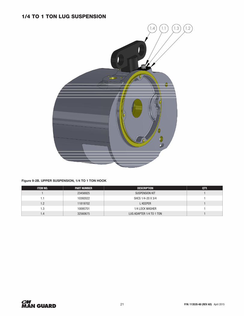
1/4 TO 1 TON LUG SUSPENSION
Figure 9-2B. UPPER SUSPENSION, 1/4 TO 1 TON HOOK
ITEM NO. PART NUMBER DESCRIPTION QTY.
1 23456925 SUSPENSION KIT 1
1.1 10392022 SHCS 1/4-20 X 3/4 1
1.2 11819702 L KEEPER 1
1.3 10095701 1/4 LOCK WASHER 1
1.4 32560675 LUG ADAPTER 1/4 TO 1 TON 1
1.4 1.1 1.3 1.2

P/N: 113535-60 (REV AD) April 201522
3
2
8
1
412
11
10
7
9
5
6
2 TON RIGID HOOK SUSPENSION
Figure 9-2C. UPPER SUSPENSION, 2 TON HOOK
ITEM NO. PART NUMBER DESCRIPTION QTY.
1 11819702 L KEEPER 1
2 10095701 LOCK WASHER 1
3 21648701 UPPER HOOK ASSEMBLY 1
4 33321701 2 TON UPPER BLOCK ASSEMBLY 1
5 10764501 BUSHING LOCK 1
6 10764801 LOCK PLATE 1
7 NO14 SHCS #10-24 1/2 2
8 10763901 PIN GROOVED STRAIGHT F 4
9 10381011 SHCS #10-24 5/16 1
10 10404510 LOCK WASHERS 3
11 10036205 COTTER PIN 1
12 10731901 PIN 3/8 DIA X 1-7/8 1
13 10392022 SHCS 1/4-20 X 3/4 (NOT SHOWN) 1
To enable us to expedite your parts order, always give Model and Catalog Number and Electric Current of Hoist. (See nameplate.)

P/N: 113535-60 (REV AD) April 201523
2 TON LUG SUSPENSION
Figure 9-2D. UPPER SUSPENSION, 2 TON LUG
ITEM NO. PART NUMBER DESCRIPTION QTY.
1 32560625K SUSPENSION KIT 1
2 33321701 UPPER BLOCK ASSEMBLY 2 TON 1
3 10036205 PIN COTTER 3/32 X 3/4 1
4 10731901 PIN 3/8 DIA X 1-7/8 1

P/N: 113535-60 (REV AD) April 201524
22502901
3 TON UPPER LIMITED ROTATION HOOK SUSPENSION
Figure 9-2E. UPPER SUSPENSION, 3 TON HOOK
ITEM NO. PART NUMBER DESCRIPTION QTY.
1 42863003 HANGER BRACKET 3 TON 1
2 21556502 SPROCKET 1
3 10614106 BUSHING DU 2
4 11273002 PIN IDLER SPROCKET 1
5 10171682 PIN ROLL SLOTTED SPRINT (NOT SHOWN) 1
6 10346106 WASHER FLAT 2
7 11272602 CONNECTING ROD 1
8 11565401 ROUND NUT 1
9 10764301 HEX BUSHING 1
10 NO8106 RETAINING RING EXTERNAL OPEN 2
11 11272801 CONNECTING PIN HANGER 1
12 22502901 LIMITED ROTATION HOOK AND NUT ASSEMBLY 1
13 10816508 BEARING THRUST WASHER DU 1
14 10099658 PIN GROOVED STRAIGHT A 1
To enable us to expedite your parts order, always give Model and Catalog Number and Electric Current of Hoist. (See nameplate.)

P/N: 113535-60 (REV AD) April 201525
UT UPPER LUG SUSPENSION
Figure 9-2F. UPPER LUG SUSPENSION
ITEM NO. PART NUMBER DESCRIPTION QTY.
1 45142602Y FRAME MACHINING W/O MOTOR RABBET (YELLOW) 1
2 42863003 HANGER BKT BEH 3 TON 1
3 21556502 SPROCKET 1
4 10614101 BUSHING DU 2
5 11273002 PIN IDLER SPROCKET 1
6 10171682 PIN ROLL SLOTTED SPRING (NOT SHOWN) 1
7 10099658 GROOVE PIN 1
8 10346106 WASHER FLAT 2
9 11272602 CONNECTING ROD 1
10 11565401 NUT-ROUND 3/4" 1
11 10764301 BUSHING 1
12 NO8106 RETAINING RING EXTERNAL OPEN 2
13 11272801 CONNECTING PIN HANGER 1
14 42863123 SUSPENSION ADAPTER 1
15 11275001 SPHERICAL WASHER 1
16 11272701 ROUND NUT 1
17 22429803 ROUND NUT 1
18 10231001 WASHER FLAT 1
A
A
4
7
1
5
3
SCALE: (1 : 5)
14
1516
9
13
11
17
10
8
12
18
SECTION A-A
2
A
A
4
7
1
5
3
SCALE: (1 : 5)
14
1516
9
13
11
17
10
8
12
18
SECTION A-A
2

P/N: 113535-60 (REV AD) April 201526
1/4 TO 1 TON LOWER BLOCK ASSEMBLY
Figure 9-3G. LOWER HOOK BLOCK ASSEMBLY 1/4 TO 1 TON
ITEM NO. 1/4 TON CODE 1/2 TON CODE 1 TON CODE DESCRIPTION QTY.
1 28683 28683 35651 LOWER BLOCK ASSEMBLY 1

P/N: 113535-60 (REV AD) April 201527
2 TON LOWER HOOK BLOCK ASSEMBLY
Figure 9-3H. LOWER HOOK BLOCK ASSEMBLY 2 TON
ITEM NO. PART NUMBER DESCRIPTION QTY.
1 21556698 2 TON LOWER BODY BLOCK 1
2 21556701 CENTER GUIDE 1
3 10694301 SCREW FILLISTER HEAD SLOTTED 1
4 21556501 SPROCKET 1
5 10346105 WASHER FLAT 1
6 10755701 BUSHING 1
7 10732101 PIN 1
8 10732201 LOCK PIN 1
9 21251901 HOOK AND NUT ASSEMBLY 1
10 10763901 PIN GROOVED SAIGHT F 1
11 21655803 SHIELD 1
12 10436012 THRUST WASHER 2
13 10409104 THRUST BEARING 1
14 NO6099 LUBRICATION FITTING 1/16" DRIVE 1
To enable us to expedite your parts order, always give Model and Catalog Number and Electric Current of Hoist. (See nameplate.)

P/N: 113535-60 (REV AD) April 201528
22459401
3 TON LOWER BLOCK ASSEMBLY
Figure 9-3I. LOWER HOOK BLOCK ASSEMBLY 3 TON
ITEM NO. PART NUMBER DESCRIPTION QTY.
1 32584410 3 TON HOOK BLOCK 1
2 10732101 PIN 1
3 10755701 BUSHING DU 1
4 21556501 HOOK BLOCK SPROCKET 1
5 10732201 LOCK PIN 1
6 10346106 WASHER FLAT 1
7 21556701 CENTER GUIDE 1
8 11272901 CONNECTING LINK 1
9 10770002 PIN DOWEL 1
10 10694301 SCREW 1
11 10816508 BEARING THRUST WASHER 1
12 22459401 HOOK AND NUT ASSEMBLY 1
13 10099658 PIN 1

P/N: 113535-60 (REV AD) April 201529
GEARCASE ASSEMBLY EXPLODED VIEW
Figure 9-4. GEARCASE ASSEMBLY

P/N: 113535-60 (REV AD) April 201530
GEARCASE ASSEMBLY
Figure 9-4. GEARCASE ASSEMBLY, CONTINUED
ITEM NO. PART NUMBER DESCRIPTION QTY.
1 45142650C DIE-CASE FRAME (CASTING 1
2 A, B & C 22952903 SPROCKET ASSEMBLY 1/4 AND 1/2 TON UNITS ONLY 1
2 A, B & C 22952901 SPROCKET ASSEMBLY 1, 2 AND 3 TON UNITS ONLY
3 A, B & C 23247801 SPROCKET BEARING AND SEAL ASSEMBLY
4 10817301 BEARING THRUST WASHER 1
5 10380509 BEARING NEEDLE CLOSED 1
6 10380513 BEARING NEEDLE CLOSED 1
7 21552350 BEARING RETAINER 1
8 31177210 GASKET 1
9 21555601 CHAIN GUIDE (1/4-1/2 TON) 1
9 21555801 CHAIN GUIDE (1-3 TON) 1
10 SEE BELOW SPROCKET GEAR 1
10 21416903 1/4 TON 16 FPM, 1/2 TON 16 FPM
10 21417003 1/4 TON 32 FPM, 1/2 TON 32 FPM
10 21988103 1 TON 16 FPM, 1 TON 32 FPM, 2 TON 8 FPM, 2 TON 16 FPM, 3 TON 5 FPM AND 3 TON 10 FPM
11 10770007 DOWEL PIN 2
12 11823201 CHAIN GUIDE PIN 2
13 10392007 #10-24 X 1/2 4
14 1410261104 RETAINING RING 2
15 10008301 RETAINING RING 3
16 11619107 PIPE PLUG HEX SOCKET 2
17 10377306 BEARING 1
18 SEE BELOW MAN GUARD LOAD PROTECTOR SINGLE SPEED UNITS ONLY (NOT SHOWN) 1
18 23456134 1/4 TON 16 FPM
19 23456135 1/4 32 FPM
20 23456132 1/2 TON 32 FPM, 1 TON 16 FPM, 1 TON 32 FPM, 2 TON 8 FPM, 2 TON 16 FPM, 3 TON 10 FPM AND 3 TON 5 FPM
20 23456131 1/2 TON 16 FPM
21 SEE BELOW LOAD-BRAKE/MAN GUARD VARIABLE SPEED UNITS 1
21 51659034 1/4 TON 16 FPM
21 51659035 1/4 43 FPM
21 51659032 1/2 TON 32 FPM, 1 TON 6 FPM, 1 TON 32 FPM, 2 TON 8 FPM, 2 TON 16 FPM, 3 TON 10 FPM AND 3 TON 5 FPM
21 51659031 1/2 TON 16 FPM
22 10417701 C-CLIP 1
23 10402823 SLEEVE BEARING 1
24 NO3042 BEARING 1
60 44468913 SHAFT INTERMEDIATE ASSEMBLY 1 TO 3 TON UNITS ONLY 1

P/N: 113535-60 (REV AD) April 201531
SINGLE SPEED GEARCASE COVER WITH CONTROLS 1 PHASE UNITS
Figure 9-5A. CONTROLS SINGLE SPEED SINGLE PHASE
ITEM NO. PART NUMBER DESCRIPTION QTY.
1 44485160C GEARCASE COVER WITH BEARING 1
2 11741009 TERMINAL STRIP 1
3 10755401 SPACER 2
4 10381401 PHILLIP SCREW PAN HEAD #10-24X1 2
5 A/B 22827201 TRANSFORMER 115/230 - 115V SEC. 1
6 10017807 10-24 1/4 PAN HEAD SELF TAPPING 2
7 11832399 FUSE HOLDER FOR GLR FUSES 1
8 11832302 GLR FUSE 1
9 22845703 REVERSING CONTACTOR ASSEMBLY 110V 1
10 11050704 10-24 3/8 PAN HEAD SELF TAPPING 2
11 10734601 GROMMET 2
12 20055696 WIRE GROUND #16 GA X 7" LONG COLOR GREEN 1
13 10486615 WIRE JUMPER #14 GA X 3" COLOR BLACK 1
14 22700310 WIRE JUMPER #16 GA X 7.5" COLOR BLACK 5
15 20995407 WIRE JUMPER #16 GA X 2.5" COLOR RED 1
NOTE:
1. Jumper and wire connections not show.
2. See wiring diagrams for wire connections.
To enable us to expedite your parts order, always give Model and Catalog Number and Electric Current of Hoist. (See nameplate.)

P/N: 113535-60 (REV AD) April 201532
SINGLE SPEED GEARCASE COVER WITH CONTROLS 3 PHASE UNITS
Figure 9-5B. CONTROLS SINGLE SPEED THREE PHASE
ITEM NO. PART NUMBER DESCRIPTION QTY.
1 44485160C GEARCASE COVER WITH BEARING 1
2 11741009 TERMINAL STRIP 1
3 10755401 SPACER 2
4 10381401 PHILLIP SCREW PAN HEAD #10-24X1 2
5 20991909 TRANSFORMER 115/230 - 115V SEC. 1
6 10017807 10-24 1/4 PAN HEAD SELF TAPPING 2
7 11832399 FUSE HOLDER FOR GLR FUSES 1
8 11832302 GLR FUSE 1
9 22845703 REVERSING CONTACTOR ASSEMBLY 110V 1
10 11050704 10-24 3/8 PAN HEAD SELF TAPPING 2
11 10734601 GROMMET 2
12 20055696 WIRE GROUND #16 GA X 7" LONG COLOR GREEN 1
13 10486615 WIRE JUMPER #14 GA X 3" COLOR BLACK 2
14 22700310 WIRE JUMPER #16 GA X 7.5" COLOR BLACK 6
NOTE:
1. Jumper and wire connections not show.
2. See wiring diagrams for wire connections.
6
10

P/N: 113535-60 (REV AD) April 201533
TWO SPEED GEARCASE COVER WITH CONTROLS 575 VOLT 3 PHASE UNITS
Figure 9-5C. CONTROLS TWO 575 VOLT ONLY
ITEM NO. PART NUMBER DESCRIPTION QTY.
1 44485161C/ 44485160C
GEARCASE COVER BEARING ASSEMBLY WITHOUT EXTERNAL COUNTER WEIGHT/ WITH EXTERNAL COUNTER WEIGHT
1
2 10017807 10-24 1/4 PAN HEAD SELF TAPPING 3
3 NO7093 PHILLIP SCREW PAN HEAD #10-24 X 3/8 SCREW PHILLIPS PAN HEAD SEMS 2
4 22845703 CONTACTOR AND MOUNTING PLATE ASSEMBLY 1
5 20991910 TRANSFORMER 575V 115 V 20VA 1
6 20055696 WIRE JUMPER #16 GAUGE X 7" LONG COLOR GREEN 1
7 23515203 FUSE HOLDER ASSEMBLY 1/2 AMP 250V 1
8 10486615 WIRE JUMPER #14 GAUGE X 3" LONG COLOR BLACK 4
9 22700310 WIRE JUMPER #16 GAUGE X 7 1/2" LONG COLOR BLACK 3
10 11050712 8-32 X 1/2 PAN HEAD PHILLIPS SEM 2
11 22845731 2 SPEED CONTACTOR AND MOUNTING PLATE ASSEMBLY 1
12 22700311 WIRE JUMPER #16 GA X 5" LONG 1
44485113C /44485114C
9 9
9
12
8
11
10

P/N: 113535-60 (REV AD) April 201534
VFD GEARCASE COVER WITH CONTROLS 230 VOLT AND 460 VOLT MODELS
Figure 9-5D. CONTROLS VARIABLE SPEED THREE PHASE
ITEM NO. PART NUMBER DESCRIPTION QTY.1 44485160Y GEARCASE COVER BEARING ASSEMBLY 1
2 11741009 TERMINAL STRIP 1
3 20991909 TRANSFORMER 230/460V 115V 20VA 1
4 23515203 FUSE HOLDER ASSEMBLY 1
5 10734601 GROMMET 2
6 45226901 MOUNTING BRACKET VFC 1
7 11050706 8-32 X 1 PHILLIPS PAN HEAD SEM 2
8 29009 DIN-RAIL 4.50" LONG 1
9 33310931 CONTACTOR, MINI NON-REVERSING 1
10 11050712 8-32 X 1/2 PAN HEAD PHILLIPS SEM 4
11 11050704 SCREW PAN HEAD PHILLIPS 4
12 NO8102 1/4-20 X 1/2 PHILLIP HEAD SEMS (NOT SHOWN) 1
13 10017807 10-24 1/4 PAN HEAD SELF TAPPING (NOT SHOWN) 1
14 33311996 SUPPRESSOR MODULE WITH LED 1
15 22700310 WIRE #16 GAUGE BLACK 4
16 10486614 WIRE JUMPER #14 MTW 10" L BLACK SOLDER DIP 3
17 10486619 WIRE JUMPER #18 GA X 13 1/2" LONG COLOR RED 8
18 20055698 WIRE ASSEMBLY GROUNDED WITH RING 1
19 11782702 CONNECTOR PUSHWIRE YELLOW 1/4
20 11782704 CONNECTOR PUSHWIRE ORANGE 1/0
21 33179001 ELECTRICAL COVER EXTENSION 1
22 VFD NUMBER VFD DESCRIPTION
A 45199721 230 VOLTS, 1/4 TON 16 AND 32 FPM AND 1/2 TON 16 FPM ^
B 45199722 230 VOLTS, 1/2 TON 32 FPM AND 1 TON 16 FPM ^
C 45199724 230 VOLTS, 1 TON 16 32 FPM 2 TON 16 FPM AND 3 TON 10 FPM ^
D 45199741 460 VOLTS, 1/4 TON 16 AND 32 FPM AND 1/2 TON 16 FPM ^
E 45199742 460 VOLTS, 1/2 TON 32 FPM AND 1 TON 16 FPM ^
F 451743 460 VOLTS, 1 TON 16 32 FPM 2 TON 16 FPM AND 3 TON 10 FPM ^
29 NO7093 SCREW PAN HEAD PHILLIPS SEMS (NOT SHOWN) 3
NOTE:
1. Item 23 A-F see description for proper selection of VFD. Quantity. Of 1 required.

P/N: 113535-60 (REV AD) April 201535
AC BRAKE
Figure 9-6. BRAKES
ITEM NO. PART NUMBER VOLTAGE
HOIST MODEL
MG2518 MG2532 MG5016 MG5032 MG0116 MG0132 MG0216 MG0310 MG0208 MG0305
A
45097301 230/460-1-60 X
45097303 575-1-60 X
45097304 115/208-230-1-60 X
45097307 230/460-1-60 X X
45097309 575-1-60 X X
45097310 115/208-230-1-60 X X
45097313 230/460-1-60 X X X X X
45097315 575-1-60 X X X X X
45097316 115/208-230-1-60 X X X X
B 45097396 SOLENOID KIT
C 450997399 BRAKE HUB
D 450997350 BRAKE DISC (SPECIFY QTY. SOME BRAKE ASSEMBLIES USE 2)
E 45097397B BRAKE COVER (NOT SHOWN)
F 45097395HARDWARE KIT FOR BRAKE COVER AND HUB (NOT SHOWN)
CONSISTING OF 2 NUTS & LOCKWASHERS FOR COVER, 2 SET SCREWS FOR BRAKE HUB, AND 1 WOODRUFF KEY
G 10095703 3/8 LOCKWASHER FOR BRAKE MOUNTING (NOT SHOWN)
H 10119413 RETAINING RING FOR BRAKE HUB (NOT SHOWN)
I NO2112 SHCS 3/8 FOR BRAKE MOUNTING (NOT SHOWN)

P/N: 113535-60 (REV AD) April 201536
MOTORS
Figure 9-7. MOTORS
PART NUMBER VOLTAGE
HOIST MODEL
MG2518 MG2532 MG5016 MG5032 MG0116 MG0132 MG0216 MG0310 MG0208 MG0305
45089072B 115/230V 56 .25 HP 1800 RPM X
45089074B 115/230V 56 .5 HP 1800 RPM X X
45089076B 115/230V 56 1 HP 1800 RPM X X X X
45089102B 230/460C 190/380V 56 .25 HP 1800 RPM X
45089103B 575V 56 .25 HP 1800 RPM X
45089105B 230/460V 190/380V 56 .5 HP 1800 RPM X X
45089106B 575 V 56 .5 HP 1800 RPM X X
45089108B 230/460V 190/380V 56 1 HP 1800 RPM X X
45089109B 575 56 1 HP 1800 RPM X X
45089122B 230/460V 190/380 56 2/5 HP 3600 RPM X X X
45089123B 575V 56 2.5 HP 3600 RPM X X X
45089204B 2 SPEED 575V 56 2.5-7.5 HP 3600/1200 RPM X X X
45089212B 2 SPEED 575V 56 .5-.17 HP 1800/600 RPM X X X
45089216B 2 SPEED 575V 56 1-.33 HP 3600/1200 RPM X X

P/N: 113535-60 (REV AD) April 201537
CHAIN WITH LIMIT SWITCH
Figure 9-8. LIMIT SWITCH ASSEMBLY WITH STOPS AND CHAIN
ITEM NO. PART NUMBER DESCRIPTION QTY.
1 11829201 HEX FLANGE HEAD BOLT 1
2 22716301 LIMIT SWITCH ASSEMBLY 1
3 33215901 LIMIT LEVER 1
4 24016K CHAIN STOP ASSEMBLY 1
5 10450808 LIMIT SWITCH KEY (NOT SHOWN) 1
6A 11820501C END COVER (STANDARD & VFD) 1
6B 10878506C END COVER (INTERNAL C'WEIGHT) 1
6C 33179020C EXTENSION FRAME 9VFD ONLY) 1
7A 10777101 END COVER SCREWS (STANDARD & INTERNAL C'WEIGHT) 3
7B 10777102 END COVER SCREWS (VFD ONLY) 3
7C 22725901/01 EXTERNAL C'WEIGHT COVER SCREWS (ONLY) 2/1
8 10095701 END COVER LOCK WASHERS 3
9 10409702 C-CLIP SCREW RETAINERS FOR ITEMS 8A, B OR C 3
10 10327306 NUT EXTERNAL C'WEIGHT (NOT SHOWN) 3
11 21910601 INTERNAL C'WEIGHT (NOT SHOWN) 1
12 10439102 INTERNAL C'WEIGHT SCREWS (NOT SHOWN) 2
13 43945901C EXTERNAL C'WEIGHT (NOT SHOWN) 1
14 10422705 VENT PLUG 1/4-18NPT (NOT SHOWN) 1
* Chain Quantity = ((DROP) + (1.75')) for 1/4 to 1 ton hoist. (((DROP) X (2)) + 3.25') for 2 ton Hoist and (((DROP) X (3)) + 4.75') for 3 ton hoist.
4
1042270515 1VENT PLUG 1/4-18NPT (NOT SHOWN)
CCC
C
6A 6B 6C
7A
8
9
10
7B 7C

P/N: 113535-60 (REV AD) April 201538
Figure 9-9a. WIRING DIAGRAMS

P/N: 113535-60 (REV AD) April 201539
Figure 9-9b. WIRING DIAGRAMS

P/N: 113535-60 (REV AD) April 201540
Figure 9-9c. WIRING DIAGRAMS

P/N: 113535-60 (REV AD) April 201541
Figure 9-9d. WIRING DIAGRAMS
Third Angle Projection
Dimensional Units INCH
Standard:
Material No:
Material:
6 5
B
D
E
F
Modeled:
Drawn:Approved:
Original Scale:
Original project:Design Authority:
0" to 60".x ± .020.xx ± .010.xxx ± .005
Over 60''± .025± .015± .010
Ang ± 0° 30' ± 0° 30'
Format Number:
ByDateDescription of changeRev.ECN
Description:
CSheet
Standard DimensionalTolerances Unless
Otherwise Specified
4 3 2 1
A
Columbus McKinnon CorporationHoist & Rigging - Americas
Amherst, NY USA
NO
TICE
TO P
ERSO
NS
REC
EIV
ING
THI
S D
RAW
ING
AN
D/O
R TE
CHN
ICA
L IN
FORM
ATIO
NC
olum
bus M
cKin
non
Cor
pora
tion
(CM
CO
) cla
ims p
ropr
ieta
ry ri
ghts
in th
e m
ater
ial d
isclo
sed
her
eon.
Thi
s dra
win
g an
d/o
r tec
hnic
al in
form
atio
n is
issue
d in
conf
iden
ce fo
r eng
inee
ring
info
rmat
ion
only
and
may
not
be
repr
oduc
ed o
r use
d to
man
ufac
ture
any
thin
g sh
own
or re
ferre
d to
her
eon
with
out d
irect
perm
issio
n fro
m C
MC
O to
the
user
. Thi
s dra
win
g an
d/o
r tec
hnic
al in
form
atio
n is
loan
ed fo
r mut
ual a
ssist
ance
and
is su
bjec
t to
reca
ll by
CM
CO
at a
ny ti
me.
This
dra
win
g an
d/o
r tec
hnic
al in
form
atio
n is
the
prop
erty
of C
MC
O.
Columbus McKinnon CorporationAmherst, NY USA
123456
G
H
B
D
E
F
A
G
H
1133325102
WIRING DIAGRAM BUDGIT 230V1-SPD 1-PHASE RECONN. W/ PLS-
--
-
SDP
-
-
Library
-
-
15305 AB UPDATED TITLE BLOCK 12/2/2011 PGH
- - - -
- - - -
DN
UP

P/N: 113535-60 (REV AD) April 201542
Figure 9-9e. WIRING DIAGRAMS
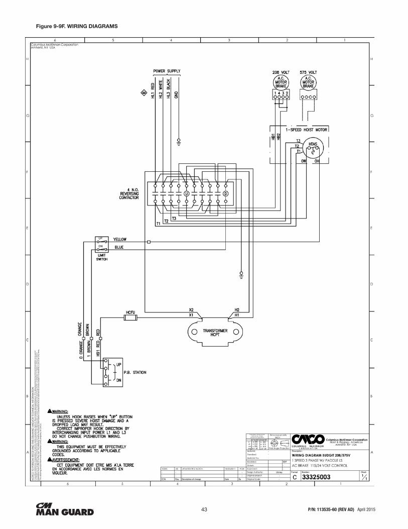
P/N: 113535-60 (REV AD) April 201543
Figure 9-9F. WIRING DIAGRAMS

P/N: 113535-60 (REV AD) April 201544
Figure 9-9G. WIRING DIAGRAMS
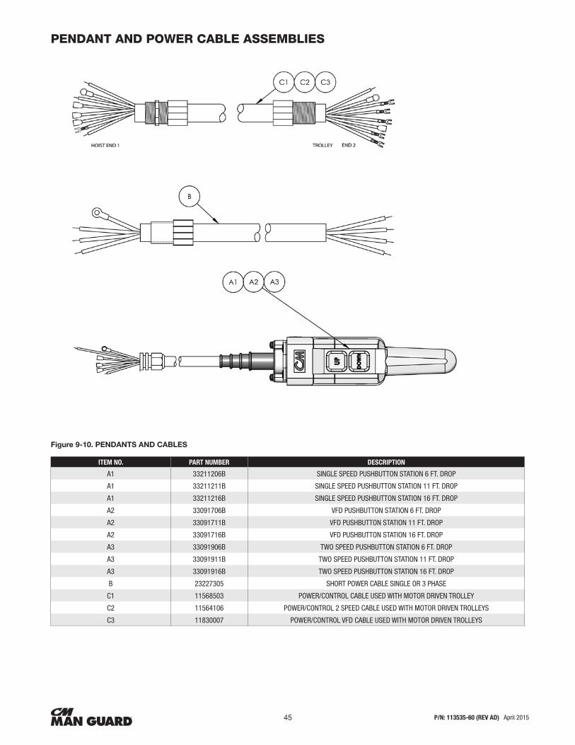
P/N: 113535-60 (REV AD) April 201545
PENDANT AND POWER CABLE ASSEMBLIES
Figure 9-10. PENDANTS AND CABLES
ITEM NO. PART NUMBER DESCRIPTION
A1 33211206B SINGLE SPEED PUSHBUTTON STATION 6 FT. DROP
A1 33211211B SINGLE SPEED PUSHBUTTON STATION 11 FT. DROP
A1 33211216B SINGLE SPEED PUSHBUTTON STATION 16 FT. DROP
A2 33091706B VFD PUSHBUTTON STATION 6 FT. DROP
A2 33091711B VFD PUSHBUTTON STATION 11 FT. DROP
A2 33091716B VFD PUSHBUTTON STATION 16 FT. DROP
A3 33091906B TWO SPEED PUSHBUTTON STATION 6 FT. DROP
A3 33091911B TWO SPEED PUSHBUTTON STATION 11 FT. DROP
A3 33091916B TWO SPEED PUSHBUTTON STATION 16 FT. DROP
B 23227305 SHORT POWER CABLE SINGLE OR 3 PHASE
C1 11568503 POWER/CONTROL CABLE USED WITH MOTOR DRIVEN TROLLEY
C2 11564106 POWER/CONTROL 2 SPEED CABLE USED WITH MOTOR DRIVEN TROLLEYS
C3 11830007 POWER/CONTROL VFD CABLE USED WITH MOTOR DRIVEN TROLLEYS

P/N: 113535-60 (REV AD) April 201546
HDPE CHAIN CONTAINERS
Figure 9-11. CHAIN CONTAINERS
CODE # 922440 922441 922442 922443805437 MESH BAG FOR 3T 20' LIFT UNITS ONLY
MAX CHAIN 18' 28' 40' 50' 60'
"L" 8.9" 11" 14.5" 18.75" 23"

P/N: 113535-60 (REV AD) April 201547
NOTES

RECOMMENDED SPARE PARTS FOR YOUR CM HOISTSCertain parts of your hoist will, in time, require replacement under normal wear conditions.
It is suggested that the following parts be purchased for your hoist as spares for future use.
Set of Gaskets
Set of Bearings
Lower Block Assembly
Load Chain
Set of Brake Discs for Load Brake
Set of Brake Discs for Motor Brake
Push Button Station & Cable Assembly
Transformer
Contactor
Transformer Fuse
Set of Oil Seals
Limit Lever
Limit Switch Assembly
Note: When ordering parts always furnish Model and Catalog Number of Hoist and lift of hoist on which the parts are to be used.
Parts for your hoist are available from your local authorized CM Hoists repair station.
For the location of your nearest repair station, call or visit:
PHONE: (800) 888-0985 • WWW.CMWORKS.COM • FAX: (716) 689-5644
WARRANTYWARRANTY AND LIMITATION OF REMEDY AND LIABILITY
A. Seller warrants that its products and parts, when shipped, and its work (including installation, construction and start-up), when performed, will meet applicable specifications, will be of good quality and will be free from defects in material and workmanship. All claims for defective products or parts under this warranty must be made in writing immediately upon discovery and in any event, within one (1) year from shipment of the applicable item unless Seller specifically assumes installation, construction or start-up responsibility. All claims for defective products or parts when Seller specifically assumes installation, construction or start-up responsibility and all claims for defective work must be made in writing immediately upon discovery and in any event, within one (1) year from completion of the applicable work by Seller, provided; however, all claims for defective products and parts must be made in writing no later than eighteen (18) months after shipment. Defective items must be held for Seller’s inspection and returned to the original f.o.b. point upon request. THE ‘FOREGOING IS EXPRESSLY IN LIEU OF ALL OTHER WARRANTIES WHATSOEVER, EXPRESS, IMPLIED AND STATUTORY, INCLUDING, WITHOUT LIMITATION, THE IMPLIED WARRANTIES OF MERCHANTABILITY AND FITNESS.
B. Upon Buyer’s submission of a claim as provided above and its substantiation, Seller shall at its option either (i) repair or replace its product, part or work at either the original f.o.b. point of delivery or at Seller’s authorized service station nearest Buyer or (ii) refund an equitable portion of the purchase price.
C. This warranty is contingent upon Buyer’s proper maintenance and care of Seller’s products, and does not extend to normal wear and tear. Seller reserves the right to void warranty in event of Buyer’s use of inappropriate materials in the course of repair or maintenance, or if Seller’s products have been dismantled prior to submission to Seller for warranty inspection.
D. The foregoing is Seller’s only obligation and Buyer’s exclusive remedy for breach of warranty and is Buyer’s exclusive remedy hereunder by way of breach of contract, tort, strict liability or otherwise. In no event shall Buyer be entitled to or Seller liable for incidental or consequential damages. Any action for breach of this warranty must be commenced within one (1) year after the cause of action has accrued.
© 2015 Columbus McKinnon Corporation. All Rights Reserved.
USA: Ph: (800) 888.0985 • (716) 689.5400 • Fax: (716) 689.5644CANADA: Ph: (877) 264.6478 • Fax: (877) 264.6477
P/N: 113535-60 (REV AD) April 2015
Recommended