Embed Size (px)
Citation preview
Hitachi Hoists
http://www.hitachi-ies.co.jp/english/products/hst/
Hitachi Hoist Series Contents
Introduction 2
Features
List of Hoist Types
Prior to Selecting the Hoist
4
8
9
Outline
Standard Headroom Type Hoist
Low Headroom Type Hoist
Double-Rail Type Hoist
Stationary Type Hoist
Hoist with Creep Speed for Hoisting
14
20
22
25
28
V-series
30
34
36
38
39
42
43
44
45
46
49
Ultra High Lift Type Hoist
Pair Hoist
Special Hoisting Speed Type Hoist,
Special Traverse Speed Type Hoist
Special Specifications Hoist
Crane Saddles
Crane Saddle with Creep Speed
Wheel Unit for Toprun Type Saddle
Wheel Unit for Gantry Crane Saddle
Electrical Parts for Crane Saddle
For Installing the Hitachi Hoist
Standards and Applied Class to the Hitachi Hoists
Others
Standard Headroom Type Hoist
Low Headroom Type Hoist
10
12
A-series
Hitachi Hoist
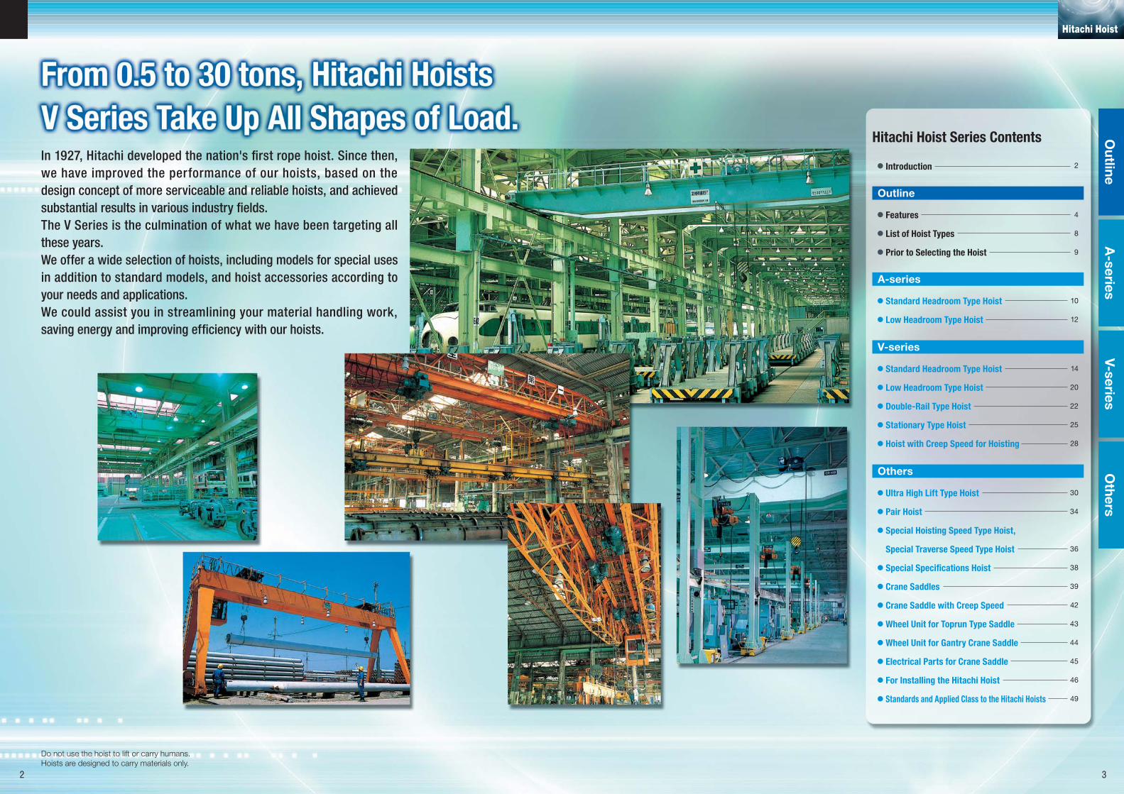
In 1927, Hitachi developed the nation's first rope hoist. Since then,
we have improved the performance of our hoists, based on the
design concept of more serviceable and reliable hoists, and achieved
substantial results in various industry fields.
The V Series is the culmination of what we have been targeting all
these years.
We offer a wide selection of hoists, including models for special uses
in addition to standard models, and hoist accessories according to
your needs and applications.
We could assist you in streamlining your material handling work,
saving energy and improving efficiency with our hoists.
Do not use the hoist to lift or carry humans.Hoists are designed to carry materials only.
A-series
Outline
V-seriesO
thers
2 3
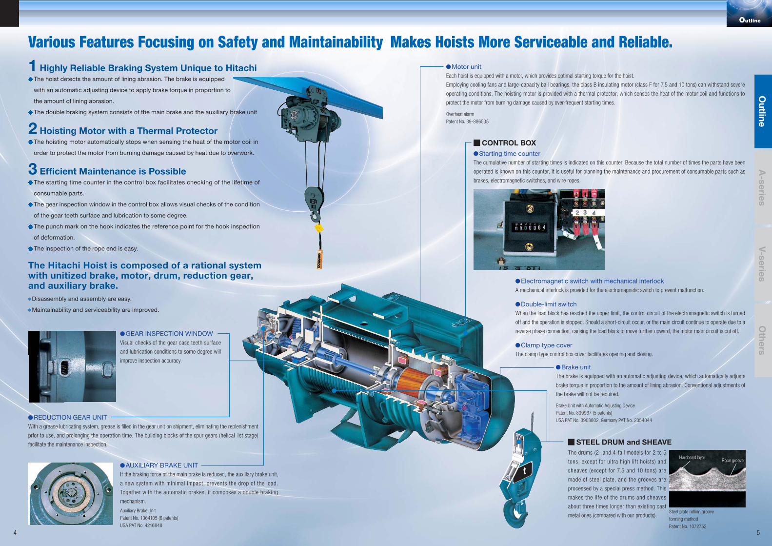
The drums (2- and 4-fall models for 2 to 5
tons, except for ultra high lif t hoists) and
sheaves (except for 7.5 and 10 tons) are
made of steel plate, and the grooves are
processed by a special press method. This
makes the life of the drums and sheaves
about three times longer than existing cast
metal ones (compared with our products).
GEAR INSPECTION WINDOWVisual checks of the gear case teeth surface
and lubrication conditions to some degree will
improve inspection accuracy.
AUXILIARY BRAKE UNITIf the braking force of the main brake is reduced, the auxiliary brake unit,
a new system with minimal impact, prevents the drop of the load.
Together with the automatic brakes, it composes a double braking
mechanism.
REDUCTION GEAR UNITWith a grease lubricating system, grease is filled in the gear unit on shipment, eliminating the replenishment
prior to use, and prolonging the operation time. The building blocks of the spur gears (helical 1st stage)
facilitate the maintenance inspection.
Motor unitEach hoist is equipped with a motor, which provides optimal starting torque for the hoist.
Employing cooling fans and large-capacity ball bearings, the class B insulating motor (class F for 7.5 and 10 tons) can withstand severe
operating conditions. The hoisting motor is provided with a thermal protector, which senses the heat of the motor coil and functions to
protect the motor from burning damage caused by over-frequent starting times.
STEEL DRUM and SHEAVE
Auxiliary Brake Unit
Patent No. 1364105 (6 patents)
USA PAT No. 4216848
Steel plate rolling groove
forming method
Patent No. 1072752
Overheat alarm
Patent No. 39-886535
Brake Unit with Automatic Adjusting Device
Patent No. 899967 (5 patents)
USA PAT No. 3908802, Germany PAT No. 2354044
CONTROL BOXStarting time counter
The cumulative number of starting times is indicated on this counter. Because the total number of times the parts have been
operated is known on this counter, it is useful for planning the maintenance and procurement of consumable parts such as
brakes, electromagnetic switches, and wire ropes.
Brake unitThe brake is equipped with an automatic adjusting device, which automatically adjusts
brake torque in proportion to the amount of lining abrasion. Conventional adjustments of
the brake will not be required.
Electromagnetic switch with mechanical interlockA mechanical interlock is provided for the electromagnetic switch to prevent malfunction.
Double-limit switchWhen the load block has reached the upper limit, the control circuit of the electromagnetic switch is turned
off and the operation is stopped. Should a short-circuit occur, or the main circuit continue to operate due to a
reverse phase connection, causing the load block to move further upward, the motor main circuit is cut off.
Clamp type coverThe clamp type control box cover facilitates opening and closing.
Hardened layer Rope groove
Outline
Various Features Focusing on Safety and Maintainability Makes Hoists More Serviceable and Reliable.1 Highly Reliable Braking System Unique to Hitachi
The hoist detects the amount of lining abrasion. The brake is equipped
with an automatic adjusting device to apply brake torque in proportion to
the amount of lining abrasion.
The double braking system consists of the main brake and the auxiliary brake unit
2 Hoisting Motor with a Thermal ProtectorThe hoisting motor automatically stops when sensing the heat of the motor coil in
order to protect the motor from burning damage caused by heat due to overwork.
3 Efficient Maintenance is PossibleThe starting time counter in the control box facilitates checking of the lifetime of
consumable parts.
The gear inspection window in the control box allows visual checks of the condition
of the gear teeth surface and lubrication to some degree.
The punch mark on the hook indicates the reference point for the hook inspection
of deformation.
The inspection of the rope end is easy.
The Hitachi Hoist is composed of a rational systemwith unitized brake, motor, drum, reduction gear,and auxiliary brake.
Disassembly and assembly are easy.
Maintainability and serviceability are improved.
A-series
Outline
V-seriesO
thers
4 5
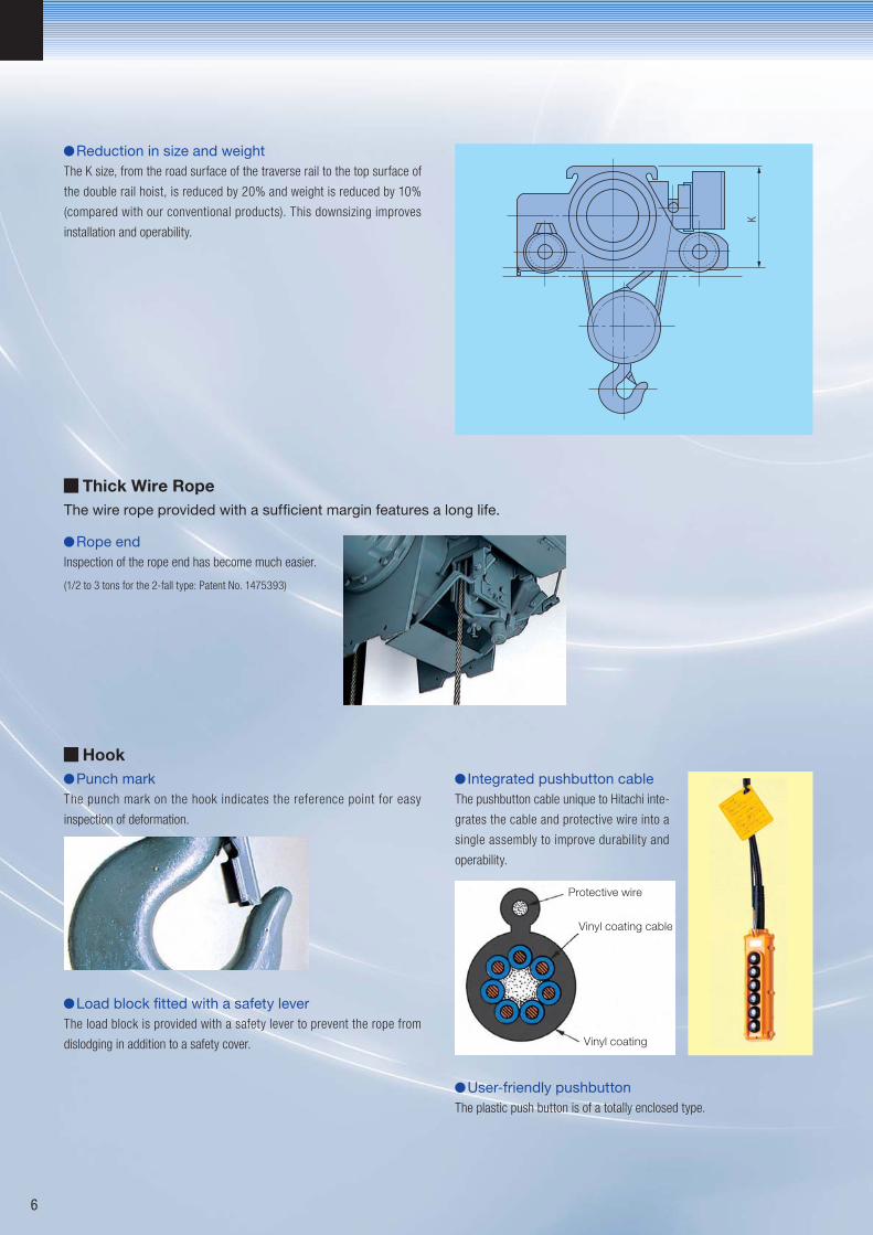
Protective wire
Vinyl coating cable
Vinyl coating
Reduction in size and weightThe K size, from the road surface of the traverse rail to the top surface of
the double rail hoist, is reduced by 20% and weight is reduced by 10%
(compared with our conventional products). This downsizing improves
installation and operability.
Thick Wire Rope
Rope endInspection of the rope end has become much easier.
The wire rope provided with a sufficient margin features a long life.
(1/2 to 3 tons for the 2-fall type: Patent No. 1475393)
HookPunch mark
The punch mark on the hook indicates the reference point for easy
inspection of deformation.
Load block fitted with a safety leverThe load block is provided with a safety lever to prevent the rope from
dislodging in addition to a safety cover.
Integrated pushbutton cableThe pushbutton cable unique to Hitachi inte-
grates the cable and protective wire into a
single assembly to improve durability and
operability.
User-friendly pushbuttonThe plastic push button is of a totally enclosed type.
K
6
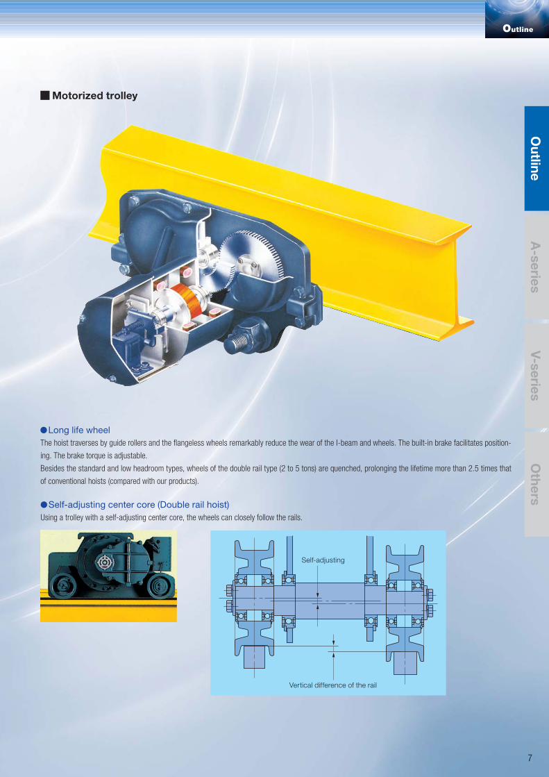
Motorized trolley
Long life wheelThe hoist traverses by guide rollers and the flangeless wheels remarkably reduce the wear of the I-beam and wheels. The built-in brake facilitates position-
ing. The brake torque is adjustable.
Besides the standard and low headroom types, wheels of the double rail type (2 to 5 tons) are quenched, prolonging the lifetime more than 2.5 times that
of conventional hoists (compared with our products).
Self-adjusting center core (Double rail hoist)Using a trolley with a self-adjusting center core, the wheels can closely follow the rails.
Self-adjusting
Vertical difference of the rail
Outline
A-series
Outline
V-seriesO
thers
7
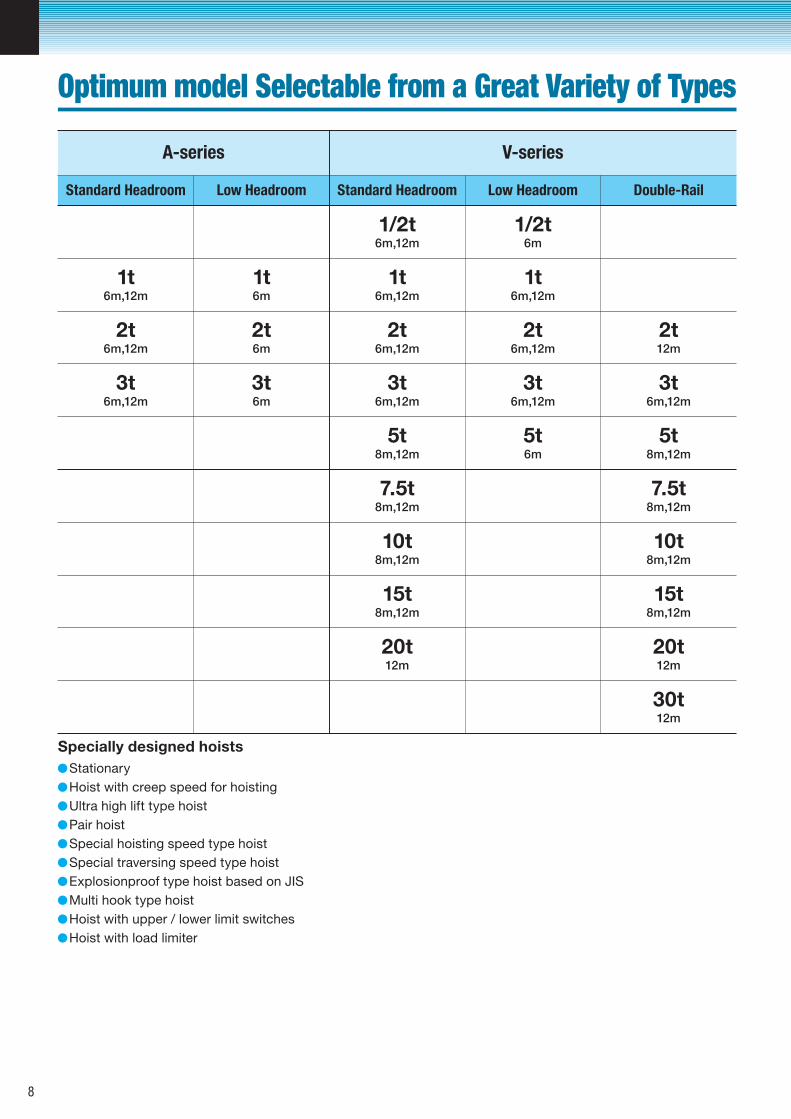
Specially designed hoists
1t6m,12m
1t6m
1t6m,12m
1t6m,12m
2t6m,12m
2t6m
2t6m,12m
2t6m,12m
2t12m
3t6m,12m
3t6m
3t6m,12m
3t6m,12m
3t6m,12m
5t8m,12m
5t6m
5t8m,12m
7.5t8m,12m
7.5t8m,12m
10t8m,12m
10t8m,12m
15t8m,12m
15t8m,12m
20t12m
20t12m
30t12m
1/2t6m,12m
1/2t6m
Standard Headroom Low Headroom Double-RailLow HeadroomStandard Headroom
A-series V-series
Hoist with upper / lower limit switchesHoist with load limiter
Hoist with creep speed for hoistingStationary
Ultra high lift type hoistPair hoistSpecial hoisting speed type hoistSpecial traversing speed type hoistExplosionproof type hoist based on JISMulti hook type hoist
Optimum model Selectable from a Great Variety of Types
8
Rated load
indicated
by tons
No
mark
H V-series
Standard headroom
type・・・・・・・・・・M
Low headroom
type・・・・・・・・・・L
Double rail type・・・D
A-series
Standard headroom
type・・・・・・・・・AM
Low headroom
type・・・・・・・・・AL
Manual driven
trolley・・・・・・・・P
Chain driven
trolley・・・・・・・・C
Motorized
trolley・・・・・・・・T
Low lift High liftCapacity
Hoisting liftHoist type Trolley type
Serial numbers are applied to improved No.
Without Motorized Trolley 2
Type No. of push buttons Indication
No cable is provided in the cable power feed system.
Standard push-buttons
With Motorized Trolley
Except 5t Double Rail Type (up to 5t)6
With Motorized Trolley
Incude 5t Double Rail Type (7.5t and up)8 ON OFF
Suspension-type with chain-driven trolley Cable
Cable
Type Power feed system
Power feed system
With motorized trolley
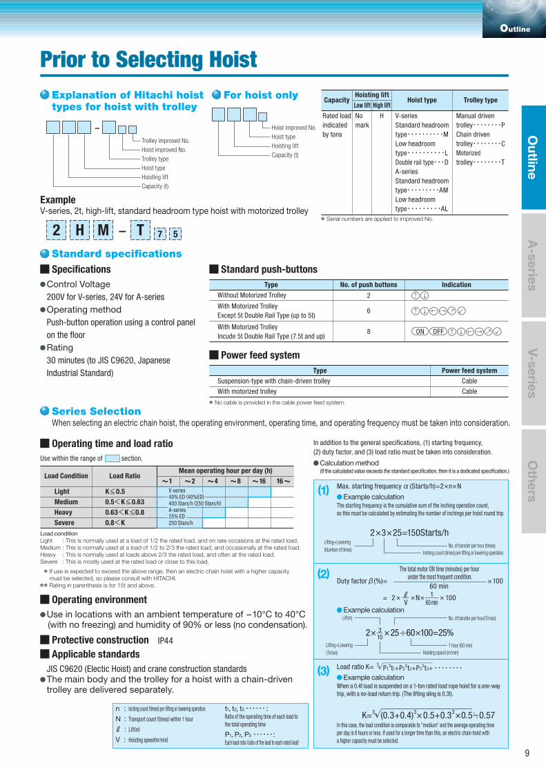
Operating time and load ratio
When selecting an electric chain hoist, the operating environment, operating time, and operating frequency must be taken into consideration.
If use is expected to exceed the above range, then an electric chain hoist with a higher capacity must be selected, so please consult with HITACHI.Rating in parenthesis is for 15t and above.
Load Condition
Light
Medium
Heavy
Severe
Load Ratio
K 0.5
0.5 K 0.63
0.63 K 0.8
0.8 K
Use within the range of section.
In addition to the general specifications, (1) starting frequency,
(2) duty factor, and (3) load ratio must be taken into consideration.
Operating environment
Use in locations with an ambient temperature of -10°C to 40°C (with no freezing) and humidity of 90% or less (no condensation).
Mean operating hour per day (h)
Load conditionLight : This is normally used at a load of 1/2 the rated load, and on rare occasions at the rated load.Medium : This is normally used at a load of 1/2 to 2/3 the rated load, and occasionally at the rated load.Heavy : This is normally used at loads above 2/3 the rated load, and often at the rated load.Severe : This is mostly used at the rated load or close to this load.
Series Selection
Calculation method(If the calculated value exceeds the standard specification, then it is a dedicated specification.)
Applicable standards
JIS C9620 (Electic Hoist) and crane construction standardsThe main body and the trolley for a hoist with a chain-driventrolley are delivered separately.
Protective construction IP44
(1) Max. starting frequency
The starting frequency is the cumulative sum of the inching operation count,
so this must be calculated by estimating the number of inchings per hoist round trip.
(Starts/h)=2 n N
Example calculation
No. of transfer per hour (times)Lifting+Lowering
(Number of times)Inching count (times) per lifting or lowering operation.
2 3 25=150Starts/h
(2)Duty factor (%)=
= 2 N 100
100
The total motor ON time (minutes) per hour under the most frequent condition.
60 min
Example calculation
1 hour (60 min)Lifting+Lowering
(Times)
No. of transfer per hour(Times)Lift(m)
Hoisting speed (m/min)
2 25 60 100=25%103
(3) Load ratio K=
When a 0.4t load is suspended on a 1-ton rated load rope hoist for a one-way
trip, with a no-load return trip. (The lifting sling is 0.3t).
In this case, the load condition is comparable to "medium" and the average operating time
per day is 8 hours or less. If used for a longer time than this, an electric chain hoist with
a higher capacity must be selected.
P13t1+P2
3t2+P33t3+
3
Example calculation
(0.3+0.4)3 0.5+0.3
3 0.5 0.57K=
V 60 min1
3n : Inching count (times) per lifting or lowering operation.
N : Transport count (times) within 1 hour
t1, t2, t3 :
P1, P2, P3 :
Ratio of the operating time of each load to
the total operating time
Each load ratio (ratio of the load to each rated load)
Lift(m)
V :
:
Hoisting speed(m/min)
Trolley type
Hoist type
Hoisting lift
Capacity (t)
Hoist improved No.
Trolley improved No.
V-series, 2t, high-lift, standard headroom type hoist with motorized trolleyExample
-Hoist type
Hoisting lift
Capacity (t)
Hoist improved No.
- 572 H M T
Control Voltage200V for V-series, 24V for A-series
Operating methodPush-button operation using a control panel
on the floor
Rating30 minutes (to JIS C9620, Japanese
Industrial Standard)
Specifications
Standard specifications
Explanation of Hitachi hoist types for hoist with trolley
For hoist only
1 2 4 8 16 16
V-series40% ED (40%ED)
400 Stars/h (250 Stars/h)
A-series25% ED250 Stars/h
Outline
Prior to Selecting Hoist
A-series
Outline
V-seriesO
thers
9
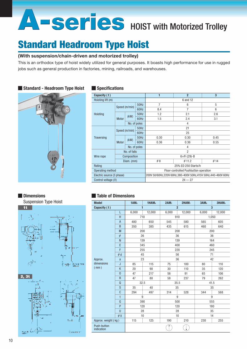
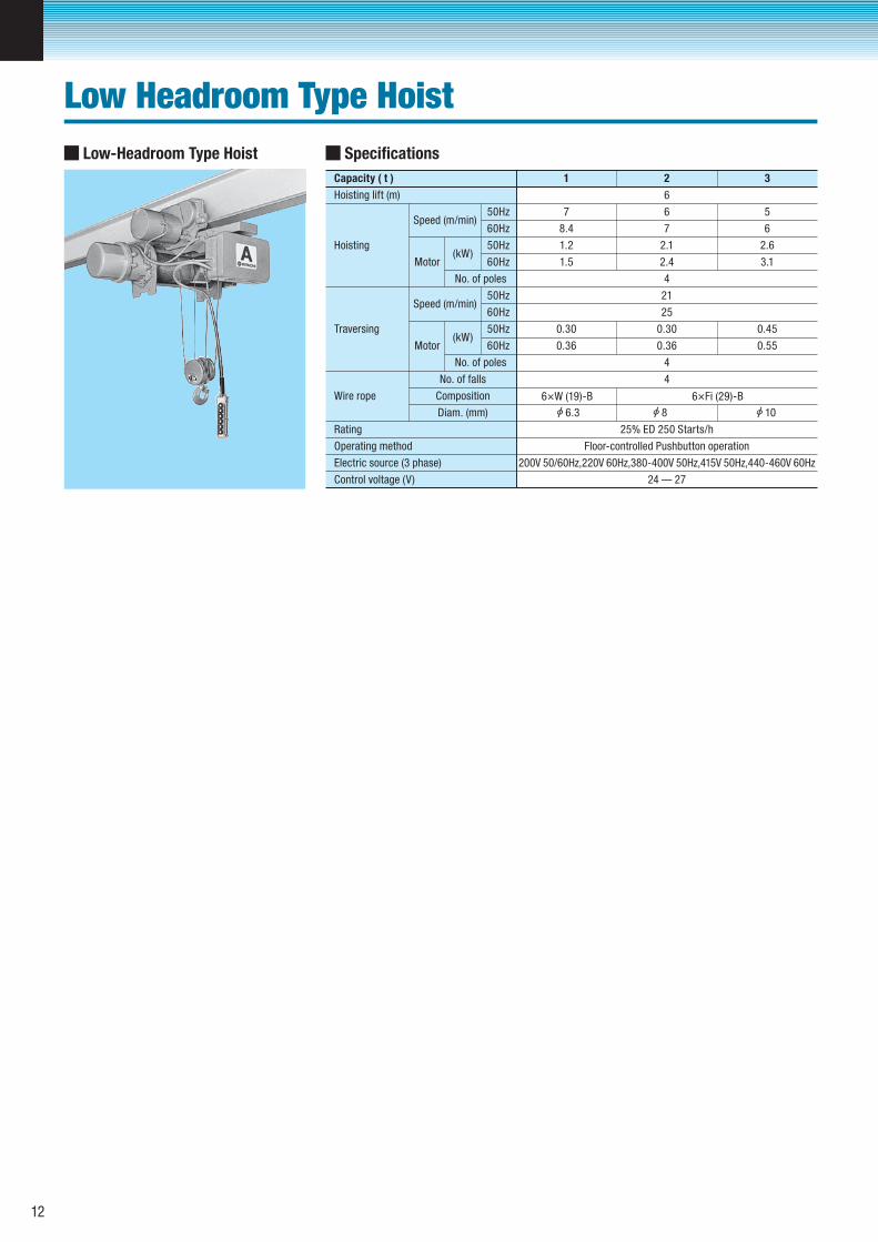
Specifications
Capacity ( t )
Speed (m/min)
(kW)Motor
No. of poles
1 2 3
Hoisting lift (m)
7
6 and 12
6 5
Hoisting
Wire rope
No. of falls
Composition
Diam. (mm)
8.4
1.2
1.5
50Hz
50Hz
60Hz
60Hz
7
2.1
2.4
4
21
25
0.30
0.36
4
2
6×Fi (29)-B
25% ED 250 Starts/h
Floor-controlled Pushbutton operation
200V 50/60Hz,220V 60Hz,380-400V 50Hz,415V 50Hz,440-460V 60Hz
24 – 27
6
2.6
3.1
0.30 0.45
0.36 0.55
11.2 148
Speed (m/min)
(kW)Motor
No. of poles
Traversing
50Hz
50Hz
60Hz
60Hz
Rating
Operating method
Electric source (3 phase)
Control voltage (V)
Standard - Headroom Type Hoist
Table of Dimensions
Model 1AM6 1HAM6 2AM7 2HAM7 3AM6 3HAM6
Capacity ( t ) 1
6,000 12,000
480 650
350 385
85 115
20 90
47 217
47 80
L
A
H
B
M
710
200
26
139
345
255
45
23
32.5
35 40
294 497
115 125
Approx.
dimensions
( mm )
E
N
F
a
J
K
O
R
Q
S
C
t
G
P
U
9
390
120
28
10
2
6,000 12,000
545 580
435 615
75 100
30 110
56 91
58 237
910
200
36
139
400
220
56
36
35.5
35
314 528
190 210
9
500
120
28
10
3
6,000 12,000
565 605
460 640
80 110
35 120
65 106
79 262
1,050
200
36
164
460
245
71
42
41.5
35
344 568
230 255
9
555
180
35
14
Approx. weight ( kg )
Push-buttonindication
Dimensions
Suspension Type Hoist
d
X
1t
2, 3t
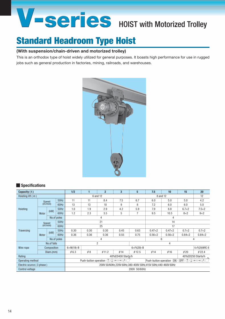
This is an orthodox type of hoist widely utilized for general purposes. It boasts high performance for use in rugged
jobs such as general production in factories, mining, railroads, and warehouses.
Standard Headroom Type Hoist
HOIST with Motorized Trolley
(With suspension/chain-driven and motorized trolley)
10
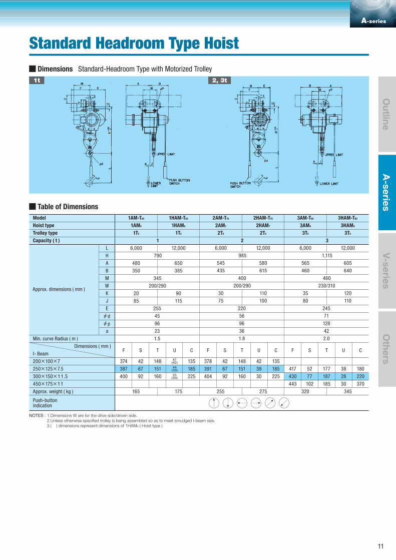
NOTES : 1.Dimensions W are for the drive side/driven side. 2.Unless otherwise specified trolley is being assembled so as to meet smudged I-beam size. 3.( ) dimensions represent dimensions of 1HAM6 ( Hoist type )
Table of Dimensions
Trolley type 1T5
1AM6
1T5 2T5
Capacity ( t )
6,000
1
790
2
12,000
a
480
350
L
A
H
B
650
385
345
200/290
90
115
45
255
96
23
F
374
387
20
85
1.5
Approx. dimensions ( mm )W
M
J
K
E
Dimensions ( mm )
Min. curve Radius ( m )
I- Beam
200×100×7
250×125×7.5
400
S
42
67
92
T
148
151
160
U
47(42)
44(39)
35(30)
C
135
185
225
F
378
391
404
S
42
67
92
T
148
151
160
U
42
39
30
C
135
185
225300×150×11.5
450×175×11175165Approx. weight ( kg )
Push-button indication
6,000
985
12,000
545
435
580
615
400
200/290
110
100
56
220
96
36
30
75
1.8
F
417
430
443
S
52
77
102
T
177
187
185
U
38
28
30
C
180
220
370
6,000
1,115
12,000
565
460
605
640
460
230/310
120
110
71
245
128
42
35
80
2.0
275255 345320
2T5 3T5
Hoist type 1HAM6 3AM6
Model 1HAM-T65 3AM-T65
3T5
1AM-T65 2AM-T75 2HAM-T75 3HAM-T65
2AM7 2HAM7 3HAM6
3
d
p
Dimensions Standard-Headroom Type with Motorized Trolley
1t 2, 3t
A-series
Standard Headroom Type Hoist
A-series
Outline
V-seriesO
thers
11
Specifications
Capacity ( t )
Speed (m/min)
(kW)Motor
No. of poles
1 2 3
Hoisting lift (m)
7
6
6 5
Hoisting
Wire rope
No. of falls
Composition
Diam. (mm)
8.4
1.2
1.5
50Hz
50Hz
60Hz
60Hz
7
2.1
2.4
4
21
25
0.30
0.36
4
4
6×Fi (29)-B6×W (19)-B
25% ED 250 Starts/h
Floor-controlled Pushbutton operation
200V 50/60Hz,220V 60Hz,380-400V 50Hz,415V 50Hz,440-460V 60Hz
24 – 27
6
2.6
3.1
0.30 0.45
0.36 0.55
8 106.3
Speed (m/min)
(kW)Motor
No. of poles
Traversing
50Hz
50Hz
60Hz
60Hz
Rating
Operating method
Electric source (3 phase)
Control voltage (V)
Low-Headroom Type Hoist
Low Headroom Type Hoist
12
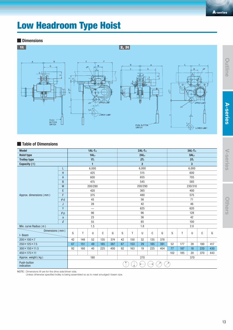
NOTE : Dimensions W are for the drive side/driven side. Unless otherwise specified trolley is being assembled so as to meet smudged I-beam size.
Table of Dimensions
Trolley type 1T5
1AL5
2T5
Capacity ( t )
6,000
1
425
2
a
ℓ
600
475
L
A
H
B
420
200/290
–
28
96
23
42
67
375
45
1.5
Approx. dimensions ( mm )
E
W
F
J
Y
Dimensions ( mm )
Min. curve Radius ( m )
I- Beam
200×100×7
250×125×7.5
92
148
151
160
52
49
40
135
185
225
GS T U C GS T U C GS T U C
374
387
400
42
67
92
150
153
163
32
29
19
135
185
225
378
391
404300×150×11.5
450×175×11
180Approx. weight ( kg )
Push-button indication
6,000
515
655
545
365
200/290
625
42
96
36
480
56
1.8
52
77
102
177
187
185
28
18
20
180
220
370
417
430
443
6,000
600
705
585
400
230/310
620
46
128
42
55 85 100
575
71
2.0
270 370
3T5
Hoist type 3AL5
Model 1AL-T55 2AL-T55 3AL-T55
2AL5
3
d
p
Dimensions
1t 2, 3t
A-series
Low Headroom Type Hoist
A-series
Outline
V-seriesO
thers
13
Specifications
Speed(m/min)
Speed(m/min)
(kW)Motor
Motor
No.of poles
11
Hoisting
Wire rope
No.of falls
Composition
Diam.(mm)
13
1.0
1.2
11
13
1.9
2.3
8.4
10
2.9
3.5
7.5
9
4.2
5
6.7
8
5.9
7
6.0
7.2
7.9
9.5
5.0
6.0
8.8
10.5
5.0
6.0
6.7×2
8×2
4.2
5.0
7.5×2
9×2
50Hz
50Hz
60Hz
60Hz
4
21
25
4
2
6×W(19)-B 6×Fi(29)-B 6×Fi(29)IWRC-B
40%ED400 Starts/h 40%ED250 Starts/h
Push-button operation ↑ ↓ ← → 200V 50/60Hz,220V 60Hz,380-400V 50Hz,415V 50Hz,440-460V 60Hz
200V 50/60Hz
0.30
0.36
0.30
0.36
0.30
0.36
0.45
0.55
0.63
0.75
0.47×2
0.56×2
0.47×2
0.56×2
0.7×2
0.84×2
0.7×2
0.84×2
6.3 8 11.2 14 12.5 14 16 20 22.4
(kW)
No.of poles
Traversing
50Hz
50Hz
60Hz
60Hz
Rating
Operating method
Electric scurce ( 3 phase )
Control voltage
Hoisting lift ( m ) 6 and 12 8 and 12 12
Capacity ( t ) 1 7.5 10 151/2 2 3 5 20
4
14
17
6 4
4
→→ Push-button operation ON OFF ↑ ↓ ← → →
→
This is an orthodox type of hoist widely utilized for general purposes. It boasts high performance for use in rugged
jobs such as general production in factories, mining, railroads, and warehouses.
Standard Headroom Type Hoist
HOIST with Motorized Trolley
(With suspension/chain-driven and motorized trolley)
14
NOTES : 1. Dimensions W represent dimensions of drive side/driven side. 2. 1/2 ton-When an I-beam ( 150×75×5.5 ) is used, the minimum curve radius is 5m. 3. 1/2 ton-When an I-beam ( 150×75×5.5 ) is used, 50mm-thick shims are necessary between the building and the I-beam. 4. Unless otherwise specified trolley is being assembled so as to meet smudged I-beam size. 5. ( ) dimensions represent dimensions of 1/2HM6 and 1HM6 ( Hoist type )
Table of Dimensions
Trolley type
M
Capacity ( t )
6,000
1/2
Approx.
dimensions
( mm )
740
485
355
20
80
12,000
655
380
100
105
L
A
H
B
335
200/290
40
96
21
1.3(5.0)
6,000
790
1 2 3 5
545
350
20
85
12,000
715
385
90
115
345
200/290
45
96
23
1.5
6,000
985
595
435
30
75
12,000
630
615
110
100
415
200/290
56
96
36
1.8
6,000
1,115
645
475
35
80
12,000
690
660
120
110
460
230/310
71
128
42
2.0
8,000
1,190
845
690
12,000
955
800
455
250/330
90
156/140(DRIVE SIDE/DRIVEN SIDE)
58
3.0
E F S T U C E F S T U C E F S T U C E F S T U C E F S T U C
W
J
K
a
Dimensions with respect to I-beam
Min. curve radius ( m )
(150×75×5.5)
200×100×7
250×125×7.5
300×150×11.5
450×175×11
Approx. weight ( kg )
Hoist type
Model 1/2M-T65
1/2M6
1/2T5 1/2T5 1T5 1T5 2T5 2T5 3T5 3T5 5T5 5T5
1/2HM6 1M6 1HM6 2M7 2HM7 3M6 3HM6 5M5 5HM5
1/2HM-T65 1M-T65 1HM-T65 2M-T75 2HM-T75 3M-T65 3HM-T65 5M-T55 5HM-T55
190
190
190
361
374
387
17
42
67
147
148
151
53(43)
52(42)
49(39)
47(42)
44(39)
35(30)
85
135
185
255
255
255
374
387
400
42
67
92
148
151
160
135
185
225
220
220
220
378
391
404
42
67
92
148
151
160
42
39
30
135
185
225
245
245
245
417
430
443
52
77
102
177
187
185
38
28
30
180
220
370
305
305
450
463
77
102
225
223
30
32
215
365
145 155 175 195 280 310 385 415 685 745
d
p
V-series
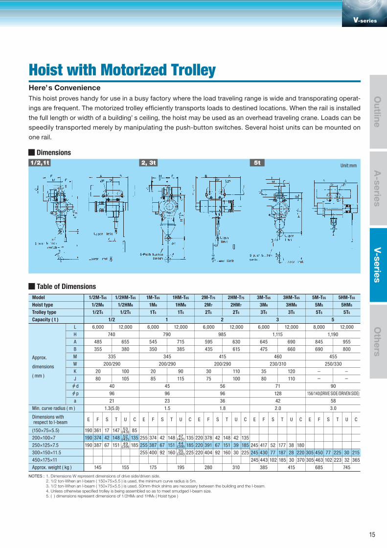
This hoist proves handy for use in a busy factory where the load traveling range is wide and transporating operat-
ings are frequent. The motorized trolley efficiently transports loads to destined locations. When the rail is installed
the full length or width of a building’ s ceiling, the hoist may be used as an overhead traveling crane. Loads can be
speedily transported merely by manipulating the push-button switches. Several hoist units can be mounted on
one rail.
Hoist with Motorized TrolleyHere’s Convenience
1/2,1t 2, 3t 5t
Dimensions
Unit:mm A-series
Outline
V-seriesO
thers
15
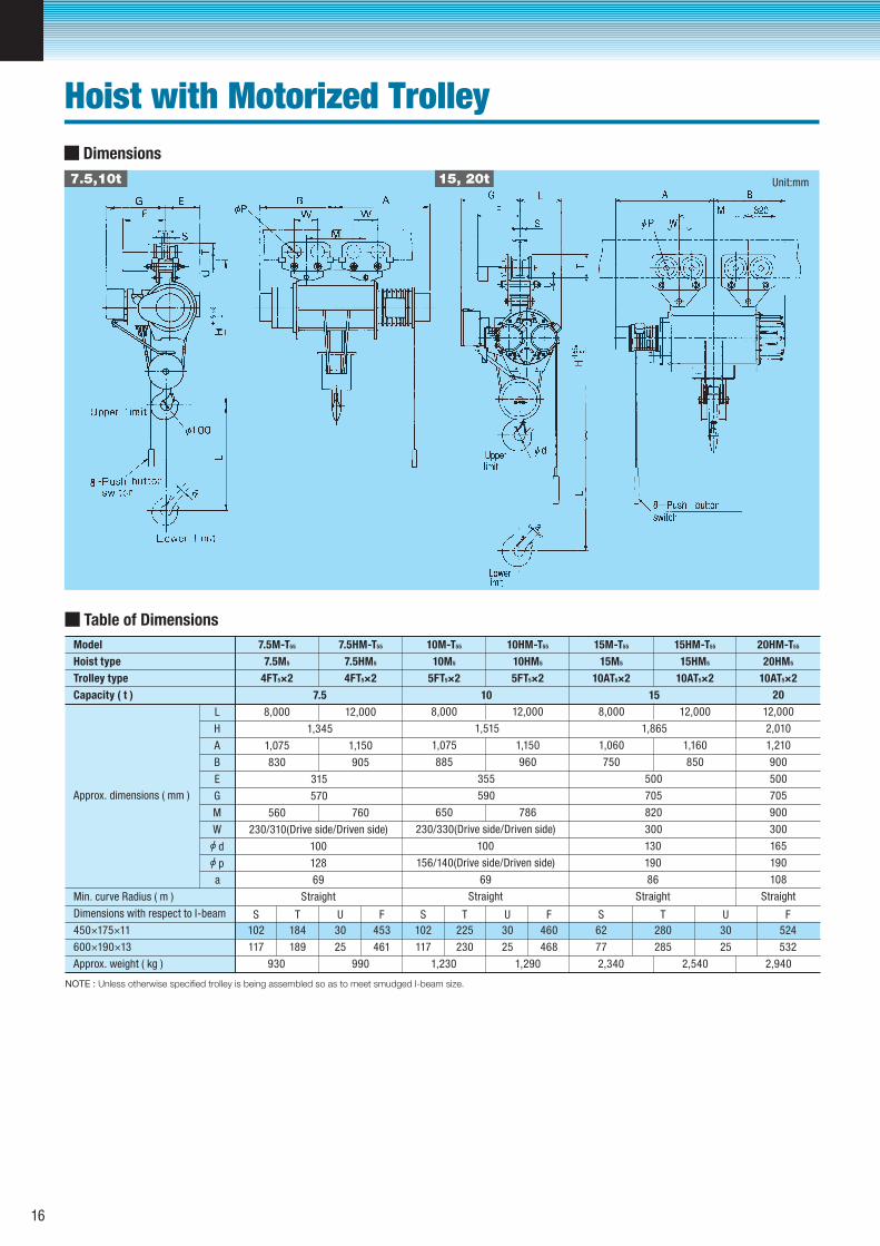
Dimensions
7.5,10t 15, 20t
NOTE : Unless otherwise specified trolley is being assembled so as to meet smudged I-beam size.
Table of Dimensions
Trolley type 4FT5×2
7.5M5
4FT5×2 5FT5×2
Capacity ( t )
8,000
7.5
1,345
10
12,000
a
1,075
830
L
A
H
B
1,150
905
315
570
760
128
100
230/310(Drive side/Driven side)
69
Straight
S
102
117
T
184
189
U
30
25
F
453
461
560
Approx. dimensions ( mm ) G
E
W
M
Min. curve Radius ( m )
Dimensions with respect to I-beam
450×175×11
600×190×13
990930Approx. weight ( kg )
8,000
1,515
12,000
1,075
885
1,150
960
355
590
786
156/140(Drive side/Driven side)
100
230/330(Drive side/Driven side)
69
Straight
650
8,000
1,865
12,000
1,060
750
1,160
850
500
705
820
300
190
130
86
Straight
S
102
117
T
225
230
U
30
25
F
460
468
S
62
77
T
280
285
U
30
25
F
524
532
1,2901,230 2,5402,340
5FT5×2 10AT5×2
Hoist type 7.5HM5 15M5
Model 7.5HM-T55 15M-T55
10AT5×2
7.5M-T55 10M-T55 10HM-T55 15HM-T55
10M5 10HM5 15HM5
15
12,000
Unit:mm
20
1,210
2,010
900
900
705
500
300
165
190
108
Straight
2,940
10AT5×2
20HM-T55
20HM5
d
p
Hoist with Motorized Trolley
16
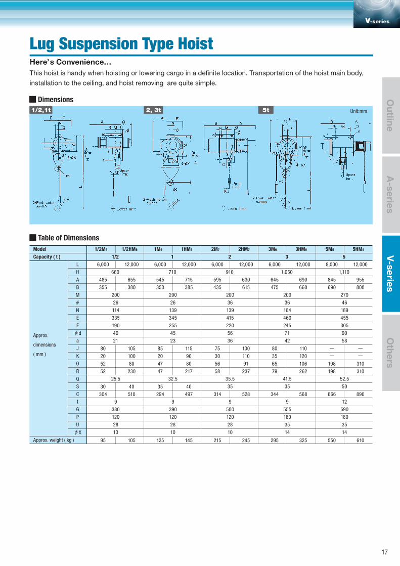
This hoist is handy when hoisting or lowering cargo in a definite location. Transportation of the hoist main body,
installation to the ceiling, and hoist removing are quite simple.
Lug Suspension Type HoistHere’s Convenience…
1/2,1t 2, 3t 5t
Dimensions
Table of Dimensions
M
Capacity ( t )
6,000
Approx.
dimensions
( mm )
660
1/2
485
355
12,000
655
380
L
A
H
B
200
26
114
335
190
40
21
25.5
9
380
120
28
10
E
F
N
a
J
K
O
R
Q
S
C
t
G
P
U
Approx. weight ( kg )
Model 1/2M6 1/2HM6 1M6 1HM6 2M7 2HM7 3M6 3HM6 5M5 5HM5
80
20
105
100
52 80
52 230
30 40
304 510
95 105
6,000
710
1 2 3 5
545
350
12,000
715
385
200
26
139
345
255
45
23
32.5
9
390
120
28
10
85
20
115
90
47 80
47 217
35 40
294 497
125 145
6,000
910
595
435
12,000
630
615
200
36
139
415
220
56
36
35.5
35
9
500
120
28
10
75
30
100
110
56 91
58 237
314 528
215 245
6,000
1,050
645
475
12,000
690
660
200
36
164
460
245
71
42
41.5
35
9
555
180
35
14
80
35
110
120
65 106
79 262
344 568
295 325
8,000
1,110
845
690
12,000
955
800
270
46
189
455
305
90
58
52.5
50
12
590
180
35
14
198 310
198 310
666 890
550 610
d
X
Unit:mm
V-series
A-series
V-seriesO
utlineO
thers
17
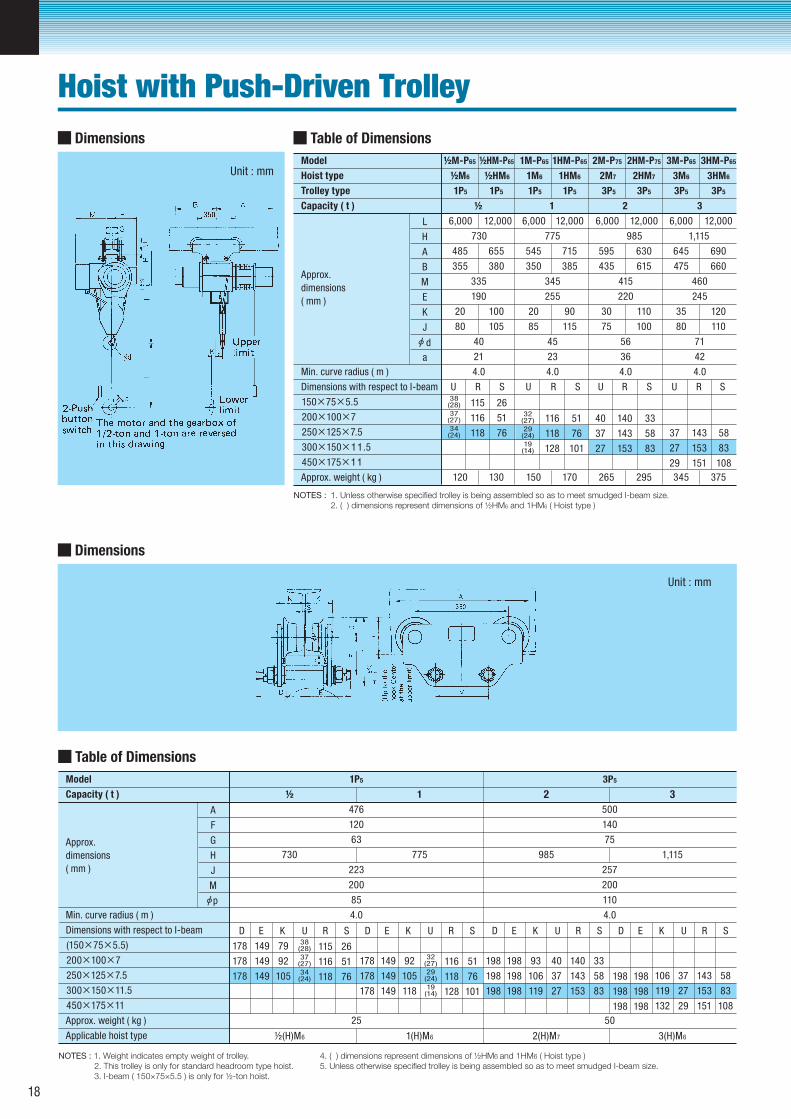
Table of Dimensions
Model ½M-P65 ½HM-P65 1M-P65 1HM-P65 2M-P75 2HM-P75 3M-P65 3HM-P65
Hoist type
Trolley type
Capacity ( t )
1P5 1P5 1P5 1P5 3P5 3P5 3P5 3P5
½M6 ½HM6 1M6 1HM6 2M7 2HM7 3M6 3HM6
Min. curve radius ( m )
½ 1 2 3
6,000 12,000 6,000 12,000 6,000 12,000 6,000 12,000
730 775 985 1,115
485 655 545 715 595 630 645 690
355 380 350 385 435 615 475 660
20 100 20 90 30 110 35 120
80 105 85 115 75 100 80 110
120 130 150 170 265 295 345 375
335 345 415 460
40 45 56 71
21 23 36 42
4.0 4.0 4.0 4.0
190 255 220 245
U R S U R S U R S U R S
11538
(28) 26
11637
(27) 51
11834(24) 76
11632
(27) 51
11829
(24) 76
12819
(14) 101
40
37
27
140
143
153
33
58
83
37
27
29
143
153
151
58
83
108
Approx.
dimensions
( mm )
Dimensions with respect to I-beam
Approx. weight ( kg )
Unit : mm
Unit : mm
Dimensions
Dimensions
NOTES : 1. Unless otherwise specified trolley is being assembled so as to meet smudged I-beam size. 2. ( ) dimensions represent dimensions of ½HM6 and 1HM6 ( Hoist type )
200×100×7
150×75×5.5
250×125×7.5
300×150×11.5
450×175×11
L
A
H
B
E
M
K
J
a
d
Table of Dimensions
Model 1P5 3P5
Capacity ( t )
476 500
½ 1 2 3
Min. curve radius ( m )
120 140
63 75
730 775 985 1,115
223 257
200 200
25 50
½(H)M6 1(H)M6 2(H)M7 3(H)M6
85 110
4.0 4.0
D E K U R S D E K U R S D E K U R S D E K U R S
149 79
149 92
149
178
178
178 105
11538
(28) 26
11637
(27) 51
11834(24) 76
149
149
92
149
178
178
178
105
118
93198
198
198
198
198
198
198
198
198
198
198
198
106
119
140
143
33
153
40
37
27
58
83
106
119
132
143
153
58
151
37
27
29
83
108
11632
(27) 51
11829
(24) 76
12819
(14) 101
Approx.
dimensions
( mm )
Dimensions with respect to I-beam
Approx. weight ( kg )
Applicable hoist type
200×100×7
(150×75×5.5)
250×125×7.5
300×150×11.5
450×175×11
A
G
F
H
M
J
p
NOTES : 1. Weight indicates empty weight of trolley.2. This trolley is only for standard headroom type hoist.3. I-beam ( 150×75×5.5 ) is only for ½-ton hoist.
4. ( ) dimensions represent dimensions of ½HM6 and 1HM6 ( Hoist type )5. Unless otherwise specified trolley is being assembled so as to meet smudged I-beam size.
Hoist with Push-Driven Trolley
18
Unit : mm
Unit : mm
2 3
Table of Dimensions
Model ½M-C65 ½HM-C65 1M-C65 1HM-C65 2M-C75 2HM-C75 3M-C65 3HM-C65
Hoist type
Trolley type
Capacity ( t )
½C5 1C5 3C5 3C5
½M6 ½HM6 1M6 1HM6 2M7 2HM7 3M6 3HM6
Min. curve radius ( m )
½ 1 2 3
6,000 12,000 6,000 12,000 6,000 12,000 6,000 12,000
715 775 985 1,115
485 655 545 715 595 630 645 690
355 380 350 385 435 615 475 660
20 100 20 90 30 110 35 120
80 105 85 115 75 100 80 110
145 155 165 185 290 320 370 400
335 345 415 460
40 45 56 71
21 23 36 42
4.04.04.01.3
6,300 12,800 6,300 12,800 6,200 12,700 6,200 12,700
190 255 220 245
189/240 189/350 231/350 231/350
F G S T U R F G S T U R F G S T U R F G S T U R
33728(18)
35027
(17)
363
247
260
273
120
121
124
133
134
13724
(14)
26
51
76
35032
(27)
36329
(24)
376
–
–
–
121
124
134
134
137
14719
(14)
51
76
101
366
379
392
–
–
–
150
153
163
188
200
210
33
58
83
40
37
27
379
392
–
–
153
163
200
210
58
83
37
27
405 – 161 208108 29
Approx.
dimensions
( mm )
Dimensions with respect to I-beam
Approx. weight ( kg )
Dimensions
Dimensions
NOTES : 1. ( ) dimensions represent dimensions of ½HM6 and 1HM6 ( Hoist type ) 2. Unless otherwise specified trolley is being assembled so as to meet smudged I-beam size.
200×100×7
150×75×5.5
250×125×7.5
300×150×11.5
450×175×11
L
A
H
B
E
W
M
K
J
a
N
d
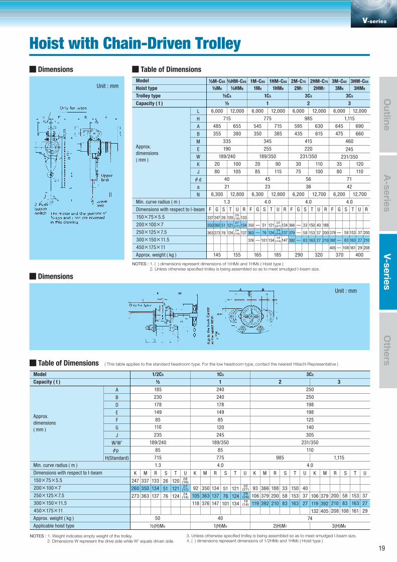
Table of Dimensions ( This table applies to the standard headroom type. For the low headroom type, contact the nearest Hitachi Representative ) Model 1/2C5 3C51C5
Capacity ( t )
185 250240
½ 1 2 3
Min. curve radius ( m )
230 240 250
178 178 198
149 149 198
85 125
110 140
50 40 74
½(H)M6 1(H)M6 2(H)M7 3(H)M6
235 305
189/240
85
120
245
189/350 231/350
85 85 110
715 775 985 1,115
1.3 4.0 4.0
K M R S T U K M R S T U K M R S T U K M R S T U
337 133
350 134
363
247
260
273 137
12028(18)26
12127
(17)51
12424
(14)76
350
363
134
376
92
105
118
137
147
18893
106
119
366
379
392
106
119
132
379
392
405
200
210
150
153
40
163
33
58
83
37
27
200
210
208
153
163
37
161
58
83
108
27
29
12151
12476
134
32(27)
29(24)
19(14)101
Approx.
dimensions
( mm )
Dimensions with respect to I-beam
Approx. weight ( kg )
Applicable hoist type
200×100×7
150×75×5.5
250×125×7.5
300×150×11.5
450×175×11
A
D
B
E
G
J
W/W’
H(Standard)
F
p
NOTES : 1. Weight indicates empty weight of the trolley. 2. Dimensions W represent the drive side while W’ equals driven side.
3. Unless otherwise specified trolley is being assembled so as to meet smudged I-beam size. 4. ( ) dimensions represent dimensions of 1/2HM6 and 1HM6 ( Hoist type )
V-series
Hoist with Chain-Driven Trolley
A-series
Outline
V-seriesO
thers
19
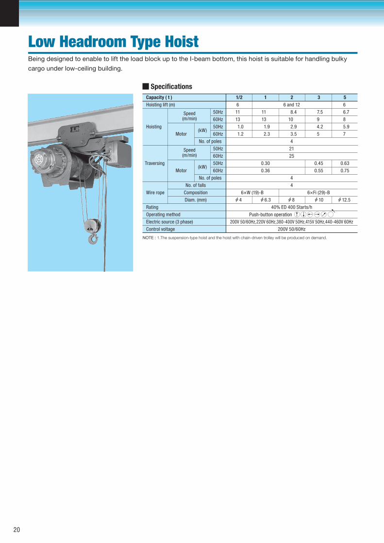
Specifications
Capacity ( t )
Speed(m/min)
(kW)Motor
Motor
No. of poles
11/2 2 3 5
Hoisting lift (m)
11
6 6 and 12
8.4 6.7
6
Hoisting
Wire rope
No. of falls
Composition
Diam. (mm)
13
1.0
1.2
50Hz
50Hz
60Hz
60Hz
10
2.9
3.5
4
21
25
0.45
0.55
4
4
6×Fi (29)-B6×W (19)-B
40% ED 400 Starts/h
200V 50/60Hz,220V 60Hz,380-400V 50Hz,415V 50Hz,440-460V 60Hz
200V 50/60Hz
8
5.9
7
0.30 0.63
0.36 0.75
86.3 10
11
13
1.9
2.3
12.54
Speed(m/min)
(kW)
No. of poles
Traversing
50Hz
50Hz
60Hz
60Hz
Rating
Operating method
Electric source (3 phase)
Control voltage
7.5
9
4.2
5
NOTE : 1.The suspension-type hoist and the hoist with chain-driven trolley will be produced on demand.
Push-button operation ↑ ↓ ← → →→
Being designed to enable to lift the load block up to the I-beam bottom, this hoist is suitable for handling bulky
cargo under low-ceiling building.
Low Headroom Type Hoist
20
Unit : mm Unit : mm
Unit : mm Unit : mm
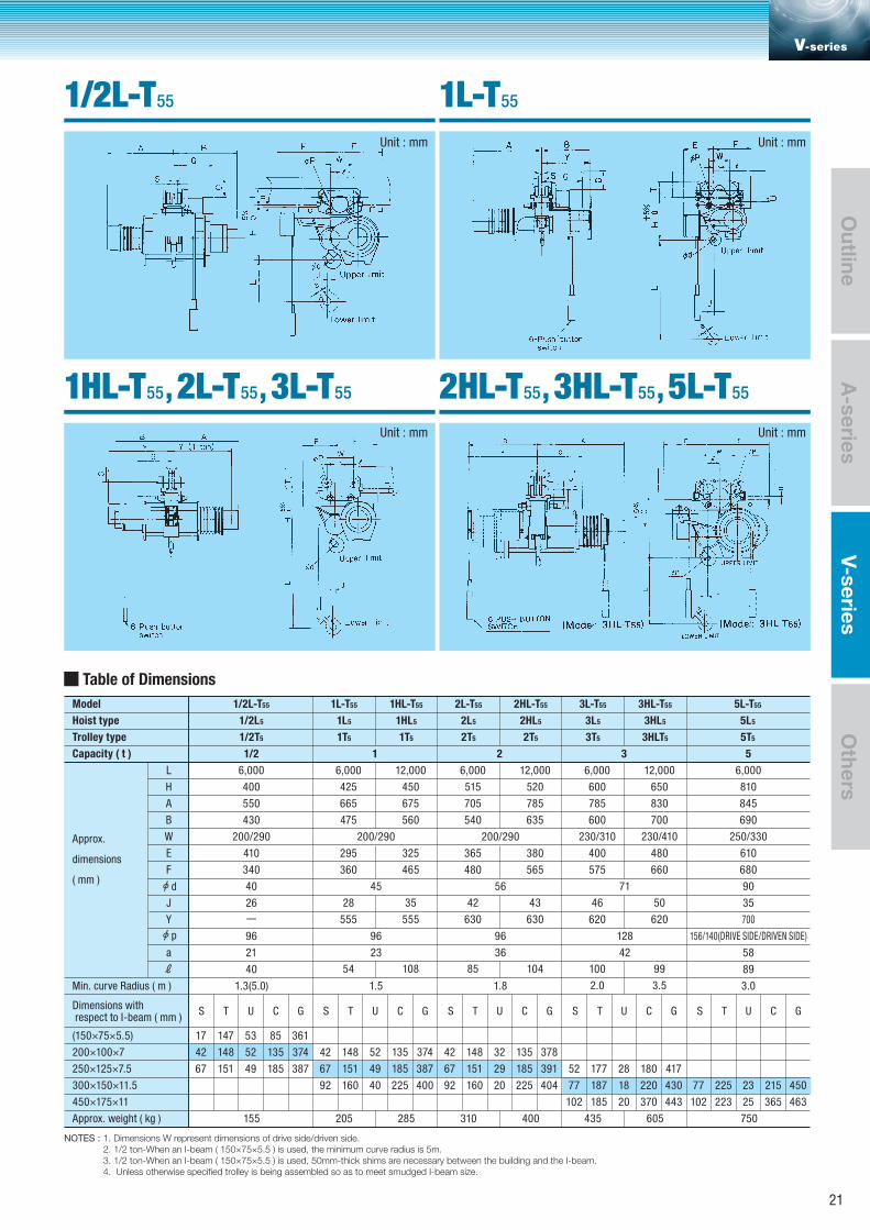
NOTES : 1. Dimensions W represent dimensions of drive side/driven side. 2. 1/2 ton-When an I-beam ( 150×75×5.5 ) is used, the minimum curve radius is 5m. 3. 1/2 ton-When an I-beam ( 150×75×5.5 ) is used, 50mm-thick shims are necessary between the building and the I-beam. 4. Unless otherwise specified trolley is being assembled so as to meet smudged I-beam size.
Table of Dimensions
Trolley type
W
Capacity ( t )
6,000
1/2
400
Approx.
dimensions
( mm )
550
430
340
40
L
A
H
B
200/290
410
26
96
21
40
1.3(5.0)
6,000
1 2 3 5
665
475
295
360
12,000
675
560
325
465
200/290
45
96
1.5
6,000
705
540
365
480
12,000
785
635
380
565
200/290
56
96
1.8
6,000
785
600
400
575
12,000
425 450 515 520 600 650
830
700
230/310 230/410
480
660
71
128
23 36 42
810
845
690
680
90
6,000
250/330
610
35
700
156/140(DRIVE SIDE/DRIVEN SIDE)
58
89
3.0
UTS TS TS TS TSC G
E
J
F
Y
a
ℓ
Dimensions with respect to I-beam ( mm )
Min. curve Radius ( m )
(150×75×5.5)
200×100×7
250×125×7.5
300×150×11.5
450×175×11
Approx. weight ( kg )
Hoist type
Model 1/2L-T55
1/2L5
1/2T5 1T5 1T5 2T5 2T5 3T5 3HLT5 5T5
1L5 1HL5 2L5 2HL5 3L5 3HL5 5L5
1L-T55 1HL-T55 2L-T55 2HL-T55 3L-T55 3HL-T55 5L-T55
17
42
67
28
555
35
555
42
630
43
630
46
620
50
620
54 108 85 104 100 99
2.0 3.5
147
148
151
53
52
49
85
135
185
361
374
387
U C G
42
67
148
151
52
49
135
185
374
387
U C G
42
67
148
151
32
29
135
185
378
391
U C G
52 177 28 180 417
U C G
92 160 40 225 400 92 160 20 225 404 77 187 18 220 430 77 225 23 215 450
102 185 20 370 443 102 223 25 365 463
155 205 285 310 400 435 605 750
d
p
V-series
1/2L-T55
1HL-T55, 2L-T55, 3L-T55
1L-T55
2HL-T55, 3HL-T55, 5L-T55
A-series
Outline
V-seriesO
thers
21
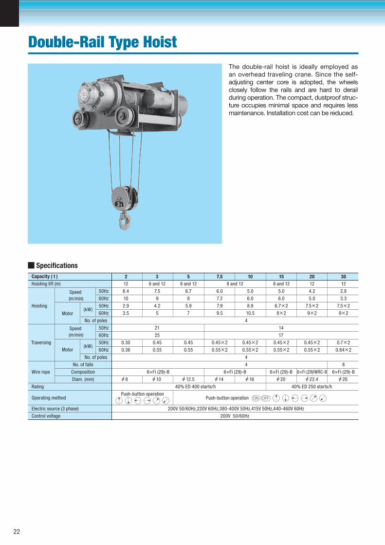
The double-rail hoist is ideally employed as an overhead traveling crane. Since the self- adjusting center core is adopted, the wheels closely follow the rails and are hard to derail during operation. The compact, dustproof struc-ture occupies minimal space and requires less maintenance. Installation cost can be reduced.
Specifications
Capacity ( t )
Speed
(m/min)
(kW)Motor
No. of poles
2 3 5 7.5 10 15 20 30
Hoisting lift (m)
8.4
6 and 1212 12128 and 12 8 and 12 8 and 12
7.5 6.7 6.0 5.0 5.0 4.2 2.8
Hoisting
Wire rope
No. of falls
Composition
Diam. (mm)
10
2.9
3.5
50Hz
50Hz
60Hz
60Hz
9
4.2
5
4
21 14
25 17
4
4 8
6×Fi (29)-B 6×Fi (29)-B 6×Fi (29)-B 6×Fi (29)IWRC-B 6×Fi (29)-B
40% ED 400 starts/h 40% ED 250 starts/h
Push-button operation
200V 50/60Hz,220V 60Hz,380-400V 50Hz,415V 50Hz,440-460V 60Hz
200V 50/60Hz
8 7.2 6.0 6.0 5.0 3.3
5.9 7.9 8.8 6.7×2 7.5×2 7.5×2
7 9.5 10.5 8×2 9×2 9×2
0.30 0.450.45
0.36 0.55
0.45×2
0.55×2
0.45×2
0.55×2
0.45×2
0.55×2
0.45×2
0.55×2
0.7×2
0.84×20.55
10 14 16 20 22.4 2012.58
Speed
(m/min)
(kW)Motor
No. of poles
Traversing
50Hz
50Hz
60Hz
60Hz
Rating
Operating method
Electric source (3 phase)
Control voltage
Push-button operation ON OFF
Double-Rail Type Hoist
22
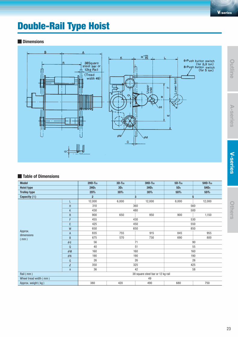
Dimensions
Table of Dimensions
Model 2HD-T55 3HD-T553D-T55 5HD-T555D-T55
Hoist type
Trolley type
Capacity ( t )
12,000
310
430
900
455
425
650
835
675
56
40
160
190
26
350
36
8,000
900
845
690
12,000
1,150
955
800
6,000
650
755
570
12,000
950
915
730
2HD5 3D5 3HD5 5HD55D5
2DT5
2 3 5
3DT5 3DT5 5DT55DT5
Rail ( mm )
360
480
430
450
650
71
51
160
190
26
325
42
380 420 490 680 750
49
38 square steel bar or 12 kg rail
Approx.
dimensions
( mm )
Wheel tread width ( mm )
Approx. weight ( kg )
L
K
H
R
E
W
A
B
Q
G
ℓa
F
N
M
d
4 8
560
500
530
550
850
90
55
160
190
26
425
58
V-series
Double-Rail Type Hoist
A-series
Outline
V-seriesO
thers
23
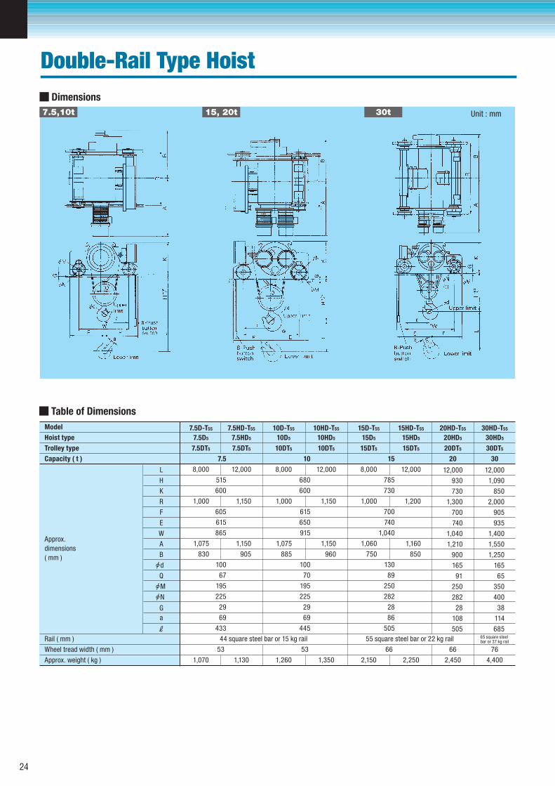
7.5,10t 15, 20t 30t
Dimensions
Table of Dimensions Model 7.5D-T55 10D-T557.5HD-T55 10HD-T55 15D-T55 15HD-T55 20HD-T55 30HD-T55
Hoist type
Trolley type
Capacity ( t )
8,000
1,000
1,075
830
8,000
1,000
1,060
750
12,000
1,090
850
2,000
905
935
1,400
1,550
1,250
165
65
350
400
38
114
685
12,000
930
730
1,300
700
740
1,040
1,210
900
165
91
250
282
28
108
505
12,000
1,150
1,150
905
12,000
1,200
1,160
850
8,000
1,000
1,075
885
12,000
1,150
1,150
960
7.5D5 7.5HD5 10D5 10HD5 15HD5 20HD5 30HD515D5
7.5DT5 7.5DT5
7.5
515
600
605
615
865
100
67
195
225
29
69
433
10
680
600
615
650
915
100
70
195
225
29
69
445
15
785
730
700
740
1,040
130
89
250
282
28
86
505
20 30
10DT5 10DT5 15DT5 20DT5 30DT515DT5
Rail ( mm )
1,070 1,130 1,260 1,350 2,150 2,250 2,450 4,400
53 53 66 66 76
44 square steel bar or 15 kg rail 55 square steel bar or 22 kg rail 65 square steel bar or 37 kg rail
Approx.
dimensions
( mm )
Wheel tread width ( mm )
Approx. weight ( kg )
L
K
H
R
E
W
A
B
Q
G
ℓa
F
N
M
d
Unit : mm
Double-Rail Type Hoist
24
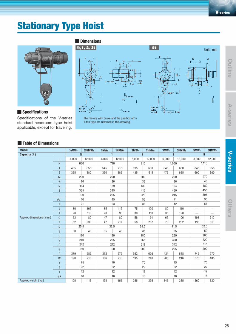
½,1, 2, 3t 5t
Dimensions
Table of Dimensions Model ½MW6 ½HMW6 1MW6 1HMW6 3MW6 3HMW6 5MW5 5HMW52MW7 2HMW7
Capacity ( t )
660
200
26
114
335
190
40
21
25.5
180
240
242
150
75
22
12
18
485
355
80
20
52
52
30
379
190
105
1,110
270
46
189
455
305
90
58
52.5
50
260
320
315
290
75
22
12
18
710
200
26
139
345
255
45
23
32.5
180
265
242
160
70
22
12
18
6,000 12,000 6,000 12,000 6,000 12,000 6,000 12,000 8,000 12,000
1,050
200
36
164
460
245
71
42
41.5
35
260
320
342
225
75
22
12
18
½ 1 2 3 5
910
200
36
139
415
220
56
36
35.5
35
180
265
312
200
70
22
12
18
Approx. dimensions ( mm )
Approx. weight ( kg )
L
A
H
B
N
E
F
a
J
K
O
R
Q
S
U
V
C
G
P
W
Y
Z
t
M
X
d
655
380
105
110
80
230
40
582
218
115
545
350
85
20
47
47
35
372
186
135
715
385
115
90
80
217
40
575
213
155
595
435
75
30
56
58
392
195
255
630
615
100
110
91
237
606
240
295
645
475
80
35
65
79
424
205
345
690
665
110
120
106
262
648
246
385
845
690
–
–
198
198
745
373
560
955
800
–
–
310
310
970
485
620
Specifications
Specifications of the V-series standard headroom type hoist applicable, except for traveling.
The motors with brake and the gearbox of ½,1-ton type are reversed in this drawing.
Unit : mm
V-series
Stationary Type Hoist
A-series
Outline
V-seriesO
thers
25
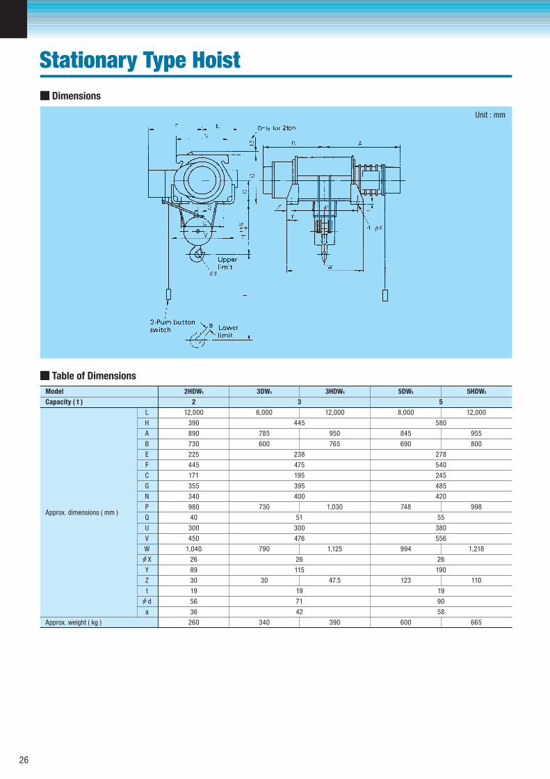
Table of Dimensions
12,000 6,000 12,000
785 950
600 765
730 1,030
790 1,125
30 47.5
340 390
390 445
238
475
195
395
400
51
300
476
26
115
19
71
42
890
Approx. dimensions ( mm )
A
H
L
E
B
F
730
225
445
171
355
340
980
40
300
450
1,040
89
30
19
56
26
G
C
P
N
Q
U
V
W
X
Y
Z
t
a 36
260Approx. weight ( kg )
Capacity ( t ) 2 3
Model 3DW5 3HDW5 5DW5 5HDW52HDW5
8,000 12,000
845 955
690 800
748 998
994 1,218
123 110
600 665
580
278
540
245
485
420
55
380
556
26
190
19
90
58
5
d
Unit : mm
Dimensions
26
Stationary Type Hoist
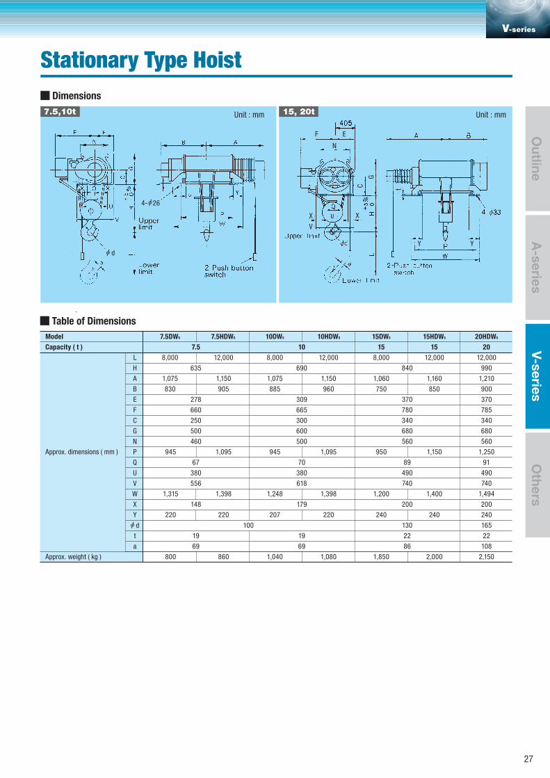
Table of Dimensions
8,000 12,000
1,075 1,150
830 905
945 1,095
1,315 1,398
800 860
635
278
660
250
500
460
67
380
556
148
19
69
Approx. dimensions ( mm )
A
H
L
E
B
F
G
C
P
N
Q
U
V
W
X
Y
t
a
Approx. weight ( kg )
Capacity ( t ) 7.5
Model 7.5DW5 7.5HDW5 10DW5 10HDW5
8,000 12,000
1,075 1,150
885 960
945 1,095
1,248 1,398
1,040 1,080
690
309
665
300
600
500
70
380
618
179
19
100
69
10
220 220 207 220
d
d
F
4- 26
X X
V
u
C t
Y Y
G
E
N
8,000
1,060
750
950
1,200
240
1,850
15DW5
15
12,000
1,160
850
1,150
1,400
240
2,000
840
370
780
340
680
560
89
490
740
200
130
22
86
15HDW5
15
12,000
990
1,210
900
370
785
340
680
560
1,250
91
490
740
1,494
200
240
165
22
108
2,150
20HDW5
20
Unit : mmUnit : mm
Dimensions
7.5,10t 15, 20t
V-series
A-series
Outline
V-seriesO
thers
27
Stationary Type Hoist
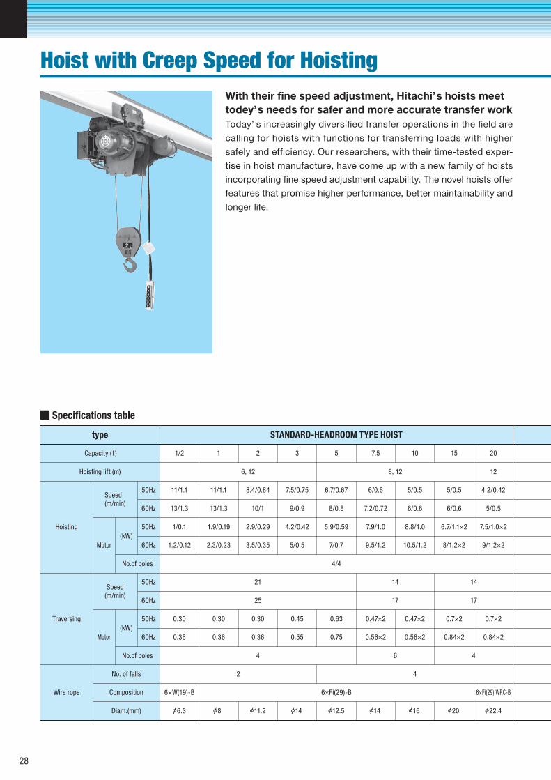
Specifications table
Hoisting lift (m)
Speed(m/min)
(kW)
Motor
No.of poles
6, 12
Hoisting
Wire rope
No. of falls
Composition
Diam.(mm)
50Hz
50Hz
60Hz
60Hz
Speed(m/min)
(kW)
Motor
No.of poles
Traversing
50Hz
50Hz
60Hz
60Hz
8, 12
Capacity ( t ) 1/2 1 2 3 5 7.5 15 20
12
type STANDARD-HEADROOM TYPE HOIST
4/4
10
11/1.1 11/1.1 8.4/0.84 7.5/0.75 6.7/0.67 6/0.6 5/0.5 4.2/0.425/0.5
0.30
6×W(19)-B
0.30 0.30 0.45 0.63
0.36 0.36 0.36 0.55 0.75
0.47×2 0.7×2 0.7×20.47×2
0.56×2 0.84×2 0.84×20.56×2
13/1.3 13/1.3 10/1 9/0.9 8/0.8 7.2/0.72 6/0.6 5/0.56/0.6
1/0.1 1.9/0.19 2.9/0.29 4.2/0.42 5.9/0.59 7.9/1.0 6.7/1.1×2 7.5/1.0×28.8/1.0
1.2/0.12 2.3/0.23 3.5/0.35 5/0.5 7/0.7 9.5/1.2 8/1.2×2 9/1.2×210.5/1.2
21 1414
25
4
1717
46
2 4
6×Fi(29)-B 6×Fi(29)IWRC-B
6.3 8 11.2 14 12.5 14 16 20 22.4
Hoist with Creep Speed for Hoisting
Today’ s increasingly diversified transfer operations in the field are
calling for hoists with functions for transferring loads with higher
safely and efficiency. Our researchers, with their time-tested exper-
tise in hoist manufacture, have come up with a new family of hoists
incorporating fine speed adjustment capability. The novel hoists offer
features that promise higher performance, better maintainability and
longer life.
With their fine speed adjustment, Hitachi’s hoists meettodey’s needs for safer and more accurate transfer work
28
1/2
6
11/1.1
13/1.3
1/0.1
1.2/0.12
1
11/1.1
13/1.3
1.9/0.19
2.3/0.23
0.30 0.30
0.36
6×W(19)-B
0.36
6, 12
8.4/0.84
10/1
2.9/0.29
3.5/0.35
4/4
21
25
0.30
0.36
4
4
2 3 5
6
7.5/0.75 6.7/0.67
9/0.9 8/0.8
4.2/0.42 5.9/0.59
5/0.5 7/0.7
0.45 0.63
0.55 0.75
6×Fi(29)-B
2
12
8.4/0.84
10/1
2.9/0.29
3.5/0.35
0.30
0.36
3
6, 12
7.5/0.75
9/0.9
4.2/0.42
5/0.5
21
25
0.45
0.55
4
4
6×Fi(29)-B
5 7.5 10 15
8, 12
6.7/0.67 6/0.6 5/0.5 5/0.5
8/0.8 7.2/0.72 6/0.6 6/0.6
5.9/0.59 7.9/1 8.8/1 6.7/1×2
7/0.7
0.45
0.55
9.5/1.2
4/4
10.5/1.2 8/1.2×2
20 30
12
4.2/0.42 2.8/0.28
5/0.5 3.3/0.33
7.5/1×2 7.5/1×2
9/1.2×2 9/1.2×2
0.45×2 0.45×2
17
0.45×2
14
0.45×2 0.70×2
0.55×2 0.55×2
6×Fi(29)-B
0.55×2 0.55×2
6×Fi(29)IWRC-B
0.84×2
4 4
8
6×Fi(29)-B
LOW-HEADROOM TYPE HOIST DOUBLE-RAIL TYPE HOIST
2 4
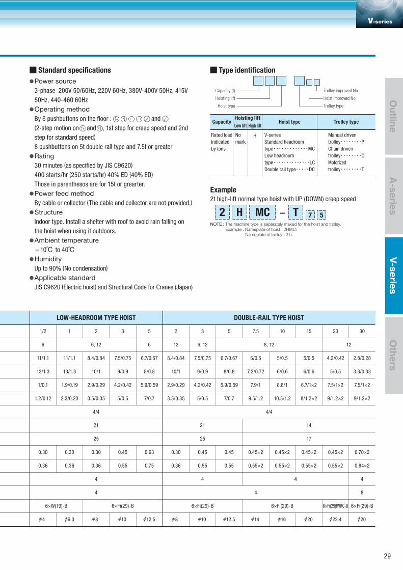
Rated load
indicated
by tons
No
markH V-series
Standard headroom
type・・・・・・・・・・・・・MC
Low headroom
type・・・・・・・・・・・・・・LC
Double rail type・・・・・DC
Manual driven
trolley・・・・・・・・P
Chain driven
trolley・・・・・・・・C
Motorized
trolley・・・・・・・・T
Low lift High liftCapacity
Hoisting liftHoist type Trolley type
4 6.3 8 10 12.5 8 10 12.5 14 16 20 22.4 20
Power source3-phase 200V 50/60Hz, 220V 60Hz, 380V-400V 50Hz, 415V
50Hz, 440-460 60Hz
Operating methodBy 6 pushbuttons on the floor : and
(2-step motion on and , 1st step for creep speed and 2nd
step for standard speed)
8 pushbuttons on 5t double rail type and 7.5t or greater
Rating30 minutes (as specified by JIS C9620)
400 starts/hr (250 starts/hr) 40% ED (40% ED)
Those in parenthesos are for 15t or grearter.
Power feed methodBy cable or collector (The cable and collector are not provided.)
StructureIndoor type. Install a shelter with roof to avoid rain falling on
the hoist when using it outdoors.
Ambient temperature-10℃ to 40℃HumidityUp to 90% (No condensation)
Applicable standardJIS C9620 (Electric hoist) and Structural Code for Cranes (Japan)
Standard specifications Type identification
Trolley typeHoist type
Hoisting lift
Capacity (t)
Hoist improved No.
Trolley improved No.
2t high-lift normal type hoist with UP (DOWN) creep speed
Example
- 572 H MC TNOTE : The machine type is separately maked for the hoist and trolley.
Example : Nameplate of hoist : 2HMC7
Nameplate of trolley : 2T5
V-series
A-series
Outline
V-seriesO
thers
29
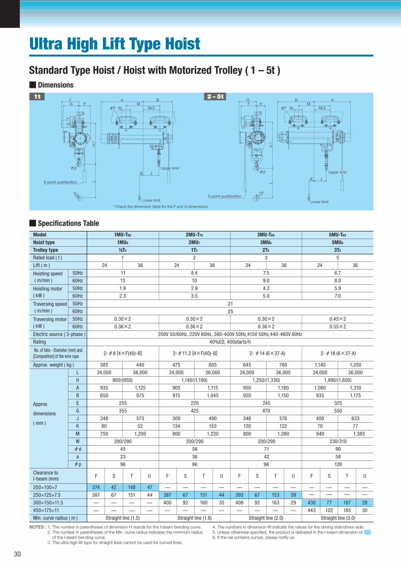
Dimensions
1t 2 – 5t
* Check the dimension table for the F and G dimensions.
Ultra High Lift Type Hoist
NOTES : 1. The number in parentheses of dimension H stands for the I-beam bending curve. 2. The number in parentheses of the Min. curve radius indicates the minimum radius of the I-beam bending curve. 3. The ultra high lift type for straight lines cannot be used for curved lines.
4. The numbers in dimension W indicate the values for the driving side/driven side. 5. Unless otherwise specified, the product is delivered in the I-beam dimension of . 6. If the rail contains curves, please notify us.
Specifications Table
Trolley type
E
Rated load ( t )
24,000
1
Approx.
dimensions
( mm )
900/(950)
935
650
348
80
36,000
1,125
875
573
52
L
A
H
B
255
355
200/290
45
24,000
1,140/(1,190)
2 3
Lift ( m )
Hoisting speed
( m/min )
Hoisting motor
( kW )
Traversing speed
( m/min )
Traversing motor
( kW )
11 8.4 7.5
13 10 9.0
1.9 2.9 4.2
2.3 3.5 5.0
0.30×2 0.30×2
21
25
0.30×2
0.36×2 0.36×2 0.36×2
Electric source ( 3-phase ) 200V 50/60Hz, 220V 60Hz, 380-400V 50Hz,415V 50Hz,440-460V 60Hz
Rating 40%ED, 400starts/h
No. of falls - Diameter (mm) and [Composition] of the wire rope
Approx. weight ( kg )
905
915
300
134
36,000
1,115
1,045
490
153
220
425
200/290
56
24,000
1,250/(1,330)
950
920
346
120
36,000
1,180
1,150
576
122
245
470
200/290
71
24,000
1,080
935
36,000
1,310
1,175
400
70
633
77
750 1,200 800 1,220 800 1,260 940 1,385
23 36 42
96 96 96 128
G
K
M
W
J
50Hz
50Hz
50Hz
60Hz
60Hz
60Hz
60Hz
50Hz
a
Clearance to I-beam (mm)
200×100×7
250×125×7.5
300×150×11.5
450×175×11
Min. curve radius ( m )
Hoist type
Model 1MU-T65
1MU6
½T5 1T5 2T5
2MU7 3MU6
2MU-T75 3MU-T65
385 440 475 605 645 760 1,140 1,250
24 36 24 36 24 36 24 36
F
393
406
S
67
92
T
153
163
U
39
29
F
387
400
S
67
92
T
151
160
U
44
35
F
374
387
— — — —
— — — —
— — — —— — — —
— — — —— — — —
S
42
67
T
148
151
U
47
44
Straight line (1.5) Straight line (1.8) Straight line (2.0)
d
p
Standard Type Hoist / Hoist with Motorized Trolley ( 1 – 5t )
8 [4×F(40)-B]2- 11.2 [4×F(40)-B]2- 14 (6×37-A)2-
5
6.7
8.0
5.9
7.0
0.45×2
0.55×2
1,490/(1,600)
325
550
230/310
90
58
F
3T5
5MU6
5MU-T65
430
443
S
77
102
T
187
185
U
28
30
— — — —
— — — —
Straight line (3.0)
18 (6×37-A)2-
30
BA
W
K J
MM/2
FG
S
E
H+
5% 0L
TU
a
d
P
6-point pushbutton
Upper limitUpper limitUpper limit
Lower limit
B A
W
K J
MM/2
FG
S
E
H+
5% 0L
TU
a
d
P
6-point pushbutton
Lower limit
Upper limitUpper limitUpper limit
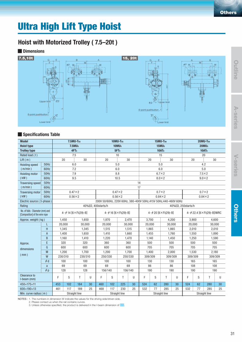
Dimensions
7.5,10t 15, 20t
Others
Ultra High Lift Type Hoist
A-series
Outline
V-seriesO
thers
Hoist with Motorized Trolley ( 7.5–20t )
NOTES : 1. The numbers in dimension W indicate the values for the driving side/driven side. 2. Please contact us when the rail contains curves. 3. Unless otherwise specified, the product is delivered in the I-beam dimension of .
Specifications Table
Trolley type
E
Rated load ( t )
20,000
7.5
Approx.
dimensions
( mm )
1,400
1,160
1,200
230/310
30,000
1,345 1,345
1,650
1,410
1,700
230/310
L
A
H
B
Lift ( m )
Hoisting speed
( m/min )
Hoisting motor
( kW )
Traversing speed
( m/min )
Traversing motor
( kW )
6.0
7.2
7.9
9.5
14
17
0.47×2
0.56×2
Electric source ( 3-phase ) 200V 50/60Hz, 220V 60Hz, 380-400V 50Hz,415V 50Hz,440-460V 60Hz
Rating 40%ED, 400starts/h 40%ED, 250starts/h
No. of falls - Diameter (mm) and [Composition] of the wire rope
Approx. weight ( kg )
100 100
69 69
128 128
G
M
W
50Hz
50Hz
50Hz
60Hz
60Hz
60Hz
60Hz
50Hz
a
Clearance to I-beam (mm)
450×175×11
600×190×13
Min. curve radius ( m )
Hoist type
Model 7.5MU-T55
7.5MU5
4FT5
320
600
320
600
1,450 1,650
20,000
1,410
1,220
1,200
250/330
30,000
1,515 1,515
1,660
1,470
1,700
250/330
100 100
69 69
156/140 156/140
360
600
360
600
1,870 2,470
20 30
F
453
461
S
102
117
T
184
189
U
30
25
Straight line
d
p
14 [6×Fi(29)-B]4-
10
5.0
6.0
8.8
10.5
0.47×2
0.56×2
10MU-T55
10MU5
5FT5
20 30
20,000
1,455
1,140
1,400
309/309
30,000
1,865 1,865
1,760
1,450
2,000
309/309
130 130
86 86
190 190
500
705
500
705
3,700 4,200
15
5.0
6.0
6.7×2
8.0×2
20 30
20,000
1,550
1,250
1,530
309/309
30,000
2,010 2,010
1,890
1,590
2,180
309/309
165 165
108 108
190 190
500
705
500
705
3,900 4,600
20
4.2
5.0
7.5×2
9.0×2
20 30
F
460
468
S
102
117
T
225
230
U
30
25
Straight line
16 [6×Fi(29)-B]4-
0.7×2
0.84×2
15MU-T56
15MU5
10AT6
F
524
532
S
62
77
T
280
285
U
30
25
Straight line
20 [6×Fi(29)-B]4-
0.7×2
0.84×2
20MU-T56
20MU5
10AT6
F
524
532
S
62
77
T
280
285
U
30
25
Straight line
22.4 [6×Fi(29)-B]IWRC4-
31
B A
W WMF
G
S
EH
+5% 0
L
TU
a
d
P
8-point pushbutton
Lower limit
Upper limitUpper limitUpper limit
BA
W WMF
G
S
E
H+
5% 0L
TU
a
d
P
8-point pushbutton
Lower limit
Upper limitUpper limitUpper limit
B
R
A
W
Q
F EH
+5% 0
L
G
K
a
d
N
M
Lower limit
6-point pushbutton (2, 3 t)8-point pushbutton (5 t)
38 (square bar or 12kg rail)
49 (Wheel width)
ℓ
Upper limitUpper limitUpper limit
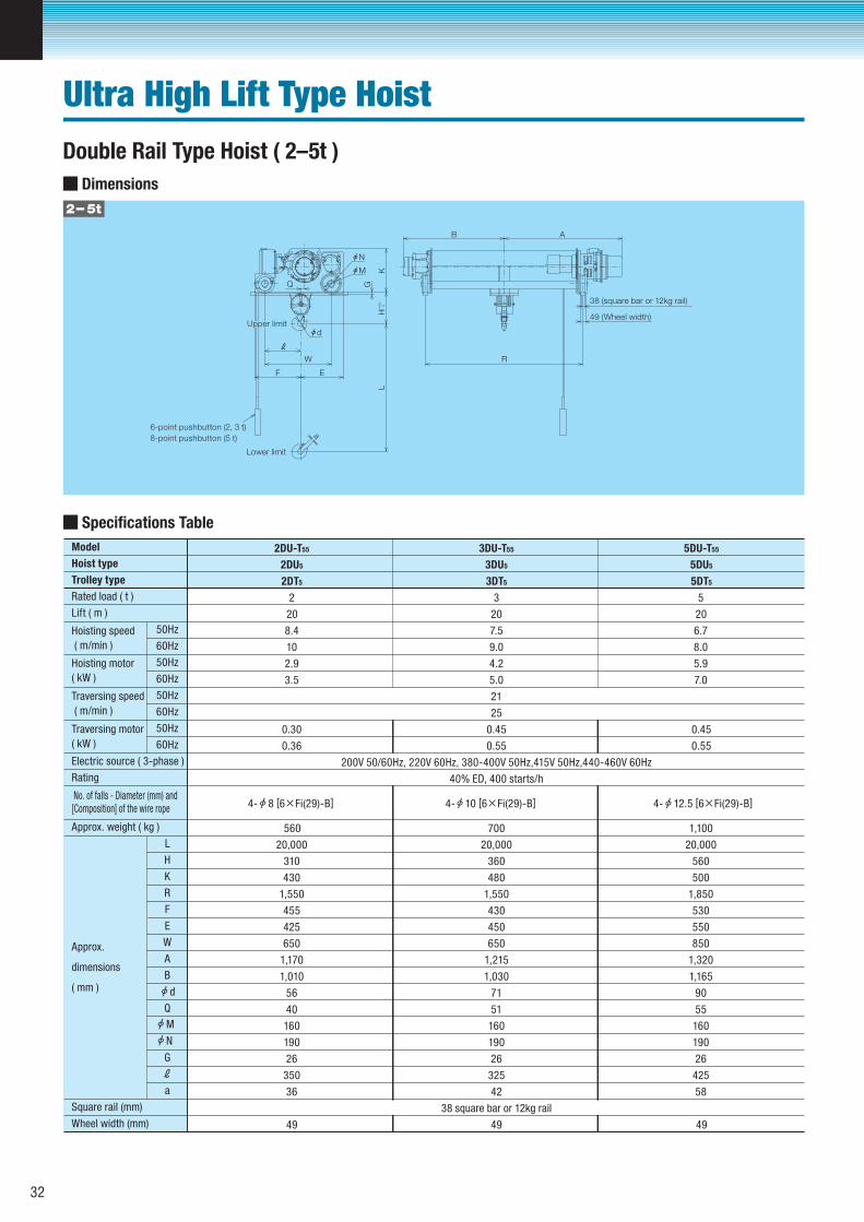
Dimensions
2– 5t
Ultra High Lift Type HoistDouble Rail Type Hoist ( 2–5t )
Specifications Table
Trolley type
F
Rated load ( t )
Approx.
dimensions
( mm )
L
K
H
R
Lift ( m )
Hoisting speed
( m/min )
Hoisting motor
( kW )
Traversing speed
( m/min )
Traversing motor
( kW )
Electric source ( 3-phase )
Rating
No. of falls - Diameter (mm) and [Composition] of the wire rope
Approx. weight ( kg )
E
W
A
B
50Hz
50Hz
50Hz
60Hz
60Hz
60Hz
60Hz
50Hz
Q
G
ℓa
Square rail (mm)
Wheel width (mm)
Hoist type
Model
d
M
N
20,000
2
430
1,550
650
1,170
310
8.4
10
2.9
3.5
0.30
0.36
1,010
56
40
2DU-T55
2DU5
2DT5
455
425
560
20
49
8 [6×Fi(29)-B]4-
160
190
26
350
36
21
25
200V 50/60Hz, 220V 60Hz, 380-400V 50Hz,415V 50Hz,440-460V 60Hz
40% ED, 400 starts/h
20,000
480
1,550
650
1,215
360
1,030
71
51
430
450
700
3
7.5
9.0
4.2
5.0
20
160
190
26
325
42
0.45
0.55
3DU-T55
3DU5
3DT5
38 square bar or 12kg rail
49
10 [6×Fi(29)-B]4-
20,000
500
1,850
850
1,320
560
1,165
90
55
160
190
26
425
58
530
550
1,100
5
6.7
8.0
5.9
7.0
20
0.45
0.55
5DU-T55
5DU5
5DT5
49
12.5 [6×Fi(29)-B]4-
32
B A
RW
Q
F E
H+
5% 0L
GK
a
d
N
M
Lower limit
ℓ
8-point pushbutton
44 (square bar or 15kg rail)53 (Wheel width)
Upper limitUpper limitUpper limit
BA
RW
Q
F E
H+
5% 0L
GK
ad
NM
Lower limit
ℓ
8-point pushbutton
55 (square bar or 22kg rail)66 (Wheel width)
Upper limitUpper limitUpper limit
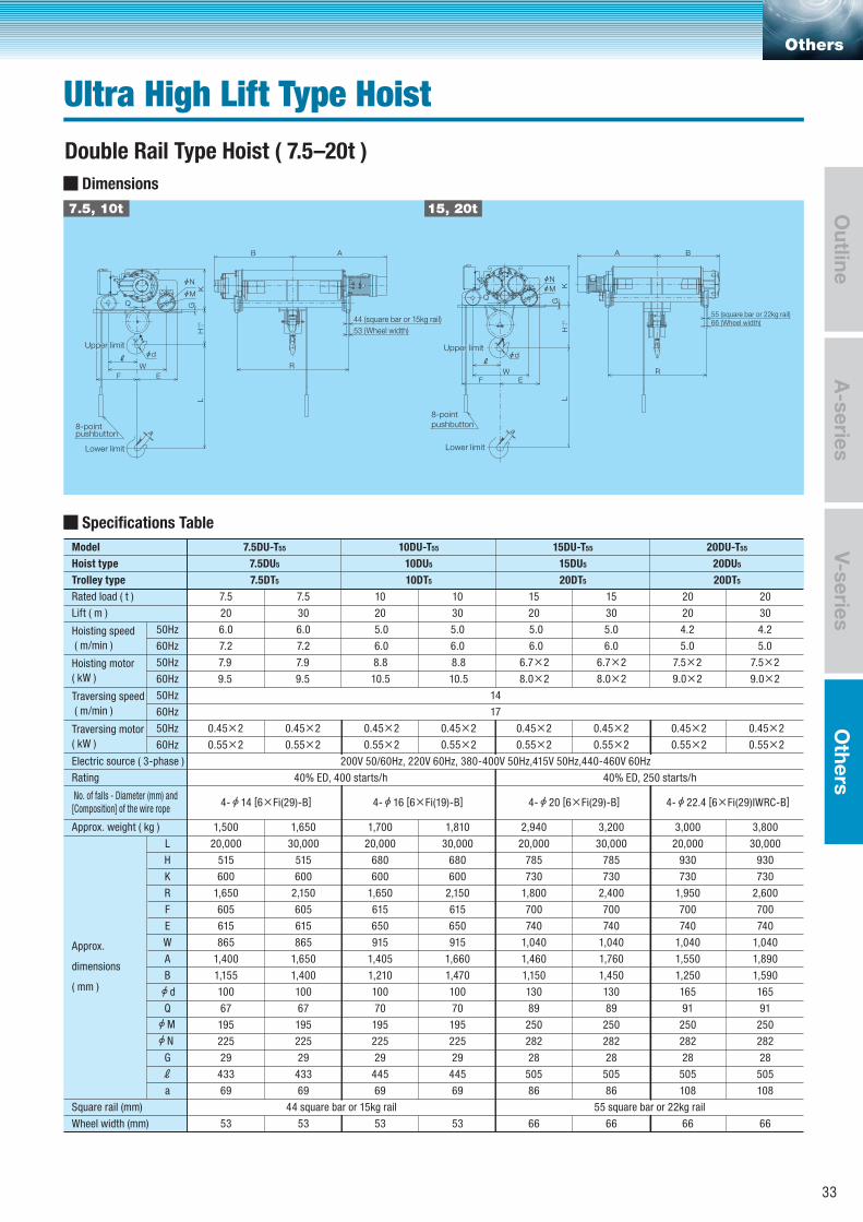
Dimensions
7.5, 10t 15, 20t
Others
Ultra High Lift Type HoistDouble Rail Type Hoist ( 7.5–20t )
A-series
Outline
V-seriesO
thers
Specifications Table
Trolley type
F
Rated load ( t )
20,000
Approx.
dimensions
( mm )
600
1,650
865
1,400
30,000
515 515
600
2,150
865
1,650
L
K
H
R
Lift ( m )
Hoisting speed
( m/min )
Hoisting motor
( kW )
Traversing speed
( m/min )
Traversing motor
( kW )
6.0
7.2
7.9
9.5
7.9
9.5
14
17
0.45×2
0.55×2
0.45×2
0.55×2
Electric source ( 3-phase ) 200V 50/60Hz, 220V 60Hz, 380-400V 50Hz,415V 50Hz,440-460V 60Hz
Rating 40% ED, 400 starts/h 40% ED, 250 starts/h
No. of falls - Diameter (mm) and [Composition] of the wire rope
Approx. weight ( kg )
1,155 1,400
100 100
67 67
E
W
A
B
50Hz
50Hz
50Hz
60Hz
60Hz
60Hz
60Hz
50Hz
Q
G
ℓa
Square rail (mm)
Wheel width (mm)
Hoist type
Model 7.5DU-T55
7.5DU5
7.5DT5
605
615
605
615
1,500 1,650
20,000
600
1,650
915
1,405
30,000
680 680
600
2,150
915
1,660
1,210 1,470
100 100
70 70
615
650
615
650
1,700 1,810
20 30
d
N
M
14 [6×Fi(29)-B]4-
5.0
6.0
8.8
10.5
8.8
10.5
0.55×2
0.45×20.45×2
0.55×2
10DU-T55
10DU5
10DT5
20 30
20,000
730
1,800
1,040
1,460
30,000
785 785
730
2,400
1,040
1,760
1,150 1,450
130 130
89 89
700
740
700
740
2,940 3,200
5.0
6.0
6.7×2
8.0×2
6.7×2
8.0×2
20 30
20,000
730
1,950
1,040
1,550
30,000
930 930
730
2,600
1,040
1,890
1,250 1,590
165 165
91 91
195 195 195 195 250 250 250 250
225 225 225 225 282 282 282 282
29 29 29 29 28 28 28 28
433 433 445 445 505 505 505 505
69 69 69 69 86 86 108 108
53 53 53 53 66 66 66 66
700
740
700
740
3,000 3,800
4.2
5.0
7.5×2
9.0×2
4.2
5.0
7.5×2
9.0×2
20 30
7.5 7.5
7.2
6.0
10 10
6.0
5.0
15 15
6.0
5.0
20 20
16 [6×Fi(19)-B]4-
0.45×2
0.55×2
0.45×2
0.55×2
0.45×2
0.55×2
0.45×2
0.55×2
15DU-T55
15DU5
20DT5
20 [6×Fi(29)-B]4-
20DU-T55
20DU5
20DT5
22.4 [6×Fi(29)IWRC-B]4-
44 square bar or 15kg rail 55 square bar or 22kg rail
33
Dimensions
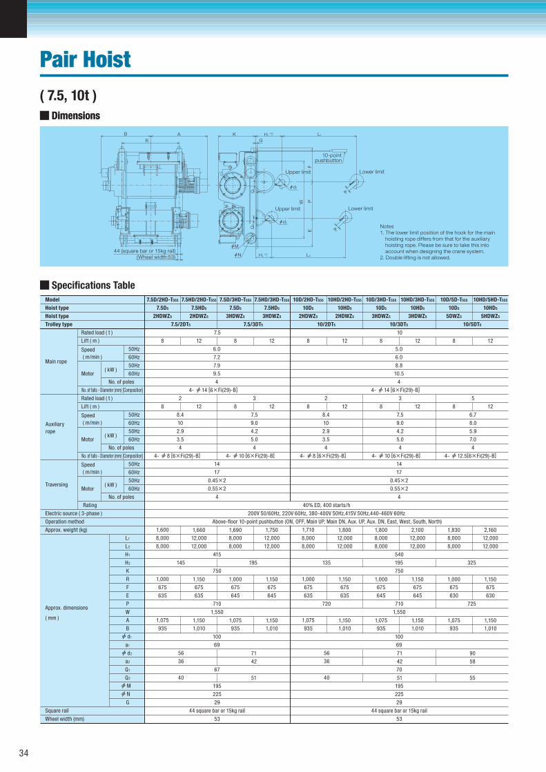
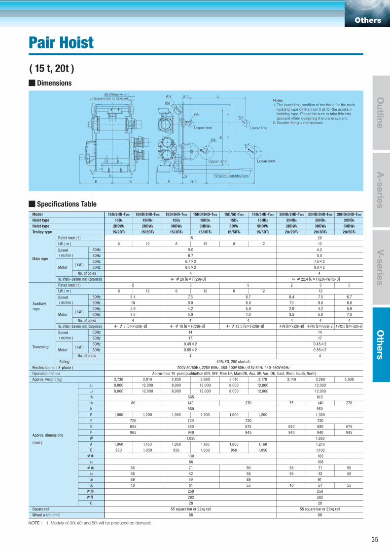
Notes1. The lower limit position of the hook for the main
hoisting rope differs from that for the auxiliary hoisting rope. Please be sure to take this into account when designing the crane system.
2. Double lifting is not allowed.
B AR
W
FE
P
H2 +30
0
H1 +5%
0 L1
L2
GK
a2
a1
d2
d1
N
M
Lower limit
Lower limit
10-pointpushbutton
Q2
Q1
(Wheel width:53)44 (square bar or 15kg rail)
Upper limitUpper limitUpper limit
Upper limitUpper limitUpper limit
Pair Hoist
Dimensions
( 7.5, 10t )
Specifications Table
Hoist type
Rated load ( t )
Lift ( m )
Speed
( m/min )Main rope
Motor ( kW )
Auxiliary
rope
8
6.0
7.2
7.9
9.5
4
Electric source ( 3-phase )
50Hz
50Hz
60Hz
60Hz
No. of poles
No. of falls - Diameter (mm) [Composition]
Hoist type
Model 7.5D/2HD-T555
7.5D5
2HDWZ5
Trolley type 7.5/2DT5 7.5/3DT5 10/2DT5 10/3DT5 10/5DT5
7.5 10
7.5HD/2HD-T555
7.5HD5
2HDWZ5
7.5D/3HD-T555
7.5D5
3HDWZ5
7.5HD/3HD-T555
7.5HD5
3HDWZ5
10D/2HD-T555
10D5
2HDWZ5
10HD/2HD-T555
10HD5
2HDWZ5
10D/3HD-T555
10D5
3HDWZ5
10HD/3HD-T555
10HD5
3HDWZ5
10D/5D-T555
10D5
5DWZ5
10HD/5HD-T555
10HD5
5HDWZ5
12 8 12
8 12 8 12
1,660 1,690 1,750
8 12 8 12 8 12
Rated load ( t )
Lift ( m )
Speed
( m/min )
Motor ( kW )
50Hz
50Hz
60Hz
60Hz
No. of poles
No. of falls - Diameter (mm) [Composition]
2 3
8.4 7.5
10 9.0
2.9 4.2
3.5 5.0
4 4
Speed
( m/min )
TraversingMotor
( kW )
14
17
0.45×2
0.55×2
4
40% ED, 400 starts/h
200V 50/60Hz, 220V 60Hz, 380-400V 50Hz,415V 50Hz,440-460V 60Hz
Above-floor 10-point pushbutton (ON, OFF, Main UP, Main DN, Aux. UP, Aux. DN, East, West, South, North)Operation method
Approx. weight (kg)
50Hz
50Hz
60Hz
60Hz
No. of poles
Rating
K
1,600
Approx. dimensions
( mm )
8,000
415
750
8,000
12,000
12,000
8,000
8,000
12,000
12,000
1,150 1,000 1,1501,000
635
675
635
675
645
675
645
675
1,150 1,075 1,1501,075
7156
4236
5140
935 1,010 935 1,010
L1
H1
L2
H2
710
1,550
R
F
E
P
W
A
B
a1
a2
Q1
Q2
G
Square rail
Wheel width (mm)
145 195
67
195
225
29
44 square bar or 15kg rail
53
d2
d1
M
N
100
69
14 [6×Fi(29)-B]4-
8 [6×Fi(29)-B]4- 10 [6×Fi(29)-B]4-
5.0
6.0
8.8
10.5
4
8 12 8 12
1,800 1,800 2,100
2 3
8.4 7.5
10 9.0
2.9 4.2
3.5 5.0
4 4
14
17
0.45×2
0.55×2
4
1,710
8,000
540
750
8,000
12,000
12,000
8,000
8,000
12,000
12,000
1,830 2,160
8,000
8,000
12,000
12,000
1,150 1,000 1,1501,000
635
675
635
675
645
675
645
675
1,000 1,150
630
675
630
675
1,150 1,075 1,1501,075
7156
42
90
5836
51 5540
935 1,010 935 1,010
1,075 1,150
935 1,010
710
1,550
135 195 325
720 725
70
195
225
29
44 square bar or 15kg rail
53
100
69
14 [6×Fi(29)-B]4-
8 [6×Fi(29)-B]4- 10 [6×Fi(29)-B]4-
8 12
5
6.7
8.0
5.9
7.0
4
12.5[6×Fi(29)-B]4-
34
Dimensions
Notes1. The lower limit position of the hook for the main
hoisting rope differs from that for the auxiliary hoisting rope. Please be sure to take this into account when designing the crane system.
2. Double lifting is not allowed.
B A
R
W
FE
P
H2 +30
0
H1 +5%
0 L1
L2
G
K
a2
a1
d2
d1
N
M
66 (Wheel width)55 (square bar or 22kg rail)
Upper limitUpper limitUpper limit
Upper limitUpper limitUpper limit
Lower limit
Lower limit
10-point pushbuttonQ
2Q
1
Others
Pair Hoist ( 15 t, 20t )
A-series
Outline
V-seriesO
thers
Specifications Table
Hoist type
Rated load ( t )
Lift ( m )
Speed
( m/min )Main rope
Motor ( kW )
Auxiliary
rope
8
5.0
6.7
6.7×2
8.0×2
4
Electric source ( 3-phase )
50Hz
50Hz
60Hz
60Hz
No. of poles
No. of falls - Diameter (mm) [Composition]
Hoist type
Model 15D/2HD-T555
15D5
2HDW5
15/2DT5
15HD/2HD-T555
15HD5
2HDW5
15/2DT5
15D/3HD-T555
15D5
3HDW5
15/3DT5
15HD/3HD-T555
15HD5
3HDW5
15/3DT5
15D/5D-T555
15D5
5DW5
15/5DT5
15D/5HD-T555
15HD5
5HDW5
15/5DT5
20HD/2HD-T555
20HD5
2HDW5
20/2DT5
20HD/3HD-T555
20HD5
3HDW5
20/3DT5
20HD/5HD-T555
20HD5
5HDW5
20/50T5Trolley type
15 20
1212 8 12 8 12
8 12 8 12 8 12
2 3
12
5Rated load ( t )
Lift ( m )
Speed
( m/min )
Motor ( kW )
50Hz
50Hz
60Hz
60Hz
No. of poles
No. of falls - Diameter (mm) [Composition]
2 3
8.4 7.5
10 9.0
2.9 4.2
3.5 5.0
4 4
Speed
( m/min )
TraversingMotor
( kW )
14
17
0.45×2
0.55×2
4
40% ED, 250 starts/h
200V 50/60Hz, 220V 60Hz, 380-400V 50Hz,415V 50Hz,440-460V 60Hz
Above-floor 10-point pushbutton (ON, OFF, Main UP, Main DN, Aux. UP, Aux. DN, East, West, South, North)Operation method
Approx. weight (kg)
50Hz
50Hz
60Hz
60Hz
No. of poles
Rating
K
2,730
Approx. dimensions
( mm )
8,000
665
850
8,000
1,000
655
720
1,060
7156
4236
5140
950
2,810
12,000
12,000
1,200
1,160
1,050
2,830
8,000
8,000
1,000
680
720
1,060
950
2,930
12,000
12,000
1,200
1,160
1,050
3,010
8,000
8,000
1,000
675
965 945
720
1,060
950
3,170
12,000
12,000
1,200
1,160
1,050
3,140
620
3,260
12,000
12,000
1,300
680
720
1,210
1,100
3,500
675
940 945
L1
H1
L2
H2
940
1,820
R
F
E
P
W
A
B
a1
a2
Q1
Q2
G
Square rail
Wheel width (mm)
80 140
89
250
282
28
55 square bar or 22kg rail
66
d2
d1
M
N
130
86
20 [6×Fi(29)-B]4-
8 [6×Fi(29)-B]4- 10 [6×Fi(29)-B]4-
4.2
5.0
7.5×2
9.0×2
4
5
6.7 8.4
8.0 10
5.9 2.9
7.0 3.5
4 4
7.5
9.0
4.2
5.0
4
6.7
8.0
5.9
7.0
4
14
17
0.45×2
0.55×2
4
810
850
75 140 270
90
58
89 89
55
940
56 71 90
40 51 55
36 5842
1,820
270
91
250
282
28
55 square bar or 22kg rail
66
165
108
22.4 [6×Fi(29)-IWRC-B]4-
12.5 [6×Fi(29)-B]4- 8 [6×Fi(29)-B]4- 10 [6×Fi(29)-B]4- 12.5 [6×Fi(29)-B]4-
NOTE : 1. Models of 30t,40t and 50t will be produced on demand.
35
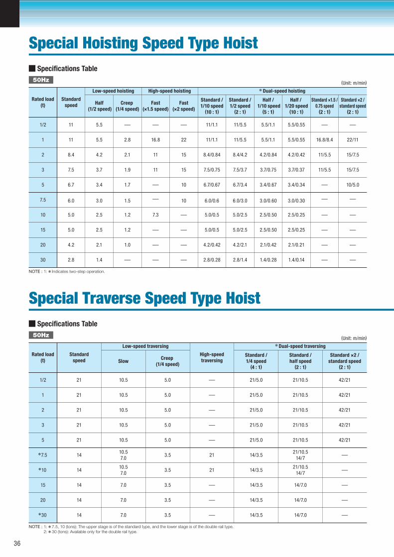
Specifications Table
1/2
1
2
3
5
7.5
10
15
20
30
11
11
8.4
7.5
6.7
6.0
5.0
5.0
4.2
2.8
5.5
5.5
4.2
3.7
3.4
3.0
2.5
2.5
2.1
1.4
– – –
2.8
2.1
1.9
1.7
1.5
1.2
1.2
1.0
–
16.8
11
11
–
–
7.3
–
–
–
–
–
–
–
22
15
15
10
10
11/1.1
11/1.1
8.4/0.84
7.5/0.75
6.7/0.67
6.0/0.6
5.0/0.5
5.0/0.5
4.2/0.42
2.8/0.28
11/5.5
11/5.5
8.4/4.2
7.5/3.7
6.7/3.4
6.0/3.0
5.0/2.5
5.0/2.5
4.2/2.1
2.8/1.4
3.7/0.75
3.4/0.67
3.0/0.60
2.5/0.50
2.5/0.50
2.1/0.42
1.4/0.28
3.7/0.37
3.4/0.34
3.0/0.30
2.5/0.25
2.5/0.25
2.1/0.21
1.4/0.14
11/5.5
–
–
–
–
–
–
–
–
–
–
–
15/7.5
4.2/0.84 4.2/0.42 11/5.5 15/7.5
5.5/1.1 5.5/0.55 16.8/8.4 22/11
5.5/1.1 5.5/0.55 – –
10/5.0
(Unit: m/min)
Rated load(t)
Standardspeed Half
(1/2 speed)Creep
(1/4 speed)Fast
(×1.5 speed)Fast
(×2 speed)
Standard /1/10 speed
(10 : 1)
Standard /1/2 speed
(2 : 1)
Half / 1/10 speed
(5 : 1)
Half / 1/20 speed
(10 : 1)
Standard ×1.5 /0.75 speed
(2 : 1)
Standard ×2 /standard speed
(2 : 1)
High-speed hoistingLow-speed hoisting
50Hz
Dual-speed hoisting
NOTE : 1: Indicates two-step operation.
Specifications Table
1/2
1
2
3
5
21 10.5 5.0
21
21
21/5.0 21/10.5 42/21
21 10.5 5.0 21/5.0 21/10.5 42/21
21 10.5 5.0 21/5.0 21/10.5 42/21
21 10.5 5.0 21/5.0 21/10.5 42/21
21 10.5 5.0 21/5.0 21/10.5
1410.57.0
3.5 14/3.521/10.5
14/7
1410.57.0
3.5 14/3.521/10.5
14/7
14 7.0 3.5 14/3.5 14/7.0
14 7.0 3.5 14/3.5 14/7.0
14 7.0 3.5 14/3.5 14/7.0
42/21
–
–
–
–
–
–
–
–
–
–
–
–
–
(Unit: m/min)
Rated load(t)
Standardspeed
High-speedtraversingSlow
Creep (1/4 speed)
Standard /1/4 speed
(4 : 1)
Standard /half speed
(2 : 1)
Standard ×2 /standard speed
(2 : 1)
Low-speed traversing
50Hz
Dual-speed traversing
NOTE : 1: 7.5, 10 (tons): The upper stage is of the standard type, and the lower stage is of the double rail type. 2: 30 (tons): Available only for the double rail type.
7.5
10
15
20
30
Special Hoisting Speed Type Hoist
Special Traverse Speed Type Hoist
36
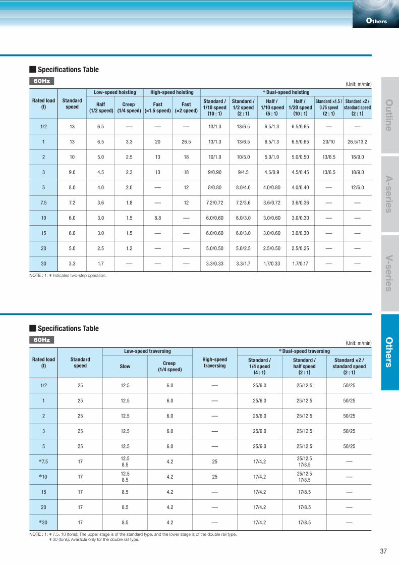
Specifications Table
1/2
1
2
3
5
7.5
10
15
20
30
13 6.5 – –
–
–
–
–
––
–
–
–
–
–
–
–
–
–
–
––
–
–
–
– – –13/1.3 13/6.5 6.5/1.3 6.5/0.65
13 6.5 3.3 20 26.5 13/1.3 13/6.5 6.5/1.3 6.5/0.65 20/10 26.5/13.2
10 5.0 2.5 13 18 10/1.0 10/5.0 5.0/1.0 5.0/0.50 13/6.5 18/9.0
9.0 4.5 2.3 13 18 9/0.90 9/4.5 4.5/0.9 4.5/0.45 13/6.5 18/9.0
8.0 4.0 2.0 12 8/0.80 8.0/4.0 4.0/0.80 4.0/0.40 12/6.0
7.2 3.6 1.8 12 7.2/0.72 7.2/3.6 3.6/0.72 3.6/0.36
6.0 3.0 1.5 8.8 6.0/0.60 6.0/3.0 3.0/0.60 3.0/0.30
6.0 3.0 1.5 6.0/0.60 6.0/3.0 3.0/0.60 3.0/0.30
5.0 2.5 1.2 5.0/0.50 5.0/2.5 2.5/0.50 2.5/0.25
3.3 1.7 3.3/0.33 3.3/1.7 1.7/0.33 1.7/0.17
(Unit: m/min)
High-speed hoistingLow-speed hoisting
60Hz
Dual-speed hoisting
NOTE : 1: Indicates two-step operation.
Specifications Table
1/2
1
2
3
5
25 12.5 6.0
25
25
25/6.0 25/12.5 50/25
25 12.5 6.0 25/6.0 25/12.5 50/25
25 12.5 6.0 25/6.0 25/12.5 50/25
25 12.5 6.0 25/6.0 25/12.5 50/25
25 12.5 6.0 25/6.0 25/12.5
1712.58.5
4.2 17/4.225/12.517/8.5
1712.58.5
4.2 17/4.225/12.517/8.5
17 8.5 4.2 17/4.2 17/8.5
17 8.5 4.2 17/4.2 17/8.5
17 8.5 4.2 17/4.2 17/8.5
50/25
–
–
–
–
–
–
–
–
–
–
–
–
–
(Unit: m/min)
Low-speed traversing
60Hz
Dual-speed traversing
NOTE : 1: 7.5, 10 (tons): The upper stage is of the standard type, and the lower stage is of the double rail type. 30 (tons): Available only for the double rail type.
Rated load(t)
Standardspeed Half
(1/2 speed)Creep
(1/4 speed)Fast
(×1.5 speed)Fast
(×2 speed)
Standard /1/10 speed
(10 : 1)
Standard /1/2 speed
(2 : 1)
Rated load(t)
Standardspeed
High-speedtraversingSlow
Creep (1/4 speed)
Standard /1/4 speed
(4 : 1)
7.5
10
30
15
20
Half / 1/10 speed
(5 : 1)
Half / 1/20 speed
(10 : 1)
Standard ×1.5 /0.75 speed
(2 : 1)
Standard ×2 /standard speed
(2 : 1)
Standard /half speed
(2 : 1)
Standard ×2 /standard speed
(2 : 1)
Others
A-series
Outline
V-seriesO
thers
37
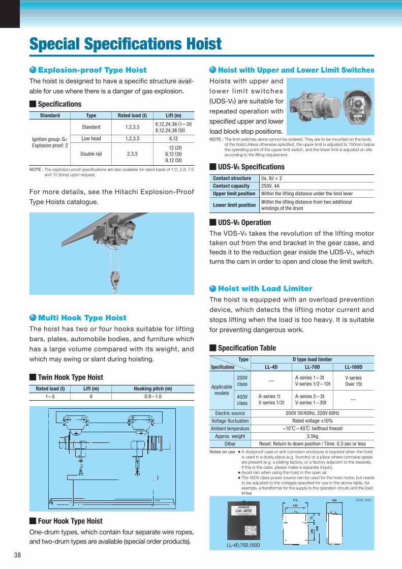
NOTE : The explosion-proof specifications are also available for rated loads of 1/2, 2.8, 7.5and 10 (tons) upon request.
Specifications
Double rail
Low head
Standard
Ignition group: G4
Explosion proof: 2
2,3,5
1,2,3,5
1,2,3,5
6,12
12 (2t)
6,12 (3t)
8,12 (5t)
6,12,24,36 (1-3t)
8,12,24,36 (5t)
Standard Lift (m)Rated load (t)Type
Twin Hook Type Hoist
61-5 0.8-1.0
Rated load (t) Hooking pitch (m)Lift (m)
NOTE : The limit switches alone cannot be ordered. They are to be mounted on the bodyof the hoist.Unless otherwise specified, the upper limit is adjusted to 150mm belowthe operating point of the upper limit switch, and the lower limit is adjusted on site according to the lifting requirement.
Notes on use A dustproof case or anti-corrosion enclosure is required when the hoist is used in a dusty place (e.g. foundry) or a place where corrosive gases are present (e.g. a plating factory, or a factory adjacent to the seaside).If this is the case, please make a separate inquiry.Avoid rain when using the hoist in the open air.The 400V class power source can be used for the hoist motor, but needsto be adjusted to the voltages specified for use in the above table, for example, a transformer for the supply to the operation circuits and the loadlimiter.
UDS-V5 Specifications
(Ia, Ib) × 2Contact structure
250V, 4AContact capacity
Within the lifting distance under the limit leverUpper limit position
Within the lifting distance from two additionalwindings of the drum
Lower limit position
Specification Table
Applicablemodels
200Vclass
400Vclass
Voltage fluctuation
Ambient temperature
Approx. weight
Other
Electric source
A-series 1-3tV-series 1/2-10t
A-series 2-3tV-series 1-30t
A-series 1tV-series 1/2t
200V 50/60Hz, 220V 60Hz
Rated voltage ±10%
-10℃-40℃ (without freeze)
3.5kg
Reset: Return to down position / Time: 0.3 sec or less
V-seriesOver 15t
—
—
LL-100DLL-70DLL-4DSpecifications
D type load limiterType
LL-4D,70D,100D
Unit: mm
Explosion-proof Type Hoist
One-drum types, which contain four separate wire ropes, and two-drum types are available (special order products).
Four Hook Type Hoist
The hoist is designed to have a specific structure avail-
able for use where there is a danger of gas explosion.
For more details, see the Hitachi Explosion-Proof
Type Hoists catalogue.
Multi Hook Type HoistThe hoist has two or four hooks suitable for lifting
bars, plates, automobile bodies, and furniture which
has a large volume compared with its weight, and
which may swing or slant during hoisting.
Hoist with Upper and Lower Limit SwitchesHoists with upper and
lower l imi t swi tches (UDS-V5) are suitable for
repeated operation with
specified upper and lower
load block stop positions.
Hoist with Load LimiterThe hoist is equipped with an overload prevention
device, which detects the lifting motor current and
stops lifting when the load is too heavy. It is suitable
for preventing dangerous work.
The VDS-V5 takes the revolution of the lifting motor taken out from the end bracket in the gear case, and feeds it to the reduction gear inside the UDS-V5, which turns the cam in order to open and close the limit switch.
UDS-V5 Operation
Special Specifications Hoist
38
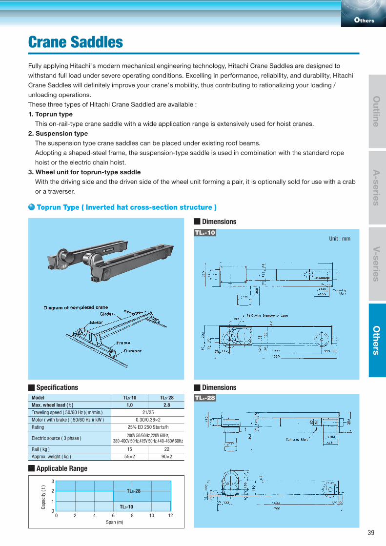
Toprun Type ( Inverted hat cross-section structure )
Others
A-series
Outline
V-seriesO
thers
Unit : mm
Model
Max. wheel load ( t )
Traveling speed ( 50/60 Hz )( m/min.)
Rating
Motor ( with brake ) ( 50/60 Hz )( kW )
Electric source ( 3 phase )
Rail ( kg )
Approx. weight ( kg )
TL5-10
1.0
15
55×2
TL5-28
2.8
21/25
0.30/0.36×2
25% ED 250 Starts/h
200V 50/60Hz,220V 60Hz,380-400V 50Hz,415V 50Hz,440-460V 60Hz
22
90×2
Dimensions
Fully applying Hitachi’s modern mechanical engineering technology, Hitachi Crane Saddles are designed to
withstand full load under severe operating conditions. Excelling in performance, reliability, and durability, Hitachi
Crane Saddles will definitely improve your crane’s mobility, thus contributing to rationalizing your loading /
unloading operations.
These three types of Hitachi Crane Saddled are available :
1. Toprun type
This on-rail-type crane saddle with a wide application range is extensively used for hoist cranes.
2. Suspension type
The suspension type crane saddles can be placed under existing roof beams.
Adopting a shaped-steel frame, the suspension-type saddle is used in combination with the standard rope
hoist or the electric chain hoist.
3. Wheel unit for toprun-type saddle
With the driving side and the driven side of the wheel unit forming a pair, it is optionally sold for use with a crab
or a traverser.
TL5-10
DimensionsSpecifications
Applicable Range
TL5-28
Span (m)
Cap
acit
y (
t )
00
1
2
3
2 4 6 8 10 12
TL5-10
TL5-28
Crane Saddles
39
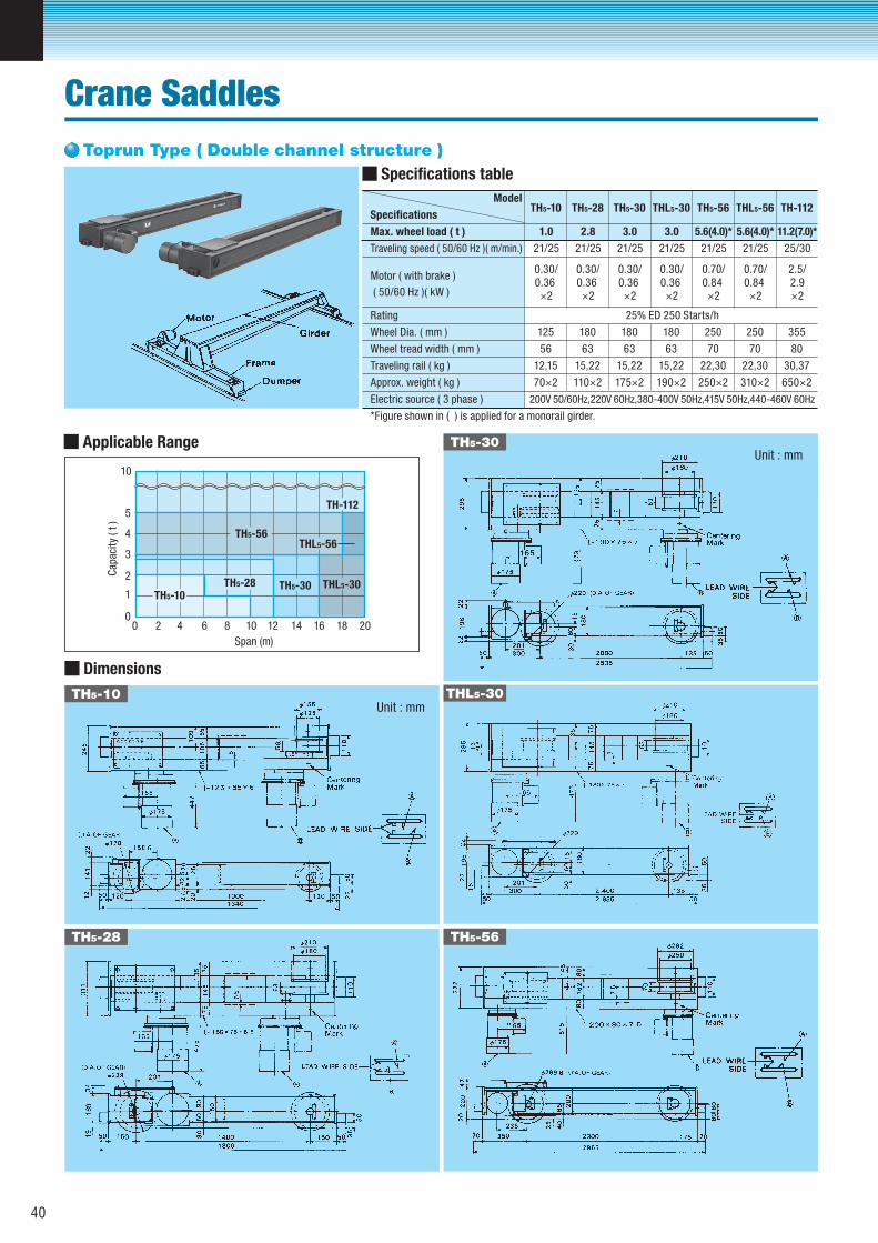
Unit : mm
Model
Specifications
Max. wheel load ( t )
Traveling speed ( 50/60 Hz )( m/min.)
Motor ( with brake )
( 50/60 Hz )( kW )
Rating
Wheel Dia. ( mm )
Wheel tread width ( mm )
Traveling rail ( kg )
Approx. weight ( kg )
Electric source ( 3 phase )
*Figure shown in ( ) is applied for a monorail girder.
TH5-10
0.30/0.36 ×2
125
56
12,15
70×2
1.0
21/25
TH5-28
0.30/0.36 ×2
180
63
15,22
110×2
2.8
21/25
TH5-30
0.30/0.36 ×2
180
63
15,22
175×2
3.0
21/25
THL5-30
0.30/0.36 ×2
180
63
15,22
190×2
200V 50/60Hz,220V 60Hz,380-400V 50Hz,415V 50Hz,440-460V 60Hz
3.0
21/25
TH5-56
0.70/0.84 ×2
250
70
22,30
250×2
5.6(4.0)*
21/25
THL5-56
0.70/0.84 ×2
250
70
22,30
310×2
5.6(4.0)*
21/25
TH-112
2.5/2.9×2
355
80
30,37
650×2
11.2(7.0)*
25/30
25% ED 250 Starts/h
Dimensions
TH5-10
TH5-30
TH5-28
THL5-30
TH5-56
Specifications table
Applicable Range
Span (m)
Cap
acit
y (
t )
0
1
0
2
3
4
5
10
2 4 6 8 10 12 14 16 18 20
TH5-28TH5-10
TH5-56
TH-112
TH5-30
THL5-56
THL5-30
Toprun Type ( Double channel structure )
Crane Saddles
40
Unit : mm
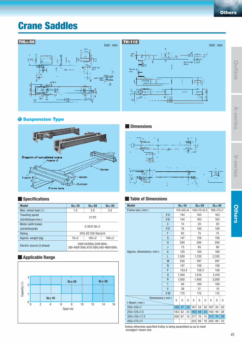
200V 50/60Hz,220V 60Hz,380-400V 50Hz,415V 50Hz,440-460V 60Hz
Suspension Type
Others
Model
Frame size ( mm )
Approx. dimensions ( mm )
C
F
G
H
J
K
L
M
N
P
Q
R
T
V
I-Beam ( mm )
Dimensions ( mm )
200×100×7
250×125×7.5
300×150×11.5
450×175×11
Unless otherwise specified trolley is being assembled so as to meet smudged I-beam size.
294
147
65
76
15
73
125
1,300
350
147
153.4
1,394
1,000
90
36
175
E
158
183
208
S
37
62
87
U
25
22
13
144
125×65×6
SL5-10
144
294
158
75
100
20
85
150
1,720
397
158
158.3
1,816
1,400
100
31
175
E
167
192
217
243
S
24
49
74
99
U
25
23
15
18
163
150×75×6.5
SL6-28
163
294
158
75
100
20
90
180
2,320
397
158
158
2,416
2,000
100
10
175
E
167
192
217
242
S
24
49
74
99
U
30
28
20
23
163
180×75×7
SL5-30
163
Model
Max. wheel load ( t )
Traveling speed
(50/60Hz)(m/min.)
Motor (with brake)
(50/60Hz)(kW)
Rating
Approx. weight (kg)
Electric source (3 phase)
70×2
1.0
SL5-10
105×2
25% ED 250 Starts/h
0.30/0.36×2
21/25
2.8
SL6-28
140×2
3.0
SL5-30
B
D
A
W
THL5-56 TH-112
Table of DimensionsSpecifications
Applicable Range
Dimensions
Span (m)
Cap
acit
y (
t )
00
1
2
3
2 4 6 8 10 12 14 16
SL5-10
SL6-28 SL5-30
Crane Saddles
Unit : mm
A-series
Outline
V-seriesO
thers
41
Unit : mm
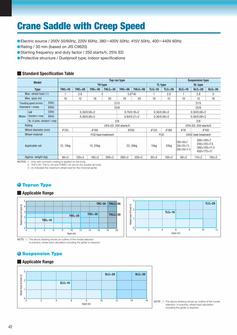
Toprun Type
Suspension Type
NOTES : 1 : Only anti-corrosion coating is applied on the body. 2 : THC5-56, THLC5-56 and THMC5-45 are for the double rail hoist. 3 : (4) indicates the maximum wheel load for the monorail girder.
NOTE : 1. The above drawing shows an outline of the model selection. In practice, wheel load calculation including the girder is required.
Standard Specification Table
Max. wheel load ( t )
Max. span (m)
Travelling speed (m/min)Standard / creep
50Hz
60Hz
50Hz
60Hz
No. of poles, standard / creep
Motor
kWStandard / creep
Rating
Wheel diameter (mm)
Wheel material
Applicable rail
Approx. weight (kg)
1
10 12 16 20
21/5
25/6
2/8
25% ED, 250 starts/h
0.30/0.08×2 0.70/0.18×2 0.30/0.08×2
0.36/0.09×2 0.84/0.21×2 0.36/0.09×2
FCD heat treatment FCD
15, 22kg12, 15kg 22, 30kg 15kg 22kg
200×280×2 260×2 320×2 65×2 100×2
18 20 10 12 10 12
21/5
25/6
0.30/0.08×2
0.36/0.09×2
2/8
25% ED, 250 starts/h
200×100×7250×125×7.5300×150×11.5450×175×11
200×100×7250×125×7.5300×150×11.5
115×2 150×280×2
S45C heat treatment
16
2.8 3 5.6 (4) 1 2.8 1 2.8 3
Type
ModelTop run type
TH type
THC5-10 THC5-28 THC5-30 THLC5-30 THC5-56 THLC5-56 TLC5-10 TLC5-28 SLC5-10 SLC5-28 SLC5-30
TL type
Suspension type
SL type
185×2120×2
125 180 250 125 180 76 100
Applicable Range
Span (m)
00
1
2
3
4
5
2 4 6 8 10 12 14 16 18 20
Rat
ed lo
ad o
f h
oist
(t)
THC5-10
THC5-28THC5-30
THC-56 THLC5-56
THLC5-30
Span (m)
00
1
2
3
2 4 6 8 10 12
Rat
ed lo
ad o
f h
oist
(t)
TLC5-10
TLC5-28
NOTE : 1. The above drawing shows an outline of the model selection. In practice, wheel load calculation including the girder is required.
Applicable Range
Span (m)
00
1
2
3
2 4 6 8 10 12 14 16
Rat
ed lo
ad o
f h
oist
(t)
SLC5-10
SLC5-28 SLC5-30
Electric source / 200V 50/60Hz, 220V 60Hz, 380-400V 50Hz, 415V 50Hz, 400-440V 60Hz Rating / 30 min (based on JIS C9620)Starting frequency and duty factor / 250 starts/h, 25% EDProtective structure / Dustproof type, indoor specifications
Crane Saddle with Creep Speed
42
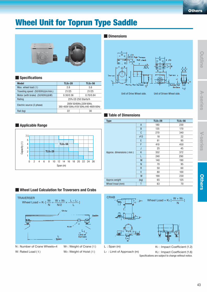
Model
Max. wheel load ( t )
Traveling speed (50/60Hz)(m/min.)
Motor (with brake) (50/60Hz)(kW)
Rating
Electric source (3 phase)
Rail (kg)
2.8
TLU5-28
200V 50/60Hz,220V 60Hz,380-400V 50Hz,415V 50Hz,440-460V 60Hz
25% ED 250 Starts/h
5.6
21/25 21/25
0.30/0.36 0.70/0.84
22 30
TLU5-56
Type
Approx.weight
Wheel tread (mm)
Approx. dimensions ( mm )
B
A
C
E
F
J
K
L
M
N
R
V
W
(kg)
T
352
25
410
81
18
240
140
70
50
80
190
65
63
135
180
TLU5-28
270
TLU5-56
372
45
450
95
22
290
190
95
60
100
230
125
70
170
230
340
D
N : Number of Crane Wheels=4
W : Rated Load ( t )
W1 : Weight of Crane ( t )
W2 : Weight of Hoist ( t )
L : Span (m)
L1 : Limit of Approach (m)
K1 : Impact Coefficient (1.2)
K2 : Impact Coefficient (1.6)Specifications are subject to change without notice.
Dimensions
Specifications
Table of Dimensions
Wheel Load Calculation for Traversers and Crabs
Unit of Drive Wheel side. Unit of Driven Wheel side.
Span (m)
Cap
acit
y (
t )
0
1
2
3
4
5
7.5
2 4 6 8 10 12 14 16 18 20 22 24 26
TLU5-28
TLU5-56
TRAVERSERW1 W + W2 L − L1
N N/2 LWheel Load = K1 [ + × ]
CRAB W + W2
NWheel Load = K2 [ ]
Others
Wheel Unit for Toprun Type Saddle
A-series
Outline
V-seriesO
thers
Applicable Range
43
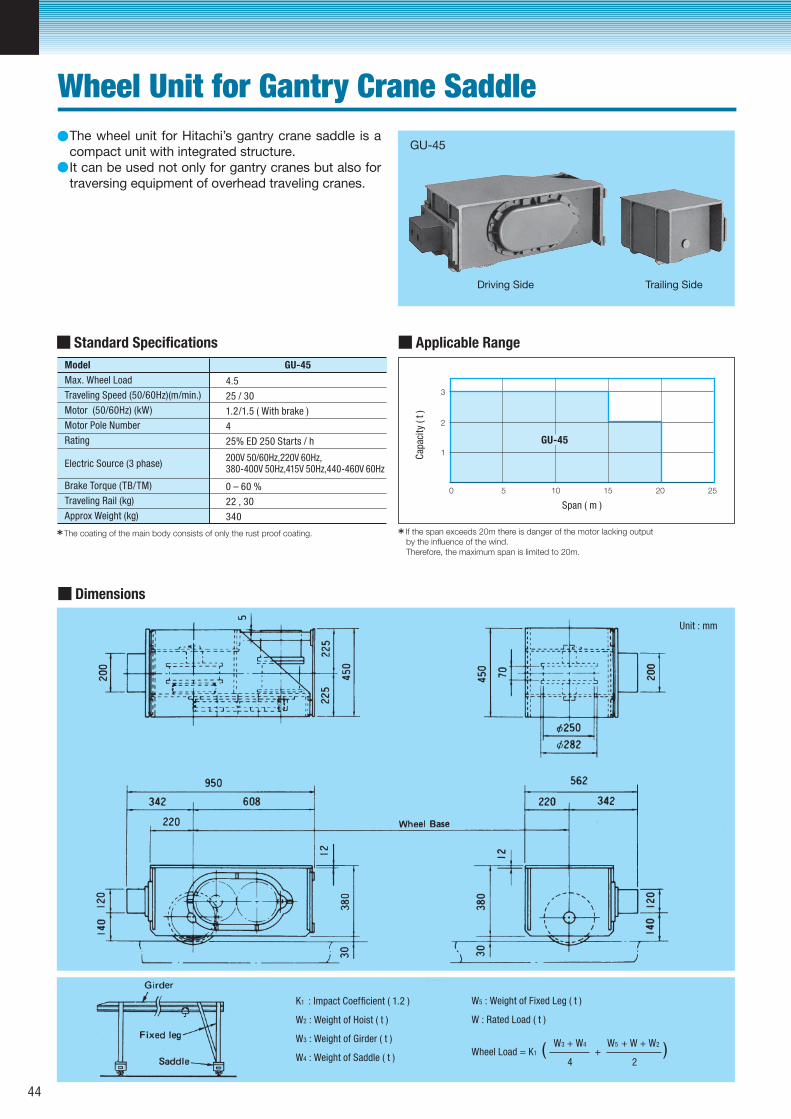
Span ( m )
Unit : mm
K1 : Impact Coefficient ( 1.2 )
W2 : Weight of Hoist ( t )
W3 : Weight of Girder ( t )
W4 : Weight of Saddle ( t )
W5 : Weight of Fixed Leg ( t )
W : Rated Load ( t )
Cap
acit
y (
t )
Dimensions
Standard Specifications Model GU-45
Max. Wheel Load
Traveling Speed (50/60Hz)(m/min.)
Motor (50/60Hz) (kW)
Motor Pole Number
Rating
Electric Source (3 phase)
Brake Torque (TB/TM)
Traveling Rail (kg)
Approx Weight (kg)
4.5
25 / 30
1.2/1.5 ( With brake )
4
25% ED 250 Starts / h
0 – 60 %
22 , 30
340
Applicable Range
The wheel unit for Hitachi’s gantry crane saddle is a compact unit with integrated structure.It can be used not only for gantry cranes but also for traversing equipment of overhead traveling cranes.
●
●
The coating of the main body consists of only the rust proof coating. If the span exceeds 20m there is danger of the motor lacking output by the influence of the wind. Therefore, the maximum span is limited to 20m.
0
1
2
3
5 10 15 20 25
GU-45
GU-45
Driving Side Trailing Side
200V 50/60Hz,220V 60Hz,380-400V 50Hz,415V 50Hz,440-460V 60Hz
W3 + W4 W5 + W + W2
4 2Wheel Load = K1 ( + )
Wheel Unit for Gantry Crane Saddle
44
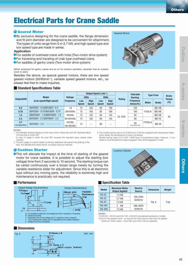
Unit : mmFig. A
tatb tc
(Output Voltage Characteristics) (Tarque Characteristics)
By exclusive designing for the crane saddle, the flange dimension and fit joint diameter are designed to be convenient for attachment.The types of units range from 0.4–3.7 kW, and high speed type and low speed type are made in series.
ApplicationFor saddle of overhead crane with hoist.(Two-motor drive system)For traversing and traveling of crab type overhead crane.For saddles of gantry crane (Two-motor drive system)
(When employed for gantry cranes and so on for outdoor operation, ascertain that an outdoor cover is used.)
Besides the above, as special geared motors, there are low speed geared motors (50/60min-1), variable speed geared motors, etc., so please feel free to make inquiries.
This will alleviate the impact at the time of starting of the geared motor for crane saddles. It is possible to adjust the starting (low voltage) time from 2 seconds to 10 second. The starting torque can be varied continuously over a broad range merely by turning the variable resistance slider for adjustment. Since this is all electronic type without any moving parts, the reliability is extremely high and maintenance is practically not required.
●
●●●
●
Specification Table
Model
HQ-0C
HQ-2C
HQ-4C
HQ-1HC
HQ-4HC
1.5 kW
3.7 kW
7.5 kW
3 kW
7.5 kW
Fig. A 3 kg
190-230V
50/60 Hz
380-460V
50/60 Hz
Standard Specifications Table
Output(kW)Model
(Low speed/High speed)
Voltage
Frequency
3
200V 50/60Hz,
220V 60Hz,
380-400V 50Hz,
415V 50Hz,
440-460V 60Hz
S3 25%
(N)YEGEH - 0.4/(N)YJGEH - 0.4
(N)YEGEH - 0.75/(N)YJGEH - 0.75
(NB)YEGEH - 1.5/(NB)YHGEH - 1.5
(N)YEGEH - 2.2/(N)YHGEH - 2.2
(N)YEGEH - 3.7/
Output Speed ( min-1 )Type From Brake
Torque
(%)BrakeMotor
60Hz50Hz
LowSpeed
HighSpeed
LowSpeed
HighSpeed
Rating
Maximum MotorOutput Applied
ElectricSource
Dimension Weight
Tolerable
Starting
Frequency
(times/hr.)
0.4
0.75
1.5
2.2
3.7( Low Speed Only )
75
75
75
75
160
160
120
120
90
90
90
90
190
190
145
145
120
100
95
90
MS-HB
MS-HB
MS-HB
MS-FE
Performance
Dimensions
MS-FE
YTOG-K
YTFOG-K90(Low-Speed Only)
40
9075
NOTES : 1. The tolerable starting frequency is the value which makes the load GD2 (flywheel effect) 10 times that of motor GD2
In case of usage in which the load GD2 exceeds the standard value, please make inquiries.
2. The joint usage of cushion starter or primary resistance will prevent the shaking of the load, and alleviate the impact shock, so always use such devices.
NOTES : (1)HQ-0C—HQ-4C and HQ-1HC—HQ-4HC are planned production models.(2)As for the applied motor , so long as the total output is less than the applied maximum motor output , more than one motor may be operated.
3. The models having output of 2.2 kW and 3.7 kW are equipped with temperature relays which detect the temperature of motor coil directly.
Models having output of 0.4 kW–1.5kW have no temperature relays. However , if you desire to have temperature relays equipped, they will be equipped to order.
ta : It is possible to adjust the low voltage time from 2 seconds to 10 seconds.tb : Closed circult time.tc : Preparation time for low voltage and 0.1 seconds or more is required.a : This is starting time voltage and it is adjustable by the variable resistance.b : Voltage at the time of operation.
Geared Motor
Cushion StarterCushion Starter
Geared Motor
Others
Electrical Parts for Crane Saddle
A-series
Outline
V-seriesO
thers
45
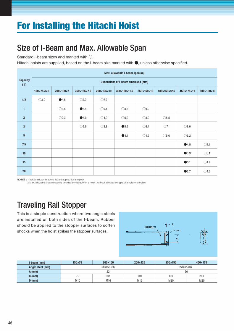
Size of I-Beam and Max. Allowable Span
Traveling Rail StopperThis is a simple construction where two angle steels
are installed on both sides of the I-beam. Rubber
should be applied to the stopper surfaces to soften
shocks when the hoist strikes the stopper surfaces.
Capacity
( t )
1/2
1
2
3
5
7.5
10
15
20
Max. allowable I-beam span (m)
Dimensions of I-beam employed (mm)
150×75×5.5
○3.0
○3.5
○2.3
○2.9
○7.0
○7.1
○7.1
○5.6
○7.9
○6.4
○6.4
○6.2
○6.1
○4.9
○4.9
○4.9
○4.3
○8.6
○8.5
○9.9
○8.0
○8.0
○6.9
○3.8
●4.5
●4.5
●3.9
●3.1
●2.7
●5.4
●5.6
●4.0
●4.1
200×100×7 250×125×7.5 250×125×10 300×150×11.5 350×150×12 400×150×12.5 450×175×11 600×190×13
I-beam (mm)
Angle steel (mm)
A (mm)
B (mm)
D (mm)
NOTES : 1.Values shown in above list are applied for a telpher. 2.Max. allowable I-beam span is decided by capacity of a hoist , without affected by type of a hoist or a trolley.
Standard I-beam sizes and marked with ○.
Hitachi hoists are supplied, based on the I-beam size marked with ●, unless otherwise specified.
150×75
50×50×6
22
70
M10 M16 M16 M20 M20
105 110 190 280
30
65×65×6
200×100 250×125 350×150 450×175
For Installing the Hitachi Hoist
46
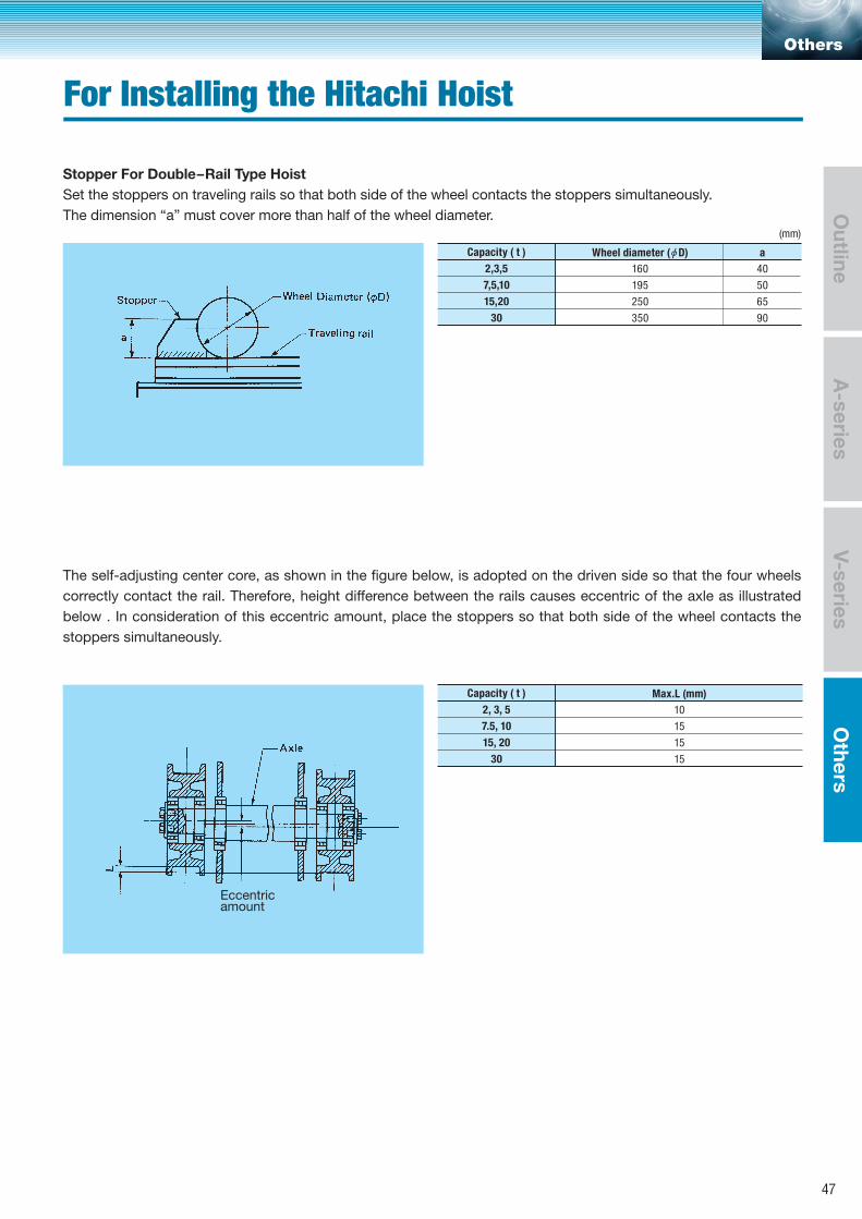
Capacity ( t )
2,3,5
7,5,10
15,20
30
Wheel diameter ( D) a
(mm)
160
195
250
350
40
50
65
90
Stopper For Double–Rail Type HoistSet the stoppers on traveling rails so that both side of the wheel contacts the stoppers simultaneously. The dimension “a” must cover more than half of the wheel diameter.
The self-adjusting center core, as shown in the figure below, is adopted on the driven side so that the four wheels correctly contact the rail. Therefore, height difference between the rails causes eccentric of the axle as illustrated below . In consideration of this eccentric amount, place the stoppers so that both side of the wheel contacts the stoppers simultaneously.
Capacity ( t )
2, 3, 5
7.5, 10
15, 20
30
Max.L (mm)
10
15
15
15
Eccentricamount
Others
For Installing the Hitachi Hoist
A-series
Outline
V-seriesO
thers
47
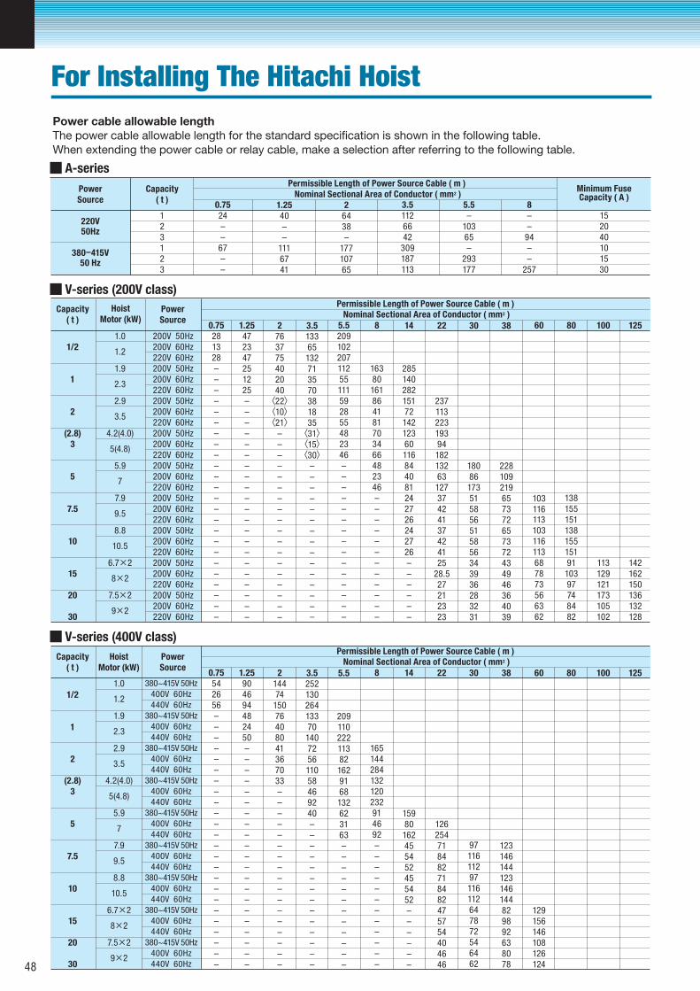
PowerSource
PowerSource
Capacity( t )
Capacity( t )
HoistMotor (kW)
220V50Hz
380–415V50 Hz
Permissible Length of Power Source Cable ( m )Minimum FuseCapacity ( A )Nominal Sectional Area of Conductor ( mm2 )
Permissible Length of Power Source Cable ( m )Nominal Sectional Area of Conductor ( mm2 )
0.7524––67––
0.75281328––––––––––––––––––––––––
1.25472347251225–––––––––––––––––––––
2763775402040〈22〉〈10〉〈21〉
––––––––––––––––––
3.513365132713570381835〈31〉〈15〉〈30〉
–––––––––––––––
5.520910220711255111592855482346–––––––––––––––
1/2
1
2
(2.8)3
5
7.5
10
15
20
30
1.0
1.9
2.9
4.2(4.0)
5.9
7.9
8.8
6.7×2
7.5×2
1.2
2.3
3.5
5(4.8)
7
9.5
10.5
8×2
9×2
200V 50Hz200V 60Hz220V 60Hz200V 50Hz200V 60Hz220V 60Hz200V 50Hz200V 60Hz220V 60Hz200V 50Hz200V 60Hz220V 60Hz200V 50Hz200V 60Hz220V 60Hz200V 50Hz200V 60Hz220V 60Hz200V 50Hz200V 60Hz220V 60Hz200V 50Hz200V 60Hz220V 60Hz200V 50Hz200V 60Hz220V 60Hz
1.2540––
1116741
26438–
17710765
3.51126642
309187113
5.5–
10365–
293177
8––
94––
257
123123
152040101530
Power cable allowable lengthThe power cable allowable length for the standard specification is shown in the following table.When extending the power cable or relay cable, make a selection after referring to the following table.
A-series
V-series (200V class)
16380161864181703466482346––––––––––––
8
2851402821517214212360116844081242726242726––––––
14
237113223193941821326312737424137424125
28.527212323
22
18086173515856515856343936283231
30
228109219657372657372434946364039
38
103116113103116113687873566362
60
1381551511381551519110397748482
80
113129121173105102
100
142162150136132128
125
PowerSource
Capacity( t )
HoistMotor (kW)
Permissible Length of Power Source Cable ( m )Nominal Sectional Area of Conductor ( mm2 )
0.75542656––––––––––––––––––––––––
1.25904694482450–––––––––––––––––––––
214474
15076408041367033–––––––––––––––––
3.525213026413370140725611058469240––––––––––––––
5.5
209110222113821629168132623163––––––––––––
1/2
1
2
(2.8)3
5
7.5
10
15
20
30
1.0
1.9
2.9
4.2(4.0)
5.9
7.9
8.8
6.7×2
7.5×2
1.2
2.3
3.5
5(4.8)
7
9.5
10.5
8×2
9×2
380~415V 50Hz
400V 60Hz
440V 60Hz
380~415V 50Hz
400V 60Hz
440V 60Hz
380~415V 50Hz
400V 60Hz
440V 60Hz
380~415V 50Hz
400V 60Hz
440V 60Hz
380~415V 50Hz
400V 60Hz
440V 60Hz
380~415V 50Hz
400V 60Hz
440V 60Hz
380~415V 50Hz
400V 60Hz
440V 60Hz
380~415V 50Hz
400V 60Hz
440V 60Hz
380~415V 50Hz
400V 60Hz
440V 60Hz
V-series (400V class)
165144284132120232914692––––––––––––
8
15980162455452455452––––––
14
126254718482718482475754404646
22
9711611297116112647872546462
30
123146144123146144829892638078
38
129156146108126124
60 80 100 125
For Installing The Hitachi Hoist
48
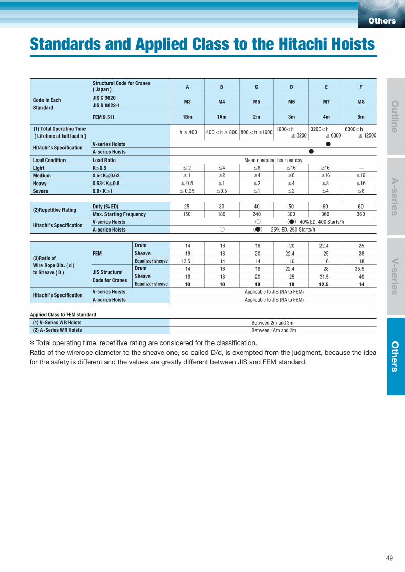
* Total operating time, repetitive rating are considered for the classification.Ratio of the wirerope diameter to the sheave one, so called D/d, is exempted from the judgment, because the idea for the safety is different and the values are greatly different between JIS and FEM standard.
Code in Each
Standard
Hitachi’ s Specification
Structural Code for Cranes( Japan ) A
M3
1Bm 1Am 2m 3m 4m 5m
M4 M5 M6 M7 M8
B C D E F
JIS C 9620
JIS B 8822-1
V-series Hoists
A-series Hoists
(1) Total Operating Time
( Lifetime at full load h )
FEM 9.511
h ≦ 400 400 < h ≦ 800 800 < h ≦16001600< h ≦ 3200
3200< h ≦ 6300
6300< h ≦ 12500
●
○ (●)○ (●)
●Load Condition
Light
Medium
Heavy
Severe
Hitachi’ s SpecificationV-series Hoists
A-series Hoists
(2)Repetitive Rating
Load Ratio
K≦0.5
0.5<K≦0.63
0.63<K≦0.8
0.8<K≦1
Duty (% ED)
Max. Starting Frequency
Mean operating hour per day
≦ 2 ≦4 ≦8 ≦16 ≧16 ̶
≦ 1 ≦2 ≦4 ≦8 ≦16 ≧16
≦ 0.5
≦ 0.25
≦1 ≦2 ≦4 ≦8 ≦16
25 30 40 50 60 60
150 180 240 300 360 360
≦0.5 ≦1 ≦2 ≦4 ≦8
40% ED, 400 Starts/h
25% ED, 250 Starts/h
Hitachi’ s Specification
Applied Class to FEM standard
V-series Hoists
A-series Hoists
(1) V-Series WR Hoists
(2) A-Series WR Hoists
Between 2m and 3m
Between 1Am and 2m
(3)Ratio of
Wire Rope Dia. ( d )
to Sheave ( D )
Drum
Sheave
Equalizer sheave
Drum
Sheave
Equalizer sheave
JIS Structural
Code for Cranes
FEM
14
16
12.5
14
16
10
16
18
14
16
18
10
18
20
14
18
20
10
20
22.4
16
22.4
25
10
22.4
25
16
28
31.5
12.5
25
28
18
35.5
40
14
Applicable to JIS (NA to FEM)
Applicable to JIS (NA to FEM)
Others
Standards and Applied Class to the Hitachi Hoists
A-series
Outline
V-seriesO
thers
49

Memo
50

Others
A-series
Outline
V-seriesO
thers
51
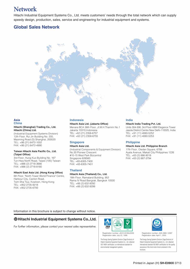
Information in this brochure is subject to change without notice.
For further information, please contact your nearest sales representative.
Printed in Japan (H) SH-E090X 0713
NetworkHitachi Industrial Equipment Systems Co., Ltd. meets customers’ needs through the total network which can supply speedy design, production, sales, service and engineering for industrial equipment and systems.
AsiaChina
Hitachi (Shanghai) Trading Co., Ltd.
Hitachi (China) Ltd.
(Industrial Equipment Systems Division)
12th Floor, Rui Jin Building No. 205,
Maoming Road (S) Shanghai, 200020
TEL: +86 (21) 6472-1002
FAX: +86 (21) 6472-4990
Taiwan Hitachi Asia Pacific Co., Ltd.
(Taipei Office)
3rd Floor, Hung Kuo Building No. 167
Tun-Hwa North Road, Taipei (105) Taiwan
TEL: +886 (2) 2718-3666
FAX: +886 (2) 2718-8180
Hitachi East Asia Ltd. (Hong Kong Office)
6th Floor, "North Tower World Finance" Centre,
Harbour City, Canton Road,
Tsim Sha Tsui, Kowloon, Hong Kong
TEL: +852 2735-9218
FAX: +852 2735-6793
Indonesia
Hitachi Asia Ltd. (Jakarta Office)
Menara BCA 38th Floor, JI.M.H.Thamrin No.1
Jakarta 10310,Indonesia
TEL: +62 (21) 2358-6757
FAX: +62 (21) 2358-6755
Singapore
Hitachi Asia Ltd.
(Industrial Components & Equipment Division)
No.30 Pioneer Crescent
#10-15 West Park Bizcentral
Singapore 628560
TEL: +65-6305-7400
FAX: +65-6305-7401
Thailand
Hitachi Asia (Thailand) Co., Ltd.
18th Floor, Ramaland Building, 952
Rama IV Road Bangrak, Bangkok 10500
TEL: +66 (2) 632-9292
FAX: +66 (2) 632-9299
India
Hitachi India Trading Pvt. Ltd.
Units 304-306, 3rd Floor ABW Elegance Tower
Jasola District Centre New Delhi-110025, India
TEL: +91 (11) 4060-5252
FAX: +91 (11) 4060-5253
Philippine
Hitachi Asia Ltd. Philippine Branch
17th Floor, Oledan Square, 6788
Ayala Avenue, Makati City Philippines 1226
TEL: +63 (2) 886-9018
FAX: +63 (2) 887-3794
Global Sales Network
The Energy Saving Systems Division (Taga Division) of
Hitachi Industrial Equipment Systems Co., Ltd. obtained
ISO 14001 certification, an international standard for
environmental management systems.
The Energy Saving Systems Division (Taga Division) of
Hitachi Industrial Equipment Systems Co., Ltd. obtained
international standard ISO 9001 certification for the quality
assurance of the hoist motor block contained in this
brochure.
Registration number: JQA-QMA 12087Registration date: April 1, 2005
Registration number: JACO-EC99J2009Registration date: July 22, 1996
EC97J1095