Multi-Axis Position Control by EtherCAT Real-time Networking
2
EtherCAT Applications Overview
The EtherCAT Control Approach
The EtherCAT Data Processing
Time Synchronization Requirements in Distributed Systems
EtherCAT Distributed Clock Mechanism
Back to EtherCAT and Motion Control
Servo Drives , DS 402 Device Profiles and CoE
Practical Real Time Control Networks Inputs / outputs synchronization Requirements
Summary
Lecture Topics
3
EtherCAT Applications Overview
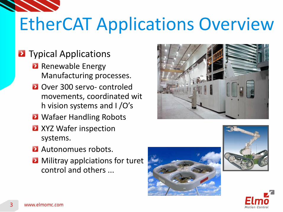
Typical ApplicationsRenewable Energy Manufacturing processes.
Over 300 servo- controled movements, coordinated with vision systems and I /O’s
Wafaer Handling Robots
XYZ Wafer inspection systems.
Autonomues robots.
Militray applciations for turet control and others ...
5
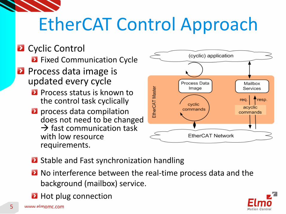
EtherCAT Control ApproachCyclic Control
Fixed Communication Cycle
Process data image is updated every cycle
Process status is known to the control task cyclicallyprocess data compilation does not need to be changed fast communication task with low resource requirements.
Stable and Fast synchronization handling
No interference between the real-time process data and the background (mailbox) service.
Hot plug connection
6
EtherCAT Control Approach
What Type of Data is Shared on the Network ?Usually, a control system needs to have, on a periodic time intervals the following:
Inputs: Latched Sensors Data such as Positions, Velocities, Currents, System Status, IO’s etc,Outputs: Control Law commands, or Trajectory Information, or Higher Drive Level Commands.
The specific nature of the data being transferred on the network depends on the operation mode of the slave drive.The terminology used for Drive Slaves operation is “Device Profile”. A common standard for Drive Device Profiles is the “DS-402”, CANOpen Device Profile, and “CoE” – Can Over EtherCAT. More on that , Later On …
7
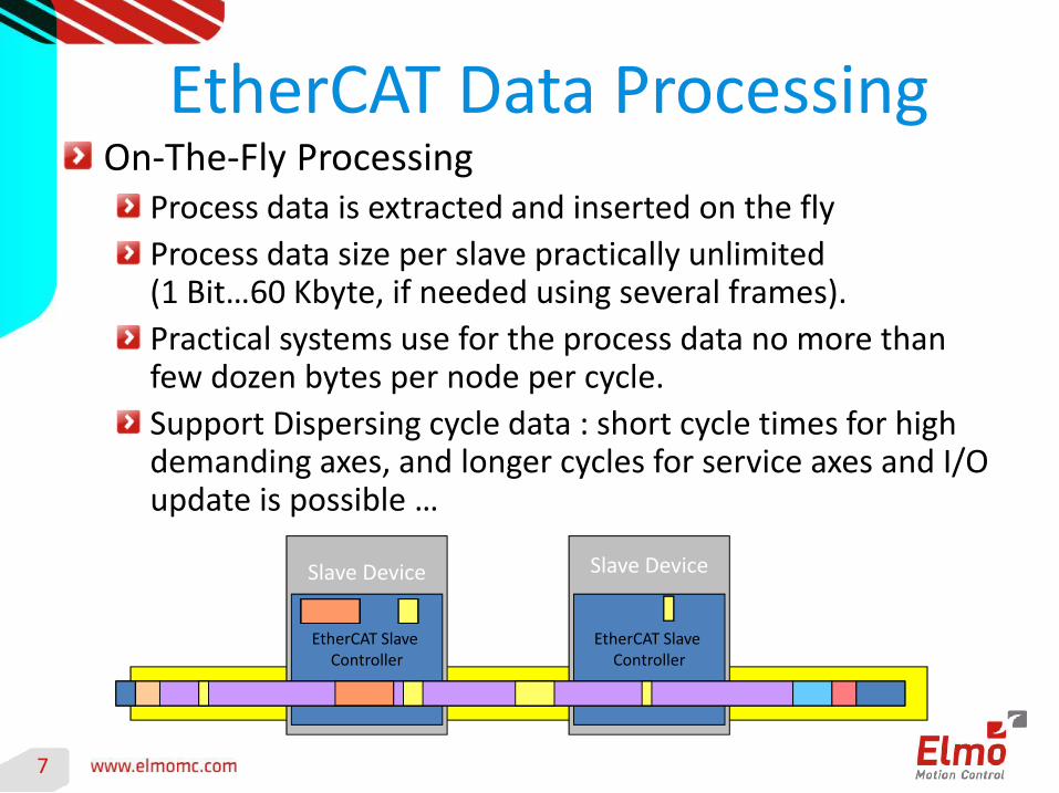
EtherCAT Data ProcessingOn-The-Fly Processing
Process data is extracted and inserted on the fly
Process data size per slave practically unlimited (1 Bit…60 Kbyte, if needed using several frames).
Practical systems use for the process data no more than few dozen bytes per node per cycle.
Support Dispersing cycle data : short cycle times for high demanding axes, and longer cycles for service axes and I/O update is possible …
Slave Device
EtherCAT Slave Controller
Slave Device
EtherCAT Slave Controller
10
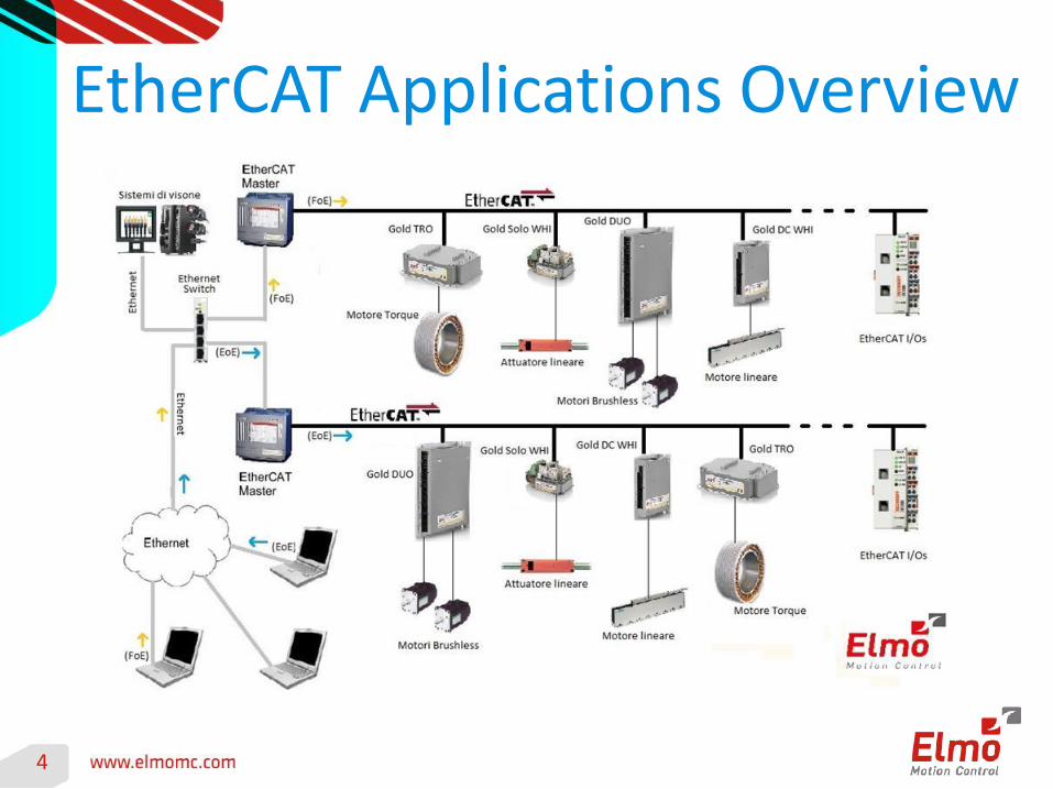
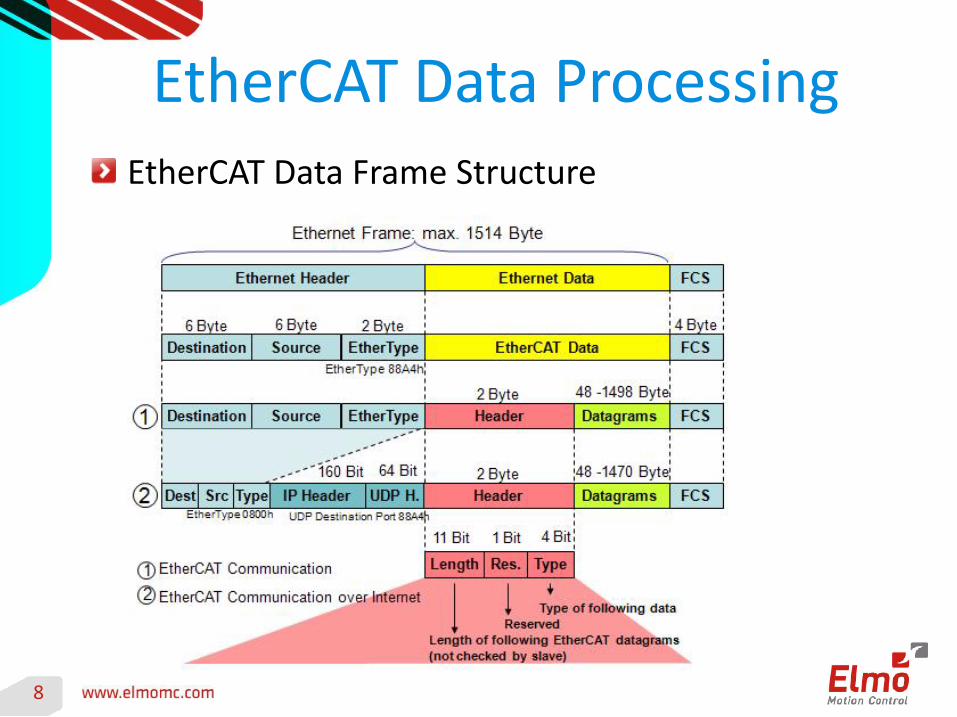
EtherCAT Data Processing
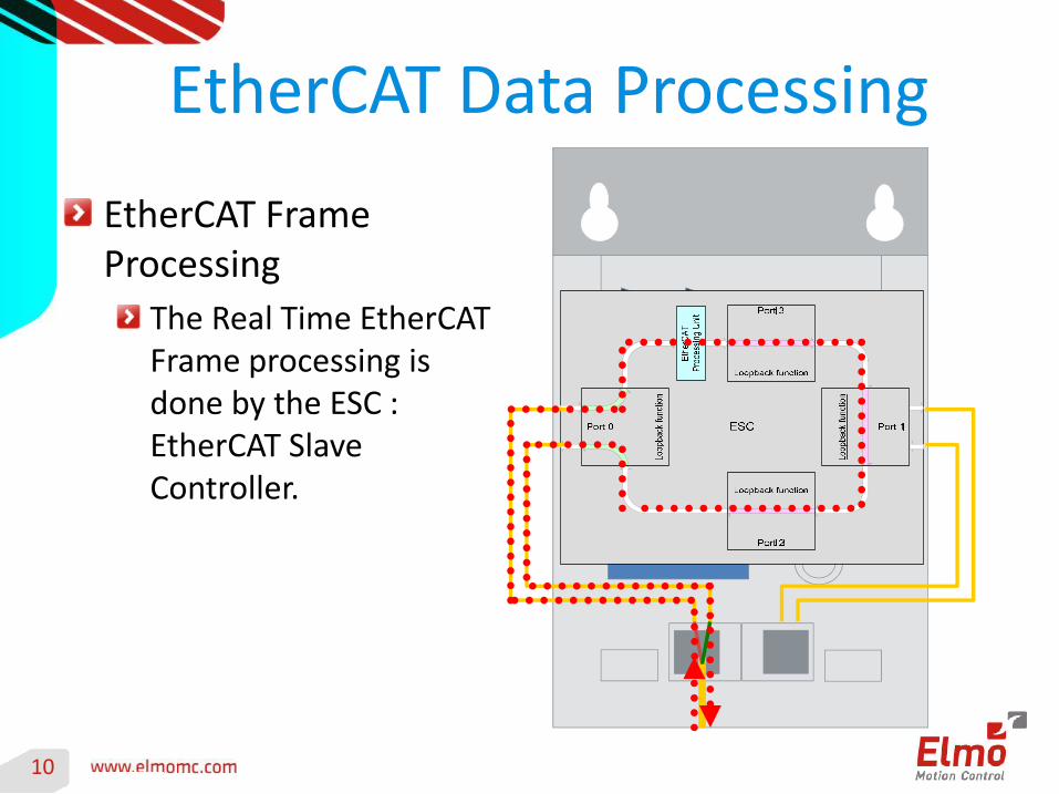
EtherCAT Frame Processing
The Real Time EtherCAT Frame processing is done by the ESC : EtherCAT Slave Controller.
11
EtherCAT Distributed ClocksSynchronization Requirements in Control
Centralized Motion Control Systems use single processor (one servo loop interrupt) for controlling all axes.
Jitter between axes is minimal, and usually relates on h/w latching of peripherals (FPGA etc). This is in the area of few tens of Nano-seconds.
Distributed Control topology comprise of a remote master and multiple slaves, each with its own processing unit, synchronization and timings.
Modern Distributed Motion Control Systems mostly relay on Ethernet based communication links.
Standard Ethernet rallies “too much” on SW, thus its not deterministic enough for real time motion control tasks.
12
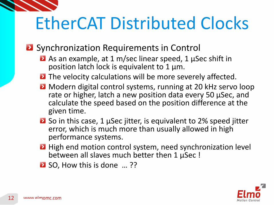
EtherCAT Distributed ClocksSynchronization Requirements in Control
As an example, at 1 m/sec linear speed, 1 μSec shift in position latch lock is equivalent to 1 μm.The velocity calculations will be more severely affected.Modern digital control systems, running at 20 kHz servo loop rate or higher, latch a new position data every 50 μSec, and calculate the speed based on the position difference at the given time.So in this case, 1 μSec jitter, is equivalent to 2% speed jitter error, which is much more than usually allowed in high performance systems.High end motion control system, need synchronization level between all slaves much better then 1 μSec ! SO, How this is done … ??
13
EtherCAT Distributed Clocks
Synchronization in a Distributed SystemThe task of synchronizing multiple clocks in a distributed system is not uniquely specified for Motion Control, and is common for many computer and network systems.
There are few methods to synchronize slave nodes over a network. One common way is the IEEE 1588 precision time protocol (PTP) (defined as early as 2002).
It is a technology for sharing clocks between distributed systems.
IEEE 1588 provides a distributed time base used to timestamp data with sub-microsecond precision.
The EtherCAT Distributed Clock (DC) uses the same concept of distributed time base.
14
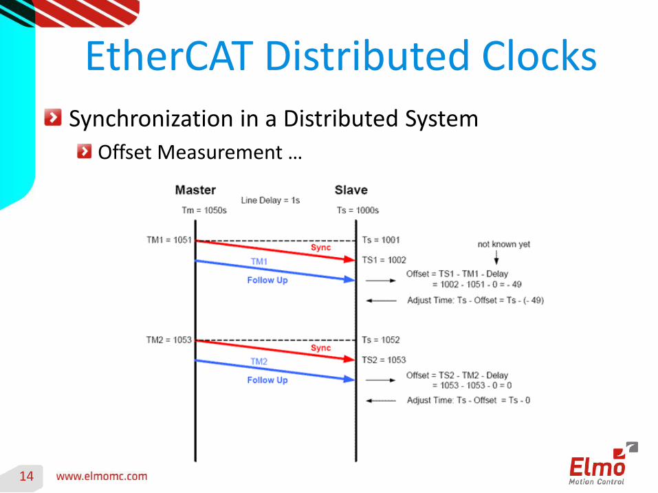
EtherCAT Distributed ClocksSynchronization in a Distributed System
Offset Measurement …
15
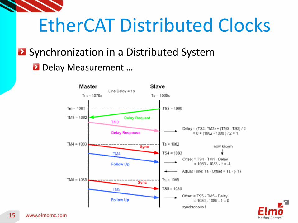
EtherCAT Distributed ClocksSynchronization in a Distributed System
Delay Measurement …
16
EtherCAT Distributed Clocks
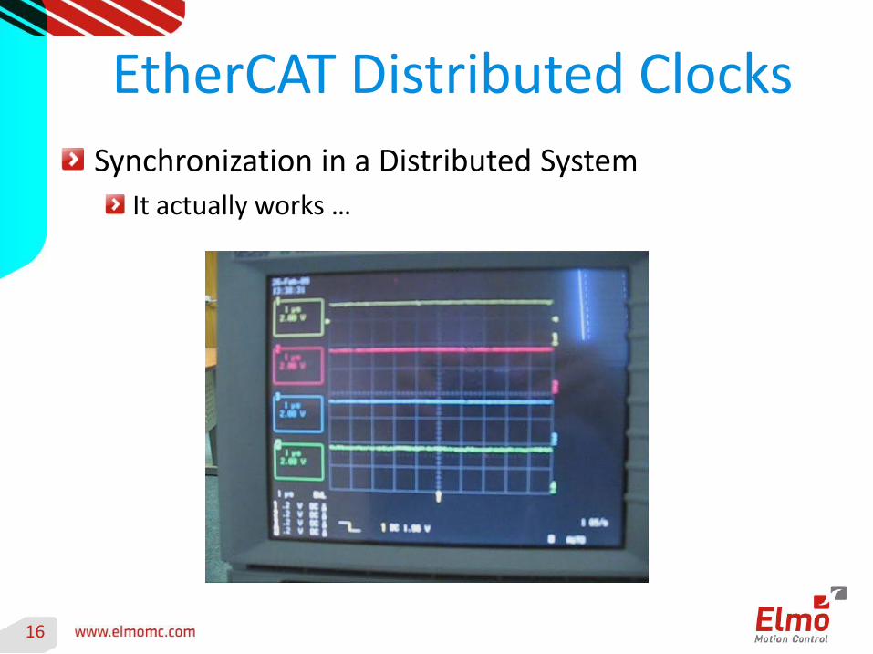
Synchronization in a Distributed System
It actually works …
17
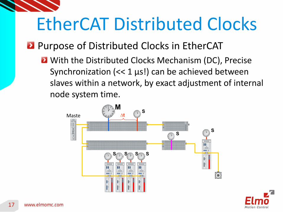
EtherCAT Distributed ClocksPurpose of Distributed Clocks in EtherCAT
With the Distributed Clocks Mechanism (DC), Precise Synchronization (<< 1 µs!) can be achieved between slaves within a network, by exact adjustment of internal node system time.
M∆tIPC
SMaste
r
S
S S S S
S
18
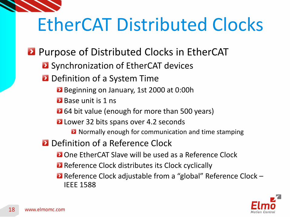
EtherCAT Distributed ClocksPurpose of Distributed Clocks in EtherCAT
Synchronization of EtherCAT devices
Definition of a System TimeBeginning on January, 1st 2000 at 0:00h
Base unit is 1 ns
64 bit value (enough for more than 500 years)
Lower 32 bits spans over 4.2 secondsNormally enough for communication and time stamping
Definition of a Reference ClockOne EtherCAT Slave will be used as a Reference Clock
Reference Clock distributes its Clock cyclically
Reference Clock adjustable from a “global” Reference Clock –IEEE 1588
19
The EtherCAT Slave Controller
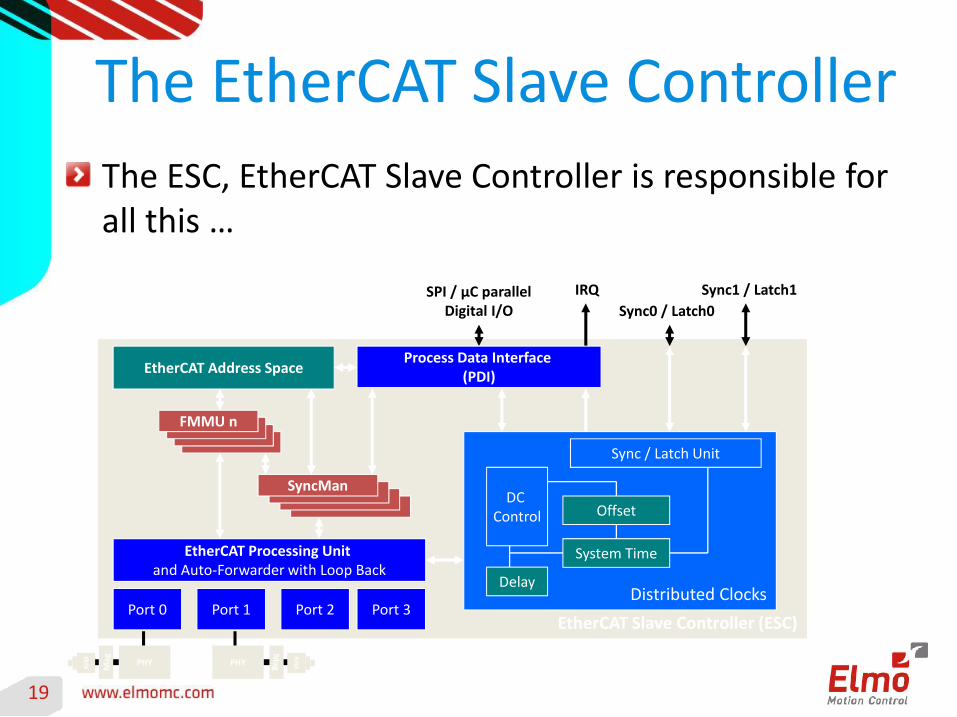
The ESC, EtherCAT Slave Controller is responsible for all this …
EtherCAT Slave Controller (ESC)
FMMU n
SyncMan
EtherCAT Address Space
EtherCAT Processing Unit and Auto-Forwarder with Loop Back
Port 0 Port 1 Port 2 Port 3
PHY
Ma
g
RJ4
5
PHY
Ma
g
RJ4
5
Distributed Clocks
SPI / µC parallelDigital I/O Sync0 / Latch0
Sync1 / Latch1IRQ
Process Data Interface (PDI)
Sync / Latch Unit
DC Control
System Time
Offset
Delay
20
Back to the Motion Control …
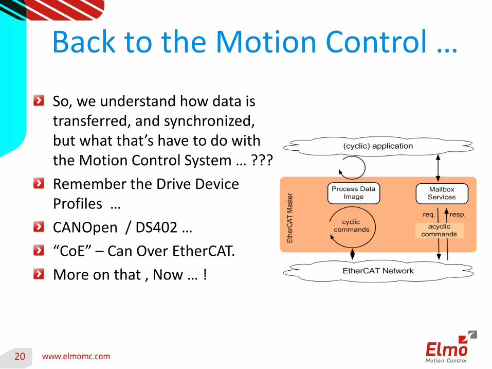
So, we understand how data is transferred, and synchronized, but what that’s have to do with the Motion Control System … ???
Remember the Drive Device Profiles …
CANOpen / DS402 …
“CoE” – Can Over EtherCAT.
More on that , Now … !
21
Servo Drive Device Profile The CANOpen DS402 and CoE
The CAN in AUTOMATION (CiA) Group, established the DS402 (“DS” stands for Draft Standard) for “Drives and Motion Control Device Profile”.
The aim of this standard is to provide a common platform that defines the general behavior, and operation modes that should be supported by drive manufacturers, to enable as much as possible, interoperability between masters and slaves within motion control systems.
It was “born” for the “old” CAN technology, but is widely adopted by the ETG and many drive manufacturers as well, with the CoE … CAN Over EtherCAT.
22
DS402 Drive Device Profile
The CANOpen DS402 and CoE
The DS402 device profile defines several modes of operation, including:
Profile position mode,
Homing modes
Interpolated position mode,
Profile velocity mode,
Profile torque mode,
velocity mode,
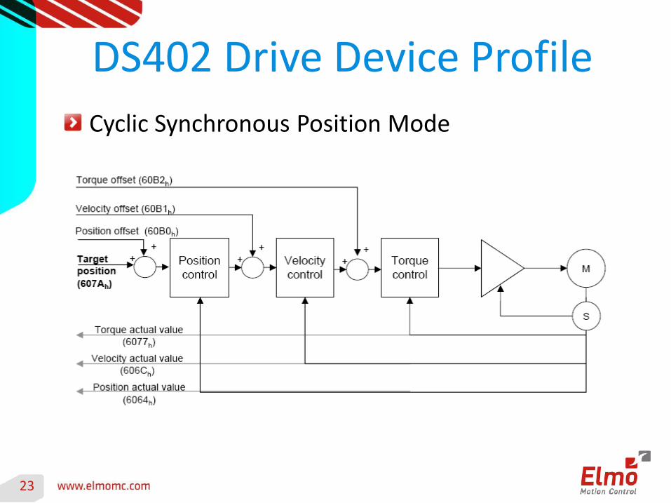
Cyclic synchronous position mode,
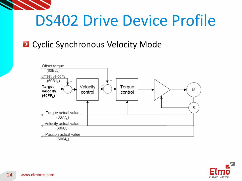
Cyclic synchronous velocity mode, and
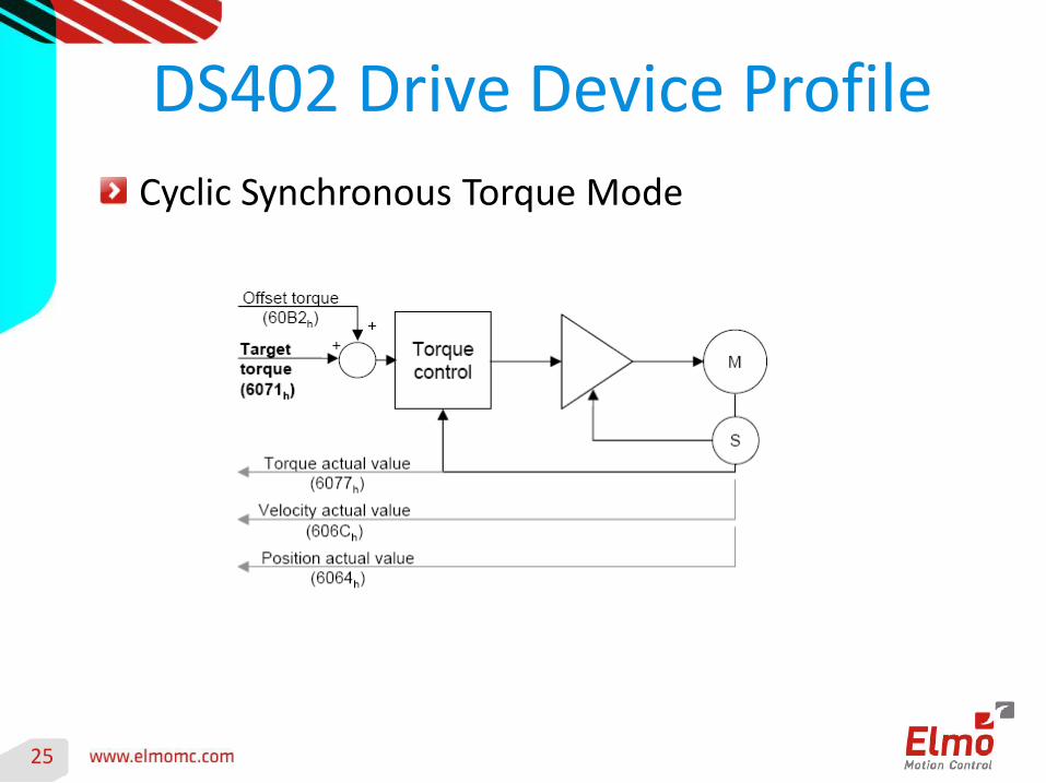
Cyclic synchronous torque mode
26
Real Time Network Inputs/Outputs
So, the data we need to swap between the Master Controller and our Drives, Depends on the “Device Profile” and “Operation Mode” used. It is generally comprised of:
Outputs (from the Master to the Drive): Device Operation Mode Request (CW/OM), Target Position, Target Velcoity, Target Torque, Various Offsets, etc.
Inputs (from the Drive to the Master): Actual Device Operation Mode and status (SW), Actual Position, Actual Velcoity, Actual Torque, etc.
These Data Objects, Periodic or Cyclic Data Objects, aka “PDO’s” : Process Data Objects …
27
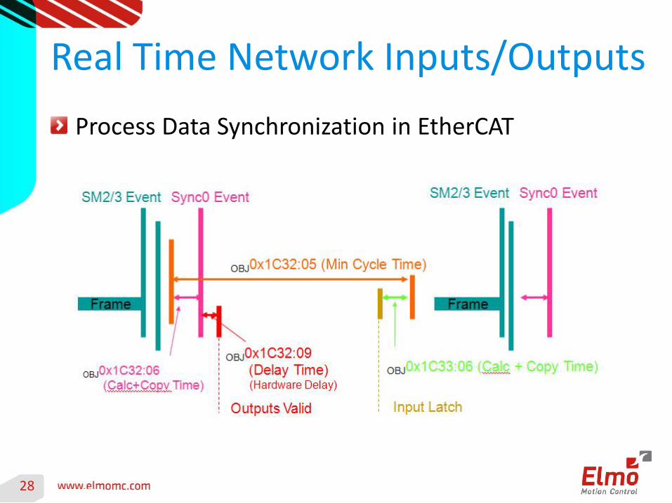
Real Time Network Inputs/Outputs
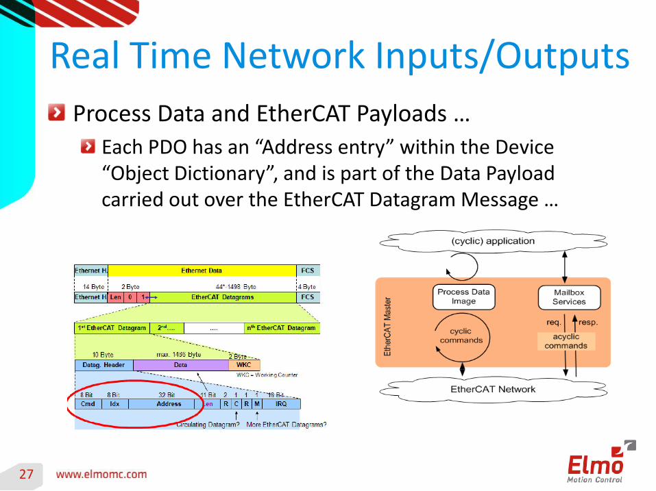
Process Data and EtherCAT Payloads …
Each PDO has an “Address entry” within the Device “Object Dictionary”, and is part of the Data Payload carried out over the EtherCAT Datagram Message …
29
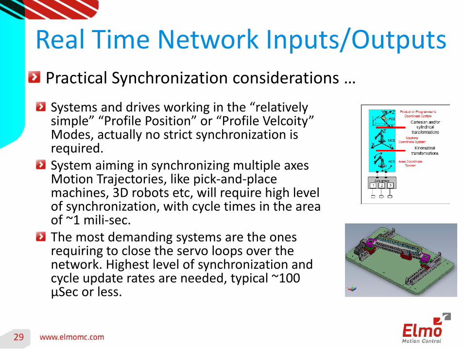
Real Time Network Inputs/OutputsPractical Synchronization considerations …
Systems and drives working in the “relatively simple” “Profile Position” or “Profile Velcoity” Modes, actually no strict synchronization is required.System aiming in synchronizing multiple axes Motion Trajectories, like pick-and-place machines, 3D robots etc, will require high level of synchronization, with cycle times in the area of ~1 mili-sec.The most demanding systems are the ones requiring to close the servo loops over the network. Highest level of synchronization and cycle update rates are needed, typical ~100 μSec or less.
30
Summary
EtherCAT is spreading, in a much faster rate then any other filed bus, and commonly adopted for variety of applications, by many vendors …
The strength of EtherCAT synchronization techniques allows it to be compatible with both low and high demanding applications.
Combined with the correct implementation of both the network protocol, and a proper device profile, a true Distributed Motion control can now be achieved.
Recommended