Embed Size (px)
Citation preview
Elmo Motion Control Ltd. • 60 Amal St., P.O. Box 3078 ,Petach-Tikva 49516, Israel
Tel. +972-3-929-2300 • Fax. +972-3-929-2322 • [email protected] • www.elmomc.com
Elmo’s “Flying Vision”, the Ultimate Solution for
“On-the-Fly” Target Position Corrections
Abstract
Some advanced motion control applications require a change/update of the target position
“On-The-Fly”. Usually, the position change is a result of some position error detected by a
vision measurement system.
The goal is to set the process so that “fast movement towards the final target - capture of the
picture - calculating the correction - execution of the new position” is achieved while moving
and at max possible speed.
The whole throughput of the machine
depends on fast, smooth and stable position
corrections.
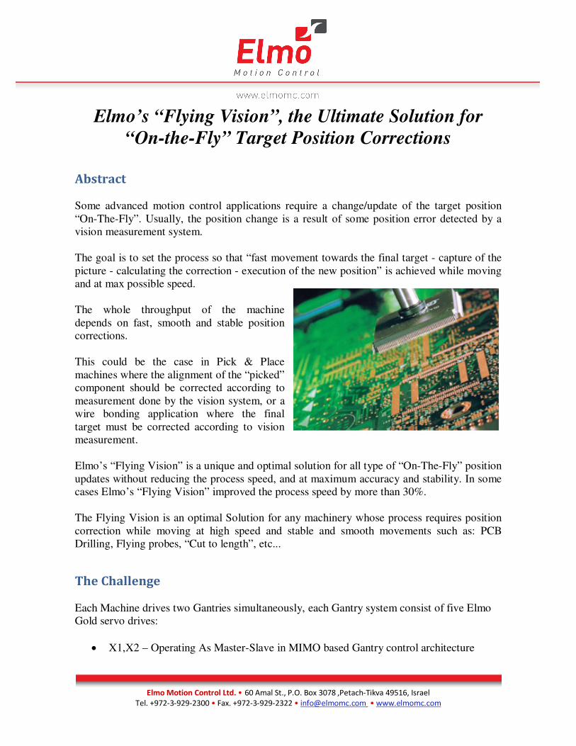
This could be the case in Pick & Place
machines where the alignment of the “picked”
component should be corrected according to
measurement done by the vision system, or a
wire bonding application where the final
target must be corrected according to vision
measurement.
Elmo’s “Flying Vision” is a unique and optimal solution for all type of “On-The-Fly” position
updates without reducing the process speed, and at maximum accuracy and stability. In some
cases Elmo’s “Flying Vision” improved the process speed by more than 30%.
The Flying Vision is an optimal Solution for any machinery whose process requires position
correction while moving at high speed and stable and smooth movements such as: PCB
Drilling, Flying probes, “Cut to length”, etc...
The Challenge
Each Machine drives two Gantries simultaneously, each Gantry system consist of five Elmo
Gold servo drives:
• X1,X2 – Operating As Master-Slave in MIMO based Gantry control architecture
Elmo Motion Control Ltd. • 60 Amal St., P.O. Box 3078 ,Petach-Tikva 49516, Israel
Tel. +972-3-929-2300 • Fax. +972-3-929-2322 • [email protected] • www.elmomc.com
• Y – working as a 2 dimensional
Synchronized MCS (Machine
Coordinate System) grouped axis
with the X1,X2 Gantry axes
• Z – Vertical Axis
• Theta – Advanced miniature Elmo
servo drive for the Rotational axis
All ten drives in the system are operated using a single Elmo Multi axis controller (G-MAS)
via fast deterministic EtherCAT network.
A special fast vision system is located on each Gantry Path, where each SMT Pick & Place
motion trajectory cycle must pass through the constant position and location of the Camera.
This motion must proceed at the highest possible speed and precision. One of the key
elements of this solution is to pass through the camera location from different pick & place
position locations at high speed and smooth motion without stopping it during the Camera
snapshot photo.
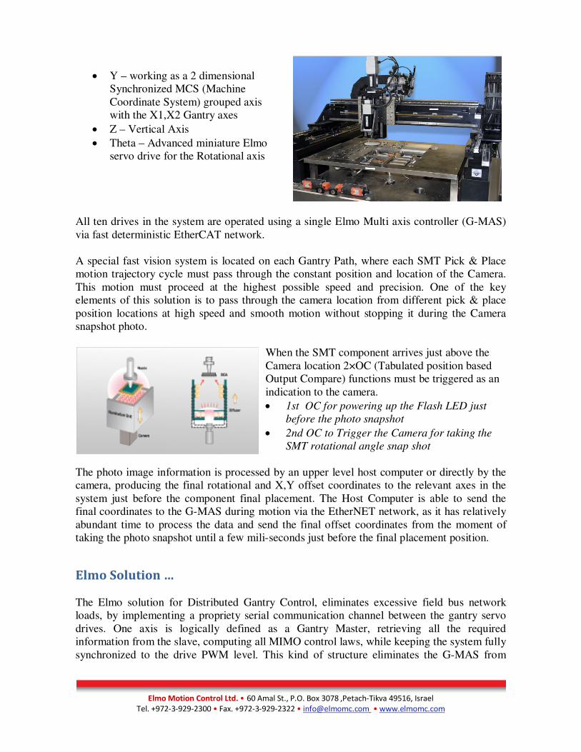
When the SMT component arrives just above the
Camera location 2×OC (Tabulated position based
Output Compare) functions must be triggered as an
indication to the camera.
• 1st OC for powering up the Flash LED just
before the photo snapshot
• 2nd OC to Trigger the Camera for taking the
SMT rotational angle snap shot
The photo image information is processed by an upper level host computer or directly by the
camera, producing the final rotational and X,Y offset coordinates to the relevant axes in the
system just before the component final placement. The Host Computer is able to send the
final coordinates to the G-MAS during motion via the EtherNET network, as it has relatively
abundant time to process the data and send the final offset coordinates from the moment of
taking the photo snapshot until a few mili-seconds just before the final placement position.
Elmo Solution …
The Elmo solution for Distributed Gantry Control, eliminates excessive field bus network
loads, by implementing a propriety serial communication channel between the gantry servo
drives. One axis is logically defined as a Gantry Master, retrieving all the required
information from the slave, computing all MIMO control laws, while keeping the system fully
synchronized to the drive PWM level. This kind of structure eliminates the G-MAS from
Elmo Motion Control Ltd. • 60 Amal St., P.O. Box 3078 ,Petach-Tikva 49516, Israel
Tel. +972-3-929-2300 • Fax. +972-3-929-2322 • [email protected] • www.elmomc.com
handling the Gantry MIMO control algorithm operation and therefore regards the X1, X2
gantry drives as a single X axis drive on the network level. This “single axis” is grouped with
an additional Y axis in order to perform the fast synchronized X, Y 2-dimensional motions of
the machine.
Elmo suggests two possible mechanisms for the solution of this machine. As previously
mentioned, the key element of this solution is to perform highly X,Y synchronized motions
while passing through the camera position location at high speed, and precision, using high
speeds with a smooth motion profile in both Position, velocity and Acceleration/Deceleration.
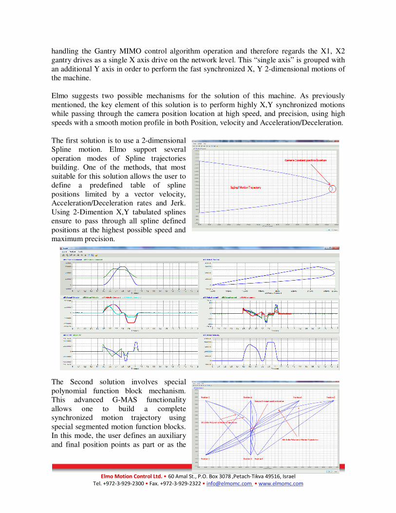
The first solution is to use a 2-dimensional
Spline motion. Elmo support several
operation modes of Spline trajectories
building. One of the methods, that most
suitable for this solution allows the user to
define a predefined table of spline
positions limited by a vector velocity,
Acceleration/Deceleration rates and Jerk.
Using 2-Dimention X,Y tabulated splines
ensure to pass through all spline defined
positions at the highest possible speed and
maximum precision.
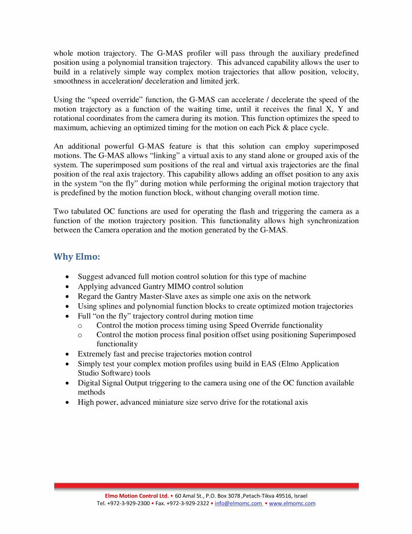
The Second solution involves special
polynomial function block mechanism.
This advanced G-MAS functionality
allows one to build a complete
synchronized motion trajectory using
special segmented motion function blocks.
In this mode, the user defines an auxiliary
and final position points as part or as the
Elmo Motion Control Ltd. • 60 Amal St., P.O. Box 3078 ,Petach-Tikva 49516, Israel
Tel. +972-3-929-2300 • Fax. +972-3-929-2322 • [email protected] • www.elmomc.com
whole motion trajectory. The G-MAS profiler will pass through the auxiliary predefined
position using a polynomial transition trajectory. This advanced capability allows the user to
build in a relatively simple way complex motion trajectories that allow position, velocity,
smoothness in acceleration/ deceleration and limited jerk.
Using the “speed override” function, the G-MAS can accelerate / decelerate the speed of the
motion trajectory as a function of the waiting time, until it receives the final X, Y and
rotational coordinates from the camera during its motion. This function optimizes the speed to
maximum, achieving an optimized timing for the motion on each Pick & place cycle.
An additional powerful G-MAS feature is that this solution can employ superimposed
motions. The G-MAS allows “linking” a virtual axis to any stand alone or grouped axis of the
system. The superimposed sum positions of the real and virtual axis trajectories are the final
position of the real axis trajectory. This capability allows adding an offset position to any axis
in the system “on the fly” during motion while performing the original motion trajectory that
is predefined by the motion function block, without changing overall motion time.
Two tabulated OC functions are used for operating the flash and triggering the camera as a
function of the motion trajectory position. This functionality allows high synchronization
between the Camera operation and the motion generated by the G-MAS.
Why Elmo:
• Suggest advanced full motion control solution for this type of machine
• Applying advanced Gantry MIMO control solution
• Regard the Gantry Master-Slave axes as simple one axis on the network
• Using splines and polynomial function blocks to create optimized motion trajectories
• Full “on the fly” trajectory control during motion time
o Control the motion process timing using Speed Override functionality
o Control the motion process final position offset using positioning Superimposed
functionality
• Extremely fast and precise trajectories motion control
• Simply test your complex motion profiles using build in EAS (Elmo Application
Studio Software) tools
• Digital Signal Output triggering to the camera using one of the OC function available
methods
• High power, advanced miniature size servo drive for the rotational axis