Responsibility cannot be accepted for a failure of this device if the procedures given in this sheet are not imple-mented or if it is used outside the recommended specifica-tions in this sheet.NOTE: The safety inputs of these products are described as normally closed (N.C.), ie. with the guard closed, actuator in place (where relevant) and the machine able to be started. Exposure to shock and/or vibration in excess of those stated in IEC 60068 part: 2-6/7 should be prevented. Adherence to the recommended inspection and maintenance instructions forms part of the warranty.NOTE: All information comply with state of this publication. Subject to change without notice.REPAIR: If there is any malfunction or damage, no attempts or repair should be made. The unit should be replaced be-fore machine operation is allowed. DO NOT DISMANTLE THE UNIT.
Es kann keinerlei Verantwortung für ein Versagen dieses Gerätes übernommen werden, wenn die in diesem Schriftblatt gegebenen Verfahrensweisen nicht implementiert wurden, oder wenn sie außerhalb der auf diesem Schriftblatt empfohle-nen Spezifikationen verwendet werden.HINWEIS: Die Sicherheitskontakte der Schutzvorrichtung sind als Ruhekontakte (N.C.) beschrieben, d.h. bei geschlossener Schutzvorrichtung sind die Betätigungselemente in Position (falls zutreffend) und die Maschine ist startfähig. Eine Aussetzung an Stoßbelastungen und/oder Vibrationen, die über den in IEC 60068, Teil 2-6/7 angegebenen Werten liegen, sollte verhin-dert werden. Die Einhaltung der empfohlenen Inspektions- und Wartungsvor-schriften ist Teil der Garantie.HINWEIS: Alle Angaben entsprechen dem aktuellen Stand der Veröffentli-chung. Änderungen behalten wir uns jederzeit vor.REPARATUR: Bei Fehlfunktion oder Beschädigung dürfen keine Reparaturversuche unternommen werden. Das Gerät muss ersetzt werden, bevor ein weiterer Betrieb der Maschi-ne zugelassen wird. DAS GERÄT DARF NICHT AUSEINANDERGEBAUT WERDEN.
Toda responsabilidad esta declina por averíasen el disposi-tivo resultantes del incumplimiento de las instrucciones expuestas en esta hoja o del uso ajeno a las especificaci-ones aquí recomendadas.NOTA: Los contactos de entrada de estos productos se describen como nor-malmente cerrados (o N.C.), es decir, con el protector cerrado, el accionador en su lugar (si procede) y la máquina en condiciones de arrancar.Deberá evitarse la exposición a golpes o vibraciones superiores a los niveles indicados en la CEI 60068: 2-6/7. El cumplimiento de las instrucciones de inspección y mantenimiento recomendadas forma parte de la garantía.NOTA: Todos los datos se corresponden con la fecha de publicación. Nos reservamos el derecho a introducir cambios sin previo aviso.REPARACIÓN: Si hubiera algún defecto o avería, no intente repararlos. Sustituya la unidad antes de autorizar el funcion-amiento de la máquina. NO DESMONTE LA UNIDAD.
English Deutsch (original)
Warning! ! Warnung ! Advertencia!Danger of serious injuries! Misuse can result in malfunction.
� The device may only be started up, assembled or retrofitted by an authorized and trained personnel.
� Installation must be in accordance with the following steps.
Gefahr von schweren Verletzungen! Durch unsachgemäße Montage kann es zu Fehlfunktionen kommen.
� Die Montage darf nur durch fachlich qualifiziertes Personal erfolgen.
� Die nachfolgend beschriebenen Arbeitsschritte müs-sen eingehalten werden.
Warning!
Danger of serious injuries! Incorrect installation or manipulation can result in serious injuries. � Do not defeat, tamper, remove or bypass this unit.
! WarnungGefahr von schweren Verletzungen!Durch unsachgemäßen Gebrauch kann es zu schweren Verletzungen kommen.� Das Gerät niemals überbrücken.
! Advertencia!Peligro de lesiones graves! La incorrecta instalación o manipulación de este producto puede pro-ducir lesiones graves.� No malogre, manipule, retire ni desvíe esta unidad unità.
Declaration of conformity Konformitätserklärung Declaración de conformidad
Functional Description Funktionsbeschreibung Descripción funcional
Guardmaster Safety Relay GLP10000353605 ver 00, Dwg. No: 95302416, Issue 1, EO: 0412, August 2012
Monitoring Safety Relay - Installation InstructionsSicherheitsrelais - InstallationsanleitungRelé de seguridad de monitorización - Instrucciones de instalación
Peligro de lesiones graves! Un uso incorrecto puede derivar en fallos de funcionamiento.
� El dispositivo sólo podrá arrancar, montarse o adaptarse por personal autorizado y debidamente capacitado.
� La instalación deberá realizarse según los pasos que figuran a continuación.
This device is intended to be part of the safety related control system of a machine.SAFETY NOTESBefore installation, a risk assessment should be performed to determine whether the specifications of this device are sui-table for all foreseeable operational and environmental cha-racteristics of the machine to which it is to be fitted. At regular intervals during the life of the machine check whether the characteristics foreseen remain valid.
Dieses Gerät ist als Teil des sicherheitsrelevanten Kontrollsystems einer Maschine vorgesehen.ALLGEMEINE SICHERHEITSHINWEISEFür die Maschine, in die dieses Gerät eingebaut wird, muss eine Risikobeurteilung durchgeführt werden. Anhand der Ri-sikobeurteilung muss geprüft werden, ob die Spezifikati-onen dieses Geräts den Betriebs- und Umgebungsbedingungen der Maschine entsprechen. In re-gelmäßigen Abständen, während der Lebensdauer der Ma-schine, ist zu überprüfen, ob die vorhergesehenen Spezifikationen weiterhin gültig sind.
Este dispositivo está concebido como parte integrante del sistema de control de seguridad correspondiente de una máquina.INDICACIONES DE SEGURIDADAntes de proceder a la instalación, deberán realizarse estu-dios de riesgos que determinen la idoneidad de las especificaciones de este dispositivo para todas las ca-racterísticas operativas y ambientales previsibles de la má-quina donde va a ser colocado. Revise regularmente la máquina para cerciorarse de que las características previsib-les siguen siendo válidas.
GLP is intended to be used for monitoring and control of guard locking devices based on speed monitoring. The unit is enabled once supply is powered up, the guardlocking safety circuits are closed and monitored speed is below configured safe limited speed. The “PWR” LED is green. Safety outputs are activated by a valid Lock/Reset operation. The Unlock Request initates a shutown or slowdown of the machine and issues an unlock command when the proximity sensors signals are below the configured safe limited speed.RECOVERABLE MINOR ERRORS: Unit can be enabled by removing the fault and a valid sequence of Unlock (S54) and Lock request (S44).RECOVERABLE MAJOR ERRORS: Detected external faults forcing a power cycle of the safety relay module. Diagnostics are available through „PWR/Fault“ LED. NON-RECOVERABLE FAULTS: Malfunction of the unit itself. Cycling power may reset the unit. IF NOT, REPLACE THE UNIT.NOTE: Extended start-up time after power cycle. The device executes self tests and automatic tests of the door and speed monitoring circuit to validate the status of the application.
GLP dient zur Überwachung und Ansteuerung von Zuhaltungen basierend auf der erfassten Geschwindigkeit eines Antriebs. Das Gerät ist betriebsbereit, sobald die Versorgungsspannung eingeschaltet ist, Türüberwachungskreise geschlossen sind und die überwachte Geschwindigkeit unterhalb der eingestellten sicheren Geschwindigkeit liegt. Die „PWR” LED ist grün. Nach gültiger Rücksetzbedingung bzw. Verriegelungskommando werden die Sicherheitsausgänge aktiv. Durch Anfor-derung der Türfreigabe wird die Tür nach Unterschreiten der eingestellten sicheren Geschwindigkeit entriegelt.RÜCKSETZEN WÄHREND DES BETRIEBES: Gerät kann durch Öffnen und Schließen des Türfreigabe-Tasters (S54) und Rücksetz/Verrieglungstatsers (S44), in dieser Reihenfolge, zurückgesetzt werden. (Fehlerquittierung).RÜCKSETZEN NACH ERKENNUNG VON PLAUSIBILITÄTSFEH-LERN DER TÜR UND GESCHWINDIGKEITSÜBERWACHUNG: Erkannte Fehler, die auf einen ungültigen gefährlichen Zustand der Applikation deuten, werden durch Aus- und Einschalten des Gerätes zurückgesetzt. Fehlerdiag-nose erfolgt über „PWR/Fault“ LED.NICHT-BEHEBBARE FEHLER: Mutmaßlicher interner Gerätefehler. Aus- und Einschalten des Gerätes kann unter Umständen diese Fehler zurücksetzen. Falls nicht, muss das Gerät ausgetauscht werden.HINWEIS: Verlängerte Hochlaufzeit nach dem Einschalten. Zur Herstellung der Be-triebsbereitschaft wird eine Eigendiagnose und automatische Plausibilitätsprüfung der Tür und Gschwindigkeitsüberwachung durchgeführt.
El dispositivo está operativo una vez conectada la tensión de alimentación, los cir-cuitos de vigilancia de la puerta cerrados y la velocidad controlada se encuentra por debajo de la velocidad segura ajustada. La LED „PWR“ está verde. Se activan las sali-das de seguridad con una condición de reinicio válida o bien un comando de blo-queo. Requiriendo la liberación de la puerta se desbloquea la puerta en cuanto se baja de la velocidad segura ajustada.REINICIO DURANTE EL FUNCIONAMIENTO: La unidad puede reinici-arse abriendo y cerrando el pulsador de desbloqueo de la puerta (S54) y el pulsador de reinicio/bloqueo (S44), por este orden (reconocimiento de error).REINICIO DESPUÉS DEL RECONOCIMIENTO DE ERRORES DE VEROSIMILITUD DE LA PUERTA Y CONTROL DE VELOCIDAD: Errores reconocidos que indican un estado peligroso no válido de la aplicación se retroceden apagando y encendiendo el dispositivo. El diagnóstico de error se realiza a través de la LED „PWR/Fault“.ERRORES NO SUBSANABLES: El apagado y encendido del dispositivo puede subsanar estos errores. Si no es así debe sustituirse el dispositivo.INDICACIÓN: Tiempo de puesta en funcionamiento prolongado después del encen-dido. Para el establecimiento de la disponibilidad operacional se lleva a cabo un di-agnóstico propio y una prueba de verisimilitud de la puerta y un control de velocidad.
Rockwell Automation hereby declares that Guardmaster GLP is in con-formity with Directive(s) 2006/95/EC, 2004/108/EC 98/37/EC, 2006/
42/EC as specified in the Declaration of Conformity available from www.rock-wellautomation.com/ products/ certification
Hiermit erklärt Rockwell Automation, dass Guardmaster GLP wie in der Konformitätserklärung angegeben, den Richtlinien 2006/95/EG,
2004/108/EG, 98/37/EG, 2006/42/EG genügt, erhältlich unter www.rockwellautomation.com/products/certification
Rockwell Automation declara por la presente que el Guardmaster GLP cumple las directivas 2006/95/EC, 2004/108/EC, 98/37/EC, 2006/42/
EC según se especifica en la Declaración de conformidad. Para obtenerla, visite www.rockwellautomation.com/products/certification
Español
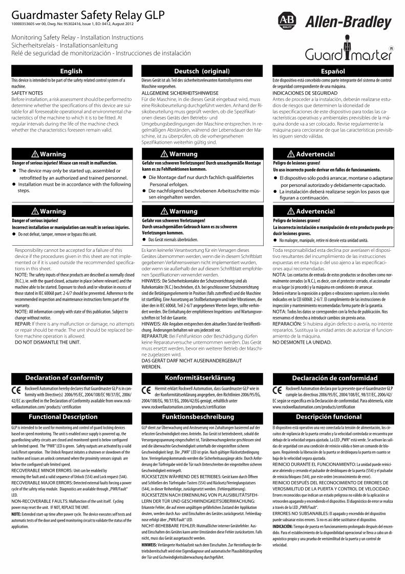
Start configuration with power off.
1. Turn the Logic rotary switch to 0 or to 9 if the safety input device will use the test outputs. Set the SL1 and SL2 rotary switches. Due to the overspeed detection time, speed limits shall be set lower than the maximum allowable speed limit.Note: Guard locking switch must be connected.2. Turn on the power and wait for the PWR LED to flash red. 3. Rotate the Logic switch to the desired position.Note: The IN1 LED blinks the Logic Position. The LOCK LED blinks theSL1 position and the Logic IN LED blinks the SL2 position. The OUT LEDblinks the solenoid type on L61, 51 and X14, X24 configuration.Note: The position is set when the PWR LED is solid green.4. Lock in the configuration by cycling the power.Configuration must be confirmed before operation. 5. A space on the front of the the device is provided to record the settings.
1 Category 1 Stop Logic in OFF2 Category 1 Stop Logic in AND3 Safe Limited Speed Logic in OFF4 Safe Limited Speed Logic in AND
5 Reserved for future use6 Reserved for future use7 Reserved for future use8 Reserved for future use
5 200 Hz0 No MAX Speed Monitoring6 500 Hz1 10 Hz7 1000 Hz2 20 Hz8 2000 Hz3 50 Hz9 3000 Hz4 100 Hz
0 0.5 Hz1 1 Hz2 2 Hz3 3 Hz4 4 Hz
5 5 Hz6 6 Hz7 7 Hz8 8 Hz9 10 Hz
L2L1L
Category 1 stop Safe limited speed
EMS12 S22L61
LockX1451 X24
L11L12GLP
A1
S12 S22L61X1451 X24
L11L12GLPLock
A1
PNP OSSD
A2
TLSZR
S12 S22L61X1451 X24
L11L12GLPLock
Logic Logik Lógica GLP operates in two modes, Stop Cat 1 and Safe Limited Speed. Two speed limits can be set, SL1 for safe speed limit and SL 2 for max. speed limit. The oprating function (LOGIC) and the speed limits (SL1, SL2) are configured as shown in table below. The logic between the two safety inputs IN1 (S12, S22) and the single wire safety input (L12) can be confi gured to the optionsshown table below.
GLP arbeitet in den Betriebsarten Stop Kategorie 1 oder sichere begrenzte Geschwindigkeit. Zwei Geschwindig-keiten werden überwacht, die sicher begrenzte Geschwin-digkeit SL 1 und die maximale Geschwindigkeit im Betrieb, SL2. Die Betriebsart (LOGIC) und die Geschwindigkeitsgren-zen (SL1, SL2) werden, wie unten beschrieben, konfiguriert. Die Logik zwischen den Sicherheitseingängen IN1 (S12, S22) und dem dynamischen Sicherheitseingang L12 wird wie un-ten angegeben konfiguriert.
El modo operativo (lógica), la velocidad segura (SL1) y la velocidad máxima de funcionamiento (SL2) deben confi-gurarse como se describe más abajo. La lógica entre las dos entradas de seguridad IN1 (S12, S22) y la entrada de seguri-dad de un solo cable (L12) se puede configurar para en la ta-bla.
Configuration Konfiguration Configuración Vor Start/Überschreiben der Konfiguration Gerät ausschalten.1. Logic Drehschalter in Position “0“ bringen oder Position „9“, wenn die Sicherheitseingänge Testausgänge erfordern. Setzen der Drehschalter SL1 und SL2. Aufgrund der Ant-wortzeit auf Geschwindigkeitsüberschreitungen, soll die eingestellte Geschwindigkeit unterhalb der maximal zuläs-sigen Geschwindigkeitsgrenzen liegen.HINWEIS: Verriegelungsschalter muss verdrahtet sein.2. Gerät einschalten. “PWR“ -LED blinkt rot.3. Logic Drehschalter auf gewünschte Position drehen.Hinweis: IN1 LED zeigt Logic Position, LOCK LED zeigt SL1 Position und LOGIC IN LED zeigt SL2 Position. Die OUT LED zeigt die Konfiguration von X14, X24 und die Art des Verrigelungsschalters an L61, 51.Hinweis: Die PWR LED wechselt zu grün, wenn die Konfiguration übernom-men wurde.4. Konfiguration bestätigen: Ausschalten und erneutes Einschalten des Gerätes.5. Eine Positionsüberprüfung vor dem Einsatz ist erforder-lich. Dazu steht das freie Feld auf dem Front zum Ausfüllen zur Verfügung.
Antes del inicio/sobregrabación de la configuración apagar el disposi-tivo. 1. Situar el interruptor giratorio lógico en la posición „0“ ó en la posición „9“ cuando las entradas de seguridad preci-san salidas de prueba. Colocar los interruptores giratorios SL1 y SL2.NOTA: El combinador de interconexión debe estar cableado2. Encender el dispositivo la LED „PWR“ parpadea en rojo. 3. Girar el interruptor giratorio lógico a la posición deseada. NOTA: La LED IN1 (entrada 1) indica la posición LOGIC (lógica), la LED LOCK (bloqueo) indica la posición SL1 y la LED LOGIC IN indica la posición SL2. La LED OUT (salida) indica la configuración de X14, X24 y el modo del combina-dor de interconexión en L61, 51. 4. Confirmar la configuración: Apagar y volver a encender el dispositivo. 5. Es necesario un control de posición antes de la puesta en servicio. Para eso está disponible la casilla libre frontal.
L
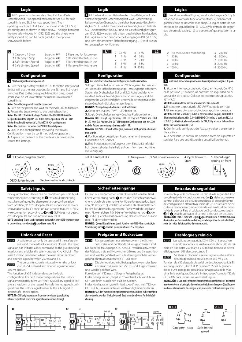
Safety Inputs Sicherheitseingänge Entradas de seguridadOne guardlocking device can be monitored per unit. For 4-wire connections according to cross fault monitoring must be configured by alternate start-up configuration from position „9“. Cross loop faults are monitored as major recoverable faults. Connection can achieve max. PL e. For 2-wire connection according to or GLP does not detect cross loop faults and can achieve max. PL d.NOTE: Cross loop faults can be detected by switches with OSSD characteristics in connections according to to achieve max. PL e.
Es kann nur ein Sicherheitskreis überwacht werden. Bei 4-Leiter Verdrahtung nach muss die Querschlussüberwa-chung durch die alternative Konfigurationsprozedur, Start von „9“, aktiviert. Querschlüsse werden als Plausibilitätsfeh-ler der Türüberwachung erkannt. Diese Verdrahtung kann max. PL e erreichen. Für 2-Leiter Verdrahtung nach oder ist die Querschlussüberwachung deaktiviert und es kann max. PL d erreicht werden.HINWEIS: Querschlüsse können durch Schalter mit OSSD-Charakteristik, in Verdrahtung nach erkannt werden und max. PL e erreichen.
Solamente puede controlarse un circuito de seguridad. Con un cableado de 4 conductores según debe activarse el control del cruce de circuitos mediante el procedimiento de configuración alternativo, inicio de „9“. Los cruces de cir-cuito se reconocen como errores de verisimilitud del cont-rol de la puerta. Para el cableado de 2 conductores según ó está desactivado el control del cruce de circuitos.INDICACIÓN: Para el cableado según puede realizarse el control del cruce de circuitos, en función de la modalidad, por el dispositivo de entrada (OSSD, señal de salida del dispositivo de conmutación).
Unlock and Reset Freigabe und Rücksetzen Desbloque y reinicioA valid reset can only be operated if the safety cir-cuits and the feedback circuit are closed. The reset
signal on S44 initiates a lock command to the guardlocking interlock and enables the safety outputs X14, X24, L11. The reset function is initiated when the reset circuit is closed and opened again between 250 ms and 3 s.
The unlock function is initiated when the unlock circuit S54 is closed and opened again between
250 ms and 3 s.The function of Y32 is dependent on the logic configuration. For cat 1 stop configurations, the unlock signal immediately turns OFF the Y32 auxiliary signal to init-iate a shutdown of the hazard. For safe limited speed confi-gurations, the unlock signal turns ON the Y32 signal to initiate safe limited speed.NOTE: The GLP only operates with power-to-release guardlockinginterlocks (without protection against unintentional closing).
Rücksetzen kann nur erfolgen, wenn die Sicher-heitskreise und der Rückführkreis geschlossen sind.
Die Sicherheitsausgänge X14, X24, L11 werden aktiv, wenn der Rücksetzkreis an S44 zwischen 250 ms und 3 s geschlos-sen und wieder geöffnet wird. Gleichzeitig wird die Verrie-gelung durch abschalten von 51, L61 aktiv.
Die Verriegelung wird freigegeben, wenn der Steu-erkreis an S54 zwischen 250 ms und 3 s geschlossen
und wieder geöffnet wird.Funktion von Y32 nach gültigem Freigabesignal:In der Konfiguration „Stop Cat 1“ wechselt Y32 von ON zu OFF um einen Maschinen-Halt einzuleiten. In der Konfiguration „safe limited speed“ wechselt Y32 von OFF zu ON, um eine sichere Geschwindigkeit einzuleiten.HINWEIS: GLP darf nur mit Verriegelungsschaltern nach dem Ruhestromprin-zip verwendet werden (Freigabe durch Bestromen) und ohne Fehlschließsi-cherung.
Las salidas de seguridad X14, X24, L11 se activan cuando se cierra y se vuelve a abrir el circuito de rei-
nicio en S44 entre 250 ms y 3 s. Al mismo tiempo se activa el bloqueo en L61 desconectando 51.
Se libera el bloqueo si se cierra y se vuelve a abrir el circuito de mando en S54 entre 250 ms y 3 s.
Función de Y32 después de señal de desbloqueo válida: En la configuración „Stop Cat 1“ cambia Y32 de ON (encen-dido) a OFF (apagado) para iniciar una parada de la máq-uina. En la configuración „safe limited speed“ cambia Y32 de OFF a ON para iniciar una velocidad segura.INDICACIÓN: El GLP debe emplearse solamente con combinadores de interco-nexión conforme al principio de corriente de régimen de reposo (desbloqueo mediante alimentación de energía) y sin protección contra el cierre por error.
1 1
2 3
1
32
33
233
L L
C CC
1. Enable program mode;
OSSD Safety Inputs Electromechanical contacts
OR
2. Turn power ON
3. Set operation mode 4. Cycle Power to Store
5. Record logic setting on front
set SL1 and set SL2
3-Wire DC Prox
max. 0.5..0.8 x Snmin. 3 x Sn
d3d
2d
SpaceMark
Prox
4d
d
Prox
BrownBlack (PNP)Blue
Brown
(0V) Common
Black (PNP)Blue
Prox
Prox
AP A2P22P12
TM (PTI) [a] 20
dop [d] / hop [h]1 365 / 24
tcycle [h]/[s]2 8 / 28.800
EN ISO 13849-1 IEC 61508/IEC 62061
PL d SIL 3
MTTFd [a] 395 PFH [1/h] 7.18 x 10⁻⁹
Cat. 3 HFT 1
DC avg. 98 % DC 98 %
1 Operation time (day, hour), Betriebs-zeit (Tag, Stunde) / Tiempo operativo (día, hora) 2 Cycle time (hour, sec), Anforderungs-rate (Stunde, Sek) / Tiempo de ciclo (hora, seg)
Channel 1
Channel 2
Sensor Contact Actuator 1
e.g. Interlock TLS-GD2
Safety Relay GLP e.g. Safe OFF PF7x
Sensor Contact Actuator 2
Technical Support / Technische Unterstützung / Assistance technique / Assistenza tecnica / Asistencia técnica
ENGLISHDEUTSCHFRANÇAISITALIANOESPAÑOLPORTUGUÊSPOLSKIČESKYSVENSKANEDERLANDS
БЪЛГАРСКИEESTISUOMIΕΛΛΗΝΙΚΆMAGYARÍSLENSKALATVIEŠU VALODALIETUVIRŠKAIMALTINORSKROMÂNĂSLOVENSKYSLOVENŠČINATÜRKÇE
Installation of this product must not take place until the installer has obtained a copy of the manufacturer’s instructions in a language which he can understand. This instruction sheet is available in multiple languages at http://rockwellautomation.com/literature.Dieses Produkt darf erst installiert werden, wenn der Installateur eine Kopie der Instruktionen des Herstellers in der Sprache eingeholt hat, die er versteht. Diese Instruktionen sind mehrsprachig erhältlich unter: http://rockwellautomation.com/literature.
Non si deve procedere all’installazione di questo prodotto fin quando l’installatore non abbia ottenuto una copia delle istruzioni del produttore in una lingua che l’installatore possa capire. La presente scheda di istruzioni è disponibile in linguaggi multipli sul sito web http://rockwellautomation.com/literature.Absténgase de instalar este producto a menos que el instalador disponga de un ejemplar de las instrucciones del fabricante en un idioma que pueda comprender. En http://rockwellautomation.com/literature puede encontrar esta hoja de instrucciones en varios idiomas.A instalação deste produto não pode ser efectuada até que o montador tenha obtido uma cópia das instruções do fabricante numa língua que ele compreenda. Essa folha de instruções está disponível em diversas línguas em http://rockwellautomation.com/literature.Nie należy przeprowadzać instalacji tego produktu aż do otrzymania przez montera instrukcji producenta w języku, który on rozumie. Te karty z instrukcjami są dostępne w wielu językach na: http://rockwellautomation.com/literature.Instalace tohoto výrobku nesmí proběhnout, dokud instalující osoba neobdrží pokyny výrobce v jazyce, kterému rozumí. Tyto pokyny jsou k dispozici v několika jazycích na http://rockwellautomation.com/literature.
Het product mag pas worden geïnstalleerd wanneer de monteur beschikt over een exemplaar van de instructies van de fabrikant in een voor hem begrijpelijke taal. Dit instructieblad is in diverse talen verkrijgbaar op http://rockwellautomation.com/literature.: http://rockwellautomation.com/literature: http://rockwellautomation.com/literature
http://rockwellautomation.com/literature Това устройство не трябва да се монтира, докато монтажника не разполага с инструкциите на производителя, на разбираем за него език. Инструкциите за монтаж ще намерите на различни езици в http://rockwellautomation.com/literature.Selle toote installatsioon ei tohi toimuda enne kui installeerija on omandanud koopia tootja instruktsioonidega keeles mida ta ise valdab. Instruktsioonid erinvates keeltes on saadaval siin: http://rockwellautomation.com/literature.Tämä tuote voidaan asentaa vasta kun asentaja on hankkinut valmistajan ohjeet kielellä, jota hän ymmärtää. Erikieliset ohjeet ovat ladattavissa sivustolta http://rockwellautomation.com/literature.Εγκατάσταση του προϊόντος αυτού δεν πρέπει να γίνει πριν ο εγκαταστάτης προμηθευθεί αντίτυπο οδηγιών του κατασκευαστή σε γλώσσα που ο ίδιος καταλαβαίνει. Το εγχειρίδιο αυτό διατίθεται σε διόφορες γλώσσες στη διεύθυνση http://rockwellautomation.com/literature.Ez a termék csak akkor helyezhető üzembe, ha az üzembehelyezést végző személy rendelkezésére áll a gyártó használati utasítása az általa ismert nyelven. Az utasítás több nyelven megtalálható itt: http://rockwellautomation.com/literature Uppsetning á þessari vöru má ekki eiga sér stað fyrr en sá sem annast uppsetninguna hefur fengið afrit af leiðbeiningum framleiðanda á því tungumáli sem hann þekkir. Leiðbeiningarpésinn er tiltækur á mörgum tungumálum og er hægt að ná í hann hér: http://rockwellautomation.com/literatureŠī ražojuma uzstādīšanu nedrīkst veikt, pirms uzstādītājs nav saņēmis ražotāja instrukcijas tādā valodā ko viņš saprot. Šo instrukciju lapiņu var saņemt daudzās valodās no vietnes http://rockwellautomation.com/literatureŠito produkto įrengimas negali būti vykdomas tol, kol įrengėjas neturės gamintojo instrukcijų kopijos ta kalba, kurią jis supranta. Instrukciją galima rasti įvairiomis kalbomis tinklapyje http://rockwellautomation.com/literatureL-installazzjoni ta’ dan il-prodott mgħandux isir qabel ma l-installatur jakwista kopja tal-istruzzjonijiet tal-manifattur f ’lingwa li tista’ tiftiehem. Il-karta tal-istruzzjonijiet hija disponibbli f ’ħafna lingwi f ’http://rockwellautomation.com/literature.
Inštalácia tohto výrobku nesmie prebehnúť, dokiaľ inštalujúca osoba nedostane pokyny výrobca v jazyku ktorému rozumie. Tieto pokyny sú k dispozícii v niekoľkých jazykoch na http://rockwellautomation.com/literature.Tega izdelka se ne sme nameščati, če si oseba, ki ga namešča, ni priskrbela izvoda proizvajalčevih navodil v jeziku, ki ga razume. Ta list z navodili v številnih jezikih je na razpolago na http://rockwellautomation.com/literature.Bu ürünün kurulmasının, ürünü kuracak kişinin üreticinin hazırladığı talimatların bir kopyasını, ki bu talimatlar bu kişinin anlayacağı bir dilde olacaktır, elde edene kadar gerçekleşmemesi gerekir. Bu talimatlar pek çok dilde şu web-sayfasında mevcuttur: http://rockwellautomation.com/literature
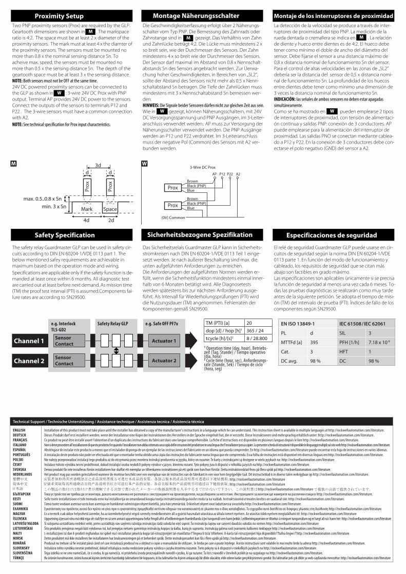
Proximity Setup Montage Näherungsschalter Montaje de los interruptores de proximidadTwo PNP proximity sensors (Prox) are required by the GLP. Geartooth dimensions are shown in . The markspace ratio is 4:2. The space must be at least 2 x diameter of the proximity sensors. The mark must at least 4 x the diamter of the proximity sensors. The sensors must be mounted no more than 0.8 x the nominal sensing distance Sn. To acheive max. speed, the sensors must be mounted no more than 0.5 x the sensing distance Sn. The depth of the geartooth space must be at least 3 x the sensing distance.NOTE: Both sensors must not be OFF at the same time.24V DC powered proximity sensors can be connected to the GLP as shown in : 3-wire 24V DC Prox with PNP output. Terminal AP provides 24V DC power to the sensors. Connect the outputs of the sensors to terminals P12 and P22 . The 3-wire sensors must have a common connection with A2.NOTE: See technical specification for Prox input characteristics.
Die Geschwindigkeitserfassung erfolgt über 2 Näherungs-schalter vom Typ PNP. Die Bemessung des Zahnrads oder Zahnstange sind in gezeigt. Das Verhältnis von Zahn und Zahnlücke beträgt 4:2. Die Lücke muss mindestens 2 x so breit sein, wie der Durchmesser des Sensors. Der Zahn mindestens 4 x so breit wie der Durchmesser des Sensors. Der Sensor darf maximal im Abstand von 0.8 x Nennschalt-abstands Sn des Sensors angebracht werden. Zur Üerwa-chung hoher Geschwindigkeiten, in Bereichen von „SL2“, sollte der Abstand des Sensors nicht mehr als 0.5 x Nenn-schaltabstand Sn betragen. Die Tiefe der Zahnlücken muss mindestens mit 3 x Nennschaltabstand Sn bemessen wer-den.HINWEIS: Die Signale beider Sensoren dürfen nicht zur gleichen Zeit aus sein.Wie in gezeigt, können Näherungsschaltern, mit 24V DC Versorgungsspannung und PNP Ausgängen, im 3-Leiter-anschluss verwendet werden:. AP muss zur Versorgung der Näherungsschalter verwendet werden. Die PNP Ausgänge werden an P12 und P22 verdrahtet. Im 3-Leiteranschluss muss der negative Pol (Common) des Sensors mit A2 ver-bunden werden.
La detección de la velocidad se produce a través de inter-ruptores de proximidad del tipo PNP. La medición de la rueda dentada o cremallera se indica en . La relación de diente y hueco entre dientes es de 4:2. El hueco debe tener como mínimo el doble de ancho del diámetro del sensor. Debe fijarse el sensor a una distancia máximo de 0,8 x distancia nominal de funcionamiento Sn del sensor. Para el control de altas velocidades en las zonas de „SL2“ debería ser la distancia del sensor de 0,5 x distancia nomi-nal de funcionamiento Sn. La profundidad de los huecos entre dientes debe tener como mínimo una dimensión de 3 veces la distancia nominal de funcionamiento Sn.INDICACIÓN: las señales de ambos sensores no deben estar apagadas simultáneamente.Como se ha mostrado en pueden emplearse 2 tipos de interruptores de proximidad, con tensión de alimentaci-ón continua y salidas PNP: conexión de 3 conductores. AP puede emplearse para la alimentación del interruptor de proximidad. Las salidas PNO se conectan mediante cablea-do a P12 y P22. En la conexión de 3 conductores debe con-ectarse el polo negativo (GND) del sensor a A2.
MM M
W
W W
The safety relay Guardmaster GLP can be used in safety cir-cuits according to DIN EN 60204-1/VDE 0113 part 1. The below mentioned safey requirements are achievable in maximum based on the operation mode and wiring.Specifications are applicable only if the safety function is de-manded at least once within 6 months. All diagnostic test are carried out at least before next demand. As mission time (TM) the proof test interval (PTI) is assumed.Components fai-lure rates are according to SN29500.
Das Sicherheitsrelais Guardmaster GLP kann in Sicherheits-stromkreisen nach DIN EN 60204-1/VDE 0113 Teil 1 einge-setzt werden. Je nach äußerer Beschaltung sind max. die unten aufgeführten Anforderungen zu erreichen.Die Anforderungen der aufgeführten Normen werden er-füllt, wenn die Sicherheitsfunktion mindestens einmal inner-halb von 6 Monaten betätigt wird. Alle Diagnosetests werden spätestens bis zur nächsten Anforderung ausge-führt. Als Intervall für Wiederholungsprüfungen (PTI) wird die Nutzungsdauer (TM) angenommen. Fehlerraten der Komponenten gemäß SN29500.
El relé de seguridad Guardmaster GLP puede usarse en cir-cuitos de seguridad según la norma DIN EN 60204-1/VDE 0113 parte 1. En función del modo de funcionamiento y cableado, los requisitos de seguridad que se citan más abajo son factibles en grado máximo. Las especificaciones son aplicables únicamente si se precisa la función de seguridad al menos una vez cada 6 meses. To-das las pruebas diagnósticas se realizarán como muy tarde antes de la siguiente petición. Se adopta el tiempo de misi-ón (TM) del intervalo de prueba (PTI). Índices de fallo de los componentes según SN29500.
Safety Specification Sicherheitsbezogene Spezifikation Especificaciones de seguridad

Power supply Spannungsversorgung Alimentation
Ub: 24 V DC PELV / SELV according to IEC 60204 and IEC 61558-10.85 to 1.1 x rated voltage
Ub: 24 V DC PELV / SELV gem äß IEC 60204 und IEC 61558-10,85 bis 1,1 x Nennspannung
Ub: 24 V DC PELV / SELV de acuerdo IEC 60204 e IEC 61558-10,85 à 1,1 x voltaje nominal
Power consumption Leistungsverbrauch Consumo eléctrico
2.5 W 2.5 W 2.5 W
Fuse Power Supply Sicherung Spannungsversorgung Fusibles Alimentación (externos)
4A gG, tripping characteristic B or C 4A gG, Ansprechverhalten B oder C 4A gG, on características de disparo Bo C
Inputs Eingänge Entradas
Safety: (S12, S22) 1 NC, 2 NC, 1 PNP OSSD or 2 PNP OSSDSpeed Sensor: (P12, P22) 2 PNPReset: S44, Unlock: S54
Sicherheitseingänge: (S12, S22) 1 NC, 2 NC, 1 PNP OSSD oder 2 PNP OSSDGeschwindigkeitsensor: (P12, P22) 2 PNPRücksetzen: S44, Freigabe: S54
Entradas de seguridad: (S12, S22) 1 NC, 2 NC, 1 PNP OSSD oder 2 PNP OSSDEntrada sensores de velocidad: (P12, P22) 2 PNPEntrada de reinicio: S44, Desbloqueo: S54
Input simultaneity Eingangsgleichzeitigkeit Simultaneidad de entrada
Infinite Unbegrenzt Infinita
Max. allowable input resistance Max. zulässiger Eingangswiderstand Resistencia máxima de entrada permitida
900 ohms 900 Ohm 900 ohmios
Input Voltage Eingangsspannung Tensión de entrada
HIGH: 11V..Ub max., LOW: 0..5 V HIGH: 11V..Ub max., LOW: 0..5 V HIGH: 11V..Ub max., LOW: 0..5 V
Input Current HIGH Eingangsstrom HIGH Entrada a Nivel Lógico HIGH
S12, S22: min. 8.8 mAP12, P22: min. 3.7 mA
S12, S22: min. 8.8 mAP12, P22: min. 3.7 mA
S12, S22: min. 8.8 mAP12, P22: min. 3.7 mA
Input Current LOW Eingangsstrom LOW Entrada a Nivel Lógico LOW
S12, S22: max.0.5 mAP12, P22: max. 1.5 mA
S12, S22: max.0.5 mAP12, P22: max. 1.5 mA
S12, S22: max.0.5 mAP12, P22: max. 1.5 mA
Reset/Unlock Rücksetzen/Freigabe Desbloque y reinicio
S44, S54: manual monitored, 25 0 ms..3 s pulse S44, S54: manual monitored, 25 0 ms..3 s pulse S44, S54: Manual monitorizado, 250 ms..3 s
Outputs Ausgänge Salidas
Safety: 2 PNP OSSD (X14, X24); 1 SWS (L11)Lock control: (51) 1 PNP OSSD or High Impedance, (L61)1 NPN OSSD or 1 PNP OSSD or SWSAuxiliary: 1 PNP (Y32)
Sicherheitsausgang: 2 PNP OSSD (X14, X24); 1 SWS (L11) Freigabe: (51) 1 PNP OSSD oder hochohmig, (L61)1 NPN OSSD oder 1 PNP OSSD oder SWSHilfsausgang: 1 PNP (Y32)
Salidas de seguridad: 2 PNP OSSD (X14, X24); 1 SWS (L11) Salida de bloqueo: (51) 1 PNP OSSD o alta impedancia, (L61)1 NPN OSSD o 1 PNP OSSD o SWSSalida de auxiliar: 1 PNP (Y32)
Output Switching Voltage Ausgangsspannung Tensión de salida
Ub Ub Ub
Output Switching Current Ausgangstrom Corriente de salida
X14, X24: 0.5 A each51, L61: 0.3 A eachL11: 0.1 AY32: 0.05 ATotal Sum: max. 1.6 A
X14, X24: 0.5 A jeweils51, L61: 0.3 A jeweilsL11: 0.1 AY32: 0.05 ASummenstrom: max. 1.6 A
X14, X24: 0.5 A cada51, L61: 0.3 A cadaL11: 0.1 AY32: 0.05 ACorriente total: 1.6 A
Speed Monitoring Range Geschwindigkeitsbereich Precisión de control de la velocidad
(mark space ratio 4:2; Speeds >3 kHZz cannot be detected)SL1: 0.5..10 HzSL2: 10..3000 Hz
(Verhältnis Zahn-Zahnlücke: 4:2; Geschwindigkeiten > 3 kHz können nicht erfasst werden ) SL1: 0.5..10 HzSL2: 10..3000 Hz
( relación de diente y hueco entre dientes es de 4:2) SL1: 0.5..10 HzSL2: 10..3000 Hz
Overspeed Detection Time Antwortzeit bei Geschwindigkeitsüberschreitung Tiempo de respuesta de sobre velocidad
SL1: 3/SL1SL2: 3/SL2
SL1: 3/SL1SL2: 3/SL2
SL1: 3/SL1SL2: 3/SL2
Response Time X14, X24 OFF Antwortzeit X14, X24 (AUS) Tiempo de respuesta X14, X24 (apagado)
Overspeed: Overspeed Detection TimeDemand S12, S22: 20msDemand L12: 20ms
Geschwindigkeitsüberschreitung: Antwortzeit bei GeschwindigkeitsüberschreitungAnforderung S12, S22: 20msAnforderung L12: 20ms
Sobre velocidad: Tiempo de respuesta de sobre velocidadPetición: S12, S22: 20msPetición: L12: 20ms
Power on delay Einschaltverzögerung Retardo de alimentación
11 s 11 s 11 s
Recovery time Wiederbereitschaftszeit Tiempo de recuperación
100 ms 100 ms 100 ms
Pollution degree Verschmutzungsgrad Grado de contaminación
2 2 2
Installation group Installationsgruppe Grupo de instalación
Overvoltage catagory III, VDE 0110-1 Überspannungskat. III, VDE 0110-1 Categoría de sobrevoltaje III, VDE 0110-1
Operating temperature Betriebstemperatur Temperatura operativa
-5 °C .... +55 °C (+23 °F .... 131 °F) -5 °C .... +55 °C (+23 °F .... 131 °F) -5 °C .... +55 °C (+23 °F .... 131 °F)
Humidity Luftfeuchtigkeit Humedad
90 % RH 90 % RH 90 % RH
Enclosure protection Gehäuseschutz Protección envolvente
IP40 (NEMA 1) IP40 (NEMA 1) IP40 (NEMA 1)
Terminal protection Klemmenschutz Protección terminales
IP20 IP20 IP20
Wiring Leitungsmaterial Cableado
Use copper that will withstand 60 / 75 °C Kupferdraht mit Temperaturbeständigkeit von 60 / 75 °C Use cobre que soporte 60 / 75 °C
Conductor size Leiterquerschnitt Diámetro del conductor
0.2 - 2.5 mm2 (24 -14 AWG) 0.2 - 2.5 mm2 (24 -14 AWG) 0.2 - 2.5 mm2 (24 -14 AWG)
Torque settings - terminal screws Drehmomentwerte - Klemmenschrauben Valores de par - tornillos de los terminales
0.4 Nm (4 lb•in) 0.4 Nm (4 lb•in) 0.4 Nm (4 lb•in)
Case material Gehäusematerial Material de la carcasa
Polyamide PA 6.6 Polyamid PA 6.6 Poliamida PA 6.6
Mounting Befestigung Montaje
35 mm DIN rail in enclosure to a min of IP54 35 mm DIN-Schiene in Einbaugehäuse nach mind. IP54 Riel DIN de 35 mm en envolvente a un mín. de IP54
Weight Gewicht Peso
180 g (0.4 lb) 180 g (0.4 lb) 180 g (0.4 lb)
Vibration Vibration Vibración
10-55 Hz, 0.35 mm 10-55 Hz, 0.35 mm 10-55 Hz, 0.35 mm
10000353605 ver 00, Dwg. No: 95302416, Issue 1, EO: 0412, August 2012 Copyright ©2012 Rockwell Automation, Inc. All Rights Reserved. Printed in Germany.
Technical Specification Technische Spezifikation Especificaciones técnicas

Recommended