Embed Size (px)
Citation preview

Application Technique
Safety Function: Safe Limited Speed and Safe Maximum Speed
Products: TLSZR-GD2 Guard Locking Switch/Guardmaster Safety Relay/ PowerFlex 70 Drive
Safety Rating: PLd, Cat. 3 to EN ISO 13849.1 2008
2
Rockwell Automation Publication SAFETY-AT086A-EN-P – May 2013
Important User Information Solid-state equipment has operational characteristics differing from those of electromechanical equipment. Safety Guidelines for the Application, Installation and Maintenance of Solid-State Controls (publication SGI-1.1 available from your local Rockwell Automation sales office or online at http://www.rockwellautomation.com/literature) describes some important differences between solid-state equipment and hard-wired electromechanical devices. Because of this difference, and also because of the wide variety of uses for solid-state equipment, all persons responsible for applying this equipment must satisfy themselves that each intended application of this equipment is acceptable.
In no event will Rockwell Automation, Inc. be responsible or liable for indirect or consequential damages resulting from the use or application of this equipment.
The examples and diagrams in this manual are included solely for illustrative purposes. Because of the many variables and requirements associated with any particular installation, Rockwell Automation, Inc. cannot assume responsibility or liability for actual use based on the examples and diagrams.
No patent liability is assumed by Rockwell Automation, Inc. with respect to use of information, circuits, equipment, or software described in this manual.
Reproduction of the contents of this manual, in whole or in part, without written permission of Rockwell Automation, Inc., is prohibited.
Throughout this manual, when necessary, we use notes to make you aware of safety considerations.
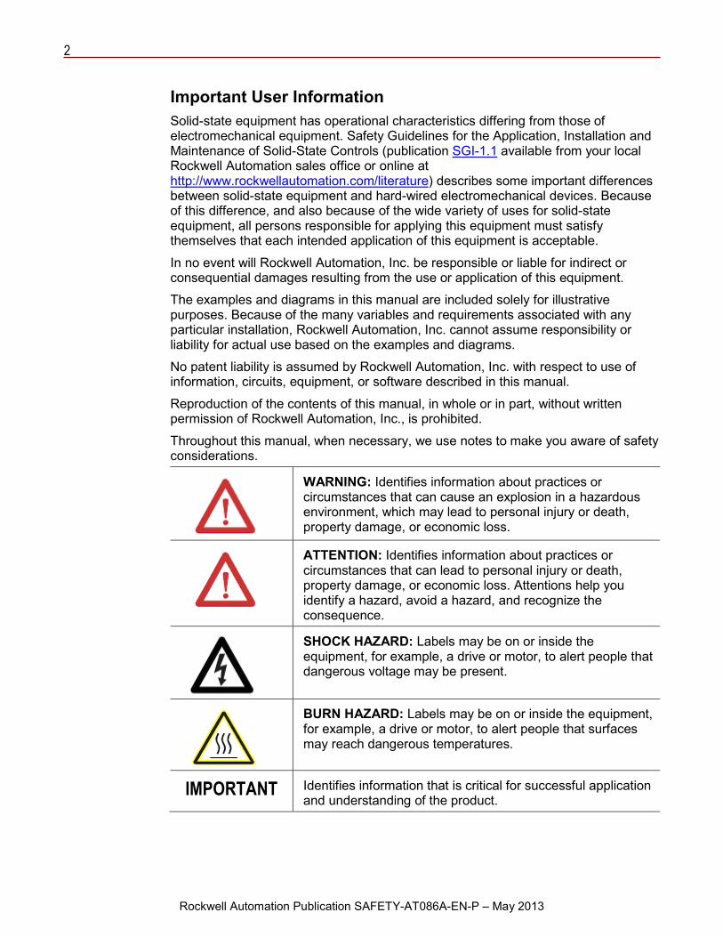
WARNING: Identifies information about practices or circumstances that can cause an explosion in a hazardous environment, which may lead to personal injury or death, property damage, or economic loss.
ATTENTION: Identifies information about practices or circumstances that can lead to personal injury or death, property damage, or economic loss. Attentions help you identify a hazard, avoid a hazard, and recognize the consequence.
SHOCK HAZARD: Labels may be on or inside the equipment, for example, a drive or motor, to alert people that dangerous voltage may be present.
BURN HAZARD: Labels may be on or inside the equipment, for example, a drive or motor, to alert people that surfaces may reach dangerous temperatures.
IMPORTANT Identifies information that is critical for successful application and understanding of the product.
3
Rockwell Automation Publication SAFETY-AT086A-EN-P – May 2013
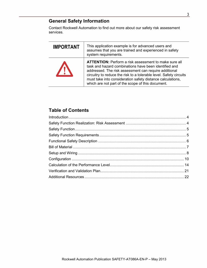
General Safety Information Contact Rockwell Automation to find out more about our safety risk assessment services.
IMPORTANT This application example is for advanced users and assumes that you are trained and experienced in safety system requirements.
ATTENTION: Perform a risk assessment to make sure all task and hazard combinations have been identified and addressed. The risk assessment can require additional circuitry to reduce the risk to a tolerable level. Safety circuits must take into consideration safety distance calculations, which are not part of the scope of this document.
Table of Contents Introduction ............................................................................................................... 4 Safety Function Realization: Risk Assessment ......................................................... 4 Safety Function ......................................................................................................... 5 Safety Function Requirements .................................................................................. 5 Functional Safety Description ................................................................................... 6 Bill of Material ........................................................................................................... 7 Setup and Wiring ...................................................................................................... 8 Configuration .......................................................................................................... 10 Calculation of the Performance Level ...................................................................... 14 Verification and Validation Plan ............................................................................... 21 Additional Resources .............................................................................................. 22
4
Rockwell Automation Publication SAFETY-AT086A-EN-P – May 2013
Introduction This safety function application technique explains how to wire, configure, and integrate two 872C proximity sensors, a Guardmaster® Guard Locking with Proximity Sensor Safety Relay (GSR GLP), a TLSZR-GD2 guard locking switch, two E-stops, a Guardmaster Dual Input (GSR DI) safety relay, and a PowerFlex® 70 Drive into a safety system to provide safe, guarded access to a hazardous area only when the hazardous monitored motion is at Safe Limited Speed or slower. Emergency stops are provided whenever the monitored speed exceeds the Safe Maximum Speed or when either of two E-stops is pressed. An emergency stop is also provided when Safe Limited Speed has been requested, the gate is unlocked and open, and the monitored hazardous motion increases to exceed the configured Safe Limited Speed. The GSR GLP relay monitors the 872C sensors and the TLSZR GD2 switch for faults in their state and sequence of operation. The GSR DI relay monitors the E-stops and the Safe-Off function of the PowerFlex 70 drive for faults in their operational state or their circuits. The GSR GLP and GSR DI relays monitor their internal circuits for faults. Faults do not lead to the system failing to perform its safety function on demand, which is de-energizing the hazardous motion. Once the safety function has been performed, the system cannot be reset until the fault has been corrected.
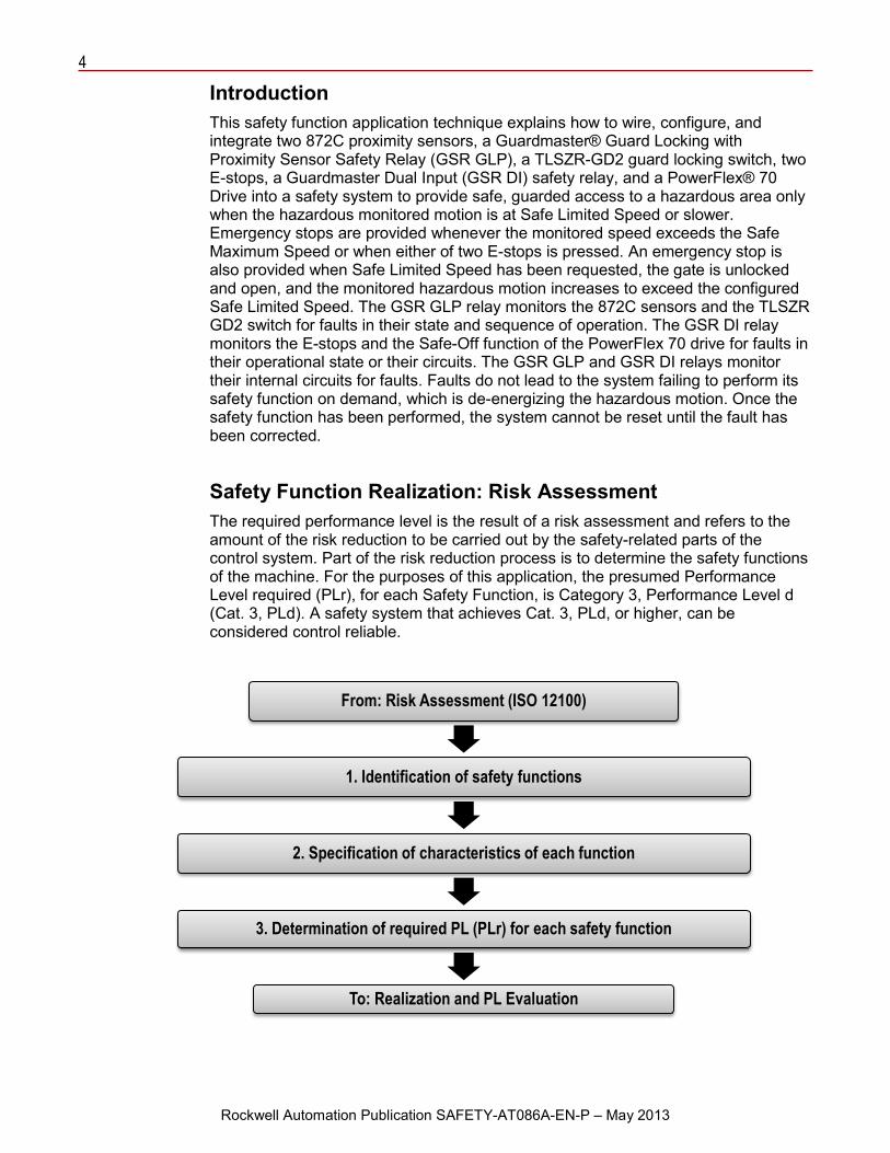
Safety Function Realization: Risk Assessment The required performance level is the result of a risk assessment and refers to the amount of the risk reduction to be carried out by the safety-related parts of the control system. Part of the risk reduction process is to determine the safety functions of the machine. For the purposes of this application, the presumed Performance Level required (PLr), for each Safety Function, is Category 3, Performance Level d (Cat. 3, PLd). A safety system that achieves Cat. 3, PLd, or higher, can be considered control reliable.
From: Risk Assessment (ISO 12100)
1. Identification of safety functions
2. Specification of characteristics of each function
3. Determination of required PL (PLr) for each safety function
To: Realization and PL Evaluation
5
Rockwell Automation Publication SAFETY-AT086A-EN-P – May 2013
Safety Function This application includes four safety functions.
1. Removal of power from the hazardous motion when either E-stop 1 or E-stop 2 is pressed.
2. Removal of power from the hazardous motion when the monitored hazardous motion exceeds the Safe Maximum Speed.
3. Removal of power from the hazardous motion when the gate is open and the monitored hazardous motion exceeds the Safe Limited Speed.
4. Prevention of access to the hazardous area when hazardous motion is present.
This system provides a Stop category 0 stop; power is removed and hazardous motion coasts to a stop.
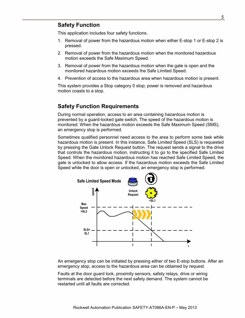
Safety Function Requirements During normal operation, access to an area containing hazardous motion is prevented by a guard-locked gate switch. The speed of the hazardous motion is monitored. When the hazardous motion exceeds the Safe Maximum Speed (SMS), an emergency stop is performed.
Sometimes qualified personnel need access to the area to perform some task while hazardous motion is present. In this instance, Safe Limited Speed (SLS) is requested by pressing the Gate Unlock Request button. The request sends a signal to the drive that controls the hazardous motion, instructing it to go to the specified Safe Limited Speed. When the monitored hazardous motion has reached Safe Limited Speed, the gate is unlocked to allow access. If the hazardous motion exceeds the Safe Limited Speed while the door is open or unlocked, an emergency stop is performed.
An emergency stop can be initiated by pressing either of two E-stop buttons. After an emergency stop, access to the hazardous area can be obtained by request.
Faults at the door guard lock, proximity sensors, safety relays, drive or wiring terminals are detected before the next safety demand. The system cannot be restarted until all faults are corrected.
Safe Limited Speed Mode
Max Speed =SL2
SLS=SL1
Unlock Request
<SL1
t
spee
d
6
Rockwell Automation Publication SAFETY-AT086A-EN-P – May 2013
The safety function meets the requirements for Category 3, Performance Level d (Cat. 3, PLd), per ISO 13849-1, and SIL3 per IEC 62061, and control reliable operation per ANSI B11.19.
Functional Safety Description In this application example, the access gate is locked during normal operation. Two inductive proximity sensors are mounted to detect the presence of ‘Mark’ and ‘Space’ features on a specifically designed ‘target wheel’. Mount the ‘target wheel’ as close as possible to the relevant hazardous moving parts. The Guardmaster Safety Relay (GSR) GLP monitors the two proximity sensors and the output signal switching device (OSSD) outputs of the TLSZR-GD2 guard locking switch. The TLSZ-GD2 switch monitors itself for internal faults, lock status and gate actuation. When a fault is detected, with the gate unlocked and/or open, the TLSZR-GD2 switch turns off both of its OSSD outputs. When the signals from the proximity sensors indicate speed in excess of the Safe Maximum Speed (1200 RPM/200 Hz in this example), speed in excess of Safe Limited Speed (30 RPM/5 Hz in this example) with the gate open or unlocked, or incorrect proximity sensor operation, the GSR GLP relay sends the GSR DI relay an emergency stop signal via the L11-to-L12 Single Wire Safety connection. The GSR DI responds by opening its safety contacts, which turns off the enable and gate control power via the Safe-Off feature of the drive. Hazardous motion coasts to a stop (Stop Category 0).
The GSR DI relay uses pulse testing to monitor the E-stop buttons for status and faults. When an E-stop button is pressed, the GSR DI relay responds by opening its safety contacts, which turns off the enable and gate control power of the drive. Hazardous motion coasts to a stop (Stop Category 0). A fault, depending on type, causes an immediate emergency stop and/or prevents system restart after the next demand upon the safety system until the fault is corrected.
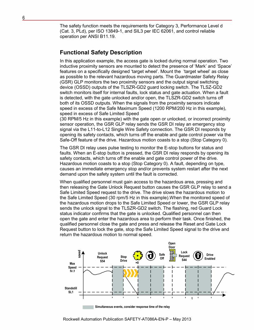
When qualified personnel must gain access to the hazardous area, pressing and then releasing the Gate Unlock Request button causes the GSR GLP relay to send a Safe Limited Speed request to the drive. The drive slows the hazardous motion to the Safe Limited Speed (30 rpm/5 Hz in this example).When the monitored speed of the hazardous motion drops to the Safe Limited Speed or lower, the GSR GLP relay sends the unlock signal to the TLSZR-GD2 switch. The flashing, red Guard Lock status indicator confirms that the gate is unlocked. Qualified personnel can then open the gate and enter the hazardous area to perform their task. Once finished, the qualified personnel close the gate and press and release the Reset and Gate Lock Request button to lock the gate, stop the Safe Limited Speed signal to the drive and return the hazardous motion to normal speed.
Unlock Request
S54 Stop Drive
Safe Off
Lock Request
S44 Drive
Enabled Max
Speed SL2
Standstill SL1
Simultaneous events, consider response time of the relay
spee
d
t
=0
Open Door
7
Rockwell Automation Publication SAFETY-AT086A-EN-P – May 2013
Following a standard, non-emergency stop, access to the hazardous area must be requested by pressing and releasing the Gate Unlock Request button. The gate is not unlocked unless any hazardous motion remaining is at Safe Limited Speed or less.
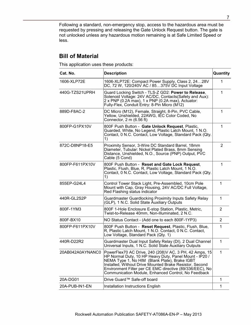
Bill of Material This application uses these products:
Cat. No. Description Quantity
1606-XLP72E 1606-XLP72E: Compact Power Supply, Class 2, 24…28V DC, 72 W, 120/240V AC / 85…375V DC Input Voltage
1
440G-TZS21UPRH Guard Locking Switch - TLS-Z GD2: Power to Release, Solenoid Voltage: 24V AC/DC, Contacts(Safety and Aux): 2 x PNP (0.2A max), 1 x PNP (0.2A max), Actuator: Fully-Flex, Conduit Entry: 8-Pin Micro (M12)
1
889D-F8AC-2 DC Micro (M12), Female, Straight, 8-Pin, PVC Cable, Yellow, Unshielded, 22AWG, IEC Color Coded, No Connector, 2 m (6.56 ft)
1
800FP-G1PX10V 800F Push Button - Gate Unlock Request, Plastic, Guarded, White, No Legend, Plastic Latch Mount, 1 N.O. Contact, 0 N.C. Contact, Low Voltage, Standard Pack (Qty. 1)
1
872C-D8NP18-E5 Proximity Sensor, 3-Wire DC Standard Barrel, 18mm Diameter, Tubular: Nickel Plated Brass, 8mm Sensing Distance, Unshielded, N.O., Source (PNP) Output, PVC Cable (5 Cond)
2
800FP-F611PX10V 800F Push Button - Reset and Gate Lock Request, Plastic, Flush, Blue, R, Plastic Latch Mount, 1 N.O. Contact, 0 N.C. Contact, Low Voltage, Standard Pack (Qty. 1)
1
855EP-G24L4 Control Tower Stack Light, Pre-Assembled, 10cm Pole Mount with Cap, Gray Housing, 24V AC/DC Full Voltage, Red Flashing status indicator
1
440R-GL2S2P Guardmaster Guardlocking Proximity Inputs Safety Relay (GLP), 1 N.C. Solid State Auxiliary Outputs
1
800F-1YM3 800F 1-Hole Enclosure E-stop Station, Plastic, Metric, Twist-to-Release 40mm, Non-Illuminated, 2 N.C.
2
800F-BX10 NO Status Contact - (Add one to each 800F-1YP3) 2 800FP-F611PX10V 800F Push Button - Reset Request, Plastic, Flush, Blue,
R, Plastic Latch Mount, 1 N.O. Contact, 0 N.C. Contact, Low Voltage, Standard Pack (Qty. 1)
1
440R-D22R2 Guardmaster Dual Input Safety Relay (DI), 2 Dual Channel Universal Inputs, 1 N.C. Solid State Auxiliary Outputs
1
20AB042A0AYNANC0 PowerFlex70 AC Drive, 240 (208)V AC, 3 PH, 42 Amps, 15 HP Normal Duty, 10 HP Heavy Duty, Panel Mount - IP20 / NEMA Type 1, No HIM (Blank Plate), Brake IGBT Installed, Without Drive Mounted Brake Resistor, Second Environment Filter per CE EMC directive (89/336/EEC), No Communication Module, Enhanced Control, No Feedback
1
20A-DG01 Drive Guard™ Safe-off board 1 20A-PUB-IN1-EN Installation Instructions English 1
8
Rockwell Automation Publication SAFETY-AT086A-EN-P – May 2013
Setup and Wiring For detailed information on installing and wiring, refer to the publications listed in the Additional Resources on the back cover.
System Overview The Guardmaster Guard Locking with Proximity Sensor Safety Relay (GSR GLP) monitors the two proximity sensors and the TLSZR-GD2 switch. The GSR GLP relay monitors and provides the DC supply to the sensors and confirms that their output’s frequency of operation and sequence of operation are proper. Only one sensor’s output can be OFF at any given time. Having both the sensor outputs OFF at the same time is a fault; the GSR GLP relay initiates an emergency stop in response. The GSR GLP relay monitors the state of the two OSSD outputs from the TLSZR-GD2 switch. Both must be in the same state, either both ON or both OFF. The GSR GLP relay initiates an emergency stop in response to any other instance.
The TLSZR-GD2 switch monitors the state of the lock, the presence of the ‘tongue’ and its internal circuits for faults. The TLSZR-GD2 switch responds to any discrepancies by turning both of its OSSD outputs OFF.
The GSR GLP relay monitors its own internal circuitry. If a fault occurs, the GSR GLP relay sends an emergency stop signal to the GSR DI via the Single Wire Safety connection. The GSR DI responds by opening its safety contacts, shutting OFF the drive.
The GSR DI monitors the E-stop by running its S11 and S21 pulsed outputs through the two channels of the E-stop to inputs S12 and S22, respectively. A loose wire, a shorted contact, a short to 24V, a short to 0V or a cross-fault between the channels is detected by the GSR DI relay. It also monitors the Single Wire Safety Input from the GSR GLP relay.
The GSR DI, monitoring both the E-stops and the TLSZR-GD2 switch outputs, responds to any faults or demands from the devices by de-energizing its safety contacts, removing the enable signal to the drive, and removing the gate control circuit power supply from the gate control circuit. Hazardous motion coasts to a stop (Stop Category 0).
The PowerFlex 70 drive monitors its inputs and internal circuitry for proper operation. When a fault is detected, the drive responds by turning its output OFF. Hazardous motion coasts to a stop (Stop Category 0).
9
Rockwell Automation Publication SAFETY-AT086A-EN-P – May 2013
Electrical Schematic
TLS-Z GD2
889D-F8AC-2
Guard Lock Status Indicator White (Aux) Brown
Red Yellow Blue
Green (Unlock)
Pink (OSSD2) Gray (ODDS1)
Gate Unlock Request
(Safe Limited Speed Request) Status To PLC Reset &
Gate Lock Request Brown Black
Blue
Brown Black
Blue
PowerFlex 70 with DriveGuard
1 Stop 2 Stop 9 24V DC
3 Speed Select 1
Safety Status to PLC
Reset Request
Remove Jumper
6 Enable Gate Control Circuit
Gate Control Power Supply
7 DC Comm 8 Digital In Com
*Class 2 Power Source
+24V DC* 24V DC COM
Status To PLC
E-stop 1 Status To PLC
E-stop 2 Status To PLC
10
Rockwell Automation Publication SAFETY-AT086A-EN-P – May 2013
Configuration
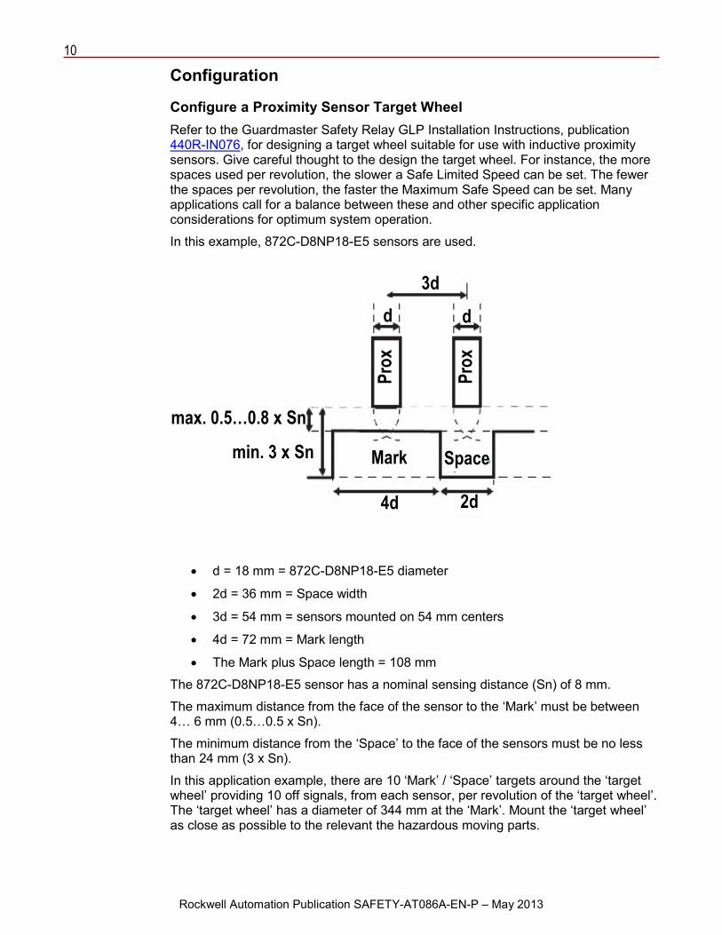
Configure a Proximity Sensor Target Wheel Refer to the Guardmaster Safety Relay GLP Installation Instructions, publication 440R-IN076, for designing a target wheel suitable for use with inductive proximity sensors. Give careful thought to the design the target wheel. For instance, the more spaces used per revolution, the slower a Safe Limited Speed can be set. The fewer the spaces per revolution, the faster the Maximum Safe Speed can be set. Many applications call for a balance between these and other specific application considerations for optimum system operation.
In this example, 872C-D8NP18-E5 sensors are used.
• d = 18 mm = 872C-D8NP18-E5 diameter
• 2d = 36 mm = Space width
• 3d = 54 mm = sensors mounted on 54 mm centers
• 4d = 72 mm = Mark length
• The Mark plus Space length = 108 mm
The 872C-D8NP18-E5 sensor has a nominal sensing distance (Sn) of 8 mm.
The maximum distance from the face of the sensor to the ‘Mark’ must be between 4… 6 mm (0.5…0.5 x Sn).
The minimum distance from the ‘Space’ to the face of the sensors must be no less than 24 mm (3 x Sn).
In this application example, there are 10 ‘Mark’ / ‘Space’ targets around the ‘target wheel’ providing 10 off signals, from each sensor, per revolution of the ‘target wheel’. The ‘target wheel’ has a diameter of 344 mm at the ‘Mark’. Mount the ‘target wheel’ as close as possible to the relevant the hazardous moving parts.
max. 0.5…0.8 x Sn
min. 3 x Sn
3d d d
Mark Space
4d 2d
Prox
Prox
11
Rockwell Automation Publication SAFETY-AT086A-EN-P – May 2013
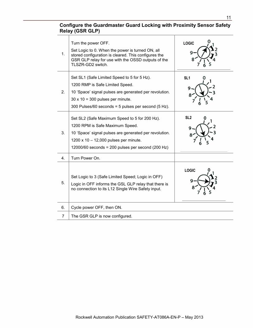
Configure the Guardmaster Guard Locking with Proximity Sensor Safety Relay (GSR GLP)
1.
Turn the power OFF.
Set Logic to 0. When the power is turned ON, all stored configuration is cleared. This configures the GSR GLP relay for use with the OSSD outputs of the TLSZR-GD2 switch.
2.
Set SL1 (Safe Limited Speed to 5 for 5 Hz).
1200 RMP is Safe Limited Speed.
10 ‘Space’ signal pulses are generated per revolution.
30 x 10 = 300 pulses per minute.
300 Pulses/60 seconds = 5 pulses per second (5 Hz).
3.
Set SL2 (Safe Maximum Speed to 5 for 200 Hz).
1200 RPM is Safe Maximum Speed.
10 ‘Space’ signal pulses are generated per revolution.
1200 x 10 – 12,000 pulses per minute.
12000/60 seconds = 200 pulses per second (200 Hz)
4. Turn Power On.
5. Set Logic to 3 (Safe Limited Speed; Logic in OFF)
Logic in OFF informs the GSL GLP relay that there is no connection to its L12 Single Wire Safety input.
6. Cycle power OFF, then ON.
7 The GSR GLP is now configured.
LOGIC
SL2
SL1
LOGIC
12
Rockwell Automation Publication SAFETY-AT086A-EN-P – May 2013
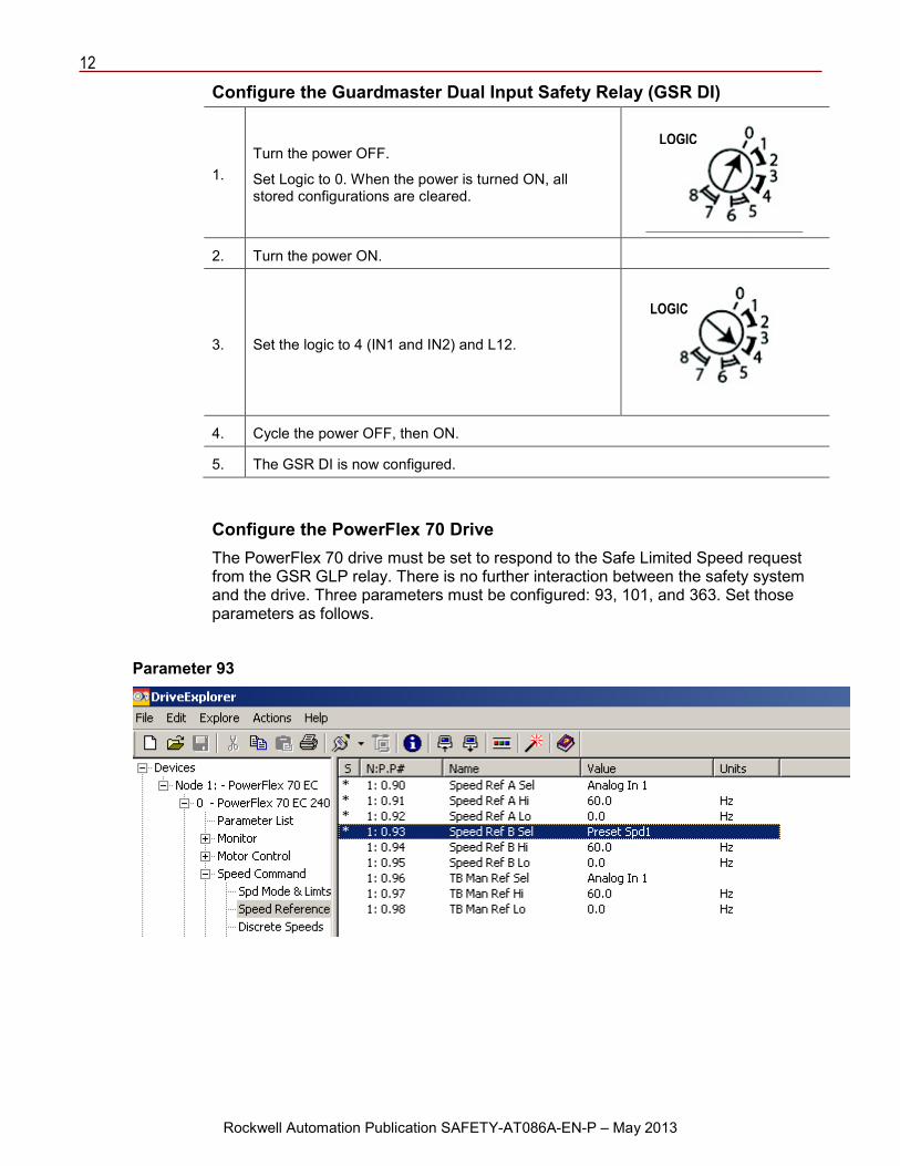
Configure the Guardmaster Dual Input Safety Relay (GSR DI)
1. Turn the power OFF.
Set Logic to 0. When the power is turned ON, all stored configurations are cleared.
2. Turn the power ON.
3. Set the logic to 4 (IN1 and IN2) and L12.
4. Cycle the power OFF, then ON.
5. The GSR DI is now configured.
Configure the PowerFlex 70 Drive The PowerFlex 70 drive must be set to respond to the Safe Limited Speed request from the GSR GLP relay. There is no further interaction between the safety system and the drive. Three parameters must be configured: 93, 101, and 363. Set those parameters as follows.
Parameter 93
LOGIC
LOGIC
13
Rockwell Automation Publication SAFETY-AT086A-EN-P – May 2013
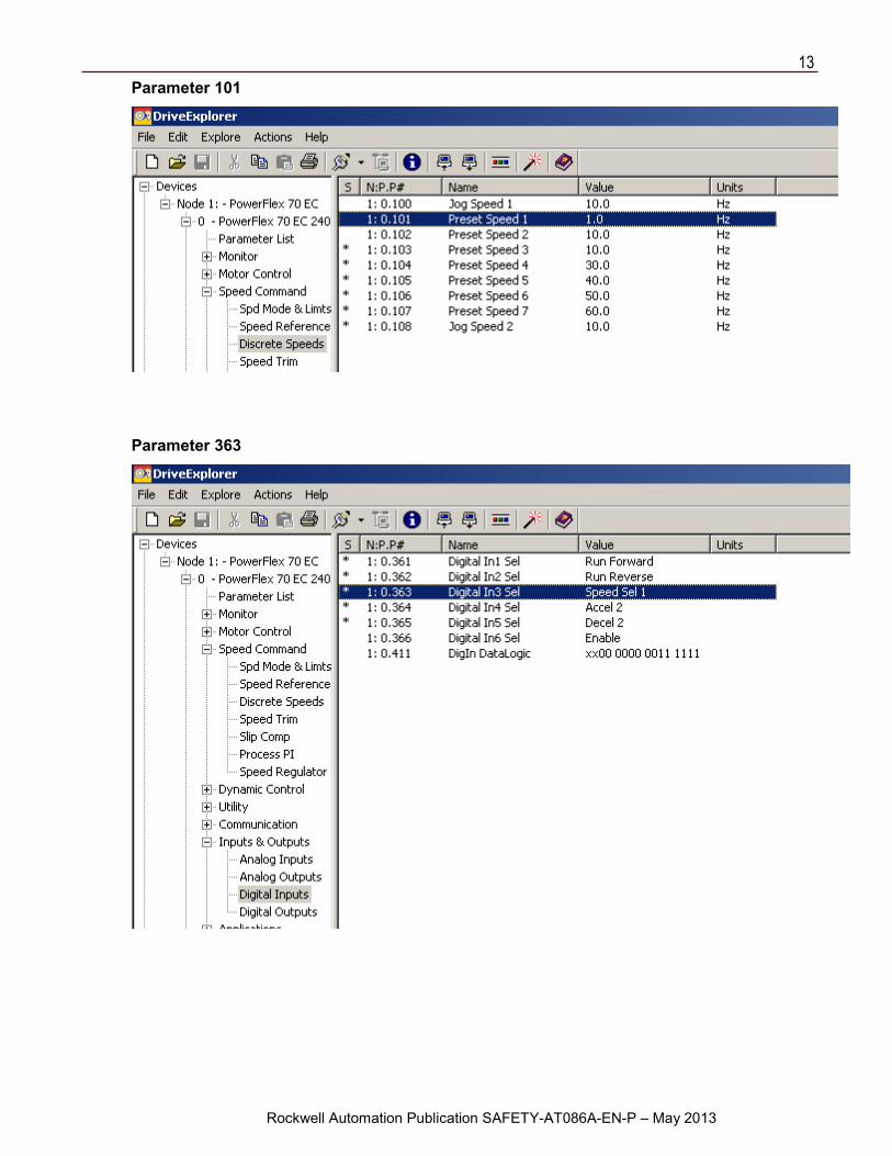
Parameter 101
Parameter 363
14
Rockwell Automation Publication SAFETY-AT086A-EN-P – May 2013
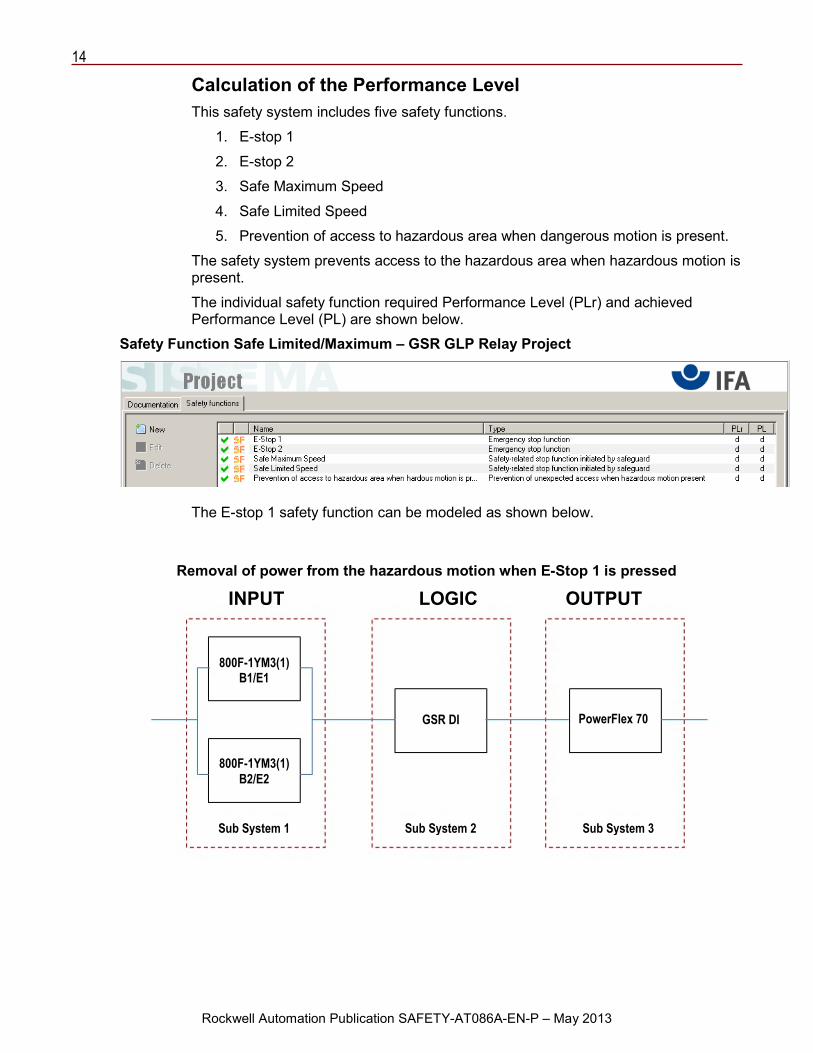
Calculation of the Performance Level This safety system includes five safety functions.
1. E-stop 1
2. E-stop 2
3. Safe Maximum Speed
4. Safe Limited Speed
5. Prevention of access to hazardous area when dangerous motion is present.
The safety system prevents access to the hazardous area when hazardous motion is present.
The individual safety function required Performance Level (PLr) and achieved Performance Level (PL) are shown below.
Safety Function Safe Limited/Maximum – GSR GLP Relay Project
The E-stop 1 safety function can be modeled as shown below.
Removal of power from the hazardous motion when E-Stop 1 is pressed
INPUT LOGIC OUTPUT
800F-1YM3(1) B1/E1
800F-1YM3(1) B2/E2
PowerFlex 70 GSR DI
Sub System 1 Sub System 2 Sub System 3
15
Rockwell Automation Publication SAFETY-AT086A-EN-P – May 2013
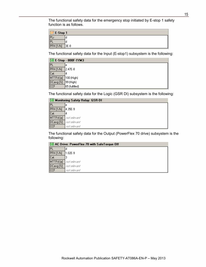
The functional safety data for the emergency stop initiated by E-stop 1 safety function is as follows.
The functional safety data for the Input (E-stop1) subsystem is the following:
The functional safety data for the Logic (GSR DI) subsystem is the following:
The functional safety data for the Output (PowerFlex 70 drive) subsystem is the following:
16
Rockwell Automation Publication SAFETY-AT086A-EN-P – May 2013
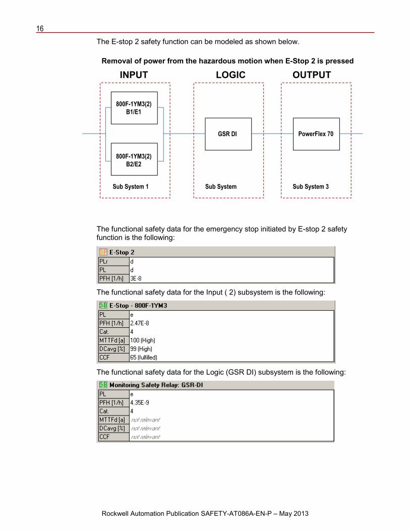
The E-stop 2 safety function can be modeled as shown below.
The functional safety data for the emergency stop initiated by E-stop 2 safety function is the following:
The functional safety data for the Input ( 2) subsystem is the following:
The functional safety data for the Logic (GSR DI) subsystem is the following:
Removal of power from the hazardous motion when E-Stop 2 is pressed
INPUT LOGIC OUTPUT
800F-1YM3(2) B1/E1
800F-1YM3(2) B2/E2
GSR DI PowerFlex 70
Sub System 1 Sub System
Sub System 3
17
Rockwell Automation Publication SAFETY-AT086A-EN-P – May 2013
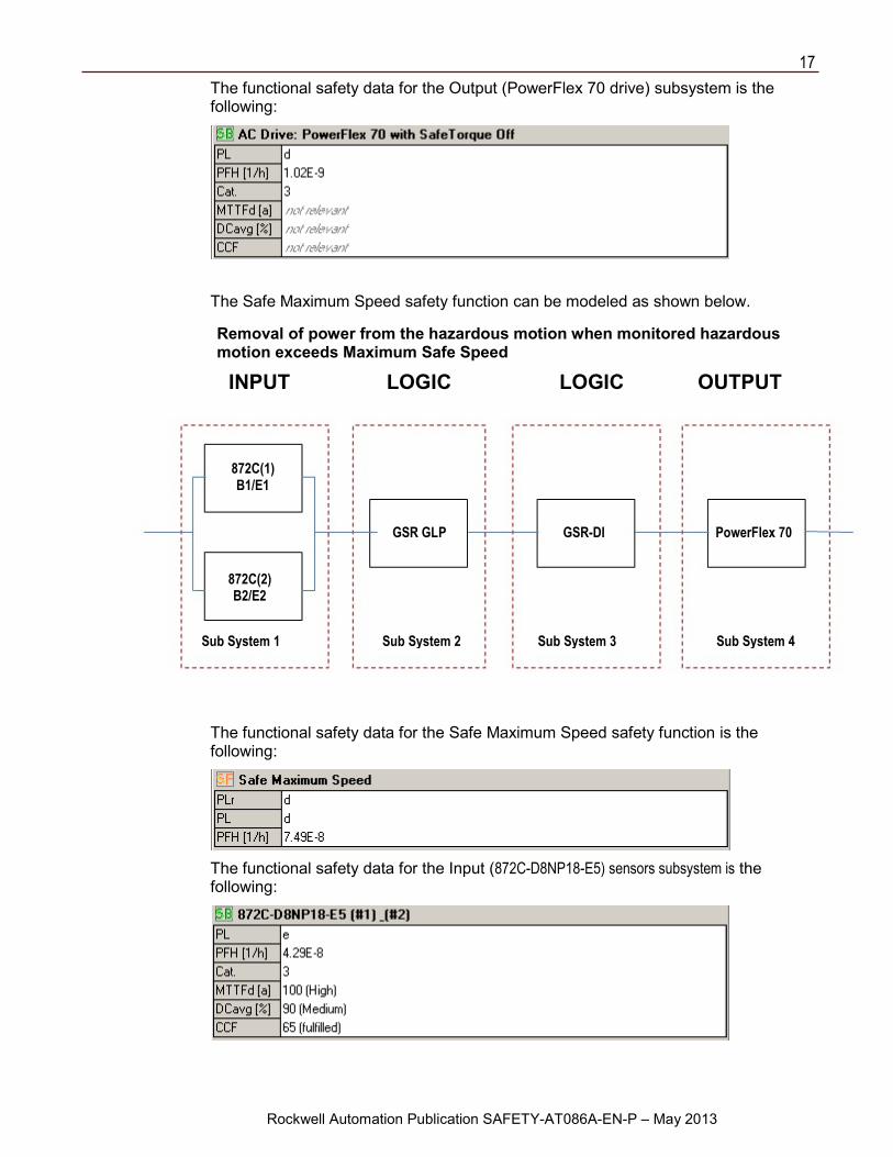
The functional safety data for the Output (PowerFlex 70 drive) subsystem is the following:
The Safe Maximum Speed safety function can be modeled as shown below.
The functional safety data for the Safe Maximum Speed safety function is the following:
The functional safety data for the Input (872C-D8NP18-E5) sensors subsystem is the following:
Removal of power from the hazardous motion when monitored hazardous motion exceeds Maximum Safe Speed
INPUT LOGIC LOGIC OUTPUT
872C(1) B1/E1
872C(2) B2/E2
GSR GLP GSR-DI PowerFlex 70
Sub System 1 Sub System 2 Sub System 3 Sub System 4
18
Rockwell Automation Publication SAFETY-AT086A-EN-P – May 2013
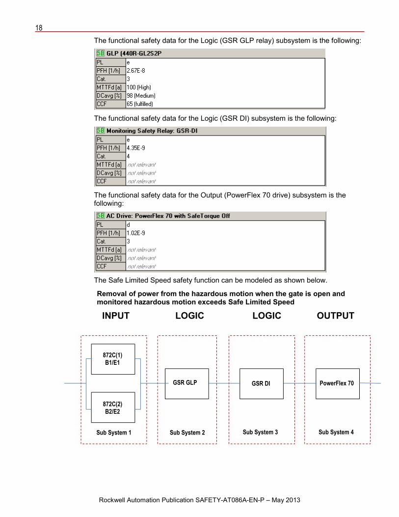
The functional safety data for the Logic (GSR GLP relay) subsystem is the following:
The functional safety data for the Logic (GSR DI) subsystem is the following:
The functional safety data for the Output (PowerFlex 70 drive) subsystem is the following:
The Safe Limited Speed safety function can be modeled as shown below.
Removal of power from the hazardous motion when the gate is open and monitored hazardous motion exceeds Safe Limited Speed
INPUT LOGIC LOGIC OUTPUT
872C(1) B1/E1
872C(2) B2/E2
GSR GLP GSR DI PowerFlex 70
Sub System 1 Sub System 2 Sub System 3 Sub System 4
19
Rockwell Automation Publication SAFETY-AT086A-EN-P – May 2013
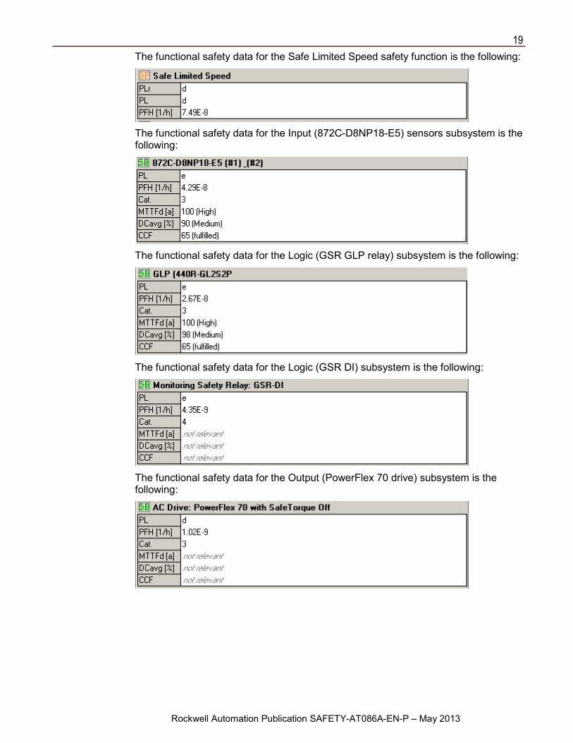
The functional safety data for the Safe Limited Speed safety function is the following:
The functional safety data for the Input (872C-D8NP18-E5) sensors subsystem is the following:
The functional safety data for the Logic (GSR GLP relay) subsystem is the following:
The functional safety data for the Logic (GSR DI) subsystem is the following:
The functional safety data for the Output (PowerFlex 70 drive) subsystem is the following:
20
Rockwell Automation Publication SAFETY-AT086A-EN-P – May 2013
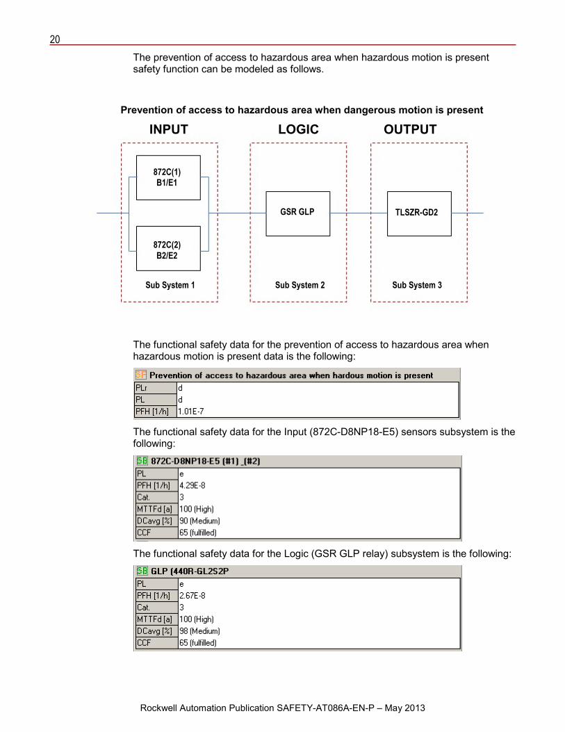
The prevention of access to hazardous area when hazardous motion is present safety function can be modeled as follows.
The functional safety data for the prevention of access to hazardous area when hazardous motion is present data is the following:
The functional safety data for the Input (872C-D8NP18-E5) sensors subsystem is the following:
The functional safety data for the Logic (GSR GLP relay) subsystem is the following:
Prevention of access to hazardous area when dangerous motion is present
INPUT LOGIC OUTPUT
872C(1) B1/E1
872C(2) B2/E2
GSR GLP TLSZR-GD2
Sub System 1 Sub System 2 Sub System 3
21
Rockwell Automation Publication SAFETY-AT086A-EN-P – May 2013
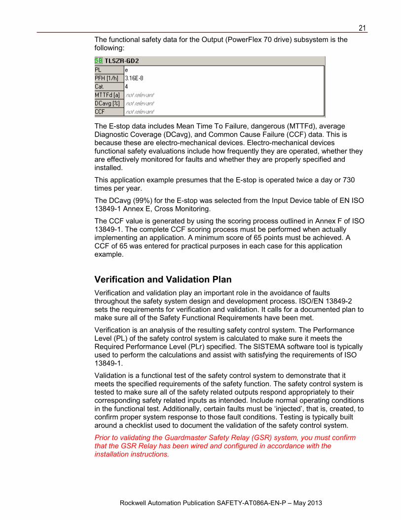
The functional safety data for the Output (PowerFlex 70 drive) subsystem is the following:
The E-stop data includes Mean Time To Failure, dangerous (MTTFd), average Diagnostic Coverage (DCavg), and Common Cause Failure (CCF) data. This is because these are electro-mechanical devices. Electro-mechanical devices functional safety evaluations include how frequently they are operated, whether they are effectively monitored for faults and whether they are properly specified and installed.
This application example presumes that the E-stop is operated twice a day or 730 times per year.
The DCavg (99%) for the E-stop was selected from the Input Device table of EN ISO 13849-1 Annex E, Cross Monitoring.
The CCF value is generated by using the scoring process outlined in Annex F of ISO 13849-1. The complete CCF scoring process must be performed when actually implementing an application. A minimum score of 65 points must be achieved. A CCF of 65 was entered for practical purposes in each case for this application example.
Verification and Validation Plan Verification and validation play an important role in the avoidance of faults throughout the safety system design and development process. ISO/EN 13849-2 sets the requirements for verification and validation. It calls for a documented plan to make sure all of the Safety Functional Requirements have been met.
Verification is an analysis of the resulting safety control system. The Performance Level (PL) of the safety control system is calculated to make sure it meets the Required Performance Level (PLr) specified. The SISTEMA software tool is typically used to perform the calculations and assist with satisfying the requirements of ISO 13849-1.
Validation is a functional test of the safety control system to demonstrate that it meets the specified requirements of the safety function. The safety control system is tested to make sure all of the safety related outputs respond appropriately to their corresponding safety related inputs as intended. Include normal operating conditions in the functional test. Additionally, certain faults must be ‘injected’, that is, created, to confirm proper system response to those fault conditions. Testing is typically built around a checklist used to document the validation of the safety control system.
Prior to validating the Guardmaster Safety Relay (GSR) system, you must confirm that the GSR Relay has been wired and configured in accordance with the installation instructions.
22
Rockwell Automation Publication SAFETY-AT086A-EN-P – May 2013
Additional Resources For more information about the products used in this application refer to these resources.
Resource Description
Switched Mode & Uninterruptible Power Supplies, publication 1606-BR001
Provides information regarding the available power supplies.
Guard Locking Switches TLS-Z GD2, publication S118-CA500
Provides specifications for the Guard Locking Switches.
TLS-Z GD2 Safety Guard Locking Switches, publication 440GZ-PP001
Provides information regarding the TLS-GD2 family of Guard Locking Switches.
WorldProx™ 3-Wire DC Proximity Sensors, publication 872C-PP003
Provides information and specifications for sensing applications.
Inductive Proximity Sensors Catalog, publication C116-CA502
Provides information and specifications regarding Inductive Proximity Sensors.
Guardmaster Guard Locking with Proximity Sensors Safety Relay, publication 440RG-PP001
Provides information and specifications on the Guard Locking Relay.
Guardmaster Safety Relay GLP Installation Instructions, publication 440R-IN076
Provides installation instructions on the Safety Relay GLP.
Guardmaster Safety Relay GLP Quick Start Guide, publication 440R-TG004
Provides a troubleshooting guide for the Safety Relay GLP.
Guardmaster Safety Relay DI Installation Instructions, publication 440R-IN037
Provides installation instructions on the Safety Relay DI.
Guardmaster Safety Relay DI/DIS Quick Start Guide, publication 440R-TG002
Provides a troubleshooting guide for the Safety Relay DI/DIS.
GSR - Guardmaster Safety Relays Safety Applications and Wiring Diagrams, publication SAFETY-WD001
Provides safety applications and wiring diagrams for the Guardmaster Safety Relays.
Next Generation Guardmaster Safety Relays, publication EUSAFE-BR009
Provides information and specifications for the Next Generation Safety Relays.
23
For More Information on Safety Function Capabilities, visit: discover.rockwellautomation.com/safety Rockwell Automation, Allen-Bradley, Rockwell Software, LISTEN.THINK.SOLVE, Guardmaster, PowerFlex, WorldProx, and DriveGuard are trademarks of Rockwell Automation, Inc. Trademarks not belonging to Rockwell Automation are property of their respective companies.
Publication SAFETY-AT086A-EN-P – May 2013 Copyright © 2013 Rockwell Automation, Inc. All rights reserved. Printed in U.SA
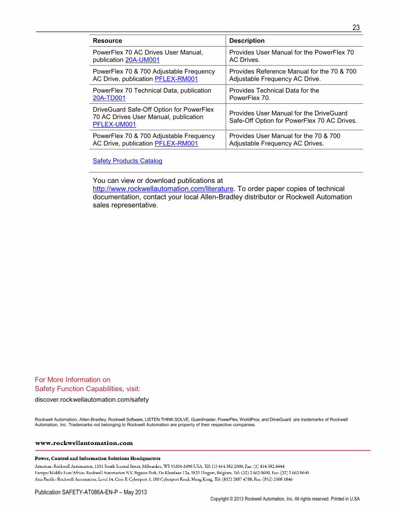
Resource Description
PowerFlex 70 AC Drives User Manual, publication 20A-UM001
Provides User Manual for the PowerFlex 70 AC Drives.
PowerFlex 70 & 700 Adjustable Frequency AC Drive, publication PFLEX-RM001
Provides Reference Manual for the 70 & 700 Adjustable Frequency AC Drive.
PowerFlex 70 Technical Data, publication 20A-TD001
Provides Technical Data for the PowerFlex 70.
DriveGuard Safe-Off Option for PowerFlex 70 AC Drives User Manual, publication PFLEX-UM001
Provides User Manual for the DriveGuard Safe-Off Option for PowerFlex 70 AC Drives.
PowerFlex 70 & 700 Adjustable Frequency AC Drive, publication PFLEX-RM001
Provides User Manual for the 70 & 700 Adjustable Frequency AC Drives.
Safety Products Catalog
You can view or download publications at http://www.rockwellautomation.com/literature. To order paper copies of technical documentation, contact your local Allen-Bradley distributor or Rockwell Automation sales representative.