GRL-PCIE3-RXMOIandUserGuide Rev.1.2.0©GraniteRiverLabs2016 Page1of87
GRLPCIeBaseGen3MOIforTektronix8GbpsPhysicalLayerTestSuite

GRL-PCIE3-RXMOIandUserGuide Rev.1.2.0©GraniteRiverLabs2016 Page2of87
TABLEOFCONTENTS
1 INTRODUCTION 92 REFERENCEDOCUMENTS 93 RESOURCEREQUIREMENTS 103.1 EQUIPMENTREQUIREMENTS....................................................................................................................103.2 SOFTWAREREQUIREMENTS......................................................................................................................10
4 CALIBRATION 114.1 CALIBRATIONPROCESSCONNECTIONSETUPS........................................................................................114.1.1 CalibrationforTP1.......................................................................................................................114.1.2 CalibrationforTP2.......................................................................................................................12
5 SOFTWARE 125.1 SETUP............................................................................................................................................................125.1.1 LaunchandSetupSoftware......................................................................................................135.1.2 AdditionalNotes............................................................................................................................19
5.2 CALIBRATINGUSINGTHESOFTWARE.......................................................................................................195.2.1 SessionInfo......................................................................................................................................195.2.2 ConditionsforTestingandCalibration................................................................................205.2.3 SetupConfiguration.....................................................................................................................205.2.4 SelectingCalibrationStepsUsingtheSoftware...............................................................245.2.5 RunCalibrationSteps..................................................................................................................24
5.3 TESTINGUSINGGRL-PCIE3-BASE-RXSOFTWARE............................................................................255.3.1 ReceiverComplianceTests.......................................................................................................255.3.2 ReceiverMarginTests.................................................................................................................25
5.4 REPORT.........................................................................................................................................................255.5 INTERPRETINGAREPORT..........................................................................................................................265.5.1 DUTInformation............................................................................................................................265.5.2 SummaryTable..............................................................................................................................275.5.3 CalibrationDataResults.............................................................................................................285.5.4 ComplianceTestResults............................................................................................................295.5.5 JitterMarginResults....................................................................................................................30
6 TESTSUITE 307 APPENDIXA:ARTEKCLE1000-A2INSTALLATION 307.1 ISIGENERATORDRIVERINSTALLATION..................................................................................................307.2 CLE1000GUIINSTALLATION.................................................................................................................33
8 APPENDIX B: BERT SCOPEISITRACEBOARD 34

GRL-PCIE3-RXMOIandUserGuide Rev.1.2.0©GraniteRiverLabs2016 Page3of87
9 APPENDIXC:MANUALTESTMETHODS 359.1 WAVEFORMTESTS......................................................................................................................................359.1.1 PreshootandDeemphasis.........................................................................................................359.1.2 LaunchAmplitude.........................................................................................................................409.1.3 AmplitudeEqualization..............................................................................................................409.1.4 RJCalibration..................................................................................................................................419.1.5 SJCalibration...................................................................................................................................45
9.2 CHANNELCALIBRATIONTESTS(TP2)....................................................................................................499.2.1 ChannelCalibrationInsertionLoss.......................................................................................499.2.2 ChannelCalibrationDifferentialModeSinusoidalInterference...............................569.2.3 ChannelCalibrationACCommonModeSinusoidalInterference.............................58
9.3 CALIBRATIONATTP2P..............................................................................................................................599.3.1 TP2PStressedVoltageCalibration........................................................................................609.3.2 StressedJitterCalibration(ForLongChannelOnly).....................................................68
9.4 RECEIVERTEST...........................................................................................................................................759.4.1 EquipmentSetup...........................................................................................................................759.4.2 StressedVoltageReceiverTest...............................................................................................769.4.3 StressedJitterReceiverTest(100MHz)..............................................................................79
10 PVTAUTOMATION 8210.1 AVAILABLEPARAMETERS......................................................................................................................8210.2 APPLICABLETESTS.................................................................................................................................8210.3 SETTINGUPPVTVALUESEQUENCES..................................................................................................8310.4 SEARCHALGORITHM..............................................................................................................................8610.4.1 JitterMarginTesting................................................................................................................86
10.5 TESTRESULTS..........................................................................................................................................8610.6 SAVINGANDLOADINGAPVTSESSION................................................................................................87

GRL-PCIE3-RXMOIandUserGuide Rev.1.2.0©GraniteRiverLabs2016 Page4of87
ListofFiguresFigure1.TypicalSetupforTP1Calibration........................................................................................................11Figure2.TypicalSetupforTP2Calibration........................................................................................................12Figure3.RemoteClientWindow.............................................................................................................................13Figure4.GRLAutomatedTestSolutionsinStartMenu.................................................................................14Figure5.RxTestSolutionsinGRLAutomatedTestSolutionsWindow.................................................14Figure6.LicenseDetailsWindow...........................................................................................................................15Figure7.OpenChoiceInstrumentManagerinStartMenu...........................................................................16Figure8.InstrumentListinInstrumentManager............................................................................................17Figure9.EquipmentSetupWindow–View#1.................................................................................................18Figure10.EquipmentSetupWindow–View#2..............................................................................................18Figure11.EquipmentSetupWindow–View#3..............................................................................................19Figure12.SessionInfo.................................................................................................................................................19Figure13.ConditionsforTestingandCalibration...........................................................................................20Figure14.ISIGeneratorSetup..................................................................................................................................20Figure15.CustomSJFrequencies...........................................................................................................................21Figure16.ErrorCounterSetup................................................................................................................................21Figure17.LoopbackModeSetup.............................................................................................................................22Figure18.BERandMaximumErrors....................................................................................................................22Figure19.SeasimSetup...............................................................................................................................................23Figure20.ConnectionSetup......................................................................................................................................23Figure21.SelectCalibrationTestsPage...............................................................................................................24Figure22.ConnectionSetup......................................................................................................................................24Figure23.SelectComplianceTestsPage..............................................................................................................25Figure24.SelectMarginTestsPage.......................................................................................................................25Figure25.ReportResultsPage.................................................................................................................................26Figure26.DUTInformation.......................................................................................................................................26Figure27.SummaryTable..........................................................................................................................................27Figure28.CalibrationResultsExample................................................................................................................28Figure29.CalibrationResultsExample................................................................................................................29Figure30.JitterMarginReportExample.............................................................................................................30Figure31.DeviceManagerWindow......................................................................................................................31Figure32.UpdateDriverWindow..........................................................................................................................31Figure33.WindowsSecurityWindowandConfirmationWindow..........................................................32Figure34.DeviceManagerWindowafterInstallation...................................................................................32Figure35.CLE1000GUI...............................................................................................................................................33Figure36.InsertionLossperTraceLength........................................................................................................34Figure37.InsertionLossConnectionsTable.....................................................................................................34

GRL-PCIE3-RXMOIandUserGuide Rev.1.2.0©GraniteRiverLabs2016 Page5of87
Figure38.BERTScopeSetup......................................................................................................................................35Figure39.ScopeSetupandMeasurement...........................................................................................................36Figure40.Measuredtransitionamplitude(Example825mVpp)..............................................................37Figure41.Measurednon-transitionamplitude(Example254mV).........................................................37Figure42.MeasuredPreshootamplitude(Example622mV).....................................................................38Figure43.BERTScopeSetup#2...............................................................................................................................39Figure44.ScopeSetupandMeasurement#2....................................................................................................39Figure45.AmplitudeEqualizationSetup............................................................................................................40Figure46.BERTScopeJitterSetup..........................................................................................................................41Figure47.BERTScopePatternSetup.....................................................................................................................42Figure48.DPOJETConfigureSetup........................................................................................................................42Figure49.RJDJSetup....................................................................................................................................................43Figure50.ScopeAdvancedSetup............................................................................................................................43Figure51.ScopeRecordLengthSetup..................................................................................................................44Figure52.ScopeWaveformCapture......................................................................................................................44Figure53.BERTScopeRJCapture...........................................................................................................................45Figure54.SweepJitterRangeandMask..............................................................................................................46Figure55.SweepJitterBERTScopeSetupat30KHz.......................................................................................46Figure56.SweepJitterBERTScopeSetupat1MHz-100MHz......................................................................47Figure57.SweepJitterDPOJETMeasurementat1MHz-100MHz............................................................48Figure58.Calibrationat1MHz-100MHz..............................................................................................................48Figure59.SweepJitterDPOJETMeasurementat1MHz-100MHz............................................................48Figure60.ChannelInsertionLossMaskbyChannelType...........................................................................49Figure61.ISISetup........................................................................................................................................................50Figure62ScopeSetup#1............................................................................................................................................50Figure63ScopeSetup#2............................................................................................................................................50Figure64ScopeAcquisitionModeSetup.............................................................................................................51Figure65CaptureMeasurement.............................................................................................................................51Figure66SavetheWaveform...................................................................................................................................52Figure67SeasimInsertionLossOutputGraph.................................................................................................53Figure68SpecificationMask.....................................................................................................................................54Figure69InsertionLossat27.5%ISI(-16.9dB)..............................................................................................54Figure70InsertionLossat30.%ISI(-17.9dB).................................................................................................55Figure71InsertionLossat32.5%ISI(-18.9dB)WithinTarget................................................................55Figure72InsertionLossCalibrationforLongChannel–ILfallsbetweenrequiredmask............56Figure73BERTScopeSetupforALLZEROPattern.........................................................................................56Figure74BERTScopeSetup#2................................................................................................................................57Figure75ArtekISISetup............................................................................................................................................57Figure76ScopeMeasurement.................................................................................................................................58
GRL-PCIE3-RXMOIandUserGuide Rev.1.2.0©GraniteRiverLabs2016 Page6of87
Figure77ScopeMeasurement.................................................................................................................................59Figure78SetupforCalculatingtheStressedVoltageEye............................................................................60Figure79StressedVoltageEyeParameters.......................................................................................................60Figure80ScopeSetup..................................................................................................................................................61Figure81AcquiredWaveform..................................................................................................................................62Figure82ApplySeasim...............................................................................................................................................62Figure83GraphicalComparisonofOriginalandAfter-ApplicationResponse...................................63Figure84GraphicalStepResponseComparison..............................................................................................63Figure85SeasimBaseNameSetup........................................................................................................................64Figure86SeasimJitter/NoiseSetup......................................................................................................................65Figure87SeasimEqualizerSetup...........................................................................................................................65Figure88SeasimSimulatedEyeDiagram#1....................................................................................................66Figure89SeasimSimulatedEyeDiagram#2....................................................................................................67Figure90SeasimSimulatedEyeDiagram#3....................................................................................................68Figure91LayoutforLongChannelCalibration................................................................................................69Figure92SpecificationforLongChannelCalibration....................................................................................69Figure93ScopeSetup..................................................................................................................................................70Figure94SeasimMainSetup....................................................................................................................................71Figure95SeasimJitter/NoiseSetup......................................................................................................................72Figure96SeasimEqualizerSetup...........................................................................................................................73Figure97Waveform#1...............................................................................................................................................74Figure98ReceiverTestEquipmentSetup..........................................................................................................75Figure99ReceiverTestConfigureBERTScope.................................................................................................76Figure100ReceiverTestConfigureforStressedJitter..................................................................................77Figure101ReceiverTestConfigureBERTScopeDetector...........................................................................78Figure102ReceiverTestPerformBERTest......................................................................................................78Figure103ReceiverStressedJitterTestBERTScopeSetup........................................................................79Figure104ReceiverStressedJitterTestBERTScopeSetup........................................................................80Figure105ReceiverStressedJitterTestBERTScopeDetector..................................................................80Figure106ReceiverStressedJitterPerformBERTest..................................................................................81Figure107SelectPVTConfiguration.....................................................................................................................83Figure108AddFirstPVTAutomationParameter...........................................................................................83Figure109SeteachPVTParameterValueinSequence................................................................................84Figure110AddSecondPVTParameter................................................................................................................84Figure111ApplytoTests...........................................................................................................................................85Figure112SelectApplicableTests.........................................................................................................................85Figure113.SelectPVTTeststoRun.......................................................................................................................85Figure114RunTestswithPVT................................................................................................................................86
GRL-PCIE3-RXMOIandUserGuide Rev.1.2.0©GraniteRiverLabs2016 Page7of87
ListofTablesTable1.EquipmentRequirements-Systems.....................................................................................................10Table2.EquipmentRequirements-Cables........................................................................................................10Table3.PresetsforWaveformTests.....................................................................................................................35Table4.StressedJitterTests.....................................................................................................................................45Table5.AvailableParameters...................................................................................................................................82Table6.ApplicableTests.............................................................................................................................................82Table7.PVTAutomation–InternalJitterMarginSearchAlgorithms....................................................86Table8.PVTAutomation–IterationSequenceExample..............................................................................87

GRL-PCIE3-RXMOIandUserGuide Rev.1.2.0©GraniteRiverLabs2016 Page8of87
RevisionRecordVersion Revision
DateDescriptionofChanges Author(s)
1.0 5/2016 GRL-PCIE3-MOIAddSoftwareGuide.AddAdvancedFeatures.
BillAltmann(GRL)[email protected]

GRL-PCIE3-RXMOIandUserGuide Rev.1.2.0©GraniteRiverLabs2016 Page9of87
1 IntroductionReceiverdevicecomplianceensurescorrectdatadetectionbythereceiverforanacceptablebiterrorratio(BER).PCIeBaseGen-3devicesshallsupportaBERthatislessthan10-12(i.e.,fewerthanonebiterrorper1012bits)whenasignalwithvalidvoltageandtimingcharacteristicsaredeliveredtothereceivercompliancepoint[1].Thecorrespondingsignalpropertiesforverifyingreceivertoleranceshouldincludethemaximumallowablejitter,noiseandsignalloss.ThisdocumentdescribesthestepbystepcalibrationandprocedurestoperformtheReceiverJitterTolerancetestasspecifiedinthePCIeBase3.0StandardusingtheTektronixBERTScope.TheBERTScopeandappropriateaccessoriesprovidethenecessarytestpatternswithjitter,ISI,andcrosstalk.Additionally,theDPP125CDigitalPre-EmphasisProcessoraddstherequiredtransmitterequalization.ThereceivertolerancetestincludesvariousDifferentialModeSinusoidalInterference,minimumtransmittervoltageamplitude,andjitterwhichincludesrandomjitterincludingasinusoidalperiodicjittercomponentthatissweptacrossspecificfrequencyintervals.OncethestressedreceivertolerancetestsetuphasbeencalibratedtheBERTScopetransmitsaModifiedCompliancepatterntothereceiverandmonitorstheloopbackpatternhasaBERthatislessthan10-12withaconfidencelevelof95%.
2 ReferenceDocuments[1]PCIExpress®BaseSpecificationRev.3.1aDecember7,2015[2]TektronixPCIeGen3BaseMOI(55w-2428589-0)

GRL-PCIE3-RXMOIandUserGuide Rev.1.2.0©GraniteRiverLabs2016 Page10of87
3 ResourceRequirements3.1 EquipmentRequirements
TABLE1.EQUIPMENTREQUIREMENTS-SYSTEMS
Equipment Qty.
Description KeySpecificationRequirementTektronixP.N.
BSA125Corhigher 1 12.5Gb/sBERTScope RequiresoptionSTRforstressgeneration
DPO/MSO70000DX 1 Real-timeoscilloscope ≥20GHzbandwidth
DPP125CorDPP125B
1 DigitalPre-EmphasisProcessor
CR125Aorhigher 1 12.5Gb/sClockRecoveryUnit
UsedforDUT-sourcedreferenceclockapplications.NotrequiredforBERT-sourcedreference.
ArtekA2 1 ISIGenerator ProgrammableISIGenerator(optional)
AFG3000 1 ArbitraryFunctionGenerator
120MHzSineWaveGenerator
Combiner 1 CombineDifferentialMode(DMI)andACCommonModewithstressedRxtestpattern.
SeasimApplicationfromPCI-SIG
1 SimulationSoftwareofEyeOpeningatTP2P
TABLE2.EQUIPMENTREQUIREMENTS-CABLES
Equipment Qty. KeySpecificationRequirementTektronixP.N.
T+MSF104PE/11PC35/11PC35/500mm 3 174-6663-00
T+MSF104PE/11PC35/11PC35/1000mm 2 PMCABLE1M
T+MMF141/16SMA/16SMA/200mm 3 174-6664-00
T+MMF141/16SMA/16SMA/300mm 1 174-6665-00
T+MMF141/16SMA/16SMA/500mm 1 174-6666-00
T+MMF141/11SMA/16SMA/1.829M 2 174-6667-00
3.2 SoftwareRequirementsSeeTable1.

GRL-PCIE3-RXMOIandUserGuide Rev.1.2.0©GraniteRiverLabs2016 Page11of87
4 CalibrationPCIecalibrationwillbedoneat3testpoints:TP1andTP2andTP2P.TP1isaphysicaltestpointforcalibrationwithouttheeffectofbreakoutchannellength.TP2,istestpointthatwillaffecttheeyeopeningduetotracelength.TP2P,isantestpointcalculatedbysoftwaretoolSeasimtosimulatetheeyeopeningafterapplyingRxBehavioralpackage,RxCTLE,DFE(ifrequired).
4.1 CalibrationProcessConnectionSetups
4.1.1 CalibrationforTP1
FIGURE1.TYPICALSETUPFORTP1CALIBRATIONConnectionSteps:1. ConnectBERTScopeData(+)toDPP.2. ConnectBERTScopeClkOuttoDPP.3. ConnectDPPData(+)outtoCombinerIn.4. ConnectDPPData(-)outtoCombinerIn.5. ConnectAFGOutput1toCombinerCM-IN.6. ConnectBERTScope(realpanel)SI-outtoCombinerDMIn.7. ConnectCombinerDataOuttoTekScopeChan1andChan2.

GRL-PCIE3-RXMOIandUserGuide Rev.1.2.0©GraniteRiverLabs2016 Page12of87
4.1.2 CalibrationforTP2
FIGURE2.TYPICALSETUPFORTP2CALIBRATIONConnectionSteps:1. ConnectBERTScopeData(+)toDPP2. ConnectBERTScopeClkOuttoDPP3. ConnectDPPData(+)outtoCombinerIn4. ConnectDPPData(-)outtoCombinerIn5. ConnectAFGOutput1toCombinerCM-IN6. ConnectBERTScope(realpanel)SI-outtoCombinerDMIn7. ConnectCombinerDataOuttoArtekISIBoxInput8. OutputsofArtekISIBoxconnectTekScopeChan1andChan2
5 Software5.1 SetupThissectionprovidesproceduresforinstalling,configuring,andverifyingtheoperationoftheGRLPCIeBase3.0RxTestsolution.Italsowillhelpyoufamiliarizeyourselfwiththebasicoperationoftheapplication.ThesoftwareinstallerautomaticallycreatesshortcutsintheDesktopandStartMenu.Toopentheapplication,followtheprocedureinthefollowingsection.
GRL-PCIE3-RXMOIandUserGuide Rev.1.2.0©GraniteRiverLabs2016 Page13of87
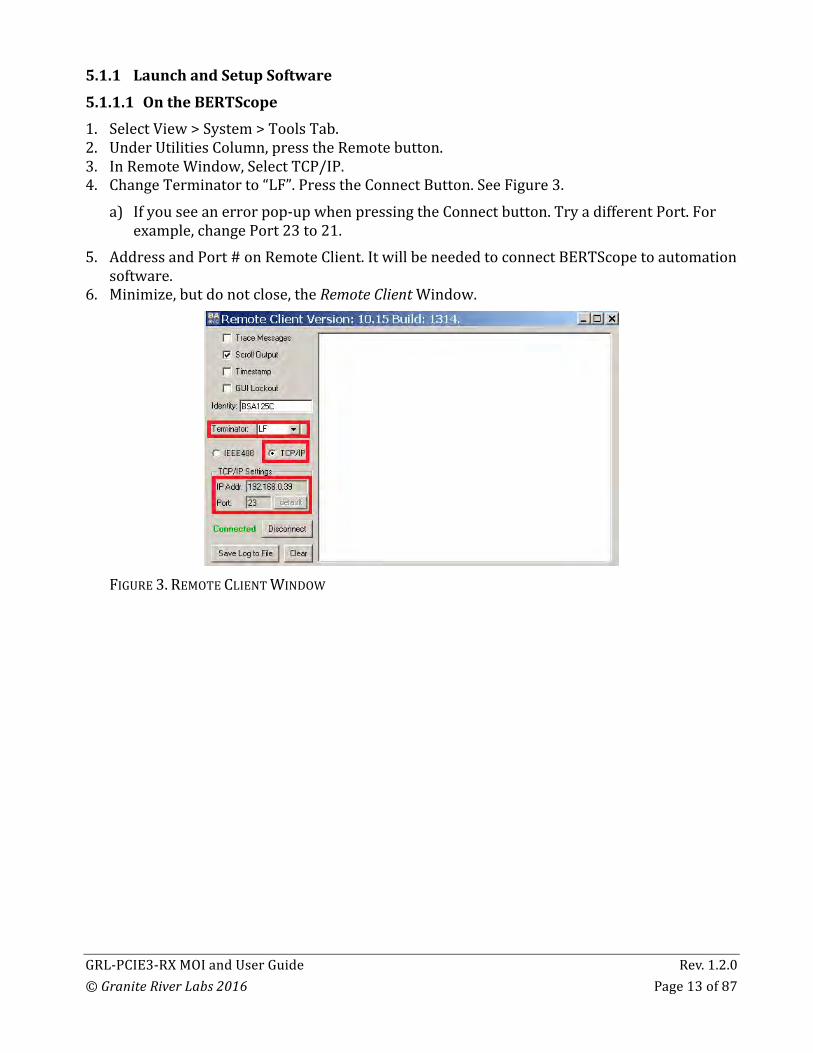
5.1.1 LaunchandSetupSoftware5.1.1.1 OntheBERTScope1. SelectView>System>ToolsTab.2. UnderUtilitiesColumn,presstheRemotebutton.3. InRemoteWindow,SelectTCP/IP.4. ChangeTerminatorto“LF”.PresstheConnectButton.SeeFigure3.
a) Ifyouseeanerrorpop-upwhenpressingtheConnectbutton.TryadifferentPort.Forexample,changePort23to21.
5. AddressandPort#onRemoteClient.ItwillbeneededtoconnectBERTScopetoautomationsoftware.
6. Minimize,butdonotclose,theRemoteClientWindow.
FIGURE3.REMOTECLIENTWINDOW

GRL-PCIE3-RXMOIandUserGuide Rev.1.2.0©GraniteRiverLabs2016 Page14of87
5.1.1.2 OnthePCUsedforGRLFrameworkInstallation.1. NavigatetoStartMenu>AllPrograms>GRL>GRLAutomatedTestSolutions.
FIGURE4.GRLAUTOMATEDTESTSOLUTIONSINSTARTMENU
2. ClickApplication>RxTestSolution>PCIe3.0BaseRxTesttoopentheapplication.
FIGURE5.RXTESTSOLUTIONSINGRLAUTOMATEDTESTSOLUTIONSWINDOW
GRL-PCIE3-RXMOIandUserGuide Rev.1.2.0©GraniteRiverLabs2016 Page15of87
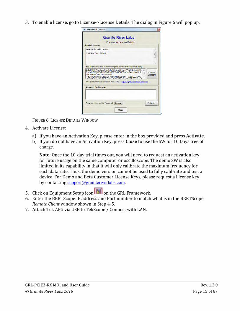
3. Toenablelicense,gotoLicense->LicenseDetails.ThedialoginFigure6willpopup.
FIGURE6.LICENSEDETAILSWINDOW
4. ActivateLicense:a) IfyouhaveanActivationKey,pleaseenterintheboxprovidedandpressActivate.b) IfyoudonothaveanActivationKey,pressClosetousetheSWfor10Daysfreeof
charge.Note:Oncethe10-daytrialtimesout,youwillneedtorequestanactivationkeyforfutureusageonthesamecomputeroroscilloscope.ThedemoSWisalsolimitedinitscapabilityinthatitwillonlycalibratethemaximumfrequencyforeachdatarate.Thus,thedemoversioncannotbeusedtofullycalibrateandtestadevice.ForDemoandBetaCustomerLicenseKeys,[email protected].
5. ClickonEquipmentSetupicon ontheGRLFramework.6. EntertheBERTScopeIPaddressandPortnumbertomatchwhatisintheBERTScope
RemoteClientwindowshowninStep4-5.7. AttachTekAFGviaUSBtoTekScope/ConnectwithLAN.
GRL-PCIE3-RXMOIandUserGuide Rev.1.2.0©GraniteRiverLabs2016 Page16of87
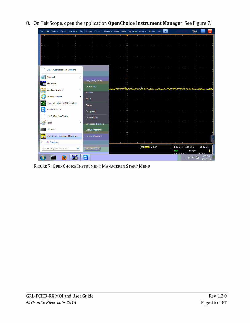
8. OnTekScope,opentheapplicationOpenChoiceInstrumentManager.SeeFigure7.
FIGURE7.OPENCHOICEINSTRUMENTMANAGERINSTARTMENU
GRL-PCIE3-RXMOIandUserGuide Rev.1.2.0©GraniteRiverLabs2016 Page17of87
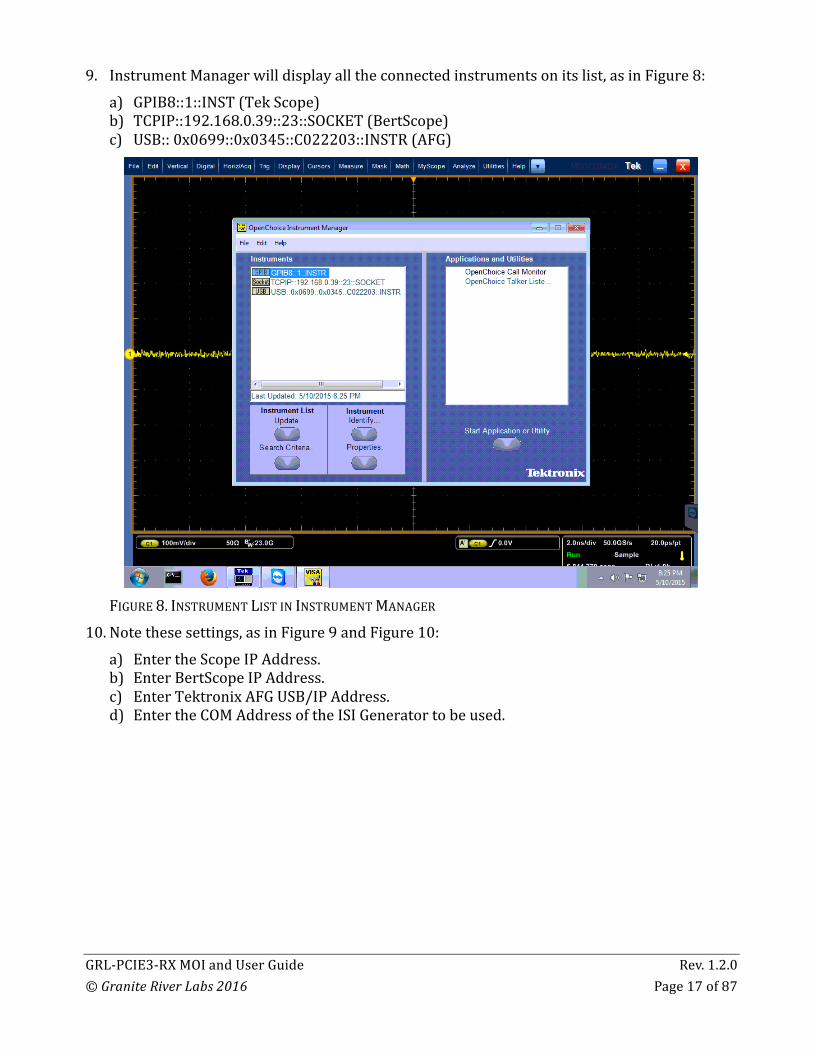
9. InstrumentManagerwilldisplayalltheconnectedinstrumentsonitslist,asinFigure8:a) GPIB8::1::INST(TekScope)b) TCPIP::192.168.0.39::23::SOCKET(BertScope)c) USB::0x0699::0x0345::C022203::INSTR(AFG)
FIGURE8.INSTRUMENTLISTININSTRUMENTMANAGER
10. Notethesesettings,asinFigure9andFigure10:a) EntertheScopeIPAddress.b) EnterBertScopeIPAddress.c) EnterTektronixAFGUSB/IPAddress.d) EntertheCOMAddressoftheISIGeneratortobeused.

GRL-PCIE3-RXMOIandUserGuide Rev.1.2.0©GraniteRiverLabs2016 Page18of87
FIGURE9.EQUIPMENTSETUPWINDOW–VIEW#1
FIGURE10.EQUIPMENTSETUPWINDOW–VIEW#2

GRL-PCIE3-RXMOIandUserGuide Rev.1.2.0©GraniteRiverLabs2016 Page19of87
11. Checktheconnectionbypressingthe“lightning”button .The“lightning”buttonshouldturngreeniftheconnectionhasbeenverified.
12. Dothisforeachinstrumentthatthatwillbeused,asshowninFigure11.
FIGURE11.EQUIPMENTSETUPWINDOW–VIEW#3
5.1.2 AdditionalNotesTheUSBdriverSWfortheISIGeneratorbeingusedmustbeinstalledonthePCbeingusedfortestingandtheISIGeneratormustbeconnectedtothePCviaUSB.ThedriverfortheISIGeneratorisavailablefromtheISIGeneratormanufacturer.RefertoAppendixofthisdocumentfordriverinstallationinformationforsupportedISIgenerators.
5.2 CalibratingUsingtheSoftware
5.2.1 SessionInfoTheinformationprovidedwillbeincludedinthereport.
The DUT Information and Test Info are input by the user.
The SW Versions information is automatically populated.
FIGURE12.SESSIONINFO

GRL-PCIE3-RXMOIandUserGuide Rev.1.2.0©GraniteRiverLabs2016 Page20of87
5.2.2 ConditionsforTestingandCalibrationInthissection,conditionsforTestingandCalibrationwillneedtobeset.Userselectsconditionsfortestingandforcalibration. Whencalibrating,theapplicationwillcalibratetheselectedrange,Sjfrequency,commonmodevoltageanddifferentialvoltagethattheuserchooses.Recommendedprocedure:1. Whencalibrating,selectconditionsforcalibrationandperformdesiredcalibration2. Whentesting:re-selectdesiredconditionsfortesting.Forexample,itmaybeonlynecessary
totestrangeAatSjfrequency.Theuserwouldselecttheappropriateconditionsfortest
FIGURE13.CONDITIONSFORTESTINGANDCALIBRATION
5.2.3 SetupConfiguration5.2.3.1 ISIGeneratorSetupIftestisrunningusingBERTScopeISITraceboard(FormoreinformationonhowtogeneratedesiredinsertionlossusingBERTScopeISITraceboard,pleaserefertoAppendixB),usercansettheISItoNONE.
FIGURE14.ISIGENERATORSETUP
GRL-PCIE3-RXMOIandUserGuide Rev.1.2.0©GraniteRiverLabs2016 Page21of87
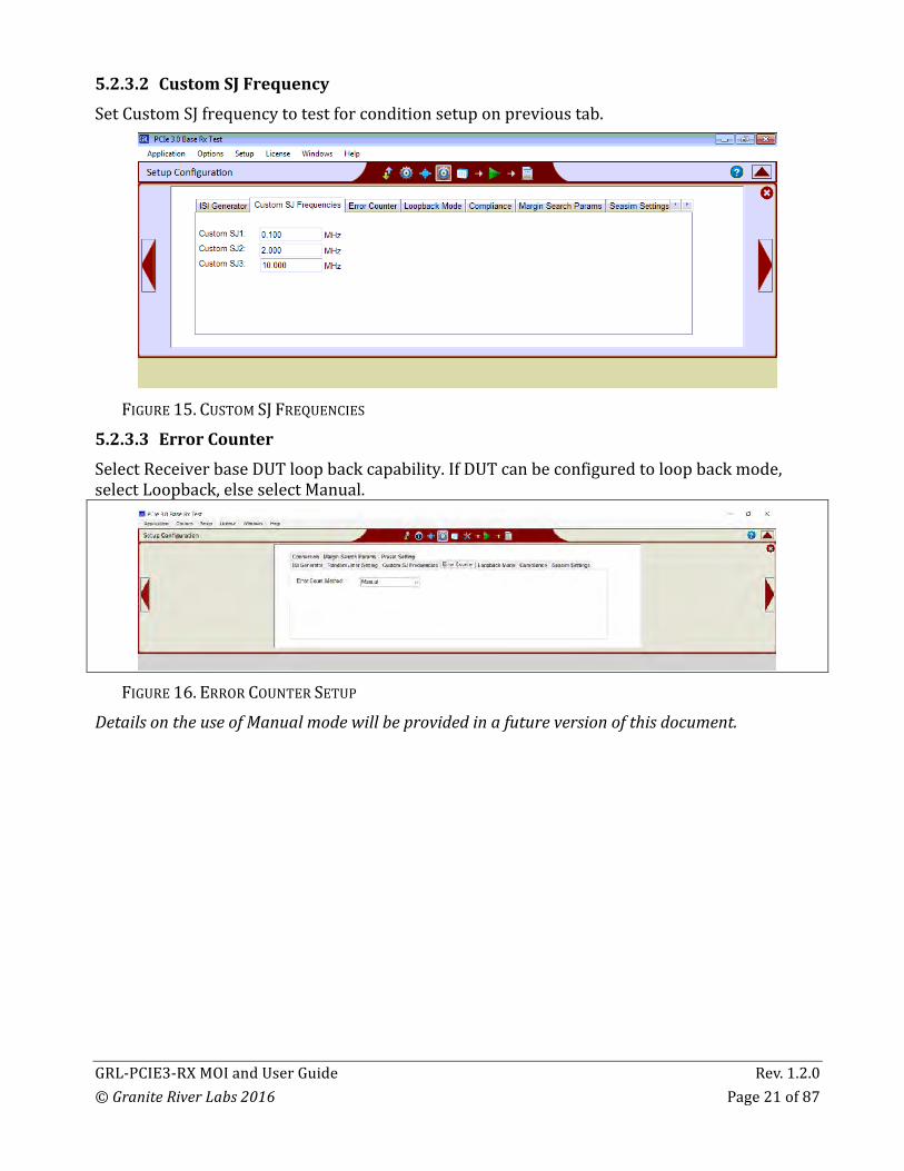
5.2.3.2 CustomSJFrequencySetCustomSJfrequencytotestforconditionsetuponprevioustab.
FIGURE15.CUSTOMSJFREQUENCIES
5.2.3.3 ErrorCounterSelectReceiverbaseDUTloopbackcapability.IfDUTcanbeconfiguredtoloopbackmode,selectLoopback,elseselectManual.
FIGURE16.ERRORCOUNTERSETUP
DetailsontheuseofManualmodewillbeprovidedinafutureversionofthisdocument.

GRL-PCIE3-RXMOIandUserGuide Rev.1.2.0©GraniteRiverLabs2016 Page22of87
5.2.3.4 LoopbackModeIftheuserselectedloopbackontheErrorCountertab,thentheuserneedstoselect“ClockRecovery”intheClockRecoveryMethoddrop-downontheLoopbackModetab.OtheroptionsontheClockRecoveryMethoddrop-downarenotyetsupported.
FIGURE17.LOOPBACKMODESETUP
PCIEusesthedefaultpattern.DetailsontheuseofCustomPatternswillbeprovidedinafutureversionofthisdocument.5.2.3.5 ComplianceTabSetBERandMaximumErrorallowedfortesting.TheselimitsaresetbytheSpecification.Otherlimitsmaybesetinthesefieldsbytheuser.Thesyntax‘1e-12’indicates10-12,andistheonlysyntaxsupportedinthisfield.
FIGURE18.BERANDMAXIMUMERRORS

GRL-PCIE3-RXMOIandUserGuide Rev.1.2.0©GraniteRiverLabs2016 Page23of87
5.2.3.6 SeasimTabSetifuserwishestousetheRxBehavioralpackageduringEyeHeightandEyeWidthCalibration.Alsosettheintrinsicjitter(ifrequired)tobeusedintheSeasimcalculation.
FIGURE19.SEASIMSETUP
Detailsontheuseof‘False’intheUserRxPackagefieldwillbeprovidedinafutureversionofthisdocument5.2.3.7 ConnectionTabSetupconnectionofData+andData-inScope.Scopechannelsshallbeassignedaccordingtohowthescopecablesareattachedtothetestsetup.
FIGURE20.CONNECTIONSETUP

GRL-PCIE3-RXMOIandUserGuide Rev.1.2.0©GraniteRiverLabs2016 Page24of87
5.2.4 SelectingCalibrationStepsUsingtheSoftwareTheSelectCalibrationTestspageistheplacewherethecalibrationteststhatneedtobeperformedareselected.Initially,whenstartingforthefirsttimeorchanginganythinginthesetup,itissuggestedtorunCalibrationfirst.Ifthecalibrationisnotcompleted,theRXTestswillshowanerrormessage.
FIGURE21.SELECTCALIBRATIONTESTSPAGE
5.2.5 RunCalibrationSteps
Fromthepop-upmenu,selecttheRunicon: SkipTestifResultsExist.Ifpreviouscalibrationresultsexist,thensoftwarewillskipcalibrationstepsthathaveexistingreports.ReplaceifResultsExist.Ifpreviouscalibrationresultsexist,thensoftwarewillreplaceeachstepincalibrationwithnewresults.(Restart)DeleteExistingResults.Allpreviousresultswillbedeleted,andeachselectedstepincalibrationwillgeneratenewreport.
FIGURE22.CONNECTIONSETUP

GRL-PCIE3-RXMOIandUserGuide Rev.1.2.0©GraniteRiverLabs2016 Page25of87
5.3 TestingusingGRL-PCIE3-BASE-RXSoftware
5.3.1 ReceiverComplianceTestsTheSelectTestspageistheplacewherethecomplianceteststhatneedtobeperformedareselected.
FIGURE23.SELECTCOMPLIANCETESTSPAGE
TestsarerunfromthesamescreenasshowninSection5.2.5.
5.3.2 ReceiverMarginTestsTheSelectTestspageistheplacewherethecomplianceteststhatneedtobeperformedareselected.
FIGURE24.SELECTMARGINTESTSPAGE
TestsarerunfromthesamescreenasshowninSection5.2.5.
5.4 ReportTheReportpagehasalltheresultsfromallthetestrunsdisplayed.Ifsomeoftheresultsarenotdesired,theycanbeindividuallydeletedbyusingtheDeletebutton.Alsoforapdfreport,clicktheGenerateReportbutton.Tohavethecalibrationdataplottedinthereport,makesurethePlotCalibrationDataboxischecked.

GRL-PCIE3-RXMOIandUserGuide Rev.1.2.0©GraniteRiverLabs2016 Page26of87
FIGURE25.REPORTRESULTSPAGE
5.5 InterpretingaReport
5.5.1 DUTInformationThisportionispopulatedfromtheinformationintheDUTtabfromtheSessionInfotab.
FIGURE26.DUTINFORMATION

GRL-PCIE3-RXMOIandUserGuide Rev.1.2.0©GraniteRiverLabs2016 Page27of87
5.5.2 SummaryTableThisportionispopulatedfromthetestsperformedanditsresults.Thisgivesanoverallviewofalltheresultsanditstestconditions.
FIGURE27.SUMMARYTABLE

GRL-PCIE3-RXMOIandUserGuide Rev.1.2.0©GraniteRiverLabs2016 Page28of87
5.5.3 CalibrationDataResultsIfPlotCalibrationDatacheckboxischecked,thentheplotsareshowninthispartofthereport.
FIGURE28.CALIBRATIONRESULTSEXAMPLE

GRL-PCIE3-RXMOIandUserGuide Rev.1.2.0©GraniteRiverLabs2016 Page29of87
5.5.4 ComplianceTestResults
FIGURE29.CALIBRATIONRESULTSEXAMPLE

GRL-PCIE3-RXMOIandUserGuide Rev.1.2.0©GraniteRiverLabs2016 Page30of87
5.5.5 JitterMarginResults
FIGURE30.JITTERMARGINREPORTEXAMPLE
6 TestSuiteThePCIE3BaseSpecificationtestsarelistedinthedrop-downmenusintheequipmentdescribedinthisMOI.
7 AppendixA:ARTEKCLE1000-A2Installation7.1 ISIGeneratorDriverInstallationIfusingARTEKCLE1000-A2forVariableISICalibration,followthesestepstoinstalltheISIgenerator driver before selecting it as an ISI channel in the DP Configuration Utility.
1. ConnecttheCLE1000-A2tothePCbeingusedasthecontroller,usingaUSB2.0cable.2. TurnonthefrontpanelpowerswitchontheCLE1000-A2.3. RightClickonMyComputer>Manage>DeviceManager.IfnoSWfortheCLE1000-A2has
beeninstalled,youwillseea‘bang’inthedevicemanager.SeeFigure31.

GRL-PCIE3-RXMOIandUserGuide Rev.1.2.0©GraniteRiverLabs2016 Page31of87
FIGURE31.DEVICEMANAGERWINDOW
4. ToinstalltheCLE1000-A2,gotohttp://www.aceunitech.com/support.htmlanddownloadtheControlSWpackagefortheCLE1000.
5. UnpacktheCLE1000SW.zipfile.6. InstalltheCLE1000Driver:
a) InDeviceManager,rightclickonCLE1000>UpdateDriver.b) SelectBrowseMyComputerforDriverfromWindowsdialog.SeeFigure32.c) BrowsetotherootdirectoryoftheunzippedCLE1000SWfolder.d) PressNext.Youwillbeaskedtoconfirmyourrequesttoinstalladriver.e) PressInstall.DriverSWwillcompleteinstallation.
7. Once Installationcompletes,theDeviceManagershouldlooklikeFigure34.
FIGURE32.UPDATEDRIVERWINDOW

GRL-PCIE3-RXMOIandUserGuide Rev.1.2.0©GraniteRiverLabs2016 Page32of87
FIGURE33.WINDOWSSECURITYWINDOWANDCONFIRMATIONWINDOW
FIGURE34.DEVICEMANAGERWINDOWAFTERINSTALLATION
TheCLE10000SWdriverisnowinstalledandtheCLE1000cannowbeselectedforuseremotely using the GRL DP Configuration Utility.

GRL-PCIE3-RXMOIandUserGuide Rev.1.2.0©GraniteRiverLabs2016 Page33of87
7.2 CLE1000GUIInstallationIt may also be useful to install the CLE1000 GUI, so that the ISI channel can also be controlled manually from the PC. To install the SW, do the following:
1. IntheCLE1000SWfolder,clickontheSetup.exefile.Onceinstalledsuccessfully,thefollowingGUIwillappearonthedesktop.
2. YoucannowclosetheGUIifyoudon’twanttohavemanualcontrol.
FIGURE35.CLE1000GUI
GRL-PCIE3-RXMOIandUserGuide Rev.1.2.0©GraniteRiverLabs2016 Page34of87
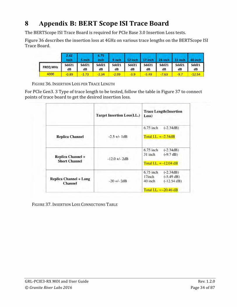
8 Appendix B: BERT ScopeISITraceBoard TheBERTScopeISITraceBoardisrequiredforPCIeBase3.0InsertionLosstests.Figure36describestheinsertionlossat4GHzonvarioustracelengthsontheBERTScopeISITraceBoard.
FIGURE36.INSERTIONLOSSPERTRACELENGTH
ForPCIeGen3.3Typeoftracelengthtobetested,followthetableinFigure37toconnectpointsoftraceboardtogetthedesiredinsertionloss.
FIGURE37.INSERTIONLOSSCONNECTIONSTABLE

GRL-PCIE3-RXMOIandUserGuide Rev.1.2.0©GraniteRiverLabs2016 Page35of87
9 AppendixC:ManualTestMethods9.1 WaveformTests
9.1.1 PreshootandDeemphasisPCIeBaseusestwopresetsfordifferenttracelengthsofthebreakoutboard.BothDeemphasisandPreshootarecalibratedforthetargetdBforeachpreset.SeeTable3.
TABLE3.PRESETSFORWAVEFORMTESTS
Preset Preshoot Deemphasis
4 0.0dB 3.5dB
7 0.0dB -6.0dB
9.1.1.1 BERTScopeSetup1. SettheBERTScopetodefaults.2. SetGeneratorto8Gpbs(PCIeGen3Speed)3. DisableAllstressedjittercomponent(Rj,Sjetc)4. SettheOutputamplitudeto800mV5. SettheDPPOutput460mV6. DefaulttheDPPto0.0dBPreshootandDeemphasis,asshowninFigure38.7. Loadwith64ONEs,64ZEROsand128ClkPatterntoBERTScope.
FIGURE38.BERTSCOPESETUP
GRL-PCIE3-RXMOIandUserGuide Rev.1.2.0©GraniteRiverLabs2016 Page36of87
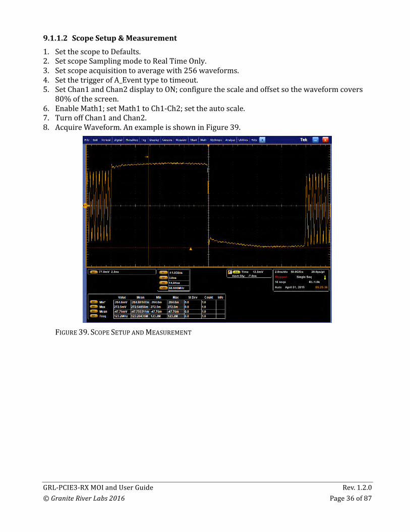
9.1.1.2 ScopeSetup&Measurement1. SetthescopetoDefaults.2. SetscopeSamplingmodetoRealTimeOnly.3. Setscopeacquisitiontoaveragewith256waveforms.4. SetthetriggerofA_Eventtypetotimeout.5. SetChan1andChan2displaytoON;configurethescaleandoffsetsothewaveformcovers
80%ofthescreen.6. EnableMath1;setMath1toCh1-Ch2;settheautoscale.7. TurnoffChan1andChan2.8. AcquireWaveform.AnexampleisshowninFigure39.
FIGURE39.SCOPESETUPANDMEASUREMENT

GRL-PCIE3-RXMOIandUserGuide Rev.1.2.0©GraniteRiverLabs2016 Page37of87
9.1.1.3 DeemphasisMeasurementNow,theactualde-emphasisandpre-shootmustbeverifiedonscope.1. Usingcursors,measurepeak-to-peaktransitionamplitudeasshownFigure40.
FIGURE40.MEASUREDTRANSITIONAMPLITUDE(EXAMPLE825MVPP)2. Usingcursors,measurepeak-to-peaknon-transitionamplitude,asshowninFigure41.
FIGURE41.MEASUREDNON-TRANSITIONAMPLITUDE(EXAMPLE254MV)
GRL-PCIE3-RXMOIandUserGuide Rev.1.2.0©GraniteRiverLabs2016 Page38of87
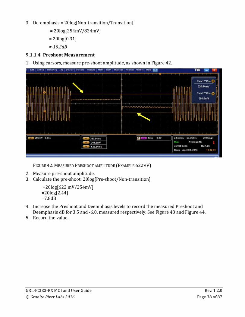
3. De-emphasis=20log[Non-transition/Transition]=20log[254mV/824mV]=20log[0.31]=-10.2dB9.1.1.4 PreshootMeasurement1. Usingcursors,measurepre-shootamplitude,asshowninFigure42.
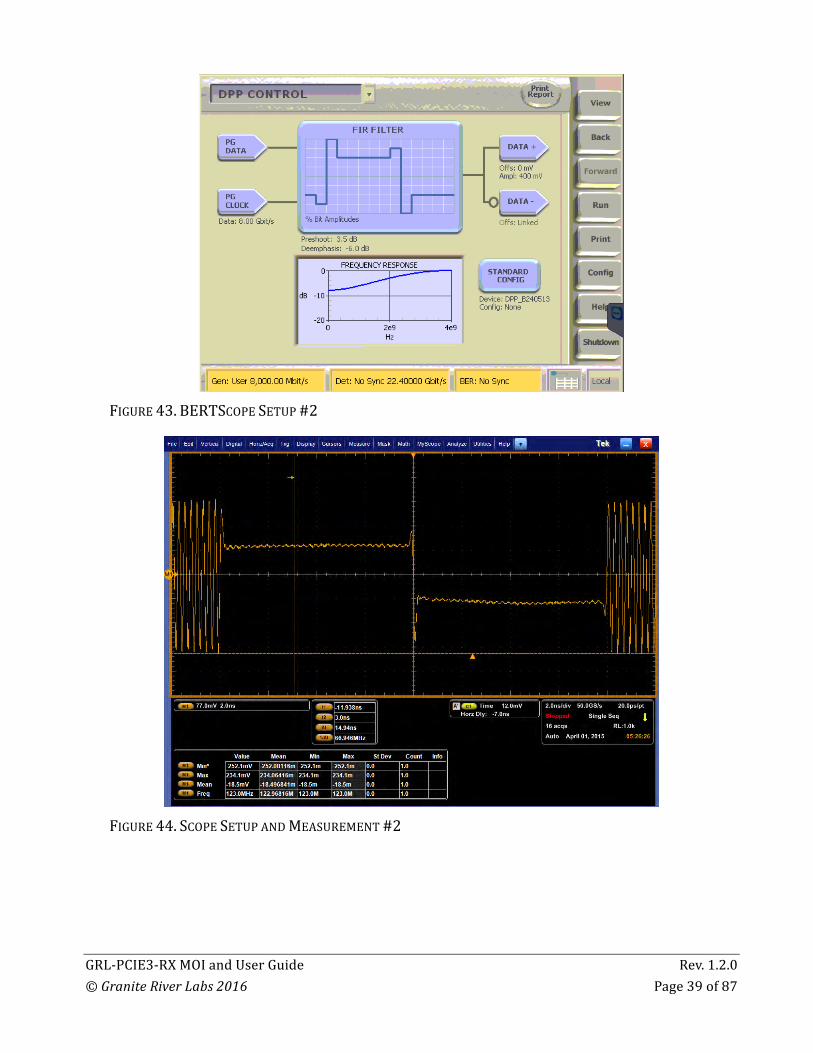
FIGURE42.MEASUREDPRESHOOTAMPLITUDE(EXAMPLE622MV)2. Measurepre-shootamplitude.3. Calculatethepre-shoot:20log[Pre-shoot/Non-transition]=20log[622mV/254mV]=20log[2.44]=7.8dB4. IncreasethePreshootandDeemphasislevelstorecordthemeasuredPreshootand
DeemphasisdBfor3.5and-6.0,measuredrespectively.SeeFigure43andFigure44.5. Recordthevalue.
GRL-PCIE3-RXMOIandUserGuide Rev.1.2.0©GraniteRiverLabs2016 Page39of87
FIGURE43.BERTSCOPESETUP#2
FIGURE44.SCOPESETUPANDMEASUREMENT#2
GRL-PCIE3-RXMOIandUserGuide Rev.1.2.0©GraniteRiverLabs2016 Page40of87
9.1.2 LaunchAmplitudeTheLaunchAmplitudeiscalibratedfortargetminimumpeak-to-peakamplitudeof800mVppaftercombiner.9.1.2.1 BERTScopeSetup1. UsingthesameTP1CalibrationSetup.2. SetDPPto0.0forPreshootandDeemphasis.3. SetDPPAmplitudeto300mV.4. SetPatterntoClk/256.9.1.2.2 ScopeSetupandMeasurement:1. UsingthesameSetup,ScaleChan1andChan2respectively.2. TurnoffChan1andChan2.3. TurnOnMath1,settoch1-ch2.4. SettheAcquisitionmodetoAverageof2565. SetMeasureAmplitudeofMath1.6. Acquirewaveform.7. ReadtheMEANvalueofamplitudemeasurement.8. TunetheDPPOutputuntilAmplitudemeasuredinscopeis800mV.
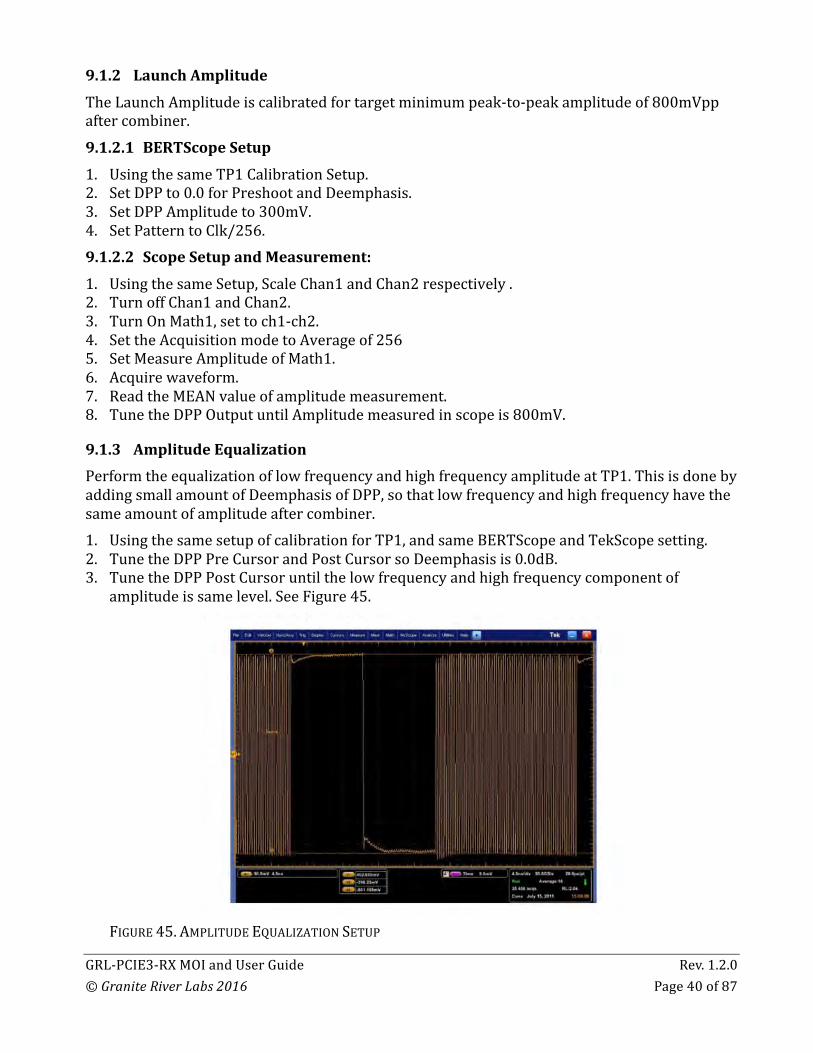
9.1.3 AmplitudeEqualizationPerformtheequalizationoflowfrequencyandhighfrequencyamplitudeatTP1.ThisisdonebyaddingsmallamountofDeemphasisofDPP,sothatlowfrequencyandhighfrequencyhavethesameamountofamplitudeaftercombiner.1. UsingthesamesetupofcalibrationforTP1,andsameBERTScopeandTekScopesetting.2. TunetheDPPPreCursorandPostCursorsoDeemphasisis0.0dB.3. TunetheDPPPostCursoruntilthelowfrequencyandhighfrequencycomponentof
amplitudeissamelevel.SeeFigure45.
FIGURE45.AMPLITUDEEQUALIZATIONSETUP

GRL-PCIE3-RXMOIandUserGuide Rev.1.2.0©GraniteRiverLabs2016 Page41of87
4. SavethePostCursorvalue.
9.1.4 RJCalibration1. UsingaClockpattern(1100),theRJvalueof0ps-5pswillbecalibrated.(Bothlimitsare
RMSvalues.)RJisusedtoadjusttheEyeWidth(EW)inStressJitterTest.2. RJtargetis2ps(RMS).3. TektronixDPOJETisusedasthecalibrationtool.9.1.4.1 BERTScopeSetup1. SettheGeneratorto8Gpbs.2. SettheSub-rateclockmodeisStressedClock.3. SettheRJEnable.4. SettheSJEnable,SettheSJAmplitudeto0.0mV.SeeFigure46.
FIGURE46.BERTSCOPEJITTERSETUP

GRL-PCIE3-RXMOIandUserGuide Rev.1.2.0©GraniteRiverLabs2016 Page42of87
5. SetthePatternofgeneratorto1100.ram(1-1-0-0pattern).SeeFigure47.
FIGURE47.BERTSCOPEPATTERNSETUP
9.1.4.2 DPPSetup1. SettheDPPPreShootandDeEmphasisusingP4preset(0.0dbforboth).2. Setthepostcursorandprecursorbasedonequalizedamplitudevaluerecordedearlier.3. SetDPPoutputthatreflect800mVamplitudethatrecordedearlier.9.1.4.3 ScopeSetup1. SettheDPOJETConfigure->ClockRecoverytoConstantClockMean.
FIGURE48.DPOJETCONFIGURESETUP

GRL-PCIE3-RXMOIandUserGuide Rev.1.2.0©GraniteRiverLabs2016 Page43of87
2. UnderRJDJsettingsforclocksignal.
FIGURE49.RJDJSETUP
3. OntheAdvancePanel,settheNominalDataRateto8Gpbs.
FIGURE50.SCOPEADVANCEDSETUP

GRL-PCIE3-RXMOIandUserGuide Rev.1.2.0©GraniteRiverLabs2016 Page44of87
4. SettheHorizontalmodetoManual,setrecordlengthto2M.
FIGURE51.SCOPERECORDLENGTHSETUP
5. Cleartheresult.RunSingle.
FIGURE52.SCOPEWAVEFORMCAPTURE
6. ReadthemeasuredRJ1.

GRL-PCIE3-RXMOIandUserGuide Rev.1.2.0©GraniteRiverLabs2016 Page45of87
7. TunetheBertScopeRJvalue.
FIGURE53.BERTSCOPERJCAPTURE
8. ThetargetmeasuredvalueforRJ:2psRMSand3psRMS.
9.1.5 SJCalibrationTherearefourSJ(SweepJitter)frequenciesrequired:30KHz,1MHz,10MHzand100MHz.SJneedstobecalibrated(with1100pattern)forallcasesintheproperway.
TABLE4.STRESSEDJITTERTESTS
Frequency
30KHz
1MHz
10MHz
100MHz 0.1 UIPP
StressedVoltageTest:
StressedJitterTest:
GRL-PCIE3-RXMOIandUserGuide Rev.1.2.0©GraniteRiverLabs2016 Page46of87
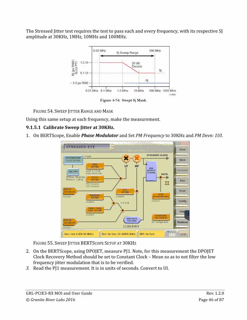
TheStressedJittertestrequiresthetesttopasseachandeveryfrequency,withitsrespectiveSJamplitudeat30KHz,1MHz,10MHzand100MHz.
FIGURE54.SWEEPJITTERRANGEANDMASK
Usingthissamesetupateachfrequency,makethemeasurement.9.1.5.1 CalibrateSweepJitterat30KHz.1. OnBERTScope,EnablePhaseModulatorandSetPMFrequencyto30KHzandPMDevn:1UI.
FIGURE55.SWEEPJITTERBERTSCOPESETUPAT30KHZ
2. OntheBERTScope,usingDPOJET,measurePJ1.Note,forthismeasurementtheDPOJETClockRecoveryMethodshouldbesettoConstantClock–Meansoastonotfilterthelowfrequencyjittermodulationthatistobeverified.
3. ReadthePJ1measurement.Itisinunitsofseconds.ConverttoUI.

GRL-PCIE3-RXMOIandUserGuide Rev.1.2.0©GraniteRiverLabs2016 Page47of87
9.1.5.2 CalibrateSweepJitterat1MHz,10MHz,100MHz1. SetSineJitterinitiallyto10%UI.
FIGURE56.SWEEPJITTERBERTSCOPESETUPAT1MHZ-100MHZ
1. MeasureSJusingDPOJET.
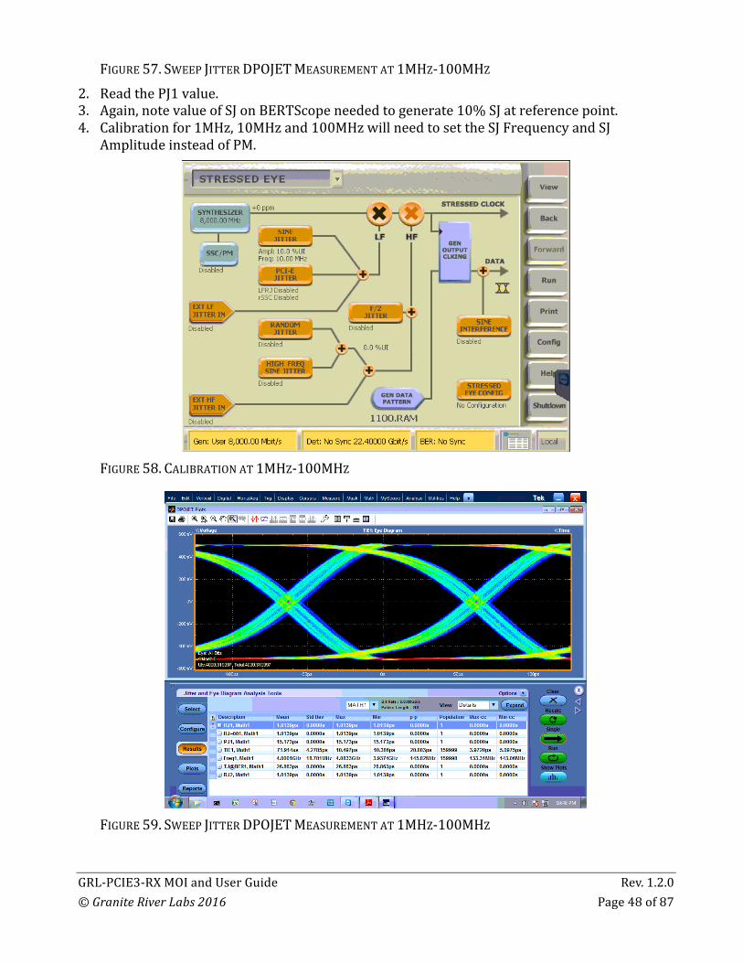
GRL-PCIE3-RXMOIandUserGuide Rev.1.2.0©GraniteRiverLabs2016 Page48of87
FIGURE57.SWEEPJITTERDPOJETMEASUREMENTAT1MHZ-100MHZ2. ReadthePJ1value.3. Again,notevalueofSJonBERTScopeneededtogenerate10%SJatreferencepoint.4. Calibrationfor1MHz,10MHzand100MHzwillneedtosettheSJFrequencyandSJ
AmplitudeinsteadofPM.
FIGURE58.CALIBRATIONAT1MHZ-100MHZ
FIGURE59.SWEEPJITTERDPOJETMEASUREMENTAT1MHZ-100MHZ

GRL-PCIE3-RXMOIandUserGuide Rev.1.2.0©GraniteRiverLabs2016 Page49of87
9.2 ChannelCalibrationTests(TP2)
9.2.1 ChannelCalibrationInsertionLossPCIeGen3defines3typesofcalibrationchannel.1. None2. Short3. LongDefinedbyFigure60,eachchannelinsertionlossmustmeetthemaskdependingonitschanneltype.VariableandprogrammableISIinjectorisneededtosimulatethetracelengthtoachievethetargetlossforeachchannel.
FIGURE60.CHANNELINSERTIONLOSSMASKBYCHANNELTYPE
Insertionlossismeasuredbydifferentiatingstepresponse,anddoingtheFFToftheresultingimpulseresponse.TheSeasimapplicationprovidesthemethodtocalculationtheinsertionlossgiventhestepresponse.9.2.1.1 BERTScopeSetup1. SetBERTScopeSetPatterntoclk/256.2. SetDPPSetDeemphasisandPreshoottoP4withpostcursorandprecursorforequalization
ofamplituderecordedearlier.3. SetDPPoutputthatreflectsthe800mVamplitudethatwasrecordedearlier.4. DisableRj.5. DisableSj.9.2.1.2 ISISetup1. OpentheArtekISIapplication.

GRL-PCIE3-RXMOIandUserGuide Rev.1.2.0©GraniteRiverLabs2016 Page50of87
2. SettheISI%to0.0.
FIGURE61.ISISETUP
9.2.1.3 ScopeSetup1. TurnOnCh1andCh2,scalech1andch2correctly.2. TurnOffch1andch23. TurnONMath1,setch1-ch2.Scalecorrectly.4. SetupTriggerAEventtoEdge,sourcetochan1,5. SetupTriggerA-BEventwithAcquisitionDelayto4ns.
FIGURE62SCOPESETUP#1
FIGURE63SCOPESETUP#2

GRL-PCIE3-RXMOIandUserGuide Rev.1.2.0©GraniteRiverLabs2016 Page51of87
6. SetupAcquisitionModetoAverageof2048Waveforms.
FIGURE64SCOPEACQUISITIONMODESETUP
7. RunSingleandcapturemeasurement.
FIGURE65CAPTUREMEASUREMENT
8. SavetheWaveformto.DATformat.9. Modifythe.datformattoSeasimcompatiblewaveformwithnameending_vict.rfstep1.10. The_vict.rfstep1formatisconsistoftime[SPACE]Voltage_level[NewLine].11. Copythe_vict.rfstep1stepresponseto\step_responsefolder.

GRL-PCIE3-RXMOIandUserGuide Rev.1.2.0©GraniteRiverLabs2016 Page52of87
12. LaunchSeasim_GUI.pyw.
FIGURE66SAVETHEWAVEFORM
13. ChangethefilenameBasenameSteptothefilenamesavedandmodified.14. ClickRun.

GRL-PCIE3-RXMOIandUserGuide Rev.1.2.0©GraniteRiverLabs2016 Page53of87
15. Seasimwilloutputgraphindicatingtheinsertionloss.
FIGURE67SEASIMINSERTIONLOSSOUTPUTGRAPH
16. Insertionlossat4GHzis-9dBforsampleabove.17. IncreasetheISI%thenrecapturethewaveform,save,modifyandrunSeasim.18. EnsuretheinsertionlossisbetweenthePCIeGen3specsforrespectivechanneltype.

GRL-PCIE3-RXMOIandUserGuide Rev.1.2.0©GraniteRiverLabs2016 Page54of87
9.2.1.4 ExampleResults
FIGURE68SPECIFICATIONMASK
FIGURE69INSERTIONLOSSAT27.5%ISI(-16.9DB)

GRL-PCIE3-RXMOIandUserGuide Rev.1.2.0©GraniteRiverLabs2016 Page55of87
FIGURE70INSERTIONLOSSAT30.%ISI(-17.9DB)
FIGURE71INSERTIONLOSSAT32.5%ISI(-18.9DB)WITHINTARGET

GRL-PCIE3-RXMOIandUserGuide Rev.1.2.0©GraniteRiverLabs2016 Page56of87
FIGURE72INSERTIONLOSSCALIBRATIONFORLONGCHANNEL–ILFALLSBETWEENREQUIREDMASK
9.2.2 ChannelCalibrationDifferentialModeSinusoidalInterference9.2.2.1 BERTScopeSetup1. SetALLZEROPattern.
FIGURE73BERTSCOPESETUPFORALLZEROPATTERN
GRL-PCIE3-RXMOIandUserGuide Rev.1.2.0©GraniteRiverLabs2016 Page57of87
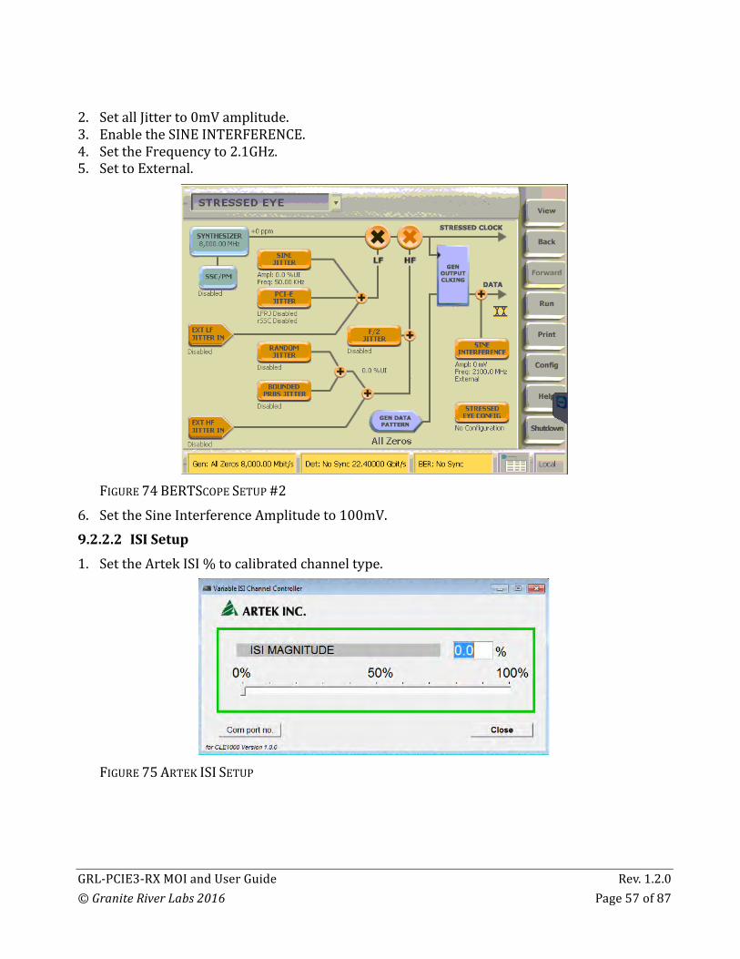
2. SetallJitterto0mVamplitude.3. EnabletheSINEINTERFERENCE.4. SettheFrequencyto2.1GHz.5. SettoExternal.
FIGURE74BERTSCOPESETUP#2
6. SettheSineInterferenceAmplitudeto100mV.9.2.2.2 ISISetup1. SettheArtekISI%tocalibratedchanneltype.
FIGURE75ARTEKISISETUP

GRL-PCIE3-RXMOIandUserGuide Rev.1.2.0©GraniteRiverLabs2016 Page58of87
9.2.2.3 ScopeSetup1. SetAcquisitionAverageto256.2. ScaleCh1andCh2accordingly.3. TurnonMATH1,ch1-ch2,scaleaccordingly.4. MeasurePeaktoPeakofMath1.5. RunSingle.6. ObtaintheMEANvalueofmath1peaktopeak.7. TunetheSineInterferenceAmplitudesomeasuredvalueis16mV.
FIGURE76SCOPEMEASUREMENT
9.2.3 ChannelCalibrationACCommonModeSinusoidalInterference9.2.3.1 BERTScopeSetup1. RemainALLZEROPattern.2. SettheSINEInterferenceamplitudeto0mV.9.2.3.2 SetupAFG1. EnabletheAFGoutput1.2. SettheOutputModetoSINEwave.3. SettheSINEWavefrequencyto120MHz.4. SettheOutput1Amplitudeto1V.

GRL-PCIE3-RXMOIandUserGuide Rev.1.2.0©GraniteRiverLabs2016 Page59of87
9.2.3.3 ScopeSetup1. ScaleCh1andCh2.2. SetMATH1toch1+ch2.ScaleMATH1.3. TurnOFFCh1andCH2.4. SetAcquisitiontoAverage256.
FIGURE77SCOPEMEASUREMENT
5. TunetheAFGAmplitude.6. TargetCM:
150mVforLongChannel250mVforShortandNoneChannel
9.3 CalibrationatTP2PTwodistincttestsareutilizedtotestareceiver:oneforitsminimumeyeheight(voltage),andanotherforitsminimumeyewidth(jitter).Theproceduresforcalibratingthestressedeyearesimilar,althoughthenumberandmagnitudeofsignalimpairmentsourcesvariesbetweenthetwotests.

GRL-PCIE3-RXMOIandUserGuide Rev.1.2.0©GraniteRiverLabs2016 Page60of87
9.3.1 TP2PStressedVoltageCalibrationTheconfigurationforcalibratingastressedvoltageeyeforRxtestingisshownbelowwherethecalibrationprocedureisperformedforallthreecalibration/breakoutchannelcombinations.RjandSjareaddedasdefinedinbelowandcommonmodeanddifferentialmodenoisesourcesareaddedsimultaneously.
FIGURE78SETUPFORCALCULATINGTHESTRESSEDVOLTAGEEYE
FIGURE79STRESSEDVOLTAGEEYEPARAMETERS

GRL-PCIE3-RXMOIandUserGuide Rev.1.2.0©GraniteRiverLabs2016 Page61of87
EyewidthandeyeheightaredefinedafterapplyingpostprocessingandaredefinedatTP2P.ThelongcalibrationchannelutilizesbothCTLEandDFE,whilethemediumandshortchannelscalibrationchannelsuseCTLEonly.EHissetbyadjustingtheamountofdifferentialnoiseuntilthevaluedefinedbyVRX-SV-8Gisobtained.Ifitisnotpossibletomaintainasufficienteyewidthbyadjustingonlythedifferentialnoise,itisacceptabletoinjectlessdifferentialnoiseandadjustthegeneratorlaunchvoltage.SeasimisusedtopostprocessthereceivereyeatTP2P.Inthiscontext,Rj,Sj,DM-SIsourceareinputtoSeasim.WhileCMSIarecombinedwithclk/256patternsourcefromBERTandcapturedinScope.9.3.1.1 BERTScopeSetup1. SetBERTScopePatterntoclk/2562. TurnOffRj,Sj,DM-SiatBERTScope.3. SetDPPOuputto800mVAmplitudecalibratedearlier.4. SetDPPDeEmphasisandPreshoot.Use“Preset4forShortandNonechannel.UsePreset7
forLongchannel.9.3.1.2 AFGSetup1. TurnOffAFG9.3.1.3 ScopeSetup1. SetupTriggerAEventtoEdge,sourcetochan1,2. SetupTriggerA-BEventwithAcquisitionDelayto4ns.
FIGURE80SCOPESETUP
GRL-PCIE3-RXMOIandUserGuide Rev.1.2.0©GraniteRiverLabs2016 Page62of87
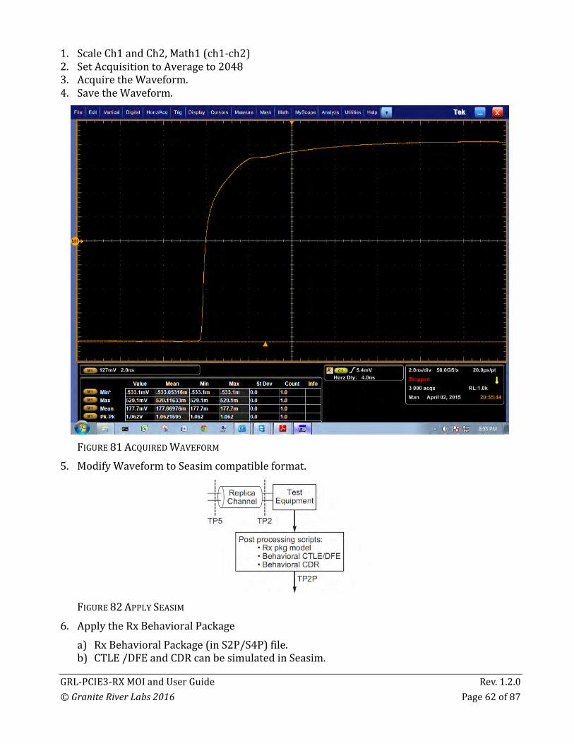
1. ScaleCh1andCh2,Math1(ch1-ch2)2. SetAcquisitiontoAverageto20483. AcquiretheWaveform.4. SavetheWaveform.
FIGURE81ACQUIREDWAVEFORM
5. ModifyWaveformtoSeasimcompatibleformat.
FIGURE82APPLYSEASIM
6. ApplytheRxBehavioralPackagea) RxBehavioralPackage(inS2P/S4P)file.b) CTLE/DFEandCDRcanbesimulatedinSeasim.

GRL-PCIE3-RXMOIandUserGuide Rev.1.2.0©GraniteRiverLabs2016 Page63of87
c) RxPackagemodelisconvolutedexternallywithStepresponsebeforeinputtoSeasimd) StepresponseisconverttoFrequencydomain,thenmultiplythemagnitudewiths2p
S21magnitudeandphasecorrespondingtoitsfrequencyrange.e) Itcanberealizedusingpythonscript.f) Acomparisonoforiginalfrequencyresponse(red),andtheafterapplicationofs2p
(purple),showingthes2pRxpackages21graphasagreenline.
FIGURE83GRAPHICALCOMPARISONOFORIGINALANDAFTER-APPLICATIONRESPONSEg) Stepresponsebefore(red)andafter(purple).
FIGURE84GRAPHICALSTEPRESPONSECOMPARISON
7. RunSeasim:a) SettheBaseNameforSteptofilenamesaved.
GRL-PCIE3-RXMOIandUserGuide Rev.1.2.0©GraniteRiverLabs2016 Page64of87
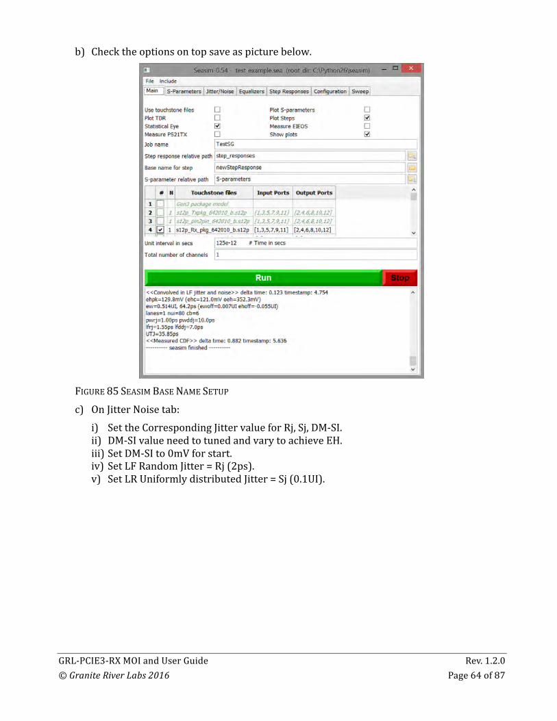
b) Checktheoptionsontopsaveaspicturebelow.
FIGURE85SEASIMBASENAMESETUPc) OnJitterNoisetab:
i) SettheCorrespondingJittervalueforRj,Sj,DM-SI.ii) DM-SIvalueneedtotunedandvarytoachieveEH.iii) SetDM-SIto0mVforstart.iv) SetLFRandomJitter=Rj(2ps).v) SetLRUniformlydistributedJitter=Sj(0.1UI).

GRL-PCIE3-RXMOIandUserGuide Rev.1.2.0©GraniteRiverLabs2016 Page65of87
vi) SetLFUniformlyDistributedVoltageNoise=DM-SI14mVormore.
FIGURE86SEASIMJITTER/NOISESETUPd) OnEqualizertab:
i) SettheDFEtapsandmaxMagnitude.ii) IfLongchannelsetto[0.000](DisableDFE)iii) IfShortandNone,setto[0.030],EnablewithMaxof30mV.
FIGURE87SEASIMEQUALIZERSETUPe) RunSimulation.

GRL-PCIE3-RXMOIandUserGuide Rev.1.2.0©GraniteRiverLabs2016 Page66of87
8. SimulatedEyeDiagramwillbecreated,withitscalculatedEHandEWatBER-12basedonjitterinput.
FIGURE88SEASIMSIMULATEDEYEDIAGRAM#1
9. ObservetheEHandEW.

GRL-PCIE3-RXMOIandUserGuide Rev.1.2.0©GraniteRiverLabs2016 Page67of87
10. ChangetheDM-SIvalueto15mVandrunsimulationagain.
FIGURE89SEASIMSIMULATEDEYEDIAGRAM#2

GRL-PCIE3-RXMOIandUserGuide Rev.1.2.0©GraniteRiverLabs2016 Page68of87
11. ChangetheDM-SIvalueto16mVandrunsimulationagain.
FIGURE90SEASIMSIMULATEDEYEDIAGRAM#3
12. CalibrateuntilEHisobtained.(*)IfEWrangecannotbeachieved,IncreasetheAmplitudefrom800mVto900mVandperformtheStressVoltagecalibrationagainuntilEHandEWareobtained.
9.3.2 StressedJitterCalibration(ForLongChannelOnly)Thestressedjittercalibrationprocedureissimilartothatofstressedvoltage.Onlythelongcalibrationchannel(-20dB)isused.Notethatthesamepostprocessingscriptsareappliedidenticallyastheyareforthestressedvoltageeyecase.Eyewidthisfine-tunedbymakingadjustmentstotheRjsource,whileEHmaybeadjustedbyvaryingthelaunchvoltageatthegenerator.

GRL-PCIE3-RXMOIandUserGuide Rev.1.2.0©GraniteRiverLabs2016 Page69of87
FIGURE91LAYOUTFORLONGCHANNELCALIBRATION
FIGURE92SPECIFICATIONFORLONGCHANNELCALIBRATION
9.3.2.1 BERTScopeSetup1. SetBERTScopePatterntoclk/2562. TurnOffRj,Sj,DM-SiatBERTScope.3. SetDPPOutputto800mVAmplitudecalibratedearlier.4. SetDPPDeemphasisandPreshoottoPreset7forShortchannel.Preset4forotherchannel
Type.5. TurnOffAFG.

GRL-PCIE3-RXMOIandUserGuide Rev.1.2.0©GraniteRiverLabs2016 Page70of87
9.3.2.2 ScopeSetup1. SetupTriggerAEventtoEdge,sourcetochan1,2. SetupTriggerA-BEventwithAcquisitionDelayto4ns.
FIGURE93SCOPESETUP3. ScaleCh1andCh2,Math1(ch1-ch2).4. SetAcquisitiontoAverageto2048.5. AcquireWaveform.6. SaveWaveform.7. ModifyWaveformtoSeasimcompatibleformat.
GRL-PCIE3-RXMOIandUserGuide Rev.1.2.0©GraniteRiverLabs2016 Page71of87
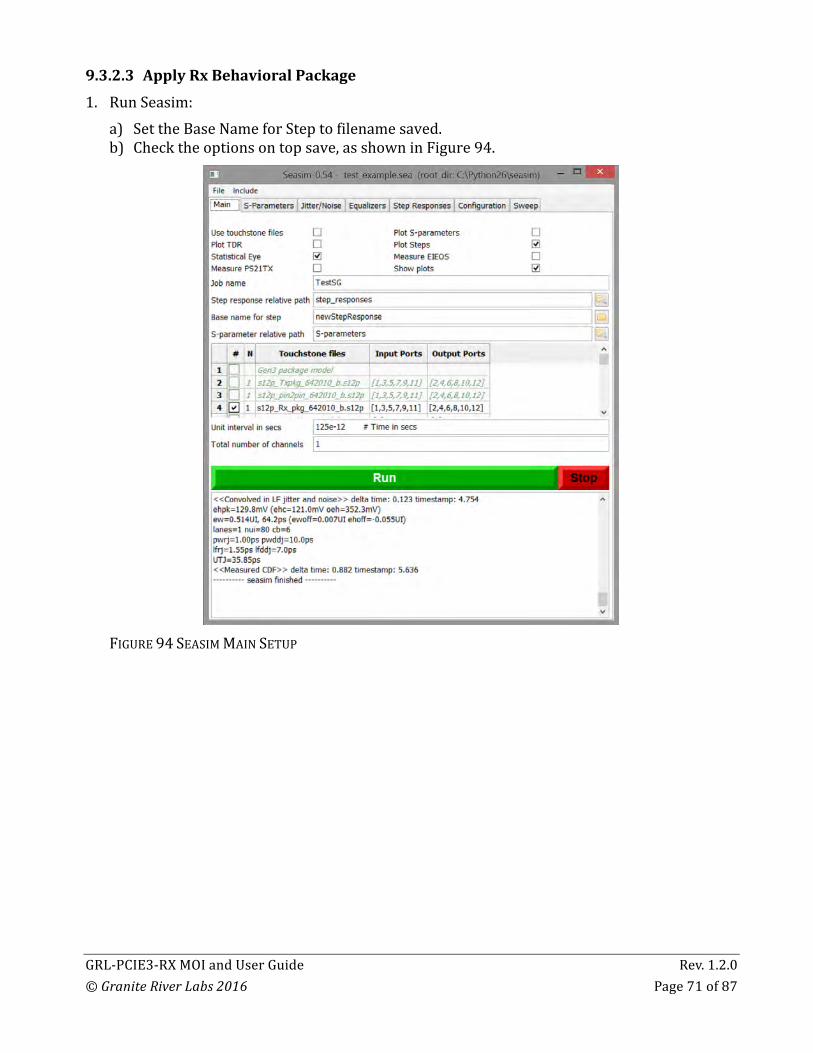
9.3.2.3 ApplyRxBehavioralPackage1. RunSeasim:
a) SettheBaseNameforSteptofilenamesaved.b) Checktheoptionsontopsave,asshowninFigure94.
FIGURE94SEASIMMAINSETUP
GRL-PCIE3-RXMOIandUserGuide Rev.1.2.0©GraniteRiverLabs2016 Page72of87
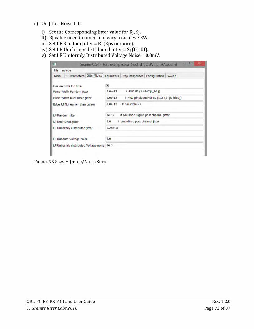
c) OnJitterNoisetab.i) SettheCorrespondingJittervalueforRj,Sj.ii) RjvalueneedtotunedandvarytoachieveEW.iii) SetLFRandomJitter=Rj(3psormore).iv) SetLRUniformlydistributedJitter=Sj(0.1UI).v) SetLFUniformlyDistributedVoltageNoise=0.0mV.
FIGURE95SEASIMJITTER/NOISESETUP

GRL-PCIE3-RXMOIandUserGuide Rev.1.2.0©GraniteRiverLabs2016 Page73of87
d) Equalizertab:i) SettheDFEtapsandmaxMagnitude.ii) Setto[0.030].
FIGURE96SEASIMEQUALIZERSETUPe) RunSimulation.

GRL-PCIE3-RXMOIandUserGuide Rev.1.2.0©GraniteRiverLabs2016 Page74of87
2. SimulatedEyeDiagramwillbecreatedwithitscalculatedEHandEWatBER-12basedonjitterinput.
FIGURE97WAVEFORM#1
3. ObservetheEHandEW.4. ChangetheRjvalueandrunsimulationagain.5. CalibrateuntilEWisobtained.(*)IfEHrangecannotbeachieved,IncreasetheAmplitudefrom800mVto900mVandperformtheStressJittercalibrationagainuntilEHandEWareobtained.
GRL-PCIE3-RXMOIandUserGuide Rev.1.2.0©GraniteRiverLabs2016 Page75of87
9.4 ReceiverTest
9.4.1 EquipmentSetup
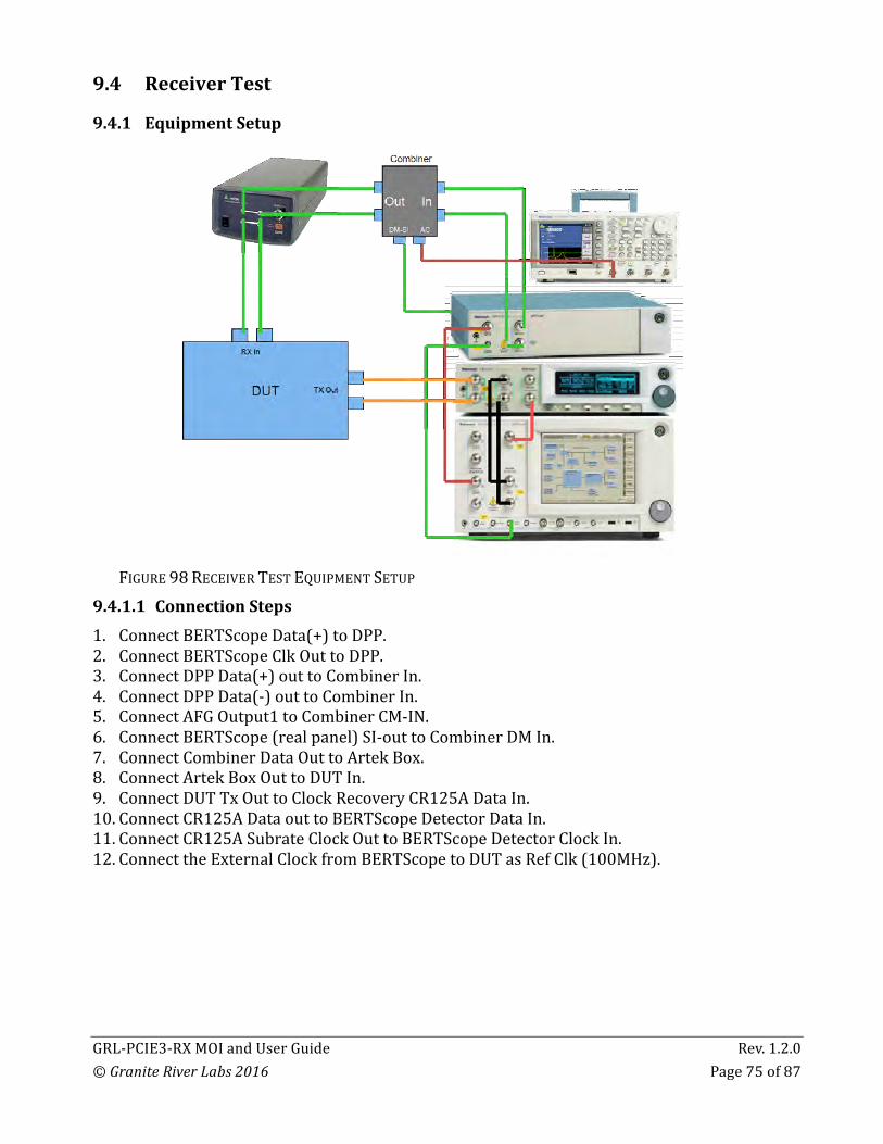
FIGURE98RECEIVERTESTEQUIPMENTSETUP
9.4.1.1 ConnectionSteps1. ConnectBERTScopeData(+)toDPP.2. ConnectBERTScopeClkOuttoDPP.3. ConnectDPPData(+)outtoCombinerIn.4. ConnectDPPData(-)outtoCombinerIn.5. ConnectAFGOutput1toCombinerCM-IN.6. ConnectBERTScope(realpanel)SI-outtoCombinerDMIn.7. ConnectCombinerDataOuttoArtekBox.8. ConnectArtekBoxOuttoDUTIn.9. ConnectDUTTxOuttoClockRecoveryCR125ADataIn.10. ConnectCR125ADataouttoBERTScopeDetectorDataIn.11. ConnectCR125ASubrateClockOuttoBERTScopeDetectorClockIn.12. ConnecttheExternalClockfromBERTScopetoDUTasRefClk(100MHz).

GRL-PCIE3-RXMOIandUserGuide Rev.1.2.0©GraniteRiverLabs2016 Page76of87
9.4.2 StressedVoltageReceiverTestOnceacalibratedEHandEWhavebeenobtained,thecablesaremovedtoconnecttheRxDUTtothefarendofcalibrationchannel.TheTxequalizationisthenoptimizedasitwasforthestressedvoltageeyewiththeassumptionthattheDUTRxwillalsooptimizeitsequalization.SjissettoaninitialvaluethatpermitsthereceiverCDRtoachievelock.9.4.2.1 ConfigureBERTScope1. SetGeneratorto8Gpbs.2. SetthePatterntoPCIe_8G_BruteFor.RAM.
FIGURE99RECEIVERTESTCONFIGUREBERTSCOPE

GRL-PCIE3-RXMOIandUserGuide Rev.1.2.0©GraniteRiverLabs2016 Page77of87
9.4.2.2 ConfigureforStressedJitter1. SettheCalibratedSJfor0.1UIat100MHz.2. SettheCalibratedRjfor2ps(RMS).3. SettheCalibratedSineInterferenceAmplitudethatiscalibratedtoachieveEHandEW(DM-
SI).4. SettheSineInterferenceFrequencyto2.1GHz.5. SettheSineInterferencemodetoExternal.6. SettheDPPOutputtocalibratedamplitudetoachieveEHandEW.
FIGURE100RECEIVERTESTCONFIGUREFORSTRESSEDJITTER
7. ConfigureISIbysettingArtekISI%valuetocalibratedchannelType.8. ConfigureAFG:
a) SetOutput1ofAFGONb) SetOutput1ModetoSineWavec) SetSineWaveFrequencyto120MHzd) SettheSineWaveAmplitudetoCalibratedvalue.
9. SetuptheBERTScopeDetector:a) ClicktheAutoAlign

GRL-PCIE3-RXMOIandUserGuide Rev.1.2.0©GraniteRiverLabs2016 Page78of87
FIGURE101RECEIVERTESTCONFIGUREBERTSCOPEDETECTOR
9.4.2.3 BitErrorRateTest1. WiththeDUTinloopbackmode,andBERTScopesynchronizewithpattern.2. Compliancetestmaybegin.3. ClicktheResetResult.4. ClicktheRUN.5. LettheDetectorRun,stopwhentheBITsismorethan1xE12.6. ReadtheErrorvalue.7. Iftheerroriszero(0),thenthetestpasses.
FIGURE102RECEIVERTESTPERFORMBERTEST
GRL-PCIE3-RXMOIandUserGuide Rev.1.2.0©GraniteRiverLabs2016 Page79of87
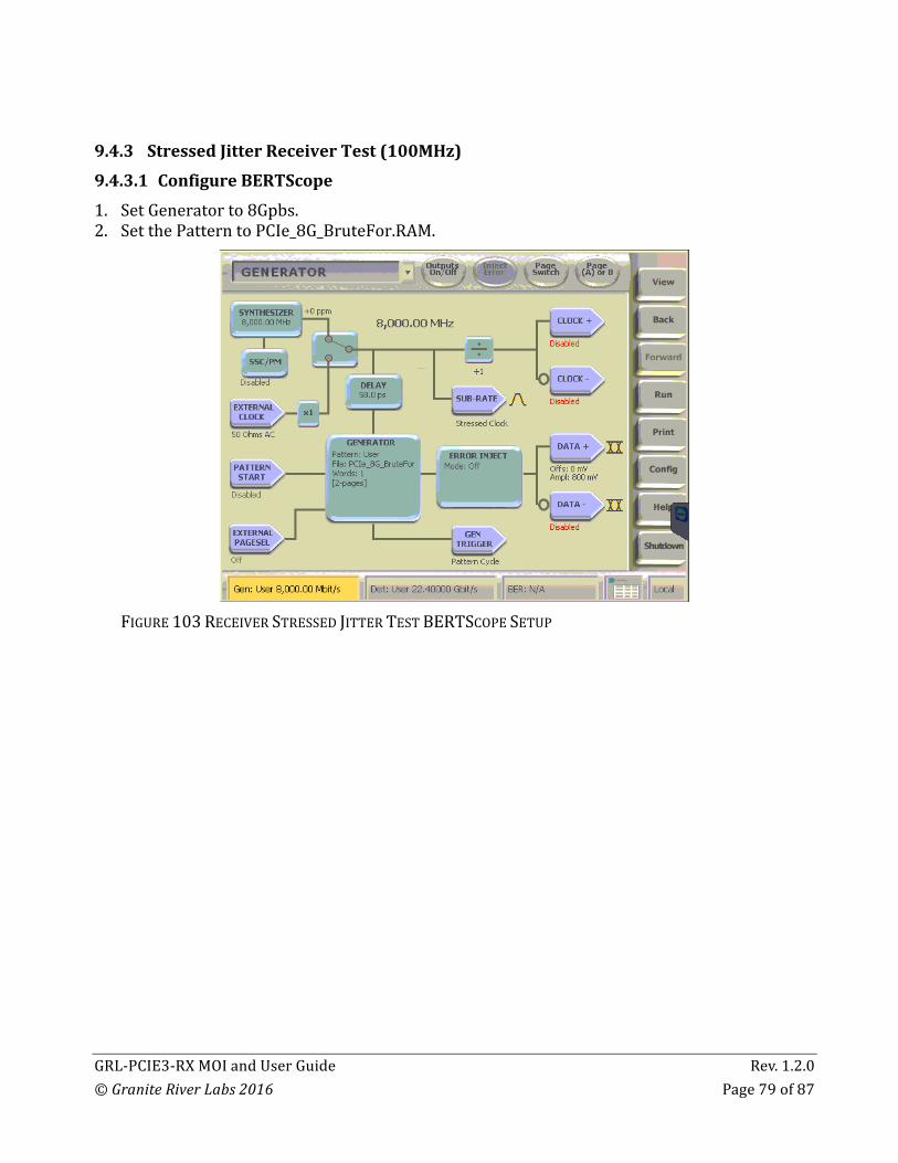
9.4.3 StressedJitterReceiverTest(100MHz)9.4.3.1 ConfigureBERTScope1. SetGeneratorto8Gpbs.2. SetthePatterntoPCIe_8G_BruteFor.RAM.
FIGURE103RECEIVERSTRESSEDJITTERTESTBERTSCOPESETUP
GRL-PCIE3-RXMOIandUserGuide Rev.1.2.0©GraniteRiverLabs2016 Page80of87
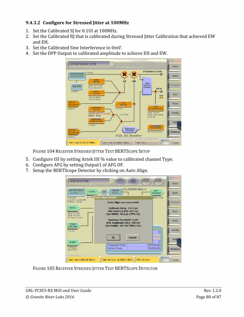
9.4.3.2 ConfigureforStressedJitterat100MHz1. SettheCalibratedSJfor0.1UIat100MHz.2. SettheCalibratedRJthatiscalibratedduringStressedJitterCalibrationthatachievedEW
andEH.3. SettheCalibratedSineInterferenceto0mV.4. SettheDPPOutputtocalibratedamplitudetoachieveEHandEW.
FIGURE104RECEIVERSTRESSEDJITTERTESTBERTSCOPESETUP
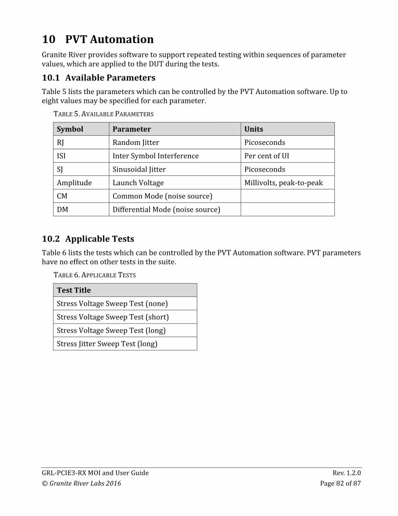
5. ConfigureISIbysettingArtekISI%valuetocalibratedchannelType.6. ConfigureAFGbysettingOutput1ofAFGOF.7. SetuptheBERTScopeDetectorbyclickingonAutoAlign.
FIGURE105RECEIVERSTRESSEDJITTERTESTBERTSCOPEDETECTOR

GRL-PCIE3-RXMOIandUserGuide Rev.1.2.0©GraniteRiverLabs2016 Page81of87
9.4.3.3 BitErrorRateTest1. WiththeDUTinloopbackmode,andBERTScopesynchronizewithpattern.2. Compliancetestmaybegin.3. ClicktheResetResult.4. ClicktheRUN.5. LettheDetectorRun,stopwhentheBITsismorethan1xE12.6. ReadtheErrorvalue.7. ItisPassiferroris0.
FIGURE106RECEIVERSTRESSEDJITTERPERFORMBERTEST
GRL-PCIE3-RXMOIandUserGuide Rev.1.2.0©GraniteRiverLabs2016 Page82of87
10 PVTAutomationGraniteRiverprovidessoftwaretosupportrepeatedtestingwithinsequencesofparametervalues,whichareappliedtotheDUTduringthetests.
10.1 AvailableParametersTable5liststheparameterswhichcanbecontrolledbythePVTAutomationsoftware.Uptoeightvaluesmaybespecifiedforeachparameter.
TABLE5.AVAILABLEPARAMETERS
Symbol Parameter Units
RJ RandomJitter Picoseconds
ISI InterSymbolInterference PercentofUI
SJ SinusoidalJitter Picoseconds
Amplitude LaunchVoltage Millivolts,peak-to-peak
CM CommonMode(noisesource)
DM DifferentialMode(noisesource)
10.2 ApplicableTestsTable6liststhetestswhichcanbecontrolledbythePVTAutomationsoftware.PVTparametershavenoeffectonothertestsinthesuite.
TABLE6.APPLICABLETESTS
TestTitle
StressVoltageSweepTest(none)
StressVoltageSweepTest(short)
StressVoltageSweepTest(long)
StressJitterSweepTest(long)

GRL-PCIE3-RXMOIandUserGuide Rev.1.2.0©GraniteRiverLabs2016 Page83of87
10.3 SettingupPVTValueSequences1. SelectthePVTConfigurationicononthetoolbar.SeeFigure107.
FIGURE107SELECTPVTCONFIGURATION
2. Addaparametertotheselectedtestbyselecting“AddCondition”.SeeFigure108,whichselects‘SJ’asthenewconditiongroup.Nodrop-downmenuofallowedparameternamesisprovided.RefertoTable5.Ashortdescriptionmaybeprovided.Thisdescription,andthenamesoftheindividualstep‘Variables’areallincludedinthetestresultsReport.
FIGURE108ADDFIRSTPVTAUTOMATIONPARAMETER
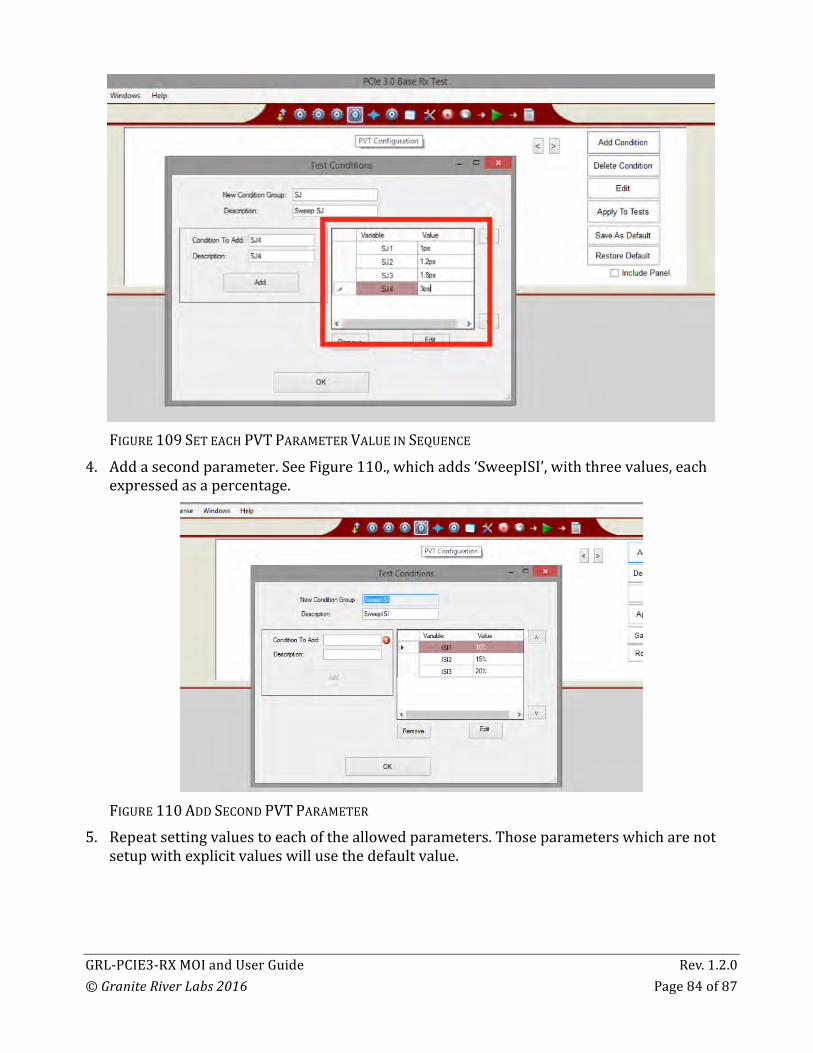
3. Enteroneormoreparametervalueforthestepsofthetestconditionsequence.Takecaretoincludethesuffixfortheunits,andtoassignvalueswhichareappropriateforthatparameteraccordingtothePCIE3specification.SeeFigure109,whichshowsfourstepsforparameter‘SJ’,named‘SJ1’,‘SJ2’,‘SJ3’and‘SJ4’,andassignedvalues1ps,1.2ps,1.8psand3ps,respectively.WhenfinishededitingtheTestConditions,clickon“OK”.Notethatindividualstepsmaybeselected,theneditedorremovedfromthelist.
GRL-PCIE3-RXMOIandUserGuide Rev.1.2.0©GraniteRiverLabs2016 Page84of87
FIGURE109SETEACHPVTPARAMETERVALUEINSEQUENCE
4. Addasecondparameter.SeeFigure110.,whichadds‘SweepISI’,withthreevalues,eachexpressedasapercentage.
FIGURE110ADDSECONDPVTPARAMETER
5. Repeatsettingvaluestoeachoftheallowedparameters.Thoseparameterswhicharenotsetupwithexplicitvalueswillusethedefaultvalue.

GRL-PCIE3-RXMOIandUserGuide Rev.1.2.0©GraniteRiverLabs2016 Page85of87
6. Fromthemenu,applythesequencesofparameterstotheselectedtests(seeFigure111andFigure112),whichbuildsa“StressTestPlan”.
FIGURE111APPLYTOTESTS
FIGURE112SELECTAPPLICABLETESTS
7. SelectthePVTteststorun(seeFigure113).
FIGURE113.SELECTPVTTESTSTORUN
GRL-PCIE3-RXMOIandUserGuide Rev.1.2.0©GraniteRiverLabs2016 Page86of87
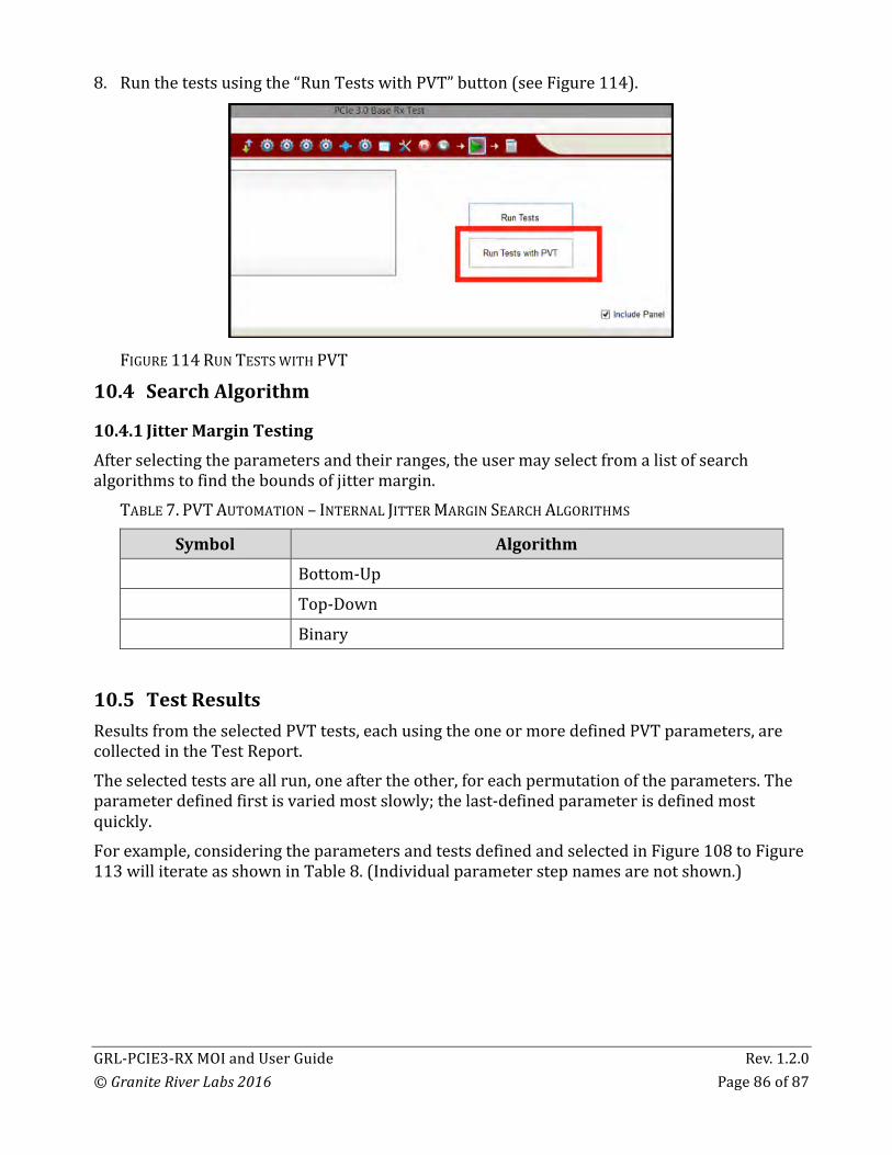
8. Runthetestsusingthe“RunTestswithPVT”button(seeFigure114).
FIGURE114RUNTESTSWITHPVT
10.4 SearchAlgorithm
10.4.1 JitterMarginTestingAfterselectingtheparametersandtheirranges,theusermayselectfromalistofsearchalgorithmstofindtheboundsofjittermargin.
TABLE7.PVTAUTOMATION–INTERNALJITTERMARGINSEARCHALGORITHMS
Symbol Algorithm
Bottom-Up
Top-Down
Binary
10.5 TestResultsResultsfromtheselectedPVTtests,eachusingtheoneormoredefinedPVTparameters,arecollectedintheTestReport.Theselectedtestsareallrun,oneaftertheother,foreachpermutationoftheparameters.Theparameterdefinedfirstisvariedmostslowly;thelast-definedparameterisdefinedmostquickly.Forexample,consideringtheparametersandtestsdefinedandselectedinFigure108toFigure113williterateasshowninTable8.(Individualparameterstepnamesarenotshown.)

GRL-PCIE3-RXMOIandUserGuide Rev.1.2.0©GraniteRiverLabs2016 Page87of87
TABLE8.PVTAUTOMATION–ITERATIONSEQUENCEEXAMPLE
Seq. SJ ISI Tests
1 1.0ps 10% All4ParameterSweepingTests
2 1.2ps 15% All4ParameterSweepingTests
3 1.8ps 20% All4ParameterSweepingTests
4 3.0ps 10% All4ParameterSweepingTests
5 1.0ps 15% All4ParameterSweepingTests
6 1.2ps 20% All4ParameterSweepingTests
7 1.8ps 10% All4ParameterSweepingTests
8 3.0ps 15% All4ParameterSweepingTests
9 1.0ps 20% All4ParameterSweepingTests
10 1.2ps 10% All4ParameterSweepingTests
11 1.8ps 15% All4ParameterSweepingTests
12 3.0ps 20% All4ParameterSweepingTests
10.6 SavingandLoadingaPVTSessionWhenusingthePVTAutomationsoftware,the“SaveAs”and“Restore”buttonsarenotused.Tosaveasession,withallofthePVTparameterinformation,thetestresults,andanywaveforms,usethe“Options”commandonthemenubar,thenthe“SaveSession”command.Toloadasessionbackintothesoftware,includingthesavedparametersettings,usethe“Options”commandonthemenubar,thenthe“LoadSession”command.Theconfigurationandsessionresultsaresavedinafilewiththeextension‘.ses’,whichisacompressedzip-stylefile,containingavarietyofinformation.
END_OF_DOCUMENT
Recommended

![GRL Research Watershed Wildfire · GRL Research Watershed Wildfire USDA-PA-ARS-GRL El Reno, OKlahoma Research Watershed WildFire Map [4/1/2017] 04 April 2017](https://img.pdfslide.us/doc/110x75/5f790a867e2fde0bff435362/grl-research-watershed-wildfire-grl-research-watershed-wildfire-usda-pa-ars-grl.jpg)