/ '.._/
•
UNIVERSITY OF CALIFORNiiA, SAN DIEGO
MARINE PHYSICAL LABORATORY
SCRIPPS INSTITUTION OF OCEANOGRAPHY
SAN DIEGO, CALIFORNIA 92152
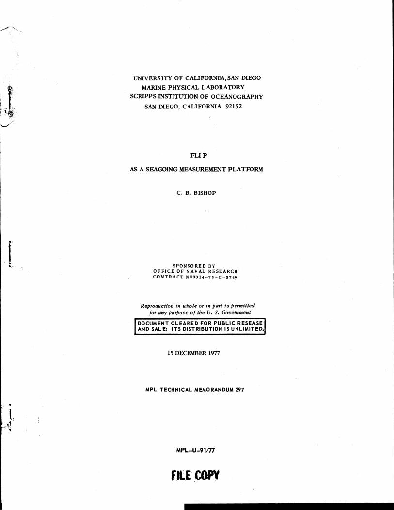
FLIP
AS A SEAGOING MEASUREMENT PLATFORM
C. B. BISHOP
SPONSORED BY OFFICE OF NAVAL RESEARCH CONTRACT NOOO 14-7 5-C-0749
Reproduction in whole or in part is permitted for any purpose of the U. S. Government
DOCUMENT CLEARED FOR PUBLIC RESEASE AND SALE: ITS DISTRIBUTION IS UNLIMITED.
15 DECEMBER 1977
MPL TECHNICAL MEMORANDUM 'J!J7
MPL-U-91m
f.ILE_COPV
•
MPL-U-91/77
UNIVERSITY OF CALIFORNIA, SAN DIEGO
MAruNEPHY~CALLABORATORY
SCRIPPS INSTITUTION OF OCEANOGRAPHY
SAN DIEGO, CALIFORNIA 92152
FLIP
AS A SEAGOING MEASUREMENT PLATFORM
C. B. BISHOP
15 DECEMBER 1977
MPL TECHNICAL MEMORANDUM '197
•
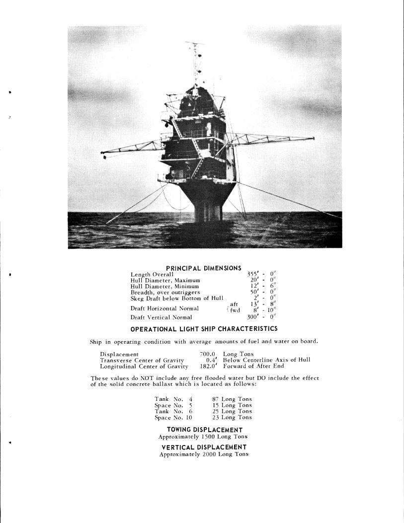
PRINCIPAL DIMENSIONS Length Overall 355' - o"
20' - o" 12' - 6" so' - o"
Hull Diameter, Maximum Hull Diameter, Minimum Breadth, over outriggers Skeg Draft below Bottom of Hull 2' - o"
13' - 8" Draft Horizontal Normal
aft {fwd 8 1 - 1011
Draft Vertical Normal 300' - o"
OPERATIONAL LIGHT SHIP CHARACTERISTICS
Ship in operating condition with average amounts of fuel and water on board.
Displacement 700.0 Long Tons Transverse Center of Gravity Longitudinal Center of Gravity
0.4' Below Centerline Axis of Hull 182.0' Forward of After End
These values do NOT include any free flooded water but DO include the effect of the solid concrete ballast which is located as follows:
Tank No. 4 Space No. 5 Tank No. 6 Space No. 10
87 Long Tons 15 Long Tons 25 Long Tons 23 Long Tons
TOWING DISPLACEMENT Approximately 1500 Long Tons
VERTICAL DISPLACEMENT Approximately 2000 Long Tons
FLIP AS A SEAGOING MEASUREMENT PLATFORM
c. B. Bishop
University of California, San Diego Marine Physical Laboratory of the
Scripps Institution of Oceanography San Diego, California 92152
Abstract
A description of the characteristics,
employment and potential of the Research
Platform FLIP. FLIP, i. e. , FLoating
Platform, designed as a Instrument
super-stable open-sea free-floating
platform, provides a unique and effective
facility for research in the field of
physical oceanography primarily
underwater acoustics.
MPL-U-91/ 77 MPL TM 297
I. PURPOSE
The purpose of this report is to provide potential users of the
Research Platform FLIP with information to assist them in the formulation
of initial plans for its use. As plans develop, arrangements can be
made to obtain more detailed information from the Officer-in-Charge FLIP
and from appropriate members of the Marine Physical Laboratory staff.
II. PAST OPERATIONS
FLIP was built as a platform to support the investigations of
acoustic fluctuations conducted by the Marine Physical Laboratory. In
addition to this research, a number of other programs have taken advantage
of its unique characteristics. The studies include:
acoustic propagation
ambient noise
storm generated waves
seismic anisotropy
sea surface radar backscatter
sea surface acoustic backscatter
near surface temperature profiling
hull arrays vertical array
vertical array DIMUS array
various sensors
acoustic receivers
radar
hull arrays
hull thermisters
2
F. H. Fisher G. B. Morris
G. B. Morris v. c. Anderson
w. H. Munk
R. Raitt G. Shor
Lincoln Lab
S. McConnell APL/UW
J. Northrop F. H. Fisher
internal waves - temp- thermister lines erature profiling
internal waves - acoustic HF sonar layers
biological scattering HF sonar
high resolution bottom HF sonar profiling, acoustic layering
scatterer distributions horizontal array
air-sea interaction various sensors
sonobuoy tests
R. R.
R.
R. P.
F.
G.
R. c.
T.
MPL-U-91/77 MPL TM 297
L. Zalkan Pinkel
Pinkel
Pinkel Greenblatt
H. Fisher
T. Kaye
Davis, c. Gibson Friehe
Stixrud, NOSC
In addition, FLIP has operated as a sonar training platform for
Navy ships and aircraft, by using its hull as an acoustic reflector and by
radiating signals from a suspended transducer. (Reference 1) It
has also demonstrated low self-noise, and capability for measuring
acoustic noise radiated from a Navy surface ship. (Reference 2)
FLIP has spent some 1000 days at sea and has completed the
transition from horizontal to vertical and return more than 200 times.
Although designed with an endurance capability of two weeks
at sea, an operation of 45 days duration was scheduled and completed
in late 1963. During this operation in the North Pacific 1800 miles
from San Diego, FLIP was vertical for 27 consecutive days. Stores,
fuel and water were transferred by highline once during this period.
Ten men subsisted on board with relative comfort during the entire
operation. Towing time to station was 10 days, the return trip 8 days.
3
MPL-U-91/77 MPL TM 297
While on station, gale force winds and seas were practically
continuous and offered ample opportunity to evaluate FLIP's capabilities.
Maximum vertical oscillation was measured at less than 1/10 wave
height. Seas to 35' were encountered during this period. Since this
operation there have been several deployments to Hawaiian waters.
From late March to early August 1969 FLIP operated in the Caribbean
as a valuable unit supporting micrometeorological work in the huge
BOMEX operation off Barbados and then north to Puerto Rico collecting
more data on sonar bearing accuracy.
As operating experience and confidence have been gained, it is
no longer considered necessary to keep a vessel in attendance while
on station. Tugs have been released for periods of over four weeks
when it is desired to keep the local noise level to a minimum and/or
reduce expenses. •
III. GENERAL DESCRIPTION
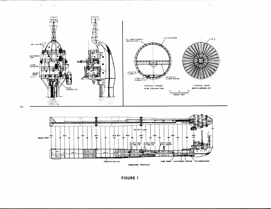
Figure 1 shows the general arrangement and inboard profile of
FLIP in the horizontal towing position, and to a larger scale, two views
of the upper portion of the platform in the vertical or operating position,
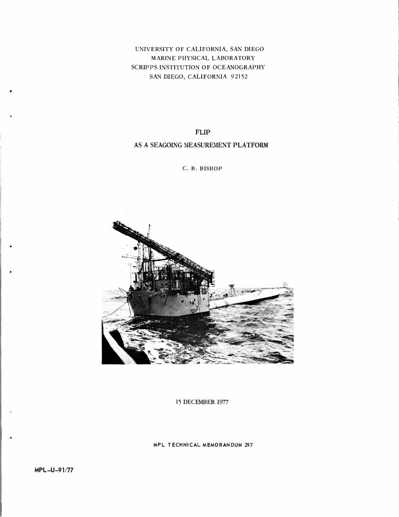
FLIP is essentially a long, slender tubular hull 20 feet in diameter
for almost half its length from the stern, and tapering to a cylinder
12-1/2 feet in diameter as the bow is approached. The bow, itself,
of a full, deep spoon type, is unconventional principally in the fact
that it terminates abruptly at the point where it joins the cylindrical
hull some 40 feet from the forward end. Length overall is 355 feet.
FLIP is designed to tow in a horizontal attitude ballasted with water
so as to float at approximately half-diameter with a draft of about
10 feet. Arriving at the scene of a research operation, controlled
4
VI
ELECTRONICS LABS
LIVING QUARTERS
r
=
ENGINE {
ROOM··~
Hili IV
I 111 BHD SCALE: FEET 0 " 40
I f , ... ,., I TAIIII 1-1
...____,
0 ~ T 0 :: \11,
11 I BHD
Ill Ill 1111
I TANK 2
Jli}ANK 3-T lin!' m:, •• .,.mJil
I 120
I , ... Jr. 4
I /
0
0 ;
All LONGITUOINALS ARE 6X4X518"l
4 X 112" FB FLANGE
-
TYPICAL FRAME
FA 80 -LOOKING FWD
- -
X 3/B"Il WEB
0 5 10
SCALE: FEET
TYPICAL BHD
BHD 70·LOOIC.ING AFT
.
~ ~ I
" -71
lJ.ll oJcK !LAL .. 1"" :n
I ~~-p. BHD BHD BHD BHD
TIT 140 110 1111 2110 210 ZIO 300 315
I I I I bm ~
t3) AIR FLASKS (3) AIR FLASKS 121 AIR FLASKS
'AI AND(" I ~~AND(" 381R LENGTH
lin. 11 •Jill'
IT Ill ill I II I IWII6IJ~~~..,J-T TANiti·T ~ • •c .~.)}
rri-T~ TANK I ~· TAfitltl II ~ o• !~11:1-• TAN. 1·1 ~
I \ CONCRETE BALLAST PUMP ROOM• ELECTRONICS "BERTHS "AIR COMPRESSORS
INBOARD PROFILE
FIGURE 1
MPL-U-91/77 MPL TM 297
flooding of tanks will cause the platform to raise her bow and drop
her stern until she floats in a vertical position drawing some 300 feet
of water with the bow rising 55 feet into the air. As shown in Figure 1,
in this position there are four operating levels in the bow section -
a machinery space, living quarters, an electronics space and crews quarters
in ascending order. There is a boarding platform at the lowest level
and larger, external working and observation platforms at the two
upper laboratory levels - the platform at the Engine Room level is also
the location of the operating station from which the flipping maneuver
is controlled. The spaces in the hull proper are essentially
tanks flooded with water or held empty or partially full as
necessary to give the desired draft and stability characteristics. The
uppermost tank has been converted to space for auxiliary machinery
and additional berthing.
Detailed description of the platform and of its operation are
contained in reference (3).
IV. CHARACTERISTICS
FLIP can be towed at speeds up to 8 knots, depending on the
towship horsepower, and rides comfortably in most sea conditions. The
concrete in the keel gives added stability and reduces rolling
tendencies.
During transition to the vertical, which takes about 30 minutes,
all personnel are outside and share the unique experience of trans
formation from a horizontal barge to a vertical spar buoy. Detailed
discussion of this evolution is contained in reference (4).
6
MPL-U-91/77 MPL TM 297
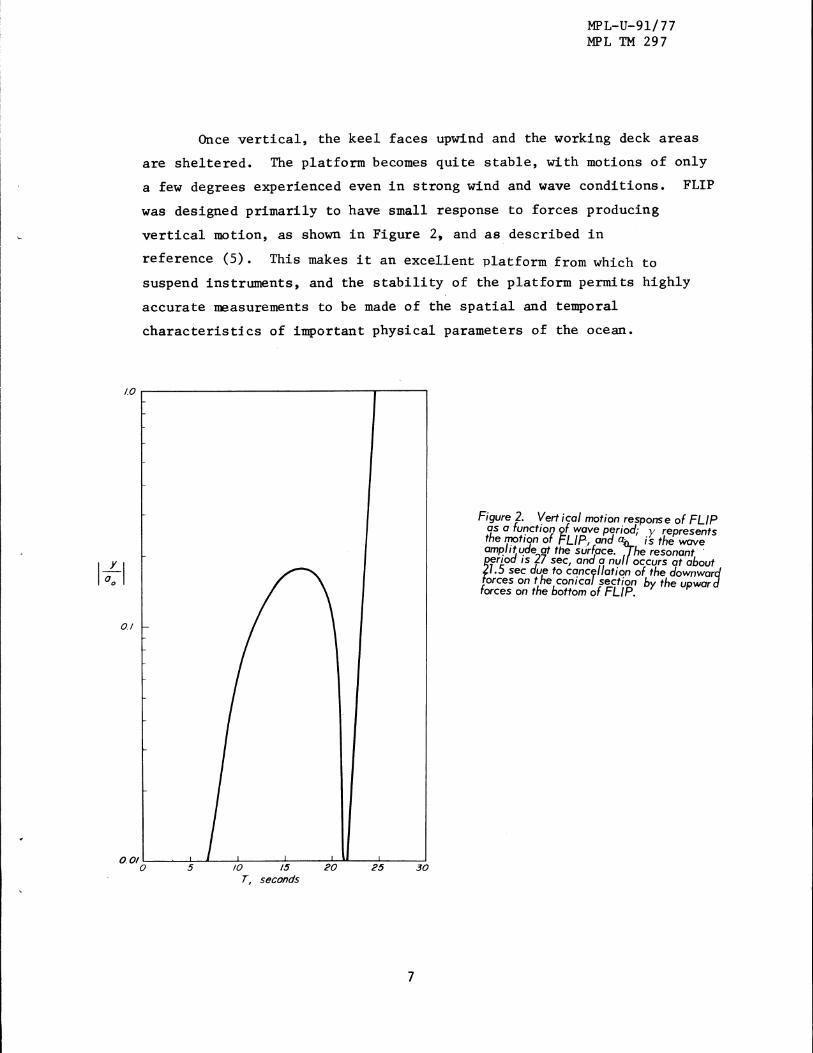
Once vertical, the keel faces upwipd and the working deck areas
are sheltered. The platform becomes quite stable, with motions of only
a few degrees experienced even in strong wind and wave conditions. FLIP
was designed primarily to have small response to forces producing
vertical motion, as shown in Figure 2, and as described in
reference (5). This makes it an excellent platform from which to
suspend instruments, and the stability of the platform permits highly
accurate measurements to be made of the spatial and temporal
characteristics of important physical parameters of the ocean.
lOr-----------------------------,------,
1~1
0.1
0 · 01 0~----~5_....---,-,.':o,----~,5=-----2~o::-"'----:-25'::-----3--'o T, seconds
7
Figure 2. Vertical motion response of FLIP ahs a fur:rction 2f wave period; y represents t e mot1qn of FLIP, and); is the wave amplit~e at the surface. he resonant · tenod IS 27 sec, and a nul occurs at about 1.5 sec due to canc~llation of the downward orces on the conical section by the upward
forces on the bottom of FLIP.
MPL-U- 91/77 MPL TM 297
Transducer and hydrophone arrays can be mounted at various locations
along the 300' depth of the submerged hull for acoustic studies in
the upper levels of the ocean. Similar measurements can be made
from sensors mounted on the bottom of FLIP, looking vertically down to
the sea floor. Vertical long-line arrays can be lowered from FLIP
to position hydrophones at chosen depths throughout the entire water
column. These arrays can be deployed and retrieved at will to
facilitate changes in experimental setups.
Various measuring devices can be deployed from one or more of
the three 60'-75' booms which can be swung out from FLIP's upper deck
structure when vertical. These include current sensors, temperature
profilers and wave height measurers.
Meterological instruments, radar and optical devices can be
mounted topside for sea surface and atmospheric measurements. Antenna
height of 85 feet is available using the hydraulically operated mast.
FLIP can be allowed to drift or it can be secured in a three
point moor in depths to 3000 fathoms. In the latter case, it will
hold position within a few hundreds of yards. Mooring and unmooring
require about 12 hours of daylight each, and the services of a towship
with 1000 sq. ft. of deck space to carry the mooring lines and
ground tackle.
Commercial tugs are used for towing when Navy fleet tugs are
not available.
In the drifting mode, FLIP is an excellent platform for making
measurements of the properties of the surrounding water mass, and
their fluctuations with time.
8
.•
MPL-U-91/77 MPL TM 297
In the moored mode, FLIP provides an ideal platform for
conducting time-series investigations from a fixed location at
sea, including measurements of energy radiated from ships and
submarines.
Based in San Diego, the home port of nearly all types of Fleet
units, FLIP has all-year, good weather access to deep water with
short travel times. MPL can provide fabrication, installation, and
checkout support for test equipment.
V. AUXILIARY MACHINERY
A. Diesel Generators
Power to all electrically operated machinery is obtained from
two 150 kw, 440 volt, 3-phase, a.c. generators directly driven by
Caterpillar Model D334TC diesel engines; engine speed is 1800 rpm.
Power is delivered to the switchboard through generator-mounted
automatic voltage regulators. Engines are trunnion-mounted
for operation in either horizontal or vertical positions, and are
mounted on air ride cushions to reduce sound transmission.
A 40 kw, GM 3-53 diesel generator set is mounted on trunnions,
adjacent to the main switchboard. This set is used mainly for
housekeeping but is capable of maintaining the normal research load
as well. When orientation or air compression is required, one
of the larger engines must be utilized. Usually the small generator
is left on the research circuits in order to maintain finer voltage
and frequency control.
9
MPL-U-91/ 77 MPL TM 297
B. Compressed Air
The Ingersoll-Rand Model H25M Circular Space Air Compressors
are located between frames 300 and 31S. These are two-stage
air-cooled compressors and are rated for 250 psi, and will automatically
shut off at 250 psi. A constant watch is maintained while charging.
About 5 hours are required to charge all banks from 100 to 250 psi,
using both compressors. These machines are trunnion-mounted for
operation in either horizontal or vertical attitudes.
There are 8 air storage flasks in 3 banks which store a little
more than 3000 cu.ft. of air at a maximum pressure of 250 psi. No. 1
bank, three bottles, is located in No. 7-T and 7-B ballast tank;
No. 2 bank, three bottles, is in No. 8-BT; bank 3, consisting of two
larger bottles, is in No. 9-T ballast tank. Air from the bottles
in each tank is piped to a common riser which terminates at the control
platform. Thus, there are three risers and three cut-in valves at
the manifold. They are plainly marked and make it possible to utilize .
any combination of banks for air service. Each bank may be isolated
from the rest by an individual stop valve at the operating manifold.
Each bottle has a 3/4" drain plug at the aft end bottom.
A low pressure blower is used to void residual water after
returning to the horizontal attitude. This blower is located in tank
No. 10 at frame 312 on the partial flat and is piped directly to the
high and low pressure manifolds. Blower control is also at the
control station.
C. Fresh Water
Fresh water is carried in a 1500 gallon tank, and replenished
daily by a 20 gal/hour distiller.
10
4
\.
•
D. Electrical Distribution
.MPL-U-91/ 77 MPL 1M 297
The main switchboard is located in the forward port corner of
the engineering space. In general, the board is split into two
sections, port and starboard. Shore power is on the starboard bus.
Each diesel generator supplies its side of the board, and distribution
switches are duplicated so that all lights and electrically operated
machinery have a source on each side and from any engine. No
provision is made for paralleling generators.
Interlocks are provided so that both sources cannot be applied
to any circuit simultaneously. Breakers are individually marked.
Power to the board is 440 volt, 3-phase, a.c.; from the board 440
volts and through transformers 110 volts for lighting, etc. 220-volt
power both single and three-phase is available in the engine room.
An additional 110 volt circuit has been added in order to
supply the electronics laboratory with separate power whenever
uninterrupted voltage and exact frequency regulation is required beyond
the capacity of the small generator. This circuit is fed off the
main board through a transformer bank mounted in No. 10 tank under
the Engine Room access landing.
E. Laboratories
The upper laboratory, created by the deck house addition, houses
ship's Radar, LORAN, radio transceivers, orientation controls, anemo
meters, fathometer and space for one frame of research instruments
(4~' x 2~' x 6'). Entry for instrument cables is located in the
horizontal overhead. Communications are provided by either VHF, or
HF-SSB transceivers for voice radio and by UQC for underwater telephone.
11
MPL-U-91/ 77 MPL TM 297
The main laboratory located adjacent to the upper laboratory
when vertical, below when horizontal, provides space for 4 instrument
frames. These frames (6' x 2~' x 6') are provided with hold down
fittings and electrical outlets at each location, and accommodate
3 standard relay racks side-by-side.
Normally, racks are instrumented in the shoreside laboratories,
shop tested, and loaded on board FLIP thru the large hatches provided
in the horizontal overhead of the labs while the platform is horizontal.
F. Orientation
A hydraulically operated orientation system has been installed
in order to maintain headings in the vertical position. This system
consists of two separate hydraulic units each operated by 20 hp
motors driving A-end pumps which in turn drive B-ends directly
shafted to propellers which are mounted on the hull at the 100-foot
elevation.
The motors and A-ends are mounted in the pump room and are
controlled by switches and valves on a control stand located in the
electronics laboratory adjacent the entrance.
An additional component for this system is the MK 18 gyro
compass mounted on gimbals in tank 10. This compass drives two
repeaters, one located at the orientation control platform for use
in either H or V position. A third repeater is located in the auto
matic control system, which provides either manual or automatic
orientation.
12
..
VI. HABITABILITY
MPL-U-91/ 77 MPL TM 297
The space between frames 313-1/2 and 331-2/3 is divided into
four compartments and fitted out as (1) galley and messing, (2) ward
room, (3) berthing and (4) head.
In the horizontal position the four compartments are two over
two. In the vertical position the four become adjacent rooms on
one level.
1. The galley includes a deep freeze, refrigerator, four
element range, oven, and sink. Working areas are adjacent to the deep
freeze and range. All the above is trunnion-mounted in one large
frame so that all units are usable in either position.
A system of plywood shelves and cabinets have been
attached near the freezer, range and sink so that they too are always
upright and usable. A mess table and folding chairs are provided for
seating five. These must be folded and stored during flipping operations.
2. The wardroom, directly under the galley in the hori
zontal position but becoming adjacent when vertical, consists of a
two-position transom, a table capable of seating five, and book and
magazine racks. The table and chairs are folded and stored for
flipping but the transom is rigged so that the seat becomes the back
and vice versa for the two operating positions. Lockers for provision
storage are located behind and under the transom cushions.
3. The berthing compartment is adjacent the wardroom
and contains four trunnion-mounted bunks along with lockers for
occupants, linen lockers and ventilation fans. Access from the bunk
room to the head and wardroom is provided in the vertical position
but only to the wardroom while horizontal.
13
MPL-U-91/ 77 MPL TM 297
Berthing facilities for crew and junior scientific
personnel are located in the crew's quarters forward and in a portion
of the tank 10 conversion, and for the ship's officers in a cabin which
contains two bunks, a shower (horizontal) and head.
4. The washroom and head is located over the starboard
end of the berthing compartment in the horizontal position, adjacent
when vertical. There are two wash basins - one for vertical, one for
horizontal located at 90° angles, a shower usable only in the vertical
position, the hot water heater which operates in either position, the
medical locker, the water closet on telecoping standards and attached
to a swivel-jointed drainpipe, plus other minor items.
5. Access to all these compartments is by "L" shaped
doors or in the horizontal position by ladders. Food storage lockers
built along the outboard bulkheads are fitted with small compart
ments to prevent spilling of contents.
In addition a large, trunnion-mounted refrigerator
is installed topside on the weather deck. Additional bulk dry storage
is located adjacent the engine room in tank No. 10.
6. A 7~ ton chilled water air conditioning unit has
been installed in the pump room. This is a closed system which supplies
chilled water to evaporators in all compartments except the engine
and Air Compressor rooms. Each compartment has its own thermostat
for individual temperature control.
The entire hull from frame 270 forward has been
insulated to enhance performance of the air conditioning system.
14
•
'
1111
•
VII. ARRANGEMENTS
MPL-U-91/77 MPL 1M 297
FLIP is a U.S. Navy owned seagoing research platform which is
operated by the Marine Physical Laboratory of the Scripps Institution
of Oceanography, University of California, San Diego, primarily in
support of research funded by the Office of Naval Research. It is
manned and maintained by the SIO Marine Superintendent, and scheduled
by the Director of the Marine Physical Laboratory.
With berthing available for 10 scientific party personnel,
different research groups are able to conduct experiments on FLIP
on the same cruise when their experimental procedures are compatible
for simultaneous or time-sharing operations. This capability can
result in reduced costs for individual projects.
Arrangements for its use can be made by contacting:
Mr. Charles B. Bishop
Assistant Director
Marine Physical Laboratory
Scripps Institution of Oceanography
University of California, San Diego
San Diego, California 92152
Telephone: (714) 452-2303 or Autovon 933-7176
15
MPL-U-91/77 MPL TM 297
REFERENCES
(1) C. B. Bishop and F. H. Fisher, FLIP Aids Fleet Training,
Naval Research Reviews, May 1975.
(2) C. B. Bishop and G. B. Morris, FLIP as a Platform for Measuring
Radiated Noise of Surface Ships (U}, Marine Physical Laboratory
Technical Memorandum 286, 18 January 1977 (MPL-U-6/77).
(3) E. D. Bronson and L. R. Glosten, FLIP - FLoating Instrument
Platform, SIO Reference 73-30, 15 November 1973.
(4) F. H. Fisher and F. N. Spiess, FLIP - Floating Instrument
Platform, J. Acoust. Soc. Am., 35, No. 10, pp. 1633-1644,
October 1963.
(5). Philip Rudnick, MOtion of a Large Spar Buoy in Sea Waves,
Journal of Ship Research, 11, No. 4, pp. 257-267, December
1967.
•
Recommended