COMP371 COMPUTER GRAPHICS
SESSION 2INTRODUCTION TO COMPUTER GRAPHICS
Lecture Overview• Introduction to Computer Graphics• Graphics pipeline• OpenGL API• Primitives: lines, polygons• Attributes: color• Code Example
2
What is OpenGL?• Low-level graphics library (API) for 2D/3D interactive
graphics• Originated from SGI’s GL in 1992• Current version 4.5 (2014) • Future version 5.0 or Vulkan?
• Managed by Khronos Group (non-profit consortium)• API is governed by Architecture Review Board (part of
Khronos)• Used in broadcasting, CAD/CAM/CAE, entertainment,
medical imaging, and virtual reality to produce and display incredibly compelling 2D and 3D graphics.
3
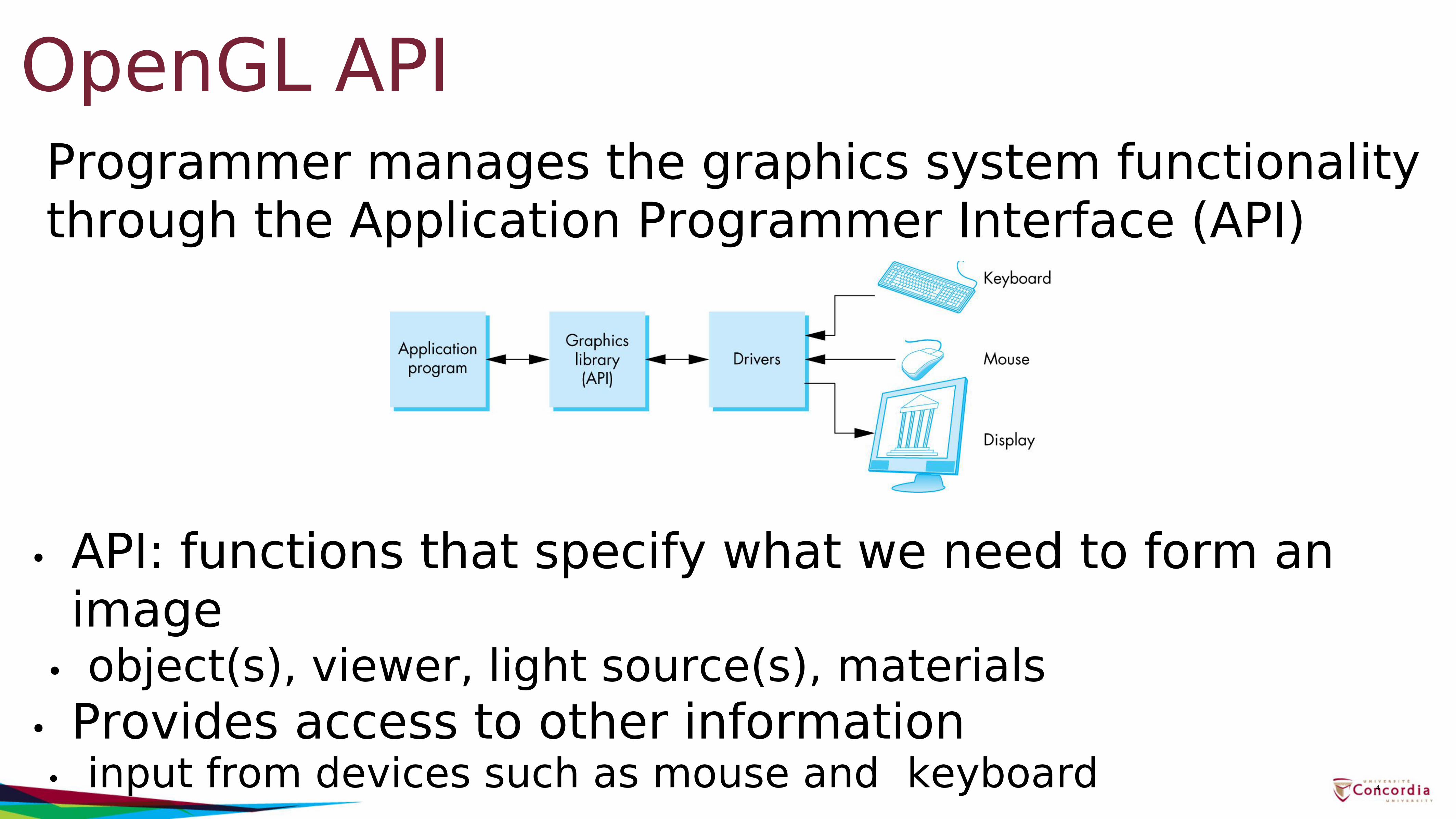
Programmer manages the graphics system functionality through the Application Programmer Interface (API)
• API: functions that specify what we need to form an image
• object(s), viewer, light source(s), materials• Provides access to other information
• input from devices such as mouse and keyboard
OpenGL API
4
OpenGL is cross-platform• Available for Windows, Linux, Mac
• A freeware OpenGL implementation is also available on Linux called Mesa
• Same code will work on different OSes• most of the time with no modifications!
5
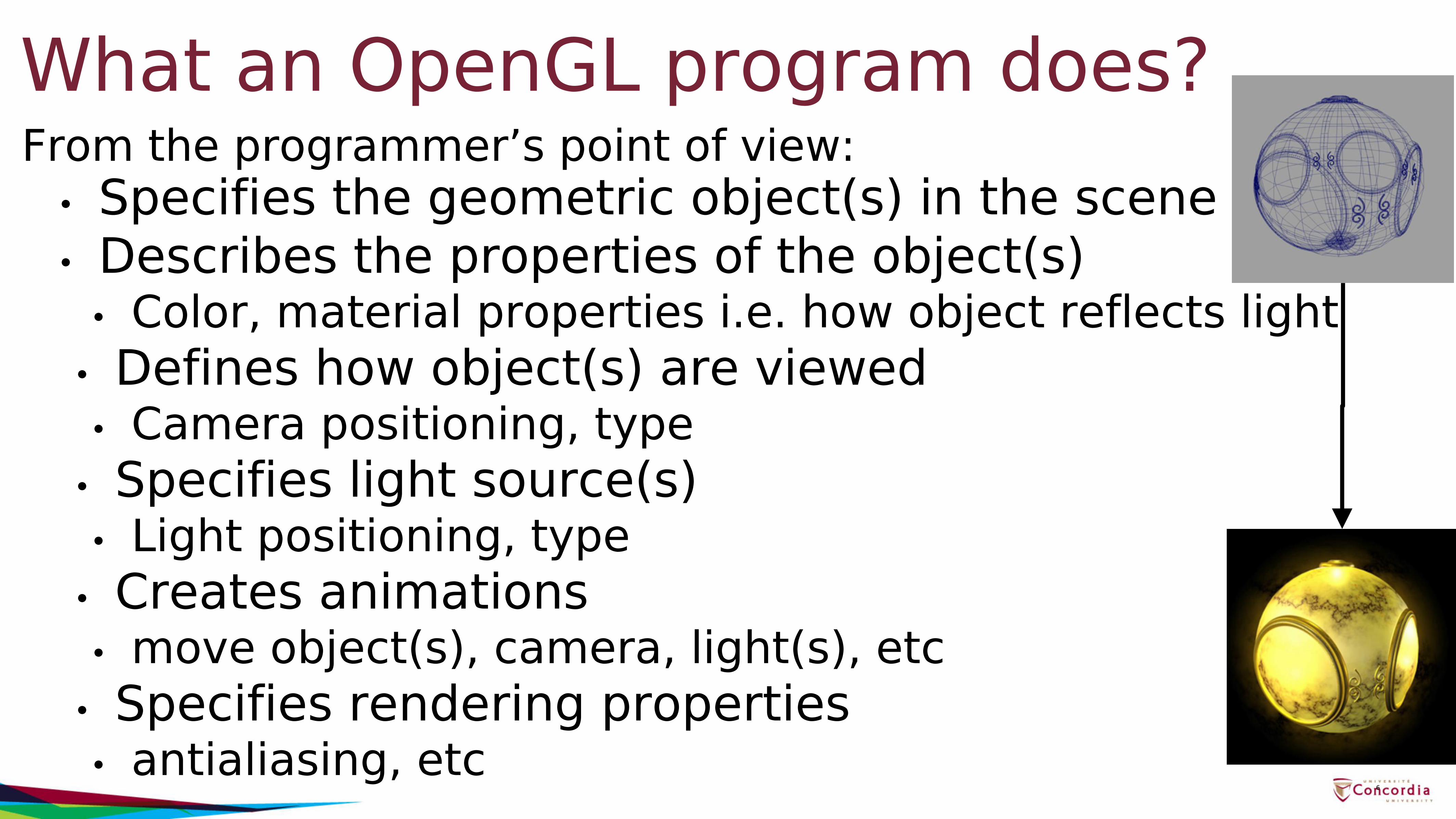
What an OpenGL program does?• Specifies the geometric object(s) in the scene• Describes the properties of the object(s)
• Color, material properties i.e. how object reflects light• Defines how object(s) are viewed• Camera positioning, type
• Specifies light source(s)• Light positioning, type
• Creates animations• move object(s), camera, light(s), etc
• Specifies rendering properties• antialiasing, etc
6
From the programmer’s point of view:
How OpenGL works?OpenGL is a state machine• You give it orders to set the current state of any one
of its internal variables, or to query for its current status
• State variables: color, camera position, light position, material properties, etc
• The current state persists until set to new values by the program
• Example: once we set a color, that color remains the current color until it is changed through a color-altering function
7
Library Organization
8
OpenGL (GL) - core graphics• function names begin with the letters glOpenGL Framework Library (GLFW)- provides programmers with the ability to create and manage windows and OpenGL contexts, as well as handling of input devices and events.• function names begin with the letters glfwOpenGL Extension Wrangler Library (GLEW) - provides efficient run-time mechanisms for determining which OpenGL extensions are supported on the target platform.• function names begin with the letters glew
Other libraries (some examples)• GLM – OpenGL Mathematics
• C++ math library based on the OpenGL Shading Language (GLSL) Specifications
• OGRE – Object-Oriented Graphics Rendering Engine• scene-oriented, real-time, 3D rendering engine. It is written
in C++ and is designed to make it easier to write programs that use hardware-accelerated 3D graphics.
9
Immediate-mode [up to v3.1]• Primitives are not stored in the system but rather
passed through the system for possible rendering as soon as they become available
• Each time a vertex is specified in application, it is sent to the GPU
• Creates data transfer bottleneck between CPU and GPU
• Removed since OpenGL 3.1• The scene is re-drawn for each frame
10
Retained mode [v3.1 onwards]• We want to minimize the data transfers from CPU to
GPU• Solution:• Put all vertex and attribute data in array• Send array to GPU to be rendered immediately
This is almost OK but problem is we would have to send array over each time we need another render of it
• Revised solution:• Put all vertex and attribute data in array• Send array over and store on GPU for multiple renderings
11
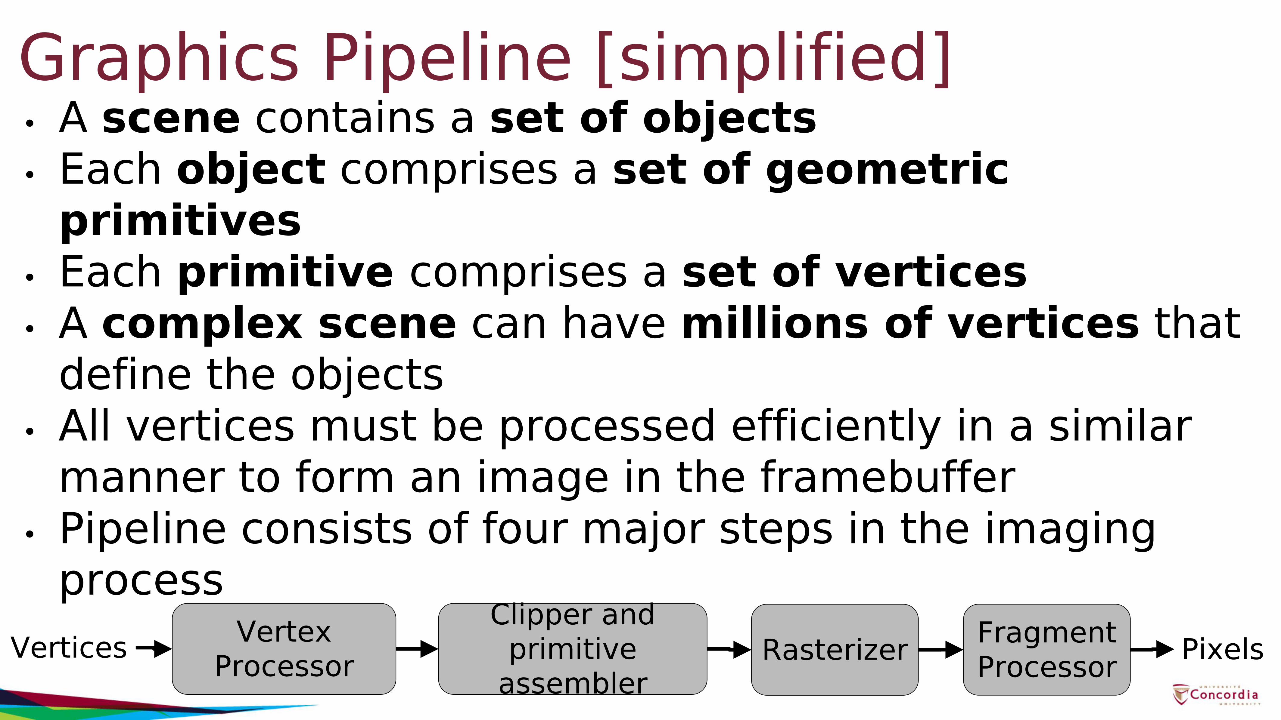
Graphics Pipeline [simplified]• A scene contains a set of objects• Each object comprises a set of geometric
primitives• Each primitive comprises a set of vertices• A complex scene can have millions of vertices that
define the objects• All vertices must be processed efficiently in a similar
manner to form an image in the framebuffer• Pipeline consists of four major steps in the imaging
processVertices Vertex
ProcessorClipper and
primitive assembler
Rasterizer Fragment Processor Pixels
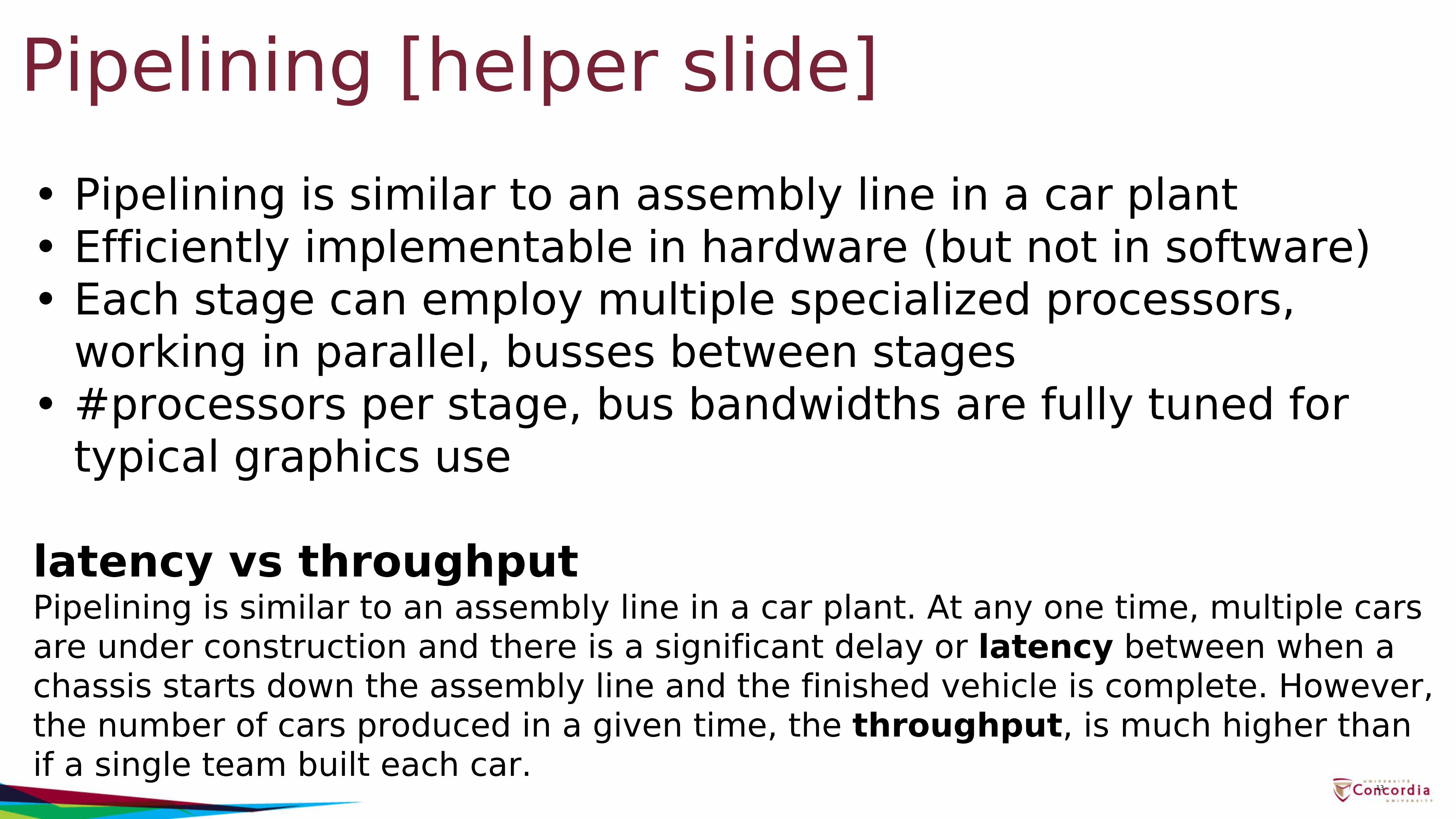
Pipelining [helper slide]• Pipelining is similar to an assembly line in a car plant• Efficiently implementable in hardware (but not in software)• Each stage can employ multiple specialized processors,
working in parallel, busses between stages• #processors per stage, bus bandwidths are fully tuned for
typical graphics use
latency vs throughputPipelining is similar to an assembly line in a car plant. At any one time, multiple cars are under construction and there is a significant delay or latency between when a chassis starts down the assembly line and the finished vehicle is complete. However, the number of cars produced in a given time, the throughput, is much higher than if a single team built each car.
13
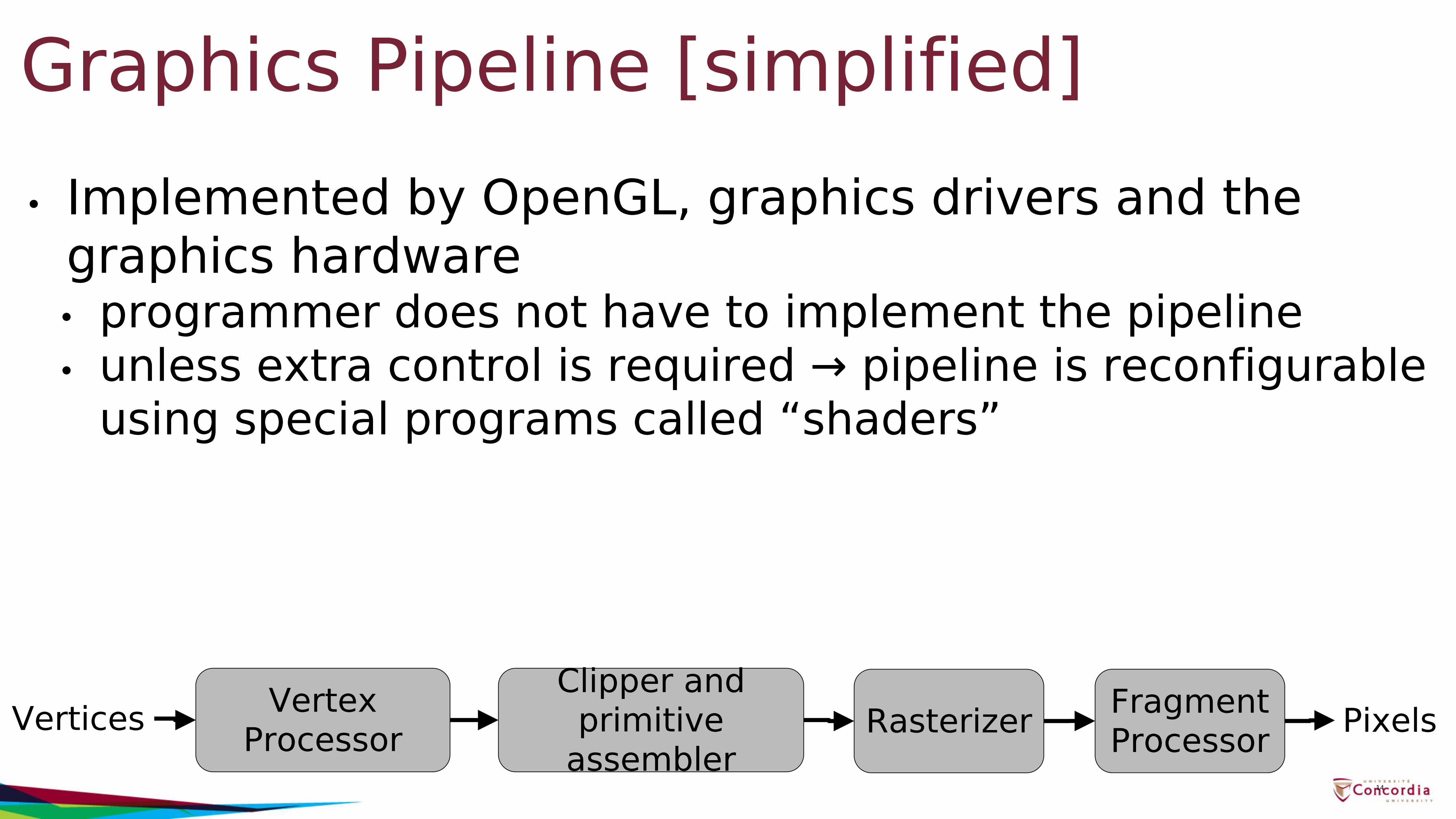
Graphics Pipeline [simplified]• Implemented by OpenGL, graphics drivers and the
graphics hardware• programmer does not have to implement the pipeline• unless extra control is required → pipeline is reconfigurable
using special programs called “shaders”
14
Vertices Vertex Processor
Clipper and primitive
assemblerRasterizer Fragment
Processor Pixels
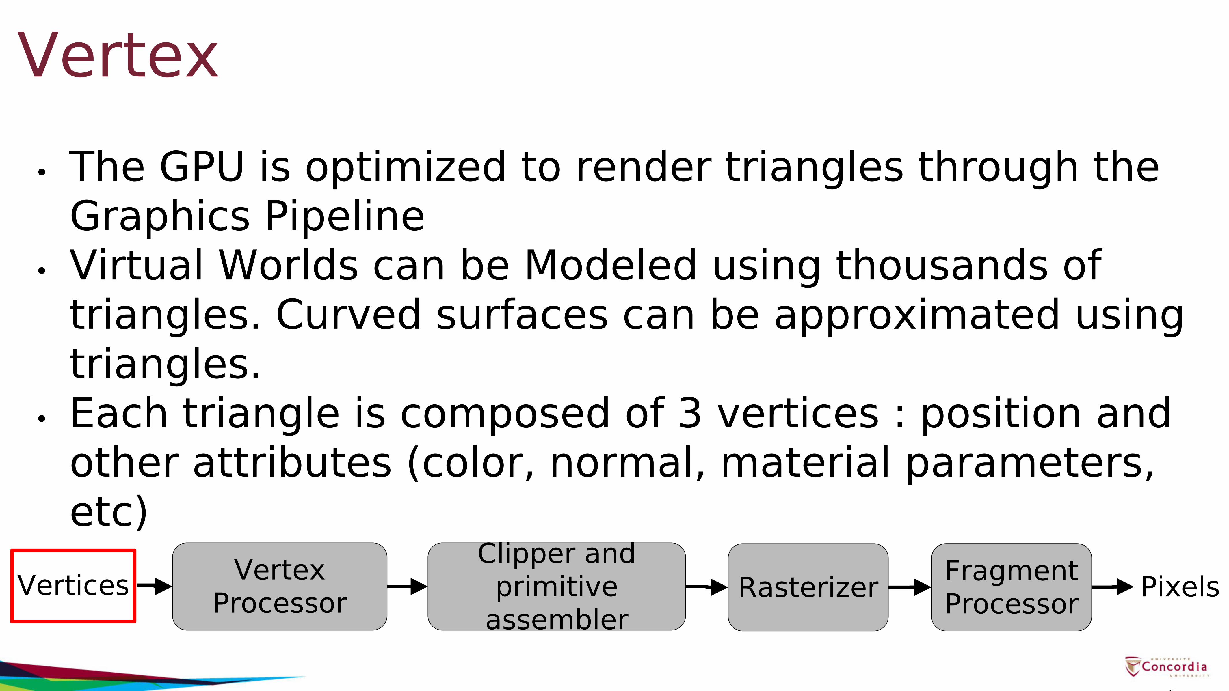
Vertex• The GPU is optimized to render triangles through the
Graphics Pipeline• Virtual Worlds can be Modeled using thousands of
triangles. Curved surfaces can be approximated using triangles.
• Each triangle is composed of 3 vertices : position and other attributes (color, normal, material parameters, etc)
15
Vertices Vertex Processor
Clipper and primitive
assemblerRasterizer Fragment
Processor Pixels
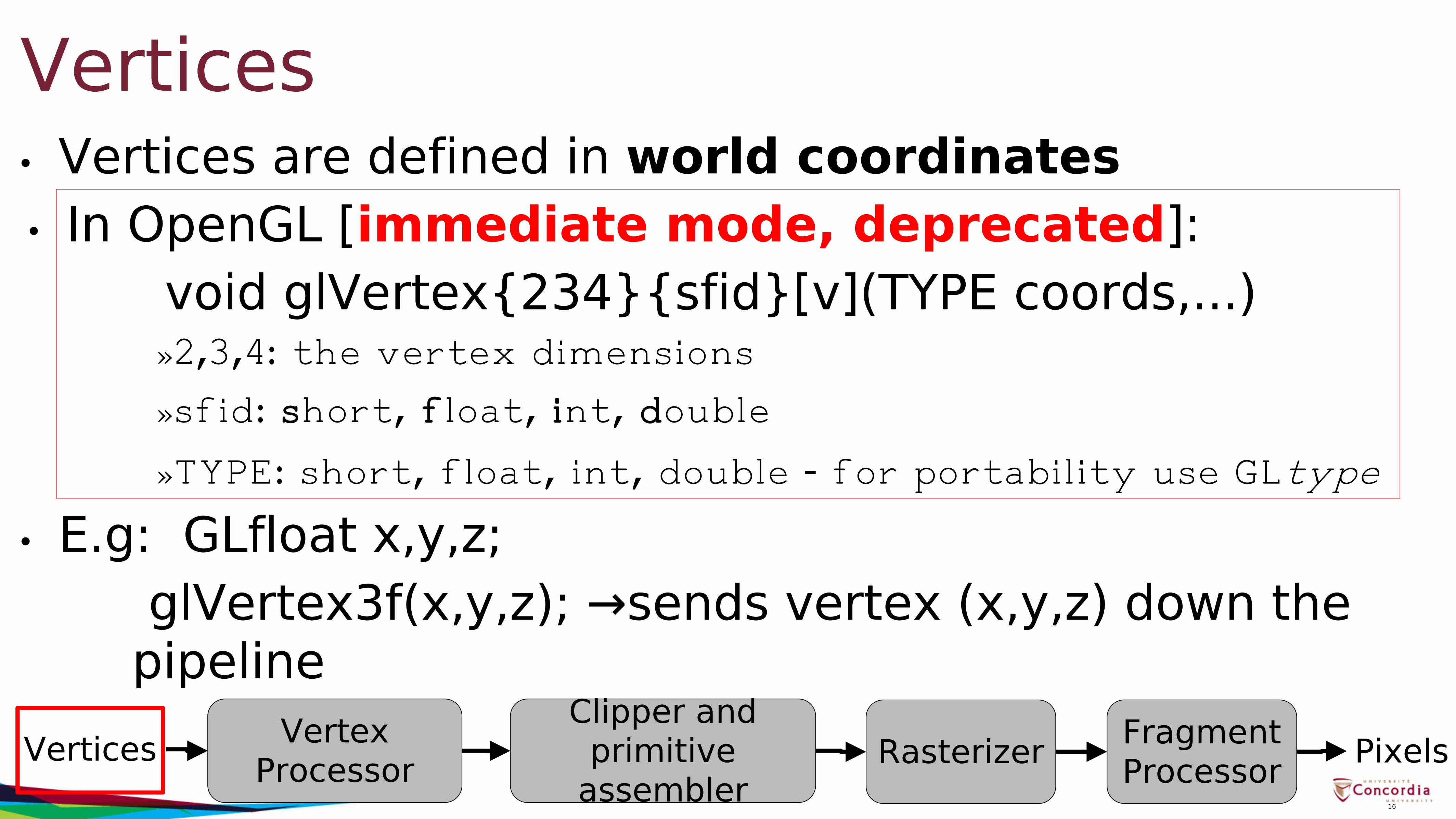
• Vertices are defined in world coordinates• In OpenGL [immediate mode, deprecated]:
void glVertex{234}{sfid}[v](TYPE coords,...)»2,3,4: the vertex dimensions
»sfid: short, float, int, double
»TYPE: short, float, int, double - for portability use GLtype
• E.g: GLfloat x,y,z;glVertex3f(x,y,z); →sends vertex (x,y,z) down the
pipeline
Vertices
16
Vertices Vertex Processor
Clipper and primitive
assemblerRasterizer Fragment
Processor Pixels
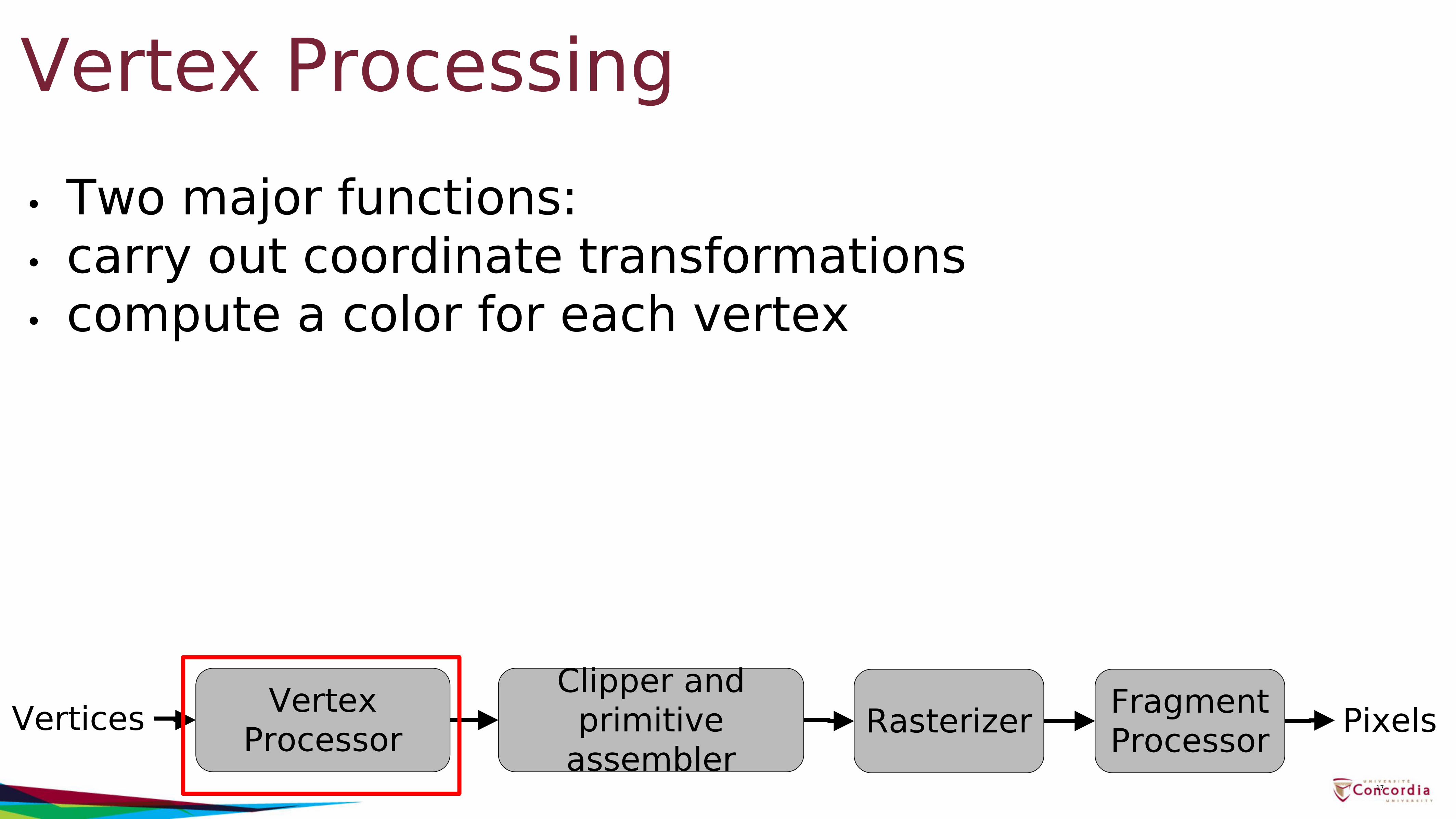
Vertex Processing• Two major functions:• carry out coordinate transformations• compute a color for each vertex
17
Vertices Vertex Processor
Clipper and primitive
assemblerRasterizer Fragment
Processor Pixels
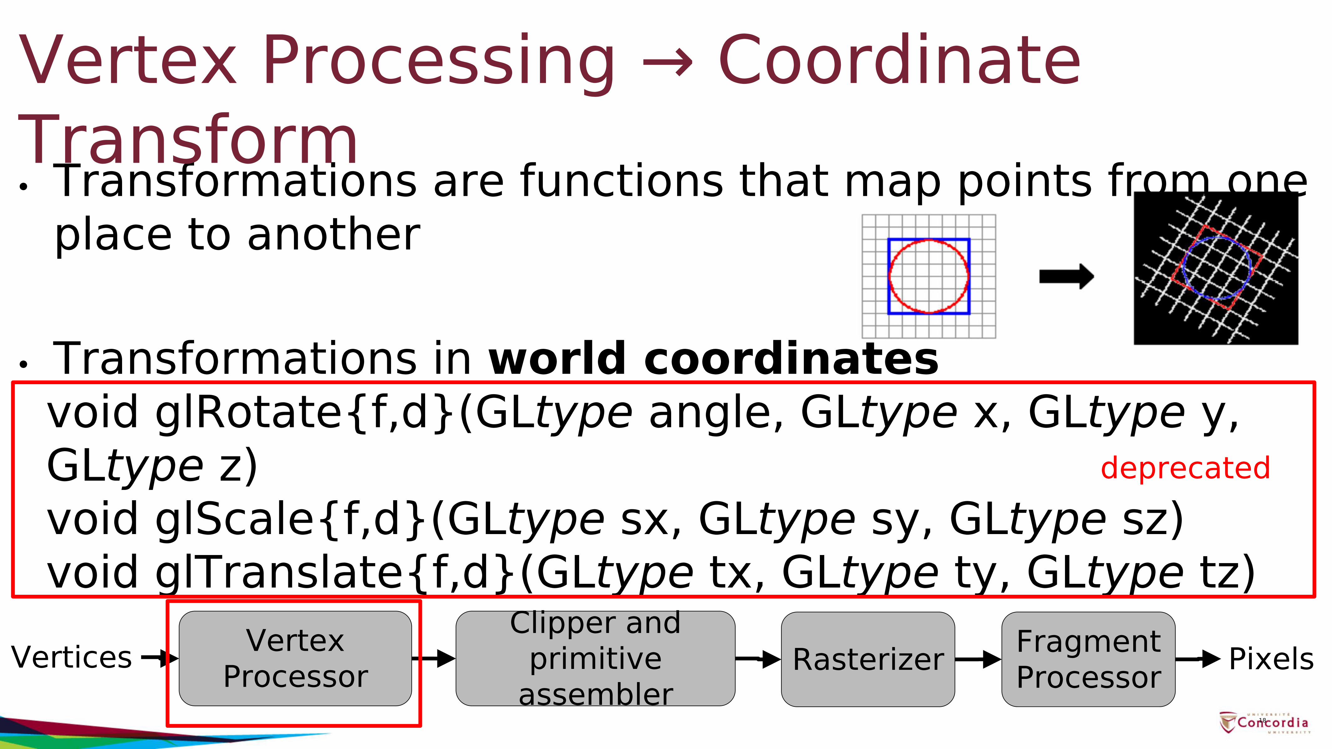
• Transformations are functions that map points from one place to another
• Transformations in world coordinatesvoid glRotate{f,d}(GLtype angle, GLtype x, GLtype y, GLtype z)void glScale{f,d}(GLtype sx, GLtype sy, GLtype sz)void glTranslate{f,d}(GLtype tx, GLtype ty, GLtype tz)
Vertex Processing → Coordinate Transform
18
Vertices Vertex Processor
Clipper and primitive
assemblerRasterizer Fragment
Processor Pixels
deprecated
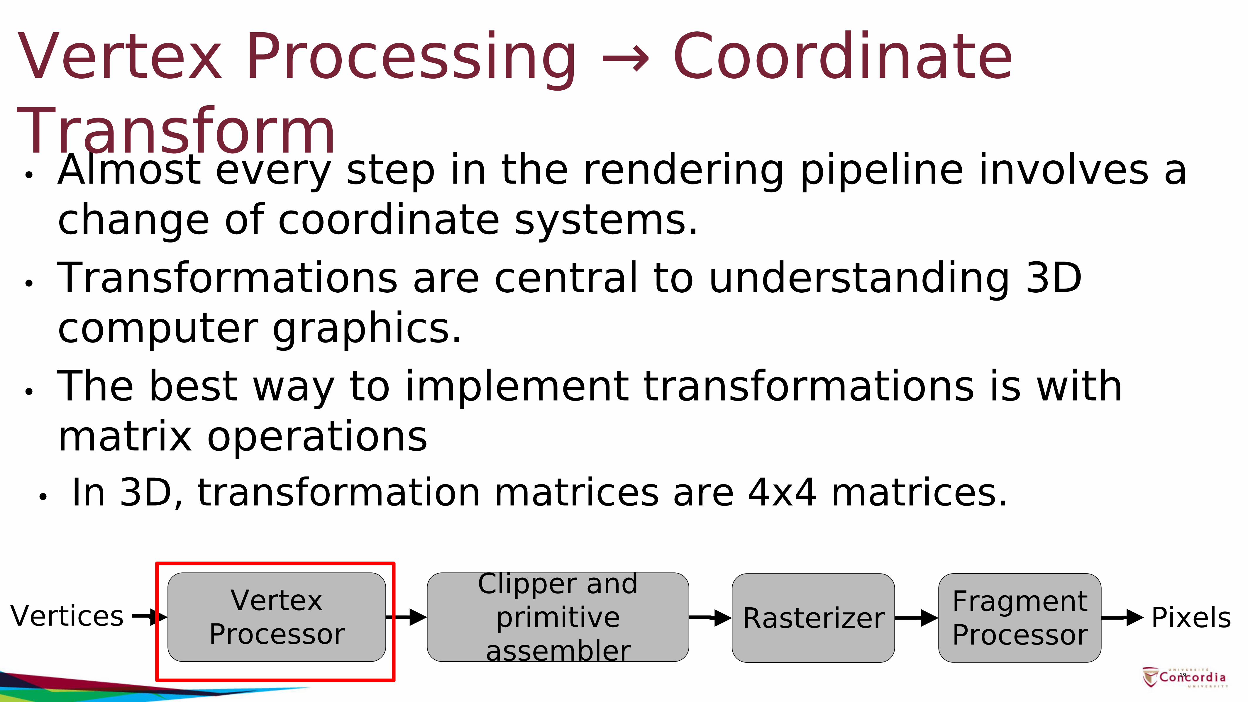
• Almost every step in the rendering pipeline involves a change of coordinate systems.
• Transformations are central to understanding 3D computer graphics.
• The best way to implement transformations is with matrix operations
• In 3D, transformation matrices are 4x4 matrices.
Vertex Processing → Coordinate Transform
19
Vertices Vertex Processor
Clipper and primitive
assemblerRasterizer Fragment
Processor Pixels
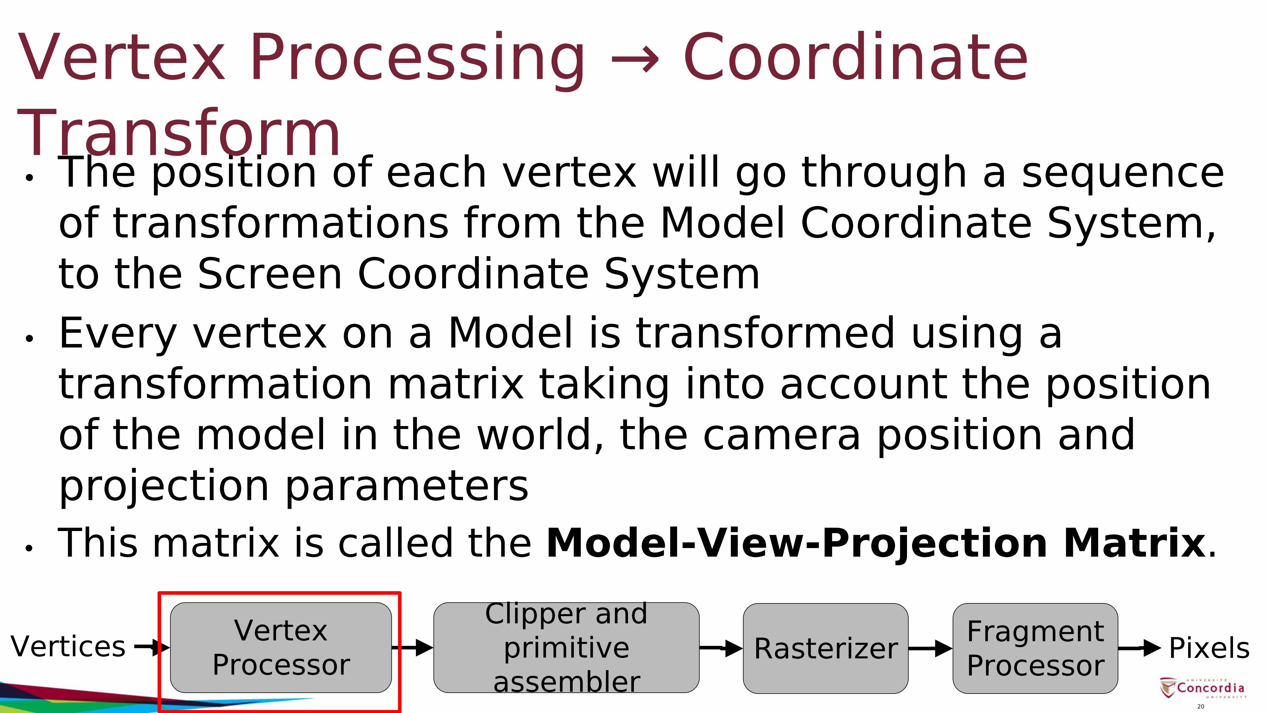
• The position of each vertex will go through a sequence of transformations from the Model Coordinate System, to the Screen Coordinate System
• Every vertex on a Model is transformed using a transformation matrix taking into account the position of the model in the world, the camera position and projection parameters
• This matrix is called the Model-View-Projection Matrix.
Vertex Processing → Coordinate Transform
20
Vertices Vertex Processor
Clipper and primitive
assemblerRasterizer Fragment
Processor Pixels
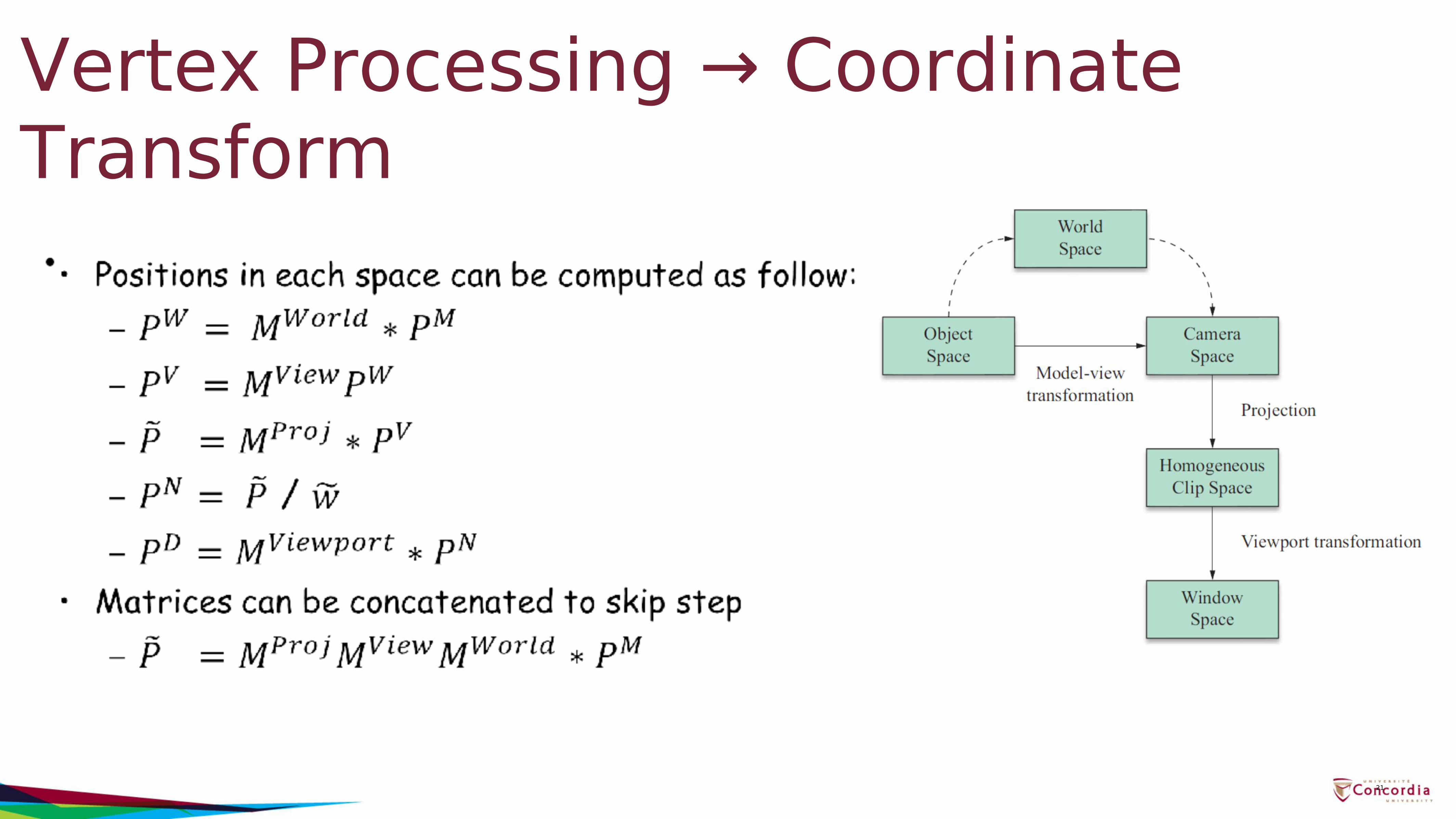
Vertex Processing → Coordinate Transform
21
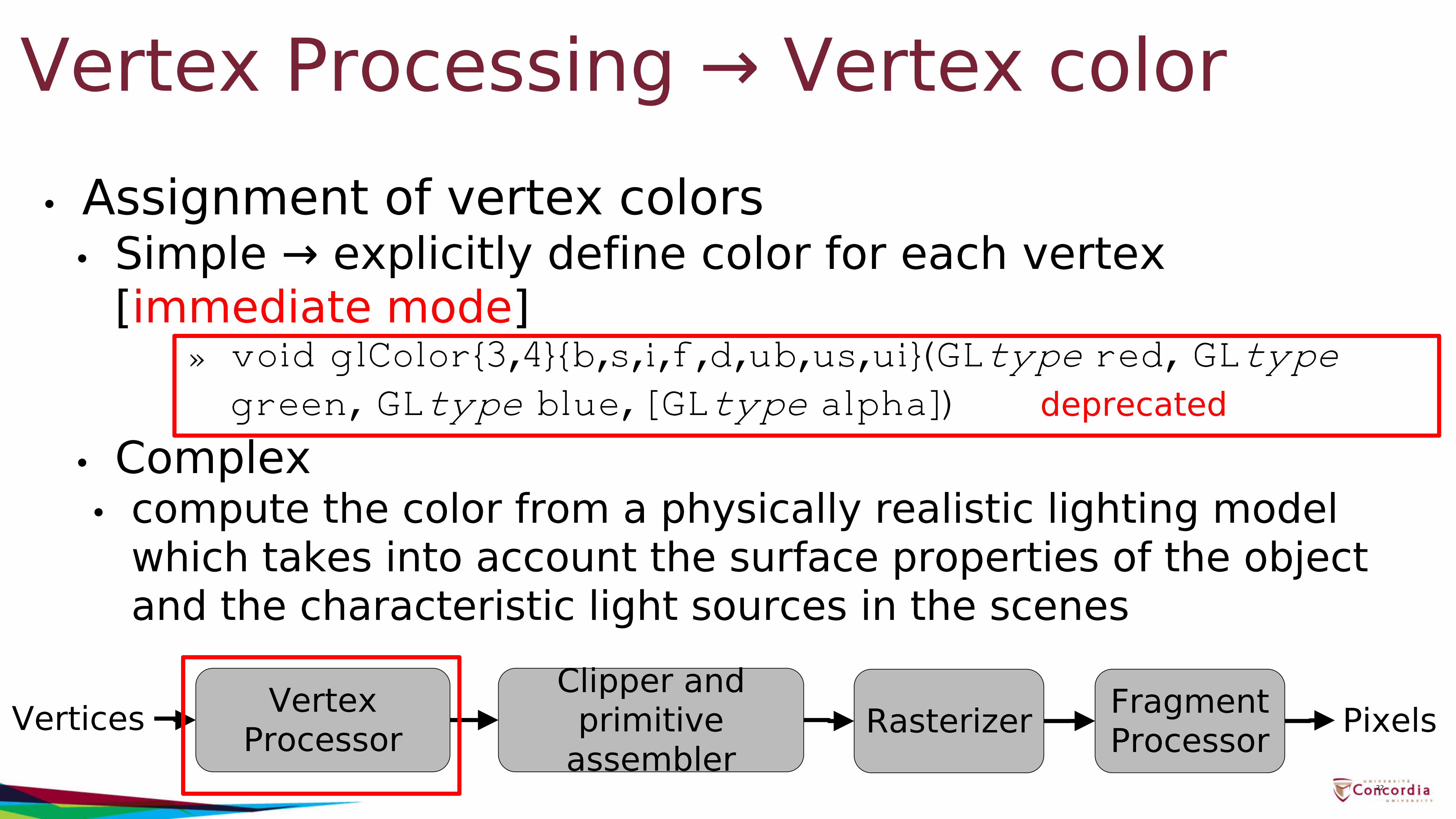
Vertex Processing → Vertex color• Assignment of vertex colors
• Simple → explicitly define color for each vertex [immediate mode]
» void glColor{3,4}{b,s,i,f,d,ub,us,ui}(GLtype red, GLtype green, GLtype blue, [GLtype alpha])
• Complex• compute the color from a physically realistic lighting model
which takes into account the surface properties of the object and the characteristic light sources in the scenes
22
Vertices Vertex Processor
Clipper and primitive
assemblerRasterizer Fragment
Processor Pixels
deprecated
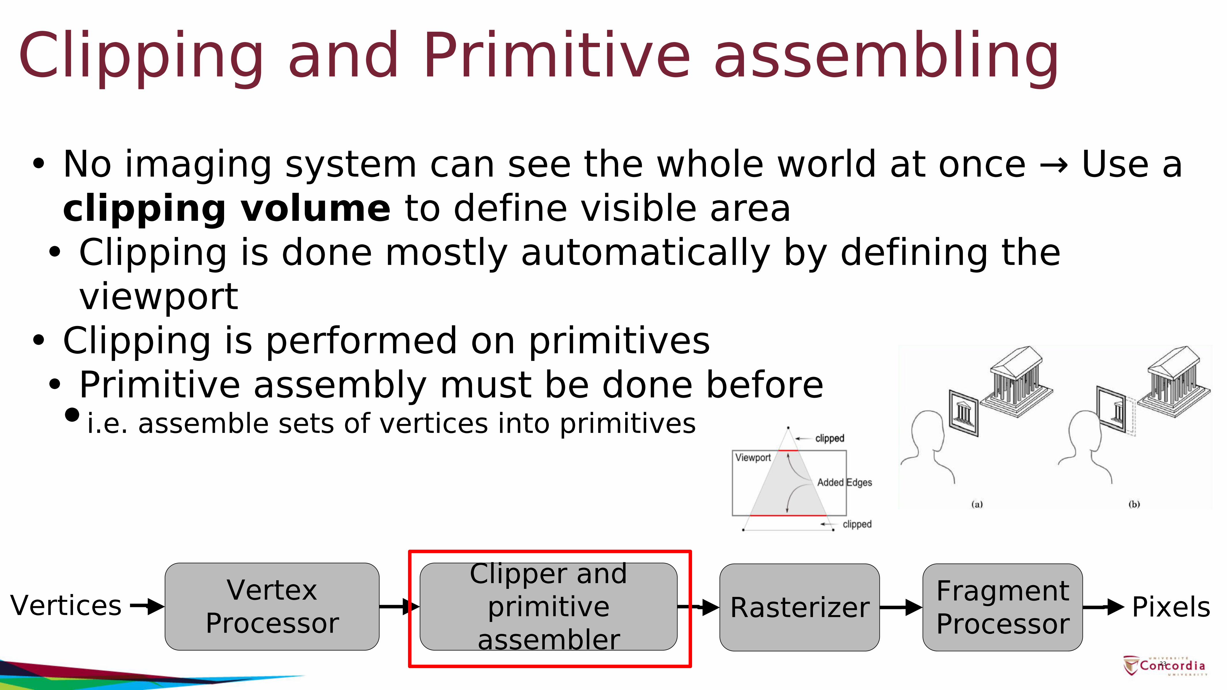
Clipping and Primitive assembling• No imaging system can see the whole world at once → Use a
clipping volume to define visible area• Clipping is done mostly automatically by defining the
viewport• Clipping is performed on primitives• Primitive assembly must be done before•i.e. assemble sets of vertices into primitives
23
Vertices Vertex Processor
Clipper and primitive
assemblerRasterizer Fragment
Processor Pixels
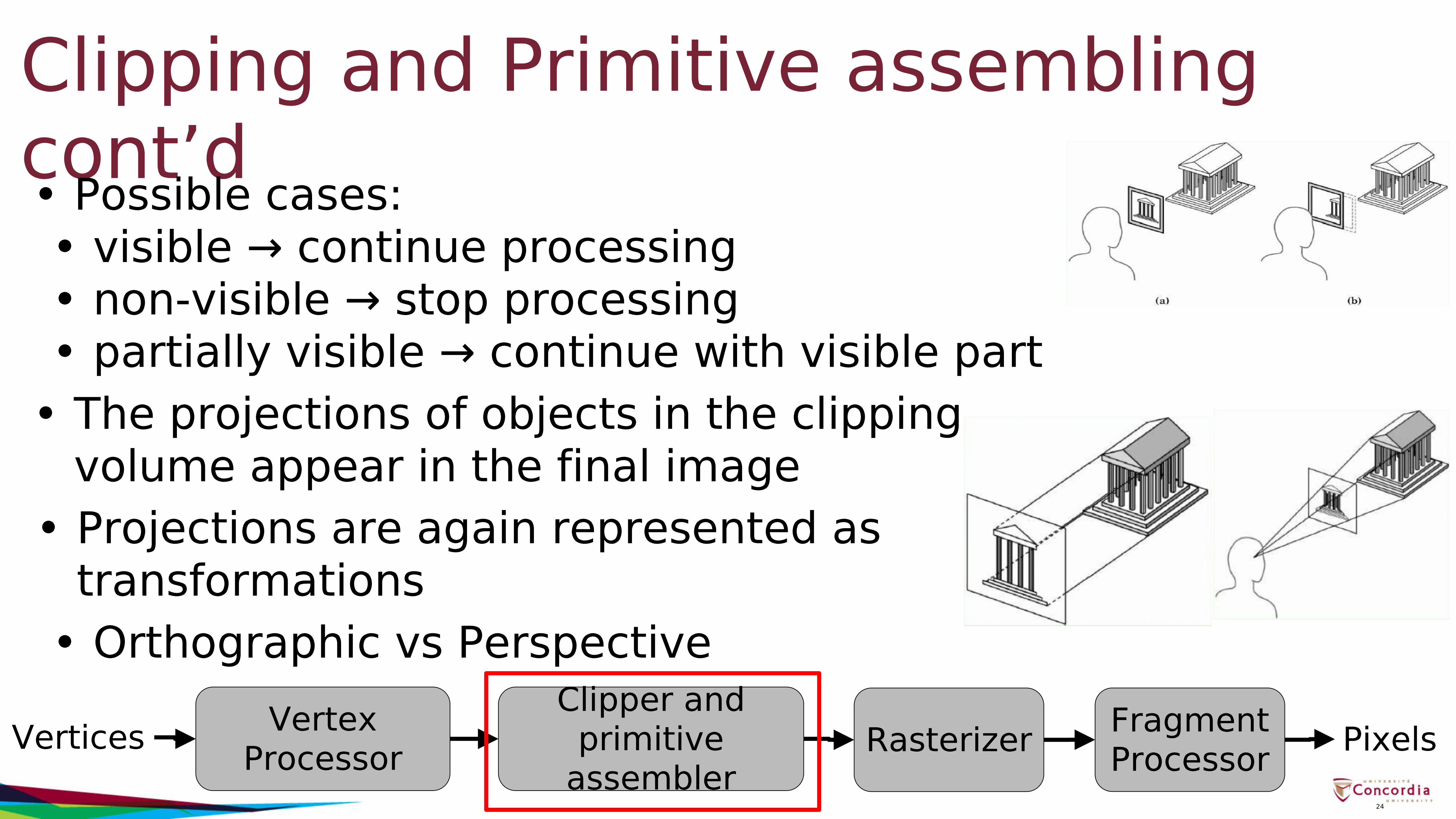
Clipping and Primitive assembling cont’d• Possible cases:
• visible → continue processing• non-visible → stop processing• partially visible → continue with visible part
• The projections of objects in the clipping volume appear in the final image
• Projections are again represented astransformations
• Orthographic vs Perspective
24
Vertices Vertex Processor
Clipper and primitive
assemblerRasterizer Fragment
Processor Pixels
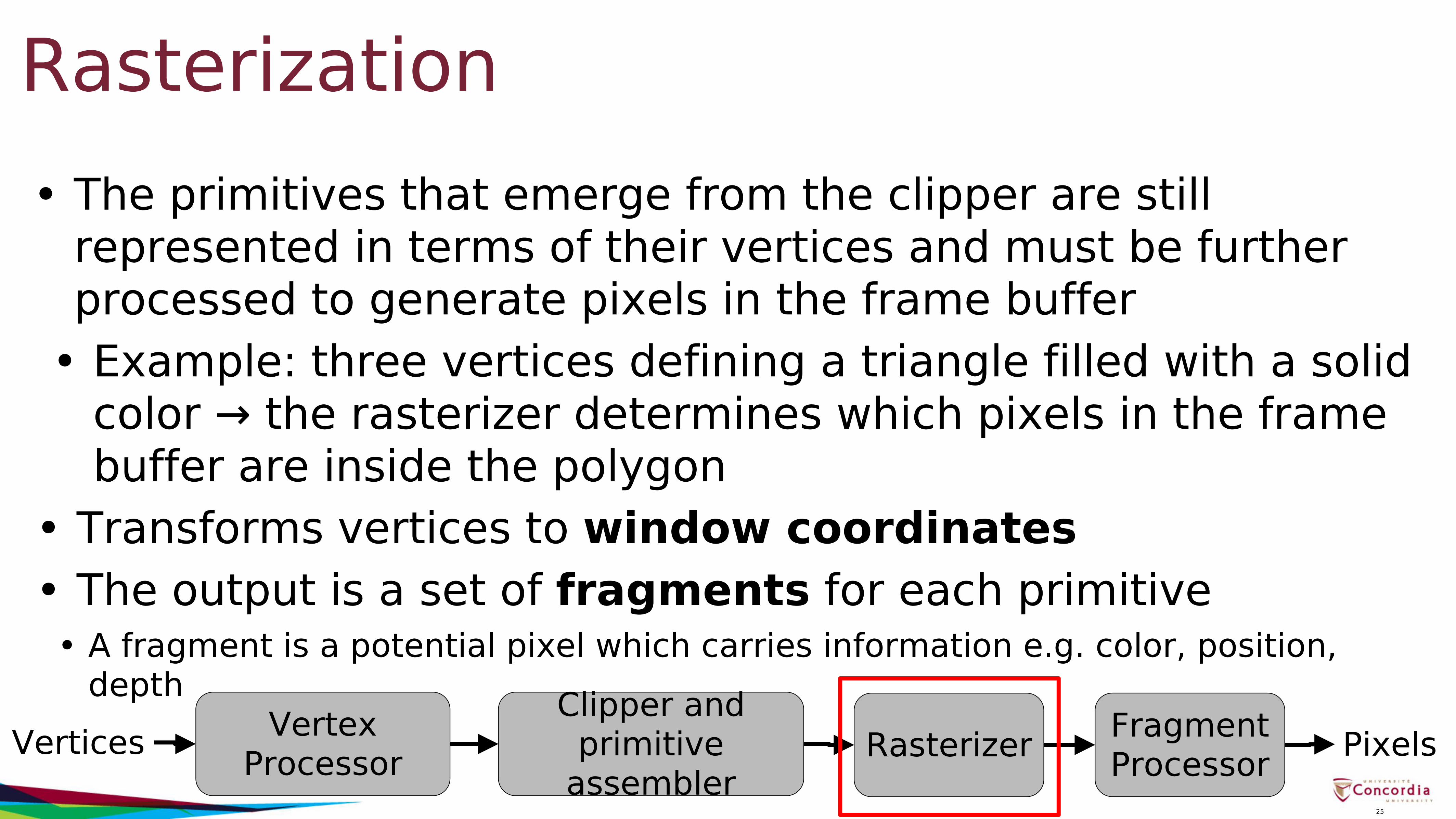
Rasterization• The primitives that emerge from the clipper are still
represented in terms of their vertices and must be further processed to generate pixels in the frame buffer
• Example: three vertices defining a triangle filled with a solid color → the rasterizer determines which pixels in the frame buffer are inside the polygon
• Transforms vertices to window coordinates• The output is a set of fragments for each primitive
• A fragment is a potential pixel which carries information e.g. color, position, depth
25
Vertices Vertex Processor
Clipper and primitive
assemblerRasterizer Fragment
Processor Pixels
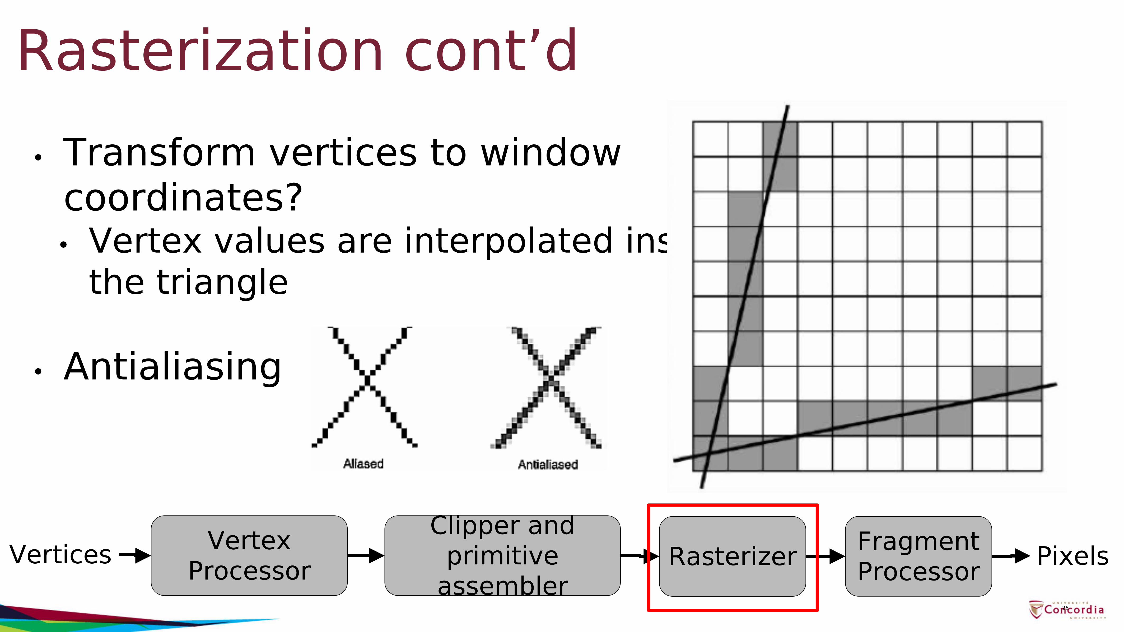
Rasterization cont’d• Transform vertices to window
coordinates?• Vertex values are interpolated inside
the triangle
• Antialiasing
26
Vertices Vertex Processor
Clipper and primitive
assemblerRasterizer Fragment
Processor Pixels
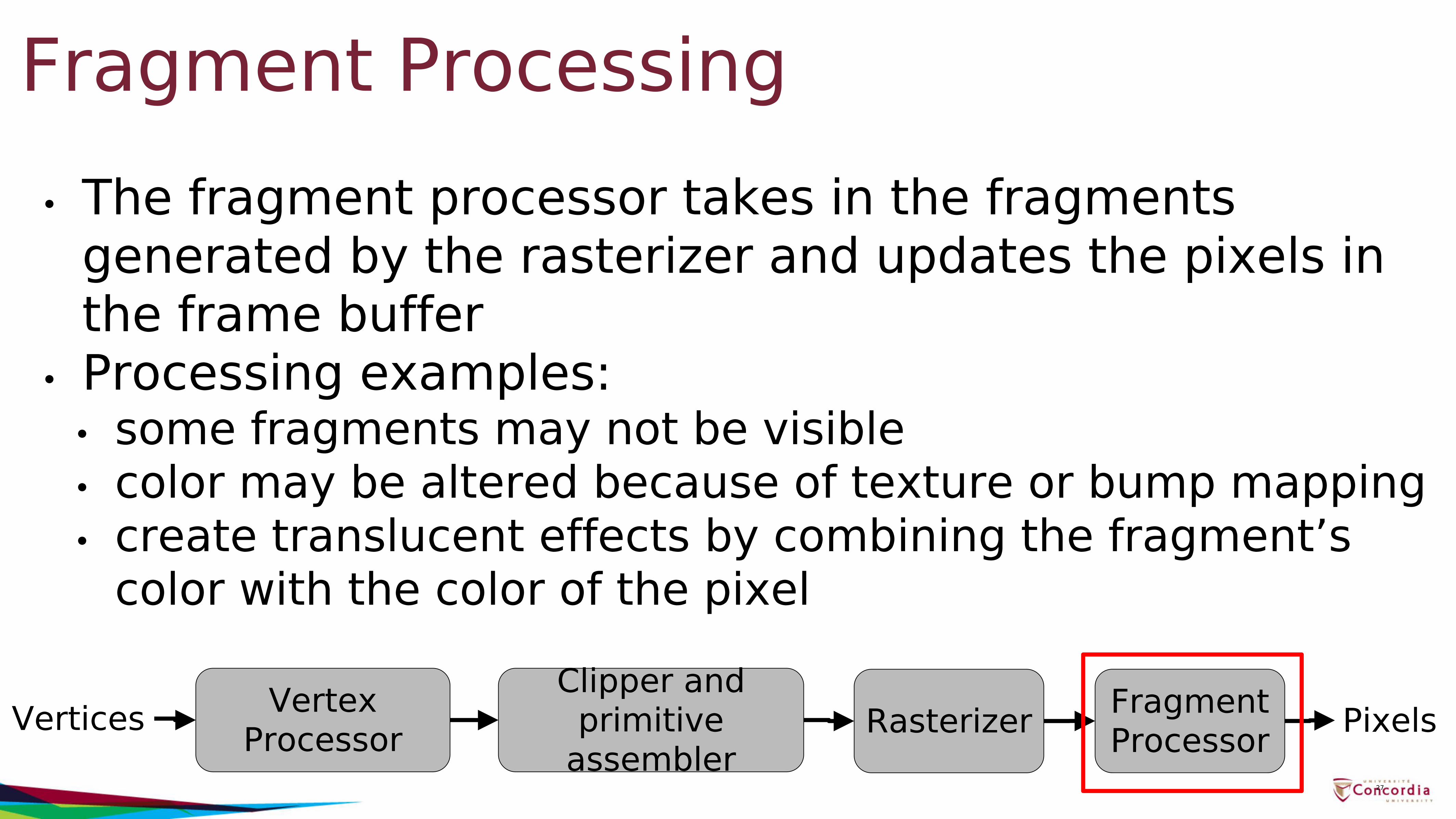
Fragment Processing• The fragment processor takes in the fragments
generated by the rasterizer and updates the pixels in the frame buffer
• Processing examples:• some fragments may not be visible• color may be altered because of texture or bump mapping• create translucent effects by combining the fragment’s
color with the color of the pixel
27
Vertices Vertex Processor
Clipper and primitive
assemblerRasterizer Fragment
Processor Pixels
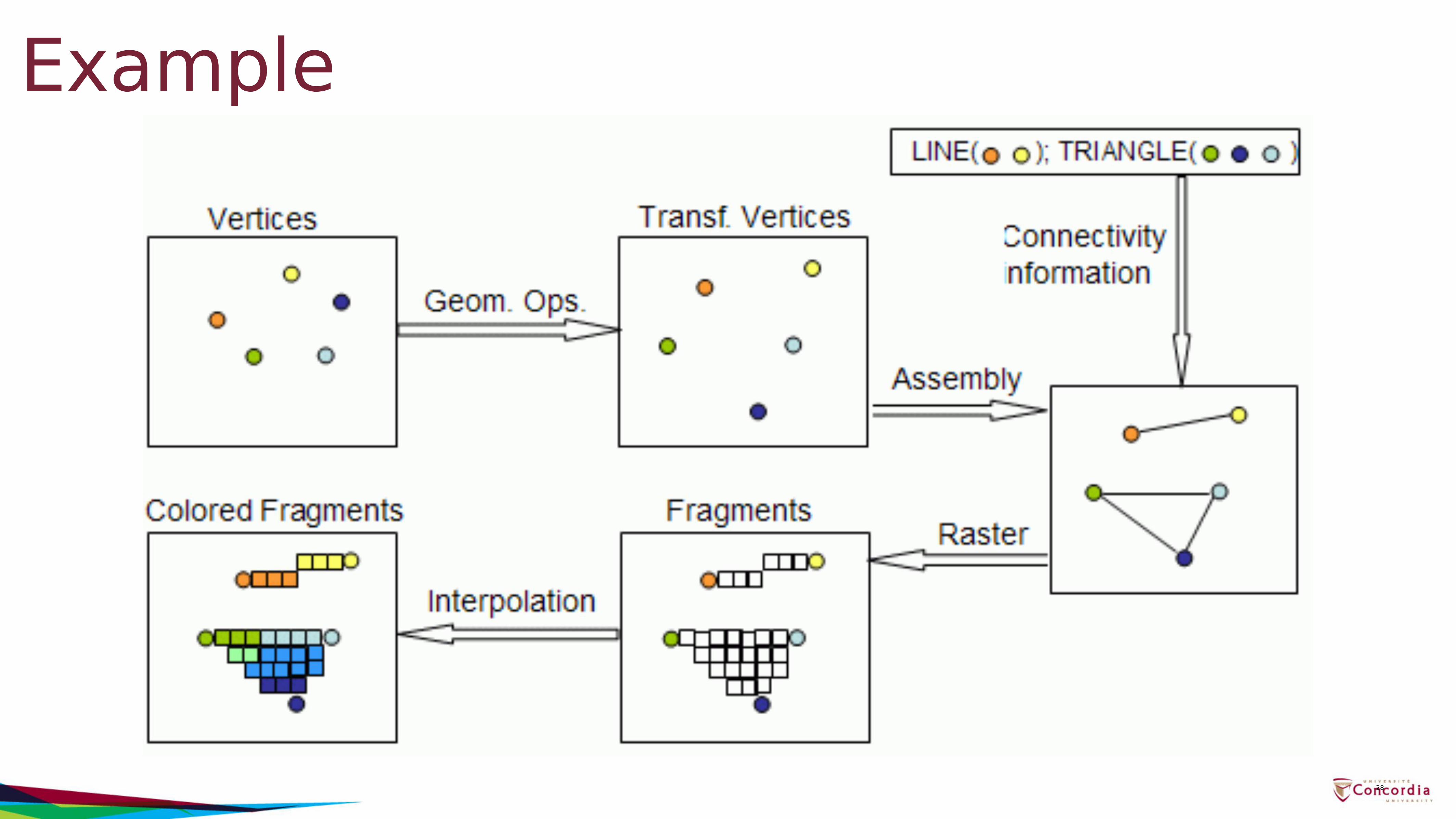
Example
28
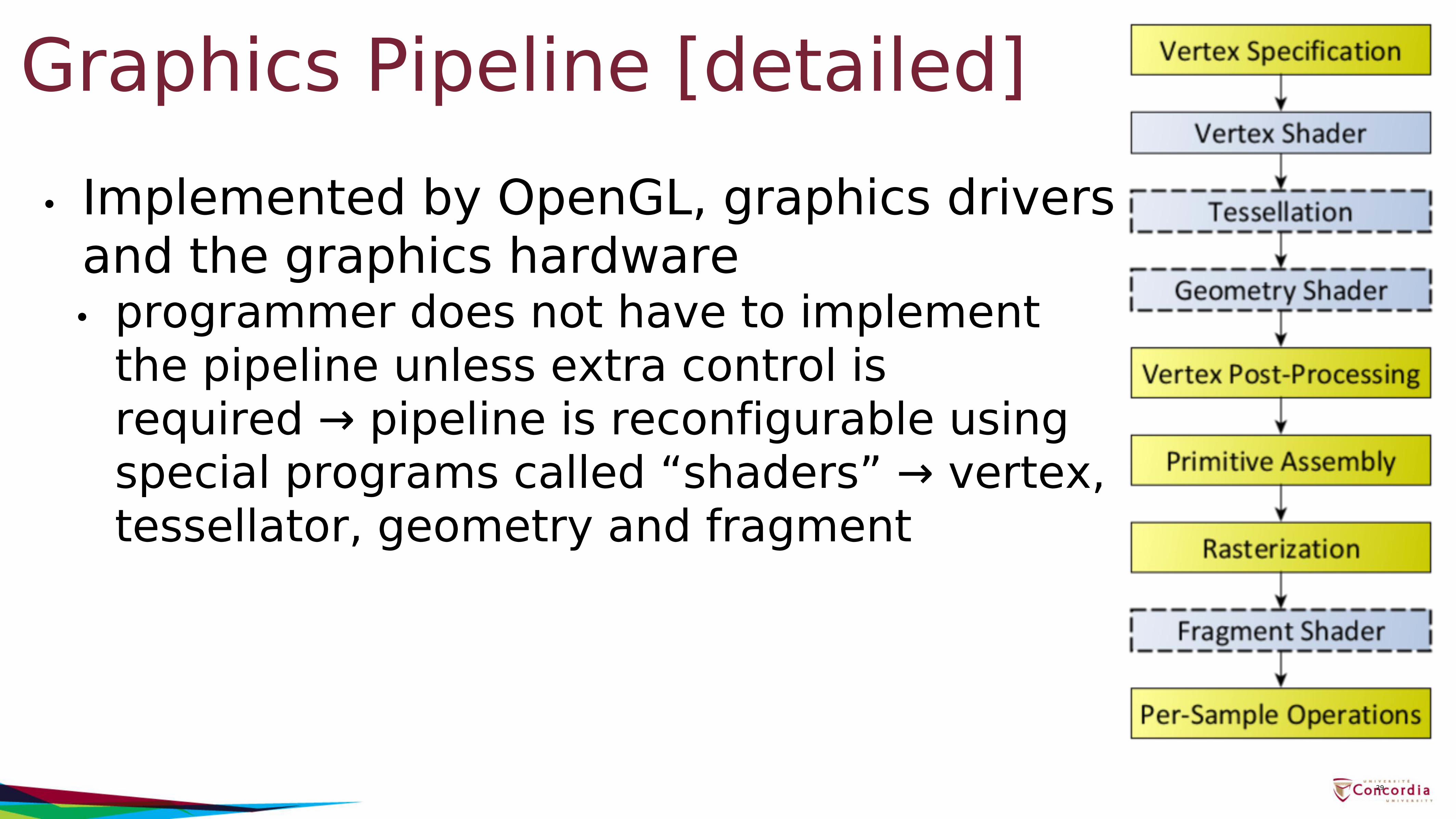
Graphics Pipeline [detailed]• Implemented by OpenGL, graphics drivers
and the graphics hardware• programmer does not have to implement
the pipeline unless extra control is required → pipeline is reconfigurable using special programs called “shaders” → vertex, tessellator, geometry and fragment
29
Primitives & Attributes• In addition to the functions a graphics API needs to
provide a way to represent objects in terms of geometry and appearance• Geometry → Primitives• Appearance → Attributes
30
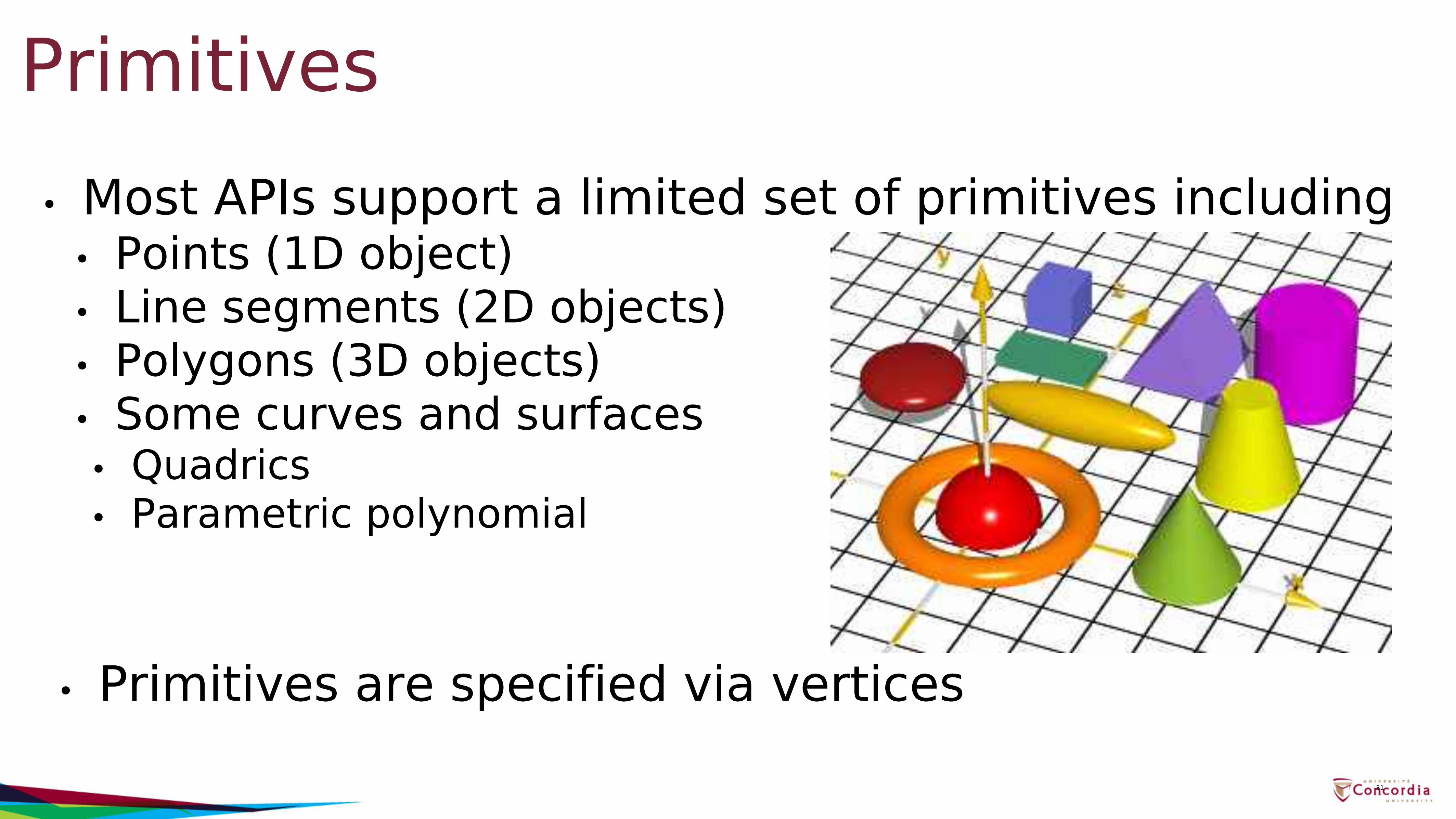
Primitives• Most APIs support a limited set of primitives including
• Points (1D object)• Line segments (2D objects)• Polygons (3D objects)• Some curves and surfaces• Quadrics• Parametric polynomial
• Primitives are specified via vertices31
Polygon Representation• There are different types of Primitives supported by
the Graphics Hardware• Choosing the right primitive type is important to
ensure your geometry renders correctly and efficiently.
32
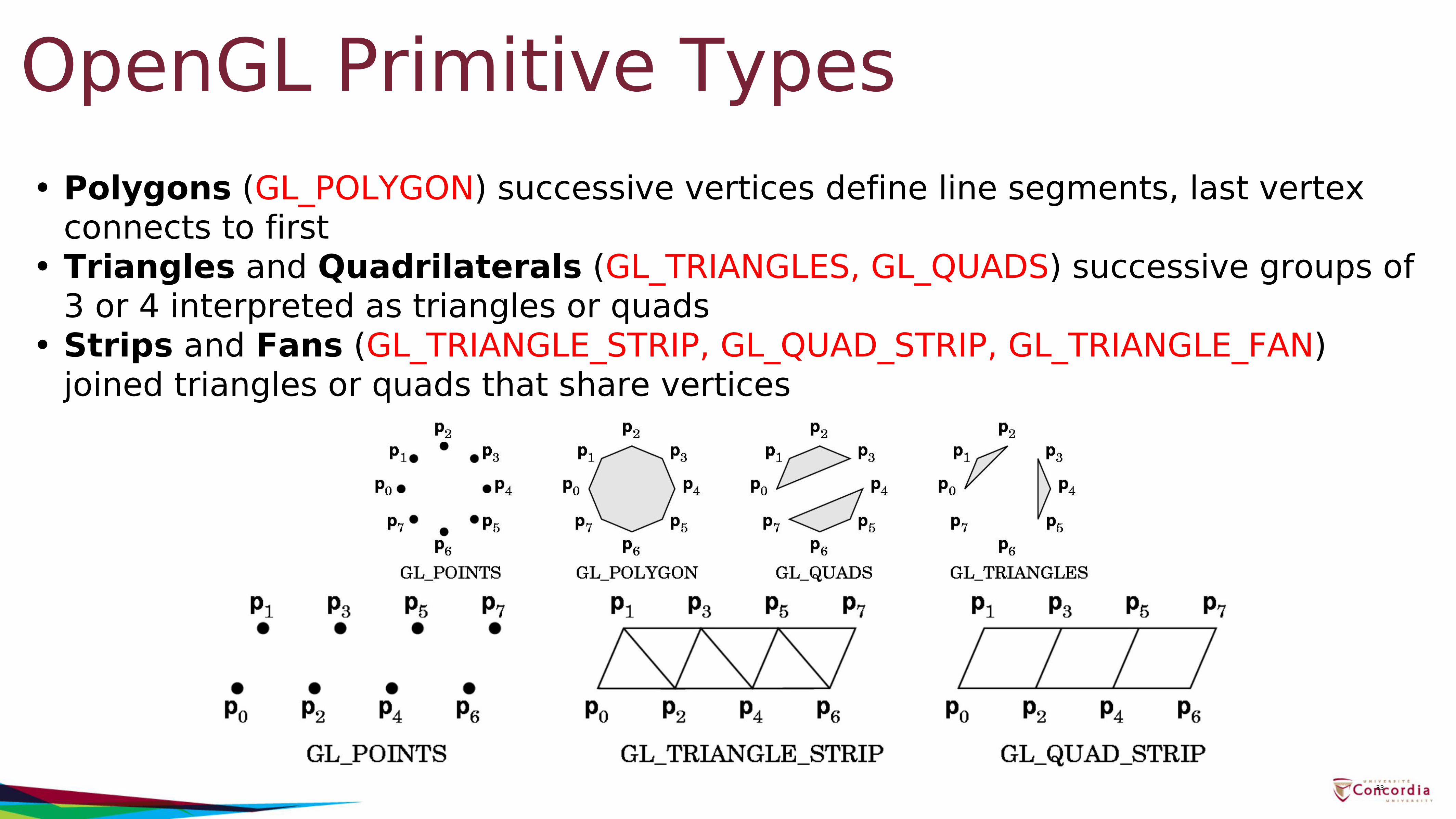
OpenGL Primitive Types• Polygons (GL_POLYGON) successive vertices define line segments, last vertex
connects to first• Triangles and Quadrilaterals (GL_TRIANGLES, GL_QUADS) successive groups of
3 or 4 interpreted as triangles or quads• Strips and Fans (GL_TRIANGLE_STRIP, GL_QUAD_STRIP, GL_TRIANGLE_FAN)
joined triangles or quads that share vertices
33
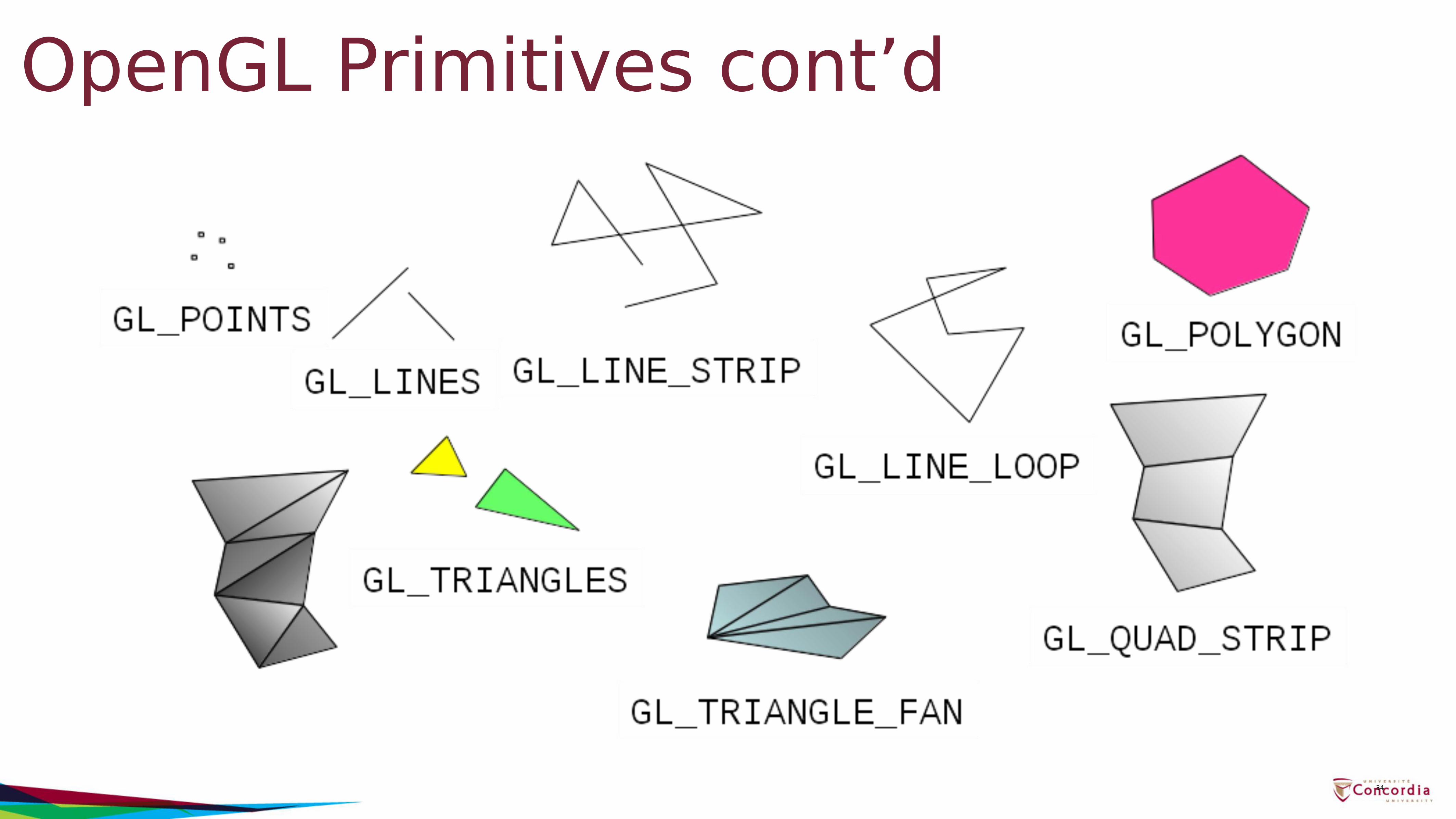
OpenGL Primitives cont’d
34
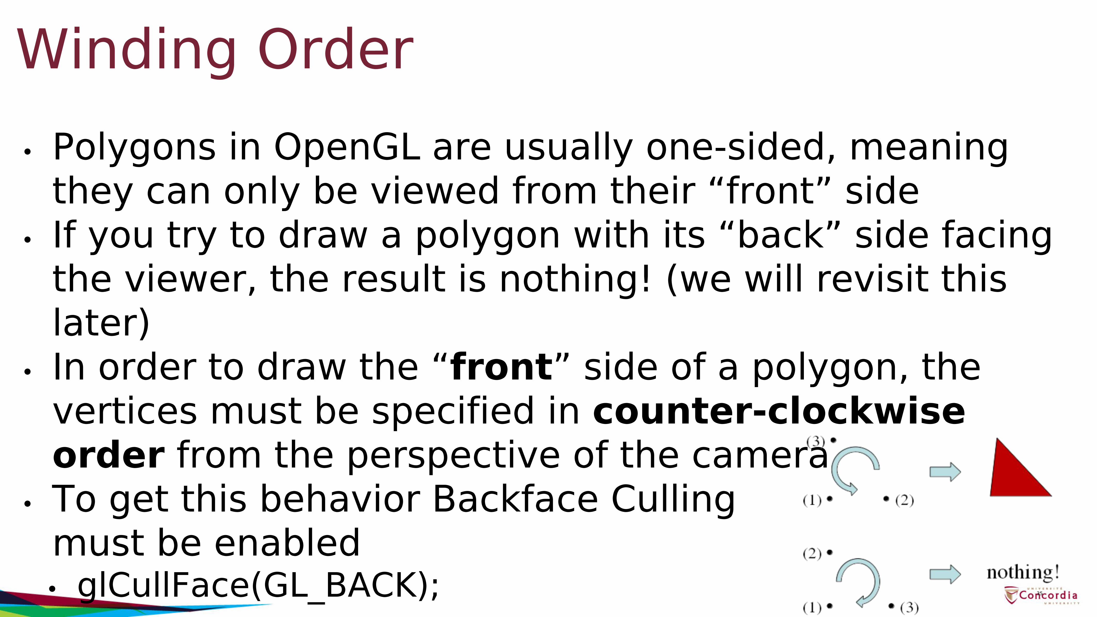
Winding Order• Polygons in OpenGL are usually one-sided, meaning
they can only be viewed from their “front” side• If you try to draw a polygon with its “back” side facing
the viewer, the result is nothing! (we will revisit this later)
• In order to draw the “front” side of a polygon, the vertices must be specified in counter-clockwise order from the perspective of the camera
• To get this behavior Backface Culling must be enabled• glCullFace(GL_BACK); 35
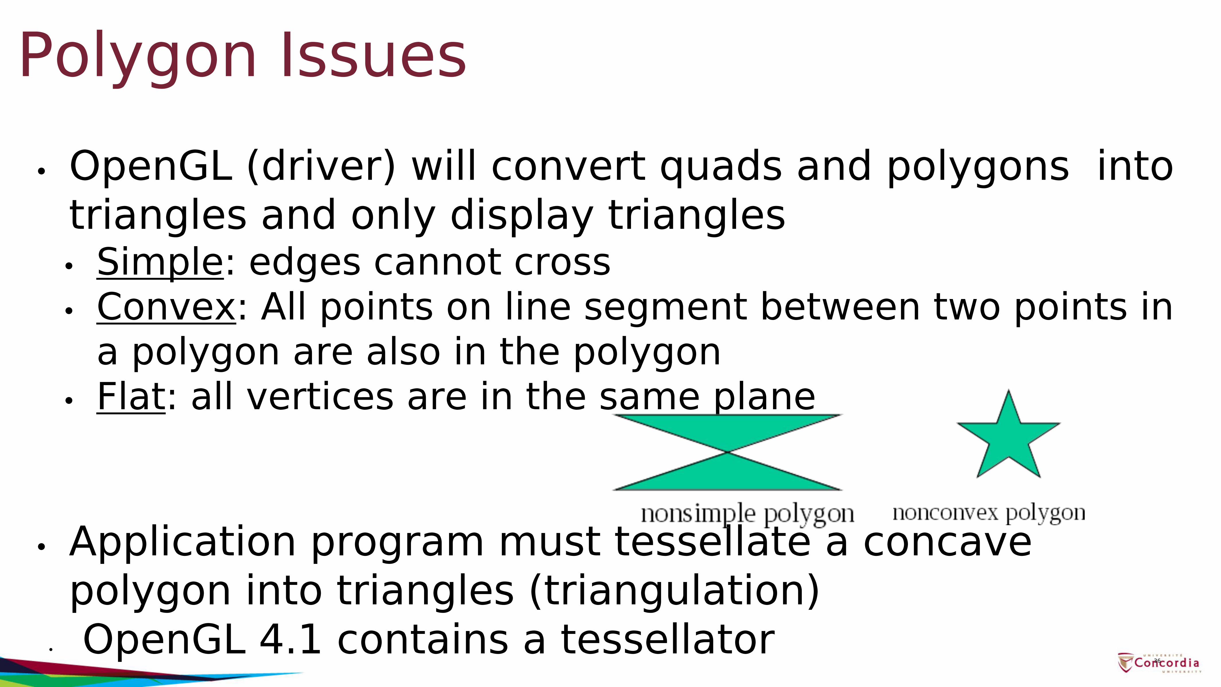
Polygon Issues• OpenGL (driver) will convert quads and polygons into
triangles and only display triangles• Simple: edges cannot cross• Convex: All points on line segment between two points in
a polygon are also in the polygon• Flat: all vertices are in the same plane
• Application program must tessellate a concave polygon into triangles (triangulation)
• OpenGL 4.1 contains a tessellator36
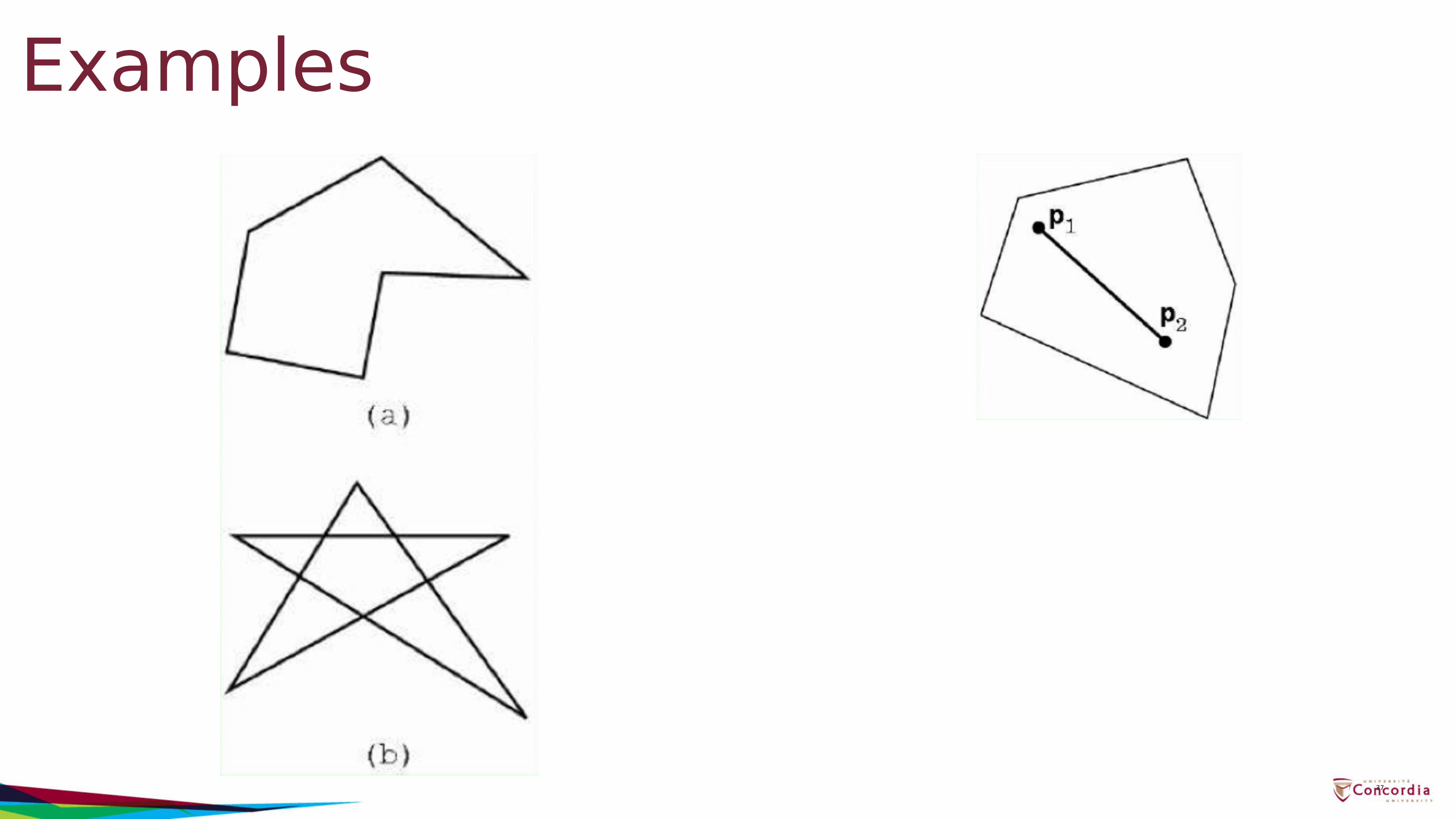
Examples
37
Polygon Issues cont’d• Why only simple and convex?
• Non-convex and non-simple polygons are expensive to process and render
• Convexity and simplicity is expensive to test• Behavior of OpenGL implementation on disallowed
polygons is “undefined”• Some tools in GLU (an older GL Utility functions
library) for decomposing complex polygons (tessellation)
• Triangles are most efficient → use triangles in assignments 38
Attributes• Attributes determine the appearance of objects
• Color (points, lines, polygons)• Size and width (points, lines)• Stipple pattern (lines, polygons)• Polygon mode• Display as filled: solid color or stipple pattern• Display edges• Display vertices
39
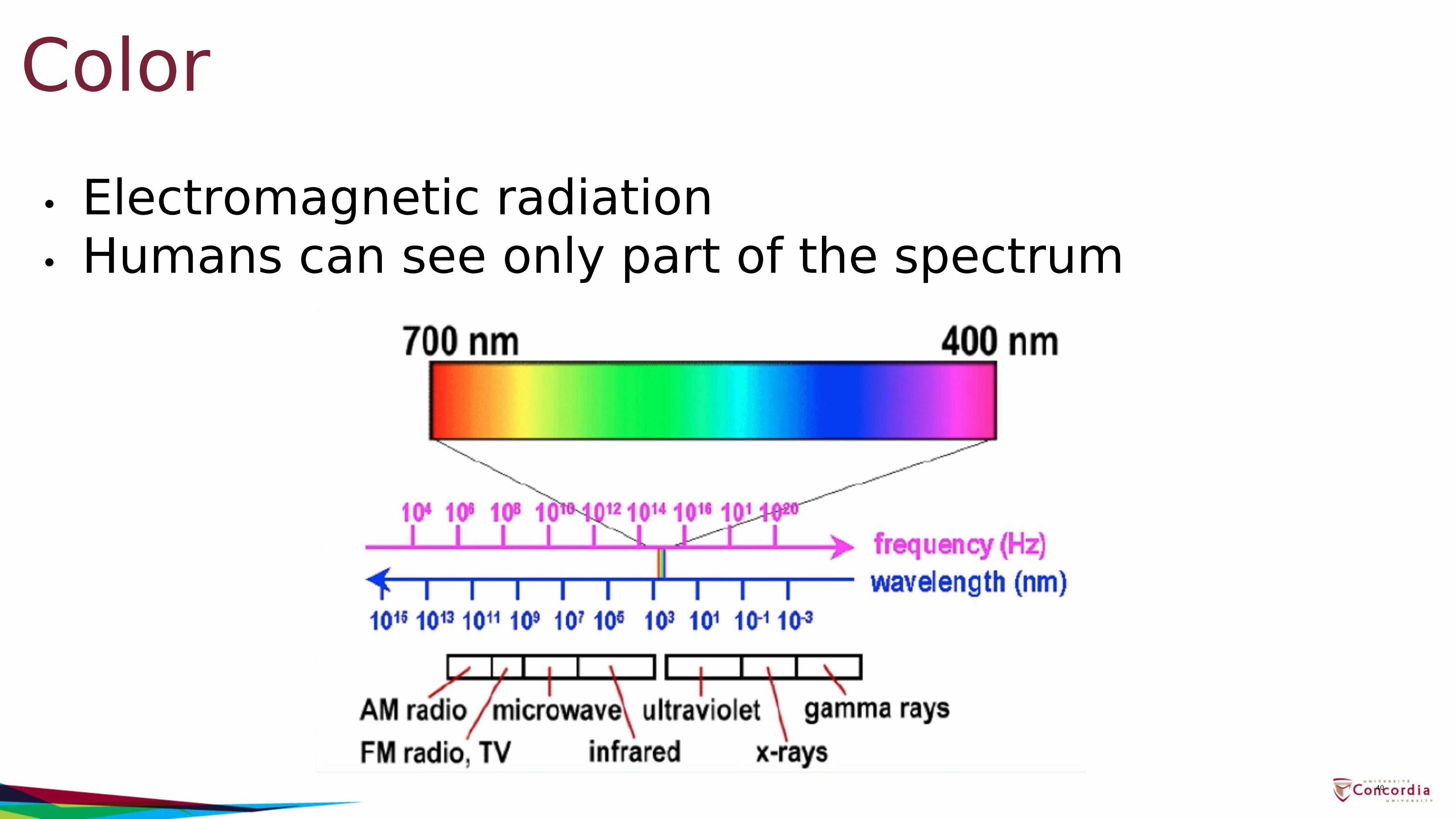
Color• Electromagnetic radiation• Humans can see only part of the spectrum
40
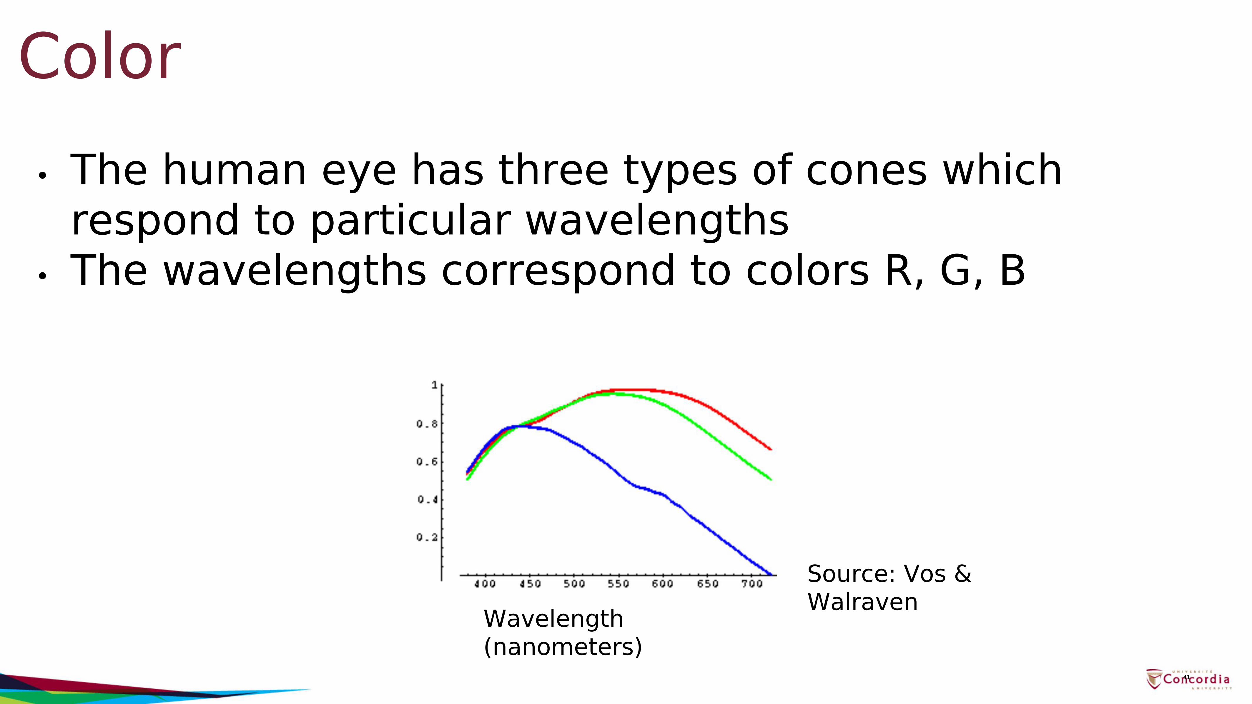
Color• The human eye has three types of cones which
respond to particular wavelengths• The wavelengths correspond to colors R, G, B
41
Source: Vos & WalravenWavelength
(nanometers)
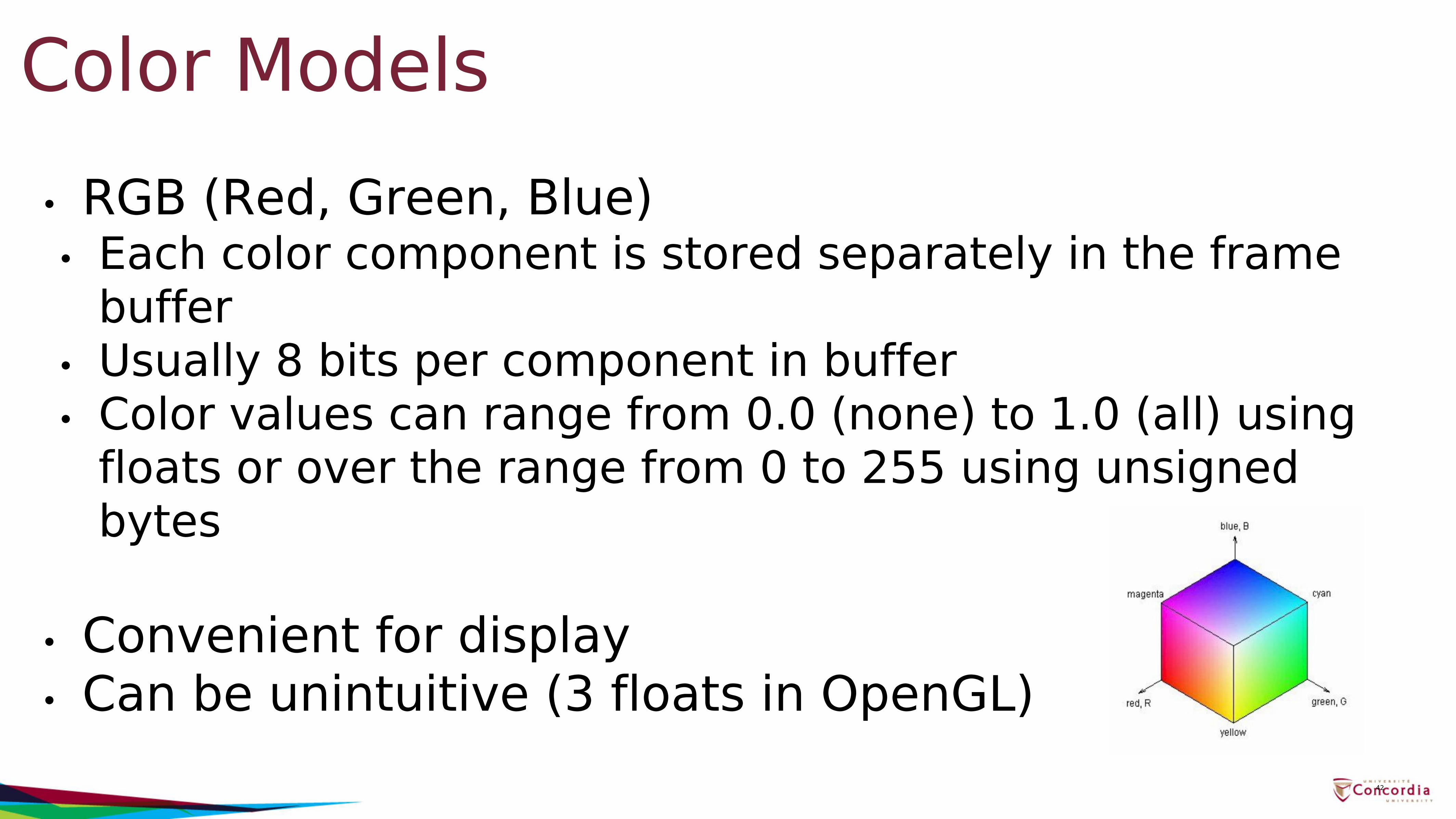
Color Models• RGB (Red, Green, Blue)• Each color component is stored separately in the frame
buffer• Usually 8 bits per component in buffer• Color values can range from 0.0 (none) to 1.0 (all) using
floats or over the range from 0 to 255 using unsigned bytes
• Convenient for display• Can be unintuitive (3 floats in OpenGL)
42
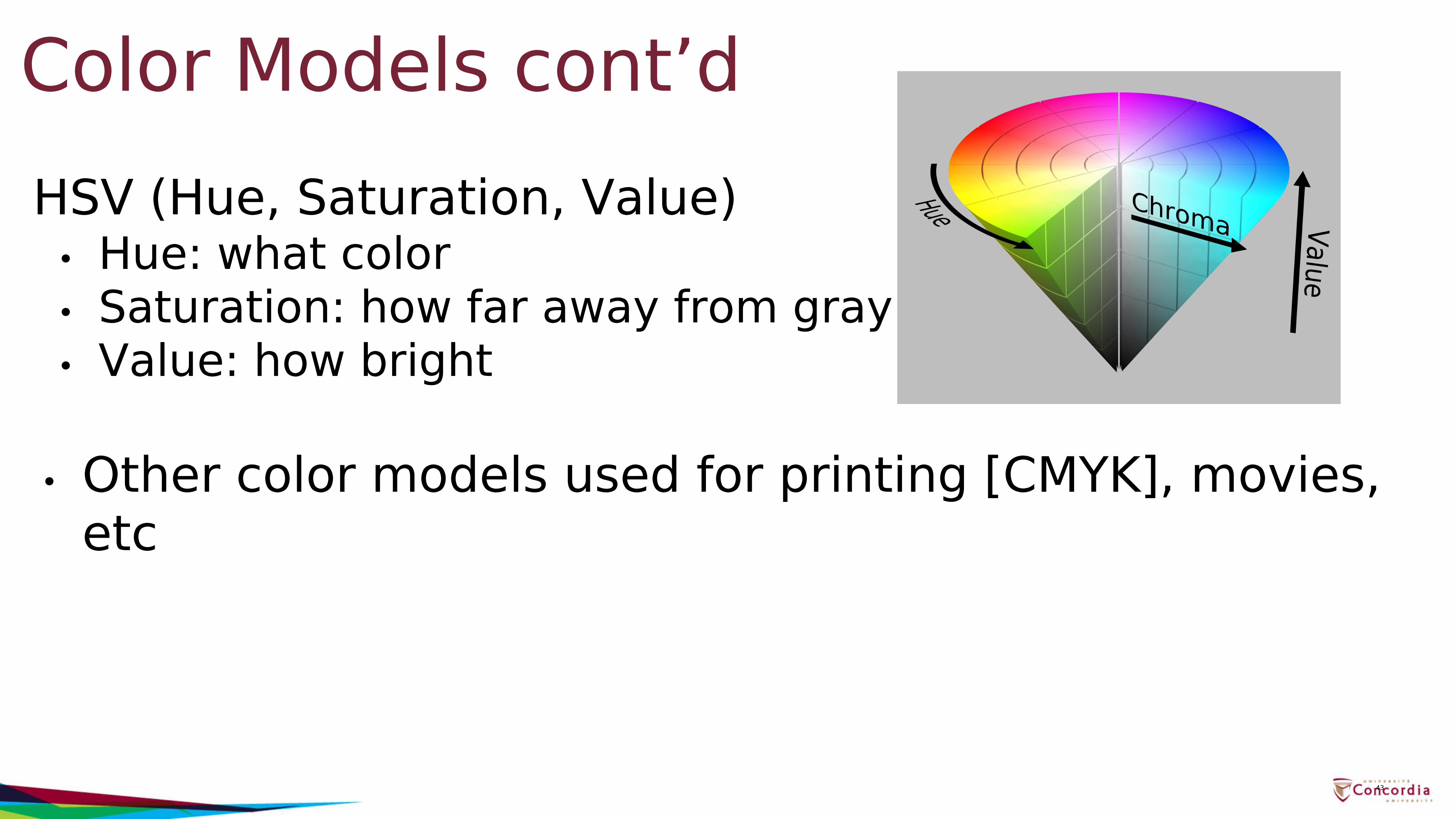
Color Models cont’dHSV (Hue, Saturation, Value)
• Hue: what color• Saturation: how far away from gray• Value: how bright
• Other color models used for printing [CMYK], movies, etc
43
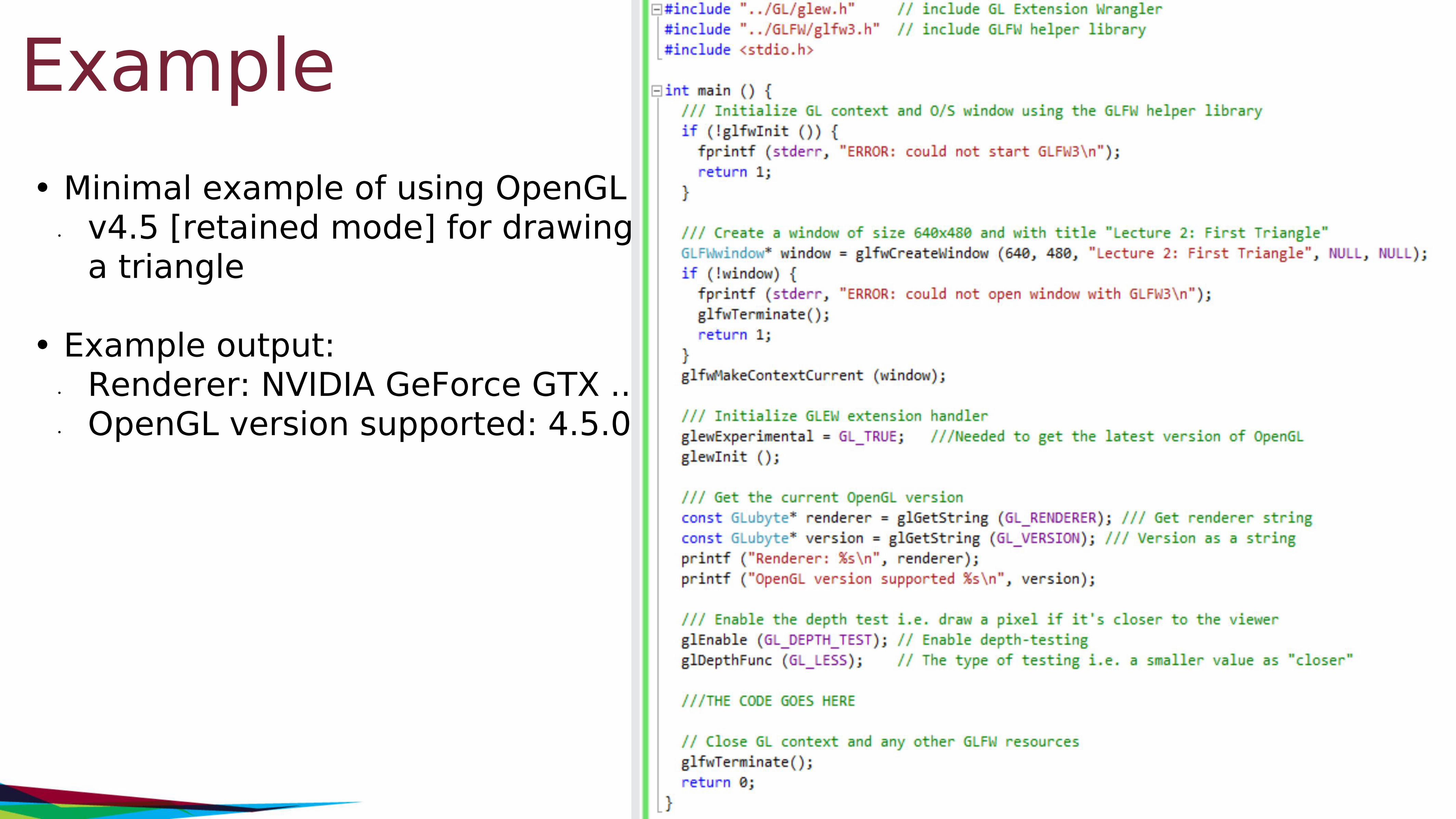
Example• Minimal example of using OpenGL
• v4.5 [retained mode] for drawing a triangle
• Example output:• Renderer: NVIDIA GeForce GTX ...• OpenGL version supported: 4.5.0
44
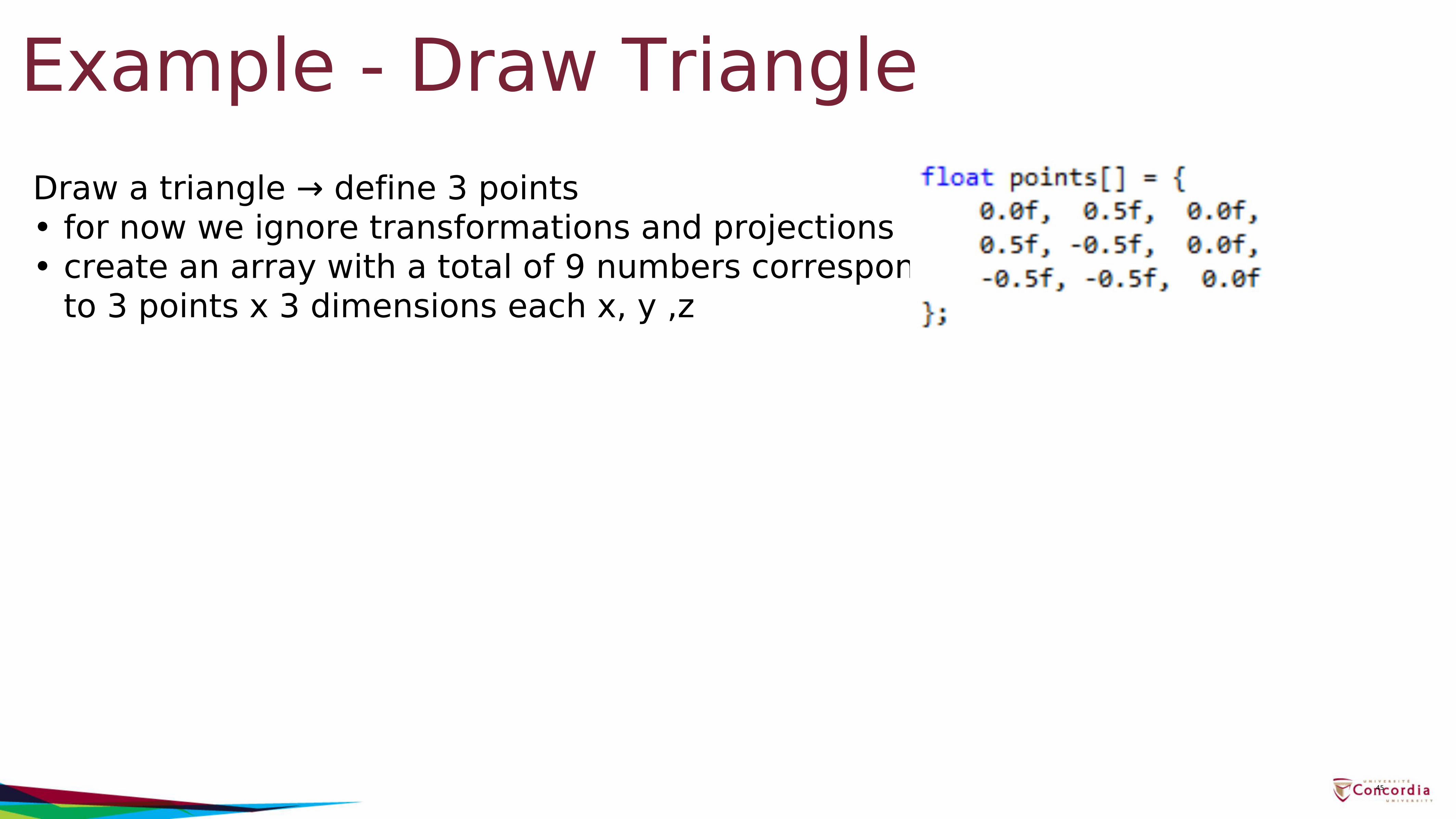
Example - Draw TriangleDraw a triangle → define 3 points• for now we ignore transformations and projections• create an array with a total of 9 numbers corresponding
to 3 points x 3 dimensions each x, y ,z
45
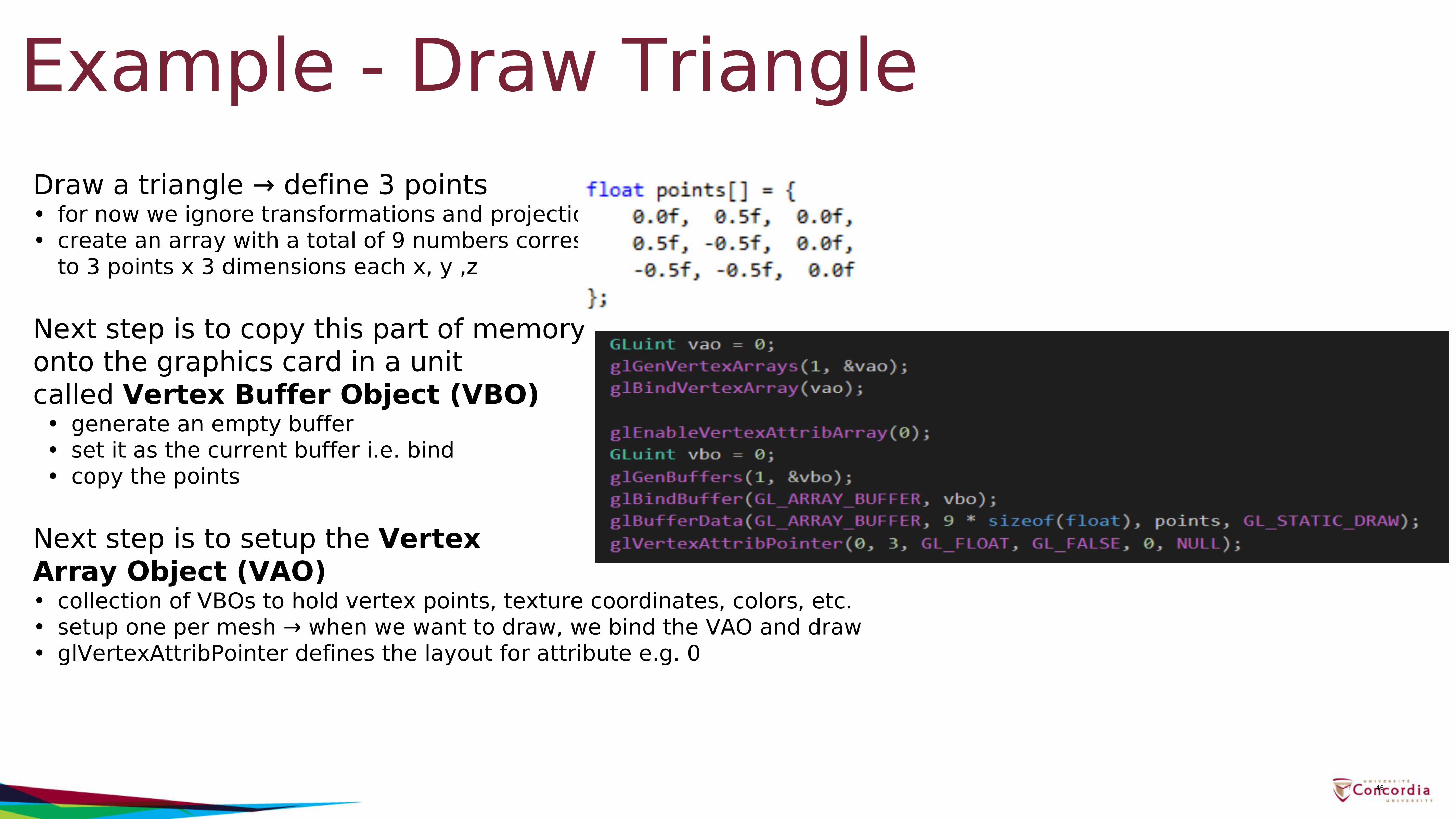
Draw a triangle → define 3 points• for now we ignore transformations and projections• create an array with a total of 9 numbers corresponding
to 3 points x 3 dimensions each x, y ,z
Next step is to copy this part of memory onto the graphics card in a unit called Vertex Buffer Object (VBO)• generate an empty buffer• set it as the current buffer i.e. bind• copy the points
Next step is to setup the Vertex Array Object (VAO)• collection of VBOs to hold vertex points, texture coordinates, colors, etc.• setup one per mesh → when we want to draw, we bind the VAO and draw• glVertexAttribPointer defines the layout for attribute e.g. 0
Example - Draw Triangle
46
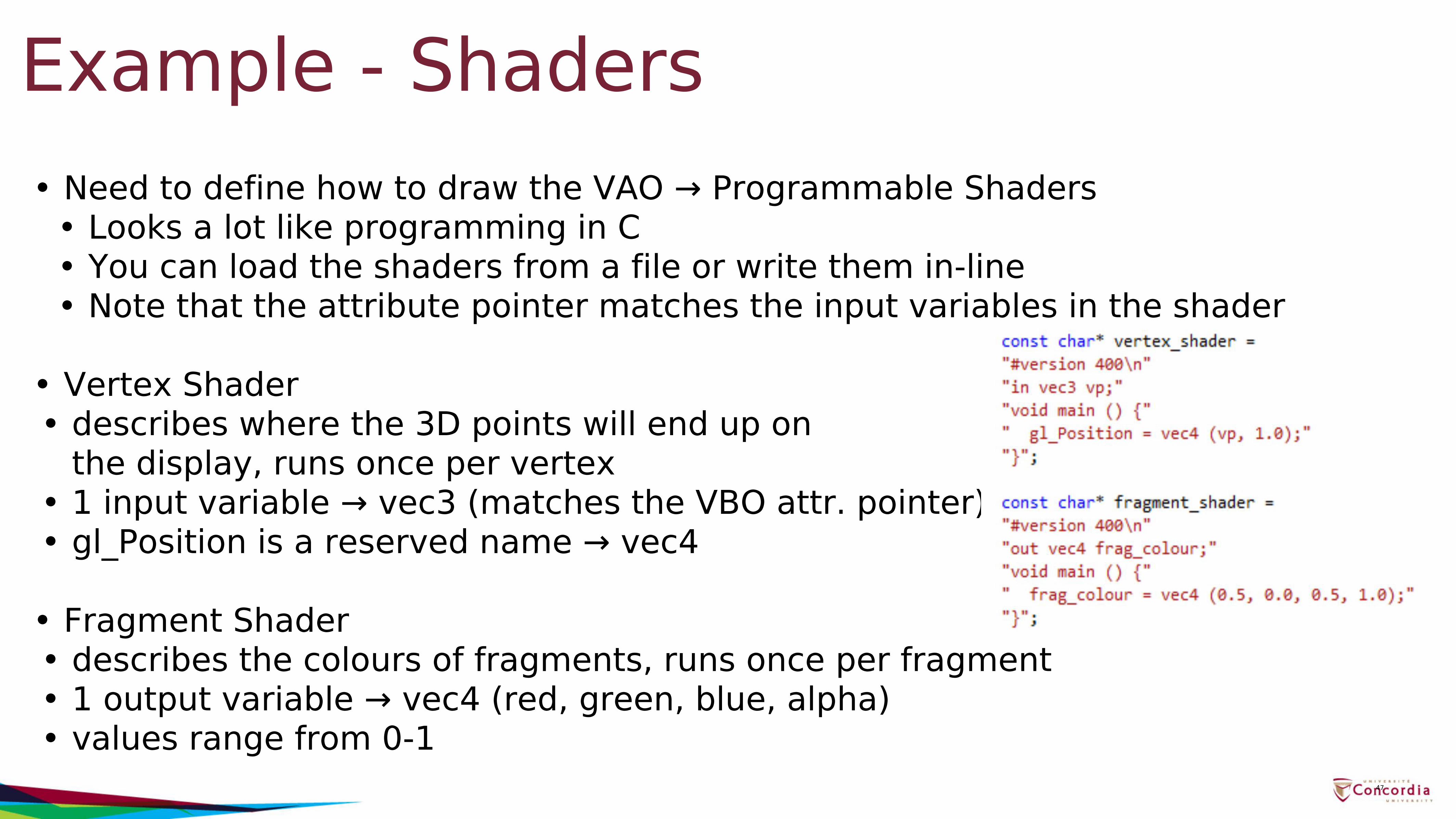
Example - Shaders• Need to define how to draw the VAO → Programmable Shaders
• Looks a lot like programming in C• You can load the shaders from a file or write them in-line• Note that the attribute pointer matches the input variables in the shader
• Vertex Shader• describes where the 3D points will end up on
the display, runs once per vertex• 1 input variable → vec3 (matches the VBO attr. pointer)• gl_Position is a reserved name → vec4
• Fragment Shader• describes the colours of fragments, runs once per fragment• 1 output variable → vec4 (red, green, blue, alpha)• values range from 0-1
47
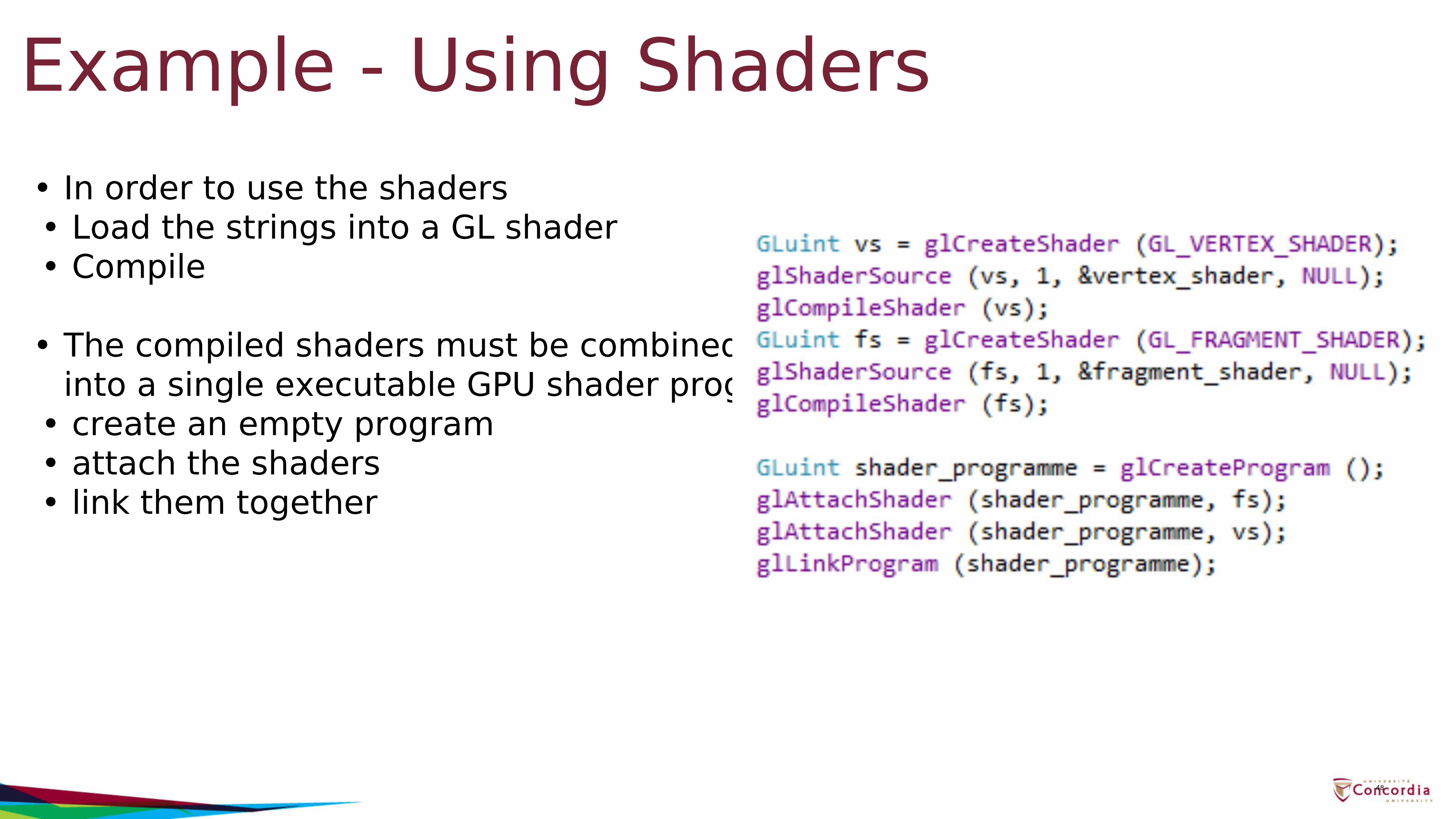
Example - Using Shaders• In order to use the shaders• Load the strings into a GL shader• Compile
• The compiled shaders must be combined into a single executable GPU shader program
• create an empty program• attach the shaders• link them together
48
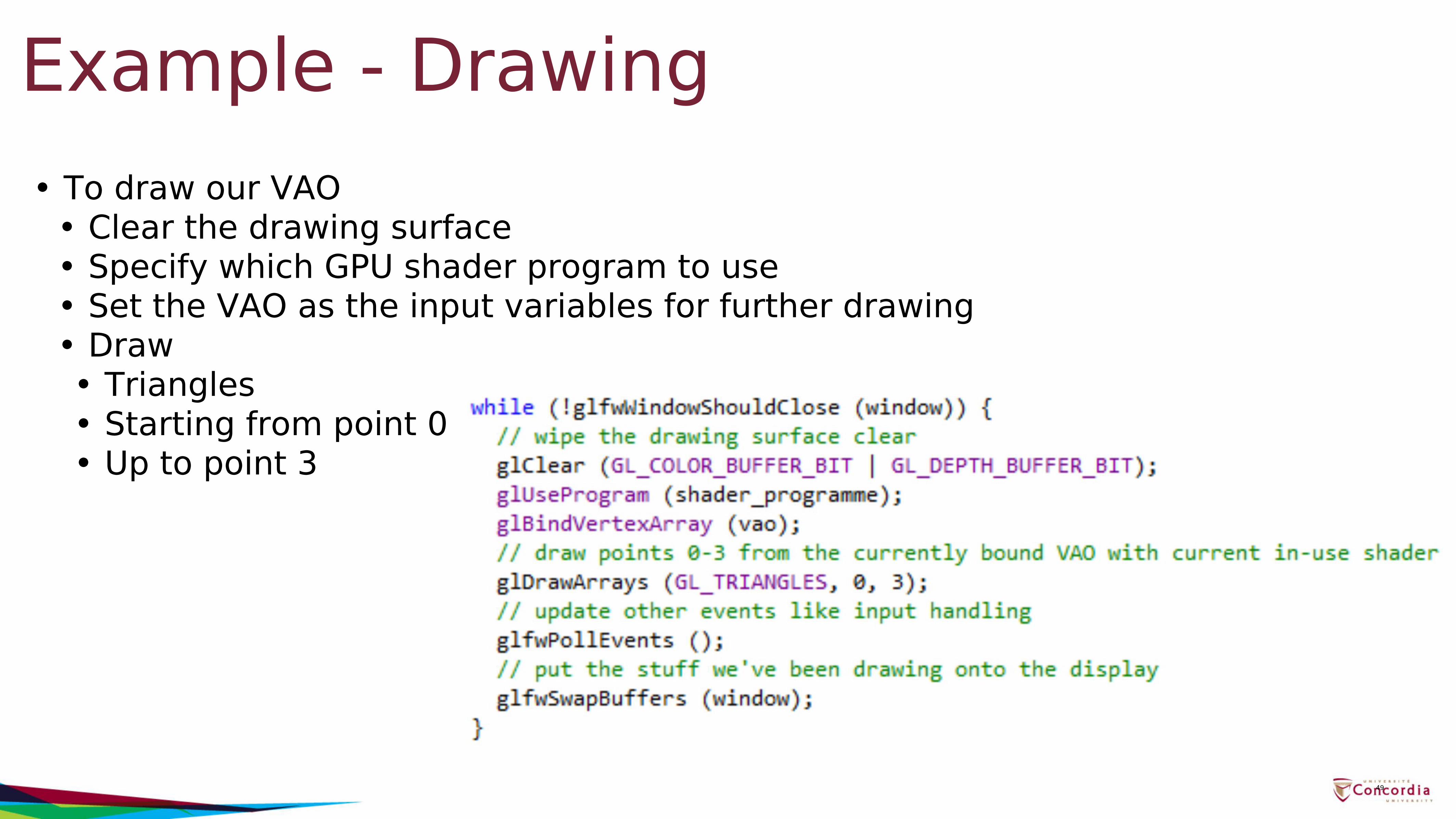
Example - Drawing• To draw our VAO
• Clear the drawing surface• Specify which GPU shader program to use• Set the VAO as the input variables for further drawing• Draw• Triangles• Starting from point 0• Up to point 3
49
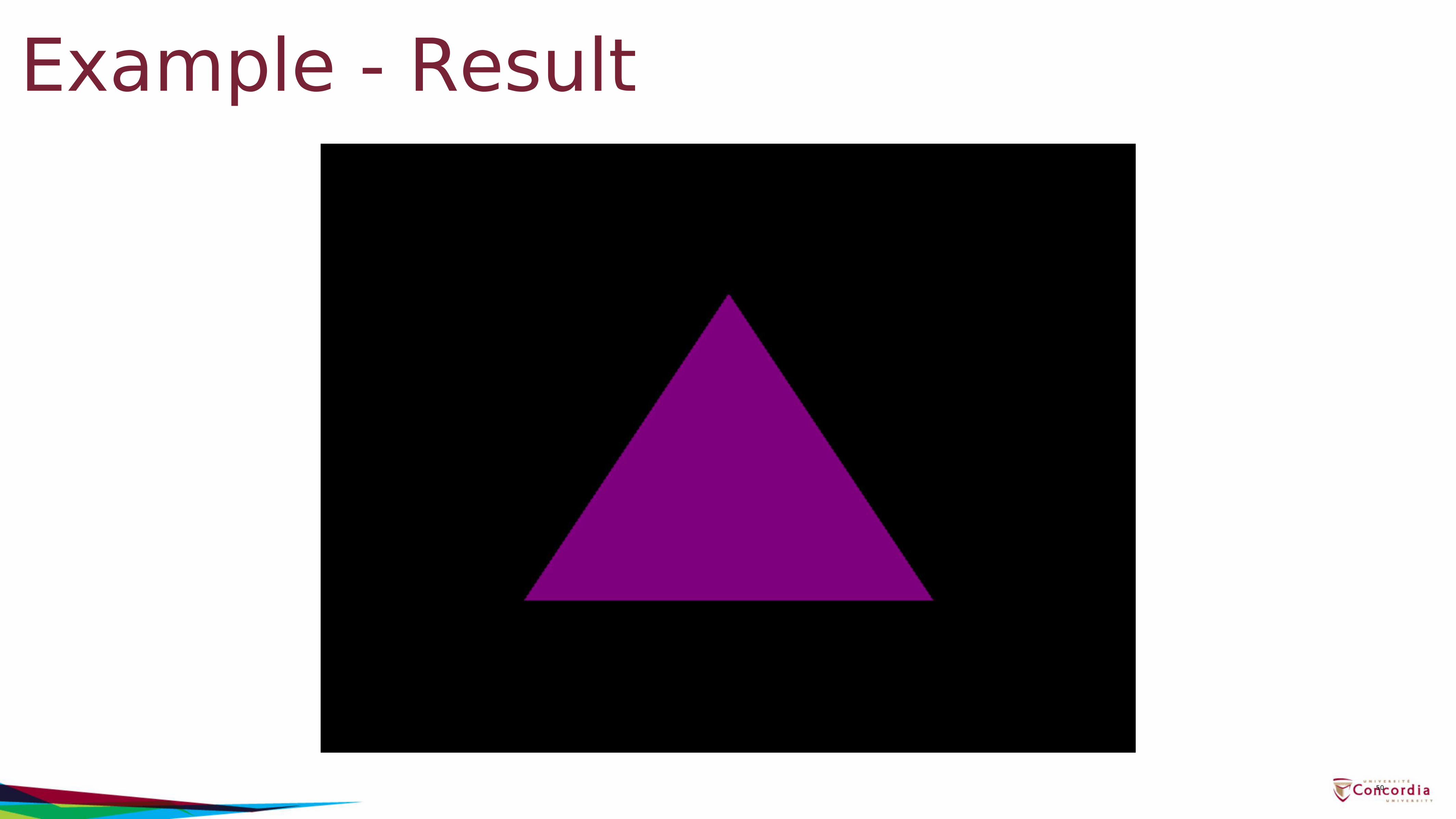
Example - Result
50
Review• OpenGL API• Graphics Pipeline• Primitives: vertices, lines, polygons• Attributes: color• Example
51
Next Lecture▪ Input and Interaction
▪ Client/Server Model▪ Callbacks▪ Double Buffering▪ Hidden Surface Removal▪ Simple Transformations
52

53
Recommended