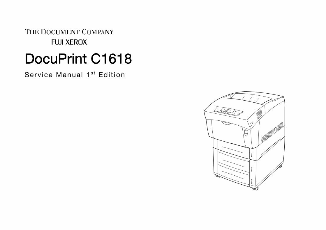
DocuPrint C161DocuPrint C161DocuPrint C161DocuPrint C1618888Serv ice Manua l 1s t Edi t ion
DocuPrint C1618DocuPrint C1618DocuPrint C1618DocuPrint C1618Service Manual 1st Edition
Issued: April 2002
This service manual covers the following models:
Electro-photographic laser Color Printer manufacturedby FUJI XEROX Co., Ltd
hhhh DocuPrint C1618
Related:
hhhh No other related manuals are issued other than
this service manual.
Confidentiality:
hhhh This service manual is issued intending use by
maintenance service personnel authorized byXEROX. Copying, transferring or leasing thismanual without prior consent by XEROX isprohibited.
hhhh Whenever a page is eliminated because of
issuance of a replacement page containing
changes or modifications, burn it or take the
necessary action including cutting by a shredder.
hhhh Be careful of handling to avoid missing or
damaging the manual.
Revision and Modification Information:
When design changes or revisions relating to thisservice manual occur, the overseas technicalinformation or overseas service bulletin may beissued as supplementary information until such
changes will be accommodated in the updatedversion of this service manual.
Important changes including
revisions of spare part numbers
and adjustment specifications
must immediately be reflected on
the respective pages of this
service manual upon reception of
such information.
Edited by: Fuji Xerox Co., Ltd. CSSC TD&LC SDEC
213-8508, Sakado 3-2-1 Takatsu-ku Kawasaki-shi Kanagawa-kenKSP/R&D Business Park Bldg 6A7
TEL: 044-812-7637
[XEROX], [The Document Company] are registered trademarks
PRINTED IN JAPAN
CompanyName
Department
Tel No:
Name EmployeeNo.
( )Material No.SM-NL300004-0-01-0
CAUTION
PrefaceScope of this DocumentHow to Use this ManualTerms and Symbols
Abbreviations
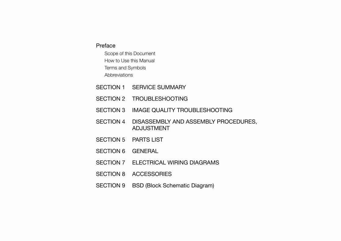
SECTION 1 SERVICE SUMMARY
SECTION 2 TROUBLESHOOTING
SECTION 3 IMAGE QUALITY TROUBLESHOOTING
SECTION 4 DISASSEMBLY AND ASSEMBLY PROCEDURES,ADJUSTMENT
SECTION 5 PARTS LIST
SECTION 6 GENERAL
SECTION 7 ELECTRICAL WIRING DIAGRAMS
SECTION 8 ACCESSORIES
SECTION 9 BSD (Block Schematic Diagram)

Preface
ContentsPreface0-1
Contents
1. Scope of this Document.......................................................................................... 2
2. How to Use this Manual .......................................................................................... 2
2.1 Organization of this Manual ................................................................................ 2
2.2 Revision Information........................................................................................... 2
3. Terms and Symbols ................................................................................................ 3
4. Abbreviations .......................................................................................................... 4
Preface2. How to Use this Manual
0-2
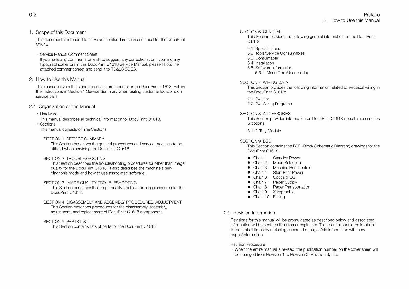
1. Scope of this DocumentThis document is intended to serve as the standard service manual for the DocuPrintC1618.
・ Service Manual Comment SheetIf you have any comments or wish to suggest any corrections, or if you find anytypographical errors in this DocuPrint C1618 Service Manual, please fill out theattached comment sheet and send it to TD&LC SDEC.
2. How to Use this ManualThis manual covers the standard service procedures for the DocuPrint C1618. Followthe instructions in Section 1 Service Summary when visiting customer locations onservice calls.
2.1 Organization of this Manual
・ HardwareThis manual describes all technical information for DocuPrint C1618.
・ SectionsThis manual consists of nine Sections:
SECTION 1 SERVICE SUMMARYThis Section describes the general procedures and service practices to beutilized when servicing the DocuPrint C1618.
SECTION 2 TROUBLESHOOTINGThis Section describes the troubleshooting procedures for other than imagequality for the DocuPrint C1618. It also describes the machine's self-diagnosis mode and how to use associated software.
SECTION 3 IMAGE QUALITY TROUBLESHOOTINGThis Section describes the image quality troubleshooting procedures for theDocuPrint C1618.
SECTION 4 DISASSEMBLY AND ASSEMBLY PROCEDURES, ADJUSTMENTThis Section describes procedures for the disassembly, assembly,adjustment, and replacement of DocuPrint C1618 components.
SECTION 5 PARTS LISTThis Section contains lists of parts for the DocuPrint C1618.
SECTION 6 GENERALThis Section provides the following general information on the DocuPrintC1618:
6.1 Specifications6.2 Tools/Service Consumables6.3 Consumable6.4 Installation6.5 Software Information
6.5.1 Menu Tree (User mode)
SECTION 7 WIRING DATAThis Section provides the following information related to electrical wiring inthe DocuPrint C1618:
7.1 P/J List7.2 P/J Wiring Diagrams
SECTION 8 ACCESSORIESThis Section provides information on DocuPrint C1618-specific accessories& options.
8.1 2-Tray Module
SECTION 9 BSDThis Section contains the BSD (Block Schematic Diagram) drawings for theDocuPrint C1618.
Chain 1 Standby Power Chain 2 Mode Selection Chain 3 Machine Run Control Chain 4 Start Print Power Chain 6 Optics (ROS) Chain 7 Paper Supply Chain 8 Paper Transportation Chain 9 Xerographic Chain 10 Fusing
2.2 Revision InformationRevisions for this manual will be promulgated as described below and associatedinformation will be sent to all customer engineers. This manual should be kept up-to-date at all times by replacing superseded pages/old information with newpages/information.
Revision Procedure・ When the entire manual is revised, the publication number on the cover sheet will
be changed from Revision 1 to Revision 2, Revision 3, etc.
3. Terms and SymbolsPreface0-3
・ When this manual is partially revised, revisions will be sequentially indicated asRevision A, Revision B, Revision C, etc. All revised pages will be marked accordingwith "Revision A", "Revision B", "Revision C", and so on.
Revision SidebarWhen any paragraph, table, or figure has been added or amended, a revisionsidebar will be added to indicate where the revision was made.
(Example)
If the same page is changed again due to a subsequent revision, revision sidebarsassociated with the previous revision(s) will be deleted.
3. Terms and SymbolsSpecific terms and symbols used in any particular section are described in thePreface for that section. This section describes the terms and symbols used in eachsection.
・ The following describes the meanings of the term and symbols noted at thebeginning of the chapter:
DANGER Indicates an imminently hazardous situation which willresult in death or serious injury if the practice, procedure,condition, or statement is not strictly followed.
WARNING Indicates a potentially hazardous situation which couldresult in death or serious injury if the practice, procedure,condition, or statement is not strictly followed.
CAUTION Indicates a potentially hazardous situation which may resultin minor or moderate injury, or property-damage-onlyaccidents, if the practice, procedure, condition, orstatement is not strictly followed.
Used to alert you to a procedure which, if not strictly observed,could result in damage to the printer or equipment.
Used when work procedures and rules are emphasized.
Used when other explanations are given.
Used to explain purpose of adjustment.
・ REP : Indicates reference to the appropriate repair procedure.・ ADJ : Indicates reference to the appropriate adjustment procedure.・ PL : Indicates reference to the appropriate parts list.・ ASSY : Abbreviation of "Assembly".
INSTRUCTION
NOTE
REFERENCE
PURPOSE
Preface4. Abbreviations
0-4
4. AbbreviationsThis manual contains abbreviations that are specific to this manual, as well as generalabbreviations.The following describes some of the representative examples:
ADC Automatic Density Control AG Analog GroundAUX. Auxiliary B/W Black and WhiteBCR Bias Charge Roll BTR Bias Transfer RollBUR Back Up Roll CART. CartridgeCCW Counter Clock Wise CL. ClutchCLN Cleaning (or Cleaner) CLK ClockCR Charge Roll CRU Customer Replaceable UnitCRUM CRU Monitor CW Clock WiseDB Developing Bias DTS Detack SawEP Electrophotography FDR FeederFG Frame Ground FRU Field Replaceable UnitHex Hexadecimal I/F InterfaceIDT Intermediate Drum Transfer ID Image Density
(or Identification)L/H Left Hand L/P Low PaperLD Laser Diode LEF Long Edge FeedMSI Multi Sheet Inserter N/F Normal ForceN/P No Paper NVM Non Volatile MemoryOPC Organic Photo Conductor P/H Paper HandlingPCDC Pixel Count Dispense Control PHD Printer HeadPixel Picture Cell PPM Prints Per MinutePV Print Volume PWB Printed Wiring BoardR/H Right Hand REGI. RegistrationROS Raster Output Scanner RTN ReturnSEF Short Edge Feed SG Signal GroundSNR Sensor SOL. SolenoidSOS Start Of Scan SPI Scans Per InchSYNC. Synchronous T/A Take AwayTC Toner Concentration TEMP. TemperatureTR Transfer TRANS. TransportWDD Wide Range Dynamic Damper XERO. XerographicYMCBk Yellow, Magenta, Cyan, Black

SECTION 1 SERVICE SUMMARY
ContentsSECTION 1 SERVICE SUMMARY1-1
Contents
1.1 Notes on servicing ............................................................................................. 2
1.1.1 Safety .......................................................................................................... 2
1.1.2 Other Precautions........................................................................................ 2
1.2 Service Call Procedures ..................................................................................... 3
1.3 Trimming............................................................................................................ 4
1.3.1 Trimming Procedures ................................................................................... 4
1.3.2 Printer Consumables and Periodic Replacement Parts................................. 4
1.3.3 Trimming Checklist....................................................................................... 5
SECTION 1 SERVICE SUMMARY1.1 Notes on servicing
1-2
1.1 Notes on servicing
1.1.1 SafetyAlways to follow the WARNING and CAUTION notes described in this manual so asto prevent any accident during servicing. Do NOT attempt any hazardous activities.1. Power Supply
Always switch the machine OFF and unplug the power cord before servicing toprevent electric shocks, burns, or injury. If it is necessary to work with the powerON, such as when measuring voltages, use adequate care to avoid electric shock.
2. Drive SectionsNEVER inspect or lubricate drive sections such as gears while the machine isrunning.
3. Printer WeightThis printer weighs 35.3kg. When moving the printer for a sufficient servicingspace, take extreme care to avoid lower back injury by assuming the properposture.
4. Safety DevicesMake sure that safety devices intended to prevent accidents (such as fuses, circuitbreakers and interlock switches) and safety devices intended to protect the userduring normal operation (such as panels and covers) are all functioning properly.Any modifications that may interfere with the safety features of the printer arestrictly PROHIBITED.
5. Installation and Removal of ComponentsSome parts and covers have sharp edges. Handle with care so as to prevent cutsor scrapes. If your fingers or hands are stained with any oily substance, wipe themdry before servicing. In addition, when pulling out parts or cables, work them loosegently and do NOT use excessive force.
6. Specified ToolsObserve all instructions that specify the type of tool(s) to be used.
7. Organic SolventsTake note of the following when using organic solvents such as drum cleaner ormachine cleaner. Do NOT inhale solvents. Ensure that rooms and workspaces are adequately
ventilated. Do NOT use solvents on any portions of the printer that are hot. Keep solvents away from sources of ignition.
8. ModificationsIf any modifications are deemed necessary for the printer, submit an Applicationfor Approval of Modification prior to performing any work.
9. Additional Safety PrecautionsIn addition to the precautions described in items 1~9 above, additional safetyprecautions can be found in the "Service Safety Guide", published by the formerTS Department. The precautions stipulated therein should be strictly adhered to.
1.1.2 Other PrecautionsDuring servicing, observe the following work habits to avoid incorrect or unnecessaryactions.1. Documentation
Before each servicing, read service-related materials such as the SB, FTI and FTOcarefully so as to take a systematic approach.
2. RemovalMake sure to note the initial location of any part before removing it.
3. Installation/AdjustmentAfter completing installation and/or adjustment of any part, make sure that there isno tool or part left inside the printer or assy before starting the printer.
4. Handling of Removed Parts and ConsumablesDo NOT discard any removed parts or consumables carelessly at the customer'ssite.When any of the following consumables is removed, attach a "U" sticker on it forproper recycling. Drum Cartridge All Toner Cartridges
Fill in the required information on the "U-TAG" for recycled parts to ensure properrecycling.
5. General Considerations Be careful not to disturb the customer's daily work. Because color toners may stain the floor at the customer's site and it is difficult to
clean it later, use a drop cloth or a sheet of paper to keep the service area cleanwhen servicing the interior of the printer.
Put dirty materials, consumables or parts in a plastic bag for disposal according tothe customer's on-site procedures.
Always enter servicing call data and a list of removed consumables and parts inthe machine service log.
DocuPrint C1618 weighs 35.3kg.If you have to carry the printer, have at least one more person to help you.For more information, refer to Installation Procedures (6.4).
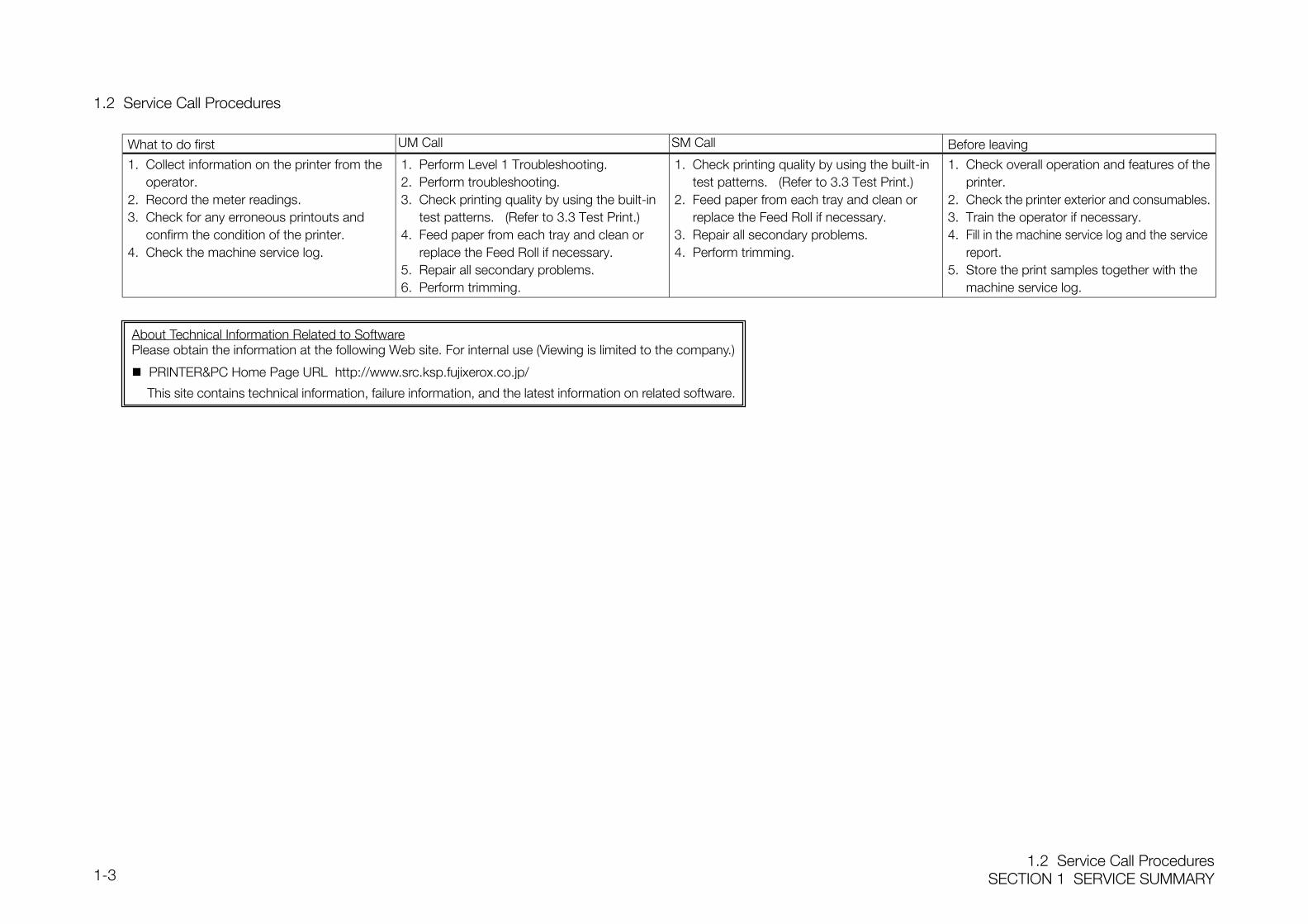
1.2 Service Call ProceduresSECTION 1 SERVICE SUMMARY1-3
1.2 Service Call Procedures
What to do first UM Call SM Call Before leaving
1. Collect information on the printer from theoperator.
2. Record the meter readings.3. Check for any erroneous printouts and
confirm the condition of the printer.4. Check the machine service log.
1. Perform Level 1 Troubleshooting.2. Perform troubleshooting.3. Check printing quality by using the built-in
test patterns. (Refer to 3.3 Test Print.)4. Feed paper from each tray and clean or
replace the Feed Roll if necessary.5. Repair all secondary problems.6. Perform trimming.
1. Check printing quality by using the built-intest patterns. (Refer to 3.3 Test Print.)
2. Feed paper from each tray and clean orreplace the Feed Roll if necessary.
3. Repair all secondary problems.4. Perform trimming.
1. Check overall operation and features of theprinter.
2. Check the printer exterior and consumables.3. Train the operator if necessary.4. Fill in the machine service log and the service
report.5. Store the print samples together with the
machine service log.
About Technical Information Related to SoftwarePlease obtain the information at the following Web site. For internal use (Viewing is limited to the company.)
PRINTER&PC Home Page URL http://www.src.ksp.fujixerox.co.jp/
This site contains technical information, failure information, and the latest information on related software.
SECTION 1 SERVICE SUMMARY1.3 Trimming
1-4
1.3 TrimmingPerform trimming on DocuPrint C1618 at each SM/UM. This helps to maintain optimummachine performance. Performing trimming should not be the primary purpose of any visit.
1.3.1 Trimming Procedures1. Check the overall operation before beginning.
Make prints with a test pattern containing 20% color pattern for each color, gradationpattern and grid pattern.
1. 20% pattern for each color : Checks for any scratches on the IBT Belt and drum,and for fusing failure.
2. Gradation pattern : Checks for improper low-density reproducibility, colorbalance and fusing failure.
3. Grid pattern : Checks for color misalignment and fusing failure.
※ Refer to 3.3 Test Print on how to generate test patterns.
2. Clean the machine interior. Clean up any toner or paper dust in the paper path.
(Particularly in those areas accessed by the operator.)
3. Check replacement parts (consumable parts) regularly and replace them if necessary.
4. Check safety conditions. Check the connection of the power plug and look out for any damage to the cord or
plug.
5. Check the overall operation after trimming. Check machine operation. Check print quality. Check meter readings.
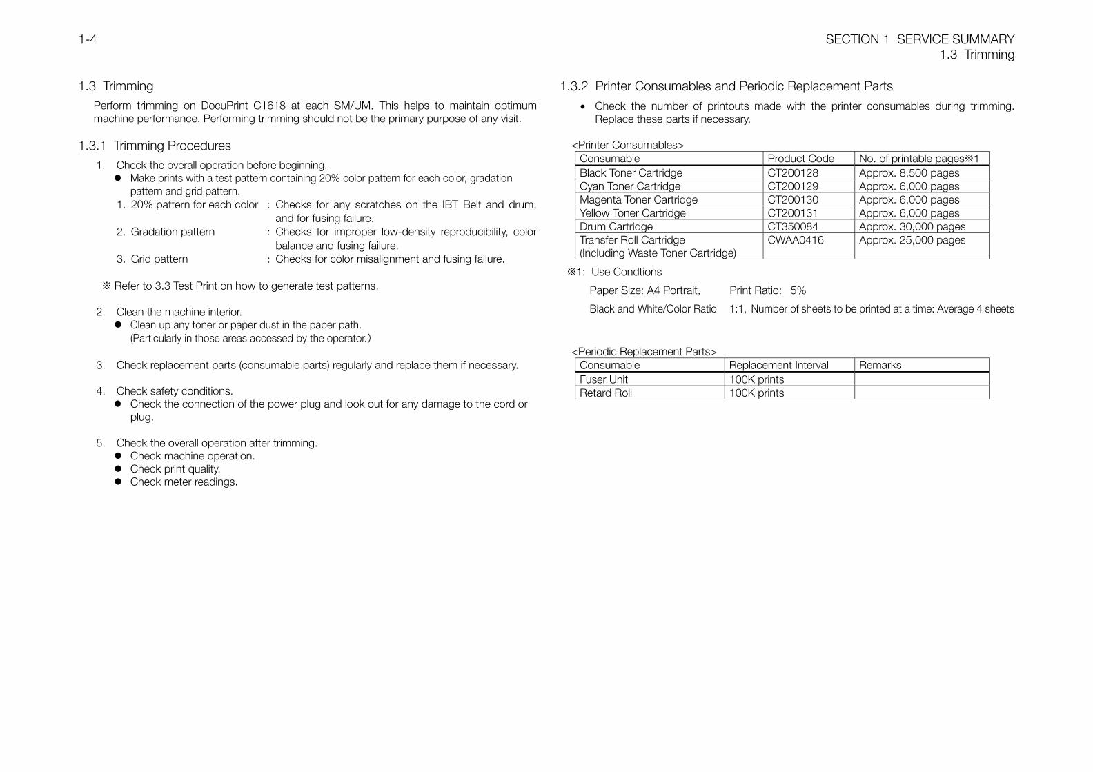
1.3.2 Printer Consumables and Periodic Replacement Parts
• Check the number of printouts made with the printer consumables during trimming.Replace these parts if necessary.
<Printer Consumables>Consumable Product Code No. of printable pages※1Black Toner Cartridge CT200128 Approx. 8,500 pagesCyan Toner Cartridge CT200129 Approx. 6,000 pagesMagenta Toner Cartridge CT200130 Approx. 6,000 pagesYellow Toner Cartridge CT200131 Approx. 6,000 pagesDrum Cartridge CT350084 Approx. 30,000 pagesTransfer Roll Cartridge(Including Waste Toner Cartridge)
CWAA0416 Approx. 25,000 pages
※1: Use Condtions
Paper Size: A4 Portrait, Print Ratio: 5%
Black and White/Color Ratio 1:1, Number of sheets to be printed at a time: Average 4 sheets
<Periodic Replacement Parts>Consumable Replacement Interval RemarksFuser Unit 100K printsRetard Roll 100K prints
1.3 TrimmingSECTION 1 SERVICE SUMMARY1-5
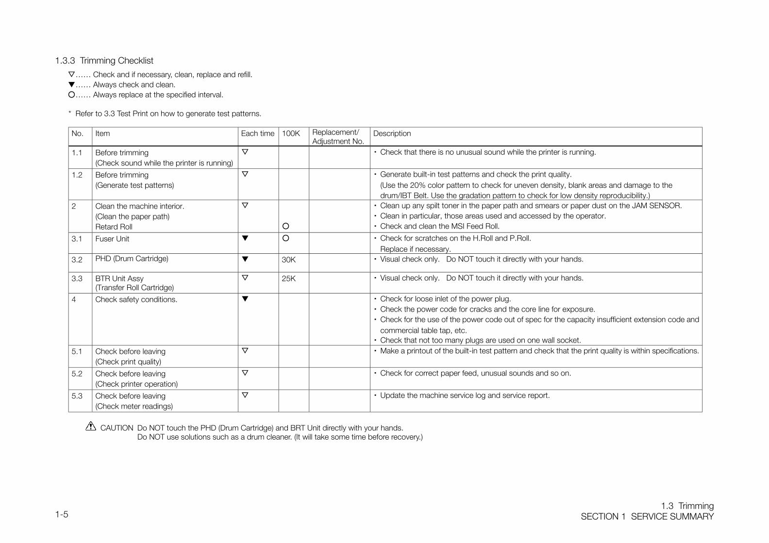
1.3.3 Trimming Checklist
…… Check and if necessary, clean, replace and refill.…… Always check and clean.…… Always replace at the specified interval.
* Refer to 3.3 Test Print on how to generate test patterns.
No. Item Each time 100K Replacement/Adjustment No.
Description
1.1 Before trimming(Check sound while the printer is running)
・ Check that there is no unusual sound while the printer is running.
1.2 Before trimming(Generate test patterns)
・ Generate built-in test patterns and check the print quality.(Use the 20% color pattern to check for uneven density, blank areas and damage to thedrum/IBT Belt. Use the gradation pattern to check for low density reproducibility.)
2 Clean the machine interior.(Clean the paper path)Retard Roll
・ Clean up any spilt toner in the paper path and smears or paper dust on the JAM SENSOR.・ Clean in particular, those areas used and accessed by the operator.・ Check and clean the MSI Feed Roll.
3.1 Fuser Unit ・ Check for scratches on the H.Roll and P.Roll.Replace if necessary.
3.2 PHD (Drum Cartridge) 30K ・ Visual check only. Do NOT touch it directly with your hands.
3.3 BTR Unit Assy(Transfer Roll Cartridge)
25K ・ Visual check only. Do NOT touch it directly with your hands.
4 Check safety conditions. ・ Check for loose inlet of the power plug.・ Check the power code for cracks and the core line for exposure.・ Check for the use of the power code out of spec for the capacity insufficient extension code and
commercial table tap, etc.・ Check that not too many plugs are used on one wall socket.
5.1 Check before leaving(Check print quality)
・ Make a printout of the built-in test pattern and check that the print quality is within specifications.
5.2 Check before leaving(Check printer operation)
・ Check for correct paper feed, unusual sounds and so on.
5.3 Check before leaving(Check meter readings)
・ Update the machine service log and service report.
CAUTION Do NOT touch the PHD (Drum Cartridge) and BRT Unit directly with your hands. Do NOT use solutions such as a drum cleaner. (It will take some time before recovery.)

SECTION 2 TROUBLESHOOTING

ContentsSECTION 2 TROUBLESHOOTING2-1
Contents
2.1 Preface ...................................................................................................................... 3
2.1.1 Troubleshooting Procedures ................................................................................ 3
2.1.2 Precautions while Troubleshooting ....................................................................... 3
2.2 Level 1 Troubleshooting ............................................................................................. 4
2.2.1 Level 1 FIP .......................................................................................................... 4
2.3 Level 2 Troubleshooting ............................................................................................. 5
2.3.1 Failure Code List.................................................................................................. 5
2.3.2 Failure FIPs........................................................................................................ 10
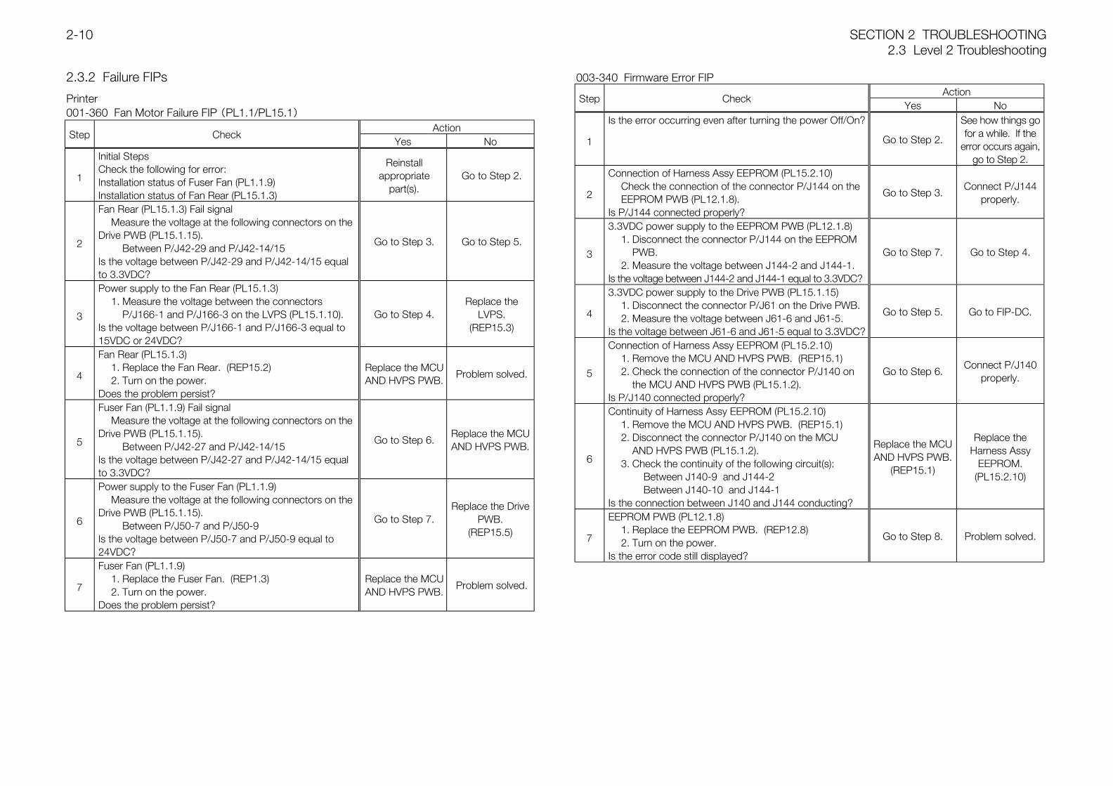
001-360 Fan Motor Failure FIP (PL1.1/PL15.1) ...................................................... 10
003-340 Firmware Error FIP .................................................................................... 10
003-356 NV-RAM Error FIP ..................................................................................... 11
006-370 ROS Failure FIP(PL11.1).......................................................................... 11
009-340 ADC Sensor Error FIP(PL6.1) ................................................................... 12
009-342 Low Density Error FIP ............................................................................... 12
010-317 Fuser Detached FIP .................................................................................. 13
010-350 Fuser Failure FIP(PL9.1) ........................................................................... 14
010-351 Fuser Life Over FIP.................................................................................... 14
010-354 Hum Temp Sensor Error FIP(PL4.2) ......................................................... 15
Duplex JAM FIP ....................................................................................................... 15
Regi JAM FIP ........................................................................................................... 18
Media Type Mismatch FIP ........................................................................................ 24
Yellow Toner Cartridge Detached FIP........................................................................ 25
Magenta Toner Cartridge Detached FIP.................................................................... 26
Cyan Toner Cartridge Detached FIP ......................................................................... 26
Black Toner Cartridge Detached FIP......................................................................... 27
BTR Detached FIP ................................................................................................... 27
PHD Detached FIP................................................................................................... 28
Yellow Toner Empty FIP ............................................................................................ 29
Magenta Toner Empty FIP ........................................................................................ 30
Cyan Toner Empty FIP .............................................................................................. 31
Black Toner Empty FIP ............................................................................................. 32
BTR Life Over FIP..................................................................................................... 33
PHD Life Over FIP .................................................................................................... 34
CRUM ID Error FIP ................................................................................................... 35
ADC Sensor Dustiness FIP ....................................................................................... 36
Front Cover FIP ........................................................................................................ 36
Full Stack FIP ........................................................................................................... 36
Tray1 Paper Near Empty FIP..................................................................................... 37
Tray2 Paper Near Empty FIP..................................................................................... 38
2.4 How to Use Diag. (C/E) Mode .................................................................................. 41
2.4.1 Operation Panel in Diag. (C/E) Mode .................................................................. 41
2.4.2 Entering Diag. (C/E) Mode.................................................................................. 41
2.4.3 Exiting from Diag. (C/E) Mode ............................................................................ 41
2.4.4 Types of Diag. (C/E) Mode.................................................................................. 41
2.4.5 Procedures ........................................................................................................ 42
2.4.6 Diag. Mode Menu Tree....................................................................................... 43
2.4.7 ESS Diagnostics ................................................................................................ 44
2.4.8 IOT Diagnostics ................................................................................................. 45
2.4.8.1 Digital Input Test .......................................................................................... 45
2.4.8.2 Digital Output Test ....................................................................................... 47
2.4.8.3 NVM Read/Write.......................................................................................... 50
2.4.8.4 Print NVM Information ................................................................................. 50
2.4.8.5 Save NVM Information................................................................................. 50
2.4.8.6 Load NVM Information................................................................................. 51
2.4.9 Installation Setup ............................................................................................... 52
2.4.10 Test Print ...................................................................................................... 53
2.4.11 Setting Parameters .......................................................................................... 54
2.4.11.1 Setting/Displaying Parameters ................................................................... 54
2.4.11.2 Print Parameters List ................................................................................. 55
SECTION 2 TROUBLESHOOTINGContents
2-2
2.4.12 Print Information .............................................................................................. 56
2.5 Diag. of the Printer Itself ........................................................................................... 58
2.5.1 Description ........................................................................................................ 58
2.5.2 Making Prints .................................................................................................... 58
2.5.3 Test Print Pattern............................................................................................... 58
2.6 NVM List.................................................................................................................. 59
2.7 HEX-to-DEC Conversion Table................................................................................. 63
ContentsSECTION 2 TROUBLESHOOTING2-3
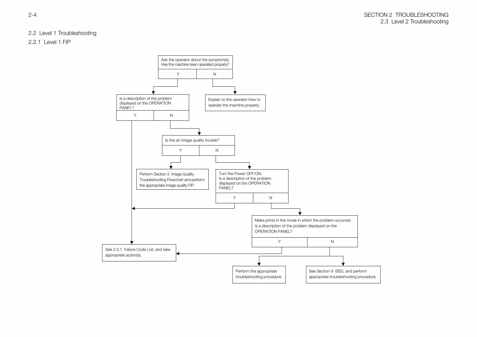
2.1 Preface
2.1.1 Troubleshooting Procedures
The troubleshooting procedures are divided into Level 1and Level 2 Troubleshooting.
Level 1 TroubleshootingCheck failure codes and problem symptoms using theLevel 1 FIPs.
Level 2 TroubleshootingIdentify the cause of a problem using FIP, BSD, and thefailure code list, and recover the machine.
2.1.2 Precautions while Troubleshooting
Before replacing parts, check that any connectors aresecurely connected.
When replacing parts, switch off the power. If there are multiple problems, the same FIP may be
referred to again. In this case, the same FIP may guideyou to different steps.
WARNING While the power is on, do NOT touch thefollowing parts so as to avoid electricshock:
・ HVPS・ LVPS
WARNING While the power is on, the DRUMCARTRIDGE should remain installed.Invisible laser radiation is harmful to youreyes.
WARNING The HEAT ROLL, the PRESSURE ROLL,and their surroundings will be hot. Toavoid burns, do NOT touch them beforethey have cooled off sufficiently.
GlossaryFailure Code:
A code displayed on the OPERATION PANEL when aproblem occurs.
POWER OFF:The state in which the MAIN POWER SWITCH is turnedoff and the POWER CORD is unplugged.
WARNING When POWER OFF is indicated in anytroubleshooting procedure, turn the MAINPOWER SWITCH off and unplug thePOWER CORD to avoid electric shock orpersonal injury.
POWER ON:The state in which the MAIN POWER SWITCH is turnedon.
Cycle the Power Switch:Turn the MAIN POWER SWITCH off and then on again.
Execute [DO-10]:Execute DIAG. Code [DO-10].
End [DO-10]:Stop DIAG. Code [DO-10].
PL4.2:Refer to PL4.2 in Section 5 Parts List.
REP4.1.3:Refer to REP4.1.3 in Section 4.
ADJ4.1.3:Refer to ADJ4.1.3 in Section 4.
+5VDC H Level : +4.1 ~ +5.6VDCL Level : -0.3 ~ +1.2VDC
+24VDC H Level : +21.8 ~ +25.8VDCL Level : -0.4 ~ +3.3VDC
SECTION 2 TROUBLESHOOTING2.3 Level 2 Troubleshooting
2-4
2.2 Level 1 Troubleshooting
2.2.1 Level 1 FIP
Ask the operator about the symptom(s).Has the machine been operated properly?
Y N
Explain to the operator how tooperate the machine properly.
Is a description of the problemdisplayed on the OPERATIONPANEL?
Y N
Is this an image quality trouble?
Y N
Perform Section 3 Image QualityTroubleshooting Flowchart and performthe appropriate image quality FIP.
Turn the Power OFF/ON.Is a description of the problemdisplayed on the OPERATIONPANEL?
Y N
Make prints in the mode in which the problem occurred.Is a description of the problem displayed on theOPERATION PANEL?
Y N
Perform the appropriatetroubleshooting procedure.
See Section 9 BSD, and performappropriate troubleshooting procedure.
See 2.3.1 Failure Code List, and takeappropriate action(s).
2.3 Level 2 TroubleshootingSECTION 2 TROUBLESHOOTING2-5
2.3 Level 2 Troubleshooting
2.3.1 Failure Code List
LCD <Failed Items>Trouble Description
Corrective Measures ReferenceBSD
001-360 Reboot Printer <IOT Fan Motor Failure>Detection of fail signal of either FUSER FAN or REAR FAN.
Cycle the power.Refer to Fan Motor Failure FIP.
CH 10.3CH 10.6
003-340 Reboot the Printer <IOT Firmware Error>IOT Firmware error
Cycle the power.Refer to Firmware Error FIP.
CH 3.1CH 3.3
003-356 Reboot the Printer <IOT NVRAM Error>NVRAM error.
Cycle the power.Refer to NV-RAM Error FIP.
CH 3.1CH 3.3
006-370 Reboot the Printer <IOT ROS Failure>1. The Laser power is down.2. The SOS signal cannot be detected.
Cycle the power.Refer to ROS Failure FIP.
CH 6.1CH 6.2
009-340 Reboot the Printer <IOT ADC Sensor Error>The ADC SENSOR ASSY power is down.
Cycle the power.Refer to ADC Sensor Error FIP.
CH 9.7CH 9.8
009-342 Reboot the Printer <IOT Low Density Error>The toner density is low.
Cycle the power.Refer to Low Density Error FIP.
CH 9.7CH 9.8
010-317 Reboot the Printer <IOT Fuser Detached>It was detected that the FUSER ASSY 100V was not installed.
Cycle the power.Refer to Fuser Detached FIP.
CH 10.1CH 10.6
010-350 Reboot the Printer <IOT Fuser Failure>1. The temperature was detected to be exceeding 35°C 4 times consecutively.2. The temperature was detected to be below 120°C 4 times consecutively.3. The resistance value of the STS Sensor was detected to have exceeded 2437KΩ 4 times
consecutively.4. The Fuser Lamp does not reach the target temperature after more than 60sec has passed
after lit on.5. After the target temperature is reached, the Fuser Lamp continued to be lit after the
specified time.6. The STS Sensor value does not change after the Lamp is lit.7. The temperature was detected to be exceeding 230°C 2 times consecutively during
printing.
Cycle the power.Refer to Fuser Failure FIP.
CH 10.1CH 10.6
010-351 Reboot the Printer <IOT Fuser Life Over>Life of the FUSER ASSY 100V.
Cycle the power.Refer to Fuser Life Over FIP.
CH 3.1CH 3.3
010-354 Reboot the Printer <IOT Hum Temp Sensor Error>1. The temperature was detected to be higher than 100°C or lower than -20°C.2. The humidity was detected to be higher than 100%.
Cycle the power.Refer to Hum Temp Sensor Error FIP.
CH 9.7CH 9.8
016-300 Reboot the Printer <ESS Data Cache Error>CPU Data Cache Error
Cycle the power. CH 3.1CH 3.3
016-301 Reboot the Printer <ESS Instruction Cache Error>CPU Instruction Cache Error
Cycle the power. CH 3.1CH 3.3
016-302 Reboot the Printer <ESS Illegal Exception>CPU Illegal Exception
Cycle the power. CH 3.1CH 3.3
016-317 Reboot the Printer <ESS ROM Check (Main) Error>Main Program ROM Checksum error.
Cycle the power. CH 3.1CH 3.3
SECTION 2 TROUBLESHOOTING2.3 Level 2 Troubleshooting
2-6
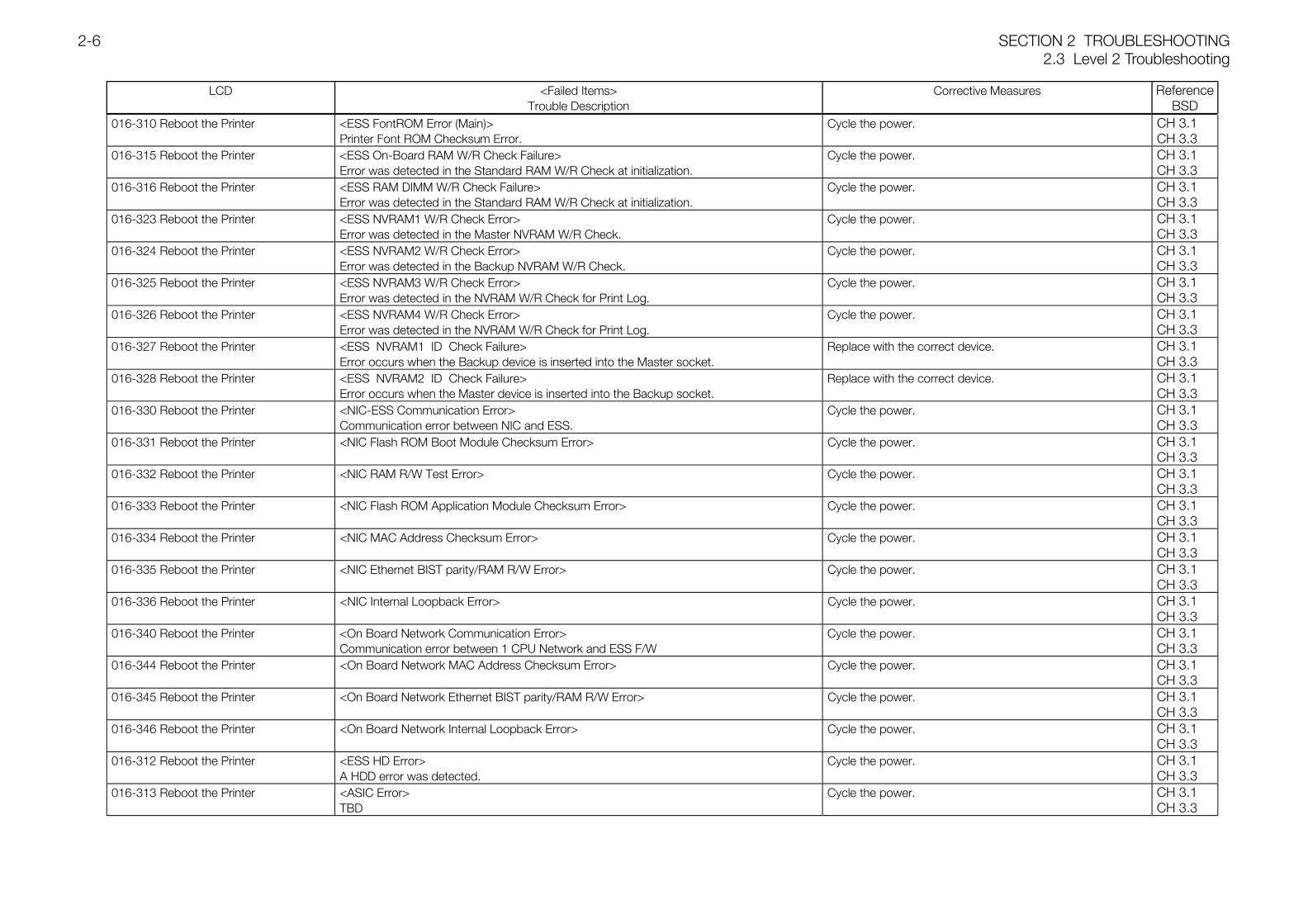
LCD <Failed Items>Trouble Description
Corrective Measures ReferenceBSD
016-310 Reboot the Printer <ESS FontROM Error (Main)>Printer Font ROM Checksum Error.
Cycle the power. CH 3.1CH 3.3
016-315 Reboot the Printer <ESS On-Board RAM W/R Check Failure>Error was detected in the Standard RAM W/R Check at initialization.
Cycle the power. CH 3.1CH 3.3
016-316 Reboot the Printer <ESS RAM DIMM W/R Check Failure>Error was detected in the Standard RAM W/R Check at initialization.
Cycle the power. CH 3.1CH 3.3
016-323 Reboot the Printer <ESS NVRAM1 W/R Check Error>Error was detected in the Master NVRAM W/R Check.
Cycle the power. CH 3.1CH 3.3
016-324 Reboot the Printer <ESS NVRAM2 W/R Check Error>Error was detected in the Backup NVRAM W/R Check.
Cycle the power. CH 3.1CH 3.3
016-325 Reboot the Printer <ESS NVRAM3 W/R Check Error>Error was detected in the NVRAM W/R Check for Print Log.
Cycle the power. CH 3.1CH 3.3
016-326 Reboot the Printer <ESS NVRAM4 W/R Check Error>Error was detected in the NVRAM W/R Check for Print Log.
Cycle the power. CH 3.1CH 3.3
016-327 Reboot the Printer <ESS NVRAM1 ID Check Failure>Error occurs when the Backup device is inserted into the Master socket.
Replace with the correct device. CH 3.1CH 3.3
016-328 Reboot the Printer <ESS NVRAM2 ID Check Failure>Error occurs when the Master device is inserted into the Backup socket.
Replace with the correct device. CH 3.1CH 3.3
016-330 Reboot the Printer <NIC-ESS Communication Error>Communication error between NIC and ESS.
Cycle the power. CH 3.1CH 3.3
016-331 Reboot the Printer <NIC Flash ROM Boot Module Checksum Error> Cycle the power. CH 3.1CH 3.3
016-332 Reboot the Printer <NIC RAM R/W Test Error> Cycle the power. CH 3.1CH 3.3
016-333 Reboot the Printer <NIC Flash ROM Application Module Checksum Error> Cycle the power. CH 3.1CH 3.3
016-334 Reboot the Printer <NIC MAC Address Checksum Error> Cycle the power. CH 3.1CH 3.3
016-335 Reboot the Printer <NIC Ethernet BIST parity/RAM R/W Error> Cycle the power. CH 3.1CH 3.3
016-336 Reboot the Printer <NIC Internal Loopback Error> Cycle the power. CH 3.1CH 3.3
016-340 Reboot the Printer <On Board Network Communication Error>Communication error between 1 CPU Network and ESS F/W
Cycle the power. CH 3.1CH 3.3
016-344 Reboot the Printer <On Board Network MAC Address Checksum Error> Cycle the power. CH 3.1CH 3.3
016-345 Reboot the Printer <On Board Network Ethernet BIST parity/RAM R/W Error> Cycle the power. CH 3.1CH 3.3
016-346 Reboot the Printer <On Board Network Internal Loopback Error> Cycle the power. CH 3.1CH 3.3
016-312 Reboot the Printer <ESS HD Error>A HDD error was detected.
Cycle the power. CH 3.1CH 3.3
016-313 Reboot the Printer <ASIC Error>TBD
Cycle the power. CH 3.1CH 3.3
2.3 Level 2 TroubleshootingSECTION 2 TROUBLESHOOTING2-7
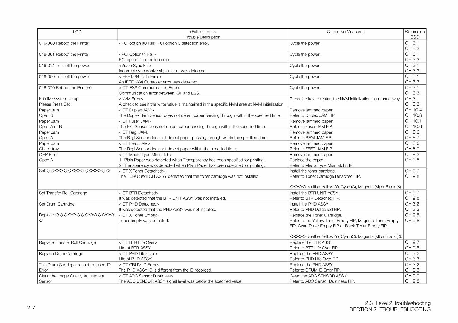
LCD <Failed Items>Trouble Description
Corrective Measures ReferenceBSD
016-360 Reboot the Printer <PCI option #0 Fail> PCI option 0 detection error. Cycle the power. CH 3.1CH 3.3
016-361 Reboot the Printer <PCI Option#1 Fail>PCI option 1 detection error.
Cycle the power. CH 3.1CH 3.3
016-314 Turn off the power <Video Sync Fail>Incorrect synchronize signal input was detected.
Cycle the power. CH 3.1CH 3.3
016-350 Turn off the power <IEEE1284 Data Error>An IEEE1284 Controller error was detected.
Cycle the power. CH 3.1CH 3.3
016-370 Reboot the Printer0 <IOT-ESS Communication Error>Communication error between IOT and ESS.
Cycle the power. CH 3.1CH 3.3
Initialize system setupPlease Press Set
<NVM Error>A check to see if the write value is maintained in the specific NVM area at NVM initialization.
Press the key to restart the NVM initialization in an usual way. CH 3.1CH 3.3
Paper JamOpen B
<IOT Duplex JAM>The Duplex Jam Sensor does not detect paper passing through within the specified time.
Remove jammed paper.Refer to Duplex JAM FIP.
CH 10.4CH 10.6
Paper JamOpen A or B
<IOT Fuser JAM>The Exit Sensor does not detect paper passing through within the specified time.
Remove jammed paper.Refer to Fuser JAM FIP.
CH 10.1CH 10.6
Paper JamOpen A
<IOT Regi JAM>The Regi Sensor does not detect paper passing through within the specified time.
Remove jammed paper.Refer to REGI JAM FIP.
CH 8.6CH 8.7
Paper JamCheck tray
<IOT Feed JAM>The Regi Sensor does not detect paper within the specified time.
Remove jammed paper.Refer to FEED JAM FIP.
CH 8.6CH 8.7
OHP ErrorOpen A
<IOT Media Type Mismatch>1. Plain Paper was detected when Transparency has been specified for printing.2. Transparency was detected when Plain Paper has been specified for printing.
Remove jammed paper.Replace the paper.Refer to Media Type Mismatch FIP.
CH 9.3CH 9.8
Set <IOT X Toner Detached>The TCRU SWITCH ASSY detected that the toner cartridge was not installed.
Install the toner cartridge.Refer to Toner Cartridge Detached FIP.
is either Yellow (Y), Cyan (C), Magenta (M) or Black (K).
CH 9.7CH 9.8
Set Transfer Roll Cartridge <IOT BTR Detached>It was detected that the BTR UNIT ASSY was not installed.
Install the BTR UNIT ASSY.Refer to BTR Detached FIP.
CH 9.7CH 9.8
Set Drum Cartridge <IOT PHD Detached>It was detected that the PHD ASSY was not installed.
Install the PHD ASSY.Refer to PHD Detached FIP.
CH 3.2CH 3.3
Replace
<IOT X Toner Empty>Toner empty was detected.
Replace the Toner Cartridge.Refer to the Yellow Toner Empty FIP, Magenta Toner EmptyFIP, Cyan Toner Empty FIP or Black Toner Empty FIP.
is either Yellow (Y), Cyan (C), Magenta (M) or Black (K).
CH 9.5CH 9.8
Replace Transfer Roll Cartridge <IOT BTR Life Over>Life of BTR ASSY.
Replace the BTR ASSY.Refer to BTR Life Over FIP.
CH 9.7CH 9.8
Replace Drum Cartridge <IOT PHD Life Over>Life of PHD ASSY.
Replace the PHD ASSY.Refer to PHD Life Over FIP.
CH 3.2CH 3.3
This Drum Cartridge cannot be used-IDError
<IOT CRUM ID Error>The PHD ASSY ID is different from the ID recorded.
Replace the PHD ASSY.Refer to CRUM ID Error FIP.
CH 3.2CH 3.3
Clean the Image Quality AdjustmentSensor
<IOT ADC Sensor Dustiness>The ADC SENSOR ASSY signal level was below the specified value.
Clean the ADC SENSOR ASSY.Refer to ADC Sensor Dustiness FIP.
CH 9.7CH 9.8
SECTION 2 TROUBLESHOOTING2.3 Level 2 Troubleshooting
2-8
LCD <Failed Items>Trouble Description
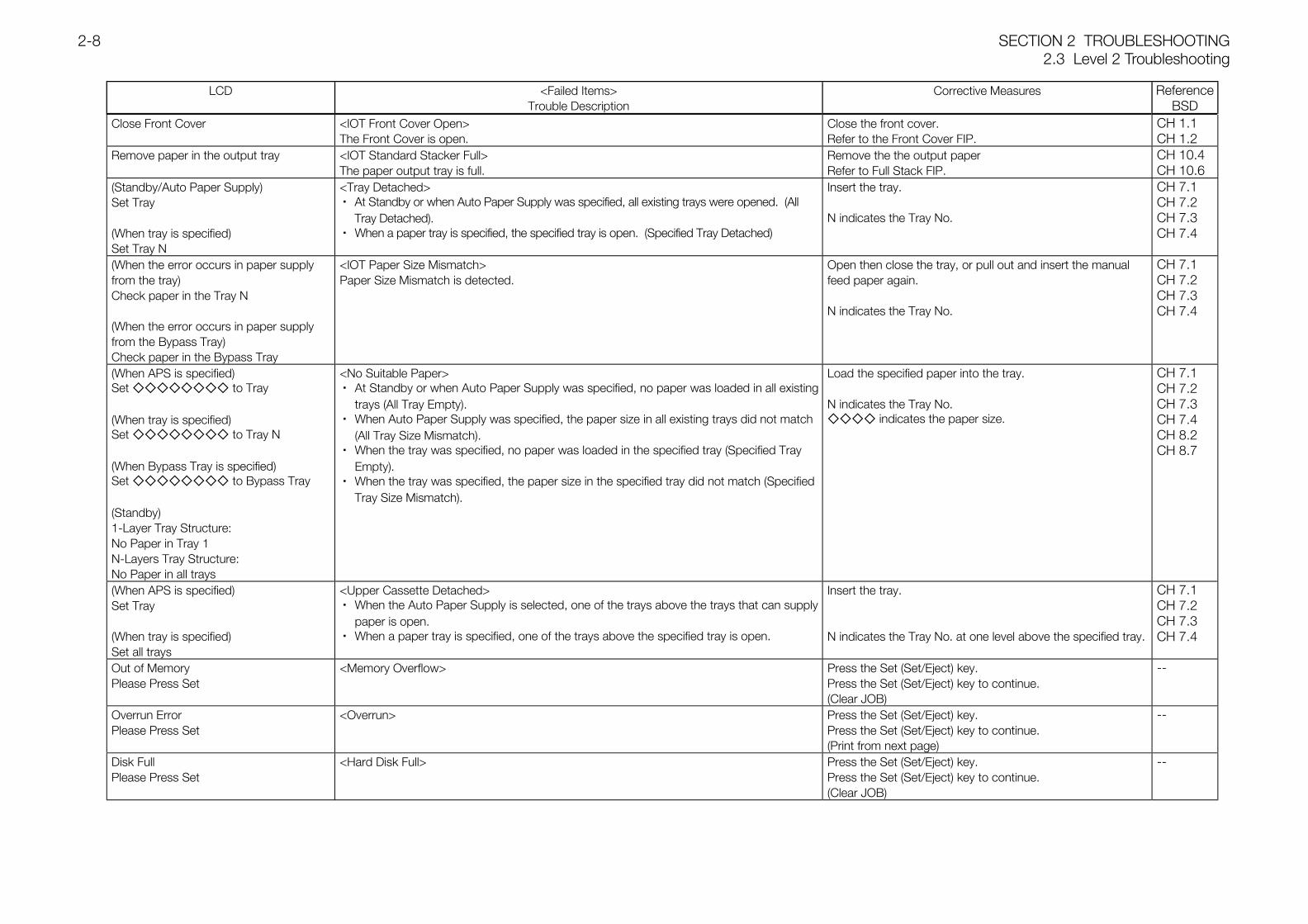
Corrective Measures ReferenceBSD
Close Front Cover <IOT Front Cover Open>The Front Cover is open.
Close the front cover.Refer to the Front Cover FIP.
CH 1.1CH 1.2
Remove paper in the output tray <IOT Standard Stacker Full>The paper output tray is full.
Remove the the output paperRefer to Full Stack FIP.
CH 10.4CH 10.6
(Standby/Auto Paper Supply)Set Tray
(When tray is specified)Set Tray N
<Tray Detached>・ At Standby or when Auto Paper Supply was specified, all existing trays were opened. (All
Tray Detached).・ When a paper tray is specified, the specified tray is open. (Specified Tray Detached)
Insert the tray.
N indicates the Tray No.
CH 7.1CH 7.2CH 7.3CH 7.4
(When the error occurs in paper supplyfrom the tray)Check paper in the Tray N
(When the error occurs in paper supplyfrom the Bypass Tray)Check paper in the Bypass Tray
<IOT Paper Size Mismatch>Paper Size Mismatch is detected.
Open then close the tray, or pull out and insert the manualfeed paper again.
N indicates the Tray No.
CH 7.1CH 7.2CH 7.3CH 7.4
(When APS is specified)Set to Tray
(When tray is specified)Set to Tray N
(When Bypass Tray is specified)Set to Bypass Tray
(Standby)1-Layer Tray Structure:No Paper in Tray 1N-Layers Tray Structure:No Paper in all trays
<No Suitable Paper>・ At Standby or when Auto Paper Supply was specified, no paper was loaded in all existing
trays (All Tray Empty).・ When Auto Paper Supply was specified, the paper size in all existing trays did not match
(All Tray Size Mismatch).・ When the tray was specified, no paper was loaded in the specified tray (Specified Tray
Empty).・ When the tray was specified, the paper size in the specified tray did not match (Specified
Tray Size Mismatch).
Load the specified paper into the tray.
N indicates the Tray No. indicates the paper size.
CH 7.1CH 7.2CH 7.3CH 7.4CH 8.2CH 8.7
(When APS is specified)Set Tray
(When tray is specified)Set all trays
<Upper Cassette Detached>・ When the Auto Paper Supply is selected, one of the trays above the trays that can supply
paper is open.・ When a paper tray is specified, one of the trays above the specified tray is open.
Insert the tray.
N indicates the Tray No. at one level above the specified tray.
CH 7.1CH 7.2CH 7.3CH 7.4
Out of MemoryPlease Press Set
<Memory Overflow> Press the Set (Set/Eject) key.Press the Set (Set/Eject) key to continue.(Clear JOB)
--
Overrun ErrorPlease Press Set
<Overrun> Press the Set (Set/Eject) key.Press the Set (Set/Eject) key to continue.(Print from next page)
--
Disk FullPlease Press Set
<Hard Disk Full> Press the Set (Set/Eject) key.Press the Set (Set/Eject) key to continue.(Clear JOB)
--
2.3 Level 2 TroubleshootingSECTION 2 TROUBLESHOOTING2-9
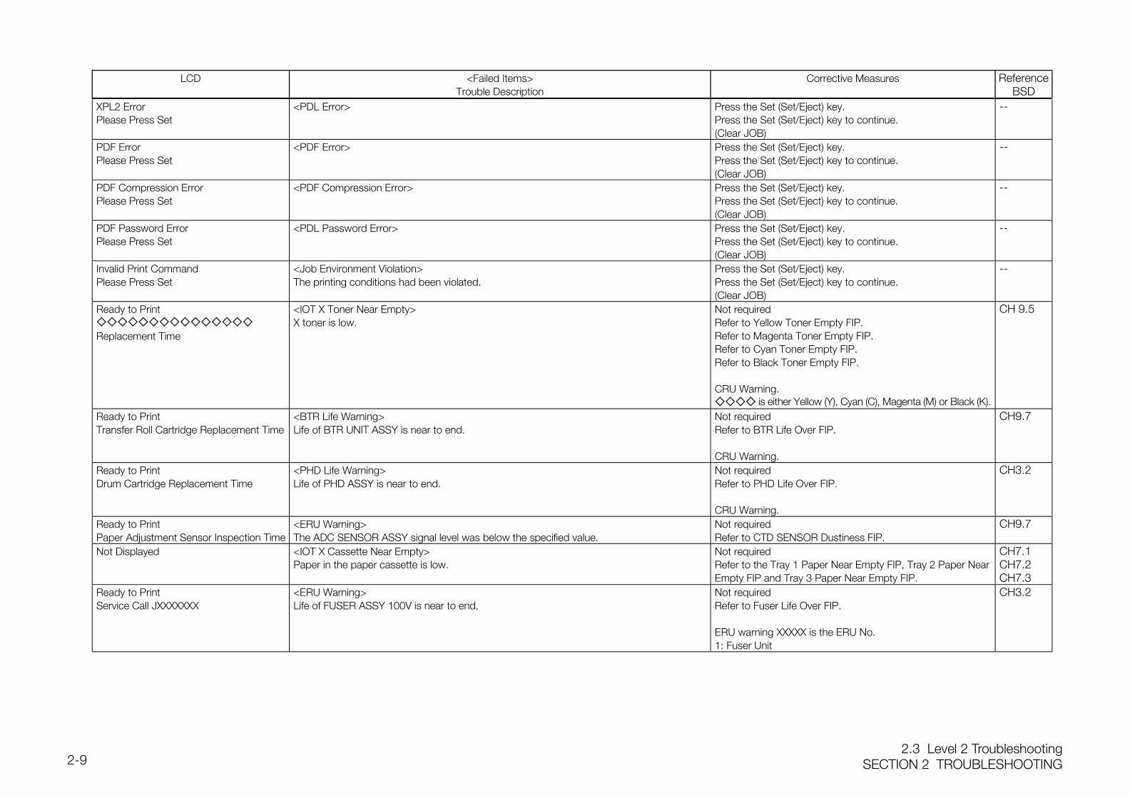
LCD <Failed Items>Trouble Description
Corrective Measures ReferenceBSD
XPL2 ErrorPlease Press Set
<PDL Error> Press the Set (Set/Eject) key.Press the Set (Set/Eject) key to continue.(Clear JOB)
--
PDF ErrorPlease Press Set
<PDF Error> Press the Set (Set/Eject) key.Press the Set (Set/Eject) key to continue.(Clear JOB)
--
PDF Compression ErrorPlease Press Set
<PDF Compression Error> Press the Set (Set/Eject) key.Press the Set (Set/Eject) key to continue.(Clear JOB)
--
PDF Password ErrorPlease Press Set
<PDL Password Error> Press the Set (Set/Eject) key.Press the Set (Set/Eject) key to continue.(Clear JOB)
--
Invalid Print CommandPlease Press Set
<Job Environment Violation>The printing conditions had been violated.
Press the Set (Set/Eject) key.Press the Set (Set/Eject) key to continue.(Clear JOB)
--
Ready to Print
Replacement Time
<IOT X Toner Near Empty>X toner is low.
Not requiredRefer to Yellow Toner Empty FIP.Refer to Magenta Toner Empty FIP.Refer to Cyan Toner Empty FIP.Refer to Black Toner Empty FIP.
CRU Warning. is either Yellow (Y), Cyan (C), Magenta (M) or Black (K).
CH 9.5
Ready to PrintTransfer Roll Cartridge Replacement Time
<BTR Life Warning>Life of BTR UNIT ASSY is near to end.
Not requiredRefer to BTR Life Over FIP.
CRU Warning.
CH9.7
Ready to PrintDrum Cartridge Replacement Time
<PHD Life Warning>Life of PHD ASSY is near to end.
Not requiredRefer to PHD Life Over FIP.
CRU Warning.
CH3.2
Ready to PrintPaper Adjustment Sensor Inspection Time
<ERU Warning>The ADC SENSOR ASSY signal level was below the specified value.
Not requiredRefer to CTD SENSOR Dustiness FIP.
CH9.7
Not Displayed <IOT X Cassette Near Empty>Paper in the paper cassette is low.
Not requiredRefer to the Tray 1 Paper Near Empty FIP, Tray 2 Paper NearEmpty FIP and Tray 3 Paper Near Empty FIP.
CH7.1CH7.2CH7.3
Ready to PrintService Call JXXXXXXX
<ERU Warning>Life of FUSER ASSY 100V is near to end.
Not requiredRefer to Fuser Life Over FIP.
ERU warning XXXXX is the ERU No.1: Fuser Unit
CH3.2
SECTION 2 TROUBLESHOOTING2.3 Level 2 Troubleshooting
2-10
2.3.2 Failure FIPs
Printer001-360 Fan Motor Failure FIP (PL1.1/PL15.1)
ActionStep Check
Yes No
1
Initial StepsCheck the following for error:Installation status of Fuser Fan (PL1.1.9)Installation status of Fan Rear (PL15.1.3)
Reinstallappropriate
part(s).Go to Step 2.
2
Fan Rear (PL15.1.3) Fail signalMeasure the voltage at the following connectors on the
Drive PWB (PL15.1.15).Between P/J42-29 and P/J42-14/15
Is the voltage between P/J42-29 and P/J42-14/15 equalto 3.3VDC?
Go to Step 3. Go to Step 5.
3
Power supply to the Fan Rear (PL15.1.3)1. Measure the voltage between the connectors
P/J166-1 and P/J166-3 on the LVPS (PL15.1.10).Is the voltage between P/J166-1 and P/J166-3 equal to15VDC or 24VDC?
Go to Step 4.Replace the
LVPS.(REP15.3)
4
Fan Rear (PL15.1.3)1. Replace the Fan Rear. (REP15.2)2. Turn on the power.
Does the problem persist?
Replace the MCUAND HVPS PWB.
Problem solved.
5
Fuser Fan (PL1.1.9) Fail signalMeasure the voltage at the following connectors on the
Drive PWB (PL15.1.15).Between P/J42-27 and P/J42-14/15
Is the voltage between P/J42-27 and P/J42-14/15 equalto 3.3VDC?
Go to Step 6.Replace the MCUAND HVPS PWB.
6
Power supply to the Fuser Fan (PL1.1.9)Measure the voltage at the following connectors on the
Drive PWB (PL15.1.15).Between P/J50-7 and P/J50-9
Is the voltage between P/J50-7 and P/J50-9 equal to24VDC?
Go to Step 7.Replace the Drive
PWB.(REP15.5)
7
Fuser Fan (PL1.1.9)1. Replace the Fuser Fan. (REP1.3)2. Turn on the power.
Does the problem persist?
Replace the MCUAND HVPS PWB.
Problem solved.
003-340 Firmware Error FIPAction
Step CheckYes No
1
Is the error occurring even after turning the power Off/On?
Go to Step 2.
See how things gofor a while. If the
error occurs again,go to Step 2.
2
Connection of Harness Assy EEPROM (PL15.2.10)Check the connection of the connector P/J144 on the EEPROM PWB (PL12.1.8).
Is P/J144 connected properly?
Go to Step 3.Connect P/J144
properly.
3
3.3VDC power supply to the EEPROM PWB (PL12.1.8) 1. Disconnect the connector P/J144 on the EEPROM
PWB. 2. Measure the voltage between J144-2 and J144-1.Is the voltage between J144-2 and J144-1 equal to 3.3VDC?
Go to Step 7. Go to Step 4.
4
3.3VDC power supply to the Drive PWB (PL15.1.15) 1. Disconnect the connector P/J61 on the Drive PWB. 2. Measure the voltage between J61-6 and J61-5.Is the voltage between J61-6 and J61-5 equal to 3.3VDC?
Go to Step 5. Go to FIP-DC.
5
Connection of Harness Assy EEPROM (PL15.2.10) 1. Remove the MCU AND HVPS PWB. (REP15.1) 2. Check the connection of the connector P/J140 on
the MCU AND HVPS PWB (PL15.1.2).Is P/J140 connected properly?
Go to Step 6.Connect P/J140
properly.
6
Continuity of Harness Assy EEPROM (PL15.2.10) 1. Remove the MCU AND HVPS PWB. (REP15.1) 2. Disconnect the connector P/J140 on the MCU
AND HVPS PWB (PL15.1.2). 3. Check the continuity of the following circuit(s):
Between J140-9 and J144-2Between J140-10 and J144-1
Is the connection between J140 and J144 conducting?
Replace the MCUAND HVPS PWB.
(REP15.1)
Replace theHarness Assy
EEPROM.(PL15.2.10)
7
EEPROM PWB (PL12.1.8) 1. Replace the EEPROM PWB. (REP12.8) 2. Turn on the power.Is the error code still displayed?
Go to Step 8. Problem solved.
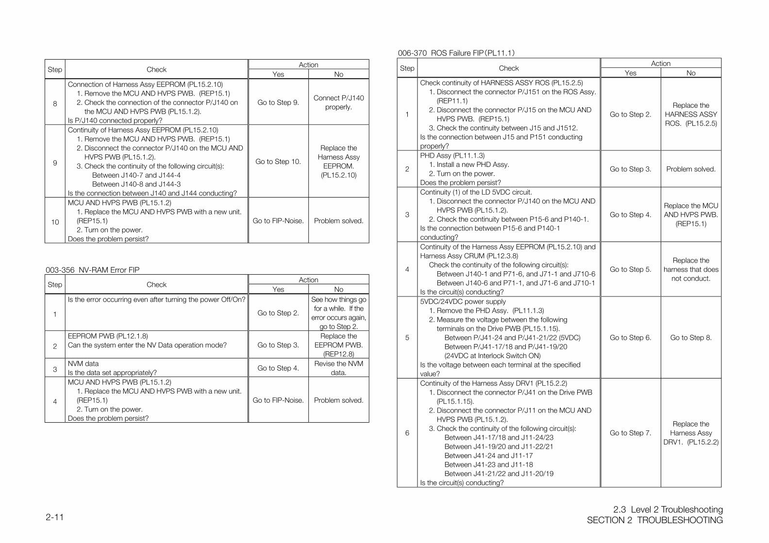
2.3 Level 2 TroubleshootingSECTION 2 TROUBLESHOOTING2-11
ActionStep Check
Yes No
8
Connection of Harness Assy EEPROM (PL15.2.10) 1. Remove the MCU AND HVPS PWB. (REP15.1) 2. Check the connection of the connector P/J140 on
the MCU AND HVPS PWB (PL15.1.2).Is P/J140 connected properly?
Go to Step 9.Connect P/J140
properly.
9
Continuity of Harness Assy EEPROM (PL15.2.10) 1. Remove the MCU AND HVPS PWB. (REP15.1) 2. Disconnect the connector P/J140 on the MCU AND
HVPS PWB (PL15.1.2). 3. Check the continuity of the following circuit(s):
Between J140-7 and J144-4Between J140-8 and J144-3
Is the connection between J140 and J144 conducting?
Go to Step 10.
Replace theHarness Assy
EEPROM.(PL15.2.10)
10
MCU AND HVPS PWB (PL15.1.2) 1. Replace the MCU AND HVPS PWB with a new unit.
(REP15.1) 2. Turn on the power.Does the problem persist?
Go to FIP-Noise. Problem solved.
003-356 NV-RAM Error FIPAction
Step CheckYes No
1
Is the error occurring even after turning the power Off/On?
Go to Step 2.
See how things gofor a while. If the
error occurs again,go to Step 2.
2EEPROM PWB (PL12.1.8)Can the system enter the NV Data operation mode? Go to Step 3.
Replace theEEPROM PWB.
(REP12.8)
3NVM dataIs the data set appropriately?
Go to Step 4.Revise the NVM
data.
4
MCU AND HVPS PWB (PL15.1.2) 1. Replace the MCU AND HVPS PWB with a new unit.
(REP15.1) 2. Turn on the power.Does the problem persist?
Go to FIP-Noise. Problem solved.
006-370 ROS Failure FIP(PL11.1)Action
Step CheckYes No
1
Check continuity of HARNESS ASSY ROS (PL15.2.5)1. Disconnect the connector P/J151 on the ROS Assy.
(REP11.1)2. Disconnect the connector P/J15 on the MCU AND
HVPS PWB. (REP15.1)3. Check the continuity between J15 and J1512.
Is the connection between J15 and P151 conductingproperly?
Go to Step 2.Replace the
HARNESS ASSYROS. (PL15.2.5)
2
PHD Assy (PL11.1.3)1. Install a new PHD Assy.2. Turn on the power.
Does the problem persist?
Go to Step 3. Problem solved.
3
Continuity (1) of the LD 5VDC circuit.1. Disconnect the connector P/J140 on the MCU AND
HVPS PWB (PL15.1.2).2. Check the continuity between P15-6 and P140-1.
Is the connection between P15-6 and P140-1conducting?
Go to Step 4.Replace the MCUAND HVPS PWB.
(REP15.1)
4
Continuity of the Harness Assy EEPROM (PL15.2.10) andHarness Assy CRUM (PL12.3.8)
Check the continuity of the following circuit(s):Between J140-1 and P71-6, and J71-1 and J710-6Between J140-6 and P71-1, and J71-6 and J710-1
Is the circuit(s) conducting?
Go to Step 5.Replace the
harness that doesnot conduct.
5
5VDC/24VDC power supply1. Remove the PHD Assy. (PL11.1.3)2. Measure the voltage between the following
terminals on the Drive PWB (PL15.1.15).Between P/J41-24 and P/J41-21/22 (5VDC)Between P/J41-17/18 and P/J41-19/20 (24VDC at Interlock Switch ON)
Is the voltage between each terminal at the specifiedvalue?
Go to Step 6. Go to Step 8.
6
Continuity of the Harness Assy DRV1 (PL15.2.2)1. Disconnect the connector P/J41 on the Drive PWB
(PL15.1.15).2. Disconnect the connector P/J11 on the MCU AND
HVPS PWB (PL15.1.2).3. Check the continuity of the following circuit(s):
Between J41-17/18 and J11-24/23Between J41-19/20 and J11-22/21Between J41-24 and J11-17Between J41-23 and J11-18Between J41-21/22 and J11-20/19
Is the circuit(s) conducting?
Go to Step 7.Replace the
Harness AssyDRV1. (PL15.2.2)
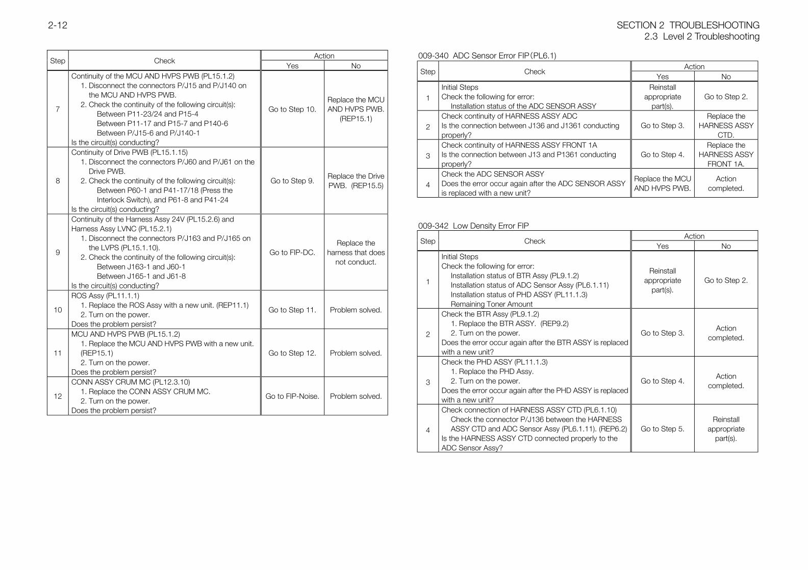
SECTION 2 TROUBLESHOOTING2.3 Level 2 Troubleshooting
2-12
ActionStep Check
Yes No
7
Continuity of the MCU AND HVPS PWB (PL15.1.2)1. Disconnect the connectors P/J15 and P/J140 on
the MCU AND HVPS PWB.2. Check the continuity of the following circuit(s):
Between P11-23/24 and P15-4Between P11-17 and P15-7 and P140-6Between P/J15-6 and P/J140-1
Is the circuit(s) conducting?
Go to Step 10.Replace the MCUAND HVPS PWB.
(REP15.1)
8
Continuity of Drive PWB (PL15.1.15)1. Disconnect the connectors P/J60 and P/J61 on the
Drive PWB.2. Check the continuity of the following circuit(s):
Between P60-1 and P41-17/18 (Press the Interlock Switch), and P61-8 and P41-24
Is the circuit(s) conducting?
Go to Step 9.Replace the DrivePWB. (REP15.5)
9
Continuity of the Harness Assy 24V (PL15.2.6) andHarness Assy LVNC (PL15.2.1)
1. Disconnect the connectors P/J163 and P/J165 on the LVPS (PL15.1.10).
2. Check the continuity of the following circuit(s):Between J163-1 and J60-1Between J165-1 and J61-8
Is the circuit(s) conducting?
Go to FIP-DC.Replace the
harness that doesnot conduct.
10
ROS Assy (PL11.1.1)1. Replace the ROS Assy with a new unit. (REP11.1)2. Turn on the power.
Does the problem persist?
Go to Step 11. Problem solved.
11
MCU AND HVPS PWB (PL15.1.2)1. Replace the MCU AND HVPS PWB with a new unit. (REP15.1)2. Turn on the power.
Does the problem persist?
Go to Step 12. Problem solved.
12
CONN ASSY CRUM MC (PL12.3.10)1. Replace the CONN ASSY CRUM MC.2. Turn on the power.
Does the problem persist?
Go to FIP-Noise. Problem solved.
009-340 ADC Sensor Error FIP(PL6.1)Action
Step CheckYes No
1Initial StepsCheck the following for error:
Installation status of the ADC SENSOR ASSY
Reinstallappropriate
part(s).Go to Step 2.
2Check continuity of HARNESS ASSY ADCIs the connection between J136 and J1361 conductingproperly?
Go to Step 3.Replace the
HARNESS ASSYCTD.
3Check continuity of HARNESS ASSY FRONT 1AIs the connection between J13 and P1361 conductingproperly?
Go to Step 4.Replace the
HARNESS ASSYFRONT 1A.
4Check the ADC SENSOR ASSYDoes the error occur again after the ADC SENSOR ASSYis replaced with a new unit?
Replace the MCUAND HVPS PWB.
Actioncompleted.
009-342 Low Density Error FIPAction
Step CheckYes No
1
Initial StepsCheck the following for error:
Installation status of BTR Assy (PL9.1.2)Installation status of ADC Sensor Assy (PL6.1.11)Installation status of PHD ASSY (PL11.1.3)Remaining Toner Amount
Reinstallappropriate
part(s).Go to Step 2.
2
Check the BTR Assy (PL9.1.2)1. Replace the BTR ASSY. (REP9.2)2. Turn on the power.
Does the error occur again after the BTR ASSY is replacedwith a new unit?
Go to Step 3.Action
completed.
3
Check the PHD ASSY (PL11.1.3)1. Replace the PHD Assy.2. Turn on the power.
Does the error occur again after the PHD ASSY is replacedwith a new unit?
Go to Step 4.Action
completed.
4
Check connection of HARNESS ASSY CTD (PL6.1.10)Check the connector P/J136 between the HARNESS ASSY CTD and ADC Sensor Assy (PL6.1.11). (REP6.2)
Is the HARNESS ASSY CTD connected properly to theADC Sensor Assy?
Go to Step 5.Reinstall
appropriatepart(s).
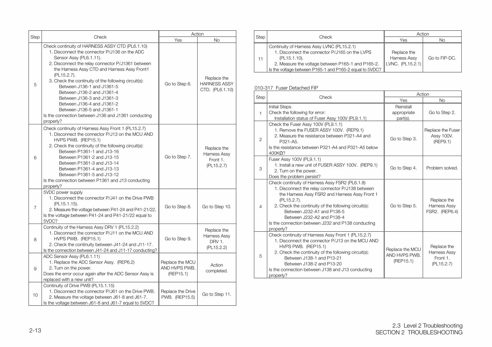
2.3 Level 2 TroubleshootingSECTION 2 TROUBLESHOOTING2-13
ActionStep Check
Yes No
5
Check continuity of HARNESS ASSY CTD (PL6.1.10)1. Disconnect the connector P/J136 on the ADC
Sensor Assy (PL6.1.11).2. Disconnect the relay connector P/J1361 between
the Harness Assy CTD and Harness Assy Front1 (PL15.2.7).
3. Check the continuity of the following circuit(s):Between J136-1 and J1361-5Between J136-2 and J1361-4Between J136-3 and J1361-3Between J136-4 and J1361-2Between J136-5 and J1361-1
Is the connection between J136 and J1361 conductingproperly?
Go to Step 6.Replace the
HARNESS ASSYCTD. (PL6.1.10)
6
Check continuity of Harness Assy Front 1 (PL15.2.7)1. Disconnect the connector P/J13 on the MCU AND
HVPS PWB. (REP15.1)2. Check the continuity of the following circuit(s):
Between P1361-1 and J13-16Between P1361-2 and J13-15Between P1361-3 and J13-14Between P1361-4 and J13-13Between P1361-5 and J13-12
Is the connection between P1361 and J13 conductingproperly?
Go to Step 7.
Replace theHarness Assy
Front 1.(PL15.2.7)
7
5VDC power supply1. Disconnect the connector P/J41 on the Drive PWB
(PL15.1.15).2. Measure the voltage between P41-24 and P41-21/22.
Is the voltage between P41-24 and P41-21/22 equal to5VDC?
Go to Step 8. Go to Step 10.
8
Continuity of the Harness Assy DRV 1 (PL15.2.2)1. Disconnect the connector P/J11 on the MCU AND
HVPS PWB. (REP15.1)2. Check the continuity between J41-24 and J11-17.
Is the connection between J41-24 and J11-17 conducting?
Go to Step 9.
Replace theHarness Assy
DRV 1.(PL15.2.2)
9
ADC Sensor Assy (PL6.1.11)1. Replace the ADC Sensor Assy. (REP6.2)2. Turn on the power.
Does the error occur again after the ADC Sensor Assy isreplaced with a new unit?
Replace the MCUAND HVPS PWB.
(REP15.1)
Actioncompleted.
10
Continuity of Drive PWB (PL15.1.15)1. Disconnect the connector P/J61 on the Drive PWB.2. Measure the voltage between J61-8 and J61-7.
Is the voltage between J61-8 and J61-7 equal to 5VDC?
Replace the DrivePWB. (REP15.5)
Go to Step 11.
ActionStep Check
Yes No
11
Continuity of Harness Assy LVNC (PL15.2.1)1. Disconnect the connector P/J165 on the LVPS
(PL15.1.10).2. Measure the voltage between P165-1 and P165-2.
Is the voltage between P165-1 and P165-2 equal to 5VDC?
Replace theHarness Assy
LVNC. (PL15.2.1)Go to FIP-DC.
010-317 Fuser Detached FIPAction
Step CheckYes No
1Initial StepsCheck the following for error:
Installation status of Fuser Assy 100V (PL9.1.1)
Reinstallappropriate
part(s).Go to Step 2.
2
Check the Fuser Assy 100V (PL9.1.1)1. Remove the FUSER ASSY 100V. (REP9.1)2. Measure the resistance between P321-A4 and
P321-A5.Is the resistance between P321-A4 and P321-A5 below400KΩ?
Go to Step 3.
Replace the FuserAssy 100V.(REP9.1)
3
Fuser Assy 100V (PL9.1.1)1. Install a new unit of FUSER ASSY 100V. (REP9.1)2. Turn on the power.
Does the problem persist?
Go to Step 4. Problem solved.
4
Check continuity of Harness Assy FSR2 (PL6.1.8)1. Disconnect the relay connector P/J138 between
the Harness Assy FSR2 and Harness Assy Front 1 (PL15.2.7).
2. Check the continuity of the following circuit(s):Between J232-A1 and P138-5Between J232-A2 and P138-4
Is the connection between J232 and P138 conductingproperly?
Go to Step 5.Replace the
Harness AssyFSR2. (REP6.4)
5
Check continuity of Harness Assy Front 1 (PL15.2.7)1. Disconnect the connector P/J13 on the MCU AND
HVPS PWB. (REP15.1)2. Check the continuity of the following circuit(s):
Between J138-1 and P13-21Between J138-2 and P13-20
Is the connection between J138 and J13 conductingproperly?
Replace the MCUAND HVPS PWB.
(REP15.1)
Replace theHarness Assy
Front 1.(PL15.2.7)
SECTION 2 TROUBLESHOOTING2.3 Level 2 Troubleshooting
2-14
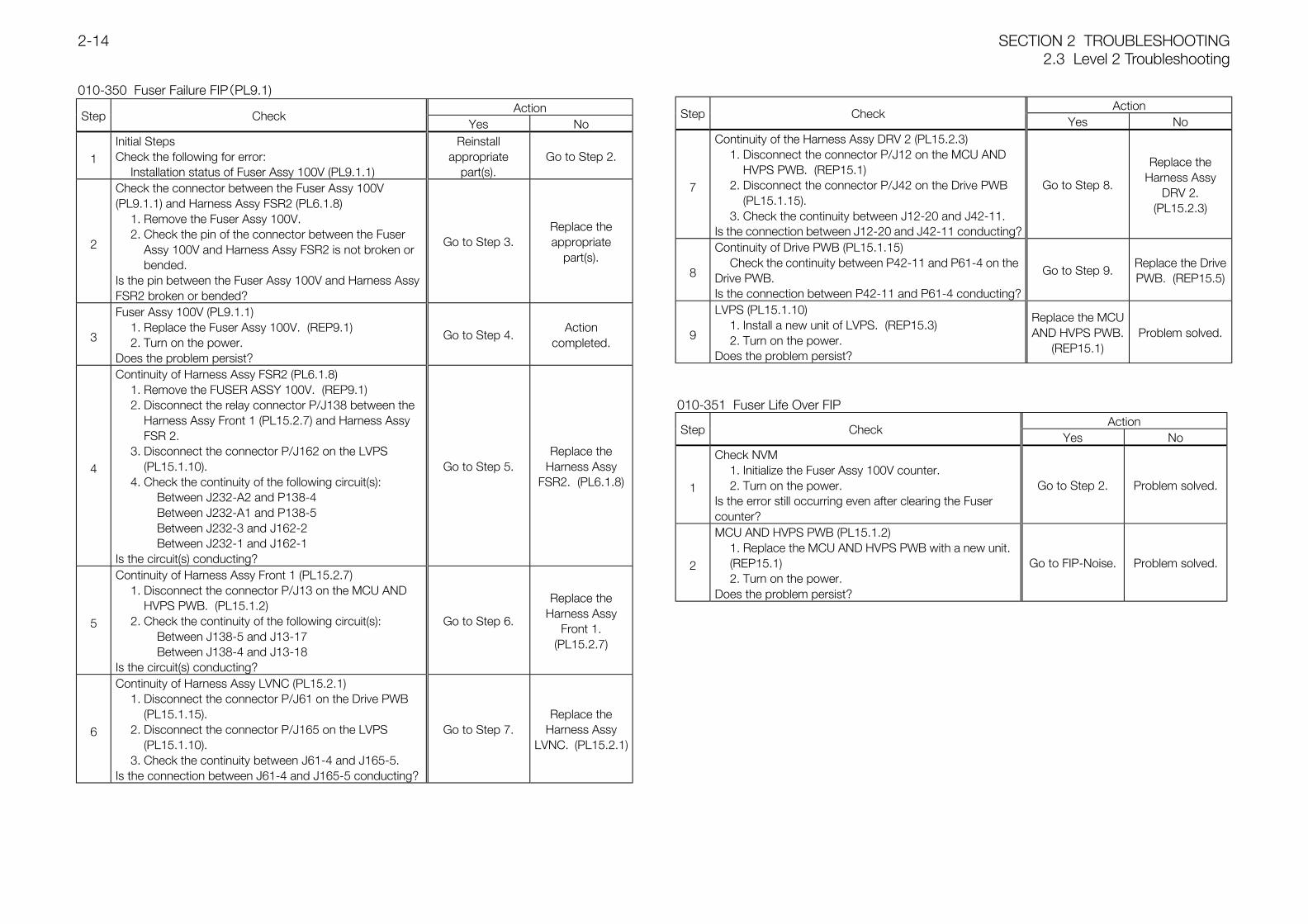
010-350 Fuser Failure FIP(PL9.1)Action
Step CheckYes No
1Initial StepsCheck the following for error:
Installation status of Fuser Assy 100V (PL9.1.1)
Reinstallappropriate
part(s).Go to Step 2.
2
Check the connector between the Fuser Assy 100V(PL9.1.1) and Harness Assy FSR2 (PL6.1.8)
1. Remove the Fuser Assy 100V.2. Check the pin of the connector between the Fuser
Assy 100V and Harness Assy FSR2 is not broken or bended.
Is the pin between the Fuser Assy 100V and Harness AssyFSR2 broken or bended?
Go to Step 3.Replace theappropriate
part(s).
3
Fuser Assy 100V (PL9.1.1)1. Replace the Fuser Assy 100V. (REP9.1)2. Turn on the power.
Does the problem persist?
Go to Step 4.Action
completed.
4
Continuity of Harness Assy FSR2 (PL6.1.8)1. Remove the FUSER ASSY 100V. (REP9.1)2. Disconnect the relay connector P/J138 between the
Harness Assy Front 1 (PL15.2.7) and Harness Assy FSR 2.
3. Disconnect the connector P/J162 on the LVPS (PL15.1.10).
4. Check the continuity of the following circuit(s):Between J232-A2 and P138-4Between J232-A1 and P138-5Between J232-3 and J162-2Between J232-1 and J162-1
Is the circuit(s) conducting?
Go to Step 5.Replace the
Harness AssyFSR2. (PL6.1.8)
5
Continuity of Harness Assy Front 1 (PL15.2.7)1. Disconnect the connector P/J13 on the MCU AND
HVPS PWB. (PL15.1.2)2. Check the continuity of the following circuit(s):
Between J138-5 and J13-17Between J138-4 and J13-18
Is the circuit(s) conducting?
Go to Step 6.
Replace theHarness Assy
Front 1.(PL15.2.7)
6
Continuity of Harness Assy LVNC (PL15.2.1)1. Disconnect the connector P/J61 on the Drive PWB
(PL15.1.15).2. Disconnect the connector P/J165 on the LVPS
(PL15.1.10).3. Check the continuity between J61-4 and J165-5.
Is the connection between J61-4 and J165-5 conducting?
Go to Step 7.Replace the
Harness AssyLVNC. (PL15.2.1)
ActionStep Check
Yes No
7
Continuity of the Harness Assy DRV 2 (PL15.2.3)1. Disconnect the connector P/J12 on the MCU AND
HVPS PWB. (REP15.1)2. Disconnect the connector P/J42 on the Drive PWB
(PL15.1.15).3. Check the continuity between J12-20 and J42-11.
Is the connection between J12-20 and J42-11 conducting?
Go to Step 8.
Replace theHarness Assy
DRV 2.(PL15.2.3)
8
Continuity of Drive PWB (PL15.1.15)Check the continuity between P42-11 and P61-4 on the
Drive PWB.Is the connection between P42-11 and P61-4 conducting?
Go to Step 9.Replace the DrivePWB. (REP15.5)
9
LVPS (PL15.1.10)1. Install a new unit of LVPS. (REP15.3)2. Turn on the power.
Does the problem persist?
Replace the MCUAND HVPS PWB.
(REP15.1)Problem solved.
010-351 Fuser Life Over FIPAction
Step CheckYes No
1
Check NVM1. Initialize the Fuser Assy 100V counter.2. Turn on the power.
Is the error still occurring even after clearing the Fusercounter?
Go to Step 2. Problem solved.
2
MCU AND HVPS PWB (PL15.1.2)1. Replace the MCU AND HVPS PWB with a new unit. (REP15.1)2. Turn on the power.
Does the problem persist?
Go to FIP-Noise. Problem solved.
2.3 Level 2 TroubleshootingSECTION 2 TROUBLESHOOTING2-15
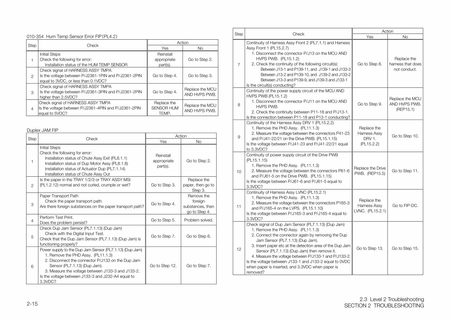
010-354 Hum Temp Sensor Error FIP(PL4.2)Action
Step CheckYes No
1Initial StepsCheck the following for error:
Installation status of the HUM TEMP SENSOR
Reinstallappropriate
part(s).Go to Step 2.
2Check signal of HARNESS ASSY TMPAIs the voltage between P/J2361-1PIN and P/J2361-2PINequal to 3VDC, or less than 0.1VDC?
Go to Step 4. Go to Step 3.
3Check signal of HARNESS ASSY TMPAIs the voltage between P/J2361-3PIN and P/J2361-2PINhigher than 2.5VDC?
Go to Step 4.Replace the MCUAND HVPS PWB.
4Check signal of HARNESS ASSY TMPAIs the voltage between P/J2361-4PIN and P/J2361-2PINequal to 5VDC?
Replace theSENSOR HUM
TEMP.
Replace the MCUAND HVPS PWB.
Duplex JAM FIPAction
Step CheckYes No
1
Initial StepsCheck the following for error:
Installation status of Chute Assy Exit (PL8.1.1)Installation status of Dup Motor Assy (PL8.1.8)Installation status of Actuator Dup (PL7.1.14)Installation status of Chute Assy Out
Reinstallappropriate
part(s).Go to Step 2.
2Is the paper in the TRAY 1/2/3 or TRAY ASSY MSI(PL1.2.12) normal and not curled, crumple or wet? Go to Step 3.
Replace thepaper, then go to
Step 3.
3
Paper Transport PathCheck the paper transport path.
Are there foreign substances on the paper transport path?Go to Step 4.
Remove theforeign
substances, thengo to Step 4.
4Perform Test Print.Does the problem persist?
Go to Step 5. Problem solved.
5
Check Dup Jam Sensor (PL7.1.13) (Dup Jam)Check with the Digital Input Test.
Check that the Dup Jam Sensor (PL7.1.13) (Dup Jam) isfunctioning properly?
Go to Step 7. Go to Step 6.
6
Power supply to the Dup Jam Sensor (PL7.1.13) (Dup Jam)1. Remove the PHD Assy. (PL11.1.3)2. Disconnect the connector P/J133 on the Dup Jam
Sensor (PL7.1.13) (Dup Jam).3. Measure the voltage between J133-3 and J133-2.
Is the voltage between J133-3 and J232-A4 equal to3.3VDC?
Go to Step 12. Go to Step 7.
ActionStep Check
Yes No
7
Continuity of Harness Assy Front 2 (PL7.1.1) and HarnessAssy Front 1 (PL15.2.7)
1. Disconnect the connector P/J13 on the MCU AND HVPS PWB. (PL15.1.2)
2. Check the continuity of the following circuit(s):Between J13-1 and P139-11, and J139-1 and J133-3Between J13-2 and P139-10, and J139-2 and J133-2Between J13-3 and P139-9, and J139-3 and J133-1
Is the circuit(s) conducting?
Go to Step 8.Replace the
harness that doesnot conduct.
8
Continuity of the power supply circuit of the MCU ANDHVPS PWB (PL15.1.2)
1. Disconnect the connector P/J11 on the MCU AND HVPS PWB.
2. Check the continuity between P11-18 and P/J13-1.Is the connection between P11-18 and P13-1 conducting?
Go to Step 9.Replace the MCUAND HVPS PWB.
(REP15.1)
9
Continuity of the Harness Assy DRV 1 (PL15.2.2)1. Remove the PHD Assy. (PL11.1.3)2. Measure the voltage between the connectors P41-23and P/J41-22/21 on the Drive PWB. (PL15.1.15)
Is the voltage between P/J41-23 and P/J41-22/21 equalto 3.3VDC?
Replace theHarness Assy
DRV 1.(PL15.2.2)
Go to Step 10.
10
Continuity of power supply circuit of the Drive PWB(PL15.1.15)
1. Remove the PHD Assy. (PL11.1.3)2. Measure the voltage between the connectors P61-6 and P/J61-5 on the Drive PWB. (PL15.1.15)
Is the voltage between P/J61-6 and P/J61-5 equal to3.3VDC?
Replace the DrivePWB. (REP15.5)
Go to Step 11.
11
Continuity of Harness Assy LVNC (PL15.2.1)1. Remove the PHD Assy. (PL11.1.3)2. Measure the voltage between the connectors P165-3 and P/J165-4 on the LVPS. (PL15.1.10)
Is the voltage between P/J165-3 and P/J165-4 equal to3.3VDC?
Replace theHarness Assy
LVNC. (PL15.2.1)Go to FIP-DC.
12
Check signal of Dup Jam Sensor (PL7.1.13) (Dup Jam)1. Remove the PHD Assy. (PL11.1.3)2. Connect the connector again by removing the Dup
Jam Sensor (PL7.1.13) (Dup Jam).3. Insert paper etc at the detection area of the Dup Jam
Sensor (PL7.1.13) (Dup Jam) then remove it.4. Measure the voltage between P/J133-1 and P/J133-2.
Is the voltage between J133-1 and J133-2 equal to 0VDCwhen paper is inserted, and 3.3VDC when paper isremoved?
Go to Step 13. Go to Step 15.
SECTION 2 TROUBLESHOOTING2.3 Level 2 Troubleshooting
2-16
ActionStep Check
Yes No
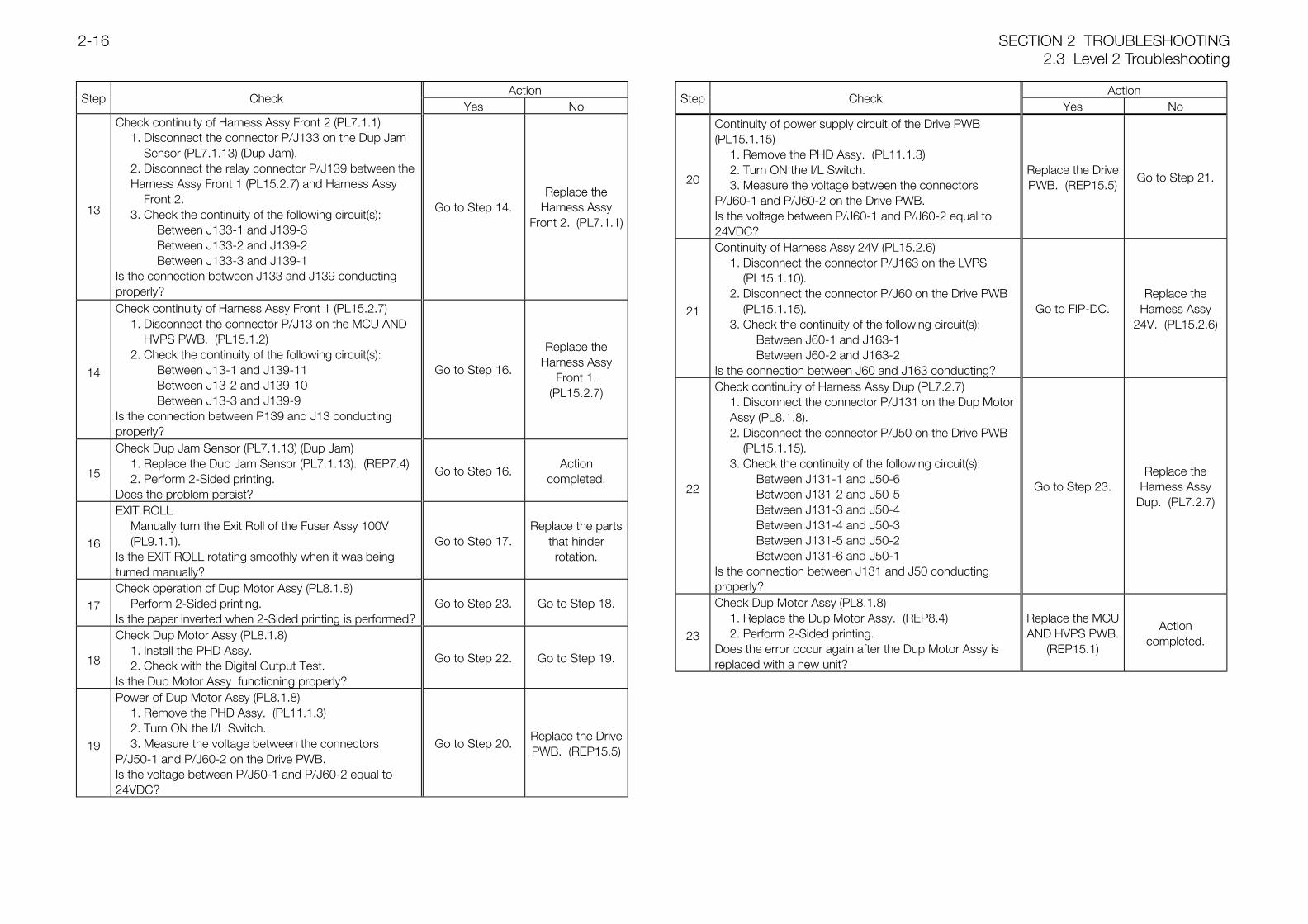
13
Check continuity of Harness Assy Front 2 (PL7.1.1)1. Disconnect the connector P/J133 on the Dup Jam
Sensor (PL7.1.13) (Dup Jam).2. Disconnect the relay connector P/J139 between the Harness Assy Front 1 (PL15.2.7) and Harness Assy
Front 2.3. Check the continuity of the following circuit(s):
Between J133-1 and J139-3Between J133-2 and J139-2Between J133-3 and J139-1
Is the connection between J133 and J139 conductingproperly?
Go to Step 14.Replace the
Harness AssyFront 2. (PL7.1.1)
14
Check continuity of Harness Assy Front 1 (PL15.2.7)1. Disconnect the connector P/J13 on the MCU AND
HVPS PWB. (PL15.1.2)2. Check the continuity of the following circuit(s):
Between J13-1 and J139-11Between J13-2 and J139-10Between J13-3 and J139-9
Is the connection between P139 and J13 conductingproperly?
Go to Step 16.
Replace theHarness Assy
Front 1.(PL15.2.7)
15
Check Dup Jam Sensor (PL7.1.13) (Dup Jam)1. Replace the Dup Jam Sensor (PL7.1.13). (REP7.4)2. Perform 2-Sided printing.
Does the problem persist?
Go to Step 16.Action
completed.
16
EXIT ROLLManually turn the Exit Roll of the Fuser Assy 100V (PL9.1.1).
Is the EXIT ROLL rotating smoothly when it was beingturned manually?
Go to Step 17.Replace the parts
that hinderrotation.
17Check operation of Dup Motor Assy (PL8.1.8)
Perform 2-Sided printing.Is the paper inverted when 2-Sided printing is performed?
Go to Step 23. Go to Step 18.
18
Check Dup Motor Assy (PL8.1.8)1. Install the PHD Assy.2. Check with the Digital Output Test.
Is the Dup Motor Assy functioning properly?
Go to Step 22. Go to Step 19.
19
Power of Dup Motor Assy (PL8.1.8)1. Remove the PHD Assy. (PL11.1.3)2. Turn ON the I/L Switch.3. Measure the voltage between the connectors
P/J50-1 and P/J60-2 on the Drive PWB.Is the voltage between P/J50-1 and P/J60-2 equal to24VDC?
Go to Step 20.Replace the DrivePWB. (REP15.5)
ActionStep Check
Yes No
20
Continuity of power supply circuit of the Drive PWB(PL15.1.15)
1. Remove the PHD Assy. (PL11.1.3)2. Turn ON the I/L Switch.3. Measure the voltage between the connectors
P/J60-1 and P/J60-2 on the Drive PWB.Is the voltage between P/J60-1 and P/J60-2 equal to24VDC?
Replace the DrivePWB. (REP15.5)
Go to Step 21.
21
Continuity of Harness Assy 24V (PL15.2.6)1. Disconnect the connector P/J163 on the LVPS
(PL15.1.10).2. Disconnect the connector P/J60 on the Drive PWB
(PL15.1.15).3. Check the continuity of the following circuit(s):
Between J60-1 and J163-1Between J60-2 and J163-2
Is the connection between J60 and J163 conducting?
Go to FIP-DC.Replace the
Harness Assy24V. (PL15.2.6)
22
Check continuity of Harness Assy Dup (PL7.2.7)1. Disconnect the connector P/J131 on the Dup Motor Assy (PL8.1.8).2. Disconnect the connector P/J50 on the Drive PWB
(PL15.1.15).3. Check the continuity of the following circuit(s):
Between J131-1 and J50-6Between J131-2 and J50-5Between J131-3 and J50-4Between J131-4 and J50-3Between J131-5 and J50-2Between J131-6 and J50-1
Is the connection between J131 and J50 conductingproperly?
Go to Step 23.Replace the
Harness AssyDup. (PL7.2.7)
23
Check Dup Motor Assy (PL8.1.8)1. Replace the Dup Motor Assy. (REP8.4)2. Perform 2-Sided printing.
Does the error occur again after the Dup Motor Assy isreplaced with a new unit?
Replace the MCUAND HVPS PWB.
(REP15.1)
Actioncompleted.
2.3 Level 2 TroubleshootingSECTION 2 TROUBLESHOOTING2-17
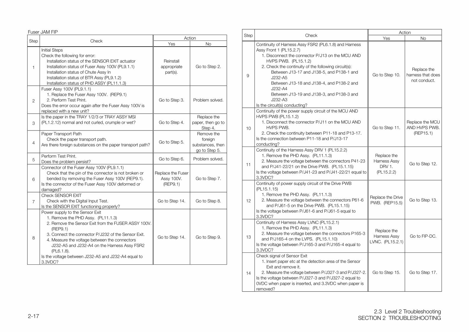
Fuser JAM FIPAction
Step CheckYes No
1
Initial StepsCheck the following for error:
Installation status of the SENSOR EXIT actuatorInstallation status of Fuser Assy 100V (PL9.1.1)Installation status of Chute Assy InInstallation status of BTR Assy (PL9.1.2)Installation status of PHD ASSY (PL11.1.3)
Reinstallappropriate
part(s).Go to Step 2.
2
Fuser Assy 100V (PL9.1.1)1. Replace the Fuser Assy 100V. (REP9.1)2. Perform Test Print.
Does the error occur again after the Fuser Assy 100V isreplaced with a new unit?
Go to Step 3. Problem solved.
3Is the paper in the TRAY 1/2/3 or TRAY ASSY MSI(PL1.2.12) normal and not curled, crumple or wet? Go to Step 4.
Replace thepaper, then go to
Step 4.
4
Paper Transport PathCheck the paper transport path.
Are there foreign substances on the paper transport path?Go to Step 5.
Remove theforeign
substances, thengo to Step 5.
5Perform Test Print.Does the problem persist?
Go to Step 6. Problem solved.
6
Connector of the Fuser Assy 100V (PL9.1.1)Check that the pin of the connector is not broken or bended by removing the Fuser Assy 100V (REP9.1).
Is the connector of the Fuser Assy 100V deformed ordamaged?
Replace the FuserAssy 100V.(REP9.1)
Go to Step 7.
7Check SENSOR EXIT
Check with the Digital Input Test.Is the SENSOR EXIT functioning properly?
Go to Step 14. Go to Step 8.
8
Power supply to the Sensor Exit1. Remove the PHD Assy. (PL11.1.3)2. Remove the Sensor Exit from the FUSER ASSY 100V.
(REP9.1)3. Connect the connector P/J232 of the Sensor Exit.4. Measure the voltage between the connectors
J232-A5 and J232-A4 on the Harness Assy FSR2 (PL6.1.8).
Is the voltage between J232-A5 and J232-A4 equal to3.3VDC?
Go to Step 14. Go to Step 9.
ActionStep Check
Yes No
9
Continuity of Harness Assy FSR2 (PL6.1.8) and HarnessAssy Front 1 (PL15.2.7)
1. Disconnect the connector P/J13 on the MCU AND HVPS PWB. (PL15.1.2)
2. Check the continuity of the following circuit(s):Between J13-17 and J138-5, and P138-1 and J232-A5Between J13-18 and J138-4, and P138-2 and J232-A4Between J13-19 and J138-3, and P138-3 and J232-A3
Is the circuit(s) conducting?
Go to Step 10.Replace the
harness that doesnot conduct.
10
Continuity of the power supply circuit of the MCU ANDHVPS PWB (PL15.1.2)
1. Disconnect the connector P/J11 on the MCU AND HVPS PWB.
2. Check the continuity between P11-18 and P13-17.Is the connection between P11-18 and P/J13-17conducting?
Go to Step 11.Replace the MCUAND HVPS PWB.
(REP15.1)
11
Continuity of the Harness Assy DRV 1 (PL15.2.2)1. Remove the PHD Assy. (PL11.1.3)2. Measure the voltage between the connectors P41-23 and P/J41-22/21 on the Drive PWB. (PL15.1.15)
Is the voltage between P/J41-23 and P/J41-22/21 equal to3.3VDC?
Replace theHarness Assy
DRV 1.(PL15.2.2)
Go to Step 12.
12
Continuity of power supply circuit of the Drive PWB(PL15.1.15)
1. Remove the PHD Assy. (PL11.1.3)2. Measure the voltage between the connectors P61-6
and P/J61-5 on the Drive PWB. (PL15.1.15)Is the voltage between P/J61-6 and P/J61-5 equal to3.3VDC?
Replace the DrivePWB. (REP15.5)
Go to Step 13.
13
Continuity of Harness Assy LVNC (PL15.2.1)1. Remove the PHD Assy. (PL11.1.3)2. Measure the voltage between the connectors P165-3 and P/J165-4 on the LVPS. (PL15.1.10)
Is the voltage between P/J165-3 and P/J165-4 equal to3.3VDC?
Replace theHarness Assy
LVNC. (PL15.2.1)Go to FIP-DC.
14
Check signal of Sensor Exit1. Insert paper etc at the detection area of the Sensor
Exit and remove it.2. Measure the voltage between P/J327-3 and P/J327-2.
Is the voltage between P/J327-3 and P/J327-2 equal to0VDC when paper is inserted, and 3.3VDC when paper isremoved?
Go to Step 15. Go to Step 17.
SECTION 2 TROUBLESHOOTING2.3 Level 2 Troubleshooting
2-18
ActionStep Check
Yes No
15
Check continuity of Harness Assy FSR2 (PL6.1.8)1. Remove the FUSER ASSY 100V. (REP9.1)2. Disconnect the relay connector P/J138 between the
Harness Assy FSR2 and Harness Assy Front 1 (PL15.2.7).
3. Check the continuity of the following circuit(s):Between J232-A4 and P138-2Between J232-A3 and P138-3
Is the connection between J232 and J138 conductingproperly?
Go to Step 16.Replace the
Harness AssyFSR2. (PL6.1.8)
16
Check continuity of Harness Assy Front 1 (PL15.2.7)1. Disconnect the connector P/J13 on the MCU AND
HVPS PWB. (PL15.1.2)2. Check the continuity of the following circuit(s):
Between J13-19 and J138-3Between J13-18 and J138-4
Is the connection between J13 and J138 conductingproperly?
Go to Step 17.
Replace theHarness Assy
Front 1.(PL15.2.7)
17
Check operation of Fuser Drive Assy (PL6.2.1)1. Perform Test Print.2. Check that the lead edge of the paper is inserted
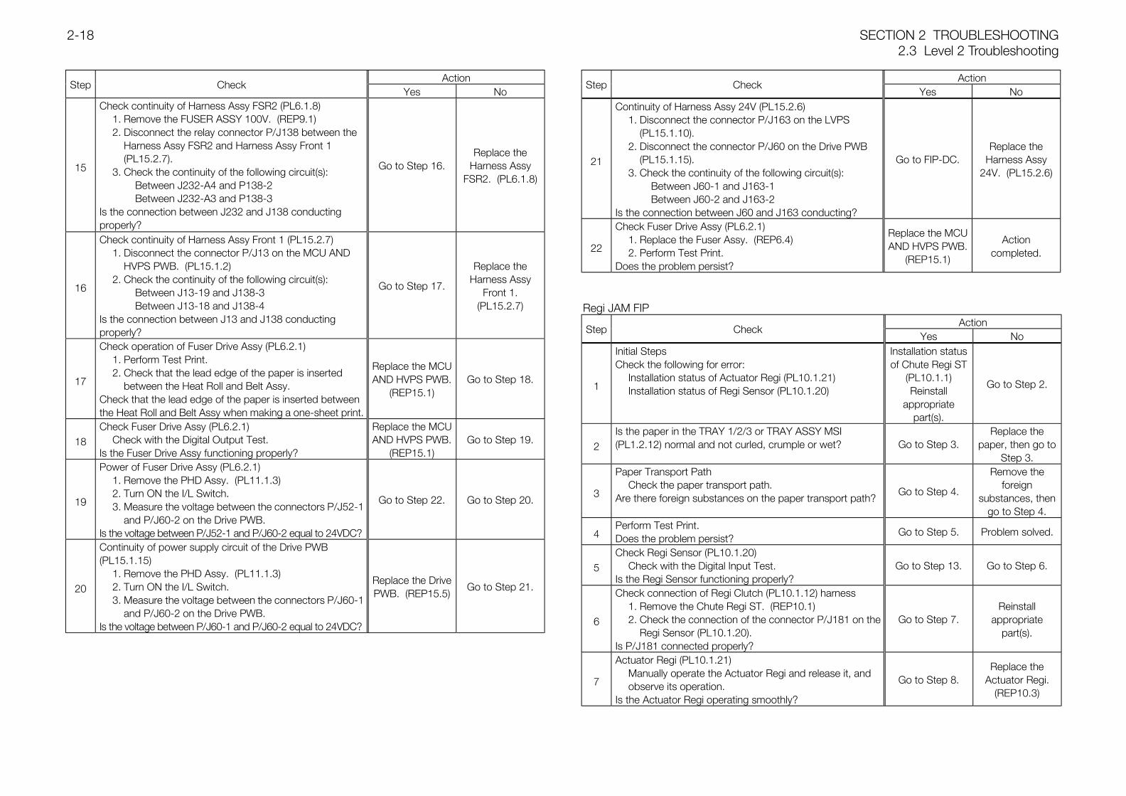
between the Heat Roll and Belt Assy.Check that the lead edge of the paper is inserted betweenthe Heat Roll and Belt Assy when making a one-sheet print.
Replace the MCUAND HVPS PWB.
(REP15.1)Go to Step 18.
18Check Fuser Drive Assy (PL6.2.1)
Check with the Digital Output Test.Is the Fuser Drive Assy functioning properly?
Replace the MCUAND HVPS PWB.
(REP15.1)Go to Step 19.
19
Power of Fuser Drive Assy (PL6.2.1)1. Remove the PHD Assy. (PL11.1.3)2. Turn ON the I/L Switch.3. Measure the voltage between the connectors P/J52-1
and P/J60-2 on the Drive PWB.Is the voltage between P/J52-1 and P/J60-2 equal to 24VDC?
Go to Step 22. Go to Step 20.
20
Continuity of power supply circuit of the Drive PWB(PL15.1.15)
1. Remove the PHD Assy. (PL11.1.3)2. Turn ON the I/L Switch.3. Measure the voltage between the connectors P/J60-1
and P/J60-2 on the Drive PWB.Is the voltage between P/J60-1 and P/J60-2 equal to 24VDC?
Replace the DrivePWB. (REP15.5)
Go to Step 21.
ActionStep Check
Yes No
21
Continuity of Harness Assy 24V (PL15.2.6)1. Disconnect the connector P/J163 on the LVPS
(PL15.1.10).2. Disconnect the connector P/J60 on the Drive PWB
(PL15.1.15).3. Check the continuity of the following circuit(s):
Between J60-1 and J163-1Between J60-2 and J163-2
Is the connection between J60 and J163 conducting?
Go to FIP-DC.Replace the
Harness Assy24V. (PL15.2.6)
22
Check Fuser Drive Assy (PL6.2.1)1. Replace the Fuser Assy. (REP6.4)2. Perform Test Print.
Does the problem persist?
Replace the MCUAND HVPS PWB.
(REP15.1)
Actioncompleted.
Regi JAM FIPAction
Step CheckYes No
1
Initial StepsCheck the following for error:
Installation status of Actuator Regi (PL10.1.21)Installation status of Regi Sensor (PL10.1.20)
Installation statusof Chute Regi ST
(PL10.1.1)Reinstall
appropriatepart(s).
Go to Step 2.
2Is the paper in the TRAY 1/2/3 or TRAY ASSY MSI(PL1.2.12) normal and not curled, crumple or wet? Go to Step 3.
Replace thepaper, then go to
Step 3.
3
Paper Transport PathCheck the paper transport path.
Are there foreign substances on the paper transport path?Go to Step 4.
Remove theforeign
substances, thengo to Step 4.
4Perform Test Print.Does the problem persist?
Go to Step 5. Problem solved.
5Check Regi Sensor (PL10.1.20)
Check with the Digital Input Test.Is the Regi Sensor functioning properly?
Go to Step 13. Go to Step 6.
6
Check connection of Regi Clutch (PL10.1.12) harness1. Remove the Chute Regi ST. (REP10.1)2. Check the connection of the connector P/J181 on the
Regi Sensor (PL10.1.20).Is P/J181 connected properly?
Go to Step 7.Reinstall
appropriatepart(s).
7
Actuator Regi (PL10.1.21)Manually operate the Actuator Regi and release it, and observe its operation.
Is the Actuator Regi operating smoothly?
Go to Step 8.Replace the
Actuator Regi.(REP10.3)
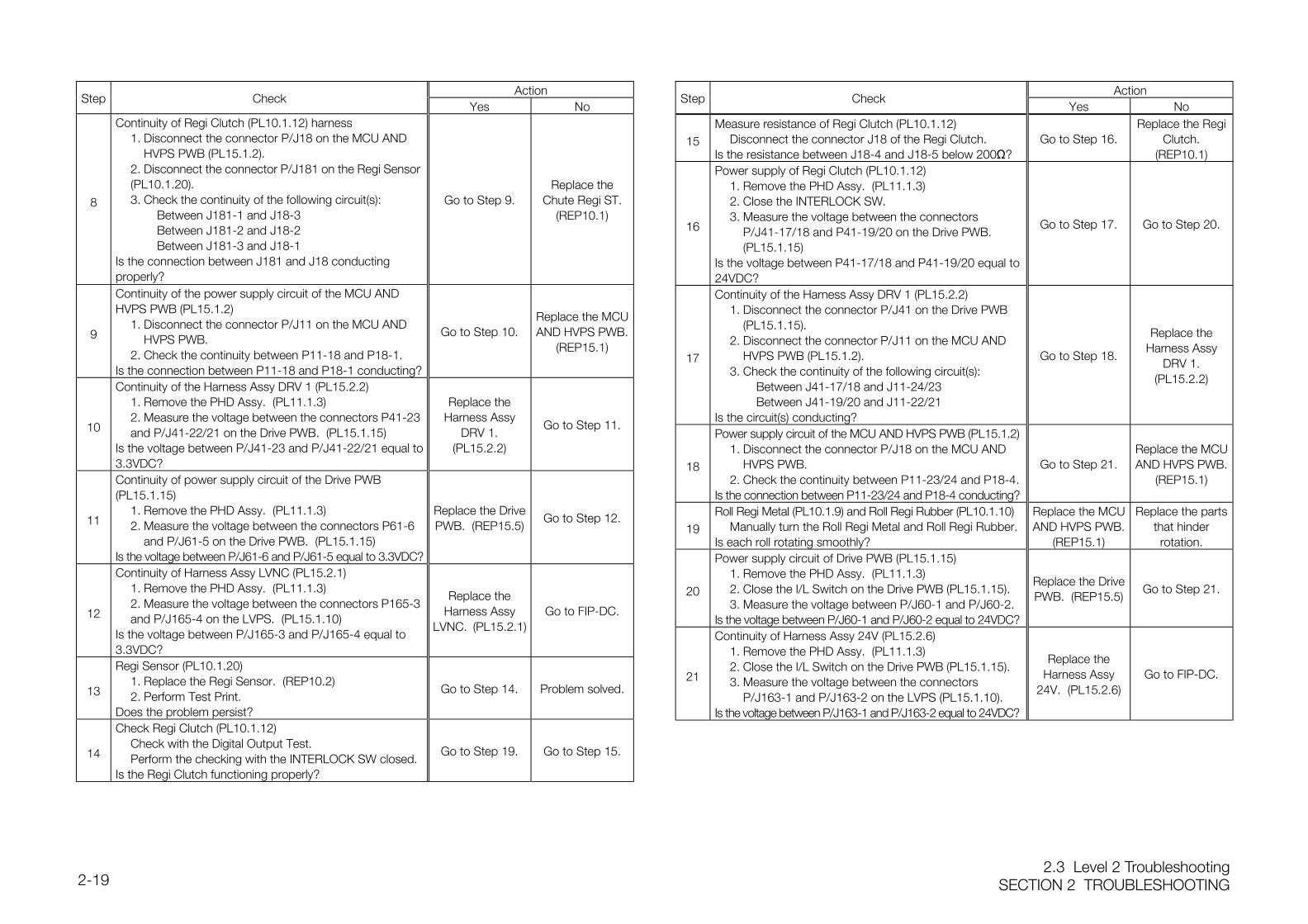
2.3 Level 2 TroubleshootingSECTION 2 TROUBLESHOOTING2-19
ActionStep Check
Yes No
8
Continuity of Regi Clutch (PL10.1.12) harness1. Disconnect the connector P/J18 on the MCU AND
HVPS PWB (PL15.1.2).2. Disconnect the connector P/J181 on the Regi Sensor (PL10.1.20).3. Check the continuity of the following circuit(s):
Between J181-1 and J18-3Between J181-2 and J18-2Between J181-3 and J18-1
Is the connection between J181 and J18 conductingproperly?
Go to Step 9.Replace the
Chute Regi ST.(REP10.1)
9
Continuity of the power supply circuit of the MCU ANDHVPS PWB (PL15.1.2)
1. Disconnect the connector P/J11 on the MCU AND HVPS PWB.
2. Check the continuity between P11-18 and P18-1.Is the connection between P11-18 and P18-1 conducting?
Go to Step 10.Replace the MCUAND HVPS PWB.
(REP15.1)
10
Continuity of the Harness Assy DRV 1 (PL15.2.2)1. Remove the PHD Assy. (PL11.1.3)2. Measure the voltage between the connectors P41-23 and P/J41-22/21 on the Drive PWB. (PL15.1.15)
Is the voltage between P/J41-23 and P/J41-22/21 equal to3.3VDC?
Replace theHarness Assy
DRV 1.(PL15.2.2)
Go to Step 11.
11
Continuity of power supply circuit of the Drive PWB(PL15.1.15)
1. Remove the PHD Assy. (PL11.1.3)2. Measure the voltage between the connectors P61-6
and P/J61-5 on the Drive PWB. (PL15.1.15)Is the voltage between P/J61-6 and P/J61-5 equal to 3.3VDC?
Replace the DrivePWB. (REP15.5)
Go to Step 12.
12
Continuity of Harness Assy LVNC (PL15.2.1)1. Remove the PHD Assy. (PL11.1.3)2. Measure the voltage between the connectors P165-3 and P/J165-4 on the LVPS. (PL15.1.10)
Is the voltage between P/J165-3 and P/J165-4 equal to3.3VDC?
Replace theHarness Assy
LVNC. (PL15.2.1)Go to FIP-DC.
13
Regi Sensor (PL10.1.20)1. Replace the Regi Sensor. (REP10.2)2. Perform Test Print.
Does the problem persist?
Go to Step 14. Problem solved.
14
Check Regi Clutch (PL10.1.12)Check with the Digital Output Test.Perform the checking with the INTERLOCK SW closed.
Is the Regi Clutch functioning properly?
Go to Step 19. Go to Step 15.
ActionStep Check
Yes No
15Measure resistance of Regi Clutch (PL10.1.12)
Disconnect the connector J18 of the Regi Clutch.Is the resistance between J18-4 and J18-5 below 200Ω?
Go to Step 16.Replace the Regi
Clutch.(REP10.1)
16
Power supply of Regi Clutch (PL10.1.12)1. Remove the PHD Assy. (PL11.1.3)2. Close the INTERLOCK SW.3. Measure the voltage between the connectors
P/J41-17/18 and P41-19/20 on the Drive PWB. (PL15.1.15)
Is the voltage between P41-17/18 and P41-19/20 equal to24VDC?
Go to Step 17. Go to Step 20.
17
Continuity of the Harness Assy DRV 1 (PL15.2.2)1. Disconnect the connector P/J41 on the Drive PWB
(PL15.1.15).2. Disconnect the connector P/J11 on the MCU AND
HVPS PWB (PL15.1.2).3. Check the continuity of the following circuit(s):
Between J41-17/18 and J11-24/23Between J41-19/20 and J11-22/21
Is the circuit(s) conducting?
Go to Step 18.
Replace theHarness Assy
DRV 1.(PL15.2.2)
18
Power supply circuit of the MCU AND HVPS PWB (PL15.1.2)1. Disconnect the connector P/J18 on the MCU AND
HVPS PWB.2. Check the continuity between P11-23/24 and P18-4.
Is the connection between P11-23/24 and P18-4 conducting?
Go to Step 21.Replace the MCUAND HVPS PWB.
(REP15.1)
19Roll Regi Metal (PL10.1.9) and Roll Regi Rubber (PL10.1.10)
Manually turn the Roll Regi Metal and Roll Regi Rubber.Is each roll rotating smoothly?
Replace the MCUAND HVPS PWB.
(REP15.1)
Replace the partsthat hinderrotation.
20
Power supply circuit of Drive PWB (PL15.1.15)1. Remove the PHD Assy. (PL11.1.3)2. Close the I/L Switch on the Drive PWB (PL15.1.15).3. Measure the voltage between P/J60-1 and P/J60-2.
Is the voltage between P/J60-1 and P/J60-2 equal to 24VDC?
Replace the DrivePWB. (REP15.5)
Go to Step 21.
21
Continuity of Harness Assy 24V (PL15.2.6)1. Remove the PHD Assy. (PL11.1.3)2. Close the I/L Switch on the Drive PWB (PL15.1.15).3. Measure the voltage between the connectors
P/J163-1 and P/J163-2 on the LVPS (PL15.1.10).Is the voltage between P/J163-1 and P/J163-2 equal to 24VDC?
Replace theHarness Assy
24V. (PL15.2.6)Go to FIP-DC.
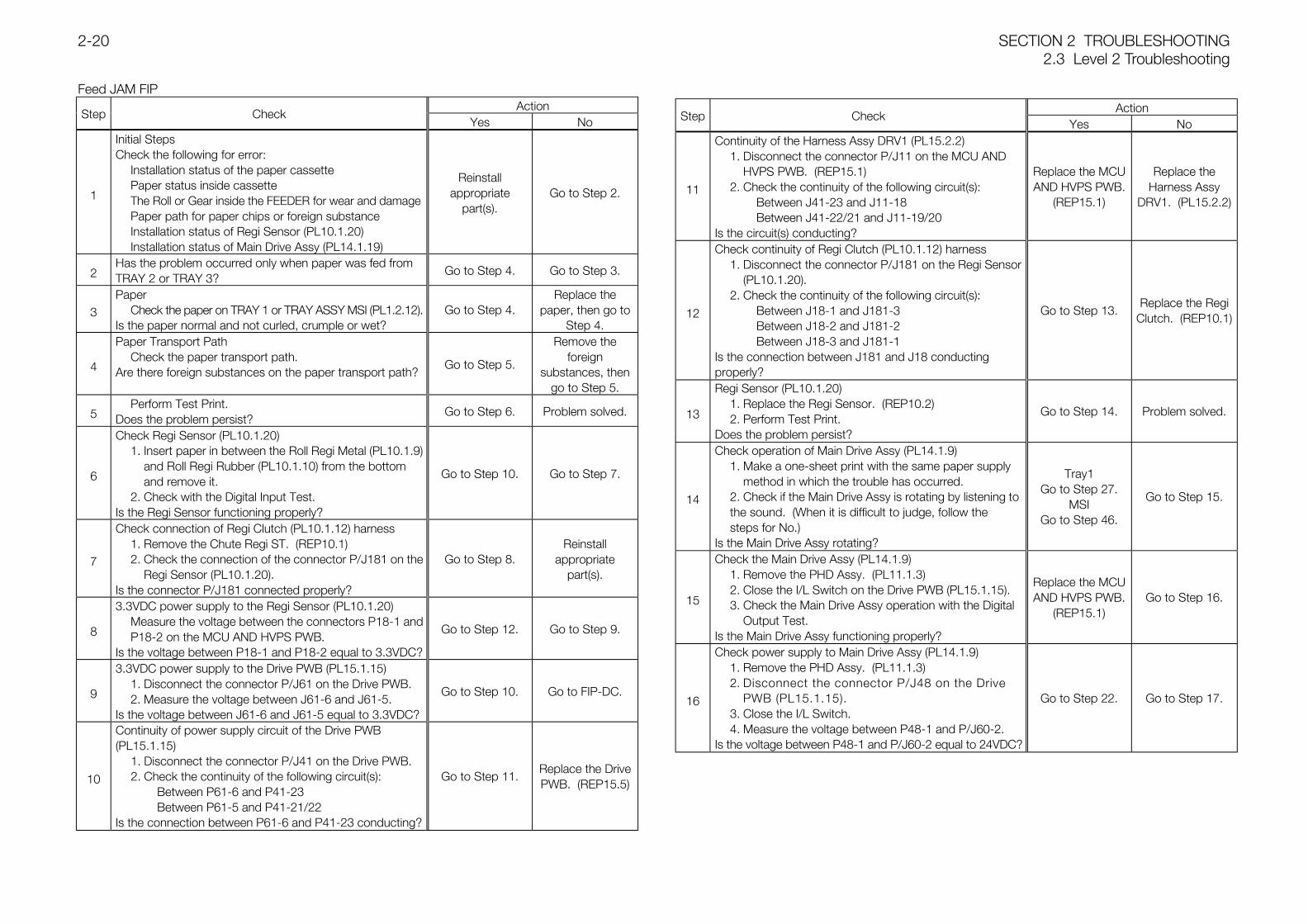
SECTION 2 TROUBLESHOOTING2.3 Level 2 Troubleshooting
2-20
Feed JAM FIPAction
Step CheckYes No
1
Initial StepsCheck the following for error:
Installation status of the paper cassettePaper status inside cassetteThe Roll or Gear inside the FEEDER for wear and damagePaper path for paper chips or foreign substanceInstallation status of Regi Sensor (PL10.1.20)Installation status of Main Drive Assy (PL14.1.19)
Reinstallappropriate
part(s).Go to Step 2.
2Has the problem occurred only when paper was fed fromTRAY 2 or TRAY 3?
Go to Step 4. Go to Step 3.
3Paper
Check the paper on TRAY 1 or TRAY ASSY MSI (PL1.2.12).Is the paper normal and not curled, crumple or wet?
Go to Step 4.Replace the
paper, then go toStep 4.
4
Paper Transport PathCheck the paper transport path.
Are there foreign substances on the paper transport path?Go to Step 5.
Remove theforeign
substances, thengo to Step 5.
5Perform Test Print.
Does the problem persist?Go to Step 6. Problem solved.
6
Check Regi Sensor (PL10.1.20)1. Insert paper in between the Roll Regi Metal (PL10.1.9)
and Roll Regi Rubber (PL10.1.10) from the bottom and remove it.
2. Check with the Digital Input Test.Is the Regi Sensor functioning properly?
Go to Step 10. Go to Step 7.
7
Check connection of Regi Clutch (PL10.1.12) harness1. Remove the Chute Regi ST. (REP10.1)2. Check the connection of the connector P/J181 on the
Regi Sensor (PL10.1.20).Is the connector P/J181 connected properly?
Go to Step 8.Reinstall
appropriatepart(s).
8
3.3VDC power supply to the Regi Sensor (PL10.1.20)Measure the voltage between the connectors P18-1 andP18-2 on the MCU AND HVPS PWB.
Is the voltage between P18-1 and P18-2 equal to 3.3VDC?
Go to Step 12. Go to Step 9.
9
3.3VDC power supply to the Drive PWB (PL15.1.15)1. Disconnect the connector P/J61 on the Drive PWB.2. Measure the voltage between J61-6 and J61-5.
Is the voltage between J61-6 and J61-5 equal to 3.3VDC?
Go to Step 10. Go to FIP-DC.
10
Continuity of power supply circuit of the Drive PWB(PL15.1.15)
1. Disconnect the connector P/J41 on the Drive PWB.2. Check the continuity of the following circuit(s):
Between P61-6 and P41-23Between P61-5 and P41-21/22
Is the connection between P61-6 and P41-23 conducting?
Go to Step 11.Replace the DrivePWB. (REP15.5)
ActionStep Check
Yes No
11
Continuity of the Harness Assy DRV1 (PL15.2.2)1. Disconnect the connector P/J11 on the MCU AND
HVPS PWB. (REP15.1)2. Check the continuity of the following circuit(s):
Between J41-23 and J11-18Between J41-22/21 and J11-19/20
Is the circuit(s) conducting?
Replace the MCUAND HVPS PWB.
(REP15.1)
Replace theHarness Assy
DRV1. (PL15.2.2)
12
Check continuity of Regi Clutch (PL10.1.12) harness1. Disconnect the connector P/J181 on the Regi Sensor
(PL10.1.20).2. Check the continuity of the following circuit(s):
Between J18-1 and J181-3Between J18-2 and J181-2Between J18-3 and J181-1
Is the connection between J181 and J18 conductingproperly?
Go to Step 13.Replace the Regi
Clutch. (REP10.1)
13
Regi Sensor (PL10.1.20)1. Replace the Regi Sensor. (REP10.2)2. Perform Test Print.
Does the problem persist?
Go to Step 14. Problem solved.
14
Check operation of Main Drive Assy (PL14.1.9)1. Make a one-sheet print with the same paper supply
method in which the trouble has occurred.2. Check if the Main Drive Assy is rotating by listening to the sound. (When it is difficult to judge, follow the steps for No.)
Is the Main Drive Assy rotating?
Tray1Go to Step 27.
MSIGo to Step 46.
Go to Step 15.
15
Check the Main Drive Assy (PL14.1.9)1. Remove the PHD Assy. (PL11.1.3)2. Close the I/L Switch on the Drive PWB (PL15.1.15).3. Check the Main Drive Assy operation with the Digital
Output Test.Is the Main Drive Assy functioning properly?
Replace the MCUAND HVPS PWB.
(REP15.1)Go to Step 16.
16
Check power supply to Main Drive Assy (PL14.1.9)1. Remove the PHD Assy. (PL11.1.3)2. Disconnect the connector P/J48 on the Drive
PWB (PL15.1.15).3. Close the I/L Switch.4. Measure the voltage between P48-1 and P/J60-2.
Is the voltage between P48-1 and P/J60-2 equal to 24VDC?
Go to Step 22. Go to Step 17.
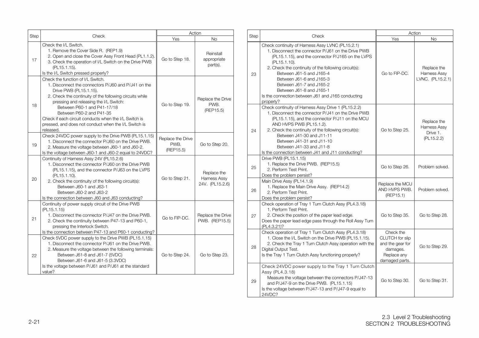
2.3 Level 2 TroubleshootingSECTION 2 TROUBLESHOOTING2-21
ActionStep Check
Yes No
17
Check the I/L Switch.1. Remove the Cover Side R. (REP1.9)2. Open and close the Cover Assy Front Head (PL1.1.2).3. Check the operation of I/L Switch on the Drive PWB
(PL15.1.15).Is the I/L Switch pressed properly?
Go to Step 18.Reinstall
appropriatepart(s).
18
Check the function of I/L Switch.1. Disconnect the connectors P/J60 and P/J41 on the
Drive PWB (PL15.1.15).2. Check the continuity of the following circuits while
pressing and releasing the I/L Switch:Between P60-1 and P41-17/18Between P60-2 and P41-35
Check if each circuit conducts when the I/L Switch ispressed, and does not conduct when the I/L Switch isreleased.
Go to Step 19.Replace the Drive
PWB.(REP15.5)
19
Check 24VDC power supply to the Drive PWB (PL15.1.15)1. Disconnect the connector P/J60 on the Drive PWB.2. Measure the voltage between J60-1 and J60-2.
Is the voltage between J60-1 and J60-2 equal to 24VDC?
Replace the DrivePWB.
(REP15.5)Go to Step 20.
20
Continuity of Harness Assy 24V (PL15.2.6)1. Disconnect the connector P/J60 on the Drive PWB
(PL15.1.15), and the connector P/J63 on the LVPS (PL15.1.10).
2. Check the continuity of the following circuit(s):Between J60-1 and J63-1Between J60-2 and J63-2
Is the connection between J60 and J63 conducting?
Go to Step 21.Replace the
Harness Assy24V. (PL15.2.6)
21
Continuity of power supply circuit of the Drive PWB(PL15.1.15)
1. Disconnect the connector P/J47 on the Drive PWB.2. Check the continuity between P47-13 and P60-1,
pressing the Interlock Switch.Is the connection between P47-13 and P60-1 conducting?
Go to FIP-DC.Replace the DrivePWB. (REP15.5)
22
Check 5VDC power supply to the Drive PWB (PL15.1.15)1. Disconnect the connector P/J61 on the Drive PWB.2. Measure the voltage between the following terminals:
Between J61-8 and J61-7 (5VDC)Between J61-6 and J61-5 (3.3VDC)
Is the voltage between P/J61 and P/J61 at the standardvalue?
Go to Step 24. Go to Step 23.
ActionStep Check
Yes No
23
Check continuity of Harness Assy LVNC (PL15.2.1)1. Disconnect the connector P/J61 on the Drive PWB
(PL15.1.15), and the connector P/J165 on the LVPS (PL15.1.10).
2. Check the continuity of the following circuit(s):Between J61-5 and J165-4Between J61-6 and J165-3Between J61-7 and J165-2Between J61-8 and J165-1
Is the connection between J61 and J165 conductingproperly?
Go to FIP-DC.Replace the
Harness AssyLVNC. (PL15.2.1)
24
Check continuity of Harness Assy Drive 1 (PL15.2.2)1. Disconnect the connector P/J41 on the Drive PWB
(PL15.1.15), and the connector P/J11 on the MCU AND HVPS PWB (PL15.1.2).
2. Check the continuity of the following circuit(s):Between J41-30 and J11-11Between J41-31 and J11-10Between J41-33 and J11-8
Is the connection between J41 and J11 conducting?
Go to Step 25.
Replace theHarness Assy
Drive 1.(PL15.2.2)
25
Drive PWB (PL15.1.15)1. Replace the Drive PWB. (REP15.5)2. Perform Test Print.
Does the problem persist?
Go to Step 26. Problem solved.
26
Main Drive Assy (PL14.1.9)1. Replace the Main Drive Assy. (REP14.2)2. Perform Test Print.
Does the problem persist?
Replace the MCUAND HVPS PWB.
(REP15.1)Problem solved.
27
Check operation of Tray 1 Turn Clutch Assy (PL4.3.18)1. Perform Test Print.2. Check the position of the paper lead edge.
Does the paper lead edge pass through the Roll Assy Turn(PL4.3.21)?
Go to Step 35. Go to Step 28.
28
Check operation of Tray 1 Turn Clutch Assy (PL4.3.18)1. Close the I/L Switch on the Drive PWB (PL15.1.15).2. Check the Tray 1 Turn Clutch Assy operation with the
Digital Output Test.Is the Tray 1 Turn Clutch Assy functioning properly?
Check theCLUTCH for slipand the gear for
damages.Replace any
damaged parts.
Go to Step 29.
29
Check 24VDC power supply to the Tray 1 Turn ClutchAssy (PL4.3.18)
Measure the voltage between the connectors P/J47-13 and P/J47-9 on the Drive PWB. (PL15.1.15)
Is the voltage between P/J47-13 and P/J47-9 equal to24VDC?
Go to Step 30. Go to Step 31.
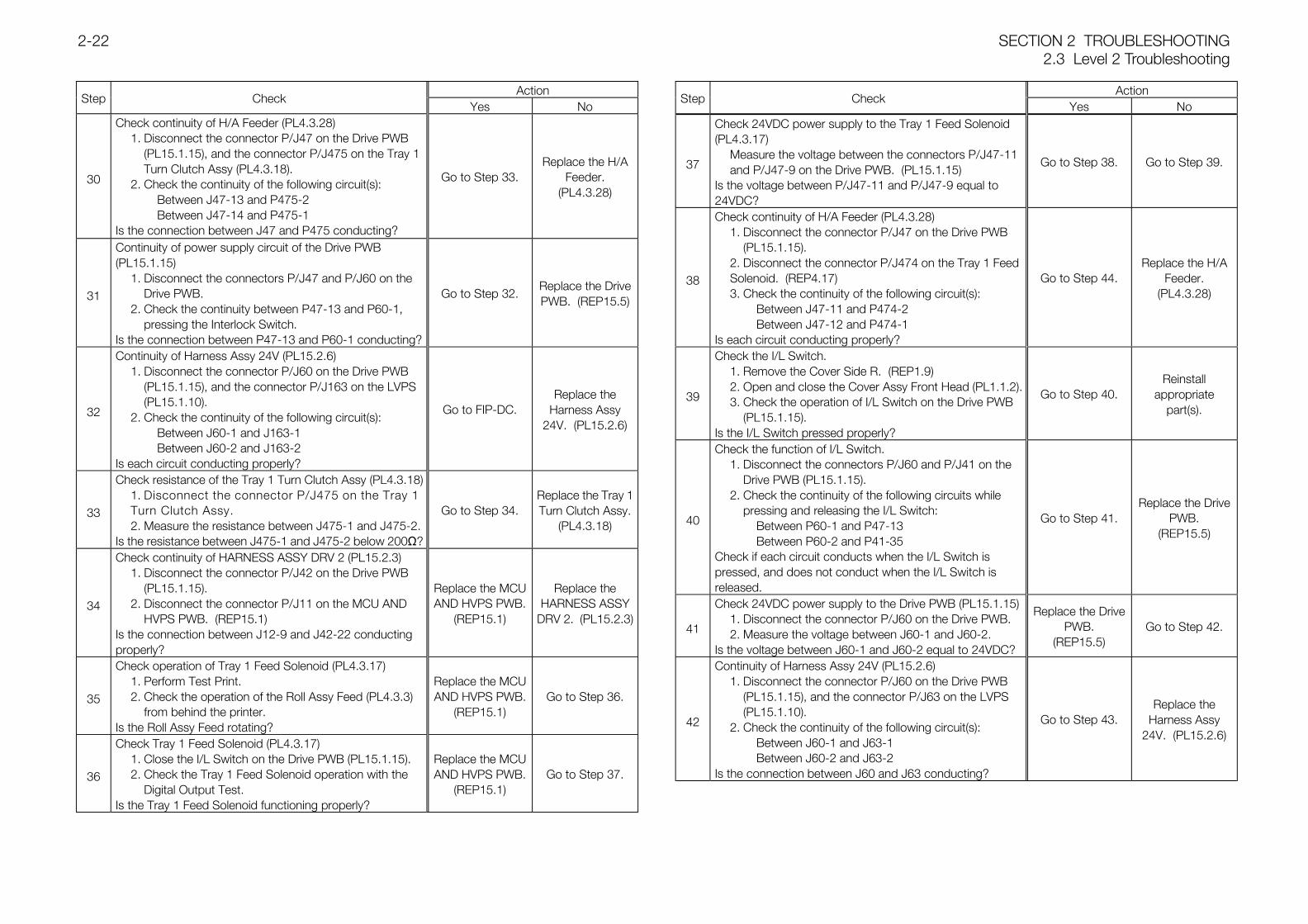
SECTION 2 TROUBLESHOOTING2.3 Level 2 Troubleshooting
2-22
ActionStep Check
Yes No
30
Check continuity of H/A Feeder (PL4.3.28)1. Disconnect the connector P/J47 on the Drive PWB
(PL15.1.15), and the connector P/J475 on the Tray 1 Turn Clutch Assy (PL4.3.18).
2. Check the continuity of the following circuit(s):Between J47-13 and P475-2Between J47-14 and P475-1
Is the connection between J47 and P475 conducting?
Go to Step 33.Replace the H/A
Feeder.(PL4.3.28)
31
Continuity of power supply circuit of the Drive PWB(PL15.1.15)
1. Disconnect the connectors P/J47 and P/J60 on the Drive PWB.
2. Check the continuity between P47-13 and P60-1, pressing the Interlock Switch.
Is the connection between P47-13 and P60-1 conducting?
Go to Step 32.Replace the DrivePWB. (REP15.5)
32
Continuity of Harness Assy 24V (PL15.2.6)1. Disconnect the connector P/J60 on the Drive PWB
(PL15.1.15), and the connector P/J163 on the LVPS (PL15.1.10).
2. Check the continuity of the following circuit(s):Between J60-1 and J163-1Between J60-2 and J163-2
Is each circuit conducting properly?
Go to FIP-DC.Replace the
Harness Assy24V. (PL15.2.6)
33
Check resistance of the Tray 1 Turn Clutch Assy (PL4.3.18)1. Disconnect the connector P/J475 on the Tray 1 Turn Clutch Assy.2. Measure the resistance between J475-1 and J475-2.
Is the resistance between J475-1 and J475-2 below 200Ω?
Go to Step 34.Replace the Tray 1Turn Clutch Assy.
(PL4.3.18)
34
Check continuity of HARNESS ASSY DRV 2 (PL15.2.3)1. Disconnect the connector P/J42 on the Drive PWB
(PL15.1.15).2. Disconnect the connector P/J11 on the MCU AND
HVPS PWB. (REP15.1)Is the connection between J12-9 and J42-22 conductingproperly?
Replace the MCUAND HVPS PWB.
(REP15.1)
Replace theHARNESS ASSY
DRV 2. (PL15.2.3)
35
Check operation of Tray 1 Feed Solenoid (PL4.3.17)1. Perform Test Print.2. Check the operation of the Roll Assy Feed (PL4.3.3)
from behind the printer.Is the Roll Assy Feed rotating?
Replace the MCUAND HVPS PWB.
(REP15.1)Go to Step 36.
36
Check Tray 1 Feed Solenoid (PL4.3.17)1. Close the I/L Switch on the Drive PWB (PL15.1.15).2. Check the Tray 1 Feed Solenoid operation with the
Digital Output Test.Is the Tray 1 Feed Solenoid functioning properly?
Replace the MCUAND HVPS PWB.
(REP15.1)Go to Step 37.
ActionStep Check
Yes No
37
Check 24VDC power supply to the Tray 1 Feed Solenoid(PL4.3.17)
Measure the voltage between the connectors P/J47-11 and P/J47-9 on the Drive PWB. (PL15.1.15)
Is the voltage between P/J47-11 and P/J47-9 equal to24VDC?
Go to Step 38. Go to Step 39.
38
Check continuity of H/A Feeder (PL4.3.28)1. Disconnect the connector P/J47 on the Drive PWB
(PL15.1.15).2. Disconnect the connector P/J474 on the Tray 1 Feed Solenoid. (REP4.17)3. Check the continuity of the following circuit(s):
Between J47-11 and P474-2Between J47-12 and P474-1
Is each circuit conducting properly?
Go to Step 44.Replace the H/A
Feeder.(PL4.3.28)
39
Check the I/L Switch.1. Remove the Cover Side R. (REP1.9)2. Open and close the Cover Assy Front Head (PL1.1.2).3. Check the operation of I/L Switch on the Drive PWB
(PL15.1.15).Is the I/L Switch pressed properly?
Go to Step 40.Reinstall
appropriatepart(s).
40
Check the function of I/L Switch.1. Disconnect the connectors P/J60 and P/J41 on the
Drive PWB (PL15.1.15).2. Check the continuity of the following circuits while
pressing and releasing the I/L Switch:Between P60-1 and P47-13Between P60-2 and P41-35
Check if each circuit conducts when the I/L Switch ispressed, and does not conduct when the I/L Switch isreleased.
Go to Step 41.Replace the Drive
PWB.(REP15.5)
41
Check 24VDC power supply to the Drive PWB (PL15.1.15)1. Disconnect the connector P/J60 on the Drive PWB.2. Measure the voltage between J60-1 and J60-2.
Is the voltage between J60-1 and J60-2 equal to 24VDC?
Replace the DrivePWB.
(REP15.5)Go to Step 42.
42
Continuity of Harness Assy 24V (PL15.2.6)1. Disconnect the connector P/J60 on the Drive PWB
(PL15.1.15), and the connector P/J63 on the LVPS (PL15.1.10).
2. Check the continuity of the following circuit(s):Between J60-1 and J63-1Between J60-2 and J63-2
Is the connection between J60 and J63 conducting?
Go to Step 43.Replace the
Harness Assy24V. (PL15.2.6)
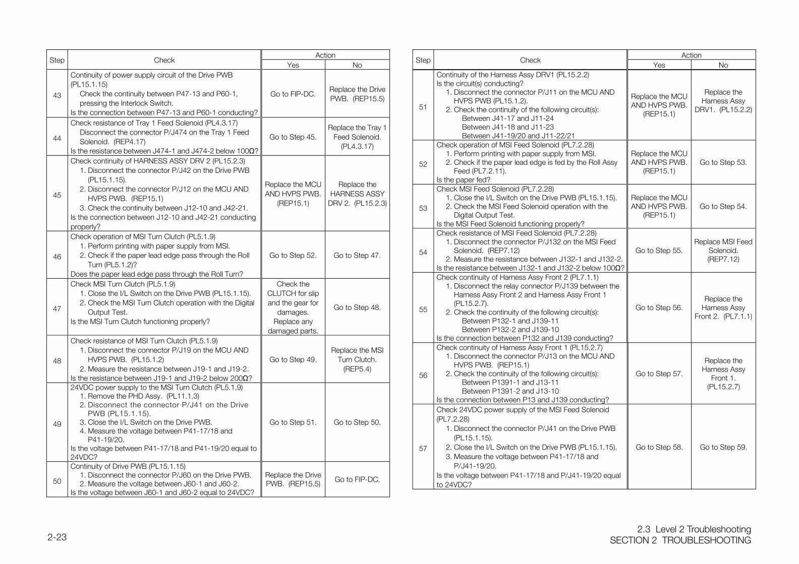
2.3 Level 2 TroubleshootingSECTION 2 TROUBLESHOOTING2-23
ActionStep Check
Yes No
43
Continuity of power supply circuit of the Drive PWB(PL15.1.15)
Check the continuity between P47-13 and P60-1, pressing the Interlock Switch.
Is the connection between P47-13 and P60-1 conducting?
Go to FIP-DC.Replace the DrivePWB. (REP15.5)
44
Check resistance of Tray 1 Feed Solenoid (PL4.3.17)Disconnect the connector P/J474 on the Tray 1 Feed Solenoid. (REP4.17)
Is the resistance between J474-1 and J474-2 below 100Ω?
Go to Step 45.Replace the Tray 1
Feed Solenoid.(PL4.3.17)
45
Check continuity of HARNESS ASSY DRV 2 (PL15.2.3)1. Disconnect the connector P/J42 on the Drive PWB
(PL15.1.15).2. Disconnect the connector P/J12 on the MCU AND
HVPS PWB. (REP15.1)3. Check the continuity between J12-10 and J42-21.
Is the connection between J12-10 and J42-21 conductingproperly?
Replace the MCUAND HVPS PWB.
(REP15.1)
Replace theHARNESS ASSY
DRV 2. (PL15.2.3)
46
Check operation of MSI Turn Clutch (PL5.1.9)1. Perform printing with paper supply from MSI.2. Check if the paper lead edge pass through the Roll
Turn (PL5.1.2)?Does the paper lead edge pass through the Roll Turn?
Go to Step 52. Go to Step 47.
47
Check MSI Turn Clutch (PL5.1.9)1. Close the I/L Switch on the Drive PWB (PL15.1.15).2. Check the MSI Turn Clutch operation with the Digital
Output Test.Is the MSI Turn Clutch functioning properly?
Check theCLUTCH for slipand the gear for
damages.Replace any
damaged parts.
Go to Step 48.
48
Check resistance of MSI Turn Clutch (PL5.1.9)1. Disconnect the connector P/J19 on the MCU AND
HVPS PWB. (PL15.1.2)2. Measure the resistance between J19-1 and J19-2.
Is the resistance between J19-1 and J19-2 below 200Ω?
Go to Step 49.Replace the MSI
Turn Clutch.(REP5.4)
49
24VDC power supply to the MSI Turn Clutch (PL5.1.9)1. Remove the PHD Assy. (PL11.1.3)2. Disconnect the connector P/J41 on the Drive
PWB (PL15.1.15).3. Close the I/L Switch on the Drive PWB.4. Measure the voltage between P41-17/18 and
P41-19/20.Is the voltage between P41-17/18 and P41-19/20 equal to24VDC?
Go to Step 51. Go to Step 50.
50
Continuity of Drive PWB (PL15.1.15)1. Disconnect the connector P/J60 on the Drive PWB.2. Measure the voltage between J60-1 and J60-2.
Is the voltage between J60-1 and J60-2 equal to 24VDC?
Replace the DrivePWB. (REP15.5) Go to FIP-DC.
ActionStep Check
Yes No
51
Continuity of the Harness Assy DRV1 (PL15.2.2)Is the circuit(s) conducting?
1. Disconnect the connector P/J11 on the MCU AND HVPS PWB (PL15.1.2).
2. Check the continuity of the following circuit(s):Between J41-17 and J11-24Between J41-18 and J11-23Between J41-19/20 and J11-22/21
Replace the MCUAND HVPS PWB.
(REP15.1)
Replace theHarness Assy
DRV1. (PL15.2.2)
52
Check operation of MSI Feed Solenoid (PL7.2.28)1. Perform printing with paper supply from MSI.2. Check if the paper lead edge is fed by the Roll Assy
Feed (PL7.2.11).Is the paper fed?
Replace the MCUAND HVPS PWB.
(REP15.1)Go to Step 53.
53
Check MSI Feed Solenoid (PL7.2.28)1. Close the I/L Switch on the Drive PWB (PL15.1.15).2. Check the MSI Feed Solenoid operation with the
Digital Output Test.Is the MSI Feed Solenoid functioning properly?
Replace the MCUAND HVPS PWB.
(REP15.1)Go to Step 54.
54
Check resistance of MSI Feed Solenoid (PL7.2.28)1. Disconnect the connector P/J132 on the MSI Feed
Solenoid. (REP7.12)2. Measure the resistance between J132-1 and J132-2.
Is the resistance between J132-1 and J132-2 below 100Ω?
Go to Step 55.Replace MSI Feed
Solenoid.(REP7.12)
55
Check continuity of Harness Assy Front 2 (PL7.1.1)1. Disconnect the relay connector P/J139 between the
Harness Assy Front 2 and Harness Assy Front 1 (PL15.2.7).
2. Check the continuity of the following circuit(s):Between P132-1 and J139-11Between P132-2 and J139-10
Is the connection between P132 and J139 conducting?
Go to Step 56.Replace the
Harness AssyFront 2. (PL7.1.1)
56
Check continuity of Harness Assy Front 1 (PL15.2.7)1. Disconnect the connector P/J13 on the MCU AND
HVPS PWB. (REP15.1)2. Check the continuity of the following circuit(s):
Between P1391-1 and J13-11Between P1391-2 and J13-10
Is the connection between P13 and J139 conducting?
Go to Step 57.
Replace theHarness Assy
Front 1.(PL15.2.7)
57
Check 24VDC power supply of the MSI Feed Solenoid(PL7.2.28)
1. Disconnect the connector P/J41 on the Drive PWB (PL15.1.15).
2. Close the I/L Switch on the Drive PWB (PL15.1.15).3. Measure the voltage between P41-17/18 and
P/J41-19/20.Is the voltage between P41-17/18 and P/J41-19/20 equalto 24VDC?
Go to Step 58. Go to Step 59.
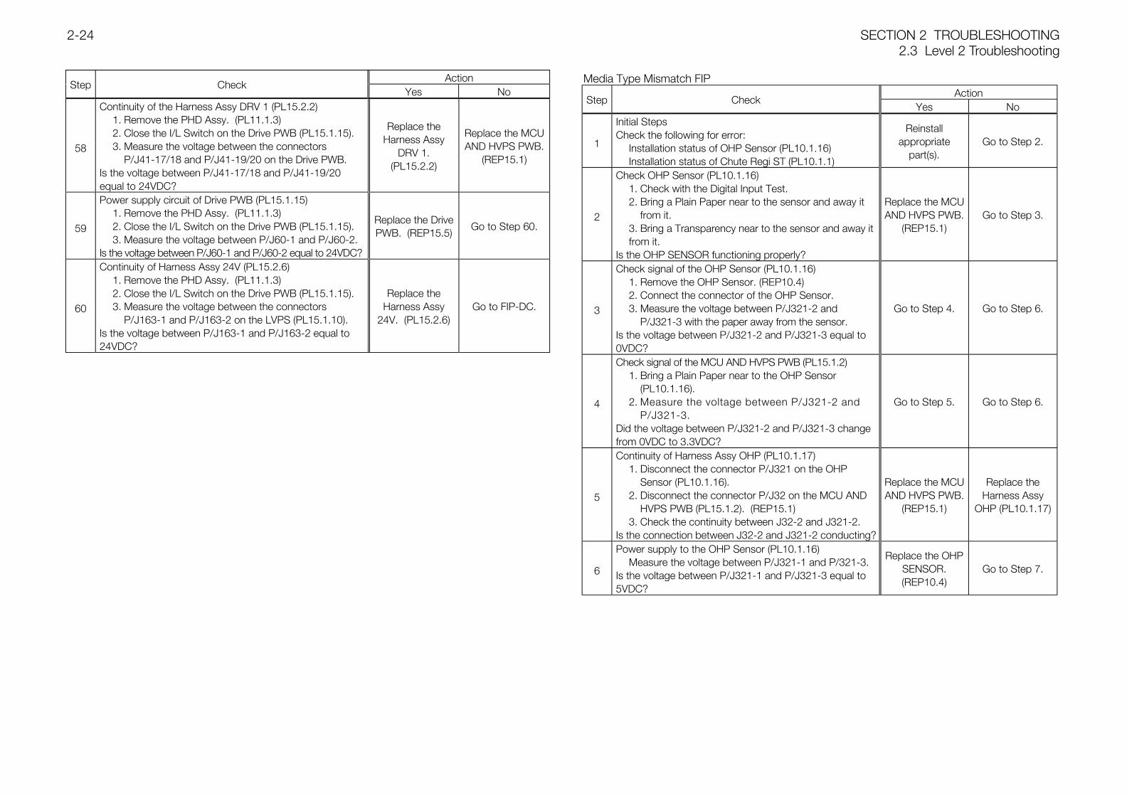
SECTION 2 TROUBLESHOOTING2.3 Level 2 Troubleshooting
2-24
ActionStep Check
Yes No
58
Continuity of the Harness Assy DRV 1 (PL15.2.2)1. Remove the PHD Assy. (PL11.1.3)2. Close the I/L Switch on the Drive PWB (PL15.1.15).3. Measure the voltage between the connectors
P/J41-17/18 and P/J41-19/20 on the Drive PWB.Is the voltage between P/J41-17/18 and P/J41-19/20equal to 24VDC?
Replace theHarness Assy
DRV 1.(PL15.2.2)
Replace the MCUAND HVPS PWB.
(REP15.1)
59
Power supply circuit of Drive PWB (PL15.1.15)1. Remove the PHD Assy. (PL11.1.3)2. Close the I/L Switch on the Drive PWB (PL15.1.15).3. Measure the voltage between P/J60-1 and P/J60-2.
Is the voltage between P/J60-1 and P/J60-2 equal to 24VDC?
Replace the DrivePWB. (REP15.5)
Go to Step 60.
60
Continuity of Harness Assy 24V (PL15.2.6)1. Remove the PHD Assy. (PL11.1.3)2. Close the I/L Switch on the Drive PWB (PL15.1.15).3. Measure the voltage between the connectors
P/J163-1 and P/J163-2 on the LVPS (PL15.1.10).Is the voltage between P/J163-1 and P/J163-2 equal to24VDC?
Replace theHarness Assy
24V. (PL15.2.6)Go to FIP-DC.
Media Type Mismatch FIPAction
Step CheckYes No
1
Initial StepsCheck the following for error:
Installation status of OHP Sensor (PL10.1.16)Installation status of Chute Regi ST (PL10.1.1)
Reinstallappropriate
part(s).Go to Step 2.
2
Check OHP Sensor (PL10.1.16)1. Check with the Digital Input Test.2. Bring a Plain Paper near to the sensor and away it
from it.3. Bring a Transparency near to the sensor and away it from it.
Is the OHP SENSOR functioning properly?
Replace the MCUAND HVPS PWB.
(REP15.1)Go to Step 3.
3
Check signal of the OHP Sensor (PL10.1.16)1. Remove the OHP Sensor. (REP10.4)2. Connect the connector of the OHP Sensor.3. Measure the voltage between P/J321-2 and
P/J321-3 with the paper away from the sensor.Is the voltage between P/J321-2 and P/J321-3 equal to0VDC?
Go to Step 4. Go to Step 6.
4
Check signal of the MCU AND HVPS PWB (PL15.1.2)1. Bring a Plain Paper near to the OHP Sensor
(PL10.1.16).2. Measure the voltage between P/J321-2 and
P/J321-3.Did the voltage between P/J321-2 and P/J321-3 changefrom 0VDC to 3.3VDC?
Go to Step 5. Go to Step 6.
5
Continuity of Harness Assy OHP (PL10.1.17)1. Disconnect the connector P/J321 on the OHP
Sensor (PL10.1.16).2. Disconnect the connector P/J32 on the MCU AND
HVPS PWB (PL15.1.2). (REP15.1)3. Check the continuity between J32-2 and J321-2.
Is the connection between J32-2 and J321-2 conducting?
Replace the MCUAND HVPS PWB.
(REP15.1)
Replace theHarness Assy
OHP (PL10.1.17)
6
Power supply to the OHP Sensor (PL10.1.16)Measure the voltage between P/J321-1 and P/321-3.
Is the voltage between P/J321-1 and P/J321-3 equal to5VDC?
Replace the OHPSENSOR.(REP10.4)
Go to Step 7.
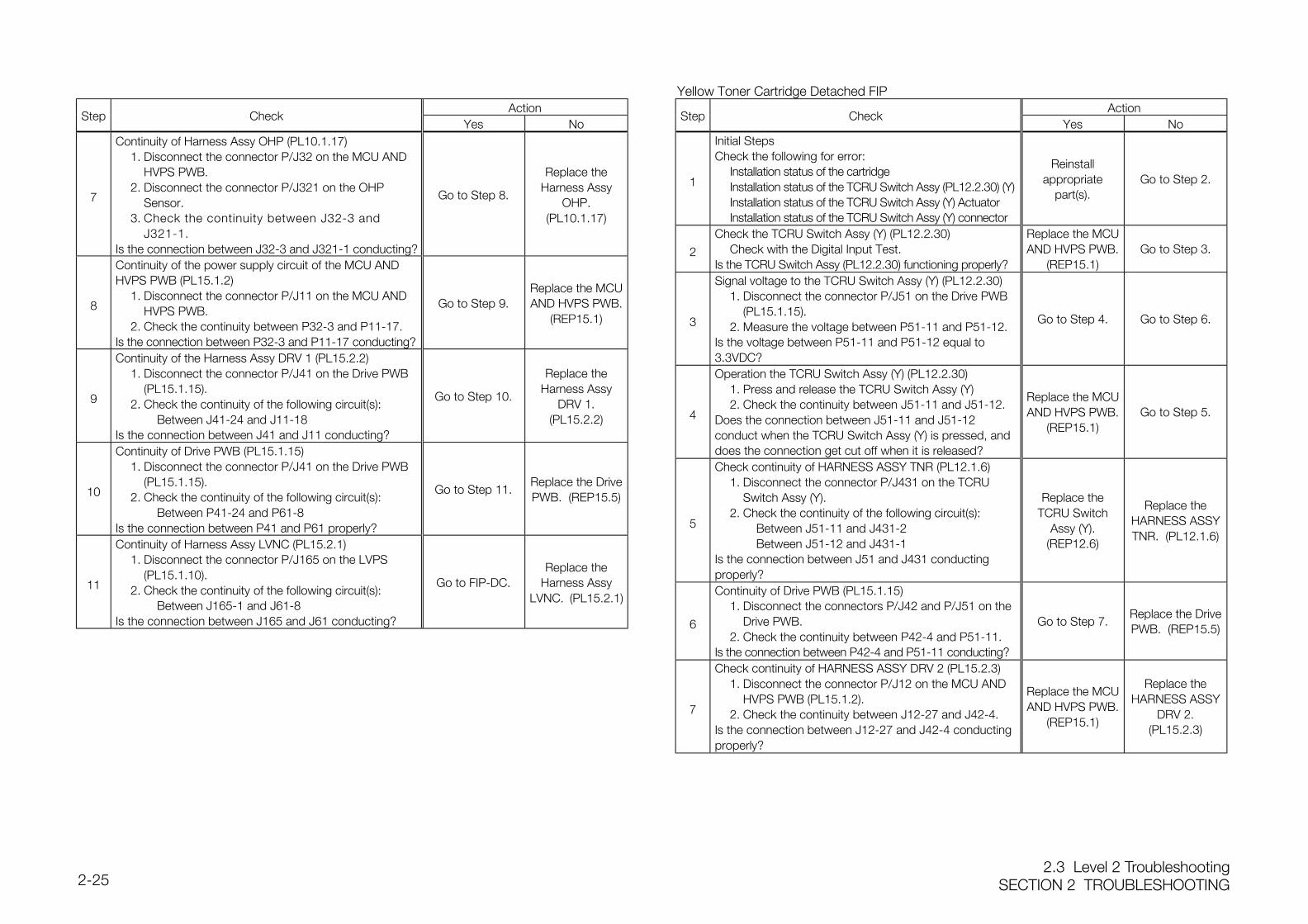
2.3 Level 2 TroubleshootingSECTION 2 TROUBLESHOOTING2-25
ActionStep Check
Yes No
7
Continuity of Harness Assy OHP (PL10.1.17)1. Disconnect the connector P/J32 on the MCU AND
HVPS PWB.2. Disconnect the connector P/J321 on the OHP
Sensor.3. Check the continuity between J32-3 and
J321-1.Is the connection between J32-3 and J321-1 conducting?
Go to Step 8.
Replace theHarness Assy
OHP.(PL10.1.17)
8
Continuity of the power supply circuit of the MCU ANDHVPS PWB (PL15.1.2)
1. Disconnect the connector P/J11 on the MCU AND HVPS PWB.
2. Check the continuity between P32-3 and P11-17.Is the connection between P32-3 and P11-17 conducting?
Go to Step 9.Replace the MCUAND HVPS PWB.
(REP15.1)
9
Continuity of the Harness Assy DRV 1 (PL15.2.2)1. Disconnect the connector P/J41 on the Drive PWB
(PL15.1.15).2. Check the continuity of the following circuit(s):
Between J41-24 and J11-18Is the connection between J41 and J11 conducting?
Go to Step 10.
Replace theHarness Assy
DRV 1.(PL15.2.2)
10
Continuity of Drive PWB (PL15.1.15)1. Disconnect the connector P/J41 on the Drive PWB
(PL15.1.15).2. Check the continuity of the following circuit(s):
Between P41-24 and P61-8Is the connection between P41 and P61 properly?
Go to Step 11.Replace the DrivePWB. (REP15.5)
11
Continuity of Harness Assy LVNC (PL15.2.1)1. Disconnect the connector P/J165 on the LVPS
(PL15.1.10).2. Check the continuity of the following circuit(s):
Between J165-1 and J61-8Is the connection between J165 and J61 conducting?
Go to FIP-DC.Replace the
Harness AssyLVNC. (PL15.2.1)
Yellow Toner Cartridge Detached FIPAction
Step CheckYes No
1
Initial StepsCheck the following for error:
Installation status of the cartridgeInstallation status of the TCRU Switch Assy (PL12.2.30) (Y)Installation status of the TCRU Switch Assy (Y) ActuatorInstallation status of the TCRU Switch Assy (Y) connector
Reinstallappropriate
part(s).Go to Step 2.
2
Check the TCRU Switch Assy (Y) (PL12.2.30)Check with the Digital Input Test.
Is the TCRU Switch Assy (PL12.2.30) functioning properly?
Replace the MCUAND HVPS PWB.
(REP15.1)Go to Step 3.
3
Signal voltage to the TCRU Switch Assy (Y) (PL12.2.30)1. Disconnect the connector P/J51 on the Drive PWB
(PL15.1.15).2. Measure the voltage between P51-11 and P51-12.
Is the voltage between P51-11 and P51-12 equal to3.3VDC?
Go to Step 4. Go to Step 6.
4
Operation the TCRU Switch Assy (Y) (PL12.2.30)1. Press and release the TCRU Switch Assy (Y)2. Check the continuity between J51-11 and J51-12.
Does the connection between J51-11 and J51-12conduct when the TCRU Switch Assy (Y) is pressed, anddoes the connection get cut off when it is released?
Replace the MCUAND HVPS PWB.
(REP15.1)Go to Step 5.
5
Check continuity of HARNESS ASSY TNR (PL12.1.6)1. Disconnect the connector P/J431 on the TCRU
Switch Assy (Y).2. Check the continuity of the following circuit(s):
Between J51-11 and J431-2Between J51-12 and J431-1
Is the connection between J51 and J431 conductingproperly?
Replace theTCRU Switch
Assy (Y).(REP12.6)
Replace theHARNESS ASSYTNR. (PL12.1.6)
6
Continuity of Drive PWB (PL15.1.15)1. Disconnect the connectors P/J42 and P/J51 on the
Drive PWB.2. Check the continuity between P42-4 and P51-11.
Is the connection between P42-4 and P51-11 conducting?
Go to Step 7.Replace the DrivePWB. (REP15.5)
7
Check continuity of HARNESS ASSY DRV 2 (PL15.2.3)1. Disconnect the connector P/J12 on the MCU AND
HVPS PWB (PL15.1.2).2. Check the continuity between J12-27 and J42-4.
Is the connection between J12-27 and J42-4 conductingproperly?
Replace the MCUAND HVPS PWB.
(REP15.1)
Replace theHARNESS ASSY
DRV 2.(PL15.2.3)
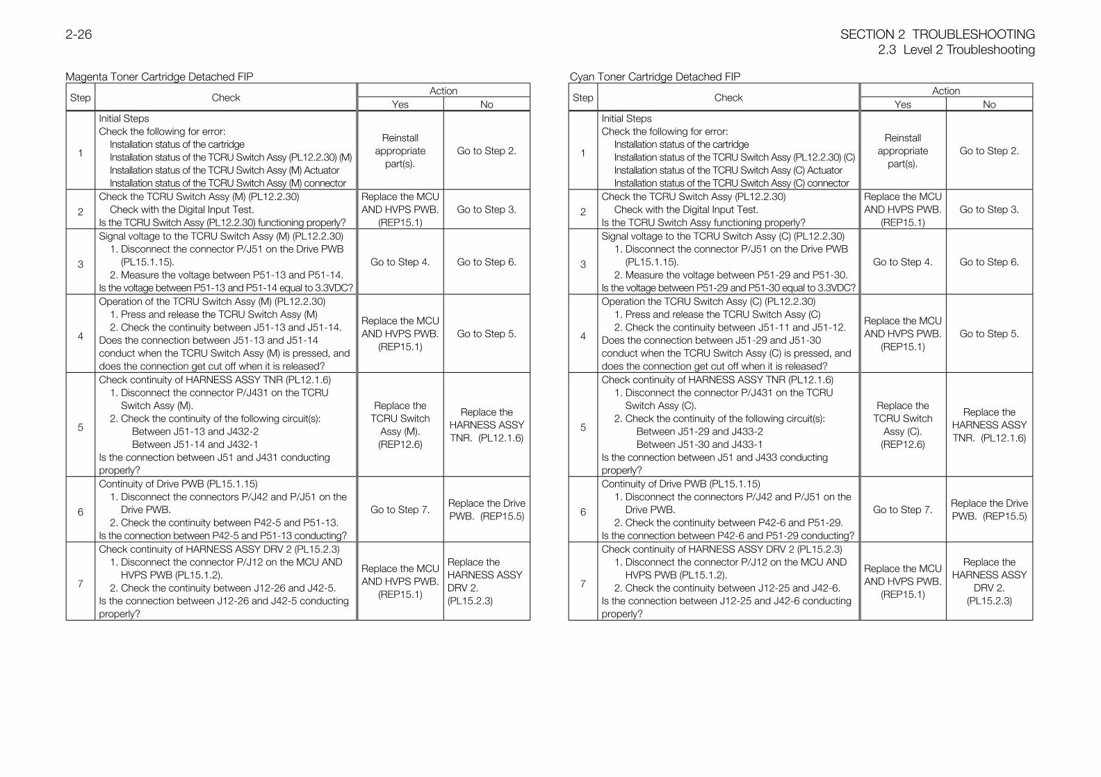
SECTION 2 TROUBLESHOOTING2.3 Level 2 Troubleshooting
2-26
Magenta Toner Cartridge Detached FIPAction
Step CheckYes No
1
Initial StepsCheck the following for error:
Installation status of the cartridgeInstallation status of the TCRU Switch Assy (PL12.2.30) (M)Installation status of the TCRU Switch Assy (M) ActuatorInstallation status of the TCRU Switch Assy (M) connector
Reinstallappropriate
part(s).Go to Step 2.
2
Check the TCRU Switch Assy (M) (PL12.2.30)Check with the Digital Input Test.
Is the TCRU Switch Assy (PL12.2.30) functioning properly?
Replace the MCUAND HVPS PWB.
(REP15.1)Go to Step 3.
3
Signal voltage to the TCRU Switch Assy (M) (PL12.2.30)1. Disconnect the connector P/J51 on the Drive PWB
(PL15.1.15).2. Measure the voltage between P51-13 and P51-14.
Is the voltage between P51-13 and P51-14 equal to 3.3VDC?
Go to Step 4. Go to Step 6.
4
Operation of the TCRU Switch Assy (M) (PL12.2.30)1. Press and release the TCRU Switch Assy (M)2. Check the continuity between J51-13 and J51-14.
Does the connection between J51-13 and J51-14conduct when the TCRU Switch Assy (M) is pressed, anddoes the connection get cut off when it is released?
Replace the MCUAND HVPS PWB.
(REP15.1)Go to Step 5.
5
Check continuity of HARNESS ASSY TNR (PL12.1.6)1. Disconnect the connector P/J431 on the TCRU
Switch Assy (M).2. Check the continuity of the following circuit(s):
Between J51-13 and J432-2Between J51-14 and J432-1
Is the connection between J51 and J431 conductingproperly?
Replace theTCRU Switch
Assy (M).(REP12.6)
Replace theHARNESS ASSYTNR. (PL12.1.6)
6
Continuity of Drive PWB (PL15.1.15)1. Disconnect the connectors P/J42 and P/J51 on the
Drive PWB.2. Check the continuity between P42-5 and P51-13.
Is the connection between P42-5 and P51-13 conducting?
Go to Step 7.Replace the DrivePWB. (REP15.5)
7
Check continuity of HARNESS ASSY DRV 2 (PL15.2.3)1. Disconnect the connector P/J12 on the MCU AND
HVPS PWB (PL15.1.2).2. Check the continuity between J12-26 and J42-5.
Is the connection between J12-26 and J42-5 conductingproperly?
Replace the MCUAND HVPS PWB.
(REP15.1)
Replace theHARNESS ASSYDRV 2.(PL15.2.3)
Cyan Toner Cartridge Detached FIPAction
Step CheckYes No
1
Initial StepsCheck the following for error:
Installation status of the cartridgeInstallation status of the TCRU Switch Assy (PL12.2.30) (C)Installation status of the TCRU Switch Assy (C) ActuatorInstallation status of the TCRU Switch Assy (C) connector
Reinstallappropriate
part(s).Go to Step 2.
2
Check the TCRU Switch Assy (PL12.2.30)Check with the Digital Input Test.
Is the TCRU Switch Assy functioning properly?
Replace the MCUAND HVPS PWB.
(REP15.1)Go to Step 3.
3
Signal voltage to the TCRU Switch Assy (C) (PL12.2.30)1. Disconnect the connector P/J51 on the Drive PWB
(PL15.1.15).2. Measure the voltage between P51-29 and P51-30.
Is the voltage between P51-29 and P51-30 equal to 3.3VDC?
Go to Step 4. Go to Step 6.
4
Operation the TCRU Switch Assy (C) (PL12.2.30)1. Press and release the TCRU Switch Assy (C)2. Check the continuity between J51-11 and J51-12.
Does the connection between J51-29 and J51-30conduct when the TCRU Switch Assy (C) is pressed, anddoes the connection get cut off when it is released?
Replace the MCUAND HVPS PWB.
(REP15.1)Go to Step 5.
5
Check continuity of HARNESS ASSY TNR (PL12.1.6)1. Disconnect the connector P/J431 on the TCRU
Switch Assy (C).2. Check the continuity of the following circuit(s):
Between J51-29 and J433-2Between J51-30 and J433-1
Is the connection between J51 and J433 conductingproperly?
Replace theTCRU Switch
Assy (C).(REP12.6)
Replace theHARNESS ASSYTNR. (PL12.1.6)
6
Continuity of Drive PWB (PL15.1.15)1. Disconnect the connectors P/J42 and P/J51 on the
Drive PWB.2. Check the continuity between P42-6 and P51-29.
Is the connection between P42-6 and P51-29 conducting?
Go to Step 7.Replace the DrivePWB. (REP15.5)
7
Check continuity of HARNESS ASSY DRV 2 (PL15.2.3)1. Disconnect the connector P/J12 on the MCU AND
HVPS PWB (PL15.1.2).2. Check the continuity between J12-25 and J42-6.
Is the connection between J12-25 and J42-6 conductingproperly?
Replace the MCUAND HVPS PWB.
(REP15.1)
Replace theHARNESS ASSY
DRV 2.(PL15.2.3)
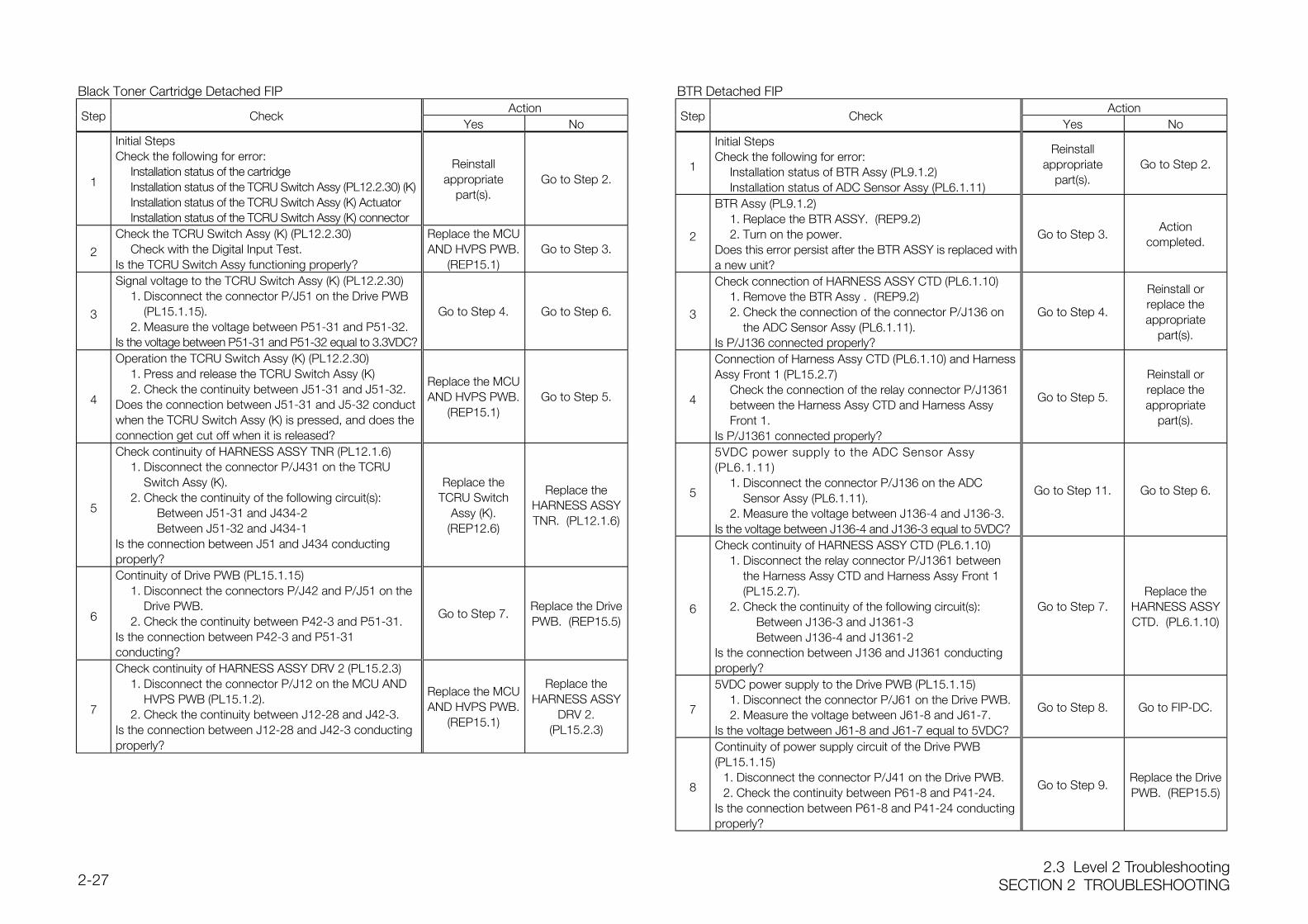
2.3 Level 2 TroubleshootingSECTION 2 TROUBLESHOOTING2-27
Black Toner Cartridge Detached FIPAction
Step CheckYes No
1
Initial StepsCheck the following for error:
Installation status of the cartridgeInstallation status of the TCRU Switch Assy (PL12.2.30) (K)Installation status of the TCRU Switch Assy (K) ActuatorInstallation status of the TCRU Switch Assy (K) connector
Reinstallappropriate
part(s).Go to Step 2.
2
Check the TCRU Switch Assy (K) (PL12.2.30)Check with the Digital Input Test.
Is the TCRU Switch Assy functioning properly?
Replace the MCUAND HVPS PWB.
(REP15.1)Go to Step 3.
3
Signal voltage to the TCRU Switch Assy (K) (PL12.2.30)1. Disconnect the connector P/J51 on the Drive PWB
(PL15.1.15).2. Measure the voltage between P51-31 and P51-32.
Is the voltage between P51-31 and P51-32 equal to 3.3VDC?
Go to Step 4. Go to Step 6.
4
Operation the TCRU Switch Assy (K) (PL12.2.30)1. Press and release the TCRU Switch Assy (K)2. Check the continuity between J51-31 and J51-32.
Does the connection between J51-31 and J5-32 conductwhen the TCRU Switch Assy (K) is pressed, and does theconnection get cut off when it is released?
Replace the MCUAND HVPS PWB.
(REP15.1)Go to Step 5.
5
Check continuity of HARNESS ASSY TNR (PL12.1.6)1. Disconnect the connector P/J431 on the TCRU
Switch Assy (K).2. Check the continuity of the following circuit(s):
Between J51-31 and J434-2Between J51-32 and J434-1
Is the connection between J51 and J434 conductingproperly?
Replace theTCRU Switch
Assy (K).(REP12.6)
Replace theHARNESS ASSYTNR. (PL12.1.6)
6
Continuity of Drive PWB (PL15.1.15)1. Disconnect the connectors P/J42 and P/J51 on the
Drive PWB.2. Check the continuity between P42-3 and P51-31.
Is the connection between P42-3 and P51-31conducting?
Go to Step 7.Replace the DrivePWB. (REP15.5)
7
Check continuity of HARNESS ASSY DRV 2 (PL15.2.3)1. Disconnect the connector P/J12 on the MCU AND
HVPS PWB (PL15.1.2).2. Check the continuity between J12-28 and J42-3.
Is the connection between J12-28 and J42-3 conductingproperly?
Replace the MCUAND HVPS PWB.
(REP15.1)
Replace theHARNESS ASSY
DRV 2.(PL15.2.3)
BTR Detached FIPAction
Step CheckYes No
1
Initial StepsCheck the following for error:
Installation status of BTR Assy (PL9.1.2)Installation status of ADC Sensor Assy (PL6.1.11)
Reinstallappropriate
part(s).Go to Step 2.
2
BTR Assy (PL9.1.2)1. Replace the BTR ASSY. (REP9.2)2. Turn on the power.
Does this error persist after the BTR ASSY is replaced witha new unit?
Go to Step 3.Action
completed.
3
Check connection of HARNESS ASSY CTD (PL6.1.10)1. Remove the BTR Assy . (REP9.2)2. Check the connection of the connector P/J136 on
the ADC Sensor Assy (PL6.1.11).Is P/J136 connected properly?
Go to Step 4.
Reinstall orreplace theappropriate
part(s).
4
Connection of Harness Assy CTD (PL6.1.10) and HarnessAssy Front 1 (PL15.2.7)
Check the connection of the relay connector P/J1361 between the Harness Assy CTD and Harness Assy Front 1.
Is P/J1361 connected properly?
Go to Step 5.
Reinstall orreplace theappropriate
part(s).
5
5VDC power supply to the ADC Sensor Assy(PL6.1.11)
1. Disconnect the connector P/J136 on the ADC Sensor Assy (PL6.1.11).
2. Measure the voltage between J136-4 and J136-3.Is the voltage between J136-4 and J136-3 equal to 5VDC?
Go to Step 11. Go to Step 6.
6
Check continuity of HARNESS ASSY CTD (PL6.1.10)1. Disconnect the relay connector P/J1361 between
the Harness Assy CTD and Harness Assy Front 1 (PL15.2.7).
2. Check the continuity of the following circuit(s):Between J136-3 and J1361-3Between J136-4 and J1361-2
Is the connection between J136 and J1361 conductingproperly?
Go to Step 7.Replace the
HARNESS ASSYCTD. (PL6.1.10)
7
5VDC power supply to the Drive PWB (PL15.1.15)1. Disconnect the connector P/J61 on the Drive PWB.2. Measure the voltage between J61-8 and J61-7.
Is the voltage between J61-8 and J61-7 equal to 5VDC?
Go to Step 8. Go to FIP-DC.
8
Continuity of power supply circuit of the Drive PWB(PL15.1.15)
1. Disconnect the connector P/J41 on the Drive PWB.2. Check the continuity between P61-8 and P41-24.
Is the connection between P61-8 and P41-24 conductingproperly?
Go to Step 9.Replace the DrivePWB. (REP15.5)
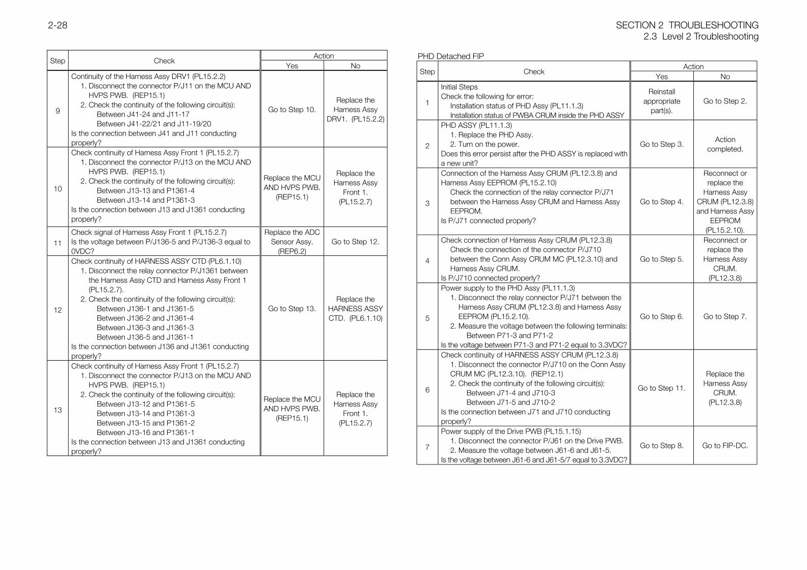
SECTION 2 TROUBLESHOOTING2.3 Level 2 Troubleshooting
2-28
ActionStep Check
Yes No
9
Continuity of the Harness Assy DRV1 (PL15.2.2)1. Disconnect the connector P/J11 on the MCU AND
HVPS PWB. (REP15.1)2. Check the continuity of the following circuit(s):
Between J41-24 and J11-17Between J41-22/21 and J11-19/20
Is the connection between J41 and J11 conductingproperly?
Go to Step 10.Replace the
Harness AssyDRV1. (PL15.2.2)
10
Check continuity of Harness Assy Front 1 (PL15.2.7)1. Disconnect the connector P/J13 on the MCU AND
HVPS PWB. (REP15.1)2. Check the continuity of the following circuit(s):
Between J13-13 and P1361-4Between J13-14 and P1361-3
Is the connection between J13 and J1361 conductingproperly?
Replace the MCUAND HVPS PWB.
(REP15.1)
Replace theHarness Assy
Front 1.(PL15.2.7)
11Check signal of Harness Assy Front 1 (PL15.2.7)Is the voltage between P/J136-5 and P/J136-3 equal to0VDC?
Replace the ADCSensor Assy.
(REP6.2)Go to Step 12.
12
Check continuity of HARNESS ASSY CTD (PL6.1.10)1. Disconnect the relay connector P/J1361 between
the Harness Assy CTD and Harness Assy Front 1 (PL15.2.7).
2. Check the continuity of the following circuit(s):Between J136-1 and J1361-5Between J136-2 and J1361-4Between J136-3 and J1361-3Between J136-5 and J1361-1
Is the connection between J136 and J1361 conductingproperly?
Go to Step 13.Replace the
HARNESS ASSYCTD. (PL6.1.10)
13
Check continuity of Harness Assy Front 1 (PL15.2.7)1. Disconnect the connector P/J13 on the MCU AND
HVPS PWB. (REP15.1)2. Check the continuity of the following circuit(s):
Between J13-12 and P1361-5Between J13-14 and P1361-3Between J13-15 and P1361-2Between J13-16 and P1361-1
Is the connection between J13 and J1361 conductingproperly?
Replace the MCUAND HVPS PWB.
(REP15.1)
Replace theHarness Assy
Front 1.(PL15.2.7)
PHD Detached FIPAction
Step CheckYes No
1
Initial StepsCheck the following for error:
Installation status of PHD Assy (PL11.1.3)Installation status of PWBA CRUM inside the PHD ASSY
Reinstallappropriate
part(s).Go to Step 2.
2
PHD ASSY (PL11.1.3)1. Replace the PHD Assy.2. Turn on the power.
Does this error persist after the PHD ASSY is replaced witha new unit?
Go to Step 3.Action
completed.
3
Connection of the Harness Assy CRUM (PL12.3.8) andHarness Assy EEPROM (PL15.2.10)
Check the connection of the relay connector P/J71 between the Harness Assy CRUM and Harness Assy EEPROM.
Is P/J71 connected properly?
Go to Step 4.
Reconnect orreplace the
Harness AssyCRUM (PL12.3.8)and Harness Assy
EEPROM(PL15.2.10).
4
Check connection of Harness Assy CRUM (PL12.3.8)Check the connection of the connector P/J710 between the Conn Assy CRUM MC (PL12.3.10) and Harness Assy CRUM.
Is P/J710 connected properly?
Go to Step 5.
Reconnect orreplace the
Harness AssyCRUM.
(PL12.3.8)
5
Power supply to the PHD Assy (PL11.1.3)1. Disconnect the relay connector P/J71 between the
Harness Assy CRUM (PL12.3.8) and Harness Assy EEPROM (PL15.2.10).
2. Measure the voltage between the following terminals:Between P71-3 and P71-2
Is the voltage between P71-3 and P71-2 equal to 3.3VDC?
Go to Step 6. Go to Step 7.
6
Check continuity of HARNESS ASSY CRUM (PL12.3.8)1. Disconnect the connector P/J710 on the Conn Assy CRUM MC (PL12.3.10). (REP12.1)2. Check the continuity of the following circuit(s):
Between J71-4 and J710-3Between J71-5 and J710-2
Is the connection between J71 and J710 conductingproperly?
Go to Step 11.
Replace theHarness Assy
CRUM.(PL12.3.8)
7
Power supply of the Drive PWB (PL15.1.15)1. Disconnect the connector P/J61 on the Drive PWB.2. Measure the voltage between J61-6 and J61-5.
Is the voltage between J61-6 and J61-5/7 equal to 3.3VDC?
Go to Step 8. Go to FIP-DC.
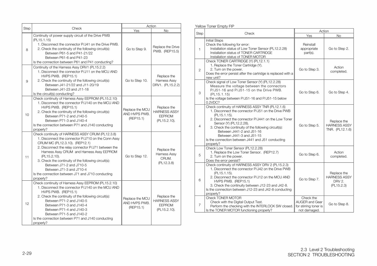
2.3 Level 2 TroubleshootingSECTION 2 TROUBLESHOOTING2-29
ActionStep Check
Yes No
8
Continuity of power supply circuit of the Drive PWB(PL15.1.15)
1. Disconnect the connector P/J41 on the Drive PWB.2. Check the continuity of the following circuit(s):
Between P61-5 and P41-21/22Between P61-6 and P41-23
Is the connection between P61 and P41 conducting?
Go to Step 9.Replace the DrivePWB. (REP15.5)
9
Continuity of the Harness Assy DRV1 (PL15.2.2)1. Disconnect the connector P/J11 on the MCU AND
HVPS PWB. (REP15.1)2. Check the continuity of the following circuit(s):
Between J41-21/22 and J11-20/19Between J41-23 and J11-18
Is the circuit(s) conducting?
Go to Step 10.Replace the
Harness AssyDRV1. (PL15.2.2)
10
Check continuity of Harness Assy EEPROM (PL15.2.10)1. Disconnect the connector P/J140 on the MCU AND
HVPS PWB. (REP15.1)2. Check the continuity of the following circuit(s):
Between P71-2 and J140-5Between P71-3 and J140-4
Is the connection between P71 and J140 conductingproperly?
Replace the MCUAND HVPS PWB.
(REP15.1)
Replace theHARNESS ASSY
EEPROM(PL15.2.10).
11
Check continuity of HARNESS ASSY CRUM (PL12.3.8)1. Disconnect the connector P/J710 on the Conn Assy CRUM MC (PL12.3.10). (REP12.1)2. Disconnect the relay connector P/J71 between the
Harness Assy CRUM and Harness Assy EEPROM (PL15.2.10).
3. Check the continuity of the following circuit(s):Between J71-2 and J710-5Between J71-3 and J710-4
Is the connection between J71 and J710 conductingproperly?
Go to Step 12.
Replace theHarness Assy
CRUM.(PL12.3.8)
12
Check continuity of Harness Assy EEPROM (PL15.2.10)1. Disconnect the connector P/J140 on the MCU AND
HVPS PWB. (REP15.1)2. Check the continuity of the following circuit(s):
Between P71-2 and J140-5Between P71-3 and J140-4Between P71-4 and J140-3Between P71-5 and J140-2
Is the connection between P71 and J140 conductingproperly?
Replace the MCUAND HVPS PWB.
(REP15.1)
Replace theHARNESS ASSY
EEPROM(PL15.2.10).
Yellow Toner Empty FIPAction
Step CheckYes No
1
Initial StepsCheck the following for error:
Installation status of Low Toner Sensor (PL12.2.28)Installation status of TONER CARTRIDGEInstallation status of TONER MOTOR
Reinstallappropriate
part(s).Go to Step 2.
2
Check TONER CARTRIDGE (Y) (PL12.1.1)1. Replace the Toner Cartridge (Y).2. Turn on the power.
Does the error persist after the cartridge is replaced with anew unit?
Go to Step 3.Action
completed.
3
Check signal of Low Toner Sensor (Y) (PL12.2.28)Measure the voltage between the connectors P/J51-16 and P/J51-15 on the Drive PWB. (PL15.1.15)
Is the voltage between P/J51-16 and P/J51-15 below0.2VDC?
Go to Step 6. Go to Step 4.
4
Check continuity of HARNESS ASSY TNR (PL12.1.6)1. Disconnect the connector P/J51 on the Drive PWB
(PL15.1.15).2. Disconnect the connector P/J441 on the Low Toner
Sensor (Y) (PL12.2.28).3. Check the continuity of the following circuit(s):
Between J441-2 and J51-16Between J441-3 and J51-15
Is the connection between J441 and J51 conductingproperly?
Go to Step 5.Replace the
HARNESS ASSYTNR. (PL12.1.6)
5
Check Low Toner Sensor (PL12.2.28)1. Replace the Low Toner Sensor. (REP12.7)2. Turn on the power.
Does the error persist?
Go to Step 6.Action
completed.
6
Check continuity of HARNESS ASSY DRV 2 (PL15.2.3)1. Disconnect the connector P/J42 on the Drive PWB
(PL15.1.15).2. Disconnect the connector P/J12 on the MCU AND
HVPS PWB. (REP15.1)3. Check the continuity between J12-23 and J42-8.
Is the connection between J12-23 and J42-8 conductingproperly?
Go to Step 7.
Replace theHARNESS ASSY
DRV 2.(PL15.2.3)
7
Check TONER MOTORCheck with the Digital Output Test.Perform the checking with the INTERLOCK SW closed.
Is the TONER MOTOR functioning properly?
Check theAUGER and Gearfor stirring toner is
not damaged.
Go to Step 8.
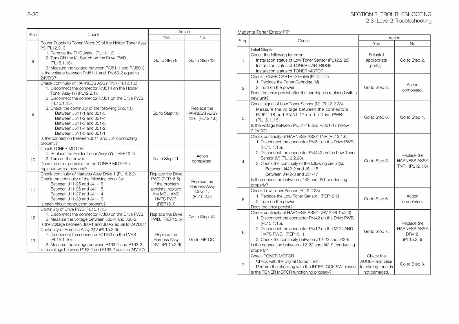
SECTION 2 TROUBLESHOOTING2.3 Level 2 Troubleshooting
2-30
ActionStep Check
Yes No
8
Power Supply to Toner Motor (Y) of the Holder Toner Assy(Y) (PL12.2.1)
1. Remove the PHD Assy. (PL11.1.3)2. Turn ON the I/L Switch on the Drive PWB
(PL15.1.15).3. Measure the voltage between P/J51-1 and P/J60-2.
Is the voltage between P/J51-1 and P/J60-2 equal to24VDC?
Go to Step 9. Go to Step 12.
9
Check continuity of HARNESS ASSY TNR (PL12.1.6)1. Disconnect the connector P/J514 on the Holder
Toner Assy (Y) (PL12.2.1).2. Disconnect the connector P/J51 on the Drive PWB
(PL15.1.15).3. Check the continuity of the following circuit(s):
Between J511-1 and J51-5Between J511-2 and J51-4Between J511-3 and J51-3Between J511-4 and J51-2Between J511-5 and J51-1
Is the connection between J511 and J51 conductingproperly?
Go to Step 10.Replace the
HARNESS ASSYTNR. (PL12.1.6)
10
Check TONER MOTOR1. Replace the Holder Toner Assy (Y). (REP12.2)2. Turn on the power.
Does the error persist after the TONER MOTOR isreplaced with a new unit?
Go to Step 11.Action
completed.
11
Check continuity of Harness Assy Drive 1 (PL15.2.2)Check the continuity of the following circuit(s):
Between J11-25 and J41-16Between J11-26 and J41-15Between J11-27 and J41-14Between J11-28 and J41-13
Is each circuit conducting properly?
Replace the DrivePWB (REP15.5).
If the problempersists, replacethe MCU ANDHVPS PWB.(REP15.1)
Replace theHarness Assy
Drive 1.(PL15.2.2)
12
Continuity of Drive PWB (PL15.1.15)1. Disconnect the connector P/J60 on the Drive PWB.2. Measure the voltage between J60-1 and J60-2.
Is the voltage between J60-1 and J60-2 equal to 24VDC?
Replace the DrivePWB. (REP15.5) Go to Step 13.
13
Continuity of Harness Assy 24V (PL15.2.6)1. Disconnect the connector P/J163 on the LVPS
(PL15.1.10).2. Measure the voltage between P163-1 and P163-2.
Is the voltage between P163-1 and P163-2 equal to 24VDC?
Replace theHarness Assy
24V. (PL15.2.6)Go to FIP-DC.
Magenta Toner Empty FIPAction
Step CheckYes No
1
Initial StepsCheck the following for error:
Installation status of Low Toner Sensor (PL12.2.28)Installation status of TONER CARTRIDGEInstallation status of TONER MOTOR
Reinstallappropriate
part(s).Go to Step 2.
2
Check TONER CARTRIDGE (M) (PL12.1.2)1. Replace the Toner Cartridge (M).2. Turn on the power.
Does the error persist after the cartridge is replaced with anew unit?
Go to Step 3.Action
completed.
3
Check signal of Low Toner Sensor (M) (PL12.2.28)Measure the voltage between the connectors P/J51-18 and P/J51-17 on the Drive PWB. (PL15.1.15)
Is the voltage between P/J51-18 and P/J51-17 below0.2VDC?
Go to Step 6. Go to Step 4.
4
Check continuity of HARNESS ASSY TNR (PL12.1.6)1. Disconnect the connector P/J51 on the Drive PWB
(PL15.1.15).2. Disconnect the connector P/J442 on the Low Toner
Sensor (M) (PL12.2.28).3. Check the continuity of the following circuit(s):
Between J442-2 and J51-18Between J442-3 and J51-17
Is the connection between J442 and J51 conductingproperly?
Go to Step 5.Replace the
HARNESS ASSYTNR. (PL12.1.6)
5
Check Low Toner Sensor (PL12.2.28)1. Replace the Low Toner Sensor. (REP12.7)2. Turn on the power.
Does the error persist?
Go to Step 6.Action
completed.
6
Check continuity of HARNESS ASSY DRV 2 (PL15.2.3)1. Disconnect the connector P/J42 on the Drive PWB
(PL15.1.15).2. Disconnect the connector P/J12 on the MCU AND
HVPS PWB. (REP15.1)3. Check the continuity between J12-22 and J42-9.
Is the connection between J12-22 and J42-9 conductingproperly?
Go to Step 7.
Replace theHARNESS ASSY
DRV 2.(PL15.2.3)
7
Check TONER MOTORCheck with the Digital Output Test.Perform the checking with the INTERLOCK SW closed.
Is the TONER MOTOR functioning properly?
Check theAUGER and Gearfor stirring toner is
not damaged.
Go to Step 8.
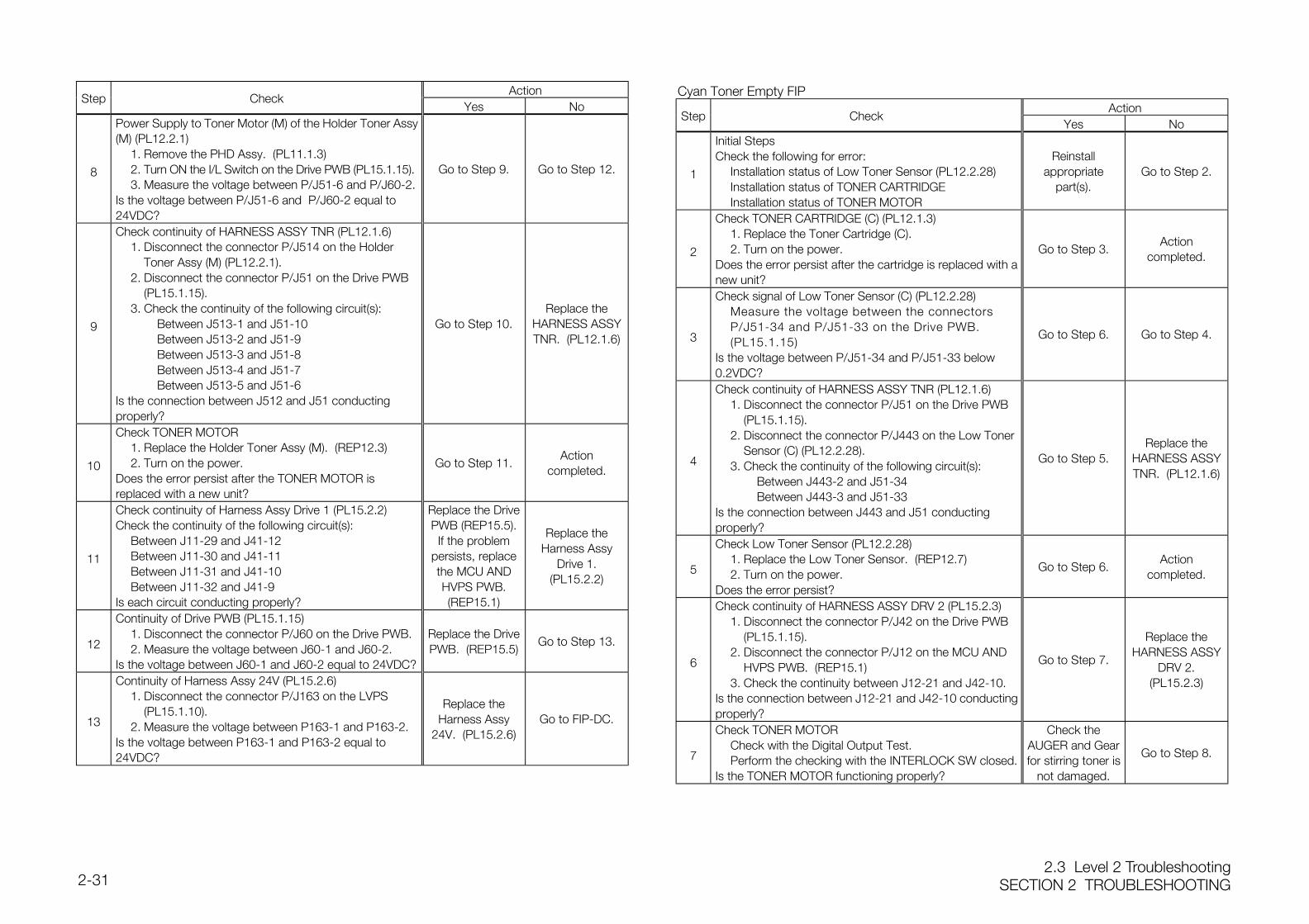
2.3 Level 2 TroubleshootingSECTION 2 TROUBLESHOOTING2-31
ActionStep Check
Yes No
8
Power Supply to Toner Motor (M) of the Holder Toner Assy(M) (PL12.2.1)
1. Remove the PHD Assy. (PL11.1.3)2. Turn ON the I/L Switch on the Drive PWB (PL15.1.15).3. Measure the voltage between P/J51-6 and P/J60-2.
Is the voltage between P/J51-6 and P/J60-2 equal to24VDC?
Go to Step 9. Go to Step 12.
9
Check continuity of HARNESS ASSY TNR (PL12.1.6)1. Disconnect the connector P/J514 on the Holder
Toner Assy (M) (PL12.2.1).2. Disconnect the connector P/J51 on the Drive PWB
(PL15.1.15).3. Check the continuity of the following circuit(s):
Between J513-1 and J51-10Between J513-2 and J51-9Between J513-3 and J51-8Between J513-4 and J51-7Between J513-5 and J51-6
Is the connection between J512 and J51 conductingproperly?
Go to Step 10.Replace the
HARNESS ASSYTNR. (PL12.1.6)
10
Check TONER MOTOR1. Replace the Holder Toner Assy (M). (REP12.3)2. Turn on the power.
Does the error persist after the TONER MOTOR isreplaced with a new unit?
Go to Step 11.Action
completed.
11
Check continuity of Harness Assy Drive 1 (PL15.2.2)Check the continuity of the following circuit(s):
Between J11-29 and J41-12Between J11-30 and J41-11Between J11-31 and J41-10Between J11-32 and J41-9
Is each circuit conducting properly?
Replace the DrivePWB (REP15.5).
If the problempersists, replacethe MCU ANDHVPS PWB.(REP15.1)
Replace theHarness Assy
Drive 1.(PL15.2.2)
12
Continuity of Drive PWB (PL15.1.15)1. Disconnect the connector P/J60 on the Drive PWB.2. Measure the voltage between J60-1 and J60-2.
Is the voltage between J60-1 and J60-2 equal to 24VDC?
Replace the DrivePWB. (REP15.5)
Go to Step 13.
13
Continuity of Harness Assy 24V (PL15.2.6)1. Disconnect the connector P/J163 on the LVPS
(PL15.1.10).2. Measure the voltage between P163-1 and P163-2.
Is the voltage between P163-1 and P163-2 equal to24VDC?
Replace theHarness Assy
24V. (PL15.2.6)Go to FIP-DC.
Cyan Toner Empty FIPAction
Step CheckYes No
1
Initial StepsCheck the following for error:
Installation status of Low Toner Sensor (PL12.2.28)Installation status of TONER CARTRIDGEInstallation status of TONER MOTOR
Reinstallappropriate
part(s).Go to Step 2.
2
Check TONER CARTRIDGE (C) (PL12.1.3)1. Replace the Toner Cartridge (C).2. Turn on the power.
Does the error persist after the cartridge is replaced with anew unit?
Go to Step 3.Action
completed.
3
Check signal of Low Toner Sensor (C) (PL12.2.28)Measure the voltage between the connectors P/J51-34 and P/J51-33 on the Drive PWB. (PL15.1.15)
Is the voltage between P/J51-34 and P/J51-33 below0.2VDC?
Go to Step 6. Go to Step 4.
4
Check continuity of HARNESS ASSY TNR (PL12.1.6)1. Disconnect the connector P/J51 on the Drive PWB
(PL15.1.15).2. Disconnect the connector P/J443 on the Low Toner
Sensor (C) (PL12.2.28).3. Check the continuity of the following circuit(s):
Between J443-2 and J51-34Between J443-3 and J51-33
Is the connection between J443 and J51 conductingproperly?
Go to Step 5.Replace the
HARNESS ASSYTNR. (PL12.1.6)
5
Check Low Toner Sensor (PL12.2.28)1. Replace the Low Toner Sensor. (REP12.7)2. Turn on the power.
Does the error persist?
Go to Step 6.Action
completed.
6
Check continuity of HARNESS ASSY DRV 2 (PL15.2.3)1. Disconnect the connector P/J42 on the Drive PWB
(PL15.1.15).2. Disconnect the connector P/J12 on the MCU AND
HVPS PWB. (REP15.1)3. Check the continuity between J12-21 and J42-10.
Is the connection between J12-21 and J42-10 conductingproperly?
Go to Step 7.
Replace theHARNESS ASSY
DRV 2.(PL15.2.3)
7
Check TONER MOTORCheck with the Digital Output Test.Perform the checking with the INTERLOCK SW closed.
Is the TONER MOTOR functioning properly?
Check theAUGER and Gearfor stirring toner is
not damaged.
Go to Step 8.
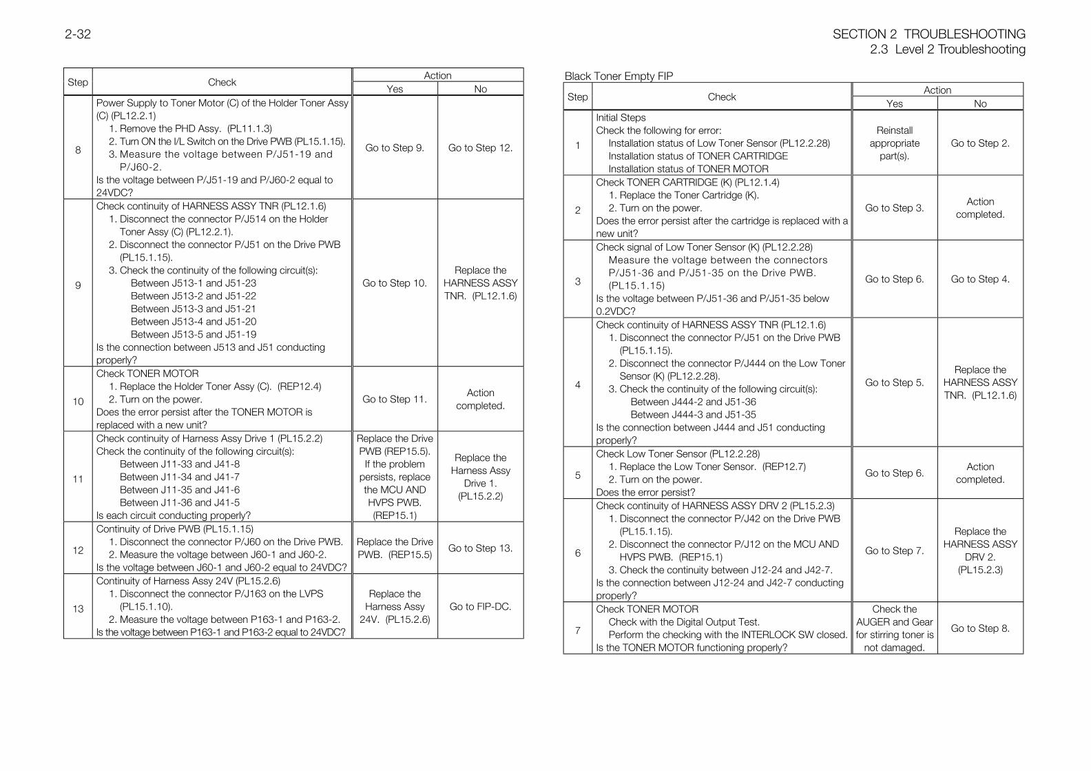
SECTION 2 TROUBLESHOOTING2.3 Level 2 Troubleshooting
2-32
ActionStep Check
Yes No
8
Power Supply to Toner Motor (C) of the Holder Toner Assy(C) (PL12.2.1)
1. Remove the PHD Assy. (PL11.1.3)2. Turn ON the I/L Switch on the Drive PWB (PL15.1.15).3. Measure the voltage between P/J51-19 and
P/J60-2.Is the voltage between P/J51-19 and P/J60-2 equal to24VDC?
Go to Step 9. Go to Step 12.
9
Check continuity of HARNESS ASSY TNR (PL12.1.6)1. Disconnect the connector P/J514 on the Holder
Toner Assy (C) (PL12.2.1).2. Disconnect the connector P/J51 on the Drive PWB
(PL15.1.15).3. Check the continuity of the following circuit(s):
Between J513-1 and J51-23Between J513-2 and J51-22Between J513-3 and J51-21Between J513-4 and J51-20Between J513-5 and J51-19
Is the connection between J513 and J51 conductingproperly?
Go to Step 10.Replace the
HARNESS ASSYTNR. (PL12.1.6)
10
Check TONER MOTOR1. Replace the Holder Toner Assy (C). (REP12.4)2. Turn on the power.
Does the error persist after the TONER MOTOR isreplaced with a new unit?
Go to Step 11.Action
completed.
11
Check continuity of Harness Assy Drive 1 (PL15.2.2)Check the continuity of the following circuit(s):
Between J11-33 and J41-8Between J11-34 and J41-7Between J11-35 and J41-6Between J11-36 and J41-5
Is each circuit conducting properly?
Replace the DrivePWB (REP15.5).
If the problempersists, replacethe MCU ANDHVPS PWB.(REP15.1)
Replace theHarness Assy
Drive 1.(PL15.2.2)
12
Continuity of Drive PWB (PL15.1.15)1. Disconnect the connector P/J60 on the Drive PWB.2. Measure the voltage between J60-1 and J60-2.
Is the voltage between J60-1 and J60-2 equal to 24VDC?
Replace the DrivePWB. (REP15.5)
Go to Step 13.
13
Continuity of Harness Assy 24V (PL15.2.6)1. Disconnect the connector P/J163 on the LVPS
(PL15.1.10).2. Measure the voltage between P163-1 and P163-2.
Is the voltage between P163-1 and P163-2 equal to 24VDC?
Replace theHarness Assy
24V. (PL15.2.6)Go to FIP-DC.
Black Toner Empty FIPAction
Step CheckYes No
1
Initial StepsCheck the following for error:
Installation status of Low Toner Sensor (PL12.2.28)Installation status of TONER CARTRIDGEInstallation status of TONER MOTOR
Reinstallappropriate
part(s).Go to Step 2.
2
Check TONER CARTRIDGE (K) (PL12.1.4)1. Replace the Toner Cartridge (K).2. Turn on the power.
Does the error persist after the cartridge is replaced with anew unit?
Go to Step 3.Action
completed.
3
Check signal of Low Toner Sensor (K) (PL12.2.28)Measure the voltage between the connectors P/J51-36 and P/J51-35 on the Drive PWB. (PL15.1.15)
Is the voltage between P/J51-36 and P/J51-35 below0.2VDC?
Go to Step 6. Go to Step 4.
4
Check continuity of HARNESS ASSY TNR (PL12.1.6)1. Disconnect the connector P/J51 on the Drive PWB
(PL15.1.15).2. Disconnect the connector P/J444 on the Low Toner
Sensor (K) (PL12.2.28).3. Check the continuity of the following circuit(s):
Between J444-2 and J51-36Between J444-3 and J51-35
Is the connection between J444 and J51 conductingproperly?
Go to Step 5.Replace the
HARNESS ASSYTNR. (PL12.1.6)
5
Check Low Toner Sensor (PL12.2.28)1. Replace the Low Toner Sensor. (REP12.7)2. Turn on the power.
Does the error persist?
Go to Step 6.Action
completed.
6
Check continuity of HARNESS ASSY DRV 2 (PL15.2.3)1. Disconnect the connector P/J42 on the Drive PWB
(PL15.1.15).2. Disconnect the connector P/J12 on the MCU AND
HVPS PWB. (REP15.1)3. Check the continuity between J12-24 and J42-7.
Is the connection between J12-24 and J42-7 conductingproperly?
Go to Step 7.
Replace theHARNESS ASSY
DRV 2.(PL15.2.3)
7
Check TONER MOTORCheck with the Digital Output Test.Perform the checking with the INTERLOCK SW closed.
Is the TONER MOTOR functioning properly?
Check theAUGER and Gearfor stirring toner is
not damaged.
Go to Step 8.
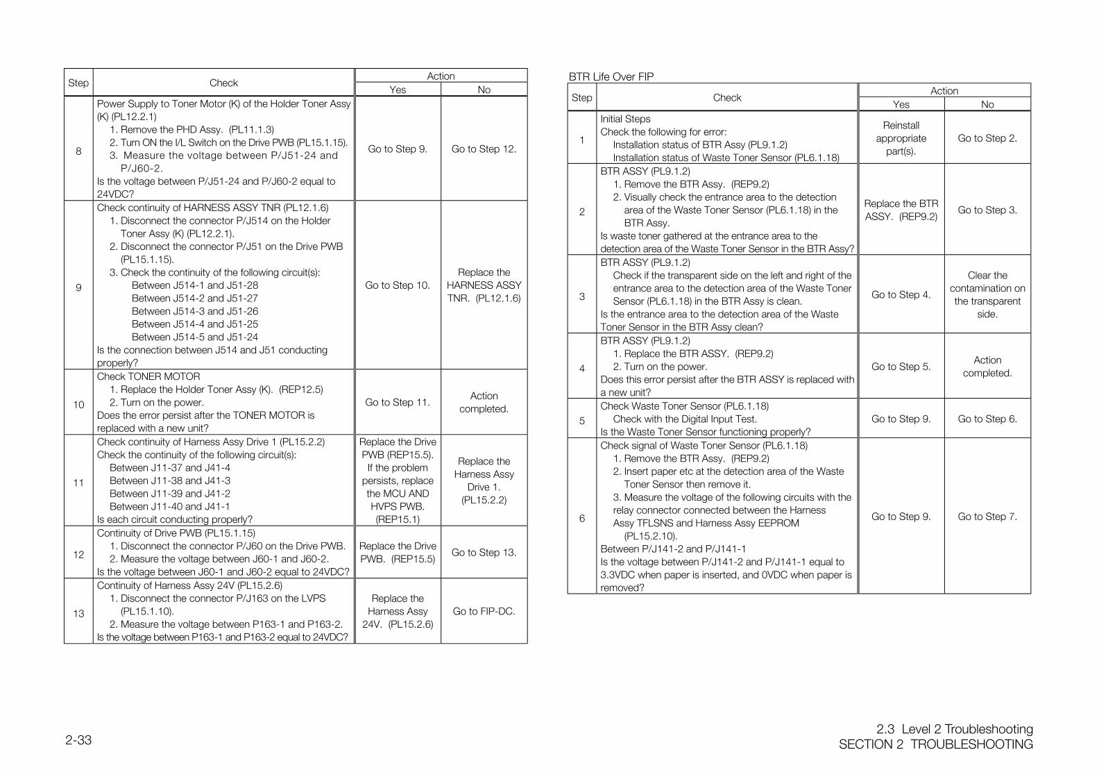
2.3 Level 2 TroubleshootingSECTION 2 TROUBLESHOOTING2-33
ActionStep Check
Yes No
8
Power Supply to Toner Motor (K) of the Holder Toner Assy(K) (PL12.2.1)
1. Remove the PHD Assy. (PL11.1.3)2. Turn ON the I/L Switch on the Drive PWB (PL15.1.15).3. Measure the voltage between P/J51-24 and
P/J60-2.Is the voltage between P/J51-24 and P/J60-2 equal to24VDC?
Go to Step 9. Go to Step 12.
9
Check continuity of HARNESS ASSY TNR (PL12.1.6)1. Disconnect the connector P/J514 on the Holder
Toner Assy (K) (PL12.2.1).2. Disconnect the connector P/J51 on the Drive PWB
(PL15.1.15).3. Check the continuity of the following circuit(s):
Between J514-1 and J51-28Between J514-2 and J51-27Between J514-3 and J51-26Between J514-4 and J51-25Between J514-5 and J51-24
Is the connection between J514 and J51 conductingproperly?
Go to Step 10.Replace the
HARNESS ASSYTNR. (PL12.1.6)
10
Check TONER MOTOR1. Replace the Holder Toner Assy (K). (REP12.5)2. Turn on the power.
Does the error persist after the TONER MOTOR isreplaced with a new unit?
Go to Step 11.Action
completed.
11
Check continuity of Harness Assy Drive 1 (PL15.2.2)Check the continuity of the following circuit(s):
Between J11-37 and J41-4Between J11-38 and J41-3Between J11-39 and J41-2Between J11-40 and J41-1
Is each circuit conducting properly?
Replace the DrivePWB (REP15.5).
If the problempersists, replacethe MCU ANDHVPS PWB.(REP15.1)
Replace theHarness Assy
Drive 1.(PL15.2.2)
12
Continuity of Drive PWB (PL15.1.15)1. Disconnect the connector P/J60 on the Drive PWB.2. Measure the voltage between J60-1 and J60-2.
Is the voltage between J60-1 and J60-2 equal to 24VDC?
Replace the DrivePWB. (REP15.5)
Go to Step 13.
13
Continuity of Harness Assy 24V (PL15.2.6)1. Disconnect the connector P/J163 on the LVPS
(PL15.1.10).2. Measure the voltage between P163-1 and P163-2.
Is the voltage between P163-1 and P163-2 equal to 24VDC?
Replace theHarness Assy
24V. (PL15.2.6)Go to FIP-DC.
BTR Life Over FIPAction
Step CheckYes No
1
Initial StepsCheck the following for error:
Installation status of BTR Assy (PL9.1.2)Installation status of Waste Toner Sensor (PL6.1.18)
Reinstallappropriate
part(s).Go to Step 2.
2
BTR ASSY (PL9.1.2)1. Remove the BTR Assy. (REP9.2)2. Visually check the entrance area to the detection
area of the Waste Toner Sensor (PL6.1.18) in the BTR Assy.
Is waste toner gathered at the entrance area to thedetection area of the Waste Toner Sensor in the BTR Assy?
Replace the BTRASSY. (REP9.2)
Go to Step 3.
3
BTR ASSY (PL9.1.2)Check if the transparent side on the left and right of the entrance area to the detection area of the Waste TonerSensor (PL6.1.18) in the BTR Assy is clean.
Is the entrance area to the detection area of the WasteToner Sensor in the BTR Assy clean?
Go to Step 4.
Clear thecontamination onthe transparent
side.
4
BTR ASSY (PL9.1.2)1. Replace the BTR ASSY. (REP9.2)2. Turn on the power.
Does this error persist after the BTR ASSY is replaced witha new unit?
Go to Step 5.Action
completed.
5Check Waste Toner Sensor (PL6.1.18)
Check with the Digital Input Test.Is the Waste Toner Sensor functioning properly?
Go to Step 9. Go to Step 6.
6
Check signal of Waste Toner Sensor (PL6.1.18)1. Remove the BTR Assy. (REP9.2)2. Insert paper etc at the detection area of the Waste
Toner Sensor then remove it.3. Measure the voltage of the following circuits with the relay connector connected between the Harness Assy TFLSNS and Harness Assy EEPROM
(PL15.2.10).Between P/J141-2 and P/J141-1Is the voltage between P/J141-2 and P/J141-1 equal to3.3VDC when paper is inserted, and 0VDC when paper isremoved?
Go to Step 9. Go to Step 7.
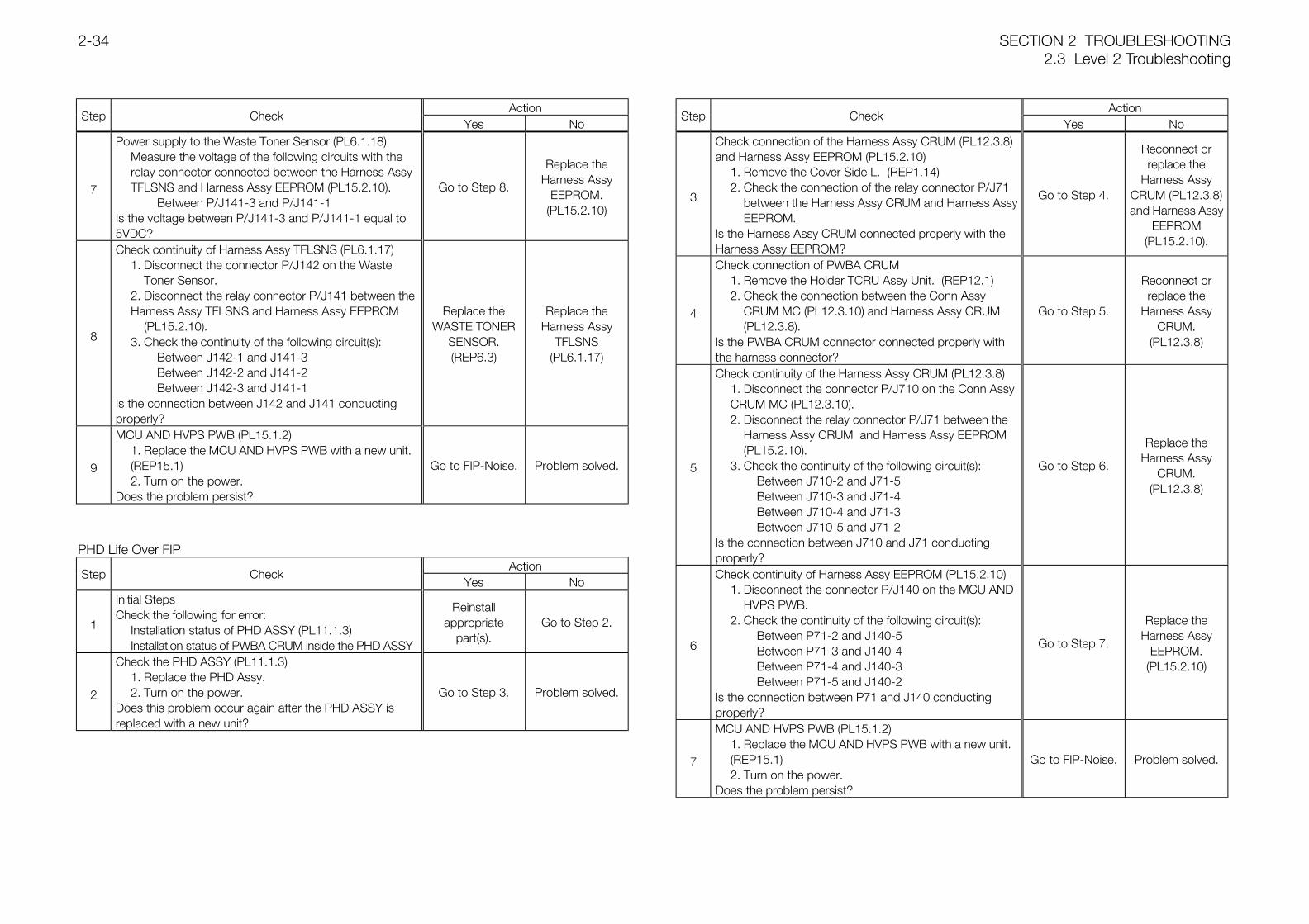
SECTION 2 TROUBLESHOOTING2.3 Level 2 Troubleshooting
2-34
ActionStep Check
Yes No
7
Power supply to the Waste Toner Sensor (PL6.1.18)Measure the voltage of the following circuits with the relay connector connected between the Harness Assy TFLSNS and Harness Assy EEPROM (PL15.2.10).
Between P/J141-3 and P/J141-1Is the voltage between P/J141-3 and P/J141-1 equal to5VDC?
Go to Step 8.
Replace theHarness Assy
EEPROM.(PL15.2.10)
8
Check continuity of Harness Assy TFLSNS (PL6.1.17)1. Disconnect the connector P/J142 on the Waste
Toner Sensor.2. Disconnect the relay connector P/J141 between the Harness Assy TFLSNS and Harness Assy EEPROM
(PL15.2.10).3. Check the continuity of the following circuit(s):
Between J142-1 and J141-3Between J142-2 and J141-2Between J142-3 and J141-1
Is the connection between J142 and J141 conductingproperly?
Replace theWASTE TONER
SENSOR.(REP6.3)
Replace theHarness Assy
TFLSNS(PL6.1.17)
9
MCU AND HVPS PWB (PL15.1.2)1. Replace the MCU AND HVPS PWB with a new unit. (REP15.1)2. Turn on the power.
Does the problem persist?
Go to FIP-Noise. Problem solved.
PHD Life Over FIPAction
Step CheckYes No
1
Initial StepsCheck the following for error:
Installation status of PHD ASSY (PL11.1.3)Installation status of PWBA CRUM inside the PHD ASSY
Reinstallappropriate
part(s).Go to Step 2.
2
Check the PHD ASSY (PL11.1.3)1. Replace the PHD Assy.2. Turn on the power.
Does this problem occur again after the PHD ASSY isreplaced with a new unit?
Go to Step 3. Problem solved.
ActionStep Check
Yes No
3
Check connection of the Harness Assy CRUM (PL12.3.8)and Harness Assy EEPROM (PL15.2.10)
1. Remove the Cover Side L. (REP1.14)2. Check the connection of the relay connector P/J71
between the Harness Assy CRUM and Harness AssyEEPROM.
Is the Harness Assy CRUM connected properly with theHarness Assy EEPROM?
Go to Step 4.
Reconnect orreplace the
Harness AssyCRUM (PL12.3.8)and Harness Assy
EEPROM(PL15.2.10).
4
Check connection of PWBA CRUM1. Remove the Holder TCRU Assy Unit. (REP12.1)2. Check the connection between the Conn Assy
CRUM MC (PL12.3.10) and Harness Assy CRUM (PL12.3.8).
Is the PWBA CRUM connector connected properly withthe harness connector?
Go to Step 5.
Reconnect orreplace the
Harness AssyCRUM.
(PL12.3.8)
5
Check continuity of the Harness Assy CRUM (PL12.3.8)1. Disconnect the connector P/J710 on the Conn Assy CRUM MC (PL12.3.10).2. Disconnect the relay connector P/J71 between the
Harness Assy CRUM and Harness Assy EEPROM (PL15.2.10).
3. Check the continuity of the following circuit(s):Between J710-2 and J71-5Between J710-3 and J71-4Between J710-4 and J71-3Between J710-5 and J71-2
Is the connection between J710 and J71 conductingproperly?
Go to Step 6.
Replace theHarness Assy
CRUM.(PL12.3.8)
6
Check continuity of Harness Assy EEPROM (PL15.2.10)1. Disconnect the connector P/J140 on the MCU AND
HVPS PWB.2. Check the continuity of the following circuit(s):
Between P71-2 and J140-5Between P71-3 and J140-4Between P71-4 and J140-3Between P71-5 and J140-2
Is the connection between P71 and J140 conductingproperly?
Go to Step 7.
Replace theHarness Assy
EEPROM.(PL15.2.10)
7
MCU AND HVPS PWB (PL15.1.2)1. Replace the MCU AND HVPS PWB with a new unit. (REP15.1)2. Turn on the power.
Does the problem persist?
Go to FIP-Noise. Problem solved.
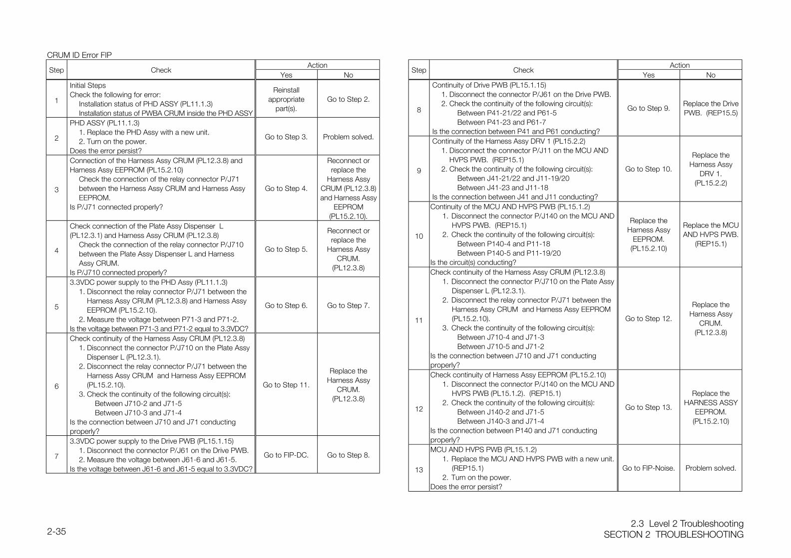
2.3 Level 2 TroubleshootingSECTION 2 TROUBLESHOOTING2-35
CRUM ID Error FIPAction
Step CheckYes No
1
Initial StepsCheck the following for error:
Installation status of PHD ASSY (PL11.1.3)Installation status of PWBA CRUM inside the PHD ASSY
Reinstallappropriate
part(s).Go to Step 2.
2
PHD ASSY (PL11.1.3)1. Replace the PHD Assy with a new unit.2. Turn on the power.
Does the error persist?
Go to Step 3. Problem solved.
3
Connection of the Harness Assy CRUM (PL12.3.8) andHarness Assy EEPROM (PL15.2.10)
Check the connection of the relay connector P/J71 between the Harness Assy CRUM and Harness Assy EEPROM.
Is P/J71 connected properly?
Go to Step 4.
Reconnect orreplace the
Harness AssyCRUM (PL12.3.8)and Harness Assy
EEPROM(PL15.2.10).
4
Check connection of the Plate Assy Dispenser L(PL12.3.1) and Harness Assy CRUM (PL12.3.8)
Check the connection of the relay connector P/J710 between the Plate Assy Dispenser L and Harness Assy CRUM.
Is P/J710 connected properly?
Go to Step 5.
Reconnect orreplace the
Harness AssyCRUM.
(PL12.3.8)
5
3.3VDC power supply to the PHD Assy (PL11.1.3)1. Disconnect the relay connector P/J71 between the
Harness Assy CRUM (PL12.3.8) and Harness Assy EEPROM (PL15.2.10).
2. Measure the voltage between P71-3 and P71-2.Is the voltage between P71-3 and P71-2 equal to 3.3VDC?
Go to Step 6. Go to Step 7.
6
Check continuity of the Harness Assy CRUM (PL12.3.8)1. Disconnect the connector P/J710 on the Plate Assy
Dispenser L (PL12.3.1).2. Disconnect the relay connector P/J71 between the
Harness Assy CRUM and Harness Assy EEPROM (PL15.2.10).
3. Check the continuity of the following circuit(s):Between J710-2 and J71-5Between J710-3 and J71-4
Is the connection between J710 and J71 conductingproperly?
Go to Step 11.
Replace theHarness Assy
CRUM.(PL12.3.8)
7
3.3VDC power supply to the Drive PWB (PL15.1.15)1. Disconnect the connector P/J61 on the Drive PWB.2. Measure the voltage between J61-6 and J61-5.
Is the voltage between J61-6 and J61-5 equal to 3.3VDC?
Go to FIP-DC. Go to Step 8.
ActionStep Check
Yes No
8
Continuity of Drive PWB (PL15.1.15)1. Disconnect the connector P/J61 on the Drive PWB.2. Check the continuity of the following circuit(s):
Between P41-21/22 and P61-5Between P41-23 and P61-7
Is the connection between P41 and P61 conducting?
Go to Step 9.Replace the DrivePWB. (REP15.5)
9
Continuity of the Harness Assy DRV 1 (PL15.2.2)1. Disconnect the connector P/J11 on the MCU AND
HVPS PWB. (REP15.1)2. Check the continuity of the following circuit(s):
Between J41-21/22 and J11-19/20Between J41-23 and J11-18
Is the connection between J41 and J11 conducting?
Go to Step 10.
Replace theHarness Assy
DRV 1.(PL15.2.2)
10
Continuity of the MCU AND HVPS PWB (PL15.1.2)1. Disconnect the connector P/J140 on the MCU AND
HVPS PWB. (REP15.1)2. Check the continuity of the following circuit(s):
Between P140-4 and P11-18Between P140-5 and P11-19/20
Is the circuit(s) conducting?
Replace theHarness Assy
EEPROM.(PL15.2.10)
Replace the MCUAND HVPS PWB.
(REP15.1)
11
Check continuity of the Harness Assy CRUM (PL12.3.8)1. Disconnect the connector P/J710 on the Plate Assy
Dispenser L (PL12.3.1).2. Disconnect the relay connector P/J71 between the
Harness Assy CRUM and Harness Assy EEPROM(PL15.2.10).
3. Check the continuity of the following circuit(s):Between J710-4 and J71-3Between J710-5 and J71-2
Is the connection between J710 and J71 conductingproperly?
Go to Step 12.
Replace theHarness Assy
CRUM.(PL12.3.8)
12
Check continuity of Harness Assy EEPROM (PL15.2.10)1. Disconnect the connector P/J140 on the MCU AND
HVPS PWB (PL15.1.2). (REP15.1)2. Check the continuity of the following circuit(s):
Between J140-2 and J71-5Between J140-3 and J71-4
Is the connection between P140 and J71 conductingproperly?
Go to Step 13.
Replace theHARNESS ASSY
EEPROM.(PL15.2.10)
13
MCU AND HVPS PWB (PL15.1.2)1. Replace the MCU AND HVPS PWB with a new unit.
(REP15.1)2. Turn on the power.
Does the error persist?
Go to FIP-Noise. Problem solved.
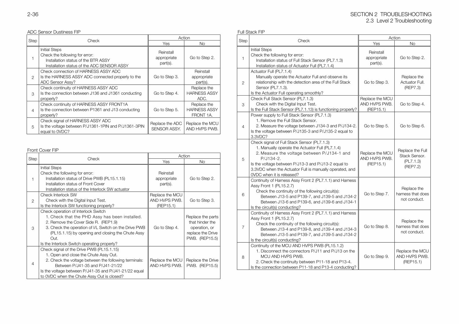
SECTION 2 TROUBLESHOOTING2.3 Level 2 Troubleshooting
2-36
ADC Sensor Dustiness FIPAction
Step CheckYes No
1
Initial StepsCheck the following for error:
Installation status of the BTR ASSYInstallation status of the ADC SENSOR ASSY
Reinstallappropriate
part(s).Go to Step 2.
2Check connection of HARNESS ASSY ADCIs the HARNESS ASSY ADC connected properly to theADC Sensor Assy?
Go to Step 3.Reinstall
appropriatepart(s).
3Check continuity of HARNESS ASSY ADCIs the connection between J136 and J1361 conductingproperly?
Go to Step 4.Replace the
HARNESS ASSYADC.
4Check continuity of HARNESS ASSY FRONT1AIs the connection between P1361 and J13 conductingproperly?
Go to Step 5.Replace the
HARNESS ASSYFRONT 1A.
5Check signal of HARNESS ASSY ADCIs the voltage between P/J1361-1PIN and P/J1361-3PINequal to 0VDC?
Replace the ADCSENSOR ASSY.
Replace the MCUAND HVPS PWB.
Front Cover FIPAction
Step CheckYes No
1
Initial StepsCheck the following for error:
Installation status of Drive PWB (PL15.1.15)Installation status of Front CoverInstallation status of the Interlock SW actuator
Reinstallappropriate
part(s).Go to Step 2.
2Check Interlock SW
Check with the Digital Input Test.Is the Interlock SW functioning properly?
Replace the MCUAND HVPS PWB.
(REP15.1)Go to Step 3.
3
Check operation of Interlock Switch1. Check that the PHD Assy has been installed.2. Remove the Cover Side R. (REP1.9)3. Check the operation of I/L Switch on the Drive PWB
(PL15.1.15) by opening and closing the Chute Assy Out.
Is the Interlock Switch operating properly?
Go to Step 4.
Replace the partsthat hinder theoperation, or
replace the DrivePWB. (REP15.5)
4
Check signal of the Drive PWB (PL15.1.15)1. Open and close the Chute Assy Out.2. Check the voltage between the following terminals:
Between P/J41-35 and P/J41-21/22Is the voltage between P/J41-35 and P/J41-21/22 equalto 0VDC when the Chute Assy Out is closed?
Replace the MCUAND HVPS PWB.
Replace the DrivePWB. (REP15.5)
Full Stack FIPAction
Step CheckYes No
1
Initial StepsCheck the following for error:
Installation status of Full Stack Sensor (PL7.1.3)Installation status of Actuator Full (PL7.1.4)
Reinstallappropriate
part(s).Go to Step 2.
2
Actuator Full (PL7.1.4)Manually operate the Actuator Full and observe its relationship with the detection area of the Full Stack Sensor (PL7.1.3).
Is the Actuator Full operating smoothly?
Go to Step 3.Replace theActuator Full.
(REP7.3)
3Check Full Stack Sensor (PL7.1.3)
Check with the Digital Input Test.Is the Full Stack Sensor (PL7.1.13) is functioning properly?
Replace the MCUAND HVPS PWB.
(REP15.1)Go to Step 4.
4
Power supply to Full Stack Sensor (PL7.1.3)1. Remove the Full Stack Sensor.2. Measure the voltage between J134-3 and P/J134-2.
Is the voltage between P/J135-3 and P/J135-2 equal to3.3VDC?
Go to Step 5. Go to Step 6.
5
Check signal of Full Stack Sensor (PL7.1.3)1. Manually operate the Actuator Full (PL7.1.4)2. Measure the voltage between P/J134-1 and
P/J134-2.Is the voltage between P/J13-3 and P/J13-2 equal to3.3VDC when the Actuator Full is manually operated, and0VDC when it is released?
Replace the MCUAND HVPS PWB.
(REP15.1)
Replace the FullStack Sensor.
(PL7.1.3)(REP7.2)
6
Continuity of Harness Assy Front 2 (PL7.1.1) and HarnessAssy Front 1 (PL15.2.7)
Check the continuity of the following circuit(s):Between J13-5 and P139-7, and J139-5 and J134-2Between J13-6 and P139-6, and J139-6 and J134-1
Is the circuit(s) conducting?
Go to Step 7.Replace the
harness that doesnot conduct.
7
Continuity of Harness Assy Front 2 (PL7.1.1) and HarnessAssy Front 1 (PL15.2.7)
Check the continuity of the following circuit(s):Between J13-4 and P139-8, and J139-4 and J134-3Between J13-5 and P139-7, and J139-5 and J134-2
Is the circuit(s) conducting?
Go to Step 8.Replace the
harness that doesnot conduct.
8
Continuity of the MCU AND HVPS PWB (PL15.1.2)1. Disconnect the connectors P/J11 and P/J13 on the
MCU AND HVPS PWB.2. Check the continuity between P11-18 and P13-4.
Is the connection between P11-18 and P13-4 conducting?
Go to Step 9.Replace the MCUAND HVPS PWB.
(REP15.1)
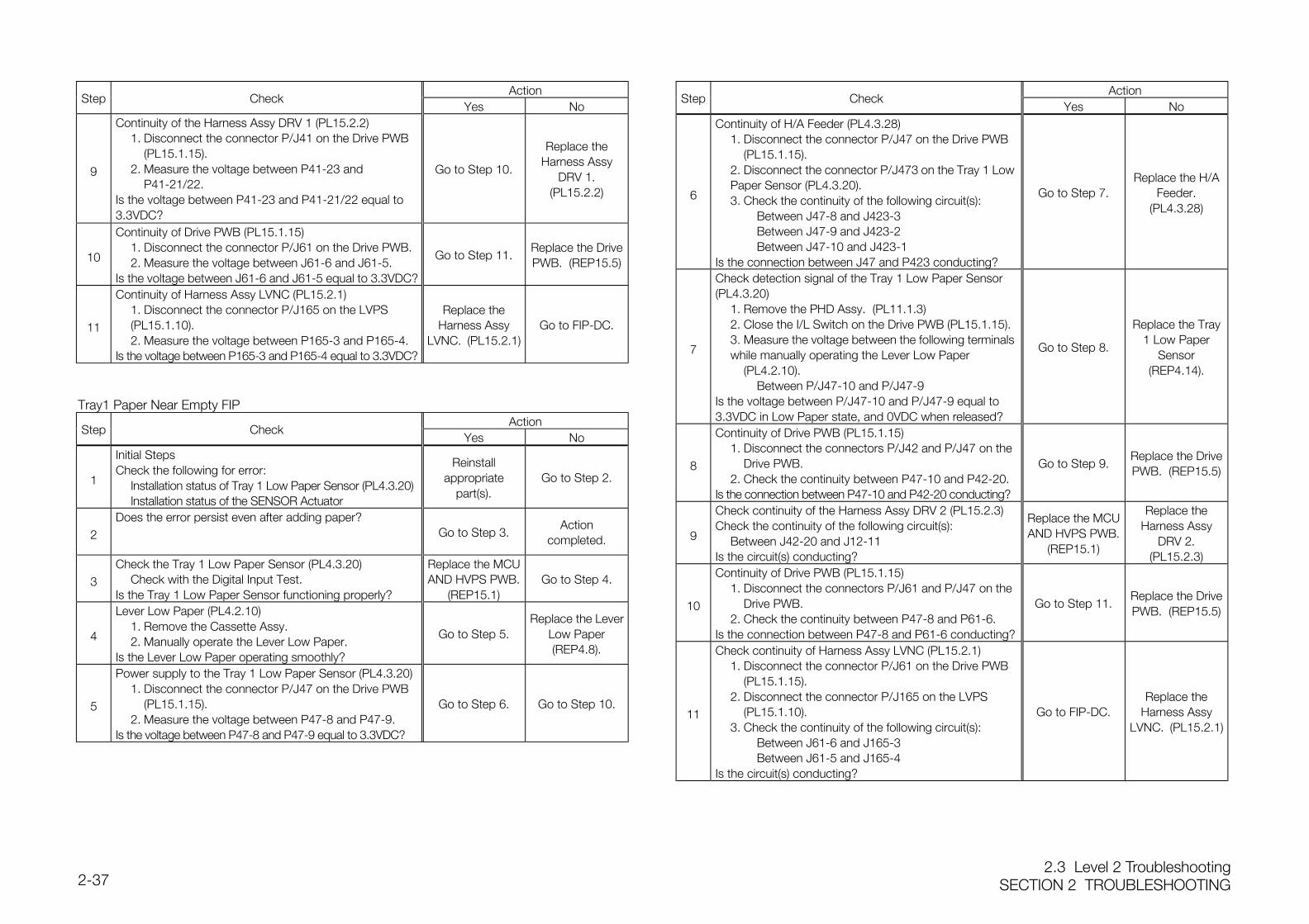
2.3 Level 2 TroubleshootingSECTION 2 TROUBLESHOOTING2-37
ActionStep Check
Yes No
9
Continuity of the Harness Assy DRV 1 (PL15.2.2)1. Disconnect the connector P/J41 on the Drive PWB
(PL15.1.15).2. Measure the voltage between P41-23 and
P41-21/22.Is the voltage between P41-23 and P41-21/22 equal to3.3VDC?
Go to Step 10.
Replace theHarness Assy
DRV 1.(PL15.2.2)
10
Continuity of Drive PWB (PL15.1.15)1. Disconnect the connector P/J61 on the Drive PWB.2. Measure the voltage between J61-6 and J61-5.
Is the voltage between J61-6 and J61-5 equal to 3.3VDC?
Go to Step 11.Replace the DrivePWB. (REP15.5)
11
Continuity of Harness Assy LVNC (PL15.2.1)1. Disconnect the connector P/J165 on the LVPS (PL15.1.10).2. Measure the voltage between P165-3 and P165-4.
Is the voltage between P165-3 and P165-4 equal to 3.3VDC?
Replace theHarness Assy
LVNC. (PL15.2.1)Go to FIP-DC.
Tray1 Paper Near Empty FIPAction
Step CheckYes No
1
Initial StepsCheck the following for error:
Installation status of Tray 1 Low Paper Sensor (PL4.3.20)Installation status of the SENSOR Actuator
Reinstallappropriate
part(s).Go to Step 2.
2Does the error persist even after adding paper?
Go to Step 3.Action
completed.
3Check the Tray 1 Low Paper Sensor (PL4.3.20)
Check with the Digital Input Test.Is the Tray 1 Low Paper Sensor functioning properly?
Replace the MCUAND HVPS PWB.
(REP15.1)Go to Step 4.
4
Lever Low Paper (PL4.2.10)1. Remove the Cassette Assy.2. Manually operate the Lever Low Paper.
Is the Lever Low Paper operating smoothly?
Go to Step 5.Replace the Lever
Low Paper(REP4.8).
5
Power supply to the Tray 1 Low Paper Sensor (PL4.3.20)1. Disconnect the connector P/J47 on the Drive PWB
(PL15.1.15).2. Measure the voltage between P47-8 and P47-9.
Is the voltage between P47-8 and P47-9 equal to 3.3VDC?
Go to Step 6. Go to Step 10.
ActionStep Check
Yes No
6
Continuity of H/A Feeder (PL4.3.28)1. Disconnect the connector P/J47 on the Drive PWB
(PL15.1.15).2. Disconnect the connector P/J473 on the Tray 1 Low Paper Sensor (PL4.3.20).3. Check the continuity of the following circuit(s):
Between J47-8 and J423-3Between J47-9 and J423-2Between J47-10 and J423-1
Is the connection between J47 and P423 conducting?
Go to Step 7.Replace the H/A
Feeder.(PL4.3.28)
7
Check detection signal of the Tray 1 Low Paper Sensor(PL4.3.20)
1. Remove the PHD Assy. (PL11.1.3)2. Close the I/L Switch on the Drive PWB (PL15.1.15).3. Measure the voltage between the following terminals while manually operating the Lever Low Paper
(PL4.2.10).Between P/J47-10 and P/J47-9
Is the voltage between P/J47-10 and P/J47-9 equal to3.3VDC in Low Paper state, and 0VDC when released?
Go to Step 8.
Replace the Tray1 Low Paper
Sensor(REP4.14).
8
Continuity of Drive PWB (PL15.1.15)1. Disconnect the connectors P/J42 and P/J47 on the
Drive PWB.2. Check the continuity between P47-10 and P42-20.
Is the connection between P47-10 and P42-20 conducting?
Go to Step 9.Replace the DrivePWB. (REP15.5)
9
Check continuity of the Harness Assy DRV 2 (PL15.2.3)Check the continuity of the following circuit(s):
Between J42-20 and J12-11Is the circuit(s) conducting?
Replace the MCUAND HVPS PWB.
(REP15.1)
Replace theHarness Assy
DRV 2.(PL15.2.3)
10
Continuity of Drive PWB (PL15.1.15)1. Disconnect the connectors P/J61 and P/J47 on the
Drive PWB.2. Check the continuity between P47-8 and P61-6.
Is the connection between P47-8 and P61-6 conducting?
Go to Step 11.Replace the DrivePWB. (REP15.5)
11
Check continuity of Harness Assy LVNC (PL15.2.1)1. Disconnect the connector P/J61 on the Drive PWB
(PL15.1.15).2. Disconnect the connector P/J165 on the LVPS
(PL15.1.10).3. Check the continuity of the following circuit(s):
Between J61-6 and J165-3Between J61-5 and J165-4
Is the circuit(s) conducting?
Go to FIP-DC.Replace the
Harness AssyLVNC. (PL15.2.1)
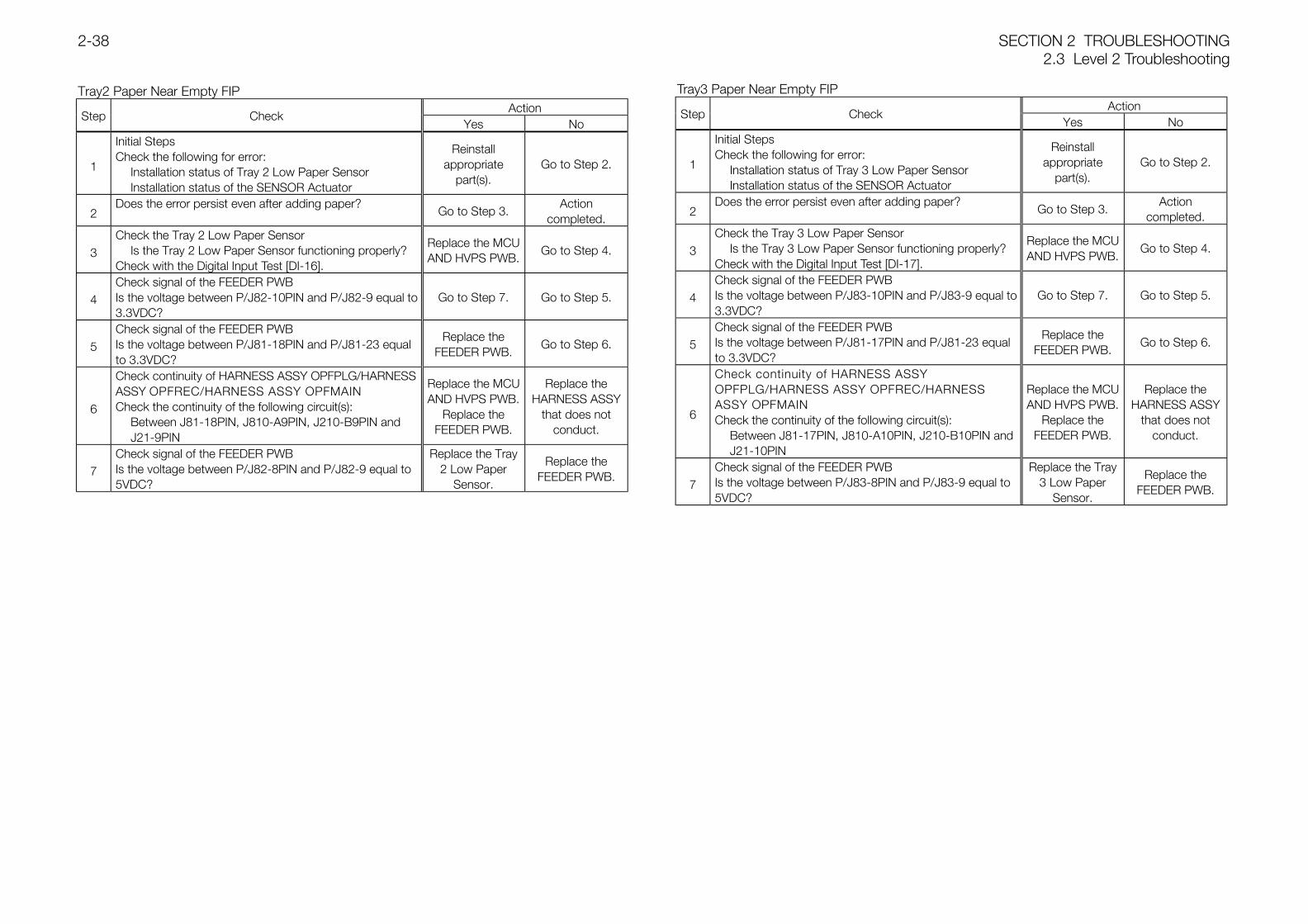
SECTION 2 TROUBLESHOOTING2.3 Level 2 Troubleshooting
2-38
Tray2 Paper Near Empty FIPAction
Step CheckYes No
1
Initial StepsCheck the following for error:
Installation status of Tray 2 Low Paper SensorInstallation status of the SENSOR Actuator
Reinstallappropriate
part(s).Go to Step 2.
2Does the error persist even after adding paper?
Go to Step 3.Action
completed.
3Check the Tray 2 Low Paper Sensor
Is the Tray 2 Low Paper Sensor functioning properly?Check with the Digital Input Test [DI-16].
Replace the MCUAND HVPS PWB.
Go to Step 4.
4Check signal of the FEEDER PWBIs the voltage between P/J82-10PIN and P/J82-9 equal to3.3VDC?
Go to Step 7. Go to Step 5.
5Check signal of the FEEDER PWBIs the voltage between P/J81-18PIN and P/J81-23 equalto 3.3VDC?
Replace theFEEDER PWB.
Go to Step 6.
6
Check continuity of HARNESS ASSY OPFPLG/HARNESSASSY OPFREC/HARNESS ASSY OPFMAINCheck the continuity of the following circuit(s):
Between J81-18PIN, J810-A9PIN, J210-B9PIN and J21-9PIN
Replace the MCUAND HVPS PWB.
Replace theFEEDER PWB.
Replace theHARNESS ASSY
that does notconduct.
7Check signal of the FEEDER PWBIs the voltage between P/J82-8PIN and P/J82-9 equal to5VDC?
Replace the Tray2 Low Paper
Sensor.
Replace theFEEDER PWB.
Tray3 Paper Near Empty FIPAction
Step CheckYes No
1
Initial StepsCheck the following for error:
Installation status of Tray 3 Low Paper SensorInstallation status of the SENSOR Actuator
Reinstallappropriate
part(s).Go to Step 2.
2Does the error persist even after adding paper?
Go to Step 3.Action
completed.
3Check the Tray 3 Low Paper Sensor
Is the Tray 3 Low Paper Sensor functioning properly?Check with the Digital Input Test [DI-17].
Replace the MCUAND HVPS PWB.
Go to Step 4.
4Check signal of the FEEDER PWBIs the voltage between P/J83-10PIN and P/J83-9 equal to3.3VDC?
Go to Step 7. Go to Step 5.
5Check signal of the FEEDER PWBIs the voltage between P/J81-17PIN and P/J81-23 equalto 3.3VDC?
Replace theFEEDER PWB.
Go to Step 6.
6
Check continuity of HARNESS ASSYOPFPLG/HARNESS ASSY OPFREC/HARNESSASSY OPFMAINCheck the continuity of the following circuit(s):
Between J81-17PIN, J810-A10PIN, J210-B10PIN and J21-10PIN
Replace the MCUAND HVPS PWB.
Replace theFEEDER PWB.
Replace theHARNESS ASSY
that does notconduct.
7Check signal of the FEEDER PWBIs the voltage between P/J83-8PIN and P/J83-9 equal to5VDC?
Replace the Tray3 Low Paper
Sensor.
Replace theFEEDER PWB.
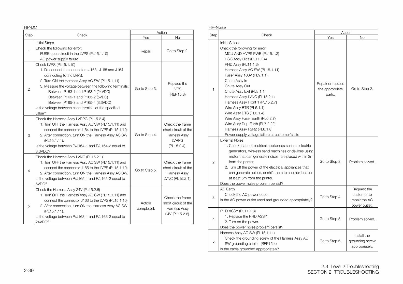
2.3 Level 2 TroubleshootingSECTION 2 TROUBLESHOOTING2-39
FIP-DCAction
Step CheckYes No
1
Initial StepsCheck the following for error:
FUSE open circuit in the LVPS (PL15.1.10)AC power supply failure
Repair Go to Step 2.
2
Check LVPS (PL15.1.10)1. Disconnect the connectors J163,J165 and J164
connecting to the LVPS.2. Turn ON the Harness Assy AC SW (PL15.1.11).3. Measure the voltage between the following terminals:
Between P163-1 and P163-2 (24VDC)Between P165-1 and P165-2 (5VDC)Between P165-3 and P165-4 (3.3VDC)
Is the voltage between each terminal at the specifiedvalue?
Go to Step 3.Replace the
LVPS.(REP15.3)
3
Check the Harness Assy LVRPG (PL15.2.4)1. Turn OFF the Harness Assy AC SW (PL15.1.11) and
connect the connector J164 to the LVPS (PL15.1.10).2. After connection, turn ON the Harness Assy AC SW
(PL15.1.11).Is the voltage between P/J164-1 and P/J164-2 equal to3.3VDC?
Go to Step 4.
Check the frameshort circuit of the
Harness AssyLVRPG
(PL15.2.4).
4
Check the Harness Assy LVNC (PL15.2.1)1. Turn OFF the Harness Assy AC SW (PL15.1.11) and
connect the connector J165 to the LVPS (PL15.1.10).2. After connection, turn ON the Harness Assy AC SW.
Is the voltage between P/J165-1 and P/J165-2 equal to5VDC?
Go to Step 5.
Check the frameshort circuit of the
Harness AssyLVNC (PL15.2.1).
5
Check the Harness Assy 24V (PL15.2.6)1. Turn OFF the Harness Assy AC SW (PL15.1.11) and
connect the connector J163 to the LVPS (PL15.1.10).2. After connection, turn ON the Harness Assy AC SW
(PL15.1.11).Is the voltage between P/J163-1 and P/J163-2 equal to24VDC?
Actioncompleted.
Check the frameshort circuit of the
Harness Assy24V (PL15.2.6).
FIP-NoiseAction
Step CheckYes No
1
Initial StepsCheck the following for error:
MCU AND HVPS PWB (PL15.1.2)HSG Assy Bias (PL11.1.4)PHD Assy (PL11.1.3)Harness Assy AC SW (PL15.1.11)Fuser Assy 100V (PL9.1.1)Chute Assy InChute Assy OutChute Assy Exit (PL8.1.1)Harness Assy LVNC (PL15.2.1)Harness Assy Front 1 (PL15.2.7)Wire Assy BTR (PL6.1.1)Wire Assy DTS (PL6.1.4)Wire Assy Fuser Earth (PL6.2.7)Wire Assy Dup Earth (PL7.2.22)Harness Assy FSR2 (PL6.1.8)Power supply voltage failure at customer's site
Repair or replacethe appropriate
parts.
Go to Step 2.
2
External Noise1. Check that no electrical appliances such as electric
generators, wireless send machines or devices usingmotor that can generate noises, are placed within 3mfrom the printer.
2. Turn off the power of the electrical appliances that can generate noises, or shift them to another locationat least 6m from the printer.
Does the power noise problem persist?
Go to Step 3. Problem solved.
3
AC EarthCheck the AC power outlet.
Is the AC power outlet used and grounded appropriately?Go to Step 4.
Request thecustomer torepair the ACpower outlet.
4
PHD ASSY (PL11.1.3)1. Replace the PHD ASSY.2. Turn on the power.
Does the power noise problem persist?
Go to Step 5. Problem solved.
5
Harness Assy AC SW (PL15.1.11)Check the grounding screw of the Harness Assy AC SW grounding cable. (REP15.4)
Is the cable grounded appropriately?
Go to Step 6.Install the
grounding screwappropriately.
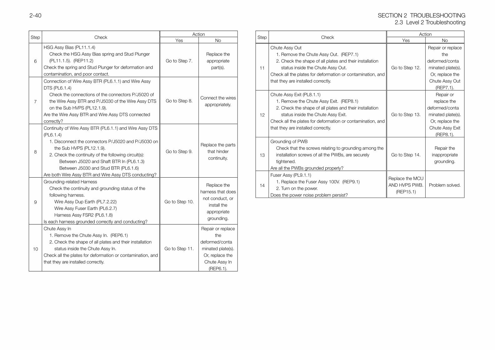
SECTION 2 TROUBLESHOOTING2.3 Level 2 Troubleshooting
2-40
ActionStep Check
Yes No
6
HSG Assy Bias (PL11.1.4)Check the HSG Assy Bias spring and Stud Plunger (PL11.1.5). (REP11.2)
Check the spring and Stud Plunger for deformation andcontamination, and poor contact.
Go to Step 7.Replace theappropriate
part(s).
7
Connection of Wire Assy BTR (PL6.1.1) and Wire AssyDTS (PL6.1.4)
Check the connections of the connectors P/J5020 of the Wire Assy BTR and P/J5030 of the Wire Assy DTS on the Sub HVPS (PL12.1.9).
Are the Wire Assy BTR and Wire Assy DTS connectedcorrectly?
Go to Step 8.Connect the wires
appropriately.
8
Continuity of Wire Assy BTR (PL6.1.1) and Wire Assy DTS(PL6.1.4)
1. Disconnect the connectors P/J5020 and P/J5030 onthe Sub HVPS (PL12.1.9).
2. Check the continuity of the following circuit(s):Between J5020 and Shaft BTR In (PL6.1.3)Between J5030 and Stud BTR (PL6.1.6)
Are both Wire Assy BTR and Wire Assy DTS conducting?
Go to Step 9.Replace the parts
that hindercontinuity.
9
Grounding-related HarnessCheck the continuity and grounding status of the following harness.
Wire Assy Dup Earth (PL7.2.22)Wire Assy Fuser Earth (PL6.2.7)Harness Assy FSR2 (PL6.1.8)
Is each harness grounded correctly and conducting?
Go to Step 10.
Replace theharness that doesnot conduct, or
install theappropriategrounding.
10
Chute Assy In1. Remove the Chute Assy In. (REP6.1)2. Check the shape of all plates and their installation
status inside the Chute Assy In.Check all the plates for deformation or contamination, andthat they are installed correctly.
Go to Step 11.
Repair or replacethe
deformed/contaminated plate(s).Or, replace theChute Assy In
(REP6.1).
ActionStep Check
Yes No
11
Chute Assy Out1. Remove the Chute Assy Out. (REP7.1)2. Check the shape of all plates and their installation
status inside the Chute Assy Out.Check all the plates for deformation or contamination, andthat they are installed correctly.
Go to Step 12.
Repair or replacethe
deformed/contaminated plate(s).Or, replace theChute Assy Out
(REP7.1).
12
Chute Assy Exit (PL8.1.1)1. Remove the Chute Assy Exit. (REP8.1)2. Check the shape of all plates and their installation
status inside the Chute Assy Exit.Check all the plates for deformation or contamination, andthat they are installed correctly.
Go to Step 13.
Repair orreplace the
deformed/contaminated plate(s).Or, replace theChute Assy Exit
(REP8.1).
13
Grounding of PWBCheck that the screws relating to grounding among the installation screws of all the PWBs, are securely tightened.
Are all the PWBs grounded properly?
Go to Step 14.Repair the
inappropriategrounding.
14
Fuser Assy (PL9.1.1)1. Replace the Fuser Assy 100V. (REP9.1)2. Turn on the power.
Does the power noise problem persist?
Replace the MCUAND HVPS PWB.
(REP15.1)Problem solved.
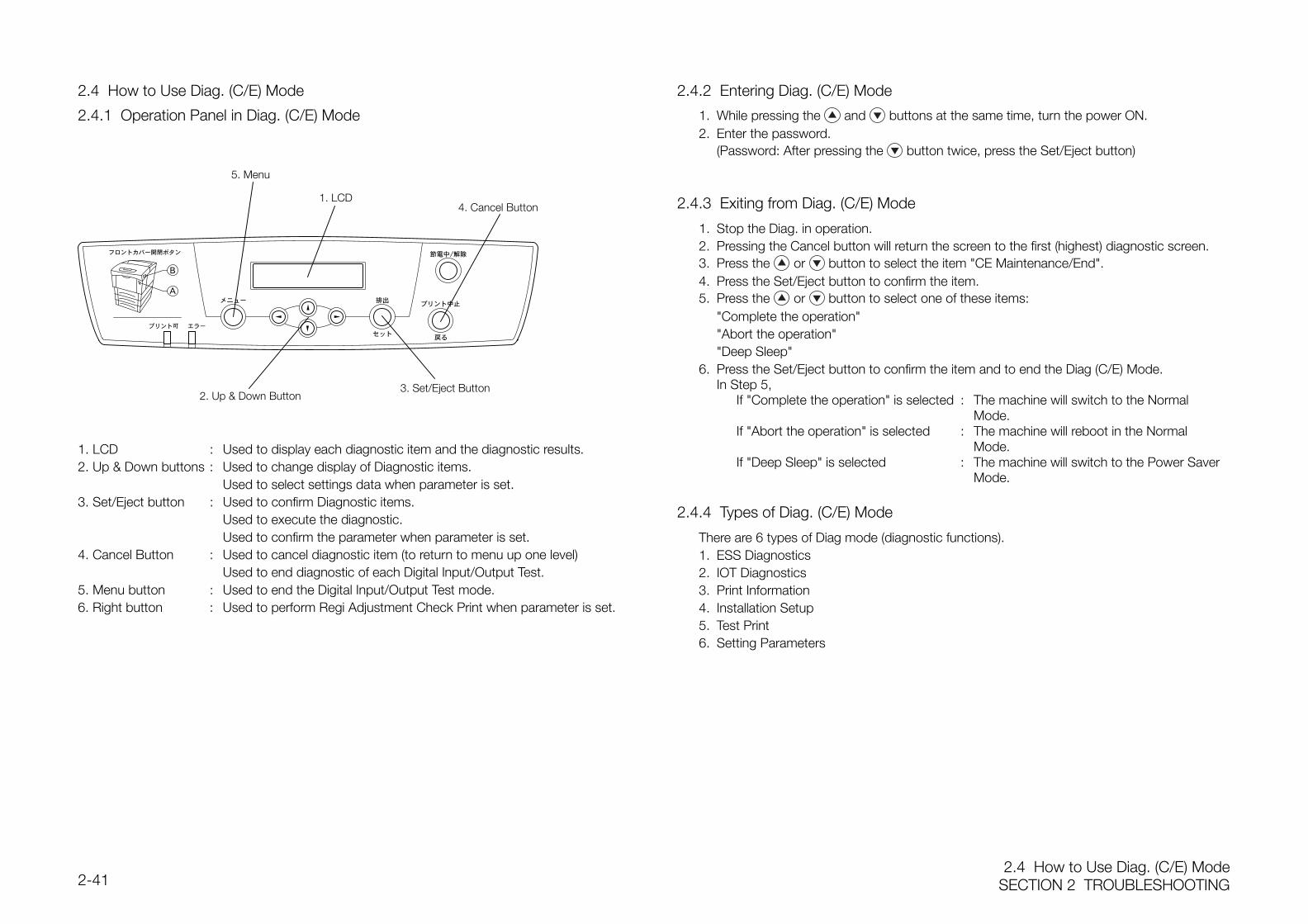
2.4 How to Use Diag. (C/E) ModeSECTION 2 TROUBLESHOOTING2-41
2.4 How to Use Diag. (C/E) Mode
2.4.1 Operation Panel in Diag. (C/E) Mode
1. LCD : Used to display each diagnostic item and the diagnostic results.2. Up & Down buttons : Used to change display of Diagnostic items.
Used to select settings data when parameter is set.3. Set/Eject button : Used to confirm Diagnostic items.
Used to execute the diagnostic.Used to confirm the parameter when parameter is set.
4. Cancel Button : Used to cancel diagnostic item (to return to menu up one level)Used to end diagnostic of each Digital Input/Output Test.
5. Menu button : Used to end the Digital Input/Output Test mode.6. Right button : Used to perform Regi Adjustment Check Print when parameter is set.
2.4.2 Entering Diag. (C/E) Mode
1. While pressing the and buttons at the same time, turn the power ON.2. Enter the password.
(Password: After pressing the button twice, press the Set/Eject button)
2.4.3 Exiting from Diag. (C/E) Mode
1. Stop the Diag. in operation.2. Pressing the Cancel button will return the screen to the first (highest) diagnostic screen.3. Press the or button to select the item "CE Maintenance/End".4. Press the Set/Eject button to confirm the item.5. Press the or button to select one of these items:
"Complete the operation""Abort the operation""Deep Sleep"
6. Press the Set/Eject button to confirm the item and to end the Diag (C/E) Mode.In Step 5,
If "Complete the operation" is selected : The machine will switch to the Normal Mode.
If "Abort the operation" is selected : The machine will reboot in the Normal Mode.
If "Deep Sleep" is selected : The machine will switch to the Power Saver Mode.
2.4.4 Types of Diag. (C/E) Mode
There are 6 types of Diag mode (diagnostic functions).1. ESS Diagnostics2. IOT Diagnostics3. Print Information4. Installation Setup5. Test Print6. Setting Parameters
5. Menu
1. LCD4. Cancel Button
3. Set/Eject Button2. Up & Down Button
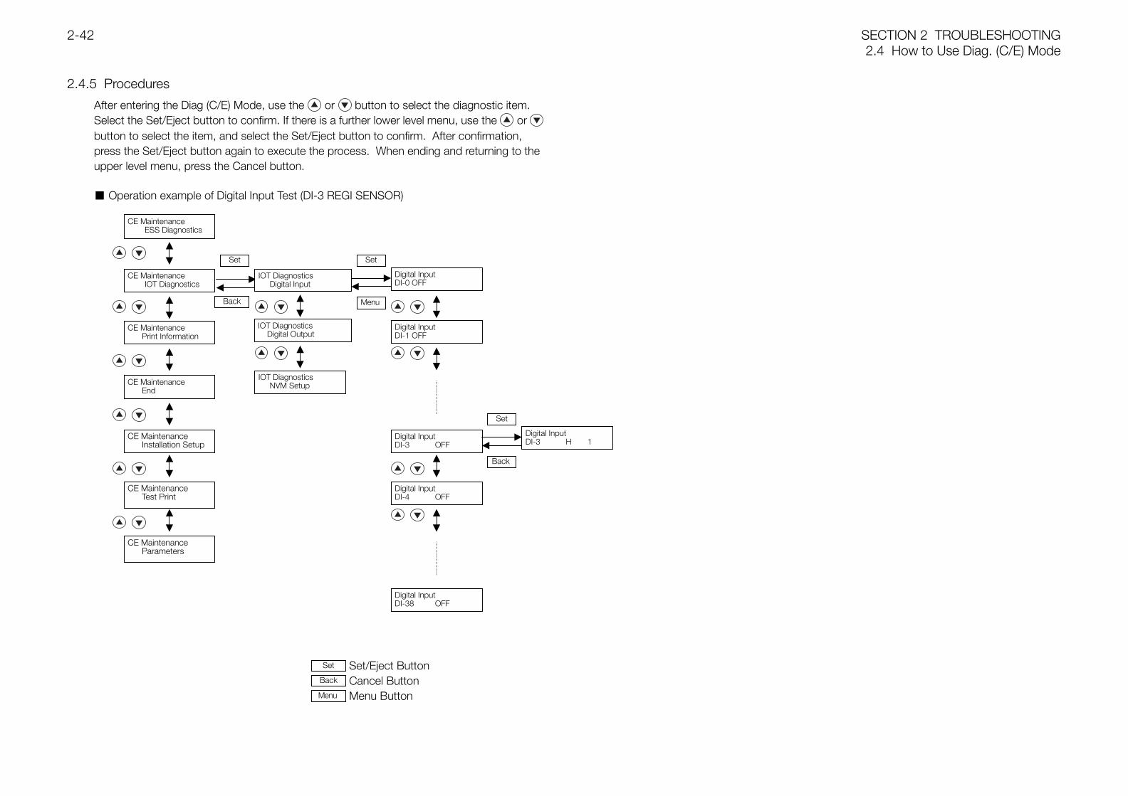
SECTION 2 TROUBLESHOOTING2.4 How to Use Diag. (C/E) Mode
2-42
2.4.5 Procedures
After entering the Diag (C/E) Mode, use the or button to select the diagnostic item.Select the Set/Eject button to confirm. If there is a further lower level menu, use the or button to select the item, and select the Set/Eject button to confirm. After confirmation,press the Set/Eject button again to execute the process. When ending and returning to theupper level menu, press the Cancel button.
Operation example of Digital Input Test (DI-3 REGI SENSOR)
Set/Eject ButtonCancel ButtonMenu Button
CE MaintenanceESS Diagnostics
CE MaintenanceIOT Diagnostics
CE MaintenancePrint Information
CE MaintenanceEnd
CE MaintenanceInstallation Setup
CE MaintenanceTest Print
CE MaintenanceParameters
Set
Back
IOT DiagnosticsDigital Input
Set
Menu
Digital InputDI-0 OFF
Digital InputDI-1 OFF
Digital InputDI-38 OFF
Digital InputDI-3 OFF
Digital InputDI-4 OFF
IOT DiagnosticsDigital Output
IOT DiagnosticsNVM Setup
Menu
Set
Back
Digital InputDI-3 H 1
Set
Back
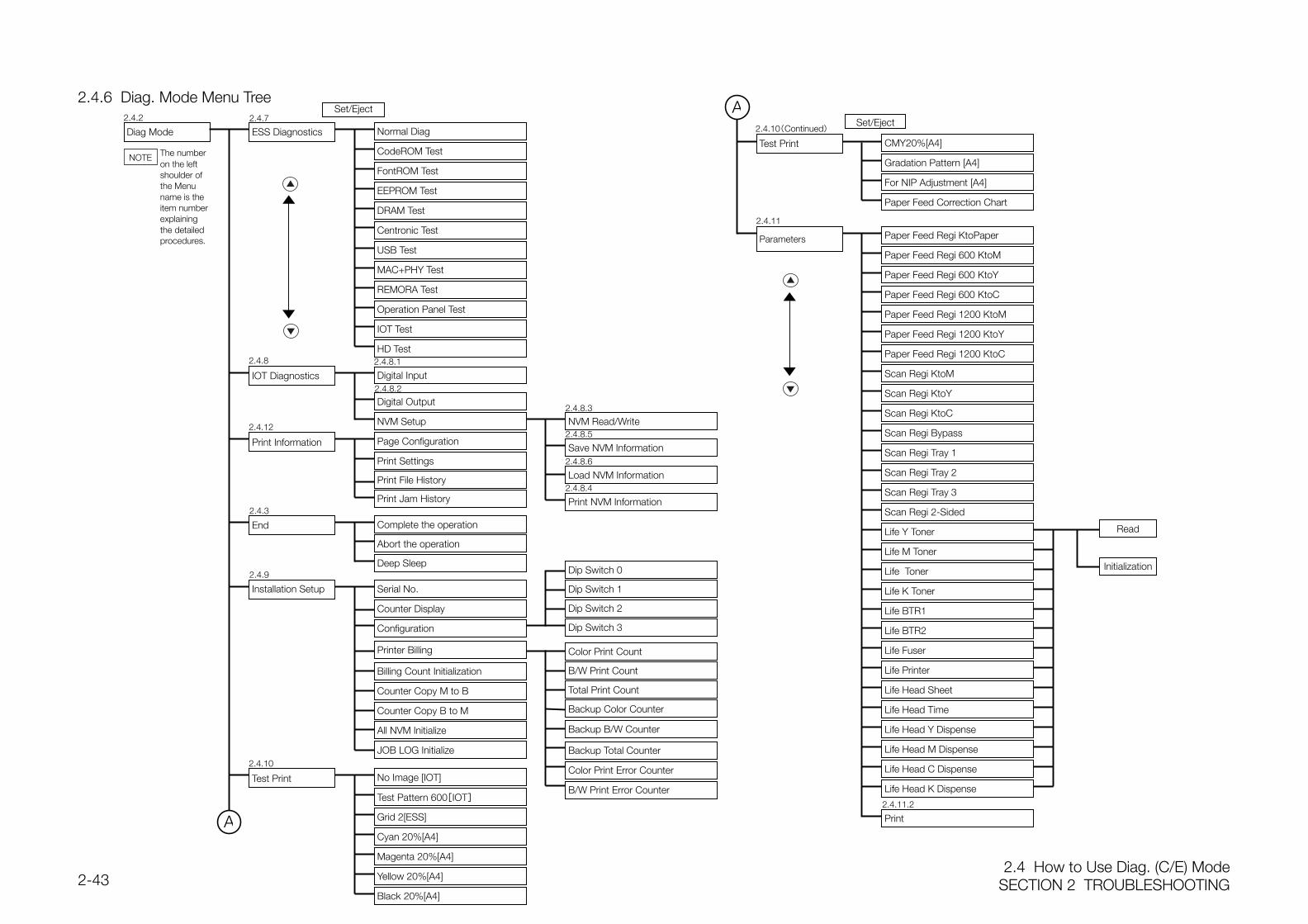
2.4 How to Use Diag. (C/E) ModeSECTION 2 TROUBLESHOOTING2-43
2.4.6 Diag. Mode Menu Tree
Paper Feed Regi KtoPaper
Paper Feed Regi 600 KtoM
Scan Regi KtoM
Set/Eject
CMY20%[A4]
For NIP Adjustment [A4]
Gradation Pattern [A4]
Diag Mode ESS Diagnostics
CodeROM Test
IOT Diagnostics
Print Information
FontROM Test
EEPROM Test
DRAM Test
Centronic Test
USB Test
REMORA Test
Operation Panel Test
HD Test
Digital Input
Digital Output
Page Configuration
Parameters
Normal Diag
Print Settings
MAC+PHY Test
NVM Setup NVM Read/Write
Save NVM Information
Load NVM Information
IOT Test
Print NVM Information
Paper Feed Regi 600 KtoY
Paper Feed Regi 600 KtoC
Paper Feed Regi 1200 KtoM
Paper Feed Regi 1200 KtoY
Paper Feed Regi 1200 KtoC
Scan Regi KtoY
Scan Regi KtoC
Scan Regi Bypass
Scan Regi Tray 1
Scan Regi Tray 2
Scan Regi Tray 3
Scan Regi 2-Sided
Life Y Toner
Life M Toner
Life Toner
Life K Toner
Life BTR1
Life BTR2
Life Fuser
Life Printer
Life Head Sheet
Life Head Time
Life Head Y Dispense
Life Head M Dispense
Life Head C Dispense
Life Head K Dispense
2.4.8 2.4.8.1
2.4.8.2
2.4.8.3
2.4.8.5
2.4.8.6
2.4.8.4
2.4.12
A
Test Print
2.4.10(Continued)
2.4.11
Read
Initialization
2.4.11.2
2.4.3
Test Pattern 600[IOT]
Magenta 20%[A4]
Yellow 20%[A4]
Grid 2[ESS]
Black 20%[A4]
Counter Copy M to B
Counter Copy B to M
End Complete the operation
Abort the operation
Serial No.
Counter Display
Printer Billing
Test Print
Installation Setup
Color Print Count
B/W Print Count
Total Print Count
Backup Color Counter
Backup B/W Counter
Backup Total Counter
B/W Print Error Counter
Color Print Error CounterNo Image [IOT]
Cyan 20%[A4]
Deep SleepDip Switch 0
Dip Switch 1
Dip Switch 2
Dip Switch 3
Billing Count Initialization
Configuration
2.4.9
2.4.10
All NVM Initialize
JOB LOG Initialize
Paper Feed Correction Chart
Print File History
Print Jam History
Set/Eject2.4.2 2.4.7
A
The numberon the leftshoulder ofthe Menuname is theitem numberexplainingthe detailedprocedures.
NOTE
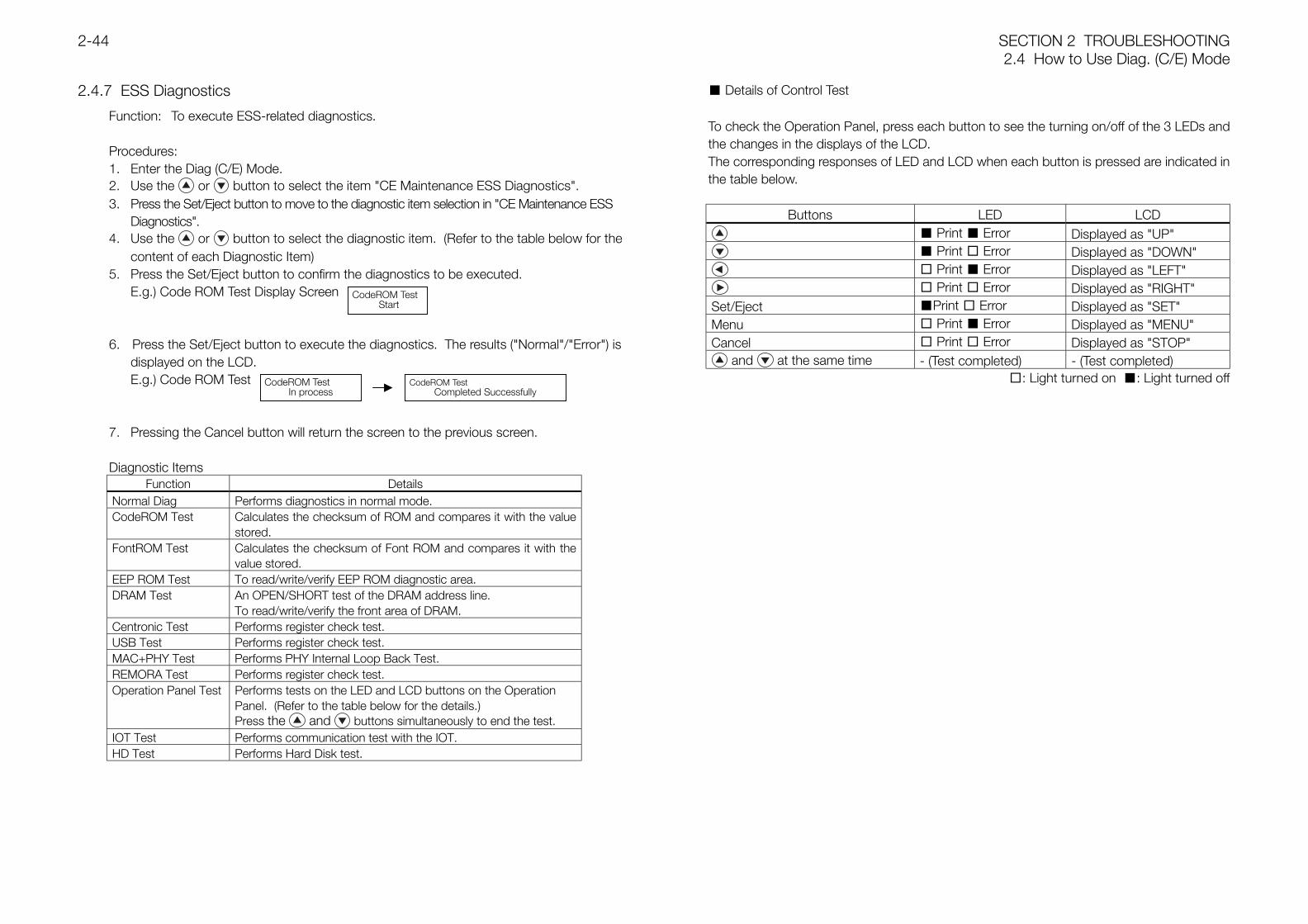
SECTION 2 TROUBLESHOOTING2.4 How to Use Diag. (C/E) Mode
2-44
2.4.7 ESS Diagnostics
Function: To execute ESS-related diagnostics.
Procedures:1. Enter the Diag (C/E) Mode.2. Use the or button to select the item "CE Maintenance ESS Diagnostics".3. Press the Set/Eject button to move to the diagnostic item selection in "CE Maintenance ESS
Diagnostics".4. Use the or button to select the diagnostic item. (Refer to the table below for the
content of each Diagnostic Item)5. Press the Set/Eject button to confirm the diagnostics to be executed.
E.g.) Code ROM Test Display Screen
6. Press the Set/Eject button to execute the diagnostics. The results ("Normal"/"Error") isdisplayed on the LCD.E.g.) Code ROM Test
7. Pressing the Cancel button will return the screen to the previous screen.
Diagnostic ItemsFunction Details
Normal Diag Performs diagnostics in normal mode.CodeROM Test Calculates the checksum of ROM and compares it with the value
stored.FontROM Test Calculates the checksum of Font ROM and compares it with the
value stored.EEP ROM Test To read/write/verify EEP ROM diagnostic area.DRAM Test An OPEN/SHORT test of the DRAM address line.
To read/write/verify the front area of DRAM.Centronic Test Performs register check test.USB Test Performs register check test.MAC+PHY Test Performs PHY Internal Loop Back Test.REMORA Test Performs register check test.Operation Panel Test Performs tests on the LED and LCD buttons on the Operation
Panel. (Refer to the table below for the details.)Press the and buttons simultaneously to end the test.
IOT Test Performs communication test with the IOT.HD Test Performs Hard Disk test.
Details of Control Test
To check the Operation Panel, press each button to see the turning on/off of the 3 LEDs andthe changes in the displays of the LCD.The corresponding responses of LED and LCD when each button is pressed are indicated inthe table below.
Buttons LED LCD Print Error Displayed as "UP" Print Error Displayed as "DOWN" Print Error Displayed as "LEFT" Print Error Displayed as "RIGHT"
Set/Eject Print Error Displayed as "SET"Menu Print Error Displayed as "MENU"Cancel Print Error Displayed as "STOP"
and at the same time - (Test completed) - (Test completed): Light turned on : Light turned off
CodeROM Test Start
CodeROM TestIn process
CodeROM TestCompleted Successfully
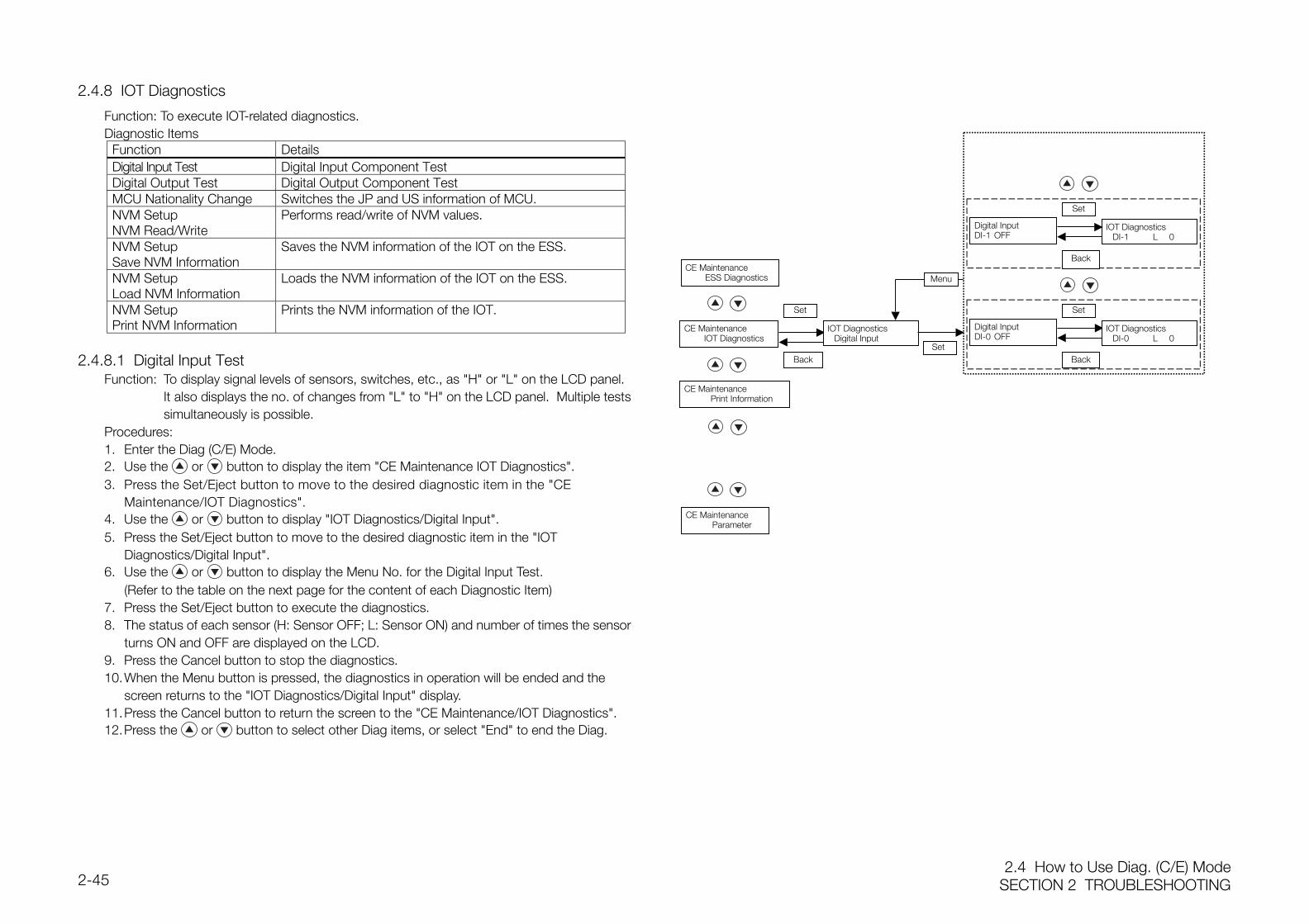
2.4 How to Use Diag. (C/E) ModeSECTION 2 TROUBLESHOOTING2-45
2.4.8 IOT Diagnostics
Function: To execute IOT-related diagnostics.Diagnostic Items
Function DetailsDigital Input Test Digital Input Component TestDigital Output Test Digital Output Component TestMCU Nationality Change Switches the JP and US information of MCU.NVM SetupNVM Read/Write
Performs read/write of NVM values.
NVM SetupSave NVM Information
Saves the NVM information of the IOT on the ESS.
NVM SetupLoad NVM Information
Loads the NVM information of the IOT on the ESS.
NVM SetupPrint NVM Information
Prints the NVM information of the IOT.
2.4.8.1 Digital Input TestFunction: To display signal levels of sensors, switches, etc., as "H" or "L" on the LCD panel.
It also displays the no. of changes from "L" to "H" on the LCD panel. Multiple testssimultaneously is possible.
Procedures:1. Enter the Diag (C/E) Mode.2. Use the or button to display the item "CE Maintenance IOT Diagnostics".3. Press the Set/Eject button to move to the desired diagnostic item in the "CE
Maintenance/IOT Diagnostics".4. Use the or button to display "IOT Diagnostics/Digital Input".5. Press the Set/Eject button to move to the desired diagnostic item in the "IOT
Diagnostics/Digital Input".6. Use the or button to display the Menu No. for the Digital Input Test.
(Refer to the table on the next page for the content of each Diagnostic Item)7. Press the Set/Eject button to execute the diagnostics.8. The status of each sensor (H: Sensor OFF; L: Sensor ON) and number of times the sensor
turns ON and OFF are displayed on the LCD.9. Press the Cancel button to stop the diagnostics.10.When the Menu button is pressed, the diagnostics in operation will be ended and the
screen returns to the "IOT Diagnostics/Digital Input" display.11.Press the Cancel button to return the screen to the "CE Maintenance/IOT Diagnostics".12.Press the or button to select other Diag items, or select "End" to end the Diag.
IOT DiagnosticsDI-1 L 0
Set
Back
Set
Back
CE MaintenanceIOT Diagnostics
CE MaintenancePrint Information
CE MaintenanceParameter
Set
Back
IOT DiagnosticsDigital Input
Set
Digital InputDI-0 OFF
Menu
Digital InputDI-1 OFF
IOT DiagnosticsDI-0 L 0
CE MaintenanceESS Diagnostics
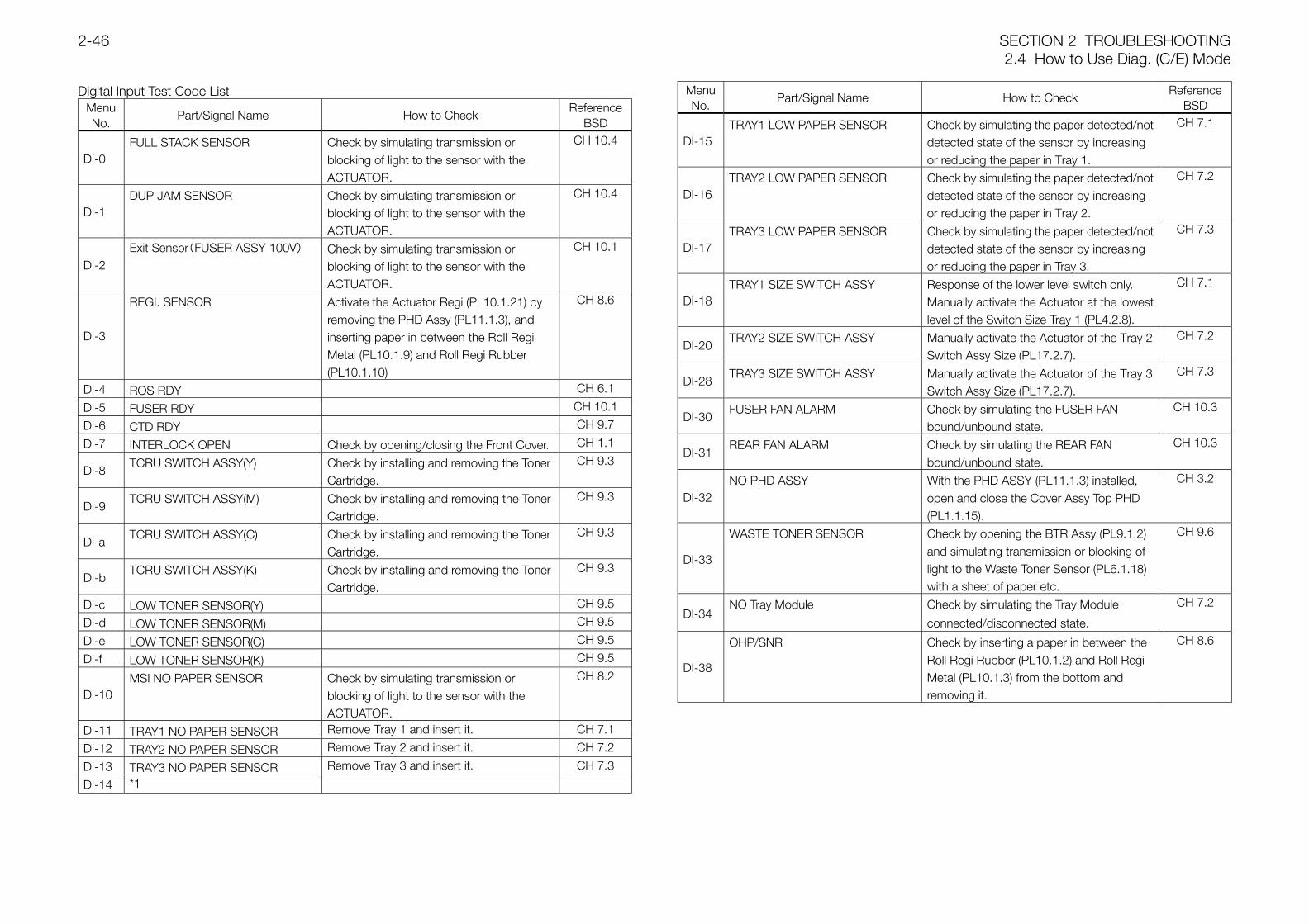
SECTION 2 TROUBLESHOOTING2.4 How to Use Diag. (C/E) Mode
2-46
Digital Input Test Code ListMenuNo.
Part/Signal Name How to CheckReference
BSD
DI-0FULL STACK SENSOR Check by simulating transmission or
blocking of light to the sensor with theACTUATOR.
CH 10.4
DI-1DUP JAM SENSOR Check by simulating transmission or
blocking of light to the sensor with theACTUATOR.
CH 10.4
DI-2Exit Sensor(FUSER ASSY 100V) Check by simulating transmission or
blocking of light to the sensor with theACTUATOR.
CH 10.1
DI-3
REGI. SENSOR Activate the Actuator Regi (PL10.1.21) byremoving the PHD Assy (PL11.1.3), andinserting paper in between the Roll RegiMetal (PL10.1.9) and Roll Regi Rubber(PL10.1.10)
CH 8.6
DI-4 ROS RDY CH 6.1
DI-5 FUSER RDY CH 10.1
DI-6 CTD RDY CH 9.7
DI-7 INTERLOCK OPEN Check by opening/closing the Front Cover. CH 1.1
DI-8TCRU SWITCH ASSY(Y) Check by installing and removing the Toner
Cartridge.
CH 9.3
DI-9TCRU SWITCH ASSY(M) Check by installing and removing the Toner
Cartridge.
CH 9.3
DI-aTCRU SWITCH ASSY(C) Check by installing and removing the Toner
Cartridge.
CH 9.3
DI-bTCRU SWITCH ASSY(K) Check by installing and removing the Toner
Cartridge.
CH 9.3
DI-c LOW TONER SENSOR(Y) CH 9.5
DI-d LOW TONER SENSOR(M) CH 9.5
DI-e LOW TONER SENSOR(C) CH 9.5
DI-f LOW TONER SENSOR(K) CH 9.5
DI-10MSI NO PAPER SENSOR Check by simulating transmission or
blocking of light to the sensor with theACTUATOR.
CH 8.2
DI-11 TRAY1 NO PAPER SENSOR Remove Tray 1 and insert it. CH 7.1
DI-12 TRAY2 NO PAPER SENSOR Remove Tray 2 and insert it. CH 7.2
DI-13 TRAY3 NO PAPER SENSOR Remove Tray 3 and insert it. CH 7.3
DI-14 *1
MenuNo.
Part/Signal Name How to CheckReference
BSD
DI-15TRAY1 LOW PAPER SENSOR Check by simulating the paper detected/not
detected state of the sensor by increasingor reducing the paper in Tray 1.
CH 7.1
DI-16TRAY2 LOW PAPER SENSOR Check by simulating the paper detected/not
detected state of the sensor by increasingor reducing the paper in Tray 2.
CH 7.2
DI-17TRAY3 LOW PAPER SENSOR Check by simulating the paper detected/not
detected state of the sensor by increasingor reducing the paper in Tray 3.
CH 7.3
DI-18TRAY1 SIZE SWITCH ASSY Response of the lower level switch only.
Manually activate the Actuator at the lowestlevel of the Switch Size Tray 1 (PL4.2.8).
CH 7.1
DI-20TRAY2 SIZE SWITCH ASSY Manually activate the Actuator of the Tray 2
Switch Assy Size (PL17.2.7).
CH 7.2
DI-28TRAY3 SIZE SWITCH ASSY Manually activate the Actuator of the Tray 3
Switch Assy Size (PL17.2.7).
CH 7.3
DI-30FUSER FAN ALARM Check by simulating the FUSER FAN
bound/unbound state.
CH 10.3
DI-31REAR FAN ALARM Check by simulating the REAR FAN
bound/unbound state.
CH 10.3
DI-32NO PHD ASSY With the PHD ASSY (PL11.1.3) installed,
open and close the Cover Assy Top PHD(PL1.1.15).
CH 3.2
DI-33
WASTE TONER SENSOR Check by opening the BTR Assy (PL9.1.2)and simulating transmission or blocking oflight to the Waste Toner Sensor (PL6.1.18)with a sheet of paper etc.
CH 9.6
DI-34NO Tray Module Check by simulating the Tray Module
connected/disconnected state.
CH 7.2
DI-38
OHP/SNR Check by inserting a paper in between theRoll Regi Rubber (PL10.1.2) and Roll RegiMetal (PL10.1.3) from the bottom andremoving it.
CH 8.6
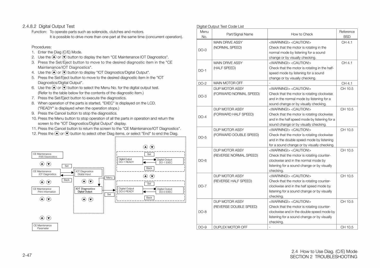
2.4 How to Use Diag. (C/E) ModeSECTION 2 TROUBLESHOOTING2-47
2.4.8.2 Digital Output TestFunction: To operate parts such as solenoids, clutches and motors.
It is possible to drive more than one part at the same time (concurrent operation).
Procedures:1. Enter the Diag (C/E) Mode.2. Use the or button to display the item "CE Maintenance IOT Diagnostics".3. Press the Set/Eject button to move to the desired diagnostic item in the "CE
Maintenance/IOT Diagnostics".4. Use the or button to display "IOT Diagnostics/Digital Output".5. Press the Set/Eject button to move to the desired diagnostic item in the "IOT
Diagnostics/Digital Output".6. Use the or button to select the Menu No. for the digital output test.
(Refer to the table below for the contents of the diagnostic item.)7. Press the Set/Eject button to execute the diagnostics.8. When operation of the parts is started, "EXEC" is displayed on the LCD.
("READY" is displayed when the operation stops.)9. Press the Cancel button to stop the diagnostics.10. Press the Menu button to stop operation of all the parts in operation and return the
screen to the "IOT Diagnostics/Digital Output" display.11. Press the Cancel button to return the screen to the "CE Maintenance/IOT Diagnostics".12. Press the or button to select other Diag items, or select "End" to end the Diag.
Digital Output Test Code ListMenuNo.
Part/Signal Name How to CheckReference
BSD
DO-0
MAIN DRIVE ASSY(NORMAL SPEED)
<WARNING!> <CAUTION!>Check that the motor is rotating in thenormal mode by listening for a soundchange or by visually checking.
CH 4.1
DO-1
MAIN DRIVE ASSY(HALF SPEED)
<WARNING!> <CAUTION!>Check that the motor is rotating in the half-speed mode by listening for a soundchange or by visually checking.
CH 4.1
DO-2 MAIN MOTOR OFF - CH 4.1
DO-3
DUP MOTOR ASSY(FORWARD NORMAL SPEED)
<WARNING!> <CAUTION!>Check that the motor is rotating clockwiseand in the normal mode by listening for asound change or by visually checking.
CH 10.5
DO-4
DUP MOTOR ASSY(FORWARD HALF SPEED)
<WARNING!> <CAUTION!>Check that the motor is rotating clockwiseand in the half speed mode by listening for asound change or by visually checking.
CH 10.5
DO-5
DUP MOTOR ASSY(FORWARD DOUBLE SPEED)
<WARNING!> <CAUTION!>Check that the motor is rotating clockwiseand in the double speed mode by listeningfor a sound change or by visually checking.
CH 10.5
DO-6
DUP MOTOR ASSY(REVERSE NORMAL SPEED)
<WARNING!> <CAUTION!>Check that the motor is rotating counter-clockwise and in the normal mode bylistening for a sound change or by visuallychecking.
CH 10.5
DO-7
DUP MOTOR ASSY(REVERSE HALF SPEED)
<WARNING!> <CAUTION!>Check that the motor is rotating counter-clockwise and in the half speed mode bylistening for a sound change or by visuallychecking.
CH 10.5
DO-8
DUP MOTOR ASSY(REVERSE DOUBLE SPEED)
<WARNING!> <CAUTION!>Check that the motor is rotating counter-clockwise and in the double speed mode bylistening for a sound change or by visuallychecking.
CH 10.5
DO-9 DUPLEX MOTOR OFF - CH 10.5
IOT DiagnosticsDigital Output
Digital OutputDO-1 READY
CE MaintenanceESS Diagnostics
CE MaintenanceIOT Diagnostics
CE MaintenancePrint Information
CE MaintenanceParameter
Set
Back
IOT DiagnosticsDigital Input
Set
Digital OutputDO-0 READY
Digital OutputDO-0 EXEC
Back
Digital OutputDO-1 EXEC
Menu
Back
Set
Set
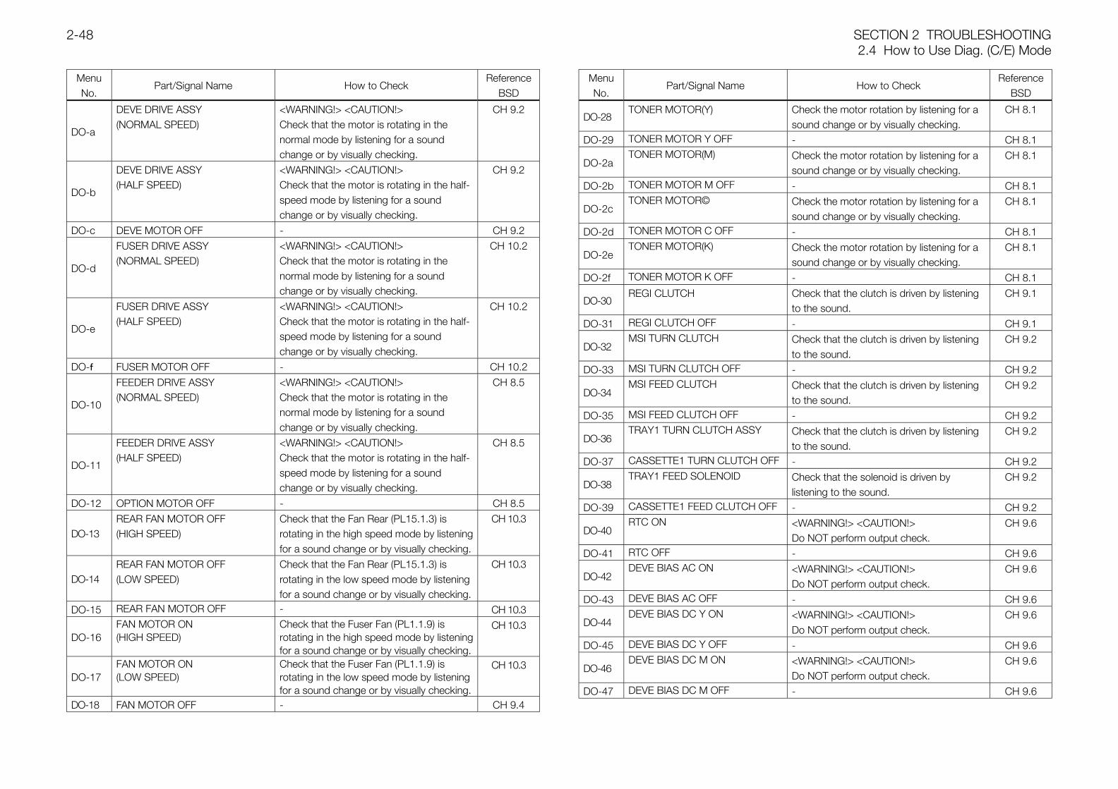
SECTION 2 TROUBLESHOOTING2.4 How to Use Diag. (C/E) Mode
2-48
MenuNo.
Part/Signal Name How to CheckReference
BSD
DO-a
DEVE DRIVE ASSY(NORMAL SPEED)
<WARNING!> <CAUTION!>Check that the motor is rotating in thenormal mode by listening for a soundchange or by visually checking.
CH 9.2
DO-b
DEVE DRIVE ASSY(HALF SPEED)
<WARNING!> <CAUTION!>Check that the motor is rotating in the half-speed mode by listening for a soundchange or by visually checking.
CH 9.2
DO-c DEVE MOTOR OFF - CH 9.2
DO-d
FUSER DRIVE ASSY(NORMAL SPEED)
<WARNING!> <CAUTION!>Check that the motor is rotating in thenormal mode by listening for a soundchange or by visually checking.
CH 10.2
DO-e
FUSER DRIVE ASSY(HALF SPEED)
<WARNING!> <CAUTION!>Check that the motor is rotating in the half-speed mode by listening for a soundchange or by visually checking.
CH 10.2
DO-f FUSER MOTOR OFF - CH 10.2
DO-10
FEEDER DRIVE ASSY(NORMAL SPEED)
<WARNING!> <CAUTION!>Check that the motor is rotating in thenormal mode by listening for a soundchange or by visually checking.
CH 8.5
DO-11
FEEDER DRIVE ASSY(HALF SPEED)
<WARNING!> <CAUTION!>Check that the motor is rotating in the half-speed mode by listening for a soundchange or by visually checking.
CH 8.5
DO-12 OPTION MOTOR OFF - CH 8.5
DO-13REAR FAN MOTOR OFF(HIGH SPEED)
Check that the Fan Rear (PL15.1.3) isrotating in the high speed mode by listeningfor a sound change or by visually checking.
CH 10.3
DO-14REAR FAN MOTOR OFF(LOW SPEED)
Check that the Fan Rear (PL15.1.3) isrotating in the low speed mode by listeningfor a sound change or by visually checking.
CH 10.3
DO-15 REAR FAN MOTOR OFF - CH 10.3
DO-16FAN MOTOR ON(HIGH SPEED)
Check that the Fuser Fan (PL1.1.9) isrotating in the high speed mode by listeningfor a sound change or by visually checking.
CH 10.3
DO-17FAN MOTOR ON(LOW SPEED)
Check that the Fuser Fan (PL1.1.9) isrotating in the low speed mode by listeningfor a sound change or by visually checking.
CH 10.3
DO-18 FAN MOTOR OFF - CH 9.4
MenuNo.
Part/Signal Name How to CheckReference
BSD
DO-28TONER MOTOR(Y) Check the motor rotation by listening for a
sound change or by visually checking.CH 8.1
DO-29 TONER MOTOR Y OFF - CH 8.1
DO-2aTONER MOTOR(M) Check the motor rotation by listening for a
sound change or by visually checking.CH 8.1
DO-2b TONER MOTOR M OFF - CH 8.1
DO-2cTONER MOTOR© Check the motor rotation by listening for a
sound change or by visually checking.CH 8.1
DO-2d TONER MOTOR C OFF - CH 8.1
DO-2eTONER MOTOR(K) Check the motor rotation by listening for a
sound change or by visually checking.CH 8.1
DO-2f TONER MOTOR K OFF - CH 8.1
DO-30REGI CLUTCH Check that the clutch is driven by listening
to the sound.CH 9.1
DO-31 REGI CLUTCH OFF - CH 9.1
DO-32MSI TURN CLUTCH Check that the clutch is driven by listening
to the sound.CH 9.2
DO-33 MSI TURN CLUTCH OFF - CH 9.2
DO-34MSI FEED CLUTCH Check that the clutch is driven by listening
to the sound.CH 9.2
DO-35 MSI FEED CLUTCH OFF - CH 9.2
DO-36TRAY1 TURN CLUTCH ASSY Check that the clutch is driven by listening
to the sound.CH 9.2
DO-37 CASSETTE1 TURN CLUTCH OFF - CH 9.2
DO-38TRAY1 FEED SOLENOID Check that the solenoid is driven by
listening to the sound.CH 9.2
DO-39 CASSETTE1 FEED CLUTCH OFF - CH 9.2
DO-40RTC ON <WARNING!> <CAUTION!>
Do NOT perform output check.CH 9.6
DO-41 RTC OFF - CH 9.6
DO-42DEVE BIAS AC ON <WARNING!> <CAUTION!>
Do NOT perform output check.CH 9.6
DO-43 DEVE BIAS AC OFF - CH 9.6
DO-44DEVE BIAS DC Y ON <WARNING!> <CAUTION!>
Do NOT perform output check.CH 9.6
DO-45 DEVE BIAS DC Y OFF - CH 9.6
DO-46DEVE BIAS DC M ON <WARNING!> <CAUTION!>
Do NOT perform output check.CH 9.6
DO-47 DEVE BIAS DC M OFF - CH 9.6
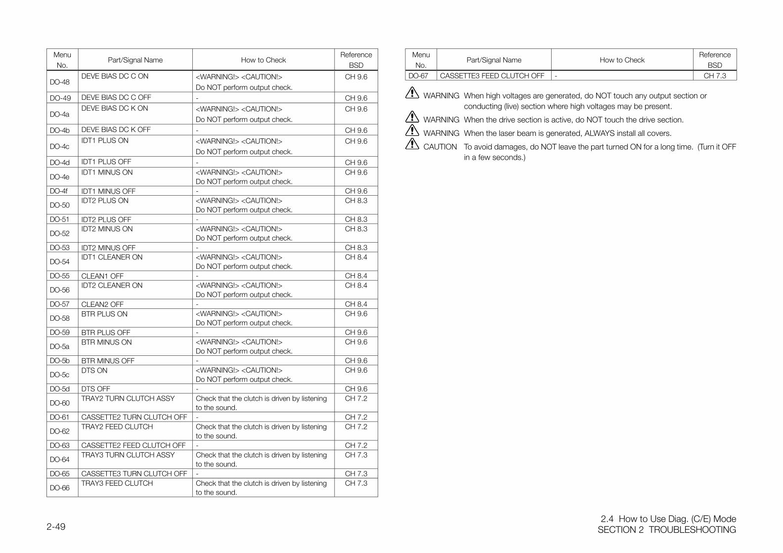
2.4 How to Use Diag. (C/E) ModeSECTION 2 TROUBLESHOOTING2-49
MenuNo.
Part/Signal Name How to CheckReference
BSD
DO-48DEVE BIAS DC C ON <WARNING!> <CAUTION!>
Do NOT perform output check.CH 9.6
DO-49 DEVE BIAS DC C OFF - CH 9.6
DO-4aDEVE BIAS DC K ON <WARNING!> <CAUTION!>
Do NOT perform output check.CH 9.6
DO-4b DEVE BIAS DC K OFF - CH 9.6
DO-4cIDT1 PLUS ON <WARNING!> <CAUTION!>
Do NOT perform output check.CH 9.6
DO-4d IDT1 PLUS OFF - CH 9.6
DO-4eIDT1 MINUS ON <WARNING!> <CAUTION!>
Do NOT perform output check.CH 9.6
DO-4f IDT1 MINUS OFF - CH 9.6
DO-50IDT2 PLUS ON <WARNING!> <CAUTION!>
Do NOT perform output check.CH 8.3
DO-51 IDT2 PLUS OFF - CH 8.3
DO-52IDT2 MINUS ON <WARNING!> <CAUTION!>
Do NOT perform output check.CH 8.3
DO-53 IDT2 MINUS OFF - CH 8.3
DO-54IDT1 CLEANER ON <WARNING!> <CAUTION!>
Do NOT perform output check.CH 8.4
DO-55 CLEAN1 OFF - CH 8.4
DO-56IDT2 CLEANER ON <WARNING!> <CAUTION!>
Do NOT perform output check.CH 8.4
DO-57 CLEAN2 OFF - CH 8.4
DO-58 BTR PLUS ON <WARNING!> <CAUTION!>Do NOT perform output check.
CH 9.6
DO-59 BTR PLUS OFF - CH 9.6
DO-5a BTR MINUS ON <WARNING!> <CAUTION!>Do NOT perform output check.
CH 9.6
DO-5b BTR MINUS OFF - CH 9.6
DO-5c DTS ON <WARNING!> <CAUTION!>Do NOT perform output check.
CH 9.6
DO-5d DTS OFF - CH 9.6
DO-60TRAY2 TURN CLUTCH ASSY Check that the clutch is driven by listening
to the sound.CH 7.2
DO-61 CASSETTE2 TURN CLUTCH OFF - CH 7.2
DO-62TRAY2 FEED CLUTCH Check that the clutch is driven by listening
to the sound.CH 7.2
DO-63 CASSETTE2 FEED CLUTCH OFF - CH 7.2
DO-64TRAY3 TURN CLUTCH ASSY Check that the clutch is driven by listening
to the sound.CH 7.3
DO-65 CASSETTE3 TURN CLUTCH OFF - CH 7.3
DO-66TRAY3 FEED CLUTCH Check that the clutch is driven by listening
to the sound.CH 7.3
MenuNo.
Part/Signal Name How to CheckReference
BSDDO-67 CASSETTE3 FEED CLUTCH OFF - CH 7.3
WARNING When high voltages are generated, do NOT touch any output section orconducting (live) section where high voltages may be present.
WARNING When the drive section is active, do NOT touch the drive section.
WARNING When the laser beam is generated, ALWAYS install all covers.
CAUTION To avoid damages, do NOT leave the part turned ON for a long time. (Turn it OFFin a few seconds.)
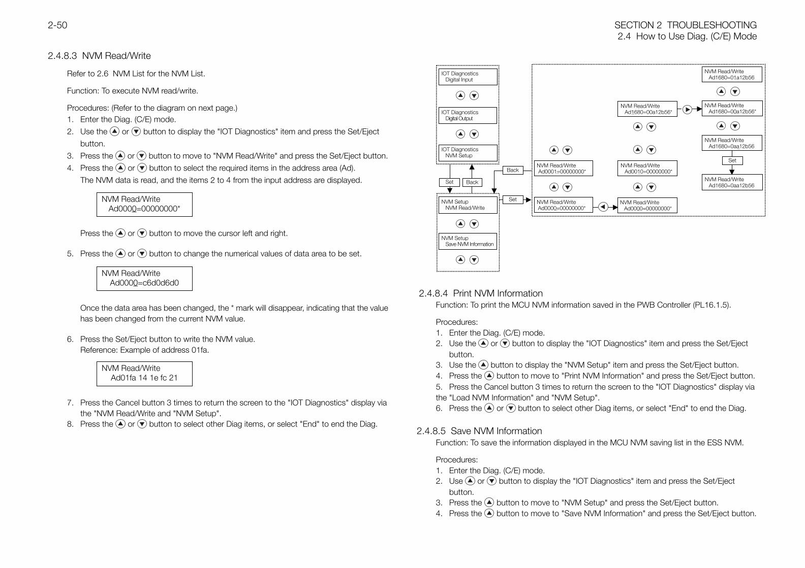
SECTION 2 TROUBLESHOOTING2.4 How to Use Diag. (C/E) Mode
2-50
2.4.8.3 NVM Read/Write
Refer to 2.6 NVM List for the NVM List.
Function: To execute NVM read/write.
Procedures: (Refer to the diagram on next page.)1. Enter the Diag. (C/E) mode.
2. Use the or button to display the "IOT Diagnostics" item and press the Set/Eject
button.
3. Press the or button to move to "NVM Read/Write" and press the Set/Eject button.
4. Press the or button to select the required items in the address area (Ad).
The NVM data is read, and the items 2 to 4 from the input address are displayed.
Press the or button to move the cursor left and right.
5. Press the or button to change the numerical values of data area to be set.
Once the data area has been changed, the * mark will disappear, indicating that the valuehas been changed from the current NVM value.
6. Press the Set/Eject button to write the NVM value.Reference: Example of address 01fa.
7. Press the Cancel button 3 times to return the screen to the "IOT Diagnostics" display viathe "NVM Read/Write and "NVM Setup".
8. Press the or button to select other Diag items, or select "End" to end the Diag.
2.4.8.4 Print NVM InformationFunction: To print the MCU NVM information saved in the PWB Controller (PL16.1.5).
Procedures:1. Enter the Diag. (C/E) mode.2. Use the or button to display the "IOT Diagnostics" item and press the Set/Eject
button.3. Use the button to display the "NVM Setup" item and press the Set/Eject button.4. Press the button to move to "Print NVM Information" and press the Set/Eject button.5. Press the Cancel button 3 times to return the screen to the "IOT Diagnostics" display via the "Load NVM Information" and "NVM Setup".6. Press the or button to select other Diag items, or select "End" to end the Diag.
2.4.8.5 Save NVM InformationFunction: To save the information displayed in the MCU NVM saving list in the ESS NVM.
Procedures:1. Enter the Diag. (C/E) mode.2. Use or button to display the "IOT Diagnostics" item and press the Set/Eject
button.3. Press the button to move to "NVM Setup" and press the Set/Eject button.4. Press the button to move to "Save NVM Information" and press the Set/Eject button.
NVM Read/WriteAd0000=00000000*
NVM Read/WriteAd0000=c6d0d6d0
NVM Read/WriteAd01fa 14 1e fc 21
NVM Read/WriteAd0000=00000000*
NVM Setup NVM Read/Write
NVM Read/WriteAd1680=00a12b56*
NVM Read/WriteAd1680=0aa12b56
NVM Read/WriteAd1680=01a12b56
NVM Read/WriteAd1680=00a12b56*
IOT DiagnosticsDigital Input
IOT DiagnosticsDigital Output
IOT DiagnosticsNVM Setup
NVM Read/Write Ad0001=00000000*
Set Back
Set
BackNVM Read/Write
Ad0010=00000000*
Set
NVM Read/Write Ad0000=00000000*
NVM Read/WriteAd1680=0aa12b56
NVM SetupSave NVM Information
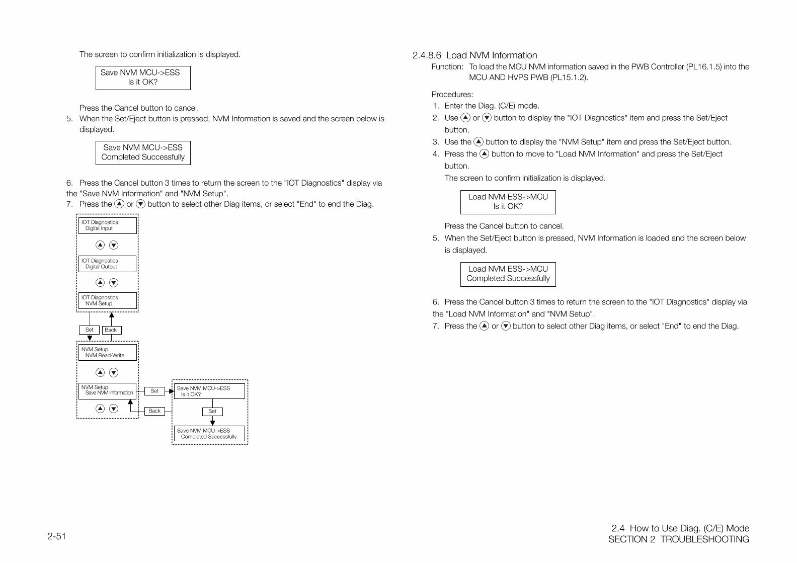
2.4 How to Use Diag. (C/E) ModeSECTION 2 TROUBLESHOOTING2-51
The screen to confirm initialization is displayed.
Press the Cancel button to cancel.5. When the Set/Eject button is pressed, NVM Information is saved and the screen below is
displayed.
6. Press the Cancel button 3 times to return the screen to the "IOT Diagnostics" display via the "Save NVM Information" and "NVM Setup".7. Press the or button to select other Diag items, or select "End" to end the Diag.
2.4.8.6 Load NVM InformationFunction: To load the MCU NVM information saved in the PWB Controller (PL16.1.5) into the
MCU AND HVPS PWB (PL15.1.2).
Procedures:1. Enter the Diag. (C/E) mode.
2. Use or button to display the "IOT Diagnostics" item and press the Set/Eject
button.
3. Use the button to display the "NVM Setup" item and press the Set/Eject button.
4. Press the button to move to "Load NVM Information" and press the Set/Eject
button.
The screen to confirm initialization is displayed.
Press the Cancel button to cancel.
5. When the Set/Eject button is pressed, NVM Information is loaded and the screen below
is displayed.
6. Press the Cancel button 3 times to return the screen to the "IOT Diagnostics" display via
the "Load NVM Information" and "NVM Setup".
7. Press the or button to select other Diag items, or select "End" to end the Diag.
Save NVM MCU->ESSIs it OK?
Save NVM MCU->ESSCompleted Successfully
Load NVM ESS->MCUIs it OK?
Load NVM ESS->MCUCompleted Successfully
Save NVM MCU->ESSCompleted Successfully
IOT DiagnosticsDigital Input
IOT DiagnosticsDigital Output
IOT DiagnosticsNVM Setup
Save NVM MCU->ESSIs it OK?
NVM SetupNVM Read/Write
NVM SetupSave NVM Information
Set Back
Set
Back Set
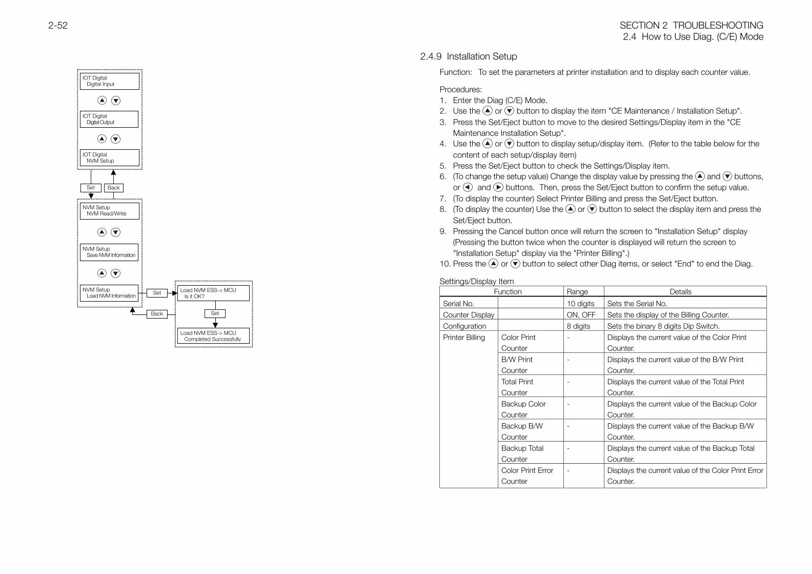
SECTION 2 TROUBLESHOOTING2.4 How to Use Diag. (C/E) Mode
2-52
2.4.9 Installation Setup
Function: To set the parameters at printer installation and to display each counter value.
Procedures:1. Enter the Diag (C/E) Mode.2. Use the or button to display the item "CE Maintenance / Installation Setup".3. Press the Set/Eject button to move to the desired Settings/Display item in the "CE
Maintenance Installation Setup".4. Use the or button to display setup/display item. (Refer to the table below for the
content of each setup/display item)5. Press the Set/Eject button to check the Settings/Display item.6. (To change the setup value) Change the display value by pressing the and buttons,
or and buttons. Then, press the Set/Eject button to confirm the setup value.7. (To display the counter) Select Printer Billing and press the Set/Eject button.8. (To display the counter) Use the or button to select the display item and press the
Set/Eject button.9. Pressing the Cancel button once will return the screen to "Installation Setup" display
(Pressing the button twice when the counter is displayed will return the screen to "Installation Setup" display via the "Printer Billing".)
10. Press the or button to select other Diag items, or select "End" to end the Diag.
Settings/Display ItemFunction Range Details
Serial No. 10 digits Sets the Serial No.
Counter Display ON, OFF Sets the display of the Billing Counter.
Configuration 8 digits Sets the binary 8 digits Dip Switch.
Color PrintCounter
- Displays the current value of the Color PrintCounter.
B/W PrintCounter
- Displays the current value of the B/W PrintCounter.
Total PrintCounter
- Displays the current value of the Total PrintCounter.
Backup ColorCounter
- Displays the current value of the Backup ColorCounter.
Backup B/WCounter
- Displays the current value of the Backup B/WCounter.
Backup TotalCounter
- Displays the current value of the Backup TotalCounter.
Printer Billing
Color Print ErrorCounter
- Displays the current value of the Color Print ErrorCounter.
NVM SetupNVM Read/Write
Load NVM ESS-> MCUCompleted Successfully
IOT Digital Digital Input
IOT Digital Digital Output
IOT DigitalNVM Setup
Load NVM ESS-> MCUIs it OK?
Set Back
Set
Back
NVM SetupSave NVM Information
Set
NVM SetupLoad NVM Information
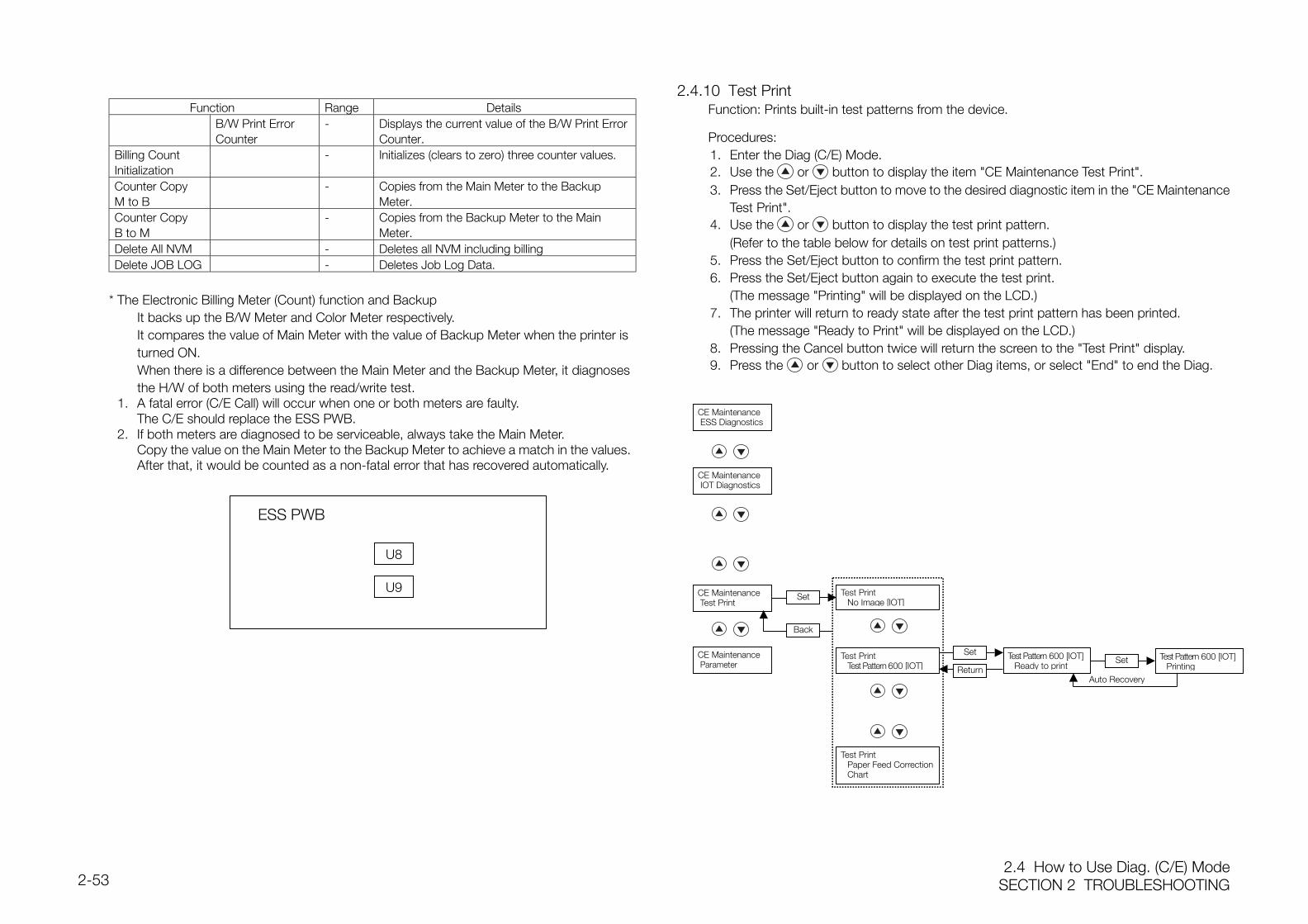
2.4 How to Use Diag. (C/E) ModeSECTION 2 TROUBLESHOOTING2-53
Function Range DetailsB/W Print ErrorCounter
- Displays the current value of the B/W Print ErrorCounter.
Billing CountInitialization
- Initializes (clears to zero) three counter values.
Counter CopyM to B
- Copies from the Main Meter to the BackupMeter.
Counter CopyB to M
- Copies from the Backup Meter to the MainMeter.
Delete All NVM - Deletes all NVM including billingDelete JOB LOG - Deletes Job Log Data.
* The Electronic Billing Meter (Count) function and BackupIt backs up the B/W Meter and Color Meter respectively.It compares the value of Main Meter with the value of Backup Meter when the printer isturned ON.When there is a difference between the Main Meter and the Backup Meter, it diagnosesthe H/W of both meters using the read/write test.
1. A fatal error (C/E Call) will occur when one or both meters are faulty.The C/E should replace the ESS PWB.
2. If both meters are diagnosed to be serviceable, always take the Main Meter.Copy the value on the Main Meter to the Backup Meter to achieve a match in the values.After that, it would be counted as a non-fatal error that has recovered automatically.
2.4.10 Test PrintFunction: Prints built-in test patterns from the device.
Procedures:1. Enter the Diag (C/E) Mode.2. Use the or button to display the item "CE Maintenance Test Print".3. Press the Set/Eject button to move to the desired diagnostic item in the "CE Maintenance
Test Print".4. Use the or button to display the test print pattern.
(Refer to the table below for details on test print patterns.)5. Press the Set/Eject button to confirm the test print pattern.6. Press the Set/Eject button again to execute the test print.
(The message "Printing" will be displayed on the LCD.)7. The printer will return to ready state after the test print pattern has been printed.
(The message "Ready to Print" will be displayed on the LCD.)8. Pressing the Cancel button twice will return the screen to the "Test Print" display.9. Press the or button to select other Diag items, or select "End" to end the Diag.
CE Maintenance Test Print
Test PrintPaper Feed CorrectionChart
U9
ESS PWB
U8
CE Maintenance ESS Diagnostics
CE Maintenance IOT Diagnostics
Test PrintNo Image [IOT]
Back
CE Maintenance Parameter
Set Test Pattern 600 [IOT]Ready to print
Set Test Pattern 600 [IOT]PrintingReturn
Auto Recovery
Set
Test PrintTest Pattern 600 [IOT]
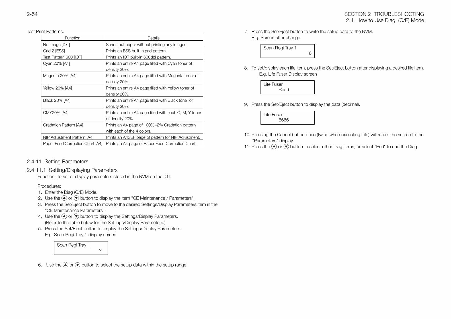
SECTION 2 TROUBLESHOOTING2.4 How to Use Diag. (C/E) Mode
2-54
Test Print Patterns:Function Details
No Image [IOT] Sends out paper without printing any images.
Grid 2 [ESS] Prints an ESS built-in grid pattern.
Test Pattern 600 [IOT] Prints an IOT built-in 600dpi pattern.
Cyan 20% [A4] Prints an entire A4 page filled with Cyan toner ofdensity 20%.
Magenta 20% [A4] Prints an entire A4 page filled with Magenta toner ofdensity 20%.
Yellow 20% [A4] Prints an entire A4 page filled with Yellow toner ofdensity 20%.
Black 20% [A4] Prints an entire A4 page filled with Black toner ofdensity 20%.
CMY20% [A4] Prints an entire A4 page filled with each C, M, Y tonerof density 20%.
Gradation Pattern [A4] Prints an A4 page of 100%~2% Gradation patternwith each of the 4 colors.
NIP Adjustment Pattern [A4] Prints an A4SEF page of pattern for NIP Adjustment.
Paper Feed Correction Chart [A4] Prints an A4 page of Paper Feed Correction Chart.
2.4.11 Setting Parameters
2.4.11.1 Setting/Displaying ParametersFunction: To set or display parameters stored in the NVM on the IOT.
Procedures:1. Enter the Diag (C/E) Mode.2. Use the or button to display the item "CE Maintenance / Parameters".3. Press the Set/Eject button to move to the desired Settings/Display Parameters item in the
"CE Maintenance Parameters".4. Use the or button to display the Settings/Display Parameters.
(Refer to the table below for the Settings/Display Parameters.)5. Press the Set/Eject button to display the Settings/Display Parameters.
E.g. Scan Regi Tray 1 display screen
6. Use the or button to select the setup data within the setup range.
7. Press the Set/Eject button to write the setup data to the NVM.E.g. Screen after change
8. To set/display each life item, press the Set/Eject button after displaying a desired life item.E.g. Life Fuser Display screen
9. Press the Set/Eject button to display the data (decimal).
10. Pressing the Cancel button once (twice when executing Life) will return the screen to the"Parameters" display.
11. Press the or button to select other Diag items, or select "End" to end the Diag.
Scan Regi Tray 1 *4
Scan Regi Tray 1 6
Life Fuser Read
Life Fuser 6666
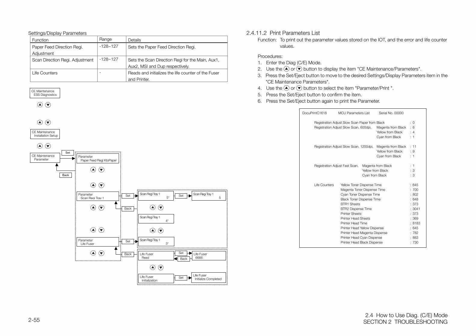
2.4 How to Use Diag. (C/E) ModeSECTION 2 TROUBLESHOOTING2-55
Settings/Display ParametersFunction Range Details
Paper Feed Direction Regi.Adjustment
-128~127 Sets the Paper Feed Direction Regi.
Scan Direction Regi. Adjustment -128~127 Sets the Scan Direction Regi for the Main, Aux1,Aux2, MSI and Dup respectively.
Life Counters - Reads and initializes the life counter of the Fuserand Printer.
2.4.11.2 Print Parameters ListFunction: To print out the parameter values stored on the IOT, and the error and life counter
values.
Procedures:1. Enter the Diag (C/E) Mode.2. Use the or button to display the item "CE Maintenance/Parameters".3. Press the Set/Eject button to move to the desired Settings/Display Parameters item in the
"CE Maintenance Parameters".4. Use the or button to select the item "Parameter/Print ".5. Press the Set/Eject button to confirm the item.6. Press the Set/Eject button again to print the Parameter.
ParameterScan Regi Tray 1
ParameterLife Fuser
Scan Regi Tray 1 4*
Scan Regi Tray 1 3*
Life Fuser Initialization
DocuPrintC1618 MCU Parameters List Serial No. 00000
Registration Adjust Slow Scan Paper from Black : 0Registration Adjust Slow Scan, 600dpi, Magenta from Black : 6
Yellow from Black : 4Cyan from Black : 1
Registration Adjust Slow Scan, 1200dpi, Magenta from Black : 11Yellow from Black : 9Cyan from Black : 1
Registration Adjust Fast Scan, Magenta from Black : 1Yellow from Black : 3Cyan from Black : 3
Life Counters Yellow Toner Dispense Time : 645Magenta Toner Dispense Time : 700Cyan Toner Dispense Time : 802Black Toner Dispense Time : 648BTR1 Sheets : 373BTR2 Dispense Time : 3041Printer Sheets : 373Printer Head Sheets : 369Printer Head Time : 8183Printer Head Yellow Dispense : 645Printer Head Magenta Dispense : 782Printer Head Cyan Dispense : 883Printer Head Black Dispense : 730
CE MaintenanceESS Diagnostics
CE MaintenanceInstallation Setup
ParameterPaper Feed Regi KtoPaper
Set
Set Scan Regi Tray 15*
Back
Back
Set Scan Regi Tray 1 5
Life Fuser 6666
Life Fuser Initialize CompletedSet
Set
Back
Set
Back
CE MaintenanceParameter
Life Fuser Read
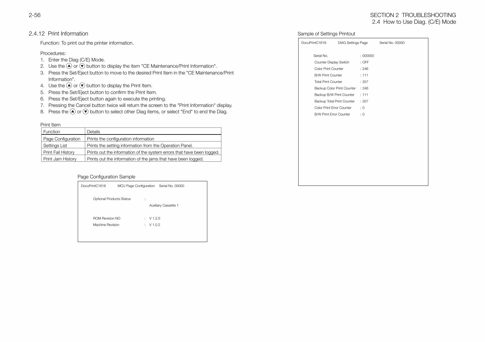
SECTION 2 TROUBLESHOOTING2.4 How to Use Diag. (C/E) Mode
2-56
2.4.12 Print Information
Function: To print out the printer information.
Procedures:1. Enter the Diag (C/E) Mode.2. Use the or button to display the item "CE Maintenance/Print Information".3. Press the Set/Eject button to move to the desired Print Item in the "CE Maintenance/Print
Information".4. Use the or button to display the Print Item.5. Press the Set/Eject button to confirm the Print Item.6. Press the Set/Eject button again to execute the printing.7. Pressing the Cancel button twice will return the screen to the "Print Information" display.8. Press the or button to select other Diag items, or select "End" to end the Diag.
Print ItemFunction Details
Page Configuration Prints the configuration information
Settings List Prints the setting information from the Operation Panel.
Print Fail History Prints out the information of the system errors that have been logged.
Print Jam History Prints out the information of the jams that have been logged.
DocuPrintC1618 MCU Page Configuration Serial No. 00000
Optional Products Status :
Auxiliary Cassette 1
ROM Revision NO : V 1.2.0
Machine Revision : V 1.0.2
Sample of Settings Printout
Page Configuration Sample
DocuPrintC1618 DIAG Settings Page Serial No. 00000
Serial No. : 000000
Counter Display Switch : OFF
Color Print Counter : 246
B/W Print Counter : 111
Total Print Counter : 357
Backup Color Print Counter : 246
Backup B/W Print Counter : 111
Backup Total Print Counter : 357
Color Print Error Counter : 0
B/W Print Error Counter : 0
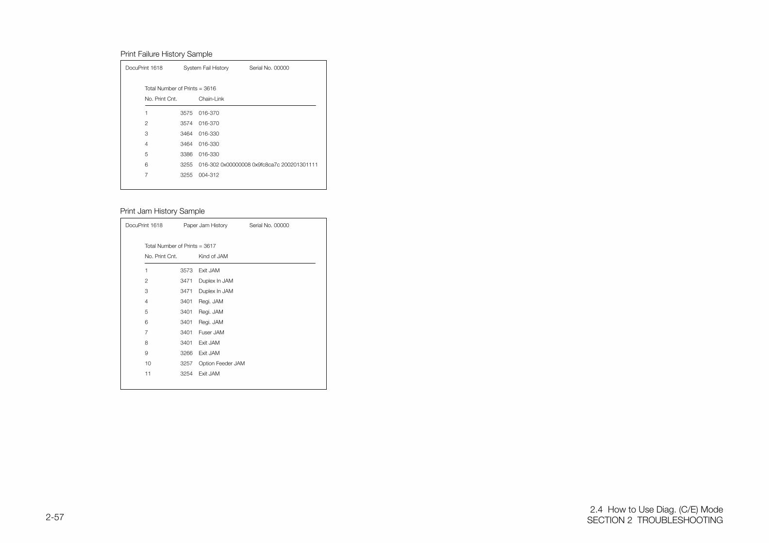
2.4 How to Use Diag. (C/E) ModeSECTION 2 TROUBLESHOOTING2-57
Print Failure History Sample
DocuPrint 1618 System Fail History Serial No. 00000
Total Number of Prints = 3616
No. Print Cnt. Chain-Link
1 3575 016-370
2 3574 016-370
3 3464 016-330
4 3464 016-330
5 3386 016-330
6 3255 016-302 0x00000008 0x9fc8ca7c 200201301111
7 3255 004-312
Print Jam History Sample
DocuPrint 1618 Paper Jam History Serial No. 00000
Total Number of Prints = 3617
No. Print Cnt. Kind of JAM
1 3573 Exit JAM
2 3471 Duplex In JAM
3 3471 Duplex In JAM
4 3401 Regi. JAM
5 3401 Regi. JAM
6 3401 Regi. JAM
7 3401 Fuser JAM
8 3401 Exit JAM
9 3266 Exit JAM
10 3257 Option Feeder JAM
11 3254 Exit JAM
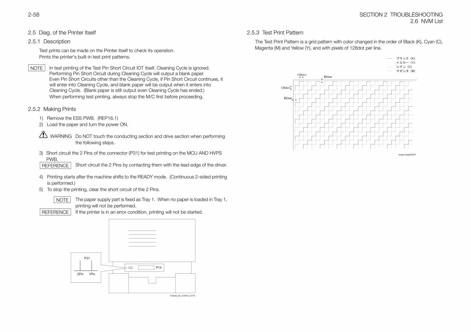
SECTION 2 TROUBLESHOOTING2.6 NVM List
2-58
2.5 Diag. of the Printer Itself
2.5.1 Description
Test prints can be made on the Printer itself to check its operation.Prints the printer's built-in test print patterns.
In test printing of the Test Pin Short Circuit IOT itself, Cleaning Cycle is ignored.Performing Pin Short Circuit during Cleaning Cycle will output a blank paper.Even Pin Short Circuits other than the Cleaning Cycle, if Pin Short Circuit continues, itwill enter into Cleaning Cycle, and blank paper will be output when it enters intoCleaning Cycle. (Blank paper is still output even Cleaning Cycle has ended.)When performing test printing, always stop the M/C first before proceeding.
2.5.2 Making Prints
1) Remove the ESS PWB. (REP16.1)2) Load the paper and turn the power ON.
WARNING Do NOT touch the conducting section and drive section when performingthe following steps.
3) Short circuit the 2 Pins of the connector (P31) for test printing on the MCU AND HVPSPWB.
Short circuit the 2 Pins by contacting them with the lead edge of the driver.
4) Printing starts after the machine shifts to the READY mode. (Continuous 2-sided printingis performed.)
5) To stop the printing, clear the short circuit of the 2 Pins.
The paper supply part is fixed as Tray 1. When no paper is loaded in Tray 1,printing will not be performed.If the printer is in an error condition, printing will not be started.
2.5.3 Test Print Pattern
The Test Print Pattern is a grid pattern with color changed in the order of Black (K), Cyan (C),Magenta (M) and Yellow (Y), and with pixels of 128dot per line.
engine diag0002FA
NOTE
REFERENCE
REFERENCE
NOTE
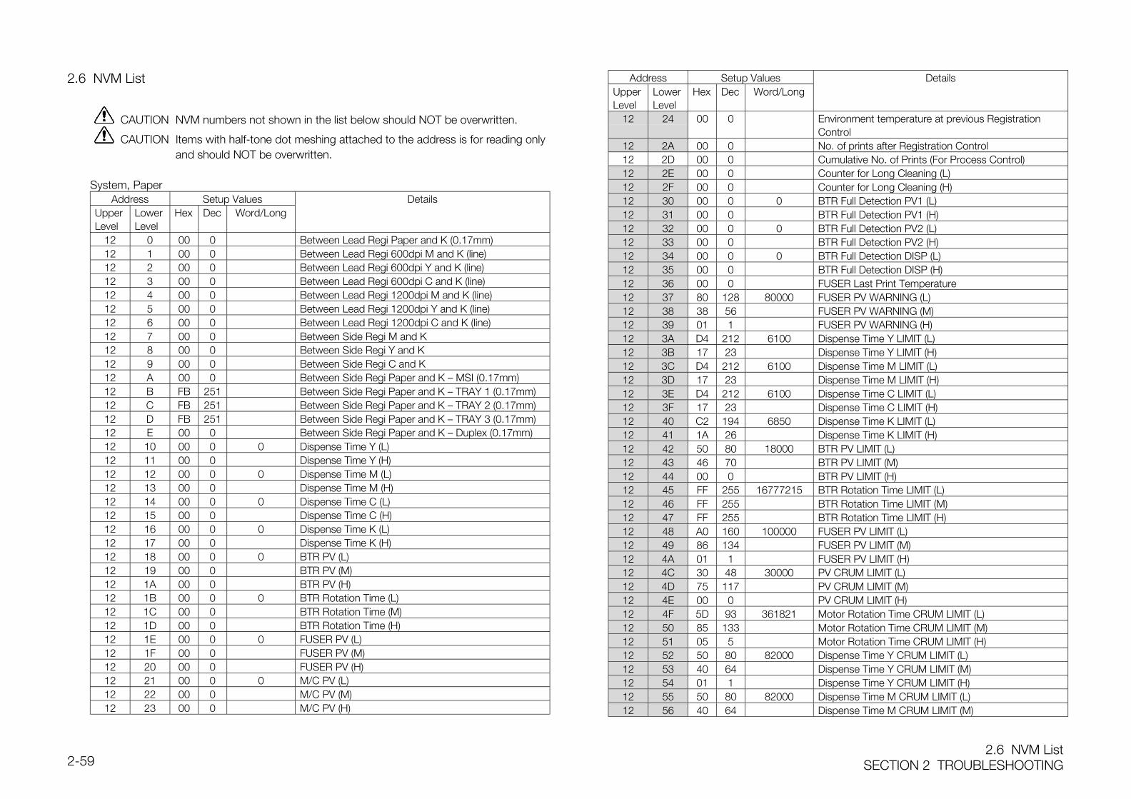
2.6 NVM ListSECTION 2 TROUBLESHOOTING2-59
2.6 NVM List
CAUTION NVM numbers not shown in the list below should NOT be overwritten.
CAUTION Items with half-tone dot meshing attached to the address is for reading onlyand should NOT be overwritten.
System, PaperAddress Setup Values Details
UpperLevel
LowerLevel
Hex Dec Word/Long
12 0 00 0 Between Lead Regi Paper and K (0.17mm)12 1 00 0 Between Lead Regi 600dpi M and K (line)12 2 00 0 Between Lead Regi 600dpi Y and K (line)12 3 00 0 Between Lead Regi 600dpi C and K (line)12 4 00 0 Between Lead Regi 1200dpi M and K (line)12 5 00 0 Between Lead Regi 1200dpi Y and K (line)12 6 00 0 Between Lead Regi 1200dpi C and K (line)12 7 00 0 Between Side Regi M and K12 8 00 0 Between Side Regi Y and K12 9 00 0 Between Side Regi C and K12 A 00 0 Between Side Regi Paper and K — MSI (0.17mm)12 B FB 251 Between Side Regi Paper and K — TRAY 1 (0.17mm)12 C FB 251 Between Side Regi Paper and K — TRAY 2 (0.17mm)12 D FB 251 Between Side Regi Paper and K — TRAY 3 (0.17mm)12 E 00 0 Between Side Regi Paper and K — Duplex (0.17mm)12 10 00 0 0 Dispense Time Y (L)12 11 00 0 Dispense Time Y (H)12 12 00 0 0 Dispense Time M (L)12 13 00 0 Dispense Time M (H)12 14 00 0 0 Dispense Time C (L)12 15 00 0 Dispense Time C (H)12 16 00 0 0 Dispense Time K (L)12 17 00 0 Dispense Time K (H)12 18 00 0 0 BTR PV (L)12 19 00 0 BTR PV (M)12 1A 00 0 BTR PV (H)12 1B 00 0 0 BTR Rotation Time (L)12 1C 00 0 BTR Rotation Time (M)12 1D 00 0 BTR Rotation Time (H)12 1E 00 0 0 FUSER PV (L)12 1F 00 0 FUSER PV (M)12 20 00 0 FUSER PV (H)12 21 00 0 0 M/C PV (L)12 22 00 0 M/C PV (M)12 23 00 0 M/C PV (H)
Address Setup Values DetailsUpperLevel
LowerLevel
Hex Dec Word/Long
12 24 00 0 Environment temperature at previous RegistrationControl
12 2A 00 0 No. of prints after Registration Control12 2D 00 0 Cumulative No. of Prints (For Process Control)12 2E 00 0 Counter for Long Cleaning (L)12 2F 00 0 Counter for Long Cleaning (H)12 30 00 0 0 BTR Full Detection PV1 (L)12 31 00 0 BTR Full Detection PV1 (H)12 32 00 0 0 BTR Full Detection PV2 (L)12 33 00 0 BTR Full Detection PV2 (H)12 34 00 0 0 BTR Full Detection DISP (L)12 35 00 0 BTR Full Detection DISP (H)12 36 00 0 FUSER Last Print Temperature12 37 80 128 80000 FUSER PV WARNING (L)12 38 38 56 FUSER PV WARNING (M)12 39 01 1 FUSER PV WARNING (H)12 3A D4 212 6100 Dispense Time Y LIMIT (L)12 3B 17 23 Dispense Time Y LIMIT (H)12 3C D4 212 6100 Dispense Time M LIMIT (L)12 3D 17 23 Dispense Time M LIMIT (H)12 3E D4 212 6100 Dispense Time C LIMIT (L)12 3F 17 23 Dispense Time C LIMIT (H)12 40 C2 194 6850 Dispense Time K LIMIT (L)12 41 1A 26 Dispense Time K LIMIT (H)12 42 50 80 18000 BTR PV LIMIT (L)12 43 46 70 BTR PV LIMIT (M)12 44 00 0 BTR PV LIMIT (H)12 45 FF 255 16777215 BTR Rotation Time LIMIT (L)12 46 FF 255 BTR Rotation Time LIMIT (M)12 47 FF 255 BTR Rotation Time LIMIT (H)12 48 A0 160 100000 FUSER PV LIMIT (L)12 49 86 134 FUSER PV LIMIT (M)12 4A 01 1 FUSER PV LIMIT (H)12 4C 30 48 30000 PV CRUM LIMIT (L)12 4D 75 117 PV CRUM LIMIT (M)12 4E 00 0 PV CRUM LIMIT (H)12 4F 5D 93 361821 Motor Rotation Time CRUM LIMIT (L)12 50 85 133 Motor Rotation Time CRUM LIMIT (M)12 51 05 5 Motor Rotation Time CRUM LIMIT (H)12 52 50 80 82000 Dispense Time Y CRUM LIMIT (L)12 53 40 64 Dispense Time Y CRUM LIMIT (M)12 54 01 1 Dispense Time Y CRUM LIMIT (H)12 55 50 80 82000 Dispense Time M CRUM LIMIT (L)12 56 40 64 Dispense Time M CRUM LIMIT (M)
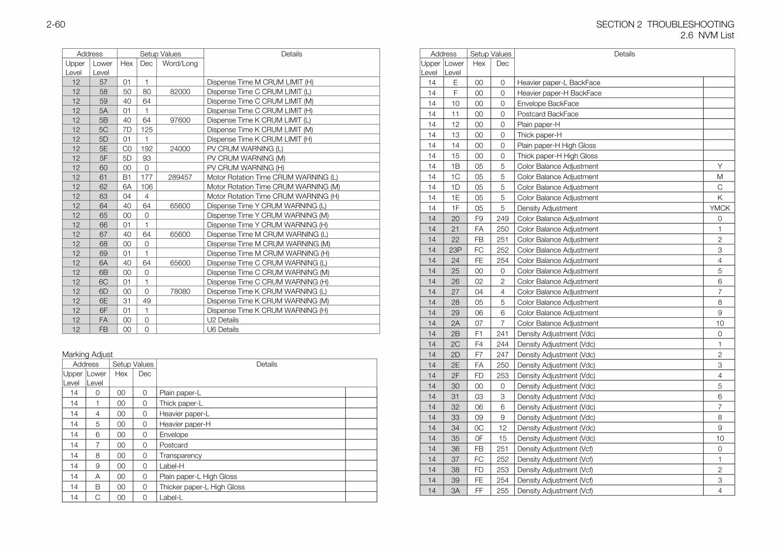
SECTION 2 TROUBLESHOOTING2.6 NVM List
2-60
Address Setup Values DetailsUpperLevel
LowerLevel
Hex Dec Word/Long
12 57 01 1 Dispense Time M CRUM LIMIT (H)12 58 50 80 82000 Dispense Time C CRUM LIMIT (L)12 59 40 64 Dispense Time C CRUM LIMIT (M)12 5A 01 1 Dispense Time C CRUM LIMIT (H)12 5B 40 64 97600 Dispense Time K CRUM LIMIT (L)12 5C 7D 125 Dispense Time K CRUM LIMIT (M)12 5D 01 1 Dispense Time K CRUM LIMIT (H)12 5E C0 192 24000 PV CRUM WARNING (L)12 5F 5D 93 PV CRUM WARNING (M)12 60 00 0 PV CRUM WARNING (H)12 61 B1 177 289457 Motor Rotation Time CRUM WARNING (L)12 62 6A 106 Motor Rotation Time CRUM WARNING (M)12 63 04 4 Motor Rotation Time CRUM WARNING (H)12 64 40 64 65600 Dispense Time Y CRUM WARNING (L)12 65 00 0 Dispense Time Y CRUM WARNING (M)12 66 01 1 Dispense Time Y CRUM WARNING (H)12 67 40 64 65600 Dispense Time M CRUM WARNING (L)12 68 00 0 Dispense Time M CRUM WARNING (M)12 69 01 1 Dispense Time M CRUM WARNING (H)12 6A 40 64 65600 Dispense Time C CRUM WARNING (L)12 6B 00 0 Dispense Time C CRUM WARNING (M)12 6C 01 1 Dispense Time C CRUM WARNING (H)12 6D 00 0 78080 Dispense Time K CRUM WARNING (L)12 6E 31 49 Dispense Time K CRUM WARNING (M)12 6F 01 1 Dispense Time K CRUM WARNING (H)12 FA 00 0 U2 Details12 FB 00 0 U6 Details
Marking AdjustAddress Setup Values Details
UpperLevel
LowerLevel
Hex Dec
14 0 00 0 Plain paper-L14 1 00 0 Thick paper-L14 4 00 0 Heavier paper-L14 5 00 0 Heavier paper-H14 6 00 0 Envelope14 7 00 0 Postcard14 8 00 0 Transparency14 9 00 0 Label-H14 A 00 0 Plain paper-L High Gloss14 B 00 0 Thicker paper-L High Gloss14 C 00 0 Label-L
Address Setup Values DetailsUpperLevel
LowerLevel
Hex Dec
14 E 00 0 Heavier paper-L BackFace14 F 00 0 Heavier paper-H BackFace14 10 00 0 Envelope BackFace14 11 00 0 Postcard BackFace14 12 00 0 Plain paper-H14 13 00 0 Thick paper-H14 14 00 0 Plain paper-H High Gloss14 15 00 0 Thick paper-H High Gloss14 1B 05 5 Color Balance Adjustment Y14 1C 05 5 Color Balance Adjustment M14 1D 05 5 Color Balance Adjustment C14 1E 05 5 Color Balance Adjustment K14 1F 05 5 Density Adjustment YMCK14 20 F9 249 Color Balance Adjustment 014 21 FA 250 Color Balance Adjustment 114 22 FB 251 Color Balance Adjustment 214 23P FC 252 Color Balance Adjustment 314 24 FE 254 Color Balance Adjustment 414 25 00 0 Color Balance Adjustment 514 26 02 2 Color Balance Adjustment 614 27 04 4 Color Balance Adjustment 714 28 05 5 Color Balance Adjustment 814 29 06 6 Color Balance Adjustment 914 2A 07 7 Color Balance Adjustment 1014 2B F1 241 Density Adjustment (Vdc) 014 2C F4 244 Density Adjustment (Vdc) 114 2D F7 247 Density Adjustment (Vdc) 214 2E FA 250 Density Adjustment (Vdc) 314 2F FD 253 Density Adjustment (Vdc) 414 30 00 0 Density Adjustment (Vdc) 514 31 03 3 Density Adjustment (Vdc) 614 32 06 6 Density Adjustment (Vdc) 714 33 09 9 Density Adjustment (Vdc) 814 34 0C 12 Density Adjustment (Vdc) 914 35 0F 15 Density Adjustment (Vdc) 1014 36 FB 251 Density Adjustment (Vcf) 014 37 FC 252 Density Adjustment (Vcf) 114 38 FD 253 Density Adjustment (Vcf) 214 39 FE 254 Density Adjustment (Vcf) 314 3A FF 255 Density Adjustment (Vcf) 4
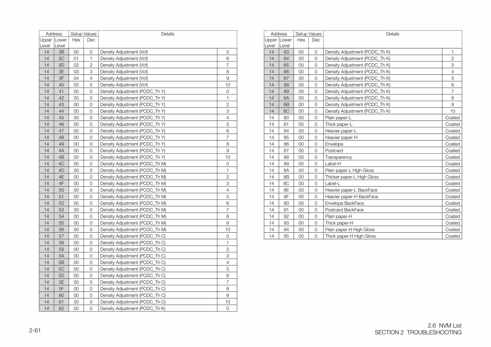
2.6 NVM ListSECTION 2 TROUBLESHOOTING2-61
Address Setup Values DetailsUpperLevel
LowerLevel
Hex Dec
14 3B 00 0 Density Adjustment (Vcf) 514 3C 01 1 Density Adjustment (Vcf) 614 3D 02 2 Density Adjustment (Vcf) 714 3E 03 3 Density Adjustment (Vcf) 814 3F 04 4 Density Adjustment (Vcf) 914 40 05 5 Density Adjustment (Vcf) 1014 41 00 0 Density Adjustment (PCDC_Th Y) 014 42 00 0 Density Adjustment (PCDC_Th Y) 114 43 00 0 Density Adjustment (PCDC_Th Y) 214 44 00 0 Density Adjustment (PCDC_Th Y) 314 45 00 0 Density Adjustment (PCDC_Th Y) 414 46 00 0 Density Adjustment (PCDC_Th Y) 514 47 00 0 Density Adjustment (PCDC_Th Y) 614 48 00 0 Density Adjustment (PCDC_Th Y) 714 49 00 0 Density Adjustment (PCDC_Th Y) 814 4A 00 0 Density Adjustment (PCDC_Th Y) 914 4B 00 0 Density Adjustment (PCDC_Th Y) 1014 4C 00 0 Density Adjustment (PCDC_Th M) 014 4D 00 0 Density Adjustment (PCDC_Th M) 114 4E 00 0 Density Adjustment (PCDC_Th M) 214 4F 00 0 Density Adjustment (PCDC_Th M) 314 50 00 0 Density Adjustment (PCDC_Th M) 414 51 00 0 Density Adjustment (PCDC_Th M) 514 52 00 0 Density Adjustment (PCDC_Th M) 614 53 00 0 Density Adjustment (PCDC_Th M) 714 54 00 0 Density Adjustment (PCDC_Th M) 814 55 00 0 Density Adjustment (PCDC_Th M) 914 56 00 0 Density Adjustment (PCDC_Th M) 1014 57 00 0 Density Adjustment (PCDC_Th C) 014 58 00 0 Density Adjustment (PCDC_Th C) 114 59 00 0 Density Adjustment (PCDC_Th C) 214 5A 00 0 Density Adjustment (PCDC_Th C) 314 5B 00 0 Density Adjustment (PCDC_Th C) 414 5C 00 0 Density Adjustment (PCDC_Th C) 514 5D 00 0 Density Adjustment (PCDC_Th C) 614 5E 00 0 Density Adjustment (PCDC_Th C) 714 5F 00 0 Density Adjustment (PCDC_Th C) 814 60 00 0 Density Adjustment (PCDC_Th C) 914 61 00 0 Density Adjustment (PCDC_Th C) 1014 62 00 0 Density Adjustment (PCDC_Th K) 0
Address Setup Values DetailsUpperLevel
LowerLevel
Hex Dec
14 63 00 0 Density Adjustment (PCDC_Th K) 114 64 00 0 Density Adjustment (PCDC_Th K) 214 65 00 0 Density Adjustment (PCDC_Th K) 314 66 00 0 Density Adjustment (PCDC_Th K) 414 67 00 0 Density Adjustment (PCDC_Th K) 514 68 00 0 Density Adjustment (PCDC_Th K) 614 69 00 0 Density Adjustment (PCDC_Th K) 714 6A 00 0 Density Adjustment (PCDC_Th K) 814 6B 00 0 Density Adjustment (PCDC_Th K) 914 6C 00 0 Density Adjustment (PCDC_Th K) 1014 80 00 0 Plain paper-L Coated14 81 00 0 Thick paper-L Coated14 84 00 0 Heavier paper-L Coated14 85 00 0 Heavier paper-H Coated14 86 00 0 Envelope Coated14 87 00 0 Postcard Coated14 88 00 0 Transparency Coated14 89 00 0 Label-H Coated14 8A 00 0 Plain paper-L High Gloss Coated14 8B 00 0 Thicker paper-L High Gloss Coated14 8C 00 0 Label-L Coated14 8E 00 0 Heavier paper-L BackFace Coated14 8F 00 0 Heavier paper-H BackFace Coated14 90 00 0 Envelope BackFace Coated14 91 00 0 Postcard BackFace Coated14 92 00 0 Plain paper-H Coated14 93 00 0 Thick paper-H Coated14 94 00 0 Plain paper-H High Gloss Coated14 95 00 0 Thick paper-H High Gloss Coated
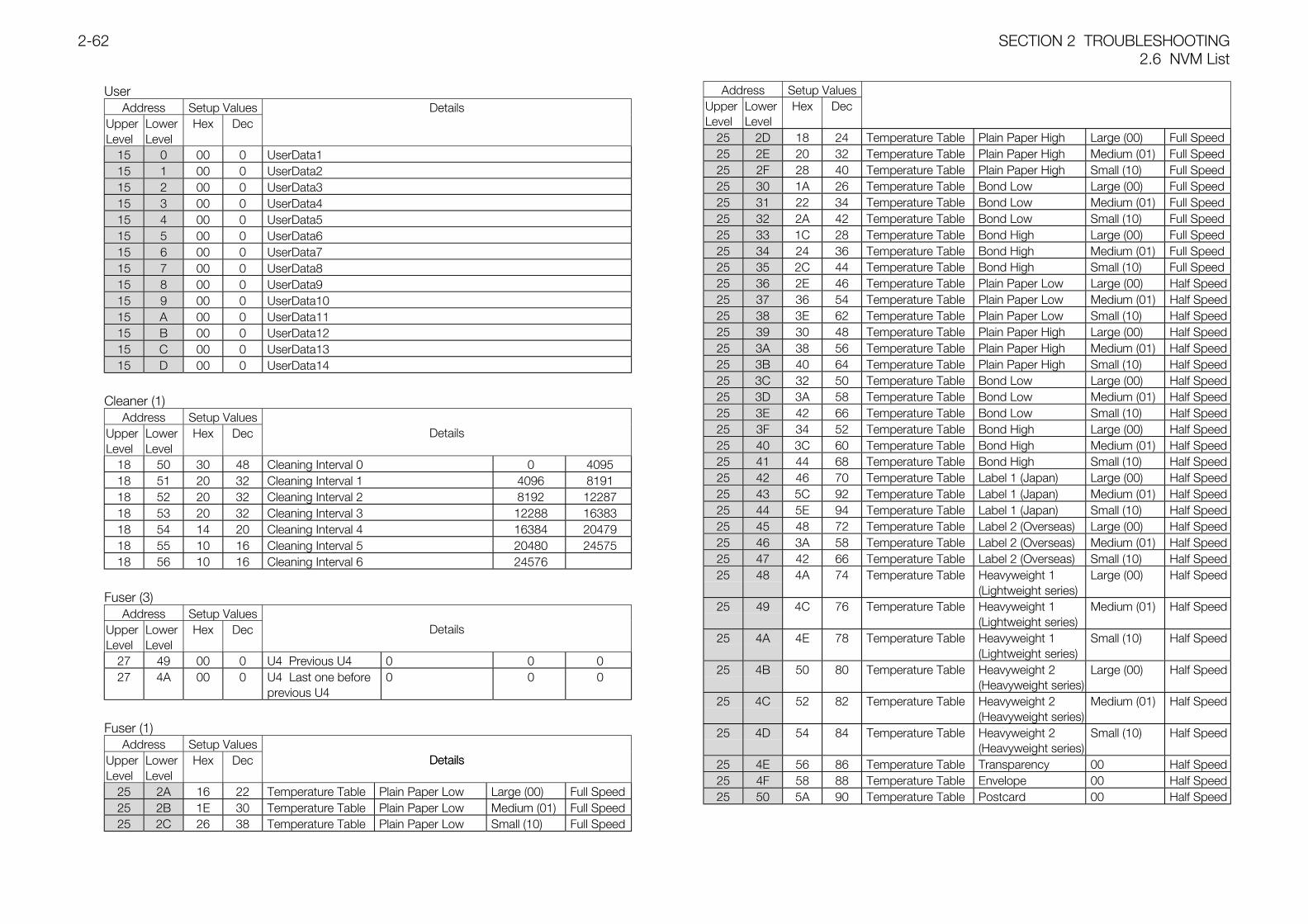
SECTION 2 TROUBLESHOOTING2.6 NVM List
2-62
UserAddress Setup Values Details
UpperLevel
LowerLevel
Hex Dec
15 0 00 0 UserData115 1 00 0 UserData215 2 00 0 UserData315 3 00 0 UserData415 4 00 0 UserData515 5 00 0 UserData615 6 00 0 UserData715 7 00 0 UserData815 8 00 0 UserData915 9 00 0 UserData1015 A 00 0 UserData1115 B 00 0 UserData1215 C 00 0 UserData1315 D 00 0 UserData14
Cleaner (1)Address Setup Values
UpperLevel
LowerLevel
Hex Dec Details
18 50 30 48 Cleaning Interval 0 0 409518 51 20 32 Cleaning Interval 1 4096 819118 52 20 32 Cleaning Interval 2 8192 1228718 53 20 32 Cleaning Interval 3 12288 1638318 54 14 20 Cleaning Interval 4 16384 2047918 55 10 16 Cleaning Interval 5 20480 2457518 56 10 16 Cleaning Interval 6 24576
Fuser (3)Address Setup Values
UpperLevel
LowerLevel
Hex Dec Details
27 49 00 0 U4 Previous U4 0 0 027 4A 00 0 U4 Last one before
previous U40 0 0
Fuser (1)Address Setup Values
UpperLevel
LowerLevel
Hex Dec Details
25 2A 16 22 Temperature Table Plain Paper Low Large (00) Full Speed25 2B 1E 30 Temperature Table Plain Paper Low Medium (01) Full Speed25 2C 26 38 Temperature Table Plain Paper Low Small (10) Full Speed
Address Setup ValuesUpperLevel
LowerLevel
Hex Dec
Details
25 2D 18 24 Temperature Table Plain Paper High Large (00) Full Speed25 2E 20 32 Temperature Table Plain Paper High Medium (01) Full Speed25 2F 28 40 Temperature Table Plain Paper High Small (10) Full Speed25 30 1A 26 Temperature Table Bond Low Large (00) Full Speed25 31 22 34 Temperature Table Bond Low Medium (01) Full Speed25 32 2A 42 Temperature Table Bond Low Small (10) Full Speed25 33 1C 28 Temperature Table Bond High Large (00) Full Speed25 34 24 36 Temperature Table Bond High Medium (01) Full Speed25 35 2C 44 Temperature Table Bond High Small (10) Full Speed25 36 2E 46 Temperature Table Plain Paper Low Large (00) Half Speed25 37 36 54 Temperature Table Plain Paper Low Medium (01) Half Speed25 38 3E 62 Temperature Table Plain Paper Low Small (10) Half Speed25 39 30 48 Temperature Table Plain Paper High Large (00) Half Speed25 3A 38 56 Temperature Table Plain Paper High Medium (01) Half Speed25 3B 40 64 Temperature Table Plain Paper High Small (10) Half Speed25 3C 32 50 Temperature Table Bond Low Large (00) Half Speed25 3D 3A 58 Temperature Table Bond Low Medium (01) Half Speed25 3E 42 66 Temperature Table Bond Low Small (10) Half Speed25 3F 34 52 Temperature Table Bond High Large (00) Half Speed25 40 3C 60 Temperature Table Bond High Medium (01) Half Speed25 41 44 68 Temperature Table Bond High Small (10) Half Speed25 42 46 70 Temperature Table Label 1 (Japan) Large (00) Half Speed25 43 5C 92 Temperature Table Label 1 (Japan) Medium (01) Half Speed25 44 5E 94 Temperature Table Label 1 (Japan) Small (10) Half Speed25 45 48 72 Temperature Table Label 2 (Overseas) Large (00) Half Speed25 46 3A 58 Temperature Table Label 2 (Overseas) Medium (01) Half Speed25 47 42 66 Temperature Table Label 2 (Overseas) Small (10) Half Speed25 48 4A 74 Temperature Table Heavyweight 1
(Lightweight series)Large (00) Half Speed
25 49 4C 76 Temperature Table Heavyweight 1(Lightweight series)
Medium (01) Half Speed
25 4A 4E 78 Temperature Table Heavyweight 1(Lightweight series)
Small (10) Half Speed
25 4B 50 80 Temperature Table Heavyweight 2(Heavyweight series)
Large (00) Half Speed
25 4C 52 82 Temperature Table Heavyweight 2(Heavyweight series)
Medium (01) Half Speed
25 4D 54 84 Temperature Table Heavyweight 2(Heavyweight series)
Small (10) Half Speed
25 4E 56 86 Temperature Table Transparency 00 Half Speed25 4F 58 88 Temperature Table Envelope 00 Half Speed25 50 5A 90 Temperature Table Postcard 00 Half Speed
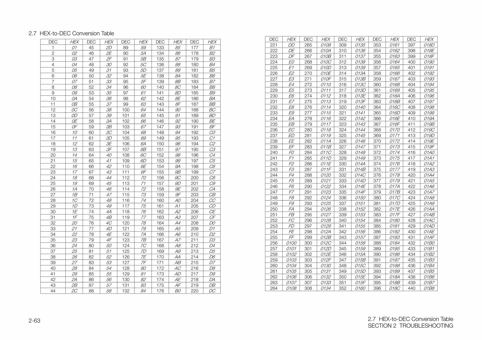
2.7 HEX-to-DEC Conversion TableSECTION 2 TROUBLESHOOTING
2-63
2.7 HEX-to-DEC Conversion TableDEC HEX DEC HEX DEC HEX DEC HEX DEC HEX
1 01 45 2D 89 59 133 85 177 B12 02 46 2E 90 5A 134 86 178 B23 03 47 2F 91 5B 135 87 179 B34 04 48 30 92 5C 136 88 180 B45 05 49 31 93 5D 137 89 181 B56 06 50 32 94 5E 138 8A 182 B67 07 51 33 95 5F 139 8B 183 B78 08 52 34 96 60 140 8C 184 B89 09 53 35 97 61 141 8D 185 B9
10 0A 54 36 98 62 142 8E 186 BA11 0B 55 37 99 63 143 8F 187 BB12 0C 56 38 100 64 144 90 188 BC13 0D 57 39 101 65 145 91 189 BD14 0E 58 3A 102 66 146 92 190 BE15 0F 59 3B 103 67 147 93 191 BF16 10 60 3C 104 68 148 94 192 C017 11 61 3D 105 69 149 95 193 C118 12 62 3E 106 6A 150 96 194 C219 13 63 3F 107 6B 151 97 195 C320 14 64 40 108 6C 152 98 196 C421 15 65 41 109 6D 153 99 197 C522 16 66 42 110 6E 154 9A 198 C623 17 67 43 111 6F 155 9B 199 C724 18 68 44 112 70 156 9C 200 C825 19 69 45 113 71 157 9D 201 C926 1A 70 46 114 72 158 9E 202 CA27 1B 71 47 115 73 159 9F 203 CB28 1C 72 48 116 74 160 A0 204 CC29 1D 73 49 117 75 161 A1 205 CD30 1E 74 4A 118 76 162 A2 206 CE31 1F 75 4B 119 77 163 A3 207 CF32 20 76 4C 120 78 164 A4 208 D033 21 77 4D 121 79 165 A5 209 D134 22 78 4E 122 7A 166 A6 210 D235 23 79 4F 123 7B 167 A7 211 D336 24 80 50 124 7C 168 A8 212 D437 25 81 51 125 7D 169 A9 213 D538 26 82 52 126 7E 170 AA 214 D639 27 83 53 127 7F 171 AB 215 D740 28 84 54 128 80 172 AC 216 D841 29 85 55 129 81 173 AD 217 D942 2A 86 56 130 82 174 AE 218 DA43 2B 87 57 131 83 175 AF 219 DB44 2C 88 58 132 84 176 B0 220 DC
DEC HEX DEC HEX DEC HEX DEC HEX DEC HEX221 DD 265 0109 309 0135 353 0161 397 018D222 DE 266 010A 310 0136 354 0162 398 018E223 DF 267 010B 311 0137 355 0163 399 018F224 E0 268 010C 312 0138 356 0164 400 0190225 E1 269 010D 313 0139 357 0165 401 0191226 E2 270 010E 314 013A 358 0166 402 0192227 E3 271 010F 315 013B 359 0167 403 0193228 E4 272 0110 316 013C 360 0168 404 0194229 E5 273 0111 317 013D 361 0169 405 0195230 E6 274 0112 318 013E 362 016A 406 0196231 E7 275 0113 319 013F 363 016B 407 0197232 E8 276 0114 320 0140 364 016C 408 0198233 E9 277 0115 321 0141 365 016D 409 0199234 EA 278 0116 322 0142 366 016E 410 019A235 EB 279 0117 323 0143 367 016F 411 019B236 EC 280 0118 324 0144 368 0170 412 019C237 ED 281 0119 325 0145 369 0171 413 019D238 EE 282 011A 326 0146 370 0172 414 019E239 EF 283 011B 327 0147 371 0173 415 019F240 F0 284 011C 328 0148 372 0174 416 01A0241 F1 285 011D 329 0149 373 0175 417 01A1242 F2 286 011E 330 014A 374 0176 418 01A2243 F3 287 011F 331 014B 375 0177 419 01A3244 F4 288 0120 332 014C 376 0178 420 01A4245 F5 289 0121 333 014D 377 0179 421 01A5246 F6 290 0122 334 014E 378 017A 422 01A6247 F7 291 0123 335 014F 379 017B 423 01A7248 F8 292 0124 336 0150 380 017C 424 01A8249 F9 293 0125 337 0151 381 017D 425 01A9250 FA 294 0126 338 0152 382 017E 426 01AA251 FB 295 0127 339 0153 383 017F 427 01AB252 FC 296 0128 340 0154 384 0180 428 01AC253 FD 297 0129 341 0155 385 0181 429 01AD254 FE 298 012A 342 0156 386 0182 430 01AE255 FF 299 012B 343 0157 387 0183 431 01AF256 0100 300 012C 344 0158 388 0184 432 01B0257 0101 301 012D 345 0159 389 0185 433 01B1258 0102 302 012E 346 015A 390 0186 434 01B2259 0103 303 012F 347 015B 391 0187 435 01B3260 0104 304 0130 348 015C 392 0188 436 01B4261 0105 305 0131 349 015D 393 0189 437 01B5262 0106 306 0132 350 015E 394 018A 438 01B6263 0107 307 0133 351 015F 395 018B 439 01B7264 0108 308 0134 352 0160 396 018C 440 01B8

SECTION 3 IMAGE QUALITY TROUBLESHOOTING
ContentsSECTION 3 IMAGE QUALITY TROUBLESHOOTING3-1
Contents
3.1 Image Quality Troubleshooting Flowchart ........................................................... 2
3.2 Image Specifications.......................................................................................... 3
3.2.1 Parallelism ................................................................................................... 3
3.2.2 Perpendicularity ........................................................................................... 3
3.2.3 Skew ........................................................................................................... 3
3.2.4 Linearity....................................................................................................... 3
3.2.5 Magnification Error ....................................................................................... 4
3.2.6 Registration ................................................................................................. 4
3.2.7 Guaranteed Print Area ................................................................................. 4
3.3 Test Print ........................................................................................................... 5
3.3.1 Test Print ..................................................................................................... 5
3.4 Image Quality FIP............................................................................................... 6
3.4.1 Precautions for Image Quality Troubleshooting ............................................. 6
3.4.2 Basic Rules for Image Quality Adjustment .................................................... 6
3.4.3 Symptoms vs Image Quality Problems ......................................................... 7
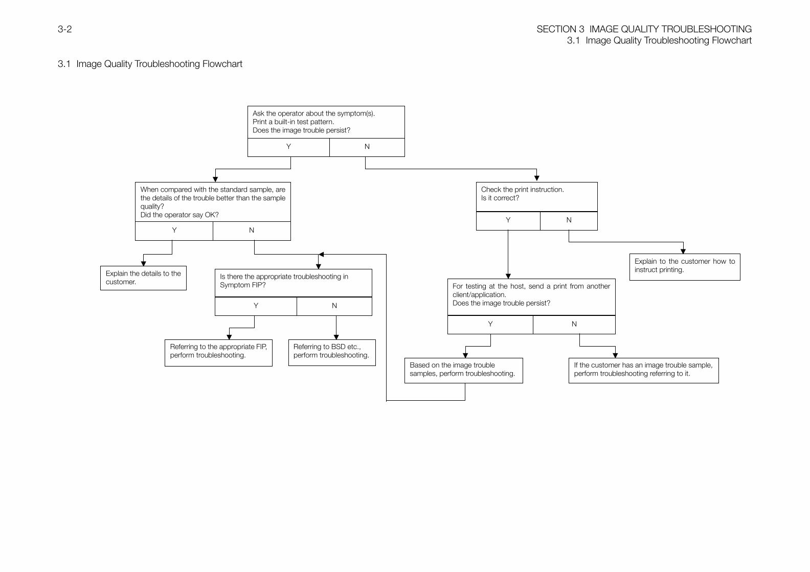
SECTION 3 IMAGE QUALITY TROUBLESHOOTING3.1 Image Quality Troubleshooting Flowchart
3-2
3.1 Image Quality Troubleshooting Flowchart
Ask the operator about the symptom(s).Print a built-in test pattern.Does the image trouble persist?
Y N
When compared with the standard sample, arethe details of the trouble better than the samplequality?Did the operator say OK?
Check the print instruction.Is it correct?
Y N
Explain to the customer how toinstruct printing.
For testing at the host, send a print from anotherclient/application.Does the image trouble persist?
Y N
If the customer has an image trouble sample,perform troubleshooting referring to it.
Y N
Explain the details to thecustomer.
Is there the appropriate troubleshooting inSymptom FIP?
Y N
Referring to the appropriate FIP,perform troubleshooting.
Based on the image troublesamples, perform troubleshooting.
Referring to BSD etc.,perform troubleshooting.
3.2 Image SpecificationsSECTION 3 IMAGE QUALITY TROUBLESHOOTING3-3
3.2 Image Specifications
3.2.1 Parallelism
3.2.2 Perpendicularity
3.2.3 Skew
3.2.4 Linearity
SECTION 3 IMAGE QUALITY TROUBLESHOOTING3.2 Image Specifications
3-4
3.2.5 Magnification Error
3.2.6 Registration
3.2.7 Guaranteed Print Area
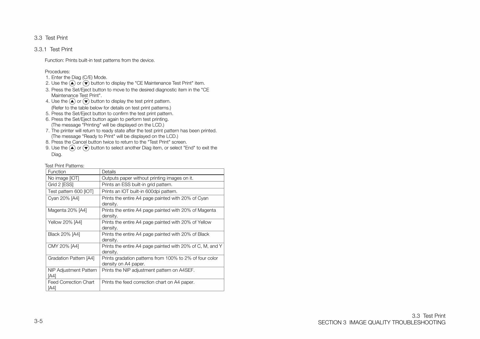
3.3 Test PrintSECTION 3 IMAGE QUALITY TROUBLESHOOTING3-5
3.3 Test Print
3.3.1 Test Print
Function: Prints built-in test patterns from the device.
Procedures:1. Enter the Diag (C/E) Mode.2. Use the or button to display the "CE Maintenance Test Print" item.3. Press the Set/Eject button to move to the desired diagnostic item in the "CE
Maintenance Test Print".4. Use the or button to display the test print pattern.
(Refer to the table below for details on test print patterns.)5. Press the Set/Eject button to confirm the test print pattern.6. Press the Set/Eject button again to perform test printing.
(The message "Printing" will be displayed on the LCD.)7. The printer will return to ready state after the test print pattern has been printed.
(The message "Ready to Print" will be displayed on the LCD.)8. Press the Cancel button twice to return to the "Test Print" screen.9. Use the or button to select another Diag item, or select "End" to exit the
Diag.
Test Print Patterns:Function DetailsNo image [IOT] Outputs paper without printing images on it.Grid 2 [ESS] Prints an ESS built-in grid pattern.Test pattern 600 [IOT] Prints an IOT built-in 600dpi pattern.Cyan 20% [A4] Prints the entire A4 page painted with 20% of Cyan
density.Magenta 20% [A4] Prints the entire A4 page painted with 20% of Magenta
density.Yellow 20% [A4] Prints the entire A4 page painted with 20% of Yellow
density.Black 20% [A4] Prints the entire A4 page painted with 20% of Black
density.CMY 20% [A4] Prints the entire A4 page painted with 20% of C, M, and Y
density.Gradation Pattern [A4] Prints gradation patterns from 100% to 2% of four color
density on A4 paper.NIP Adjustment Pattern[A4]
Prints the NIP adjustment pattern on A4SEF.
Feed Correction Chart[A4]
Prints the feed correction chart on A4 paper.
!"
# $%&'()&$ $&*(+&&'
+ %+%,' '- +'-' &) . $&*(+&&' (+&- * -&'
%%&$-'&+(&)$&*(+&&'(/(*(-&'-))$'(/&()'
. )$ &$ *'&$ . &%%$( $/-0 %+%, +
%(&$1('(&''2$&''0(--&%'('-+)&)%&'(*(
#'(&''2$&''
'($++/&3$(//2&(#44±#45 2&-/%(3+++ /$$&$+++- 6'$3$ )%(03$
+$(0+-)$(0$%&'-&'$(&$(&$%(&)'&'7'--(/%(
2&-/%(3+$&'((-
2&--$%('+
2&-/&&$2'-/%(
2&-/%(3+$+/$'$%''&*,/2
8+%,+)&$ /$&*(
+%,)+/$&*-/'-(&'+//%&'(-&/$)&$+/$'
&/
#7 $')$&'&+$%'
87 $')$&'&+$//%&'
7 $')$&'&+$)
7 /%+-$2$
97 /%+//%&'
"7 +%,+%'((
+%,&'(*(
+%,+)&)%&'(*(
#7 :$$$- 4;/$'(
8 $'()$&$$- #<;/$'(
7 &'$$$- ";/$'(
7 &'$$$- ";/$'(
97 &'$$$- ";/$'(
" ;&'$$$- <;/$'(
8(%()&$ -=('
+*(% $( )&$ .-=(' $ &%'+%&/&''(&) +
/$'$
'+%&/&''(&)+:'(&$0//$)-$0)($'-$'()$&
&%*($(&$($(-'(+&$/$&-&)&''%&/&''&)
+ /$'$ %&- * %(- * + '(&' '2$&'' () +$)&$0
//$&/$%&'(+&-*,'
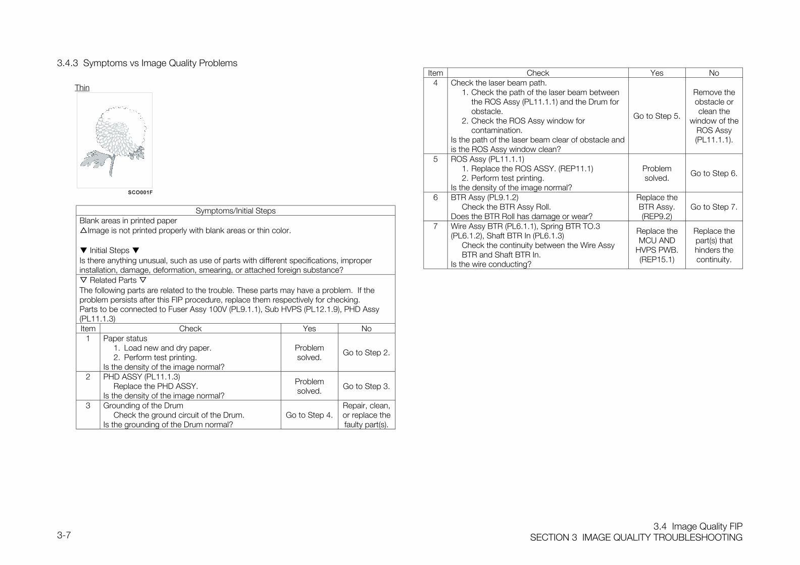
3.4 Image Quality FIPSECTION 3 IMAGE QUALITY TROUBLESHOOTING3-7
3.4.3 Symptoms vs Image Quality Problems
Thin
Symptoms/Initial StepsBlank areas in printed paperImage is not printed properly with blank areas or thin color.
Initial Steps Is there anything unusual, such as use of parts with different specifications, improperinstallation, damage, deformation, smearing, or attached foreign substance? Related Parts The following parts are related to the trouble. These parts may have a problem. If theproblem persists after this FIP procedure, replace them respectively for checking.Parts to be connected to Fuser Assy 100V (PL9.1.1), Sub HVPS (PL12.1.9), PHD Assy(PL11.1.3)Item Check Yes No
1 Paper status1. Load new and dry paper.2. Perform test printing.
Is the density of the image normal?
Problemsolved.
Go to Step 2.
2 PHD ASSY (PL11.1.3)Replace the PHD ASSY.
Is the density of the image normal?
Problemsolved. Go to Step 3.
3 Grounding of the DrumCheck the ground circuit of the Drum.
Is the grounding of the Drum normal?Go to Step 4.
Repair, clean,or replace thefaulty part(s).
Item Check Yes No4 Check the laser beam path.
1. Check the path of the laser beam betweenthe ROS Assy (PL11.1.1) and the Drum forobstacle.
2. Check the ROS Assy window forcontamination.
Is the path of the laser beam clear of obstacle andis the ROS Assy window clean?
Go to Step 5.
Remove theobstacle orclean the
window of theROS Assy(PL11.1.1).
5 ROS Assy (PL11.1.1)1. Replace the ROS ASSY. (REP11.1)2. Perform test printing.
Is the density of the image normal?
Problemsolved.
Go to Step 6.
6 BTR Assy (PL9.1.2)Check the BTR Assy Roll.
Does the BTR Roll has damage or wear?
Replace theBTR Assy.(REP9.2)
Go to Step 7.
7 Wire Assy BTR (PL6.1.1), Spring BTR TO.3(PL6.1.2), Shaft BTR In (PL6.1.3)
Check the continuity between the Wire AssyBTR and Shaft BTR In.
Is the wire conducting?
Replace theMCU AND
HVPS PWB.(REP15.1)
Replace thepart(s) thathinders thecontinuity.
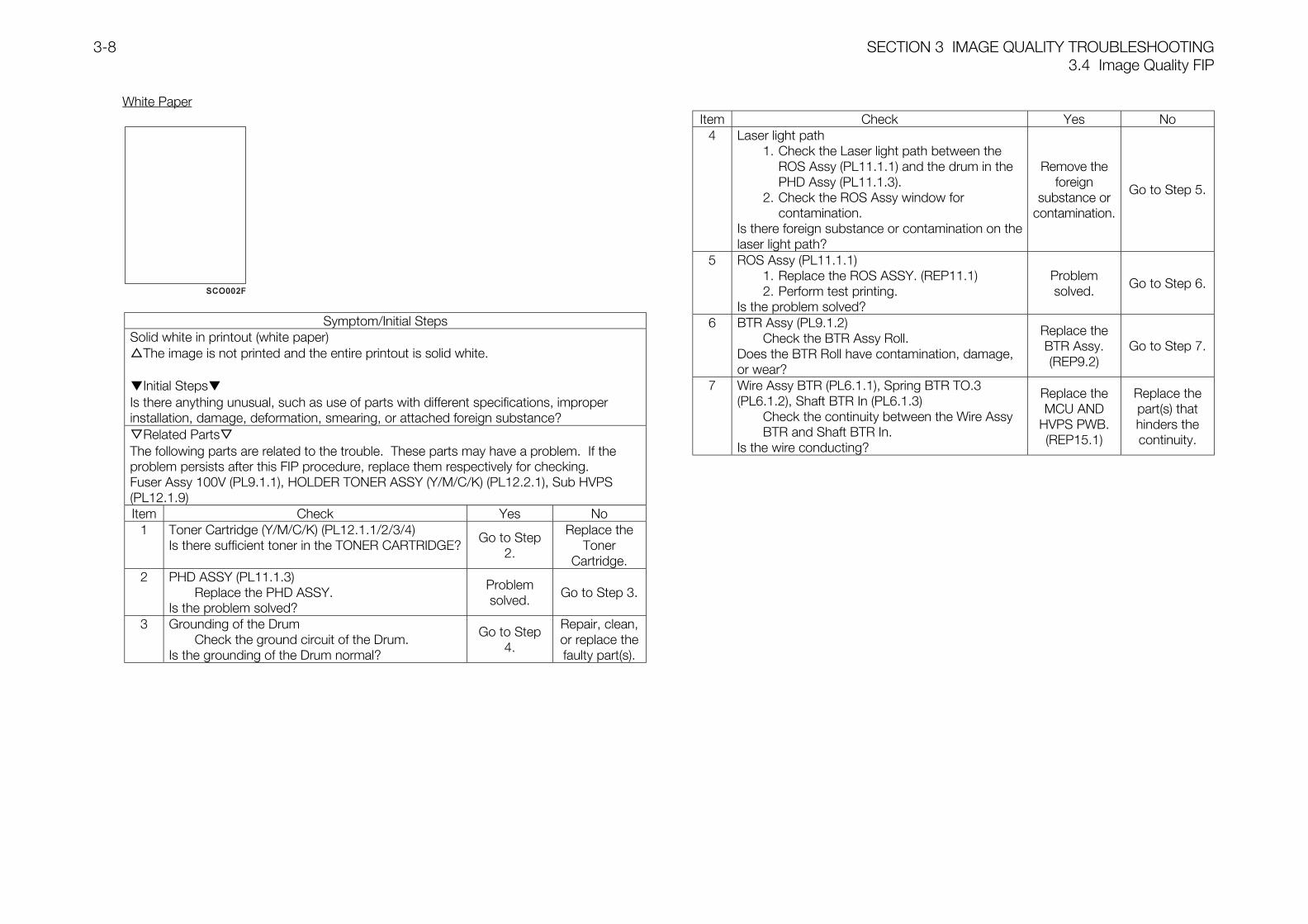
SECTION 3 IMAGE QUALITY TROUBLESHOOTING3.4 Image Quality FIP
3-8
White Paper
Symptom/Initial StepsSolid white in printout (white paper)The image is not printed and the entire printout is solid white.
Initial StepsIs there anything unusual, such as use of parts with different specifications, improperinstallation, damage, deformation, smearing, or attached foreign substance?Related PartsThe following parts are related to the trouble. These parts may have a problem. If theproblem persists after this FIP procedure, replace them respectively for checking.Fuser Assy 100V (PL9.1.1), HOLDER TONER ASSY (Y/M/C/K) (PL12.2.1), Sub HVPS(PL12.1.9)Item Check Yes No
1 Toner Cartridge (Y/M/C/K) (PL12.1.1/2/3/4)Is there sufficient toner in the TONER CARTRIDGE?
Go to Step2.
Replace theToner
Cartridge.2 PHD ASSY (PL11.1.3)
Replace the PHD ASSY.Is the problem solved?
Problemsolved.
Go to Step 3.
3 Grounding of the DrumCheck the ground circuit of the Drum.
Is the grounding of the Drum normal?
Go to Step4.
Repair, clean,or replace thefaulty part(s).
Item Check Yes No4 Laser light path
1. Check the Laser light path between theROS Assy (PL11.1.1) and the drum in thePHD Assy (PL11.1.3).
2. Check the ROS Assy window forcontamination.
Is there foreign substance or contamination on thelaser light path?
Remove theforeign
substance orcontamination.
Go to Step 5.
5 ROS Assy (PL11.1.1)1. Replace the ROS ASSY. (REP11.1)2. Perform test printing.
Is the problem solved?
Problemsolved.
Go to Step 6.
6 BTR Assy (PL9.1.2)Check the BTR Assy Roll.
Does the BTR Roll have contamination, damage,or wear?
Replace theBTR Assy.(REP9.2)
Go to Step 7.
7 Wire Assy BTR (PL6.1.1), Spring BTR TO.3(PL6.1.2), Shaft BTR In (PL6.1.3)
Check the continuity between the Wire AssyBTR and Shaft BTR In.
Is the wire conducting?
Replace theMCU AND
HVPS PWB.(REP15.1)
Replace thepart(s) thathinders thecontinuity.
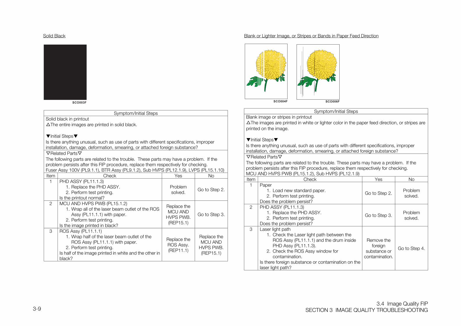
3.4 Image Quality FIPSECTION 3 IMAGE QUALITY TROUBLESHOOTING3-9
Solid Black
Symptom/Initial StepsSolid black in printoutThe entire images are printed in solid black.
Initial StepsIs there anything unusual, such as use of parts with different specifications, improperinstallation, damage, deformation, smearing, or attached foreign substance?Related PartsThe following parts are related to the trouble. These parts may have a problem. If theproblem persists after this FIP procedure, replace them respectively for checking.Fuser Assy 100V (PL9.1.1), BTR Assy (PL9.1.2), Sub HVPS (PL12.1.9), LVPS (PL15.1.10)Item Check Yes No
1 PHD ASSY (PL11.1.3)1. Replace the PHD ASSY.2. Perform test printing.
Is the printout normal?
Problemsolved.
Go to Step 2.
2 MCU AND HVPS PWB (PL15.1.2)1. Wrap all of the laser beam outlet of the ROS
Assy (PL11.1.1) with paper.2. Perform test printing.
Is the image printed in black?
Replace theMCU AND
HVPS PWB.(REP15.1)
Go to Step 3.
3 ROS Assy (PL11.1.1)1. Wrap half of the laser beam outlet of the
ROS Assy (PL11.1.1) with paper.2. Perform test printing.
Is half of the image printed in white and the other inblack?
Replace theROS Assy.(REP11.1)
Replace theMCU AND
HVPS PWB.(REP15.1)
Blank or Lighter Image, or Stripes or Bands in Paper Feed Direction
Symptom/Initial StepsBlank image or stripes in printoutThe images are printed in white or lighter color in the paper feed direction, or stripes areprinted on the image.
Initial StepsIs there anything unusual, such as use of parts with different specifications, improperinstallation, damage, deformation, smearing, or attached foreign substance?Related PartsThe following parts are related to the trouble. These parts may have a problem. If theproblem persists after this FIP procedure, replace them respectively for checking.MCU AND HVPS PWB (PL15.1.2), Sub HVPS (PL12.1.9)Item Check Yes No
1 Paper1. Load new standard paper.2. Perform test printing.
Does the problem persist?
Go to Step 2.Problemsolved.
2 PHD ASSY (PL11.1.3)1. Replace the PHD ASSY.2. Perform test printing.
Does the problem persist?
Go to Step 3.Problemsolved.
3 Laser light path1. Check the Laser light path between the
ROS Assy (PL11.1.1) and the drum inside PHD Assy (PL11.1.3).
2. Check the ROS Assy window for contamination.
Is there foreign substance or contamination on thelaser light path?
Remove theforeign
substance orcontamination.
Go to Step 4.
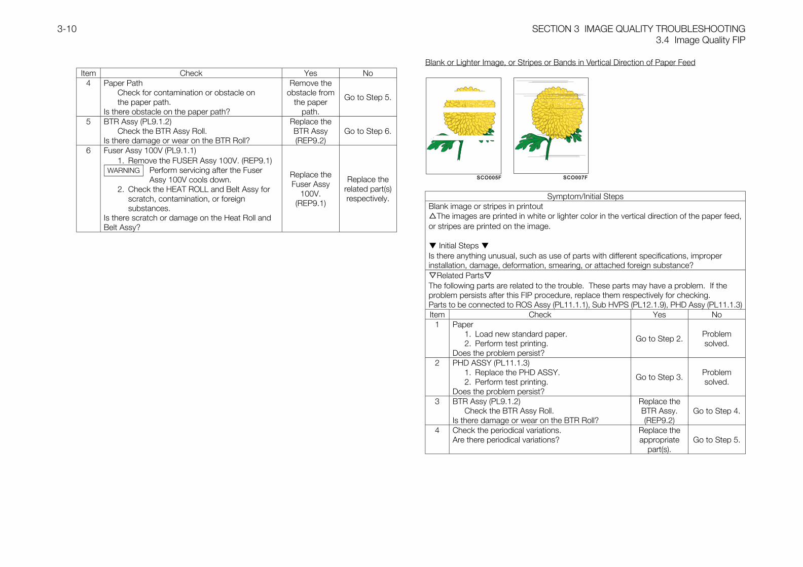
SECTION 3 IMAGE QUALITY TROUBLESHOOTING3.4 Image Quality FIP
3-10
Item Check Yes No4 Paper Path
Check for contamination or obstacle onthe paper path.
Is there obstacle on the paper path?
Remove theobstacle from
the paperpath.
Go to Step 5.
5 BTR Assy (PL9.1.2)Check the BTR Assy Roll.
Is there damage or wear on the BTR Roll?
Replace theBTR Assy(REP9.2)
Go to Step 6.
6 Fuser Assy 100V (PL9.1.1)1. Remove the FUSER Assy 100V. (REP9.1)
Perform servicing after the Fuser Assy 100V cools down.
2. Check the HEAT ROLL and Belt Assy for scratch, contamination, or foreign substances.
Is there scratch or damage on the Heat Roll andBelt Assy?
Replace theFuser Assy
100V.(REP9.1)
Replace therelated part(s)respectively.
Blank or Lighter Image, or Stripes or Bands in Vertical Direction of Paper Feed
Symptom/Initial StepsBlank image or stripes in printoutThe images are printed in white or lighter color in the vertical direction of the paper feed,or stripes are printed on the image.
Initial Steps Is there anything unusual, such as use of parts with different specifications, improperinstallation, damage, deformation, smearing, or attached foreign substance?Related PartsThe following parts are related to the trouble. These parts may have a problem. If theproblem persists after this FIP procedure, replace them respectively for checking.Parts to be connected to ROS Assy (PL11.1.1), Sub HVPS (PL12.1.9), PHD Assy (PL11.1.3)Item Check Yes No
1 Paper1. Load new standard paper.2. Perform test printing.
Does the problem persist?
Go to Step 2.Problemsolved.
2 PHD ASSY (PL11.1.3)1. Replace the PHD ASSY.2. Perform test printing.
Does the problem persist?
Go to Step 3.Problemsolved.
3 BTR Assy (PL9.1.2)Check the BTR Assy Roll.
Is there damage or wear on the BTR Roll?
Replace theBTR Assy.(REP9.2)
Go to Step 4.
4 Check the periodical variations.Are there periodical variations?
Replace theappropriate
part(s).Go to Step 5.
WARNING
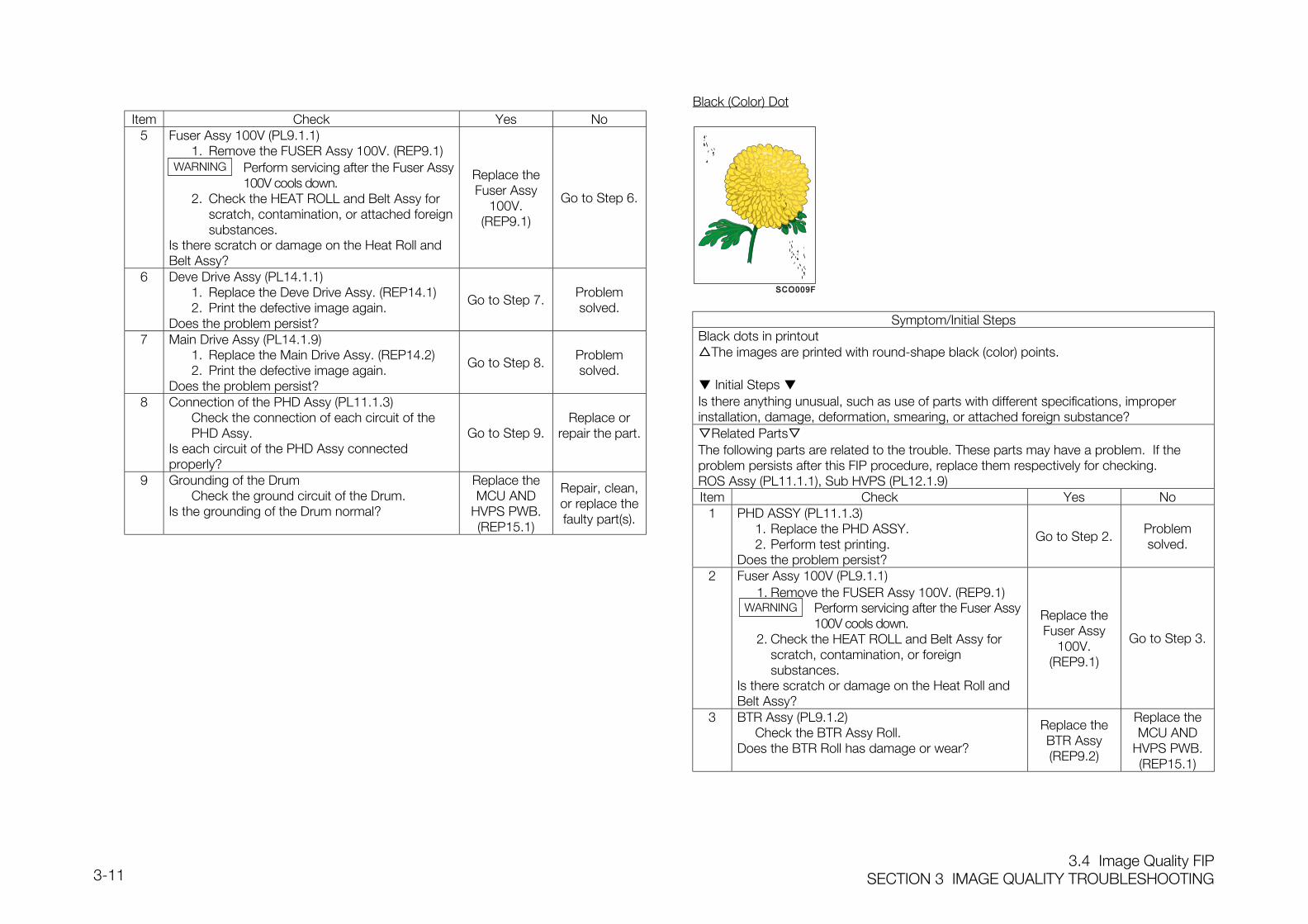
3.4 Image Quality FIPSECTION 3 IMAGE QUALITY TROUBLESHOOTING3-11
Item Check Yes No5 Fuser Assy 100V (PL9.1.1)
1. Remove the FUSER Assy 100V. (REP9.1)Perform servicing after the Fuser Assy100V cools down.
2. Check the HEAT ROLL and Belt Assy for scratch, contamination, or attached foreignsubstances.
Is there scratch or damage on the Heat Roll andBelt Assy?
Replace theFuser Assy
100V.(REP9.1)
Go to Step 6.
6 Deve Drive Assy (PL14.1.1)1. Replace the Deve Drive Assy. (REP14.1)2. Print the defective image again.
Does the problem persist?
Go to Step 7.Problemsolved.
7 Main Drive Assy (PL14.1.9)1. Replace the Main Drive Assy. (REP14.2)2. Print the defective image again.
Does the problem persist?
Go to Step 8.Problemsolved.
8 Connection of the PHD Assy (PL11.1.3)Check the connection of each circuit of the PHD Assy.
Is each circuit of the PHD Assy connectedproperly?
Go to Step 9.Replace or
repair the part.
9 Grounding of the DrumCheck the ground circuit of the Drum.
Is the grounding of the Drum normal?
Replace theMCU AND
HVPS PWB.(REP15.1)
Repair, clean,or replace thefaulty part(s).
Black (Color) Dot
Symptom/Initial StepsBlack dots in printoutThe images are printed with round-shape black (color) points.
Initial Steps Is there anything unusual, such as use of parts with different specifications, improperinstallation, damage, deformation, smearing, or attached foreign substance?Related PartsThe following parts are related to the trouble. These parts may have a problem. If theproblem persists after this FIP procedure, replace them respectively for checking.ROS Assy (PL11.1.1), Sub HVPS (PL12.1.9)Item Check Yes No
1 PHD ASSY (PL11.1.3)1. Replace the PHD ASSY.2. Perform test printing.
Does the problem persist?
Go to Step 2.Problemsolved.
2 Fuser Assy 100V (PL9.1.1)1. Remove the FUSER Assy 100V. (REP9.1)
Perform servicing after the Fuser Assy100V cools down.
2. Check the HEAT ROLL and Belt Assy for scratch, contamination, or foreign substances.
Is there scratch or damage on the Heat Roll andBelt Assy?
Replace theFuser Assy
100V.(REP9.1)
Go to Step 3.
3 BTR Assy (PL9.1.2)Check the BTR Assy Roll.
Does the BTR Roll has damage or wear?
Replace theBTR Assy(REP9.2)
Replace theMCU AND
HVPS PWB.(REP15.1)
WARNING
WARNING
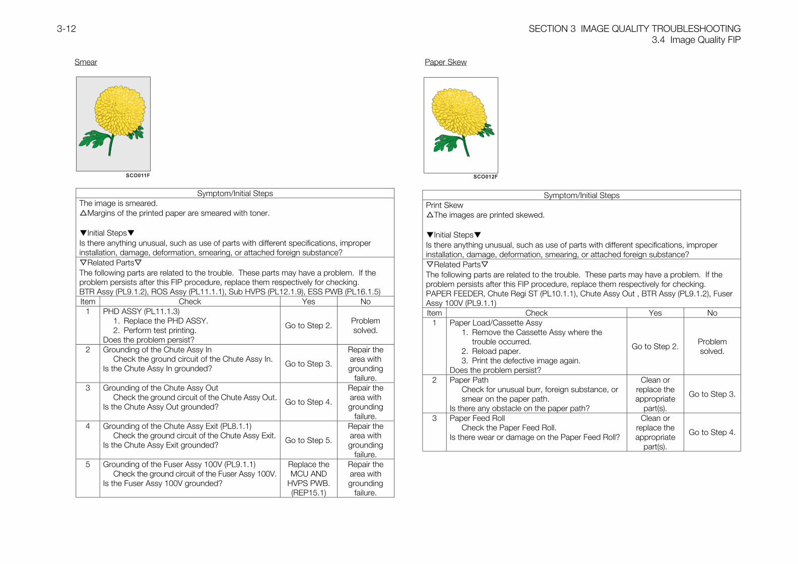
SECTION 3 IMAGE QUALITY TROUBLESHOOTING3.4 Image Quality FIP
3-12
Smear
Symptom/Initial StepsThe image is smeared.Margins of the printed paper are smeared with toner.
Initial StepsIs there anything unusual, such as use of parts with different specifications, improperinstallation, damage, deformation, smearing, or attached foreign substance?Related PartsThe following parts are related to the trouble. These parts may have a problem. If theproblem persists after this FIP procedure, replace them respectively for checking.BTR Assy (PL9.1.2), ROS Assy (PL11.1.1), Sub HVPS (PL12.1.9), ESS PWB (PL16.1.5)Item Check Yes No
1 PHD ASSY (PL11.1.3)1. Replace the PHD ASSY.2. Perform test printing.
Does the problem persist?
Go to Step 2.Problemsolved.
2 Grounding of the Chute Assy InCheck the ground circuit of the Chute Assy In.
Is the Chute Assy In grounded?Go to Step 3.
Repair thearea withgrounding
failure.3 Grounding of the Chute Assy Out
Check the ground circuit of the Chute Assy Out.Is the Chute Assy Out grounded?
Go to Step 4.
Repair thearea withgrounding
failure.4 Grounding of the Chute Assy Exit (PL8.1.1)
Check the ground circuit of the Chute Assy Exit.Is the Chute Assy Exit grounded?
Go to Step 5.
Repair thearea withgrounding
failure.5 Grounding of the Fuser Assy 100V (PL9.1.1)
Check the ground circuit of the Fuser Assy 100V.Is the Fuser Assy 100V grounded?
Replace theMCU AND
HVPS PWB.(REP15.1)
Repair thearea withgrounding
failure.
Paper Skew
Symptom/Initial StepsPrint SkewThe images are printed skewed.
Initial StepsIs there anything unusual, such as use of parts with different specifications, improperinstallation, damage, deformation, smearing, or attached foreign substance?Related PartsThe following parts are related to the trouble. These parts may have a problem. If theproblem persists after this FIP procedure, replace them respectively for checking.PAPER FEEDER, Chute Regi ST (PL10.1.1), Chute Assy Out , BTR Assy (PL9.1.2), FuserAssy 100V (PL9.1.1)Item Check Yes No
1 Paper Load/Cassette Assy1. Remove the Cassette Assy where the
trouble occurred.2. Reload paper.3. Print the defective image again.
Does the problem persist?
Go to Step 2.Problemsolved.
2 Paper PathCheck for unusual burr, foreign substance, orsmear on the paper path.
Is there any obstacle on the paper path?
Clean orreplace theappropriate
part(s).
Go to Step 3.
3 Paper Feed RollCheck the Paper Feed Roll.
Is there wear or damage on the Paper Feed Roll?
Clean orreplace theappropriate
part(s).
Go to Step 4.
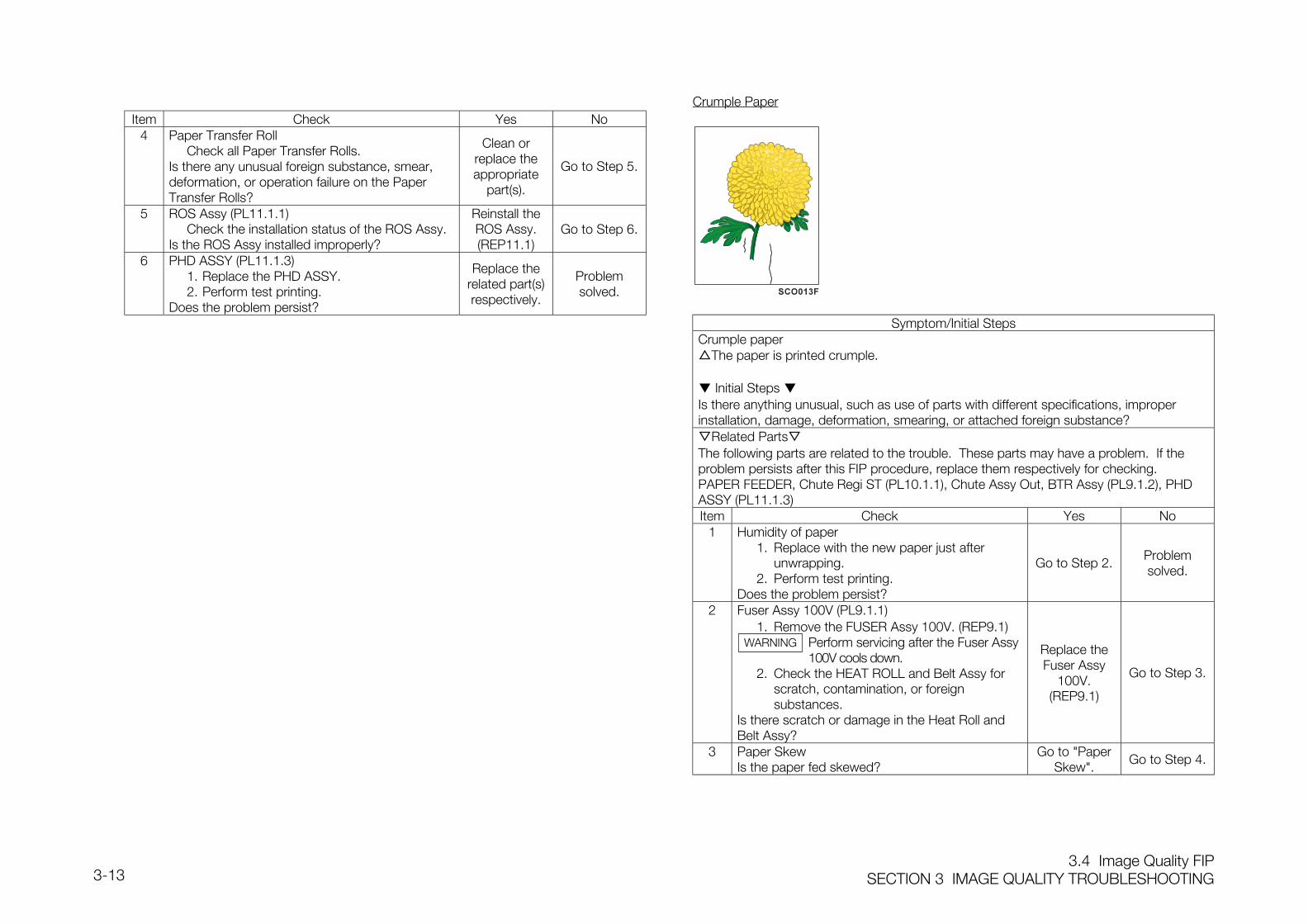
3.4 Image Quality FIPSECTION 3 IMAGE QUALITY TROUBLESHOOTING3-13
Item Check Yes No4 Paper Transfer Roll
Check all Paper Transfer Rolls.Is there any unusual foreign substance, smear,deformation, or operation failure on the PaperTransfer Rolls?
Clean orreplace theappropriate
part(s).
Go to Step 5.
5 ROS Assy (PL11.1.1)Check the installation status of the ROS Assy.
Is the ROS Assy installed improperly?
Reinstall theROS Assy.(REP11.1)
Go to Step 6.
6 PHD ASSY (PL11.1.3)1. Replace the PHD ASSY.2. Perform test printing.
Does the problem persist?
Replace therelated part(s)respectively.
Problemsolved.
Crumple Paper
Symptom/Initial StepsCrumple paperThe paper is printed crumple.
Initial Steps Is there anything unusual, such as use of parts with different specifications, improperinstallation, damage, deformation, smearing, or attached foreign substance?Related PartsThe following parts are related to the trouble. These parts may have a problem. If theproblem persists after this FIP procedure, replace them respectively for checking.PAPER FEEDER, Chute Regi ST (PL10.1.1), Chute Assy Out, BTR Assy (PL9.1.2), PHDASSY (PL11.1.3)Item Check Yes No
1 Humidity of paper1. Replace with the new paper just after
unwrapping.2. Perform test printing.
Does the problem persist?
Go to Step 2.Problemsolved.
2 Fuser Assy 100V (PL9.1.1)1. Remove the FUSER Assy 100V. (REP9.1)
Perform servicing after the Fuser Assy 100V cools down.
2. Check the HEAT ROLL and Belt Assy for scratch, contamination, or foreign substances.
Is there scratch or damage in the Heat Roll andBelt Assy?
Replace theFuser Assy
100V.(REP9.1)
Go to Step 3.
3 Paper SkewIs the paper fed skewed?
Go to "PaperSkew".
Go to Step 4.
WARNING
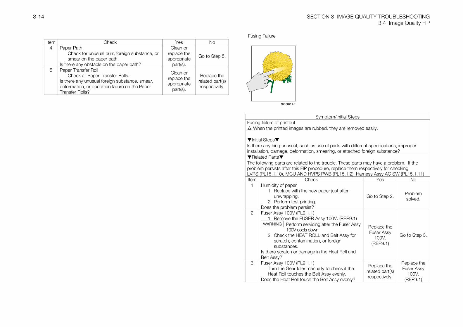
SECTION 3 IMAGE QUALITY TROUBLESHOOTING3.4 Image Quality FIP
3-14
Item Check Yes No4 Paper Path
Check for unusual burr, foreign substance, or smear on the paper path.
Is there any obstacle on the paper path?
Clean orreplace theappropriate
part(s).
Go to Step 5.
5 Paper Transfer RollCheck all Paper Transfer Rolls.
Is there any unusual foreign substance, smear,deformation, or operation failure on the PaperTransfer Rolls?
Clean orreplace theappropriate
part(s).
Replace therelated part(s)respectively.
Fusing Failure
Symptom/Initial StepsFusing failure of printout When the printed images are rubbed, they are removed easily.
Initial StepsIs there anything unusual, such as use of parts with different specifications, improperinstallation, damage, deformation, smearing, or attached foreign substance?Related PartsThe following parts are related to the trouble. These parts may have a problem. If theproblem persists after this FIP procedure, replace them respectively for checking.LVPS (PL15.1.10), MCU AND HVPS PWB (PL15.1.2), Harness Assy AC SW (PL15.1.11)Item Check Yes No
1 Humidity of paper1. Replace with the new paper just after
unwrapping.2. Perform test printing.
Does the problem persist?
Go to Step 2.Problemsolved.
2 Fuser Assy 100V (PL9.1.1)1. Remove the FUSER Assy 100V. (REP9.1)
Perform servicing after the Fuser Assy100V cools down.
2. Check the HEAT ROLL and Belt Assy forscratch, contamination, or foreignsubstances.
Is there scratch or damage in the Heat Roll andBelt Assy?
Replace theFuser Assy
100V.(REP9.1)
Go to Step 3.
3 Fuser Assy 100V (PL9.1.1)Turn the Gear Idler manually to check if the Heat Roll touches the Belt Assy evenly.
Does the Heat Roll touch the Belt Assy evenly?
Replace therelated part(s)respectively.
Replace theFuser Assy
100V.(REP9.1)
WARNING

SECTION 4 DISASSEMBLY AND ASSEMBLY PROCEDURES,ADJUSTMENT

ContentsSECTION 4 DISASSEMBLY AND ASSEMBLY PROCEDURES, ADJUSTMENT4-1
Contents
4.1 Preface ...................................................................................................................... 4
4.1.1 Before Carrying Out the Repair/Adjustment Procedures....................................... 4
4.1.2 How to Use the Repair/Adjustment Procedures Section....................................... 4
4.2 Disassembly and Assembly Procedures ..................................................................... 5
1. Cover ....................................................................................................................... 5
REP1.1 CONTROL PANEL HANABI (PL1.1.1) ........................................................... 5
REP1.2 COVER ASSY FRONT HEAD (PL1.1.2)......................................................... 6
REP1.3 FUSER FAN (PL1.1.9)................................................................................... 7
REP1.4 COVER TOP MAIN (PL1.1.13) ...................................................................... 7
REP1.5 COVER ASSY TOP PHD (PL1.1.15).............................................................. 8
REP1.6 COVER REAR (PL1.1.28) ............................................................................. 8
REP1.7 LINK L (PL1.2.5) ........................................................................................... 9
REP1.8 LINK R (PL1.2.5) .......................................................................................... 9
REP1.9 COVER SIDE R (PL1.2.2)............................................................................ 10
REP1.10 COVER ASSY FRONT (PL1.2.10) ............................................................. 10
REP1.11 COVER MSI (PL1.2.21)............................................................................. 11
REP1.12 TRAY ASSY MSI (PL1.2.12) ...................................................................... 11
REP1.13 COVER ASSY FRONT IN (PL1.2.10) ......................................................... 12
REP1.14 COVER SIDE L (PL1.2.1) .......................................................................... 12
2. CHASSIS & FEEDER/CASSETTE............................................................................ 13
REP2.1 FDR/CST ASSY FX (PL2.1.2)...................................................................... 13
3. PAPER CASSETTE................................................................................................. 14
REP3.1 ROLL ASSY (PL3.1.6)................................................................................. 14
REP3.2 HOLDER RETARD (PL3.1.9) ....................................................................... 14
REP3.3 CASSETTE ASSY FRONT (REFERENCE ONLY).......................................... 15
4. PAPER FEEDER ..................................................................................................... 16
REP4.1 CHUTE ASSY TURN (PL4.1.6) ................................................................... 16
REP4.2 COVER CASSETTE (PL4.1.3) ..................................................................... 16
REP4.3 HSG FDR L (PL4.2.1).................................................................................. 17
REP4.4 HSG FDR R (PL4.2.2) ................................................................................. 18
REP4.5 HUM TEMP SENSOR (PL4.2.4) .................................................................. 19
REP4.6 HARNESS ASSY OPFREC (PL4.2.9)........................................................... 20
REP4.7 TRAY1 SIZE SWITCH ASSY (PL4.2.8)......................................................... 21
REP4.8 LEVER LOW PAPER (PL4.2.10) .................................................................. 22
REP4.9 INDICATOR (PL4.2.11)................................................................................ 23
REP4.10 GUIDE INDICATOR (PL4.2.13) .................................................................. 24
REP4.11 PICKUP ASSY (PL4.3.1) ........................................................................... 25
REP4.12 ROLL ASSY FEED (PL4.3.3) ..................................................................... 26
REP4.13 TRAY1 NO PAPER SENSOR (PL4.3.4) ...................................................... 27
REP4.14 TRAY1 LOW PAPER SENSOR (PL4.3.20) ................................................. 28
REP4.15 ACTUATOR NO PAPER (PL4.3.5) ............................................................. 29
REP4.16 LINK ACTUATOR (PL4.3.6) ....................................................................... 30
REP4.17 TRAY1 FEED SOLENOID (PL4.3.17) ......................................................... 31
REP4.18 TRAY1 TURN CLUTCH ASSY (PL4.3.18) .................................................. 32
REP4.19 ROLL ASSY TURN (PL4.3.21)................................................................... 33
REP4.20 ROLL ASSY (PL4.3.25) ............................................................................. 34
5. HOUSING ASSY RETARD....................................................................................... 35
REP5.1 HOUSING ASSY RETARD (PL5.1.1)............................................................ 35
REP5.2 ROLL TURN (PL5.1.2) ................................................................................ 36
REP5.3 ROLL ASSY RETARD (PL5.1.5)................................................................... 37
REP5.4 MSI TURN CLUTCH (PL5.1.9) .................................................................... 38
REP5.5 STUD RETARD (PL5.1.10) .......................................................................... 38
6. CHUTE ASSY IN..................................................................................................... 39
REP6.1 CHUTE ASSY IN (PL6)................................................................................ 39
REP6.2 ADC SENSOR ASSY (PL6.1.11) ................................................................. 40
REP6.3 WASTE TONER SENSOR (PL6.1.18) .......................................................... 40
REP6.4 FUSER DRIVE ASSY (PL6.2.1).................................................................... 41
REP6.5 LATCH R (PL6.2.12) ................................................................................... 41
REP6.6 LATCH L (PL6.2.22).................................................................................... 42
SECTION 4 DISASSEMBLY AND ASSEMBLY PROCEDURES, ADJUSTMENTContents
4-2
7. CHUTE ASSY OUT................................................................................................. 43
REP7.1 CHUTE ASSY OUT (PL7.1)......................................................................... 43
REP7.2 FULL STACK SENSOR (PL7.1.3) ................................................................ 44
REP7.3 ACTUATOR FULL (PL7.1.4) ........................................................................ 44
REP7.4 DUP JAM SENSOR (PL7.1.13) ................................................................... 45
REP7.5 MSI NO PAPER SENSOR (PL7.2.23) .......................................................... 45
REP7.6 ELIMINATOR ASSY (REFERENCE ONLY) ................................................... 46
REP7.7 ROLL DUP (PL7.1.12) ................................................................................ 46
REP7.8 ACTUATOR DUP (PL7.1.14) ....................................................................... 47
REP7.9 LATCH OUT (PL7.2.2) ................................................................................ 47
REP7.10 ROLL ASSY FEED (PL7.2.11) ................................................................... 48
REP7.11 ACTUATOR MSI (PL7.2.25) ...................................................................... 48
REP7.12 MSI FEED SOLENOID (PL7.2.28) ............................................................. 49
REP7.13 SHAFT ASSY ROLL FEED (REFERENCE ONLY) ....................................... 49
REP7.14 PLATE AS BTM (PL7.2) ............................................................................ 50
8. CHUTE ASSY EXIT................................................................................................. 51
REP8.1 CHUTE ASSY EXIT (PL8.1)......................................................................... 51
REP8.2 ROLL EXIT (PL8.1.4)................................................................................... 51
REP8.3 ROLL MID (PL8.1.5) ................................................................................... 52
REP8.4 DUP MOTOR ASSY (PL8.1.8)..................................................................... 52
9. BTR ASSY & FUSER .............................................................................................. 53
REP9.1 FUSER ASSY 100V (PL9.1.1) ..................................................................... 53
REP9.2 BTR ASSY (PL9.1.2)................................................................................... 53
REP9.3 STRAP (PL9.1.3) ........................................................................................ 54
10. REGISTRATION.................................................................................................... 55
REP10.1 CHUTE REGI ST (PL10.1.1)...................................................................... 55
REP10.2 REGI SENSOR (PL10.1.20) ...................................................................... 56
REP10.3 ACTUATOR REGI (PL10.1.21) .................................................................. 56
REP10.4 OHP SENSOR (PL10.1.16)....................................................................... 57
11. XEROGRAPHICS ................................................................................................. 58
REP11.1 ROS ASSY (PL11.1.1) .............................................................................. 58
REP11.2 HSG ASSY BIAS (PL11.1.4)...................................................................... 58
12. TCRU ASSY ......................................................................................................... 59
REP12.1 HOLDER TCRU ASSY UNIT (REFERENCE ONLY)..................................... 59
REP12.2 HOLDER TONER ASSY (Y) (PL12.2.1) ...................................................... 60
REP12.3 HOLDER TONER ASSY (M) (PL12.2.2) ..................................................... 61
REP12.4 HOLDER TONER ASSY (C) (PL12.2.3) ...................................................... 61
REP12.5 HOLDER TONER ASSY (K) (PL12.2.4) ...................................................... 62
REP12.6 TCRU SWITCH ASSY (PL12.2.30) ............................................................ 62
REP12.7 LOW TONER SENSOR (PL12.2.28) .......................................................... 63
REP12.8 EEPROM PWB (PL12.1.8) ........................................................................ 63
REP12.9 SUB HVPS (PL12.1.9) .............................................................................. 64
13. FRAME................................................................................................................. 65
REP13.1 LEVER DRUM: L (PL13.1.4) ...................................................................... 65
REP13.2 LEVER DRUM: R (PL13.1.4) ..................................................................... 66
REP13.3 ACTUATOR I/R (PL13.1.8) ........................................................................ 67
REP13.4 PWBA ASSY EARTH (PL13.1.17) ............................................................. 67
14. DRIVE................................................................................................................... 68
REP14.1 DEVE DRIVE ASSY (PL14.1.1) .................................................................. 68
REP14.2 MAIN DRIVE ASSY (PL14.1.9) .................................................................. 68
15. ELECTRICAL ........................................................................................................ 69
REP15.1 MCU AND HVPS PWB (PL15.1.2)............................................................. 69
REP15.2 FAN REAR (PL15.1.3) ............................................................................... 69
REP15.3 LVPS (PL15.1.10)...................................................................................... 70
REP15.4 HARNESS ASSY AC SW (PL15.1.11) ....................................................... 70
REP15.5 DRIVE PWB (PL15.1.15) ........................................................................... 71
REP15.6 BOX ASSY MCU/ESS (REFERENCE ONLY) .............................................. 71
REP15.7 HOUSING ASSY CONTACT (PL15.1.8)..................................................... 72
16. ESS ...................................................................................................................... 73
REP16.1 ESS PWB (PL16.1.5) ................................................................................ 73
17. 2TRAY MODULE................................................................................................... 74
REP17.1 COVER FRONT (PL17.1.5) ....................................................................... 74
ContentsSECTION 4 DISASSEMBLY AND ASSEMBLY PROCEDURES, ADJUSTMENT4-3
REP17.2 COVER R (PL17.1.4) ................................................................................ 74
REP17.3 COVER L (PL17.1.1)................................................................................. 75
REP17.4 CHUTE ASSY TURN (PL4.2.8).................................................................. 75
REP17.5 HARNESS ASSY FDR 2T (PL17.4.3) ........................................................ 76
REP17.6 HARNESS ASSY FDR 3T (PL17.4.4) ........................................................ 76
REP17.7 FEEDER DRIVE ASSY (PL17.4.5) ............................................................. 77
REP17.8 INDICATOR ASSY (PL17.4.10) ................................................................. 77
REP17.9 HARNESS ASSY OPF PLG (PL17.4.2)...................................................... 78
REP17.10 FEEDER PWB (PL17.4.1) ....................................................................... 78
REP17.11 GUIDE ASSY CASSETTE R (PL17.2.6) ................................................... 79
REP17.12 GUIDE ASSY CASSETTE L (PL17.2.3).................................................... 81
REP17.13 LINK ACTUATOR (PL17.3.6)................................................................... 81
REP17.14 PICK UP ASSY TR2 (PL17.3.1)............................................................... 82
REP17.15 PICK UP ASSY TR3 (PL17.3.1)............................................................... 82
REP17.16 GEAR IDLER (PL17.4.6) ......................................................................... 83
REP17.17 LOW PAPER SENSOR (PL17.4.7/PL17.4.8) ........................................... 83
REP17.18 CASTER ASSYS (PL17.1.6).................................................................... 84
REP17.19 CASTER ASSY (PL17.1.7) ...................................................................... 84
REP17.20 SIZE SWITCH ASSY (PL17.2.7) .............................................................. 85
REP17.21 STOPPER CST (PL17.2.4)...................................................................... 85
REP17.22 FEED SOLENOID (PL17.3.17) ................................................................ 86
REP17.23 SPRING FEED H (PL17.3.10) ................................................................. 86
REP17.24 SPRING FEED 1 (PL17.3.9) .................................................................... 87
REP17.25 GEAR FEED H2 (PL17.3.11) ................................................................... 87
REP17.26 GEAR FEED 1 (PL17.3.8) ....................................................................... 88
REP17.27 GEAR FEED H1 (PL17.3.12) ................................................................... 88
REP17.28 GEAR FEED 2 (PL17.3.13) ..................................................................... 89
REP17.29 STOPPER CLUTCH (PL17.3.16)............................................................. 89
REP17.30 TURN CLUTCH ASSY (PL17.3.18) ......................................................... 90
REP17.31 GEAR IDLER (PL17.3.15) ....................................................................... 91
REP17.32 GEAR IDLER FEED (PL17.3.14).............................................................. 92
REP17.33 GEAR IDLER IN (PL17.3.19) ................................................................... 93
REP17.34 ROLL ASSY FEED (PL17.3.3) ................................................................. 94
REP17.35 ACTUATOR NO PAPER (PL17.3.5) ......................................................... 94
REP17.36 NO PAPER SENSOR (PL17.3.4) ............................................................. 95
REP17.37 ROLL ASSY (PL17.3.24) ......................................................................... 96
REP17.38 BEARING (PL17.3.7)............................................................................... 97
REP17.39 BEARING SLEEVE (PL17.3.21) ............................................................... 98
REP17.40 ROLL ASSY TURN (PL17.3.20)............................................................... 99
REP17.41 SHAFT FEED 1 (PL17.3.2) .................................................................... 100
REP17.42 SHAFT FEED 2 (PL17.3.22) .................................................................. 101
4.3 Adjustment............................................................................................................. 102
ADJ1 Firmware Version Upgrade .............................................................................. 102
ADJ1.1 ESS PWB (Parallel connection: IEEE1284)................................................. 102
ADJ1.2 ESS PWB (FTP) ........................................................................................ 103
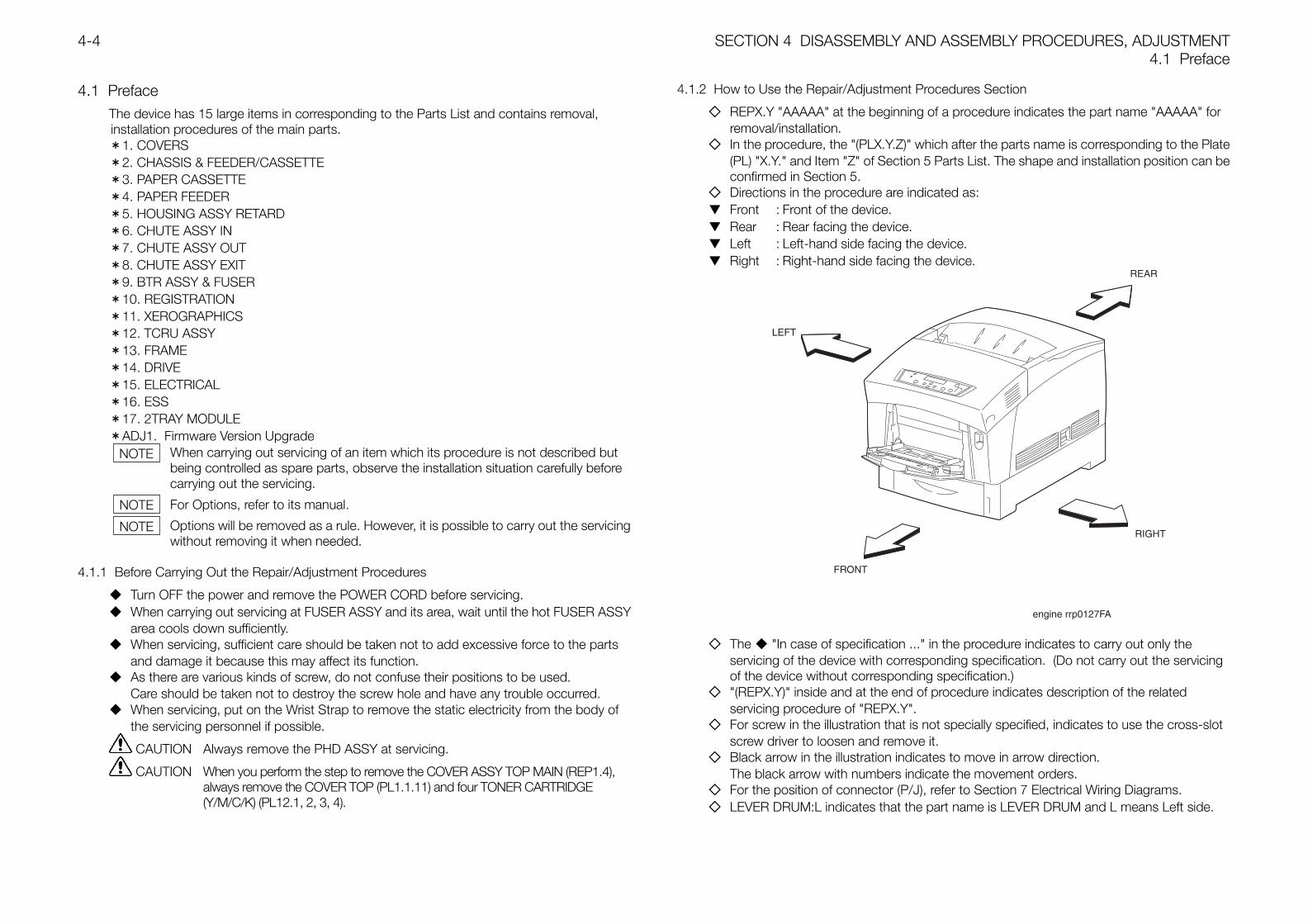
SECTION 4 DISASSEMBLY AND ASSEMBLY PROCEDURES, ADJUSTMENT4.1 Preface
4-4
4.1 PrefaceThe device has 15 large items in corresponding to the Parts List and contains removal,installation procedures of the main parts.*1. COVERS*2. CHASSIS & FEEDER/CASSETTE*3. PAPER CASSETTE*4. PAPER FEEDER*5. HOUSING ASSY RETARD*6. CHUTE ASSY IN*7. CHUTE ASSY OUT*8. CHUTE ASSY EXIT*9. BTR ASSY & FUSER*10. REGISTRATION*11. XEROGRAPHICS*12. TCRU ASSY*13. FRAME*14. DRIVE*15. ELECTRICAL*16. ESS*17. 2TRAY MODULE*ADJ1. Firmware Version Upgrade
When carrying out servicing of an item which its procedure is not described butbeing controlled as spare parts, observe the installation situation carefully beforecarrying out the servicing.
For Options, refer to its manual.
Options will be removed as a rule. However, it is possible to carry out the servicingwithout removing it when needed.
4.1.1 Before Carrying Out the Repair/Adjustment Procedures
Turn OFF the power and remove the POWER CORD before servicing. When carrying out servicing at FUSER ASSY and its area, wait until the hot FUSER ASSY
area cools down sufficiently. When servicing, sufficient care should be taken not to add excessive force to the parts
and damage it because this may affect its function. As there are various kinds of screw, do not confuse their positions to be used.
Care should be taken not to destroy the screw hole and have any trouble occurred. When servicing, put on the Wrist Strap to remove the static electricity from the body of
the servicing personnel if possible.
CAUTION Always remove the PHD ASSY at servicing.
CAUTION When you perform the step to remove the COVER ASSY TOP MAIN (REP1.4),always remove the COVER TOP (PL1.1.11) and four TONER CARTRIDGE(Y/M/C/K) (PL12.1, 2, 3, 4).
4.1.2 How to Use the Repair/Adjustment Procedures Section
REPX.Y "AAAAA" at the beginning of a procedure indicates the part name "AAAAA" forremoval/installation.
In the procedure, the "(PLX.Y.Z)" which after the parts name is corresponding to the Plate(PL) "X.Y." and Item "Z" of Section 5 Parts List. The shape and installation position can beconfirmed in Section 5.
Directions in the procedure are indicated as: Front : Front of the device. Rear : Rear facing the device. Left : Left-hand side facing the device. Right : Right-hand side facing the device.
The "In case of specification ..." in the procedure indicates to carry out only theservicing of the device with corresponding specification. (Do not carry out the servicingof the device without corresponding specification.)
"(REPX.Y)" inside and at the end of procedure indicates description of the relatedservicing procedure of "REPX.Y".
For screw in the illustration that is not specially specified, indicates to use the cross-slotscrew driver to loosen and remove it.
Black arrow in the illustration indicates to move in arrow direction.The black arrow with numbers indicate the movement orders.
For the position of connector (P/J), refer to Section 7 Electrical Wiring Diagrams. LEVER DRUM:L indicates that the part name is LEVER DRUM and L means Left side.
NOTE
NOTE
NOTE
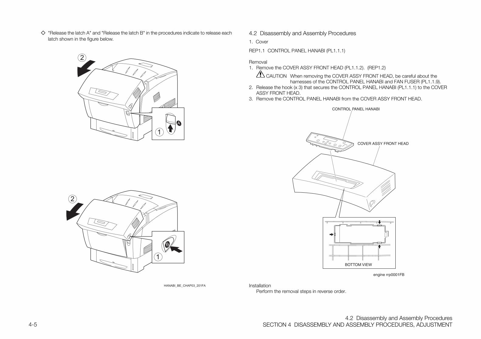
4.2 Disassembly and Assembly ProceduresSECTION 4 DISASSEMBLY AND ASSEMBLY PROCEDURES, ADJUSTMENT4-5
"Release the latch A" and "Release the latch B" in the procedures indicate to release eachlatch shown in the figure below.
HANABI_BE_CHAP03_201FA
1
1
2
2
4.2 Disassembly and Assembly Procedures1. Cover
REP1.1 CONTROL PANEL HANABI (PL1.1.1)
Removal1. Remove the COVER ASSY FRONT HEAD (PL1.1.2). (REP1.2)
CAUTION When removing the COVER ASSY FRONT HEAD, be careful about theharnesses of the CONTROL PANEL HANABI and FAN FUSER (PL1.1.9).
2. Release the hook (x 3) that secures the CONTROL PANEL HANABI (PL1.1.1) to the COVERASSY FRONT HEAD.
3. Remove the CONTROL PANEL HANABI from the COVER ASSY FRONT HEAD.
InstallationPerform the removal steps in reverse order.
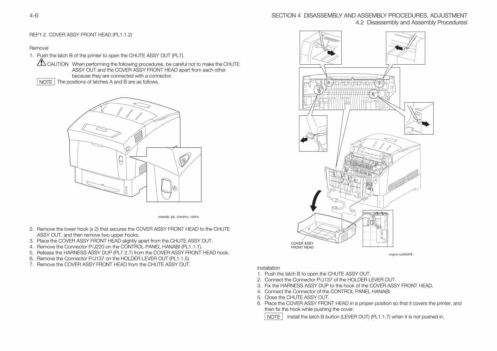
SECTION 4 DISASSEMBLY AND ASSEMBLY PROCEDURES, ADJUSTMENT4.2 Disassembly and Assembly Proceduresl
4-6
REP1.2 COVER ASSY FRONT HEAD (PL1.1.2)
Removal
1. Push the latch B of the printer to open the CHUTE ASSY OUT (PL7).
CAUTION When performing the following procedures, be careful not to make the CHUTEASSY OUT and the COVER ASSY FRONT HEAD apart from each otherbecause they are connected with a connector.
The positions of latches A and B are as follows.
HANABI_BE_CHAP03_100FA
2. Remove the lower hook (x 2) that secures the COVER ASSY FRONT HEAD to the CHUTEASSY OUT, and then remove two upper hooks.
3. Place the COVER ASSY FRONT HEAD slightly apart from the CHUTE ASSY OUT.4. Remove the Connector P/J220 on the CONTROL PANEL HANABI (PL1.1.1).5. Release the HARNESS ASSY DUP (PL7.2.7) from the COVER ASSY FRONT HEAD hook.6. Remove the Connector P/J137 on the HOLDER LEVER OUT (PL1.1.5).7. Remove the COVER ASSY FRONT HEAD from the CHUTE ASSY OUT.
engine rrp0002FB
Installation1. Push the latch B to open the CHUTE ASSY OUT.2. Connect the Connector P/J137 of the HOLDER LEVER OUT.3. Fix the HARNESS ASSY DUP to the hook of the COVER ASSY FRONT HEAD.4. Connect the Connector of the CONTROL PANEL HANABI.5. Close the CHUTE ASSY OUT.6. Place the COVER ASSY FRONT HEAD in a proper position so that it covers the printer, and
then fix the hook while pushing the cover.
Install the latch B button (LEVER OUT) (PL1.1.7) when it is not pushed in.
NOTE
NOTE
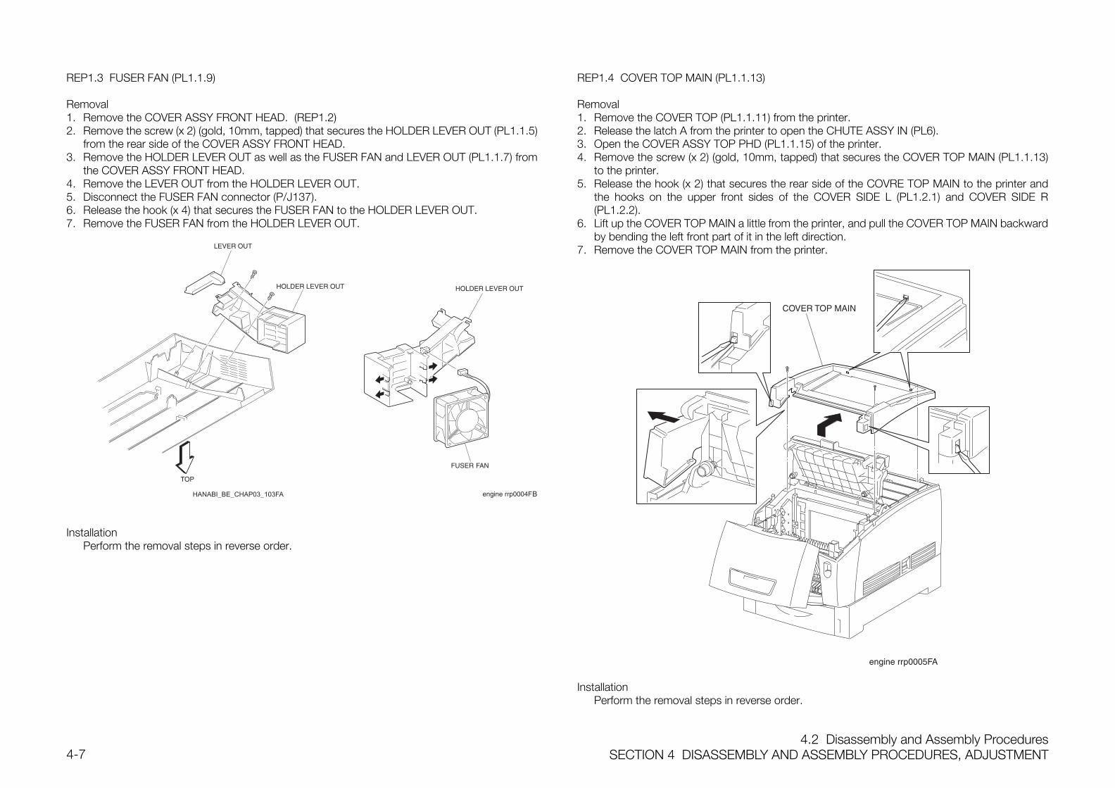
4.2 Disassembly and Assembly ProceduresSECTION 4 DISASSEMBLY AND ASSEMBLY PROCEDURES, ADJUSTMENT4-7
REP1.3 FUSER FAN (PL1.1.9)
Removal1. Remove the COVER ASSY FRONT HEAD. (REP1.2)2. Remove the screw (x 2) (gold, 10mm, tapped) that secures the HOLDER LEVER OUT (PL1.1.5)
from the rear side of the COVER ASSY FRONT HEAD.3. Remove the HOLDER LEVER OUT as well as the FUSER FAN and LEVER OUT (PL1.1.7) from
the COVER ASSY FRONT HEAD.4. Remove the LEVER OUT from the HOLDER LEVER OUT.5. Disconnect the FUSER FAN connector (P/J137).6. Release the hook (x 4) that secures the FUSER FAN to the HOLDER LEVER OUT.7. Remove the FUSER FAN from the HOLDER LEVER OUT.
HANABI_BE_CHAP03_103FA B
InstallationPerform the removal steps in reverse order.
REP1.4 COVER TOP MAIN (PL1.1.13)
Removal1. Remove the COVER TOP (PL1.1.11) from the printer.2. Release the latch A from the printer to open the CHUTE ASSY IN (PL6).3. Open the COVER ASSY TOP PHD (PL1.1.15) of the printer.4. Remove the screw (x 2) (gold, 10mm, tapped) that secures the COVER TOP MAIN (PL1.1.13)
to the printer.5. Release the hook (x 2) that secures the rear side of the COVRE TOP MAIN to the printer and
the hooks on the upper front sides of the COVER SIDE L (PL1.2.1) and COVER SIDE R(PL1.2.2).
6. Lift up the COVER TOP MAIN a little from the printer, and pull the COVER TOP MAIN backwardby bending the left front part of it in the left direction.
7. Remove the COVER TOP MAIN from the printer.
InstallationPerform the removal steps in reverse order.
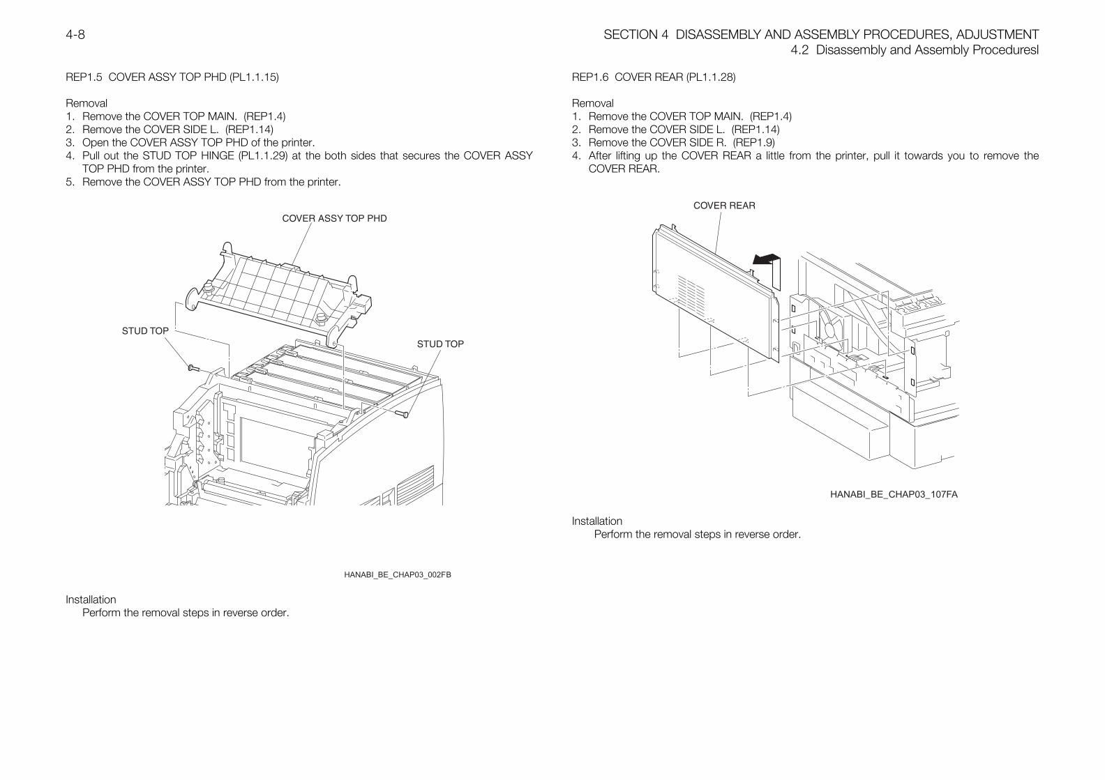
SECTION 4 DISASSEMBLY AND ASSEMBLY PROCEDURES, ADJUSTMENT4.2 Disassembly and Assembly Proceduresl
4-8
REP1.5 COVER ASSY TOP PHD (PL1.1.15)
Removal1. Remove the COVER TOP MAIN. (REP1.4)2. Remove the COVER SIDE L. (REP1.14)3. Open the COVER ASSY TOP PHD of the printer.4. Pull out the STUD TOP HINGE (PL1.1.29) at the both sides that secures the COVER ASSY
TOP PHD from the printer.5. Remove the COVER ASSY TOP PHD from the printer.
InstallationPerform the removal steps in reverse order.
REP1.6 COVER REAR (PL1.1.28)
Removal1. Remove the COVER TOP MAIN. (REP1.4)2. Remove the COVER SIDE L. (REP1.14)3. Remove the COVER SIDE R. (REP1.9)4. After lifting up the COVER REAR a little from the printer, pull it towards you to remove the
COVER REAR.
HANABI_BE_CHAP03_107FA
InstallationPerform the removal steps in reverse order.
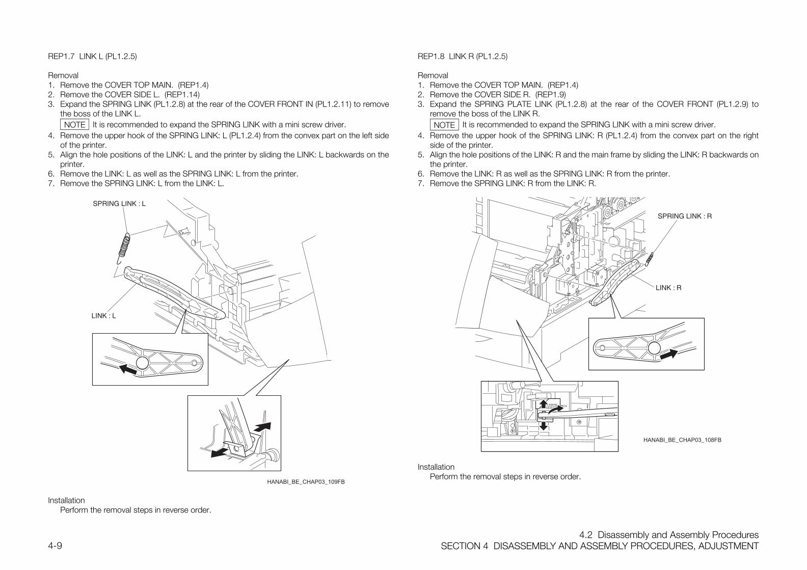
4.2 Disassembly and Assembly ProceduresSECTION 4 DISASSEMBLY AND ASSEMBLY PROCEDURES, ADJUSTMENT4-9
REP1.7 LINK L (PL1.2.5)
Removal1. Remove the COVER TOP MAIN. (REP1.4)2. Remove the COVER SIDE L. (REP1.14)3. Expand the SPRING LINK (PL1.2.8) at the rear of the COVER FRONT IN (PL1.2.11) to remove
the boss of the LINK L.It is recommended to expand the SPRING LINK with a mini screw driver.
4. Remove the upper hook of the SPRING LINK: L (PL1.2.4) from the convex part on the left sideof the printer.
5. Align the hole positions of the LINK: L and the printer by sliding the LINK: L backwards on theprinter.
6. Remove the LINK: L as well as the SPRING LINK: L from the printer.7. Remove the SPRING LINK: L from the LINK: L.
HANABI_BE_CHAP03_109FB
InstallationPerform the removal steps in reverse order.
REP1.8 LINK R (PL1.2.5)
Removal1. Remove the COVER TOP MAIN. (REP1.4)2. Remove the COVER SIDE R. (REP1.9)3. Expand the SPRING PLATE LINK (PL1.2.8) at the rear of the COVER FRONT (PL1.2.9) to
remove the boss of the LINK R.It is recommended to expand the SPRING LINK with a mini screw driver.
4. Remove the upper hook of the SPRING LINK: R (PL1.2.4) from the convex part on the rightside of the printer.
5. Align the hole positions of the LINK: R and the main frame by sliding the LINK: R backwards onthe printer.
6. Remove the LINK: R as well as the SPRING LINK: R from the printer.7. Remove the SPRING LINK: R from the LINK: R.
HANABI_BE_CHAP03_108FB
InstallationPerform the removal steps in reverse order.
NOTE NOTE
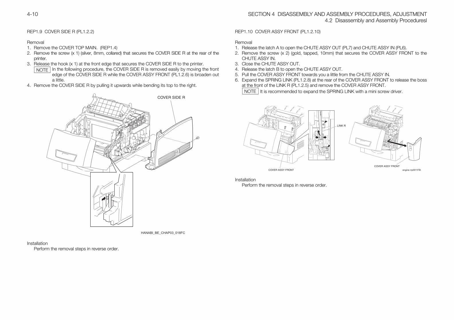
SECTION 4 DISASSEMBLY AND ASSEMBLY PROCEDURES, ADJUSTMENT4.2 Disassembly and Assembly Proceduresl
4-10
REP1.9 COVER SIDE R (PL1.2.2)
Removal1. Remove the COVER TOP MAIN. (REP1.4)2. Remove the screw (x 1) (silver, 8mm, collared) that secures the COVER SIDE R at the rear of the
printer.3. Release the hook (x 1) at the front edge that secures the COVER SIDE R to the printer.
In the following procedure, the COVER SIDE R is removed easily by moving the frontedge of the COVER SIDE R while the COVER ASSY FRONT (PL1.2.6) is broaden outa little.
4. Remove the COVER SIDE R by pulling it upwards while bending its top to the right.
HANABI_BE_CHAP03_018FC
InstallationPerform the removal steps in reverse order.
REP1.10 COVER ASSY FRONT (PL1.2.10)
Removal1. Release the latch A to open the CHUTE ASSY OUT (PL7) and CHUTE ASSY IN (PL6).2. Remove the screw (x 2) (gold, tapped, 10mm) that secures the COVER ASSY FRONT to the
CHUTE ASSY IN.3. Close the CHUTE ASSY OUT.4. Release the latch B to open the CHUTE ASSY OUT.5. Pull the COVER ASSY FRONT towards you a little from the CHUTE ASSY IN.6. Expand the SPRING LINK (PL1.2.8) at the rear of the COVER ASSY FRONT to release the boss
at the front of the LINK R (PL1.2.5) and remove the COVER ASSY FRONT.It is recommended to expand the SPRING LINK with a mini screw driver.
LINK R
engine rrp0011FB
InstallationPerform the removal steps in reverse order.
NOTE
NOTE
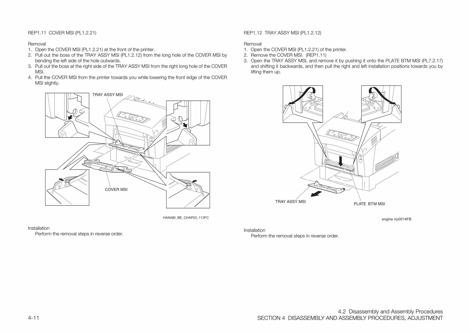
4.2 Disassembly and Assembly ProceduresSECTION 4 DISASSEMBLY AND ASSEMBLY PROCEDURES, ADJUSTMENT4-11
REP1.11 COVER MSI (PL1.2.21)
Removal1. Open the COVER MSI (PL1.2.21) at the front of the printer.2. Pull out the boss of the TRAY ASSY MSI (PL1.2.12) from the long hole of the COVER MSI by
bending the left side of the hole outwards.3. Pull out the boss at the right side of the TRAY ASSY MSI from the right long hole of the COVER
MSI.4. Pull the COVER MSI from the printer towards you while lowering the front edge of the COVER
MSI slightly.
HANABI_BE_CHAP03_113FC
InstallationPerform the removal steps in reverse order.
REP1.12 TRAY ASSY MSI (PL1.2.12)
Removal1. Open the COVER MSI (PL1.2.21) of the printer.2. Remove the COVER MSI. (REP1.11)3. Open the TRAY ASSY MSI, and remove it by pushing it onto the PLATE BTM MSI (PL7.2.17)
and shifting it backwards, and then pull the right and left installation positions towards you bylifting them up.
engine rrp0014FB
InstallationPerform the removal steps in reverse order.
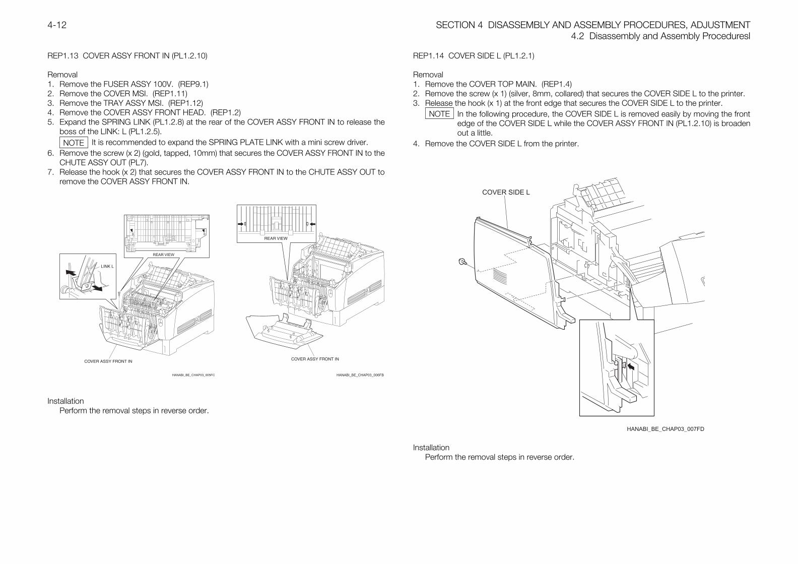
SECTION 4 DISASSEMBLY AND ASSEMBLY PROCEDURES, ADJUSTMENT4.2 Disassembly and Assembly Proceduresl
4-12
REP1.13 COVER ASSY FRONT IN (PL1.2.10)
Removal1. Remove the FUSER ASSY 100V. (REP9.1)2. Remove the COVER MSI. (REP1.11)3. Remove the TRAY ASSY MSI. (REP1.12)4. Remove the COVER ASSY FRONT HEAD. (REP1.2)5. Expand the SPRING LINK (PL1.2.8) at the rear of the COVER ASSY FRONT IN to release the
boss of the LINK: L (PL1.2.5).It is recommended to expand the SPRING PLATE LINK with a mini screw driver.
6. Remove the screw (x 2) (gold, tapped, 10mm) that secures the COVER ASSY FRONT IN to theCHUTE ASSY OUT (PL7).
7. Release the hook (x 2) that secures the COVER ASSY FRONT IN to the CHUTE ASSY OUT toremove the COVER ASSY FRONT IN.
HANABI_BE_CHAP03_005FC
REAR VIEW
InstallationPerform the removal steps in reverse order.
REP1.14 COVER SIDE L (PL1.2.1)
Removal1. Remove the COVER TOP MAIN. (REP1.4)2. Remove the screw (x 1) (silver, 8mm, collared) that secures the COVER SIDE L to the printer.3. Release the hook (x 1) at the front edge that secures the COVER SIDE L to the printer.
In the following procedure, the COVER SIDE L is removed easily by moving the frontedge of the COVER SIDE L while the COVER ASSY FRONT IN (PL1.2.10) is broadenout a little.
4. Remove the COVER SIDE L from the printer.
HANABI_BE_CHAP03_007FD
InstallationPerform the removal steps in reverse order.
NOTE
NOTE
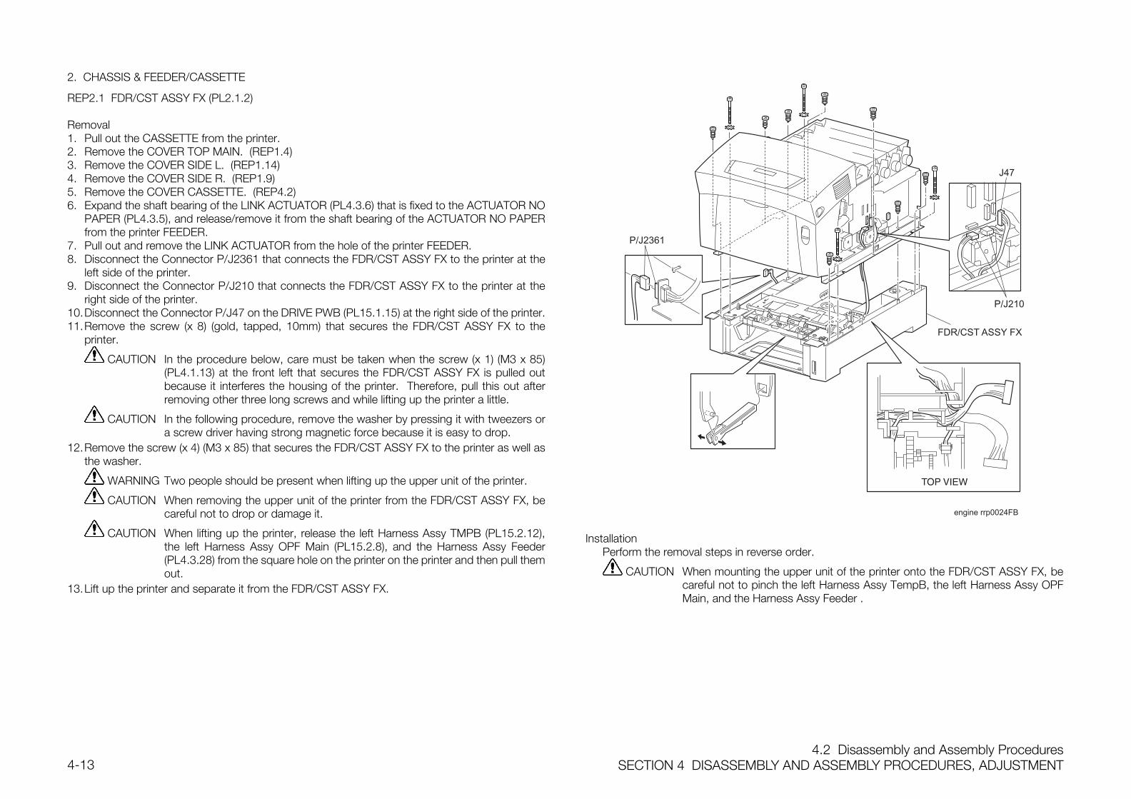
4.2 Disassembly and Assembly ProceduresSECTION 4 DISASSEMBLY AND ASSEMBLY PROCEDURES, ADJUSTMENT4-13
2. CHASSIS & FEEDER/CASSETTE
REP2.1 FDR/CST ASSY FX (PL2.1.2)
Removal1. Pull out the CASSETTE from the printer.2. Remove the COVER TOP MAIN. (REP1.4)3. Remove the COVER SIDE L. (REP1.14)4. Remove the COVER SIDE R. (REP1.9)5. Remove the COVER CASSETTE. (REP4.2)6. Expand the shaft bearing of the LINK ACTUATOR (PL4.3.6) that is fixed to the ACTUATOR NO
PAPER (PL4.3.5), and release/remove it from the shaft bearing of the ACTUATOR NO PAPERfrom the printer FEEDER.
7. Pull out and remove the LINK ACTUATOR from the hole of the printer FEEDER.8. Disconnect the Connector P/J2361 that connects the FDR/CST ASSY FX to the printer at the
left side of the printer.9. Disconnect the Connector P/J210 that connects the FDR/CST ASSY FX to the printer at the
right side of the printer.10.Disconnect the Connector P/J47 on the DRIVE PWB (PL15.1.15) at the right side of the printer.11.Remove the screw (x 8) (gold, tapped, 10mm) that secures the FDR/CST ASSY FX to the
printer.
CAUTION In the procedure below, care must be taken when the screw (x 1) (M3 x 85)(PL4.1.13) at the front left that secures the FDR/CST ASSY FX is pulled outbecause it interferes the housing of the printer. Therefore, pull this out afterremoving other three long screws and while lifting up the printer a little.
CAUTION In the following procedure, remove the washer by pressing it with tweezers ora screw driver having strong magnetic force because it is easy to drop.
12.Remove the screw (x 4) (M3 x 85) that secures the FDR/CST ASSY FX to the printer as well asthe washer.
WARNING Two people should be present when lifting up the upper unit of the printer.
CAUTION When removing the upper unit of the printer from the FDR/CST ASSY FX, becareful not to drop or damage it.
CAUTION When lifting up the printer, release the left Harness Assy TMPB (PL15.2.12),the left Harness Assy OPF Main (PL15.2.8), and the Harness Assy Feeder(PL4.3.28) from the square hole on the printer on the printer and then pull themout.
13.Lift up the printer and separate it from the FDR/CST ASSY FX.
engine rrp0024FB
FDR/CST ASSY FX
J47
P/J210
P/J2361
InstallationPerform the removal steps in reverse order.
CAUTION When mounting the upper unit of the printer onto the FDR/CST ASSY FX, becareful not to pinch the left Harness Assy TempB, the left Harness Assy OPFMain, and the Harness Assy Feeder .
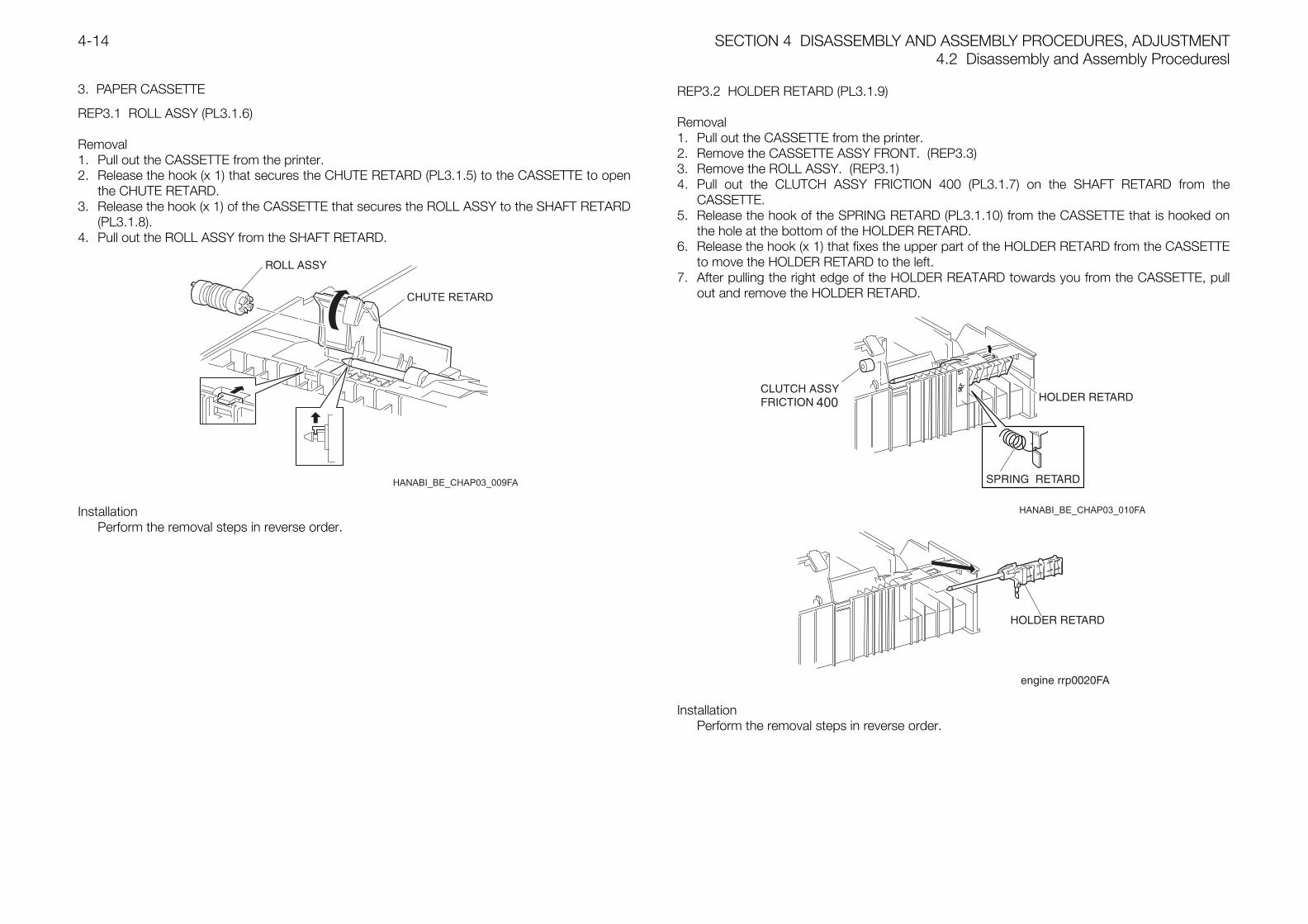
SECTION 4 DISASSEMBLY AND ASSEMBLY PROCEDURES, ADJUSTMENT4.2 Disassembly and Assembly Proceduresl
4-14
3. PAPER CASSETTE
REP3.1 ROLL ASSY (PL3.1.6)
Removal1. Pull out the CASSETTE from the printer.2. Release the hook (x 1) that secures the CHUTE RETARD (PL3.1.5) to the CASSETTE to open
the CHUTE RETARD.3. Release the hook (x 1) of the CASSETTE that secures the ROLL ASSY to the SHAFT RETARD
(PL3.1.8).4. Pull out the ROLL ASSY from the SHAFT RETARD.
InstallationPerform the removal steps in reverse order.
REP3.2 HOLDER RETARD (PL3.1.9)
Removal1. Pull out the CASSETTE from the printer.2. Remove the CASSETTE ASSY FRONT. (REP3.3)3. Remove the ROLL ASSY. (REP3.1)4. Pull out the CLUTCH ASSY FRICTION 400 (PL3.1.7) on the SHAFT RETARD from the
CASSETTE.5. Release the hook of the SPRING RETARD (PL3.1.10) from the CASSETTE that is hooked on
the hole at the bottom of the HOLDER RETARD.6. Release the hook (x 1) that fixes the upper part of the HOLDER RETARD from the CASSETTE
to move the HOLDER RETARD to the left.7. After pulling the right edge of the HOLDER REATARD towards you from the CASSETTE, pull
out and remove the HOLDER RETARD.
InstallationPerform the removal steps in reverse order.
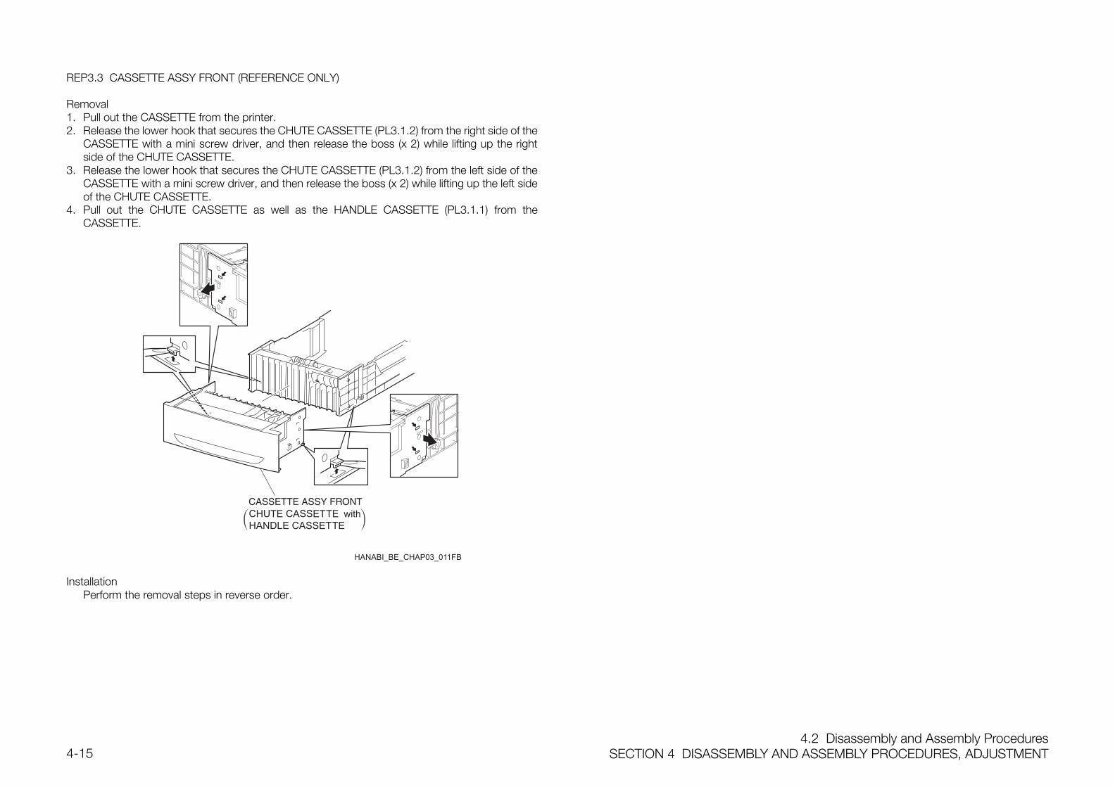
4.2 Disassembly and Assembly ProceduresSECTION 4 DISASSEMBLY AND ASSEMBLY PROCEDURES, ADJUSTMENT4-15
REP3.3 CASSETTE ASSY FRONT (REFERENCE ONLY)
Removal1. Pull out the CASSETTE from the printer.2. Release the lower hook that secures the CHUTE CASSETTE (PL3.1.2) from the right side of the
CASSETTE with a mini screw driver, and then release the boss (x 2) while lifting up the rightside of the CHUTE CASSETTE.
3. Release the lower hook that secures the CHUTE CASSETTE (PL3.1.2) from the left side of theCASSETTE with a mini screw driver, and then release the boss (x 2) while lifting up the left sideof the CHUTE CASSETTE.
4. Pull out the CHUTE CASSETTE as well as the HANDLE CASSETTE (PL3.1.1) from theCASSETTE.
InstallationPerform the removal steps in reverse order.
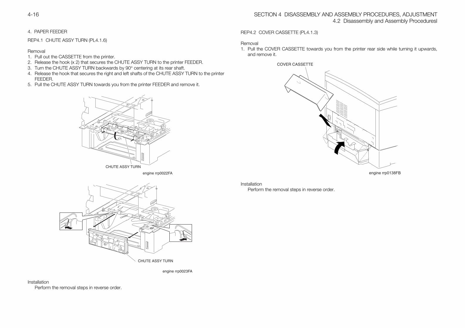
SECTION 4 DISASSEMBLY AND ASSEMBLY PROCEDURES, ADJUSTMENT4.2 Disassembly and Assembly Proceduresl
4-16
4. PAPER FEEDER
REP4.1 CHUTE ASSY TURN (PL4.1.6)
Removal1. Pull out the CASSETTE from the printer.2. Release the hook (x 2) that secures the CHUTE ASSY TURN to the printer FEEDER.3. Turn the CHUTE ASSY TURN backwards by 90° centering at its rear shaft.4. Release the hook that secures the right and left shafts of the CHUTE ASSY TURN to the printer
FEEDER.5. Pull the CHUTE ASSY TURN towards you from the printer FEEDER and remove it.
InstallationPerform the removal steps in reverse order.
REP4.2 COVER CASSETTE (PL4.1.3)
Removal1. Pull the COVER CASSETTE towards you from the printer rear side while turning it upwards,
and remove it.
engine rrp0138FB
InstallationPerform the removal steps in reverse order.
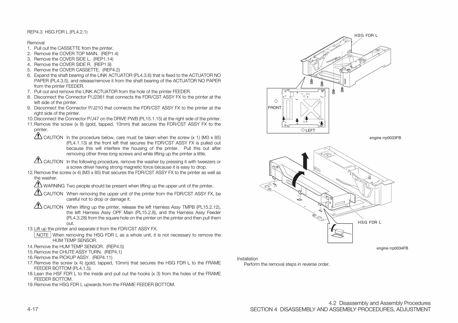
4.2 Disassembly and Assembly ProceduresSECTION 4 DISASSEMBLY AND ASSEMBLY PROCEDURES, ADJUSTMENT4-17
REP4.3 HSG FDR L (PL4.2.1)
Removal1. Pull out the CASSETTE from the printer.2. Remove the COVER TOP MAIN. (REP1.4)3. Remove the COVER SIDE L. (REP1.14)4. Remove the COVER SIDE R. (REP1.9)5. Remove the COVER CASSETTE. (REP4.2)6. Expand the shaft bearing of the LINK ACTUATOR (PL4.3.6) that is fixed to the ACTUATOR NO
PAPER (PL4.3.5), and release/remove it from the shaft bearing of the ACTUATOR NO PAPERfrom the printer FEEDER.
7. Pull out and remove the LINK ACTUATOR from the hole of the printer FEEDER.8. Disconnect the Connector P/J2361 that connects the FDR/CST ASSY FX to the printer at the
left side of the printer.9. Disconnect the Connector P/J210 that connects the FDR/CST ASSY FX to the printer at the
right side of the printer.10.Disconnect the Connector P/J47 on the DRIVE PWB (PL15.1.15) at the right side of the printer.11.Remove the screw (x 8) (gold, tapped, 10mm) that secures the FDR/CST ASSY FX to the
printer.
CAUTION In the procedure below, care must be taken when the screw (x 1) (M3 x 85)(PL4.1.13) at the front left that secures the FDR/CST ASSY FX is pulled outbecause this will interfere the housing of the printer. Pull this out afterremoving other three long screws and while lifting up the printer a little.
CAUTION In the following procedure, remove the washer by pressing it with tweezers ora screw driver having strong magnetic force because it is easy to drop.
12.Remove the screw (x 4) (M3 x 85) that secures the FDR/CST ASSY FX to the printer as well asthe washer.
WARNING Two people should be present when lifting up the upper unit of the printer.
CAUTION When removing the upper unit of the printer from the FDR/CST ASSY FX, becareful not to drop or damage it.
CAUTION When lifting up the printer, release the left Harness Assy TMPB (PL15.2.12),the left Harness Assy OPF Main (PL15.2.8), and the Harness Assy Feeder(PL4.3.28) from the square hole on the printer on the printer and then pull themout.
13.Lift up the printer and separate it from the FDR/CST ASSY FX.When removing the HSG FDR L as a whole unit, it is not necessary to remove theHUM TEMP SENSOR.
14.Remove the HUM TEMP SENSOR. (REP4.5)15.Remove the CHUTE ASSY TURN. (REP4.1)16.Remove the PICKUP ASSY. (REP4.11)17.Remove the screw (x 4) (gold, tapped, 10mm) that secures the HSG FDR L to the FRAME
FEEDER BOTTOM (PL4.1.5).18.Lean the HSF FDR L to the inside and pull out the hooks (x 3) from the holes of the FRAME
FEEDER BOTTOM.19.Remove the HSG FDR L upwards from the FRAME FEEDER BOTTOM.
InstallationPerform the removal steps in reverse order.
NOTE
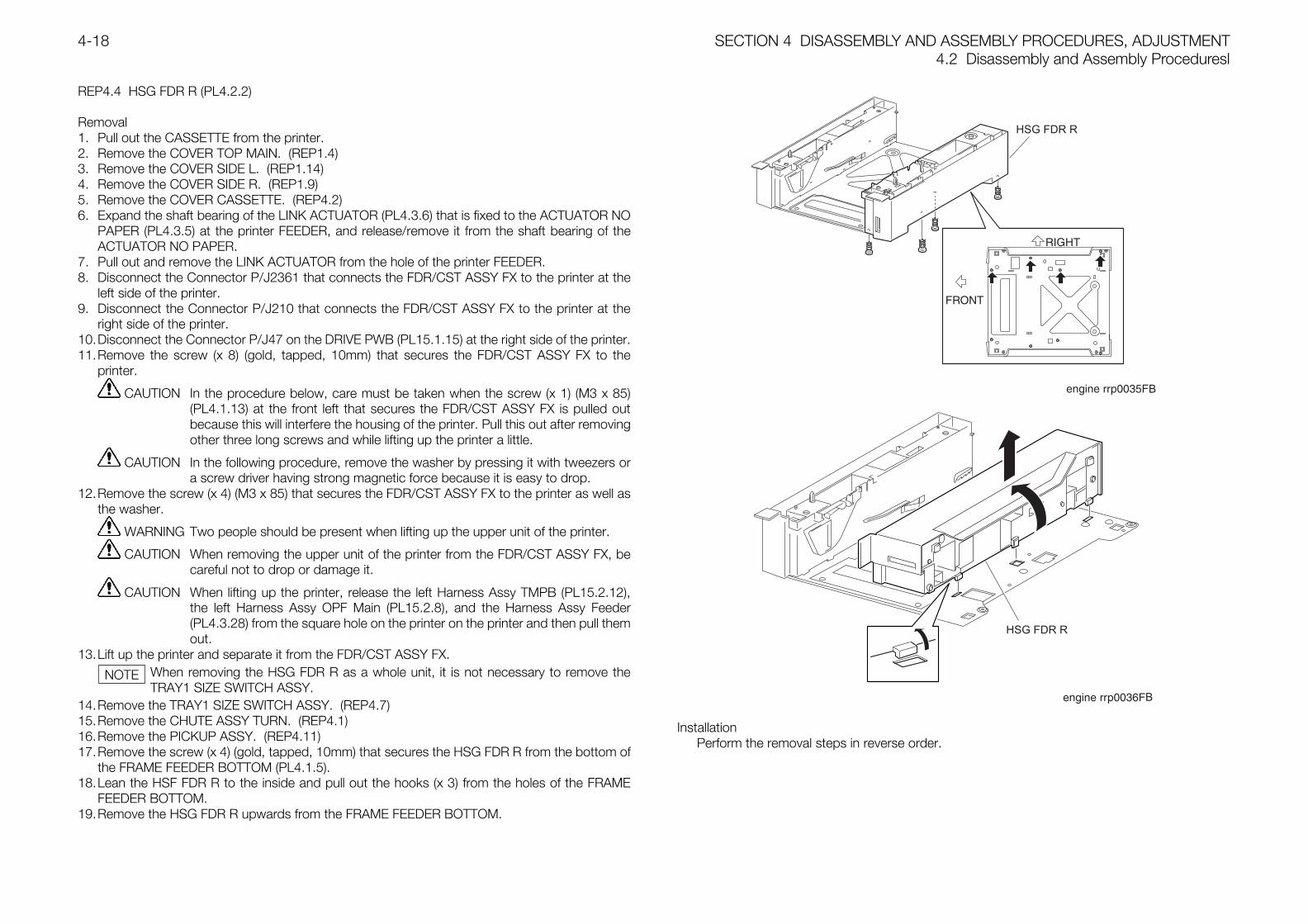
SECTION 4 DISASSEMBLY AND ASSEMBLY PROCEDURES, ADJUSTMENT4.2 Disassembly and Assembly Proceduresl
4-18
REP4.4 HSG FDR R (PL4.2.2)
Removal1. Pull out the CASSETTE from the printer.2. Remove the COVER TOP MAIN. (REP1.4)3. Remove the COVER SIDE L. (REP1.14)4. Remove the COVER SIDE R. (REP1.9)5. Remove the COVER CASSETTE. (REP4.2)6. Expand the shaft bearing of the LINK ACTUATOR (PL4.3.6) that is fixed to the ACTUATOR NO
PAPER (PL4.3.5) at the printer FEEDER, and release/remove it from the shaft bearing of theACTUATOR NO PAPER.
7. Pull out and remove the LINK ACTUATOR from the hole of the printer FEEDER.8. Disconnect the Connector P/J2361 that connects the FDR/CST ASSY FX to the printer at the
left side of the printer.9. Disconnect the Connector P/J210 that connects the FDR/CST ASSY FX to the printer at the
right side of the printer.10.Disconnect the Connector P/J47 on the DRIVE PWB (PL15.1.15) at the right side of the printer.11.Remove the screw (x 8) (gold, tapped, 10mm) that secures the FDR/CST ASSY FX to the
printer.
CAUTION In the procedure below, care must be taken when the screw (x 1) (M3 x 85)(PL4.1.13) at the front left that secures the FDR/CST ASSY FX is pulled outbecause this will interfere the housing of the printer. Pull this out after removingother three long screws and while lifting up the printer a little.
CAUTION In the following procedure, remove the washer by pressing it with tweezers ora screw driver having strong magnetic force because it is easy to drop.
12.Remove the screw (x 4) (M3 x 85) that secures the FDR/CST ASSY FX to the printer as well asthe washer.
WARNING Two people should be present when lifting up the upper unit of the printer.
CAUTION When removing the upper unit of the printer from the FDR/CST ASSY FX, becareful not to drop or damage it.
CAUTION When lifting up the printer, release the left Harness Assy TMPB (PL15.2.12),the left Harness Assy OPF Main (PL15.2.8), and the Harness Assy Feeder(PL4.3.28) from the square hole on the printer on the printer and then pull themout.
13.Lift up the printer and separate it from the FDR/CST ASSY FX.When removing the HSG FDR R as a whole unit, it is not necessary to remove theTRAY1 SIZE SWITCH ASSY.
14.Remove the TRAY1 SIZE SWITCH ASSY. (REP4.7)15.Remove the CHUTE ASSY TURN. (REP4.1)16.Remove the PICKUP ASSY. (REP4.11)17.Remove the screw (x 4) (gold, tapped, 10mm) that secures the HSG FDR R from the bottom of
the FRAME FEEDER BOTTOM (PL4.1.5).18.Lean the HSF FDR R to the inside and pull out the hooks (x 3) from the holes of the FRAME
FEEDER BOTTOM.19.Remove the HSG FDR R upwards from the FRAME FEEDER BOTTOM.
InstallationPerform the removal steps in reverse order.
NOTE
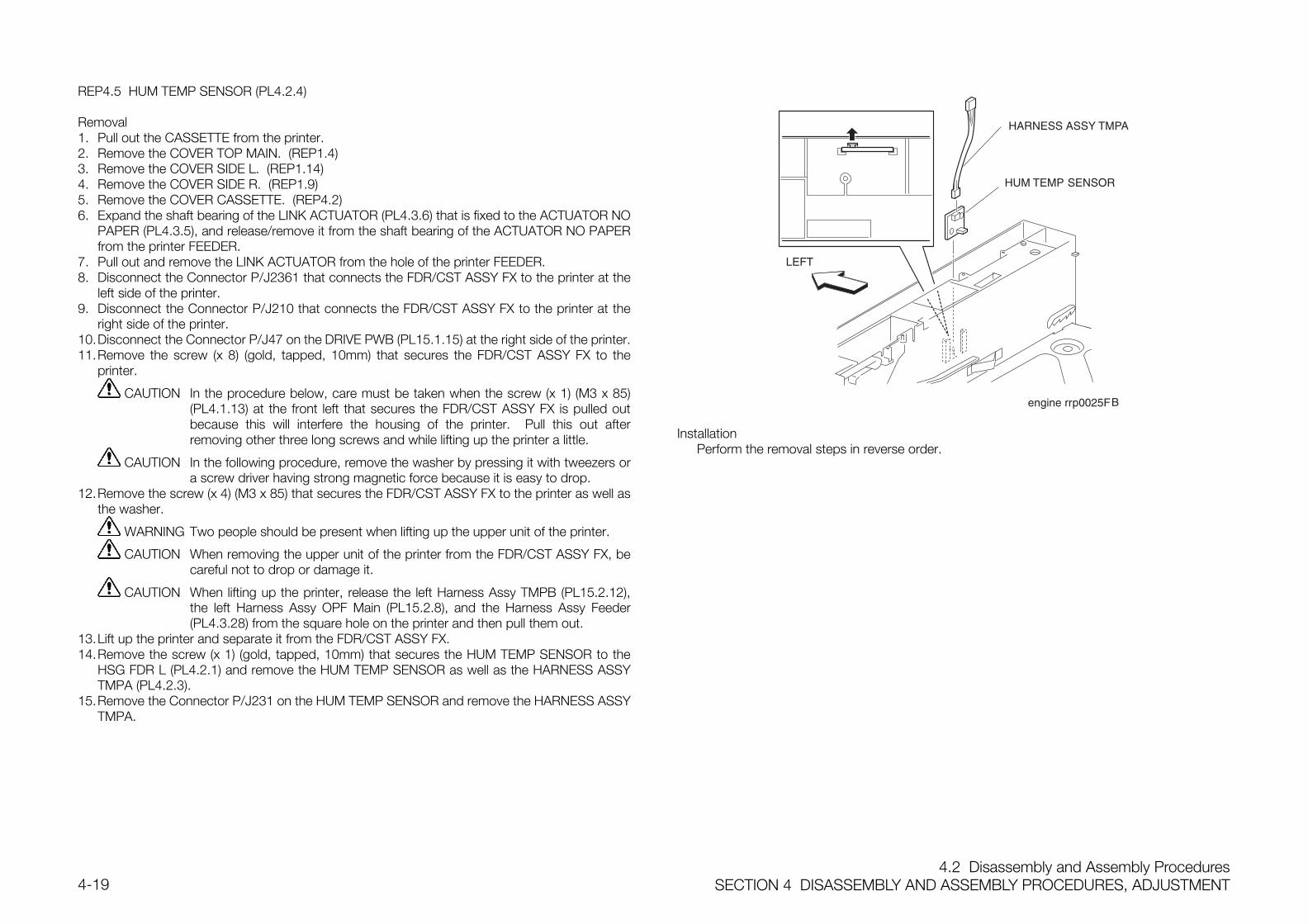
4.2 Disassembly and Assembly ProceduresSECTION 4 DISASSEMBLY AND ASSEMBLY PROCEDURES, ADJUSTMENT4-19
REP4.5 HUM TEMP SENSOR (PL4.2.4)
Removal1. Pull out the CASSETTE from the printer.2. Remove the COVER TOP MAIN. (REP1.4)3. Remove the COVER SIDE L. (REP1.14)4. Remove the COVER SIDE R. (REP1.9)5. Remove the COVER CASSETTE. (REP4.2)6. Expand the shaft bearing of the LINK ACTUATOR (PL4.3.6) that is fixed to the ACTUATOR NO
PAPER (PL4.3.5), and release/remove it from the shaft bearing of the ACTUATOR NO PAPERfrom the printer FEEDER.
7. Pull out and remove the LINK ACTUATOR from the hole of the printer FEEDER.8. Disconnect the Connector P/J2361 that connects the FDR/CST ASSY FX to the printer at the
left side of the printer.9. Disconnect the Connector P/J210 that connects the FDR/CST ASSY FX to the printer at the
right side of the printer.10.Disconnect the Connector P/J47 on the DRIVE PWB (PL15.1.15) at the right side of the printer.11.Remove the screw (x 8) (gold, tapped, 10mm) that secures the FDR/CST ASSY FX to the
printer.
CAUTION In the procedure below, care must be taken when the screw (x 1) (M3 x 85)(PL4.1.13) at the front left that secures the FDR/CST ASSY FX is pulled outbecause this will interfere the housing of the printer. Pull this out afterremoving other three long screws and while lifting up the printer a little.
CAUTION In the following procedure, remove the washer by pressing it with tweezers ora screw driver having strong magnetic force because it is easy to drop.
12.Remove the screw (x 4) (M3 x 85) that secures the FDR/CST ASSY FX to the printer as well asthe washer.
WARNING Two people should be present when lifting up the upper unit of the printer.
CAUTION When removing the upper unit of the printer from the FDR/CST ASSY FX, becareful not to drop or damage it.
CAUTION When lifting up the printer, release the left Harness Assy TMPB (PL15.2.12),the left Harness Assy OPF Main (PL15.2.8), and the Harness Assy Feeder(PL4.3.28) from the square hole on the printer and then pull them out.
13.Lift up the printer and separate it from the FDR/CST ASSY FX.14.Remove the screw (x 1) (gold, tapped, 10mm) that secures the HUM TEMP SENSOR to the
HSG FDR L (PL4.2.1) and remove the HUM TEMP SENSOR as well as the HARNESS ASSYTMPA (PL4.2.3).
15.Remove the Connector P/J231 on the HUM TEMP SENSOR and remove the HARNESS ASSYTMPA.
InstallationPerform the removal steps in reverse order.
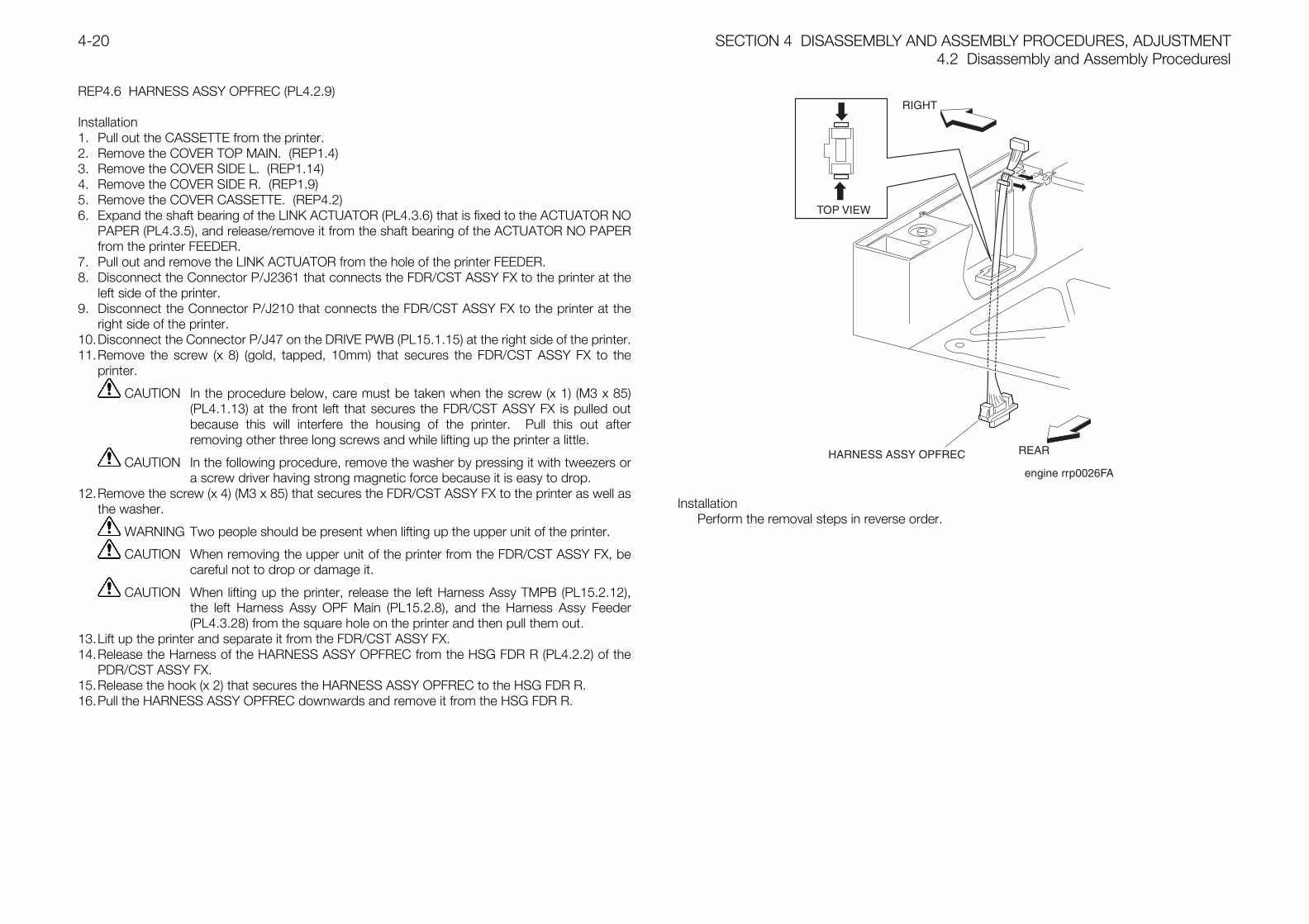
SECTION 4 DISASSEMBLY AND ASSEMBLY PROCEDURES, ADJUSTMENT4.2 Disassembly and Assembly Proceduresl
4-20
REP4.6 HARNESS ASSY OPFREC (PL4.2.9)
Installation1. Pull out the CASSETTE from the printer.2. Remove the COVER TOP MAIN. (REP1.4)3. Remove the COVER SIDE L. (REP1.14)4. Remove the COVER SIDE R. (REP1.9)5. Remove the COVER CASSETTE. (REP4.2)6. Expand the shaft bearing of the LINK ACTUATOR (PL4.3.6) that is fixed to the ACTUATOR NO
PAPER (PL4.3.5), and release/remove it from the shaft bearing of the ACTUATOR NO PAPERfrom the printer FEEDER.
7. Pull out and remove the LINK ACTUATOR from the hole of the printer FEEDER.8. Disconnect the Connector P/J2361 that connects the FDR/CST ASSY FX to the printer at the
left side of the printer.9. Disconnect the Connector P/J210 that connects the FDR/CST ASSY FX to the printer at the
right side of the printer.10.Disconnect the Connector P/J47 on the DRIVE PWB (PL15.1.15) at the right side of the printer.11.Remove the screw (x 8) (gold, tapped, 10mm) that secures the FDR/CST ASSY FX to the
printer.
CAUTION In the procedure below, care must be taken when the screw (x 1) (M3 x 85)(PL4.1.13) at the front left that secures the FDR/CST ASSY FX is pulled outbecause this will interfere the housing of the printer. Pull this out afterremoving other three long screws and while lifting up the printer a little.
CAUTION In the following procedure, remove the washer by pressing it with tweezers ora screw driver having strong magnetic force because it is easy to drop.
12.Remove the screw (x 4) (M3 x 85) that secures the FDR/CST ASSY FX to the printer as well asthe washer.
WARNING Two people should be present when lifting up the upper unit of the printer.
CAUTION When removing the upper unit of the printer from the FDR/CST ASSY FX, becareful not to drop or damage it.
CAUTION When lifting up the printer, release the left Harness Assy TMPB (PL15.2.12),the left Harness Assy OPF Main (PL15.2.8), and the Harness Assy Feeder(PL4.3.28) from the square hole on the printer and then pull them out.
13.Lift up the printer and separate it from the FDR/CST ASSY FX.14.Release the Harness of the HARNESS ASSY OPFREC from the HSG FDR R (PL4.2.2) of the
PDR/CST ASSY FX.15.Release the hook (x 2) that secures the HARNESS ASSY OPFREC to the HSG FDR R.16.Pull the HARNESS ASSY OPFREC downwards and remove it from the HSG FDR R.
InstallationPerform the removal steps in reverse order.
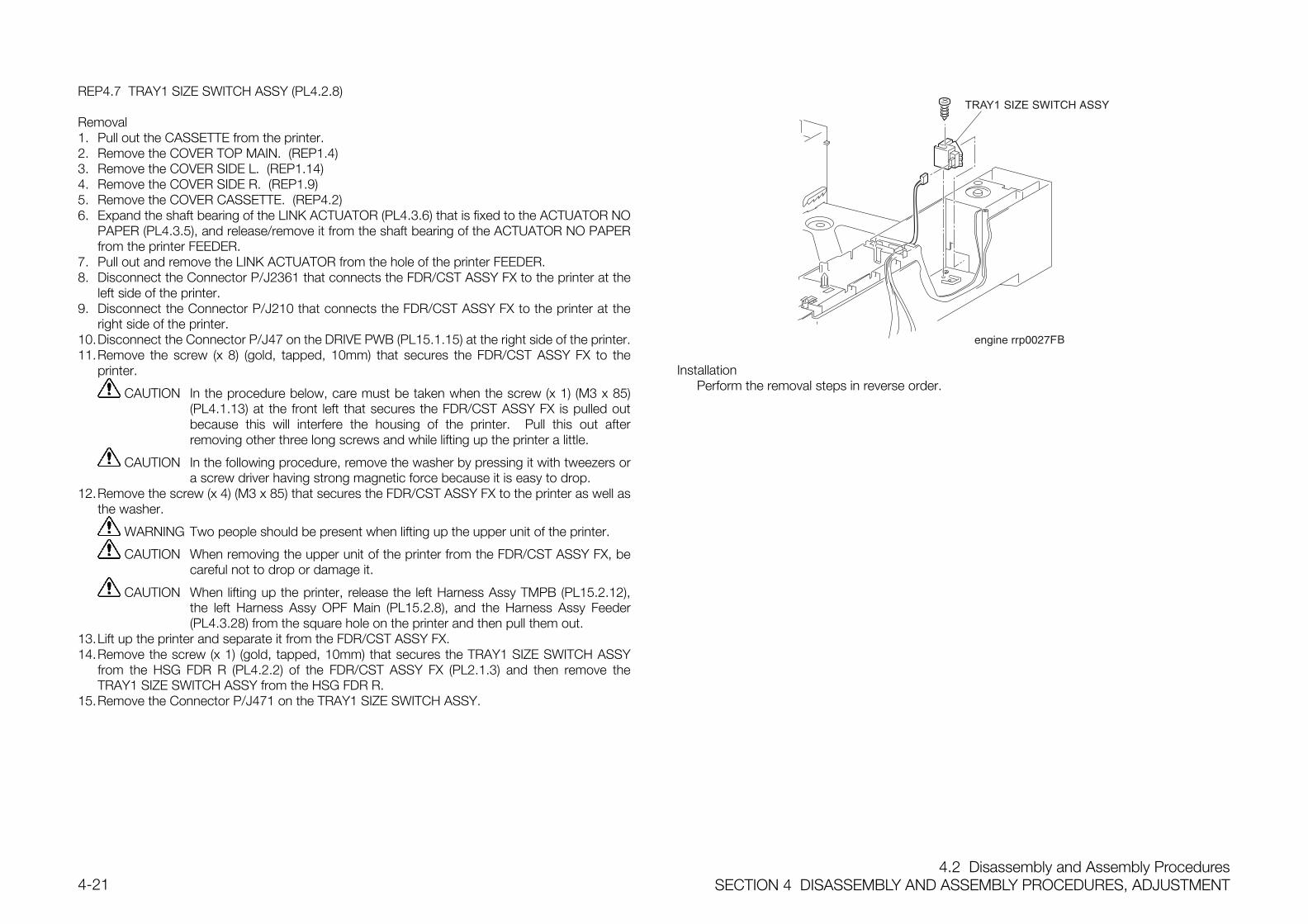
4.2 Disassembly and Assembly ProceduresSECTION 4 DISASSEMBLY AND ASSEMBLY PROCEDURES, ADJUSTMENT4-21
REP4.7 TRAY1 SIZE SWITCH ASSY (PL4.2.8)
Removal1. Pull out the CASSETTE from the printer.2. Remove the COVER TOP MAIN. (REP1.4)3. Remove the COVER SIDE L. (REP1.14)4. Remove the COVER SIDE R. (REP1.9)5. Remove the COVER CASSETTE. (REP4.2)6. Expand the shaft bearing of the LINK ACTUATOR (PL4.3.6) that is fixed to the ACTUATOR NO
PAPER (PL4.3.5), and release/remove it from the shaft bearing of the ACTUATOR NO PAPERfrom the printer FEEDER.
7. Pull out and remove the LINK ACTUATOR from the hole of the printer FEEDER.8. Disconnect the Connector P/J2361 that connects the FDR/CST ASSY FX to the printer at the
left side of the printer.9. Disconnect the Connector P/J210 that connects the FDR/CST ASSY FX to the printer at the
right side of the printer.10.Disconnect the Connector P/J47 on the DRIVE PWB (PL15.1.15) at the right side of the printer.11.Remove the screw (x 8) (gold, tapped, 10mm) that secures the FDR/CST ASSY FX to the
printer.
CAUTION In the procedure below, care must be taken when the screw (x 1) (M3 x 85)(PL4.1.13) at the front left that secures the FDR/CST ASSY FX is pulled outbecause this will interfere the housing of the printer. Pull this out afterremoving other three long screws and while lifting up the printer a little.
CAUTION In the following procedure, remove the washer by pressing it with tweezers ora screw driver having strong magnetic force because it is easy to drop.
12.Remove the screw (x 4) (M3 x 85) that secures the FDR/CST ASSY FX to the printer as well asthe washer.
WARNING Two people should be present when lifting up the upper unit of the printer.
CAUTION When removing the upper unit of the printer from the FDR/CST ASSY FX, becareful not to drop or damage it.
CAUTION When lifting up the printer, release the left Harness Assy TMPB (PL15.2.12),the left Harness Assy OPF Main (PL15.2.8), and the Harness Assy Feeder(PL4.3.28) from the square hole on the printer and then pull them out.
13.Lift up the printer and separate it from the FDR/CST ASSY FX.14.Remove the screw (x 1) (gold, tapped, 10mm) that secures the TRAY1 SIZE SWITCH ASSY
from the HSG FDR R (PL4.2.2) of the FDR/CST ASSY FX (PL2.1.3) and then remove theTRAY1 SIZE SWITCH ASSY from the HSG FDR R.
15.Remove the Connector P/J471 on the TRAY1 SIZE SWITCH ASSY.
InstallationPerform the removal steps in reverse order.
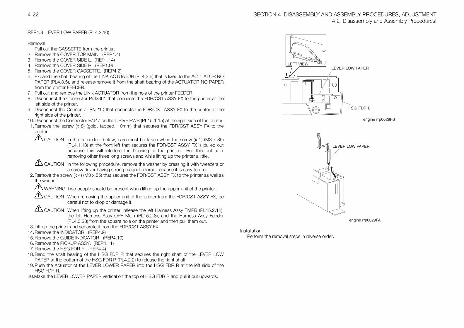
SECTION 4 DISASSEMBLY AND ASSEMBLY PROCEDURES, ADJUSTMENT4.2 Disassembly and Assembly Proceduresl
4-22
REP4.8 LEVER LOW PAPER (PL4.2.10)
Removal1. Pull out the CASSETTE from the printer.2. Remove the COVER TOP MAIN. (REP1.4)3. Remove the COVER SIDE L. (REP1.14)4. Remove the COVER SIDE R. (REP1.9)5. Remove the COVER CASSETTE. (REP4.2)6. Expand the shaft bearing of the LINK ACTUATOR (PL4.3.6) that is fixed to the ACTUATOR NO
PAPER (PL4.3.5), and release/remove it from the shaft bearing of the ACTUATOR NO PAPERfrom the printer FEEDER.
7. Pull out and remove the LINK ACTUATOR from the hole of the printer FEEDER.8. Disconnect the Connector P/J2361 that connects the FDR/CST ASSY FX to the printer at the
left side of the printer.9. Disconnect the Connector P/J210 that connects the FDR/CST ASSY FX to the printer at the
right side of the printer.10.Disconnect the Connector P/J47 on the DRIVE PWB (PL15.1.15) at the right side of the printer.11.Remove the screw (x 8) (gold, tapped, 10mm) that secures the FDR/CST ASSY FX to the
printer.
CAUTION In the procedure below, care must be taken when the screw (x 1) (M3 x 85)(PL4.1.13) at the front left that secures the FDR/CST ASSY FX is pulled outbecause this will interfere the housing of the printer. Pull this out afterremoving other three long screws and while lifting up the printer a little.
CAUTION In the following procedure, remove the washer by pressing it with tweezers ora screw driver having strong magnetic force because it is easy to drop.
12.Remove the screw (x 4) (M3 x 85) that secures the FDR/CST ASSY FX to the printer as well asthe washer.
WARNING Two people should be present when lifting up the upper unit of the printer.
CAUTION When removing the upper unit of the printer from the FDR/CST ASSY FX, becareful not to drop or damage it.
CAUTION When lifting up the printer, release the left Harness Assy TMPB (PL15.2.12),the left Harness Assy OPF Main (PL15.2.8), and the Harness Assy Feeder(PL4.3.28) from the square hole on the printer and then pull them out.
13.Lift up the printer and separate it from the FDR/CST ASSY FX.14.Remove the INDICATOR. (REP4.9)15.Remove the GUIDE INDICATOR. (REP4.10)16.Remove the PICKUP ASSY. (REP4.11)17.Remove the HSG FDR R. (REP4.4)18.Bend the shaft bearing of the HSG FDR R that secures the right shaft of the LEVER LOW
PAPER at the bottom of the HSG FDR R (PL4.2.2) to release the right shaft.19.Push the Actuator of the LEVER LOWER PAPER into the HSG FDR R at the left side of the
HSG FDR R.20.Make the LEVER LOWER PAPER vertical on the top of HSG FDR R and pull it out upwards.
InstallationPerform the removal steps in reverse order.
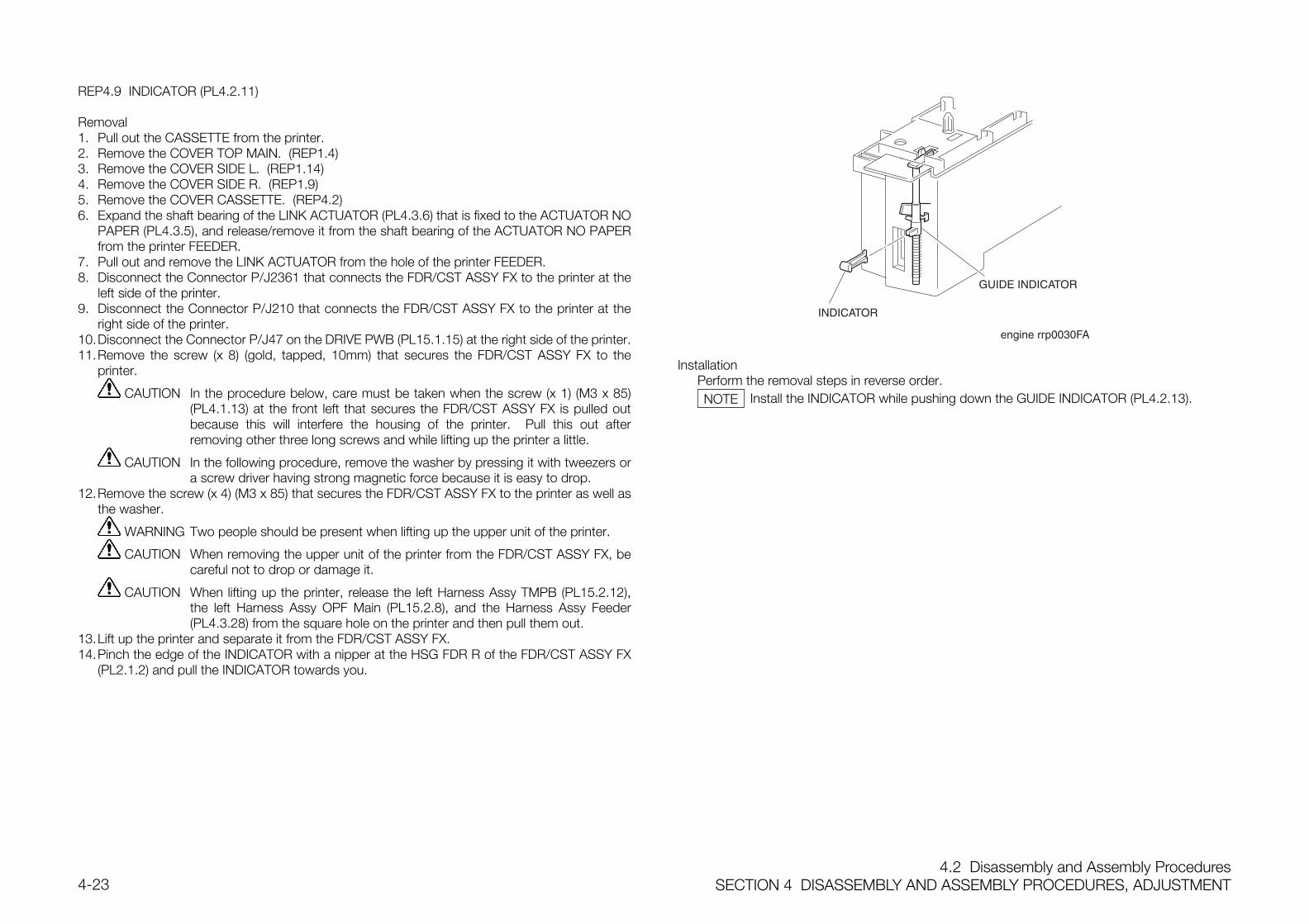
4.2 Disassembly and Assembly ProceduresSECTION 4 DISASSEMBLY AND ASSEMBLY PROCEDURES, ADJUSTMENT4-23
REP4.9 INDICATOR (PL4.2.11)
Removal1. Pull out the CASSETTE from the printer.2. Remove the COVER TOP MAIN. (REP1.4)3. Remove the COVER SIDE L. (REP1.14)4. Remove the COVER SIDE R. (REP1.9)5. Remove the COVER CASSETTE. (REP4.2)6. Expand the shaft bearing of the LINK ACTUATOR (PL4.3.6) that is fixed to the ACTUATOR NO
PAPER (PL4.3.5), and release/remove it from the shaft bearing of the ACTUATOR NO PAPERfrom the printer FEEDER.
7. Pull out and remove the LINK ACTUATOR from the hole of the printer FEEDER.8. Disconnect the Connector P/J2361 that connects the FDR/CST ASSY FX to the printer at the
left side of the printer.9. Disconnect the Connector P/J210 that connects the FDR/CST ASSY FX to the printer at the
right side of the printer.10.Disconnect the Connector P/J47 on the DRIVE PWB (PL15.1.15) at the right side of the printer.11.Remove the screw (x 8) (gold, tapped, 10mm) that secures the FDR/CST ASSY FX to the
printer.
CAUTION In the procedure below, care must be taken when the screw (x 1) (M3 x 85)(PL4.1.13) at the front left that secures the FDR/CST ASSY FX is pulled outbecause this will interfere the housing of the printer. Pull this out afterremoving other three long screws and while lifting up the printer a little.
CAUTION In the following procedure, remove the washer by pressing it with tweezers ora screw driver having strong magnetic force because it is easy to drop.
12.Remove the screw (x 4) (M3 x 85) that secures the FDR/CST ASSY FX to the printer as well asthe washer.
WARNING Two people should be present when lifting up the upper unit of the printer.
CAUTION When removing the upper unit of the printer from the FDR/CST ASSY FX, becareful not to drop or damage it.
CAUTION When lifting up the printer, release the left Harness Assy TMPB (PL15.2.12),the left Harness Assy OPF Main (PL15.2.8), and the Harness Assy Feeder(PL4.3.28) from the square hole on the printer and then pull them out.
13.Lift up the printer and separate it from the FDR/CST ASSY FX.14.Pinch the edge of the INDICATOR with a nipper at the HSG FDR R of the FDR/CST ASSY FX
(PL2.1.2) and pull the INDICATOR towards you.
InstallationPerform the removal steps in reverse order.
Install the INDICATOR while pushing down the GUIDE INDICATOR (PL4.2.13).NOTE
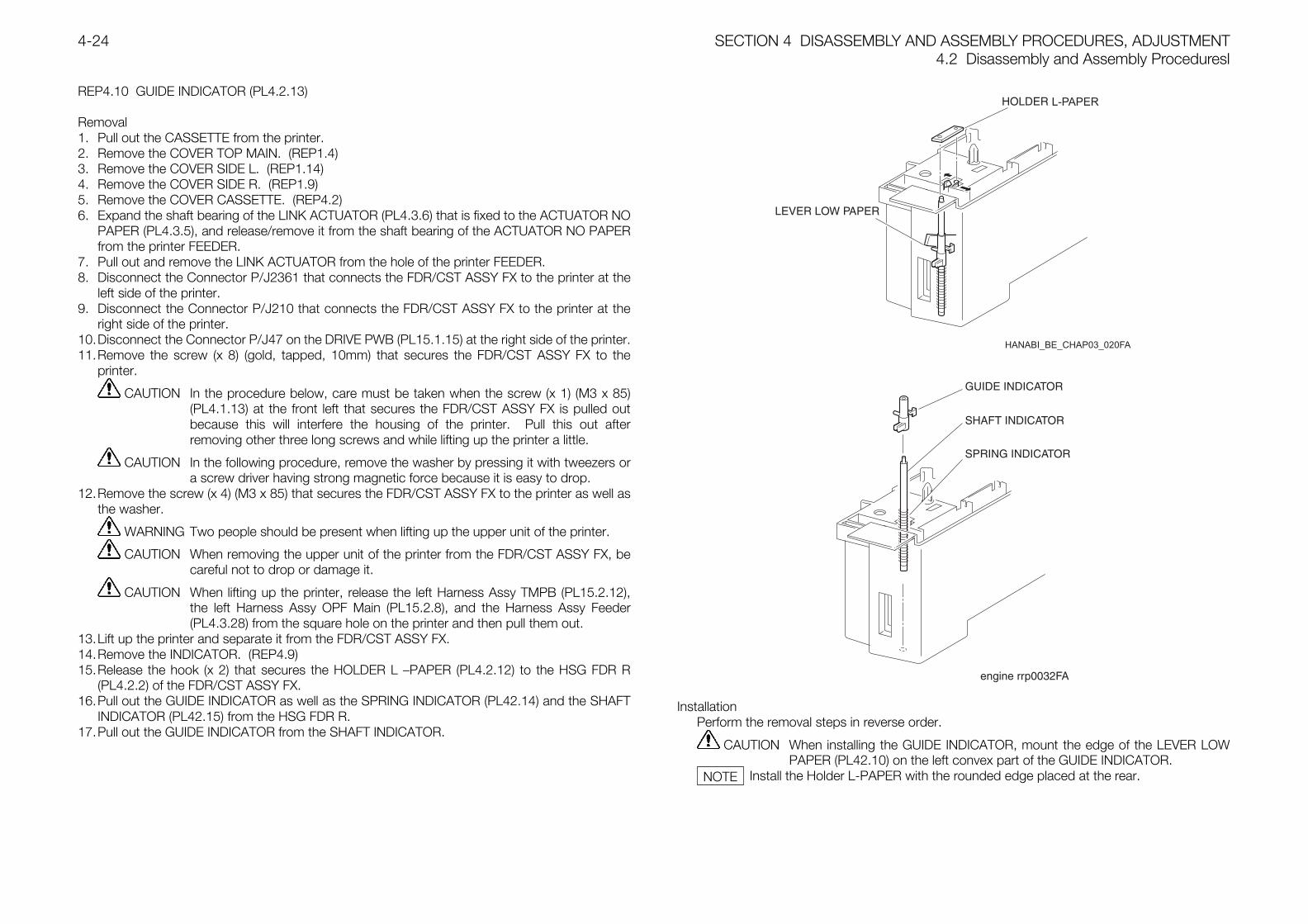
SECTION 4 DISASSEMBLY AND ASSEMBLY PROCEDURES, ADJUSTMENT4.2 Disassembly and Assembly Proceduresl
4-24
REP4.10 GUIDE INDICATOR (PL4.2.13)
Removal1. Pull out the CASSETTE from the printer.2. Remove the COVER TOP MAIN. (REP1.4)3. Remove the COVER SIDE L. (REP1.14)4. Remove the COVER SIDE R. (REP1.9)5. Remove the COVER CASSETTE. (REP4.2)6. Expand the shaft bearing of the LINK ACTUATOR (PL4.3.6) that is fixed to the ACTUATOR NO
PAPER (PL4.3.5), and release/remove it from the shaft bearing of the ACTUATOR NO PAPERfrom the printer FEEDER.
7. Pull out and remove the LINK ACTUATOR from the hole of the printer FEEDER.8. Disconnect the Connector P/J2361 that connects the FDR/CST ASSY FX to the printer at the
left side of the printer.9. Disconnect the Connector P/J210 that connects the FDR/CST ASSY FX to the printer at the
right side of the printer.10.Disconnect the Connector P/J47 on the DRIVE PWB (PL15.1.15) at the right side of the printer.11.Remove the screw (x 8) (gold, tapped, 10mm) that secures the FDR/CST ASSY FX to the
printer.
CAUTION In the procedure below, care must be taken when the screw (x 1) (M3 x 85)(PL4.1.13) at the front left that secures the FDR/CST ASSY FX is pulled outbecause this will interfere the housing of the printer. Pull this out afterremoving other three long screws and while lifting up the printer a little.
CAUTION In the following procedure, remove the washer by pressing it with tweezers ora screw driver having strong magnetic force because it is easy to drop.
12.Remove the screw (x 4) (M3 x 85) that secures the FDR/CST ASSY FX to the printer as well asthe washer.
WARNING Two people should be present when lifting up the upper unit of the printer.
CAUTION When removing the upper unit of the printer from the FDR/CST ASSY FX, becareful not to drop or damage it.
CAUTION When lifting up the printer, release the left Harness Assy TMPB (PL15.2.12),the left Harness Assy OPF Main (PL15.2.8), and the Harness Assy Feeder(PL4.3.28) from the square hole on the printer and then pull them out.
13.Lift up the printer and separate it from the FDR/CST ASSY FX.14.Remove the INDICATOR. (REP4.9)15.Release the hook (x 2) that secures the HOLDER L —PAPER (PL4.2.12) to the HSG FDR R
(PL4.2.2) of the FDR/CST ASSY FX.16.Pull out the GUIDE INDICATOR as well as the SPRING INDICATOR (PL42.14) and the SHAFT
INDICATOR (PL42.15) from the HSG FDR R.17.Pull out the GUIDE INDICATOR from the SHAFT INDICATOR.
InstallationPerform the removal steps in reverse order.
CAUTION When installing the GUIDE INDICATOR, mount the edge of the LEVER LOWPAPER (PL42.10) on the left convex part of the GUIDE INDICATOR.
Install the Holder L-PAPER with the rounded edge placed at the rear.NOTE
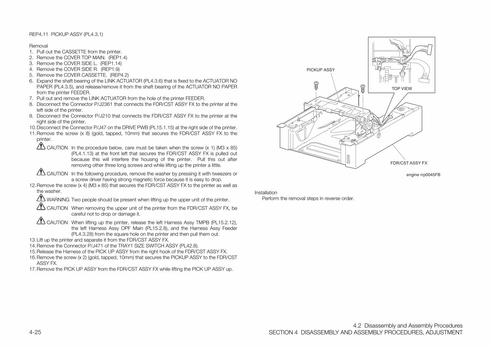
4.2 Disassembly and Assembly ProceduresSECTION 4 DISASSEMBLY AND ASSEMBLY PROCEDURES, ADJUSTMENT4-25
REP4.11 PICKUP ASSY (PL4.3.1)
Removal1. Pull out the CASSETTE from the printer.2. Remove the COVER TOP MAIN. (REP1.4)3. Remove the COVER SIDE L. (REP1.14)4. Remove the COVER SIDE R. (REP1.9)5. Remove the COVER CASSETTE. (REP4.2)6. Expand the shaft bearing of the LINK ACTUATOR (PL4.3.6) that is fixed to the ACTUATOR NO
PAPER (PL4.3.5), and release/remove it from the shaft bearing of the ACTUATOR NO PAPERfrom the printer FEEDER.
7. Pull out and remove the LINK ACTUATOR from the hole of the printer FEEDER.8. Disconnect the Connector P/J2361 that connects the FDR/CST ASSY FX to the printer at the
left side of the printer.9. Disconnect the Connector P/J210 that connects the FDR/CST ASSY FX to the printer at the
right side of the printer.10.Disconnect the Connector P/J47 on the DRIVE PWB (PL15.1.15) at the right side of the printer.11.Remove the screw (x 8) (gold, tapped, 10mm) that secures the FDR/CST ASSY FX to the
printer.
CAUTION In the procedure below, care must be taken when the screw (x 1) (M3 x 85)(PL4.1.13) at the front left that secures the FDR/CST ASSY FX is pulled outbecause this will interfere the housing of the printer. Pull this out afterremoving other three long screws and while lifting up the printer a little.
CAUTION In the following procedure, remove the washer by pressing it with tweezers ora screw driver having strong magnetic force because it is easy to drop.
12.Remove the screw (x 4) (M3 x 85) that secures the FDR/CST ASSY FX to the printer as well asthe washer.
WARNING Two people should be present when lifting up the upper unit of the printer.
CAUTION When removing the upper unit of the printer from the FDR/CST ASSY FX, becareful not to drop or damage it.
CAUTION When lifting up the printer, release the left Harness Assy TMPB (PL15.2.12),the left Harness Assy OPF Main (PL15.2.8), and the Harness Assy Feeder(PL4.3.28) from the square hole on the printer and then pull them out.
13.Lift up the printer and separate it from the FDR/CST ASSY FX.14.Remove the Connector P/J471 of the TRAY1 SIZE SWITCH ASSY (PL42.8).15.Release the Harness of the PICK UP ASSY from the right hook of the FDR/CST ASSY FX.16.Remove the screw (x 2) (gold, tapped, 10mm) that secures the PICKUP ASSY to the FDR/CST
ASSY FX.17.Remove the PICK UP ASSY from the FDR/CST ASSY FX while lifting the PICK UP ASSY up.
B
FDR/CST ASSY FX
InstallationPerform the removal steps in reverse order.
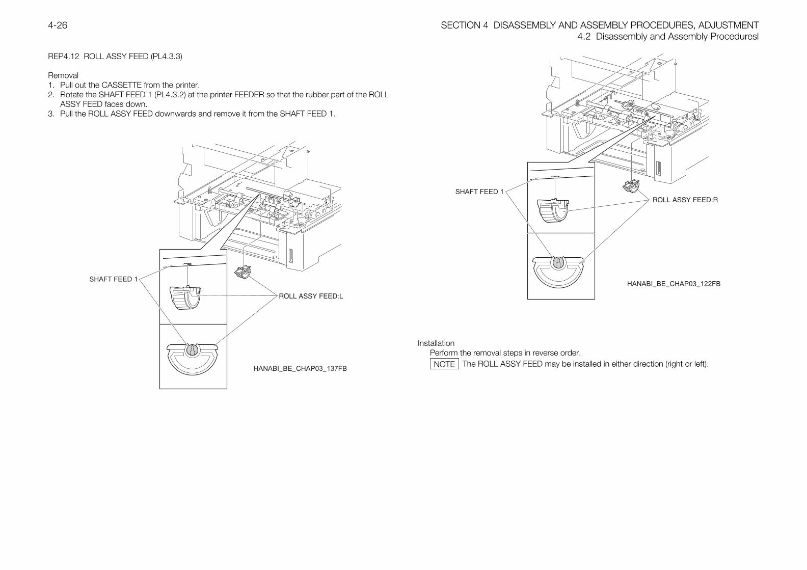
SECTION 4 DISASSEMBLY AND ASSEMBLY PROCEDURES, ADJUSTMENT4.2 Disassembly and Assembly Proceduresl
4-26
REP4.12 ROLL ASSY FEED (PL4.3.3)
Removal1. Pull out the CASSETTE from the printer.2. Rotate the SHAFT FEED 1 (PL4.3.2) at the printer FEEDER so that the rubber part of the ROLL
ASSY FEED faces down.3. Pull the ROLL ASSY FEED downwards and remove it from the SHAFT FEED 1.
HANABI_BE_CHAP03_137FB
HANABI_BE_CHAP03_122FB
InstallationPerform the removal steps in reverse order.
The ROLL ASSY FEED may be installed in either direction (right or left).NOTE
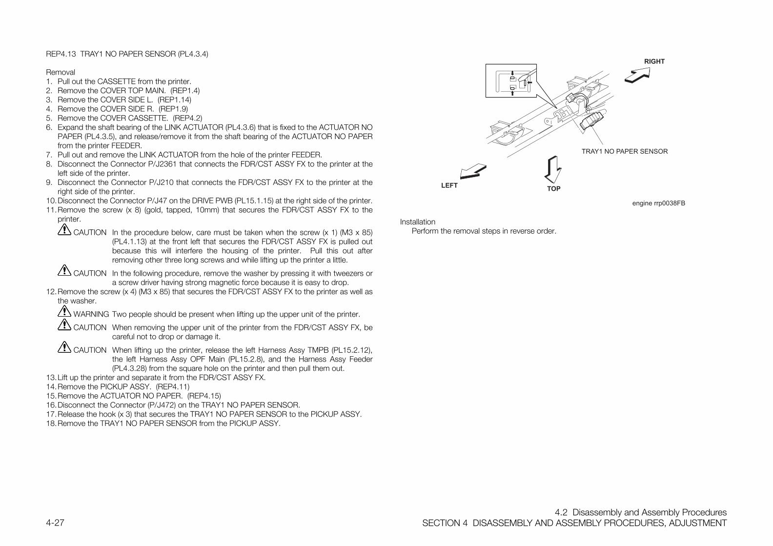
4.2 Disassembly and Assembly ProceduresSECTION 4 DISASSEMBLY AND ASSEMBLY PROCEDURES, ADJUSTMENT4-27
REP4.13 TRAY1 NO PAPER SENSOR (PL4.3.4)
Removal1. Pull out the CASSETTE from the printer.2. Remove the COVER TOP MAIN. (REP1.4)3. Remove the COVER SIDE L. (REP1.14)4. Remove the COVER SIDE R. (REP1.9)5. Remove the COVER CASSETTE. (REP4.2)6. Expand the shaft bearing of the LINK ACTUATOR (PL4.3.6) that is fixed to the ACTUATOR NO
PAPER (PL4.3.5), and release/remove it from the shaft bearing of the ACTUATOR NO PAPERfrom the printer FEEDER.
7. Pull out and remove the LINK ACTUATOR from the hole of the printer FEEDER.8. Disconnect the Connector P/J2361 that connects the FDR/CST ASSY FX to the printer at the
left side of the printer.9. Disconnect the Connector P/J210 that connects the FDR/CST ASSY FX to the printer at the
right side of the printer.10.Disconnect the Connector P/J47 on the DRIVE PWB (PL15.1.15) at the right side of the printer.11.Remove the screw (x 8) (gold, tapped, 10mm) that secures the FDR/CST ASSY FX to the
printer.
CAUTION In the procedure below, care must be taken when the screw (x 1) (M3 x 85)(PL4.1.13) at the front left that secures the FDR/CST ASSY FX is pulled outbecause this will interfere the housing of the printer. Pull this out afterremoving other three long screws and while lifting up the printer a little.
CAUTION In the following procedure, remove the washer by pressing it with tweezers ora screw driver having strong magnetic force because it is easy to drop.
12.Remove the screw (x 4) (M3 x 85) that secures the FDR/CST ASSY FX to the printer as well asthe washer.
WARNING Two people should be present when lifting up the upper unit of the printer.
CAUTION When removing the upper unit of the printer from the FDR/CST ASSY FX, becareful not to drop or damage it.
CAUTION When lifting up the printer, release the left Harness Assy TMPB (PL15.2.12),the left Harness Assy OPF Main (PL15.2.8), and the Harness Assy Feeder(PL4.3.28) from the square hole on the printer and then pull them out.
13.Lift up the printer and separate it from the FDR/CST ASSY FX.14.Remove the PICKUP ASSY. (REP4.11)15.Remove the ACTUATOR NO PAPER. (REP4.15)16.Disconnect the Connector (P/J472) on the TRAY1 NO PAPER SENSOR.17.Release the hook (x 3) that secures the TRAY1 NO PAPER SENSOR to the PICKUP ASSY.18.Remove the TRAY1 NO PAPER SENSOR from the PICKUP ASSY.
LEFT
RIGHT
TOP
engine rrp0038FB
TRAY1 NO PAPER SENSOR
InstallationPerform the removal steps in reverse order.
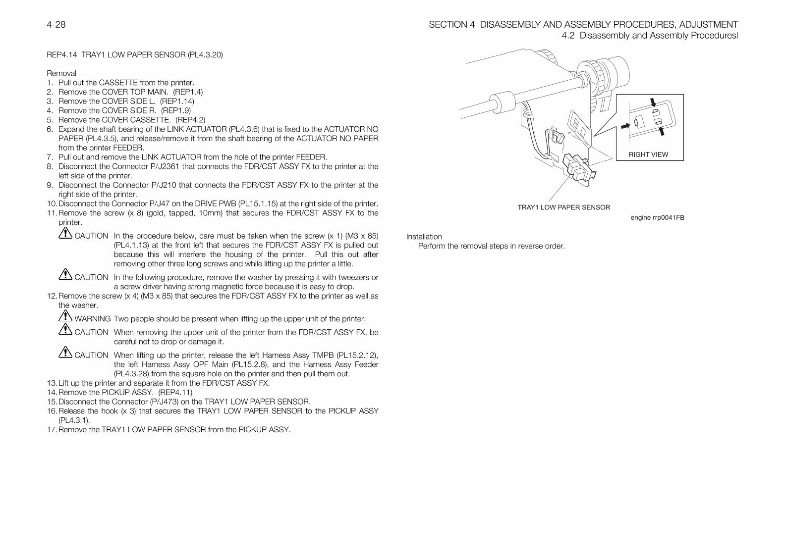
SECTION 4 DISASSEMBLY AND ASSEMBLY PROCEDURES, ADJUSTMENT4.2 Disassembly and Assembly Proceduresl
4-28
REP4.14 TRAY1 LOW PAPER SENSOR (PL4.3.20)
Removal1. Pull out the CASSETTE from the printer.2. Remove the COVER TOP MAIN. (REP1.4)3. Remove the COVER SIDE L. (REP1.14)4. Remove the COVER SIDE R. (REP1.9)5. Remove the COVER CASSETTE. (REP4.2)6. Expand the shaft bearing of the LINK ACTUATOR (PL4.3.6) that is fixed to the ACTUATOR NO
PAPER (PL4.3.5), and release/remove it from the shaft bearing of the ACTUATOR NO PAPERfrom the printer FEEDER.
7. Pull out and remove the LINK ACTUATOR from the hole of the printer FEEDER.8. Disconnect the Connector P/J2361 that connects the FDR/CST ASSY FX to the printer at the
left side of the printer.9. Disconnect the Connector P/J210 that connects the FDR/CST ASSY FX to the printer at the
right side of the printer.10.Disconnect the Connector P/J47 on the DRIVE PWB (PL15.1.15) at the right side of the printer.11.Remove the screw (x 8) (gold, tapped, 10mm) that secures the FDR/CST ASSY FX to the
printer.
CAUTION In the procedure below, care must be taken when the screw (x 1) (M3 x 85)(PL4.1.13) at the front left that secures the FDR/CST ASSY FX is pulled outbecause this will interfere the housing of the printer. Pull this out afterremoving other three long screws and while lifting up the printer a little.
CAUTION In the following procedure, remove the washer by pressing it with tweezers ora screw driver having strong magnetic force because it is easy to drop.
12.Remove the screw (x 4) (M3 x 85) that secures the FDR/CST ASSY FX to the printer as well asthe washer.
WARNING Two people should be present when lifting up the upper unit of the printer.
CAUTION When removing the upper unit of the printer from the FDR/CST ASSY FX, becareful not to drop or damage it.
CAUTION When lifting up the printer, release the left Harness Assy TMPB (PL15.2.12),the left Harness Assy OPF Main (PL15.2.8), and the Harness Assy Feeder(PL4.3.28) from the square hole on the printer and then pull them out.
13.Lift up the printer and separate it from the FDR/CST ASSY FX.14.Remove the PICKUP ASSY. (REP4.11)15.Disconnect the Connector (P/J473) on the TRAY1 LOW PAPER SENSOR.16. Release the hook (x 3) that secures the TRAY1 LOW PAPER SENSOR to the PICKUP ASSY
(PL4.3.1).17.Remove the TRAY1 LOW PAPER SENSOR from the PICKUP ASSY.
TRAY1 LOW PAPER SENSOR
B
InstallationPerform the removal steps in reverse order.
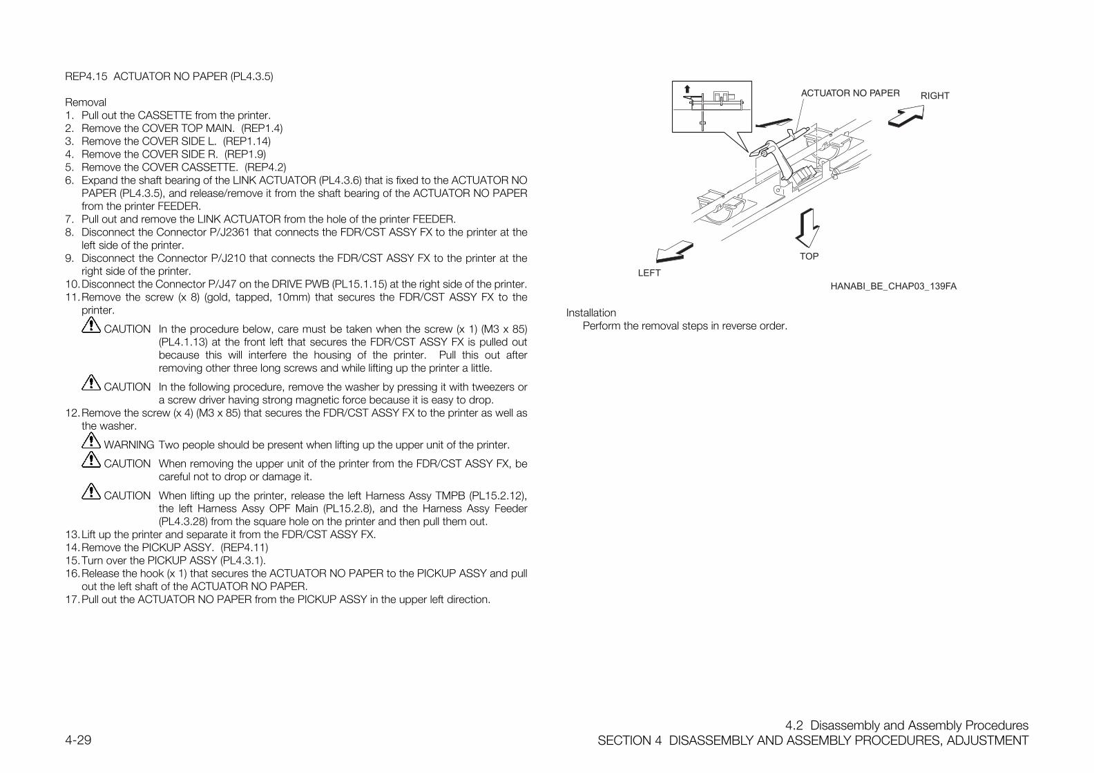
4.2 Disassembly and Assembly ProceduresSECTION 4 DISASSEMBLY AND ASSEMBLY PROCEDURES, ADJUSTMENT4-29
REP4.15 ACTUATOR NO PAPER (PL4.3.5)
Removal1. Pull out the CASSETTE from the printer.2. Remove the COVER TOP MAIN. (REP1.4)3. Remove the COVER SIDE L. (REP1.14)4. Remove the COVER SIDE R. (REP1.9)5. Remove the COVER CASSETTE. (REP4.2)6. Expand the shaft bearing of the LINK ACTUATOR (PL4.3.6) that is fixed to the ACTUATOR NO
PAPER (PL4.3.5), and release/remove it from the shaft bearing of the ACTUATOR NO PAPERfrom the printer FEEDER.
7. Pull out and remove the LINK ACTUATOR from the hole of the printer FEEDER.8. Disconnect the Connector P/J2361 that connects the FDR/CST ASSY FX to the printer at the
left side of the printer.9. Disconnect the Connector P/J210 that connects the FDR/CST ASSY FX to the printer at the
right side of the printer.10.Disconnect the Connector P/J47 on the DRIVE PWB (PL15.1.15) at the right side of the printer.11.Remove the screw (x 8) (gold, tapped, 10mm) that secures the FDR/CST ASSY FX to the
printer.
CAUTION In the procedure below, care must be taken when the screw (x 1) (M3 x 85)(PL4.1.13) at the front left that secures the FDR/CST ASSY FX is pulled outbecause this will interfere the housing of the printer. Pull this out afterremoving other three long screws and while lifting up the printer a little.
CAUTION In the following procedure, remove the washer by pressing it with tweezers ora screw driver having strong magnetic force because it is easy to drop.
12.Remove the screw (x 4) (M3 x 85) that secures the FDR/CST ASSY FX to the printer as well asthe washer.
WARNING Two people should be present when lifting up the upper unit of the printer.
CAUTION When removing the upper unit of the printer from the FDR/CST ASSY FX, becareful not to drop or damage it.
CAUTION When lifting up the printer, release the left Harness Assy TMPB (PL15.2.12),the left Harness Assy OPF Main (PL15.2.8), and the Harness Assy Feeder(PL4.3.28) from the square hole on the printer and then pull them out.
13.Lift up the printer and separate it from the FDR/CST ASSY FX.14.Remove the PICKUP ASSY. (REP4.11)15.Turn over the PICKUP ASSY (PL4.3.1).16.Release the hook (x 1) that secures the ACTUATOR NO PAPER to the PICKUP ASSY and pull
out the left shaft of the ACTUATOR NO PAPER.17.Pull out the ACTUATOR NO PAPER from the PICKUP ASSY in the upper left direction.
LEFT
TOP
RIGHT
HANABI_BE_CHAP03_139FA
InstallationPerform the removal steps in reverse order.
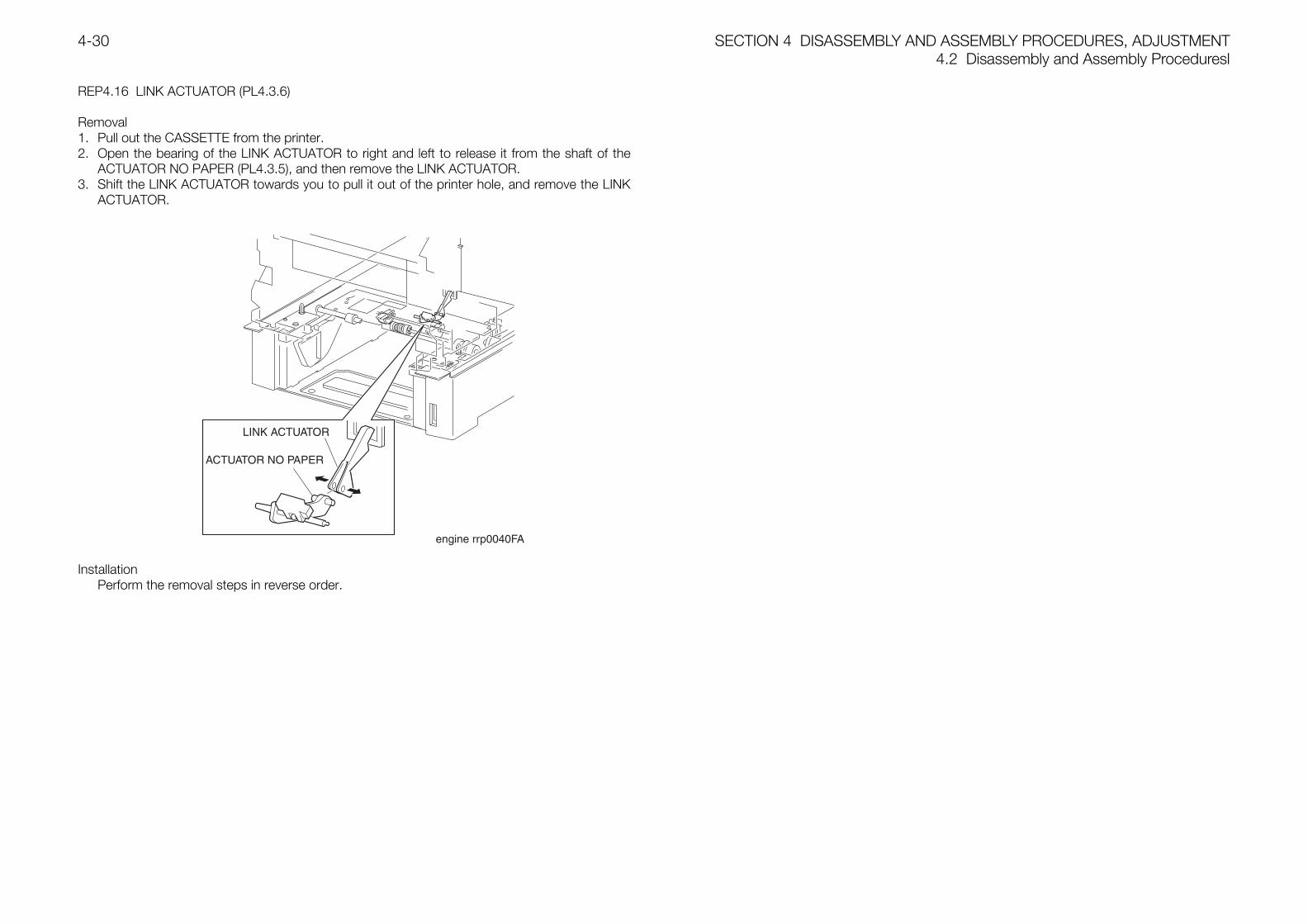
SECTION 4 DISASSEMBLY AND ASSEMBLY PROCEDURES, ADJUSTMENT4.2 Disassembly and Assembly Proceduresl
4-30
REP4.16 LINK ACTUATOR (PL4.3.6)
Removal1. Pull out the CASSETTE from the printer.2. Open the bearing of the LINK ACTUATOR to right and left to release it from the shaft of the
ACTUATOR NO PAPER (PL4.3.5), and then remove the LINK ACTUATOR.3. Shift the LINK ACTUATOR towards you to pull it out of the printer hole, and remove the LINK
ACTUATOR.
InstallationPerform the removal steps in reverse order.
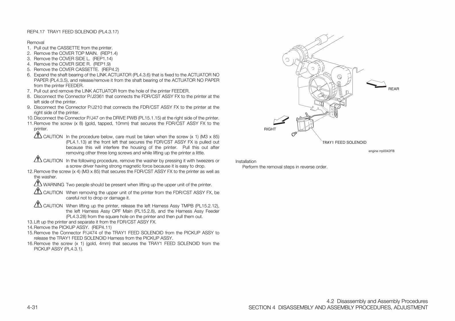
4.2 Disassembly and Assembly ProceduresSECTION 4 DISASSEMBLY AND ASSEMBLY PROCEDURES, ADJUSTMENT4-31
REP4.17 TRAY1 FEED SOLENOID (PL4.3.17)
Removal1. Pull out the CASSETTE from the printer.2. Remove the COVER TOP MAIN. (REP1.4)3. Remove the COVER SIDE L. (REP1.14)4. Remove the COVER SIDE R. (REP1.9)5. Remove the COVER CASSETTE. (REP4.2)6. Expand the shaft bearing of the LINK ACTUATOR (PL4.3.6) that is fixed to the ACTUATOR NO
PAPER (PL4.3.5), and release/remove it from the shaft bearing of the ACTUATOR NO PAPERfrom the printer FEEDER.
7. Pull out and remove the LINK ACTUATOR from the hole of the printer FEEDER.8. Disconnect the Connector P/J2361 that connects the FDR/CST ASSY FX to the printer at the
left side of the printer.9. Disconnect the Connector P/J210 that connects the FDR/CST ASSY FX to the printer at the
right side of the printer.10.Disconnect the Connector P/J47 on the DRIVE PWB (PL15.1.15) at the right side of the printer.11.Remove the screw (x 8) (gold, tapped, 10mm) that secures the FDR/CST ASSY FX to the
printer.
CAUTION In the procedure below, care must be taken when the screw (x 1) (M3 x 85)(PL4.1.13) at the front left that secures the FDR/CST ASSY FX is pulled outbecause this will interfere the housing of the printer. Pull this out afterremoving other three long screws and while lifting up the printer a little.
CAUTION In the following procedure, remove the washer by pressing it with tweezers ora screw driver having strong magnetic force because it is easy to drop.
12.Remove the screw (x 4) (M3 x 85) that secures the FDR/CST ASSY FX to the printer as well asthe washer.
WARNING Two people should be present when lifting up the upper unit of the printer.
CAUTION When removing the upper unit of the printer from the FDR/CST ASSY FX, becareful not to drop or damage it.
CAUTION When lifting up the printer, release the left Harness Assy TMPB (PL15.2.12),the left Harness Assy OPF Main (PL15.2.8), and the Harness Assy Feeder(PL4.3.28) from the square hole on the printer and then pull them out.
13.Lift up the printer and separate it from the FDR/CST ASSY FX.14.Remove the PICKUP ASSY. (REP4.11)15.Remove the Connector P/J474 of the TRAY1 FEED SOLENOID from the PICKUP ASSY to
release the TRAY1 FEED SOLENOID Harness from the PICKUP ASSY.16.Remove the screw (x 1) (gold, 4mm) that secures the TRAY1 FEED SOLENOID from the
PICKUP ASSY (PL4.3.1).
engine rrp0042FB
InstallationPerform the removal steps in reverse order.
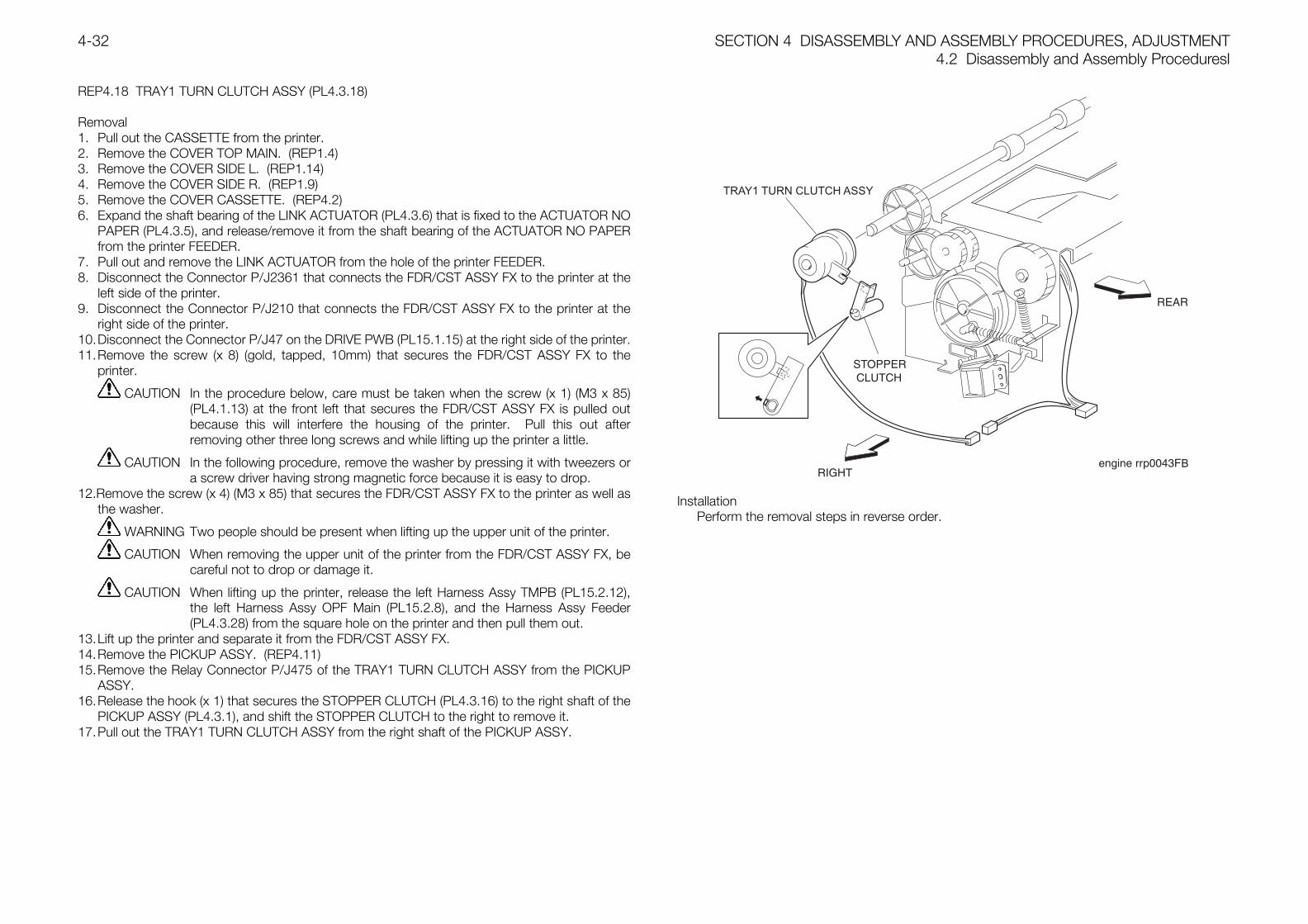
SECTION 4 DISASSEMBLY AND ASSEMBLY PROCEDURES, ADJUSTMENT4.2 Disassembly and Assembly Proceduresl
4-32
REP4.18 TRAY1 TURN CLUTCH ASSY (PL4.3.18)
Removal1. Pull out the CASSETTE from the printer.2. Remove the COVER TOP MAIN. (REP1.4)3. Remove the COVER SIDE L. (REP1.14)4. Remove the COVER SIDE R. (REP1.9)5. Remove the COVER CASSETTE. (REP4.2)6. Expand the shaft bearing of the LINK ACTUATOR (PL4.3.6) that is fixed to the ACTUATOR NO
PAPER (PL4.3.5), and release/remove it from the shaft bearing of the ACTUATOR NO PAPERfrom the printer FEEDER.
7. Pull out and remove the LINK ACTUATOR from the hole of the printer FEEDER.8. Disconnect the Connector P/J2361 that connects the FDR/CST ASSY FX to the printer at the
left side of the printer.9. Disconnect the Connector P/J210 that connects the FDR/CST ASSY FX to the printer at the
right side of the printer.10.Disconnect the Connector P/J47 on the DRIVE PWB (PL15.1.15) at the right side of the printer.11.Remove the screw (x 8) (gold, tapped, 10mm) that secures the FDR/CST ASSY FX to the
printer.
CAUTION In the procedure below, care must be taken when the screw (x 1) (M3 x 85)(PL4.1.13) at the front left that secures the FDR/CST ASSY FX is pulled outbecause this will interfere the housing of the printer. Pull this out afterremoving other three long screws and while lifting up the printer a little.
CAUTION In the following procedure, remove the washer by pressing it with tweezers ora screw driver having strong magnetic force because it is easy to drop.
12.Remove the screw (x 4) (M3 x 85) that secures the FDR/CST ASSY FX to the printer as well asthe washer.
WARNING Two people should be present when lifting up the upper unit of the printer.
CAUTION When removing the upper unit of the printer from the FDR/CST ASSY FX, becareful not to drop or damage it.
CAUTION When lifting up the printer, release the left Harness Assy TMPB (PL15.2.12),the left Harness Assy OPF Main (PL15.2.8), and the Harness Assy Feeder(PL4.3.28) from the square hole on the printer and then pull them out.
13.Lift up the printer and separate it from the FDR/CST ASSY FX.14.Remove the PICKUP ASSY. (REP4.11)15.Remove the Relay Connector P/J475 of the TRAY1 TURN CLUTCH ASSY from the PICKUP
ASSY.16.Release the hook (x 1) that secures the STOPPER CLUTCH (PL4.3.16) to the right shaft of the
PICKUP ASSY (PL4.3.1), and shift the STOPPER CLUTCH to the right to remove it.17.Pull out the TRAY1 TURN CLUTCH ASSY from the right shaft of the PICKUP ASSY.
TRAY1 TURN CLUTCH ASSY
B
InstallationPerform the removal steps in reverse order.
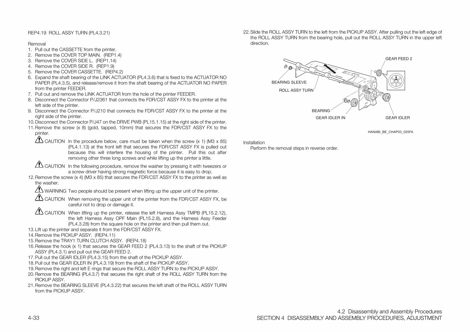
4.2 Disassembly and Assembly ProceduresSECTION 4 DISASSEMBLY AND ASSEMBLY PROCEDURES, ADJUSTMENT4-33
REP4.19 ROLL ASSY TURN (PL4.3.21)
Removal1. Pull out the CASSETTE from the printer.2. Remove the COVER TOP MAIN. (REP1.4)3. Remove the COVER SIDE L. (REP1.14)4. Remove the COVER SIDE R. (REP1.9)5. Remove the COVER CASSETTE. (REP4.2)6. Expand the shaft bearing of the LINK ACTUATOR (PL4.3.6) that is fixed to the ACTUATOR NO
PAPER (PL4.3.5), and release/remove it from the shaft bearing of the ACTUATOR NO PAPERfrom the printer FEEDER.
7. Pull out and remove the LINK ACTUATOR from the hole of the printer FEEDER.8. Disconnect the Connector P/J2361 that connects the FDR/CST ASSY FX to the printer at the
left side of the printer.9. Disconnect the Connector P/J210 that connects the FDR/CST ASSY FX to the printer at the
right side of the printer.10.Disconnect the Connector P/J47 on the DRIVE PWB (PL15.1.15) at the right side of the printer.11.Remove the screw (x 8) (gold, tapped, 10mm) that secures the FDR/CST ASSY FX to the
printer.
CAUTION In the procedure below, care must be taken when the screw (x 1) (M3 x 85)(PL4.1.13) at the front left that secures the FDR/CST ASSY FX is pulled outbecause this will interfere the housing of the printer. Pull this out afterremoving other three long screws and while lifting up the printer a little.
CAUTION In the following procedure, remove the washer by pressing it with tweezers ora screw driver having strong magnetic force because it is easy to drop.
12.Remove the screw (x 4) (M3 x 85) that secures the FDR/CST ASSY FX to the printer as well asthe washer.
WARNING Two people should be present when lifting up the upper unit of the printer.
CAUTION When removing the upper unit of the printer from the FDR/CST ASSY FX, becareful not to drop or damage it.
CAUTION When lifting up the printer, release the left Harness Assy TMPB (PL15.2.12),the left Harness Assy OPF Main (PL15.2.8), and the Harness Assy Feeder(PL4.3.28) from the square hole on the printer and then pull them out.
13.Lift up the printer and separate it from the FDR/CST ASSY FX.14.Remove the PICKUP ASSY. (REP4.11)15.Remove the TRAY1 TURN CLUTCH ASSY. (REP4.18)16.Release the hook (x 1) that secures the GEAR FEED 2 (PL4.3.13) to the shaft of the PICKUP
ASSY (PL4.3.1) and pull out the GEAR FEED 2.17.Pull out the GEAR IDLER (PL4.3.15) from the shaft of the PICKUP ASSY.18.Pull out the GEAR IDLER IN (PL4.3.19) from the shaft of the PICKUP ASSY.19.Remove the right and left E rings that secure the ROLL ASSY TURN to the PICKUP ASSY.20. Remove the BEARING (PL4.3.7) that secures the right shaft of the ROLL ASSY TURN from the
PICKUP ASSY.21.Remove the BEARING SLEEVE (PL4.3.22) that secures the left shaft of the ROLL ASSY TURN
from the PICKUP ASSY.
22.Slide the ROLL ASSY TURN to the left from the PICKUP ASSY. After pulling out the left edge ofthe ROLL ASSY TURN from the bearing hole, pull out the ROLL ASSY TURN in the upper leftdirection.
InstallationPerform the removal steps in reverse order.
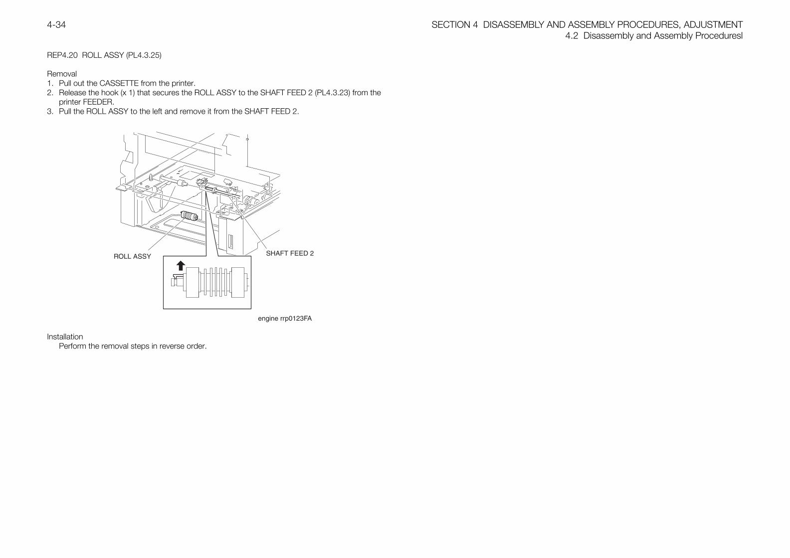
SECTION 4 DISASSEMBLY AND ASSEMBLY PROCEDURES, ADJUSTMENT4.2 Disassembly and Assembly Proceduresl
4-34
REP4.20 ROLL ASSY (PL4.3.25)
Removal1. Pull out the CASSETTE from the printer.2. Release the hook (x 1) that secures the ROLL ASSY to the SHAFT FEED 2 (PL4.3.23) from the
printer FEEDER.3. Pull the ROLL ASSY to the left and remove it from the SHAFT FEED 2.
InstallationPerform the removal steps in reverse order.
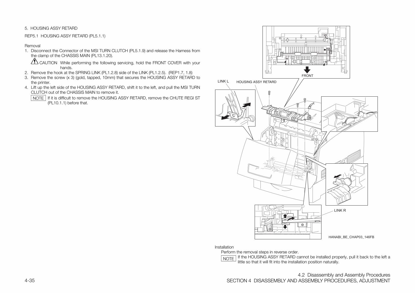
4.2 Disassembly and Assembly ProceduresSECTION 4 DISASSEMBLY AND ASSEMBLY PROCEDURES, ADJUSTMENT4-35
5. HOUSING ASSY RETARD
REP5.1 HOUSING ASSY RETARD (PL5.1.1)
Removal1. Disconnect the Connector of the MSI TURN CLUTCH (PL5.1.9) and release the Harness from
the clamp of the CHASSIS MAIN (PL13.1.20).
CAUTION While performing the following servicing, hold the FRONT COVER with yourhands.
2. Remove the hook at the SPRING LINK (PL1.2.8) side of the LINK (PL1.2.5). (REP1.7, 1.8)3. Remove the screw (x 3) (gold, tapped, 10mm) that secures the HOUSING ASSY RETARD to
the printer.4. Lift up the left side of the HOUSING ASSY RETARD, shift it to the left, and pull the MSI TURN
CLUTCH out of the CHASSIS MAIN to remove it.If it is difficult to remove the HOUSING ASSY RETARD, remove the CHUTE REGI ST(PL10.1.1) before that.
FRONT
HANABI_BE_CHAP03_146FB
LINK R
LINK L
InstallationPerform the removal steps in reverse order.
If the HOUSING ASSY RETARD cannot be installed properly, pull it back to the left alittle so that it will fit into the installation position naturally.
NOTE
NOTE
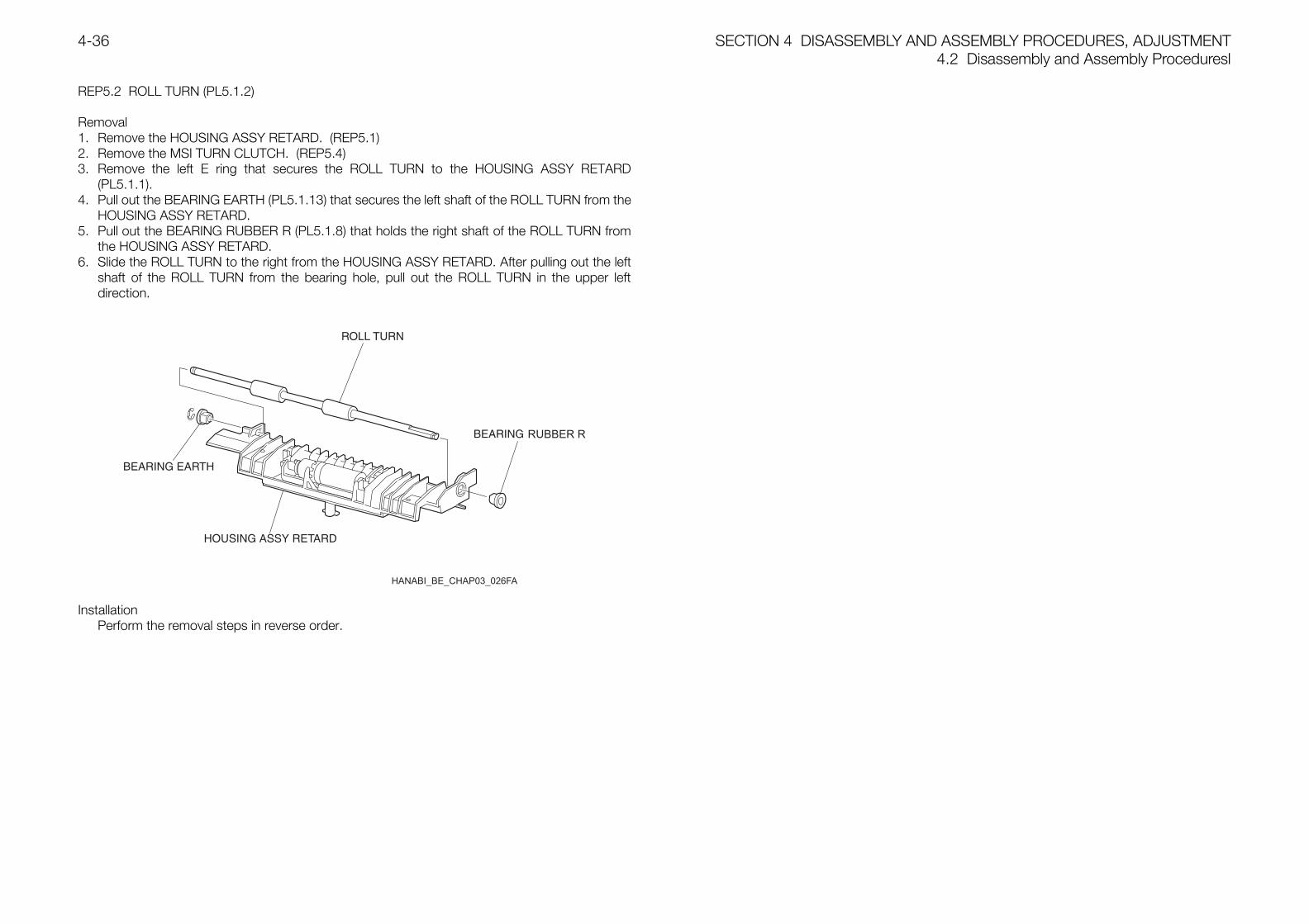
SECTION 4 DISASSEMBLY AND ASSEMBLY PROCEDURES, ADJUSTMENT4.2 Disassembly and Assembly Proceduresl
4-36
REP5.2 ROLL TURN (PL5.1.2)
Removal1. Remove the HOUSING ASSY RETARD. (REP5.1)2. Remove the MSI TURN CLUTCH. (REP5.4)3. Remove the left E ring that secures the ROLL TURN to the HOUSING ASSY RETARD
(PL5.1.1).4. Pull out the BEARING EARTH (PL5.1.13) that secures the left shaft of the ROLL TURN from the
HOUSING ASSY RETARD.5. Pull out the BEARING RUBBER R (PL5.1.8) that holds the right shaft of the ROLL TURN from
the HOUSING ASSY RETARD.6. Slide the ROLL TURN to the right from the HOUSING ASSY RETARD. After pulling out the left
shaft of the ROLL TURN from the bearing hole, pull out the ROLL TURN in the upper leftdirection.
InstallationPerform the removal steps in reverse order.
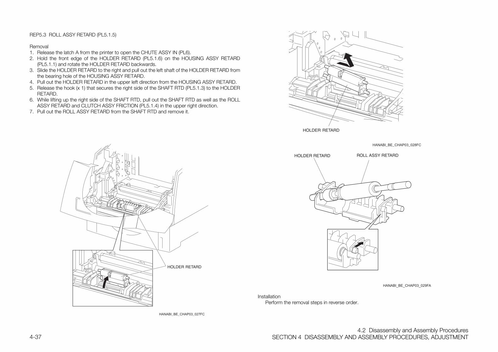
4.2 Disassembly and Assembly ProceduresSECTION 4 DISASSEMBLY AND ASSEMBLY PROCEDURES, ADJUSTMENT4-37
REP5.3 ROLL ASSY RETARD (PL5.1.5)
Removal1. Release the latch A from the printer to open the CHUTE ASSY IN (PL6).2. Hold the front edge of the HOLDER RETARD (PL5.1.6) on the HOUSING ASSY RETARD
(PL5.1.1) and rotate the HOLDER RETARD backwards.3. Slide the HOLDER RETARD to the right and pull out the left shaft of the HOLDER RETARD from
the bearing hole of the HOUSING ASSY RETARD.4. Pull out the HOLDER RETARD in the upper left direction from the HOUSING ASSY RETARD.5. Release the hook (x 1) that secures the right side of the SHAFT RTD (PL5.1.3) to the HOLDER
RETARD.6. While lifting up the right side of the SHAFT RTD, pull out the SHAFT RTD as well as the ROLL
ASSY RETARD and CLUTCH ASSY FRICTION (PL5.1.4) in the upper right direction.7. Pull out the ROLL ASSY RETARD from the SHAFT RTD and remove it.
HANABI_BE_CHAP03_027FC
HANABI_BE_CHAP03_028FC
InstallationPerform the removal steps in reverse order.
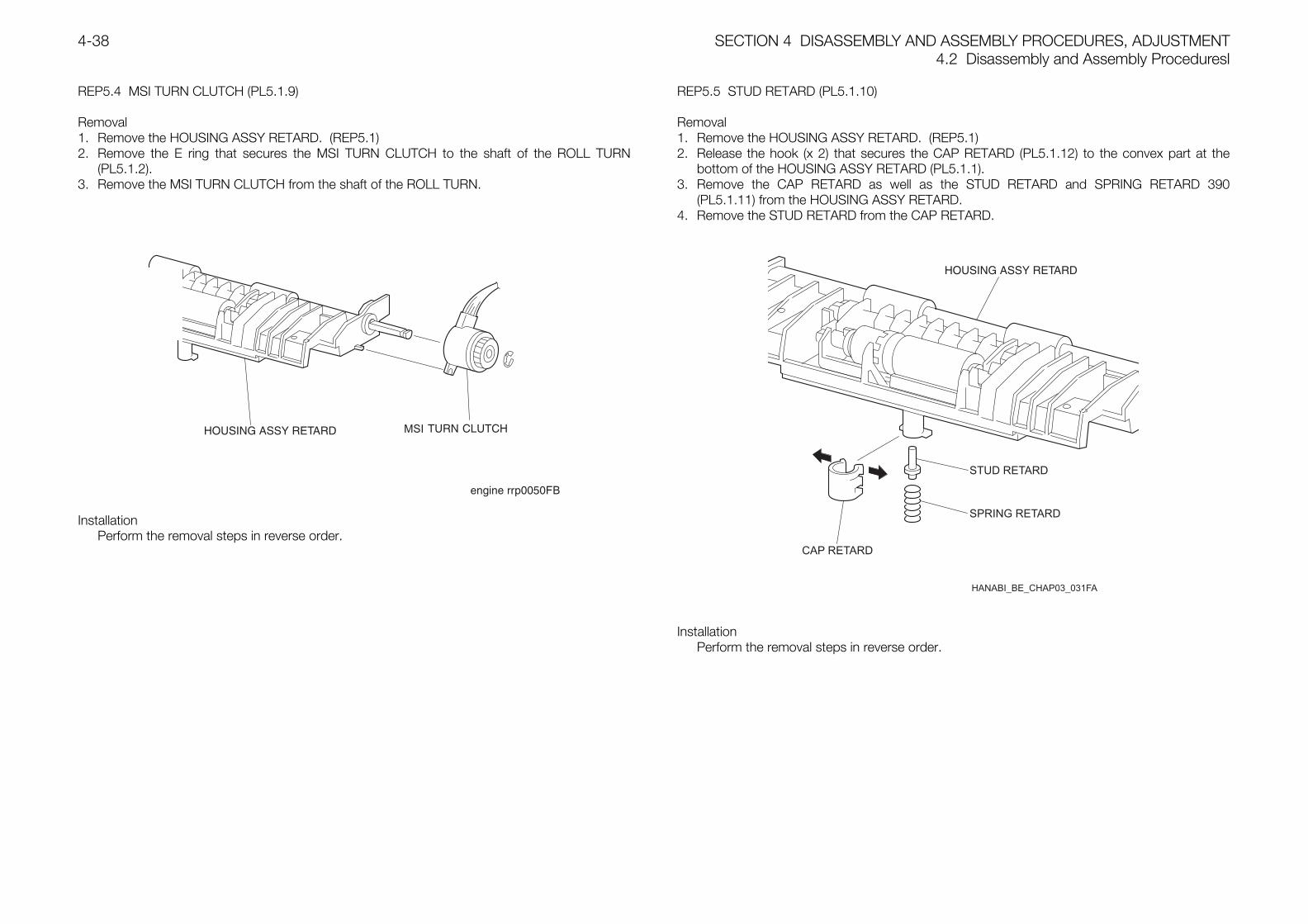
SECTION 4 DISASSEMBLY AND ASSEMBLY PROCEDURES, ADJUSTMENT4.2 Disassembly and Assembly Proceduresl
4-38
REP5.4 MSI TURN CLUTCH (PL5.1.9)
Removal1. Remove the HOUSING ASSY RETARD. (REP5.1)2. Remove the E ring that secures the MSI TURN CLUTCH to the shaft of the ROLL TURN
(PL5.1.2).3. Remove the MSI TURN CLUTCH from the shaft of the ROLL TURN.
InstallationPerform the removal steps in reverse order.
REP5.5 STUD RETARD (PL5.1.10)
Removal1. Remove the HOUSING ASSY RETARD. (REP5.1)2. Release the hook (x 2) that secures the CAP RETARD (PL5.1.12) to the convex part at the
bottom of the HOUSING ASSY RETARD (PL5.1.1).3. Remove the CAP RETARD as well as the STUD RETARD and SPRING RETARD 390
(PL5.1.11) from the HOUSING ASSY RETARD.4. Remove the STUD RETARD from the CAP RETARD.
InstallationPerform the removal steps in reverse order.
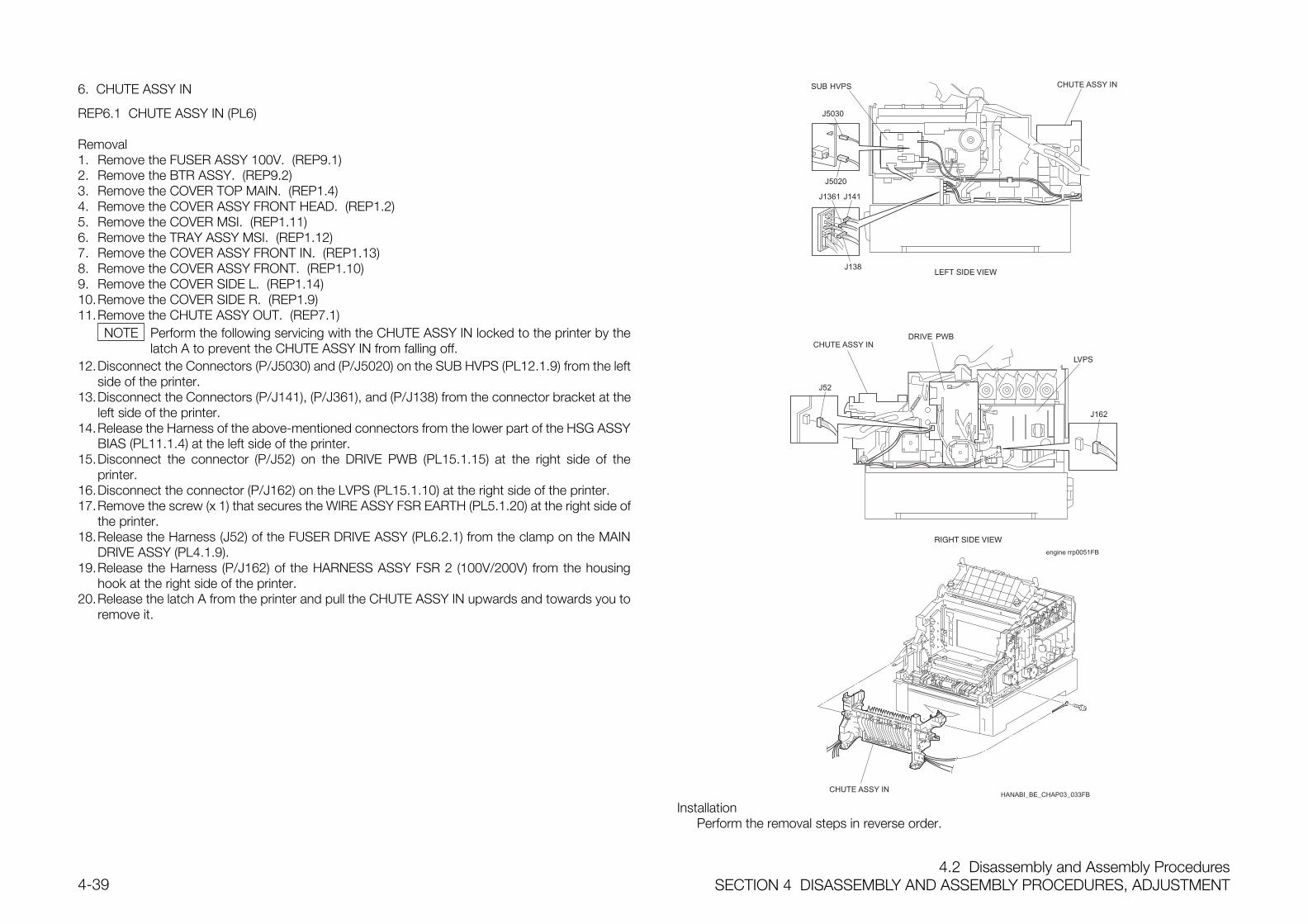
4.2 Disassembly and Assembly ProceduresSECTION 4 DISASSEMBLY AND ASSEMBLY PROCEDURES, ADJUSTMENT4-39
6. CHUTE ASSY IN
REP6.1 CHUTE ASSY IN (PL6)
Removal1. Remove the FUSER ASSY 100V. (REP9.1)2. Remove the BTR ASSY. (REP9.2)3. Remove the COVER TOP MAIN. (REP1.4)4. Remove the COVER ASSY FRONT HEAD. (REP1.2)5. Remove the COVER MSI. (REP1.11)6. Remove the TRAY ASSY MSI. (REP1.12)7. Remove the COVER ASSY FRONT IN. (REP1.13)8. Remove the COVER ASSY FRONT. (REP1.10)9. Remove the COVER SIDE L. (REP1.14)10.Remove the COVER SIDE R. (REP1.9)11.Remove the CHUTE ASSY OUT. (REP7.1)
Perform the following servicing with the CHUTE ASSY IN locked to the printer by thelatch A to prevent the CHUTE ASSY IN from falling off.
12.Disconnect the Connectors (P/J5030) and (P/J5020) on the SUB HVPS (PL12.1.9) from the leftside of the printer.
13.Disconnect the Connectors (P/J141), (P/J361), and (P/J138) from the connector bracket at theleft side of the printer.
14.Release the Harness of the above-mentioned connectors from the lower part of the HSG ASSYBIAS (PL11.1.4) at the left side of the printer.
15.Disconnect the connector (P/J52) on the DRIVE PWB (PL15.1.15) at the right side of theprinter.
16.Disconnect the connector (P/J162) on the LVPS (PL15.1.10) at the right side of the printer.17.Remove the screw (x 1) that secures the WIRE ASSY FSR EARTH (PL5.1.20) at the right side of
the printer.18.Release the Harness (J52) of the FUSER DRIVE ASSY (PL6.2.1) from the clamp on the MAIN
DRIVE ASSY (PL4.1.9).19.Release the Harness (P/J162) of the HARNESS ASSY FSR 2 (100V/200V) from the housing
hook at the right side of the printer.20.Release the latch A from the printer and pull the CHUTE ASSY IN upwards and towards you to
remove it.
engine rrp0051FB
J5030
J5020
J141J1361
J138
J52
J162
HANABI_BE_CHAP03_033FB
InstallationPerform the removal steps in reverse order.
NOTE
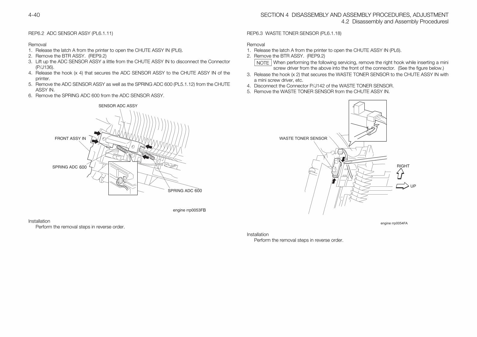
SECTION 4 DISASSEMBLY AND ASSEMBLY PROCEDURES, ADJUSTMENT4.2 Disassembly and Assembly Proceduresl
4-40
REP6.2 ADC SENSOR ASSY (PL6.1.11)
Removal1. Release the latch A from the printer to open the CHUTE ASSY IN (PL6).2. Remove the BTR ASSY. (REP9.2)3. Lift up the ADC SENSOR ASSY a little from the CHUTE ASSY IN to disconnect the Connector
(P/J136).4. Release the hook (x 4) that secures the ADC SENSOR ASSY to the CHUTE ASSY IN of the
printer.5. Remove the ADC SENSOR ASSY as well as the SPRING ADC 600 (PL5.1.12) from the CHUTE
ASSY IN.6. Remove the SPRING ADC 600 from the ADC SENSOR ASSY.
InstallationPerform the removal steps in reverse order.
REP6.3 WASTE TONER SENSOR (PL6.1.18)
Removal1. Release the latch A from the printer to open the CHUTE ASSY IN (PL6).2. Remove the BTR ASSY. (REP9.2)
When performing the following servicing, remove the right hook while inserting a miniscrew driver from the above into the front of the connector. (See the figure below.)
3. Release the hook (x 2) that secures the WASTE TONER SENSOR to the CHUTE ASSY IN witha mini screw driver, etc.
4. Disconnect the Connector P/J142 of the WASTE TONER SENSOR.5. Remove the WASTE TONER SENSOR from the CHUTE ASSY IN.
engine rrp0054FA
WASTE TONER SENSOR
InstallationPerform the removal steps in reverse order.
NOTE
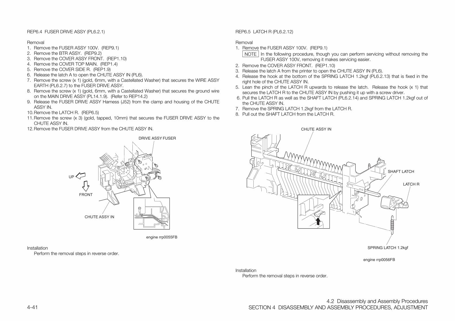
4.2 Disassembly and Assembly ProceduresSECTION 4 DISASSEMBLY AND ASSEMBLY PROCEDURES, ADJUSTMENT4-41
REP6.4 FUSER DRIVE ASSY (PL6.2.1)
Removal1. Remove the FUSER ASSY 100V. (REP9.1)2. Remove the BTR ASSY. (REP9.2)3. Remove the COVER ASSY FRONT. (REP1.10)4. Remove the COVER TOP MAIN. (REP1.4)5. Remove the COVER SIDE R. (REP1.9)6. Release the latch A to open the CHUTE ASSY IN (PL6).7. Remove the screw (x 1) (gold, 6mm, with a Castellated Washer) that secures the WIRE ASSY
EARTH (PL6.2.7) to the FUSER DRIVE ASSY.8. Remove the screw (x 1) (gold, 6mm, with a Castellated Washer) that secures the ground wire
on the MAIN DRIVE ASSY (PL14.1.9). (Refer to REP14.2)9. Release the FUSER DRIVE ASSY Harness (J52) from the clamp and housing of the CHUTE
ASSY IN.10.Remove the LATCH R. (REP6.5)11.Remove the screw (x 3) (gold, tapped, 10mm) that secures the FUSER DRIVE ASSY to the
CHUTE ASSY IN.12.Remove the FUSER DRIVE ASSY from the CHUTE ASSY IN.
engine rrp0055FB
InstallationPerform the removal steps in reverse order.
REP6.5 LATCH R (PL6.2.12)
Removal1. Remove the FUSER ASSY 100V. (REP9.1)
In the following procedure, though you can perform servicing without removing theFUSER ASSY 100V, removing it makes servicing easier.
2. Remove the COVER ASSY FRONT. (REP1.10)3. Release the latch A from the printer to open the CHUTE ASSY IN (PL6).4. Release the hook at the bottom of the SPRING LATCH 1.2kgf (PL6.2.13) that is fixed in the
right hole of the CHUTE ASSY IN.5. Lean the pinch of the LATCH R upwards to release the latch. Release the hook (x 1) that
secures the LATCH R to the CHUTE ASSY IN by pushing it up with a screw driver. 6. Pull the LATCH R as well as the SHAFT LATCH (PL6.2.14) and SPRING LATCH 1.2kgf out of
the CHUTE ASSY IN.7. Remove the SPRING LATCH 1.2kgf from the LATCH R.8. Pull out the SHAFT LATCH from the LATCH R.
InstallationPerform the removal steps in reverse order.
NOTE
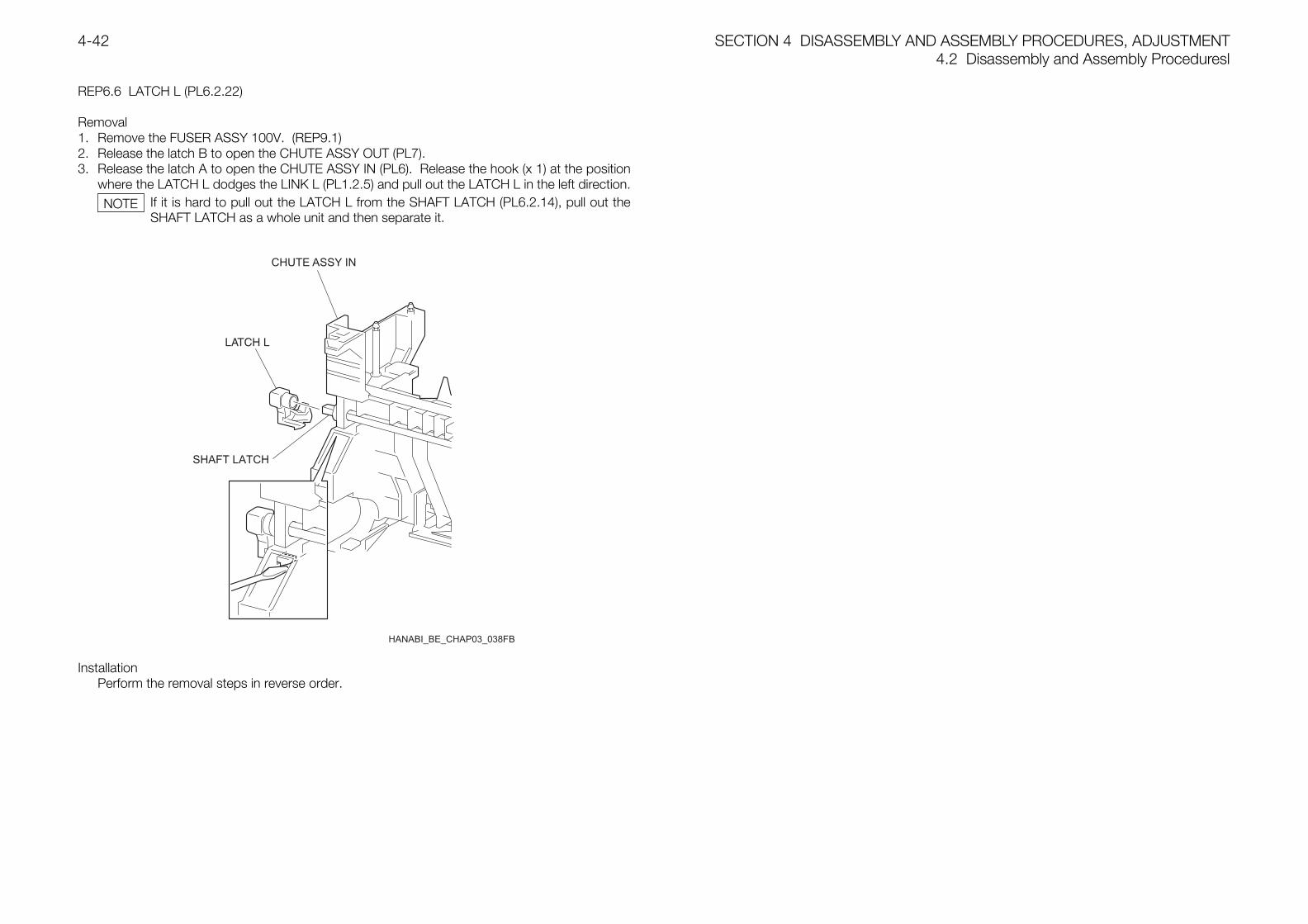
SECTION 4 DISASSEMBLY AND ASSEMBLY PROCEDURES, ADJUSTMENT4.2 Disassembly and Assembly Proceduresl
4-42
REP6.6 LATCH L (PL6.2.22)
Removal1. Remove the FUSER ASSY 100V. (REP9.1)2. Release the latch B to open the CHUTE ASSY OUT (PL7).3. Release the latch A to open the CHUTE ASSY IN (PL6). Release the hook (x 1) at the position
where the LATCH L dodges the LINK L (PL1.2.5) and pull out the LATCH L in the left direction.If it is hard to pull out the LATCH L from the SHAFT LATCH (PL6.2.14), pull out theSHAFT LATCH as a whole unit and then separate it.
InstallationPerform the removal steps in reverse order.
NOTE
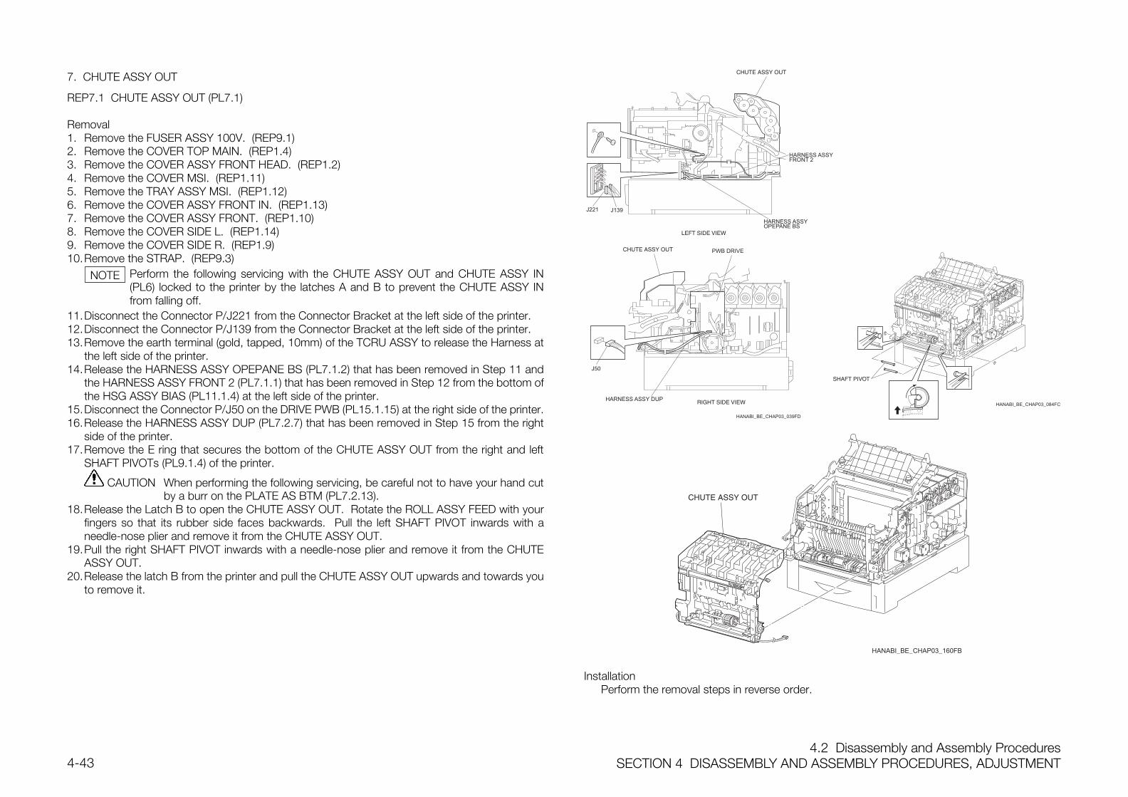
4.2 Disassembly and Assembly ProceduresSECTION 4 DISASSEMBLY AND ASSEMBLY PROCEDURES, ADJUSTMENT4-43
7. CHUTE ASSY OUT
REP7.1 CHUTE ASSY OUT (PL7.1)
Removal1. Remove the FUSER ASSY 100V. (REP9.1)2. Remove the COVER TOP MAIN. (REP1.4)3. Remove the COVER ASSY FRONT HEAD. (REP1.2)4. Remove the COVER MSI. (REP1.11)5. Remove the TRAY ASSY MSI. (REP1.12)6. Remove the COVER ASSY FRONT IN. (REP1.13)7. Remove the COVER ASSY FRONT. (REP1.10)8. Remove the COVER SIDE L. (REP1.14)9. Remove the COVER SIDE R. (REP1.9)10.Remove the STRAP. (REP9.3)
Perform the following servicing with the CHUTE ASSY OUT and CHUTE ASSY IN(PL6) locked to the printer by the latches A and B to prevent the CHUTE ASSY INfrom falling off.
11.Disconnect the Connector P/J221 from the Connector Bracket at the left side of the printer.12.Disconnect the Connector P/J139 from the Connector Bracket at the left side of the printer.13.Remove the earth terminal (gold, tapped, 10mm) of the TCRU ASSY to release the Harness at
the left side of the printer.14.Release the HARNESS ASSY OPEPANE BS (PL7.1.2) that has been removed in Step 11 and
the HARNESS ASSY FRONT 2 (PL7.1.1) that has been removed in Step 12 from the bottom ofthe HSG ASSY BIAS (PL11.1.4) at the left side of the printer.
15.Disconnect the Connector P/J50 on the DRIVE PWB (PL15.1.15) at the right side of the printer.16.Release the HARNESS ASSY DUP (PL7.2.7) that has been removed in Step 15 from the right
side of the printer.17.Remove the E ring that secures the bottom of the CHUTE ASSY OUT from the right and left
SHAFT PIVOTs (PL9.1.4) of the printer.
CAUTION When performing the following servicing, be careful not to have your hand cutby a burr on the PLATE AS BTM (PL7.2.13).
18.Release the Latch B to open the CHUTE ASSY OUT. Rotate the ROLL ASSY FEED with yourfingers so that its rubber side faces backwards. Pull the left SHAFT PIVOT inwards with aneedle-nose plier and remove it from the CHUTE ASSY OUT.
19.Pull the right SHAFT PIVOT inwards with a needle-nose plier and remove it from the CHUTEASSY OUT.
20.Release the latch B from the printer and pull the CHUTE ASSY OUT upwards and towards youto remove it.
HANABI_BE_CHAP03_039FD
J221 J139
J50
HANABI_BE_CHAP03_084FC
HANABI_BE_CHAP03_160FB
InstallationPerform the removal steps in reverse order.
NOTE
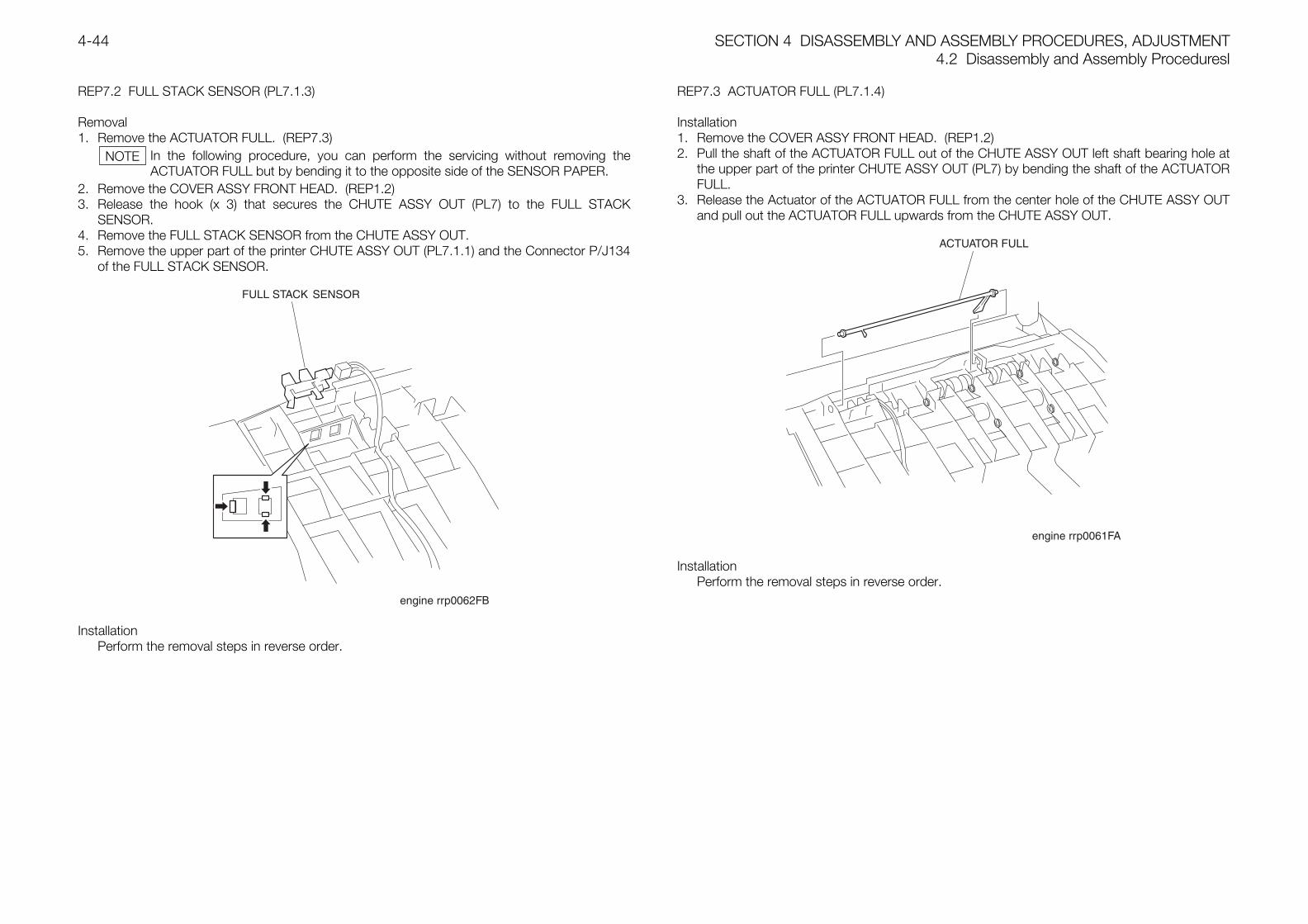
SECTION 4 DISASSEMBLY AND ASSEMBLY PROCEDURES, ADJUSTMENT4.2 Disassembly and Assembly Proceduresl
4-44
REP7.2 FULL STACK SENSOR (PL7.1.3)
Removal1. Remove the ACTUATOR FULL. (REP7.3)
In the following procedure, you can perform the servicing without removing theACTUATOR FULL but by bending it to the opposite side of the SENSOR PAPER.
2. Remove the COVER ASSY FRONT HEAD. (REP1.2)3. Release the hook (x 3) that secures the CHUTE ASSY OUT (PL7) to the FULL STACK
SENSOR.4. Remove the FULL STACK SENSOR from the CHUTE ASSY OUT.5. Remove the upper part of the printer CHUTE ASSY OUT (PL7.1.1) and the Connector P/J134
of the FULL STACK SENSOR.
InstallationPerform the removal steps in reverse order.
REP7.3 ACTUATOR FULL (PL7.1.4)
Installation1. Remove the COVER ASSY FRONT HEAD. (REP1.2)2. Pull the shaft of the ACTUATOR FULL out of the CHUTE ASSY OUT left shaft bearing hole at
the upper part of the printer CHUTE ASSY OUT (PL7) by bending the shaft of the ACTUATORFULL.
3. Release the Actuator of the ACTUATOR FULL from the center hole of the CHUTE ASSY OUTand pull out the ACTUATOR FULL upwards from the CHUTE ASSY OUT.
InstallationPerform the removal steps in reverse order.
NOTE
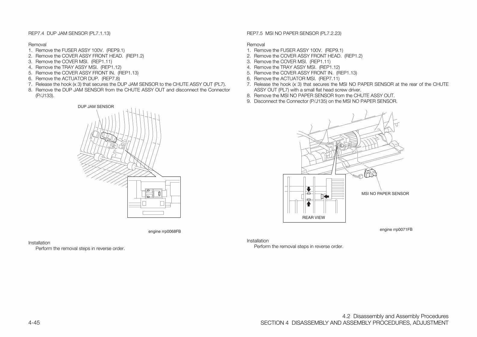
4.2 Disassembly and Assembly ProceduresSECTION 4 DISASSEMBLY AND ASSEMBLY PROCEDURES, ADJUSTMENT4-45
REP7.4 DUP JAM SENSOR (PL7.1.13)
Removal1. Remove the FUSER ASSY 100V. (REP9.1)2. Remove the COVER ASSY FRONT HEAD. (REP1.2)3. Remove the COVER MSI. (REP1.11)4. Remove the TRAY ASSY MSI. (REP1.12)5. Remove the COVER ASSY FRONT IN. (REP1.13)6. Remove the ACTUATOR DUP. (REP7.8)7. Release the hook (x 3) that secures the DUP JAM SENSOR to the CHUTE ASSY OUT (PL7).8. Remove the DUP JAM SENSOR from the CHUTE ASSY OUT and disconnect the Connector
(P/J133).
DUP JAM SENSOR
B
InstallationPerform the removal steps in reverse order.
REP7.5 MSI NO PAPER SENSOR (PL7.2.23)
Removal1. Remove the FUSER ASSY 100V. (REP9.1)2. Remove the COVER ASSY FRONT HEAD. (REP1.2)3. Remove the COVER MSI. (REP1.11)4. Remove the TRAY ASSY MSI. (REP1.12)5. Remove the COVER ASSY FRONT IN. (REP1.13)6. Remove the ACTUATOR MSI. (REP7.11)7. Release the hook (x 3) that secures the MSI NO PAPER SENSOR at the rear of the CHUTE
ASSY OUT (PL7) with a small flat head screw driver.8. Remove the MSI NO PAPER SENSOR from the CHUTE ASSY OUT.9. Disconnect the Connector (P/J135) on the MSI NO PAPER SENSOR.
MSI NO PAPER SENSOR
B
InstallationPerform the removal steps in reverse order.
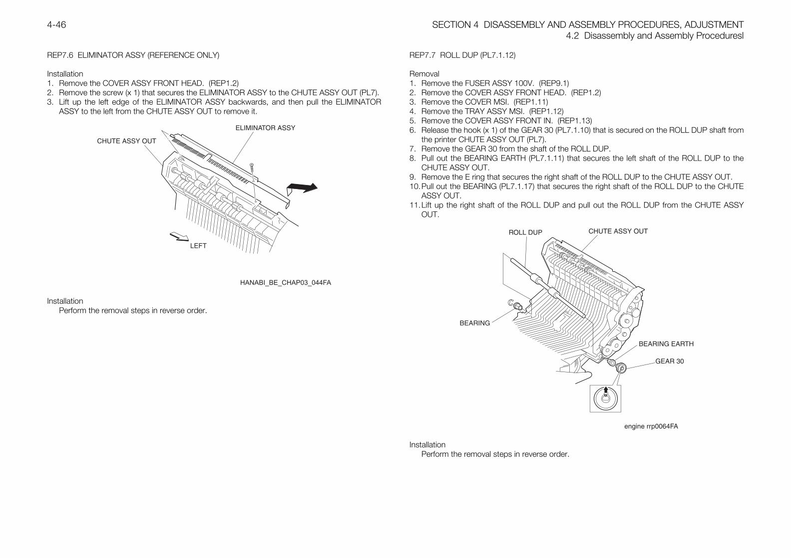
SECTION 4 DISASSEMBLY AND ASSEMBLY PROCEDURES, ADJUSTMENT4.2 Disassembly and Assembly Proceduresl
4-46
REP7.6 ELIMINATOR ASSY (REFERENCE ONLY)
Installation1. Remove the COVER ASSY FRONT HEAD. (REP1.2)2. Remove the screw (x 1) that secures the ELIMINATOR ASSY to the CHUTE ASSY OUT (PL7).3. Lift up the left edge of the ELIMINATOR ASSY backwards, and then pull the ELIMINATOR
ASSY to the left from the CHUTE ASSY OUT to remove it.
InstallationPerform the removal steps in reverse order.
REP7.7 ROLL DUP (PL7.1.12)
Removal1. Remove the FUSER ASSY 100V. (REP9.1)2. Remove the COVER ASSY FRONT HEAD. (REP1.2)3. Remove the COVER MSI. (REP1.11)4. Remove the TRAY ASSY MSI. (REP1.12)5. Remove the COVER ASSY FRONT IN. (REP1.13)6. Release the hook (x 1) of the GEAR 30 (PL7.1.10) that is secured on the ROLL DUP shaft from
the printer CHUTE ASSY OUT (PL7).7. Remove the GEAR 30 from the shaft of the ROLL DUP.8. Pull out the BEARING EARTH (PL7.1.11) that secures the left shaft of the ROLL DUP to the
CHUTE ASSY OUT.9. Remove the E ring that secures the right shaft of the ROLL DUP to the CHUTE ASSY OUT.10.Pull out the BEARING (PL7.1.17) that secures the right shaft of the ROLL DUP to the CHUTE
ASSY OUT.11.Lift up the right shaft of the ROLL DUP and pull out the ROLL DUP from the CHUTE ASSY
OUT.
InstallationPerform the removal steps in reverse order.
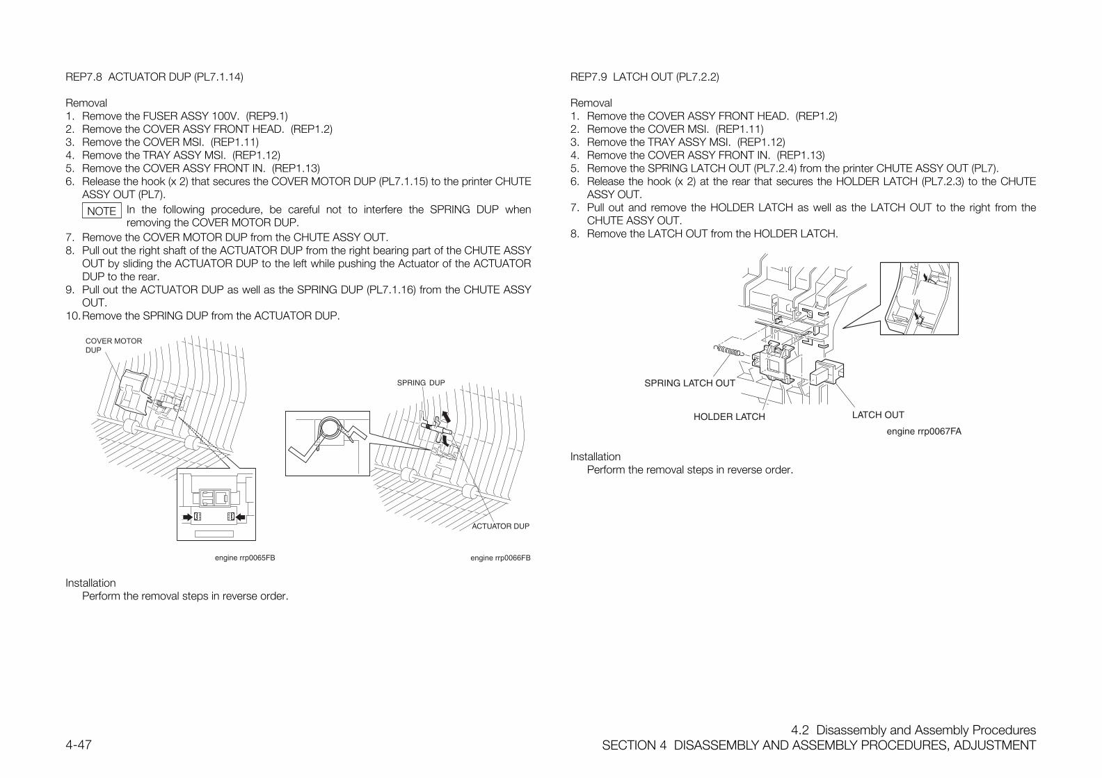
4.2 Disassembly and Assembly ProceduresSECTION 4 DISASSEMBLY AND ASSEMBLY PROCEDURES, ADJUSTMENT4-47
REP7.8 ACTUATOR DUP (PL7.1.14)
Removal1. Remove the FUSER ASSY 100V. (REP9.1)2. Remove the COVER ASSY FRONT HEAD. (REP1.2)3. Remove the COVER MSI. (REP1.11)4. Remove the TRAY ASSY MSI. (REP1.12)5. Remove the COVER ASSY FRONT IN. (REP1.13)6. Release the hook (x 2) that secures the COVER MOTOR DUP (PL7.1.15) to the printer CHUTE
ASSY OUT (PL7).In the following procedure, be careful not to interfere the SPRING DUP whenremoving the COVER MOTOR DUP.
7. Remove the COVER MOTOR DUP from the CHUTE ASSY OUT.8. Pull out the right shaft of the ACTUATOR DUP from the right bearing part of the CHUTE ASSY
OUT by sliding the ACTUATOR DUP to the left while pushing the Actuator of the ACTUATORDUP to the rear.
9. Pull out the ACTUATOR DUP as well as the SPRING DUP (PL7.1.16) from the CHUTE ASSYOUT.
10.Remove the SPRING DUP from the ACTUATOR DUP.
COVER MOTORDUP
B engine rrp0066FB
InstallationPerform the removal steps in reverse order.
REP7.9 LATCH OUT (PL7.2.2)
Removal1. Remove the COVER ASSY FRONT HEAD. (REP1.2)2. Remove the COVER MSI. (REP1.11)3. Remove the TRAY ASSY MSI. (REP1.12)4. Remove the COVER ASSY FRONT IN. (REP1.13)5. Remove the SPRING LATCH OUT (PL7.2.4) from the printer CHUTE ASSY OUT (PL7).6. Release the hook (x 2) at the rear that secures the HOLDER LATCH (PL7.2.3) to the CHUTE
ASSY OUT.7. Pull out and remove the HOLDER LATCH as well as the LATCH OUT to the right from the
CHUTE ASSY OUT.8. Remove the LATCH OUT from the HOLDER LATCH.
InstallationPerform the removal steps in reverse order.
NOTE
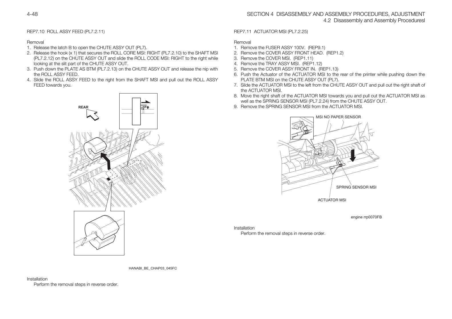
SECTION 4 DISASSEMBLY AND ASSEMBLY PROCEDURES, ADJUSTMENT4.2 Disassembly and Assembly Proceduresl
4-48
REP7.10 ROLL ASSY FEED (PL7.2.11)
Removal1. Release the latch B to open the CHUTE ASSY OUT (PL7).2. Release the hook (x 1) that secures the ROLL CORE MSI: RIGHT (PL7.2.10) to the SHAFT MSI
(PL7.2.12) on the CHUTE ASSY OUT and slide the ROLL CODE MSI: RIGHT to the right whilelooking at the slit part of the CHUTE ASSY OUT.
3. Push down the PLATE AS BTM (PL7.2.13) on the CHUTE ASSY OUT and release the nip withthe ROLL ASSY FEED.
4. Slide the ROLL ASSY FEED to the right from the SHAFT MSI and pull out the ROLL ASSYFEED towards you.
HANABI_BE_CHAP03_045FC
REAR
InstallationPerform the removal steps in reverse order.
REP7.11 ACTUATOR MSI (PL7.2.25)
Removal1. Remove the FUSER ASSY 100V. (REP9.1)2. Remove the COVER ASSY FRONT HEAD. (REP1.2)3. Remove the COVER MSI. (REP1.11)4. Remove the TRAY ASSY MSI. (REP1.12)5. Remove the COVER ASSY FRONT IN. (REP1.13)6. Push the Actuator of the ACTUATOR MSI to the rear of the printer while pushing down the
PLATE BTM MSI on the CHUTE ASSY OUT (PL7).7. Slide the ACTUATOR MSI to the left from the CHUTE ASSY OUT and pull out the right shaft of
the ACTUATOR MSI.8. Move the right shaft of the ACTUATOR MSI towards you and pull out the ACTUATOR MSI as
well as the SPRING SENSOR MSI (PL7.2.24) from the CHUTE ASSY OUT.9. Remove the SPRING SENSOR MSI from the ACTUATOR MSI.
engine rrp0070FB
MSI NO PAPER SENSOR
InstallationPerform the removal steps in reverse order.
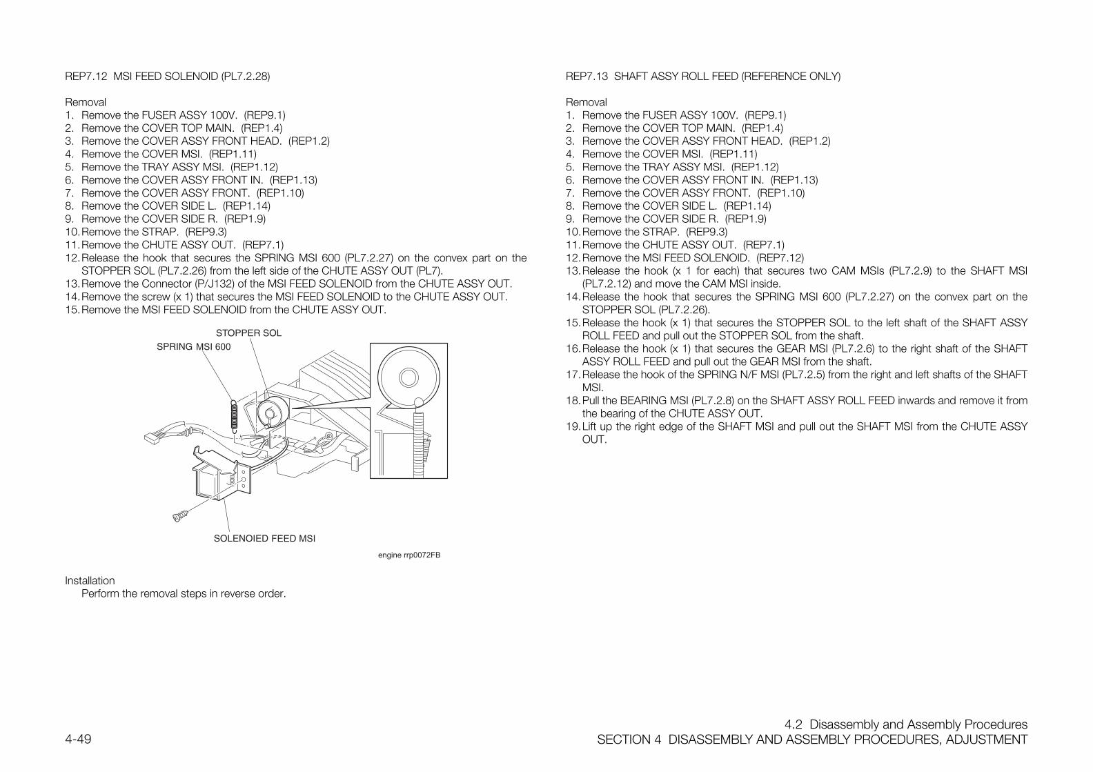
4.2 Disassembly and Assembly ProceduresSECTION 4 DISASSEMBLY AND ASSEMBLY PROCEDURES, ADJUSTMENT4-49
REP7.12 MSI FEED SOLENOID (PL7.2.28)
Removal1. Remove the FUSER ASSY 100V. (REP9.1)2. Remove the COVER TOP MAIN. (REP1.4)3. Remove the COVER ASSY FRONT HEAD. (REP1.2)4. Remove the COVER MSI. (REP1.11)5. Remove the TRAY ASSY MSI. (REP1.12)6. Remove the COVER ASSY FRONT IN. (REP1.13)7. Remove the COVER ASSY FRONT. (REP1.10)8. Remove the COVER SIDE L. (REP1.14)9. Remove the COVER SIDE R. (REP1.9)10.Remove the STRAP. (REP9.3)11.Remove the CHUTE ASSY OUT. (REP7.1)12.Release the hook that secures the SPRING MSI 600 (PL7.2.27) on the convex part on the
STOPPER SOL (PL7.2.26) from the left side of the CHUTE ASSY OUT (PL7).13.Remove the Connector (P/J132) of the MSI FEED SOLENOID from the CHUTE ASSY OUT.14.Remove the screw (x 1) that secures the MSI FEED SOLENOID to the CHUTE ASSY OUT.15.Remove the MSI FEED SOLENOID from the CHUTE ASSY OUT.
MSI 600
engine rrp0072FB
InstallationPerform the removal steps in reverse order.
REP7.13 SHAFT ASSY ROLL FEED (REFERENCE ONLY)
Removal1. Remove the FUSER ASSY 100V. (REP9.1)2. Remove the COVER TOP MAIN. (REP1.4)3. Remove the COVER ASSY FRONT HEAD. (REP1.2)4. Remove the COVER MSI. (REP1.11)5. Remove the TRAY ASSY MSI. (REP1.12)6. Remove the COVER ASSY FRONT IN. (REP1.13)7. Remove the COVER ASSY FRONT. (REP1.10)8. Remove the COVER SIDE L. (REP1.14)9. Remove the COVER SIDE R. (REP1.9)10.Remove the STRAP. (REP9.3)11.Remove the CHUTE ASSY OUT. (REP7.1)12.Remove the MSI FEED SOLENOID. (REP7.12)13.Release the hook (x 1 for each) that secures two CAM MSIs (PL7.2.9) to the SHAFT MSI
(PL7.2.12) and move the CAM MSI inside.14.Release the hook that secures the SPRING MSI 600 (PL7.2.27) on the convex part on the
STOPPER SOL (PL7.2.26).15.Release the hook (x 1) that secures the STOPPER SOL to the left shaft of the SHAFT ASSY
ROLL FEED and pull out the STOPPER SOL from the shaft.16.Release the hook (x 1) that secures the GEAR MSI (PL7.2.6) to the right shaft of the SHAFT
ASSY ROLL FEED and pull out the GEAR MSI from the shaft.17.Release the hook of the SPRING N/F MSI (PL7.2.5) from the right and left shafts of the SHAFT
MSI.18.Pull the BEARING MSI (PL7.2.8) on the SHAFT ASSY ROLL FEED inwards and remove it from
the bearing of the CHUTE ASSY OUT.19.Lift up the right edge of the SHAFT MSI and pull out the SHAFT MSI from the CHUTE ASSY
OUT.
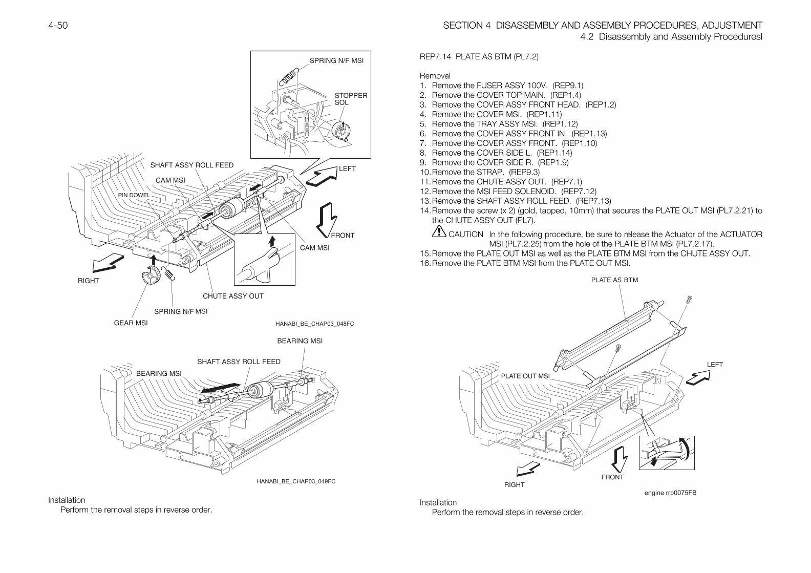
SECTION 4 DISASSEMBLY AND ASSEMBLY PROCEDURES, ADJUSTMENT4.2 Disassembly and Assembly Proceduresl
4-50
HANABI_BE_CHAP03_048FC
HANABI_BE_CHAP03_049FC
InstallationPerform the removal steps in reverse order.
REP7.14 PLATE AS BTM (PL7.2)
Removal1. Remove the FUSER ASSY 100V. (REP9.1)2. Remove the COVER TOP MAIN. (REP1.4)3. Remove the COVER ASSY FRONT HEAD. (REP1.2)4. Remove the COVER MSI. (REP1.11)5. Remove the TRAY ASSY MSI. (REP1.12)6. Remove the COVER ASSY FRONT IN. (REP1.13)7. Remove the COVER ASSY FRONT. (REP1.10)8. Remove the COVER SIDE L. (REP1.14)9. Remove the COVER SIDE R. (REP1.9)10.Remove the STRAP. (REP9.3)11.Remove the CHUTE ASSY OUT. (REP7.1)12.Remove the MSI FEED SOLENOID. (REP7.12)13.Remove the SHAFT ASSY ROLL FEED. (REP7.13)14.Remove the screw (x 2) (gold, tapped, 10mm) that secures the PLATE OUT MSI (PL7.2.21) to
the CHUTE ASSY OUT (PL7).
CAUTION In the following procedure, be sure to release the Actuator of the ACTUATORMSI (PL7.2.25) from the hole of the PLATE BTM MSI (PL7.2.17).
15.Remove the PLATE OUT MSI as well as the PLATE BTM MSI from the CHUTE ASSY OUT.16.Remove the PLATE BTM MSI from the PLATE OUT MSI.
engine rrp0075FB
InstallationPerform the removal steps in reverse order.
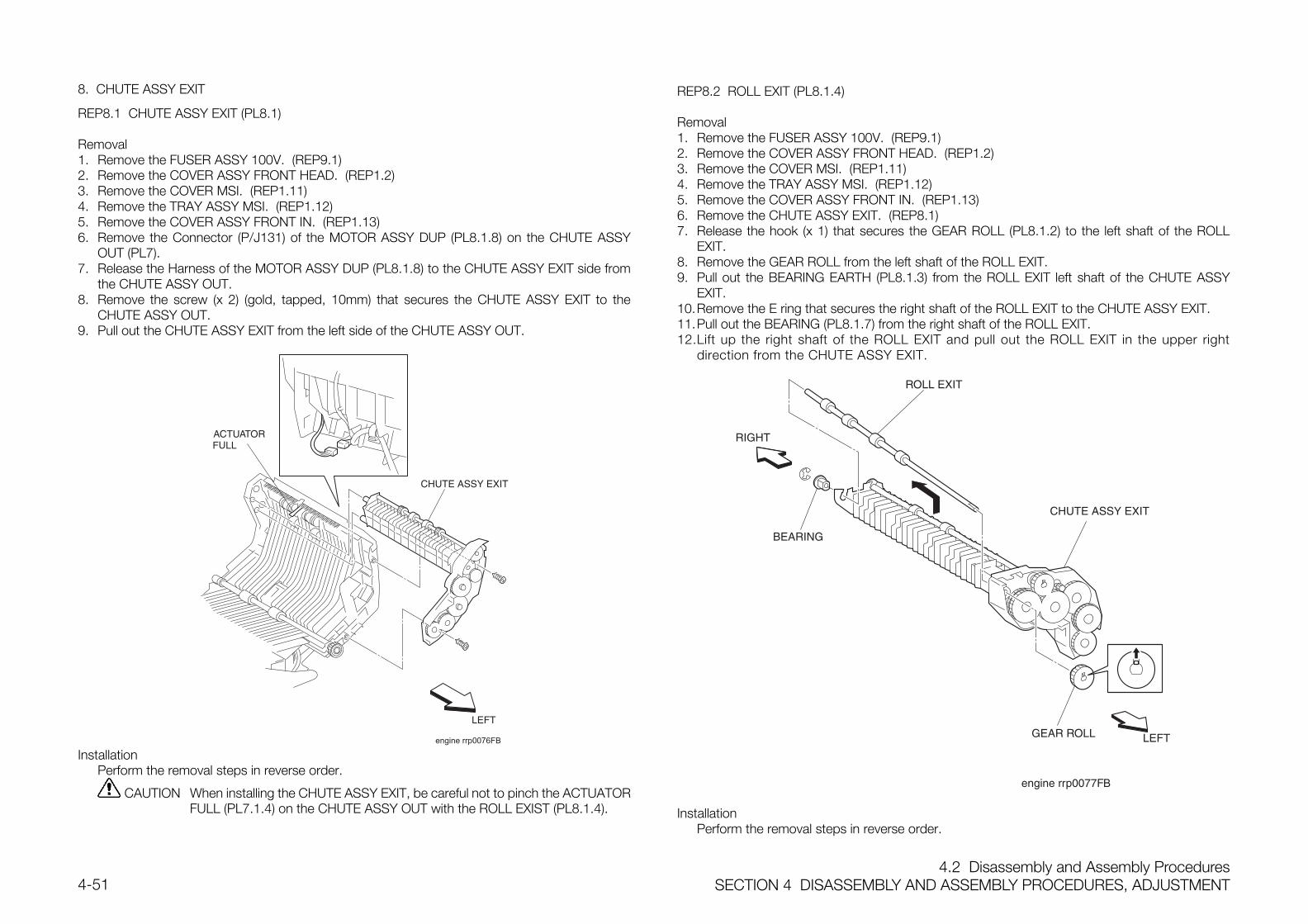
4.2 Disassembly and Assembly ProceduresSECTION 4 DISASSEMBLY AND ASSEMBLY PROCEDURES, ADJUSTMENT4-51
8. CHUTE ASSY EXIT
REP8.1 CHUTE ASSY EXIT (PL8.1)
Removal1. Remove the FUSER ASSY 100V. (REP9.1)2. Remove the COVER ASSY FRONT HEAD. (REP1.2)3. Remove the COVER MSI. (REP1.11)4. Remove the TRAY ASSY MSI. (REP1.12)5. Remove the COVER ASSY FRONT IN. (REP1.13)6. Remove the Connector (P/J131) of the MOTOR ASSY DUP (PL8.1.8) on the CHUTE ASSY
OUT (PL7).7. Release the Harness of the MOTOR ASSY DUP (PL8.1.8) to the CHUTE ASSY EXIT side from
the CHUTE ASSY OUT.8. Remove the screw (x 2) (gold, tapped, 10mm) that secures the CHUTE ASSY EXIT to the
CHUTE ASSY OUT.9. Pull out the CHUTE ASSY EXIT from the left side of the CHUTE ASSY OUT.
engine rrp0076FB
InstallationPerform the removal steps in reverse order.
CAUTION When installing the CHUTE ASSY EXIT, be careful not to pinch the ACTUATORFULL (PL7.1.4) on the CHUTE ASSY OUT with the ROLL EXIST (PL8.1.4).
REP8.2 ROLL EXIT (PL8.1.4)
Removal1. Remove the FUSER ASSY 100V. (REP9.1)2. Remove the COVER ASSY FRONT HEAD. (REP1.2)3. Remove the COVER MSI. (REP1.11)4. Remove the TRAY ASSY MSI. (REP1.12)5. Remove the COVER ASSY FRONT IN. (REP1.13)6. Remove the CHUTE ASSY EXIT. (REP8.1)7. Release the hook (x 1) that secures the GEAR ROLL (PL8.1.2) to the left shaft of the ROLL
EXIT.8. Remove the GEAR ROLL from the left shaft of the ROLL EXIT.9. Pull out the BEARING EARTH (PL8.1.3) from the ROLL EXIT left shaft of the CHUTE ASSY
EXIT.10.Remove the E ring that secures the right shaft of the ROLL EXIT to the CHUTE ASSY EXIT.11.Pull out the BEARING (PL8.1.7) from the right shaft of the ROLL EXIT.12.Lift up the right shaft of the ROLL EXIT and pull out the ROLL EXIT in the upper right
direction from the CHUTE ASSY EXIT.
InstallationPerform the removal steps in reverse order.
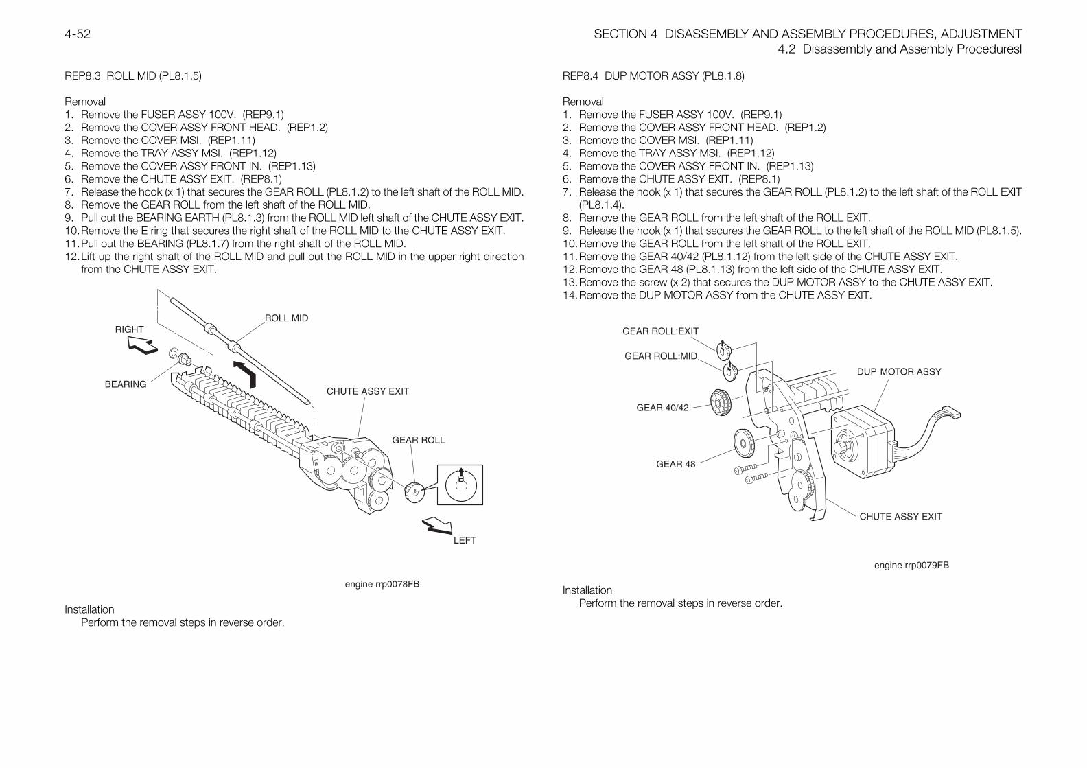
SECTION 4 DISASSEMBLY AND ASSEMBLY PROCEDURES, ADJUSTMENT4.2 Disassembly and Assembly Proceduresl
4-52
REP8.3 ROLL MID (PL8.1.5)
Removal1. Remove the FUSER ASSY 100V. (REP9.1)2. Remove the COVER ASSY FRONT HEAD. (REP1.2)3. Remove the COVER MSI. (REP1.11)4. Remove the TRAY ASSY MSI. (REP1.12)5. Remove the COVER ASSY FRONT IN. (REP1.13)6. Remove the CHUTE ASSY EXIT. (REP8.1)7. Release the hook (x 1) that secures the GEAR ROLL (PL8.1.2) to the left shaft of the ROLL MID.8. Remove the GEAR ROLL from the left shaft of the ROLL MID.9. Pull out the BEARING EARTH (PL8.1.3) from the ROLL MID left shaft of the CHUTE ASSY EXIT.10.Remove the E ring that secures the right shaft of the ROLL MID to the CHUTE ASSY EXIT.11.Pull out the BEARING (PL8.1.7) from the right shaft of the ROLL MID.12.Lift up the right shaft of the ROLL MID and pull out the ROLL MID in the upper right direction
from the CHUTE ASSY EXIT.
InstallationPerform the removal steps in reverse order.
REP8.4 DUP MOTOR ASSY (PL8.1.8)
Removal1. Remove the FUSER ASSY 100V. (REP9.1)2. Remove the COVER ASSY FRONT HEAD. (REP1.2)3. Remove the COVER MSI. (REP1.11)4. Remove the TRAY ASSY MSI. (REP1.12)5. Remove the COVER ASSY FRONT IN. (REP1.13)6. Remove the CHUTE ASSY EXIT. (REP8.1)7. Release the hook (x 1) that secures the GEAR ROLL (PL8.1.2) to the left shaft of the ROLL EXIT
(PL8.1.4).8. Remove the GEAR ROLL from the left shaft of the ROLL EXIT.9. Release the hook (x 1) that secures the GEAR ROLL to the left shaft of the ROLL MID (PL8.1.5).10.Remove the GEAR ROLL from the left shaft of the ROLL EXIT.11.Remove the GEAR 40/42 (PL8.1.12) from the left side of the CHUTE ASSY EXIT.12.Remove the GEAR 48 (PL8.1.13) from the left side of the CHUTE ASSY EXIT.13.Remove the screw (x 2) that secures the DUP MOTOR ASSY to the CHUTE ASSY EXIT.14.Remove the DUP MOTOR ASSY from the CHUTE ASSY EXIT.
InstallationPerform the removal steps in reverse order.
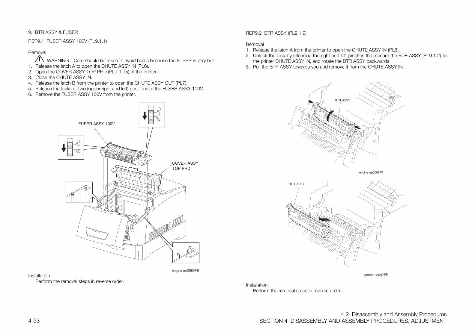
4.2 Disassembly and Assembly ProceduresSECTION 4 DISASSEMBLY AND ASSEMBLY PROCEDURES, ADJUSTMENT4-53
9. BTR ASSY & FUSER
REP9.1 FUSER ASSY 100V (PL9.1.1)
Removal
WARNING Care should be taken to avoid burns because the FUSER is very hot.1. Release the latch A to open the CHUTE ASSY IN (PL6).2. Open the COVER ASSY TOP PHD (PL1.1.15) of the printer.3. Close the CHUTE ASSY IN.4. Release the latch B from the printer to open the CHUTE ASSY OUT (PL7).5. Release the locks at two (upper right and left) positions of the FUSER ASSY 100V.6. Remove the FUSER ASSY 100V from the printer.
InstallationPerform the removal steps in reverse order.
REP9.2 BTR ASSY (PL9.1.2)
Removal1. Release the latch A from the printer to open the CHUTE ASSY IN (PL6).2. Unlock the lock by releasing the right and left pinches that secure the BTR ASSY (PL9.1.2) to
the printer CHUTE ASSY IN, and rotate the BTR ASSY backwards.3. Pull the BTR ASSY towards you and remove it from the CHUTE ASSY IN.
InstallationPerform the removal steps in reverse order.
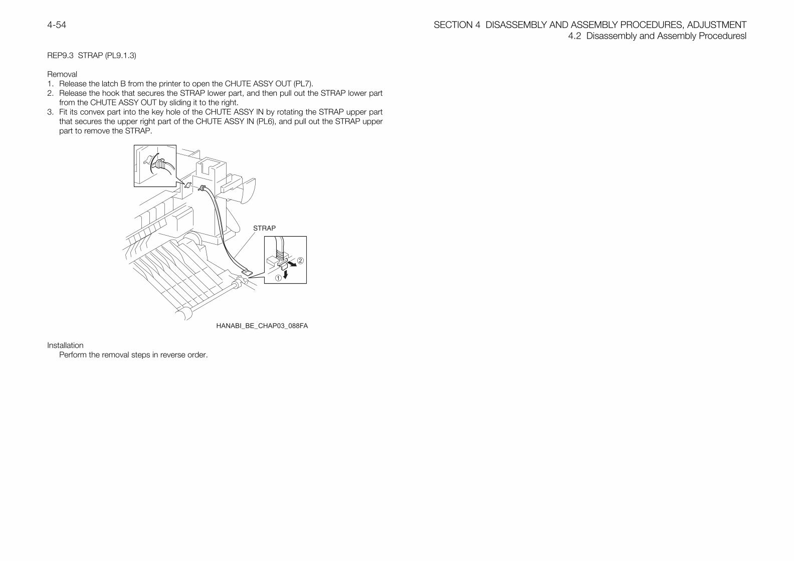
SECTION 4 DISASSEMBLY AND ASSEMBLY PROCEDURES, ADJUSTMENT4.2 Disassembly and Assembly Proceduresl
4-54
REP9.3 STRAP (PL9.1.3)
Removal1. Release the latch B from the printer to open the CHUTE ASSY OUT (PL7).2. Release the hook that secures the STRAP lower part, and then pull out the STRAP lower part
from the CHUTE ASSY OUT by sliding it to the right.3. Fit its convex part into the key hole of the CHUTE ASSY IN by rotating the STRAP upper part
that secures the upper right part of the CHUTE ASSY IN (PL6), and pull out the STRAP upperpart to remove the STRAP.
2
1
HANABI_BE_CHAP03_088FA
InstallationPerform the removal steps in reverse order.
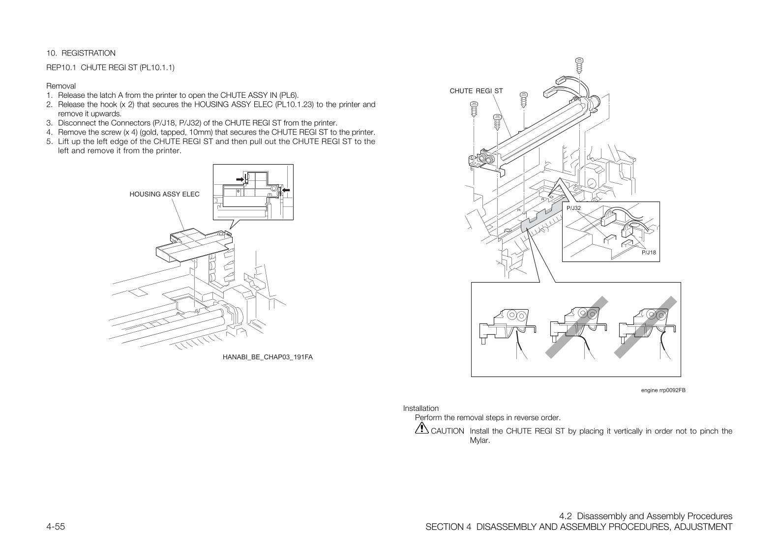
4.2 Disassembly and Assembly ProceduresSECTION 4 DISASSEMBLY AND ASSEMBLY PROCEDURES, ADJUSTMENT4-55
10. REGISTRATION
REP10.1 CHUTE REGI ST (PL10.1.1)
Removal1. Release the latch A from the printer to open the CHUTE ASSY IN (PL6).2. Release the hook (x 2) that secures the HOUSING ASSY ELEC (PL10.1.23) to the printer and
remove it upwards.3. Disconnect the Connectors (P/J18, P/J32) of the CHUTE REGI ST from the printer.4. Remove the screw (x 4) (gold, tapped, 10mm) that secures the CHUTE REGI ST to the printer.5. Lift up the left edge of the CHUTE REGI ST and then pull out the CHUTE REGI ST to the
left and remove it from the printer.
HANABI_BE_CHAP03_191FA
P/J18
P/J32
engine rrp0092FB
InstallationPerform the removal steps in reverse order.
CAUTION Install the CHUTE REGI ST by placing it vertically in order not to pinch theMylar.
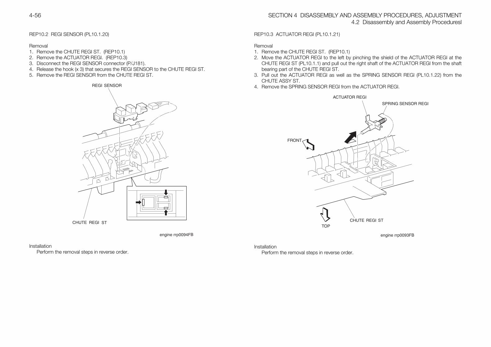
SECTION 4 DISASSEMBLY AND ASSEMBLY PROCEDURES, ADJUSTMENT4.2 Disassembly and Assembly Proceduresl
4-56
REP10.2 REGI SENSOR (PL10.1.20)
Removal1. Remove the CHUTE REGI ST. (REP10.1)2. Remove the ACTUATOR REGI. (REP10.3)3. Disconnect the REGI SENSOR connector (P/J181).4. Release the hook (x 3) that secures the REGI SENSOR to the CHUTE REGI ST.5. Remove the REGI SENSOR from the CHUTE REGI ST.
InstallationPerform the removal steps in reverse order.
REP10.3 ACTUATOR REGI (PL10.1.21)
Removal1. Remove the CHUTE REGI ST. (REP10.1)2. Move the ACTUATOR REGI to the left by pinching the shield of the ACTUATOR REGI at the
CHUTE REGI ST (PL10.1.1) and pull out the right shaft of the ACTUATOR REGI from the shaftbearing part of the CHUTE REGI ST.
3. Pull out the ACTUATOR REGI as well as the SPRING SENSOR REGI (PL10.1.22) from theCHUTE ASSY ST.
4. Remove the SPRING SENSOR REGI from the ACTUATOR REGI.
InstallationPerform the removal steps in reverse order.
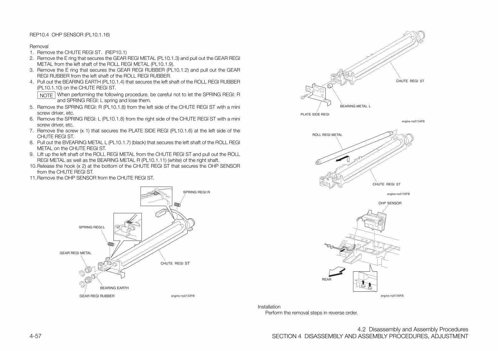
4.2 Disassembly and Assembly ProceduresSECTION 4 DISASSEMBLY AND ASSEMBLY PROCEDURES, ADJUSTMENT4-57
REP10.4 OHP SENSOR (PL10.1.16)
Removal1. Remove the CHUTE REGI ST. (REP10.1)2. Remove the E ring that secures the GEAR REGI METAL (PL10.1.3) and pull out the GEAR REGI
METAL from the left shaft of the ROLL REGI METAL (PL10.1.9).3. Remove the E ring that secures the GEAR REGI RUBBER (PL10.1.2) and pull out the GEAR
REGI RUBBER from the left shaft of the ROLL REGI RUBBER.4. Pull out the BEARING EARTH (PL10.1.4) that secures the left shaft of the ROLL REGI RUBBER
(PL10.1.10) on the CHUTE REGI ST.When performing the following procedure, be careful not to let the SPRING REGI: Rand SPRING REGI: L spring and lose them.
5. Remove the SPRING REGI: R (PL10.1.8) from the left side of the CHUTE REGI ST with a miniscrew driver, etc.
6. Remove the SPRING REGI: L (PL10.1.8) from the right side of the CHUTE REGI ST with a miniscrew driver, etc.
7. Remove the screw (x 1) that secures the PLATE SIDE REGI (PL10.1.6) at the left side of theCHUTE REGI ST.
8. Pull out the BVEARING METAL L (PL10.1.7) (black) that secures the left shaft of the ROLL REGIMETAL on the CHUTE REGI ST.
9. Lift up the left shaft of the ROLL REGI METAL from the CHUTE REGI ST and pull out the ROLLREGI METAL as well as the BEARING METAL R (PL10.1.11) (white) of the right shaft.
10.Release the hook (x 2) at the bottom of the CHUTE REGI ST that secures the OHP SENSORfrom the CHUTE REGI ST.
11.Remove the OHP SENSOR from the CHUTE REGI ST.
ST
engine rrp0133FB
engine rrp0134FB
ST
engine rrp0135FB
ST
engine rrp0136FB
InstallationPerform the removal steps in reverse order.
NOTE
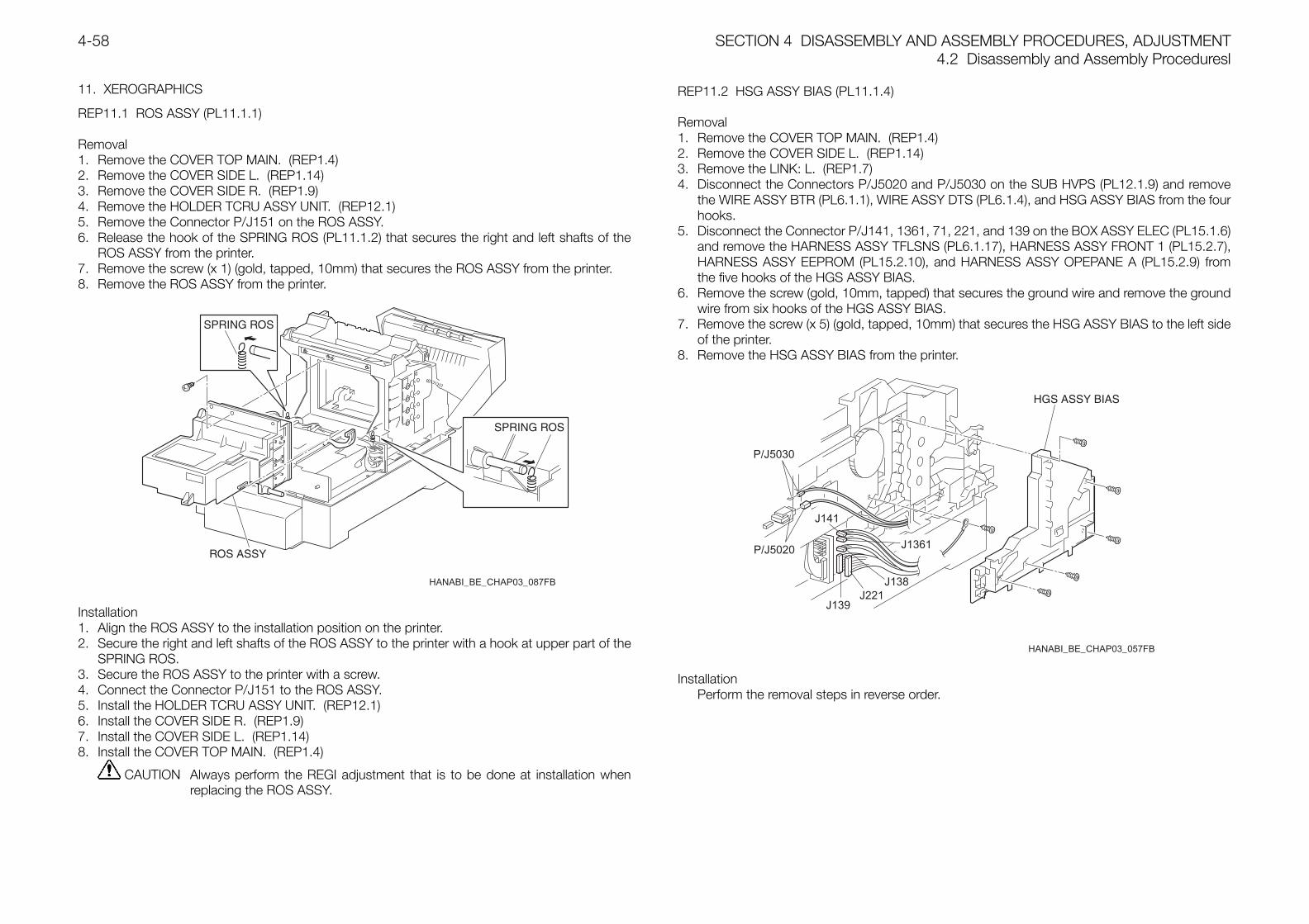
SECTION 4 DISASSEMBLY AND ASSEMBLY PROCEDURES, ADJUSTMENT4.2 Disassembly and Assembly Proceduresl
4-58
11. XEROGRAPHICS
REP11.1 ROS ASSY (PL11.1.1)
Removal1. Remove the COVER TOP MAIN. (REP1.4)2. Remove the COVER SIDE L. (REP1.14)3. Remove the COVER SIDE R. (REP1.9)4. Remove the HOLDER TCRU ASSY UNIT. (REP12.1)5. Remove the Connector P/J151 on the ROS ASSY.6. Release the hook of the SPRING ROS (PL11.1.2) that secures the right and left shafts of the
ROS ASSY from the printer.7. Remove the screw (x 1) (gold, tapped, 10mm) that secures the ROS ASSY from the printer.8. Remove the ROS ASSY from the printer.
HANABI_BE_CHAP03_087FB
Installation1. Align the ROS ASSY to the installation position on the printer.2. Secure the right and left shafts of the ROS ASSY to the printer with a hook at upper part of the
SPRING ROS.3. Secure the ROS ASSY to the printer with a screw.4. Connect the Connector P/J151 to the ROS ASSY.5. Install the HOLDER TCRU ASSY UNIT. (REP12.1)6. Install the COVER SIDE R. (REP1.9)7. Install the COVER SIDE L. (REP1.14)8. Install the COVER TOP MAIN. (REP1.4)
CAUTION Always perform the REGI adjustment that is to be done at installation whenreplacing the ROS ASSY.
REP11.2 HSG ASSY BIAS (PL11.1.4)
Removal1. Remove the COVER TOP MAIN. (REP1.4)2. Remove the COVER SIDE L. (REP1.14)3. Remove the LINK: L. (REP1.7)4. Disconnect the Connectors P/J5020 and P/J5030 on the SUB HVPS (PL12.1.9) and remove
the WIRE ASSY BTR (PL6.1.1), WIRE ASSY DTS (PL6.1.4), and HSG ASSY BIAS from the fourhooks.
5. Disconnect the Connector P/J141, 1361, 71, 221, and 139 on the BOX ASSY ELEC (PL15.1.6)and remove the HARNESS ASSY TFLSNS (PL6.1.17), HARNESS ASSY FRONT 1 (PL15.2.7),HARNESS ASSY EEPROM (PL15.2.10), and HARNESS ASSY OPEPANE A (PL15.2.9) fromthe five hooks of the HGS ASSY BIAS.
6. Remove the screw (gold, 10mm, tapped) that secures the ground wire and remove the groundwire from six hooks of the HGS ASSY BIAS.
7. Remove the screw (x 5) (gold, tapped, 10mm) that secures the HSG ASSY BIAS to the left sideof the printer.
8. Remove the HSG ASSY BIAS from the printer.
HANABI_BE_CHAP03_057FB
P/J5030
P/J5020
J221J139
J141
J1361
J138
InstallationPerform the removal steps in reverse order.
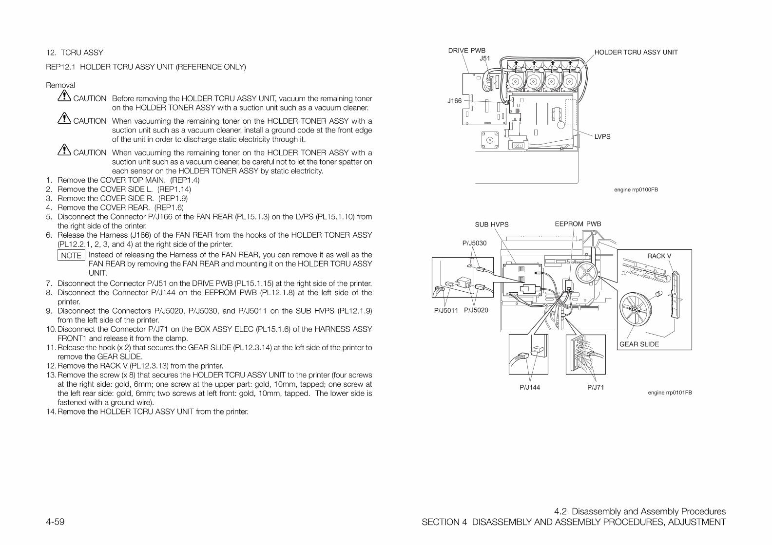
4.2 Disassembly and Assembly ProceduresSECTION 4 DISASSEMBLY AND ASSEMBLY PROCEDURES, ADJUSTMENT4-59
12. TCRU ASSY
REP12.1 HOLDER TCRU ASSY UNIT (REFERENCE ONLY)
Removal
CAUTION Before removing the HOLDER TCRU ASSY UNIT, vacuum the remaining toneron the HOLDER TONER ASSY with a suction unit such as a vacuum cleaner.
CAUTION When vacuuming the remaining toner on the HOLDER TONER ASSY with asuction unit such as a vacuum cleaner, install a ground code at the front edgeof the unit in order to discharge static electricity through it.
CAUTION When vacuuming the remaining toner on the HOLDER TONER ASSY with asuction unit such as a vacuum cleaner, be careful not to let the toner spatter oneach sensor on the HOLDER TONER ASSY by static electricity.
1. Remove the COVER TOP MAIN. (REP1.4)2. Remove the COVER SIDE L. (REP1.14)3. Remove the COVER SIDE R. (REP1.9)4. Remove the COVER REAR. (REP1.6)5. Disconnect the Connector P/J166 of the FAN REAR (PL15.1.3) on the LVPS (PL15.1.10) from
the right side of the printer.6. Release the Harness (J166) of the FAN REAR from the hooks of the HOLDER TONER ASSY
(PL12.2.1, 2, 3, and 4) at the right side of the printer.Instead of releasing the Harness of the FAN REAR, you can remove it as well as theFAN REAR by removing the FAN REAR and mounting it on the HOLDER TCRU ASSYUNIT.
7. Disconnect the Connector P/J51 on the DRIVE PWB (PL15.1.15) at the right side of the printer.8. Disconnect the Connector P/J144 on the EEPROM PWB (PL12.1.8) at the left side of the
printer.9. Disconnect the Connectors P/J5020, P/J5030, and P/J5011 on the SUB HVPS (PL12.1.9)
from the left side of the printer.10.Disconnect the Connector P/J71 on the BOX ASSY ELEC (PL15.1.6) of the HARNESS ASSY
FRONT1 and release it from the clamp.11.Release the hook (x 2) that secures the GEAR SLIDE (PL12.3.14) at the left side of the printer to
remove the GEAR SLIDE.12.Remove the RACK V (PL12.3.13) from the printer.13.Remove the screw (x 8) that secures the HOLDER TCRU ASSY UNIT to the printer (four screws
at the right side: gold, 6mm; one screw at the upper part: gold, 10mm, tapped; one screw atthe left rear side: gold, 6mm; two screws at left front: gold, 10mm, tapped. The lower side isfastened with a ground wire).
14.Remove the HOLDER TCRU ASSY UNIT from the printer.
J51
J166
engine rrp0100FB
P/J5030
P/J144 P/J71
P/J5011 P/J5020
engine rrp0101FB
NOTE
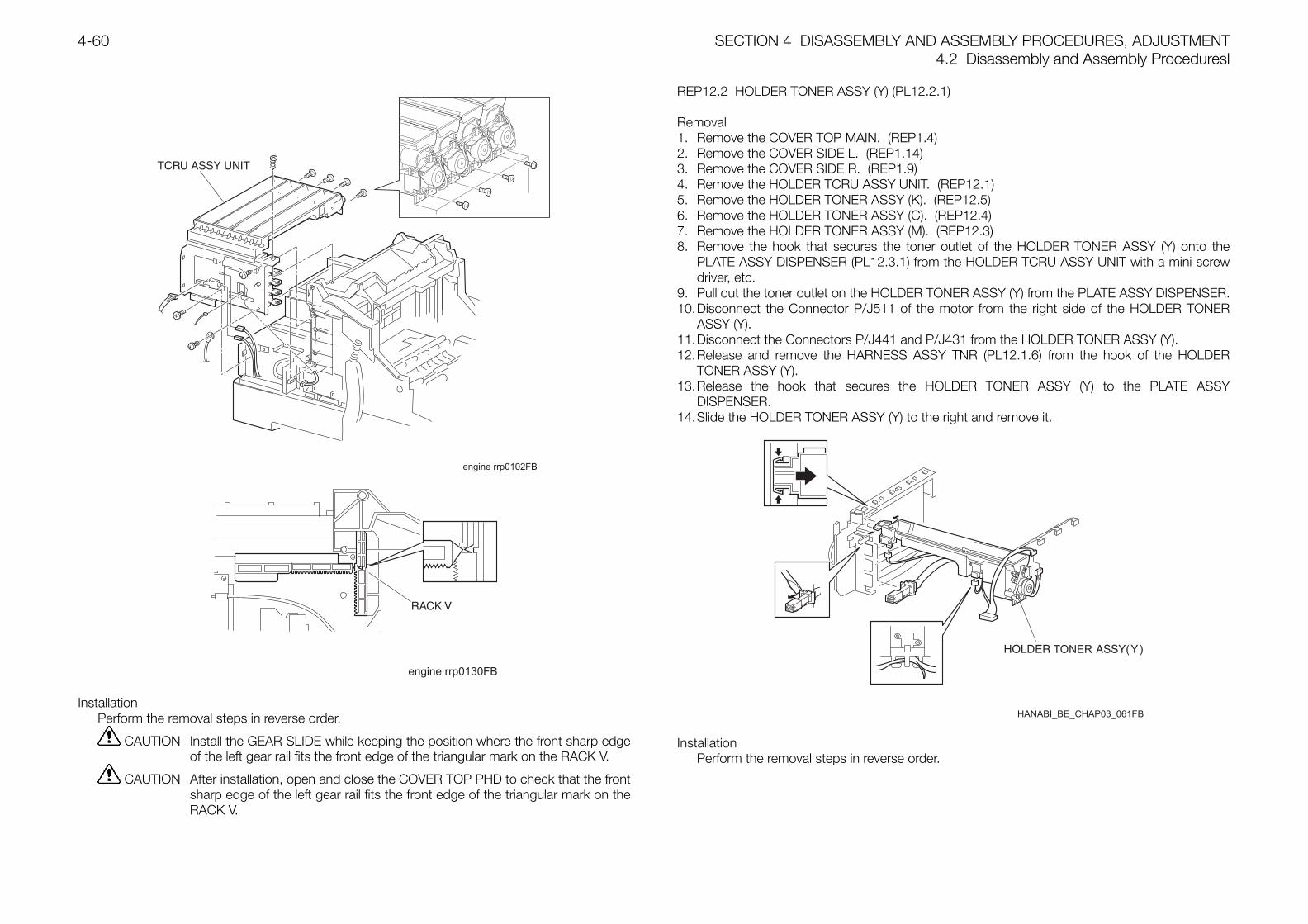
SECTION 4 DISASSEMBLY AND ASSEMBLY PROCEDURES, ADJUSTMENT4.2 Disassembly and Assembly Proceduresl
4-60
engine rrp0102FB
engine rrp0130FB
InstallationPerform the removal steps in reverse order.
CAUTION Install the GEAR SLIDE while keeping the position where the front sharp edgeof the left gear rail fits the front edge of the triangular mark on the RACK V.
CAUTION After installation, open and close the COVER TOP PHD to check that the frontsharp edge of the left gear rail fits the front edge of the triangular mark on theRACK V.
REP12.2 HOLDER TONER ASSY (Y) (PL12.2.1)
Removal1. Remove the COVER TOP MAIN. (REP1.4)2. Remove the COVER SIDE L. (REP1.14)3. Remove the COVER SIDE R. (REP1.9)4. Remove the HOLDER TCRU ASSY UNIT. (REP12.1)5. Remove the HOLDER TONER ASSY (K). (REP12.5)6. Remove the HOLDER TONER ASSY (C). (REP12.4)7. Remove the HOLDER TONER ASSY (M). (REP12.3)8. Remove the hook that secures the toner outlet of the HOLDER TONER ASSY (Y) onto the
PLATE ASSY DISPENSER (PL12.3.1) from the HOLDER TCRU ASSY UNIT with a mini screwdriver, etc.
9. Pull out the toner outlet on the HOLDER TONER ASSY (Y) from the PLATE ASSY DISPENSER.10.Disconnect the Connector P/J511 of the motor from the right side of the HOLDER TONER
ASSY (Y).11.Disconnect the Connectors P/J441 and P/J431 from the HOLDER TONER ASSY (Y).12.Release and remove the HARNESS ASSY TNR (PL12.1.6) from the hook of the HOLDER
TONER ASSY (Y).13.Release the hook that secures the HOLDER TONER ASSY (Y) to the PLATE ASSY
DISPENSER.14.Slide the HOLDER TONER ASSY (Y) to the right and remove it.
InstallationPerform the removal steps in reverse order.
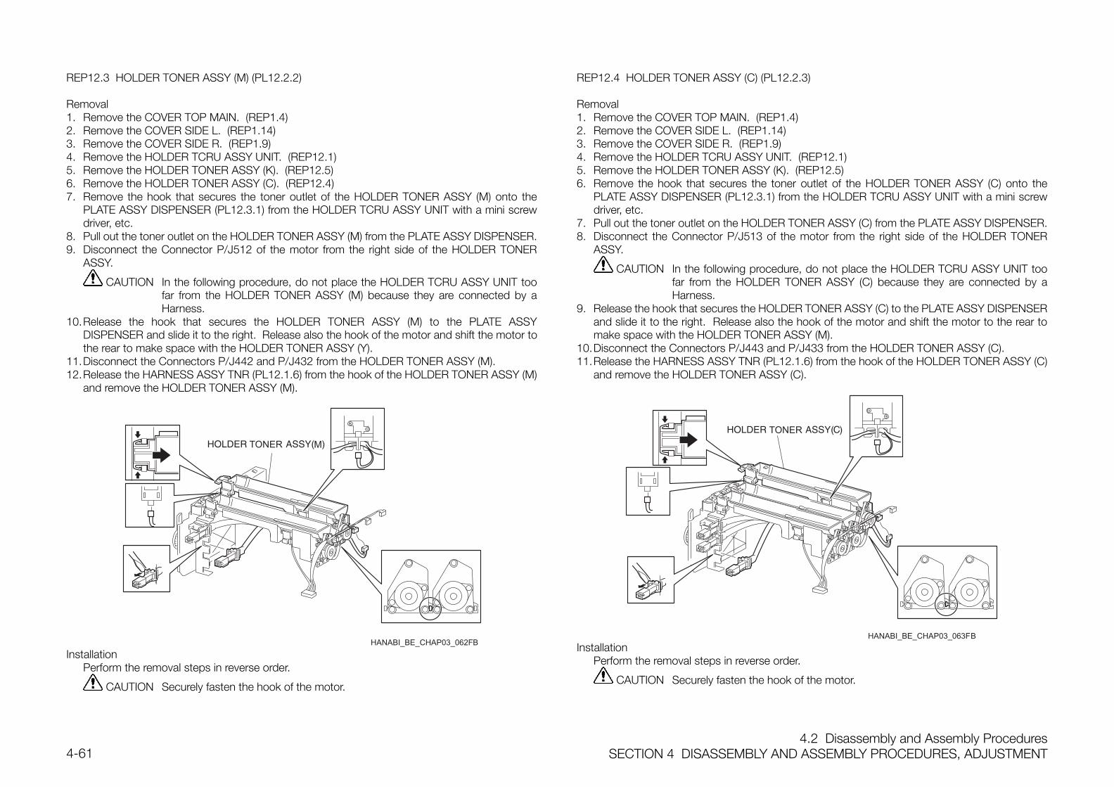
4.2 Disassembly and Assembly ProceduresSECTION 4 DISASSEMBLY AND ASSEMBLY PROCEDURES, ADJUSTMENT4-61
REP12.3 HOLDER TONER ASSY (M) (PL12.2.2)
Removal1. Remove the COVER TOP MAIN. (REP1.4)2. Remove the COVER SIDE L. (REP1.14)3. Remove the COVER SIDE R. (REP1.9)4. Remove the HOLDER TCRU ASSY UNIT. (REP12.1)5. Remove the HOLDER TONER ASSY (K). (REP12.5)6. Remove the HOLDER TONER ASSY (C). (REP12.4)7. Remove the hook that secures the toner outlet of the HOLDER TONER ASSY (M) onto the
PLATE ASSY DISPENSER (PL12.3.1) from the HOLDER TCRU ASSY UNIT with a mini screwdriver, etc.
8. Pull out the toner outlet on the HOLDER TONER ASSY (M) from the PLATE ASSY DISPENSER.9. Disconnect the Connector P/J512 of the motor from the right side of the HOLDER TONER
ASSY.
CAUTION In the following procedure, do not place the HOLDER TCRU ASSY UNIT toofar from the HOLDER TONER ASSY (M) because they are connected by aHarness.
10.Release the hook that secures the HOLDER TONER ASSY (M) to the PLATE ASSYDISPENSER and slide it to the right. Release also the hook of the motor and shift the motor tothe rear to make space with the HOLDER TONER ASSY (Y).
11.Disconnect the Connectors P/J442 and P/J432 from the HOLDER TONER ASSY (M).12.Release the HARNESS ASSY TNR (PL12.1.6) from the hook of the HOLDER TONER ASSY (M)
and remove the HOLDER TONER ASSY (M).
InstallationPerform the removal steps in reverse order.
CAUTION Securely fasten the hook of the motor.
REP12.4 HOLDER TONER ASSY (C) (PL12.2.3)
Removal1. Remove the COVER TOP MAIN. (REP1.4)2. Remove the COVER SIDE L. (REP1.14)3. Remove the COVER SIDE R. (REP1.9)4. Remove the HOLDER TCRU ASSY UNIT. (REP12.1)5. Remove the HOLDER TONER ASSY (K). (REP12.5)6. Remove the hook that secures the toner outlet of the HOLDER TONER ASSY (C) onto the
PLATE ASSY DISPENSER (PL12.3.1) from the HOLDER TCRU ASSY UNIT with a mini screwdriver, etc.
7. Pull out the toner outlet on the HOLDER TONER ASSY (C) from the PLATE ASSY DISPENSER.8. Disconnect the Connector P/J513 of the motor from the right side of the HOLDER TONER
ASSY.
CAUTION In the following procedure, do not place the HOLDER TCRU ASSY UNIT toofar from the HOLDER TONER ASSY (C) because they are connected by aHarness.
9. Release the hook that secures the HOLDER TONER ASSY (C) to the PLATE ASSY DISPENSERand slide it to the right. Release also the hook of the motor and shift the motor to the rear tomake space with the HOLDER TONER ASSY (M).
10.Disconnect the Connectors P/J443 and P/J433 from the HOLDER TONER ASSY (C).11.Release the HARNESS ASSY TNR (PL12.1.6) from the hook of the HOLDER TONER ASSY (C)
and remove the HOLDER TONER ASSY (C).
InstallationPerform the removal steps in reverse order.
CAUTION Securely fasten the hook of the motor.
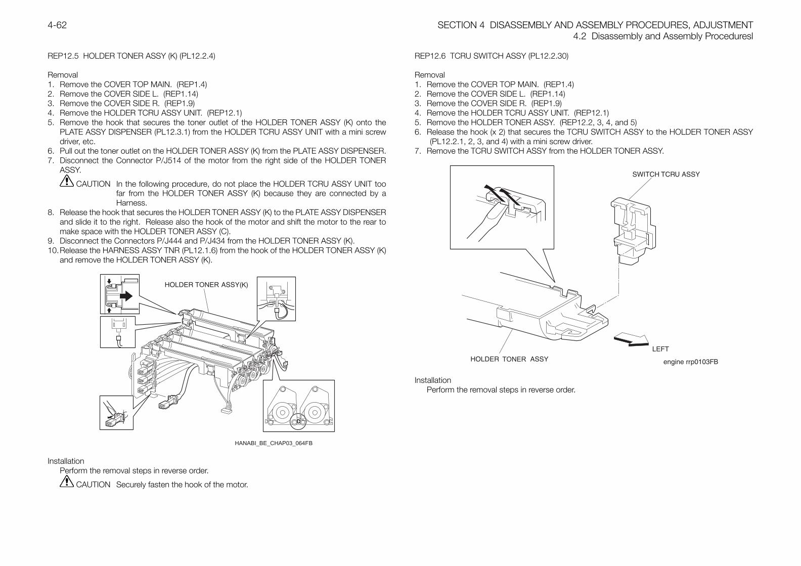
SECTION 4 DISASSEMBLY AND ASSEMBLY PROCEDURES, ADJUSTMENT4.2 Disassembly and Assembly Proceduresl
4-62
REP12.5 HOLDER TONER ASSY (K) (PL12.2.4)
Removal1. Remove the COVER TOP MAIN. (REP1.4)2. Remove the COVER SIDE L. (REP1.14)3. Remove the COVER SIDE R. (REP1.9)4. Remove the HOLDER TCRU ASSY UNIT. (REP12.1)5. Remove the hook that secures the toner outlet of the HOLDER TONER ASSY (K) onto the
PLATE ASSY DISPENSER (PL12.3.1) from the HOLDER TCRU ASSY UNIT with a mini screwdriver, etc.
6. Pull out the toner outlet on the HOLDER TONER ASSY (K) from the PLATE ASSY DISPENSER.7. Disconnect the Connector P/J514 of the motor from the right side of the HOLDER TONER
ASSY.
CAUTION In the following procedure, do not place the HOLDER TCRU ASSY UNIT toofar from the HOLDER TONER ASSY (K) because they are connected by aHarness.
8. Release the hook that secures the HOLDER TONER ASSY (K) to the PLATE ASSY DISPENSERand slide it to the right. Release also the hook of the motor and shift the motor to the rear tomake space with the HOLDER TONER ASSY (C).
9. Disconnect the Connectors P/J444 and P/J434 from the HOLDER TONER ASSY (K).10.Release the HARNESS ASSY TNR (PL12.1.6) from the hook of the HOLDER TONER ASSY (K)
and remove the HOLDER TONER ASSY (K).
InstallationPerform the removal steps in reverse order.
CAUTION Securely fasten the hook of the motor.
REP12.6 TCRU SWITCH ASSY (PL12.2.30)
Removal1. Remove the COVER TOP MAIN. (REP1.4)2. Remove the COVER SIDE L. (REP1.14)3. Remove the COVER SIDE R. (REP1.9)4. Remove the HOLDER TCRU ASSY UNIT. (REP12.1)5. Remove the HOLDER TONER ASSY. (REP12.2, 3, 4, and 5)6. Release the hook (x 2) that secures the TCRU SWITCH ASSY to the HOLDER TONER ASSY
(PL12.2.1, 2, 3, and 4) with a mini screw driver.7. Remove the TCRU SWITCH ASSY from the HOLDER TONER ASSY.
InstallationPerform the removal steps in reverse order.
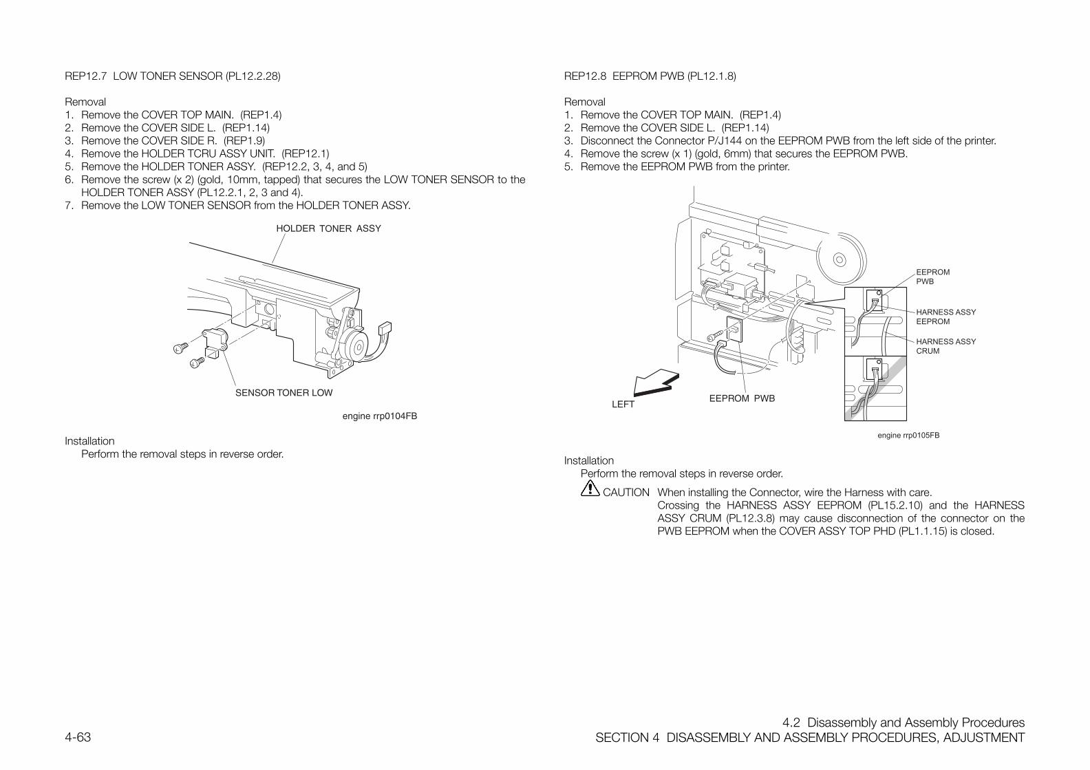
4.2 Disassembly and Assembly ProceduresSECTION 4 DISASSEMBLY AND ASSEMBLY PROCEDURES, ADJUSTMENT4-63
REP12.7 LOW TONER SENSOR (PL12.2.28)
Removal1. Remove the COVER TOP MAIN. (REP1.4)2. Remove the COVER SIDE L. (REP1.14)3. Remove the COVER SIDE R. (REP1.9)4. Remove the HOLDER TCRU ASSY UNIT. (REP12.1)5. Remove the HOLDER TONER ASSY. (REP12.2, 3, 4, and 5)6. Remove the screw (x 2) (gold, 10mm, tapped) that secures the LOW TONER SENSOR to the
HOLDER TONER ASSY (PL12.2.1, 2, 3 and 4).7. Remove the LOW TONER SENSOR from the HOLDER TONER ASSY.
InstallationPerform the removal steps in reverse order.
REP12.8 EEPROM PWB (PL12.1.8)
Removal1. Remove the COVER TOP MAIN. (REP1.4)2. Remove the COVER SIDE L. (REP1.14)3. Disconnect the Connector P/J144 on the EEPROM PWB from the left side of the printer.4. Remove the screw (x 1) (gold, 6mm) that secures the EEPROM PWB.5. Remove the EEPROM PWB from the printer.
engine rrp0105FB
HARNESS ASSYEEPROM
HARNESS ASSYCRUM
EEPROMPWB
InstallationPerform the removal steps in reverse order.
CAUTION When installing the Connector, wire the Harness with care.Crossing the HARNESS ASSY EEPROM (PL15.2.10) and the HARNESSASSY CRUM (PL12.3.8) may cause disconnection of the connector on thePWB EEPROM when the COVER ASSY TOP PHD (PL1.1.15) is closed.
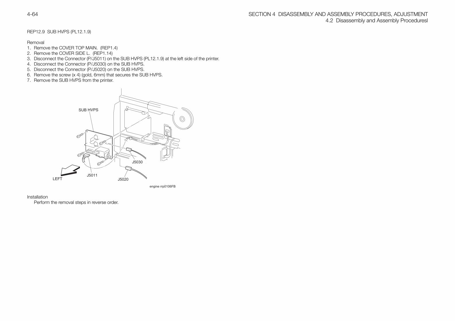
SECTION 4 DISASSEMBLY AND ASSEMBLY PROCEDURES, ADJUSTMENT4.2 Disassembly and Assembly Proceduresl
4-64
REP12.9 SUB HVPS (PL12.1.9)
Removal1. Remove the COVER TOP MAIN. (REP1.4)2. Remove the COVER SIDE L. (REP1.14)3. Disconnect the Connector (P/J5011) on the SUB HVPS (PL12.1.9) at the left side of the printer.4. Disconnect the Connector (P/J5030) on the SUB HVPS.5. Disconnect the Connector (P/J5020) on the SUB HVPS.6. Remove the screw (x 4) (gold, 6mm) that secures the SUB HVPS.7. Remove the SUB HVPS from the printer.
engine rrp0106FB
J5011J5020
J5030
InstallationPerform the removal steps in reverse order.
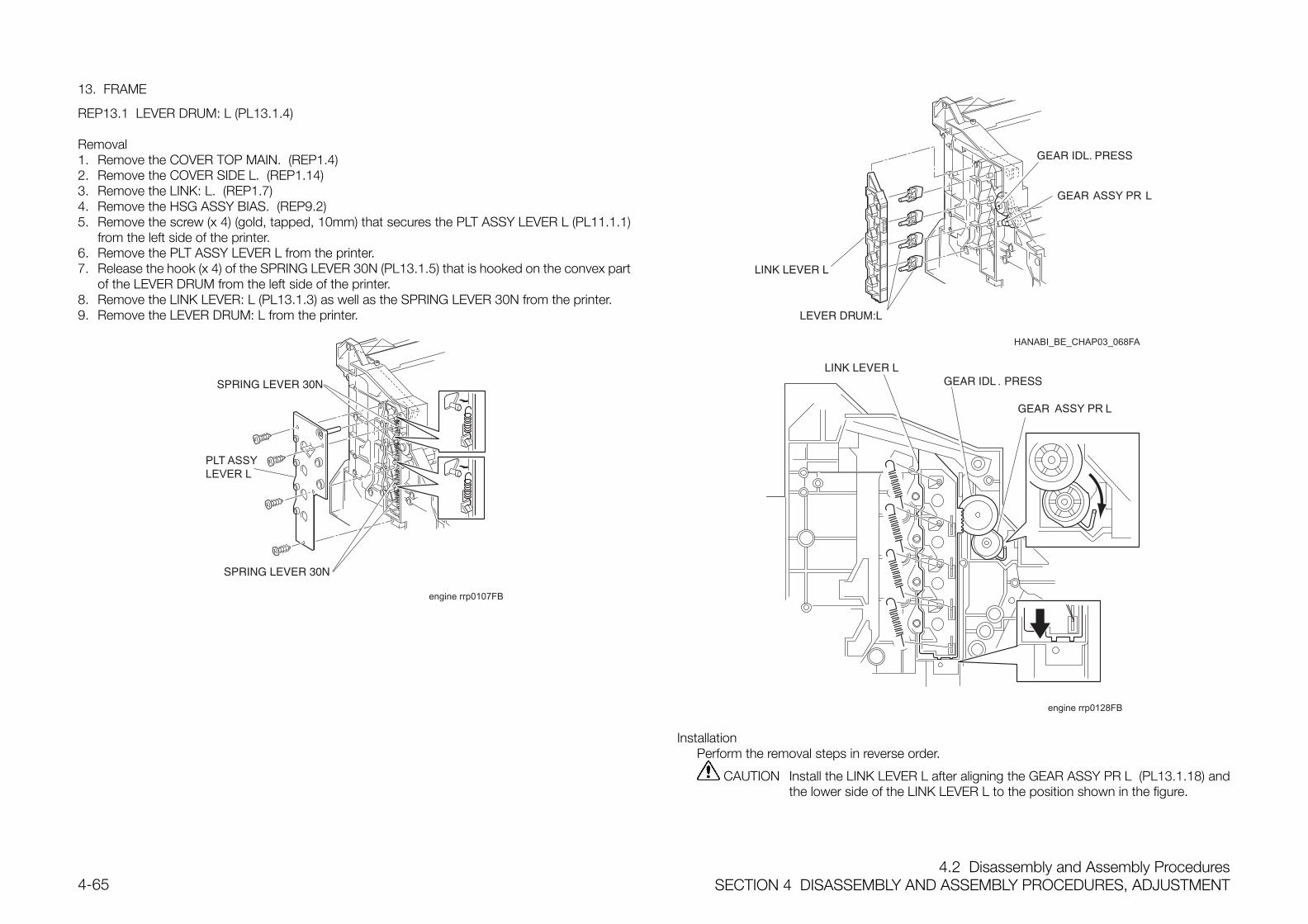
4.2 Disassembly and Assembly ProceduresSECTION 4 DISASSEMBLY AND ASSEMBLY PROCEDURES, ADJUSTMENT4-65
13. FRAME
REP13.1 LEVER DRUM: L (PL13.1.4)
Removal1. Remove the COVER TOP MAIN. (REP1.4)2. Remove the COVER SIDE L. (REP1.14)3. Remove the LINK: L. (REP1.7)4. Remove the HSG ASSY BIAS. (REP9.2)5. Remove the screw (x 4) (gold, tapped, 10mm) that secures the PLT ASSY LEVER L (PL11.1.1)
from the left side of the printer.6. Remove the PLT ASSY LEVER L from the printer.7. Release the hook (x 4) of the SPRING LEVER 30N (PL13.1.5) that is hooked on the convex part
of the LEVER DRUM from the left side of the printer.8. Remove the LINK LEVER: L (PL13.1.3) as well as the SPRING LEVER 30N from the printer.9. Remove the LEVER DRUM: L from the printer.
engine rrp0107FB
PLT ASSYLEVER L
engine rrp0128FB
.
InstallationPerform the removal steps in reverse order.
CAUTION Install the LINK LEVER L after aligning the GEAR ASSY PR L (PL13.1.18) andthe lower side of the LINK LEVER L to the position shown in the figure.
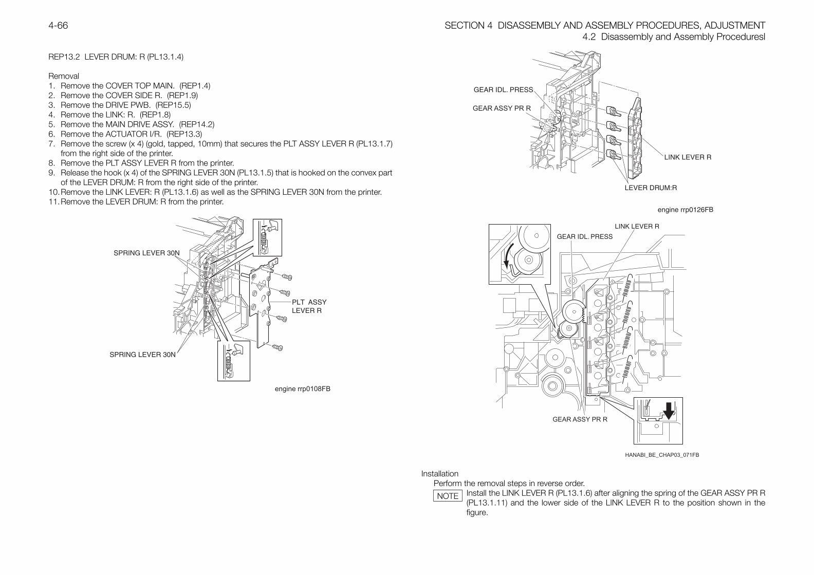
SECTION 4 DISASSEMBLY AND ASSEMBLY PROCEDURES, ADJUSTMENT4.2 Disassembly and Assembly Proceduresl
4-66
REP13.2 LEVER DRUM: R (PL13.1.4)
Removal1. Remove the COVER TOP MAIN. (REP1.4)2. Remove the COVER SIDE R. (REP1.9)3. Remove the DRIVE PWB. (REP15.5)4. Remove the LINK: R. (REP1.8)5. Remove the MAIN DRIVE ASSY. (REP14.2)6. Remove the ACTUATOR I/R. (REP13.3)7. Remove the screw (x 4) (gold, tapped, 10mm) that secures the PLT ASSY LEVER R (PL13.1.7)
from the right side of the printer.8. Remove the PLT ASSY LEVER R from the printer.9. Release the hook (x 4) of the SPRING LEVER 30N (PL13.1.5) that is hooked on the convex part
of the LEVER DRUM: R from the right side of the printer.10.Remove the LINK LEVER: R (PL13.1.6) as well as the SPRING LEVER 30N from the printer.11.Remove the LEVER DRUM: R from the printer.
engine rrp0108FB
HANABI_BE_CHAP03_071FB
InstallationPerform the removal steps in reverse order.
Install the LINK LEVER R (PL13.1.6) after aligning the spring of the GEAR ASSY PR R(PL13.1.11) and the lower side of the LINK LEVER R to the position shown in thefigure.
NOTE
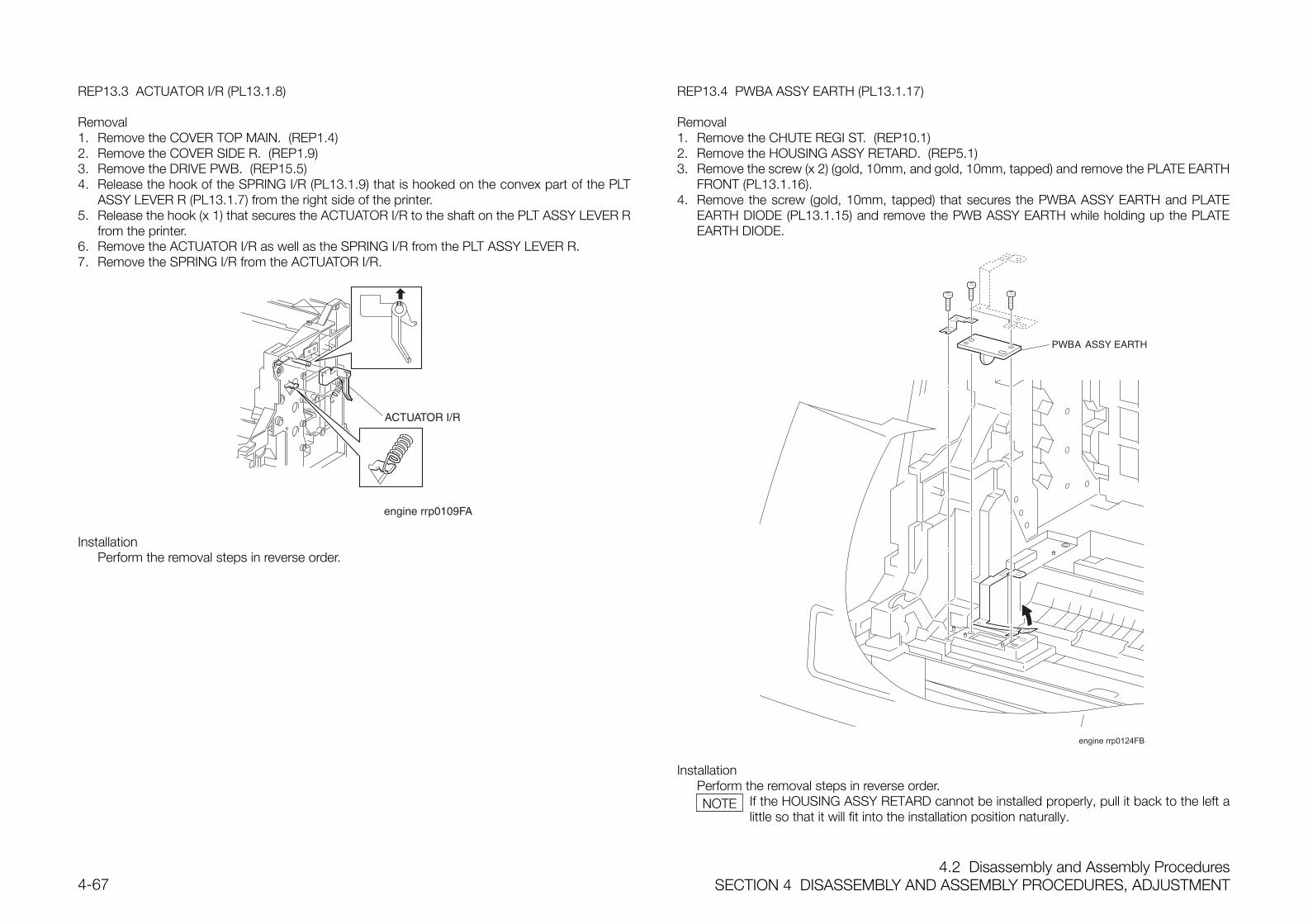
4.2 Disassembly and Assembly ProceduresSECTION 4 DISASSEMBLY AND ASSEMBLY PROCEDURES, ADJUSTMENT4-67
REP13.3 ACTUATOR I/R (PL13.1.8)
Removal1. Remove the COVER TOP MAIN. (REP1.4)2. Remove the COVER SIDE R. (REP1.9)3. Remove the DRIVE PWB. (REP15.5)4. Release the hook of the SPRING I/R (PL13.1.9) that is hooked on the convex part of the PLT
ASSY LEVER R (PL13.1.7) from the right side of the printer.5. Release the hook (x 1) that secures the ACTUATOR I/R to the shaft on the PLT ASSY LEVER R
from the printer.6. Remove the ACTUATOR I/R as well as the SPRING I/R from the PLT ASSY LEVER R.7. Remove the SPRING I/R from the ACTUATOR I/R.
InstallationPerform the removal steps in reverse order.
REP13.4 PWBA ASSY EARTH (PL13.1.17)
Removal1. Remove the CHUTE REGI ST. (REP10.1)2. Remove the HOUSING ASSY RETARD. (REP5.1)3. Remove the screw (x 2) (gold, 10mm, and gold, 10mm, tapped) and remove the PLATE EARTH
FRONT (PL13.1.16).4. Remove the screw (gold, 10mm, tapped) that secures the PWBA ASSY EARTH and PLATE
EARTH DIODE (PL13.1.15) and remove the PWB ASSY EARTH while holding up the PLATEEARTH DIODE.
engine rrp0124FB
InstallationPerform the removal steps in reverse order.
If the HOUSING ASSY RETARD cannot be installed properly, pull it back to the left alittle so that it will fit into the installation position naturally.
NOTE
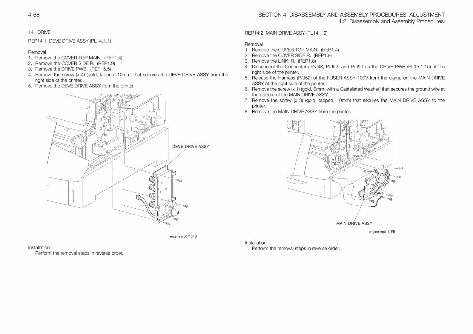
SECTION 4 DISASSEMBLY AND ASSEMBLY PROCEDURES, ADJUSTMENT4.2 Disassembly and Assembly Proceduresl
4-68
14. DRIVE
REP14.1 DEVE DRIVE ASSY (PL14.1.1)
Removal1. Remove the COVER TOP MAIN. (REP1.4)2. Remove the COVER SIDE R. (REP1.9)3. Remove the DRIVE PWB. (REP15.5)4. Remove the screw (x 4) (gold, tapped, 10mm) that secures the DEVE DRIVE ASSY from the
right side of the printer.5. Remove the DEVE DRIVE ASSY from the printer.
engine rrp0110FB
InstallationPerform the removal steps in reverse order.
REP14.2 MAIN DRIVE ASSY (PL14.1.9)
Removal1. Remove the COVER TOP MAIN. (REP1.4)2. Remove the COVER SIDE R. (REP1.9)3. Remove the LINK: R. (REP1.8)4. Disconnect the Connectors P/J48, P/J52, and P/J50 on the DRIVE PWB (PL15.1.15) at the
right side of the printer.5. Release the Harness (P/J52) of the FUSER ASSY 100V from the clamp on the MAIN DRIVE
ASSY at the right side of the printer.6. Remove the screw (x 1) (gold, 6mm, with a Castellated Washer) that secures the ground wire at
the bottom of the MAIN DRIVE ASSY.7. Remove the screw (x 3) (gold, tapped, 10mm) that secures the MAIN DRIVE ASSY to the
printer.8. Remove the MAIN DRIVE ASSY from the printer.
engine rrp0111FB
J52J48
J50
InstallationPerform the removal steps in reverse order.
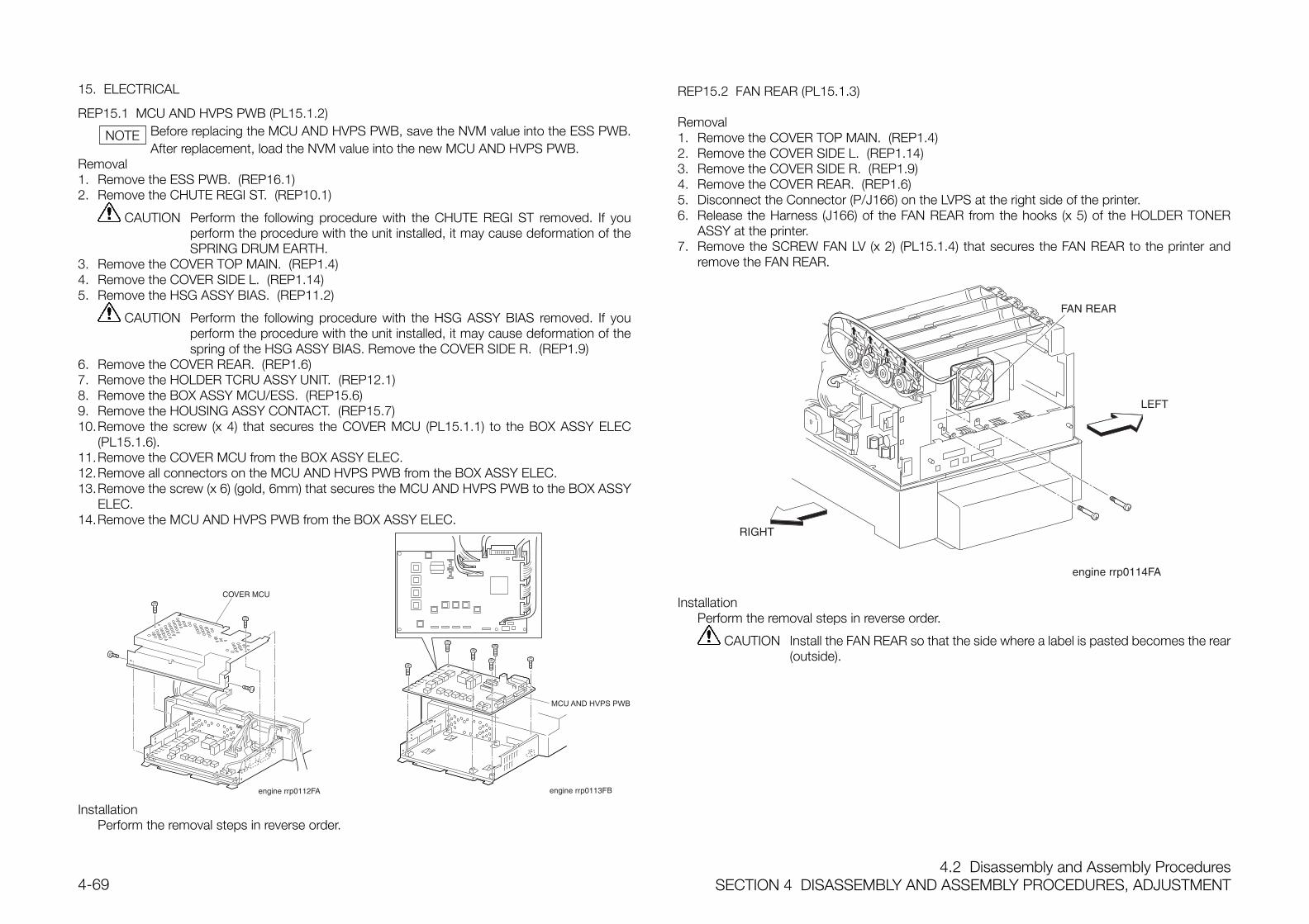
4.2 Disassembly and Assembly ProceduresSECTION 4 DISASSEMBLY AND ASSEMBLY PROCEDURES, ADJUSTMENT4-69
15. ELECTRICAL
REP15.1 MCU AND HVPS PWB (PL15.1.2)Before replacing the MCU AND HVPS PWB, save the NVM value into the ESS PWB.After replacement, load the NVM value into the new MCU AND HVPS PWB.
Removal1. Remove the ESS PWB. (REP16.1)2. Remove the CHUTE REGI ST. (REP10.1)
CAUTION Perform the following procedure with the CHUTE REGI ST removed. If youperform the procedure with the unit installed, it may cause deformation of theSPRING DRUM EARTH.
3. Remove the COVER TOP MAIN. (REP1.4)4. Remove the COVER SIDE L. (REP1.14)5. Remove the HSG ASSY BIAS. (REP11.2)
CAUTION Perform the following procedure with the HSG ASSY BIAS removed. If youperform the procedure with the unit installed, it may cause deformation of thespring of the HSG ASSY BIAS. Remove the COVER SIDE R. (REP1.9)
6. Remove the COVER REAR. (REP1.6)7. Remove the HOLDER TCRU ASSY UNIT. (REP12.1)8. Remove the BOX ASSY MCU/ESS. (REP15.6)9. Remove the HOUSING ASSY CONTACT. (REP15.7)10.Remove the screw (x 4) that secures the COVER MCU (PL15.1.1) to the BOX ASSY ELEC
(PL15.1.6).11.Remove the COVER MCU from the BOX ASSY ELEC.12.Remove all connectors on the MCU AND HVPS PWB from the BOX ASSY ELEC.13.Remove the screw (x 6) (gold, 6mm) that secures the MCU AND HVPS PWB to the BOX ASSY
ELEC.14.Remove the MCU AND HVPS PWB from the BOX ASSY ELEC.
MCU AND HVPS PWB
B
InstallationPerform the removal steps in reverse order.
REP15.2 FAN REAR (PL15.1.3)
Removal1. Remove the COVER TOP MAIN. (REP1.4)2. Remove the COVER SIDE L. (REP1.14)3. Remove the COVER SIDE R. (REP1.9)4. Remove the COVER REAR. (REP1.6)5. Disconnect the Connector (P/J166) on the LVPS at the right side of the printer.6. Release the Harness (J166) of the FAN REAR from the hooks (x 5) of the HOLDER TONER
ASSY at the printer.7. Remove the SCREW FAN LV (x 2) (PL15.1.4) that secures the FAN REAR to the printer and
remove the FAN REAR.
InstallationPerform the removal steps in reverse order.
CAUTION Install the FAN REAR so that the side where a label is pasted becomes the rear(outside).
NOTE
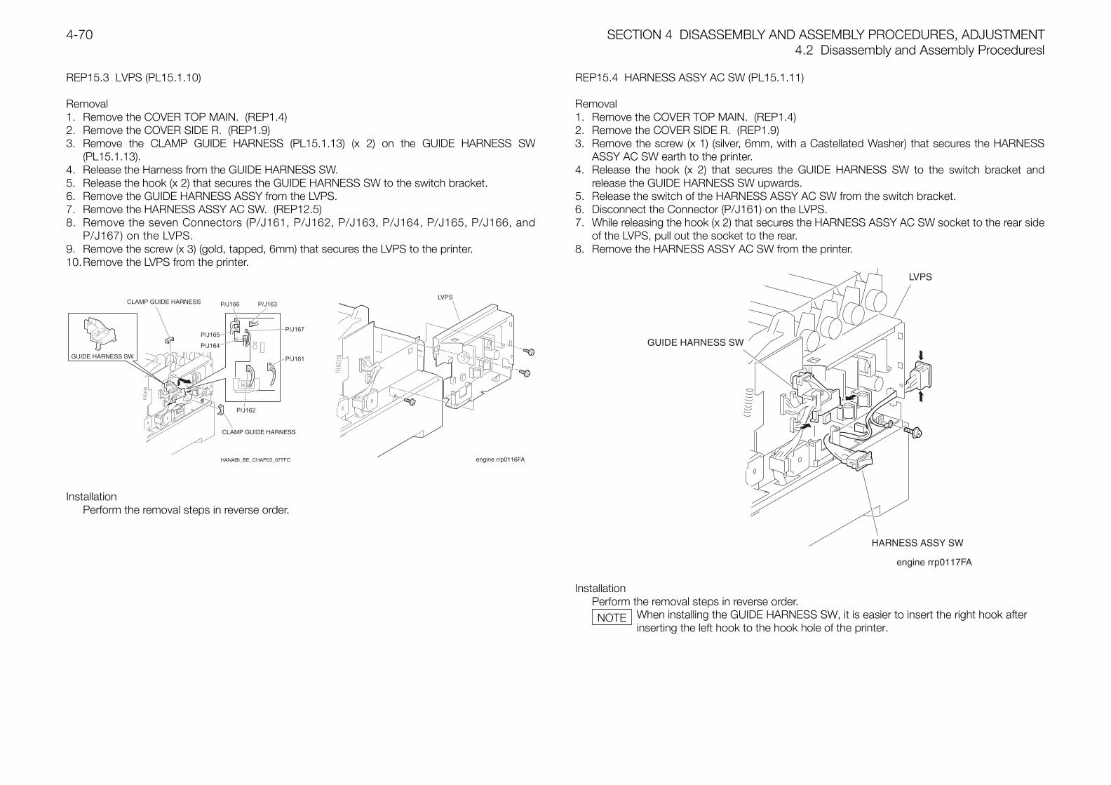
SECTION 4 DISASSEMBLY AND ASSEMBLY PROCEDURES, ADJUSTMENT4.2 Disassembly and Assembly Proceduresl
4-70
REP15.3 LVPS (PL15.1.10)
Removal1. Remove the COVER TOP MAIN. (REP1.4)2. Remove the COVER SIDE R. (REP1.9)3. Remove the CLAMP GUIDE HARNESS (PL15.1.13) (x 2) on the GUIDE HARNESS SW
(PL15.1.13).4. Release the Harness from the GUIDE HARNESS SW.5. Release the hook (x 2) that secures the GUIDE HARNESS SW to the switch bracket.6. Remove the GUIDE HARNESS ASSY from the LVPS.7. Remove the HARNESS ASSY AC SW. (REP12.5)8. Remove the seven Connectors (P/J161, P/J162, P/J163, P/J164, P/J165, P/J166, and
P/J167) on the LVPS.9. Remove the screw (x 3) (gold, tapped, 6mm) that secures the LVPS to the printer.10.Remove the LVPS from the printer.
HANABI_BE_CHAP03_077FC
P/J166 P/J163
P/J167
P/J161
P/J162
P/J164
P/J165
InstallationPerform the removal steps in reverse order.
REP15.4 HARNESS ASSY AC SW (PL15.1.11)
Removal1. Remove the COVER TOP MAIN. (REP1.4)2. Remove the COVER SIDE R. (REP1.9)3. Remove the screw (x 1) (silver, 6mm, with a Castellated Washer) that secures the HARNESS
ASSY AC SW earth to the printer.4. Release the hook (x 2) that secures the GUIDE HARNESS SW to the switch bracket and
release the GUIDE HARNESS SW upwards.5. Release the switch of the HARNESS ASSY AC SW from the switch bracket.6. Disconnect the Connector (P/J161) on the LVPS.7. While releasing the hook (x 2) that secures the HARNESS ASSY AC SW socket to the rear side
of the LVPS, pull out the socket to the rear.8. Remove the HARNESS ASSY AC SW from the printer.
InstallationPerform the removal steps in reverse order.
When installing the GUIDE HARNESS SW, it is easier to insert the right hook afterinserting the left hook to the hook hole of the printer.
NOTE
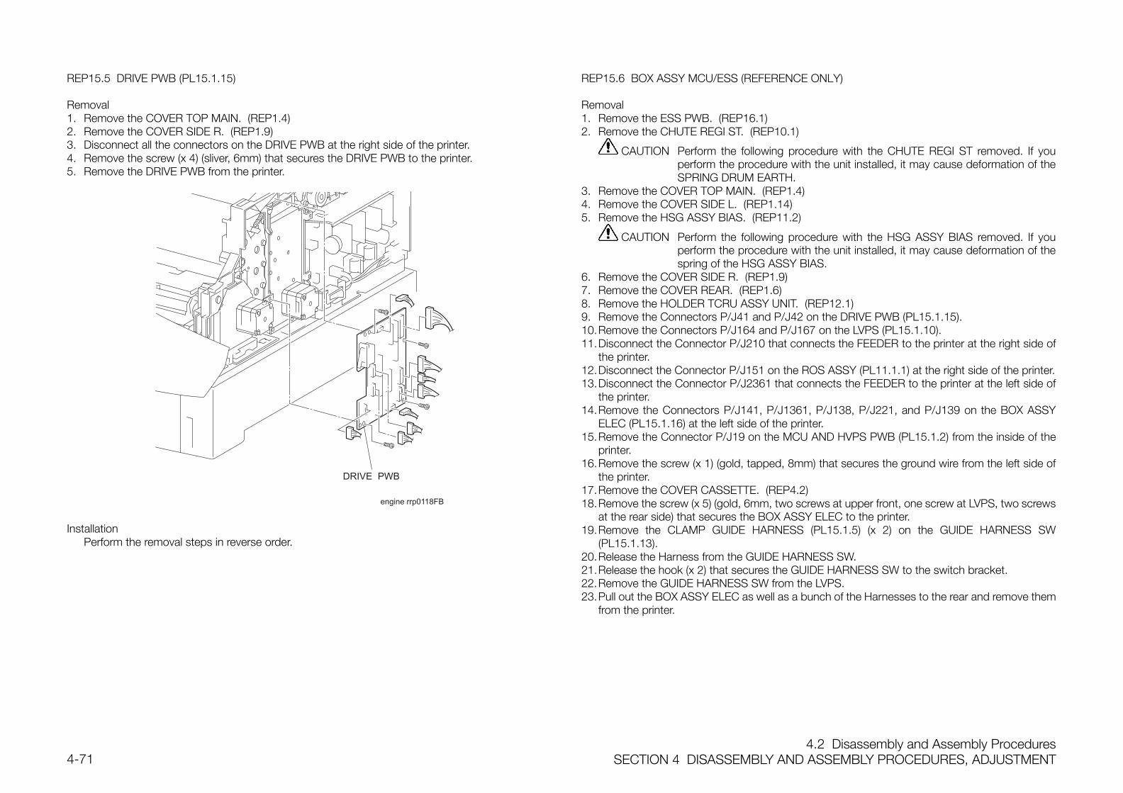
4.2 Disassembly and Assembly ProceduresSECTION 4 DISASSEMBLY AND ASSEMBLY PROCEDURES, ADJUSTMENT4-71
REP15.5 DRIVE PWB (PL15.1.15)
Removal1. Remove the COVER TOP MAIN. (REP1.4)2. Remove the COVER SIDE R. (REP1.9)3. Disconnect all the connectors on the DRIVE PWB at the right side of the printer.4. Remove the screw (x 4) (sliver, 6mm) that secures the DRIVE PWB to the printer.5. Remove the DRIVE PWB from the printer.
engine rrp0118FB
InstallationPerform the removal steps in reverse order.
REP15.6 BOX ASSY MCU/ESS (REFERENCE ONLY)
Removal1. Remove the ESS PWB. (REP16.1)2. Remove the CHUTE REGI ST. (REP10.1)
CAUTION Perform the following procedure with the CHUTE REGI ST removed. If youperform the procedure with the unit installed, it may cause deformation of theSPRING DRUM EARTH.
3. Remove the COVER TOP MAIN. (REP1.4)4. Remove the COVER SIDE L. (REP1.14)5. Remove the HSG ASSY BIAS. (REP11.2)
CAUTION Perform the following procedure with the HSG ASSY BIAS removed. If youperform the procedure with the unit installed, it may cause deformation of thespring of the HSG ASSY BIAS.
6. Remove the COVER SIDE R. (REP1.9)7. Remove the COVER REAR. (REP1.6)8. Remove the HOLDER TCRU ASSY UNIT. (REP12.1)9. Remove the Connectors P/J41 and P/J42 on the DRIVE PWB (PL15.1.15).10.Remove the Connectors P/J164 and P/J167 on the LVPS (PL15.1.10).11.Disconnect the Connector P/J210 that connects the FEEDER to the printer at the right side of
the printer.12.Disconnect the Connector P/J151 on the ROS ASSY (PL11.1.1) at the right side of the printer.13.Disconnect the Connector P/J2361 that connects the FEEDER to the printer at the left side of
the printer.14.Remove the Connectors P/J141, P/J1361, P/J138, P/J221, and P/J139 on the BOX ASSY
ELEC (PL15.1.16) at the left side of the printer.15.Remove the Connector P/J19 on the MCU AND HVPS PWB (PL15.1.2) from the inside of the
printer.16.Remove the screw (x 1) (gold, tapped, 8mm) that secures the ground wire from the left side of
the printer.17.Remove the COVER CASSETTE. (REP4.2)18.Remove the screw (x 5) (gold, 6mm, two screws at upper front, one screw at LVPS, two screws
at the rear side) that secures the BOX ASSY ELEC to the printer.19.Remove the CLAMP GUIDE HARNESS (PL15.1.5) (x 2) on the GUIDE HARNESS SW
(PL15.1.13).20.Release the Harness from the GUIDE HARNESS SW.21.Release the hook (x 2) that secures the GUIDE HARNESS SW to the switch bracket.22.Remove the GUIDE HARNESS SW from the LVPS.23.Pull out the BOX ASSY ELEC as well as a bunch of the Harnesses to the rear and remove them
from the printer.
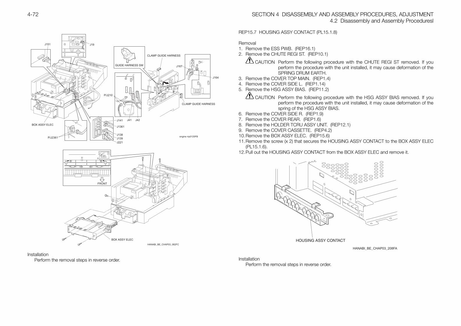
SECTION 4 DISASSEMBLY AND ASSEMBLY PROCEDURES, ADJUSTMENT4.2 Disassembly and Assembly Proceduresl
4-72
engine rrp0120FB
J151 J19
J141 J41 J42
J1361
J138
J167
J164
P/J210
J221J139P/J2361
HANABI_BE_CHAP03_082FC
InstallationPerform the removal steps in reverse order.
REP15.7 HOUSING ASSY CONTACT (PL15.1.8)
Removal1. Remove the ESS PWB. (REP16.1)2. Remove the CHUTE REGI ST. (REP10.1)
CAUTION Perform the following procedure with the CHUTE REGI ST removed. If youperform the procedure with the unit installed, it may cause deformation of theSPRING DRUM EARTH.
3. Remove the COVER TOP MAIN. (REP1.4)4. Remove the COVER SIDE L. (REP1.14)5. Remove the HSG ASSY BIAS. (REP11.2)
CAUTION Perform the following procedure with the HSG ASSY BIAS removed. If youperform the procedure with the unit installed, it may cause deformation of thespring of the HSG ASSY BIAS.
6. Remove the COVER SIDE R. (REP1.9)7. Remove the COVER REAR. (REP1.6)8. Remove the HOLDER TCRU ASSY UNIT. (REP12.1)9. Remove the COVER CASSETTE. (REP4.2)10.Remove the BOX ASSY ELEC. (REP15.6)11.Remove the screw (x 2) that secures the HOUSING ASSY CONTACT to the BOX ASSY ELEC
(PL15.1.6).12.Pull out the HOUSING ASSY CONTACT from the BOX ASSY ELEC and remove it.
HANABI_BE_CHAP03_208FA
InstallationPerform the removal steps in reverse order.
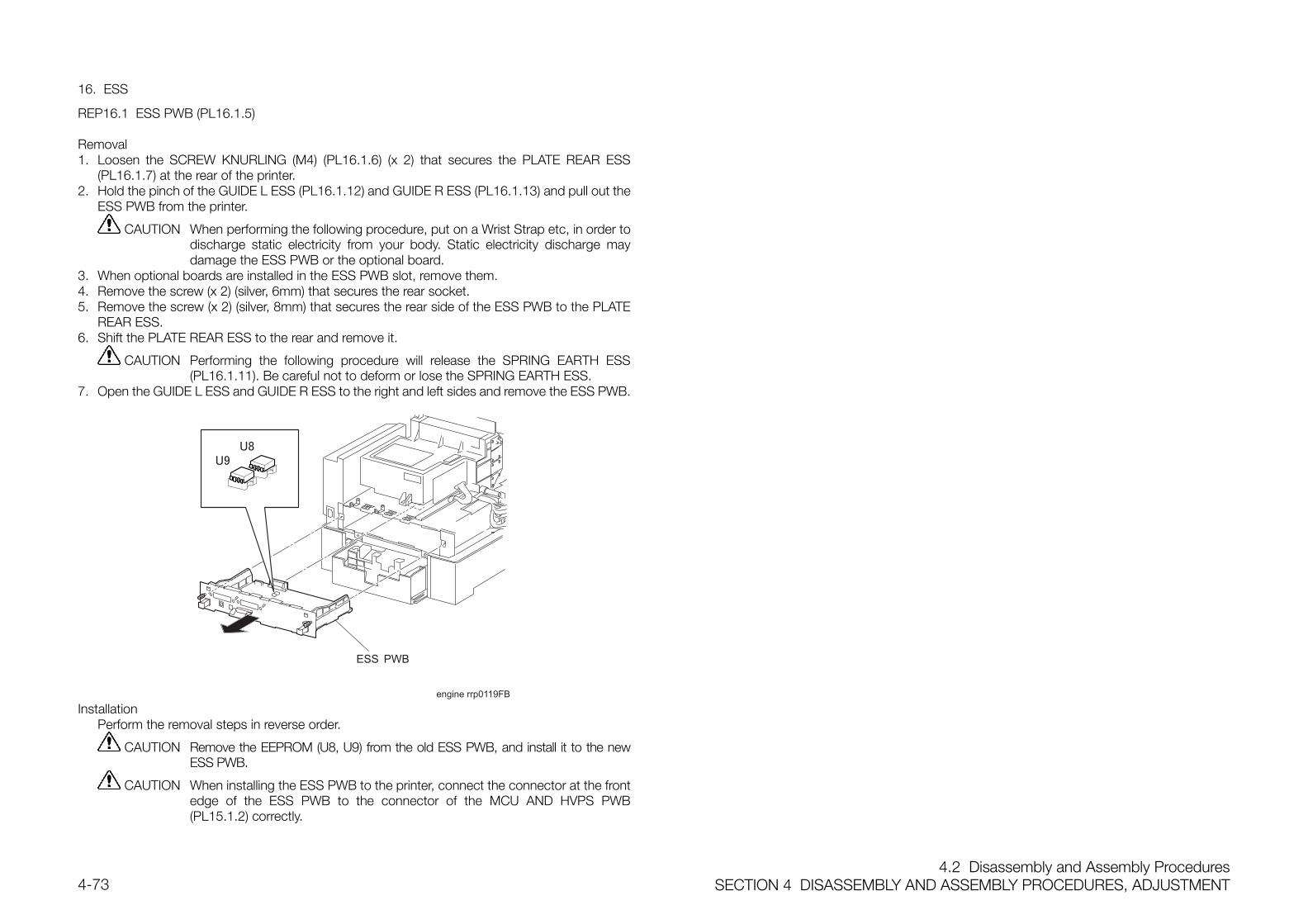
4.2 Disassembly and Assembly ProceduresSECTION 4 DISASSEMBLY AND ASSEMBLY PROCEDURES, ADJUSTMENT4-73
16. ESS
REP16.1 ESS PWB (PL16.1.5)
Removal1. Loosen the SCREW KNURLING (M4) (PL16.1.6) (x 2) that secures the PLATE REAR ESS
(PL16.1.7) at the rear of the printer.2. Hold the pinch of the GUIDE L ESS (PL16.1.12) and GUIDE R ESS (PL16.1.13) and pull out the
ESS PWB from the printer.
CAUTION When performing the following procedure, put on a Wrist Strap etc, in order todischarge static electricity from your body. Static electricity discharge maydamage the ESS PWB or the optional board.
3. When optional boards are installed in the ESS PWB slot, remove them.4. Remove the screw (x 2) (silver, 6mm) that secures the rear socket.5. Remove the screw (x 2) (silver, 8mm) that secures the rear side of the ESS PWB to the PLATE
REAR ESS.6. Shift the PLATE REAR ESS to the rear and remove it.
CAUTION Performing the following procedure will release the SPRING EARTH ESS(PL16.1.11). Be careful not to deform or lose the SPRING EARTH ESS.
7. Open the GUIDE L ESS and GUIDE R ESS to the right and left sides and remove the ESS PWB.
engine rrp0119FB
InstallationPerform the removal steps in reverse order.
CAUTION Remove the EEPROM (U8, U9) from the old ESS PWB, and install it to the newESS PWB.
CAUTION When installing the ESS PWB to the printer, connect the connector at the frontedge of the ESS PWB to the connector of the MCU AND HVPS PWB(PL15.1.2) correctly.
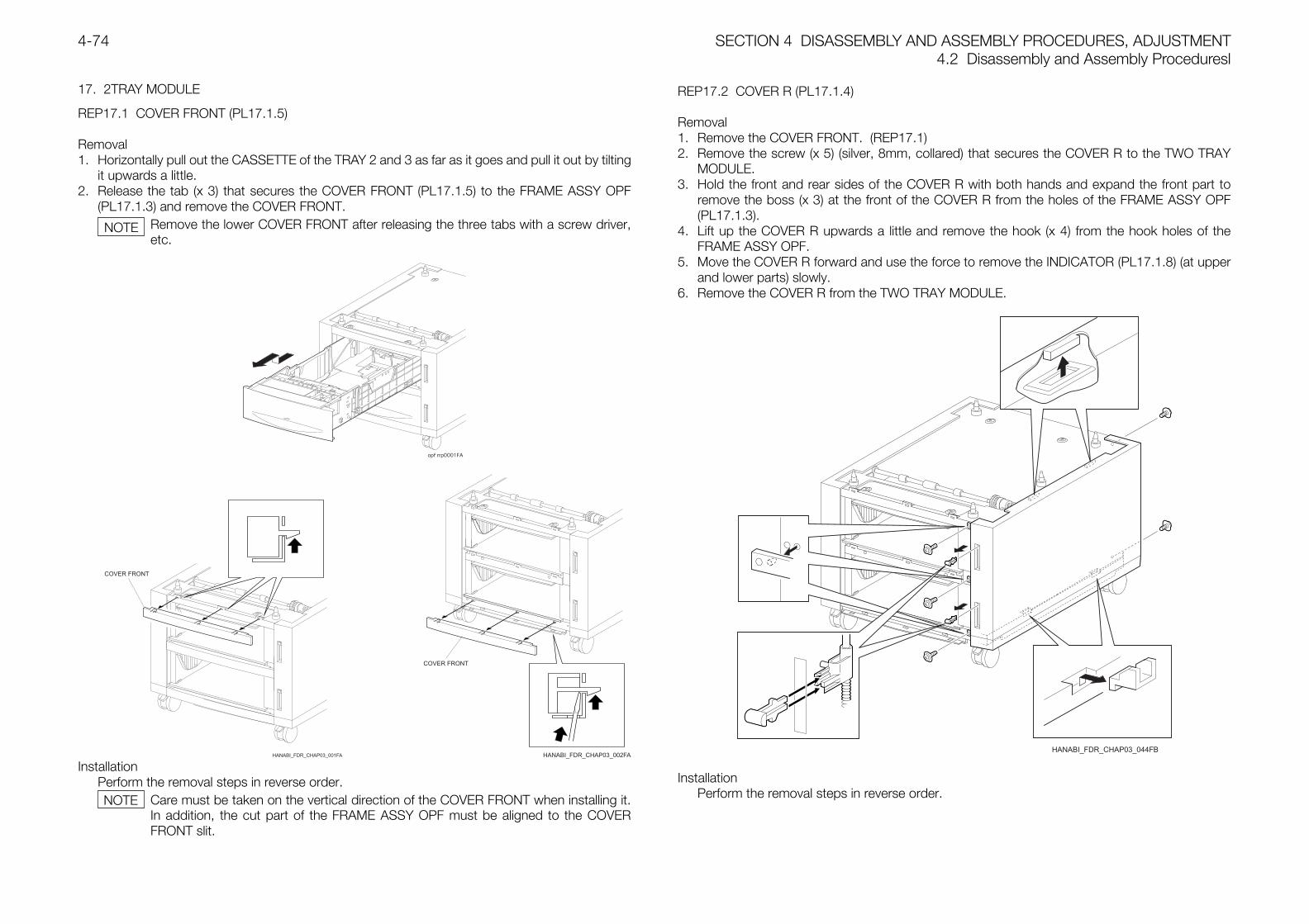
SECTION 4 DISASSEMBLY AND ASSEMBLY PROCEDURES, ADJUSTMENT4.2 Disassembly and Assembly Proceduresl
4-74
17. 2TRAY MODULE
REP17.1 COVER FRONT (PL17.1.5)
Removal1. Horizontally pull out the CASSETTE of the TRAY 2 and 3 as far as it goes and pull it out by tilting
it upwards a little.2. Release the tab (x 3) that secures the COVER FRONT (PL17.1.5) to the FRAME ASSY OPF
(PL17.1.3) and remove the COVER FRONT.Remove the lower COVER FRONT after releasing the three tabs with a screw driver,etc.
Installation
Perform the removal steps in reverse order.Care must be taken on the vertical direction of the COVER FRONT when installing it.In addition, the cut part of the FRAME ASSY OPF must be aligned to the COVERFRONT slit.
REP17.2 COVER R (PL17.1.4)
Removal1. Remove the COVER FRONT. (REP17.1)2. Remove the screw (x 5) (silver, 8mm, collared) that secures the COVER R to the TWO TRAY
MODULE.3. Hold the front and rear sides of the COVER R with both hands and expand the front part to
remove the boss (x 3) at the front of the COVER R from the holes of the FRAME ASSY OPF(PL17.1.3).
4. Lift up the COVER R upwards a little and remove the hook (x 4) from the hook holes of theFRAME ASSY OPF.
5. Move the COVER R forward and use the force to remove the INDICATOR (PL17.1.8) (at upperand lower parts) slowly.
6. Remove the COVER R from the TWO TRAY MODULE.
InstallationPerform the removal steps in reverse order.
NOTE
NOTE
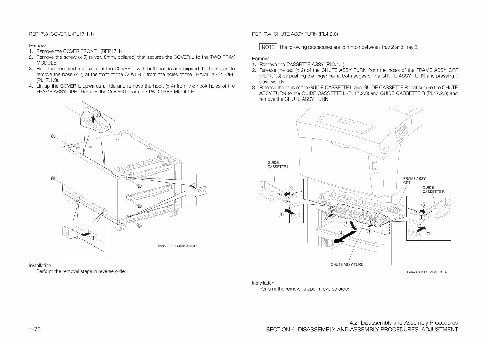
4.2 Disassembly and Assembly ProceduresSECTION 4 DISASSEMBLY AND ASSEMBLY PROCEDURES, ADJUSTMENT4-75
REP17.3 COVER L (PL17.1.1)
Removal1. Remove the COVER FRONT. (REP17.1)2. Remove the screw (x 5) (silver, 8mm, collared) that secures the COVER L to the TWO TRAY
MODULE.3. Hold the front and rear sides of the COVER L with both hands and expand the front part to
remove the boss (x 2) at the front of the COVER L from the holes of the FRAME ASSY OPF(PL17.1.3).
4. Lift up the COVER L upwards a little and remove the hook (x 4) from the hook holes of theFRAME ASSY OPF. Remove the COVER L from the TWO TRAY MODULE.
InstallationPerform the removal steps in reverse order.
REP17.4 CHUTE ASSY TURN (PL4.2.8)
The following procedures are common between Tray 2 and Tray 3.
Removal1. Remove the CASSETTE ASSY (PL2.1.4).2. Release the tab (x 2) of the CHUTE ASSY TURN from the holes of the FRAME ASSY OPF
(PL17.1.3) by pushing the finger nail at both edges of the CHUTE ASSY TURN and pressing itdownwards.
3. Release the tabs of the GUIDE CASSETTE L and GUIDE CASSETTE R that secure the CHUTEASSY TURN to the GUIDE CASSETTE L (PL17.2.3) and GUIDE CASSETTE R (PL17.2.6) andremove the CHUTE ASSY TURN.
1
12
3
3
4
4 4
HANABI_FDR_CHAP03_003FC
InstallationPerform the removal steps in reverse order.
NOTE
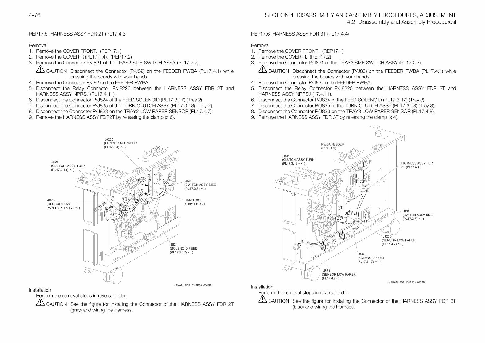
SECTION 4 DISASSEMBLY AND ASSEMBLY PROCEDURES, ADJUSTMENT4.2 Disassembly and Assembly Proceduresl
4-76
REP17.5 HARNESS ASSY FDR 2T (PL17.4.3)
Removal1. Remove the COVER FRONT. (REP17.1)2. Remove the COVER R (PL17.1.4). (REP17.2)3. Remove the Connector P/J821 of the TRAY2 SIZE SWITCH ASSY (PL17.2.7).
CAUTION Disconnect the Connector (P/J82) on the FEEDER PWBA (PL17.4.1) whilepressing the boards with your hands.
4. Remove the Connector P/J82 on the FEEDER PWBA.5. Disconnect the Relay Connector P/J8220 between the HARNESS ASSY FDR 2T and
HARNESS ASSY NPRSJ (PL17.4.11).6. Disconnect the Connector P/J824 of the FEED SOLENOID (PL17.3.17) (Tray 2).7. Disconnect the Connector P/J825 of the TURN CLUTCH ASSY (PL17.3.18) (Tray 2).8. Disconnect the Connector P/J823 on the TRAY2 LOW PAPER SENSOR (PL17.4.7).9. Remove the HARNESS ASSY FDR2T by releasing the clamp (x 6).
InstallationPerform the removal steps in reverse order.
CAUTION See the figure for installing the Connector of the HARNESS ASSY FDR 2T(gray) and wiring the Harness.
REP17.6 HARNESS ASSY FDR 3T (PL17.4.4)
Removal1. Remove the COVER FRONT. (REP17.1)2. Remove the COVER R. (REP17.2)3. Remove the Connector P/J821 of the TRAY3 SIZE SWITCH ASSY (PL17.2.7).
CAUTION Disconnect the Connector (P/J83) on the FEEDER PWBA (PL17.4.1) whilepressing the boards with your hands.
4. Remove the Connector P/J83 on the FEEDER PWBA.5. Disconnect the Relay Connector P/J8220 between the HARNESS ASSY FDR 3T and
HARNESS ASSY NPRSJ (17.4.11).6. Disconnect the Connector P/J834 of the FEED SOLENOID (PL17.3.17) (Tray 3).7. Disconnect the Connector P/J835 of the TURN CLUTCH ASSY (PL17.3.18) (Tray 3).8. Disconnect the Connector P/J833 on the TRAY3 LOW PAPER SENSOR (PL17.4.8).9. Remove the HARNESS ASSY FDR 3T by releasing the clamp (x 4).
InstallationPerform the removal steps in reverse order.
CAUTION See the figure for installing the Connector of the HARNESS ASSY FDR 3T(blue) and wiring the Harness.
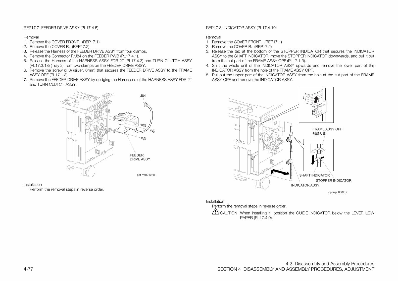
4.2 Disassembly and Assembly ProceduresSECTION 4 DISASSEMBLY AND ASSEMBLY PROCEDURES, ADJUSTMENT4-77
REP17.7 FEEDER DRIVE ASSY (PL17.4.5)
Removal1. Remove the COVER FRONT. (REP17.1)2. Remove the COVER R. (REP17.2)3. Release the Harness of the FEEDER DRIVE ASSY from four clamps.4. Remove the Connector P/J84 on the FEEDER PWB (PL17.4.1).5. Release the Harness of the HARNESS ASSY FDR 2T (PL17.4.3) and TURN CLUTCH ASSY
(PL17.3.18) (Tray 2) from two clamps on the FEEDER DRIVE ASSY.6. Remove the screw (x 3) (silver, 6mm) that secures the FEEDER DRIVE ASSY to the FRAME
ASSY OPF (PL17.1.3).7. Remove the FEEDER DRIVE ASSY by dodging the Harnesses of the HARNESS ASSY FDR 2T
and TURN CLUTCH ASSY.
opf rrp0010FB
InstallationPerform the removal steps in reverse order.
REP17.8 INDICATOR ASSY (PL17.4.10)
Removal1. Remove the COVER FRONT. (REP17.1)2. Remove the COVER R. (REP17.2)3. Release the tab at the bottom of the STOPPER INDICATOR that secures the INDICATOR
ASSY to the SHAFT INDICATOR, move the STOPPER INDICATOR downwards, and pull it outfrom the cut part of the FRAME ASSY OPF (PL17.1.3).
4. Shift the whole unit of the INDICATOR ASSY upwards and remove the lower part of theINDICATOR ASSY from the hole of the FRAME ASSY OPF.
5. Pull out the upper part of the INDICATOR ASSY from the hole at the cut part of the FRAMEASSY OPF and remove the INDICATOR ASSY.
opf rrp0008FB
SHAFT INDICATOR
InstallationPerform the removal steps in reverse order.
CAUTION When installing it, position the GUIDE INDICATOR below the LEVER LOWPAPER (PL17.4.9).
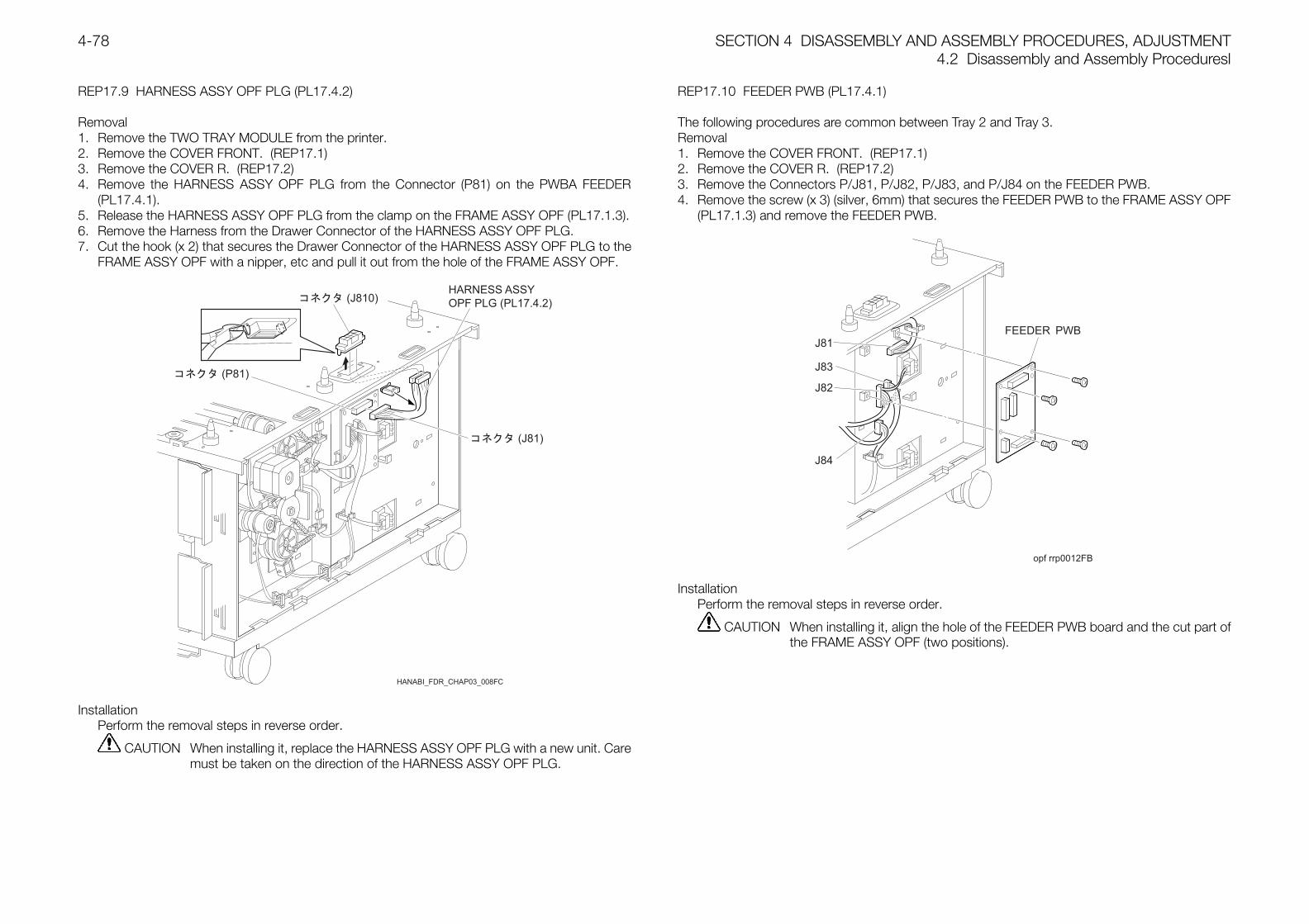
SECTION 4 DISASSEMBLY AND ASSEMBLY PROCEDURES, ADJUSTMENT4.2 Disassembly and Assembly Proceduresl
4-78
REP17.9 HARNESS ASSY OPF PLG (PL17.4.2)
Removal1. Remove the TWO TRAY MODULE from the printer.2. Remove the COVER FRONT. (REP17.1)3. Remove the COVER R. (REP17.2)4. Remove the HARNESS ASSY OPF PLG from the Connector (P81) on the PWBA FEEDER
(PL17.4.1).5. Release the HARNESS ASSY OPF PLG from the clamp on the FRAME ASSY OPF (PL17.1.3).6. Remove the Harness from the Drawer Connector of the HARNESS ASSY OPF PLG.7. Cut the hook (x 2) that secures the Drawer Connector of the HARNESS ASSY OPF PLG to the
FRAME ASSY OPF with a nipper, etc and pull it out from the hole of the FRAME ASSY OPF.
InstallationPerform the removal steps in reverse order.
CAUTION When installing it, replace the HARNESS ASSY OPF PLG with a new unit. Caremust be taken on the direction of the HARNESS ASSY OPF PLG.
REP17.10 FEEDER PWB (PL17.4.1)
The following procedures are common between Tray 2 and Tray 3.Removal1. Remove the COVER FRONT. (REP17.1)2. Remove the COVER R. (REP17.2)3. Remove the Connectors P/J81, P/J82, P/J83, and P/J84 on the FEEDER PWB.4. Remove the screw (x 3) (silver, 6mm) that secures the FEEDER PWB to the FRAME ASSY OPF
(PL17.1.3) and remove the FEEDER PWB.
opf rrp0012FB
InstallationPerform the removal steps in reverse order.
CAUTION When installing it, align the hole of the FEEDER PWB board and the cut part ofthe FRAME ASSY OPF (two positions).
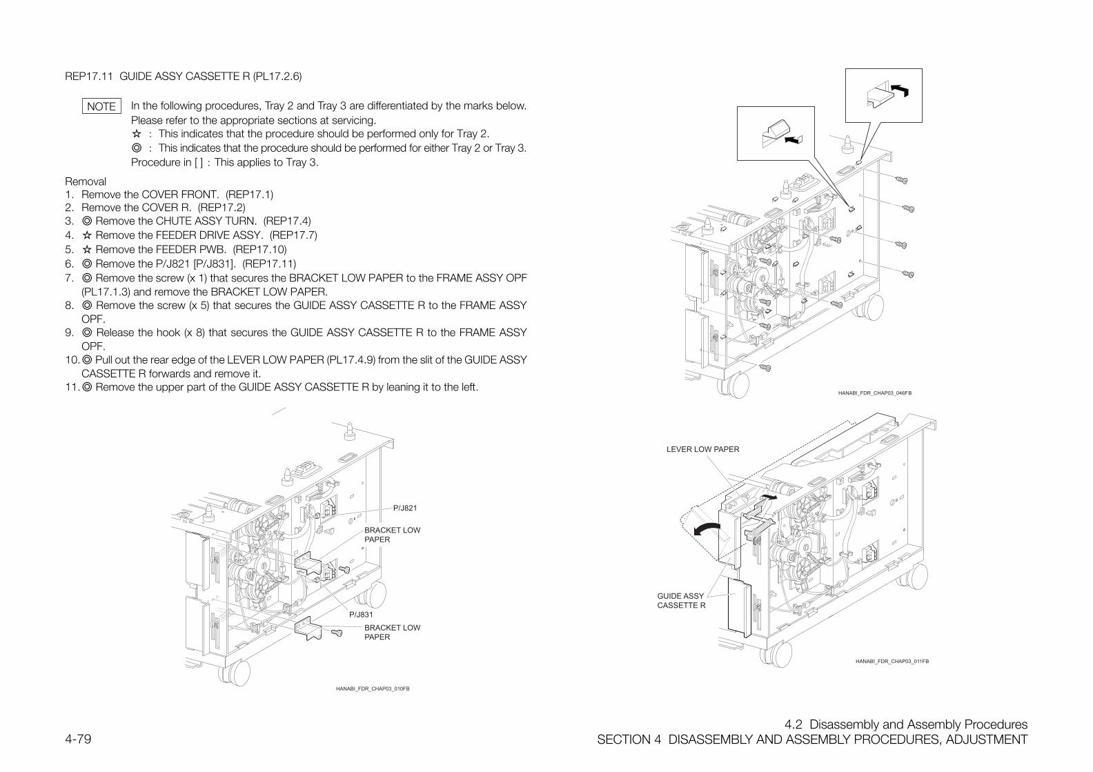
4.2 Disassembly and Assembly ProceduresSECTION 4 DISASSEMBLY AND ASSEMBLY PROCEDURES, ADJUSTMENT4-79
REP17.11 GUIDE ASSY CASSETTE R (PL17.2.6)
In the following procedures, Tray 2 and Tray 3 are differentiated by the marks below.Please refer to the appropriate sections at servicing. : This indicates that the procedure should be performed only for Tray 2. : This indicates that the procedure should be performed for either Tray 2 or Tray 3.Procedure in [ ] : This applies to Tray 3.
Removal1. Remove the COVER FRONT. (REP17.1)2. Remove the COVER R. (REP17.2)3. Remove the CHUTE ASSY TURN. (REP17.4)4. Remove the FEEDER DRIVE ASSY. (REP17.7)5. Remove the FEEDER PWB. (REP17.10)6. Remove the P/J821 [P/J831]. (REP17.11)7. Remove the screw (x 1) that secures the BRACKET LOW PAPER to the FRAME ASSY OPF
(PL17.1.3) and remove the BRACKET LOW PAPER.8. Remove the screw (x 5) that secures the GUIDE ASSY CASSETTE R to the FRAME ASSY
OPF.9. Release the hook (x 8) that secures the GUIDE ASSY CASSETTE R to the FRAME ASSY
OPF.10. Pull out the rear edge of the LEVER LOW PAPER (PL17.4.9) from the slit of the GUIDE ASSY
CASSETTE R forwards and remove it.11. Remove the upper part of the GUIDE ASSY CASSETTE R by leaning it to the left.
NOTE
SECTION 4 DISASSEMBLY AND ASSEMBLY PROCEDURES, ADJUSTMENT4.2 Disassembly and Assembly Proceduresl
4-80
Installation1. Place the GUIDE ASSY CASSETTE R near to the installation position with its upper part
leaning to the left.2. Twist and let the rear edge of the LEVER LOW PAPER through the slit of the GUIDE ASSY
CASSETTE R. 3. In parallel with letting the front edge of the LEVER LOW PAPER through the opening of the
FRAME ASSY OPF, shift the upper part of the GUIDE ASSY CASSETTE R to the right to placeit at the installation position.
4. Press the GUIDE ASSY CASSETTE R to the right and secure it to the FRAME ASSY OPFwith 8 hooks.
5. Secure the GUIDE ASSY CASSETTE R to the FRAME ASSY OPF with five screws (gold,tapped, 8mm).
6. Position the shaft of the LEVER LOW PAPER at the fallen part of the GUIDE ASSYCASSETTE R and the hole of the BRACKET LOW PAPER and place it with the positioning holeof the BRACKET ASSY LOW PAPER aligned to the positioning punch of the FRAME ASSYOPF.
7. Secure the BRACKET LOW PAPER to the FRAME ASSY OPF with one screw (silver, 6mm).8. Install the FEEDER PWB. (REP17.10)9. Install the FEEDER DRIVE ASSY. (REP17.7)10. Install the CHUTE ASSY TURN. (REP17.4)11. Install the COVER R. (REP17.2)12. Install the COVER FRONT. (REP17.1)
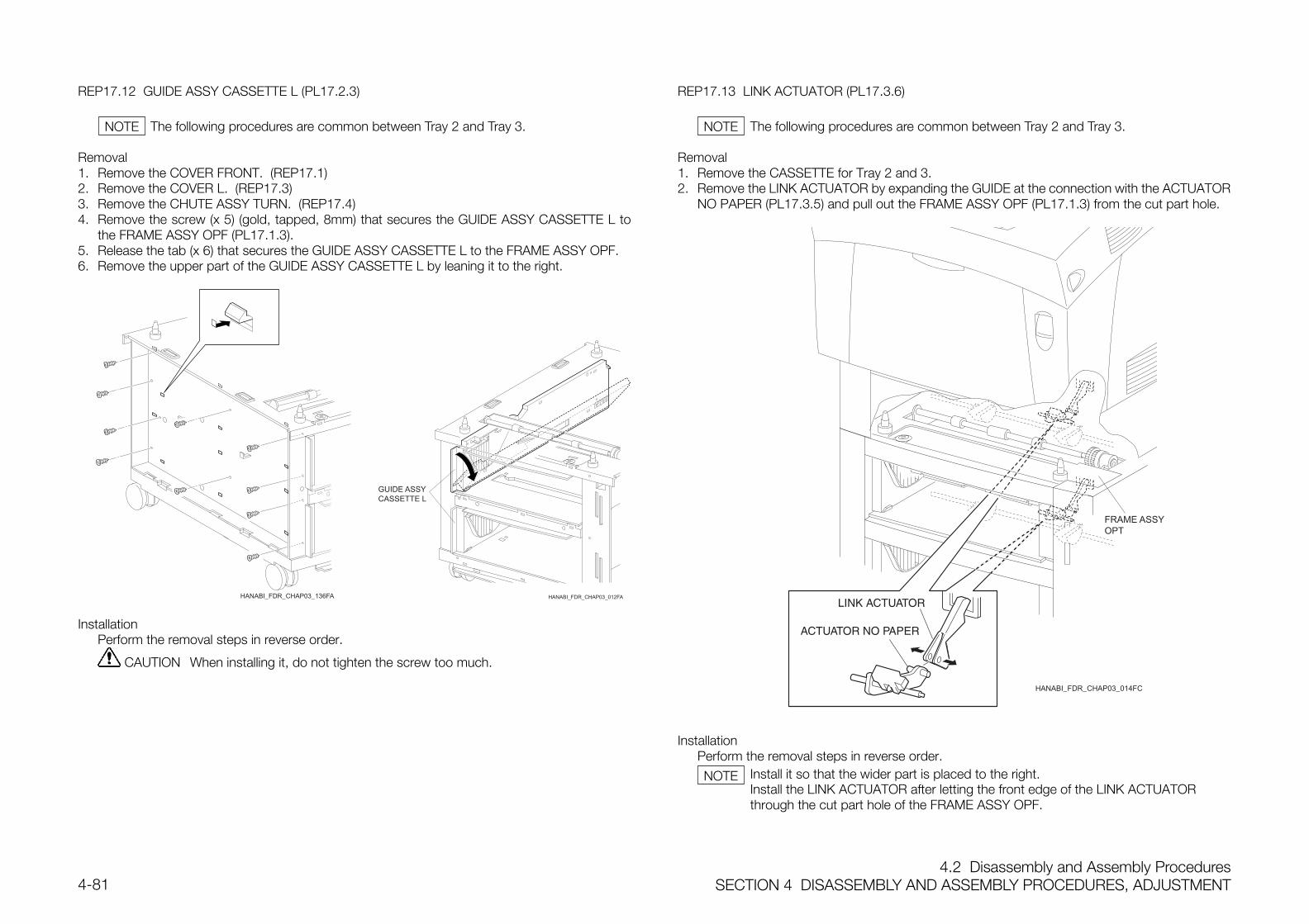
4.2 Disassembly and Assembly ProceduresSECTION 4 DISASSEMBLY AND ASSEMBLY PROCEDURES, ADJUSTMENT4-81
REP17.12 GUIDE ASSY CASSETTE L (PL17.2.3)
The following procedures are common between Tray 2 and Tray 3.
Removal1. Remove the COVER FRONT. (REP17.1)2. Remove the COVER L. (REP17.3)3. Remove the CHUTE ASSY TURN. (REP17.4)4. Remove the screw (x 5) (gold, tapped, 8mm) that secures the GUIDE ASSY CASSETTE L to
the FRAME ASSY OPF (PL17.1.3).5. Release the tab (x 6) that secures the GUIDE ASSY CASSETTE L to the FRAME ASSY OPF.6. Remove the upper part of the GUIDE ASSY CASSETTE L by leaning it to the right.
HANABI_FDR_CHAP03_136FA
InstallationPerform the removal steps in reverse order.
CAUTION When installing it, do not tighten the screw too much.
REP17.13 LINK ACTUATOR (PL17.3.6)
The following procedures are common between Tray 2 and Tray 3.
Removal1. Remove the CASSETTE for Tray 2 and 3.2. Remove the LINK ACTUATOR by expanding the GUIDE at the connection with the ACTUATOR
NO PAPER (PL17.3.5) and pull out the FRAME ASSY OPF (PL17.1.3) from the cut part hole.
HANABI_FDR_CHAP03_014FC
InstallationPerform the removal steps in reverse order.
Install it so that the wider part is placed to the right.Install the LINK ACTUATOR after letting the front edge of the LINK ACTUATORthrough the cut part hole of the FRAME ASSY OPF.
NOTE NOTE
NOTE
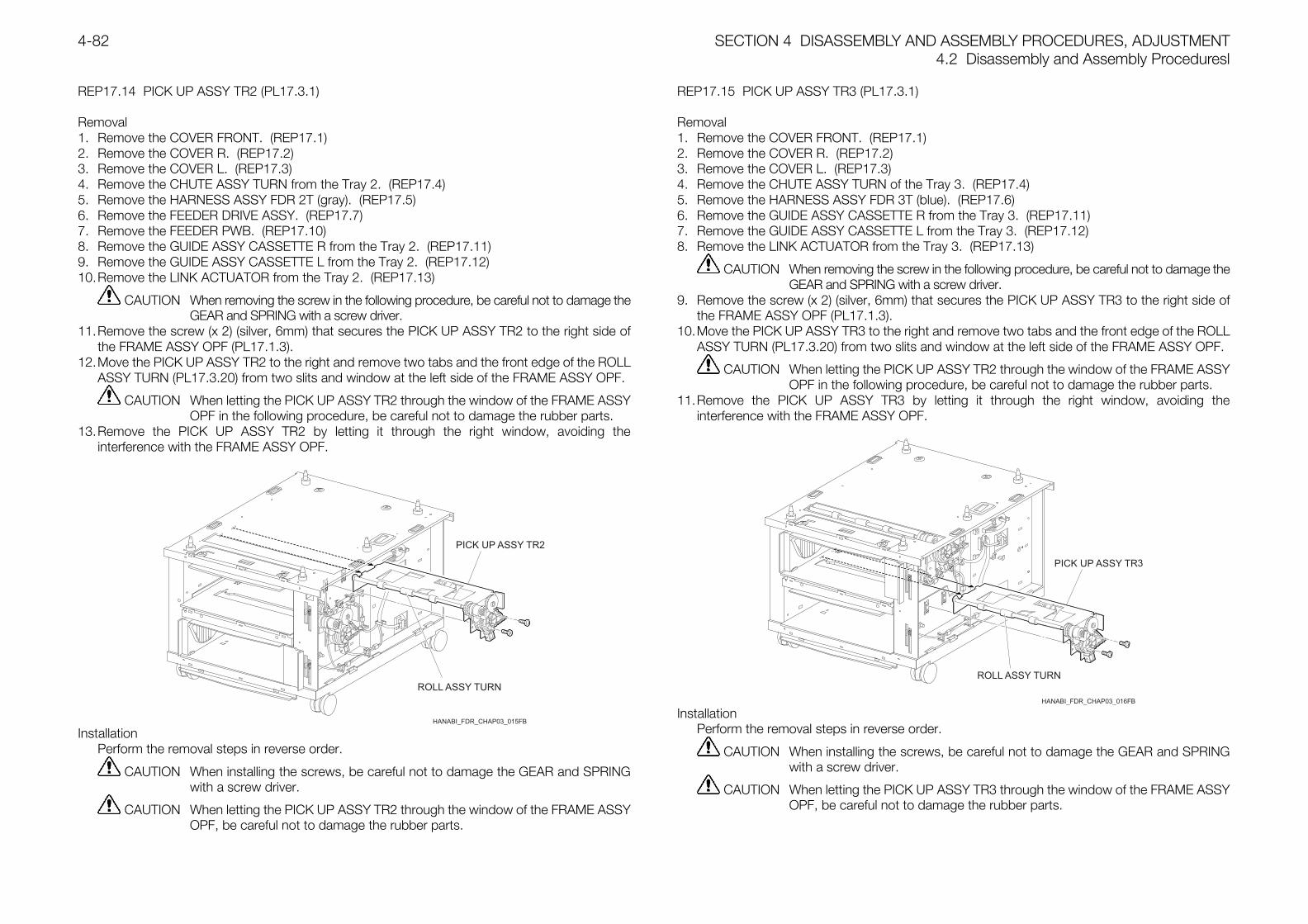
SECTION 4 DISASSEMBLY AND ASSEMBLY PROCEDURES, ADJUSTMENT4.2 Disassembly and Assembly Proceduresl
4-82
REP17.14 PICK UP ASSY TR2 (PL17.3.1)
Removal1. Remove the COVER FRONT. (REP17.1)2. Remove the COVER R. (REP17.2)3. Remove the COVER L. (REP17.3)4. Remove the CHUTE ASSY TURN from the Tray 2. (REP17.4)5. Remove the HARNESS ASSY FDR 2T (gray). (REP17.5)6. Remove the FEEDER DRIVE ASSY. (REP17.7)7. Remove the FEEDER PWB. (REP17.10)8. Remove the GUIDE ASSY CASSETTE R from the Tray 2. (REP17.11)9. Remove the GUIDE ASSY CASSETTE L from the Tray 2. (REP17.12)10.Remove the LINK ACTUATOR from the Tray 2. (REP17.13)
CAUTION When removing the screw in the following procedure, be careful not to damage theGEAR and SPRING with a screw driver.
11.Remove the screw (x 2) (silver, 6mm) that secures the PICK UP ASSY TR2 to the right side ofthe FRAME ASSY OPF (PL17.1.3).
12.Move the PICK UP ASSY TR2 to the right and remove two tabs and the front edge of the ROLLASSY TURN (PL17.3.20) from two slits and window at the left side of the FRAME ASSY OPF.
CAUTION When letting the PICK UP ASSY TR2 through the window of the FRAME ASSYOPF in the following procedure, be careful not to damage the rubber parts.
13.Remove the PICK UP ASSY TR2 by letting it through the right window, avoiding theinterference with the FRAME ASSY OPF.
InstallationPerform the removal steps in reverse order.
CAUTION When installing the screws, be careful not to damage the GEAR and SPRINGwith a screw driver.
CAUTION When letting the PICK UP ASSY TR2 through the window of the FRAME ASSYOPF, be careful not to damage the rubber parts.
REP17.15 PICK UP ASSY TR3 (PL17.3.1)
Removal1. Remove the COVER FRONT. (REP17.1)2. Remove the COVER R. (REP17.2)3. Remove the COVER L. (REP17.3)4. Remove the CHUTE ASSY TURN of the Tray 3. (REP17.4)5. Remove the HARNESS ASSY FDR 3T (blue). (REP17.6)6. Remove the GUIDE ASSY CASSETTE R from the Tray 3. (REP17.11)7. Remove the GUIDE ASSY CASSETTE L from the Tray 3. (REP17.12)8. Remove the LINK ACTUATOR from the Tray 3. (REP17.13)
CAUTION When removing the screw in the following procedure, be careful not to damage theGEAR and SPRING with a screw driver.
9. Remove the screw (x 2) (silver, 6mm) that secures the PICK UP ASSY TR3 to the right side ofthe FRAME ASSY OPF (PL17.1.3).
10.Move the PICK UP ASSY TR3 to the right and remove two tabs and the front edge of the ROLLASSY TURN (PL17.3.20) from two slits and window at the left side of the FRAME ASSY OPF.
CAUTION When letting the PICK UP ASSY TR2 through the window of the FRAME ASSYOPF in the following procedure, be careful not to damage the rubber parts.
11.Remove the PICK UP ASSY TR3 by letting it through the right window, avoiding theinterference with the FRAME ASSY OPF.
InstallationPerform the removal steps in reverse order.
CAUTION When installing the screws, be careful not to damage the GEAR and SPRINGwith a screw driver.
CAUTION When letting the PICK UP ASSY TR3 through the window of the FRAME ASSYOPF, be careful not to damage the rubber parts.
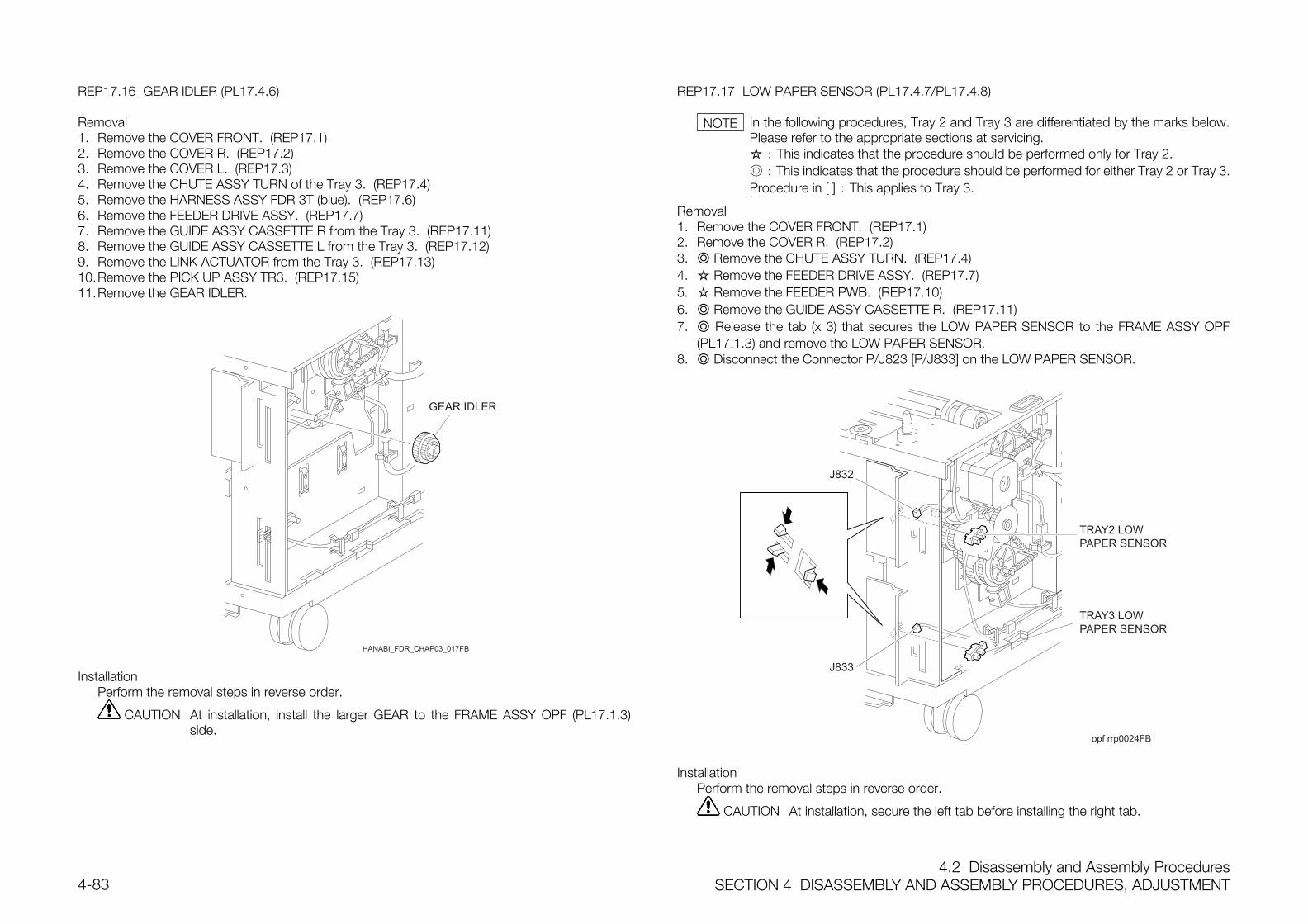
4.2 Disassembly and Assembly ProceduresSECTION 4 DISASSEMBLY AND ASSEMBLY PROCEDURES, ADJUSTMENT4-83
REP17.16 GEAR IDLER (PL17.4.6)
Removal1. Remove the COVER FRONT. (REP17.1)2. Remove the COVER R. (REP17.2)3. Remove the COVER L. (REP17.3)4. Remove the CHUTE ASSY TURN of the Tray 3. (REP17.4)5. Remove the HARNESS ASSY FDR 3T (blue). (REP17.6)6. Remove the FEEDER DRIVE ASSY. (REP17.7)7. Remove the GUIDE ASSY CASSETTE R from the Tray 3. (REP17.11)8. Remove the GUIDE ASSY CASSETTE L from the Tray 3. (REP17.12)9. Remove the LINK ACTUATOR from the Tray 3. (REP17.13)10.Remove the PICK UP ASSY TR3. (REP17.15)11.Remove the GEAR IDLER.
InstallationPerform the removal steps in reverse order.
CAUTION At installation, install the larger GEAR to the FRAME ASSY OPF (PL17.1.3)side.
REP17.17 LOW PAPER SENSOR (PL17.4.7/PL17.4.8)
In the following procedures, Tray 2 and Tray 3 are differentiated by the marks below.Please refer to the appropriate sections at servicing. : This indicates that the procedure should be performed only for Tray 2. : This indicates that the procedure should be performed for either Tray 2 or Tray 3.Procedure in [ ] : This applies to Tray 3.
Removal1. Remove the COVER FRONT. (REP17.1)2. Remove the COVER R. (REP17.2)3. Remove the CHUTE ASSY TURN. (REP17.4)4. Remove the FEEDER DRIVE ASSY. (REP17.7)5. Remove the FEEDER PWB. (REP17.10)6. Remove the GUIDE ASSY CASSETTE R. (REP17.11)7. Release the tab (x 3) that secures the LOW PAPER SENSOR to the FRAME ASSY OPF
(PL17.1.3) and remove the LOW PAPER SENSOR.8. Disconnect the Connector P/J823 [P/J833] on the LOW PAPER SENSOR.
opf rrp0024FB
TRAY2 LOWPAPER SENSOR
TRAY3 LOWPAPER SENSOR
InstallationPerform the removal steps in reverse order.
CAUTION At installation, secure the left tab before installing the right tab.
NOTE
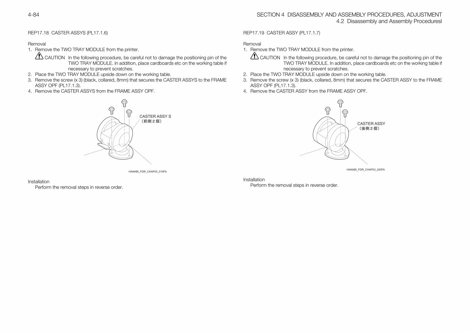
SECTION 4 DISASSEMBLY AND ASSEMBLY PROCEDURES, ADJUSTMENT4.2 Disassembly and Assembly Proceduresl
4-84
REP17.18 CASTER ASSYS (PL17.1.6)
Removal1. Remove the TWO TRAY MODULE from the printer.
CAUTION In the following procedure, be careful not to damage the positioning pin of theTWO TRAY MODULE. In addition, place cardboards etc on the working table ifnecessary to prevent scratches.
2. Place the TWO TRAY MODULE upside down on the working table.3. Remove the screw (x 3) (black, collared, 8mm) that secures the CASTER ASSYS to the FRAME
ASSY OPF (PL17.1.3).4. Remove the CASTER ASSYS from the FRAME ASSY OPF.
InstallationPerform the removal steps in reverse order.
REP17.19 CASTER ASSY (PL17.1.7)
Removal1. Remove the TWO TRAY MODULE from the printer.
CAUTION In the following procedure, be careful not to damage the positioning pin of theTWO TRAY MODULE. In addition, place cardboards etc on the working table ifnecessary to prevent scratches.
2. Place the TWO TRAY MODULE upside down on the working table.3. Remove the screw (x 3) (black, collared, 8mm) that secures the CASTER ASSY to the FRAME
ASSY OPF (PL17.1.3).4. Remove the CASTER ASSY from the FRAME ASSY OPF.
InstallationPerform the removal steps in reverse order.
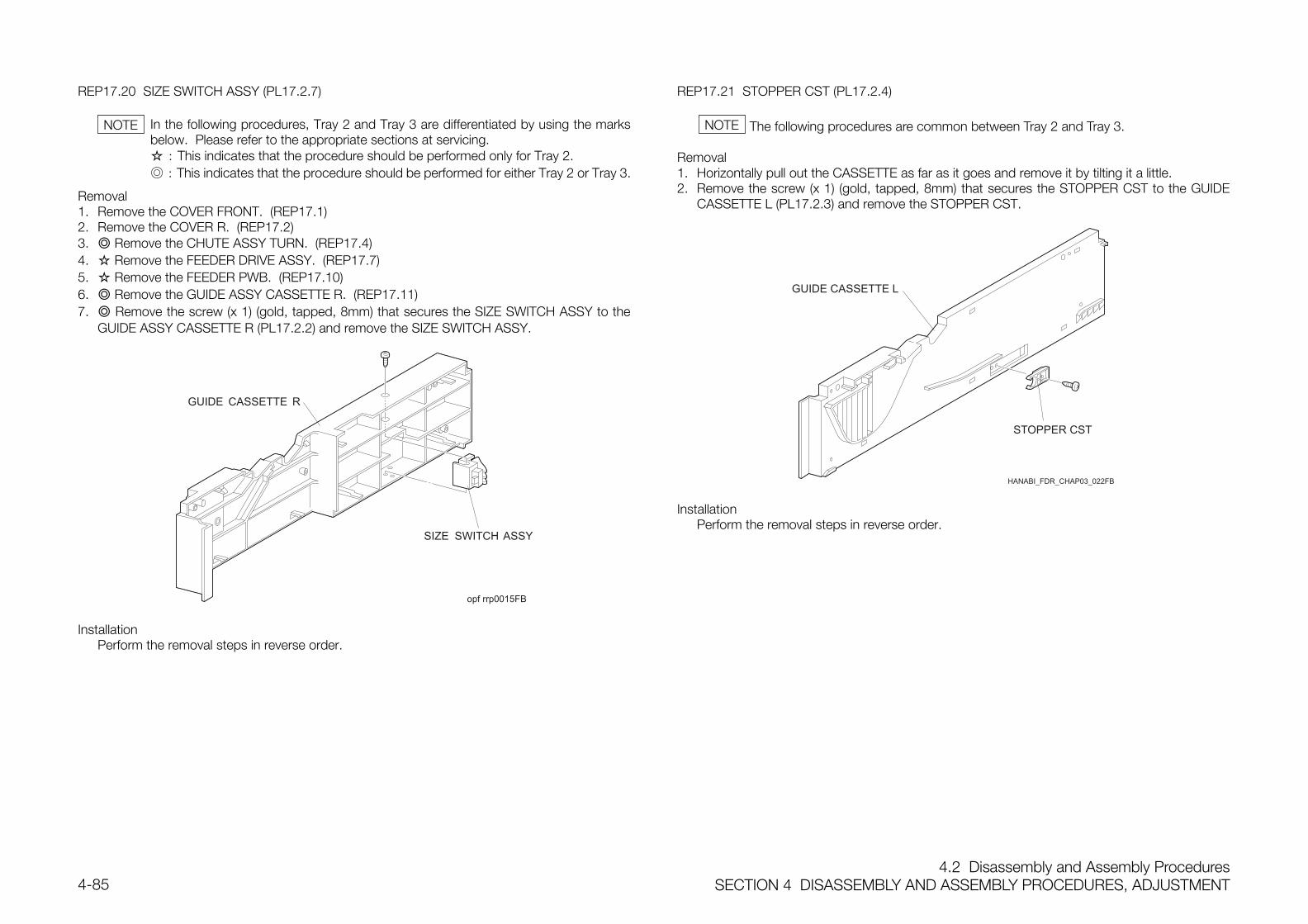
4.2 Disassembly and Assembly ProceduresSECTION 4 DISASSEMBLY AND ASSEMBLY PROCEDURES, ADJUSTMENT4-85
REP17.20 SIZE SWITCH ASSY (PL17.2.7)
In the following procedures, Tray 2 and Tray 3 are differentiated by using the marksbelow. Please refer to the appropriate sections at servicing. : This indicates that the procedure should be performed only for Tray 2. : This indicates that the procedure should be performed for either Tray 2 or Tray 3.
Removal1. Remove the COVER FRONT. (REP17.1)2. Remove the COVER R. (REP17.2)3. Remove the CHUTE ASSY TURN. (REP17.4)4. Remove the FEEDER DRIVE ASSY. (REP17.7)5. Remove the FEEDER PWB. (REP17.10)6. Remove the GUIDE ASSY CASSETTE R. (REP17.11)7. Remove the screw (x 1) (gold, tapped, 8mm) that secures the SIZE SWITCH ASSY to the
GUIDE ASSY CASSETTE R (PL17.2.2) and remove the SIZE SWITCH ASSY.
opf rrp0015FB
InstallationPerform the removal steps in reverse order.
REP17.21 STOPPER CST (PL17.2.4)
The following procedures are common between Tray 2 and Tray 3.
Removal1. Horizontally pull out the CASSETTE as far as it goes and remove it by tilting it a little.2. Remove the screw (x 1) (gold, tapped, 8mm) that secures the STOPPER CST to the GUIDE
CASSETTE L (PL17.2.3) and remove the STOPPER CST.
InstallationPerform the removal steps in reverse order.
NOTE NOTE
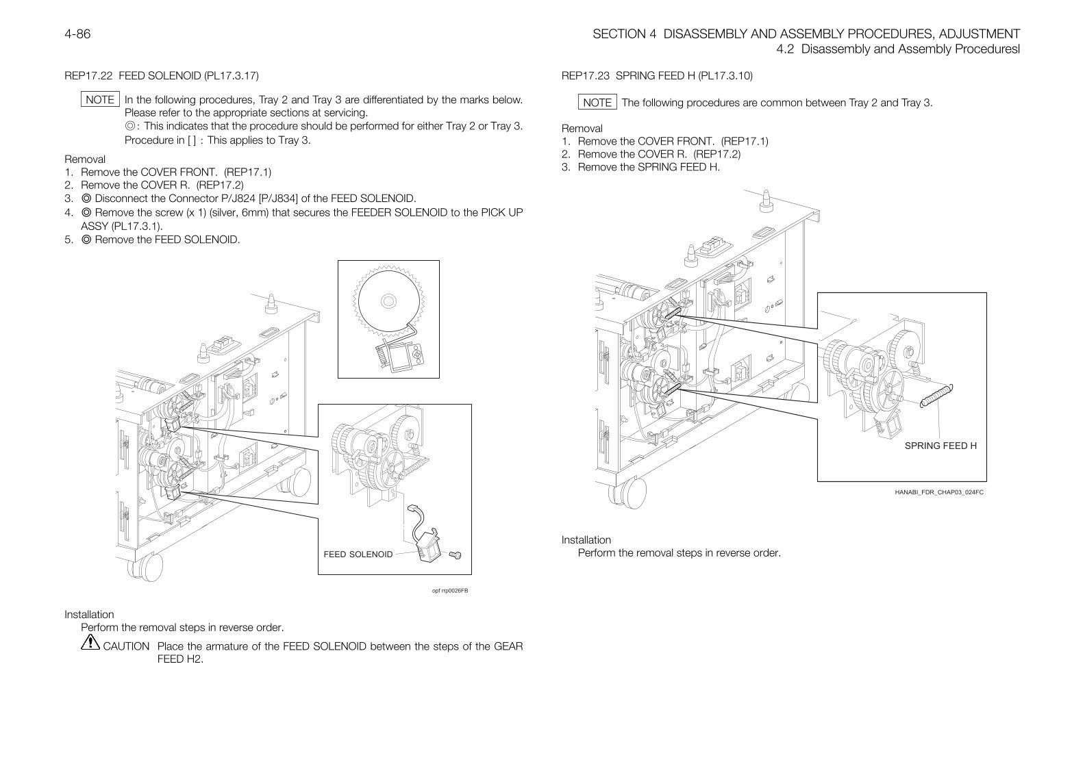
SECTION 4 DISASSEMBLY AND ASSEMBLY PROCEDURES, ADJUSTMENT4.2 Disassembly and Assembly Proceduresl
4-86
REP17.22 FEED SOLENOID (PL17.3.17)
In the following procedures, Tray 2 and Tray 3 are differentiated by the marks below.Please refer to the appropriate sections at servicing.: This indicates that the procedure should be performed for either Tray 2 or Tray 3.Procedure in [ ] : This applies to Tray 3.
Removal1. Remove the COVER FRONT. (REP17.1)2. Remove the COVER R. (REP17.2)3. Disconnect the Connector P/J824 [P/J834] of the FEED SOLENOID.4. Remove the screw (x 1) (silver, 6mm) that secures the FEEDER SOLENOID to the PICK UP
ASSY (PL17.3.1).5. Remove the FEED SOLENOID.
opf rrp0026FB
InstallationPerform the removal steps in reverse order.
CAUTION Place the armature of the FEED SOLENOID between the steps of the GEARFEED H2.
REP17.23 SPRING FEED H (PL17.3.10)
The following procedures are common between Tray 2 and Tray 3.
Removal1. Remove the COVER FRONT. (REP17.1)2. Remove the COVER R. (REP17.2)3. Remove the SPRING FEED H.
HANABI_FDR_CHAP03_024FC
InstallationPerform the removal steps in reverse order.
NOTE NOTE
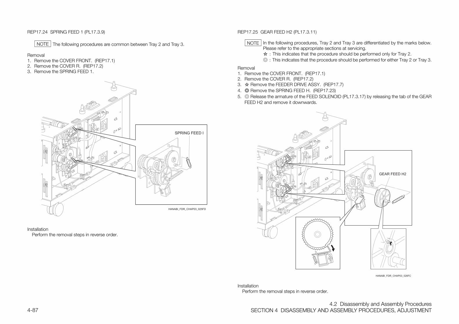
4.2 Disassembly and Assembly ProceduresSECTION 4 DISASSEMBLY AND ASSEMBLY PROCEDURES, ADJUSTMENT4-87
REP17.24 SPRING FEED 1 (PL17.3.9)
The following procedures are common between Tray 2 and Tray 3.
Removal1. Remove the COVER FRONT. (REP17.1)2. Remove the COVER R. (REP17.2)3. Remove the SPRING FEED 1.
HANABI_FDR_CHAP03_025FD
InstallationPerform the removal steps in reverse order.
REP17.25 GEAR FEED H2 (PL17.3.11)
In the following procedures, Tray 2 and Tray 3 are differentiated by the marks below.Please refer to the appropriate sections at servicing. : This indicates that the procedure should be performed only for Tray 2. : This indicates that the procedure should be performed for either Tray 2 or Tray 3.
Removal1. Remove the COVER FRONT. (REP17.1)2. Remove the COVER R. (REP17.2)3. Remove the FEEDER DRIVE ASSY. (REP17.7)4. Remove the SPRING FEED H. (REP17.23)5. Release the armature of the FEED SOLENOID (PL17.3.17) by releasing the tab of the GEAR
FEED H2 and remove it downwards.
HANABI_FDR_CHAP03_026FC
InstallationPerform the removal steps in reverse order.
NOTE NOTE
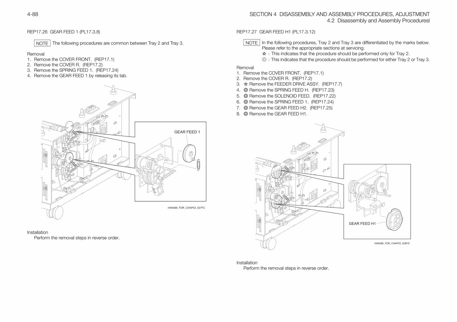
SECTION 4 DISASSEMBLY AND ASSEMBLY PROCEDURES, ADJUSTMENT4.2 Disassembly and Assembly Proceduresl
4-88
REP17.26 GEAR FEED 1 (PL17.3.8)
The following procedures are common between Tray 2 and Tray 3.
Removal1. Remove the COVER FRONT. (REP17.1)2. Remove the COVER R. (REP17.2)3. Remove the SPRING FEED 1. (REP17.24)4. Remove the GEAR FEED 1 by releasing its tab.
HANABI_FDR_CHAP03_027FC
InstallationPerform the removal steps in reverse order.
REP17.27 GEAR FEED H1 (PL17.3.12)
In the following procedures, Tray 2 and Tray 3 are differentiated by the marks below.Please refer to the appropriate sections at servicing. : This indicates that the procedure should be performed only for Tray 2. : This indicates that the procedure should be performed for either Tray 2 or Tray 3.
Removal1. Remove the COVER FRONT. (REP17.1)2. Remove the COVER R. (REP17.2)3. Remove the FEEDER DRIVE ASSY. (REP17.7)4. Remove the SPRING FEED H. (REP17.23)5. Remove the SOLENOID FEED. (REP17.22)6. Remove the SPRING FEED 1. (REP17.24)7. Remove the GEAR FEED H2. (REP17.25)8. Remove the GEAR FEED H1.
HANABI_FDR_CHAP03_028FD
InstallationPerform the removal steps in reverse order.
NOTE NOTE
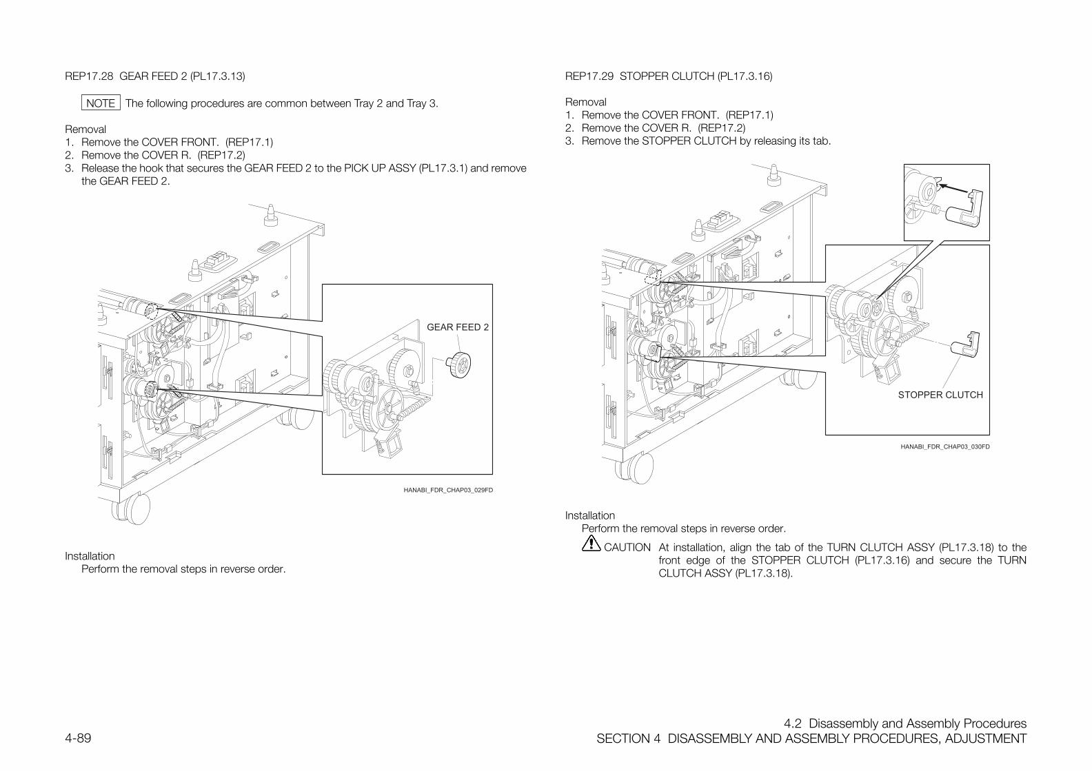
4.2 Disassembly and Assembly ProceduresSECTION 4 DISASSEMBLY AND ASSEMBLY PROCEDURES, ADJUSTMENT4-89
REP17.28 GEAR FEED 2 (PL17.3.13)
The following procedures are common between Tray 2 and Tray 3.
Removal1. Remove the COVER FRONT. (REP17.1)2. Remove the COVER R. (REP17.2)3. Release the hook that secures the GEAR FEED 2 to the PICK UP ASSY (PL17.3.1) and remove
the GEAR FEED 2.
HANABI_FDR_CHAP03_029FD
InstallationPerform the removal steps in reverse order.
REP17.29 STOPPER CLUTCH (PL17.3.16)
Removal1. Remove the COVER FRONT. (REP17.1)2. Remove the COVER R. (REP17.2)3. Remove the STOPPER CLUTCH by releasing its tab.
HANABI_FDR_CHAP03_030FD
InstallationPerform the removal steps in reverse order.
CAUTION At installation, align the tab of the TURN CLUTCH ASSY (PL17.3.18) to thefront edge of the STOPPER CLUTCH (PL17.3.16) and secure the TURNCLUTCH ASSY (PL17.3.18).
NOTE
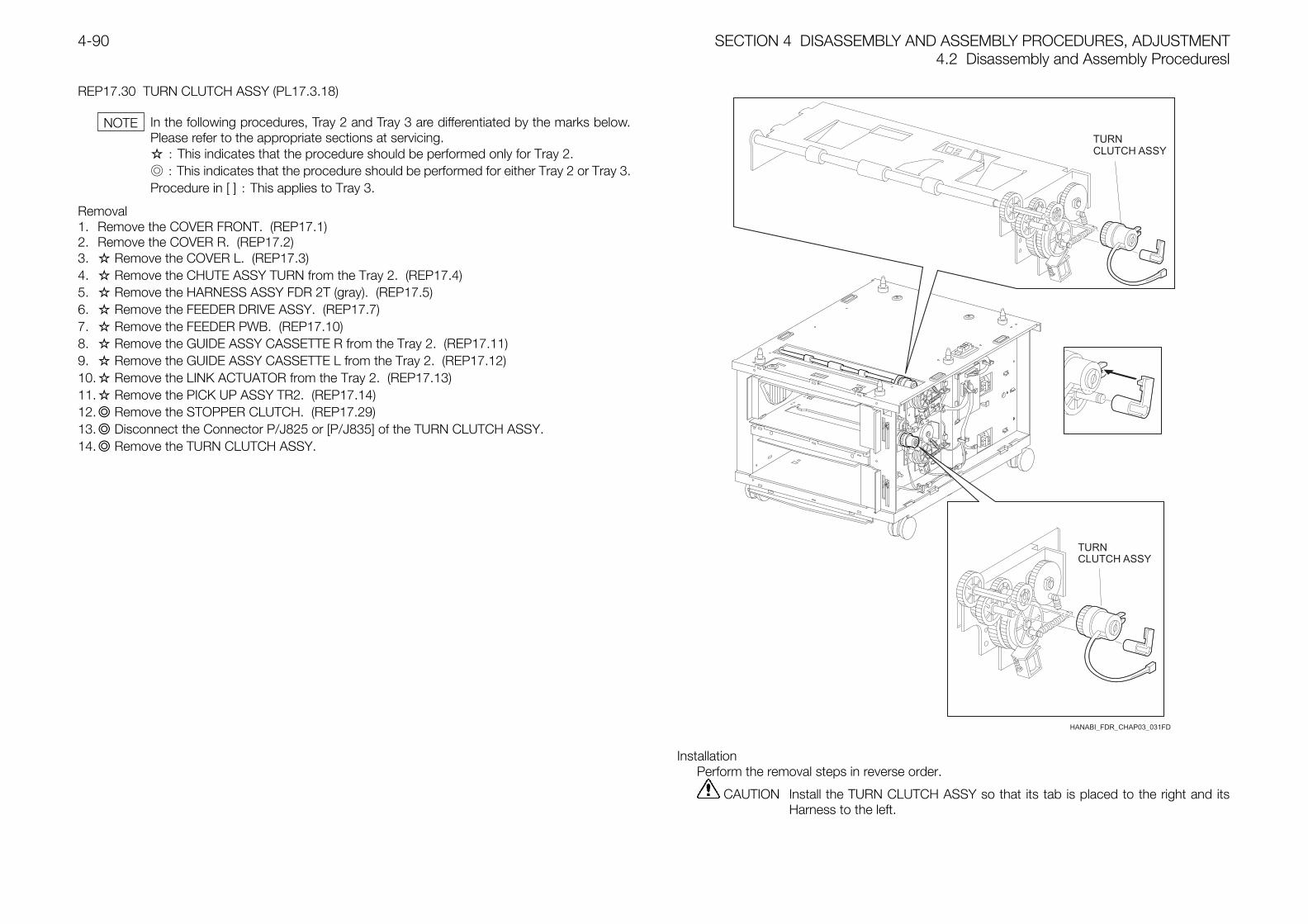
SECTION 4 DISASSEMBLY AND ASSEMBLY PROCEDURES, ADJUSTMENT4.2 Disassembly and Assembly Proceduresl
4-90
REP17.30 TURN CLUTCH ASSY (PL17.3.18)
In the following procedures, Tray 2 and Tray 3 are differentiated by the marks below.Please refer to the appropriate sections at servicing. : This indicates that the procedure should be performed only for Tray 2. : This indicates that the procedure should be performed for either Tray 2 or Tray 3.Procedure in [ ] : This applies to Tray 3.
Removal1. Remove the COVER FRONT. (REP17.1)2. Remove the COVER R. (REP17.2)3. Remove the COVER L. (REP17.3)4. Remove the CHUTE ASSY TURN from the Tray 2. (REP17.4)5. Remove the HARNESS ASSY FDR 2T (gray). (REP17.5)6. Remove the FEEDER DRIVE ASSY. (REP17.7)7. Remove the FEEDER PWB. (REP17.10)8. Remove the GUIDE ASSY CASSETTE R from the Tray 2. (REP17.11)9. Remove the GUIDE ASSY CASSETTE L from the Tray 2. (REP17.12)10. Remove the LINK ACTUATOR from the Tray 2. (REP17.13)11. Remove the PICK UP ASSY TR2. (REP17.14)12. Remove the STOPPER CLUTCH. (REP17.29)13. Disconnect the Connector P/J825 or [P/J835] of the TURN CLUTCH ASSY.14. Remove the TURN CLUTCH ASSY.
HANABI_FDR_CHAP03_031FD
InstallationPerform the removal steps in reverse order.
CAUTION Install the TURN CLUTCH ASSY so that its tab is placed to the right and itsHarness to the left.
NOTE
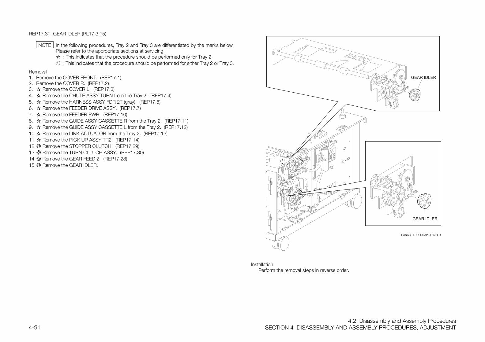
4.2 Disassembly and Assembly ProceduresSECTION 4 DISASSEMBLY AND ASSEMBLY PROCEDURES, ADJUSTMENT4-91
REP17.31 GEAR IDLER (PL17.3.15)
In the following procedures, Tray 2 and Tray 3 are differentiated by the marks below.Please refer to the appropriate sections at servicing. : This indicates that the procedure should be performed only for Tray 2. : This indicates that the procedure should be performed for either Tray 2 or Tray 3.
Removal1. Remove the COVER FRONT. (REP17.1)2. Remove the COVER R. (REP17.2)3. Remove the COVER L. (REP17.3)4. Remove the CHUTE ASSY TURN from the Tray 2. (REP17.4)5. Remove the HARNESS ASSY FDR 2T (gray). (REP17.5)6. Remove the FEEDER DRIVE ASSY. (REP17.7)7. Remove the FEEDER PWB. (REP17.10)8. Remove the GUIDE ASSY CASSETTE R from the Tray 2. (REP17.11)9. Remove the GUIDE ASSY CASSETTE L from the Tray 2. (REP17.12)10. Remove the LINK ACTUATOR from the Tray 2. (REP17.13)11. Remove the PICK UP ASSY TR2. (REP17.14)12. Remove the STOPPER CLUTCH. (REP17.29)13. Remove the TURN CLUTCH ASSY. (REP17.30)14. Remove the GEAR FEED 2. (REP17.28)15. Remove the GEAR IDLER.
HANABI_FDR_CHAP03_032FD
InstallationPerform the removal steps in reverse order.
NOTE
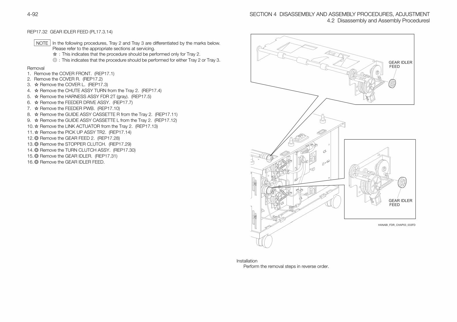
SECTION 4 DISASSEMBLY AND ASSEMBLY PROCEDURES, ADJUSTMENT4.2 Disassembly and Assembly Proceduresl
4-92
REP17.32 GEAR IDLER FEED (PL17.3.14)
In the following procedures, Tray 2 and Tray 3 are differentiated by the marks below.Please refer to the appropriate sections at servicing. : This indicates that the procedure should be performed only for Tray 2. : This indicates that the procedure should be performed for either Tray 2 or Tray 3.
Removal1. Remove the COVER FRONT. (REP17.1)2. Remove the COVER R. (REP17.2)3. Remove the COVER L. (REP17.3)4. Remove the CHUTE ASSY TURN from the Tray 2. (REP17.4)5. Remove the HARNESS ASSY FDR 2T (gray). (REP17.5)6. Remove the FEEDER DRIVE ASSY. (REP17.7)7. Remove the FEEDER PWB. (REP17.10)8. Remove the GUIDE ASSY CASSETTE R from the Tray 2. (REP17.11)9. Remove the GUIDE ASSY CASSETTE L from the Tray 2. (REP17.12)10. Remove the LINK ACTUATOR from the Tray 2. (REP17.13)11. Remove the PICK UP ASSY TR2. (REP17.14)12. Remove the GEAR FEED 2. (REP17.28)13. Remove the STOPPER CLUTCH. (REP17.29)14. Remove the TURN CLUTCH ASSY. (REP17.30)15. Remove the GEAR IDLER. (REP17.31)16. Remove the GEAR IDLER FEED.
HANABI_FDR_CHAP03_033FD
InstallationPerform the removal steps in reverse order.
NOTE
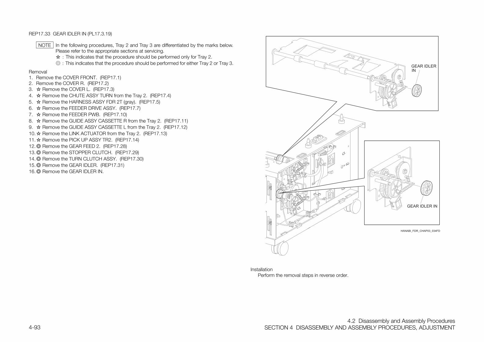
4.2 Disassembly and Assembly ProceduresSECTION 4 DISASSEMBLY AND ASSEMBLY PROCEDURES, ADJUSTMENT4-93
REP17.33 GEAR IDLER IN (PL17.3.19)
In the following procedures, Tray 2 and Tray 3 are differentiated by the marks below.Please refer to the appropriate sections at servicing. : This indicates that the procedure should be performed only for Tray 2. : This indicates that the procedure should be performed for either Tray 2 or Tray 3.
Removal1. Remove the COVER FRONT. (REP17.1)2. Remove the COVER R. (REP17.2)3. Remove the COVER L. (REP17.3)4. Remove the CHUTE ASSY TURN from the Tray 2. (REP17.4)5. Remove the HARNESS ASSY FDR 2T (gray). (REP17.5)6. Remove the FEEDER DRIVE ASSY. (REP17.7)7. Remove the FEEDER PWB. (REP17.10)8. Remove the GUIDE ASSY CASSETTE R from the Tray 2. (REP17.11)9. Remove the GUIDE ASSY CASSETTE L from the Tray 2. (REP17.12)10. Remove the LINK ACTUATOR from the Tray 2. (REP17.13)11. Remove the PICK UP ASSY TR2. (REP17.14)12. Remove the GEAR FEED 2. (REP17.28)13. Remove the STOPPER CLUTCH. (REP17.29)14. Remove the TURN CLUTCH ASSY. (REP17.30)15. Remove the GEAR IDLER. (REP17.31)16. Remove the GEAR IDLER IN.
HANABI_FDR_CHAP03_034FD
InstallationPerform the removal steps in reverse order.
NOTE
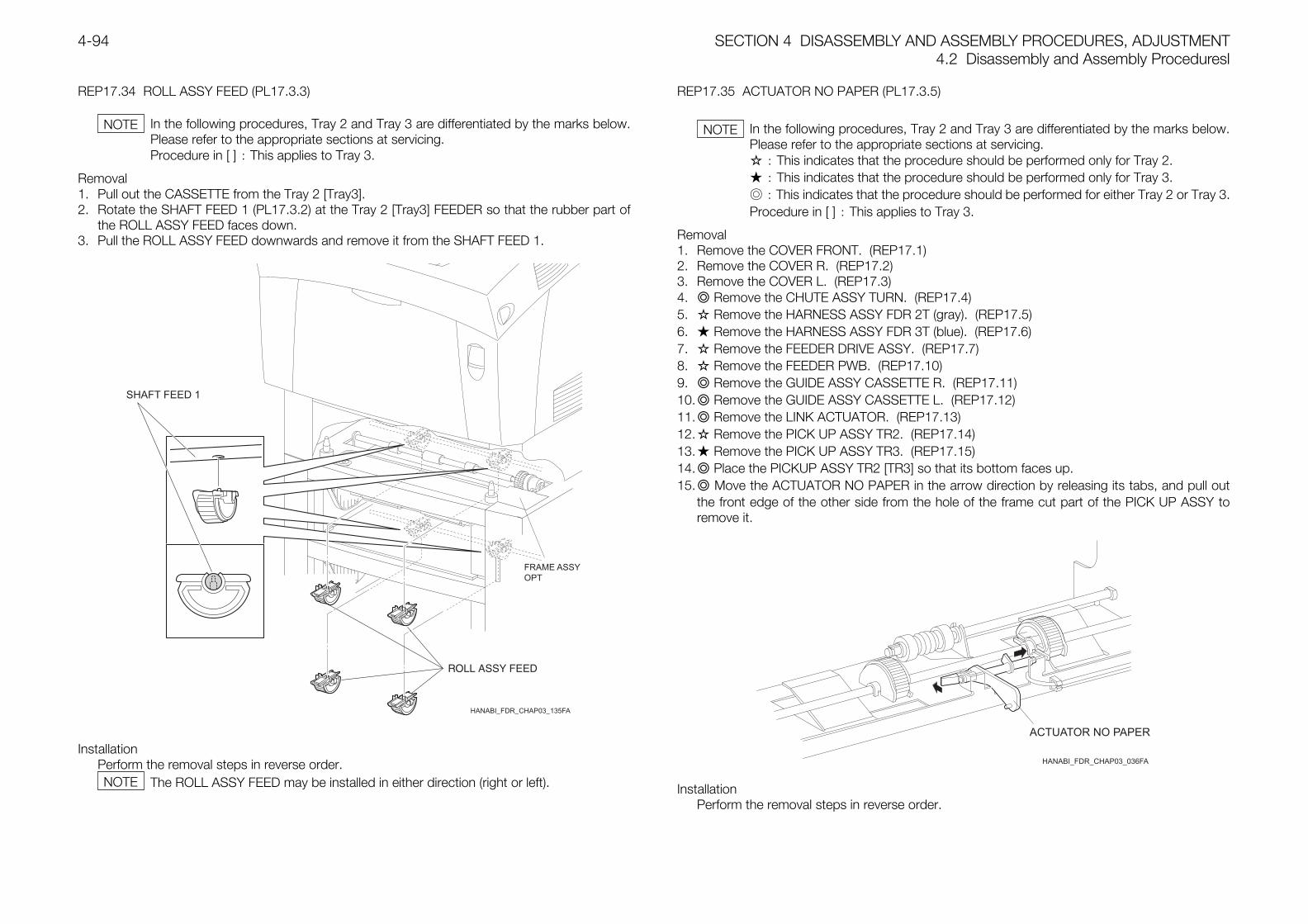
SECTION 4 DISASSEMBLY AND ASSEMBLY PROCEDURES, ADJUSTMENT4.2 Disassembly and Assembly Proceduresl
4-94
REP17.34 ROLL ASSY FEED (PL17.3.3)
In the following procedures, Tray 2 and Tray 3 are differentiated by the marks below.Please refer to the appropriate sections at servicing.Procedure in [ ] : This applies to Tray 3.
Removal1. Pull out the CASSETTE from the Tray 2 [Tray3].2. Rotate the SHAFT FEED 1 (PL17.3.2) at the Tray 2 [Tray3] FEEDER so that the rubber part of
the ROLL ASSY FEED faces down.3. Pull the ROLL ASSY FEED downwards and remove it from the SHAFT FEED 1.
HANABI_FDR_CHAP03_135FA
InstallationPerform the removal steps in reverse order.
The ROLL ASSY FEED may be installed in either direction (right or left).
REP17.35 ACTUATOR NO PAPER (PL17.3.5)
In the following procedures, Tray 2 and Tray 3 are differentiated by the marks below.Please refer to the appropriate sections at servicing. : This indicates that the procedure should be performed only for Tray 2. : This indicates that the procedure should be performed only for Tray 3. : This indicates that the procedure should be performed for either Tray 2 or Tray 3.Procedure in [ ] : This applies to Tray 3.
Removal1. Remove the COVER FRONT. (REP17.1)2. Remove the COVER R. (REP17.2)3. Remove the COVER L. (REP17.3)4. Remove the CHUTE ASSY TURN. (REP17.4)5. Remove the HARNESS ASSY FDR 2T (gray). (REP17.5)6. Remove the HARNESS ASSY FDR 3T (blue). (REP17.6)7. Remove the FEEDER DRIVE ASSY. (REP17.7)8. Remove the FEEDER PWB. (REP17.10)9. Remove the GUIDE ASSY CASSETTE R. (REP17.11)10. Remove the GUIDE ASSY CASSETTE L. (REP17.12)11. Remove the LINK ACTUATOR. (REP17.13)12. Remove the PICK UP ASSY TR2. (REP17.14)13. Remove the PICK UP ASSY TR3. (REP17.15)14. Place the PICKUP ASSY TR2 [TR3] so that its bottom faces up.15. Move the ACTUATOR NO PAPER in the arrow direction by releasing its tabs, and pull out
the front edge of the other side from the hole of the frame cut part of the PICK UP ASSY toremove it.
InstallationPerform the removal steps in reverse order.
NOTE NOTE
NOTE
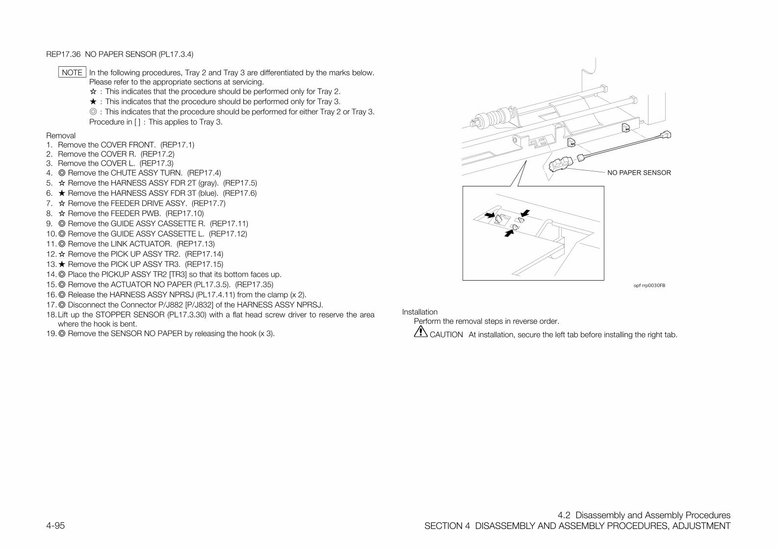
4.2 Disassembly and Assembly ProceduresSECTION 4 DISASSEMBLY AND ASSEMBLY PROCEDURES, ADJUSTMENT4-95
REP17.36 NO PAPER SENSOR (PL17.3.4)
In the following procedures, Tray 2 and Tray 3 are differentiated by the marks below.Please refer to the appropriate sections at servicing. : This indicates that the procedure should be performed only for Tray 2. : This indicates that the procedure should be performed only for Tray 3. : This indicates that the procedure should be performed for either Tray 2 or Tray 3.Procedure in [ ] : This applies to Tray 3.
Removal1. Remove the COVER FRONT. (REP17.1)2. Remove the COVER R. (REP17.2)3. Remove the COVER L. (REP17.3)4. Remove the CHUTE ASSY TURN. (REP17.4)5. Remove the HARNESS ASSY FDR 2T (gray). (REP17.5)6. Remove the HARNESS ASSY FDR 3T (blue). (REP17.6)7. Remove the FEEDER DRIVE ASSY. (REP17.7)8. Remove the FEEDER PWB. (REP17.10)9. Remove the GUIDE ASSY CASSETTE R. (REP17.11)10. Remove the GUIDE ASSY CASSETTE L. (REP17.12)11. Remove the LINK ACTUATOR. (REP17.13)12. Remove the PICK UP ASSY TR2. (REP17.14)13. Remove the PICK UP ASSY TR3. (REP17.15)14. Place the PICKUP ASSY TR2 [TR3] so that its bottom faces up.15. Remove the ACTUATOR NO PAPER (PL17.3.5). (REP17.35)16. Release the HARNESS ASSY NPRSJ (PL17.4.11) from the clamp (x 2).17. Disconnect the Connector P/J882 [P/J832] of the HARNESS ASSY NPRSJ.18.Lift up the STOPPER SENSOR (PL17.3.30) with a flat head screw driver to reserve the area
where the hook is bent.19. Remove the SENSOR NO PAPER by releasing the hook (x 3).
NO PAPER SENSOR
B
InstallationPerform the removal steps in reverse order.
CAUTION At installation, secure the left tab before installing the right tab.
NOTE
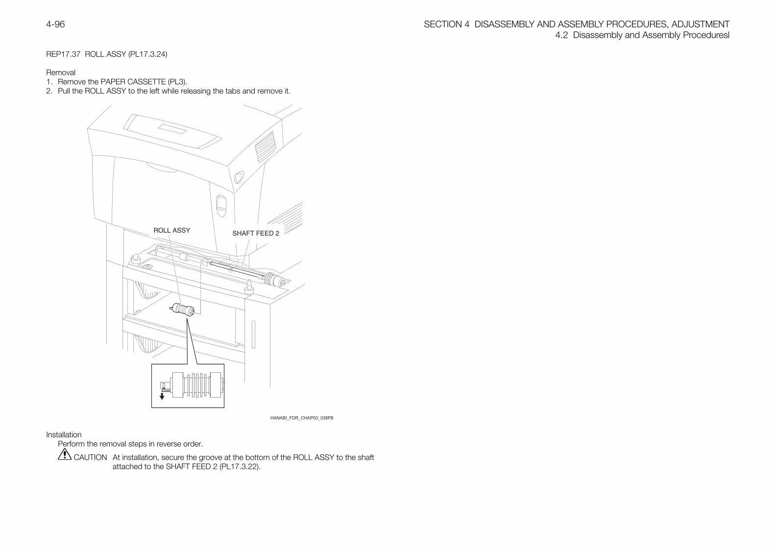
SECTION 4 DISASSEMBLY AND ASSEMBLY PROCEDURES, ADJUSTMENT4.2 Disassembly and Assembly Proceduresl
4-96
REP17.37 ROLL ASSY (PL17.3.24)
Removal1. Remove the PAPER CASSETTE (PL3).2. Pull the ROLL ASSY to the left while releasing the tabs and remove it.
InstallationPerform the removal steps in reverse order.
CAUTION At installation, secure the groove at the bottom of the ROLL ASSY to the shaftattached to the SHAFT FEED 2 (PL17.3.22).
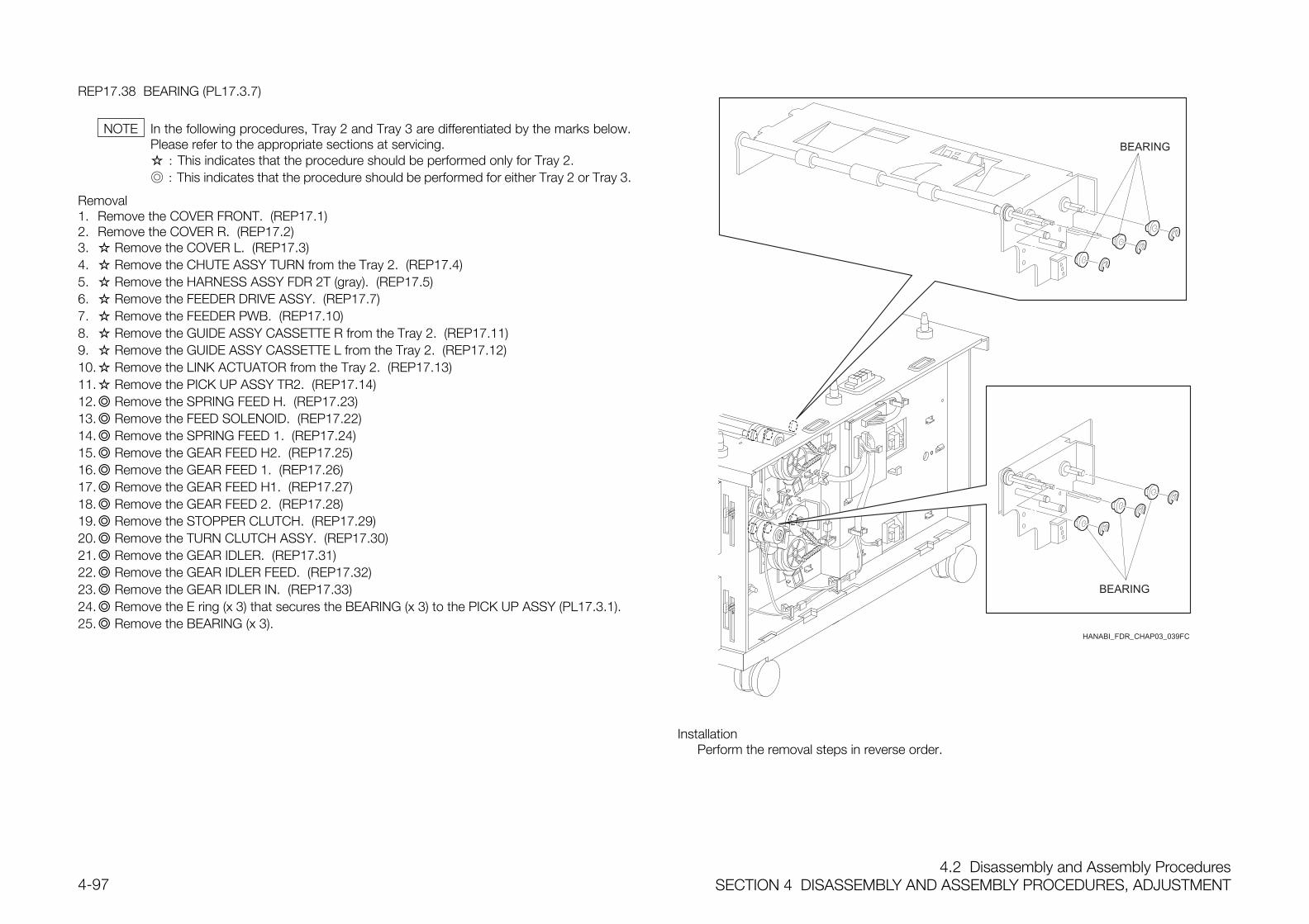
4.2 Disassembly and Assembly ProceduresSECTION 4 DISASSEMBLY AND ASSEMBLY PROCEDURES, ADJUSTMENT4-97
REP17.38 BEARING (PL17.3.7)
In the following procedures, Tray 2 and Tray 3 are differentiated by the marks below.Please refer to the appropriate sections at servicing. : This indicates that the procedure should be performed only for Tray 2. : This indicates that the procedure should be performed for either Tray 2 or Tray 3.
Removal1. Remove the COVER FRONT. (REP17.1)2. Remove the COVER R. (REP17.2)3. Remove the COVER L. (REP17.3)4. Remove the CHUTE ASSY TURN from the Tray 2. (REP17.4)5. Remove the HARNESS ASSY FDR 2T (gray). (REP17.5)6. Remove the FEEDER DRIVE ASSY. (REP17.7)7. Remove the FEEDER PWB. (REP17.10)8. Remove the GUIDE ASSY CASSETTE R from the Tray 2. (REP17.11)9. Remove the GUIDE ASSY CASSETTE L from the Tray 2. (REP17.12)10. Remove the LINK ACTUATOR from the Tray 2. (REP17.13)11. Remove the PICK UP ASSY TR2. (REP17.14)12. Remove the SPRING FEED H. (REP17.23)13. Remove the FEED SOLENOID. (REP17.22)14. Remove the SPRING FEED 1. (REP17.24)15. Remove the GEAR FEED H2. (REP17.25)16. Remove the GEAR FEED 1. (REP17.26)17. Remove the GEAR FEED H1. (REP17.27)18. Remove the GEAR FEED 2. (REP17.28)19. Remove the STOPPER CLUTCH. (REP17.29)20. Remove the TURN CLUTCH ASSY. (REP17.30)21. Remove the GEAR IDLER. (REP17.31)22. Remove the GEAR IDLER FEED. (REP17.32)23. Remove the GEAR IDLER IN. (REP17.33)24. Remove the E ring (x 3) that secures the BEARING (x 3) to the PICK UP ASSY (PL17.3.1).25. Remove the BEARING (x 3).
HANABI_FDR_CHAP03_039FC
InstallationPerform the removal steps in reverse order.
NOTE
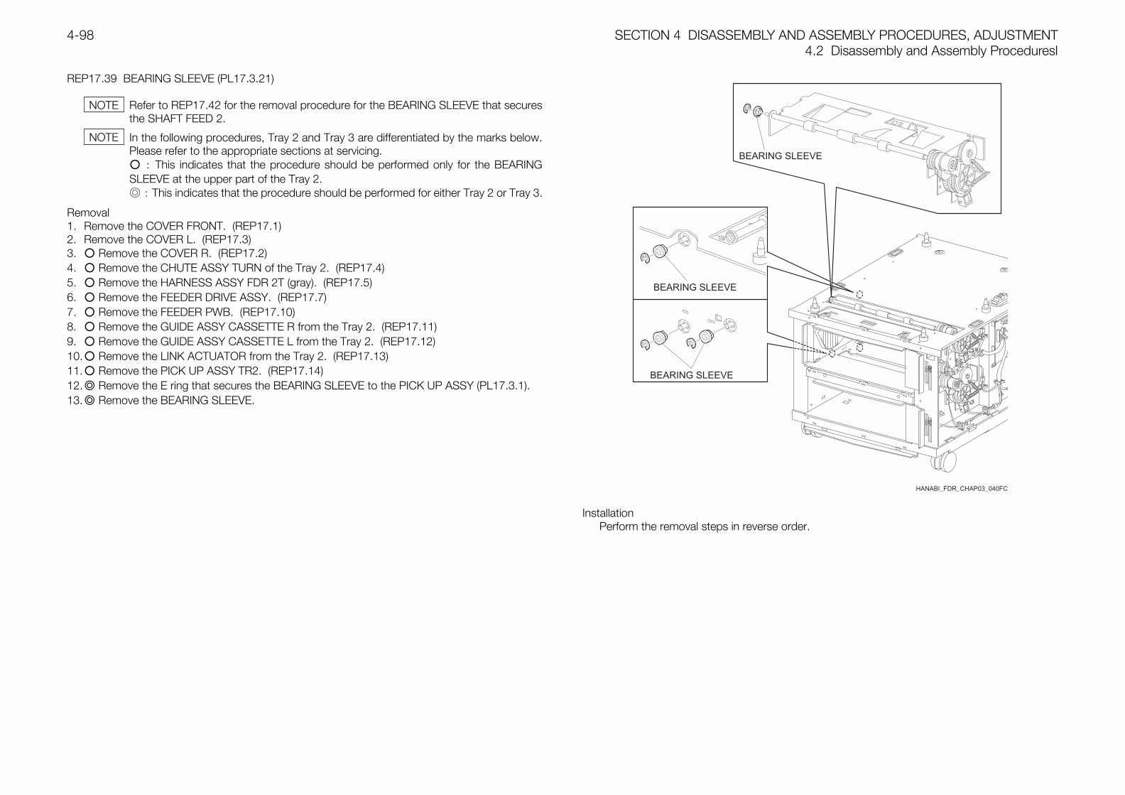
SECTION 4 DISASSEMBLY AND ASSEMBLY PROCEDURES, ADJUSTMENT4.2 Disassembly and Assembly Proceduresl
4-98
REP17.39 BEARING SLEEVE (PL17.3.21)
Refer to REP17.42 for the removal procedure for the BEARING SLEEVE that securesthe SHAFT FEED 2.
In the following procedures, Tray 2 and Tray 3 are differentiated by the marks below.Please refer to the appropriate sections at servicing. : This indicates that the procedure should be performed only for the BEARINGSLEEVE at the upper part of the Tray 2. : This indicates that the procedure should be performed for either Tray 2 or Tray 3.
Removal1. Remove the COVER FRONT. (REP17.1)2. Remove the COVER L. (REP17.3)3. Remove the COVER R. (REP17.2)4. Remove the CHUTE ASSY TURN of the Tray 2. (REP17.4)5. Remove the HARNESS ASSY FDR 2T (gray). (REP17.5)6. Remove the FEEDER DRIVE ASSY. (REP17.7)7. Remove the FEEDER PWB. (REP17.10)8. Remove the GUIDE ASSY CASSETTE R from the Tray 2. (REP17.11)9. Remove the GUIDE ASSY CASSETTE L from the Tray 2. (REP17.12)10. Remove the LINK ACTUATOR from the Tray 2. (REP17.13)11. Remove the PICK UP ASSY TR2. (REP17.14)12. Remove the E ring that secures the BEARING SLEEVE to the PICK UP ASSY (PL17.3.1).13. Remove the BEARING SLEEVE.
HANABI_FDR_CHAP03_040FC
InstallationPerform the removal steps in reverse order.
NOTE
NOTE
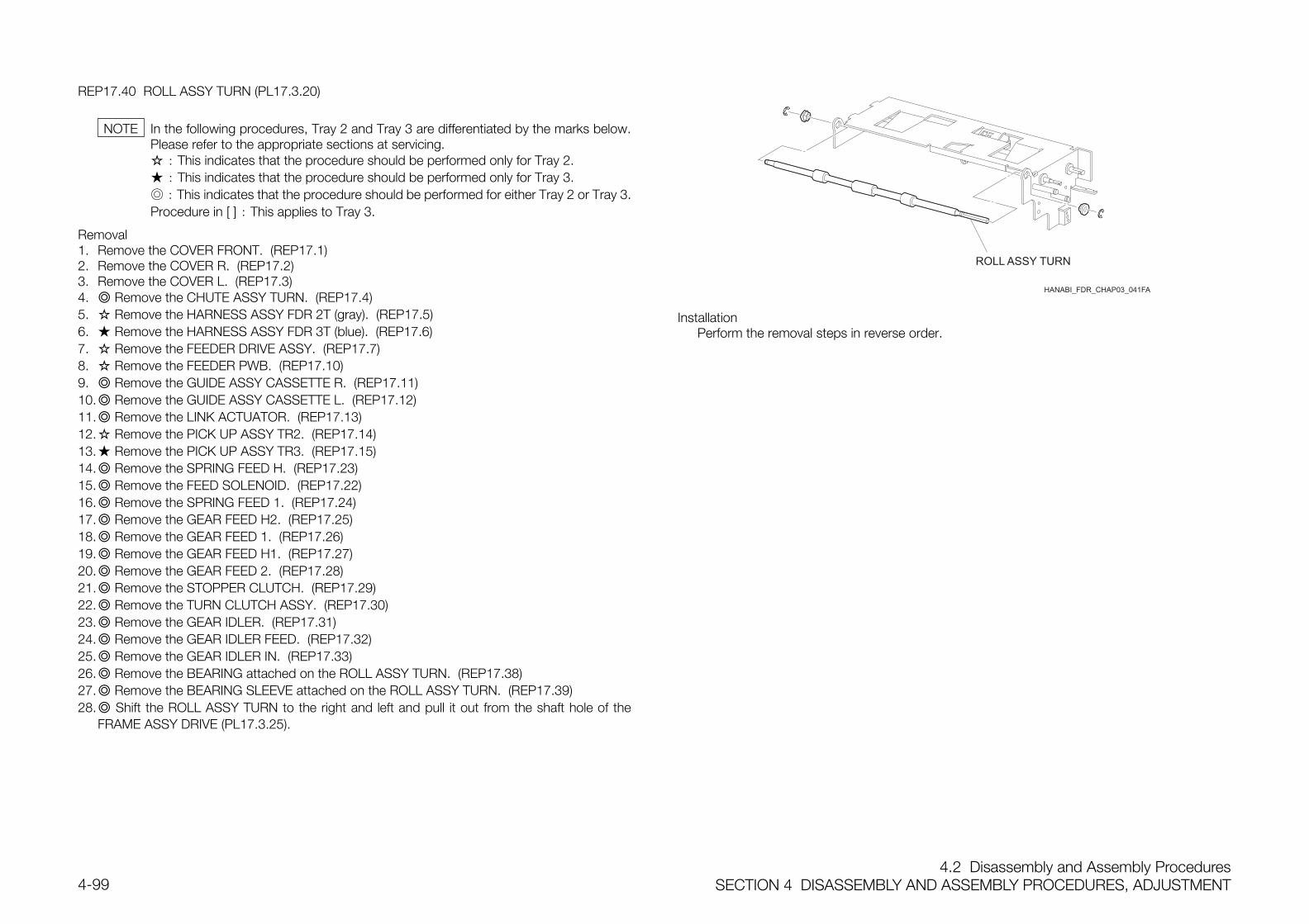
4.2 Disassembly and Assembly ProceduresSECTION 4 DISASSEMBLY AND ASSEMBLY PROCEDURES, ADJUSTMENT4-99
REP17.40 ROLL ASSY TURN (PL17.3.20)
In the following procedures, Tray 2 and Tray 3 are differentiated by the marks below.Please refer to the appropriate sections at servicing. : This indicates that the procedure should be performed only for Tray 2. : This indicates that the procedure should be performed only for Tray 3. : This indicates that the procedure should be performed for either Tray 2 or Tray 3.Procedure in [ ] : This applies to Tray 3.
Removal1. Remove the COVER FRONT. (REP17.1)2. Remove the COVER R. (REP17.2)3. Remove the COVER L. (REP17.3)4. Remove the CHUTE ASSY TURN. (REP17.4)5. Remove the HARNESS ASSY FDR 2T (gray). (REP17.5)6. Remove the HARNESS ASSY FDR 3T (blue). (REP17.6)7. Remove the FEEDER DRIVE ASSY. (REP17.7)8. Remove the FEEDER PWB. (REP17.10)9. Remove the GUIDE ASSY CASSETTE R. (REP17.11)10. Remove the GUIDE ASSY CASSETTE L. (REP17.12)11. Remove the LINK ACTUATOR. (REP17.13)12. Remove the PICK UP ASSY TR2. (REP17.14)13. Remove the PICK UP ASSY TR3. (REP17.15)14. Remove the SPRING FEED H. (REP17.23)15. Remove the FEED SOLENOID. (REP17.22)16. Remove the SPRING FEED 1. (REP17.24)17. Remove the GEAR FEED H2. (REP17.25)18. Remove the GEAR FEED 1. (REP17.26)19. Remove the GEAR FEED H1. (REP17.27)20. Remove the GEAR FEED 2. (REP17.28)21. Remove the STOPPER CLUTCH. (REP17.29)22. Remove the TURN CLUTCH ASSY. (REP17.30)23. Remove the GEAR IDLER. (REP17.31)24. Remove the GEAR IDLER FEED. (REP17.32)25. Remove the GEAR IDLER IN. (REP17.33)26. Remove the BEARING attached on the ROLL ASSY TURN. (REP17.38)27. Remove the BEARING SLEEVE attached on the ROLL ASSY TURN. (REP17.39)28. Shift the ROLL ASSY TURN to the right and left and pull it out from the shaft hole of the
FRAME ASSY DRIVE (PL17.3.25).
InstallationPerform the removal steps in reverse order.
NOTE
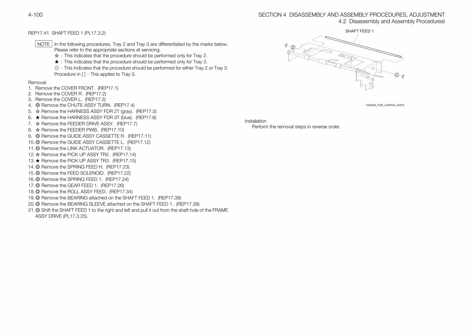
SECTION 4 DISASSEMBLY AND ASSEMBLY PROCEDURES, ADJUSTMENT4.2 Disassembly and Assembly Proceduresl
4-100
REP17.41 SHAFT FEED 1 (PL17.3.2)
In the following procedures, Tray 2 and Tray 3 are differentiated by the marks below.Please refer to the appropriate sections at servicing. : This indicates that the procedure should be performed only for Tray 2. : This indicates that the procedure should be performed only for Tray 3. : This indicates that the procedure should be performed for either Tray 2 or Tray 3.Procedure in [ ] : This applies to Tray 3.
Removal1. Remove the COVER FRONT. (REP17.1)2. Remove the COVER R. (REP17.2)3. Remove the COVER L. (REP17.3)4. Remove the CHUTE ASSY TURN. (REP17.4)5. Remove the HARNESS ASSY FDR 2T (gray). (REP17.5)6. Remove the HARNESS ASSY FDR 3T (blue). (REP17.6)7. Remove the FEEDER DRIVE ASSY. (REP17.7)8. Remove the FEEDER PWB. (REP17.10)9. Remove the GUIDE ASSY CASSETTE R. (REP17.11)10. Remove the GUIDE ASSY CASSETTE L. (REP17.12)11. Remove the LINK ACTUATOR. (REP17.13)12. Remove the PICK UP ASSY TR2. (REP17.14)13. Remove the PICK UP ASSY TR3. (REP17.15)14. Remove the SPRING FEED H. (REP17.23)15. Remove the FEED SOLENOID. (REP17.22)16. Remove the SPRING FEED 1. (REP17.24)17. Remove the GEAR FEED 1. (REP17.26)18. Remove the ROLL ASSY FEED. (REP17.34)19. Remove the BEARING attached on the SHAFT FEED 1. (REP17.38)20. Remove the BEARING SLEEVE attached on the SHAFT FEED 1. (REP17.39)21. Shift the SHAFT FEED 1 to the right and left and pull it out from the shaft hole of the FRAME
ASSY DRIVE (PL17.3.25).
InstallationPerform the removal steps in reverse order.
NOTE
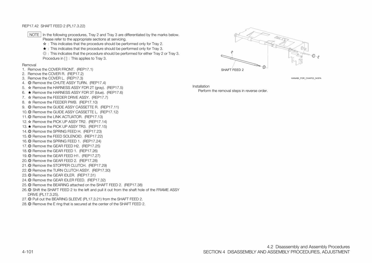
4.2 Disassembly and Assembly ProceduresSECTION 4 DISASSEMBLY AND ASSEMBLY PROCEDURES, ADJUSTMENT4-101
REP17.42 SHAFT FEED 2 (PL17.3.22)
In the following procedures, Tray 2 and Tray 3 are differentiated by the marks below.Please refer to the appropriate sections at servicing. : This indicates that the procedure should be performed only for Tray 2. : This indicates that the procedure should be performed only for Tray 3. : This indicates that the procedure should be performed for either Tray 2 or Tray 3.Procedure in [ ] : This applies to Tray 3.
Removal1. Remove the COVER FRONT. (REP17.1)2. Remove the COVER R. (REP17.2)3. Remove the COVER L. (REP17.3)4. Remove the CHUTE ASSY TURN. (REP17.4)5. Remove the HARNESS ASSY FDR 2T (gray). (REP17.5)6. Remove the HARNESS ASSY FDR 3T (blue). (REP17.6)7. Remove the FEEDER DRIVE ASSY. (REP17.7)8. Remove the FEEDER PWB. (REP17.10)9. Remove the GUIDE ASSY CASSETTE R. (REP17.11)10. Remove the GUIDE ASSY CASSETTE L. (REP17.12)11. Remove the LINK ACTUATOR. (REP17.13)12. Remove the PICK UP ASSY TR2. (REP17.14)13. Remove the PICK UP ASSY TR3. (REP17.15)14. Remove the SPRING FEED H. (REP17.23)15. Remove the FEED SOLENOID. (REP17.22)16. Remove the SPRING FEED 1. (REP17.24)17. Remove the GEAR FEED H2. (REP17.25)18. Remove the GEAR FEED 1. (REP17.26)19. Remove the GEAR FEED H1. (REP17.27)20. Remove the GEAR FEED 2. (REP17.28)21. Remove the STOPPER CLUTCH. (REP17.29)22. Remove the TURN CLUTCH ASSY. (REP17.30)23. Remove the GEAR IDLER. (REP17.31)24. Remove the GEAR IDLER FEED. (REP17.32)25. Remove the BEARING attached on the SHAFT FEED 2. (REP17.38)26. Shift the SHAFT FEED 2 to the left and pull it out from the shaft hole of the FRAME ASSY
DRIVE (PL17.3.25).27. Pull out the BEARING SLEEVE (PL17.3.21) from the SHAFT FEED 2.28. Remove the E ring that is secured at the center of the SHAFT FEED 2.
InstallationPerform the removal steps in reverse order.
NOTE
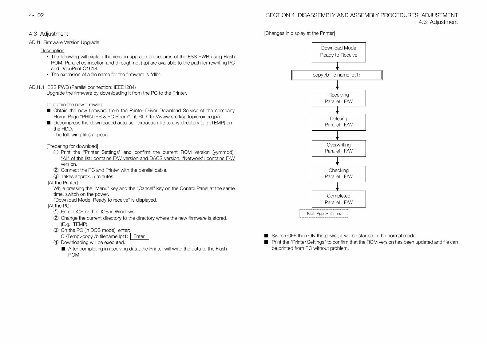
SECTION 4 DISASSEMBLY AND ASSEMBLY PROCEDURES, ADJUSTMENT4.3 Adjustment
4-102
4.3 AdjustmentADJ1 Firmware Version Upgrade
Description・ The following will explain the version upgrade procedures of the ESS PWB using Flash
ROM. Parallel connection and through net (ftp) are available to the path for rewriting PCand DocuPrint C1618.
・ The extension of a file name for the firmware is "dlb".
ADJ1.1 ESS PWB (Parallel connection: IEEE1284)Upgrade the firmware by downloading it from the PC to the Printer.
To obtain the new firmware Obtain the new firmware from the Printer Driver Download Service of the company
Home Page "PRINTER & PC Room". (URL http://www.src.ksp.fujixerox.co.jp/) Decompress the downloaded auto-self-extraction file to any directory (e.g.:TEMP) on
the HDD.The following files appear.
[Preparing for download]① Print the "Printer Settings" and confirm the current ROM version (yymmdd).
"All" of the list: contains F/W version and DACS version, "Network": contains F/Wversion.
② Connect the PC and Printer with the parallel cable.③ Takes approx. 5 minutes.
[At the Printer]While pressing the "Menu" key and the "Cancel" key on the Control Panel at the sametime, switch on the power."Download Mode Ready to receive" is displayed.
[At the PC]① Enter DOS or the DOS in Windows.② Change the current directory to the directory where the new firmware is stored.
(E.g.: TEMP).③ On the PC (in DOS mode), enter:
C:\Temp>copy /b filename lpt1:④ Downloading will be executed.
After completing in receiving data, the Printer will write the data to the FlashROM.
[Changes in display at the Printer]
Switch OFF then ON the power, it will be started in the normal mode. Print the "Printer Settings" to confirm that the ROM version has been updated and file can
be printed from PC without problem.
Download ModeReady to Receive
copy /b file name lpt1:
Total: Approx. 5 mins
ReceivingParallel F/W
DeletingParallel F/W
OverwritingParallel F/W
CheckingParallel F/W
CompletedParallel F/W
Enter
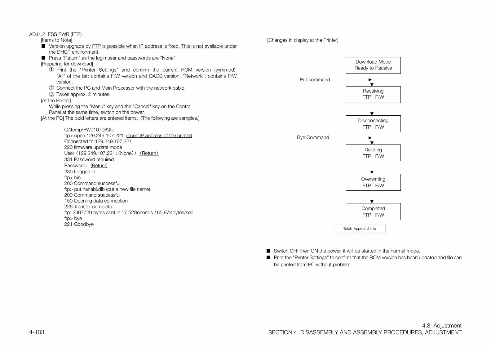
4.3 AdjustmentSECTION 4 DISASSEMBLY AND ASSEMBLY PROCEDURES, ADJUSTMENT4-103
ADJ1.2 ESS PWB (FTP)[Items to Note] Version upgrade by FTP is possible when IP address is fixed. This is not available under
the DHCP environment. Press "Return" as the login user and passwords are "None".[Preparing for download]
① Print the "Printer Settings" and confirm the current ROM version (yymmdd)."All" of the list: contains F/W version and DACS version, "Network": contains F/Wversion.
② Connect the PC and Main Processor with the network cable.③ Takes approx. 2 minutes.
[At the Printer]While pressing the "Menu" key and the "Cancel" key on the Control
Panel at the same time, switch on the power.[At the PC] The bold letters are entered items. (The following are samples.)
C:\temp\FW010706\ftpftp> open 129.249.107.221 (open IP address of the printer)Connected to 129.249.107.221220 firmware update modeUser (129.249.107.221:(None)) (Return)331 Password requiredPassword: (Return)230 Logged inftp> bin200 Command successfulftp> put hanabi.dlb (put a new file name)200 Command successful150 Opening data connection226 Transfer completeftp: 2907729 bytes sent in 17.52Seconds 165.97Kbytes/secftp> bye221 Goodbye
[Changes in display at the Printer]
Switch OFF then ON the power, it will be started in the normal mode. Print the "Printer Settings" to confirm that the ROM version has been updated and file can
be printed from PC without problem.
Download ModeReady to Receive
Total: Approx. 2 mis
DisconnectingFTP F/W
ReceivingFTP F/W
DeletingFTP F/W
OverwritingFTP F/W
CompletedFTP F/W
Put command
Bye Command

SECTION 5 PARTS LIST
ContentsSECTION 5 PARTS LIST5-1
Contents
5.1.1 Preface........................................................................................................ 2
5.1.2 How to use Parts List................................................................................... 2
5.1.3 General Notes on Parts List ......................................................................... 2
5.1.4 General Notes on Parts List ......................................................................... 2
5.2 Parts List ........................................................................................................... 3
PL1.1 Cover (1/2) ............................................................................................ 3
PL1.2 Cover (2/2) ............................................................................................ 4
PL2.1 Chassis & Feeder/Cassette...................................................................... 5
PL3.1 Paper Cassette (1/2)................................................................................ 6
PL3.2 Paper Cassette (2/2)................................................................................ 7
PL4.1 Paper Feeder (1/3)................................................................................... 8
PL4.2 Paper Feeder (2/3)................................................................................... 9
PL4.3 Paper Feeder (3/3)................................................................................. 10
PL5.1 Housing Assy Retard ............................................................................. 11
PL6.1 Chute Assy In (1/2) ................................................................................ 12
PL6.2 Chute Assy In (2/2) ................................................................................ 13
PL7.1 Chute Assy Out (1/2) ............................................................................. 14
PL7.2 Chute Assy Out (2/2) ............................................................................. 15
PL8.1 Chute Assy Exit ..................................................................................... 16
PL9.1 BTR Assy & Fuser ................................................................................. 17
PL10.1 Registration ......................................................................................... 18
PL11.1 Xerographics ....................................................................................... 19
PL12.1 TCRU Assy (1/3).................................................................................. 20
PL12.2 TCRU Assy (2/3).................................................................................. 21
PL12.3 TCRU Assy (3/3).................................................................................. 22
PL13.1 Frame.................................................................................................. 23
PL14.1 DRIVE ................................................................................................. 24
PL15.1 Electrical (1/2) ......................................................................................25
PL15.2 Electrical (2/2) ......................................................................................26
PL16.1 ESS.....................................................................................................27
PL17.1 2Tray Module (1/4) ...............................................................................28
PL17.2 2Tray Module (2/4) ...............................................................................29
PL17.3 2Tray Module (3/4) ...............................................................................30
PL17.4 2Tray Module (4/4) ...............................................................................31
PL18.1 Option Paper Cassette (1/2).................................................................32
PL18.2 Option Paper Cassette (2/2).................................................................33
5.3 Area Codes for Adjustments/Consumables ......................................................34
SECTION 5 PARTS LIST5.2 Parts List
5-2
5.1.1 Preface
5.1.2 How to use Parts ListThis section contains information related to spare parts, which is used whenordering replacement parts and entering area codes.This Parts List is to be read in conjunction with the following description.
5.1.3 General Notes on Parts List
① If a "Note" is found in the DESCRIPTION column, read the corresponding Notebefore proceeding.
② Area Codes are found on the respective plates.Area Codes which cannot be indicated by the parts on respective plates (suchas toner and electric current adjustment value) can be found in the Area CodeTable at the end of this section.
5.1.4 General Notes on Parts List Numbers in the illustrations are the Item numbers in the list and they indicate the
relationship between illustrations and part names. PL "X.Y.Z" indicates a part for item "Z" on the plate (PL) "X.Y". Alphabets in the illustrations denote screws, clips and so on.
"S"= screw, "E"= E ring, "KL"= KL clip, "C"= C ring, "N"= nut "(With 2-5)" appearing in illustrations and assembly parts in the list indicates that
items "2, 3, 4, 5" are shown on that plate. "[Same PL X.Y.Z]" appearing in illustrations and assembly parts in the list
indicates that that part is the same as the part for item "Z" on plate "X.Y". "HIGH ASSY" in the list indicates that assembly parts in a higher assembly
contain that part.
5.2 Parts ListSECTION 5 PARTS LIST5-3
5.2 Parts List
PL1.1 Cover (1/2) ITEM PARTS No. DESCRIPTION A.C
1 802K 30770 CONTROL PANEL HANABI 75AA
2 802K 18340 COVER ASSY FRONT HEAD(with 3-9) 32B1
3 892E 41500 COVER FRONT HEAD 32B2
4 892E 41230 LABEL XEROX 32B3
5 19E 48220 HOLDER LEVER OUT 32B4
6 26E 24880 SCREW(M3x10) 32B5
7 11E 10660 LEVER OUT 32B6
8 -- CON. AMP 175694-3 32B7
9 127E 82890 FUSER FAN 32B8
10 -- COVER TOP STOPPER 32B9
11 802E 22920 COVER TOP 32BB
12 802K 28090 COVER TOP MAIN(with 13,14) 32BC
13 -- COVER TOP MAIN 32BX
14 892E 52840 LABEL TONER SETTING 32BE
15 802K 18360 COVER ASSY TOP PHD(with 16-26) 32BF
16 8E 93870 CAM I/R 32BG
17 802E 22630 COVER CAM 32BH
18 809E 28210 SPRING CAM I/R 32BJ
19 3E 53230 LATCH TOP R 32BK
20 3E 53240 HANDLE TOP 32BL
21 6E 71880 SHAFT LATCH TOP 32BM
22 809E 28240 SPRING HANDLE 32BN
23 3E 53220 LATCH TOP L 32BP
24 802E 22550 COVER TOP PHD 32BQ
25 809E 28220 SPRING TOP L 32BR
26 809E 28230 SPRING TOP R 32BS
27 3E 30350 STOPPER CRU 32BT
28 802E 22930 COVER REAR 32BU
29 26E 76270 STUD TOP 32BW
SECTION 5 PARTS LIST5.2 Parts List
5-4
PL1.2 Cover (2/2)ITEM PARTS No. DESCRIPTION A.C
1 802E 22970 COVER SIDE L 32C1
2 802K 42820 COVER SIDE R 32C2
3 26E 87840 SCREW(M3x8) 32C3
4 809E 28570 SPRING LINK 32C4
5 12E 10050 LINK 32C5
6 802K 18330 COVER ASSY FRONT(with 7-9) 32C6
7 26E 24880 SCREW(M3x10) 32C7
8 809E 28200 SPRING LINK 32C8
9 -- COVER FRONT 32C9
10 802K 18350 COVER ASSY FRONT IN(with 7,8,11) 32CB
11 -- COVER FRONT IN 32CC
12 50K 42910 TRAY ASSY MSI(with 13-18) 5110
13 -- LABEL REGI 32CD
14 32E 16130 GUIDE SIDE 32CE
15 50E 16940 TRAY MSI BASE 32CF
16 7E 65830 RACK MSI 32CG
17 7E 65820 GEAR MANUAL 32CH
18 26E 29050 SCREW FLANGE 32CJ
19 50K 42750 TRAY ASSY LOW(with 20,21) 32CK
20 50E 16870 TRAY MSI SLIDE 32CL
21 -- COVER MSI 32CM
5.2 Parts ListSECTION 5 PARTS LIST5-5
PL2.1 Chassis & Feeder/CassetteITEM PARTS No. DESCRIPTION A.C
1 84K 3097 CHASSIS HI ASSY FX 31B1
2 84K 3036 FDR/CST ASSY FX 5010
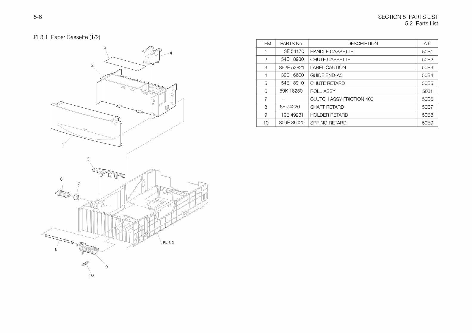
SECTION 5 PARTS LIST5.2 Parts List
5-6
PL3.1 Paper Cassette (1/2)
PL 3.2
ITEM PARTS No. DESCRIPTION A.C
1 3E 54170 HANDLE CASSETTE 50B1
2 54E 18930 CHUTE CASSETTE 50B2
3 892E 52821 LABEL CAUTION 50B3
4 32E 16600 GUIDE END-A5 50B4
5 54E 18910 CHUTE RETARD 50B5
6 59K 18250 ROLL ASSY 5031
7 -- CLUTCH ASSY FRICTION 400 50B6
8 6E 74220 SHAFT RETARD 50B7
9 19E 49231 HOLDER RETARD 50B8
10 809E 36020 SPRING RETARD 50B9
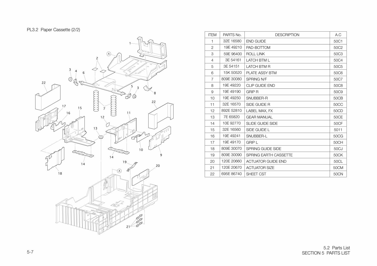
5.2 Parts ListSECTION 5 PARTS LIST5-7
PL3.2 Paper Cassette (2/2)ITEM PARTS No. DESCRIPTION A.C
1 32E 16580 END GUIDE 50C1
2 19E 49210 PAD-BOTTOM 50C2
3 59E 96400 ROLL LINK 50C3
4 3E 54161 LATCH BTM L 50C4
5 3E 54151 LATCH BTM R 50C5
6 15K 50520 PLATE ASSY BTM 50C6
7 809E 30080 SPRING N/F 50C7
8 19E 49220 CLIP GUIDE END 50C8
9 19E 49190 GRIP R 50C9
10 19E 49250 SNUBBER-R 50CB
11 32E 16570 SIDE GUIDE R 50CC
12 892E 52810 LABEL MAX, FX 50CD
13 7E 65820 GEAR MANUAL 50CE
14 10E 92770 SLIDE GUIDE SIDE 50CF
15 32E 16560 SIDE GUIDE L 5011
16 19E 49241 SNUBBER-L 50CG
17 19E 49170 GRIP L 50CH
18 809E 30070 SPRING GUIDE SIDE 50CJ
19 809E 30090 SPRING EARTH CASSETTE 50CK
20 120E 20660 ACTUATOR GUIDE END 50CL
21 120E 20670 ACTUATOR SIZE 50CM
22 695E 86740 SHEET CST 50CN
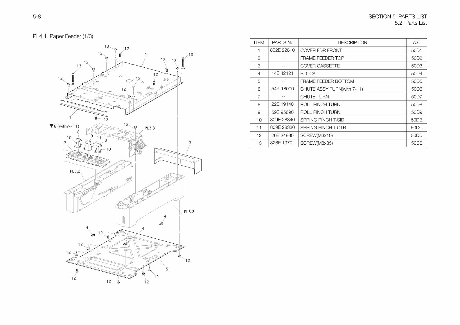
SECTION 5 PARTS LIST5.2 Parts List
5-8
PL4.1 Paper Feeder (1/3)ITEM PARTS No. DESCRIPTION A.C
1 802E 22810 COVER FDR FRONT 50D1
2 -- FRAME FEEDER TOP 50D2
3 -- COVER CASSETTE 50D3
4 14E 42121 BLOCK 50D4
5 -- FRAME FEEDER BOTTOM 50D5
6 54K 18000 CHUTE ASSY TURN(with 7-11) 50D6
7 -- CHUTE TURN 50D7
8 22E 19140 ROLL PINCH TURN 50D8
9 59E 95690 ROLL PINCH TURN 50D9
10 809E 28340 SPRING PINCH T-SID 50DB
11 809E 28330 SPRING PINCH T-CTR 50DC
12 26E 24880 SCREW(M3x10) 50DD
13 826E 1970 SCREW(M3x85) 50DE
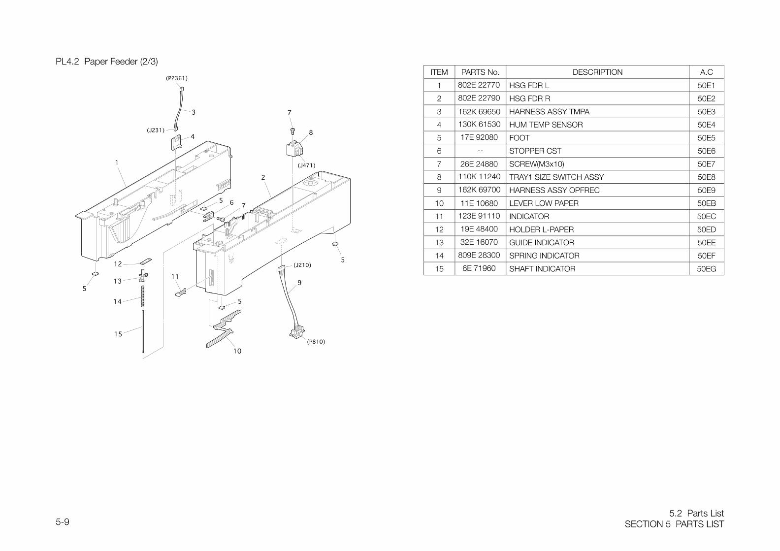
5.2 Parts ListSECTION 5 PARTS LIST5-9
PL4.2 Paper Feeder (2/3)ITEM PARTS No. DESCRIPTION A.C
1 802E 22770 HSG FDR L 50E1
2 802E 22790 HSG FDR R 50E2
3 162K 69650 HARNESS ASSY TMPA 50E3
4 130K 61530 HUM TEMP SENSOR 50E4
5 17E 92080 FOOT 50E5
6 -- STOPPER CST 50E6
7 26E 24880 SCREW(M3x10) 50E7
8 110K 11240 TRAY1 SIZE SWITCH ASSY 50E8
9 162K 69700 HARNESS ASSY OPFREC 50E9
10 11E 10680 LEVER LOW PAPER 50EB
11 123E 91110 INDICATOR 50EC
12 19E 48400 HOLDER L-PAPER 50ED
13 32E 16070 GUIDE INDICATOR 50EE
14 809E 28300 SPRING INDICATOR 50EF
15 6E 71960 SHAFT INDICATOR 50EG
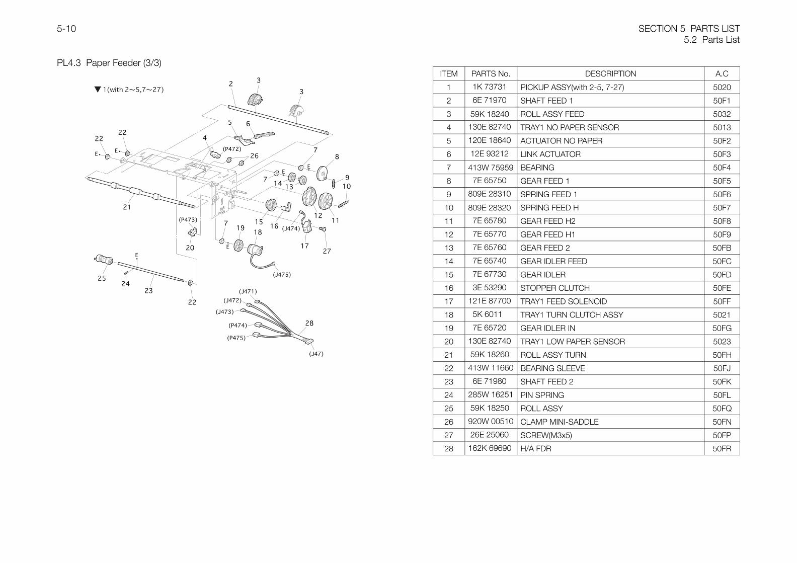
SECTION 5 PARTS LIST5.2 Parts List
5-10
PL4.3 Paper Feeder (3/3)ITEM PARTS No. DESCRIPTION A.C
1 1K 73731 PICKUP ASSY(with 2-5, 7-27) 5020
2 6E 71970 SHAFT FEED 1 50F1
3 59K 18240 ROLL ASSY FEED 5032
4 130E 82740 TRAY1 NO PAPER SENSOR 5013
5 120E 18640 ACTUATOR NO PAPER 50F2
6 12E 93212 LINK ACTUATOR 50F3
7 413W 75959 BEARING 50F4
8 7E 65750 GEAR FEED 1 50F5
9 809E 28310 SPRING FEED 1 50F6
10 809E 28320 SPRING FEED H 50F7
11 7E 65780 GEAR FEED H2 50F8
12 7E 65770 GEAR FEED H1 50F9
13 7E 65760 GEAR FEED 2 50FB
14 7E 65740 GEAR IDLER FEED 50FC
15 7E 67730 GEAR IDLER 50FD
16 3E 53290 STOPPER CLUTCH 50FE
17 121E 87700 TRAY1 FEED SOLENOID 50FF
18 5K 6011 TRAY1 TURN CLUTCH ASSY 5021
19 7E 65720 GEAR IDLER IN 50FG
20 130E 82740 TRAY1 LOW PAPER SENSOR 5023
21 59K 18260 ROLL ASSY TURN 50FH
22 413W 11660 BEARING SLEEVE 50FJ
23 6E 71980 SHAFT FEED 2 50FK
24 285W 16251 PIN SPRING 50FL
25 59K 18250 ROLL ASSY 50FQ
26 920W 00510 CLAMP MINI-SADDLE 50FN
27 26E 25060 SCREW(M3x5) 50FP
28 162K 69690 H/A FDR 50FR
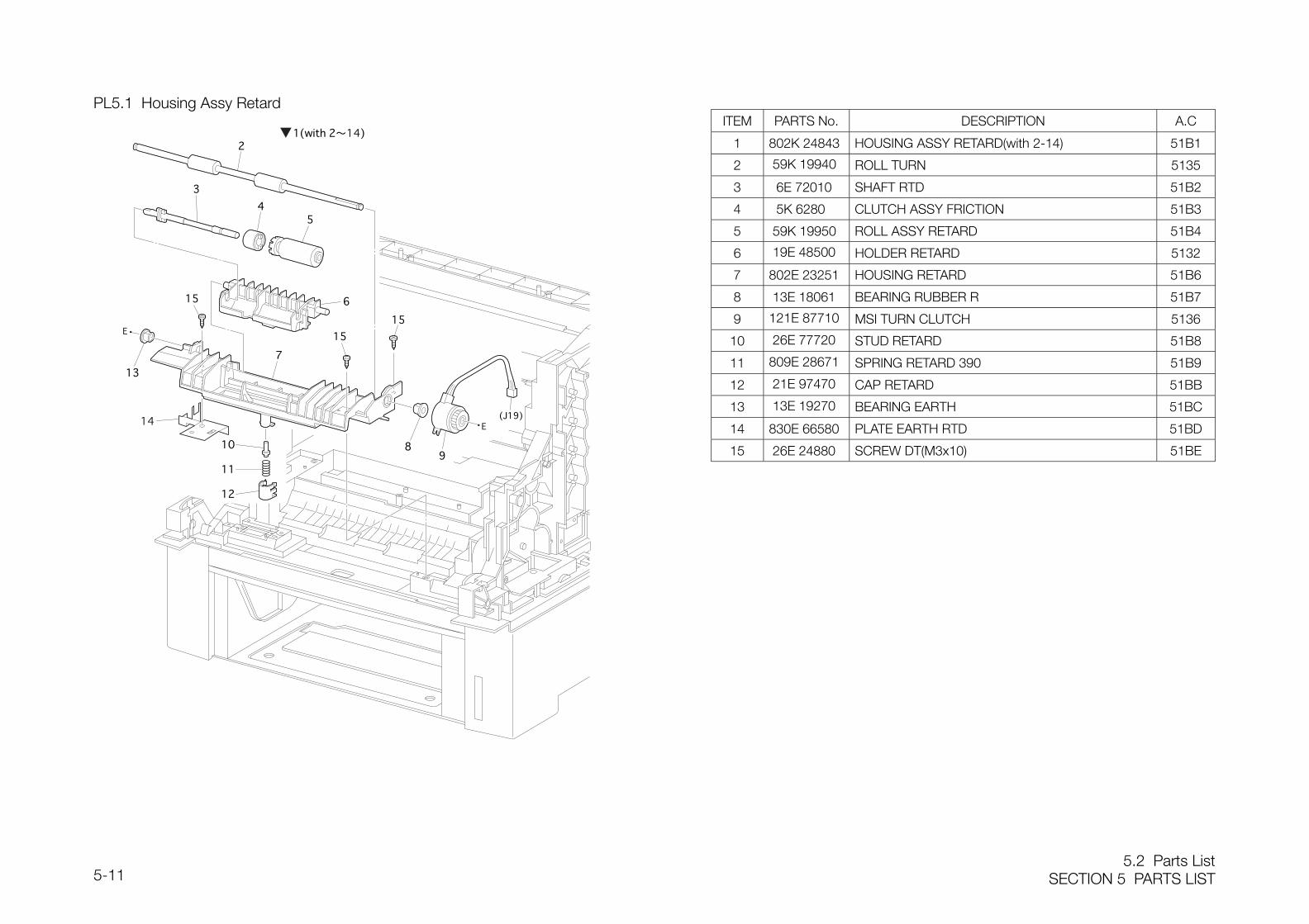
5.2 Parts ListSECTION 5 PARTS LIST5-11
PL5.1 Housing Assy RetardITEM PARTS No. DESCRIPTION A.C
1 802K 24843 HOUSING ASSY RETARD(with 2-14) 51B1
2 59K 19940 ROLL TURN 5135
3 6E 72010 SHAFT RTD 51B2
4 5K 6280 CLUTCH ASSY FRICTION 51B3
5 59K 19950 ROLL ASSY RETARD 51B4
6 19E 48500 HOLDER RETARD 5132
7 802E 23251 HOUSING RETARD 51B6
8 13E 18061 BEARING RUBBER R 51B7
9 121E 87710 MSI TURN CLUTCH 5136
10 26E 77720 STUD RETARD 51B8
11 809E 28671 SPRING RETARD 390 51B9
12 21E 97470 CAP RETARD 51BB
13 13E 19270 BEARING EARTH 51BC
14 830E 66580 PLATE EARTH RTD 51BD
15 26E 24880 SCREW DT(M3x10) 51BE
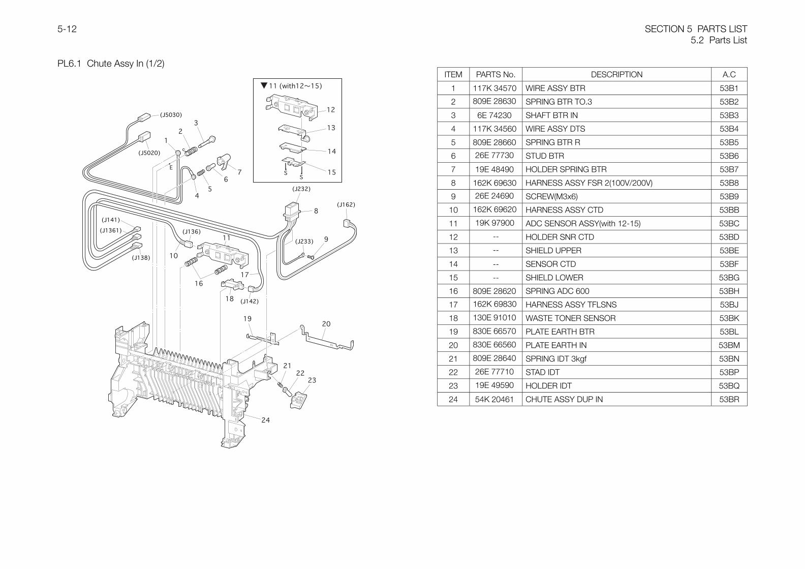
SECTION 5 PARTS LIST5.2 Parts List
5-12
PL6.1 Chute Assy In (1/2)ITEM PARTS No. DESCRIPTION A.C
1 117K 34570 WIRE ASSY BTR 53B1
2 809E 28630 SPRING BTR TO.3 53B2
3 6E 74230 SHAFT BTR IN 53B3
4 117K 34560 WIRE ASSY DTS 53B4
5 809E 28660 SPRING BTR R 53B5
6 26E 77730 STUD BTR 53B6
7 19E 48490 HOLDER SPRING BTR 53B7
8 162K 69630 HARNESS ASSY FSR 2(100V/200V) 53B8
9 26E 24690 SCREW(M3x6) 53B9
10 162K 69620 HARNESS ASSY CTD 53BB
11 19K 97900 ADC SENSOR ASSY(with 12-15) 53BC
12 -- HOLDER SNR CTD 53BD
13 -- SHIELD UPPER 53BE
14 -- SENSOR CTD 53BF
15 -- SHIELD LOWER 53BG
16 809E 28620 SPRING ADC 600 53BH
17 162K 69830 HARNESS ASSY TFLSNS 53BJ
18 130E 91010 WASTE TONER SENSOR 53BK
19 830E 66570 PLATE EARTH BTR 53BL
20 830E 66560 PLATE EARTH IN 53BM
21 809E 28640 SPRING IDT 3kgf 53BN
22 26E 77710 STAD IDT 53BP
23 19E 49590 HOLDER IDT 53BQ
24 54K 20461 CHUTE ASSY DUP IN 53BR
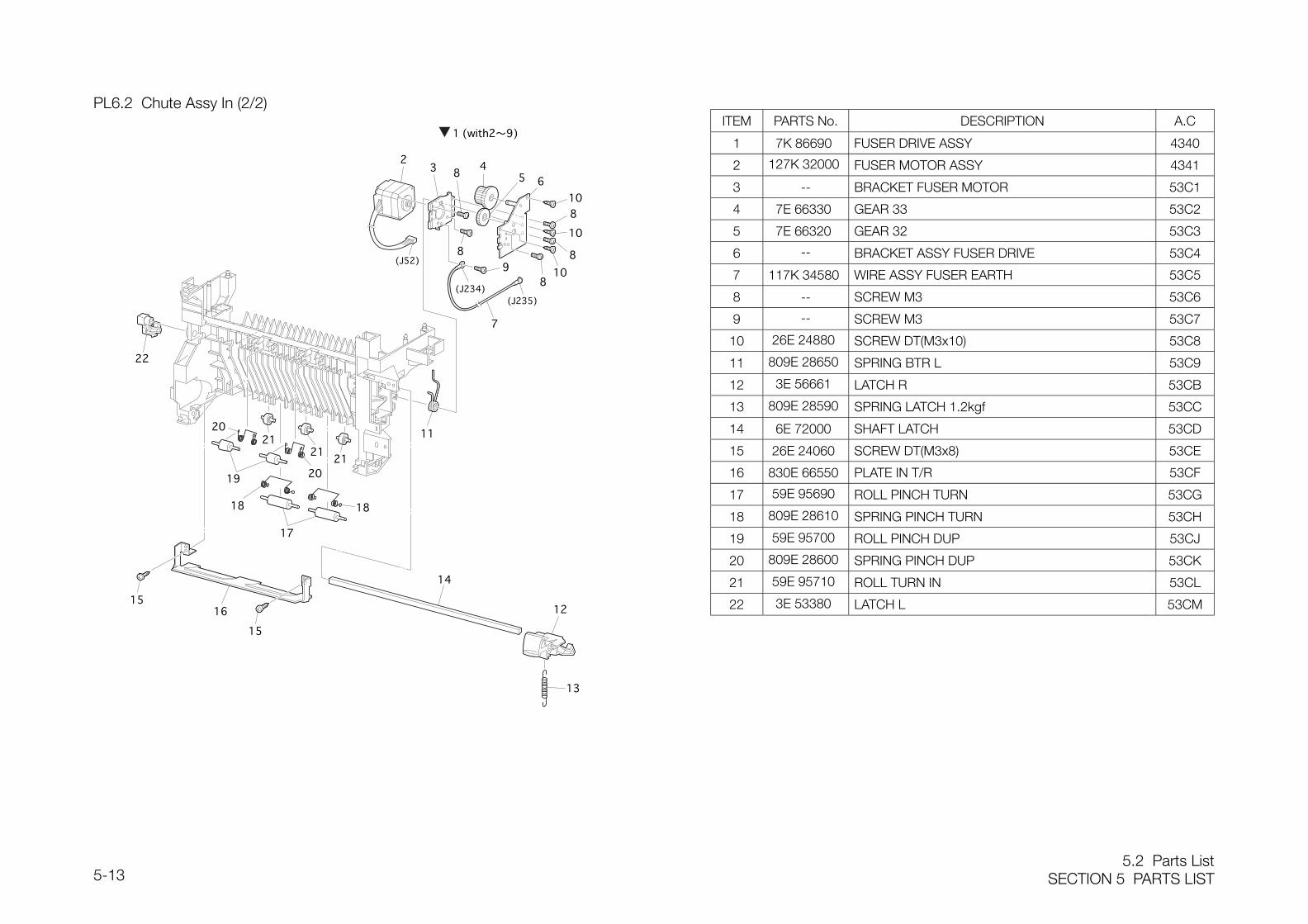
5.2 Parts ListSECTION 5 PARTS LIST5-13
PL6.2 Chute Assy In (2/2)ITEM PARTS No. DESCRIPTION A.C
1 7K 86690 FUSER DRIVE ASSY 4340
2 127K 32000 FUSER MOTOR ASSY 4341
3 -- BRACKET FUSER MOTOR 53C1
4 7E 66330 GEAR 33 53C2
5 7E 66320 GEAR 32 53C3
6 -- BRACKET ASSY FUSER DRIVE 53C4
7 117K 34580 WIRE ASSY FUSER EARTH 53C5
8 -- SCREW M3 53C6
9 -- SCREW M3 53C7
10 26E 24880 SCREW DT(M3x10) 53C8
11 809E 28650 SPRING BTR L 53C9
12 3E 56661 LATCH R 53CB
13 809E 28590 SPRING LATCH 1.2kgf 53CC
14 6E 72000 SHAFT LATCH 53CD
15 26E 24060 SCREW DT(M3x8) 53CE
16 830E 66550 PLATE IN T/R 53CF
17 59E 95690 ROLL PINCH TURN 53CG
18 809E 28610 SPRING PINCH TURN 53CH
19 59E 95700 ROLL PINCH DUP 53CJ
20 809E 28600 SPRING PINCH DUP 53CK
21 59E 95710 ROLL TURN IN 53CL
22 3E 53380 LATCH L 53CM
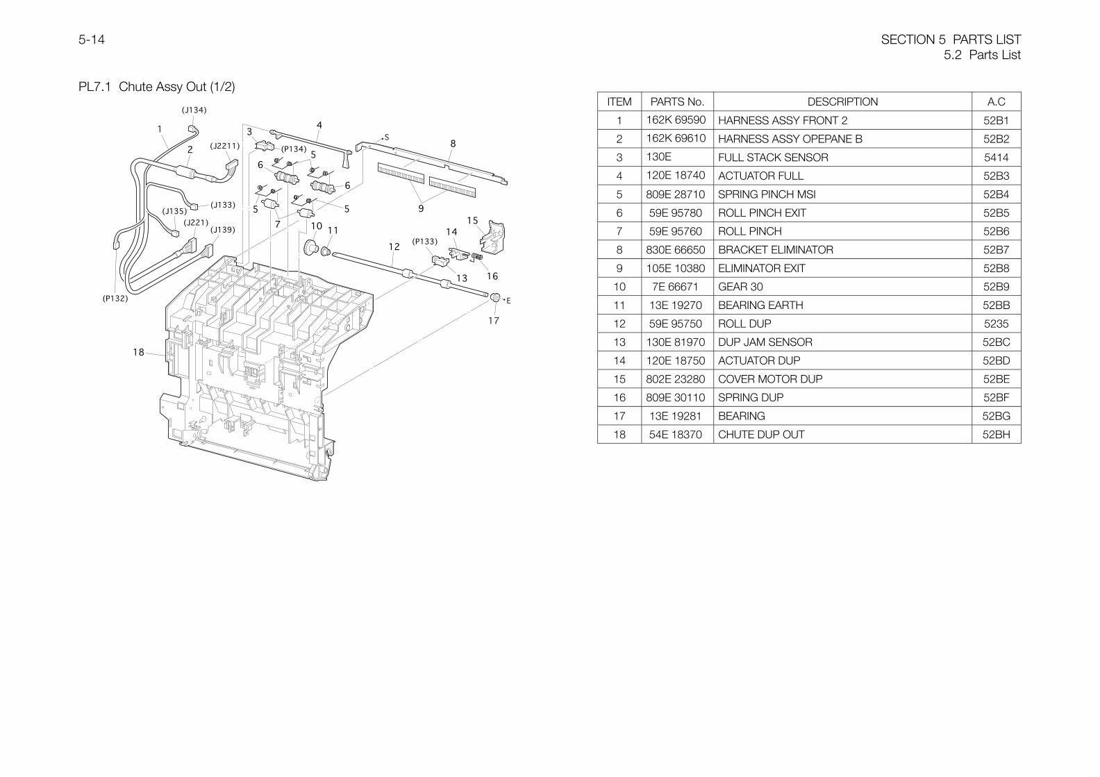
SECTION 5 PARTS LIST5.2 Parts List
5-14
PL7.1 Chute Assy Out (1/2)ITEM PARTS No. DESCRIPTION A.C
1 162K 69590 HARNESS ASSY FRONT 2 52B1
2 162K 69610 HARNESS ASSY OPEPANE B 52B2
3 130E FULL STACK SENSOR 5414
4 120E 18740 ACTUATOR FULL 52B3
5 809E 28710 SPRING PINCH MSI 52B4
6 59E 95780 ROLL PINCH EXIT 52B5
7 59E 95760 ROLL PINCH 52B6
8 830E 66650 BRACKET ELIMINATOR 52B7
9 105E 10380 ELIMINATOR EXIT 52B8
10 7E 66671 GEAR 30 52B9
11 13E 19270 BEARING EARTH 52BB
12 59E 95750 ROLL DUP 5235
13 130E 81970 DUP JAM SENSOR 52BC
14 120E 18750 ACTUATOR DUP 52BD
15 802E 23280 COVER MOTOR DUP 52BE
16 809E 30110 SPRING DUP 52BF
17 13E 19281 BEARING 52BG
18 54E 18370 CHUTE DUP OUT 52BH
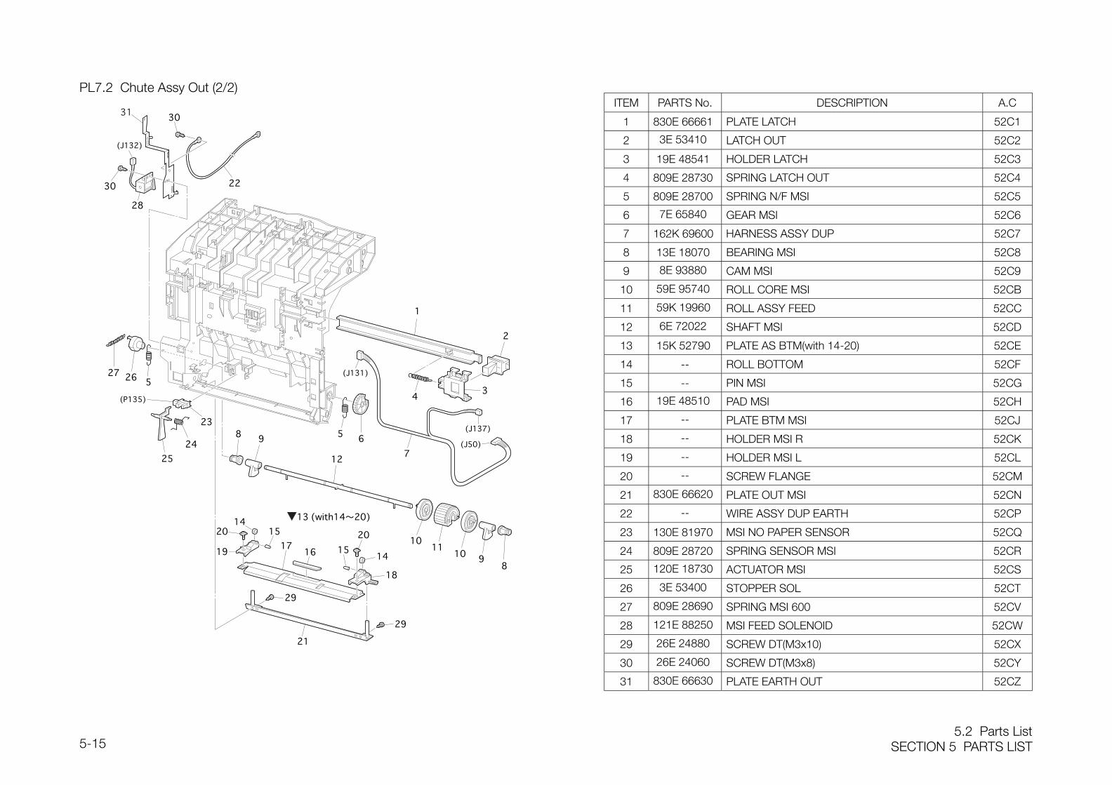
5.2 Parts ListSECTION 5 PARTS LIST5-15
PL7.2 Chute Assy Out (2/2)ITEM PARTS No. DESCRIPTION A.C
1 830E 66661 PLATE LATCH 52C1
2 3E 53410 LATCH OUT 52C2
3 19E 48541 HOLDER LATCH 52C3
4 809E 28730 SPRING LATCH OUT 52C4
5 809E 28700 SPRING N/F MSI 52C5
6 7E 65840 GEAR MSI 52C6
7 162K 69600 HARNESS ASSY DUP 52C7
8 13E 18070 BEARING MSI 52C8
9 8E 93880 CAM MSI 52C9
10 59E 95740 ROLL CORE MSI 52CB
11 59K 19960 ROLL ASSY FEED 52CC
12 6E 72022 SHAFT MSI 52CD
13 15K 52790 PLATE AS BTM(with 14-20) 52CE
14 -- ROLL BOTTOM 52CF
15 -- PIN MSI 52CG
16 19E 48510 PAD MSI 52CH
17 -- PLATE BTM MSI 52CJ
18 -- HOLDER MSI R 52CK
19 -- HOLDER MSI L 52CL
20 -- SCREW FLANGE 52CM
21 830E 66620 PLATE OUT MSI 52CN
22 -- WIRE ASSY DUP EARTH 52CP
23 130E 81970 MSI NO PAPER SENSOR 52CQ
24 809E 28720 SPRING SENSOR MSI 52CR
25 120E 18730 ACTUATOR MSI 52CS
26 3E 53400 STOPPER SOL 52CT
27 809E 28690 SPRING MSI 600 52CV
28 121E 88250 MSI FEED SOLENOID 52CW
29 26E 24880 SCREW DT(M3x10) 52CX
30 26E 24060 SCREW DT(M3x8) 52CY
31 830E 66630 PLATE EARTH OUT 52CZ
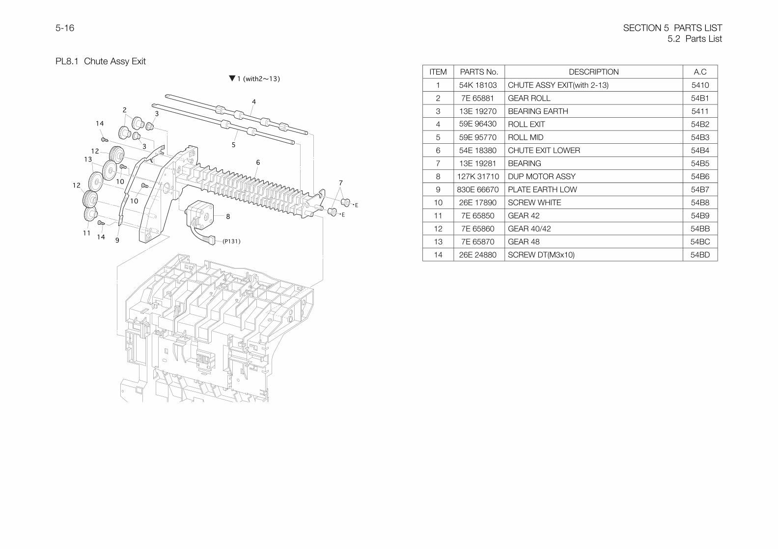
SECTION 5 PARTS LIST5.2 Parts List
5-16
PL8.1 Chute Assy ExitITEM PARTS No. DESCRIPTION A.C
1 54K 18103 CHUTE ASSY EXIT(with 2-13) 5410
2 7E 65881 GEAR ROLL 54B1
3 13E 19270 BEARING EARTH 5411
4 59E 96430 ROLL EXIT 54B2
5 59E 95770 ROLL MID 54B3
6 54E 18380 CHUTE EXIT LOWER 54B4
7 13E 19281 BEARING 54B5
8 127K 31710 DUP MOTOR ASSY 54B6
9 830E 66670 PLATE EARTH LOW 54B7
10 26E 17890 SCREW WHITE 54B8
11 7E 65850 GEAR 42 54B9
12 7E 65860 GEAR 40/42 54BB
13 7E 65870 GEAR 48 54BC
14 26E 24880 SCREW DT(M3x10) 54BD
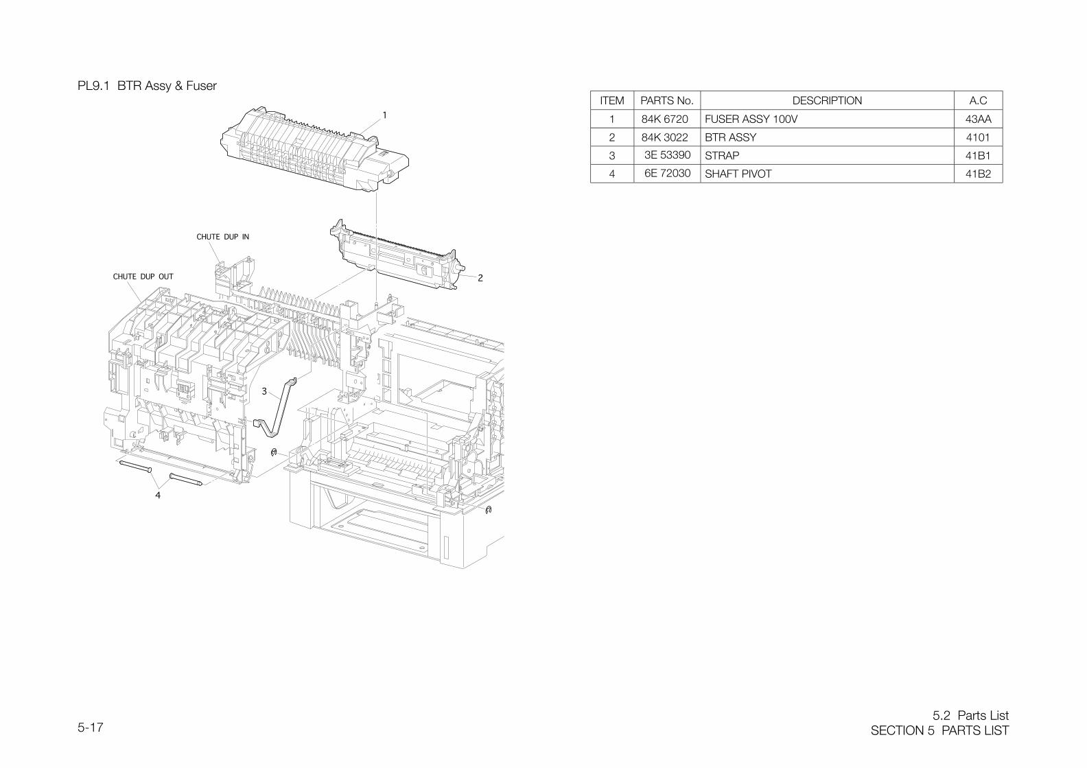
5.2 Parts ListSECTION 5 PARTS LIST5-17
PL9.1 BTR Assy & FuserITEM PARTS No. DESCRIPTION A.C
1 84K 6720 FUSER ASSY 100V 43AA
2 84K 3022 BTR ASSY 4101
3 3E 53390 STRAP 41B1
4 6E 72030 SHAFT PIVOT 41B2
SECTION 5 PARTS LIST5.2 Parts List
5-18
PL10.1 RegistrationITEM PARTS No. DESCRIPTION A.C
1 54K 20533 CHUTE REGI ST(with 2-22) 5310
2 7E 67420 GEAR REGI RUBBER 53D1
3 7E 67430 GEAR REGI METAL 53D2
4 13E 19270 BEARING EARTH 53D3
5 26E 24060 SCREW DT(M3xL8) 53D4
6 830E 70650 PLATE SIDE REGI 53D5
7 13E 19260 BEARING METAL L 53D6
8 9E 70960 SPRING REGI R/L 53D7
9 59E 96420 ROLL REGI METAL 5311
10 59E 96410 ROLL REGI RUBBER 53D8
11 13E 19250 BEARING METAL R 53D9
12 121E 88240 REGI CLUTCH 5312
13 13E 19281 BEARING 53DB
14 54E 18951 CHUTE REGI 53DC
15 19E 50500 HOLDER SENSOR OHP 53DD
16 130E 85330 OHP SENSOR 42DE
17 162K 69660 HARNESS ASSY OHP 53DF
18 26E 77680 STUD PLUNGER D/EARTH 53DG
19 809E 28580 SPRING DRUM EARTH 53DH
20 130E 81970 REGI SENSOR 5313
21 120E 20680 ACTUATOR REGI 53DJ
22 809E 34580 SPRING SENSOR REGI 53DK
23 -- HOUSING ASSY ELEC 53DL
5.2 Parts ListSECTION 5 PARTS LIST5-19
PL11.1 XerographicsITEM PARTS No. DESCRIPTION A.C
1 62K 10860 ROS ASSY 1310
2 809E 28560 SPRING ROS 13B1
3 84K 3015 PHD ASSY 45AA
4 802K 24821 HSG ASSY BIAS 45B1
5 26E 77670 STUD PLUNGER 45B2
6 26E 77690 SCREW DT(M4x16) 45B3
7 26E 24880 SCREW DT(M3x10) 45B4
8 892E 52850 LABEL IN.PHD 45B5
SECTION 5 PARTS LIST5.2 Parts List
5-20
PL12.1 TCRU Assy (1/3)
PL 12.3
PL 12.2
ITEM PARTS No. DESCRIPTION A.C
1 -- TONER CARTRIDGE(Y) 4011
2 -- TONER CARTRIDGE(M) 40B1
3 -- TONER CARTRIDGE(C) 40B2
4 -- TONER CARTRIDGE(K) 40B3
5 26E 25060 SCREW DT(M3x6) 40B4
6 162K 69670 HARNESS ASSY TNR 40B5
7 26E 24880 SCREW DT(M3x10) 40B6
8 160K 83190 EEPROM PWB 40B7
9 105K 19520 SUB HVPS 7320
5.2 Parts ListSECTION 5 PARTS LIST5-21
PL12.2 TCRU Assy (2/3)ITEM PARTS No. DESCRIPTION A.C
1 -- HOLDER TONER ASSY(Y)(with 2-30) 40101 -- HOLDER TONER ASSY(M)(with 2-30) 40C11 -- HOLDER TONER ASSY(C)(with 2-30) 40C21 -- HOLDER TONER ASSY(K)(with 2-30) 40C32 802E 26970 TONER HOUSING(Y) 40C42 802E 26980 TONER HOUSING(M) 40C52 802E 26990 TONER HOUSING(C) 40C62 802E 27000 TONER HOUSING(K) 40C73 802K 34920 COVER ASSY HOLDER 40C84 35E 62940 SEAL HOLDER 40C95 13E 19740 BEARING AGITATOR L 40CB6 33K 94050 AGITATOR ASSY 40CC7 35E 59590 SEAL OIL 40CD8 13E 19750 BEARING AGITATOR 40CE9 5E 16280 COLLAR AGITATOR 40CF
10 7E 71080 GEAR AGITATOR 40CG11 7E 71070 GEAR AUGER 40CH12 13E 19730 BEARING AUGER 40CJ13 35E 62920 SEAL OIL φ4 40CK14 59E 97010 AUGER ASSY(Y) 401314 59E 97020 AUGER ASSY(M) 40CL14 59E 97030 AUGER ASSY(C) 40CM14 59E 97040 AUGER ASSY(K) 40CN15 7E 71090 GEAR TCRU 40CP16 7E 71120 GEAR IDLER 2 40CQ17 7E 71110 GEAR IDLER 1 40CR18 830E 79080 BRACKET MOTOR 40CS19 26E 24880 SCREW-DT(M3x10) 40CT20 15E 77140 PLATE MOTOR 40CV21 127K 33050 TONER MOTOR ASSY 40CW22 830E 80290 BRACKET SRG NZZL 40CX23 809E 34830 SPRING NOZZLE 40CY24 21E 97760 CAP NOZZLE 40CZ25 52E 94960 NOZZLE MAIN 40D126 52E 94910 PIPE AUGER 1(Y) 40D226 52E 94920 PIPE AUGER 2(M) 40D326 52E 94930 PIPE AUGER 3(C) 40D426 52E 94940 PIPE AUGER 4(K) 40D527 26E 24060 SCREW-DT(M3x8) 40D628 130E 85200 LOW TONER SENSOR 40D729 -- KEY TCRU 1(Y) 40D829 -- KEY TCRU 2(M) 40D929 -- KEY TCRU 3(C) 40DB29 -- KEY TCRU 4(K) 40DC30 110K 11250 TCRU SWITCH ASSY 40DD
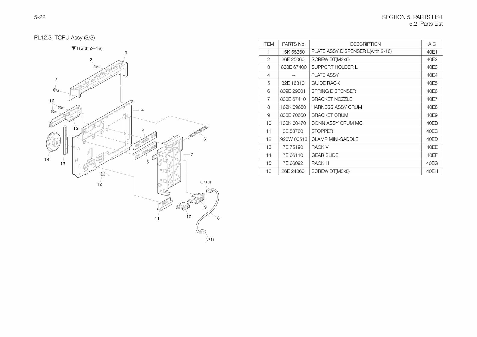
SECTION 5 PARTS LIST5.2 Parts List
5-22
PL12.3 TCRU Assy (3/3)ITEM PARTS No. DESCRIPTION A.C
1 15K 55360 PLATE ASSY DISPENSER L(with 2-16) 40E1
2 26E 25060 SCREW DT(M3x6) 40E2
3 830E 67400 SUPPORT HOLDER L 40E3
4 -- PLATE ASSY 40E4
5 32E 16310 GUIDE RACK 40E5
6 809E 29001 SPRING DISPENSER 40E6
7 830E 67410 BRACKET NOZZLE 40E7
8 162K 69680 HARNESS ASSY CRUM 40E8
9 830E 70660 BRACKET CRUM 40E9
10 130K 60470 CONN ASSY CRUM MC 40EB
11 3E 53760 STOPPER 40EC
12 920W 00513 CLAMP MINI-SADDLE 40ED
13 7E 75190 RACK V 40EE
14 7E 66110 GEAR SLIDE 40EF
15 7E 66092 RACK H 40EG
16 26E 24060 SCREW DT(M3x8) 40EH
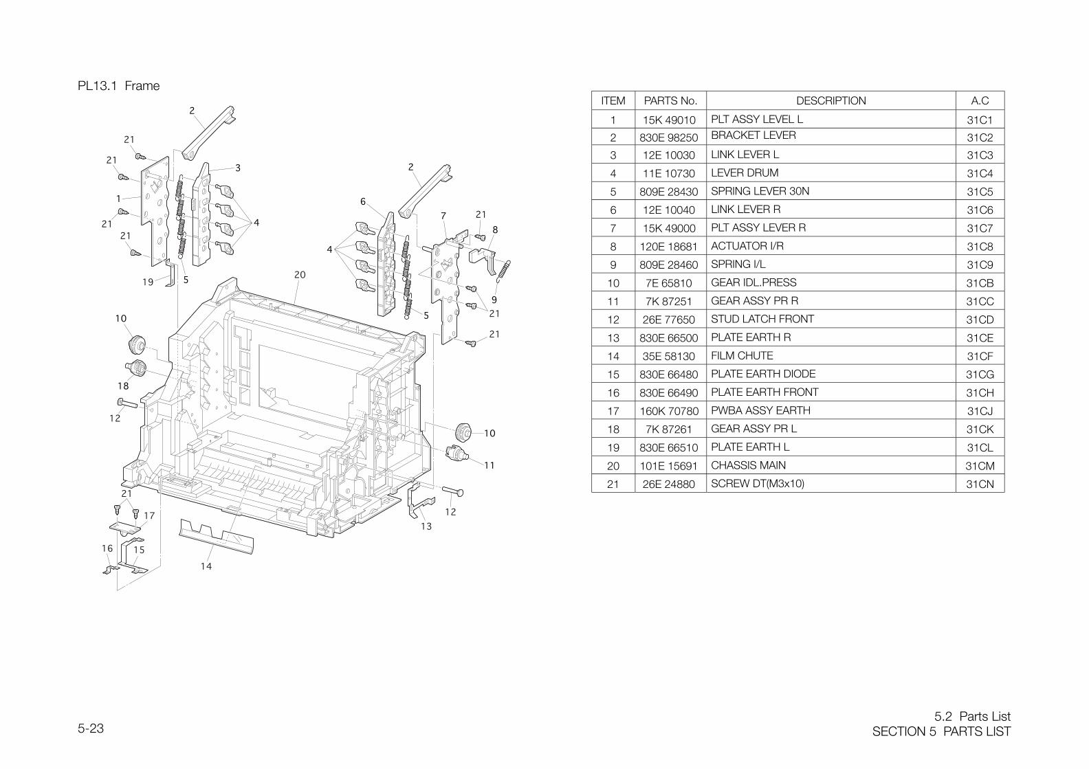
5.2 Parts ListSECTION 5 PARTS LIST5-23
PL13.1 FrameITEM PARTS No. DESCRIPTION A.C
1 15K 49010 PLT ASSY LEVEL L 31C1
2 830E 98250 BRACKET LEVER 31C2
3 12E 10030 LINK LEVER L 31C3
4 11E 10730 LEVER DRUM 31C4
5 809E 28430 SPRING LEVER 30N 31C5
6 12E 10040 LINK LEVER R 31C6
7 15K 49000 PLT ASSY LEVER R 31C7
8 120E 18681 ACTUATOR I/R 31C8
9 809E 28460 SPRING I/L 31C9
10 7E 65810 GEAR IDL.PRESS 31CB
11 7K 87251 GEAR ASSY PR R 31CC
12 26E 77650 STUD LATCH FRONT 31CD
13 830E 66500 PLATE EARTH R 31CE
14 35E 58130 FILM CHUTE 31CF
15 830E 66480 PLATE EARTH DIODE 31CG
16 830E 66490 PLATE EARTH FRONT 31CH
17 160K 70780 PWBA ASSY EARTH 31CJ
18 7K 87261 GEAR ASSY PR L 31CK
19 830E 66510 PLATE EARTH L 31CL
20 101E 15691 CHASSIS MAIN 31CM
21 26E 24880 SCREW DT(M3x10) 31CN
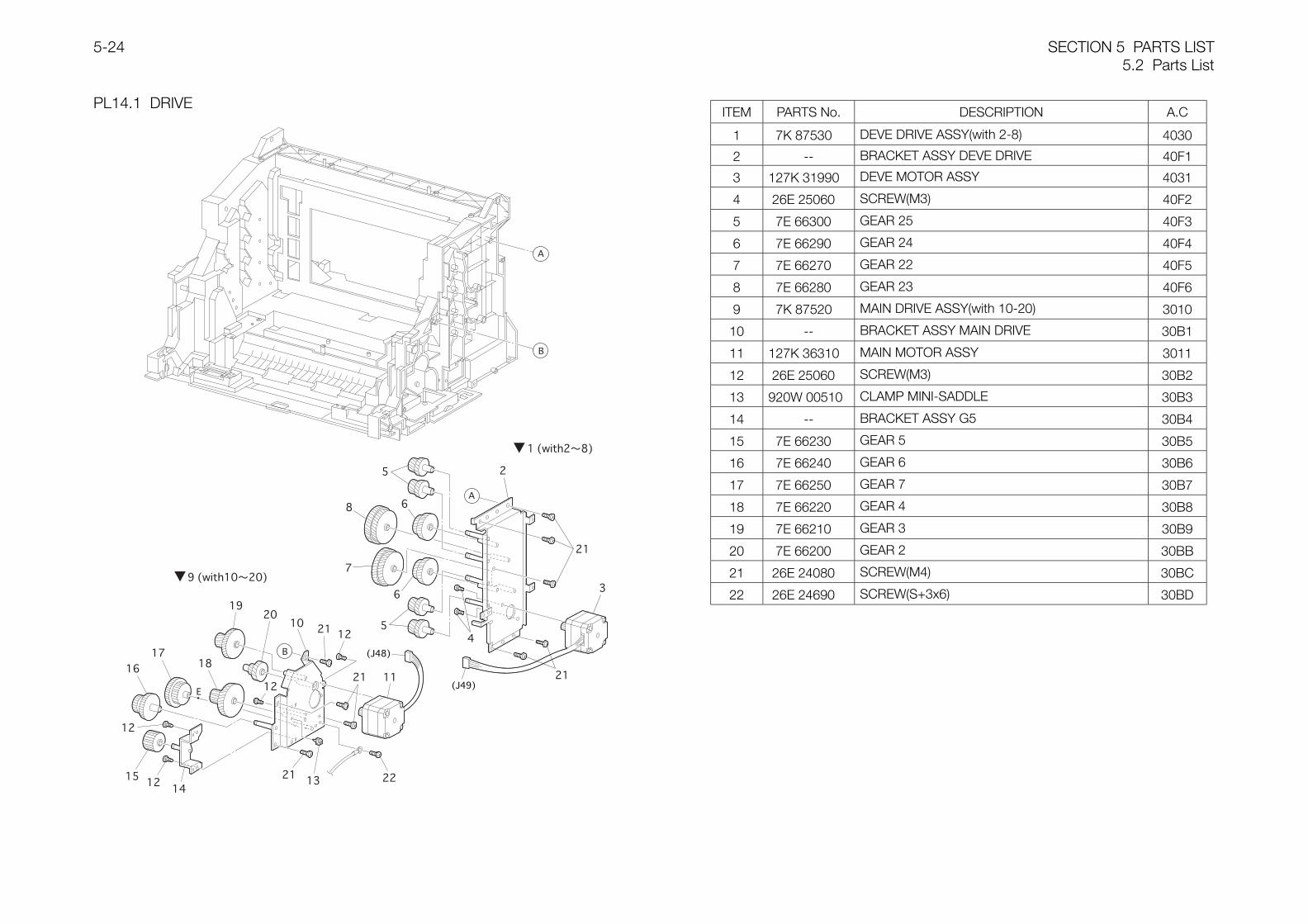
SECTION 5 PARTS LIST5.2 Parts List
5-24
PL14.1 DRIVEITEM PARTS No. DESCRIPTION A.C
1 7K 87530 DEVE DRIVE ASSY(with 2-8) 4030
2 -- BRACKET ASSY DEVE DRIVE 40F1
3 127K 31990 DEVE MOTOR ASSY 4031
4 26E 25060 SCREW(M3) 40F2
5 7E 66300 GEAR 25 40F3
6 7E 66290 GEAR 24 40F4
7 7E 66270 GEAR 22 40F5
8 7E 66280 GEAR 23 40F6
9 7K 87520 MAIN DRIVE ASSY(with 10-20) 3010
10 -- BRACKET ASSY MAIN DRIVE 30B1
11 127K 36310 MAIN MOTOR ASSY 3011
12 26E 25060 SCREW(M3) 30B2
13 920W 00510 CLAMP MINI-SADDLE 30B3
14 -- BRACKET ASSY G5 30B4
15 7E 66230 GEAR 5 30B5
16 7E 66240 GEAR 6 30B6
17 7E 66250 GEAR 7 30B7
18 7E 66220 GEAR 4 30B8
19 7E 66210 GEAR 3 30B9
20 7E 66200 GEAR 2 30BB
21 26E 24080 SCREW(M4) 30BC
22 26E 24690 SCREW(S+3x6) 30BD
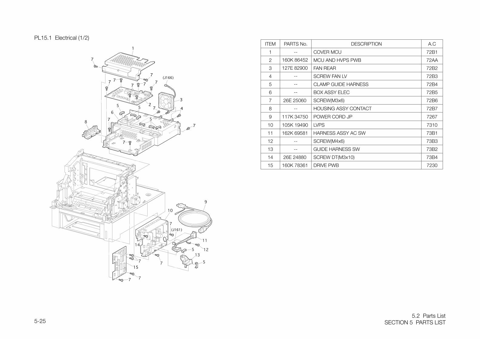
5.2 Parts ListSECTION 5 PARTS LIST5-25
PL15.1 Electrical (1/2)ITEM PARTS No. DESCRIPTION A.C
1 -- COVER MCU 72B1
2 160K 86452 MCU AND HVPS PWB 72AA
3 127E 82900 FAN REAR 72B2
4 -- SCREW FAN LV 72B3
5 -- CLAMP GUIDE HARNESS 72B4
6 -- BOX ASSY ELEC 72B5
7 26E 25060 SCREW(M3x6) 72B6
8 -- HOUSING ASSY CONTACT 72B7
9 117K 34750 POWER CORD JP 7267
10 105K 19490 LVPS 7310
11 162K 69581 HARNESS ASSY AC SW 73B1
12 -- SCREW(M4x6) 73B3
13 -- GUIDE HARNESS SW 73B2
14 26E 24880 SCREW DT(M3x10) 73B4
15 160K 78361 DRIVE PWB 7230
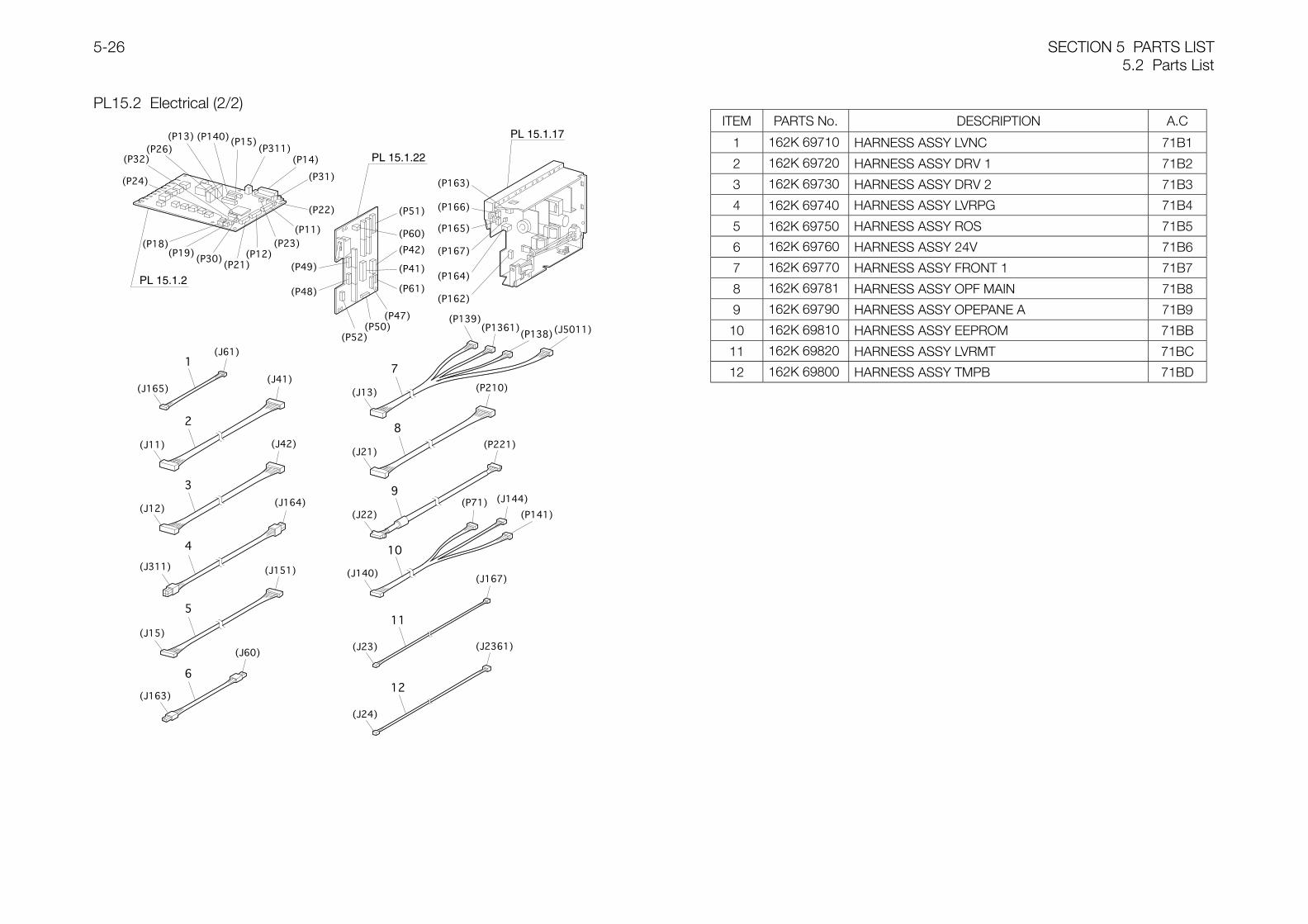
SECTION 5 PARTS LIST5.2 Parts List
5-26
PL15.2 Electrical (2/2)
PL 15.1.2
PL 15.1.22
PL 15.1.17ITEM PARTS No. DESCRIPTION A.C
1 162K 69710 HARNESS ASSY LVNC 71B1
2 162K 69720 HARNESS ASSY DRV 1 71B2
3 162K 69730 HARNESS ASSY DRV 2 71B3
4 162K 69740 HARNESS ASSY LVRPG 71B4
5 162K 69750 HARNESS ASSY ROS 71B5
6 162K 69760 HARNESS ASSY 24V 71B6
7 162K 69770 HARNESS ASSY FRONT 1 71B7
8 162K 69781 HARNESS ASSY OPF MAIN 71B8
9 162K 69790 HARNESS ASSY OPEPANE A 71B9
10 162K 69810 HARNESS ASSY EEPROM 71BB
11 162K 69820 HARNESS ASSY LVRMT 71BC
12 162K 69800 HARNESS ASSY TMPB 71BD
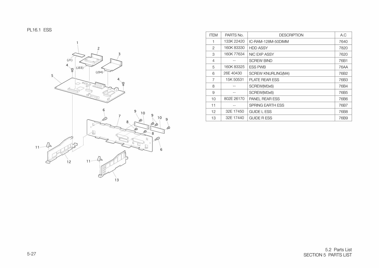
5.2 Parts ListSECTION 5 PARTS LIST5-27
PL16.1 ESSITEM PARTS No. DESCRIPTION A.C
1 133K 22420 IC-RAM-128M-50DIMM 7640
2 160K 83330 HDD ASSY 7820
3 160K 77634 NIC EXP ASSY 7620
4 -- SCREW BIND 76B1
5 160K 83325 ESS PWB 76AA
6 26E 40430 SCREW KNURLING(M4) 76B2
7 15K 50531 PLATE REAR ESS 76B3
8 -- SCREW(M3x6) 76B4
9 -- SCREW(M3x6) 76B5
10 802E 26170 PANEL REAR ESS 76B6
11 -- SPRING EARTH ESS 76B7
12 32E 17450 GUIDE L ESS 76B8
13 32E 17440 GUIDE R ESS 76B9
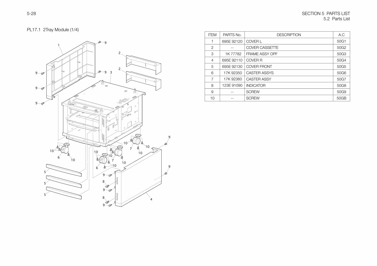
SECTION 5 PARTS LIST5.2 Parts List
5-28
PL17.1 2Tray Module (1/4)ITEM PARTS No. DESCRIPTION A.C
1 695E 92120 COVER L 50G1
2 -- COVER CASSETTE 50G2
3 1K 77782 FRAME ASSY OPF 50G3
4 695E 92110 COVER R 50G4
5 695E 92130 COVER FRONT 50G5
6 17K 92350 CASTER ASSYS 50G6
7 17K 92360 CASTER ASSY 50G7
8 123E 91090 INDICATOR 50G8
9 -- SCREW 50G9
10 -- SCREW 50GB
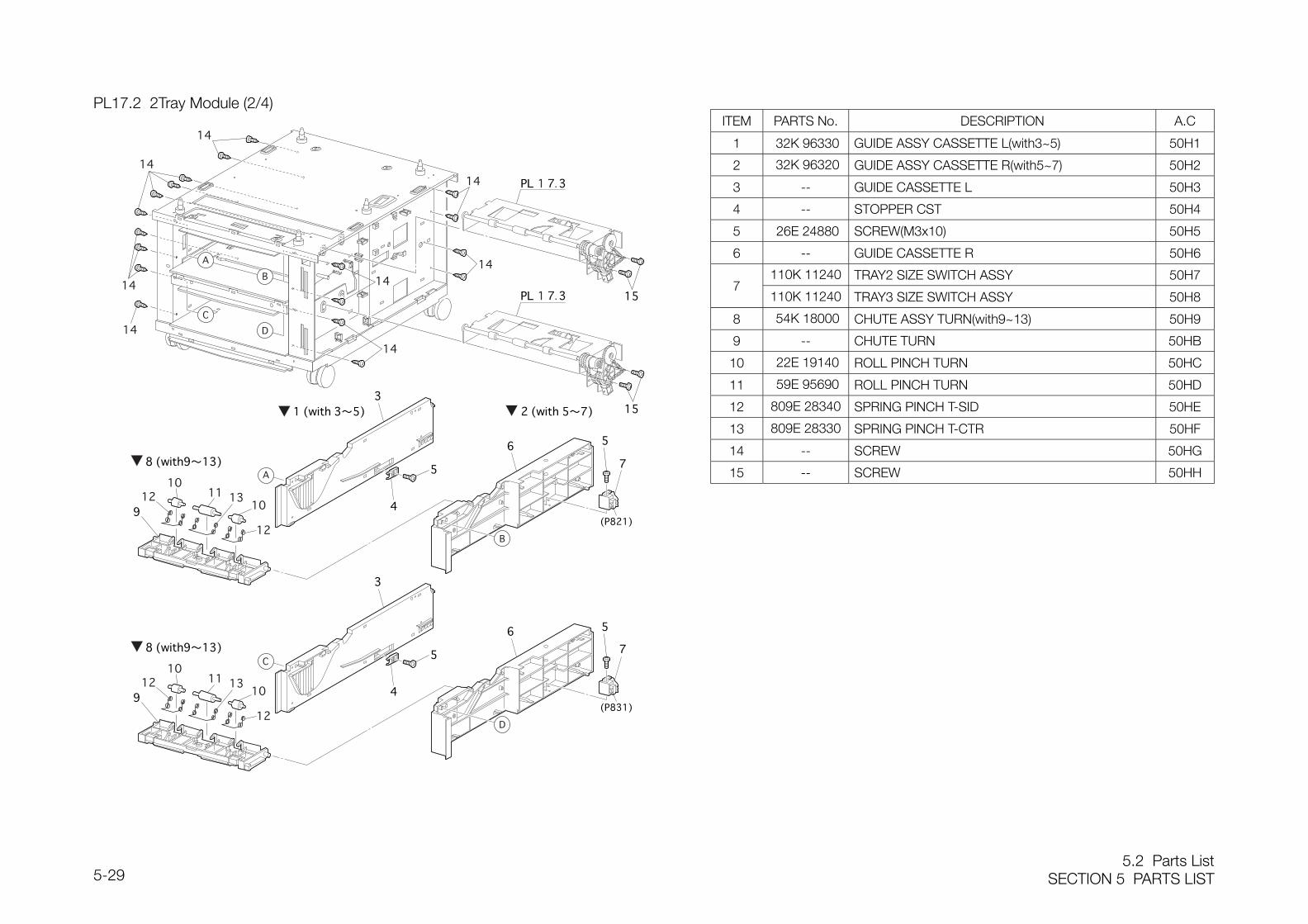
5.2 Parts ListSECTION 5 PARTS LIST5-29
PL17.2 2Tray Module (2/4)ITEM PARTS No. DESCRIPTION A.C
1 32K 96330 GUIDE ASSY CASSETTE L(with3~5) 50H1
2 32K 96320 GUIDE ASSY CASSETTE R(with5~7) 50H2
3 -- GUIDE CASSETTE L 50H3
4 -- STOPPER CST 50H4
5 26E 24880 SCREW(M3x10) 50H5
6 -- GUIDE CASSETTE R 50H6
110K 11240 TRAY2 SIZE SWITCH ASSY 50H77
110K 11240 TRAY3 SIZE SWITCH ASSY 50H8
8 54K 18000 CHUTE ASSY TURN(with9~13) 50H9
9 -- CHUTE TURN 50HB
10 22E 19140 ROLL PINCH TURN 50HC
11 59E 95690 ROLL PINCH TURN 50HD
12 809E 28340 SPRING PINCH T-SID 50HE
13 809E 28330 SPRING PINCH T-CTR 50HF
14 -- SCREW 50HG
15 -- SCREW 50HH
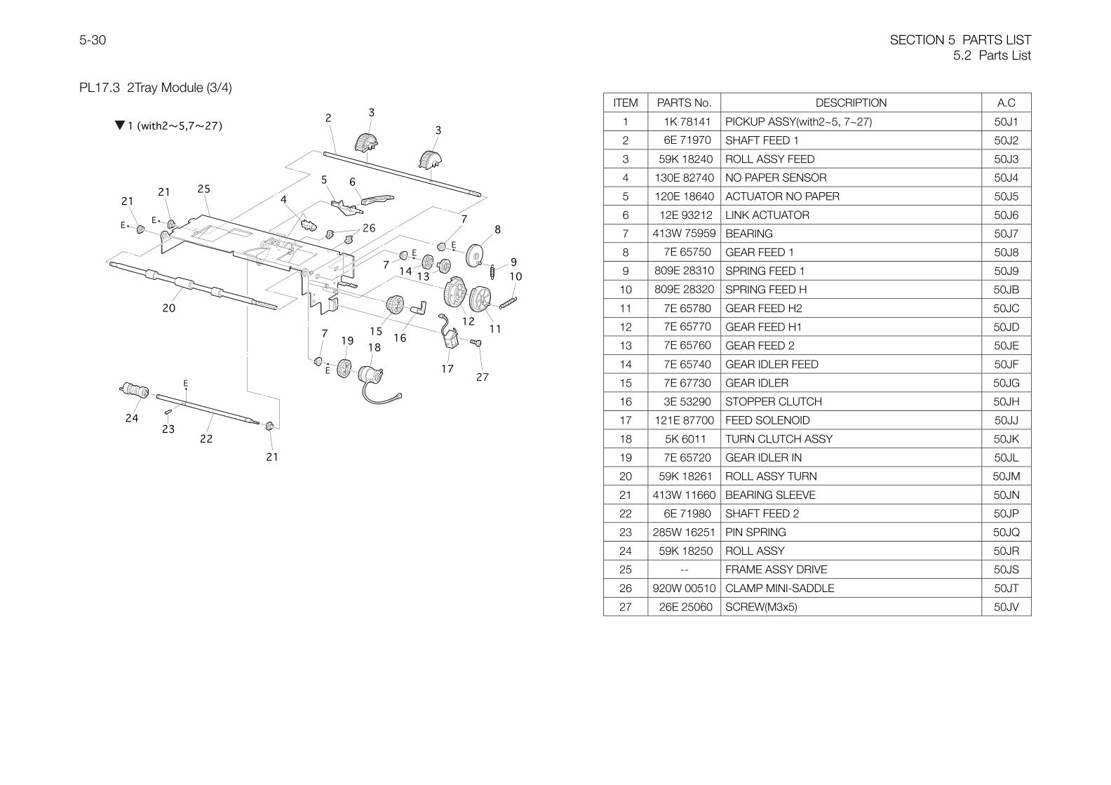
SECTION 5 PARTS LIST5.2 Parts List
5-30
PL17.3 2Tray Module (3/4)ITEM PARTS No. DESCRIPTION A.C
1 1K 78141 PICKUP ASSY(with2~5, 7~27) 50J1
2 6E 71970 SHAFT FEED 1 50J2
3 59K 18240 ROLL ASSY FEED 50J3
4 130E 82740 NO PAPER SENSOR 50J4
5 120E 18640 ACTUATOR NO PAPER 50J5
6 12E 93212 LINK ACTUATOR 50J6
7 413W 75959 BEARING 50J7
8 7E 65750 GEAR FEED 1 50J8
9 809E 28310 SPRING FEED 1 50J9
10 809E 28320 SPRING FEED H 50JB
11 7E 65780 GEAR FEED H2 50JC
12 7E 65770 GEAR FEED H1 50JD
13 7E 65760 GEAR FEED 2 50JE
14 7E 65740 GEAR IDLER FEED 50JF
15 7E 67730 GEAR IDLER 50JG
16 3E 53290 STOPPER CLUTCH 50JH
17 121E 87700 FEED SOLENOID 50JJ
18 5K 6011 TURN CLUTCH ASSY 50JK
19 7E 65720 GEAR IDLER IN 50JL
20 59K 18261 ROLL ASSY TURN 50JM
21 413W 11660 BEARING SLEEVE 50JN
22 6E 71980 SHAFT FEED 2 50JP
23 285W 16251 PIN SPRING 50JQ
24 59K 18250 ROLL ASSY 50JR
25 -- FRAME ASSY DRIVE 50JS
26 920W 00510 CLAMP MINI-SADDLE 50JT
27 26E 25060 SCREW(M3x5) 50JV
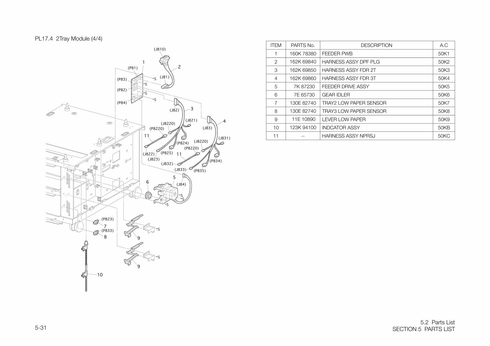
5.2 Parts ListSECTION 5 PARTS LIST5-31
PL17.4 2Tray Module (4/4)ITEM PARTS No. DESCRIPTION A.C
1 160K 78380 FEEDER PWB 50K1
2 162K 69840 HARNESS ASSY DPF PLG 50K2
3 162K 69850 HARNESS ASSY FDR 2T 50K3
4 162K 69860 HARNESS ASSY FDR 3T 50K4
5 7K 87230 FEEDER DRIVE ASSY 50K5
6 7E 65730 GEAR IDLER 50K6
7 130E 82740 TRAY2 LOW PAPER SENSOR 50K7
8 130E 82740 TRAY3 LOW PAPER SENSOR 50K8
9 11E 10890 LEVER LOW PAPER 50K9
10 123K 94100 INDCATOR ASSY 50KB
11 -- HARNESS ASSY NPRSJ 50KC
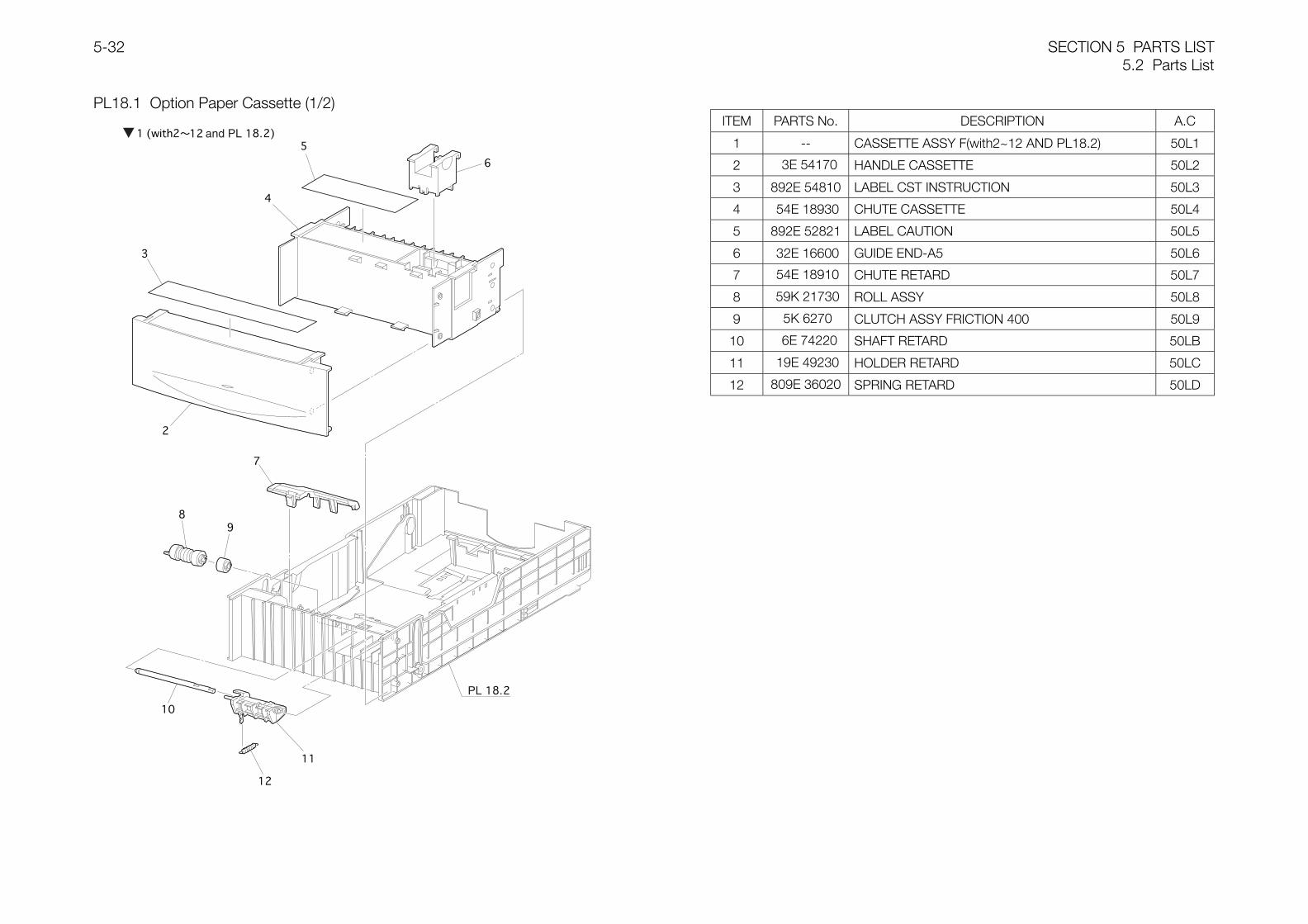
SECTION 5 PARTS LIST5.2 Parts List
5-32
PL18.1 Option Paper Cassette (1/2)ITEM PARTS No. DESCRIPTION A.C
1 -- CASSETTE ASSY F(with2~12 AND PL18.2) 50L1
2 3E 54170 HANDLE CASSETTE 50L2
3 892E 54810 LABEL CST INSTRUCTION 50L3
4 54E 18930 CHUTE CASSETTE 50L4
5 892E 52821 LABEL CAUTION 50L5
6 32E 16600 GUIDE END-A5 50L6
7 54E 18910 CHUTE RETARD 50L7
8 59K 21730 ROLL ASSY 50L8
9 5K 6270 CLUTCH ASSY FRICTION 400 50L9
10 6E 74220 SHAFT RETARD 50LB
11 19E 49230 HOLDER RETARD 50LC
12 809E 36020 SPRING RETARD 50LD
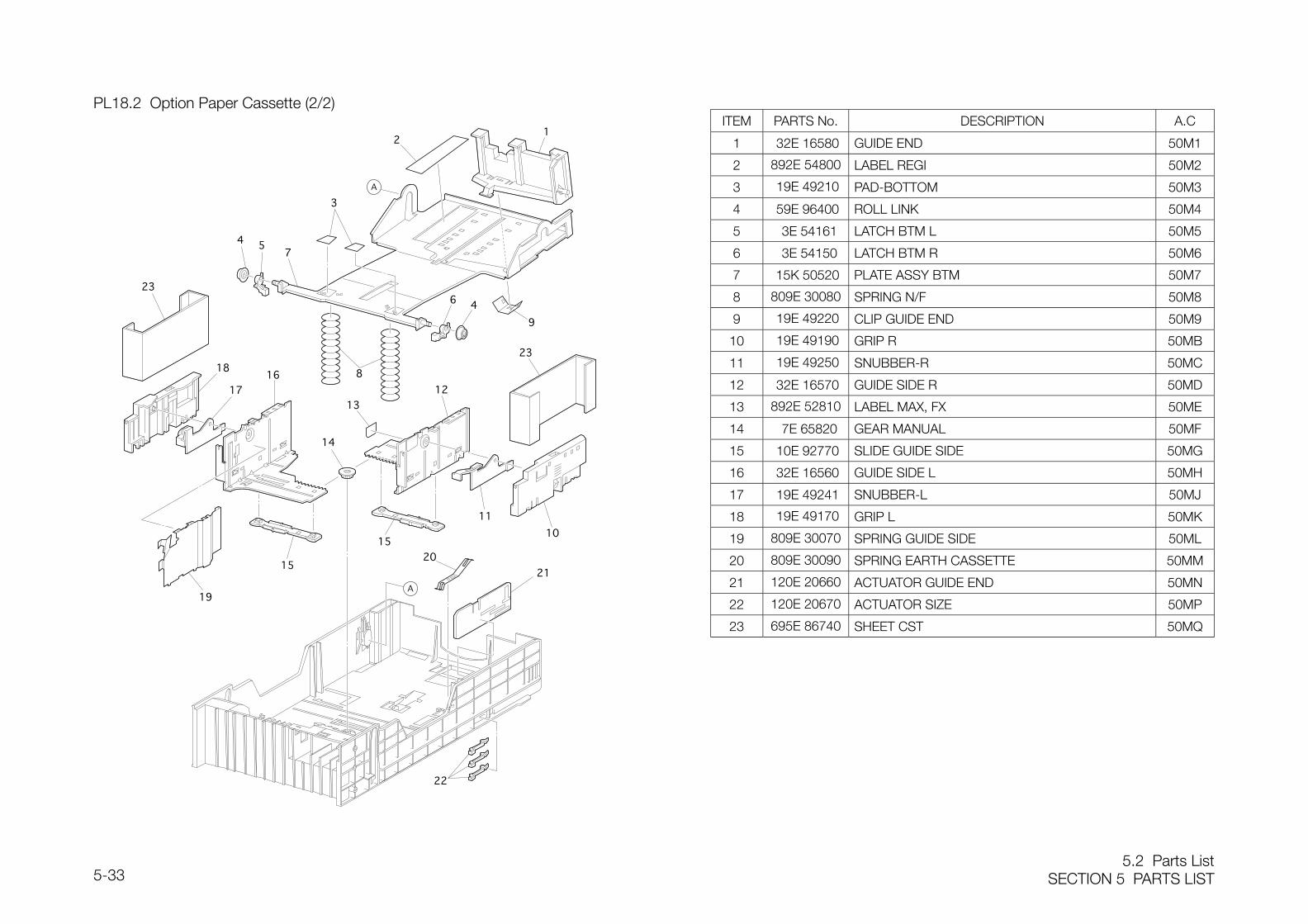
5.2 Parts ListSECTION 5 PARTS LIST5-33
PL18.2 Option Paper Cassette (2/2)ITEM PARTS No. DESCRIPTION A.C
1 32E 16580 GUIDE END 50M1
2 892E 54800 LABEL REGI 50M2
3 19E 49210 PAD-BOTTOM 50M3
4 59E 96400 ROLL LINK 50M4
5 3E 54161 LATCH BTM L 50M5
6 3E 54150 LATCH BTM R 50M6
7 15K 50520 PLATE ASSY BTM 50M7
8 809E 30080 SPRING N/F 50M8
9 19E 49220 CLIP GUIDE END 50M9
10 19E 49190 GRIP R 50MB
11 19E 49250 SNUBBER-R 50MC
12 32E 16570 GUIDE SIDE R 50MD
13 892E 52810 LABEL MAX, FX 50ME
14 7E 65820 GEAR MANUAL 50MF
15 10E 92770 SLIDE GUIDE SIDE 50MG
16 32E 16560 GUIDE SIDE L 50MH
17 19E 49241 SNUBBER-L 50MJ
18 19E 49170 GRIP L 50MK
19 809E 30070 SPRING GUIDE SIDE 50ML
20 809E 30090 SPRING EARTH CASSETTE 50MM
21 120E 20660 ACTUATOR GUIDE END 50MN
22 120E 20670 ACTUATOR SIZE 50MP
23 695E 86740 SHEET CST 50MQ
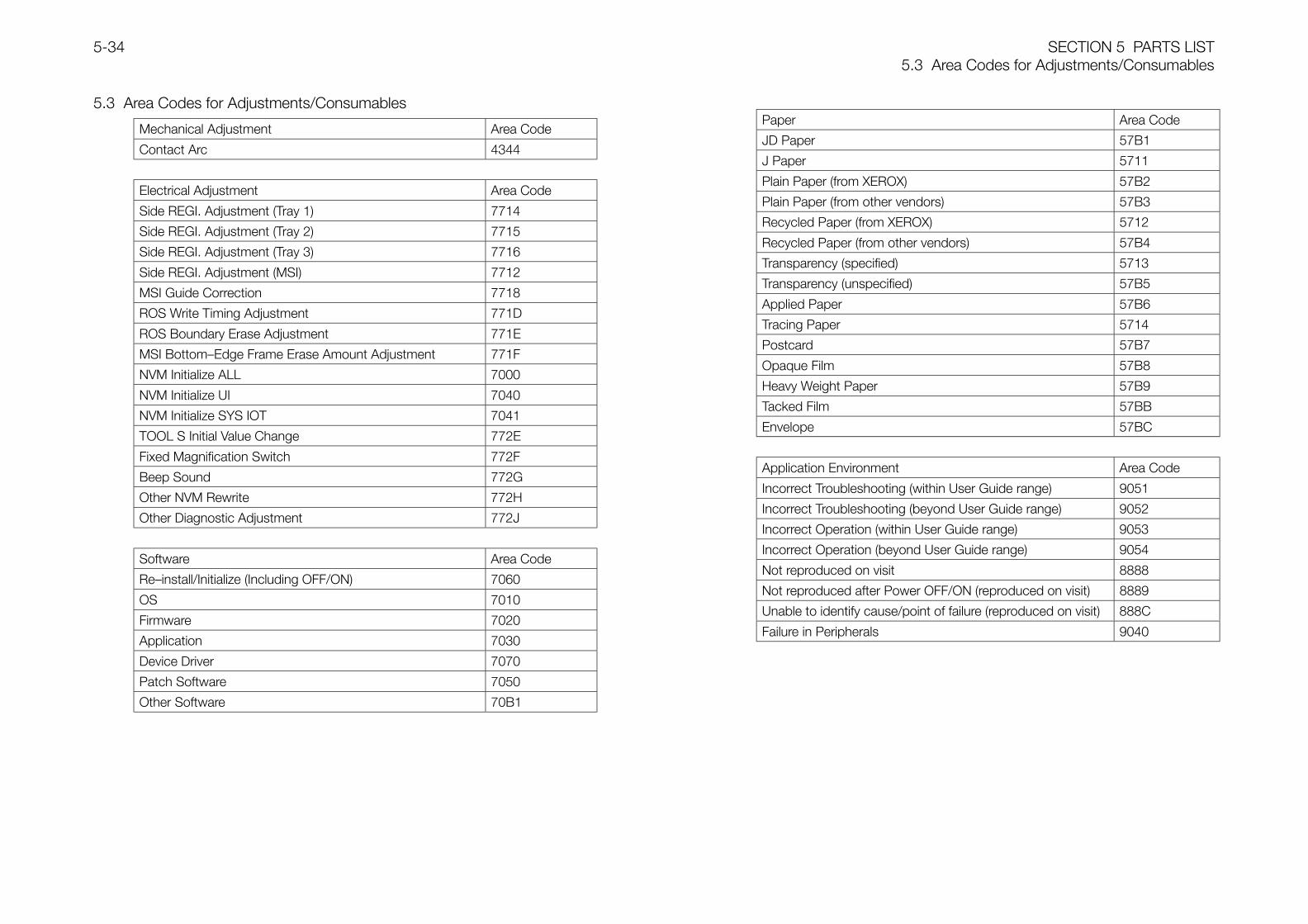
SECTION 5 PARTS LIST5.3 Area Codes for Adjustments/Consumables
5-34
5.3 Area Codes for Adjustments/Consumables
Mechanical Adjustment Area Code
Contact Arc 4344
Electrical Adjustment Area Code
Side REGI. Adjustment (Tray 1) 7714
Side REGI. Adjustment (Tray 2) 7715
Side REGI. Adjustment (Tray 3) 7716
Side REGI. Adjustment (MSI) 7712
MSI Guide Correction 7718
ROS Write Timing Adjustment 771D
ROS Boundary Erase Adjustment 771E
MSI Bottom—Edge Frame Erase Amount Adjustment 771F
NVM Initialize ALL 7000
NVM Initialize UI 7040
NVM Initialize SYS IOT 7041
TOOL S Initial Value Change 772E
Fixed Magnification Switch 772F
Beep Sound 772G
Other NVM Rewrite 772H
Other Diagnostic Adjustment 772J
Software Area Code
Re—install/Initialize (Including OFF/ON) 7060
OS 7010
Firmware 7020
Application 7030
Device Driver 7070
Patch Software 7050
Other Software 70B1
Paper Area Code
JD Paper 57B1
J Paper 5711
Plain Paper (from XEROX) 57B2
Plain Paper (from other vendors) 57B3
Recycled Paper (from XEROX) 5712
Recycled Paper (from other vendors) 57B4
Transparency (specified) 5713
Transparency (unspecified) 57B5
Applied Paper 57B6
Tracing Paper 5714
Postcard 57B7
Opaque Film 57B8
Heavy Weight Paper 57B9
Tacked Film 57BB
Envelope 57BC
Application Environment Area Code
Incorrect Troubleshooting (within User Guide range) 9051
Incorrect Troubleshooting (beyond User Guide range) 9052
Incorrect Operation (within User Guide range) 9053
Incorrect Operation (beyond User Guide range) 9054
Not reproduced on visit 8888
Not reproduced after Power OFF/ON (reproduced on visit) 8889
Unable to identify cause/point of failure (reproduced on visit) 888C
Failure in Peripherals 9040

SECTION 6 GENERAL
ContentsSECTION 6 GENERAL6-1
Contents
6.1 Specifications .................................................................................................... 3
6.1.1 Product Names/Product Code/FWSS Code ................................................ 3
6.1.2 Printer Dimensions and Weight .................................................................... 3
6.1.3 Installation Space......................................................................................... 3
6.1.4 Printer System Configuration........................................................................ 3
6.1.4.1 Printer Overview .................................................................................... 3
6.1.4.2 IOT Feature Overview ............................................................................ 4
6.1.4.3 Standard ESS Configuration .................................................................. 4
6.1.5 List of Options ............................................................................................. 5
6.1.6 Documentation ............................................................................................ 5
6.1.7 System Characteristics ................................................................................ 5
6.1.7.1 Operating Modes................................................................................... 5
6.1.7.2 Throughput............................................................................................ 6
6.1.7.3 FPOT..................................................................................................... 6
6.1.7.4 Continuous Print Speed......................................................................... 6
6.1.7.5 Warmup Time........................................................................................ 6
6.1.8 Print Function .............................................................................................. 6
6.1.8.1 Image Area ............................................................................................ 6
6.1.8.2 Printer Fonts (Japanese: 2 styles, English: 13 styles) .............................. 6
6.1.8.3 True Type Fonts ..................................................................................... 7
6.1.9 Image Processing Features.......................................................................... 7
6.1.9.1 Specify Color/Black & White .................................................................. 7
6.1.9.2 Paper Type Selection ............................................................................. 7
6.1.9.3 EconoMode........................................................................................... 7
6.1.9.4 Color Matching ...................................................................................... 7
6.1.9.5 Image Settings....................................................................................... 7
6.1.9.6 Color Balance........................................................................................ 7
6.1.9.7 Auto Image Quality Adjustment ..............................................................7
6.1.9.8 Document Types....................................................................................7
6.1.9.9 Profile Settings.......................................................................................8
6.1.10 Additional Image Features ..........................................................................8
6.1.10.1 Watermark (Windows version only) .......................................................8
6.1.11 Page Layout Features ................................................................................8
6.1.11.1 180° Rotation Print ..............................................................................8
6.1.11.2 Reduction/Enlargement (Zoom)............................................................8
6.1.11.3 N-Up ...................................................................................................8
6.1.11.4 Margin Shift .........................................................................................8
6.1.11.5 Image Repeat ......................................................................................8
6.1.11.6 Booklet Printing (Windows version only) ...............................................8
6.1.12 Page Output Order Control ........................................................................8
6.1.12.1 Uncollated Print ...................................................................................8
6.1.12.2 Collated Print .......................................................................................8
6.1.13 Separator...................................................................................................8
6.1.13.1 Banner Sheet.......................................................................................8
6.1.14 Job Control................................................................................................8
6.1.14.1 Stop Print ............................................................................................8
6.1.14.2 Force Output .......................................................................................8
6.1.14.3 Job Timeout ........................................................................................8
6.1.14.4 Job Recovery.......................................................................................9
6.1.15 Other Features ...........................................................................................9
6.1.15.1 User Job Registration...........................................................................9
6.1.15.2 Billing Count ........................................................................................9
6.1.15.3 EP Feature...........................................................................................9
6.1.15.4 Remaining Toner Amount Display .........................................................9
6.1.15.5 Job Logging Feature ............................................................................9
6.1.15.6 Receive Restrictions (IP Filter Feature) ..................................................9
6.1.16 Utility Print..................................................................................................9
SECTION 6 GENERALContents
6-2
6.1.16.1 Printer Settings List.............................................................................. 9
6.1.16.2 Panel Settings List ............................................................................... 9
6.1.16.3 Font List (TBD)..................................................................................... 9
6.1.16.4 Job Log Print....................................................................................... 9
6.1.16.5 Chart for Color Registration correction ................................................. 9
6.1.17 Host Interface ............................................................................................ 9
6.1.17.1 Client Hardware ................................................................................... 9
6.1.17.2 Client OS........................................................................................... 10
6.1.17.3 Server OS.......................................................................................... 10
6.1.18 IEEE1284 ................................................................................................ 10
6.1.18.1 Connector ......................................................................................... 10
6.1.18.2 IEEE1284 Support ............................................................................. 10
6.1.19 Ethernet................................................................................................... 10
6.1.19.1 Connector ......................................................................................... 10
6.1.19.2 Printing Protocol ................................................................................ 10
6.1.19.3 Control Protocol ................................................................................ 10
6.1.19.4 USB .................................................................................................. 11
6.1.20 Utility Software......................................................................................... 11
6.1.20.1 Printer Driver/Installer......................................................................... 11
6.1.20.2 TCP/IP Direct Print Utility ................................................................... 11
6.1.20.3 Network Setup Tool (NetWork Utility).................................................. 11
6.1.20.4 SSN (SimpleStatusNotification) (Windows only) .................................. 11
6.1.20.5 Other Utility Software ......................................................................... 11
6.1.21 Paper Handling........................................................................................ 11
6.1.21.1 Paper Source .................................................................................... 11
6.1.21.2 Output Tray........................................................................................ 12
6.1.21.3 Duplex............................................................................................... 12
6.1.21.4 Other Paper Handling ........................................................................ 12
6.1.21.5 Summary of Restrictive Conditions .................................................... 12
6.1.22 Power Supply Operating Voltage/Frequency ............................................ 13
6.1.23 Rated Consumption Power ......................................................................13
6.1.24 Noise .......................................................................................................13
6.1.25 Firmware Update Feature .........................................................................13
6.2 Tools/Service Consumables .............................................................................14
6.2.1 Tools..........................................................................................................14
6.2.2 Service Consumables ................................................................................14
6.3 Consumables...................................................................................................14
6.4 Installation Procedures .....................................................................................15
6.4.1 Checking bundled parts .............................................................................15
6.4.2 Removing protective tapes from various locations ......................................16
6.4.3 Removing protective layer from paper tray..................................................16
6.4.4 Installing Drum Cartridge............................................................................18
6.4.5 Installing Toner Cartridges ..........................................................................19
6.4.6 Loading paper............................................................................................21
6.4.7 Setting Tray Cover......................................................................................22
6.4.8 Connecting Power Cord.............................................................................23
6.4.9 Correcting Color Registration .....................................................................23
6.5 Software related information.............................................................................25
6.5.1 Menu Tree (User mode) ..............................................................................25
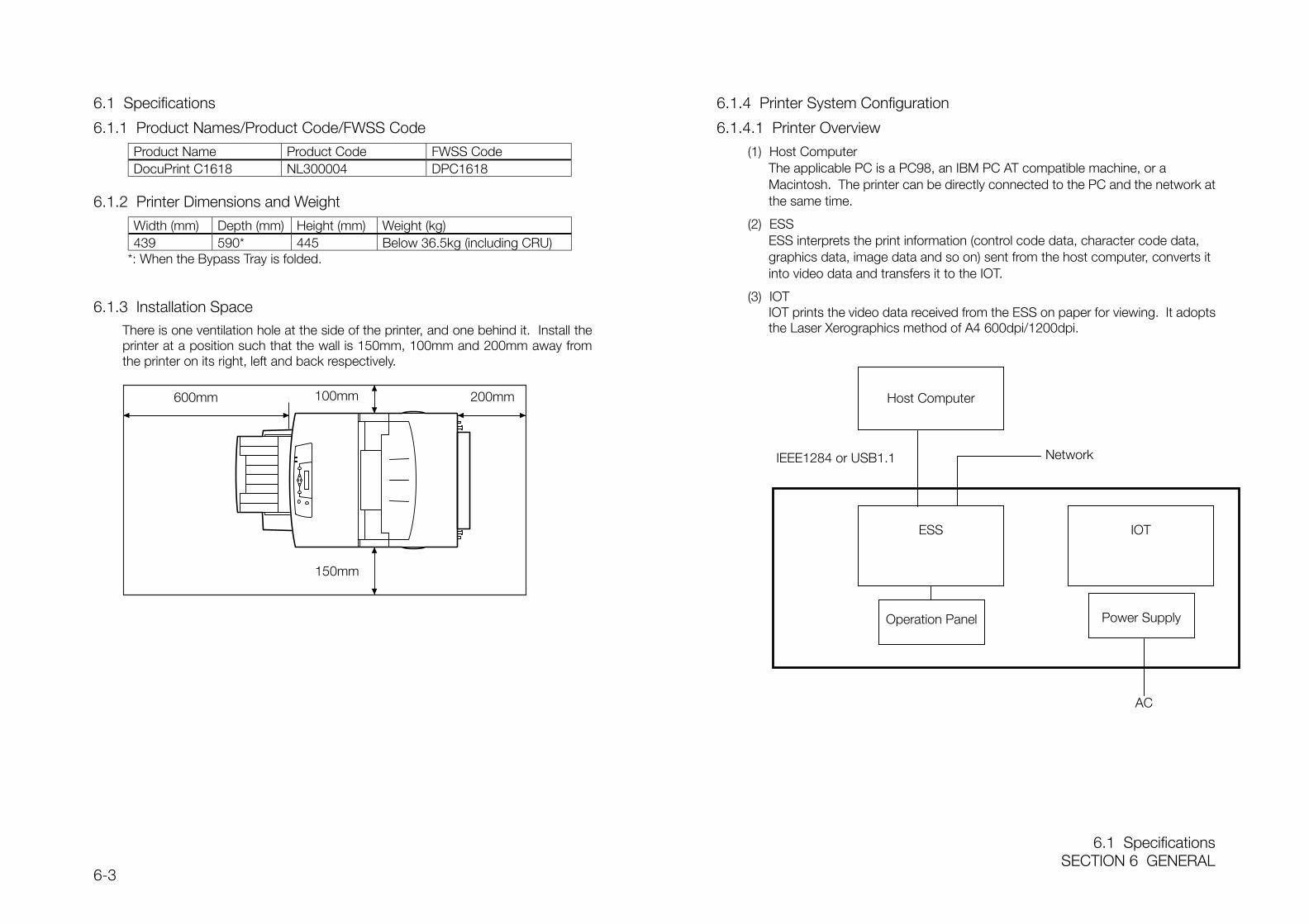
6.1 SpecificationsSECTION 6 GENERAL
6-3
6.1 Specifications
6.1.1 Product Names/Product Code/FWSS Code
Product Name Product Code FWSS CodeDocuPrint C1618 NL300004 DPC1618
6.1.2 Printer Dimensions and Weight
Width (mm) Depth (mm) Height (mm) Weight (kg)439 590* 445 Below 36.5kg (including CRU)
*: When the Bypass Tray is folded.
6.1.3 Installation SpaceThere is one ventilation hole at the side of the printer, and one behind it. Install theprinter at a position such that the wall is 150mm, 100mm and 200mm away fromthe printer on its right, left and back respectively.
6.1.4 Printer System Configuration
6.1.4.1 Printer Overview
(1) Host ComputerThe applicable PC is a PC98, an IBM PC AT compatible machine, or aMacintosh. The printer can be directly connected to the PC and the network atthe same time.
(2) ESSESS interprets the print information (control code data, character code data,graphics data, image data and so on) sent from the host computer, converts itinto video data and transfers it to the IOT.
(3) IOTIOT prints the video data received from the ESS on paper for viewing. It adoptsthe Laser Xerographics method of A4 600dpi/1200dpi.
IEEE1284 or USB1.1
150mm
600mm 100mm 200mm Host Computer
ESS IOT
Network
Operation Panel Power Supply
AC
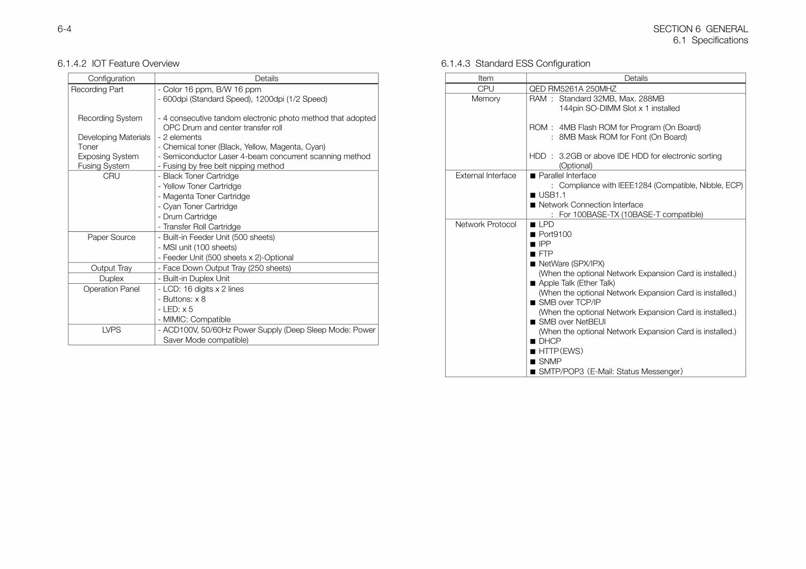
SECTION 6 GENERAL6.1 Specifications
6-4
6.1.4.2 IOT Feature Overview
Configuration DetailsRecording Part
Recording System
Developing MaterialsTonerExposing SystemFusing System
- Color 16 ppm, B/W 16 ppm- 600dpi (Standard Speed), 1200dpi (1/2 Speed)
- 4 consecutive tandom electronic photo method that adopted OPC Drum and center transfer roll
- 2 elements- Chemical toner (Black, Yellow, Magenta, Cyan)- Semiconductor Laser 4-beam concurrent scanning method- Fusing by free belt nipping method
CRU - Black Toner Cartridge- Yellow Toner Cartridge- Magenta Toner Cartridge- Cyan Toner Cartridge- Drum Cartridge- Transfer Roll Cartridge
Paper Source - Built-in Feeder Unit (500 sheets)- MSI unit (100 sheets)- Feeder Unit (500 sheets x 2)-Optional
Output Tray - Face Down Output Tray (250 sheets)Duplex - Built-in Duplex Unit
Operation Panel - LCD: 16 digits x 2 lines- Buttons: x 8- LED: x 5- MIMIC: Compatible
LVPS - ACD100V, 50/60Hz Power Supply (Deep Sleep Mode: PowerSaver Mode compatible)
6.1.4.3 Standard ESS Configuration
Item DetailsCPU QED RM5261A 250MHZ
Memory RAM : Standard 32MB, Max. 288MB144pin SO-DIMM Slot x 1 installed
ROM : 4MB Flash ROM for Program (On Board): 8MB Mask ROM for Font (On Board)
HDD : 3.2GB or above IDE HDD for electronic sorting (Optional)
External Interface Parallel Interface : Compliance with IEEE1284 (Compatible, Nibble, ECP)
USB1.1 Network Connection Interface
: For 100BASE-TX (10BASE-T compatible)Network Protocol LPD
Port9100 IPP FTP NetWare (SPX/IPX)
(When the optional Network Expansion Card is installed.) Apple Talk (Ether Talk)
(When the optional Network Expansion Card is installed.) SMB over TCP/IP
(When the optional Network Expansion Card is installed.) SMB over NetBEUI
(When the optional Network Expansion Card is installed.) DHCP HTTP(EWS) SNMP SMTP/POP3 (E-Mail: Status Messenger)
6.1 SpecificationsSECTION 6 GENERAL
6-5
6.1.5 List of Options
No Product Name Product Code Remarks1 500-sheet Universal Paper Tray EL3000642 Feeder Unit (500 sheets x 2) EL3000633 Expansion RAM Module (128MB) EL300066 144Pin SO-DIMM4 Expansion RAM Module (256MB) EC100141 144Pin SO-DIMM5 Built-in Hard Disk EL300067 For electronic sorting (10GB)6 Network Expansion Card *1 EL3000657 Centronics Cable
(D-Sub25 pin for PC/AT)E3200011 DP190/210 common
8 Centronics Cable(Full pitch 36 pin for PC98)
VD14 Diversion for LaserPress
9 Centronics Cable(Half pitch 36 pin for PC98 MATE)
YH57 Diversion for LaserPress
12 Earthquake Preparedness Kit EL300091*1: This is a card for expanding the network function. By adding this card, it can be
compatible to networks such as NetWare, SMB and AppleTalk, as well as the standard TCP/IP.
6.1.6 Documentation
Packaged with Manual Name Format Manual CodePrinter Setup Guide Paper (A2 2-Sided x 1 sheet) DE-1328
Printer User Guide Paper (Approx. 250P) DE-1329Printer One-point Guide Paper DE-1333Printer PDF file Easy Print Guide Paper DE-1327
CentreWareCD-ROM
Let's Try Color Printing PDF (Approx. 18P) -
CentreWareCD-ROM
Network Guide PDF & DW (Approx. 200P) -
Options 2-Tray Module Guide Paper (Booklet Approx. 8P) DE-1181
6.1.7 System Characteristics
6.1.7.1 Operating Modes
The operating modes are as follows:(1) Running Mode: The printer is operating under conditions such as running or
recording.• Fusing System : Maintains at operating temperature• Exposing System : Rotates at running speed• Recording System : Operating status• Fuser Fan : High Speed rotation status• Rear Fan : High speed rotation• LVPS : Normal mode
(2) Ready Mode: The printer is at ready state.• Fusing System : Maintains at Ready temperature• Exposing System : Stop status• Recording System : Stop status• Fuser Fan : Half Speed rotation status• Rear Fan : Stop status• LVPS : Normal mode
(3) Low Power Mode (Light Sleep Mode):The machine shifts to the Light Sleep Mode when print data is not receivedwithin a specific time in order to reduce power consumption.• Fusing System : Stop status• Exposing System : Stop status• Recording System : Stop status• Fuser Fan : Stop status• Rear Fan : Stop status• LVPS : Normal mode
(4) Power Saver Mode (Deep Sleep Mode):After shifting to the Low Power Mode (Light Sleep Mode) to reduce powerconsumption, the machine shifts to the Power Saver Mode (Deep Sleep Mode)when print data is not received after a longer specific time. The LVPS outputpower to the IOT is completely cut off, and only power to the ESS networkfunction part is supplied.• Fusing System : Stop status• Exposing System : Stop status• Recording System : Stop status• Fuser Fan : Stop status• Rear Fan : Stop status• LVPS : Power Saver mode
SECTION 6 GENERAL6.1 Specifications
6-6
6.1.7.2 Throughput
Indicates the time from the print instruction on the Printer Driver, to the last printpaper being output to the output tray. However, this excludes the Process Controloperation.(OS: Win98, Measurement chart: JEIDA J11, Paper source: Tray 1)
Paper Paper Type Color Throughput
A4 Plain Paper-1 Color Below 60 seconds
A4 Plain Paper-1 B/W Below 60 seconds
6.1.7.3 FPOT
Indicates the time from the print instruction on the Printer Driver, to the print paperbeing output to the output tray. However; this excludes the Process Controloperation.(OS: Win98, Measurement chart: JEIDA J11, Paper source: Tray 1)
Paper Paper Type Color Throughput
A4 Plain Paper-1 Color Below 20 seconds
A4 Plain Paper-1 B/W Below 20 seconds
6.1.7.4 Continuous Print Speed(1) Print speed in same document mode
(OS: Win98, Measurement chart: Not specified, Paper: A4SEF)Paper Type Paper Source Color 2-sided/1-sided
modeAverage PrintSpeed
Plain Paper-1 Not specified Color 1-Sided 16ppm and above
Plain Paper-1 Not specified B/W 1-Sided 16ppm and above
Plain Paper-1 Not specified Color 2-Sided 10ppm and above
Plain Paper-1 Not specified B/W 2-Sided 10ppm and above
Heavyweight-1 Not specified Color 1-Sided 8ppm and above
Heavyweight-1 Not specified B/W 1-Sided 8ppm and above
Transparency Bypass Tray Color 1-Sided 5ppm and above
(2) Print speed in different document modes(Paper source: Not specified, Paper: A4SEF)
OS MeasurementChart
Paper Type Color Average Print Speed
Win98 JEIDA J11 Plain Paper-1 Color 16ppm and above
Win98 JEIDA J11 Plain Paper-1 B/W 16ppm and above
WinNT4.0 JEIDA J11 Plain Paper-1 Color 16ppm and above
WinNT4.0 JEIDA J11 Plain Paper-1 B/W 16ppm and above
MAC8 SDPT-093 Plain Paper-1 Color TBD ppm and above
MAC8 SDPT-093 Plain Paper-1 B/W TBD ppm and above
6.1.7.5 Warmup Time
Event/Status Shifting Time before printing Conditions
Power On Less than 30sec
Returning from Low Power Mode Less than 30sec
Returning from Power Saver Mode Less than 30sec
Temperature 22°C, humidity55%, input voltage 100V
6.1.8 Print Function
6.1.8.1 Image AreaSize Category Image Quality Guaranteed Area500-sheet Universal Tray Area excluding 4mm from the 4 sides (left, right, up, down) of
the paper size.Maximum drawing image quality guaranteed area 207.9mm x347.6mm (8.2" x 13.7")
When running LEF(900mm) from the Bypass
The LEF paper is out of the image quality guaranteecompatibility.
6.1.8.2 Printer Fonts (Japanese: 2 styles, English: 13 styles)
Japanese/European Type Name
Japanese True Type Heisei-Mincho W3
Japanese True Type Heisei-kaku Gothic W5
European True Type CS Times Roman
European True Type CS Times Bold
European True Type CS Times Bold Italic
European True Type CS Times Italic
European True Type CS Courier Medium
European True Type CS Courier Bold
European True Type CS Courier Bold Oblique
European True Type CS Courier Oblique
European True Type CS Triumvirate Regular
European True Type CS Triumvirate Bold
European True Type CS Triumvirate Bold Italic
European True Type CS Triumvirate Italic
European True Type CS Symbol
6.1 SpecificationsSECTION 6 GENERAL
6-7
6.1.8.3 True Type Fonts
Display in Driver NameAlways Use True Type Fonts(Default)
Always download fonts at PC side for printing.
Substitute TrueType fonts withPrinter Fonts
Substitute with the Printer fonts for printingaccording to the TrueType Font table. The TrueTypeFont table can be edited, and which font to bereplaced with the Printer font can be set freely.
6.1.9 Image Processing Features
6.1.9.1 Specify Color/Black & WhiteSelects Color, B/W or Auto. When Auto is selected, the printer checks every pagefor color or black & white data and automatically prints in the respective mode.
6.1.9.2 Paper Type SelectionSelects Plain Paper-1, Plain Paper-2, Transparency, Heavyweight-1, Heavyweight-2,Label, Dedicated Glossy Paper, Postcard, Envelope, Heavyweight (Side 2), DedicatedGlossy Paper (Side 2), Postcard (Side 2), or Envelope (Side 2).However, FX Full Color OHP (V556) cannot be used for Transparency.
6.1.9.3 EconoModeSelects to reduce the amount of toner consumption to 70% (reference value).
6.1.9.4 Color MatchingCompatible with Windows ICM 2/Apple Color Sync 2.
6.1.9.5 Image SettingsAdjusts Brightness, Contrast and Saturation.
6.1.9.6 Color BalanceAdjusts the density of RGB respectively.
6.1.9.7 Auto Image Quality AdjustmentSelects to turn the Auto Image Quality Adjustment feature ON/OFF. Default: OFF.
6.1.9.8 Document Types1) Default Display
Image Quality mode Resolution Purpose and Process OverviewStandard 600dpi General standard image quality
Suitable for printing usual business documents.Performs appropriate processing for each photo,text, or graphic. It has the fastest printing speed.(Default)
High Quality 600dpi General high qualitySuitable for printing business documents at highquality.Performs appropriate processing for each photo,text, or graphic.
High Precision 1200dpi Suitable for printing documents centered with finelines.Improves the reproducibility of fine texts and lines,and reproducibility of fine details in photos.
2) Display in "Display all"Image Quality mode Resolution Purpose and Process OverviewTransparency 600dpi Suitable for printing transparencies.
Suitable for printing and displaying ontransparencies by using the screen for low dpilevel and the color conversion to reduce IOTdefects.
ICM(For Macintosh,Colorsync)
600dpi Suitable for printing after color adjustment with thedisplay with the ICM Adjustment function.
EconoMode 600dpi Prints using the EconoMode.Overall, colors become thinner but theconsumption of toner is reduced.
Presentation 600dpi Suitable for printing presentation materials byreproduction of vivid colors. FX coherency mode.Output colors are the same as those of other FXmachines.
Standard(High Gloss)
600dpi Performs printing with a glossy touch in standardmode.(When using Plain Paper 1/Plain Paper 2)
High Quality(High Gloss)
600dpi Performs printing with a glossy touch in highquality mode.(When using Plain Paper 1/Plain Paper 2)
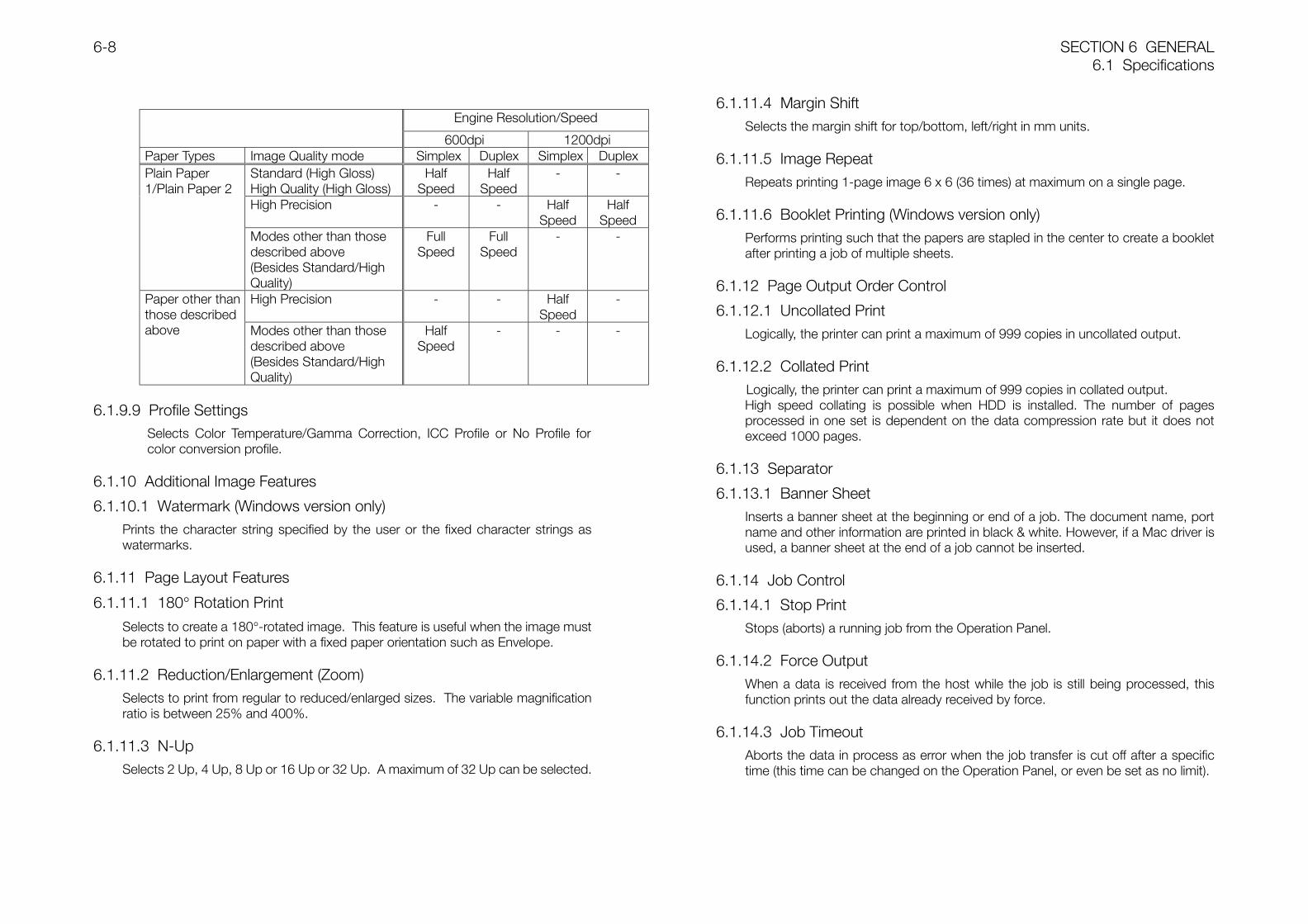
SECTION 6 GENERAL6.1 Specifications
6-8
Engine Resolution/Speed
600dpi 1200dpiPaper Types Image Quality mode Simplex Duplex Simplex Duplex
Standard (High Gloss)High Quality (High Gloss)
HalfSpeed
HalfSpeed
- -
High Precision - - HalfSpeed
HalfSpeed
Plain Paper1/Plain Paper 2
Modes other than thosedescribed above(Besides Standard/HighQuality)
FullSpeed
FullSpeed
- -
High Precision - - HalfSpeed
-Paper other thanthose describedabove Modes other than those
described above(Besides Standard/HighQuality)
HalfSpeed
- - -
6.1.9.9 Profile SettingsSelects Color Temperature/Gamma Correction, ICC Profile or No Profile forcolor conversion profile.
6.1.10 Additional Image Features
6.1.10.1 Watermark (Windows version only)Prints the character string specified by the user or the fixed character strings aswatermarks.
6.1.11 Page Layout Features
6.1.11.1 180° Rotation Print
Selects to create a 180°-rotated image. This feature is useful when the image mustbe rotated to print on paper with a fixed paper orientation such as Envelope.
6.1.11.2 Reduction/Enlargement (Zoom)Selects to print from regular to reduced/enlarged sizes. The variable magnificationratio is between 25% and 400%.
6.1.11.3 N-UpSelects 2 Up, 4 Up, 8 Up or 16 Up or 32 Up. A maximum of 32 Up can be selected.
6.1.11.4 Margin ShiftSelects the margin shift for top/bottom, left/right in mm units.
6.1.11.5 Image RepeatRepeats printing 1-page image 6 x 6 (36 times) at maximum on a single page.
6.1.11.6 Booklet Printing (Windows version only)Performs printing such that the papers are stapled in the center to create a bookletafter printing a job of multiple sheets.
6.1.12 Page Output Order Control
6.1.12.1 Uncollated PrintLogically, the printer can print a maximum of 999 copies in uncollated output.
6.1.12.2 Collated PrintLogically, the printer can print a maximum of 999 copies in collated output.High speed collating is possible when HDD is installed. The number of pagesprocessed in one set is dependent on the data compression rate but it does notexceed 1000 pages.
6.1.13 Separator
6.1.13.1 Banner SheetInserts a banner sheet at the beginning or end of a job. The document name, portname and other information are printed in black & white. However, if a Mac driver isused, a banner sheet at the end of a job cannot be inserted.
6.1.14 Job Control
6.1.14.1 Stop PrintStops (aborts) a running job from the Operation Panel.
6.1.14.2 Force OutputWhen a data is received from the host while the job is still being processed, thisfunction prints out the data already received by force.
6.1.14.3 Job TimeoutAborts the data in process as error when the job transfer is cut off after a specifictime (this time can be changed on the Operation Panel, or even be set as no limit).
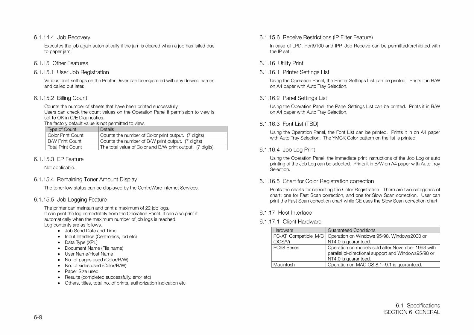
6.1 SpecificationsSECTION 6 GENERAL
6-9
6.1.14.4 Job RecoveryExecutes the job again automatically if the jam is cleared when a job has failed dueto paper jam.
6.1.15 Other Features
6.1.15.1 User Job RegistrationVarious print settings on the Printer Driver can be registered with any desired namesand called out later.
6.1.15.2 Billing CountCounts the number of sheets that have been printed successfully.Users can check the count values on the Operation Panel if permission to view isset to OK in C/E Diagnostics.The factory default value is not permitted to view.
Type of Count DetailsColor Print Count Counts the number of Color print output. (7 digits)B/W Print Count Counts the number of B/W print output. (7 digits)Total Print Count The total value of Color and B/W print output. (7 digits)
6.1.15.3 EP FeatureNot applicable.
6.1.15.4 Remaining Toner Amount DisplayThe toner low status can be displayed by the CentreWare Internet Services.
6.1.15.5 Job Logging FeatureThe printer can maintain and print a maximum of 22 job logs.It can print the log immediately from the Operation Panel. It can also print itautomatically when the maximum number of job logs is reached.Log contents are as follows.
• Job Send Date and Time• Input Interface (Centronics, lpd etc)• Data Type (XPL)• Document Name (File name)• User Name/Host Name• No. of pages used (Color/B/W)• No. of sides used (Color/B/W)• Paper Size used• Results (completed successfully, error etc)• Others, titles, total no. of prints, authorization indication etc
6.1.15.6 Receive Restrictions (IP Filter Feature)In case of LPD, Port9100 and IPP, Job Receive can be permitted/prohibited withthe IP set.
6.1.16 Utility Print
6.1.16.1 Printer Settings ListUsing the Operation Panel, the Printer Settings List can be printed. Prints it in B/Won A4 paper with Auto Tray Selection.
6.1.16.2 Panel Settings ListUsing the Operation Panel, the Panel Settings List can be printed. Prints it in B/Won A4 paper with Auto Tray Selection.
6.1.16.3 Font List (TBD)Using the Operation Panel, the Font List can be printed. Prints it in on A4 paperwith Auto Tray Selection. The YMCK Color pattern on the list is printed.
6.1.16.4 Job Log PrintUsing the Operation Panel, the immediate print instructions of the Job Log or autoprinting of the Job Log can be selected. Prints it in B/W on A4 paper with Auto TraySelection.
6.1.16.5 Chart for Color Registration correctionPrints the charts for correcting the Color Registration. There are two categories ofchart: one for Fast Scan correction, and one for Slow Scan correction. User canprint the Fast Scan correction chart while CE uses the Slow Scan correction chart.
6.1.17 Host Interface
6.1.17.1 Client Hardware
Hardware Guaranteed ConditionsPC-AT Compatible M/C(DOS/V)
Operation on Windows 95/98, Windows2000 orNT4.0 is guaranteed.
PC98 Series Operation on models sold after November 1993 withparallel bi-directional support and Windows95/98 orNT4.0 is guaranteed.
Macintosh Operation on MAC OS 8.1~9.1 is guaranteed.
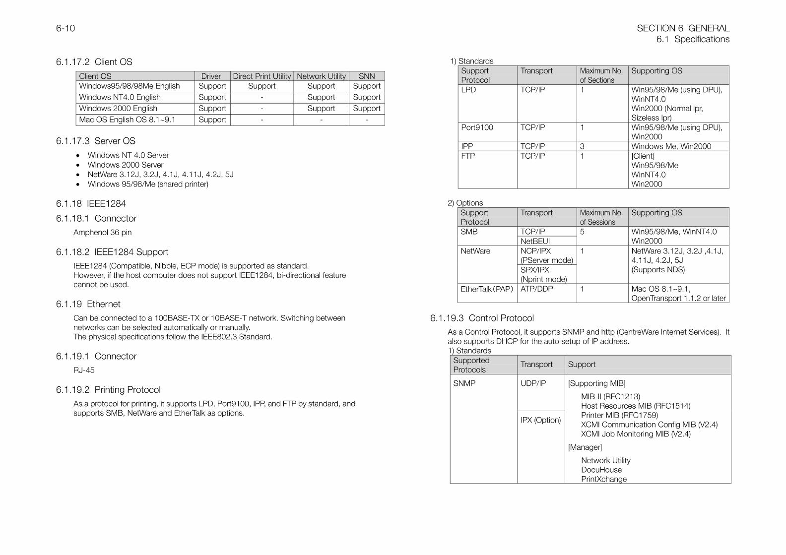
SECTION 6 GENERAL6.1 Specifications
6-10
6.1.17.2 Client OS
Client OS Driver Direct Print Utility Network Utility SNNWindows95/98/98Me English Support Support Support SupportWindows NT4.0 English Support - Support SupportWindows 2000 English Support - Support SupportMac OS English OS 8.1~9.1 Support - - -
6.1.17.3 Server OS
• Windows NT 4.0 Server• Windows 2000 Server• NetWare 3.12J, 3.2J, 4.1J, 4.11J, 4.2J, 5J• Windows 95/98/Me (shared printer)
6.1.18 IEEE1284
6.1.18.1 ConnectorAmphenol 36 pin
6.1.18.2 IEEE1284 SupportIEEE1284 (Compatible, Nibble, ECP mode) is supported as standard.However, if the host computer does not support IEEE1284, bi-directional featurecannot be used.
6.1.19 EthernetCan be connected to a 100BASE-TX or 10BASE-T network. Switching betweennetworks can be selected automatically or manually.The physical specifications follow the IEEE802.3 Standard.
6.1.19.1 ConnectorRJ-45
6.1.19.2 Printing ProtocolAs a protocol for printing, it supports LPD, Port9100, IPP, and FTP by standard, andsupports SMB, NetWare and EtherTalk as options.
1) StandardsSupportProtocol
Transport Maximum No.of Sections
Supporting OS
LPD TCP/IP 1 Win95/98/Me (using DPU),WinNT4.0Win2000 (Normal lpr,Sizeless lpr)
Port9100 TCP/IP 1 Win95/98/Me (using DPU),Win2000
IPP TCP/IP 3 Windows Me, Win2000FTP TCP/IP 1 [Client]
Win95/98/MeWinNT4.0Win2000
2) OptionsSupportProtocol
Transport Maximum No.of Sessions
Supporting OS
TCP/IPSMBNetBEUI
5 Win95/98/Me, WinNT4.0Win2000
NCP/IPX(PServer mode)
NetWare
SPX/IPX(Nprint mode)
1 NetWare 3.12J, 3.2J ,4.1J,4.11J, 4.2J, 5J(Supports NDS)
EtherTalk(PAP) ATP/DDP 1 Mac OS 8.1~9.1,OpenTransport 1.1.2 or later
6.1.19.3 Control ProtocolAs a Control Protocol, it supports SNMP and http (CentreWare Internet Services). Italso supports DHCP for the auto setup of IP address.1) Standards
SupportedProtocols
Transport Support
UDP/IPSNMP
IPX (Option)
[Supporting MIB]
MIB-II (RFC1213)Host Resources MIB (RFC1514)Printer MIB (RFC1759)XCMI Communication Config MIB (V2.4)XCMI Job Monitoring MIB (V2.4)
[Manager]
Network UtilityDocuHousePrintXchange
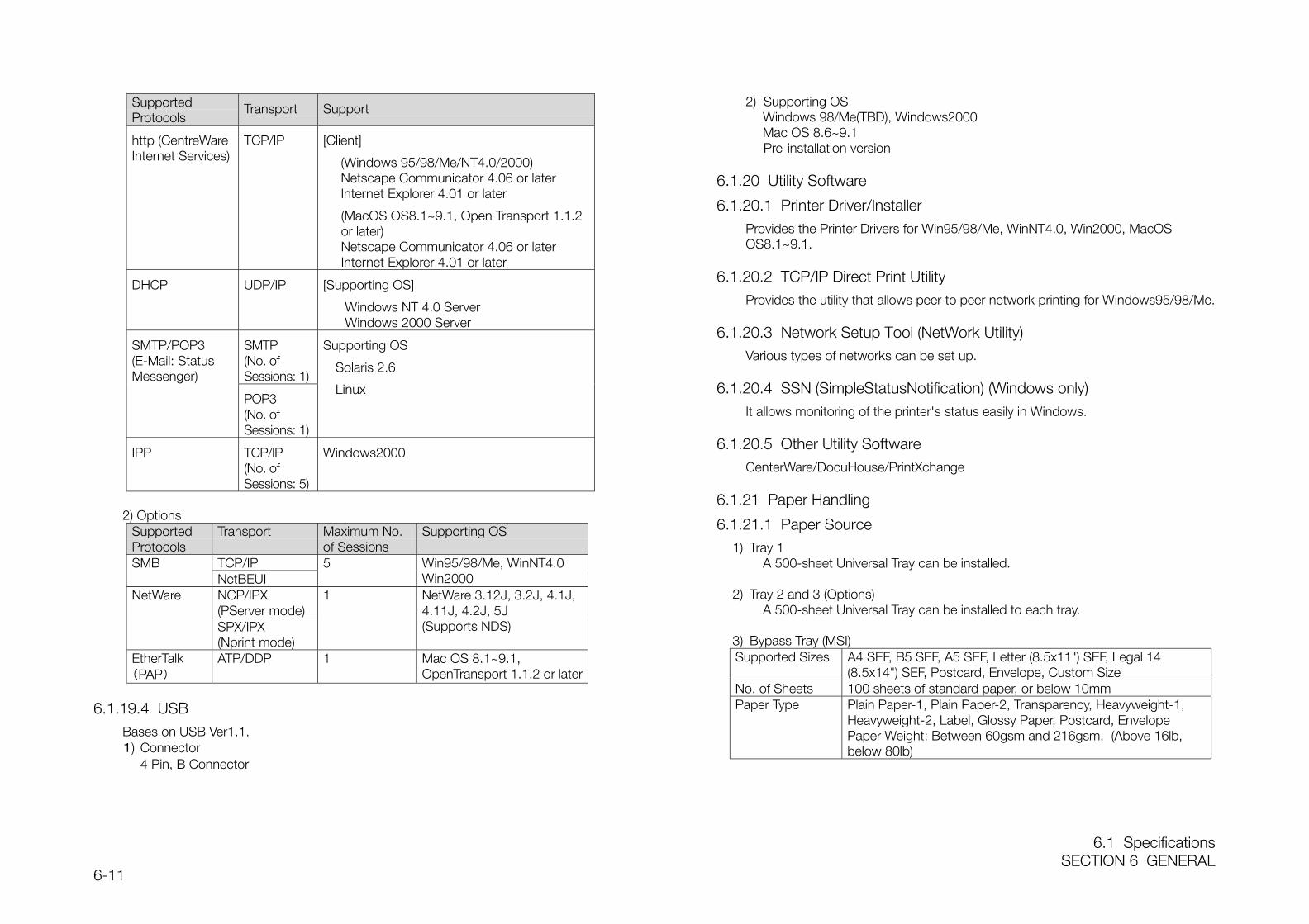
6.1 SpecificationsSECTION 6 GENERAL
6-11
SupportedProtocols
Transport Support
http (CentreWareInternet Services)
TCP/IP [Client]
(Windows 95/98/Me/NT4.0/2000)Netscape Communicator 4.06 or laterInternet Explorer 4.01 or later
(MacOS OS8.1~9.1, Open Transport 1.1.2or later)Netscape Communicator 4.06 or laterInternet Explorer 4.01 or later
DHCP UDP/IP [Supporting OS]
Windows NT 4.0 ServerWindows 2000 Server
SMTP(No. ofSessions: 1)
SMTP/POP3(E-Mail: StatusMessenger)
POP3(No. ofSessions: 1)
Supporting OS
Solaris 2.6
Linux
IPP TCP/IP(No. ofSessions: 5)
Windows2000
2) OptionsSupportedProtocols
Transport Maximum No.of Sessions
Supporting OS
TCP/IPSMBNetBEUI
5 Win95/98/Me, WinNT4.0Win2000
NCP/IPX(PServer mode)
NetWare
SPX/IPX(Nprint mode)
1 NetWare 3.12J, 3.2J, 4.1J,4.11J, 4.2J, 5J(Supports NDS)
EtherTalk(PAP)
ATP/DDP 1 Mac OS 8.1~9.1,OpenTransport 1.1.2 or later
6.1.19.4 USBBases on USB Ver1.1.1) Connector
4 Pin, B Connector
2) Supporting OSWindows 98/Me(TBD), Windows2000Mac OS 8.6~9.1Pre-installation version
6.1.20 Utility Software
6.1.20.1 Printer Driver/InstallerProvides the Printer Drivers for Win95/98/Me, WinNT4.0, Win2000, MacOSOS8.1~9.1.
6.1.20.2 TCP/IP Direct Print UtilityProvides the utility that allows peer to peer network printing for Windows95/98/Me.
6.1.20.3 Network Setup Tool (NetWork Utility)Various types of networks can be set up.
6.1.20.4 SSN (SimpleStatusNotification) (Windows only)It allows monitoring of the printer's status easily in Windows.
6.1.20.5 Other Utility SoftwareCenterWare/DocuHouse/PrintXchange
6.1.21 Paper Handling
6.1.21.1 Paper Source1) Tray 1
A 500-sheet Universal Tray can be installed.
2) Tray 2 and 3 (Options)A 500-sheet Universal Tray can be installed to each tray.
3) Bypass Tray (MSI)Supported Sizes A4 SEF, B5 SEF, A5 SEF, Letter (8.5x11") SEF, Legal 14
(8.5x14") SEF, Postcard, Envelope, Custom SizeNo. of Sheets 100 sheets of standard paper, or below 10mmPaper Type Plain Paper-1, Plain Paper-2, Transparency, Heavyweight-1,
Heavyweight-2, Label, Glossy Paper, Postcard, EnvelopePaper Weight: Between 60gsm and 216gsm. (Above 16lb,below 80lb)
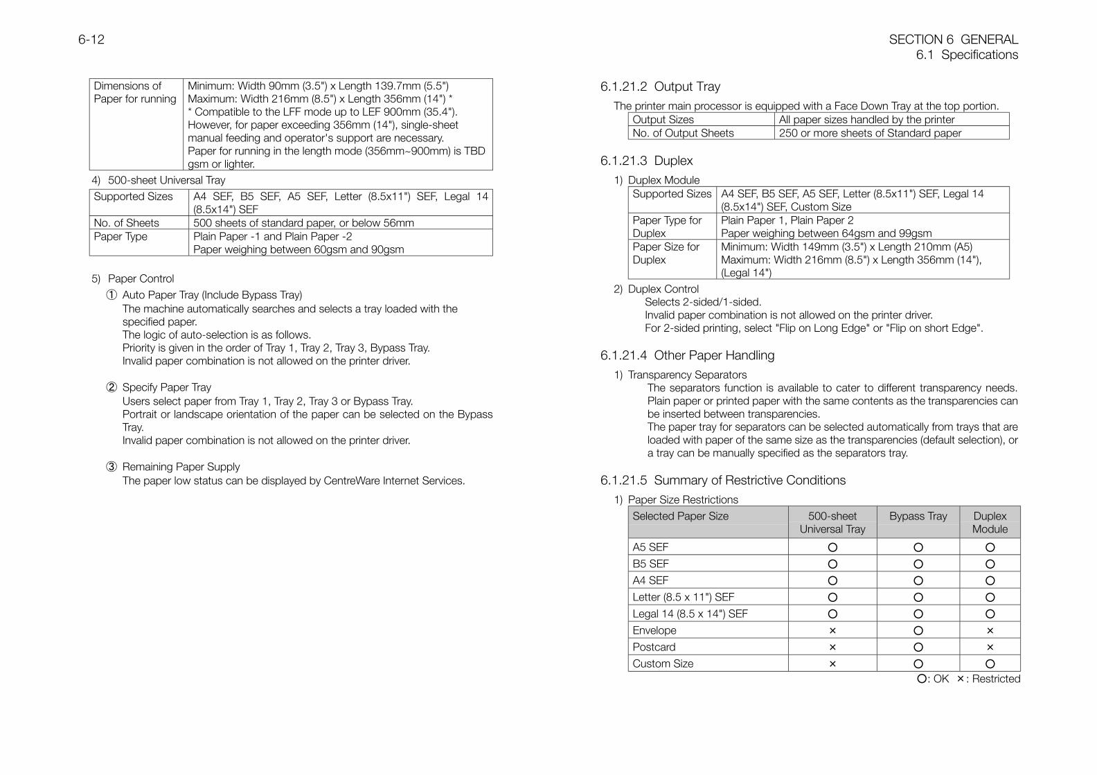
SECTION 6 GENERAL6.1 Specifications
6-12
Dimensions ofPaper for running
Minimum: Width 90mm (3.5") x Length 139.7mm (5.5")Maximum: Width 216mm (8.5") x Length 356mm (14") ** Compatible to the LFF mode up to LEF 900mm (35.4").However, for paper exceeding 356mm (14"), single-sheetmanual feeding and operator's support are necessary.Paper for running in the length mode (356mm~900mm) is TBDgsm or lighter.
4) 500-sheet Universal TraySupported Sizes A4 SEF, B5 SEF, A5 SEF, Letter (8.5x11") SEF, Legal 14
(8.5x14") SEFNo. of Sheets 500 sheets of standard paper, or below 56mmPaper Type Plain Paper -1 and Plain Paper -2
Paper weighing between 60gsm and 90gsm
5) Paper Control① Auto Paper Tray (Include Bypass Tray)
The machine automatically searches and selects a tray loaded with thespecified paper.The logic of auto-selection is as follows.Priority is given in the order of Tray 1, Tray 2, Tray 3, Bypass Tray.Invalid paper combination is not allowed on the printer driver.
② Specify Paper TrayUsers select paper from Tray 1, Tray 2, Tray 3 or Bypass Tray.Portrait or landscape orientation of the paper can be selected on the BypassTray.Invalid paper combination is not allowed on the printer driver.
③ Remaining Paper SupplyThe paper low status can be displayed by CentreWare Internet Services.
6.1.21.2 Output TrayThe printer main processor is equipped with a Face Down Tray at the top portion.
Output Sizes All paper sizes handled by the printerNo. of Output Sheets 250 or more sheets of Standard paper
6.1.21.3 Duplex1) Duplex Module
Supported Sizes A4 SEF, B5 SEF, A5 SEF, Letter (8.5x11") SEF, Legal 14(8.5x14") SEF, Custom Size
Paper Type forDuplex
Plain Paper 1, Plain Paper 2Paper weighing between 64gsm and 99gsm
Paper Size forDuplex
Minimum: Width 149mm (3.5") x Length 210mm (A5)Maximum: Width 216mm (8.5") x Length 356mm (14"),(Legal 14")
2) Duplex ControlSelects 2-sided/1-sided.Invalid paper combination is not allowed on the printer driver.For 2-sided printing, select "Flip on Long Edge" or "Flip on short Edge".
6.1.21.4 Other Paper Handling1) Transparency Separators
The separators function is available to cater to different transparency needs.Plain paper or printed paper with the same contents as the transparencies canbe inserted between transparencies.The paper tray for separators can be selected automatically from trays that areloaded with paper of the same size as the transparencies (default selection), ora tray can be manually specified as the separators tray.
6.1.21.5 Summary of Restrictive Conditions1) Paper Size Restrictions
Selected Paper Size 500-sheetUniversal Tray
Bypass Tray DuplexModule
A5 SEF
B5 SEF
A4 SEF
Letter (8.5 x 11") SEF
Legal 14 (8.5 x 14") SEF
Envelope × ×
Postcard × ×
Custom Size ×
: OK ×: Restricted
6.1 SpecificationsSECTION 6 GENERAL
6-13
2) Paper Type RestrictionsSelected Paper Size 500-sheet
Universal TrayBypass Tray Duplex
Module
Plain Paper1
Plain Paper2
Transparency × ×
Heavyweight-1 × ×
Heavyweight-2 × ×
Label × ×
Dedicated Glossy Paper × ×
Postcard × ×
Envelope × ×
Side 2 (Heavyweight, DedicatedGlossy Paper, Postcard,Envelope)
× ×
: OK ×: Restricted
6.1.22 Power Supply Operating Voltage/Frequency
Phase Single phase 2-line typeInput Voltage 100V ± 10%Frequency 50Hz/60Hz ± 3Hz
6.1.23 Rated Consumption Power
Mode Consumption PowerRun Mode 850W or below (Maximum: At Fuser ON)
450W or below (Average) *1Ready Mode 850W or below (Maximum: At Fuser ON)
180W or below (Average) *2Low Power Mode (Light Sleep Mode) 45W or below
Compliance to International Energy StarPower Saver Mode (Deep Sleep Mode) Less than 5W
*1: Average of continuous printing*2: Average when Fuser is at Ready temperature
6.1.24 NoiseReady Mode: 35dB(A) or lessWhen printing:
Printer Optional FeederWhen cassette
is runningWhen MSI is
runningWhen cassette is
runningStandard (600dpi) 52.0 dB(A) 54.0 dB(A) 54.0 dB(A)High Precision/HighGloss (At Half Speed)
53.0 dB(A) 55.0 dB(A) 55.0 dB(A)
6.1.25 Firmware Update FeatureUser can overwrite (update) the ESS Firmware and Net Expansion Card fromexternal.
Replacement targets Via IEEE1284 Via Net (ftp) Via Net (web)
ESS Yes Yes No
Network Expansion Card Yes Yes No
MCU No No No
SECTION 6 GENERAL6.3 Consumables
6-14
6.2 Tools/Service Consumables
6.2.1 Tools• 499T 9588 (Tool manufactured by AMP)
6.2.2 Service ConsumablesThere are no machine-specific service consumables.
6.3 Consumables
Consumables Product Code No. of Print Pages *1Black Toner Cartridge CT2000128 8,500 pages printCyan Toner Cartridge CT2000129 6,000 pages printMagenta Toner Cartridge CT2000130 6,000 pages printYellow Toner Cartridge CT2000131 6,000 pages printDrum Cartridge CT3500084 30,000 pages printTransfer Roll Cartridge(Including Waste Toner Bottle)
CWAA0416 25,000 pages print
※1: Usage conditionsPaper Size : A4 LEF Print Ratio : 5%B/W/Color Ratio : 1:1 No. of Print Sheets once : Average 4 sheets
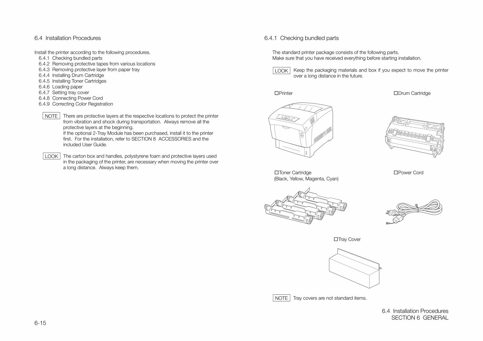
6.4 Installation ProceduresSECTION 6 GENERAL
6-15
6.4 Installation Procedures
Install the printer according to the following procedures.6.4.1 Checking bundled parts6.4.2 Removing protective tapes from various locations6.4.3 Removing protective layer from paper tray6.4.4 Installing Drum Cartridge6.4.5 Installing Toner Cartridges6.4.6 Loading paper6.4.7 Setting tray cover6.4.8 Connecting Power Cord6.4.9 Correcting Color Registration
There are protective layers at the respective locations to protect the printerfrom vibration and shock during transportation. Always remove all theprotective layers at the beginning.If the optional 2-Tray Module has been purchased, install it to the printerfirst. For the installation, refer to SECTION 8 ACCESSORIES and theincluded User Guide.
The carton box and handles, polystyrene foam and protective layers usedin the packaging of the printer, are necessary when moving the printer overa long distance. Always keep them.
6.4.1 Checking bundled parts
The standard printer package consists of the following parts.Make sure that you have received everything before starting installation.
Keep the packaging materials and box if you expect to move the printerover a long distance in the future.
Printer Drum Cartridge
Toner Cartridge Power Cord (Black, Yellow, Magenta, Cyan)
Tray Cover
Tray covers are not standard items.
NOTE
LOOK
LOOK
NOTE
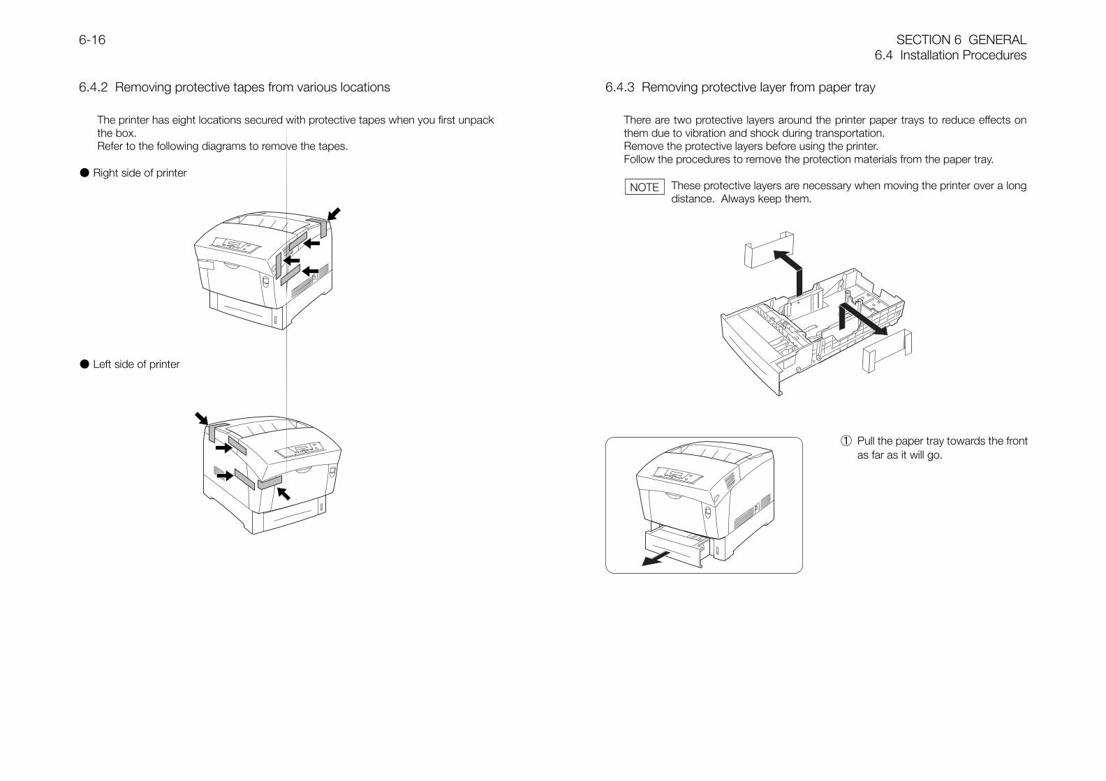
SECTION 6 GENERAL6.4 Installation Procedures
6-16
6.4.2 Removing protective tapes from various locations
The printer has eight locations secured with protective tapes when you first unpackthe box.Refer to the following diagrams to remove the tapes.
Right side of printer
Left side of printer
6.4.3 Removing protective layer from paper tray
There are two protective layers around the printer paper trays to reduce effects onthem due to vibration and shock during transportation.Remove the protective layers before using the printer.Follow the procedures to remove the protection materials from the paper tray.
These protective layers are necessary when moving the printer over a longdistance. Always keep them.
① Pull the paper tray towards the frontas far as it will go.
NOTE
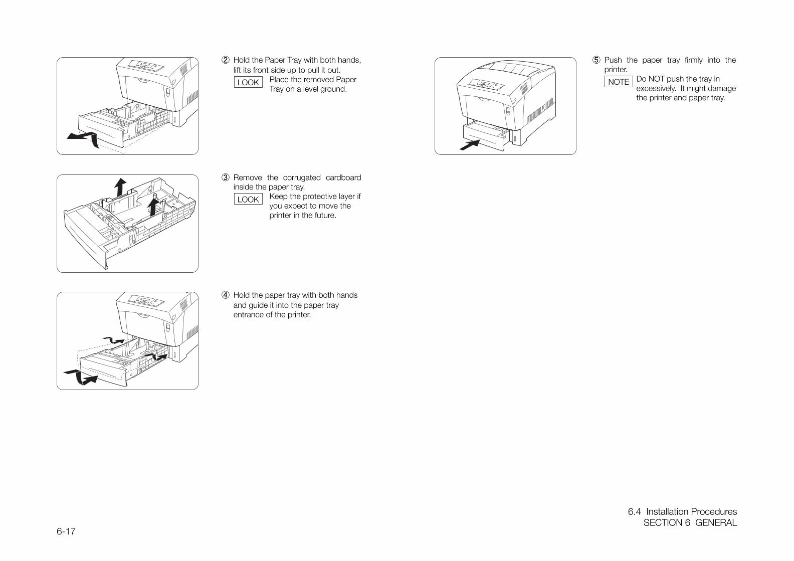
6.4 Installation ProceduresSECTION 6 GENERAL
6-17
③ Remove the corrugated cardboardinside the paper tray.
Keep the protective layer ifyou expect to move theprinter in the future.
② Hold the Paper Tray with both hands,lift its front side up to pull it out.
Place the removed Paper Tray on a level ground.
⑤ Push the paper tray firmly into theprinter.
Do NOT push the tray inexcessively. It might damagethe printer and paper tray.
④ Hold the paper tray with both handsand guide it into the paper trayentrance of the printer.
LOOK
LOOK
NOTE
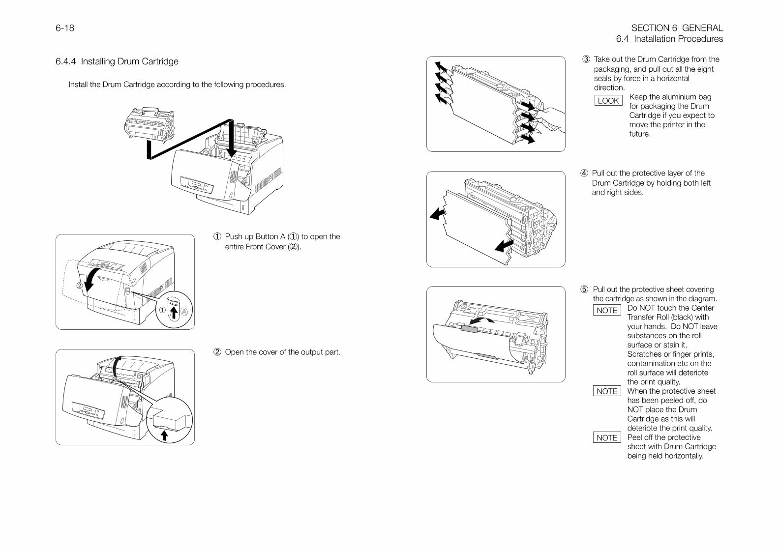
SECTION 6 GENERAL6.4 Installation Procedures
6-18
6.4.4 Installing Drum Cartridge
Install the Drum Cartridge according to the following procedures.
① Push up Button A (①) to open theentire Front Cover (②).
② Open the cover of the output part.
④ Pull out the protective layer of theDrum Cartridge by holding both leftand right sides.
③ Take out the Drum Cartridge from thepackaging, and pull out all the eightseals by force in a horizontaldirection.
Keep the aluminium bagfor packaging the DrumCartridge if you expect tomove the printer in thefuture.
⑤ Pull out the protective sheet coveringthe cartridge as shown in the diagram.
Do NOT touch the CenterTransfer Roll (black) withyour hands. Do NOT leavesubstances on the rollsurface or stain it.Scratches or finger prints,contamination etc on theroll surface will deteriotethe print quality.When the protective sheethas been peeled off, doNOT place the DrumCartridge as this willdeteriote the print quality.Peel off the protectivesheet with Drum Cartridgebeing held horizontally.
LOOK
NOTE
NOTE
NOTE
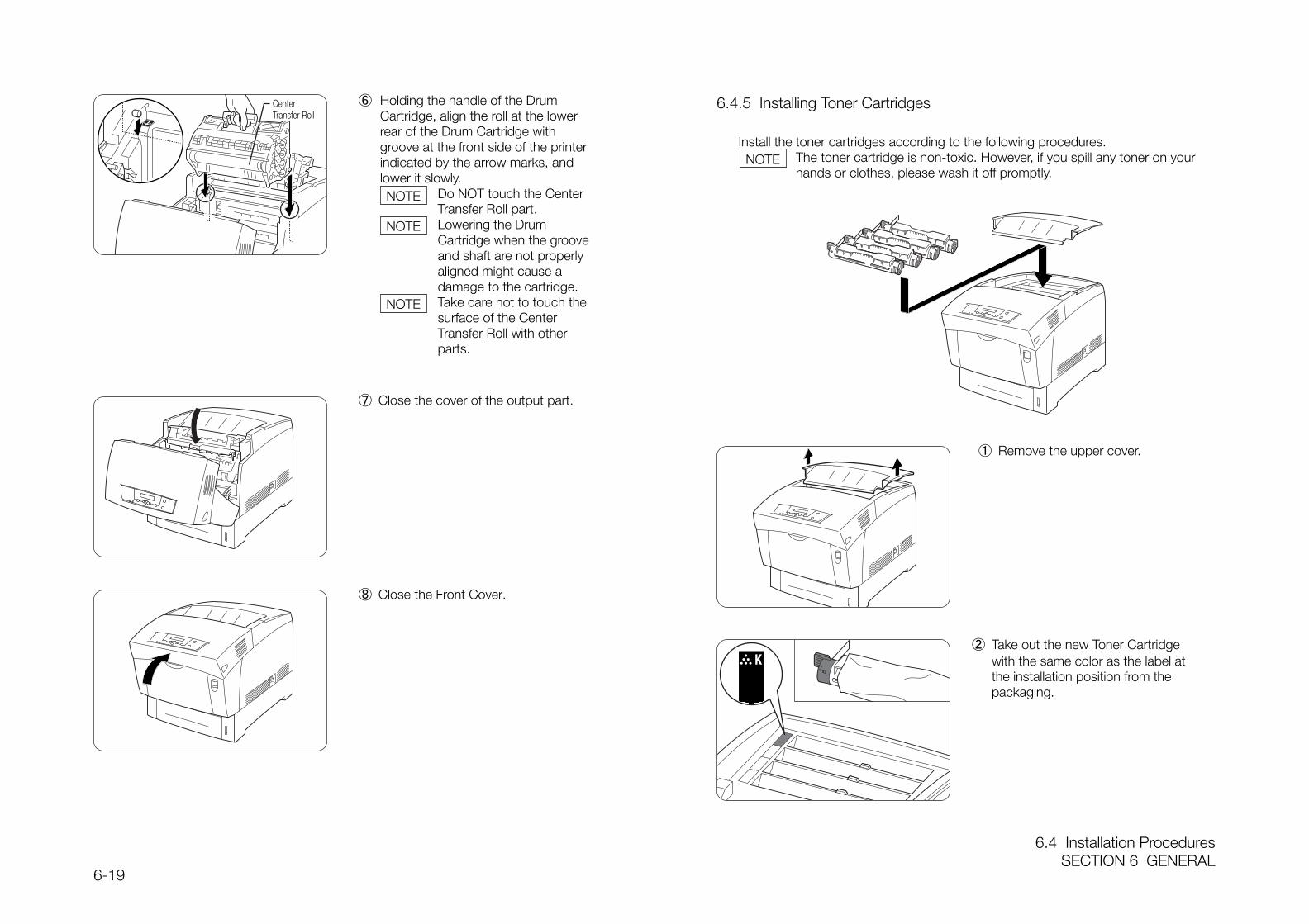
6.4 Installation ProceduresSECTION 6 GENERAL
6-19
6.4.5 Installing Toner Cartridges
Install the toner cartridges according to the following procedures.The toner cartridge is non-toxic. However, if you spill any toner on yourhands or clothes, please wash it off promptly.
⑦ Close the cover of the output part.
⑧ Close the Front Cover.
① Remove the upper cover.
② Take out the new Toner Cartridgewith the same color as the label atthe installation position from thepackaging.
⑥ Holding the handle of the DrumCartridge, align the roll at the lowerrear of the Drum Cartridge withgroove at the front side of the printerindicated by the arrow marks, andlower it slowly.
Do NOT touch the CenterTransfer Roll part.Lowering the DrumCartridge when the grooveand shaft are not properlyaligned might cause adamage to the cartridge.Take care not to touch thesurface of the CenterTransfer Roll with otherparts.
CenterTransfer Roll
NOTE
NOTE
NOTE
NOTE
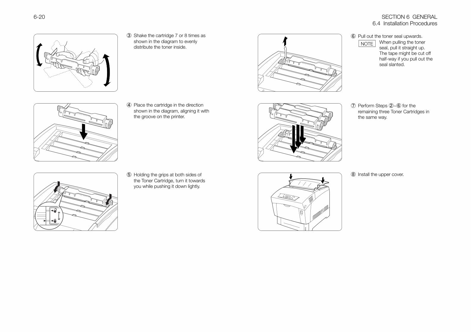
SECTION 6 GENERAL6.4 Installation Procedures
6-20
③ Shake the cartridge 7 or 8 times asshown in the diagram to evenlydistribute the toner inside.
④ Place the cartridge in the directionshown in the diagram, aligning it withthe groove on the printer.
⑤ Holding the grips at both sides ofthe Toner Cartridge, turn it towardsyou while pushing it down lightly.
⑥ Pull out the toner seal upwards.When pulling the tonerseal, pull it straight up.The tape might be cut offhalf-way if you pull out theseal slanted.
⑦ Perform Steps ②~⑥ for theremaining three Toner Cartridges inthe same way.
⑧ Install the upper cover.
NOTE
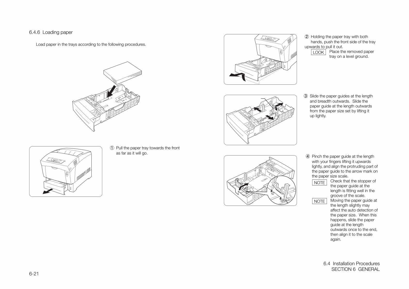
6.4 Installation ProceduresSECTION 6 GENERAL
6-21
6.4.6 Loading paper
Load paper in the trays according to the following procedures.
① Pull the paper tray towards the frontas far as it will go.
③ Slide the paper guides at the length and breadth outwards. Slide the paper guide at the length outwards from the paper size set by lifting it up lightly.
② Holding the paper tray with both hands, push the front side of the tray
upwards to pull it out.Place the removed papertray on a level ground.
④ Pinch the paper guide at the lengthwith your fingers lifting it upwardslightly, and align the protruding part ofthe paper guide to the arrow mark onthe paper size scale.
Check that the stopper ofthe paper guide at thelength is fitting well in thegroove of the scale.Moving the paper guide atthe length slightly mayaffect the auto detection ofthe paper size. When thishappens, slide the paperguide at the lengthoutwards once to the end,then align it to the scaleagain.
LOOK
NOTE
NOTE
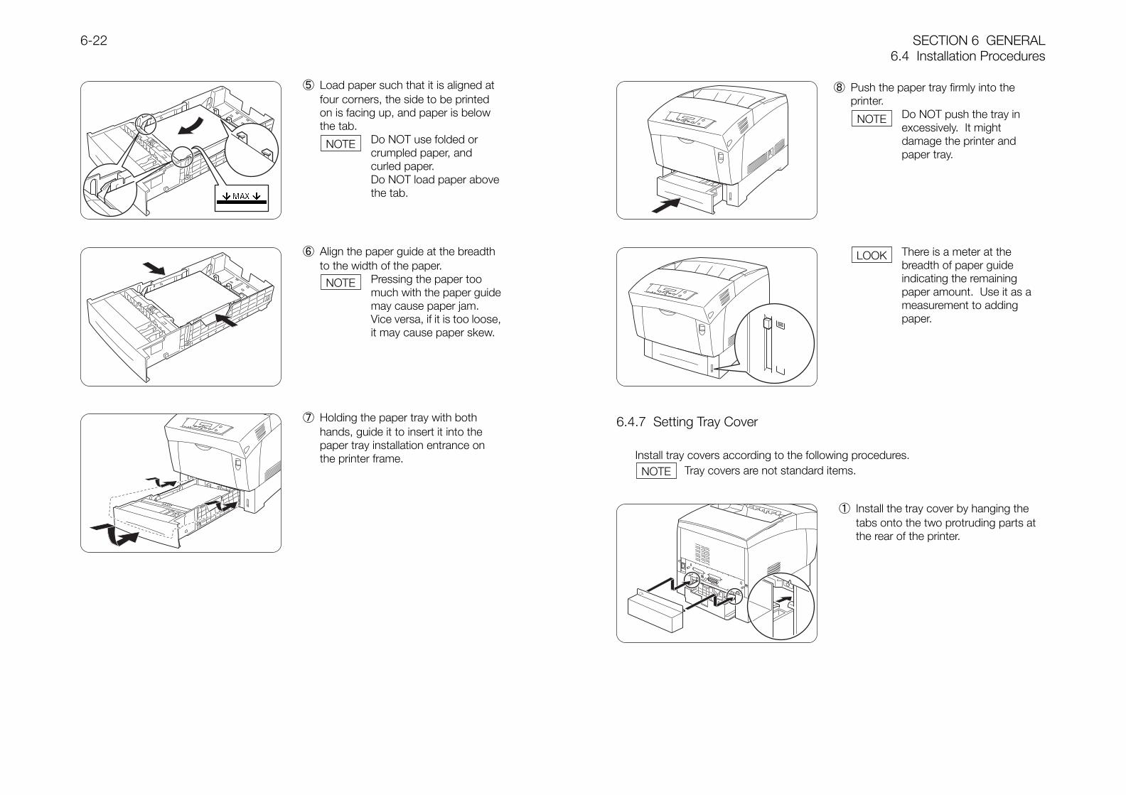
SECTION 6 GENERAL6.4 Installation Procedures
6-22
6.4.7 Setting Tray Cover
Install tray covers according to the following procedures.Tray covers are not standard items.
⑤ Load paper such that it is aligned atfour corners, the side to be printedon is facing up, and paper is belowthe tab.
Do NOT use folded orcrumpled paper, andcurled paper.Do NOT load paper abovethe tab.
⑥ Align the paper guide at the breadthto the width of the paper.
Pressing the paper toomuch with the paper guidemay cause paper jam.Vice versa, if it is too loose,it may cause paper skew.
⑦ Holding the paper tray with bothhands, guide it to insert it into thepaper tray installation entrance onthe printer frame.
① Install the tray cover by hanging thetabs onto the two protruding parts atthe rear of the printer.
⑧ Push the paper tray firmly into theprinter.
Do NOT push the tray inexcessively. It mightdamage the printer andpaper tray.
There is a meter at thebreadth of paper guideindicating the remainingpaper amount. Use it as ameasurement to addingpaper.
NOTE
NOTE
NOTE
LOOK
NOTE
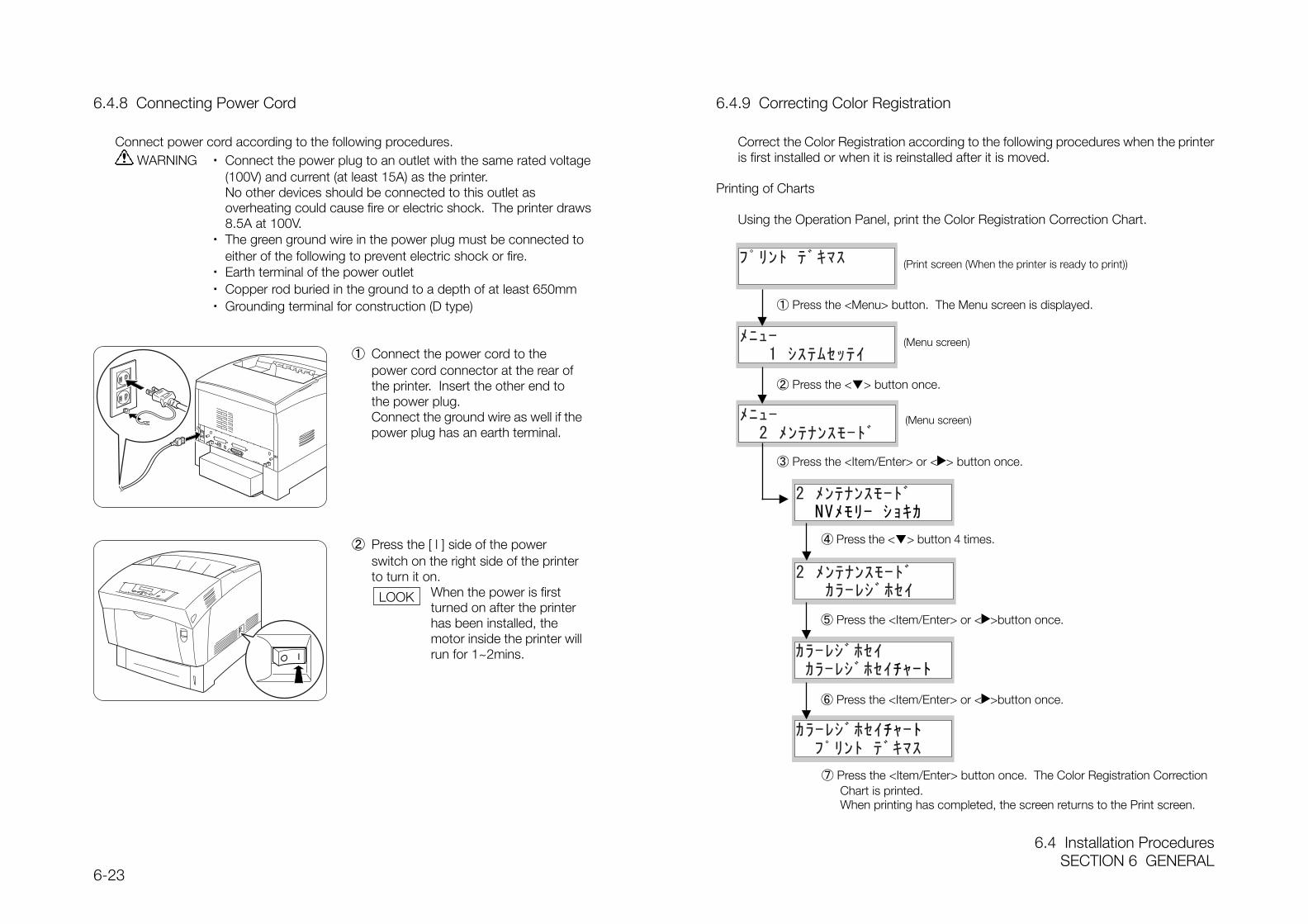
6.4 Installation ProceduresSECTION 6 GENERAL
6-23
6.4.8 Connecting Power Cord
Connect power cord according to the following procedures. WARNING ・ Connect the power plug to an outlet with the same rated voltage
(100V) and current (at least 15A) as the printer.No other devices should be connected to this outlet asoverheating could cause fire or electric shock. The printer draws8.5A at 100V.
・ The green ground wire in the power plug must be connected toeither of the following to prevent electric shock or fire.
・ Earth terminal of the power outlet・ Copper rod buried in the ground to a depth of at least 650mm・ Grounding terminal for construction (D type)
6.4.9 Correcting Color Registration
Correct the Color Registration according to the following procedures when the printeris first installed or when it is reinstalled after it is moved.
Printing of Charts
Using the Operation Panel, print the Color Registration Correction Chart.
① Connect the power cord to thepower cord connector at the rear ofthe printer. Insert the other end tothe power plug.Connect the ground wire as well if thepower plug has an earth terminal.
② Press the [ l ] side of the powerswitch on the right side of the printerto turn it on.
When the power is firstturned on after the printerhas been installed, themotor inside the printer willrun for 1~2mins.
(Print screen (When the printer is ready to print))
① Press the <Menu> button. The Menu screen is displayed.
(Menu screen)
② Press the <> button once.
(Menu screen)
③ Press the <Item/Enter> or < > button once.
④ Press the <> button 4 times.
⑤ Press the <Item/Enter> or < >button once.
⑥ Press the <Item/Enter> or < >button once.
⑦ Press the <Item/Enter> button once. The Color Registration CorrectionChart is printed.When printing has completed, the screen returns to the Print screen.
LOOK
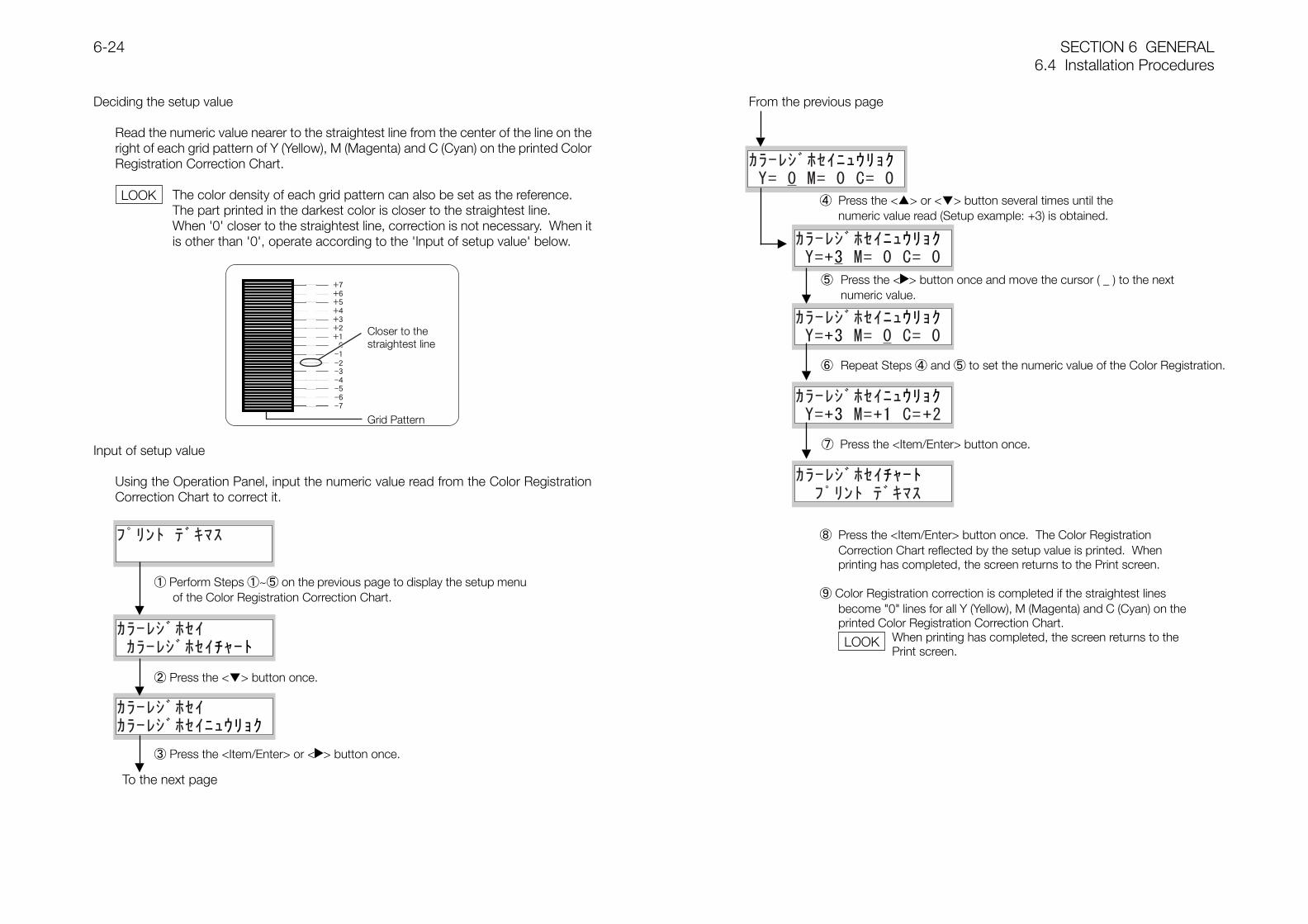
SECTION 6 GENERAL6.4 Installation Procedures
6-24
Deciding the setup value
Read the numeric value nearer to the straightest line from the center of the line on theright of each grid pattern of Y (Yellow), M (Magenta) and C (Cyan) on the printed ColorRegistration Correction Chart.
The color density of each grid pattern can also be set as the reference.The part printed in the darkest color is closer to the straightest line.When '0' closer to the straightest line, correction is not necessary. When itis other than '0', operate according to the 'Input of setup value' below.
Input of setup value
Using the Operation Panel, input the numeric value read from the Color RegistrationCorrection Chart to correct it.
To the next page
From the previous page
① Perform Steps ①~⑤ on the previous page to display the setup menuof the Color Registration Correction Chart.
② Press the <> button once.
③ Press the <Item/Enter> or < > button once.
④ Press the <> or <> button several times until thenumeric value read (Setup example: +3) is obtained.
⑤ Press the < > button once and move the cursor ( _ ) to the nextnumeric value.
⑥ Repeat Steps ④ and ⑤ to set the numeric value of the Color Registration.
⑦ Press the <Item/Enter> button once.
Closer to thestraightest line
Grid Pattern
⑧ Press the <Item/Enter> button once. The Color RegistrationCorrection Chart reflected by the setup value is printed. Whenprinting has completed, the screen returns to the Print screen.
⑨ Color Registration correction is completed if the straightest linesbecome "0" lines for all Y (Yellow), M (Magenta) and C (Cyan) on theprinted Color Registration Correction Chart.
When printing has completed, the screen returns to thePrint screen.
LOOK
LOOK
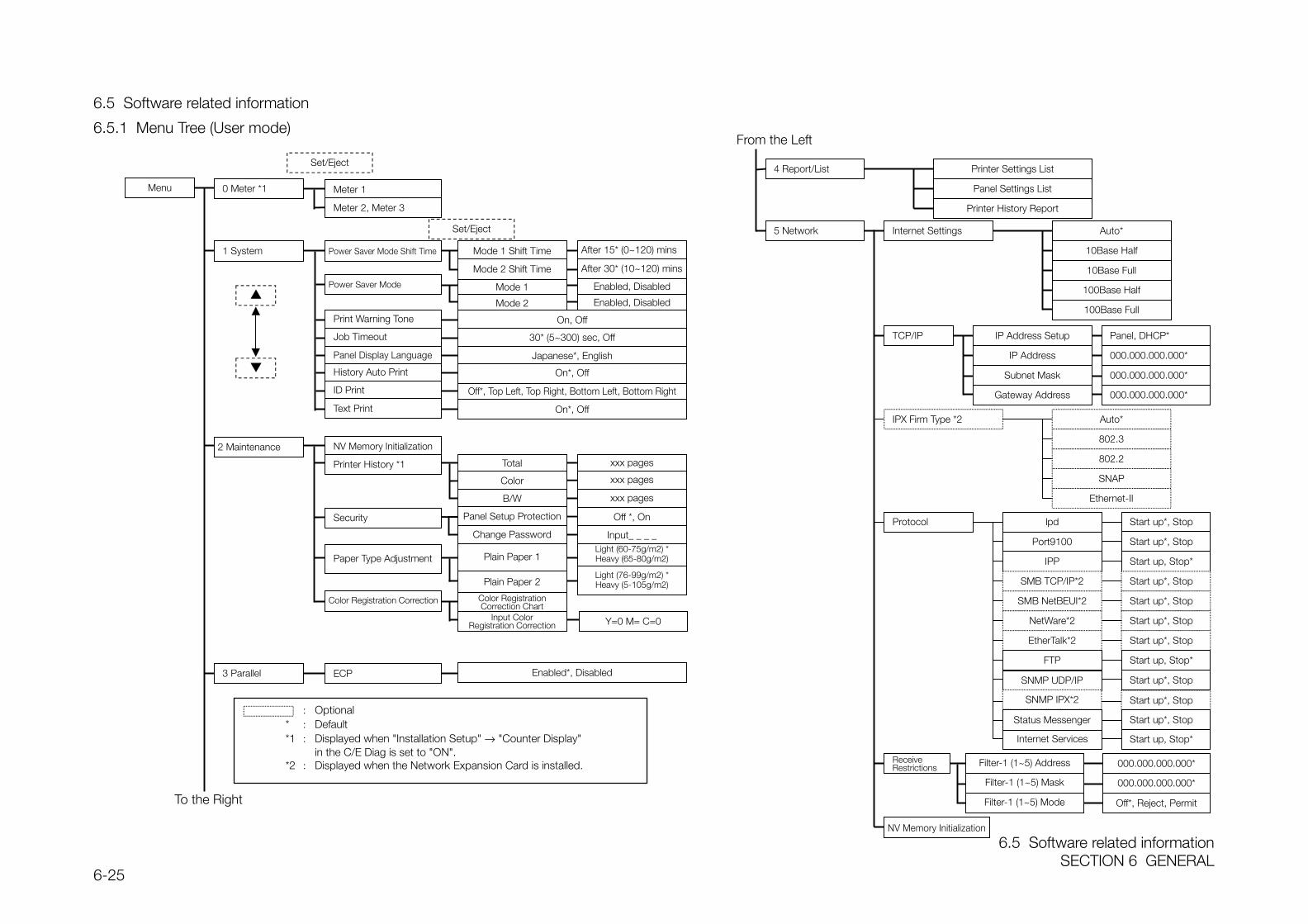
6.5 Software related informationSECTION 6 GENERAL
6-25
6.5 Software related information
6.5.1 Menu Tree (User mode)
Menu
To the Right
: Optional* : Default*1 : Displayed when "Installation Setup" → "Counter Display"
in the C/E Diag is set to "ON".*2 : Displayed when the Network Expansion Card is installed.
From the Left
Printer Settings List
Printer History Report
4 Report/List
Set/Eject
Panel Settings List
Internet Settings Auto*
100Base Full
100Base Half
10Base Full
10Base Half
Protocol lpd
Port9100
IPP
SMB TCP/IP*2
SMB NetBEUI*2
NetWare*2
EtherTalk*2
Start up*, Stop
Auto*
Ethernet-II
SNAP
802.2
802.3
Start up*, Stop
Start up, Stop*
Start up*, Stop
Start up*, Stop
Start up*, Stop
Start up*, Stop
Start up, Stop*FTP
Filter-1 (1~5) Address 000.000.000.000*
0 Meter *1 Meter 1
モード 1 有効、無効モード 1 有効、無効
Mode 2
Mode 1 Shift Time After 15* (0~120) minsPower Saver Mode Shift Time1 System
Enabled, Disabled
On, Off
30* (5~300) sec, Off
Japanese*, English
Off*, Top Left, Top Right, Bottom Left, Bottom Right
On*, Off
On*, Off
Print Warning Tone
Job Timeout
Panel Display Language
History Auto Print
ID Print
Text Print
2 Maintenance NV Memory Initialization
Mode 1Power Saver Mode Enabled, Disabled
After 30* (10~120) minsMode 2 Shift Time
Total xxx pagesPrinter History *1
Color xxx pages
B/W xxx pages
Panel Setup Protection Off *, On
Change Password Input_ _ _ _
Plain Paper 1Light (60-75g/m2) *Heavy (65-80g/m2)
Plain Paper 2Light (76-99g/m2) *Heavy (5-105g/m2)
Security
Paper Type Adjustment
Color Registration Correction Color RegistrationCorrection Chart
Input ColorRegistration Correction Y=0 M= C=0
3 Parallel ECP Enabled*, Disabled
Meter 2, Meter 3
5 Network
TCP/IP IP Address Setup Panel, DHCP*
000.000.000.000*IP Address
Subnet Mask
Gateway Address
000.000.000.000*
000.000.000.000*
IPX Firm Type *2
ReceiveRestrictions
SNMP UDP/IP Start up*, Stop
SNMP IPX*2
Internet Services
Start up*, Stop
Start up, Stop*
Status Messenger Start up*, Stop
000.000.000.000*
Off*, Reject, Permit
Filter-1 (1~5) Mask
Filter-1 (1~5) Mode
NV Memory Initialization
Set/Eject
SECTION 7 ELECTRICAL WIRING DIAGRAMS

ContentsSECTION 7 ELECTRICAL WIRING DIAGRAMS
7-1
Contents
7.1 Plug/Jack Location Index........................................................................................... 2
7.1.1 Printer ................................................................................................................. 2
7.1.2 2Tray Module....................................................................................................... 4
7.2 Plug/Jack Location Drawings..................................................................................... 5
7.2.1 IOT Top ............................................................................................................... 5
7.2.2 IOT Front/RH....................................................................................................... 5
7.2.3 MCU AND HVPS PWB/ESS PWB ....................................................................... 6
7.2.4 PHD ASSY .......................................................................................................... 6
7.2.5 BTR ASSY........................................................................................................... 7
7.2.6 Tray1 ................................................................................................................... 7
7.2.7 2Tray Module....................................................................................................... 8
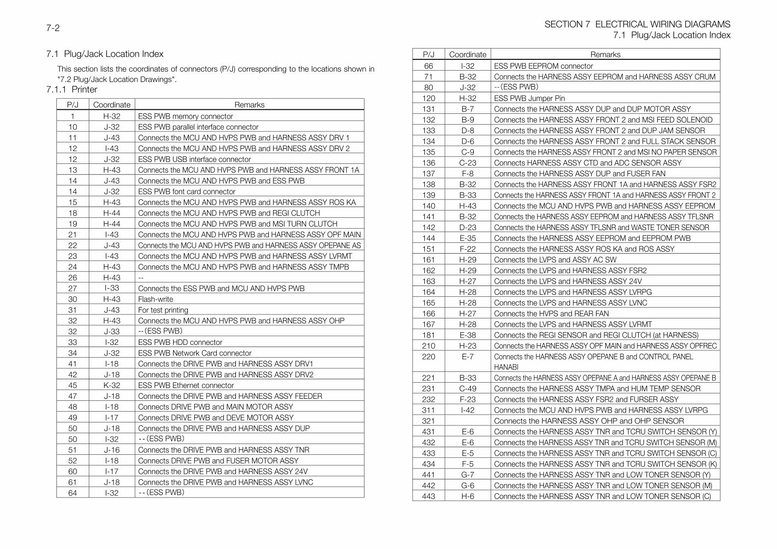
SECTION 7 ELECTRICAL WIRING DIAGRAMS7.1 Plug/Jack Location Index
7-2
7.1 Plug/Jack Location Index
This section lists the coordinates of connectors (P/J) corresponding to the locations shown in"7.2 Plug/Jack Location Drawings".
7.1.1 Printer
P/J Coordinate Remarks1 H-32 ESS PWB memory connector
10 J-32 ESS PWB parallel interface connector11 J-43 Connects the MCU AND HVPS PWB and HARNESS ASSY DRV 112 I-43 Connects the MCU AND HVPS PWB and HARNESS ASSY DRV 212 J-32 ESS PWB USB interface connector13 H-43 Connects the MCU AND HVPS PWB and HARNESS ASSY FRONT 1A14 J-43 Connects the MCU AND HVPS PWB and ESS PWB14 J-32 ESS PWB font card connector15 H-43 Connects the MCU AND HVPS PWB and HARNESS ASSY ROS KA18 H-44 Connects the MCU AND HVPS PWB and REGI CLUTCH19 H-44 Connects the MCU AND HVPS PWB and MSI TURN CLUTCH21 I-43 Connects the MCU AND HVPS PWB and HARNESS ASSY OPF MAIN22 J-43 Connects the MCU AND HVPS PWB and HARNESS ASSY OPEPANE AS23 I-43 Connects the MCU AND HVPS PWB and HARNESS ASSY LVRMT24 H-43 Connects the MCU AND HVPS PWB and HARNESS ASSY TMPB26 H-43 --27 I‐33 Connects the ESS PWB and MCU AND HVPS PWB30 H-43 Flash-write31 J-43 For test printing32 H-43 Connects the MCU AND HVPS PWB and HARNESS ASSY OHP32 J-33 --(ESS PWB)33 I-32 ESS PWB HDD connector34 J-32 ESS PWB Network Card connector41 I-18 Connects the DRIVE PWB and HARNESS ASSY DRV142 J-18 Connects the DRIVE PWB and HARNESS ASSY DRV245 K-32 ESS PWB Ethernet connector47 J-18 Connects the DRIVE PWB and HARNESS ASSY FEEDER48 I-18 Connects DRIVE PWB and MAIN MOTOR ASSY49 I-17 Connects DRIVE PWB and DEVE MOTOR ASSY50 J-18 Connects the DRIVE PWB and HARNESS ASSY DUP50 I-32 ‐‐(ESS PWB)51 J-16 Connects the DRIVE PWB and HARNESS ASSY TNR52 I-18 Connects DRIVE PWB and FUSER MOTOR ASSY60 I-17 Connects the DRIVE PWB and HARNESS ASSY 24V61 J-18 Connects the DRIVE PWB and HARNESS ASSY LVNC64 I-32 ‐‐(ESS PWB)
P/J Coordinate Remarks66 I-32 ESS PWB EEPROM connector71 B-32 Connects the HARNESS ASSY EEPROM and HARNESS ASSY CRUM80 J-32 --(ESS PWB)
120 H-32 ESS PWB Jumper Pin131 B-7 Connects the HARNESS ASSY DUP and DUP MOTOR ASSY132 B-9 Connects the HARNESS ASSY FRONT 2 and MSI FEED SOLENOID133 D-8 Connects the HARNESS ASSY FRONT 2 and DUP JAM SENSOR134 D-6 Connects the HARNESS ASSY FRONT 2 and FULL STACK SENSOR135 C-9 Connects the HARNESS ASSY FRONT 2 and MSI NO PAPER SENSOR136 C-23 Connects HARNESS ASSY CTD and ADC SENSOR ASSY137 F-8 Connects the HARNESS ASSY DUP and FUSER FAN138 B-32 Connects the HARNESS ASSY FRONT 1A and HARNESS ASSY FSR2139 B-33 Connects the HARNESS ASSY FRONT 1A and HARNESS ASSY FRONT 2140 H-43 Connects the MCU AND HVPS PWB and HARNESS ASSY EEPROM141 B-32 Connects the HARNESS ASSY EEPROM and HARNESS ASSY TFLSNR142 D-23 Connects the HARNESS ASSY TFLSNR and WASTE TONER SENSOR144 E-35 Connects the HARNESS ASSY EEPROM and EEPROM PWB151 F-22 Connects the HARNESS ASSY ROS KA and ROS ASSY161 H-29 Connects the LVPS and ASSY AC SW162 H-29 Connects the LVPS and HARNESS ASSY FSR2163 H-27 Connects the LVPS and HARNESS ASSY 24V164 H-28 Connects the LVPS and HARNESS ASSY LVRPG165 H-28 Connects the LVPS and HARNESS ASSY LVNC166 H-27 Connects the HVPS and REAR FAN167 H-28 Connects the LVPS and HARNESS ASSY LVRMT181 E-38 Connects the REGI SENSOR and REGI CLUTCH (at HARNESS)210 H-23 Connects the HARNESS ASSY OPF MAIN and HARNESS ASSY OPFREC220 E-7 Connects the HARNESS ASSY OPEPANE B and CONTROL PANEL
HANABI221 B-33 Connects the HARNESS ASSY OPEPANE A and HARNESS ASSY OPEPANE B231 C-49 Connects the HARNESS ASSY TMPA and HUM TEMP SENSOR232 F-23 Connects the HARNESS ASSY FSR2 and FURSER ASSY311 I-42 Connects the MCU AND HVPS PWB and HARNESS ASSY LVRPG321 Connects the HARNESS ASSY OHP and OHP SENSOR431 E-6 Connects the HARNESS ASSY TNR and TCRU SWITCH SENSOR (Y)432 E-6 Connects the HARNESS ASSY TNR and TCRU SWITCH SENSOR (M)433 E-5 Connects the HARNESS ASSY TNR and TCRU SWITCH SENSOR (C)434 F-5 Connects the HARNESS ASSY TNR and TCRU SWITCH SENSOR (K)441 G-7 Connects the HARNESS ASSY TNR and LOW TONER SENSOR (Y)442 G-6 Connects the HARNESS ASSY TNR and LOW TONER SENSOR (M)443 H-6 Connects the HARNESS ASSY TNR and LOW TONER SENSOR (C)
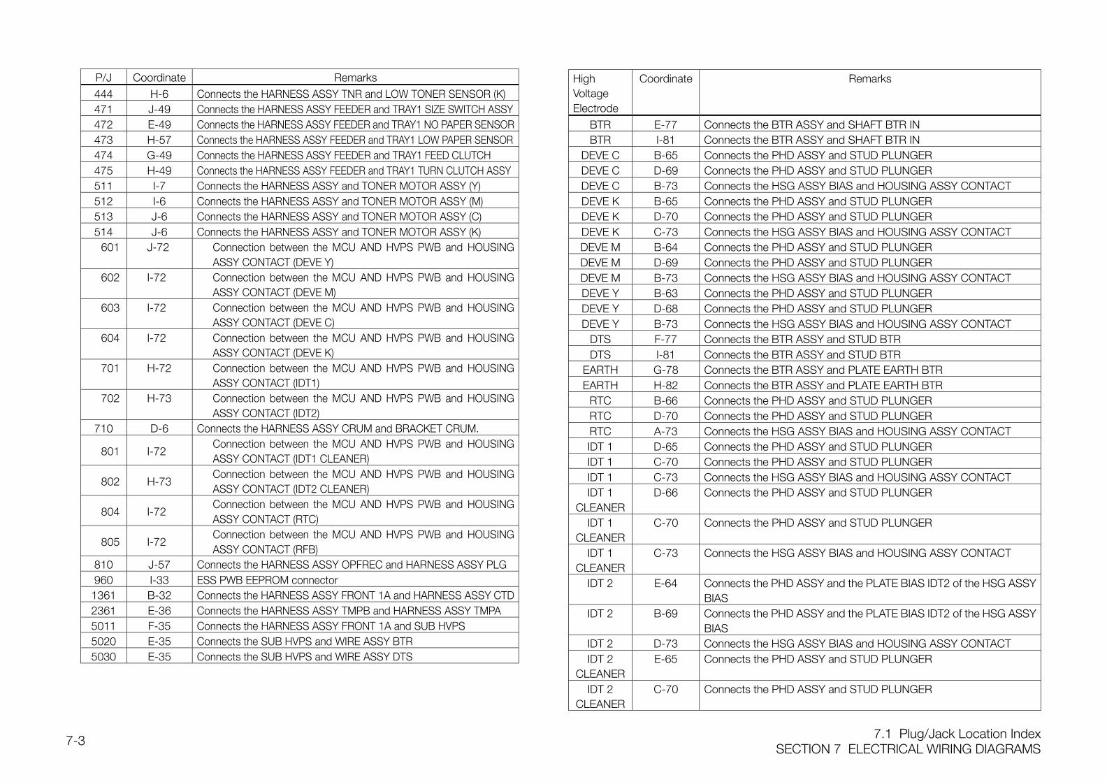
7.1 Plug/Jack Location IndexSECTION 7 ELECTRICAL WIRING DIAGRAMS
7-3
P/J Coordinate Remarks444 H-6 Connects the HARNESS ASSY TNR and LOW TONER SENSOR (K)471 J-49 Connects the HARNESS ASSY FEEDER and TRAY1 SIZE SWITCH ASSY472 E-49 Connects the HARNESS ASSY FEEDER and TRAY1 NO PAPER SENSOR473 H-57 Connects the HARNESS ASSY FEEDER and TRAY1 LOW PAPER SENSOR474 G-49 Connects the HARNESS ASSY FEEDER and TRAY1 FEED CLUTCH475 H-49 Connects the HARNESS ASSY FEEDER and TRAY1 TURN CLUTCH ASSY511 I-7 Connects the HARNESS ASSY and TONER MOTOR ASSY (Y)512 I-6 Connects the HARNESS ASSY and TONER MOTOR ASSY (M)513 J-6 Connects the HARNESS ASSY and TONER MOTOR ASSY (C)514 J-6 Connects the HARNESS ASSY and TONER MOTOR ASSY (K)
601 J-72 Connection between the MCU AND HVPS PWB and HOUSINGASSY CONTACT (DEVE Y)
602 I-72 Connection between the MCU AND HVPS PWB and HOUSINGASSY CONTACT (DEVE M)
603 I-72 Connection between the MCU AND HVPS PWB and HOUSINGASSY CONTACT (DEVE C)
604 I-72 Connection between the MCU AND HVPS PWB and HOUSINGASSY CONTACT (DEVE K)
701 H-72 Connection between the MCU AND HVPS PWB and HOUSINGASSY CONTACT (IDT1)
702 H-73 Connection between the MCU AND HVPS PWB and HOUSINGASSY CONTACT (IDT2)
710 D-6 Connects the HARNESS ASSY CRUM and BRACKET CRUM.
801 I-72Connection between the MCU AND HVPS PWB and HOUSINGASSY CONTACT (IDT1 CLEANER)
802 H-73Connection between the MCU AND HVPS PWB and HOUSINGASSY CONTACT (IDT2 CLEANER)
804 I-72Connection between the MCU AND HVPS PWB and HOUSINGASSY CONTACT (RTC)
805 I-72Connection between the MCU AND HVPS PWB and HOUSINGASSY CONTACT (RFB)
810 J-57 Connects the HARNESS ASSY OPFREC and HARNESS ASSY PLG960 I-33 ESS PWB EEPROM connector1361 B-32 Connects the HARNESS ASSY FRONT 1A and HARNESS ASSY CTD2361 E-36 Connects the HARNESS ASSY TMPB and HARNESS ASSY TMPA5011 F-35 Connects the HARNESS ASSY FRONT 1A and SUB HVPS5020 E-35 Connects the SUB HVPS and WIRE ASSY BTR5030 E-35 Connects the SUB HVPS and WIRE ASSY DTS
HighVoltageElectrode
Coordinate Remarks
BTR E-77 Connects the BTR ASSY and SHAFT BTR INBTR I-81 Connects the BTR ASSY and SHAFT BTR IN
DEVE C B-65 Connects the PHD ASSY and STUD PLUNGERDEVE C D-69 Connects the PHD ASSY and STUD PLUNGERDEVE C B-73 Connects the HSG ASSY BIAS and HOUSING ASSY CONTACTDEVE K B-65 Connects the PHD ASSY and STUD PLUNGERDEVE K D-70 Connects the PHD ASSY and STUD PLUNGERDEVE K C-73 Connects the HSG ASSY BIAS and HOUSING ASSY CONTACTDEVE M B-64 Connects the PHD ASSY and STUD PLUNGERDEVE M D-69 Connects the PHD ASSY and STUD PLUNGERDEVE M B-73 Connects the HSG ASSY BIAS and HOUSING ASSY CONTACTDEVE Y B-63 Connects the PHD ASSY and STUD PLUNGERDEVE Y D-68 Connects the PHD ASSY and STUD PLUNGERDEVE Y B-73 Connects the HSG ASSY BIAS and HOUSING ASSY CONTACT
DTS F-77 Connects the BTR ASSY and STUD BTRDTS I-81 Connects the BTR ASSY and STUD BTR
EARTH G-78 Connects the BTR ASSY and PLATE EARTH BTREARTH H-82 Connects the BTR ASSY and PLATE EARTH BTR
RTC B-66 Connects the PHD ASSY and STUD PLUNGERRTC D-70 Connects the PHD ASSY and STUD PLUNGERRTC A-73 Connects the HSG ASSY BIAS and HOUSING ASSY CONTACTIDT 1 D-65 Connects the PHD ASSY and STUD PLUNGERIDT 1 C-70 Connects the PHD ASSY and STUD PLUNGERIDT 1 C-73 Connects the HSG ASSY BIAS and HOUSING ASSY CONTACTIDT 1
CLEANERD-66 Connects the PHD ASSY and STUD PLUNGER
IDT 1CLEANER
C-70 Connects the PHD ASSY and STUD PLUNGER
IDT 1CLEANER
C-73 Connects the HSG ASSY BIAS and HOUSING ASSY CONTACT
IDT 2 E-64 Connects the PHD ASSY and the PLATE BIAS IDT2 of the HSG ASSYBIAS
IDT 2 B-69 Connects the PHD ASSY and the PLATE BIAS IDT2 of the HSG ASSYBIAS
IDT 2 D-73 Connects the HSG ASSY BIAS and HOUSING ASSY CONTACTIDT 2
CLEANERE-65 Connects the PHD ASSY and STUD PLUNGER
IDT 2CLEANER
C-70 Connects the PHD ASSY and STUD PLUNGER
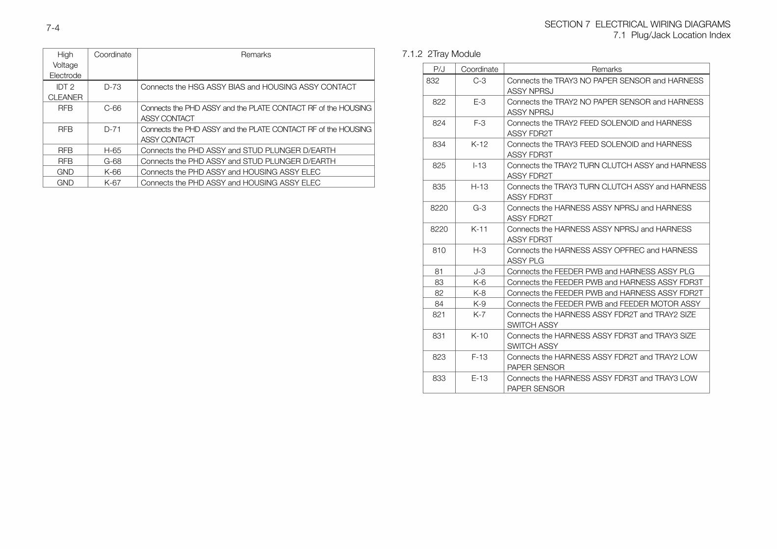
SECTION 7 ELECTRICAL WIRING DIAGRAMS7.1 Plug/Jack Location Index
7-4
HighVoltage
Electrode
Coordinate Remarks
IDT 2CLEANER
D-73 Connects the HSG ASSY BIAS and HOUSING ASSY CONTACT
RFB C-66 Connects the PHD ASSY and the PLATE CONTACT RF of the HOUSINGASSY CONTACT
RFB D-71 Connects the PHD ASSY and the PLATE CONTACT RF of the HOUSINGASSY CONTACT
RFB H-65 Connects the PHD ASSY and STUD PLUNGER D/EARTHRFB G-68 Connects the PHD ASSY and STUD PLUNGER D/EARTHGND K-66 Connects the PHD ASSY and HOUSING ASSY ELECGND K-67 Connects the PHD ASSY and HOUSING ASSY ELEC
7.1.2 2Tray Module
P/J Coordinate Remarks832 C-3 Connects the TRAY3 NO PAPER SENSOR and HARNESS
ASSY NPRSJ822 E-3 Connects the TRAY2 NO PAPER SENSOR and HARNESS
ASSY NPRSJ824 F-3 Connects the TRAY2 FEED SOLENOID and HARNESS
ASSY FDR2T834 K-12 Connects the TRAY3 FEED SOLENOID and HARNESS
ASSY FDR3T825 I-13 Connects the TRAY2 TURN CLUTCH ASSY and HARNESS
ASSY FDR2T835 H-13 Connects the TRAY3 TURN CLUTCH ASSY and HARNESS
ASSY FDR3T8220 G-3 Connects the HARNESS ASSY NPRSJ and HARNESS
ASSY FDR2T8220 K-11 Connects the HARNESS ASSY NPRSJ and HARNESS
ASSY FDR3T810 H-3 Connects the HARNESS ASSY OPFREC and HARNESS
ASSY PLG81 J-3 Connects the FEEDER PWB and HARNESS ASSY PLG83 K-6 Connects the FEEDER PWB and HARNESS ASSY FDR3T82 K-8 Connects the FEEDER PWB and HARNESS ASSY FDR2T84 K-9 Connects the FEEDER PWB and FEEDER MOTOR ASSY
821 K-7 Connects the HARNESS ASSY FDR2T and TRAY2 SIZESWITCH ASSY
831 K-10 Connects the HARNESS ASSY FDR3T and TRAY3 SIZESWITCH ASSY
823 F-13 Connects the HARNESS ASSY FDR2T and TRAY2 LOWPAPER SENSOR
833 E-13 Connects the HARNESS ASSY FDR3T and TRAY3 LOWPAPER SENSOR
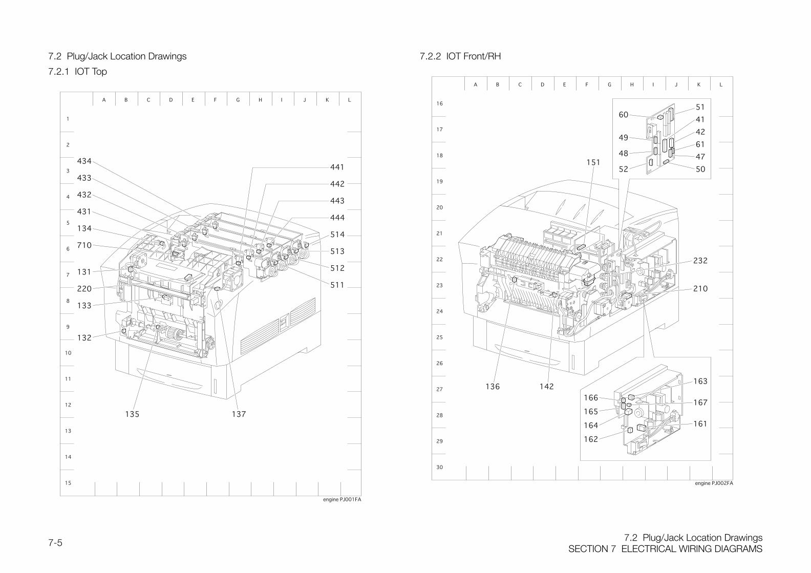
7.2 Plug/Jack Location DrawingsSECTION 7 ELECTRICAL WIRING DIAGRAMS
7-5
7.2 Plug/Jack Location Drawings
7.2.1 IOT Top
7.2.2 IOT Front/RH
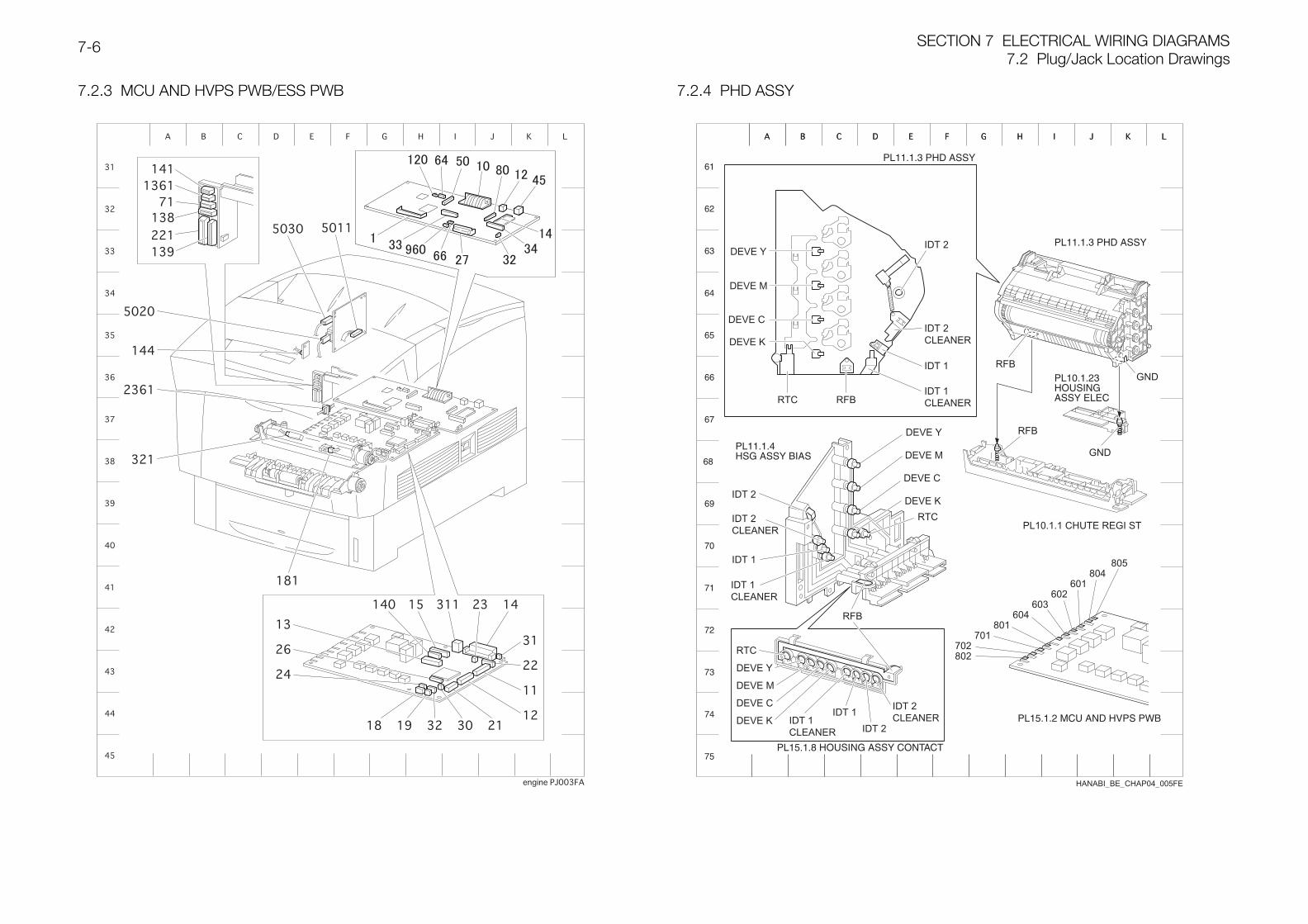
SECTION 7 ELECTRICAL WIRING DIAGRAMS7.2 Plug/Jack Location Drawings
7-6
7.2.3 MCU AND HVPS PWB/ESS PWB 7.2.4 PHD ASSY
HANABI_BE_CHAP04_005FE
IDT 2
IDT 2CLEANER
IDT 1CLEANER
IDT 1
IDT 2
IDT 2CLEANER
IDT 1CLEANER
IDT 1
IDT 2
IDT 2CLEANERIDT 1
CLEANER
IDT 1
RFB
RFB
RTC
RTC
RFB
RFBGND
GND
RTC
DEVE Y
DEVE Y
DEVE M
DEVE M
DEVE C
DEVE C
DEVE K
DEVE K
DEVE Y
DEVE M
DEVE C
DEVE K
805804
801
802
701702
601602
603604
PL11.1.3 PHD ASSY
PL11.1.3 PHD ASSY
PL11.1.4HSG ASSY BIAS
PL15.1.2 MCU AND HVPS PWB
PL15.1.8 HOUSING ASSY CONTACT
PL10.1.23HOUSINGASSY ELEC
PL10.1.1 CHUTE REGI ST
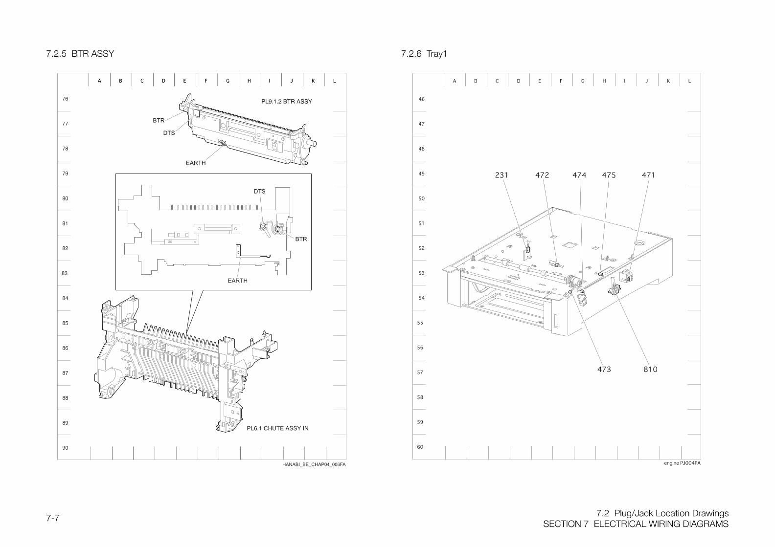
7.2 Plug/Jack Location DrawingsSECTION 7 ELECTRICAL WIRING DIAGRAMS
7-7
7.2.5 BTR ASSY
PL9.1.2 BTR ASSY
PL6.1 CHUTE ASSY IN
7.2.6 Tray1
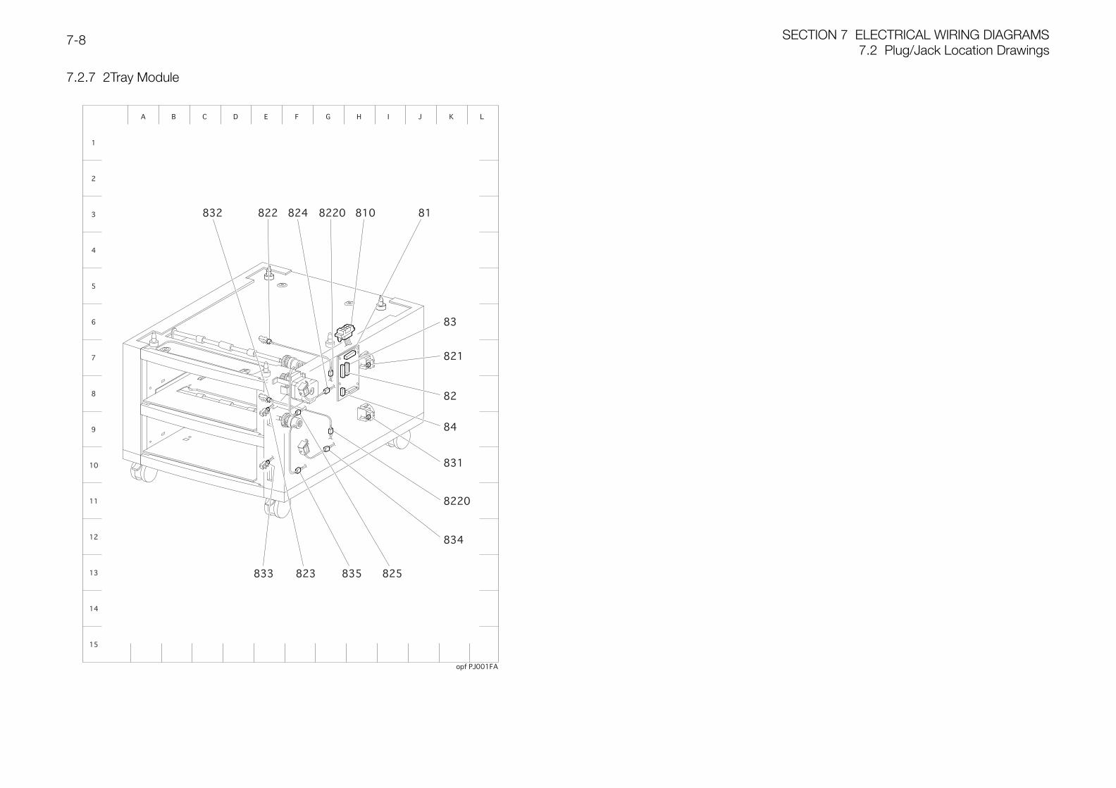
SECTION 7 ELECTRICAL WIRING DIAGRAMS7.2 Plug/Jack Location Drawings
7-8
7.2.7 2Tray Module

SECTION 8 ACCESSORIES
ContentsSECTION 8 ACCESSORIES8-1
Contents
8.1 2-Tray Module.................................................................................................... 2
8.1.1 Install the 2-Tray Module according to the following procedures. .................. 2
8.1.2 Configuring the Printer Driver ....................................................................... 4
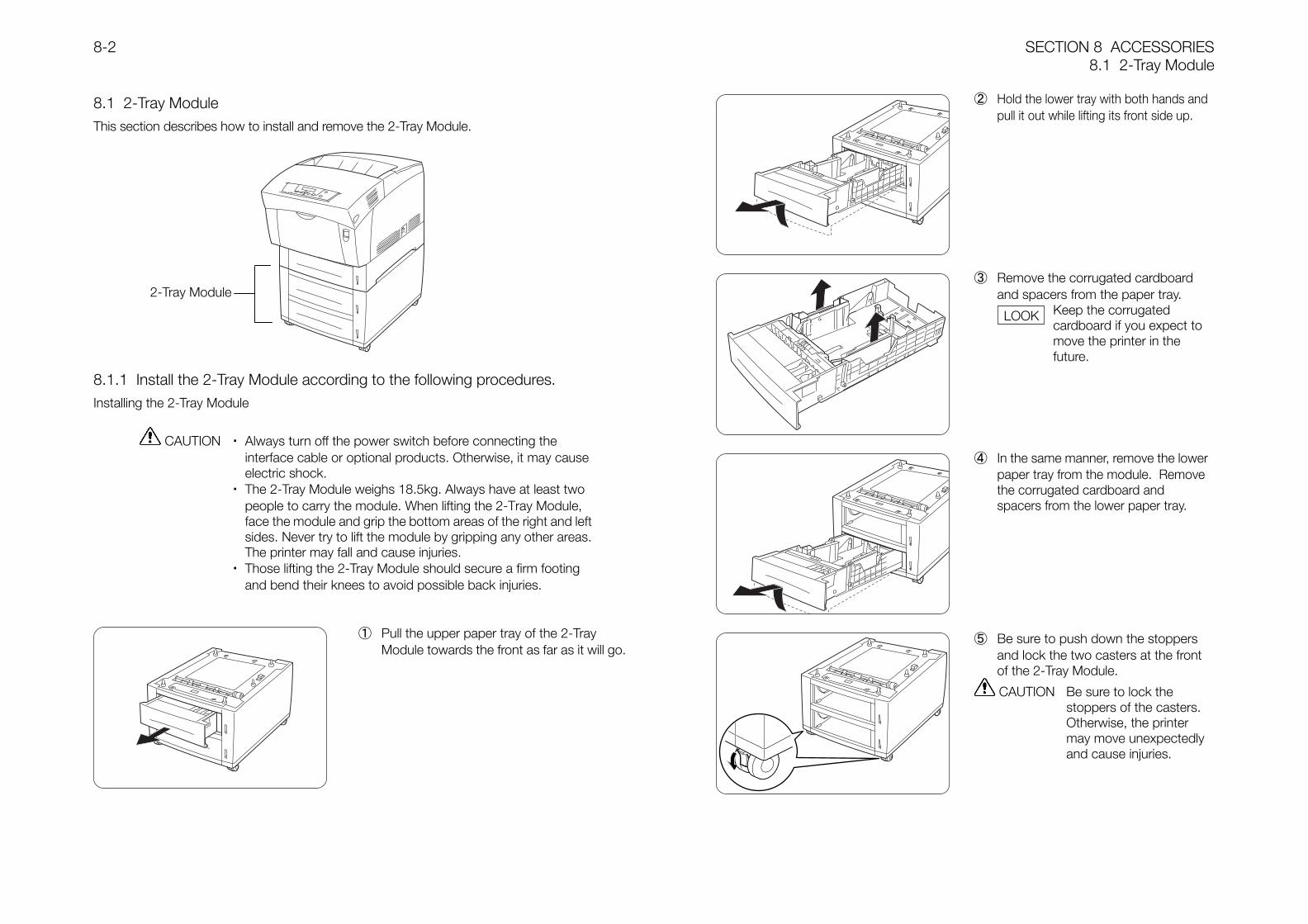
SECTION 8 ACCESSORIES8.1 2-Tray Module
8-2
8.1 2-Tray ModuleThis section describes how to install and remove the 2-Tray Module.
8.1.1 Install the 2-Tray Module according to the following procedures.Installing the 2-Tray Module
CAUTION ・ Always turn off the power switch before connecting theinterface cable or optional products. Otherwise, it may causeelectric shock.
・ The 2-Tray Module weighs 18.5kg. Always have at least twopeople to carry the module. When lifting the 2-Tray Module,face the module and grip the bottom areas of the right and leftsides. Never try to lift the module by gripping any other areas.The printer may fall and cause injuries.
・ Those lifting the 2-Tray Module should secure a firm footingand bend their knees to avoid possible back injuries.
① Pull the upper paper tray of the 2-TrayModule towards the front as far as it will go.
② Hold the lower tray with both hands andpull it out while lifting its front side up.
③ Remove the corrugated cardboardand spacers from the paper tray.
Keep the corrugatedcardboard if you expect tomove the printer in thefuture.
④ In the same manner, remove the lowerpaper tray from the module. Removethe corrugated cardboard andspacers from the lower paper tray.
⑤ Be sure to push down the stoppersand lock the two casters at the frontof the 2-Tray Module.
CAUTION Be sure to lock thestoppers of the casters.Otherwise, the printermay move unexpectedlyand cause injuries.
2-Tray Module
LOOK
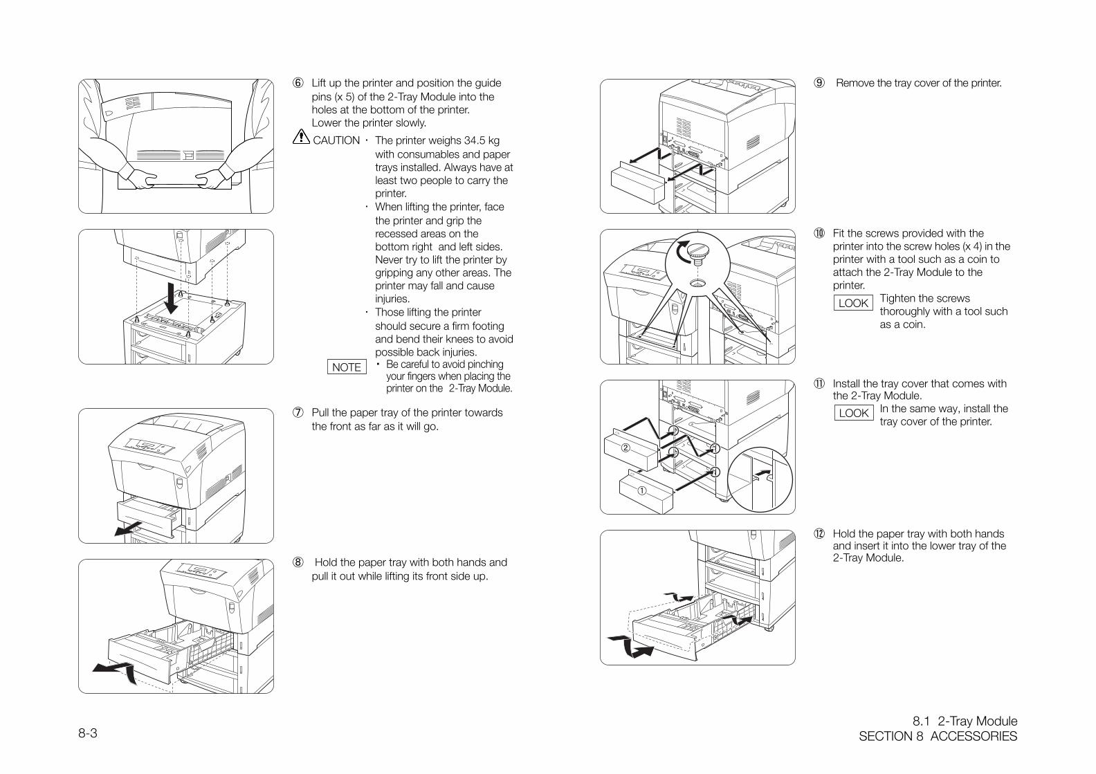
8.1 2-Tray ModuleSECTION 8 ACCESSORIES8-3
⑥ Lift up the printer and position the guidepins (x 5) of the 2-Tray Module into theholes at the bottom of the printer.Lower the printer slowly.
CAUTION ・ The printer weighs 34.5 kgwith consumables and papertrays installed. Always have atleast two people to carry theprinter.
・ When lifting the printer, facethe printer and grip therecessed areas on thebottom right and left sides.Never try to lift the printer bygripping any other areas. Theprinter may fall and causeinjuries.
・ Those lifting the printershould secure a firm footingand bend their knees to avoidpossible back injuries.
・ Be careful to avoid pinching your fingers when placing the printer on the 2-Tray Module.
⑦ Pull the paper tray of the printer towardsthe front as far as it will go.
⑧ Hold the paper tray with both hands andpull it out while lifting its front side up.
⑨ Remove the tray cover of the printer.
⑩ Fit the screws provided with theprinter into the screw holes (x 4) in theprinter with a tool such as a coin toattach the 2-Tray Module to theprinter. Tighten the screws
thoroughly with a tool suchas a coin.
⑪ Install the tray cover that comes withthe 2-Tray Module.
In the same way, install thetray cover of the printer.
⑫ Hold the paper tray with both handsand insert it into the lower tray of the2-Tray Module.
NOTE
LOOK
LOOK
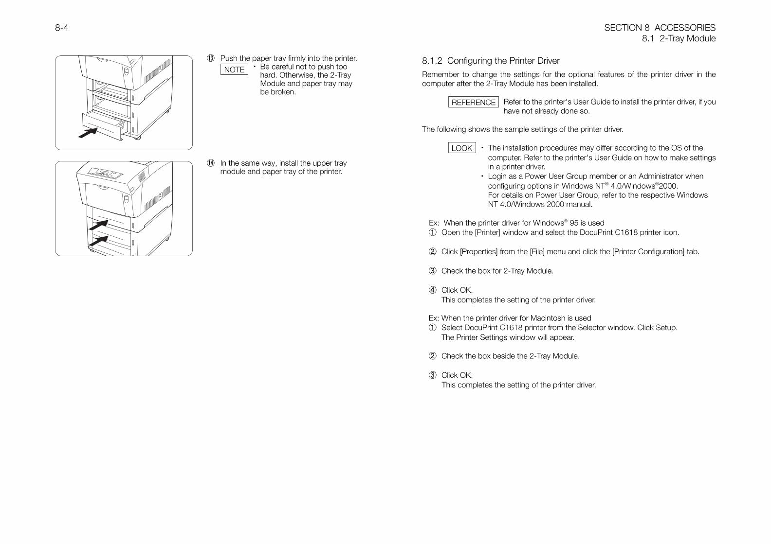
SECTION 8 ACCESSORIES8.1 2-Tray Module
8-4
8.1.2 Configuring the Printer DriverRemember to change the settings for the optional features of the printer driver in thecomputer after the 2-Tray Module has been installed.
Refer to the printer's User Guide to install the printer driver, if youhave not already done so.
The following shows the sample settings of the printer driver.
・ The installation procedures may differ according to the OS of thecomputer. Refer to the printer's User Guide on how to make settingsin a printer driver.
・ Login as a Power User Group member or an Administrator whenconfiguring options in Windows NT® 4.0/Windows®2000.For details on Power User Group, refer to the respective WindowsNT 4.0/Windows 2000 manual.
Ex: When the printer driver for Windows 95 is used① Open the [Printer] window and select the DocuPrint C1618 printer icon.
② Click [Properties] from the [File] menu and click the [Printer Configuration] tab.
③ Check the box for 2-Tray Module.
④ Click OK.This completes the setting of the printer driver.
Ex: When the printer driver for Macintosh is used① Select DocuPrint C1618 printer from the Selector window. Click Setup.
The Printer Settings window will appear.
② Check the box beside the 2-Tray Module.
③ Click OK.This completes the setting of the printer driver.
⑬ Push the paper tray firmly into the printer.・ Be careful not to push too
hard. Otherwise, the 2-TrayModule and paper tray maybe broken.
⑭ In the same way, install the upper traymodule and paper tray of the printer.
NOTE
REFERENCE
LOOK
Recommended