Embed Size (px)
Citation preview
Models<Indoor Units>• In-the-Ceiling Type
RPI-0.8FSG1 RPI-2.5FSG1 RPI-8FSG1
RPI-1.0FSG1 RPI-3.0FSG1 RPI-10FSG1RPI-1.5FSG1 RPI-4.0FSG1
RPI-2.0FSG1 RPI-5.0FSG1
• 4-Way Cassette TypeRCI-1.0FSG2 RCI-2.5FSG2 RCI-5.0FSG2
RCI-1.5FSG2 RCI-3.0FSG2
RCI-2.0FSG2 RCI-4.0FSG2
• 2-Way Cassette TypeRCD-1.0FSG1 RCD-2.5FSG1 RCD-5.0FSG1
RCD-1.5FSG1 RCD-3.0FSG1
RCD-2.0FSG1 RCD-4.0FSG1
• Wall TypeRPK-1.0FSGM RPK-2.0FSGM
RPK-1.5FSGM RPK-2.3FSGM
• Floor TypeRPF-1.0FSG(E) RPF-1.5FSG(E)
• Floor Concealed TypeRPFI-1.0FSG(E) RPFI-1.5FSG(E)
• Ceiling TypeRPC-2.0FSG1 RPC-3.0FSG1 RPC-5.0FSG1
RPC-2.5FSG1 RPC-4.0FSG1
<Outdoor Units>• FSG(1) Series
RAS-5FSG RAS-16FSG RAS-24FSG1
RAS-8FSG RAS-20FSG RAS-30FSG1
RAS-10FSG
• FS3, FS5 SeriesRAS-5FS3 RAS-16FS3 RAS-24FS5
RAS-8FS3 RAS-20FS3 RAS-30FS5
RAS-10FS3
• FXG SeriesRAS-8FXG RAS-10FXG
• FX3 SeriesRAS-8FX3 RAS-10FX3
<System Equipment>• Total Heat Exchangers
KPI-2521 KPI-5021 KPI-8021 KPI-10021
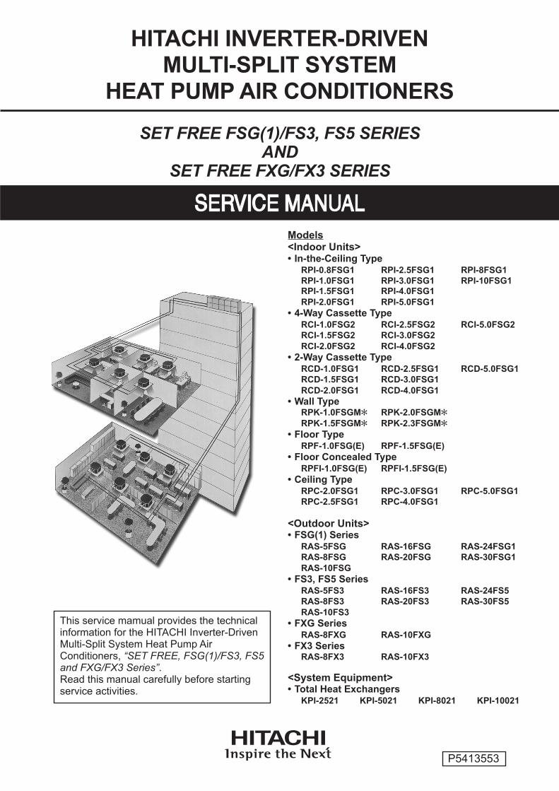
This service mamual provides the technicalinformation for the HITACHI Inverter-DrivenMulti-Split System Heat Pump AirConditioners, “SET FREE, FSG(1)/FS3, FS5and FXG/FX3 Series”.Read this manual carefully before startingservice activities.
HITACHI INVERTER-DRIVENMULTI-SPLIT SYSTEM
HEAT PUMP AIR CONDITIONERS
SET FREE FSG(1)/FS3, FS5 SERIESAND
SET FREE FXG/FX3 SERIES
P5413553

- CONTENTS -No. Page
1. TROUBLESHOOTING ............................................................................................................................... 1-1
1.1 Initial Troubleshooting ........................................................................................................................ 1-1
1.1.1 Rotary Switch and Dip Switch Setting .......................................................................................... 1-1
1.1.2 Checking of Electrical Wiring ........................................................................................................ 1-5
1.1.3 Checking by 7-Segment Display ................................................................................................. 1-10
1.1.4 Emergency Operation when Inverter Compressor is Damaged ................................................... 1-11
1.1.5 Failure of Power Supply to Indoor Unit and Remote Control Switch ............................................ 1-13
1.1.6 Abnormal Transmission between Remote Control Switch and Indoor Unit .................................. 1-14
1.1.7 Abnormalities of Devices .............................................................................................................. 1-15
1.2 Troubleshooting Procedure ................................................................................................................ 1-23
1.2.1 Alarm Code Table ......................................................................................................................... 1-23
1.2.2 Troubleshooting by Alarm Code ................................................................................................... 1-24
1.2.3 Troubleshooting in Check Mode by Remote Control Switch ........................................................ 1-79
1.2.4 Troubleshooting by 7-Segment Display ........................................................................................ 1-85
1.2.5 Function of RSW, DSWs and LEDs .............................................................................................. 1-94
1.3 Procedure of Checking Each Main Parts ........................................................................................... 1-103
1.3.1 Self-Checking of PCBs using Remote Control Switch .................................................................. 1-103
1.3.2 Self-Checking of Remote Control Switch ..................................................................................... 1-105
1.3.3 Self-Checking of Indoor Unit PCB
(Except for: RCI, RCD, RPI (0.8 to 5.0HP), RPC (After Alteration) and KPI) .............................. 1-107
1.3.4 Self-Checking of 7-Day Timer (PSC-3T) ...................................................................................... 1-109
1.3.5 Self-Checking of Central Station (PSC-3S1) ................................................................................ 1-110
1.3.6 Procedure of Checking Other Main Parts ..................................................................................... 1-111
1.4 Test Run ............................................................................................................................................. 1-125
1.4.1 Test Run Mode by Remote Control Switch ................................................................................... 1-125
1.4.2 Test Run Mode by Outdoor Unit ................................................................................................... 1-126
1.4.3 Checking List (FSG and FS3 Series) ........................................................................................... 1-127
- CONTENTS -No. Page
2. SERVICING ................................................................................................................................................ 2-1
2.1 Outdoor Unit ....................................................................................................................................... 2-1
2.1.1 Removing Air Intake Grille ............................................................................................................ 2-1
2.1.2 Removing Front Service Panel ..................................................................................................... 2-2
2.1.3 Removing Fan Guard Nets ........................................................................................................... 2-3
2.1.4 Removing Outdoor Fan ................................................................................................................ 2-4
2.1.5 Removing Compressor (RAS-5FSG and RAS-5FS3) .................................................................. 2-6
2.1.6 Removing Compressors
(RAS-8FSG, RAS-10FSG, RAS-16FSG, RAS-20FSG, RAS-8FS3, RAS-10FS3, RAS-16FS3,
RAS-20FS3, RAS-8FXG, RAS-10FXG, RAS-8FX3 and RAS-10FX3) ........................................ 2-10
2.1.7 Removing Compressors for MC1 and MC2
(RAS-24FSG1, RAS-30FSG1, RAS-24FS5 and RAS-30FS5) ..................................................... 2-15
2.1.8 Removing Compressors for MC3 and MC4
(RAS-24FSG1, RAS-30FSG1, RAS-24FS5 and RAS-30FS5) ..................................................... 2-19
2.1.9 Removing High Pressure Switch, High Pressure Sensor and Low Pressure Sensor .................. 2-23
2.1.10 Removing Coil for Reversing Valve Coil ....................................................................................... 2-26
2.1.11 Removing Coil for Solenoid Valve Coil ......................................................................................... 2-27
2.1.12 Removing Thermistor for Liquid Pipe ........................................................................................... 2-28
2.1.13 Removing Reversing Valve (RAS-5FSG, RAS-8FSG, RAS-10FSG, RAS-16FSG, RAS-20FSG,
RAS-5FS3, RAS-8FS3, RAS-10FS3, RAS-16FS3, RAS-20FS3, RAS-8FXG, RAS-10FXG,
RAS-8FX3 and RAS-10FX3) ........................................................................................................ 2-29
2.1.14 Removing Reversing Valve (RAS-24FSG1, RAS-30FSG1, RAS-24FS5 and RAS-30FS5) ......... 2-30
2.1.15 Removing Electrical Components (RAS-5FSG, RAS-8FSG, RAS-10FSG, RAS-16FSG,
RAS-20FSG, RAS-5FS3, RAS-8FS3, RAS-10FS3, RAS-16FS3, RAS-20FS3, RAS-8FXG,
RAS-10FXG, RAS-8FX3 and RAS-10FX3) .................................................................................. 2-31
2.1.16 Removing Electrical Components
(RAS-24FSG1, RAS-30FSG1, RAS-24FS5 and RAS-30FS5) ..................................................... 2-33
2.2 In-the-Ceiling Type (RPI-0.8FSG1 to RPI-5.0FSG1) ......................................................................... 2-37
2.2.1 Removing Long Life Filter ............................................................................................................. 2-37
2.2.2 Removing Printed Circuit Board (PCB) ........................................................................................ 2-37
2.2.3 Removing Indoor Fan and Fan Motor ........................................................................................... 2-39
2.2.4 Removing Thermistor for Liquid Piping and Gas Piping ............................................................... 2-46
2.2.5 Removing Electronic Expansion Valve Coil .................................................................................. 2-47
2.2.6 Removing Float Switch ................................................................................................................. 2-47
2.2.7 Removing Drain Pump ................................................................................................................. 2-48
2.2.8 Removing Drain Pan .................................................................................................................... 2-49
2.3 In-the-Ceiling Type (RPI-8FSG1 and RPI-10FSG1) .......................................................................... 2-51
2.3.1 Removing Long Life Filter ............................................................................................................. 2-51
2.3.2 Removing Printed Circuit Board (PCB) ........................................................................................ 2-51
2.3.3 Removing Indoor Fan and Fan Motor ........................................................................................... 2-52
2.3.4 Removing Electronic Expansion Valve and Thermistors .............................................................. 2-54
- CONTENTS -No. Page
2.4 4-Way Cassette Type ......................................................................................................................... 2-55
2.4.1 Removing Long Life Filter ............................................................................................................. 2-55
2.4.2 Removing Air Intake Grille ............................................................................................................ 2-55
2.4.3 Removing Electrical Box Cover .................................................................................................... 2-56
2.4.4 Removing Optional Air Panel ........................................................................................................ 2-56
2.4.5 Removing Fan Runner and Fan Motor ......................................................................................... 2-57
2.4.6 Removing Bell-Mouth ................................................................................................................... 2-58
2.4.7 Removing Printed Circuit Board (PCB) ........................................................................................ 2-59
2.4.8 Removing Drain Pan .................................................................................................................... 2-60
2.4.9 Removing Drain-Up Mechanism ................................................................................................... 2-61
2.4.10 Removing Float Switch ................................................................................................................. 2-61
2.4.11 Removing Thermistors for Liquid Pipe and Gas Pipe ................................................................... 2-62
2.4.12 Removing Electronic Expansion Valve Coil .................................................................................. 2-63
2.4.13 Removing Automatic Louver Motor .............................................................................................. 2-65
2.5 2-Way Cassette Type ......................................................................................................................... 2-66
2.5.1 Removing Long Life Filter and Air Intake Grille ............................................................................ 2-66
2.5.2 Removing Electrical Box Cover .................................................................................................... 2-66
2.5.3 Removing Optional Air Panel ........................................................................................................ 2-67
2.5.4 Removing Fan Runner and Fan Motor ......................................................................................... 2-68
2.5.5 Removing Printed Circuit Board (PCB) ........................................................................................ 2-70
2.5.6 Removing Float Switch ................................................................................................................. 2-71
2.5.7 Removing Drain-Up Mechanism ................................................................................................... 2-72
2.5.8 Removing Drain Pan .................................................................................................................... 2-73
2.5.9 Removing Thermistors for Liquid and Gas Pipes ......................................................................... 2-74
2.5.10 Removing Electronic Expansion Valve Coil .................................................................................. 2-75
2.5.11 Removing Automatic Louver Motor .............................................................................................. 2-77
2.6 Wall Type ........................................................................................................................................... 2-79
2.6.1 Removing Air Filter ....................................................................................................................... 2-79
2.6.2 Removing Front Panel .................................................................................................................. 2-80
2.6.3 Removing Motor for Automatic Louver ......................................................................................... 2-82
2.6.4 Removing Thermistors for Liquid Pipe, Gas Pipe, Discharge Air and Suction Air ........................ 2-83
2.6.5 Removing Electrical Box Cover .................................................................................................... 2-85
2.6.6 Removing Indoor PCB .................................................................................................................. 2-86
2.6.7 Removing Drain Pan .................................................................................................................... 2-87
2.6.8 Removing Heat Exchanger ........................................................................................................... 2-88
2.6.9 Removing Fan and Fan Motor ...................................................................................................... 2-90
2.6.10 Removing Electronic Expansion Valve Coil .................................................................................. 2-92
2.7 Floor Type .......................................................................................................................................... 2-94
2.7.1 Removing Air Intake Grille ............................................................................................................ 2-94
2.7.2 Removing Air Filter ....................................................................................................................... 2-94
2.7.3 Removing Discharge Air Grille ...................................................................................................... 2-95
2.7.4 Removing Front Cover ................................................................................................................. 2-95
2.7.5 Removing Fan Motor .................................................................................................................... 2-96
2.7.6 Removing Printed Circuit Board (PCB) ........................................................................................ 2-98
2.7.7 Removing Thermistors for Liquid Pipe and Gas Pipe ................................................................... 2-100
- CONTENTS -No. Page
2.8 Floor Concealed Type ........................................................................................................................ 2-102
2.8.1 Removing Air Filter ....................................................................................................................... 2-102
2.8.2 Removing Front Covers ................................................................................................................ 2-102
2.8.3 Removing Fan Motor .................................................................................................................... 2-103
2.8.4 Removing Printed Circuit Board (PCB) ........................................................................................ 2-103
2.8.5 Removing Thermistors for Liquid Pipe and Gas Pipe ................................................................... 2-103
2.9 Ceiling Type ....................................................................................................................................... 2-104
2.9.1 Removing Air Filter and Air Intake Grille ....................................................................................... 2-104
2.9.2 Removing Side Cover ................................................................................................................... 2-104
2.9.3 Removing Discharge Air Grille ...................................................................................................... 2-105
2.9.4 Removing Fan Motor .................................................................................................................... 2-106
2.9.5 Removing Bearing ........................................................................................................................ 2-108
2.9.6 Removing Coupling ...................................................................................................................... 2-108
2.9.7 Removing Automatic Louver Motor .............................................................................................. 2-109
2.9.8 Removing Thermistors for Liquid Pipe and Gas Pipe, and Electronic Expansion Valve Coil ....... 2-109
2.9.9 Checking Procedures for Electronic Expansion Valve Coil .......................................................... 2-110
2.9.10 Removing Printed Circuit Board (PCB) ........................................................................................ 2-111
2.10 Total Heat Exchanger ......................................................................................................................... 2-112
2.10.1 Structure ....................................................................................................................................... 2-112
2.10.2 Removing Electrical Parts ............................................................................................................ 2-112
2.10.3 Removing Air Filter and Total Heat Exchanger Element ............................................................... 2-113
2.10.4 Removing Fan Motor .................................................................................................................... 2-114
2.10.5 Air Filter Cleaning ......................................................................................................................... 2-115
2.10.6 Total Heat Exchanger Cleaning .................................................................................................... 2-115
2.11 Cleaning Indoor Unit Heat Exchanger ............................................................................................... 2-116
2.11.1 Required Tools for Cleaning (for All Indoor Units) ........................................................................ 2-116
2.11.2 In-the-Ceiling Type ....................................................................................................................... 2-117
2.11.3 Cleaning 4-Way Cassette Type Indoor Unit .................................................................................. 2-120
2.11.4 Cleaning 2-Way Cassette Type Indoor Unit .................................................................................. 2-124
2.11.5 Cleaning Wall Type Indoor Unit .................................................................................................... 2-127
2.11.6 Cleaning Floor Type and Floor Concealed Type Indoor Unit ........................................................ 2-128
2.11.7 Cleaning Ceiling Type Indoor Unit ................................................................................................ 2-131
2.12 Collecting Refrigerant for Replacing Indoor Unit ................................................................................ 2-133
3. MAIN PARTS .............................................................................................................................................. 3-1
3.1 Inverter ............................................................................................................................................... 3-1
3.1.1 Specifications of Inverter (For 380/415V, 50Hz and 380V, 60Hz Power Source) ......................... 3-1
3.1.2 Specifications of Inverter (For 220V, 60Hz Power Source) .......................................................... 3-3
3.1.3 Arrangement of Inverter Power Unit ............................................................................................. 3-5
3.1.4 Inverter Time Chart ....................................................................................................................... 3-9
3.1.5 Protective Function ....................................................................................................................... 3-10
3.1.6 Overload Control .......................................................................................................................... 3-11
3.2 AC Chopper ....................................................................................................................................... 3-12
3.3 Auto-Louver Mechanism .................................................................................................................... 3-14
3.3.1 4-Way Cassette Type ................................................................................................................... 3-14
3.3.2 2-Way Cassette Type ................................................................................................................... 3-15
3.3.3 Ceiling Type ..................................................................................................................................... 3-16
3.4 Scroll Compressor ............................................................................................................................. 3-17
3.4.1 Reliable Mechanism for Low Vibration and Low Sound ............................................................... 3-17
3.4.2 Principle of Compression .............................................................................................................. 3-17
3.4.3 Structure ....................................................................................................................................... 3-18
3.5 Thermistor .......................................................................................................................................... 3-20
3.5.1 Thermistor for Indoor Unit ............................................................................................................. 3-20
3.5.2 Thermistor for Outdoor Unit .......................................................................................................... 3-21
3.6 Electronic Expansion Valve ................................................................................................................ 3-23
3.6.1 Electronic Expansion Valve for Outdoor Units .............................................................................. 3-23
3.6.2 Electronic Expansion Valve for Indoor Units ................................................................................. 3-24
3.7 Pressure Sensor ................................................................................................................................ 3-25
3.8 High Pressure Protection Device ....................................................................................................... 3-26
3.9 Noise Filter (NF) ................................................................................................................................. 3-27
3.10 Capacitor (CB1, CB2) ........................................................................................................................ 3-29
3.11 Reactor (DCL) .................................................................................................................................... 3-29
- CONTENTS -No. Page
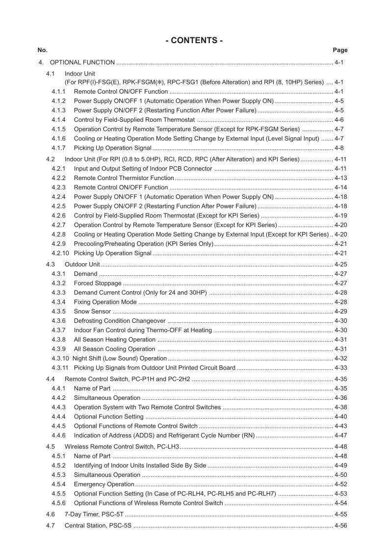
4. OPTIONAL FUNCTION .............................................................................................................................. 4-1
4.1 Indoor Unit
(For RPF(I)-FSG(E), RPK-FSGM(), RPC-FSG1 (Before Alteration) and RPI (8, 10HP) Series) .... 4-1
4.1.1 Remote Control ON/OFF Function ............................................................................................... 4-1
4.1.2 Power Supply ON/OFF 1 (Automatic Operation When Power Supply ON) .................................. 4-5
4.1.3 Power Supply ON/OFF 2 (Restarting Function After Power Failure) ............................................ 4-5
4.1.4 Control by Field-Supplied Room Thermostat ............................................................................... 4-6
4.1.5 Operation Control by Remote Temperature Sensor (Except for RPK-FSGM Series) .................. 4-7
4.1.6 Cooling or Heating Operation Mode Setting Change by External Input (Level Signal Input) ....... 4-7
4.1.7 Picking Up Operation Signal ......................................................................................................... 4-8
4.2 Indoor Unit (For RPI (0.8 to 5.0HP), RCI, RCD, RPC (After Alteration) and KPI Series) ................... 4-11
4.2.1 Input and Output Setting of Indoor PCB Connector ..................................................................... 4-11
4.2.2 Remote Control Thermistor Function............................................................................................ 4-13
4.2.3 Remote Control ON/OFF Function ............................................................................................... 4-14
4.2.4 Power Supply ON/OFF 1 (Automatic Operation When Power Supply ON) .................................. 4-18
4.2.5 Power Supply ON/OFF 2 (Restarting Function After Power Failure) ............................................ 4-18
4.2.6 Control by Field-Supplied Room Thermostat (Except for KPI Series) .......................................... 4-19
4.2.7 Operation Control by Remote Temperature Sensor (Except for KPI Series) ................................ 4-20
4.2.8 Cooling or Heating Operation Mode Setting Change by External Input (Except for KPI Series) .. 4-20
4.2.9 Precooling/Preheating Operation (KPI Series Only) ..................................................................... 4-21
4.2.10 Picking Up Operation Signal ......................................................................................................... 4-21
4.3 Outdoor Unit ....................................................................................................................................... 4-25
4.3.1 Demand ........................................................................................................................................ 4-27
4.3.2 Forced Stoppage .......................................................................................................................... 4-27
4.3.3 Demand Current Control (Only for 24 and 30HP) ........................................................................ 4-28
4.3.4 Fixing Operation Mode ................................................................................................................. 4-28
4.3.5 Snow Sensor ................................................................................................................................ 4-29
4.3.6 Defrosting Condition Changeover ................................................................................................ 4-30
4.3.7 Indoor Fan Control during Thermo-OFF at Heating ..................................................................... 4-30
4.3.8 All Season Heating Operation ...................................................................................................... 4-31
4.3.9 All Season Cooling Operation ...................................................................................................... 4-31
4.3.10 Night Shift (Low Sound) Operation ................................................................................................ 4-32
4.3.11 Picking Up Signals from Outdoor Unit Printed Circuit Board ........................................................ 4-33
4.4 Remote Control Switch, PC-P1H and PC-2H2 .................................................................................. 4-35
4.4.1 Name of Part ................................................................................................................................ 4-35
4.4.2 Simultaneous Operation ............................................................................................................... 4-36
4.4.3 Operation System with Two Remote Control Switches ................................................................ 4-38
4.4.4 Optional Function Setting ............................................................................................................. 4-40
4.4.5 Optional Functions of Remote Control Switch .............................................................................. 4-43
4.4.6 Indication of Address (ADDS) and Refrigerant Cycle Number (RN) ............................................. 4-47
4.5 Wireless Remote Control Switch, PC-LH3 ......................................................................................... 4-48
4.5.1 Name of Part ................................................................................................................................ 4-48
4.5.2 Identifying of Indoor Units Installed Side By Side ......................................................................... 4-49
4.5.3 Simultaneous Operation ............................................................................................................... 4-50
4.5.4 Emergency Operation ................................................................................................................... 4-52
4.5.5 Optional Function Setting (In Case of PC-RLH4, PC-RLH5 and PC-RLH7) ................................ 4-53
4.5.6 Optional Functions of Wireless Remote Control Switch ............................................................... 4-54
4.6 7-Day Timer, PSC-5T ......................................................................................................................... 4-55
4.7 Central Station, PSC-5S .................................................................................................................... 4-56
- CONTENTS -No. Page
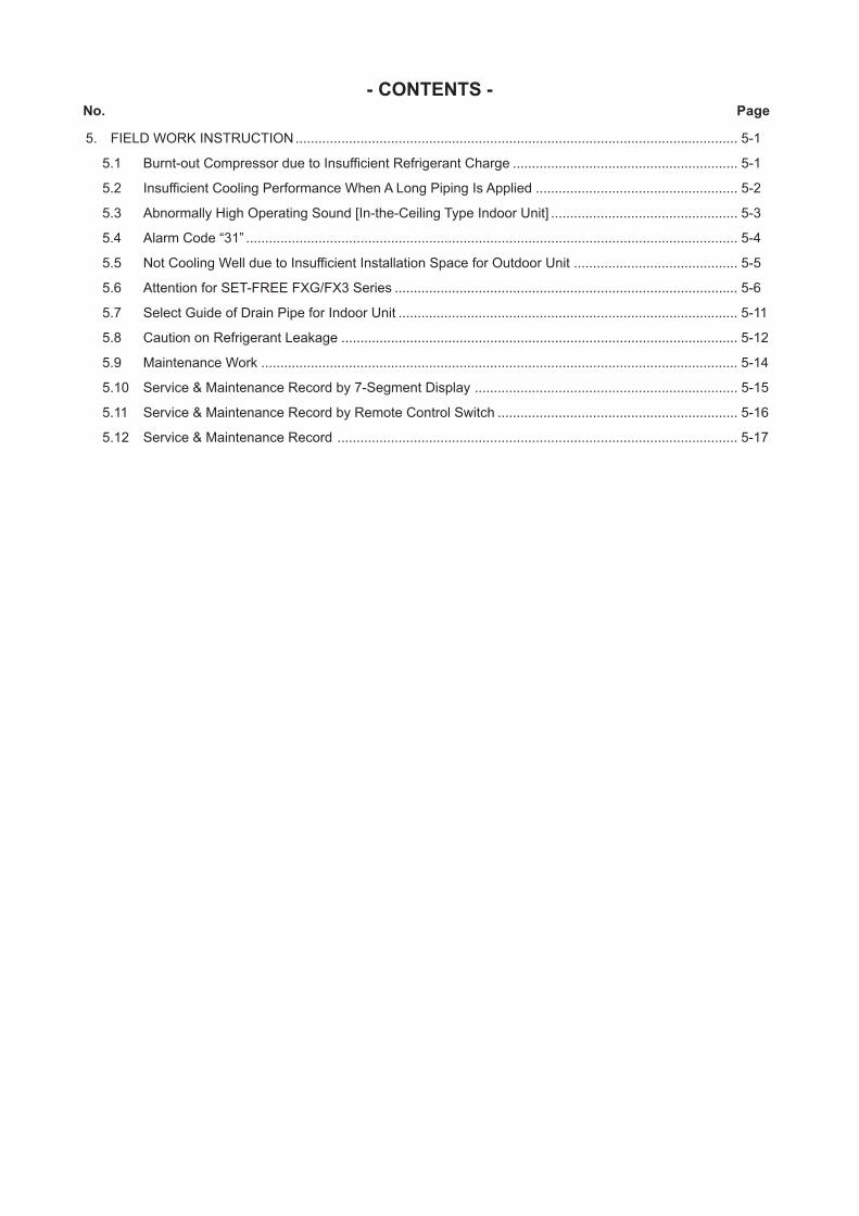
5. FIELD WORK INSTRUCTION.................................................................................................................... 5-1
5.1 Burnt-out Compressor due to Insufficient Refrigerant Charge ........................................................... 5-1
5.2 Insufficient Cooling Performance When A Long Piping Is Applied ..................................................... 5-2
5.3 Abnormally High Operating Sound [In-the-Ceiling Type Indoor Unit] ................................................. 5-3
5.4 Alarm Code “31” ................................................................................................................................. 5-4
5.5 Not Cooling Well due to Insufficient Installation Space for Outdoor Unit ........................................... 5-5
5.6 Attention for SET-FREE FXG/FX3 Series .......................................................................................... 5-6
5.7 Select Guide of Drain Pipe for Indoor Unit ......................................................................................... 5-11
5.8 Caution on Refrigerant Leakage ........................................................................................................ 5-12
5.9 Maintenance Work ............................................................................................................................. 5-14
5.10 Service & Maintenance Record by 7-Segment Display ..................................................................... 5-15
5.11 Service & Maintenance Record by Remote Control Switch ............................................................... 5-16
5.12 Service & Maintenance Record ......................................................................................................... 5-17
- CONTENTS -No. Page
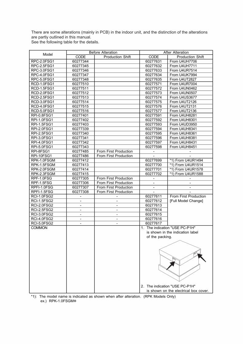
There are some alterations (mainly in PCB) in the indoor unit, and the distinction of the alterations
are partly outlined in this manual.
See the following table for the details.
Before Alteration After Alteration
CODE Production Shift CODE Production Shift
RPC-2.0FSG1 60277344 60277631 From U4UH7706
RPC-2.5FSG1 60277345 60277632 From U4UH7711
RPC-3.0FSG1 60277346 60277633 From U4UR7514
RPC-4.0FSG1 60277347 60277634 From U4UK7994
RPC-5.0FSG1 60277348 60277635 From U4UT2827
RCD-1.0FSG1 60277510 60277571 From U4UR7004
RCD-1.5FSG1 60277511 60277572 From U4UN0462
RCD-2.0FSG1 60277512 60277573 From U4UN0507
RCD-2.5FSG1 60277513 60277574 From U4US3677
RCD-3.0FSG1 60277514 60277575 From U4UT2126
RCD-4.0FSG1 60277515 60277576 From U4UT2131
RCD-5.0FSG1 60277516 60277577 From U4UT2136
RPI-0.8FSG1 60277401 60277591 From U4UH8281
RPI-1.0FSG1 60277402 60277592 From U4UH8301
RPI-1.5FSG1 60277403 60277593 From U4UD3950
RPI-2.0FSG1 60277339 60277594 From U4UH8341
RPI-2.5FSG1 60277340 60277595 From U4UH8361
RPI-3.0FSG1 60277341 60277596 From U4UH8381
RPI-4.0FSG1 60277342 60277597 From U4UH8431
RPI-5.0FSG1 60277343 60277598 From U4UH8451
RPI-8FSG1 60277485 From First Production - -
RPI-10FSG1 60277486 From First Production - -
RPK-1.0FSGM 60277412 60277699 *1) From U4UR1494
RPK-1.5FSGM 60277413 60277700 *1) From U4UR1514
RPK-2.0FSGM 60277414 60277701 *1) From U4UR1578
RPK-2.3FSGM 60277415 60277702 *1) From U4UR1588
RPF-1.0FSG 60277305 From First Production - -
RPF-1.5FSG 60277306 From First Production - -
RPFI-1.0FSG 60277307 From First Production - -
RPFI-1.5FSG 60277308 From First Production - -
RCI-1.0FSG2 - - 60277611 From First Production
RCI-1.5FSG2 - - 60277612 [Full Model Change]
RCI-2.0FSG2 - - 60277613
RCI-2.5FSG2 - - 60277614
RCI-3.0FSG2 - - 60277615
RCI-4.0FSG2 - - 60277616
RCI-5.0FSG2 - - 60277617
COMMON 1. The indication "USE PC-P1H"
is shown in the indication label
of the packing.
2. The indication "USE PC-P1H"
is shown on the electrical box cover.
*1): The model name is indicated as shown when after alteration. (RPK Models Only)
ex.) RPK-1.0FSGM
Model
RCI
1-1
TROUBLESHOOTING
1. TROUBLESHOOTING
1.1 Initial Troubleshooting
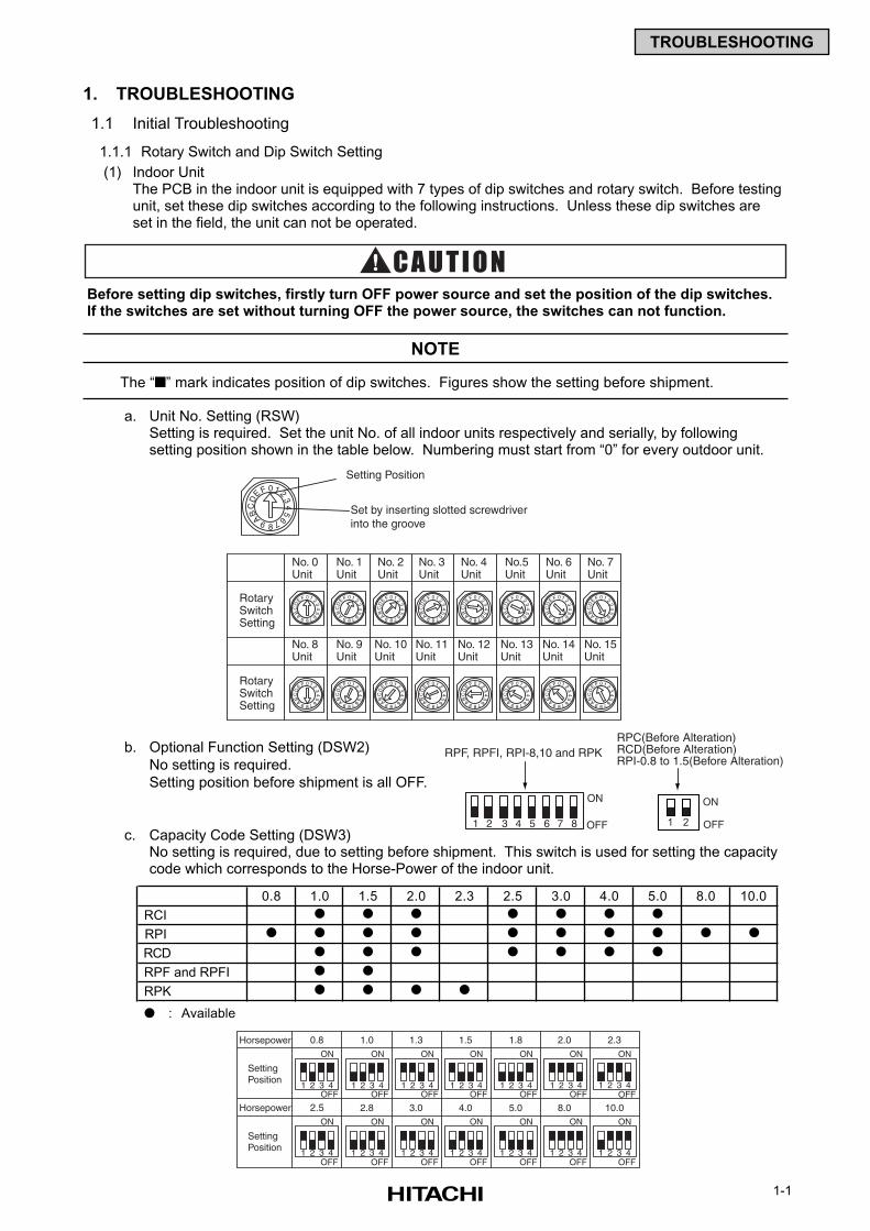
1.1.1 Rotary Switch and Dip Switch Setting
(1) Indoor UnitThe PCB in the indoor unit is equipped with 7 types of dip switches and rotary switch. Before testingunit, set these dip switches according to the following instructions. Unless these dip switches areset in the field, the unit can not be operated.
Before setting dip switches, firstly turn OFF power source and set the position of the dip switches.If the switches are set without turning OFF the power source, the switches can not function.
The “” mark indicates position of dip switches. Figures show the setting before shipment.
a. Unit No. Setting (RSW)Setting is required. Set the unit No. of all indoor units respectively and serially, by followingsetting position shown in the table below. Numbering must start from “0” for every outdoor unit.
b. Optional Function Setting (DSW2)
No setting is required.
Setting position before shipment is all OFF.
01 2
34
5
67
8
9ABC
E F
D
RotarySwitchSetting
RotarySwitchSetting
No. 0Unit
No. 1Unit
No. 2Unit
No. 3Unit
No. 4Unit
No.5Unit
No. 6Unit
No. 7Unit
No. 8Unit
No. 9Unit
No. 10Unit
No. 11Unit
No. 12Unit
No. 13Unit
No. 14Unit
No. 15Unit
Setting Position
Set by inserting slotted screwdriver into the groove
01 2
34
5
67
8
9ABC
E F
D
01 2
34
5
67
8
9ABC
E F
D
01 2
34
5
67
8
9ABC
E F
D
01 2
34
5
67
8
9ABC
E F
D
01 2
34
5
67
8
9ABC
E F
D
01 2
34
5
67
8
9ABC
E F
D
01 2
34
5
67
8
9ABC
E F
D
01 2
34
5
67
8
9ABC
E F
D
01 2
34
5
67
8
9ABC
E F
D
01 2
34
5
67
8
9ABC
E F
D
01 2
34
5
67
8
9ABC
E F
D
01 2
34
5
67
8
9ABC
E F
D
01 2
34
5
67
8
9ABC
E F
D
01 2
34
5
67
8
9ABC
E F
D
01 2
34
5
67
8
9ABC
E F
D
01 2
34
5
67
8
9ABC
E F
D
NOTE
c. Capacity Code Setting (DSW3)No setting is required, due to setting before shipment. This switch is used for setting the capacitycode which corresponds to the Horse-Power of the indoor unit.
1 2 3 4
ON
OFF1 2 3 4
ON
OFF1 2 3 4
ON
OFF1 2 3 4
ON
OFF1 2 3 4
ON
OFF1 2 3 4
ON
OFF1 2 3 4
ON
OFF
1 2 3 4
ON
OFF1 2 3 4
ON
OFF1 2 3 4
ON
OFF1 2 3 4
ON
OFF1 2 3 4
ON
OFF1 2 3 4
ON
OFF1 2 3 4
ON
OFF
SettingPosition
SettingPosition
1.00.8 1.3 1.5 1.8 2.32.0
2.8 3.0 4.0 5.0 8.0 10.02.5
Horsepower
Horsepower
0.8 1.0 1.5 2.0 2.3 2.5 3.0 4.0 5.0 8.0 10.0
RCI
RPI
RCD
RPF and RPFI
RPK
: Available
1 2
ON
OFF
RPC(Before Alteration)RCD(Before Alteration)RPI-0.8 to 1.5(Before Alteration)
1 2 3 4 5 6 7 8
ON
OFF
RPF, RPFI, RPI-8,10 and RPK
1-2
TROUBLESHOOTING
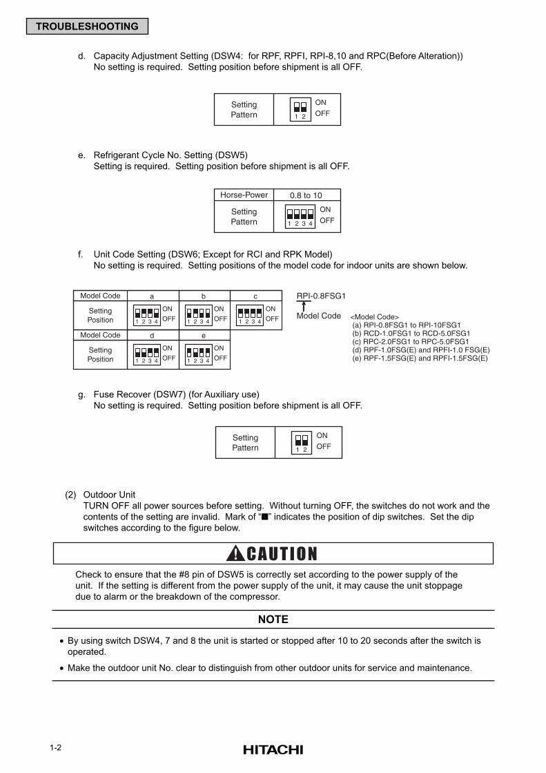
d. Capacity Adjustment Setting (DSW4: for RPF, RPFI, RPI-8,10 and RPC(Before Alteration))
No setting is required. Setting position before shipment is all OFF.
e. Refrigerant Cycle No. Setting (DSW5)
Setting is required. Setting position before shipment is all OFF.
f. Unit Code Setting (DSW6; Except for RCI and RPK Model)
No setting is required. Setting positions of the model code for indoor units are shown below.
g. Fuse Recover (DSW7) (for Auxiliary use)
No setting is required. Setting position before shipment is all OFF.
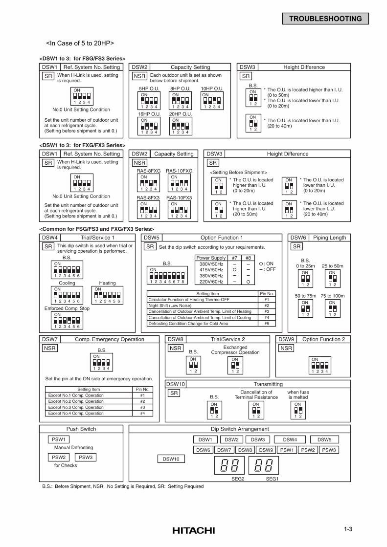
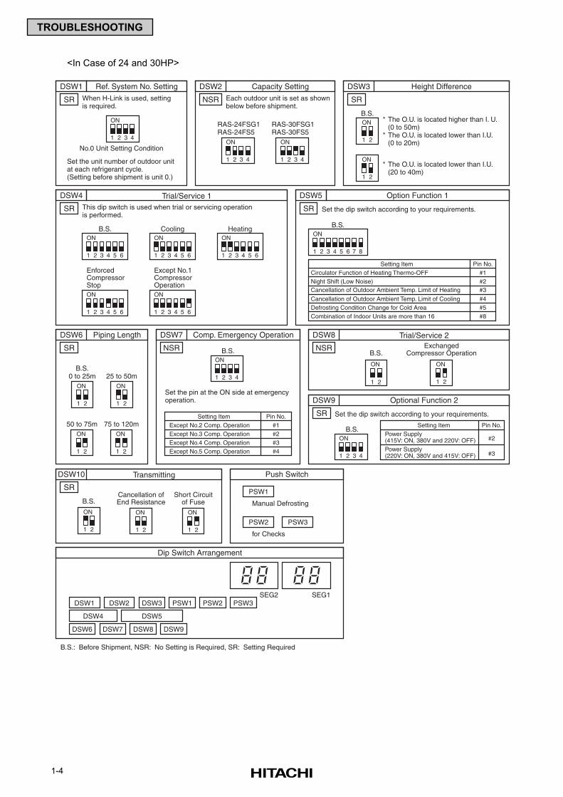
(2) Outdoor Unit
TURN OFF all power sources before setting. Without turning OFF, the switches do not work and the
contents of the setting are invalid. Mark of “” indicates the position of dip switches. Set the dip
switches according to the figure below.
Check to ensure that the #8 pin of DSW5 is correctly set according to the power supply of the
unit. If the setting is different from the power supply of the unit, it may cause the unit stoppage
due to alarm or the breakdown of the compressor.
• By using switch DSW4, 7 and 8 the unit is started or stopped after 10 to 20 seconds after the switch is
operated.
• Make the outdoor unit No. clear to distinguish from other outdoor units for service and maintenance.
NOTE
1 2
ON
OFFSettingPattern
1 2 3 4
ON
OFF
0.8 to 10Horse-Power
SettingPattern
1 2 3 4
ON
OFF1 2 3 4
ON
OFF
d
1 2 3 4
ON
OFF
e
1 2 3 4
ON
OFF
aModel Code RPI-0.8FSG1
Model Code <Model Code> (a) RPI-0.8FSG1 to RPI-10FSG1 (b) RCD-1.0FSG1 to RCD-5.0FSG1 (c) RPC-2.0FSG1 to RPC-5.0FSG1 (d) RPF-1.0FSG(E) and RPFI-1.0 FSG(E) (e) RPF-1.5FSG(E) and RPFI-1.5FSG(E)
SettingPosition 1 2 3 4
ON
OFF
Model Code
SettingPosition
b c
1 2
ON
OFFSettingPattern
1-3
TROUBLESHOOTING
1 2 3 4
ON
1 2 3 4 5 6
ON
DSW1 Ref. System No. Setting
<DSW1 to 3: for FSG/FS3 Series>
When H-Link is used, settingis required.
No.0 Unit Setting Condition
Set the unit number of outdoor unitat each refrigerant cycle.(Setting before shipment is unit 0.)
SR
1 2 3 4
ON
DSW1 Ref. System No. Setting
<DSW1 to 3: for FXG/FX3 Series>
When H-Link is used, settingis required.
No.0 Unit Setting Condition
Set the unit number of outdoor unitat each refrigerant cycle.(Setting before shipment is unit 0.)
SR
DSW4 Trial/Service 1
<Common for FSG/FS3 and FXG/FX3 Series>
This dip switch is used when trial orservicing operation is performed.
SR
1 2 3 4
ON
DSW2 Capacity Setting
Each outdoor unit is set as shownbelow before shipment.
5HP O.U.
1 2 3 4
ON8HP O.U.
1 2 3 4
ON16HP O.U.
1 2 3 4
ON20HP O.U.
1 2 3 4
ON10HP O.U.
NSR
1 2 3 4
ON
DSW2 Capacity Setting
RAS-8FXG
RAS-8FX3
1 2 3 4
ONRAS-10FXG
1 2 3 4
ON
B.S.
1 2 3 4 5 6
ONCooling
1 2 3 4 5 6
ONHeating
1 2 3 4 5 6
ONEnforced Comp. Stop
1 2 3 4 5 6 7 8
ON
DSW5 Option Function 1
Set the dip switch according to your requirements.SR
SR
B.S. 380V/50Hz
Setting Item Pin No.#1#2#3
#4#5Defrosting Condition Change for Cold Area
Circulator Function of Heating Thermo-OFFNight Shift (Low Noise)Cancellation of Outdoor Ambient Temp. Limit of Heating
Cancellation of Outdoor Ambient Temp. Limit of Cooling
Power Supply #7 #8
1 2 3 4
ONRAS-10FX3
NSR
1 2
ON
DSW3 Height Difference
* The O.U. is located higher than I. U.(0 to 50m)
* The O.U. is located lower than I.U.(0 to 20m)
* The O.U. is located lower than I.U.(20 to 40m)
B.S.
1 2
ON
SR
1 2
ON
DSW3 Height Difference
* The O.U. is locatedhigher than I. U.(0 to 20m)
* The O.U. is locatedhigher than I. U.(20 to 50m)
<Setting Before Shipment>
1 2
ON
1 2
ON * The O.U. is locatedlower than I. U.(0 to 20m)
* The O.U. is locatedlower than I. U.(20 to 40m)1 2
ON
SR
1 2
ON
DSW6 Piping Length
B.S.0 to 25m 25 to 50m
1 2
ON
50 to 75m
1 2
ON
75 to 100m
1 2
ON
SR
415V/50Hz380V/60Hz220V/60Hz
: ON: OFF
1 2 3 4
ON
1 2 3 4
ON
Set the pin at the ON side at emergency operation.
B.S.NSR NSR
1 2
ON
DSW8 Trial/Service 2
B.S.Exchanged
Compressor Operation
1 2
ON
1 2
ON
DSW10 Transmitting
B.S.Cancellation of
Terminal Resistance
1 2
ON
when fuseis melted
1 2
ON
DSW7 Comp. Emergency Operation
B.S.: Before Shipment, NSR: No Setting is Required, SR: Setting Required
NSR
DSW9 Option Function 2
Setting Item Pin No.#1#2
Except No.1 Comp. OperationExcept No.2 Comp. Operation
#3Except No.3 Comp. Operation#4Except No.4 Comp. Operation
Manual Defrosting
for Checks
PSW1
PSW2 PSW3
Push Switch
DSW6
DSW1
DSW10
DSW2 DSW3 DSW4 DSW5
DSW7 DSW8 DSW9 PSW1 PSW2 PSW3
Dip Switch Arrangement
SEG2 SEG1
<In Case of 5 to 20HP>
1-4
TROUBLESHOOTING
<In Case of 24 and 30HP>
1 2 3 4
ON
DSW1 Ref. System No. Setting
When H-Link is used, settingis required.
No.0 Unit Setting Condition
Set the unit number of outdoor unitat each refrigerant cycle.(Setting before shipment is unit 0.)
SR
1 2 3 4
ON
DSW2 Capacity Setting
RAS-24FSG1RAS-24FS5
RAS-30FSG1RAS-30FS5
1 2 3 4
ON
NSR
1 2 3 4 5 6
ON
DSW4
SR
B.S.
1 2 3 4 5 6
ONCooling
1 2 3 4 5 6
ONHeating
1 2 3 4 5 6
ON
EnforcedCompressorStop
1 2 3 4 5 6
ON
Except No.1CompressorOperation
1 2
ON
DSW3 Height Difference
* The O.U. is located higher than I. U.(0 to 50m)
* The O.U. is located lower than I.U.(0 to 20m)
* The O.U. is located lower than I.U.(20 to 40m)
B.S.
1 2
ON
SR
1 2
ON
DSW6 Piping Length
B.S.0 to 25m 25 to 50m
1 2
ON
50 to 75m
1 2
ON
75 to 120m
1 2
ON
SR
SR
SR
1 2 3 4 5 6 7 8
ON
DSW5 Option Function 1
SR
B.S.
Setting Item Pin No.#1#2#3
#4#5Defrosting Condition Change for Cold Area#8Combination of Indoor Units are more than 16
Circulator Function of Heating Thermo-OFFNight Shift (Low Noise)Cancellation of Outdoor Ambient Temp. Limit of Heating
Cancellation of Outdoor Ambient Temp. Limit of Cooling
1 2 3 4
ON
Set the pin at the ON side at emergencyoperation.
B.S.NSR NSR
1 2
ON
DSW8 Trial/Service 2
Trial/Service 1
B.S.Exchanged
Compressor Operation
1 21 2
ON
1 2
ON
DSW10 Transmitting
B.S.Cancellation ofEnd Resistance
1 2
ON
Short Circuitof Fuse
1 2
ON
DSW7 Comp. Emergency Operation
B.S.: Before Shipment, NSR: No Setting is Required, SR: Setting Required
Setting Item Pin No.#1#2
Except No.2 Comp. OperationExcept No.3 Comp. Operation
#3Except No.4 Comp. Operation#4Except No.5 Comp. Operation
Setting Item Pin No.
#2Power Supply(415V: ON, 380V and 220V: OFF)
#3Power Supply(220V: ON, 380V and 415V: OFF)1 2 3 4
ONB.S.
DSW9 Optional Function 2
Manual Defrosting
for Checks
PSW1
PSW2 PSW3
Push Switch
DSW1 DSW2 DSW3 PSW1 PSW2 PSW3
DSW6 DSW7 DSW8 DSW9
DSW4 DSW5
Dip Switch Arrangement
SEG2 SEG1
Each outdoor unit is set as shownbelow before shipment.
This dip switch is used when trial or servicing operationis performed.
Set the dip switch according to your requirements.
Set the dip switch according to your requirements.
1-5
TROUBLESHOOTING
1 2 3 4 5 6
ON
OFF
DSW2
1 2
ON
OFF
DSW5
Factory Setting Position(Dip Switch)
DSW2
PCB2
DSW5
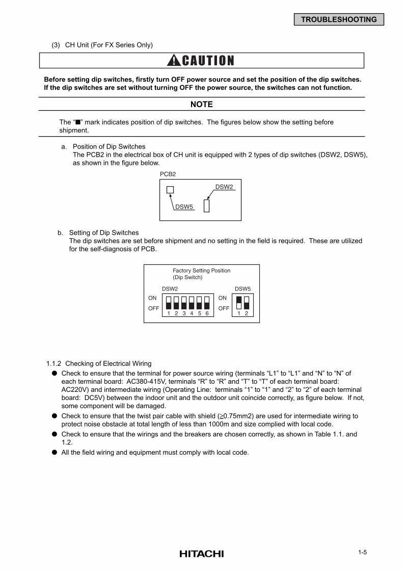
b. Setting of Dip Switches
The dip switches are set before shipment and no setting in the field is required. These are utilized
for the self-diagnosis of PCB.
(3) CH Unit (For FX Series Only)
Before setting dip switches, firstly turn OFF power source and set the position of the dip switches.
If the dip switches are set without turning OFF the power source, the switches can not function.
The “” mark indicates position of dip switches. The figures below show the setting before
shipment.
a. Position of Dip Switches
The PCB2 in the electrical box of CH unit is equipped with 2 types of dip switches (DSW2, DSW5),
as shown in the figure below.
NOTE
1.1.2 Checking of Electrical Wiring
Check to ensure that the terminal for power source wiring (terminals “L1” to “L1” and “N” to “N” of
each terminal board: AC380-415V, terminals “R” to “R” and “T” to “T” of each terminal board:
AC220V) and intermediate wiring (Operating Line: terminals “1” to “1” and “2” to “2” of each terminal
board: DC5V) between the indoor unit and the outdoor unit coincide correctly, as figure below. If not,
some component will be damaged.
Check to ensure that the twist pair cable with shield (≥0.75mm2) are used for intermediate wiring to
protect noise obstacle at total length of less than 1000m and size complied with local code.
Check to ensure that the wirings and the breakers are chosen correctly, as shown in Table 1.1. and
1.2.
All the field wiring and equipment must comply with local code.
1-6
TROUBLESHOOTING
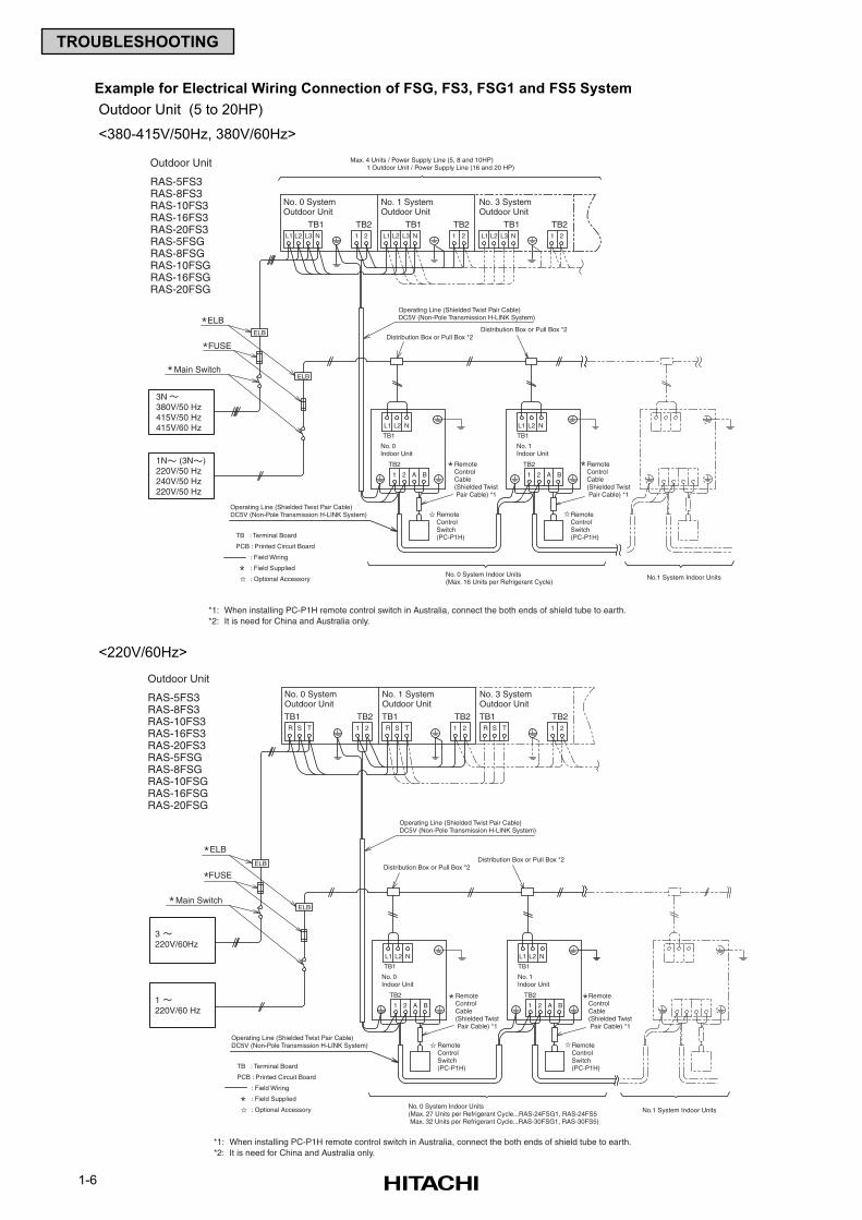
Example for Electrical Wiring Connection of FSG, FS3, FSG1 and FS5 System
Outdoor Unit (5 to 20HP)
<380-415V/50Hz, 380V/60Hz>
No. 0 System Indoor Units(Max. 16 Units per Refrigerant Cycle)
RemoteControlCable(Shielded Twist Pair Cable) *1
RemoteControlCable(Shielded Twist Pair Cable) *1
Remote Control Switch(PC-P1H)
Remote Control Switch(PC-P1H)
No.1 System Indoor Units
Max. 4 Units / Power Supply Line (5, 8 and 10HP) 1 Outdoor Unit / Power Supply Line (16 and 20 HP)
TB1
Outdoor Unit
RAS-5FS3RAS-8FS3RAS-10FS3RAS-16FS3RAS-20FS3RAS-5FSGRAS-8FSGRAS-10FSGRAS-16FSGRAS-20FSG
ELB
FUSE
Main Switch
3N380V/50 Hz415V/50 Hz415V/60 Hz
1N (3N )220V/50 Hz240V/50 Hz220V/50 Hz
ELB
ELB
No. 0 SystemOutdoor Unit
TB1 TB2L1 L2 L3 N 1 2
No. 1 SystemOutdoor Unit
TB1 TB2L1 L2 L3 N 1 2
No. 3 SystemOutdoor Unit
TB1 TB2L1 L2 L3 N 1 2
Operating Line (Shielded Twist Pair Cable)DC5V (Non-Pole Transmission H-LINK System)
*1: When installing PC-P1H remote control switch in Australia, connect the both ends of shield tube to earth.*2: It is need for China and Australia only.
Operating Line (Shielded Twist Pair Cable)DC5V (Non-Pole Transmission H-LINK System)
1 2 A B
TB2
1 2 A B
TB2
TB1
L1 L2 N L1 L2 N
No. 0Indoor Unit
No. 1Indoor Unit
Distribution Box or Pull Box *2Distribution Box or Pull Box *2
TB : Terminal Board
PCB : Printed Circuit Board
: Field Wiring
: Field Supplied
: Optional Accessory
No. 0 System Indoor Units(Max. 27 Units per Refrigerant Cycle...RAS-24FSG1, RAS-24FS5 Max. 32 Units per Refrigerant Cycle...RAS-30FSG1, RAS-30FS5)
RemoteControlCable(Shielded Twist Pair Cable) *1
RemoteControlCable(Shielded Twist Pair Cable) *1
Remote Control Switch(PC-P1H)
Remote Control Switch(PC-P1H)
*1: When installing PC-P1H remote control switch in Australia, connect the both ends of shield tube to earth.*2: It is need for China and Australia only.
No.1 System Indoor Units
Outdoor Unit
RAS-5FS3RAS-8FS3RAS-10FS3RAS-16FS3RAS-20FS3RAS-5FSGRAS-8FSGRAS-10FSGRAS-16FSGRAS-20FSG
TB1
ELB
FUSE
Main Switch
3220V/60Hz
1220V/60 Hz
ELB
ELB
No. 0 SystemOutdoor Unit
TB1 TB2R S T 1 2
No. 1 SystemOutdoor Unit
TB1 TB2R S T 1 2
No. 3 SystemOutdoor Unit
TB1 TB2R S T 1 2
Operating Line (Shielded Twist Pair Cable)DC5V (Non-Pole Transmission H-LINK System)
Operating Line (Shielded Twist Pair Cable)DC5V (Non-Pole Transmission H-LINK System)
1 2 A B
TB2
1 2 A B
TB2
TB1
L1 L2 N L1 L2 N
No. 0Indoor Unit
No. 1Indoor Unit
TB : Terminal Board
PCB : Printed Circuit Board
: Field Wiring
: Field Supplied
: Optional Accessory
Distribution Box or Pull Box *2Distribution Box or Pull Box *2
<220V/60Hz>
1-7
TROUBLESHOOTING
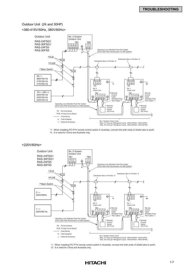
Outdoor Unit (24 and 30HP)
<380-415V/50Hz, 380V/60Hz>
No. 0 System Indoor Units(Max. 27 Units per Refrigerant Cycle...RAS-24FSG1, RAS-24FS5 Max. 32 Units per Refrigerant Cycle...RAS-30FSG1, RAS-30FS5)
RemoteControlCable(Shielded Twist Pair Cable) *1
RemoteControlCable(Shielded Twist Pair Cable) *1
Remote Control Switch(PC-P1H)
Remote Control Switch(PC-P1H)
TB1
Outdoor Unit
RAS-24FSG1RAS-30FSG1RAS-24FS5RAS-30FS5
ELB
FUSE
Main Switch
3N380V/50 Hz415V/50 Hz415V/60 Hz
1N (3N )220V/50 Hz240V/50 Hz220V/50 Hz
ELB
ELB
No. 0 SystemOutdoor Unit
TB1 TB2L1 L2 L3 N 1 2
Operating Line (Shielded Twist Pair Cable)DC5V (Non-Pole Transmission H-LINK System)
*1: When installing PC-P1H remote control switch in Australia, connect the both ends of shield tube to earth.*2: It is need for China and Australia only.
Operating Line (Shielded Twist Pair Cable)DC5V (Non-Pole Transmission H-LINK System)
1 2 A B
TB2
1 2 A B
TB2
TB1
L1 L2 N L1 L2 N
No. 0Indoor Unit
No. 1Indoor Unit
Distribution Box or Pull Box *2Distribution Box or Pull Box *2
TB : Terminal Board
PCB : Printed Circuit Board
: Field Wiring
: Field Supplied
: Optional Accessory
No. 0 System Indoor Units(Max. 27 Units per Refrigerant Cycle...RAS-24FSG1, RAS-24FS5 Max. 32 Units per Refrigerant Cycle...RAS-30FSG1, RAS-30FS5)
RemoteControlCable(Shielded Twist Pair Cable) *1
RemoteControlCable(Shielded Twist Pair Cable) *1
Remote Control Switch(PC-P1H)
Remote Control Switch(PC-P1H)
*1: When installing PC-P1H remote control switch in Australia, connect the both ends of shield tube to earth.*2: It is need for China and Australia only.
TB1
Outdoor Unit
RAS-24FSG1RAS-30FSG1RAS-24FS5RAS-30FS5
ELB
FUSE
Main Switch
3220V/60Hz
1220V/60 Hz
ELB
ELB
No. 0 SystemOutdoor Unit
TB1 TB2R S T 1 2
Operating Line (Shielded Twist Pair Cable)DC5V (Non-Pole Transmission H-LINK System)
Operating Line (Shielded Twist Pair Cable)DC5V (Non-Pole Transmission H-LINK System)
1 2 A B
TB2
1 2 A B
TB2
TB1
L1 L2 N L1 L2 N
No. 0Indoor Unit
No. 1Indoor Unit
TB : Terminal Board
PCB : Printed Circuit Board
: Field Wiring
: Field Supplied
: Optional Accessory
Distribution Box or Pull Box *2Distribution Box or Pull Box *2
<220V/60Hz>
1-8
TROUBLESHOOTING
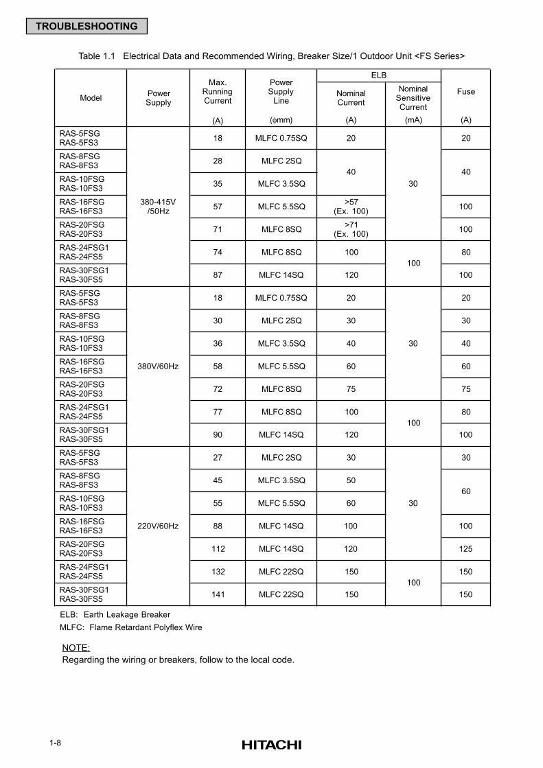
Table 1.1 Electrical Data and Recommended Wiring, Breaker Size/1 Outdoor Unit <FS Series>
NOTE:
Regarding the wiring or breakers, follow to the local code.
NominalCurrent
NominalSensitiveCurrent
(A) (φmm) (A) (mA) (A)
RAS-5FSG RAS-5FS3
18 MLFC 0.75SQ 20 20
RAS-8FSG RAS-8FS3
28 MLFC 2SQ
RAS-10FSG RAS-10FS3
35 MLFC 3.5SQ
RAS-16FSG RAS-16FS3
57 MLFC 5.5SQ>57
(Ex. 100)100
RAS-20FSG RAS-20FS3
71 MLFC 8SQ>71
(Ex. 100)100
RAS-24FSG1 RAS-24FS5
74 MLFC 8SQ 100 80
RAS-30FSG1 RAS-30FS5
87 MLFC 14SQ 120 100
RAS-5FSG RAS-5FS3
18 MLFC 0.75SQ 20 20
RAS-8FSG RAS-8FS3
30 MLFC 2SQ 30 30
RAS-10FSG RAS-10FS3
36 MLFC 3.5SQ 40 40
RAS-16FSG RAS-16FS3
58 MLFC 5.5SQ 60 60
RAS-20FSG RAS-20FS3
72 MLFC 8SQ 75 75
RAS-24FSG1 RAS-24FS5
77 MLFC 8SQ 100 80
RAS-30FSG1 RAS-30FS5
90 MLFC 14SQ 120 100
RAS-5FSG RAS-5FS3
27 MLFC 2SQ 30 30
RAS-8FSG RAS-8FS3
45 MLFC 3.5SQ 50
RAS-10FSG RAS-10FS3
55 MLFC 5.5SQ 60
RAS-16FSG RAS-16FS3
88 MLFC 14SQ 100 100
RAS-20FSG RAS-20FS3
112 MLFC 14SQ 120 125
RAS-24FSG1 RAS-24FS5
132 MLFC 22SQ 150 150
RAS-30FSG1 RAS-30FS5
141 MLFC 22SQ 150 150
ELB: Earth Leakage Breaker
MLFC: Flame Retardant Polyflex Wire
60
100
40
30
40
380-415V/50Hz
ModelPowerSupply
ELB
FusePowerSupply
Line
Max.RunningCurrent
30
220V/60Hz
30
100
100
380V/60Hz
1-9
TROUBLESHOOTING
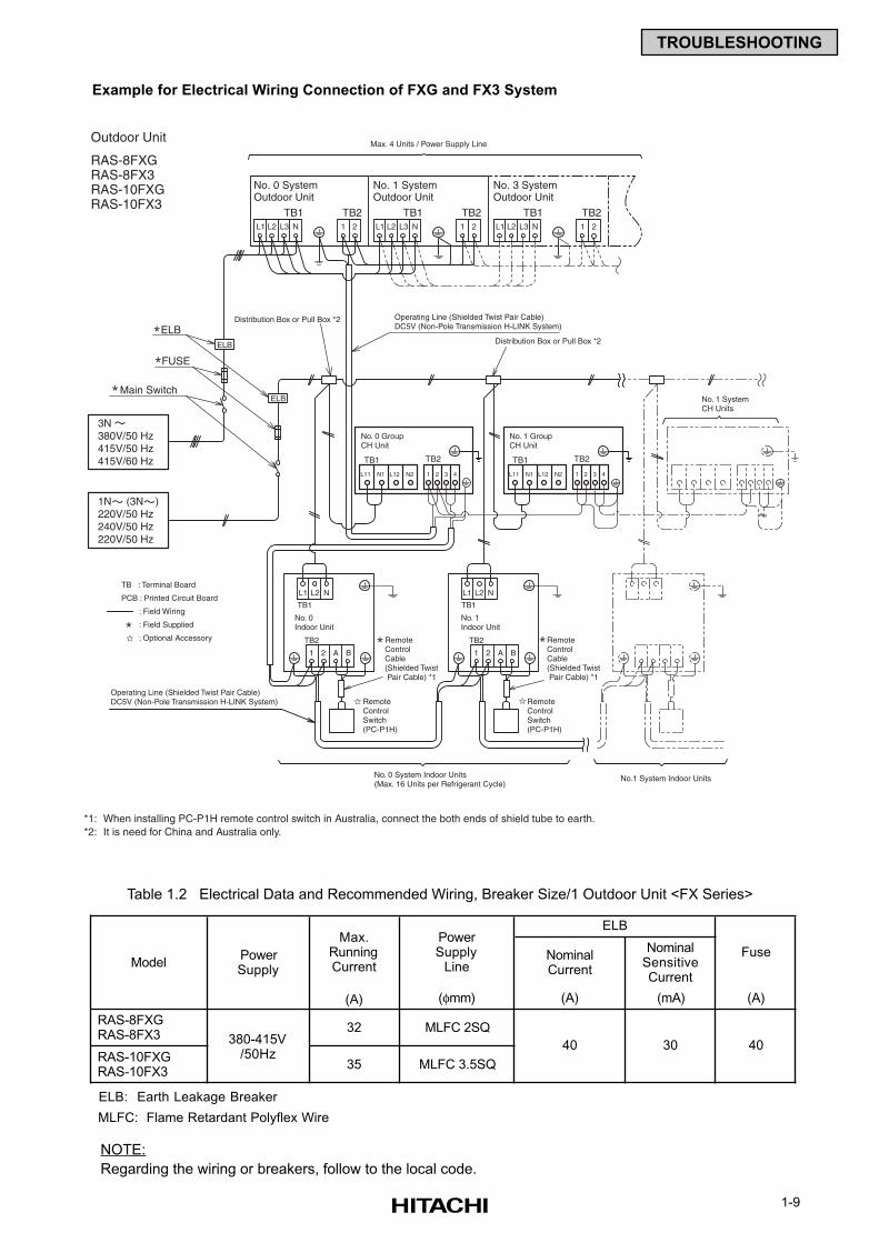
Example for Electrical Wiring Connection of FXG and FX3 System
Table 1.2 Electrical Data and Recommended Wiring, Breaker Size/1 Outdoor Unit <FX Series>
NOTE:
Regarding the wiring or breakers, follow to the local code.
NominalCurrent
NominalSensitiveCurrent
(A) (φmm) (A) (mA) (A)
RAS-8FXG RAS-8FX3
32 MLFC 2SQ
RAS-10FXG RAS-10FX3
35 MLFC 3.5SQ
ELB: Earth Leakage Breaker
MLFC: Flame Retardant Polyflex Wire
380-415V/50Hz
40 30 40
ModelPowerSupply
ELB
FusePowerSupply
Line
Max.RunningCurrent
No. 0 System Indoor Units(Max. 16 Units per Refrigerant Cycle)
RemoteControlCable(Shielded Twist Pair Cable) *1
RemoteControlCable(Shielded Twist Pair Cable) *1
Remote Control Switch(PC-P1H)
Remote Control Switch(PC-P1H)
No.1 System Indoor Units
Max. 4 Units / Power Supply Line
No. 0 GroupCH Unit
No. 1 GroupCH Unit
No. 1 SystemCH Units
TB1
Outdoor Unit
RAS-8FXGRAS-8FX3RAS-10FXGRAS-10FX3
ELB
FUSE
Main Switch
3N380V/50 Hz415V/50 Hz415V/60 Hz
1N (3N )220V/50 Hz240V/50 Hz220V/50 Hz
ELB
ELB
No. 0 SystemOutdoor Unit
TB1 TB2L1 L2 L3 N 1 2
No. 1 SystemOutdoor Unit
TB1 TB2L1 L2 L3 N 1 2
No. 3 SystemOutdoor Unit
TB1 TB2L1 L2 L3 N 1 2
Operating Line (Shielded Twist Pair Cable)DC5V (Non-Pole Transmission H-LINK System)
*1: When installing PC-P1H remote control switch in Australia, connect the both ends of shield tube to earth.*2: It is need for China and Australia only.
Operating Line (Shielded Twist Pair Cable)DC5V (Non-Pole Transmission H-LINK System)
1 2 A B
TB2
1 2 A B
TB2
TB1
L1 L2 N L1 L2 N
No. 0Indoor Unit
No. 1Indoor Unit
Distribution Box or Pull Box *2
Distribution Box or Pull Box *2
TB : Terminal Board
PCB : Printed Circuit Board
: Field Wiring
: Field Supplied
: Optional Accessory
1-10
TROUBLESHOOTING
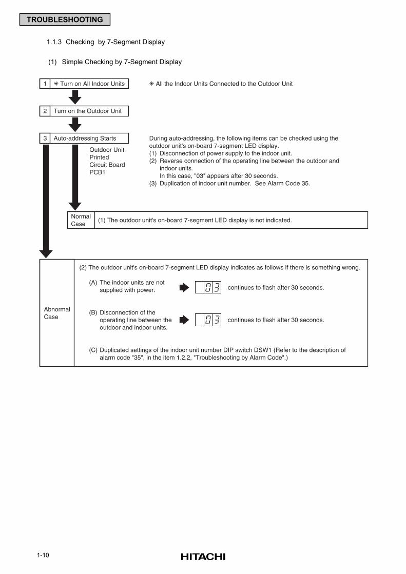
1 Turn on All Indoor Units All the Indoor Units Connected to the Outdoor Unit
During auto-addressing, the following items can be checked using theoutdoor unit's on-board 7-segment LED display.(1) Disconnection of power supply to the indoor unit.(2) Reverse connection of the operating line between the outdoor and
indoor units.In this case, "03" appears after 30 seconds.
(3) Duplication of indoor unit number. See Alarm Code 35.
Outdoor UnitPrintedCircuit BoardPCB1
2 Turn on the Outdoor Unit
3 Auto-addressing Starts
NormalCase
(1) The outdoor unit's on-board 7-segment LED display is not indicated.
continues to flash after 30 seconds.
AbnormalCase
(2) The outdoor unit's on-board 7-segment LED display indicates as follows if there is something wrong.
(A) The indoor units are notsupplied with power.
(B) Disconnection of theoperating line between theoutdoor and indoor units.
(C) Duplicated settings of the indoor unit number DIP switch DSW1 (Refer to the description ofalarm code "35", in the item 1.2.2, "Troubleshooting by Alarm Code".)
continues to flash after 30 seconds.
1.1.3 Checking by 7-Segment Display
(1) Simple Checking by 7-Segment Display
1-11
TROUBLESHOOTING
1.1.4 Emergency Operation when Inverter Compressor is Damaged
(1) Failure of Inverter Compressor
a. Contents of Operation
(Applied Models: RAS-8FSG(3), 10FSG(3), 16FSG(3), 20FSG(3), 24FSG1(5), 30FSG1(5) /
RAS-8FXG(3), 10FXG(3))
* This operation is an emergency operation by a constant compressor, when the inverter
compressor is failed.
* By turning ON “#1” of DSW7 on PCB1 and “#1” of DSW1 on PCB3, emergency operation is
started. (In Case of 5 to 20HP)
* By turning ON “#6” of DSW4 on PCB1 and “#1” of DSW1 on ISPM, emergency operation is
started. (In Case of 24 and 30HP)
* Control of the emergency operation is same with normal control except the inverter compressor
stoppage.
b. Operating Condition
The constant speed compressor is forced to be stopped for compressor protection under the
condition below.
Total Capacity of Thermo-ON indoor units < 50% of Outdoor Unit Capacity
In case of the above condition, the compressor is operated and stopped repeatedly, and it may
cause the compressor failure. Therefore, the compressor is forced to be stopped to protect it.
NOTE:
If the printed circuit board for inverter (PCB3) is damaged, this is not available.
Setting airflow of indoor unit is keeping during enforced stoppage.
Therefore, it is recommended that setting airflow is “Lo” to avoid the person in the room feels cold.
c. Method of Emergency Operation
Checking Before Emergency Operation.
* Measure insulation resistance of the inverter compressor.
Do not perform the emergency operation when the insulation resistance is 0Ω.
There is a possibility that refrigerant oil may be oxidized, if the emergency operation is
performed, the other compressor is damaged.
* In case of total capacity of Thermo-ON indoor units are more than 50% of outdoor unit capacity,
emergency operation is available.
* In this emergency operation, frequency of the compressor is not controlled at each 1Hz.
Therefore, alarm code “07”, “43”, “44”, “45” or “47” may be indicated on LCD. Details of alarm
codes are shown in the alarm code table (page 1-23).
* This emergency operation does not provide sufficient cooling and heating capacity.
* This method is an emergency operation temporarily when the inverter compressor is damaged.
Therefore, change the new one as soon as possible.
* Turn OFF “#1” of DSW7 on PCB1 and “#1” of DSW1 on PCB3 after changing the new
compressor. (In Case of 5 to 20HP)
Turn OFF “#6” of DSW4 on PCB1 and “#1” of DSW1 on ISPM after changing the new
compressor. (In Case of 24 and 30HP)
If this setting is not performed, the inverter compressor will be damaged.
d. Emergency Operation
* Turn OFF all the power source switches.
* Disconnect the wiring from the inverter compressor. Insulate the faston terminals for inverter
compressor wires by insulation tape.
* Set the No.1 of DSW7 on the PCB1 and No.1 of DSW1 on the PCB3 at the “ON” side.
(In Case of 5 to 20HP)
Set “#6” of DSW4 on PCB1 and “#1” of DSW1 on ISPM at the “ON” side.
(In Case of 24 and 30HP)
* Turn ON all the power source switches.
* Operate the system by remote control switches.
* The system is stopped by turning OFF all the remote control switches or turning OFF all the
power source switches.
1-12
TROUBLESHOOTING
(2) Failure of Constant Speed Compressor
a. Contents of Operation
(Applied Models: RAS-8FSG(3), 10FSG(3), 16FSG(3), 20FSG(3), 24FSG1(5), 30FSG1(5) /
RAS-8FXG(3), 10FXG(3))
* This operation is an emergency operation by the inverter compressor, when the constant speed
compressor is failed.
* This operation is controlled by a normal control.
b. Operating Condition
* Set the No.2, 3 or 4 of DSW7 on the PCB1 at the “ON” side. (In case of 5 to 20HP)
* Set the No.1, 2, 3 or 4 of DSW7 on the PCB1 at the “ON” side. (In case of 24 and 30HP)
* Temperature of THM2, THM3 and THM4 on the top of compressors are not ignored by setting
DSW7.
If the thermistor is short-circuited or cut, this operation is available.
1-13
TROUBLESHOOTING
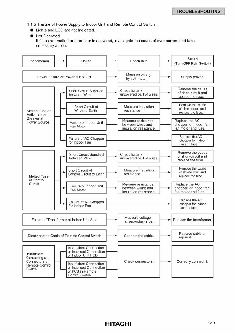
Cause Check ItemAction
(Turn OFF Main Switch)
Measure voltageby volt-meter. Supply power.
Phenomenon
Short Circuit Suppliedbetween Wires
Melted Fuse orActivation ofBreaker atPower Source
Power Failure or Power is Not ON
Check for anyuncovered part of wires.
Remove the causeof short-circuit andreplace the fuse.
Short Circuit ofWires to Earth
Remove the causeof short-circuit andreplace the fuse.
Failure of Indoor UnitFan Motor
Measure resistancebetween wires andinsulation resistance.
Replace the ACchopper for indoor fan,fan motor and fuse.
Failure of AC Chopperfor Indoor Fan
Replace the ACchopper for indoorfan and fuse.
Replace the ACchopper for indoor fan,fan motor and fuse.
Replace the ACchopper for indoorfan and fuse.
Short Circuit Suppliedbetween Wires
Melted Fuseat ControlCircuit
Check for anyuncovered part of wires.
Remove the causeof short-circuit andreplace the fuse.
Short Circuit ofControl Circuit to Earth
Measure insulationresistance.
Measure insulationresistance.
Remove the causeof short-circuit andreplace the fuse.
Failure of Indoor UnitFan Motor
Measure resistancebetween wiring andinsulation resistance.
Failure of AC Chopperfor Indoor Fan
Measure voltageat secondary side. Replace the transformer.Failure of Transformer at Indoor Unit Side
Connect the cable.Replace cable orrepair it.Disconnected Cable of Remote Control Switch
Insufficient Connectionor Incorrect Connectionof Indoor Unit PCBInsufficient
Contacting atConnectors ofRemote ControlSwitch
Check connectors. Correctly connect it.Insufficient Connectionor Incorrect Connectionof PCB in RemoteControl Switch
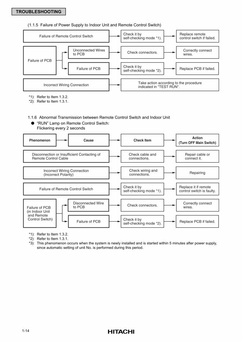
1.1.5 Failure of Power Supply to Indoor Unit and Remote Control Switch
Lights and LCD are not Indicated.
Not Operated
If fuses are melted or a breaker is activated, investigate the cause of over current and take
necessary action.
1-14
TROUBLESHOOTING
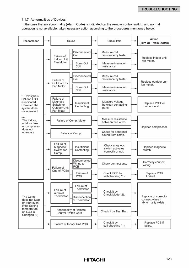
Cause Check ItemAction
(Turn OFF Main Switch)
Check cable andconnections.
Repair cable orconnect it.
Phenomenon
Disconnection or Insufficient Contacting ofRemote Control Cable
Check wiring andconnections. RepairingIncorrect Wiring Connection
(Incorrect Polarity)
Failure of Remote Control Switch Check it byself-checking mode *1).
Check it byself-checking mode *2).
Replace it if remotecontrol switch is faulty.
Check connectors. Correctly connectwires.
Replace PCB if failed.
Disconnected Wireto PCBFailure of PCB
(in Indoor Unit and Remote Control Switch)
Failure of PCB
Failure of Remote Control Switch Check it byself-checking mode *1).
Check it byself-checking mode *2).
Replace remotecontrol switch if failed.
Check connectors. Correctly connectwires.
Replace PCB if failed.
Take action according to the procedureindicated in "TEST RUN".Incorrect Wiring Connection
Unconnected Wiresto PCB
Failure of PCB
Failure of PCB
(1.1.5 Failure of Power Supply to Indoor Unit and Remote Control Switch)
1.1.6 Abnormal Transmission between Remote Control Switch and Indoor Unit
“RUN” Lamp on Remote Control Switch:
Flickering every 2 seconds
*1): Refer to Item 1.3.2.
*2): Refer to Item 1.3.1.
*1): Refer to Item 1.3.2.
*2): Refer to Item 1.3.1.
*3): This phenomenon occurs when the system is newly installed and is started within 5 minutes after power supply,
since automatic setting of unit No. is performed during this period.
1-15
TROUBLESHOOTING
Cause Check ItemAction
(Turn OFF Main Switch)Phenomenon
Measure coilresistance by tester.
Replace indoor unitfan motor.
Failure ofIndoor UnitFan Motor
DisconnectedCoil
"RUN" light isON and LCDis indicated.However, thesystem doesnot operated.
(ex. The indoor, outdoor fans or compressor does not operate.)
The Comp.does not Stopor Start evenif the Settingtemperatureon LCD isChanged *3)
Measure insulationresistance.
Burnt-OutCoil
Measure coilresistance by tester.
Replace outdoor unitfan motor.
Failure ofOutdoor UnitFan Motor
DisconnectedCoil
Measure insulationresistance.
Burnt-OutCoil
Check connections.Failure ofOne of PCBs
DisconnectedWiring toPCB
Check PCB byself-checking *1).
Correctly connectwiring.
Replace PCBif failed.
Check it byself-checking *1).
Check it byCheck Mode *2).
Failure ofPCB
Replace or correctlyconnect wires ifabnormality exists.
Failure ofAir InletThermistor
Failure ofThermistor
Disconnectionof Thermistor
Measure voltagebetween contactingparts.
Replace PCB foroutdoor unit.
Failure ofMagneticSwitch forOutdoor UnitFan Motor
InsufficientContacting
Check magneticswitch activatescorrectly or not.
Replace magneticswitch.
Replace PCB iffailed.
Failure ofMagneticSwitch forComp.
InsufficientContacting
Measure resistancebetween two wires.
Replace compressor.
Failure of Comp. Motor
Check for abnormalsound from comp.Failure of Comp.
Abnormality of RemoteControl Switch Cord Check it by Test Run.
Failure of Indoor Unit PCB
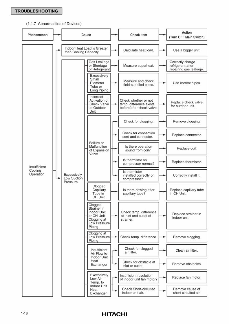
1.1.7 Abnormalities of Devices
In the case that no abnormality (Alarm Code) is indicated on the remote control switch, and normal
operation is not available, take necessary action according to the procedures mentioned below.
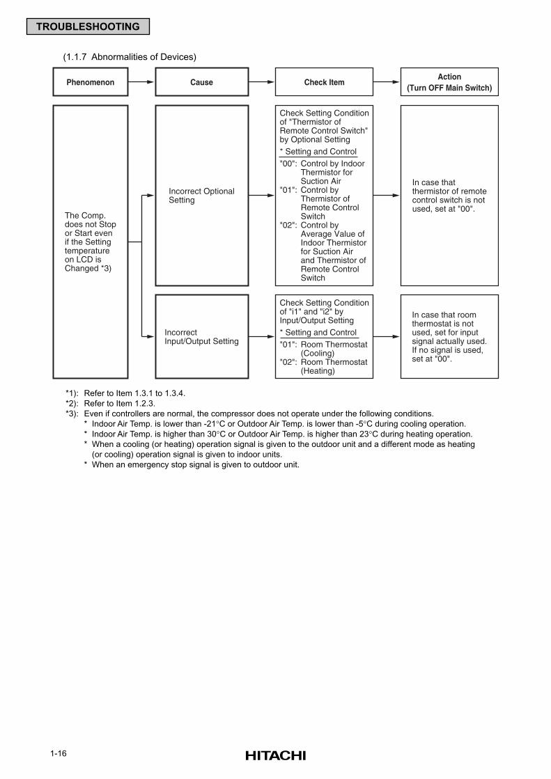
1-16
TROUBLESHOOTING
Incorrect OptionalSetting
The Comp.does not Stopor Start evenif the Settingtemperatureon LCD isChanged *3)
Check Setting Conditionof "Thermistor ofRemote Control Switch"by Optional Setting* Setting and Control"00": Control by Indoor
Thermistor forSuction Air
"01": Control byThermistor ofRemote ControlSwitch
"02": Control byAverage Value ofIndoor Thermistorfor Suction Airand Thermistor ofRemote ControlSwitch
In case thatthermistor of remotecontrol switch is notused, set at "00".
IncorrectInput/Output Setting
Check Setting Conditionof "i1" and "i2" byInput/Output Setting* Setting and Control"01": Room Thermostat
(Cooling)"02": Room Thermostat
(Heating)
In case that roomthermostat is notused, set for inputsignal actually used.If no signal is used,set at "00".
Cause Check ItemAction
(Turn OFF Main Switch)Phenomenon
(1.1.7 Abnormalities of Devices)
*1): Refer to Item 1.3.1 to 1.3.4.
*2): Refer to Item 1.2.3.
*3): Even if controllers are normal, the compressor does not operate under the following conditions.
* Indoor Air Temp. is lower than -21°C or Outdoor Air Temp. is lower than -5°C during cooling operation.
* Indoor Air Temp. is higher than 30°C or Outdoor Air Temp. is higher than 23°C during heating operation.
* When a cooling (or heating) operation signal is given to the outdoor unit and a different mode as heating
(or cooling) operation signal is given to indoor units.
* When an emergency stop signal is given to outdoor unit.
1-17
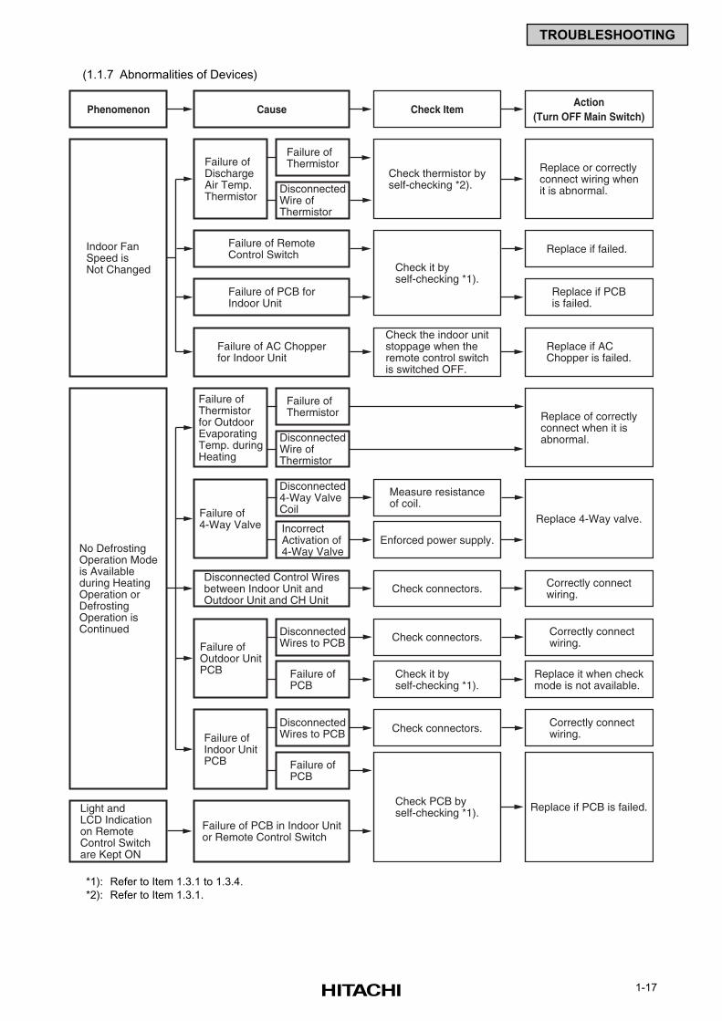
TROUBLESHOOTING
Cause Check ItemAction
(Turn OFF Main Switch)Phenomenon
Check thermistor byself-checking *2).
Replace or correctlyconnect wiring whenit is abnormal.
Check it byself-checking *1).
Check it byself-checking *1).
Check the indoor unitstoppage when theremote control switchis switched OFF.
Failure ofDischargeAir Temp.Thermistor
Failure ofThermistor
Indoor FanSpeed isNot Changed
No DefrostingOperation Modeis Availableduring HeatingOperation orDefrostingOperation isContinued
Light andLCD Indicationon RemoteControl Switchare Kept ON
DisconnectedWire ofThermistor
Failure ofThermistorfor OutdoorEvaporatingTemp. duringHeating
Failure ofThermistor Replace of correctly
connect when it isabnormal.
Replace if failed.
Replace if PCBis failed.
DisconnectedWire ofThermistor
Measure resistanceof coil.
Failure of4-Way Valve
Disconnected4-Way ValveCoil
Enforced power supply.
Replace 4-Way valve.IncorrectActivation of4-Way Valve
Check connectors.Failure ofOutdoor UnitPCB
DisconnectedWires to PCB
Correctly connectwiring.
Replace it when checkmode is not available.
Failure ofPCB
Check PCB byself-checking *1).
Check connectors.Failure ofIndoor UnitPCB
DisconnectedWires to PCB
Correctly connectwiring.
Replace if PCB is failed.
Failure ofPCB
Failure of RemoteControl Switch
Failure of PCB forIndoor Unit
Replace if ACChopper is failed.
Failure of AC Chopperfor Indoor Unit
Check connectors. Correctly connectwiring.
Disconnected Control Wiresbetween Indoor Unit andOutdoor Unit and CH Unit
Failure of PCB in Indoor Unitor Remote Control Switch
(1.1.7 Abnormalities of Devices)
*1): Refer to Item 1.3.1 to 1.3.4.
*2): Refer to Item 1.3.1.
1-18
TROUBLESHOOTING
Cause Check ItemAction
(Turn OFF Main Switch)Phenomenon
Measure superheat.Correctly chargerefrigerant afterrepairing gas leakage.
Measure and checkfield-supplied pipes. Use correct pipes.
ExcessivelyLow SuctionPressure
Gas Leakageor Shortageof Refrigerant
InsufficientCoolingOperation
ExcessivelySmallDiameterTube orLong Piping
Check whether or nottemp. difference existsbefore/after check valve.
Replace check valvefor outdoor unit.
IncorrectActivation ofCheck Valveof OutdoorUnit
Is there dewing aftercapillary tube?
Replace capillary tubein CH Unit.
CloggedCapillaryTube inCH Unit
Check temp. difference. Remove clogging.Clogging atLow PressurePiping
InsufficientAir Flow toIndoor UnitHeatExchanger
Check temp. differenceat inlet and outlet ofstrainer.
Replace strainer inindoor unit.
CloggedStrainer inIndoor Unitor CH UnitClogging atLow PressurePiping
Check for clogging. Remove clogging.
Check for connectioncord and connector. Replace connector.
Check for cloggedair filter. Clean air filter.
Check for obstacle atinlet or outlet. Remove obstacles.
ExcessivelyLow AirTemp. toIndoor UnitHeatExchanger
Insufficient revolutionof indoor unit fan motor? Replace fan motor.
Check Short-circuitedindoor unit air.
Remove cause ofshort-circuited air.
Is there operationsound from coil? Replace coil.
Is thermistor oncompressor normal? Replace thermistor.
Is thermistorinstalled correctly oncompressor?
Correctly install it.
Failure orMalfunctionof ExpansionValve
Calculate heat load. Use a bigger unit.Indoor Heat Load is Greaterthan Cooling Capacity
(1.1.7 Abnormalities of Devices)
1-19
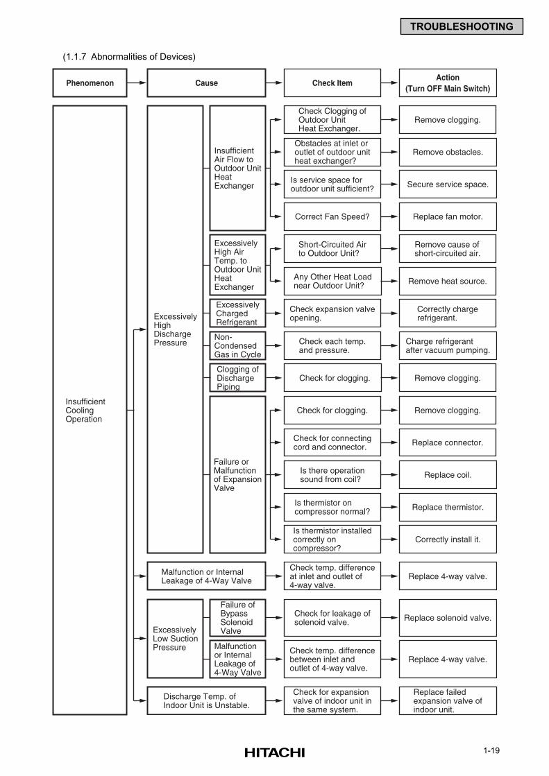
TROUBLESHOOTING
Cause Check ItemAction
(Turn OFF Main Switch)Phenomenon
ExcessivelyHighDischargePressure
InsufficientCoolingOperation
Check expansion valveopening.
Correctly chargerefrigerant.
ExcessivelyChargedRefrigerant
ExcessivelyHigh AirTemp. toOutdoor UnitHeatExchanger
Check each temp.and pressure.
Charge refrigerantafter vacuum pumping.
Non-CondensedGas in Cycle
Check for clogging. Remove clogging.Clogging ofDischargePiping
Check Clogging ofOutdoor UnitHeat Exchanger.
Remove clogging.
Obstacles at inlet oroutlet of outdoor unitheat exchanger?
Remove obstacles.
Short-Circuited Airto Outdoor Unit?
Remove cause ofshort-circuited air.
Any Other Heat Loadnear Outdoor Unit? Remove heat source.
Is service space foroutdoor unit sufficient? Secure service space.
Correct Fan Speed? Replace fan motor.
InsufficientAir Flow toOutdoor UnitHeatExchanger
Check for clogging. Remove clogging.
Check for connectingcord and connector. Replace connector.
Is there operationsound from coil? Replace coil.
Is thermistor oncompressor normal? Replace thermistor.
Is thermistor installedcorrectly oncompressor?
Correctly install it.
Failure orMalfunctionof ExpansionValve
Check temp. differencebetween inlet andoutlet of 4-way valve.
Check for leakage ofsolenoid valve.
ExcessivelyLow SuctionPressure
Failure ofBypassSolenoidValve
Replace solenoid valve.
Replace failedexpansion valve ofindoor unit.
Replace 4-way valve.
Malfunctionor InternalLeakage of4-Way Valve
Check temp. differenceat inlet and outlet of4-way valve.
Replace 4-way valve.Malfunction or InternalLeakage of 4-Way Valve
Check for expansionvalve of indoor unit inthe same system.
Discharge Temp. ofIndoor Unit is Unstable.
(1.1.7 Abnormalities of Devices)
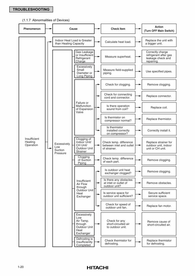
1-20
TROUBLESHOOTING
Cause Check ItemAction
(Turn OFF Main Switch)Phenomenon
ExcessivelyLowSuctionPressure
InsufficientHeatingOperation
Measure superheat.
Correctly chargerefrigerant after gasleakage check andrepairing.
Gas Leakageor InsufficientRefrigerantCharge
Check temp. differenceof each part. Remove clogging.
Cloggingof SuctionPiping
Check temp. differencebetween inlet and outletof strainer.
Replace strainer foroutdoor unit, indoorunit or CH unit.
Clogging ofIndoor Unit/CH Unit/Outdoor UnitStrainer
Check thermistor fordefrosting.
Replace thermistorfor defrosting.
Defrosting isInsufficientlyCompleted
Check for anyshort-circuited airto outdoor unit.
Remove cause ofshort-circuited air.
ExcessivelyLowAir Temp.throughOutdoor UnitHeatExchanger
Measure field-suppliedpiping. Use specified pipes.
ExcessivelySmallDiameter orLong Piping
Is outdoor unit heatexchanger clogged? Remove clogging.
Is there any obstaclesat inlet or outlet ofoutdoor unit?
Remove obstacles.
Is service space foroutdoor unit sufficient?
Secure sufficientservice space.
Check for speed ofoutdoor unit fan. Replace fan motor.
InsufficientAir FlowthroughOutdoor UnitHeatExchanger
Check for clogging. Remove clogging.
Check for connectingcord and connector. Replace connector.
Is there operationsound from coil? Replace coil.
Is thermistor oncompressor normal? Replace thermistor.
Is thermistorinstalled correctlyon compressor?
Correctly install it.
Failure orMalfunctionof ExpansionValve
Calculate heat load. Replace the unit witha bigger unit.
Indoor Heat Load is Greaterthan Heating Capacity
(1.1.7 Abnormalities of Devices)
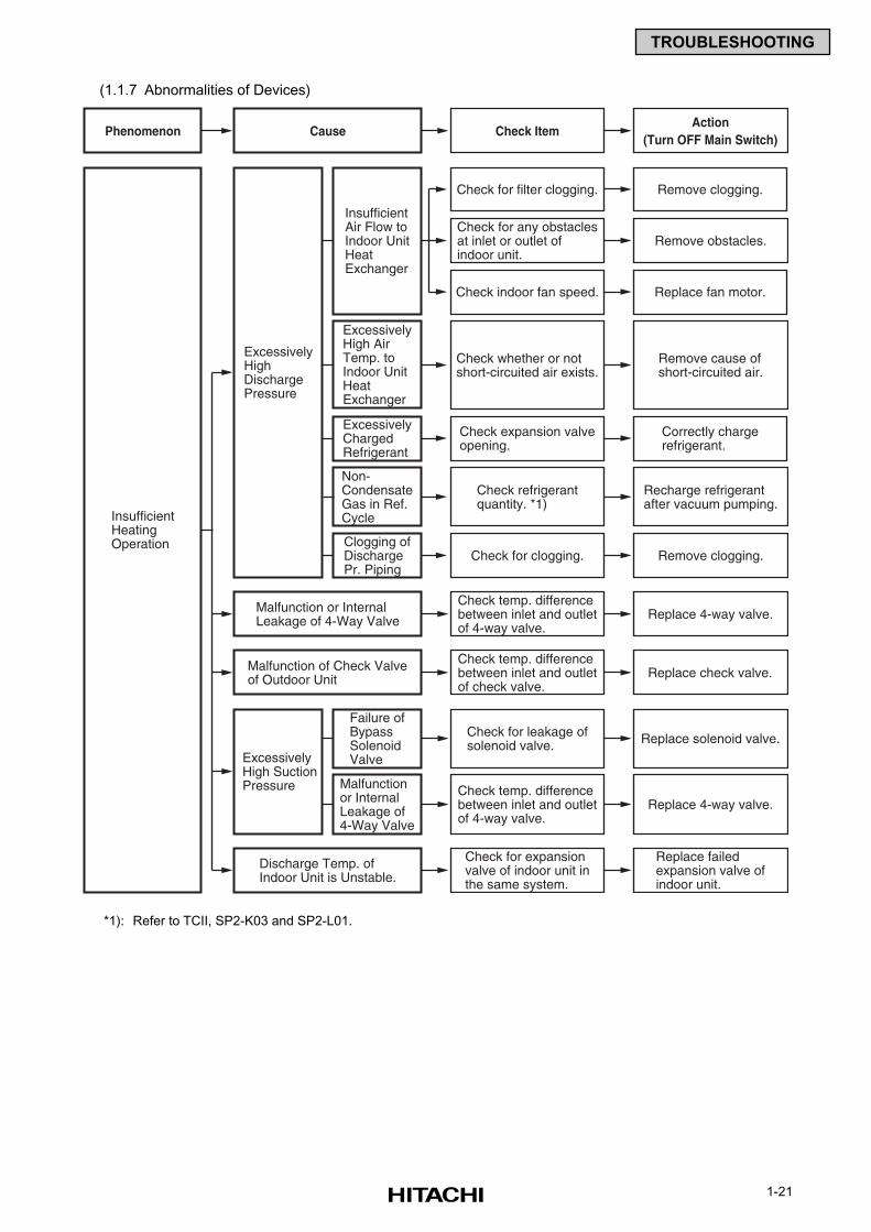
1-21
TROUBLESHOOTING
Cause Check ItemAction
(Turn OFF Main Switch)Phenomenon
ExcessivelyHighDischargePressure
InsufficientHeatingOperation
Check whether or notshort-circuited air exists.
Remove cause ofshort-circuited air.
ExcessivelyHigh AirTemp. toIndoor UnitHeatExchanger
Check expansion valveopening.
Correctly chargerefrigerant.
ExcessivelyChargedRefrigerant
Check for clogging. Remove clogging.Clogging ofDischargePr. Piping
Check refrigerantquantity. *1)
Recharge refrigerantafter vacuum pumping.
Non-CondensateGas in Ref.Cycle
Check for filter clogging. Remove clogging.
Check for any obstaclesat inlet or outlet ofindoor unit.
Remove obstacles.
Check indoor fan speed. Replace fan motor.
InsufficientAir Flow toIndoor UnitHeatExchanger
Check temp. differencebetween inlet and outletof 4-way valve.
Check for leakage ofsolenoid valve.
ExcessivelyHigh SuctionPressure
Failure ofBypassSolenoidValve
Replace solenoid valve.
Replace failedexpansion valve ofindoor unit.
Replace 4-way valve.
Malfunctionor InternalLeakage of4-Way Valve
Check temp. differencebetween inlet and outletof 4-way valve.
Replace 4-way valve.Malfunction or InternalLeakage of 4-Way Valve
Check temp. differencebetween inlet and outletof check valve.
Replace check valve.Malfunction of Check Valveof Outdoor Unit
Check for expansionvalve of indoor unit inthe same system.
Discharge Temp. ofIndoor Unit is Unstable.
(1.1.7 Abnormalities of Devices)
*1): Refer to TCII, SP2-K03 and SP2-L01.
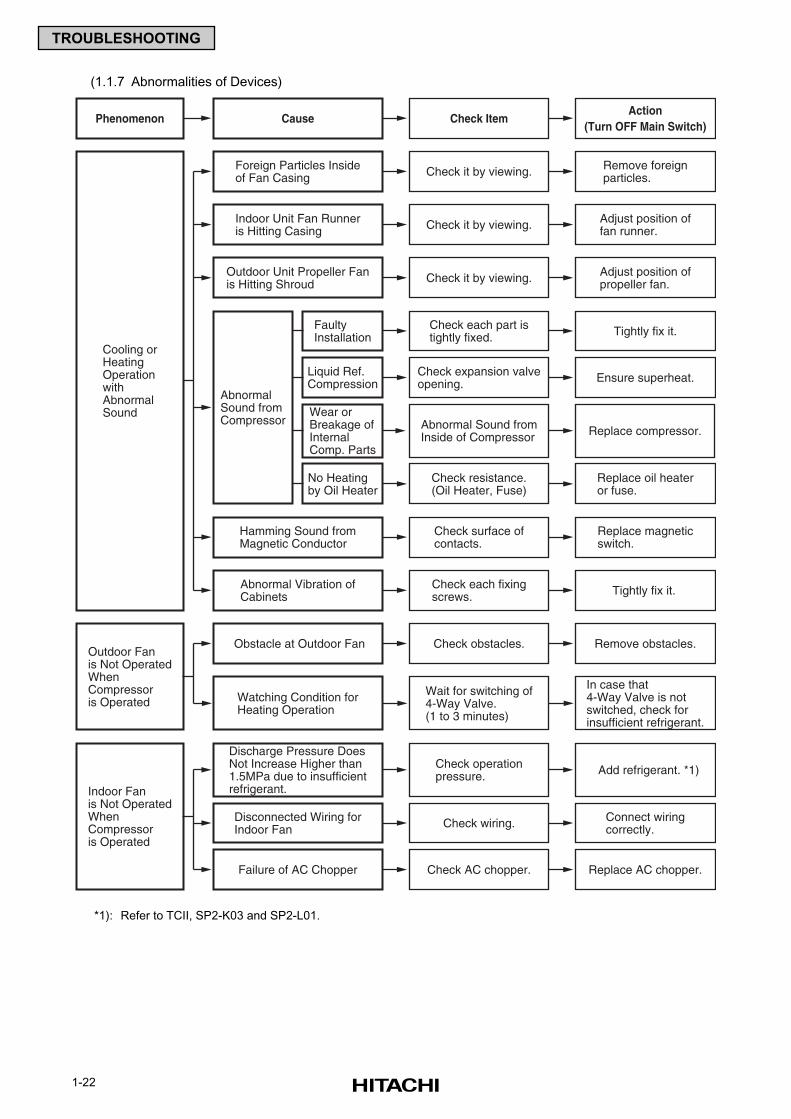
1-22
TROUBLESHOOTING
Cause Check ItemAction
(Turn OFF Main Switch)Phenomenon
Cooling orHeatingOperationwithAbnormalSound
Outdoor Fanis Not OperatedWhenCompressoris Operated
Abnormal Sound fromInside of Compressor Replace compressor.
Wear orBreakage ofInternalComp. Parts
Check expansion valveopening.
Check each part istightly fixed.
AbnormalSound fromCompressor
FaultyInstallation Tightly fix it.
Ensure superheat.Liquid Ref.Compression
Check resistance.(Oil Heater, Fuse)
Replace oil heateror fuse.
No Heatingby Oil Heater
Check it by viewing. Remove foreignparticles.
Foreign Particles Insideof Fan Casing
Check it by viewing. Adjust position offan runner.
Indoor Unit Fan Runneris Hitting Casing
Check it by viewing. Adjust position ofpropeller fan.
Outdoor Unit Propeller Fanis Hitting Shroud
Check surface ofcontacts.
Replace magneticswitch.
Hamming Sound fromMagnetic Conductor
Check each fixingscrews. Tightly fix it.Abnormal Vibration of
Cabinets
Check obstacles. Remove obstacles.Obstacle at Outdoor Fan
Check wiring. Connect wiringcorrectly.
Disconnected Wiring forIndoor Fan
Check AC chopper. Replace AC chopper.Failure of AC Chopper
Wait for switching of4-Way Valve.(1 to 3 minutes)
In case that4-Way Valve is notswitched, check forinsufficient refrigerant.
Watching Condition forHeating Operation
Indoor Fanis Not OperatedWhenCompressoris Operated
Check operationpressure. Add refrigerant. *1)
Discharge Pressure DoesNot Increase Higher than1.5MPa due to insufficientrefrigerant.
(1.1.7 Abnormalities of Devices)
*1): Refer to TCII, SP2-K03 and SP2-L01.
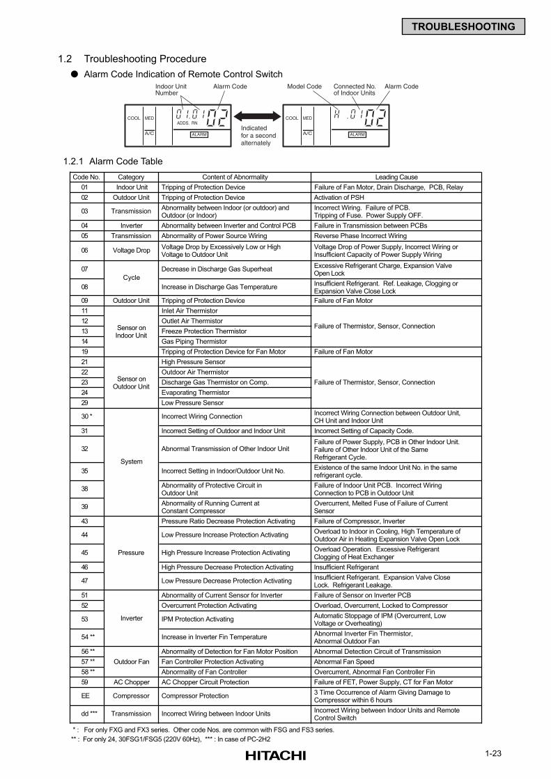
1-23
TROUBLESHOOTING
COOL
Indoor UnitNumber
Alarm Code
Indicatedfor a secondalternately
MED
A/C
ADDS. RN
ALARM
COOL
Connected No.of Indoor Units
Alarm CodeModel Code
MED
A/C ALARM
1.2 Troubleshooting Procedure
Alarm Code Indication of Remote Control Switch
1.2.1 Alarm Code Table
Code No. Category Content of Abnormality Leading Cause
01 Indoor Unit Tripping of Protection Device Failure of Fan Motor, Drain Discharge, PCB, Relay
02 Outdoor Unit Tripping of Protection Device Activation of PSH
03 Transmission Abnormality between Indoor (or outdoor) and Outdoor (or Indoor)
Incorrect Wiring. Failure of PCB. Tripping of Fuse. Power Supply OFF.
04 Inverter Abnormality between Inverter and Control PCB Failure in Transmission between PCBs
05 Transmission Abnormality of Power Source Wiring Reverse Phase Incorrect Wiring
06 Voltage Drop Voltage Drop by Excessively Low or High Voltage to Outdoor Unit
Voltage Drop of Power Supply, Incorrect Wiring or Insufficient Capacity of Power Supply Wiring
07 Decrease in Discharge Gas Superheat Excessive Refrigerant Charge, Expansion Valve Open Lock
08 Increase in Discharge Gas Temperature Insufficient Refrigerant. Ref. Leakage, Clogging or Expansion Valve Close Lock
09 Outdoor Unit Tripping of Protection Device Failure of Fan Motor
11 Inlet Air Thermistor
12 Outlet Air Thermistor
13 Freeze Protection Thermistor
14 Gas Piping Thermistor
19 Tripping of Protection Device for Fan Motor Failure of Fan Motor
21 High Pressure Sensor
22 Outdoor Air Thermistor
23 Discharge Gas Thermistor on Comp.
24 Evaporating Thermistor
29 Low Pressure Sensor
30 * Incorrect Wiring Connection Incorrect Wiring Connection between Outdoor Unit, CH Unit and Indoor Unit
31 Incorrect Setting of Outdoor and Indoor Unit Incorrect Setting of Capacity Code.
32 Abnormal Transmission of Other Indoor Unit Failure of Power Supply, PCB in Other Indoor Unit. Failure of Other Indoor Unit of the Same Refrigerant Cycle.
35 Incorrect Setting in Indoor/Outdoor Unit No. Existence of the same Indoor Unit No. in the same refrigerant cycle.
38 Abnormality of Protective Circuit in Outdoor Unit
Failure of Indoor Unit PCB. Incorrect Wiring Connection to PCB in Outdoor Unit
39 Abnormality of Running Current at Constant Compressor
Overcurrent, Melted Fuse of Failure of Current Sensor
43 Pressure Ratio Decrease Protection Activating Failure of Compressor, Inverter
44 Low Pressure Increase Protection Activating Overload to Indoor in Cooling, High Temperature of Outdoor Air in Heating Expansion Valve Open Lock
45 High Pressure Increase Protection Activating Overload Operation. Excessive Refrigerant Clogging of Heat Exchanger
46 High Pressure Decrease Protection Activating Insufficient Refrigerant
47 Low Pressure Decrease Protection Activating Insufficient Refrigerant. Expansion Valve Close Lock. Refrigerant Leakage.
51 Abnormality of Current Sensor for Inverter Failure of Sensor on Inverter PCB
52 Overcurrent Protection Activating Overload, Overcurrent, Locked to Compressor
53 IPM Protection Activating Automatic Stoppage of IPM (Overcurrent, Low Voltage or Overheating)
54 ** Increase in Inverter Fin Temperature Abnormal Inverter Fin Thermistor, Abnormal Outdoor Fan
56 ** Abnormality of Detection for Fan Motor Position Abnormal Detection Circuit of Transmission
57 ** Fan Controller Protection Activating Abnormal Fan Speed
58 ** Abnormality of Fan Controller Overcurrent, Abnormal Fan Controller Fin
59 AC Chopper AC Chopper Circuit Protection Failure of FET, Power Supply, CT for Fan Motor
EE Compressor Compressor Protection 3 Time Occurrence of Alarm Giving Damage to Compressor within 6 hours
dd *** Transmission Incorrect Wiring between Indoor Units Incorrect Wiring between Indoor Units and Remote Control Switch
* : For only FXG and FX3 series. Other code Nos. are common with FSG and FS3 series.
** : For only 24, 30FSG1/FSG5 (220V 60Hz), *** : In case of PC-2H2
Failure of Thermistor, Sensor, Connection
Cycle
Sensor onIndoor Unit
Sensor onOutdoor Unit
Failure of Thermistor, Sensor, Connection
Outdoor Fan
Inverter
Pressure
System
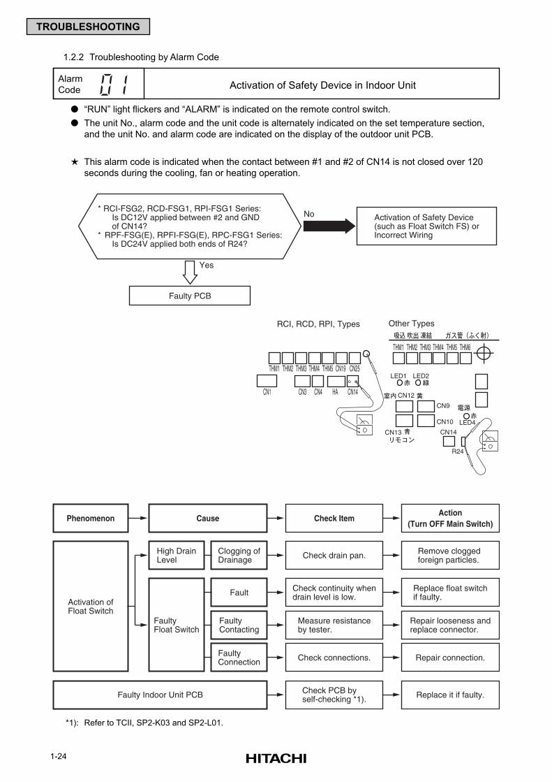
1-24
TROUBLESHOOTING
* RCI-FSG2, RCD-FSG1, RPI-FSG1 Series:Is DC12V applied between #2 and GNDof CN14?
* RPF-FSG(E), RPFI-FSG(E), RPC-FSG1 Series:Is DC24V applied both ends of R24?
Activation of Safety Device(such as Float Switch FS) orIncorrect Wiring
Faulty PCB
Yes
No
Cause Check ItemAction
(Turn OFF Main Switch)Phenomenon
Activation ofFloat Switch
Check continuity whendrain level is low.
Check drain pan.High DrainLevel
FaultyFloat Switch
Clogging ofDrainage
Remove clogged foreign particles.
Replace float switchif faulty.Fault
Measure resistanceby tester.
Repair looseness andreplace connector.
FaultyContacting
Check connections. Repair connection.FaultyConnection
Check PCB byself-checking *1). Replace it if faulty.Faulty Indoor Unit PCB
1.2.2 Troubleshooting by Alarm Code
“RUN” light flickers and “ALARM” is indicated on the remote control switch.
The unit No., alarm code and the unit code is alternately indicated on the set temperature section,
and the unit No. and alarm code are indicated on the display of the outdoor unit PCB.
This alarm code is indicated when the contact between #1 and #2 of CN14 is not closed over 120
seconds during the cooling, fan or heating operation.
*1): Refer to TCII, SP2-K03 and SP2-L01.
Alarm
Code Activation of Safety Device in Indoor Unit
THM1 THM2 THM3 THM4 THM5 CN19 CN25
THM1 THM2 THM3 THM4 THM5 THM6
CN1 CN3 CN4 HA CN14
RCI, RCD, RPI, Types Other Types
LED1 LED2
LED4
CN12
CN9
CN10
CN14CN13
R24
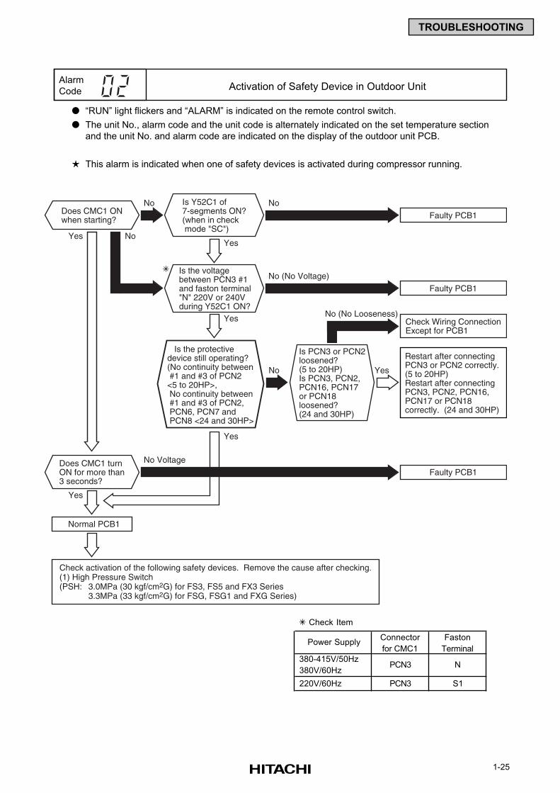
1-25
TROUBLESHOOTING
Does CMC1 ONwhen starting?
Is Y52C1 of7-segments ON?(when in check mode "SC")
Does CMC1 turnON for more than3 seconds?
Faulty PCB1
Yes
No
No
Normal PCB1
Yes
Is the voltagebetween PCN3 #1and faston terminal"N" 220V or 240Vduring Y52C1 ON?
Yes
Is the protectivedevice still operating?(No continuity between #1 and #3 of PCN2<5 to 20HP>, No continuity between #1 and #3 of PCN2, PCN6, PCN7 and PCN8 <24 and 30HP>
Is PCN3 or PCN2loosened?(5 to 20HP)Is PCN3, PCN2,PCN16, PCN17or PCN18 loosened?(24 and 30HP)
Yes
Yes
Yes
Check activation of the following safety devices. Remove the cause after checking.(1) High Pressure Switch(PSH: 3.0MPa (30 kgf/cm2G) for FS3, FS5 and FX3 Series
3.3MPa (33 kgf/cm2G) for FSG, FSG1 and FXG Series)
No
Faulty PCB1
No Voltage
Faulty PCB1
Restart after connectingPCN3 or PCN2 correctly.(5 to 20HP)Restart after connectingPCN3, PCN2, PCN16,PCN17 or PCN18correctly. (24 and 30HP)
Check Wiring ConnectionExcept for PCB1
No (No Voltage)
No (No Looseness)
No
“RUN” light flickers and “ALARM” is indicated on the remote control switch.
The unit No., alarm code and the unit code is alternately indicated on the set temperature section
and the unit No. and alarm code are indicated on the display of the outdoor unit PCB.
This alarm is indicated when one of safety devices is activated during compressor running.
Alarm
Code Activation of Safety Device in Outdoor Unit
Check Item
Connector Faston
for CMC1 Terminal
380-415V/50Hz
380V/60Hz
220V/60Hz PCN3 S1
N
Power Supply
PCN3
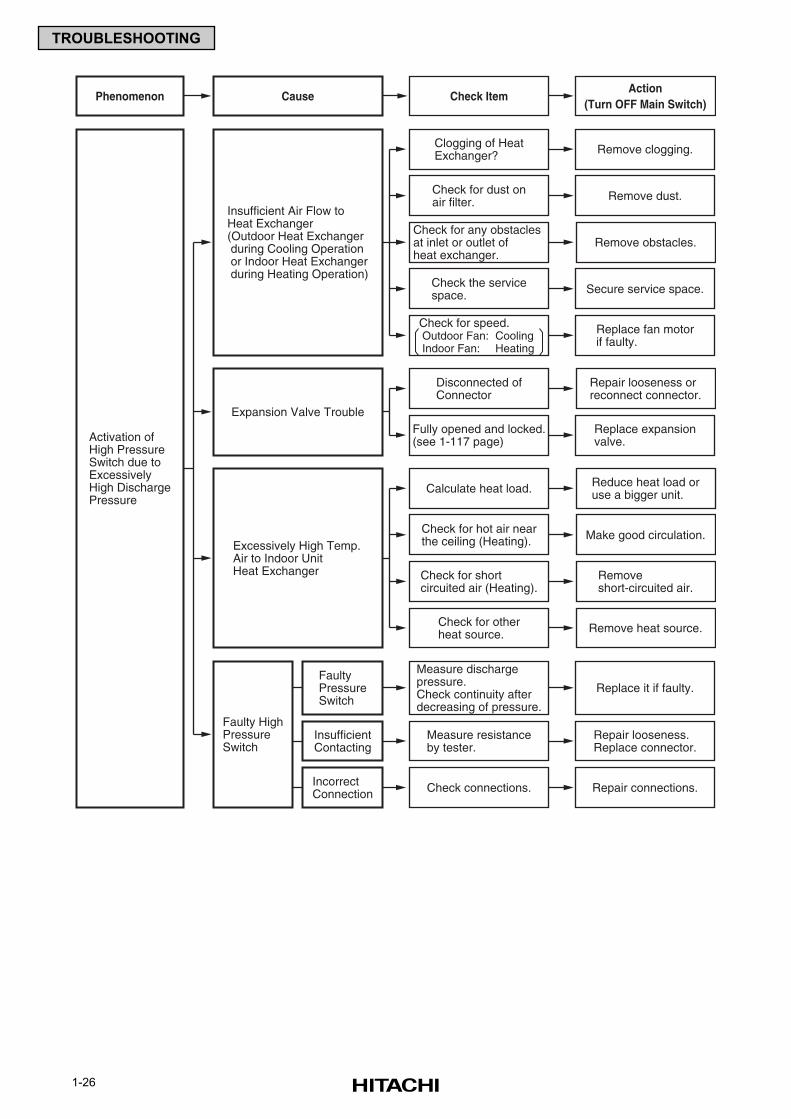
1-26
TROUBLESHOOTING
Cause Check ItemAction
(Turn OFF Main Switch)Phenomenon
Activation ofHigh PressureSwitch due toExcessivelyHigh DischargePressure
Disconnected ofConnector
Repair looseness orreconnect connector.
Fully opened and locked.(see 1-117 page)
Replace expansionvalve.
Expansion Valve Trouble
Measure dischargepressure.Check continuity afterdecreasing of pressure.
Replace it if faulty.FaultyPressureSwitch
Faulty HighPressureSwitch
Measure resistanceby tester.
Repair looseness.Replace connector.
InsufficientContacting
Check connections. Repair connections.IncorrectConnection
Calculate heat load. Reduce heat load oruse a bigger unit.
Check for hot air nearthe ceiling (Heating). Make good circulation.
Check for shortcircuited air (Heating).
Removeshort-circuited air.
Check for otherheat source. Remove heat source.
Excessively High Temp.Air to Indoor UnitHeat Exchanger
Clogging of HeatExchanger? Remove clogging.
Check for dust onair filter. Remove dust.
Check for any obstaclesat inlet or outlet ofheat exchanger.
Remove obstacles.
Check the servicespace. Secure service space.
Check for speed. Outdoor Fan: Cooling Indoor Fan: Heating
Replace fan motorif faulty.
Insufficient Air Flow toHeat Exchanger(Outdoor Heat Exchanger during Cooling Operation or Indoor Heat Exchanger during Heating Operation)
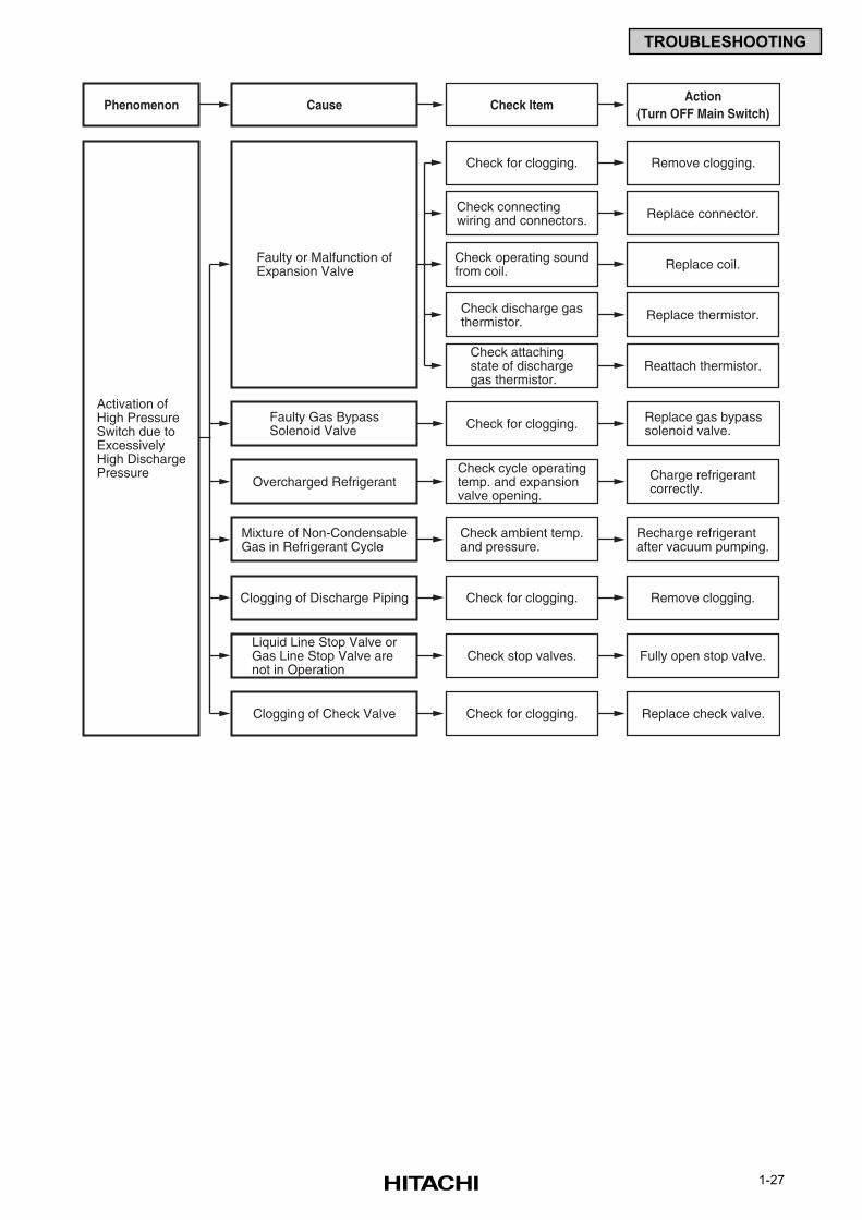
1-27
TROUBLESHOOTING
Cause Check ItemAction
(Turn OFF Main Switch)Phenomenon
Activation ofHigh PressureSwitch due toExcessivelyHigh DischargePressure
Check for clogging. Replace gas bypasssolenoid valve.
Faulty Gas BypassSolenoid Valve
Check for clogging. Remove clogging.
Check connectingwiring and connectors. Replace connector.
Check operating soundfrom coil. Replace coil.
Check discharge gasthermistor.
Check attachingstate of dischargegas thermistor.
Replace thermistor.
Reattach thermistor.
Faulty or Malfunction ofExpansion Valve
Check cycle operatingtemp. and expansionvalve opening.
Charge refrigerantcorrectly.Overcharged Refrigerant
Check ambient temp.and pressure.
Recharge refrigerantafter vacuum pumping.
Mixture of Non-CondensableGas in Refrigerant Cycle
Check for clogging. Remove clogging.Clogging of Discharge Piping
Check stop valves. Fully open stop valve.Liquid Line Stop Valve orGas Line Stop Valve arenot in Operation
Check for clogging. Replace check valve.Clogging of Check Valve
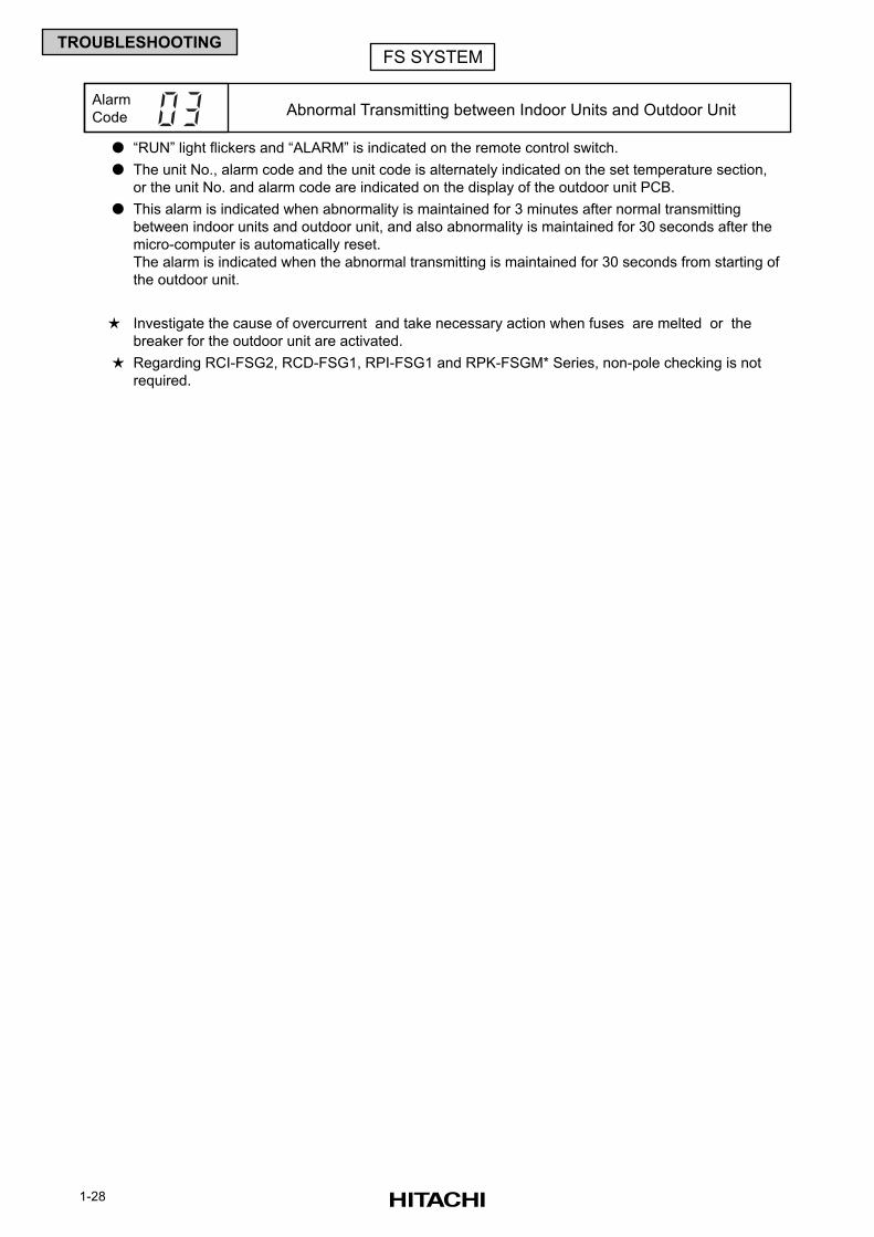
1-28
TROUBLESHOOTING
“RUN” light flickers and “ALARM” is indicated on the remote control switch.
The unit No., alarm code and the unit code is alternately indicated on the set temperature section,
or the unit No. and alarm code are indicated on the display of the outdoor unit PCB.
This alarm is indicated when abnormality is maintained for 3 minutes after normal transmitting
between indoor units and outdoor unit, and also abnormality is maintained for 30 seconds after the
micro-computer is automatically reset.
The alarm is indicated when the abnormal transmitting is maintained for 30 seconds from starting of
the outdoor unit.
Investigate the cause of overcurrent and take necessary action when fuses are melted or the
breaker for the outdoor unit are activated.
Regarding RCI-FSG2, RCD-FSG1, RPI-FSG1 and RPK-FSGM* Series, non-pole checking is not
required.
Alarm
Code Abnormal Transmitting between Indoor Units and Outdoor Unit
FS SYSTEM
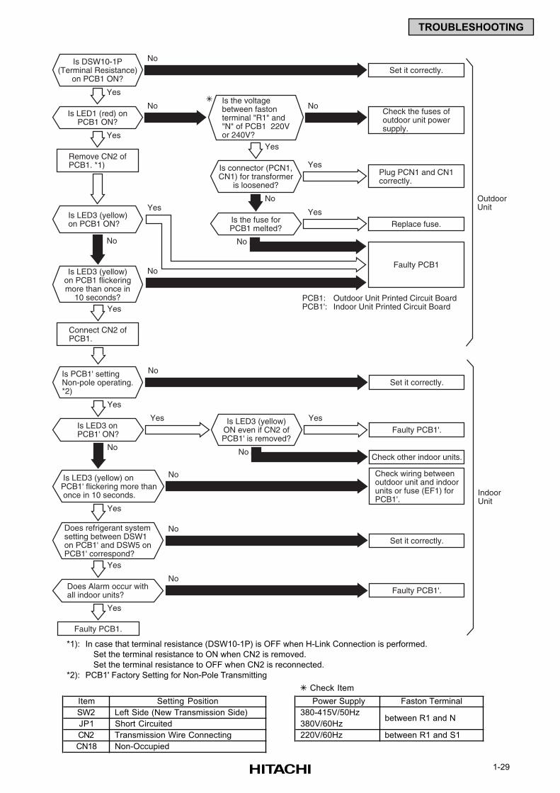
1-29
TROUBLESHOOTING
Is LED3 (yellow)on PCB1 ON?
Is PCB1' settingNon-pole operating.*2)
No
No
Yes
YesYes
Is the voltagebetween fastonterminal "R1" and"N" of PCB1 220Vor 240V?
Is DSW10-1P(Terminal Resistance)
on PCB1 ON?
Is LED3 (yellow)on PCB1 flickeringmore than once in
10 seconds?
No
Is connector (PCN1,CN1) for transformer
is loosened?
Is LED1 (red) onPCB1 ON?
Set it correctly.
No
Remove CN2 ofPCB1. *1)
Yes
Is LED3 onPCB1' ON?
Yes
Is LED3 (yellow) onPCB1' flickering more than once in 10 seconds.
Yes
Connect CN2 ofPCB1.
Faulty PCB1.
Replace fuse.
No
Set it correctly.
Set it correctly.
Faulty PCB1'.
Faulty PCB1'.
YesPlug PCN1 and CN1correctly.
Check the fuses ofoutdoor unit powersupply.
No
Check wiring betweenoutdoor unit and indoorunits or fuse (EF1) forPCB1'.
No
Does refrigerant systemsetting between DSW1on PCB1' and DSW5 onPCB1' correspond?
Yes
No
Does Alarm occur withall indoor units?
Yes
No
Faulty PCB1
PCB1: Outdoor Unit Printed Circuit BoardPCB1': Indoor Unit Printed Circuit Board
OutdoorUnit
Check other indoor units.No
No No
Is the fuse forPCB1 melted?
YesYes
No
Is LED3 (yellow)ON even if CN2 ofPCB1' is removed?
YesYes
IndoorUnit
*1): In case that terminal resistance (DSW10-1P) is OFF when H-Link Connection is performed.
Set the terminal resistance to ON when CN2 is removed.
Set the terminal resistance to OFF when CN2 is reconnected.
*2): PCB1' Factory Setting for Non-Pole Transmitting
Check Item
Item Setting Position Power Supply Faston Terminal
SW2 Left Side (New Transmission Side) 380-415V/50Hz
JP1 Short Circuited 380V/60Hz
CN2 Transmission Wire Connecting 220V/60Hz between R1 and S1
CN18 Non-Occupied
between R1 and N
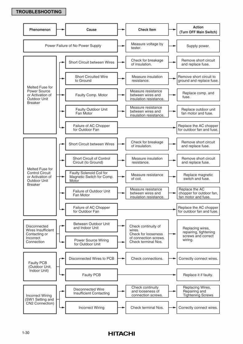
1-30
TROUBLESHOOTING
Cause Check ItemAction
(Turn OFF Main Switch)Phenomenon
Melted Fuse forPower Sourceor Activation ofOutdoor UnitBreaker
Check for breakageof insulation.
Remove short circuitand replace fuse.Short Circuit between Wires
Measure insulationresistance.
Remove short circuit toground and replace fuse.
Short Circuited Wireto Ground
Measure voltage bytester. Supply power.Power Failure of No Power Supply
Measure resistancebetween wires andinsulation resistance.
Replace comp. andfuse.Faulty Comp. Motor
Measure resistancebetween wires andinsulation resistance.
Replace outdoor unitfan motor and fuse.
Faulty Outdoor UnitFan Motor
Replace the AC chopperfor outdoor fan and fuse.
Failure of AC Chopperfor Outdoor Fan
Melted Fuse forControl Circuitor Activation ofOutdoor UnitBreaker
Check for breakageof insulation.
Remove short circuitand replace fuse.Short Circuit between Wires
Measure insulationresistance.
Remove short circuitand replace fuse.
Short Circuit of ControlCircuit (to Ground)
DisconnectedWires InsufficientContacting orIncorrectConnection
Check continuity of wires.Check for loosenessof connection screws.Check terminal Nos.
Replacing wires,repairing, tighteningscrews and correctwiring.
Between Outdoor Unitand Indoor Unit
Power Source Wiringfor Outdoor Unit
Measure resistanceof coil.
Replace magneticswitch and fuse.
Faulty Solenoid Coil forMagnetic Switch for Comp.Motor
Measure resistancebetween wires andinsulation resistance.
Replace the ACchopper for outdoor fan,fan motor and fuse.
Failure of Outdoor UnitFan Motor
Replace the AC chopperfor outdoor fan and fuse.
Correctly connect wires.
Replace it if faulty.
Failure of AC Chopperfor Outdoor Fan
Faulty PCB(Outdoor Unit, Indoor Unit)
Check connections.
Replacing Wires,Repairing andTightening Screws
Correctly connect wires.
Check continuityand looseness ofconnection screws.
Check terminal Nos.
Disconnected Wires to PCB
Faulty PCB
Incorrect Wiring(SW1 Setting and CN2 Connection)
Disconnected WireInsufficient Contacting
Incorrect Wiring
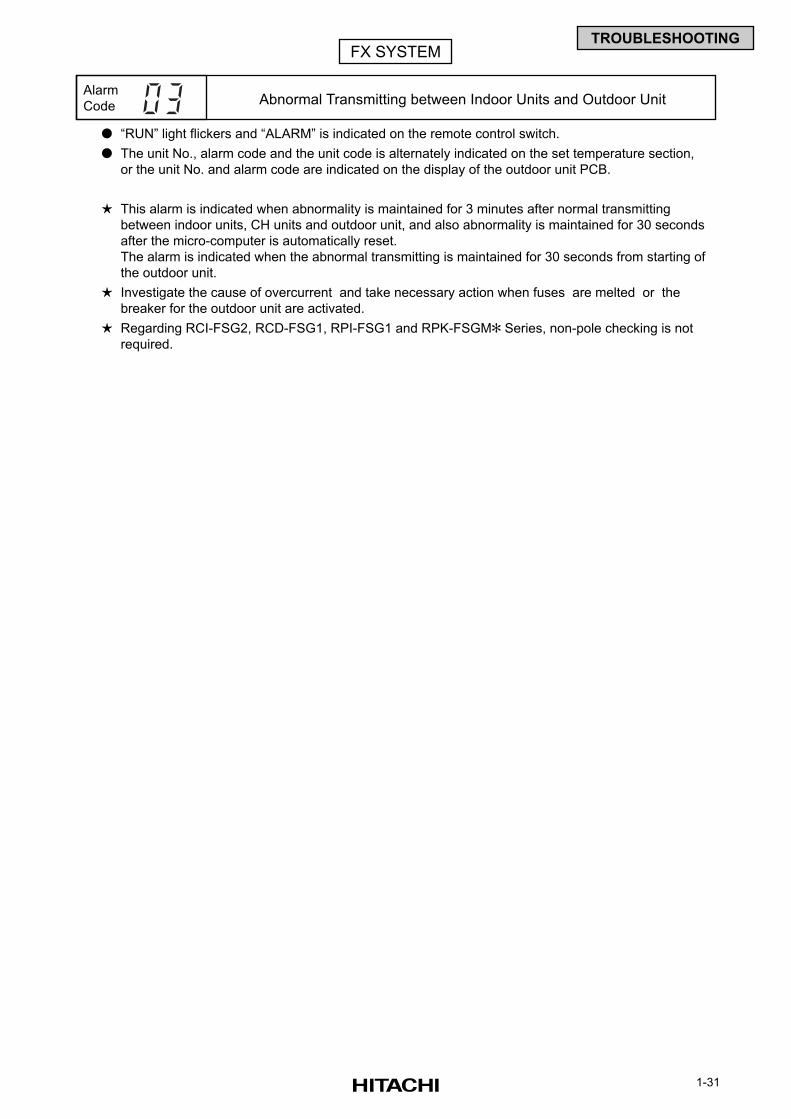
1-31
TROUBLESHOOTING
“RUN” light flickers and “ALARM” is indicated on the remote control switch.
The unit No., alarm code and the unit code is alternately indicated on the set temperature section,
or the unit No. and alarm code are indicated on the display of the outdoor unit PCB.
This alarm is indicated when abnormality is maintained for 3 minutes after normal transmitting
between indoor units, CH units and outdoor unit, and also abnormality is maintained for 30 seconds
after the micro-computer is automatically reset.
The alarm is indicated when the abnormal transmitting is maintained for 30 seconds from starting of
the outdoor unit.
Investigate the cause of overcurrent and take necessary action when fuses are melted or the
breaker for the outdoor unit are activated.
Regarding RCI-FSG2, RCD-FSG1, RPI-FSG1 and RPK-FSGM Series, non-pole checking is not
required.
Alarm
Code Abnormal Transmitting between Indoor Units and Outdoor Unit
FX SYSTEM
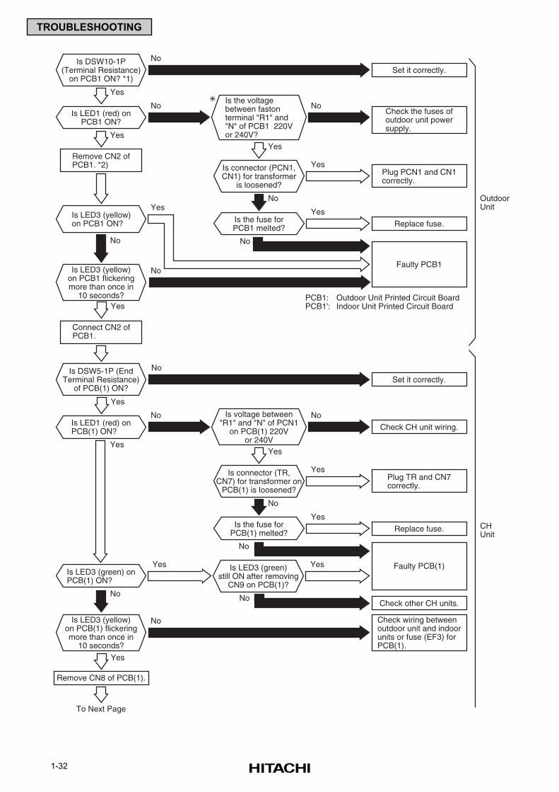
1-32
TROUBLESHOOTING
Is LED3 (yellow)on PCB1 ON?
Is DSW5-1P (EndTerminal Resistance)
of PCB(1) ON?
No
Yes
YesYes
Is the voltagebetween fastonterminal "R1" and"N" of PCB1 220Vor 240V?
Is DSW10-1P(Terminal Resistance)
on PCB1 ON? *1)
Is LED3 (yellow)on PCB1 flickeringmore than once in
10 seconds?
No
Is connector (PCN1,CN1) for transformer
is loosened?
Is LED1 (red) onPCB1 ON?
Set it correctly.
No
Remove CN2 ofPCB1. *2)
Yes
Is LED1 (red) onPCB(1) ON?
Yes
Is LED3 (green) onPCB(1) ON?
Yes
Connect CN2 ofPCB1.
Yes
Remove CN8 of PCB(1).
To Next Page
Replace fuse.
No
No
NoNo
Set it correctly.
Check CH unit wiring.
YesPlug PCN1 and CN1correctly.
Check the fuses ofoutdoor unit powersupply.
No
Check wiring betweenoutdoor unit and indoorunits or fuse (EF3) forPCB(1).
No
Faulty PCB1
PCB1: Outdoor Unit Printed Circuit BoardPCB1': Indoor Unit Printed Circuit Board
OutdoorUnit
No
Is LED3 (yellow)on PCB(1) flickeringmore than once in
10 seconds?
No
No
Is the fuse forPCB1 melted?
Yes
Yes
No
Is connector (TR,CN7) for transformer on
PCB(1) is loosened?
Replace fuse.
Check other CH units.
YesPlug TR and CN7correctly.
Is LED3 (green)still ON after removing
CN9 on PCB(1)?
YesYes
Is the fuse forPCB(1) melted?
Yes
Yes
Is voltage between"R1" and "N" of PCN1
on PCB(1) 220Vor 240V
Faulty PCB(1)
No
No
CHUnit
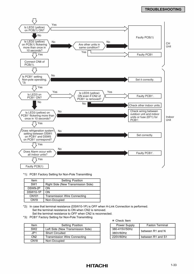
1-33
TROUBLESHOOTING
Is LED3 (yellow) onPCB1' flickering more than
once in 10 seconds?
Is PCB1' settingNon-pole operating.*3)
No
Is LED2 (yellow)on PCB(1) flickeringmore than once in
10 seconds?
Is LED2 (yellow)on PCB(1) ON?
Is LED3 onPCB1' ON?
Faulty PCB(1)
Yes
Yes
Yes
Does Alarm occur withall indoor units?
Yes
Yes
Connect CN8 ofPCB(1).
Faulty PCB(1)
Faulty PCB1
Set it correctly.
Faulty PCB1'.
No No
Check wiring betweenoutdoor unit and indoorunits or fuse (EF1) forPCB1'.
Yes
No
Does refrigeration system setting between DSW1 on PCB1' and DSW5on PCB1' correspond?
No
IndoorUnit
No
No
Are other units insame condition?
Yes
Check other indoor units.
Set correctly.
No
Faulty PCB1'.
Is LED3 (yellow)ON even if CN2 ofPCB1' is removed?
YesYes
No
CHUnit
*1): PCB1 Factory Setting for Non-Pole Transmitting
*2): In case that terminal resistance (DSW10-1P) is OFF when H-Link Connection is performed.
Set the terminal resistance to ON when CN2 is removed.
Set the terminal resistance to OFF when CN2 is reconnected.
*3): PCB1' Factory Setting for Non-Pole Transmitting
Item Setting Position
SW1 Right Side (New Transmission Side)
DSW9-2P ON
DSW10-1P ON
CN101 Transmission Wire Connecting
CN19 Non-Occupied
Check Item
Item Setting Position Power Supply Faston Terminal
SW2 Left Side (New Transmission Side) 380-415V/50Hz
JP1 Short Circuited 380V/60Hz
CN2 Transmission Wire Connecting 220V/60Hz between R1 and S1
CN18 Non-Occupied
between R1 and N
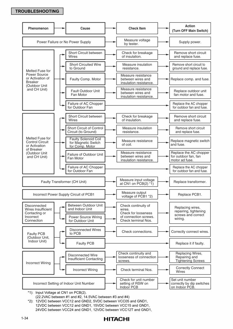
1-34
TROUBLESHOOTING
Cause Check ItemAction
(Turn OFF Main Switch)
Measure voltageby tester. Supply power.
Phenomenon
Short Circuit betweenWires
Melted Fuse forPower Sourceor Activation ofBreaker(Outdoor Unit and CH Unit)
Power Failure or No Power Supply
Check for breakageof insulation.
Remove short circuitand replace fuse.
Short Circuited Wireto Ground
Remove short circuit toground and replace fuse.
Fault Outdoor UnitFan Motor
Measure resistancebetween wires andinsulation resistance.
Replace outdoor unitfan motor and fuse.
Faulty Comp. MotorMeasure resistancebetween wires andinsulation resistance.
Replace comp. and fuse.
Failure of AC Chopperfor Outdoor Fan
Replace the AC chopperfor outdoor fan and fuse.
Measure insulationresistance.
Short Circuit betweenWires
Melted Fuse forControl Circuitor Activationof Breaker(Outdoor Unit and CH Unit)
Check for breakageof insulation.
Remove short circuitand replace fuse.
Short Circuit of ControlCircuit (to Ground)
Remove short circuitand replace fuse.
Failure of Outdoor UnitFan Motor
Measure resistancebetween wires andinsulation resistance.
Replace the AC chopperfor outdoor fan, fanmotor ad fuse.
Faulty Solenoid Coilfor Magnetic Switchfor Comp. Motor
Measure resistanceof coil.
Replace magnetic switchand fuse.
Check continuity andlooseness of connectionscrews.
Replacing Wires,Repairing andTightening Screws
Check terminal Nos. Correctly ConnectWires
Failure of AC Chopperfor Outdoor Fan
Replace the AC chopperfor outdoor fan and fuse.
Measure insulationresistance.
Measure input voltageat CN1 on PCB(2) *1) Replace transformer.
Check connections. Correctly connect wires.
Replace it if faulty.
Faulty Transformer (CH Unit)
Measure outputvoltage of PCB1 *2) Replace PCB1.Incorrect Power Supply Circuit of PCB1
Check for unit numbersetting of RSW onIndoor PCB
Set unit numbercorrectly by dip switcheson Indoor PCB.
Incorrect Setting of Indoor Unit Number
Between Outdoor Unitand Indoor Unit
DisconnectedWires InsufficientContacting orIncorrectConnection
Check continuity ofwires.Check for loosenessof connection screws.Check terminal Nos.
Replacing wires,repairing, tighteningscrews and correctwiring.Power Source Wiring
for Outdoor Unit
Disconnected Wiresto PCBFaulty PCB
(Outdoor Unit, Indoor Unit)
Faulty PCB
Disconnected WireInsufficient Contacting
Incorrect Wiring
Incorrect Wiring
*1): Input Voltage at CN1 on PCB(2).
(22.2VAC between #1 and #2, 14.5VAC between #3 and #4)
*2): 12VDC between VCC12 and GND2, 5VDC between VCC05 and GND1,
12VDC between VCC12 and GND1, 15VDC between VCC15 and GND1,
24VDC between VCC24 and GND1, 12VDC between VCC12T and GND1,
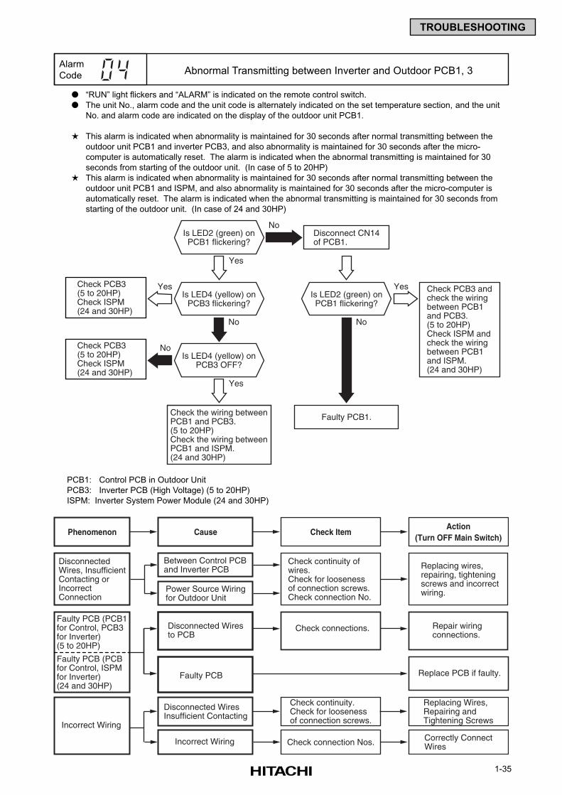
1-35
TROUBLESHOOTING
Yes
Disconnect CN14of PCB1.
Check the wiring betweenPCB1 and PCB3.(5 to 20HP)Check the wiring betweenPCB1 and ISPM.(24 and 30HP)
Check PCB3 (5 to 20HP)Check ISPM (24 and 30HP)
Check PCB3 andcheck the wiringbetween PCB1and PCB3.(5 to 20HP)Check ISPM andcheck the wiringbetween PCB1and ISPM. (24 and 30HP)
Faulty PCB1.
No
No
No
Is LED2 (green) onPCB1 flickering?
Yes
Is LED4 (yellow) onPCB3 OFF?
Is LED4 (yellow) onPCB3 flickering?
YesYes
No
Is LED2 (green) onPCB1 flickering?
Check PCB3 (5 to 20HP)Check ISPM (24 and 30HP)
“RUN” light flickers and “ALARM” is indicated on the remote control switch.
The unit No., alarm code and the unit code is alternately indicated on the set temperature section, and the unit
No. and alarm code are indicated on the display of the outdoor unit PCB1.
This alarm is indicated when abnormality is maintained for 30 seconds after normal transmitting between the
outdoor unit PCB1 and inverter PCB3, and also abnormality is maintained for 30 seconds after the micro-
computer is automatically reset. The alarm is indicated when the abnormal transmitting is maintained for 30
seconds from starting of the outdoor unit. (In case of 5 to 20HP)
This alarm is indicated when abnormality is maintained for 30 seconds after normal transmitting between the
outdoor unit PCB1 and ISPM, and also abnormality is maintained for 30 seconds after the micro-computer is
automatically reset. The alarm is indicated when the abnormal transmitting is maintained for 30 seconds from
starting of the outdoor unit. (In case of 24 and 30HP)
PCB1: Control PCB in Outdoor Unit
PCB3: Inverter PCB (High Voltage) (5 to 20HP)
ISPM: Inverter System Power Module (24 and 30HP)
Alarm
Code Abnormal Transmitting between Inverter and Outdoor PCB1, 3
Cause Check ItemAction
(Turn OFF Main Switch)Phenomenon
Check continuity.Check for loosenessof connection screws.
Replacing Wires,Repairing andTightening Screws
Check connection Nos. Correctly ConnectWires
Check connections. Repair wiringconnections.
Replace PCB if faulty.
Between Control PCBand Inverter PCB
DisconnectedWires, InsufficientContacting orIncorrectConnection
Check continuity ofwires.Check for loosenessof connection screws.Check connection No.
Replacing wires,repairing, tighteningscrews and incorrectwiring.Power Source Wiring
for Outdoor Unit
Disconnected Wiresto PCB
Faulty PCB (PCB1for Control, PCB3for Inverter)(5 to 20HP)
Faulty PCB
Disconnected WiresInsufficient Contacting
Incorrect Wiring
Incorrect Wiring
Faulty PCB (PCBfor Control, ISPMfor Inverter)(24 and 30HP)
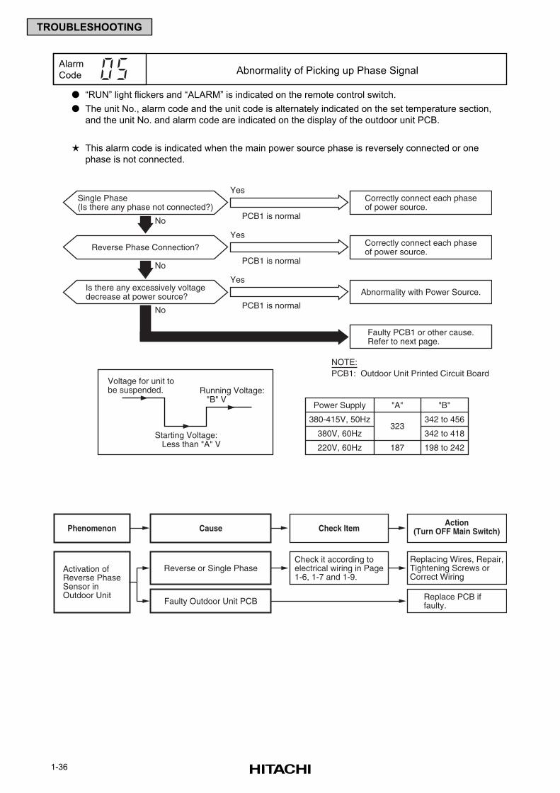
1-36
TROUBLESHOOTING
“RUN” light flickers and “ALARM” is indicated on the remote control switch.
The unit No., alarm code and the unit code is alternately indicated on the set temperature section,
and the unit No. and alarm code are indicated on the display of the outdoor unit PCB.
This alarm code is indicated when the main power source phase is reversely connected or one
phase is not connected.
Alarm
Code Abnormality of Picking up Phase Signal
Correctly connect each phaseof power source.
No
Single Phase(Is there any phase not connected?)
No
Yes
PCB1 is normal
PCB1 is normal
PCB1 is normal
Voltage for unit tobe suspended. Running Voltage:
"B" VPower Supply "A" "B"
187
323342 to 456380-415V, 50Hz
380V, 60Hz
220V, 60Hz
Starting Voltage: Less than "A" V
Abnormality with Power Source.Is there any excessively voltagedecrease at power source?
Yes
Correctly connect each phaseof power source.
Faulty PCB1 or other cause.Refer to next page.
No
Reverse Phase Connection?
Yes
NOTE:PCB1: Outdoor Unit Printed Circuit Board
342 to 418
198 to 242
Cause Check ItemAction
(Turn OFF Main Switch)Phenomenon
Activation ofReverse PhaseSensor inOutdoor Unit
Check it according toelectrical wiring in Page1-6, 1-7 and 1-9.
Replacing Wires, Repair,Tightening Screws orCorrect Wiring
Reverse or Single Phase
Replace PCB iffaulty.Faulty Outdoor Unit PCB
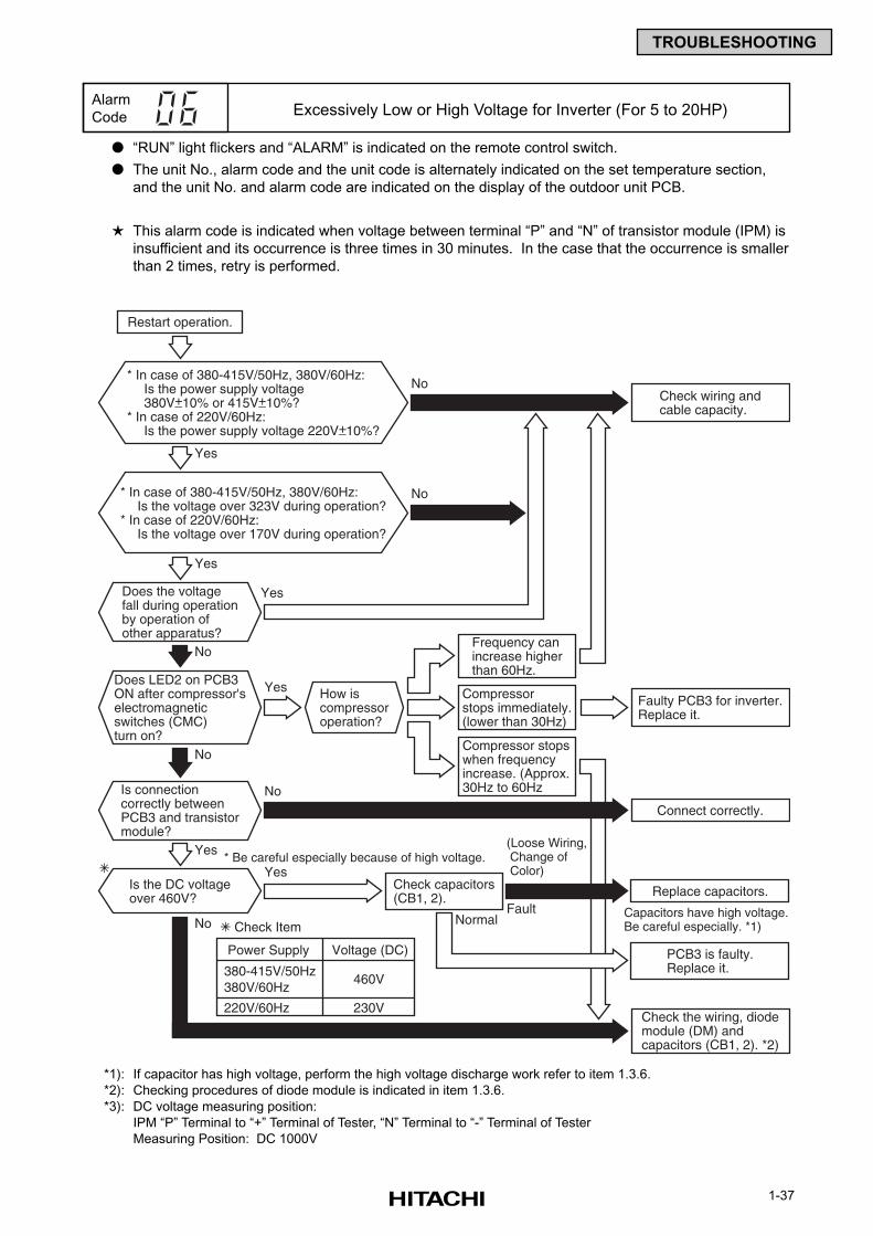
1-37
TROUBLESHOOTING
“RUN” light flickers and “ALARM” is indicated on the remote control switch.
The unit No., alarm code and the unit code is alternately indicated on the set temperature section,
and the unit No. and alarm code are indicated on the display of the outdoor unit PCB.
This alarm code is indicated when voltage between terminal “P” and “N” of transistor module (IPM) is
insufficient and its occurrence is three times in 30 minutes. In the case that the occurrence is smaller
than 2 times, retry is performed.
Alarm
Code Excessively Low or High Voltage for Inverter (For 5 to 20HP)
*1): If capacitor has high voltage, perform the high voltage discharge work refer to item 1.3.6.
*2): Checking procedures of diode module is indicated in item 1.3.6.
*3): DC voltage measuring position:
IPM “P” Terminal to “+” Terminal of Tester, “N” Terminal to “-” Terminal of Tester
Measuring Position: DC 1000V
Does the voltagefall during operationby operation ofother apparatus?
Is connectioncorrectly betweenPCB3 and transistormodule?
Does LED2 on PCB3ON after compressor'selectromagneticswitches (CMC)turn on?
Check capacitors(CB1, 2).
Restart operation.
Check wiring andcable capacity.
Connect correctly.
Replace capacitors.
PCB3 is faulty.Replace it.
Capacitors have high voltage.Be careful especially. *1)
Yes
Yes
Yes
Check the wiring, diodemodule (DM) andcapacitors (CB1, 2). *2)
NormalFault
(Loose Wiring, Change of Color)
Check Item
Frequency canincrease higherthan 60Hz.
Compressorstops immediately.(lower than 30Hz)
Compressor stopswhen frequencyincrease. (Approx.30Hz to 60Hz
How iscompressoroperation?
Yes
Is the DC voltageover 460V?
Yes* Be careful especially because of high voltage.
Yes
No
No
No
No
No
No
* In case of 380-415V/50Hz, 380V/60Hz:Is the voltage over 323V during operation?
* In case of 220V/60Hz:Is the voltage over 170V during operation?
Faulty PCB3 for inverter.Replace it.
220V/60Hz
460V
230V
380-415V/50Hz380V/60Hz
Power Supply Voltage (DC)
* In case of 380-415V/50Hz, 380V/60Hz:Is the power supply voltage380V 10% or 415V 10%?
* In case of 220V/60Hz:Is the power supply voltage 220V 10%?
+_ +_
+_
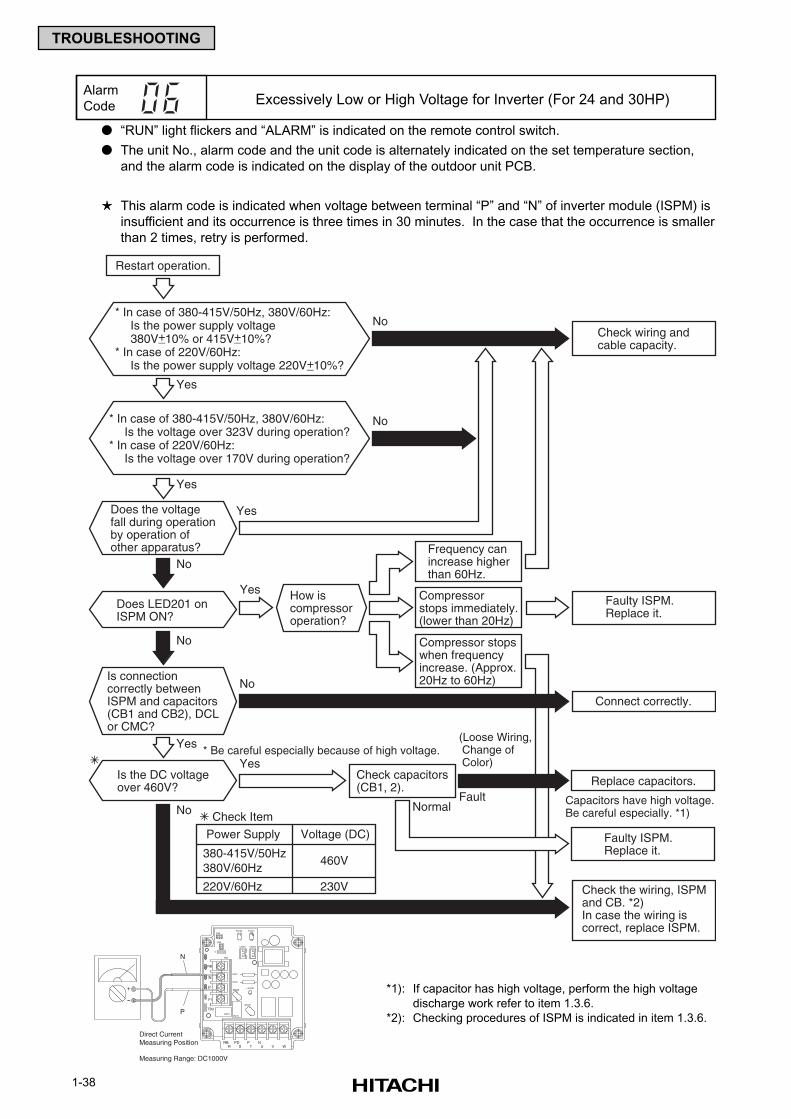
1-38
TROUBLESHOOTING
“RUN” light flickers and “ALARM” is indicated on the remote control switch.
The unit No., alarm code and the unit code is alternately indicated on the set temperature section,
and the alarm code is indicated on the display of the outdoor unit PCB.
This alarm code is indicated when voltage between terminal “P” and “N” of inverter module (ISPM) is
insufficient and its occurrence is three times in 30 minutes. In the case that the occurrence is smaller
than 2 times, retry is performed.
Alarm
Code Excessively Low or High Voltage for Inverter (For 24 and 30HP)
TB3
+
-
N
P
Direct CurrentMeasuring Position
Measuring Range: DC1000V
R S WRB
VT UNPD P
TB2
R216R215
ZN20LED201
ZN202
R201
R200
CN207 CN206
CN9
PC207
C
PC208CN8
RB
N
P
P1
*1): If capacitor has high voltage, perform the high voltage
discharge work refer to item 1.3.6.
*2): Checking procedures of ISPM is indicated in item 1.3.6.
Does the voltagefall during operationby operation ofother apparatus?
Is connectioncorrectly betweenISPM and capacitors(CB1 and CB2), DCLor CMC?
Check capacitors(CB1, 2).
Restart operation.
Check wiring andcable capacity.
Connect correctly.
Replace capacitors.
Faulty ISPM.Replace it.
Capacitors have high voltage.Be careful especially. *1)
Yes
Yes
Yes
Check the wiring, ISPM and CB. *2)In case the wiring iscorrect, replace ISPM.
NormalFault
(Loose Wiring, Change of Color)
Check Item
Frequency canincrease higherthan 60Hz.
Compressorstops immediately.(lower than 20Hz)
Compressor stopswhen frequencyincrease. (Approx.20Hz to 60Hz)
How iscompressoroperation?
Yes
Is the DC voltageover 460V?
Yes* Be careful especially because of high voltage.
Yes
No
No
No
No
No
No
* In case of 380-415V/50Hz, 380V/60Hz:Is the voltage over 323V during operation?
* In case of 220V/60Hz:Is the voltage over 170V during operation?
Faulty ISPM.Replace it.
220V/60Hz
460V
230V
380-415V/50Hz380V/60Hz
Power Supply Voltage (DC)
* In case of 380-415V/50Hz, 380V/60Hz:Is the power supply voltage380V 10% or 415V 10%?
* In case of 220V/60Hz:Is the power supply voltage 220V 10%?
+_ +_
+_
Does LED201 onISPM ON?
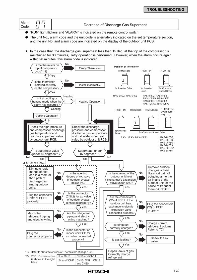
1-39
TROUBLESHOOTING
“RUN” light flickers and “ALARM” is indicated on the remote control switch.
The unit No., alarm code and the unit code is alternately indicated on the set temperature section,
and the unit No. and alarm code are indicated on the display of the outdoor unit PCB.
In the case that the discharge gas superheat less than 15 deg. at the top of the compressor is
maintained for 30 minutes, retry operation is performed. However, when the alarm occurs again
within 90 minutes, this alarm code is indicated.
Alarm
Code Decrease of Discharge Gas Superheat
Is the thermistor ontop of compressorgood? *1)
Is superheat valueunder 15 degrees oC?
Yes
Check the high-pressureand compressor dischargegas temperature andcalculate superheat valueby outdoor unit PCB.
Eliminate rapidchange of heatload in a room orshort path ofdischarged airamong outdoorunits.
Remove suddenchanges of loadlike short path ofoutgoing air to theair intake of theoutdoor unit, or thecause of frequentthermo-ON/OFF.
Faulty Thermistor
No
No
No
Is the thermistorinstalled correctlyon the compressor?
Yes
Install it correctly.
No
Is it at cooling orheating mode when the
alarm has occurred?
Is the openingdegree of ex. valveof outdoor bypass
below 5%?
Is the connector(CN12) for ex. valveof outdoor bypass
connected properly?
Is the connector onindoor unit PCB forex. valve connected
properly?
Are the refrigerantpiping and electricwiring matching?
Is refrigerantcorrectly charged?
Is gas leaking?
Yes
Yes
Yes
Yes
Yes
Yes
Yes
Yes
Superheat: under15 degrees oC?
Cooling
Check the dischargepressure and compressordischarge gas temperatureand calculate superheatvalue by outdoor unit PCB.
Heating Operation
Cooling Operation
Heating
No
Plug the connectors(*2) of PCB1 properly.
No
Charge correctrefrigerant volume.Refer to TCII.
No
Check the ex.valve.
No
Plug the connectorCN12 of PCB1properly.
No
No
No
Match therefrigerant pipingand electric wiring.
Plug theconnector properly.
Repair leaks of gas.Correctly chargerefrigerant.
No
Is the opening of theoutdoor unit heat
exchanger's expansionvalve under 12%?
<FX Series Only>
Are the connectors(*2) of PCB1 of the outdoor unit heat
exchanger's electric expansion valve
connected properly?
Yes
5 to 20HP
24 and 30HP
CN10 and CN11
CN10, CN11, CN12 and CN20
*2): PCB1 Connector No. is shown in the right table.
*1): Refer to "Characteristics of Thermistor" of page 1-53.
Position of Thermistor
THM8(Td1)
for Inverter Drive
RAS-5FSG, RAS-5FS3
THM8(Td1)
for Inverter Drive
RAS-8FSG, RAS-8FS3RAS-10FSG, RAS-10FS3RAS-8FXG, RAS-8FX3RAS-10FXG, RAS-10FX3
THM9(Td2)
for Constant Speed Drive
THM8(Td1)
for Inverter Drive
RAS-16FSG, RAS-16FS3
THM9(Td2)
RAS-20FSG, RAS-20FS3RAS-24FSG1, RAS-24FS5,RAS-30FSG1, RAS-30FS5
THM12(Td3) THM13(Td4)20,24,30HPonly
for Constant Speed Drive
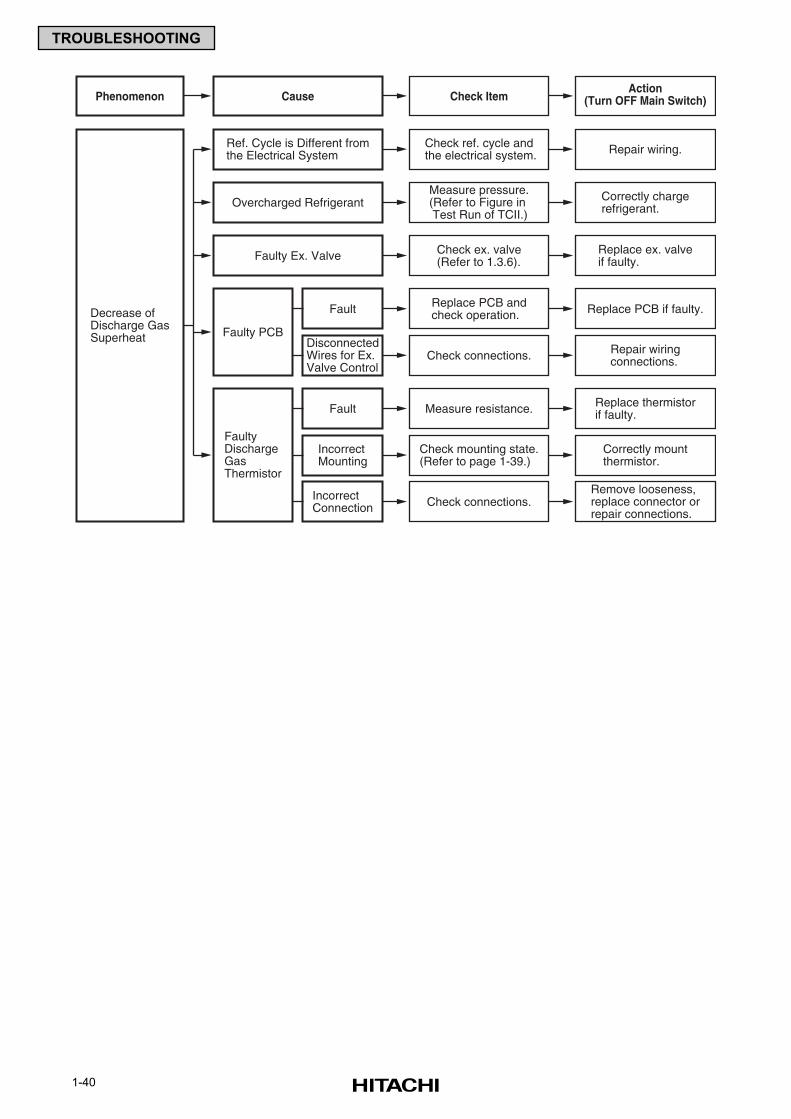
1-40
TROUBLESHOOTING
Cause Check ItemAction
(Turn OFF Main Switch)Phenomenon
Decrease ofDischarge GasSuperheat
Check mounting state.(Refer to page 1-39.)
Measure resistance.
FaultyDischargeGasThermistor
Fault Replace thermistorif faulty.
Correctly mountthermistor.
IncorrectMounting
Check connections.Remove looseness,replace connector orrepair connections.
IncorrectConnection
Check connections.
Replace PCB andcheck operation.
Faulty PCB
Fault Replace PCB if faulty.
Repair wiringconnections.
DisconnectedWires for Ex.Valve Control
Check ref. cycle andthe electrical system. Repair wiring.Ref. Cycle is Different from
the Electrical System
Measure pressure.(Refer to Figure in Test Run of TCII.)
Correctly chargerefrigerant.Overcharged Refrigerant
Check ex. valve(Refer to 1.3.6).
Replace ex. valveif faulty.Faulty Ex. Valve
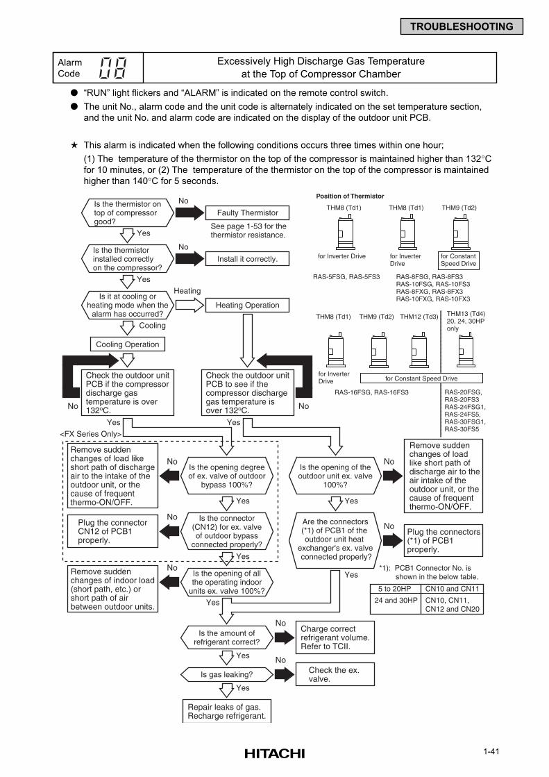
1-41
TROUBLESHOOTING
“RUN” light flickers and “ALARM” is indicated on the remote control switch.
The unit No., alarm code and the unit code is alternately indicated on the set temperature section,
and the unit No. and alarm code are indicated on the display of the outdoor unit PCB.
This alarm is indicated when the following conditions occurs three times within one hour;
(1) The temperature of the thermistor on the top of the compressor is maintained higher than 132°Cfor 10 minutes, or (2) The temperature of the thermistor on the top of the compressor is maintained
higher than 140°C for 5 seconds.
Alarm
Code
Excessively High Discharge Gas Temperature
at the Top of Compressor Chamber
Is the thermistor ontop of compressorgood?
Yes
Check the outdoor unitPCB if the compressordischarge gastemperature is over132oC.
Remove suddenchanges of load likeshort path of dischargeair to the intake of theoutdoor unit, or thecause of frequentthermo-ON/OFF.
Remove suddenchanges of loadlike short path ofdischarge air to theair intake of theoutdoor unit, or thecause of frequentthermo-ON/OFF.
Faulty Thermistor
See page 1-53 for thethermistor resistance.
No
No
No
Is the thermistorinstalled correctlyon the compressor?
Yes
Install it correctly.
No
Is it at cooling orheating mode when the
alarm has occurred?
Is the opening degreeof ex. valve of outdoor
bypass 100%?
Is the connector(CN12) for ex. valveof outdoor bypass
connected properly?
Is the opening of allthe operating indoor
units ex. valve 100%?
Is the amount ofrefrigerant correct?
Is gas leaking?
Yes
Yes Yes
Yes
Yes
Yes
Yes
Yes
Cooling
Check the outdoor unitPCB to see if thecompressor dischargegas temperature isover 132oC.
Heating Operation
Cooling Operation
Heating
No
Plug the connectors(*1) of PCB1 properly.
No
Charge correctrefrigerant volume.Refer to TCII.
No
Check the ex.valve.
No
Plug the connectorCN12 of PCB1properly.
No
NoRemove suddenchanges of indoor load(short path, etc.) orshort path of airbetween outdoor units.
Repair leaks of gas.Recharge refrigerant.
No
Is the opening of theoutdoor unit ex. valve
100%?
<FX Series Only>
Are the connectors(*1) of PCB1 of the outdoor unit heat
exchanger's ex. valve connected properly?
Yes
Position of Thermistor
THM8 (Td1)
for Inverter Drive
RAS-5FSG, RAS-5FS3
THM8 (Td1)
for Inverter Drive
RAS-8FSG, RAS-8FS3RAS-10FSG, RAS-10FS3RAS-8FXG, RAS-8FX3RAS-10FXG, RAS-10FX3
THM9 (Td2)
for Constant Speed Drive
THM8 (Td1)
for Inverter Drive
RAS-16FSG, RAS-16FS3
THM9 (Td2)
RAS-20FSG, RAS-20FS3RAS-24FSG1, RAS-24FS5,RAS-30FSG1, RAS-30FS5
THM12 (Td3) THM13 (Td4)20, 24, 30HPonly
for Constant Speed Drive
5 to 20HP
24 and 30HP
CN10 and CN11
CN10, CN11, CN12 and CN20
*1): PCB1 Connector No. is shown in the below table.
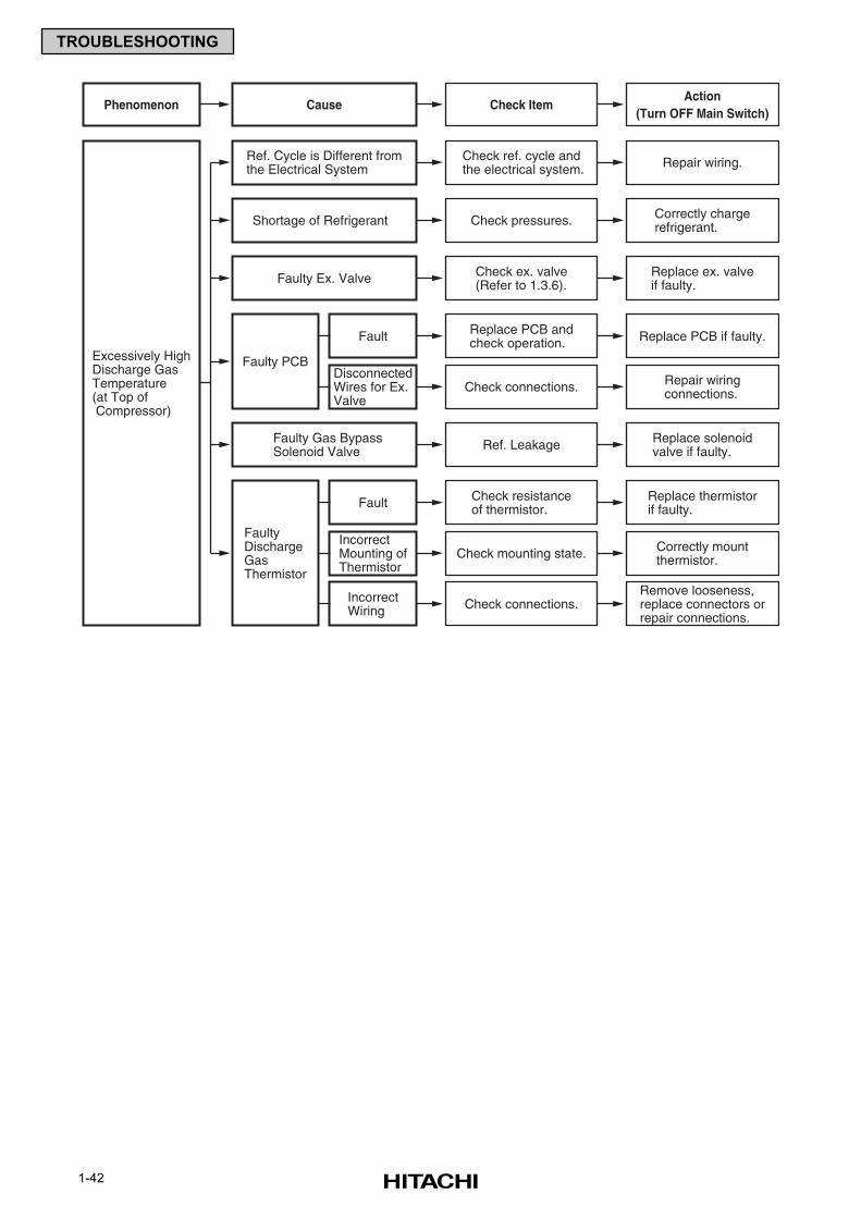
1-42
TROUBLESHOOTING
Cause Check ItemAction
(Turn OFF Main Switch)Phenomenon
Excessively HighDischarge GasTemperature(at Top of Compressor)
Check mounting state.
Check resistanceof thermistor.
FaultyDischargeGasThermistor
Fault Replace thermistorif faulty.
Correctly mountthermistor.
IncorrectMounting ofThermistor
Check connections.Remove looseness,replace connectors orrepair connections.
IncorrectWiring
Check connections.
Replace PCB andcheck operation.
Faulty PCB
Fault Replace PCB if faulty.
Repair wiringconnections.
DisconnectedWires for Ex.Valve
Check ref. cycle andthe electrical system. Repair wiring.Ref. Cycle is Different from
the Electrical System
Ref. Leakage Replace solenoidvalve if faulty.
Faulty Gas BypassSolenoid Valve
Check pressures. Correctly chargerefrigerant.Shortage of Refrigerant
Check ex. valve(Refer to 1.3.6).
Replace ex. valveif faulty.Faulty Ex. Valve
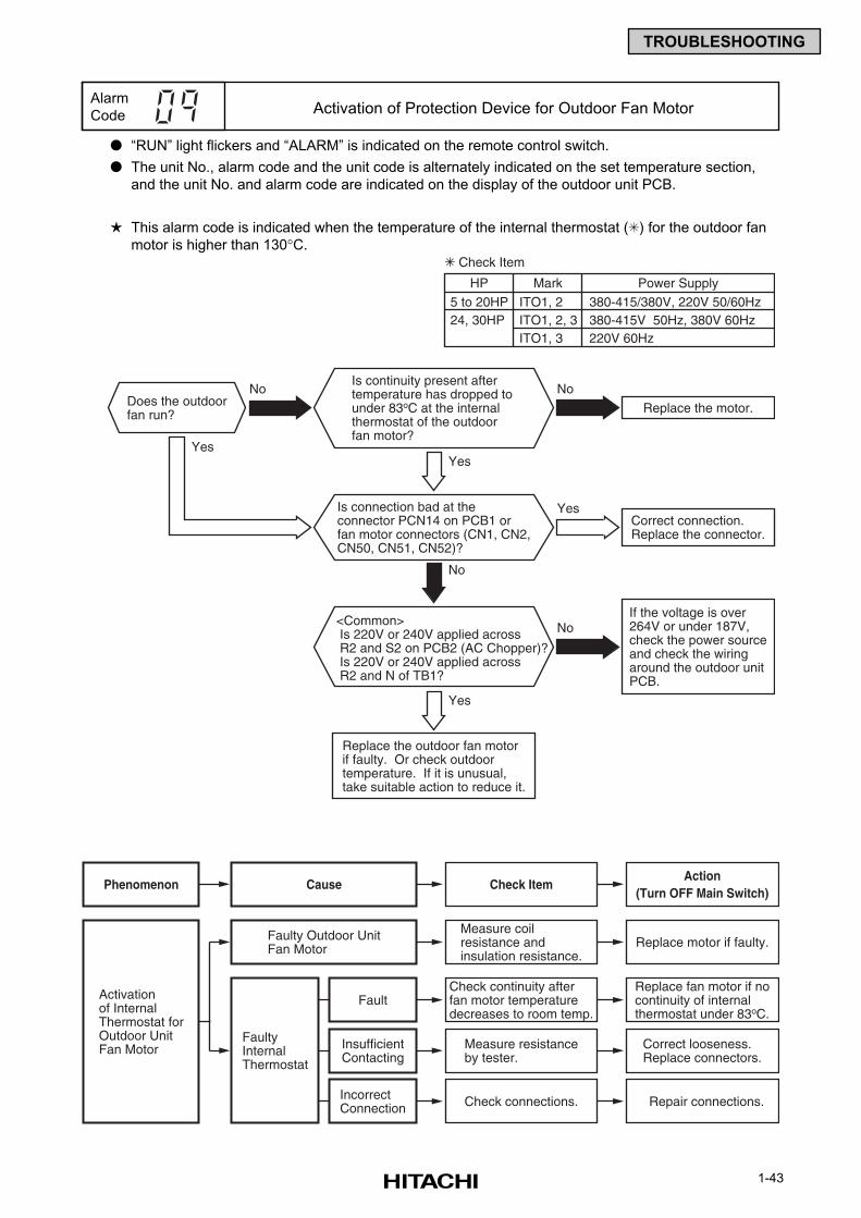
1-43
TROUBLESHOOTING
“RUN” light flickers and “ALARM” is indicated on the remote control switch.
The unit No., alarm code and the unit code is alternately indicated on the set temperature section,
and the unit No. and alarm code are indicated on the display of the outdoor unit PCB.
This alarm code is indicated when the temperature of the internal thermostat () for the outdoor fan
motor is higher than 130°C.
Alarm
Code Activation of Protection Device for Outdoor Fan Motor
Yes
Yes
Replace the motor.
Correct connection.Replace the connector.
If the voltage is over264V or under 187V,check the power sourceand check the wiringaround the outdoor unitPCB.
No No
No
Yes
Yes
Does the outdoorfan run?
Is continuity present aftertemperature has dropped to under 83oC at the internalthermostat of the outdoorfan motor?
Replace the outdoor fan motorif faulty. Or check outdoortemperature. If it is unusual,take suitable action to reduce it.
No<Common> Is 220V or 240V applied across R2 and S2 on PCB2 (AC Chopper)? Is 220V or 240V applied across R2 and N of TB1?
Is connection bad at theconnector PCN14 on PCB1 orfan motor connectors (CN1, CN2,CN50, CN51, CN52)?
Check Item
5 to 20HP ITO1, 2 380-415/380V, 220V 50/60Hz24, 30HP ITO1, 2, 3 380-415V 50Hz, 380V 60Hz
ITO1, 3 220V 60Hz
HP Mark Power Supply
Cause Check ItemAction
(Turn OFF Main Switch)Phenomenon
Activationof InternalThermostat forOutdoor UnitFan Motor Measure resistance
by tester.
Check continuity afterfan motor temperaturedecreases to room temp.
FaultyInternalThermostat
FaultReplace fan motor if nocontinuity of internalthermostat under 83oC.
Correct looseness.Replace connectors.
InsufficientContacting
Check connections. Repair connections.IncorrectConnection
Measure coilresistance andinsulation resistance.
Replace motor if faulty.Faulty Outdoor UnitFan Motor
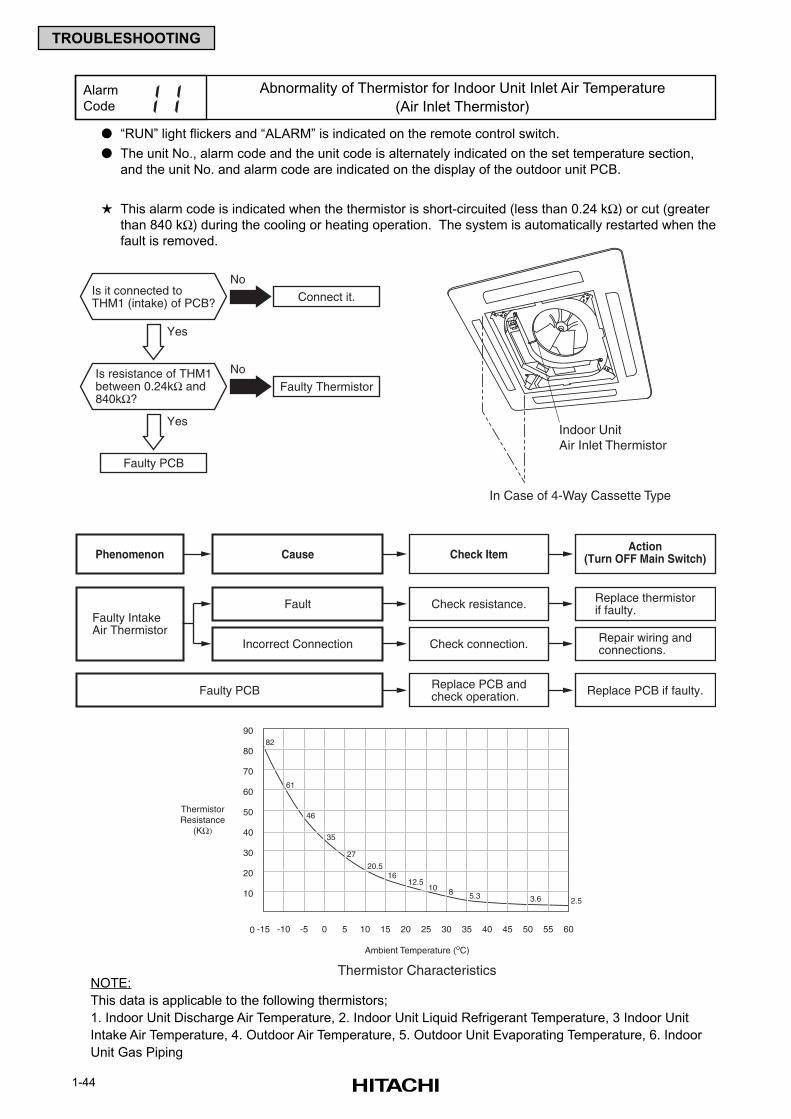
1-44
TROUBLESHOOTING
“RUN” light flickers and “ALARM” is indicated on the remote control switch.
The unit No., alarm code and the unit code is alternately indicated on the set temperature section,
and the unit No. and alarm code are indicated on the display of the outdoor unit PCB.
This alarm code is indicated when the thermistor is short-circuited (less than 0.24 kΩ) or cut (greater
than 840 kΩ) during the cooling or heating operation. The system is automatically restarted when the
fault is removed.
Alarm
Code
Abnormality of Thermistor for Indoor Unit Inlet Air Temperature
(Air Inlet Thermistor)
NOTE:
This data is applicable to the following thermistors;
1. Indoor Unit Discharge Air Temperature, 2. Indoor Unit Liquid Refrigerant Temperature, 3 Indoor Unit
Intake Air Temperature, 4. Outdoor Air Temperature, 5. Outdoor Unit Evaporating Temperature, 6. Indoor
Unit Gas Piping
Indoor UnitAir Inlet Thermistor
In Case of 4-Way Cassette Type
0
10
20
30
40
50
60
70
80
-15 -10 -5 0 5 10 15 20 25 30 35 40 45 50 55 60
82
61
46
35
27
20.516
12.510 8 5.3 3.6 2.5
90
Ambient Temperature (oC)
ThermistorResistance
(KΩ)
Thermistor Characteristics
Yes
Yes
Connect it.
No
Faulty Thermistor
Faulty PCB
No
Is it connected toTHM1 (intake) of PCB?
Is resistance of THM1between 0.24kΩ and840kΩ?
Cause Check ItemAction
(Turn OFF Main Switch)Phenomenon
Faulty IntakeAir Thermistor
Check resistance. Replace thermistorif faulty.Fault
Check connection. Repair wiring andconnections.Incorrect Connection
Replace PCB andcheck operation. Replace PCB if faulty.Faulty PCB
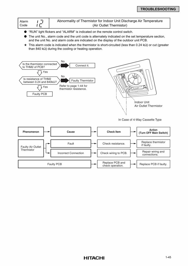
1-45
TROUBLESHOOTING
“RUN” light flickers and “ALARM” is indicated on the remote control switch.
The unit No., alarm code and the unit code is alternately indicated on the set temperature section,
and the unit No. and alarm code are indicated on the display of the outdoor unit PCB.
This alarm code is indicated when the thermistor is short-circuited (less than 0.24 kΩ) or cut (greater
than 840 kΩ) during the cooling or heating operation.
Alarm
Code
Abnormality of Thermistor for Indoor Unit Discharge Air Temperature
(Air Outlet Thermistor)
Yes
Connect it.
No
Refer to page 1-44 forthermistor resistance.
Faulty PCB
Is the thermistor connectedto THM2 of PCB?
Yes
Faulty Thermistor
NoIs resistance of THM2between 0.24 and 840kΩ?
Cause Check ItemAction
(Turn OFF Main Switch)Phenomenon
Faulty Air OutletThermistor
Check resistance. Replace thermistorif faulty.Fault
Check wiring to PCB. Repair wiring andconnections.Incorrect Connection
Replace PCB andcheck operation. Replace PCB if faulty.Faulty PCB
Indoor UnitAir Outlet Thermistor
In Case of 4-Way Cassette Type

1-46
TROUBLESHOOTING
“RUN” light flickers and “ALARM” is indicated on the remote control switch.
The unit No., alarm code and the unit code is alternately indicated on the set temperature section,
and the unit No. and alarm code are indicated on the display of the outdoor unit PCB.
This alarm code is indicated when the thermistor is short-circuited (less than 0.24 kΩ) or cut (greater
than 840 kΩ) during the cooling operation or heating operation.
Alarm
Code
Abnormality of Thermistor for Indoor Unit Heat Exchanger Liquid
Refrigerant Pipe Temperature (Freeze Protection Thermistor)
Yes
Connect it.
No
Refer to page 1-44 forthermistor resistance.
Faulty PCB
Is the thermistor connectedto THM3 of PCB?
Yes
Faulty Thermistor
NoIs resistance of THM3between 0.24 and 840kΩ?
Cause Check ItemAction
(Turn OFF Main Switch)Phenomenon
Faulty FreezeProtectionThermistor
Check resistance. Replace thermistorif faulty.Fault
Check wiring to PCB. Repair wiring andconnections.Incorrect Connection
Replace PCB andcheck operation. Replace PCB if faulty.Faulty PCB
Freeze ProtectionThermistor (THM3)
In Case of 4-Way Cassette Type
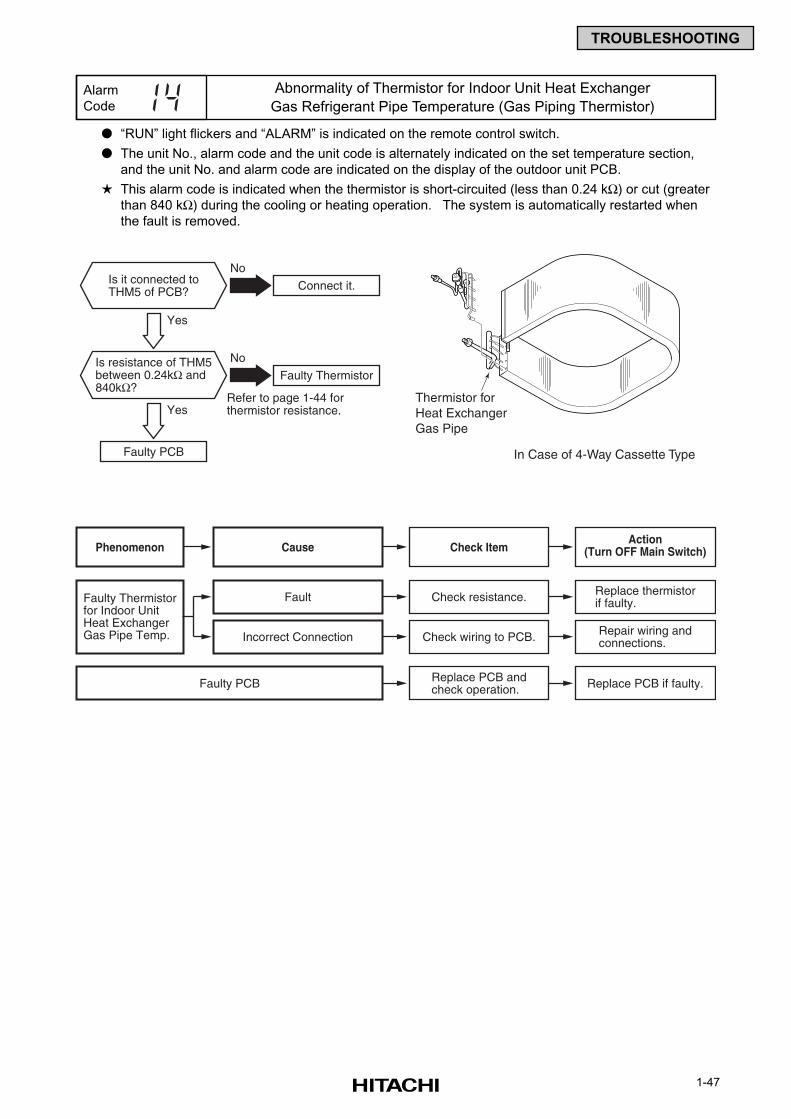
1-47
TROUBLESHOOTING
“RUN” light flickers and “ALARM” is indicated on the remote control switch.
The unit No., alarm code and the unit code is alternately indicated on the set temperature section,
and the unit No. and alarm code are indicated on the display of the outdoor unit PCB.
This alarm code is indicated when the thermistor is short-circuited (less than 0.24 kΩ) or cut (greater
than 840 kΩ) during the cooling or heating operation. The system is automatically restarted when
the fault is removed.
Alarm
Code
Abnormality of Thermistor for Indoor Unit Heat Exchanger
Gas Refrigerant Pipe Temperature (Gas Piping Thermistor)
Refer to page 1-44 forthermistor resistance.
Yes
Yes
Connect it.
No
Faulty Thermistor
Faulty PCB
No
Is it connected toTHM5 of PCB?
Is resistance of THM5between 0.24kΩ and840kΩ?
Cause Check ItemAction
(Turn OFF Main Switch)Phenomenon
Faulty Thermistorfor Indoor UnitHeat ExchangerGas Pipe Temp.
Check resistance. Replace thermistorif faulty.Fault
Check wiring to PCB. Repair wiring andconnections.Incorrect Connection
Replace PCB andcheck operation. Replace PCB if faulty.Faulty PCB
Thermistor for Heat ExchangerGas Pipe
In Case of 4-Way Cassette Type
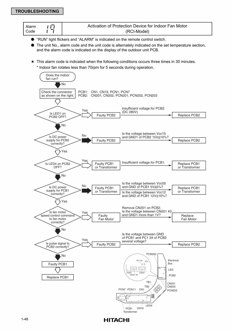
1-48
TROUBLESHOOTING
“RUN” light flickers and “ALARM” is indicated on the remote control switch.
The unit No., alarm code and the unit code is alternately indicated on the set temperature section,
and the alarm code is indicated on the display of the outdoor unit PCB.
This alarm code is indicated when the following conditions occurs three times in 30 minutes.
* Indoor fan rotates less than 70rpm for 5 seconds during operation.
Alarm
Code
Activation of Protection Device for Indoor Fan Motor
(RCI-Model)
Faulty PCB2
Insufficient voltage for PCB2.(DC 280V)
Does the indoorfan run?
Is LED1 onPCB2 OFF?
Check the connectoras shown on the right.
PCB1: CN1, CN19, PCN1, PCN7PCB2: CN201, CN202, PCN201, PCN202, PCN203
Yes
Replace PCB2
No
No
Faulty PCB1
Replace PCB1
Is fan motorspeed control command
to fan motorcorrectly?
Faulty PCB1or Transformer
Insufficient voltage for PCB1.
Faulty PCB1or Transformer
Faulty Fan Motor
Is LED4 on PCB2OFF?
Replace PCB1or Transformer
Replace PCB1or Transformer
ReplaceFan Motor
No
Yes
Faulty PCB2
Is the voltage between GNDof PCB1 and PC1 2# of PCB2several voltage?
Remove CN201 on PCB2.Is the voltage between CN201 #3and GND1 more than 1V?
Is pulse signal toPCB2 correctly?
Replace PCB2
Faulty PCB2Is DC power
supply for PCB2correctly?
Is DC powersupply for PCB1
correctly?
No
Replace PCB2
Yes
Is the voltage between Vcc15and GND1 of PCB2 15V+10%?
Is the voltage between Vcc05and GND of PCB1 5V+5%?
Is the voltage between Vcc12and GND of PCB1 12V+10%?
Yes
No
Yes
No
Yes
No
PCB1
PCB2
ElectricalBox
LED
CN201CN203
PCN203
Transformer
PCN7 PCN11
LED4
CN1
CN19
TB1
TB2
PC1PC1-2#
CN201 CN202CN201-3#
PCN202
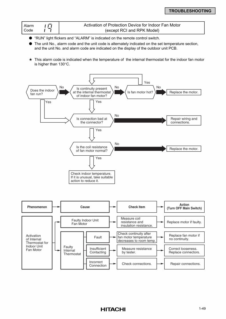
1-49
TROUBLESHOOTING
“RUN” light flickers and “ALARM” is indicated on the remote control switch.
The unit No., alarm code and the unit code is alternately indicated on the set temperature section,
and the unit No. and alarm code are indicated on the display of the outdoor unit PCB.
This alarm code is indicated when the temperature of the internal thermostat for the indoor fan motor
is higher than 130°C.
Alarm
Code
Activation of Protection Device for Indoor Fan Motor
(except RCI and RPK Model)
Yes
Yes
Yes
Yes
Replace the motor.
No No No
Repair wiring andconnections.
No
Replace the motor.
No
Yes
Does the indoorfan run? Is fan motor hot?
Is continuity presentat the internal thermostat
of indoor fan motor?
Is connection bad atthe connector?
Is the coil resistanceof fan motor normal?
Check indoor temperature.If it is unusual, take suitableaction to reduce it.
Cause Check ItemAction
(Turn OFF Main Switch)Phenomenon
Activationof InternalThermostat forIndoor UnitFan Motor Measure resistance
by tester.
Check continuity afterfan motor temperaturedecreases to room temp.
FaultyInternalThermostat
Fault Replace fan motor ifno continuity.
Correct looseness.Replace connectors.
InsufficientContacting
Check connections. Repair connections.IncorrectConnection
Measure coilresistance andinsulation resistance.
Replace motor if faulty.Faulty Indoor UnitFan Motor
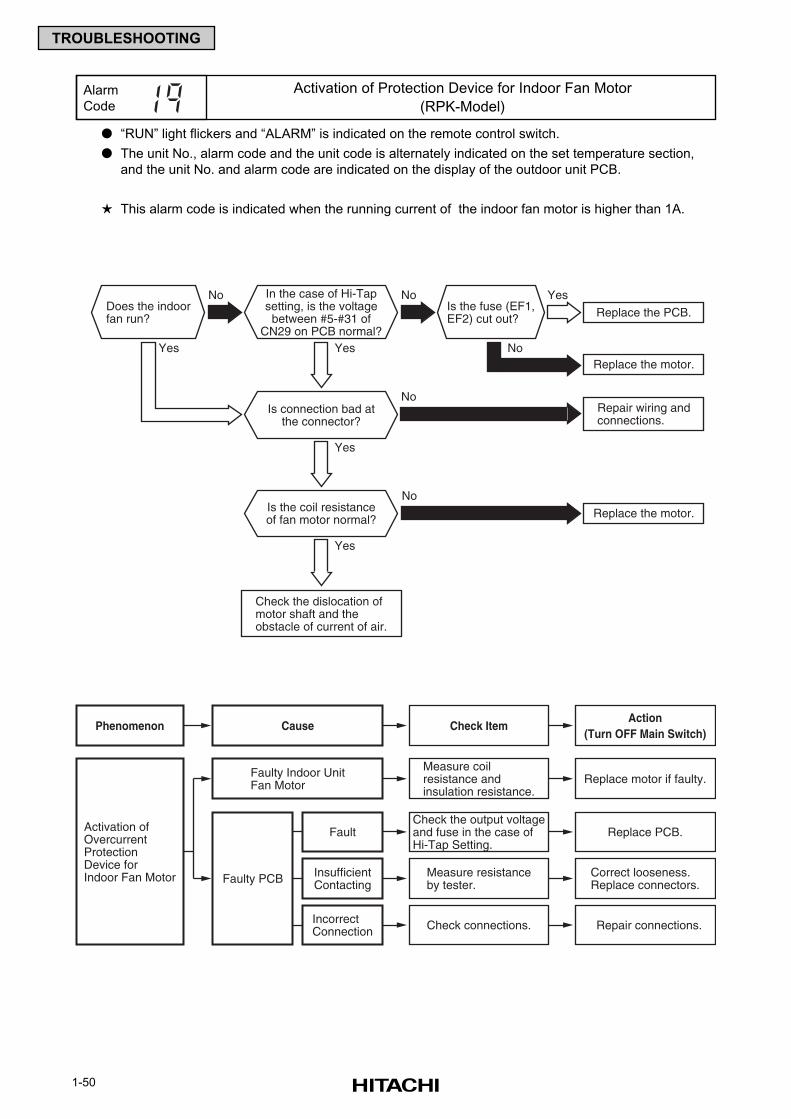
1-50
TROUBLESHOOTING
“RUN” light flickers and “ALARM” is indicated on the remote control switch.
The unit No., alarm code and the unit code is alternately indicated on the set temperature section,
and the unit No. and alarm code are indicated on the display of the outdoor unit PCB.
This alarm code is indicated when the running current of the indoor fan motor is higher than 1A.
Alarm
Code
Activation of Protection Device for Indoor Fan Motor
(RPK-Model)
Yes
Yes
Yes
Yes
Replace the PCB.
No No
Replace the motor.No
Repair wiring andconnections.
No
Replace the motor.
No
Yes
Does the indoorfan run?
Is the fuse (EF1,EF2) cut out?
In the case of Hi-Tapsetting, is the voltagebetween #5-#31 of
CN29 on PCB normal?
Is connection bad atthe connector?
Is the coil resistanceof fan motor normal?
Check the dislocation ofmotor shaft and theobstacle of current of air.
Cause Check ItemAction
(Turn OFF Main Switch)Phenomenon
Activation ofOvercurrentProtectionDevice forIndoor Fan Motor Measure resistance
by tester.
Check the output voltageand fuse in the case ofHi-Tap Setting.
Faulty PCB
Fault Replace PCB.
Correct looseness.Replace connectors.
InsufficientContacting
Check connections. Repair connections.IncorrectConnection
Measure coilresistance andinsulation resistance.
Replace motor if faulty.Faulty Indoor UnitFan Motor
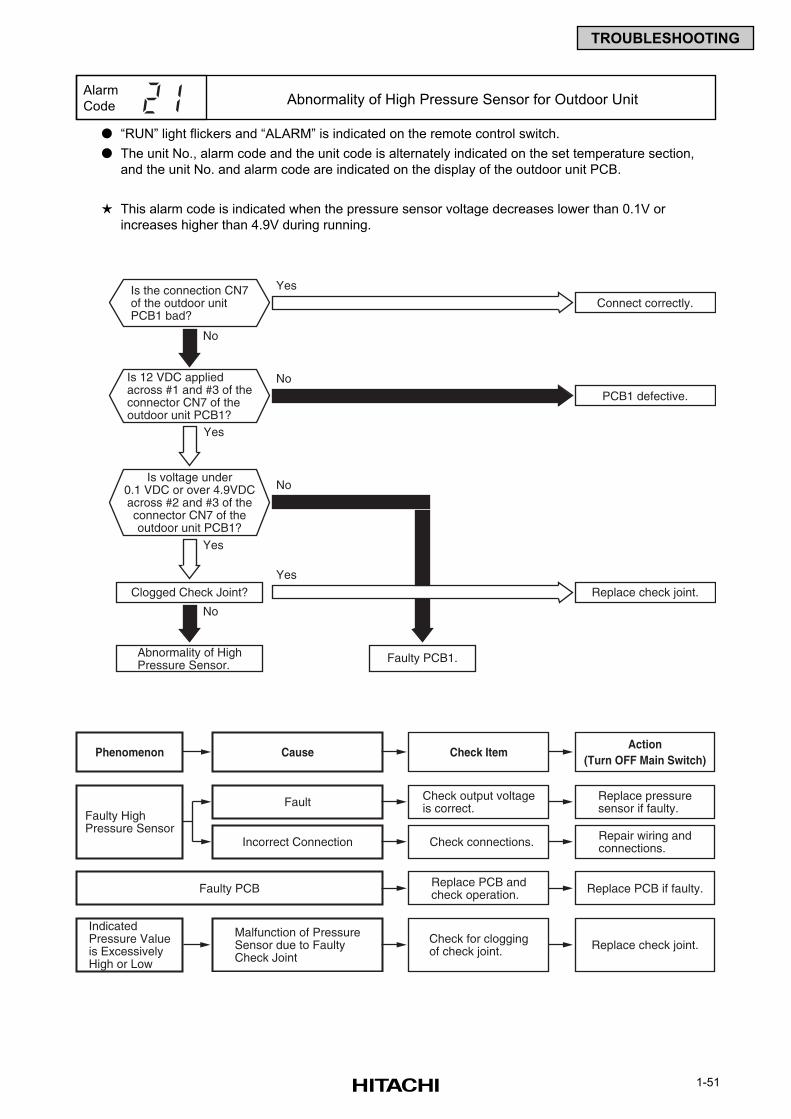
1-51
TROUBLESHOOTING
“RUN” light flickers and “ALARM” is indicated on the remote control switch.
The unit No., alarm code and the unit code is alternately indicated on the set temperature section,
and the unit No. and alarm code are indicated on the display of the outdoor unit PCB.
This alarm code is indicated when the pressure sensor voltage decreases lower than 0.1V or
increases higher than 4.9V during running.
Alarm
Code Abnormality of High Pressure Sensor for Outdoor Unit
Is the connection CN7of the outdoor unitPCB1 bad?
Is 12 VDC appliedacross #1 and #3 of theconnector CN7 of theoutdoor unit PCB1?
Yes
Yes
Is voltage under0.1 VDC or over 4.9VDCacross #2 and #3 of theconnector CN7 of theoutdoor unit PCB1?
Clogged Check Joint?
Abnormality of HighPressure Sensor.
Connect correctly.
PCB1 defective.
Yes
No
No
No
No
Faulty PCB1.
Replace check joint.
Yes
Cause Check ItemAction
(Turn OFF Main Switch)Phenomenon
Faulty HighPressure Sensor
Check output voltageis correct.
Replace pressuresensor if faulty.Fault
IndicatedPressure Valueis ExcessivelyHigh or Low
Check for cloggingof check joint. Replace check joint.
Malfunction of PressureSensor due to FaultyCheck Joint
Check connections. Repair wiring andconnections.Incorrect Connection
Replace PCB andcheck operation. Replace PCB if faulty.Faulty PCB
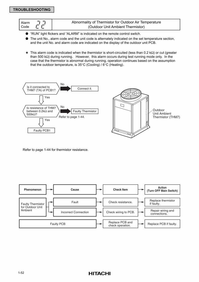
1-52
TROUBLESHOOTING
“RUN” light flickers and “ALARM” is indicated on the remote control switch.
The unit No., alarm code and the unit code is alternately indicated on the set temperature section,
and the unit No. and alarm code are indicated on the display of the outdoor unit PCB.
This alarm code is indicated when the thermistor is short-circuited (less than 0.2 kΩ) or cut (greater
than 500 kΩ) during running. However, this alarm occurs during test running mode only. In the
case that the thermistor is abnormal during running, operation continues based on the assumption
that the outdoor temperature, is 35°C (Cooling) / 6°C (Heating).
Refer to page 1-44 for thermistor resistance.
Alarm
Code
Abnormality of Thermistor for Outdoor Air Temperature
(Outdoor Unit Ambient Thermistor)
Yes
Yes
Connect it.
No
Faulty Thermistor
Refer to page 1-44.
Faulty PCB1
No
Is it connected toTHM7 (TA) of PCB1?
Is resistance of THM7between 0.2kΩ and500kΩ?
Cause Check ItemAction
(Turn OFF Main Switch)Phenomenon
Faulty Thermistorfor Outdoor UnitAmbient
Check resistance. Replace thermistorif faulty.Fault
Check wiring to PCB. Repair wiring andconnections.Incorrect Connection
Replace PCB andcheck operation. Replace PCB if faulty.Faulty PCB
OutdoorUnit AmbientThermistor (THM7)
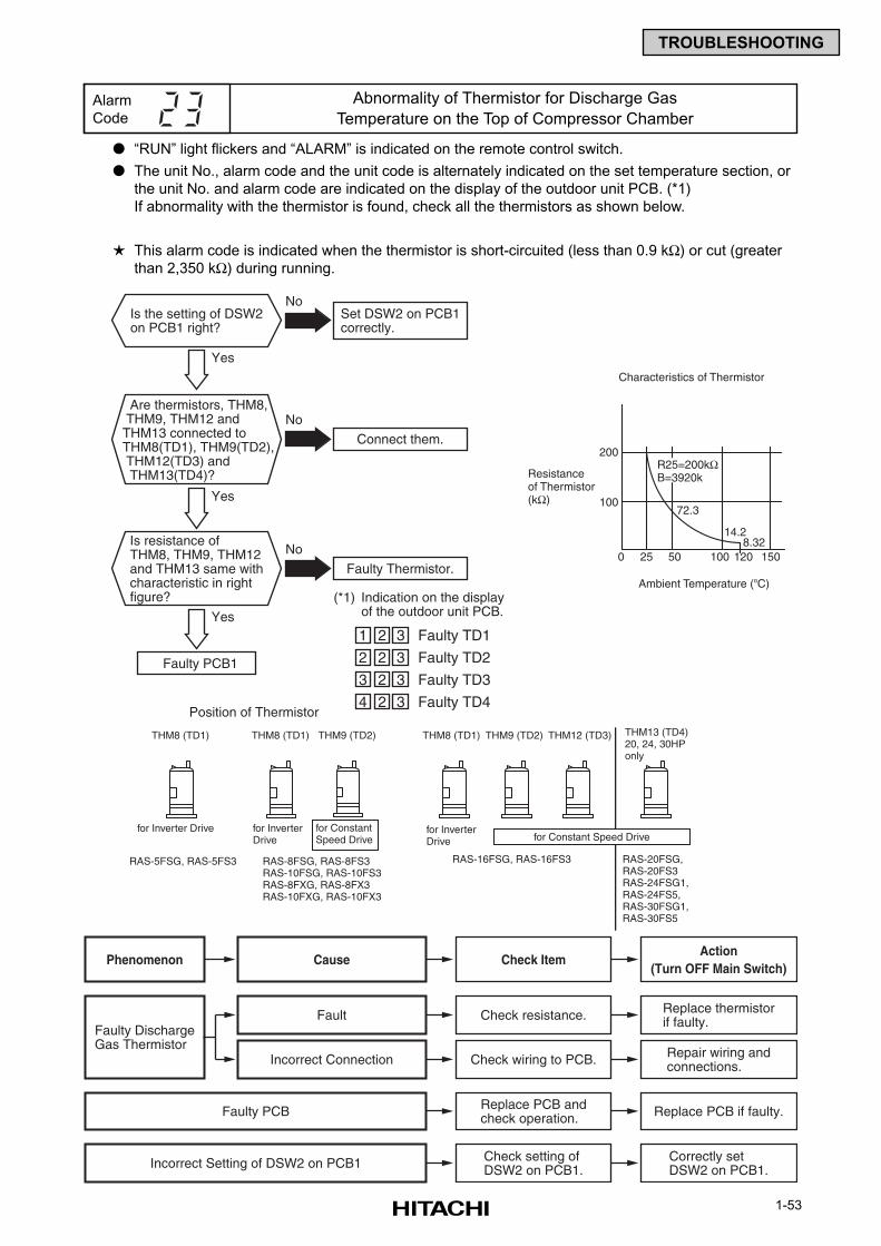
1-53
TROUBLESHOOTING
“RUN” light flickers and “ALARM” is indicated on the remote control switch.
The unit No., alarm code and the unit code is alternately indicated on the set temperature section, or
the unit No. and alarm code are indicated on the display of the outdoor unit PCB. (*1)
If abnormality with the thermistor is found, check all the thermistors as shown below.
This alarm code is indicated when the thermistor is short-circuited (less than 0.9 kΩ) or cut (greater
than 2,350 kΩ) during running.
Alarm
Code
Abnormality of Thermistor for Discharge Gas
Temperature on the Top of Compressor Chamber
Cause Check ItemAction
(Turn OFF Main Switch)Phenomenon
Faulty DischargeGas Thermistor
Check resistance. Replace thermistorif faulty.Fault
Check wiring to PCB. Repair wiring andconnections.Incorrect Connection
Replace PCB andcheck operation. Replace PCB if faulty.Faulty PCB
Check setting ofDSW2 on PCB1.
Correctly setDSW2 on PCB1.Incorrect Setting of DSW2 on PCB1
Yes
Yes
Set DSW2 on PCB1correctly.
No
Connect them.
No
Faulty Thermistor.
No
Position of Thermistor
(*1) Indication on the displayof the outdoor unit PCB.
Faulty PCB1
Is the setting of DSW2on PCB1 right?
Are thermistors, THM8, THM9, THM12 andTHM13 connected toTHM8(TD1), THM9(TD2), THM12(TD3) and THM13(TD4)?
Yes
Is resistance ofTHM8, THM9, THM12and THM13 same withcharacteristic in rightfigure?
1 2 3 Faulty TD1
2 2 3 Faulty TD2
3 2 3 Faulty TD3
4 2 3 Faulty TD4
THM8 (TD1)
for Inverter Drive
RAS-5FSG, RAS-5FS3
THM8 (TD1)
for Inverter Drive
RAS-8FSG, RAS-8FS3RAS-10FSG, RAS-10FS3RAS-8FXG, RAS-8FX3RAS-10FXG, RAS-10FX3
THM9 (TD2)
for Constant Speed Drive
THM8 (TD1)
for Inverter Drive
RAS-16FSG, RAS-16FS3
THM9 (TD2)
RAS-20FSG, RAS-20FS3RAS-24FSG1, RAS-24FS5,RAS-30FSG1, RAS-30FS5
THM12 (TD3) THM13 (TD4)20, 24, 30HPonly
for Constant Speed Drive
200
100
R25=200kΩB=3920k
72.3
14.28.32
0 25 50 100 120 150
Ambient Temperature (oC)
Resistanceof Thermistor(kΩ)
Characteristics of Thermistor
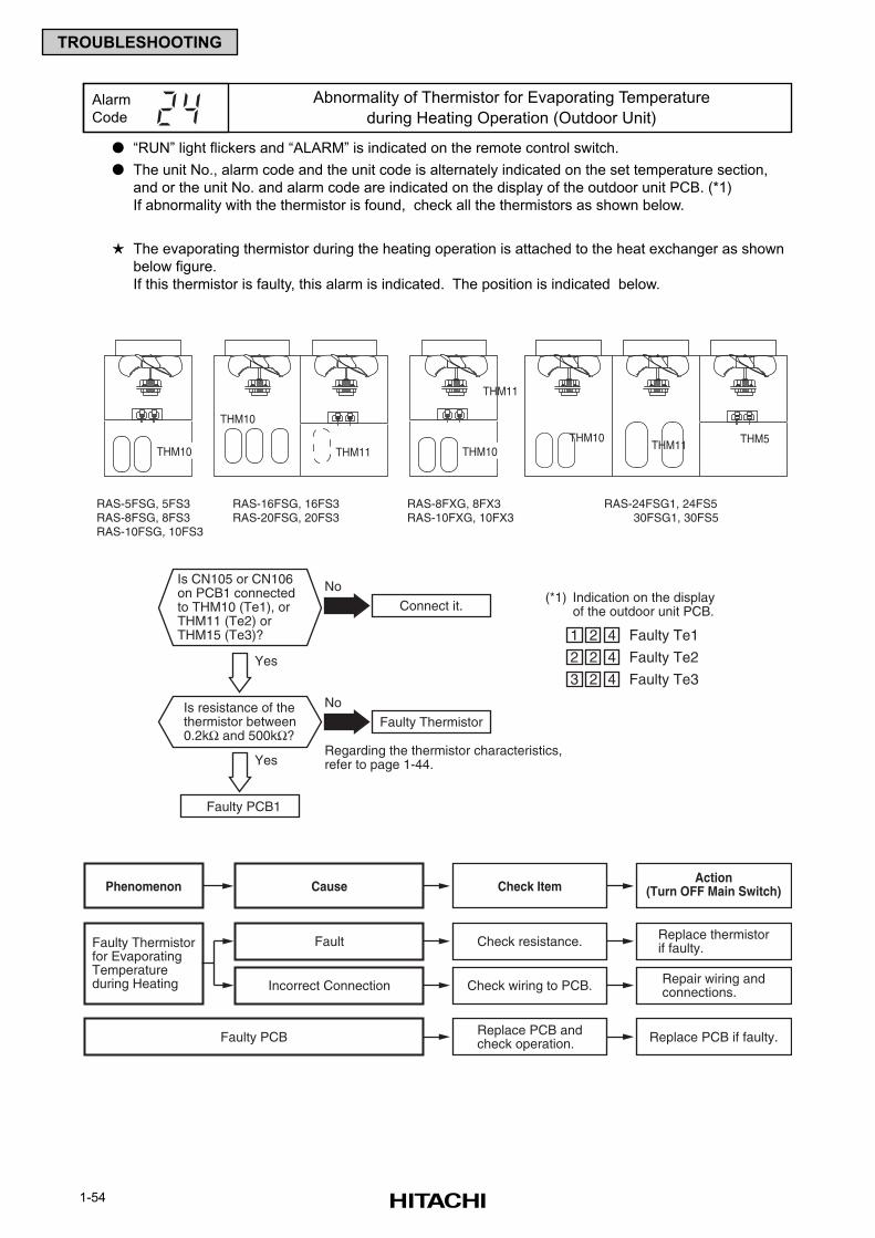
1-54
TROUBLESHOOTING
“RUN” light flickers and “ALARM” is indicated on the remote control switch.
The unit No., alarm code and the unit code is alternately indicated on the set temperature section,
and or the unit No. and alarm code are indicated on the display of the outdoor unit PCB. (*1)
If abnormality with the thermistor is found, check all the thermistors as shown below.
The evaporating thermistor during the heating operation is attached to the heat exchanger as shown
below figure.
If this thermistor is faulty, this alarm is indicated. The position is indicated below.
Alarm
Code
Abnormality of Thermistor for Evaporating Temperature
during Heating Operation (Outdoor Unit)
Yes
Yes
Connect it.
No
Faulty Thermistor
Regarding the thermistor characteristics,refer to page 1-44.
Faulty PCB1
No
Is CN105 or CN106on PCB1 connectedto THM10 (Te1), or THM11 (Te2) or THM15 (Te3)?
Is resistance of thethermistor between0.2kΩ and 500kΩ?
(*1) Indication on the displayof the outdoor unit PCB.
1 2 4 Faulty Te1
2 2 4 Faulty Te2
3 2 4 Faulty Te3
Cause Check ItemAction
(Turn OFF Main Switch)Phenomenon
Faulty Thermistorfor EvaporatingTemperatureduring Heating
Check resistance. Replace thermistorif faulty.Fault
Check wiring to PCB. Repair wiring andconnections.Incorrect Connection
Replace PCB andcheck operation. Replace PCB if faulty.Faulty PCB
RAS-5FSG, 5FS3RAS-8FSG, 8FS3RAS-10FSG, 10FS3
RAS-8FXG, 8FX3RAS-10FXG, 10FX3
RAS-16FSG, 16FS3RAS-20FSG, 20FS3
THM10
THM11THM10
RAS-24FSG1, 24FS5 30FSG1, 30FS5
THM10
THM11
THM11 THM5THM10
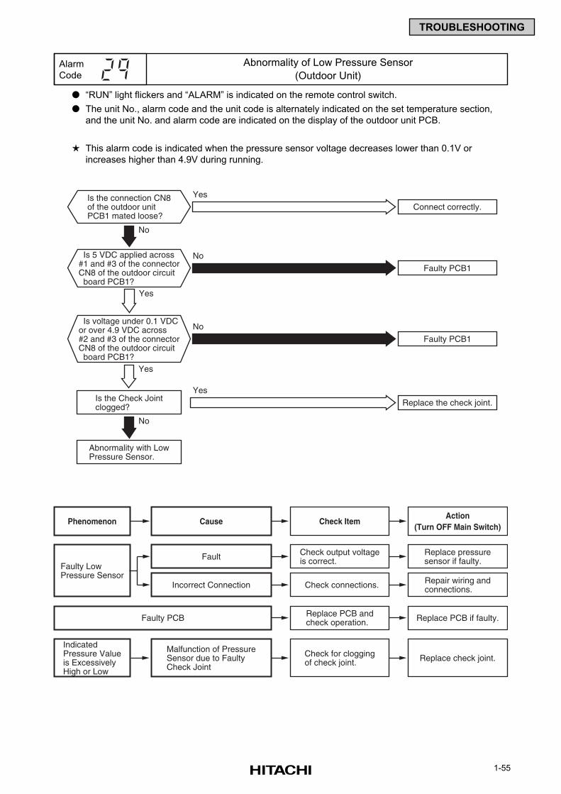
1-55
TROUBLESHOOTING
“RUN” light flickers and “ALARM” is indicated on the remote control switch.
The unit No., alarm code and the unit code is alternately indicated on the set temperature section,
and the unit No. and alarm code are indicated on the display of the outdoor unit PCB.
This alarm code is indicated when the pressure sensor voltage decreases lower than 0.1V or
increases higher than 4.9V during running.
Alarm
Code
Abnormality of Low Pressure Sensor
(Outdoor Unit)
Cause Check ItemAction
(Turn OFF Main Switch)Phenomenon
Faulty LowPressure Sensor
Check output voltageis correct.
Replace pressuresensor if faulty.Fault
IndicatedPressure Valueis ExcessivelyHigh or Low
Check for cloggingof check joint. Replace check joint.
Malfunction of PressureSensor due to FaultyCheck Joint
Check connections. Repair wiring andconnections.Incorrect Connection
Replace PCB andcheck operation. Replace PCB if faulty.Faulty PCB
Is the connection CN8of the outdoor unitPCB1 mated loose?
Is 5 VDC applied across#1 and #3 of the connectorCN8 of the outdoor circuit board PCB1?
Is voltage under 0.1 VDCor over 4.9 VDC across#2 and #3 of the connectorCN8 of the outdoor circuit board PCB1?
Yes
Yes
Is the Check Jointclogged?
Abnormality with LowPressure Sensor.
Connect correctly.
Faulty PCB1
Yes
No
Faulty PCB1
No
No
No
Replace the check joint.
Yes
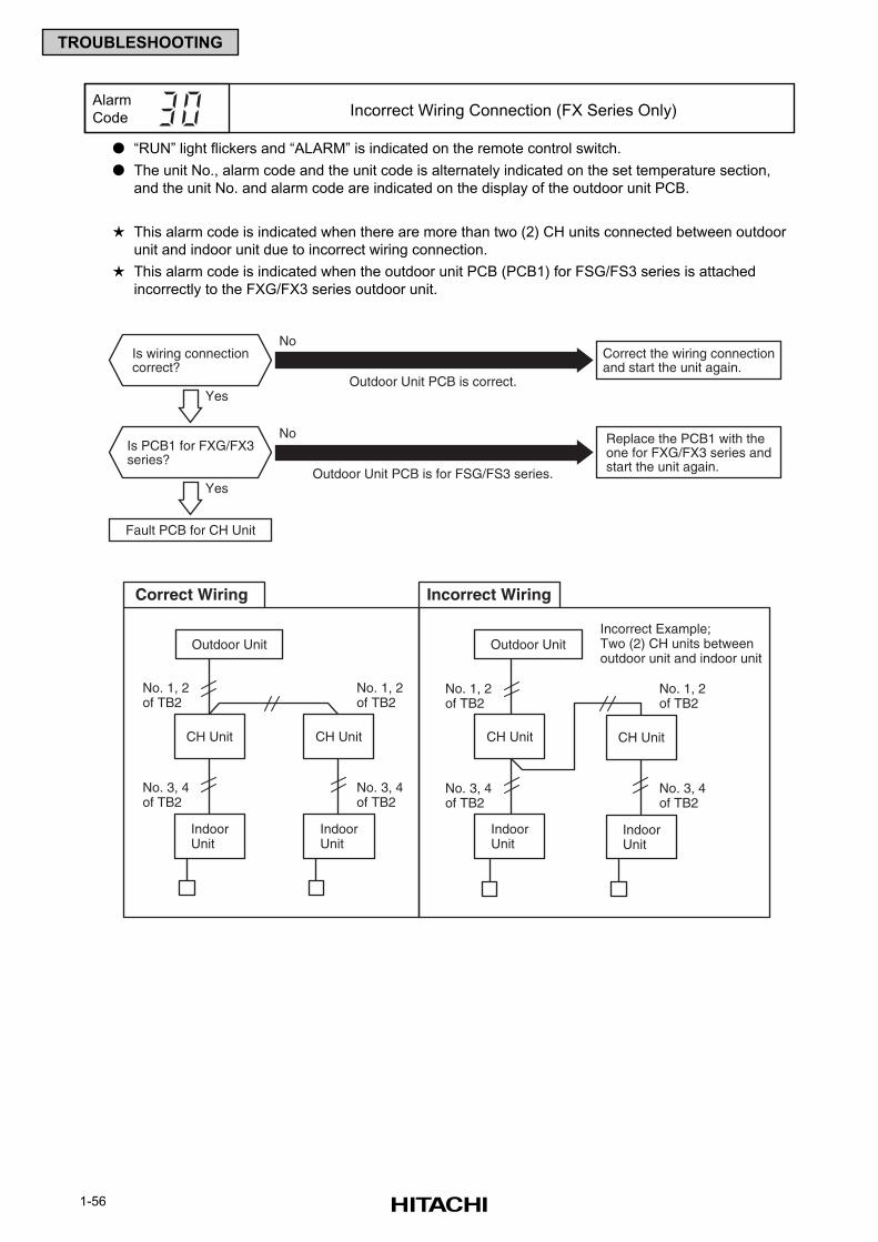
1-56
TROUBLESHOOTING
“RUN” light flickers and “ALARM” is indicated on the remote control switch.
The unit No., alarm code and the unit code is alternately indicated on the set temperature section,
and the unit No. and alarm code are indicated on the display of the outdoor unit PCB.
This alarm code is indicated when there are more than two (2) CH units connected between outdoor
unit and indoor unit due to incorrect wiring connection.
This alarm code is indicated when the outdoor unit PCB (PCB1) for FSG/FS3 series is attached
incorrectly to the FXG/FX3 series outdoor unit.
Alarm
Code Incorrect Wiring Connection (FX Series Only)
Is wiring connectioncorrect?
Yes
Is PCB1 for FXG/FX3series?
Yes
Fault PCB for CH Unit
Correct the wiring connectionand start the unit again.
Outdoor Unit PCB is correct.
Outdoor Unit PCB is for FSG/FS3 series.
No
Replace the PCB1 with theone for FXG/FX3 series andstart the unit again.
No
Correct Wiring
No. 1, 2of TB2
No. 3, 4of TB2
CH Unit
IndoorUnit
Outdoor Unit
IndoorUnit
CH Unit
No. 1, 2of TB2
No. 3, 4of TB2
Incorrect Wiring
No. 1, 2of TB2
No. 3, 4of TB2
IndoorUnit
Outdoor Unit
IndoorUnit
No. 1, 2of TB2
No. 3, 4of TB2
Incorrect Example;Two (2) CH units betweenoutdoor unit and indoor unit
CH Unit CH Unit
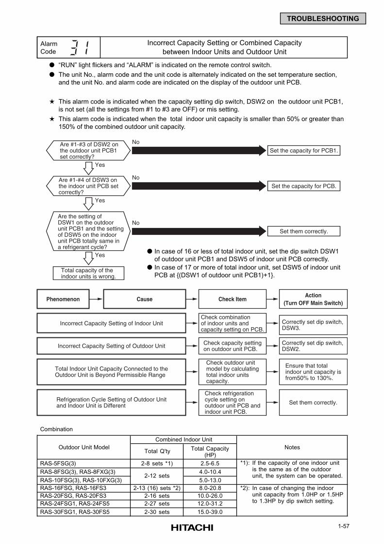
1-57
TROUBLESHOOTING
“RUN” light flickers and “ALARM” is indicated on the remote control switch.
The unit No., alarm code and the unit code is alternately indicated on the set temperature section,
and the unit No. and alarm code are indicated on the display of the outdoor unit PCB.
This alarm code is indicated when the capacity setting dip switch, DSW2 on the outdoor unit PCB1,
is not set (all the settings from #1 to #3 are OFF) or mis setting.
This alarm code is indicated when the total indoor unit capacity is smaller than 50% or greater than
150% of the combined outdoor unit capacity.
Alarm
Code
Incorrect Capacity Setting or Combined Capacity
between Indoor Units and Outdoor Unit
Are #1-#3 of DSW2 onthe outdoor unit PCB1set correctly?
Are the setting ofDSW1 on the outdoorunit PCB1 and the settingof DSW5 on the indoorunit PCB totally same ina refrigerant cycle?
Total capacity of theindoor units is wrong.
Set the capacity for PCB1.
No
Yes
Yes
Yes
Are #1-#4 of DSW3 onthe indoor unit PCB setcorrectly?
Set the capacity for PCB.
No
Set them correctly.
No
Cause Check ItemAction
(Turn OFF Main Switch)Phenomenon
Check combinationof indoor units andcapacity setting on PCB.
Correctly set dip switch,DSW3.
Incorrect Capacity Setting of Indoor Unit
Check outdoor unitmodel by calculatingtotal indoor unitscapacity.
Ensure that totalindoor unit capacity isfrom50% to 130%.
Total Indoor Unit Capacity Connected to theOutdoor Unit is Beyond Permissible Range
Check refrigerationcycle setting onoutdoor unit PCB andindoor unit PCB.
Set them correctly.Refrigeration Cycle Setting of Outdoor Unitand Indoor Unit is Different
Check capacity settingon outdoor unit PCB.
Correctly set dip switch,DSW2.Incorrect Capacity Setting of Outdoor Unit
In case of 16 or less of total indoor unit, set the dip switch DSW1
of outdoor unit PCB1 and DSW5 of indoor unit PCB correctly.
In case of 17 or more of total indoor unit, set DSW5 of indoor unit
PCB at (DSW1 of outdoor unit PCB1)+1.
Combination
Total Q'ty Total Capacity(HP)
RAS-5FSG(3) 2-8 sets *1) 2.5-6.5 *1):
RAS-8FSG(3), RAS-8FXG(3) 4.0-10.4
RAS-10FSG(3), RAS-10FXG(3) 5.0-13.0
RAS-16FSG, RAS-16FS3 2-13 (16) sets *2) 8.0-20.8 *2):
RAS-20FSG, RAS-20FS3 2-16 sets 10.0-26.0
RAS-24FSG1, RAS-24FS5 2-27 sets 12.0-31.2
RAS-30FSG1, RAS-30FS5 2-30 sets 15.0-39.0
In case of changing the indoorunit capacity from 1.0HP or 1.5HPto 1.3HP by dip switch setting.
Outdoor Unit Model
Combined Indoor Unit
Notes
2-12 sets
If the capacity of one indoor unitis the same as of the outdoorunit, the system can be operated.
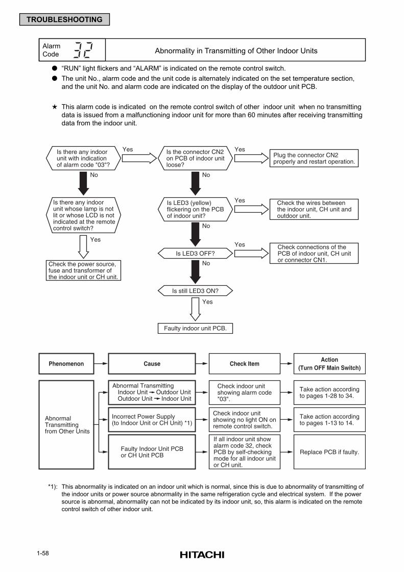
1-58
TROUBLESHOOTING
“RUN” light flickers and “ALARM” is indicated on the remote control switch.
The unit No., alarm code and the unit code is alternately indicated on the set temperature section,
and the unit No. and alarm code are indicated on the display of the outdoor unit PCB.
This alarm code is indicated on the remote control switch of other indoor unit when no transmitting
data is issued from a malfunctioning indoor unit for more than 60 minutes after receiving transmitting
data from the indoor unit.
Alarm
Code Abnormality in Transmitting of Other Indoor Units
Yes
Plug the connector CN2properly and restart operation.
No No
YesIs there any indoorunit with indicationof alarm code "03"?
YesIs the connector CN2on PCB of indoor unitloose?
YesIs LED3 (yellow)flickering on the PCBof indoor unit?
No
Check connections of thePCB of indoor unit, CH unitor connector CN1.
Check the wires betweenthe indoor unit, CH unit andoutdoor unit.
Yes
Is LED3 OFF?
No
Is still LED3 ON?
Is there any indoorunit whose lamp is notlit or whose LCD is notindicated at the remotecontrol switch?
Check the power source,fuse and transformer ofthe indoor unit or CH unit.
Yes
Faulty indoor unit PCB.
Cause Check ItemAction
(Turn OFF Main Switch)Phenomenon
If all indoor unit showalarm code 32, checkPCB by self-checkingmode for all indoor unitor CH unit.
Replace PCB if faulty.Faulty Indoor Unit PCBor CH Unit PCB
AbnormalTransmittingfrom Other Units
Check indoor unitshowing alarm code"03".
Take action accordingto pages 1-28 to 34.
Abnormal TransmittingIndoor Unit Outdoor UnitOutdoor Unit Indoor Unit
Check indoor unitshowing no light ON onremote control switch.
Incorrect Power Supply(to Indoor Unit or CH Unit) *1)
Take action accordingto pages 1-13 to 14.
*1): This abnormality is indicated on an indoor unit which is normal, since this is due to abnormality of transmitting of
the indoor units or power source abnormality in the same refrigeration cycle and electrical system. If the power
source is abnormal, abnormality can not be indicated by its indoor unit, so, this alarm is indicated on the remote
control switch of other indoor unit.
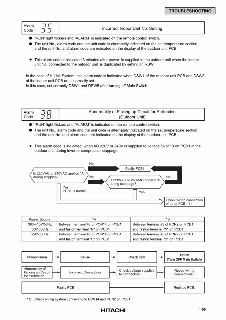
1-59
TROUBLESHOOTING
“RUN” light flickers and “ALARM” is indicated on the remote control switch.
The unit No., alarm code and the unit code is alternately indicated on the set temperature section,
and the unit No. and alarm code are indicated on the display of the outdoor unit PCB.
This alarm code is indicated 3 minutes after power is supplied to the outdoor unit when the indoor
unit No. connected to the outdoor unit is duplicated by setting of RSW.
In the case of H-Link System, this alarm code is indicated when DSW1 of the outdoor unit PCB and DSW5
of the indoor unit PCB are incorrectly set.
In this case, set correctly DSW1 and DSW5 after turning off Main Switch.
“RUN” light flickers and “ALARM” is indicated on the remote control switch.
The unit No., alarm code and the unit code is alternately indicated on the set temperature section,
and the unit No. and alarm code are indicated on the display of the outdoor unit PCB.
This alarm code is indicated when AC 220V or 240V is supplied to voltage *A or *B on PCB1 in the
outdoor unit during inverter compressor stoppage.
Alarm
Code
Abnormality of Picking up Circuit for Protection
(Outdoor Unit)
Alarm
Code Incorrect Indoor Unit No. Setting
Faulty PCB1
Check wiring connectionof other PCB. *1)
No No
No
YesYesPCB1 is normal
Is 220VAC or 240VAC applied *Aduring stopping?
Is 220VAC or 240VAC applied *Bduring stoppage?
Cause Check ItemAction
(Turn OFF Main Switch)Phenomenon
Abnormality ofPicking up Circuitfor Protection
Check voltage suppliedto connectors.
Repair wiringconnections.Incorrect Connection
Faulty PCB Replace PCB.
*1): Check wiring system connecting to PCN14 and PCN2 on PCB1.
Power Supply *A *B
380-415V/50Hz Between terminal #3 of PCN14 on PCB1 Between terminal #3 of PCN2 on PCB1
380V/60Hz and faston terminal "N" on PCB1 and faston terminal "N" on PCB1
220V/60Hz Between terminal #3 of PCN14 on PCB1 Between terminal #3 of PCN2 on PCB1
and faston terminal "S" on PCB1 and faston terminal "S" on PCB1
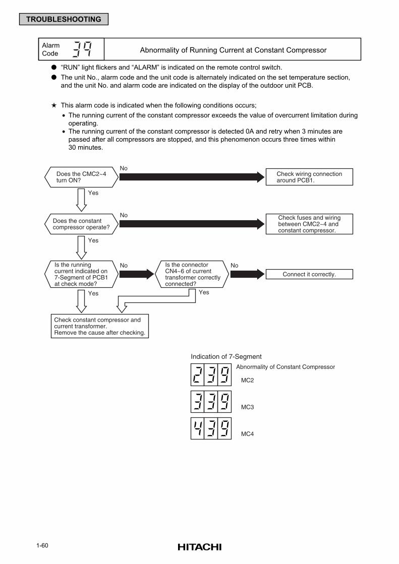
1-60
TROUBLESHOOTING
“RUN” light flickers and “ALARM” is indicated on the remote control switch.
The unit No., alarm code and the unit code is alternately indicated on the set temperature section,
and the unit No. and alarm code are indicated on the display of the outdoor unit PCB.
This alarm code is indicated when the following conditions occurs;
• The running current of the constant compressor exceeds the value of overcurrent limitation during
operating.
• The running current of the constant compressor is detected 0A and retry when 3 minutes are
passed after all compressors are stopped, and this phenomenon occurs three times within
30 minutes.
Alarm
Code Abnormality of Running Current at Constant Compressor
Connect it correctly.
No No
Yes
Yes Yes
Yes
Does the CMC2~4turn ON?
Does the constantcompressor operate?
Is the runningcurrent indicated on7-Segment of PCB1at check mode?
Is the connectorCN4~6 of currenttransformer correctlyconnected?
NoCheck wiring connectionaround PCB1.
No Check fuses and wiringbetween CMC2~4 andconstant compressor.
Check constant compressor andcurrent transformer.Remove the cause after checking.
Indication of 7-Segment
Abnormality of Constant Compressor
MC2
MC3
MC4
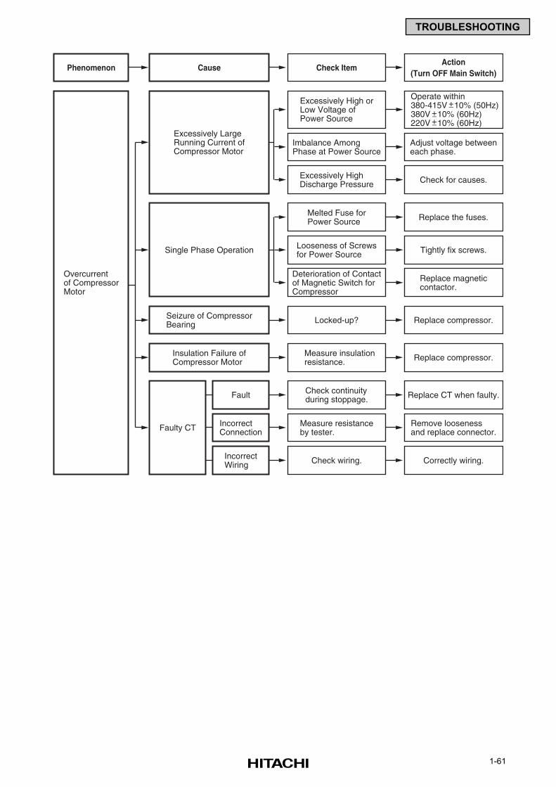
1-61
TROUBLESHOOTING
Cause Check ItemAction
(Turn OFF Main Switch)Phenomenon
Check continuityduring stoppage.
Faulty CT
Replace CT when faulty.Fault
Measure resistanceby tester.
Remove loosenessand replace connector.
IncorrectConnection
Check wiring. Correctly wiring.IncorrectWiring
Imbalance AmongPhase at Power Source
Excessively High orLow Voltage ofPower Source
Excessively LargeRunning Current ofCompressor Motor
Adjust voltage betweeneach phase.
Excessively HighDischarge Pressure
Operate within380-415V 10% (50Hz)380V 10% (60Hz)220V 10% (60Hz)
+−+−+−
Check for causes.
Overcurrentof CompressorMotor
Locked-up? Replace compressor.Seizure of CompressorBearing
Looseness of Screwsfor Power SourceSingle Phase Operation Tightly fix screws.
Deterioration of Contactof Magnetic Switch forCompressor
Replace magneticcontactor.
Measure insulationresistance. Replace compressor.Insulation Failure of
Compressor Motor
Melted Fuse forPower Source Replace the fuses.
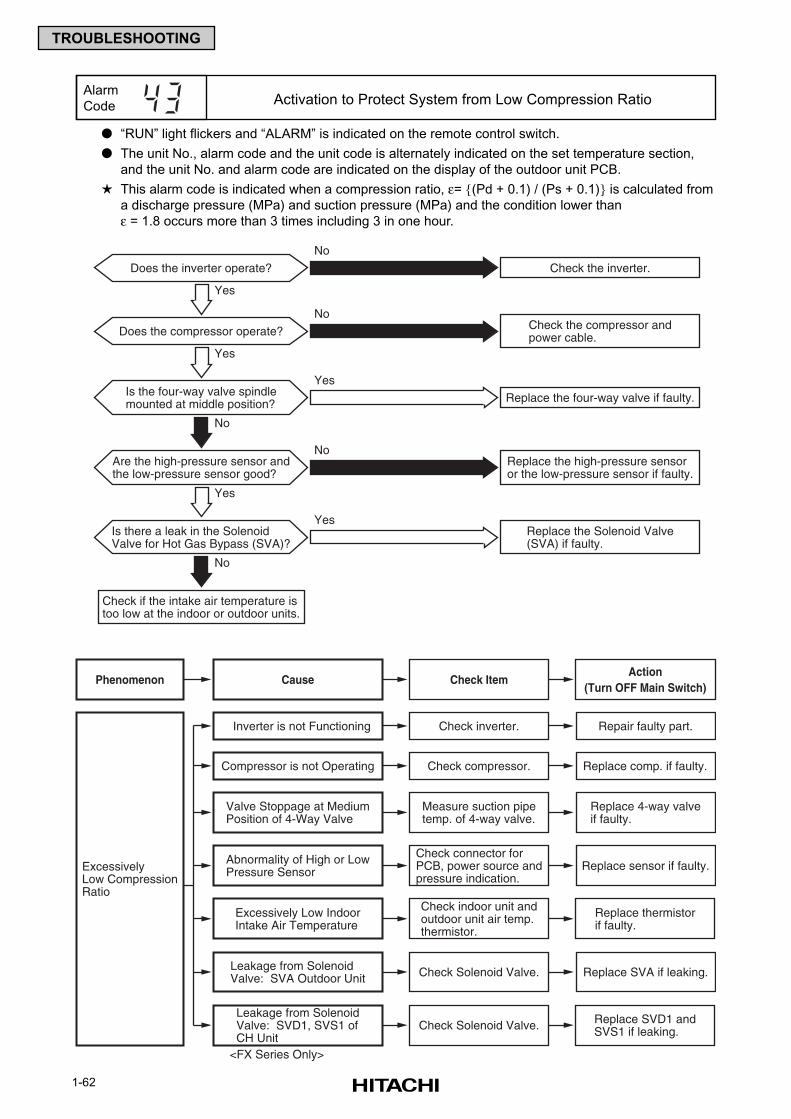
1-62
TROUBLESHOOTING
“RUN” light flickers and “ALARM” is indicated on the remote control switch.
The unit No., alarm code and the unit code is alternately indicated on the set temperature section,
and the unit No. and alarm code are indicated on the display of the outdoor unit PCB.
This alarm code is indicated when a compression ratio, ε= (Pd + 0.1) / (Ps + 0.1) is calculated from
a discharge pressure (MPa) and suction pressure (MPa) and the condition lower than
ε = 1.8 occurs more than 3 times including 3 in one hour.
Alarm
Code
Does the inverter operate?
Yes
Does the compressor operate?
Is the four-way valve spindlemounted at middle position?
Are the high-pressure sensor andthe low-pressure sensor good?
Yes
Check if the intake air temperature istoo low at the indoor or outdoor units.
Replace the high-pressure sensoror the low-pressure sensor if faulty.
Check the compressor andpower cable.
Check the inverter.
Replace the four-way valve if faulty.
No
No
No
No
Is there a leak in the SolenoidValve for Hot Gas Bypass (SVA)?
Yes
No
Yes
Replace the Solenoid Valve(SVA) if faulty.
Yes
Cause Check ItemAction
(Turn OFF Main Switch)Phenomenon
ExcessivelyLow CompressionRatio
Check compressor. Replace comp. if faulty.Compressor is not Operating
Check inverter. Repair faulty part.Inverter is not Functioning
Measure suction pipetemp. of 4-way valve.
Replace 4-way valveif faulty.
Valve Stoppage at MediumPosition of 4-Way Valve
Check connector forPCB, power source andpressure indication.
Replace sensor if faulty.Abnormality of High or LowPressure Sensor
Check indoor unit andoutdoor unit air temp.thermistor.
Replace thermistorif faulty.
Excessively Low IndoorIntake Air Temperature
Check Solenoid Valve.
<FX Series Only>
Replace SVA if leaking.Leakage from SolenoidValve: SVA Outdoor Unit
Check Solenoid Valve. Replace SVD1 andSVS1 if leaking.
Leakage from SolenoidValve: SVD1, SVS1 ofCH Unit
Activation to Protect System from Low Compression Ratio
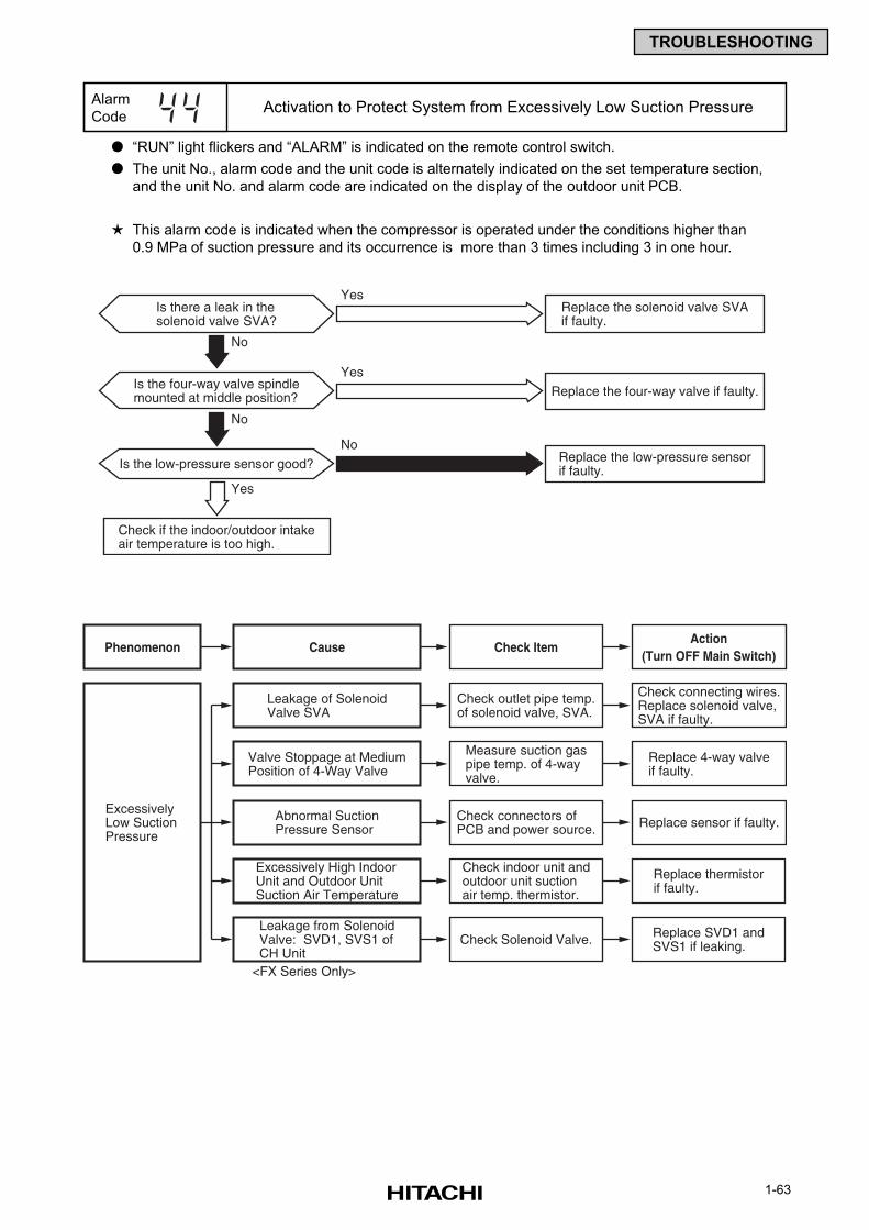
1-63
TROUBLESHOOTING
“RUN” light flickers and “ALARM” is indicated on the remote control switch.
The unit No., alarm code and the unit code is alternately indicated on the set temperature section,
and the unit No. and alarm code are indicated on the display of the outdoor unit PCB.
This alarm code is indicated when the compressor is operated under the conditions higher than
0.9 MPa of suction pressure and its occurrence is more than 3 times including 3 in one hour.
Alarm
CodeActivation to Protect System from Excessively Low Suction Pressure
Is there a leak in thesolenoid valve SVA?
Is the low-pressure sensor good?
Check if the indoor/outdoor intakeair temperature is too high.
Replace the low-pressure sensorif faulty.
Replace the solenoid valve SVAif faulty.
No
No
Yes
Yes
Is the four-way valve spindlemounted at middle position? Replace the four-way valve if faulty.
No
Yes
Cause Check ItemAction
(Turn OFF Main Switch)Phenomenon
ExcessivelyLow SuctionPressure
Check outlet pipe temp.of solenoid valve, SVA.
Check connecting wires.Replace solenoid valve,SVA if faulty.
Leakage of SolenoidValve SVA
Measure suction gaspipe temp. of 4-wayvalve.
Replace 4-way valveif faulty.
Valve Stoppage at MediumPosition of 4-Way Valve
Check connectors ofPCB and power source. Replace sensor if faulty.Abnormal Suction
Pressure Sensor
Check indoor unit andoutdoor unit suctionair temp. thermistor.
Replace thermistorif faulty.
Excessively High IndoorUnit and Outdoor UnitSuction Air Temperature
<FX Series Only>
Check Solenoid Valve. Replace SVD1 andSVS1 if leaking.
Leakage from SolenoidValve: SVD1, SVS1 ofCH Unit
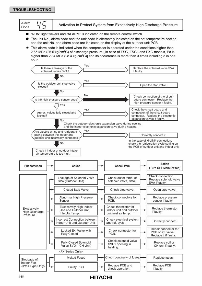
1-64
TROUBLESHOOTING
“RUN” light flickers and “ALARM” is indicated on the remote control switch.
The unit No., alarm code and the unit code is alternately indicated on the set temperature section,and the unit No. and alarm code are indicated on the display of the outdoor unit PCB.
This alarm code is indicated when the compressor is operated under the conditions higher than
2.65 MPa (26.5 kg/cm2G) of discharge pressure [ in case of FSG, FSG1 and FXG models, Pd is
higher than 2.84 MPa (28.4 kg/cm2G)] and its occurrence is more than 3 times including 3 in one
hour.
Alarm
Code
Is the high-pressure sensor good?
Yes
Are ex. valves fully closed andlocked?
Check if indoor or outdoor intakeair temperature is too high.
Check the circuit board andconnection of the circuit boardconnector. Replace the electronicexpansion valves if faulty.
In the case of H-LINK connection,check the refrigeration cycle setting onthe PCB of outdoor unit and indoor unit.
Check connection of the circuitboard connector. Replace thehigh-pressure sensor if faulty.
Open the stop valve.
No
Is there a leakage of thesolenoid valves SVA?
Replace the solenoid valve SVAif faulty.
No
No
Yes
Are electric wiring and refrigerantpiping between the indoor andoutdoor unit incorrectly connected?
Is the outdoor unit stop valveclosed?
No
No
Yes
Yes
Correctly connect it.
Check the outdoor electronic expansion valve during coolingand the indoor electronic expansion valve during heating.
Yes
Activation to Protect System from Excessively High Discharge Pressure
Cause Check ItemAction
(Turn OFF Main Switch)Phenomenon
ExcessivelyHigh DischargePressure
Check stop valve. Open stop valve.Closed Stop Valve
Check outlet temp. ofsolenoid valve, SVA.
Check connection.Replace solenoid valveSVA if faulty.
Leakage of Solenoid ValveSVA (Outdoor Unit)
Check thermistor forindoor unit and outdoorunit inlet air temp.
Replace thermistorif faulty.
Excessively High IndoorUnit and Outdoor UnitInlet Air Temp.
Check connectors forPCB.
Replace pressuresensor if faulty.
Abnormal High PressureSensor
Check electrical systemand ref. cycle. Correctly connect.Incorrect Connection between
Indoor Unit and Outdoor Unit
Check connector forPCB.
<FX Series Only>
Repair connector forPCB or ex. valve.Replace it if faulty.
Locked Ex. Valve withFully Closed
Check solenoid valveSVD1 opening inheating.
Replace coil orCH unit if faulty.
Fully Closed SolenoidValve SVD1 (CH Unit)
Stoppage ofIndoor Fan<Wall Type Only>
Check continuity of fuses. Replace fuses.Melted Fuses
Replace PCB andcheck operation.
Replace PCB if faulty.Faulty PCB
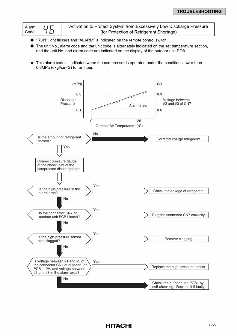
1-65
TROUBLESHOOTING
“RUN” light flickers and “ALARM” is indicated on the remote control switch.
The unit No., alarm code and the unit code is alternately indicated on the set temperature section,
and the unit No. and alarm code are indicated on the display of the outdoor unit PCB.
This alarm code is indicated when the compressor is operated under the conditions lower than
0.6MPa (6kgf/cm2G) for an hour.
Alarm
Code
Activation to Protect System from Excessively Low Discharge Pressure
(for Protection of Refrigerant Shortage)
Is the amount of refrigerantcorrect? Correctly charge refrigerant.
No
0.1
Check the outdoor unit PCB1 byself-checking. Replace it if faulty.
Yes
Is the high-pressure in thealarm area? Check for leakage of refrigerant.
No
Yes
Is the connector CN7 ofoutdoor unit PCB1 loose? Plug the connector CN7 correctly.
No
Yes
Is the high-pressure sensorpipe clogged?
Is voltage between #1 and #3 ofthe connector CN7 of outdoor unitPCB1 12V, and voltage between#2 and #3 in the alarm area?
Remove clogging.
No
No
Yes
Replace the high-pressure sensor.
Yes
Connect pressure gaugeat the check joint of thecompressor discharge pipe.
0.3
0.6
0.9
(MPa) (V)
DischargePressure
Voltage between#2 and #3 of CN7Alarm area
0Outdoor Air Temperature (oC)
26
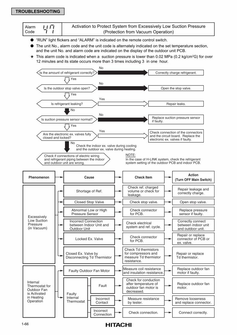
1-66
TROUBLESHOOTING
“RUN” light flickers and “ALARM” is indicated on the remote control switch.
The unit No., alarm code and the unit code is alternately indicated on the set temperature section,
and the unit No. and alarm code are indicated on the display of the outdoor unit PCB.
This alarm code is indicated when a suction pressure is lower than 0.02 MPa (0.2 kg/cm2G) for over
12 minutes and its state occurs more than 3 times including 3 in one hour.
Alarm
Code
Activation to Protect System from Excessively Low Suction Pressure
(Protection from Vacuum Operation)
Is the amount of refrigerant correctly?
Yes
Yes
Is the outdoor stop valve open?
Is refrigerant leaking?
Check if connections of electric wiring and refrigerant piping between the indoor and outdoor unit are wrong.
Check the indoor ex. valve during coolingand the outdoor ex. valve during heating.
Open the stop valve.
Correctly charge refrigerant.
Repair leaks.
No
No
Yes
Is suction pressure sensor normal? Replace suction pressure sensorif faulty.
No
No
Yes
Are the electronic ex. valves fullyclosed and locked?
Check connection of the connectorsand the circuit board. Replace theelectronic ex. valves if faulty.
No
Yes
NOTE:In the case of H-LINK system, check the refrigerantsystem setting of the outdoor PCB and indoor PCB.
Cause Check ItemAction
(Turn OFF Main Switch)Phenomenon
Check for conductionafter temperature ofoutdoor fan motor isdecreased.
FaultyInternalThermostat
Replace outdoor fanmotor.Fault
Measure resistanceby tester.
Remove loosenessand replace connector.
IncorrectContact
Check connection. Connect correctly.IncorrectConnection
ExcessivelyLow SuctionPressure(in Vacuum)
InternalThermostat forOutdoor Fanis Activatedin HeatingOperation
Measure coil resistanceand insulation resistance.
Replace outdoor fanmotor if faulty.Faulty Outdoor Fan Motor
Check ref. chargedvolume or check forleakage.
Repair leakage andcorrectly charge.Shortage of Ref.
Check electricalsystem and ref. cycle.
Correctly connectbetween indoor unitand outdoor unit.
Incorrect Connectionbetween Indoor Unit andOutdoor Unit
Check connectorfor PCB.
Repair or replaceconnector of PCB orex. valve.
Locked Ex. Valve
Check connectorfor PCB.
Replace pressuresensor if faulty.
Abnormal Low or HighPressure Sensor
Check stop valve. Open stop valve.Closed Stop Valve
Check Td thermistors for compressors and measure Td thermistor resistance.
Repair or replaceTd thermistor.
Closed Ex. Valve byDisconnecting Td Thermistor
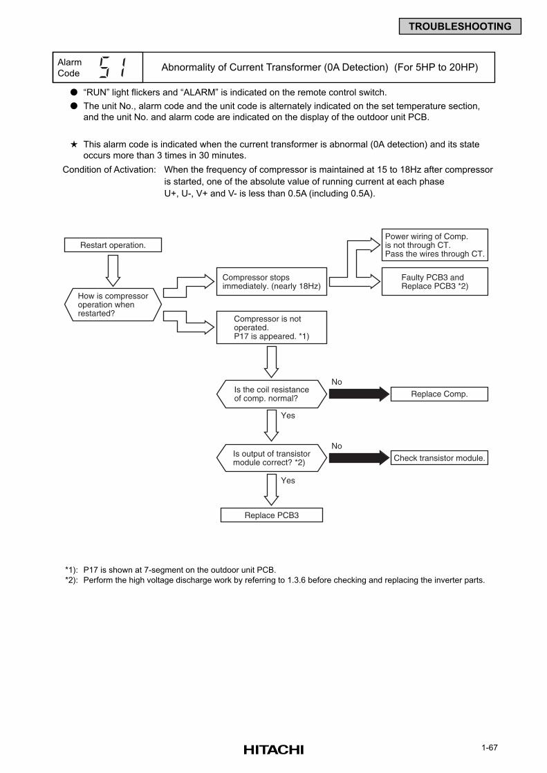
1-67
TROUBLESHOOTING
“RUN” light flickers and “ALARM” is indicated on the remote control switch.
The unit No., alarm code and the unit code is alternately indicated on the set temperature section,
and the unit No. and alarm code are indicated on the display of the outdoor unit PCB.
This alarm code is indicated when the current transformer is abnormal (0A detection) and its state
occurs more than 3 times in 30 minutes.
Condition of Activation: When the frequency of compressor is maintained at 15 to 18Hz after compressor
is started, one of the absolute value of running current at each phase
U+, U-, V+ and V- is less than 0.5A (including 0.5A).
Alarm
CodeAbnormality of Current Transformer (0A Detection) (For 5HP to 20HP)
Replace Comp.
Restart operation.
No
Power wiring of Comp.is not through CT.Pass the wires through CT.
Faulty PCB3 andReplace PCB3 *2)
Compressor stopsimmediately. (nearly 18Hz)
Compressor is notoperated.P17 is appeared. *1)
How is compressoroperation whenrestarted?
Is the coil resistanceof comp. normal?
Yes
Yes
Check transistor module.
Replace PCB3
NoIs output of transistormodule correct? *2)
*1): P17 is shown at 7-segment on the outdoor unit PCB.
*2): Perform the high voltage discharge work by referring to 1.3.6 before checking and replacing the inverter parts.
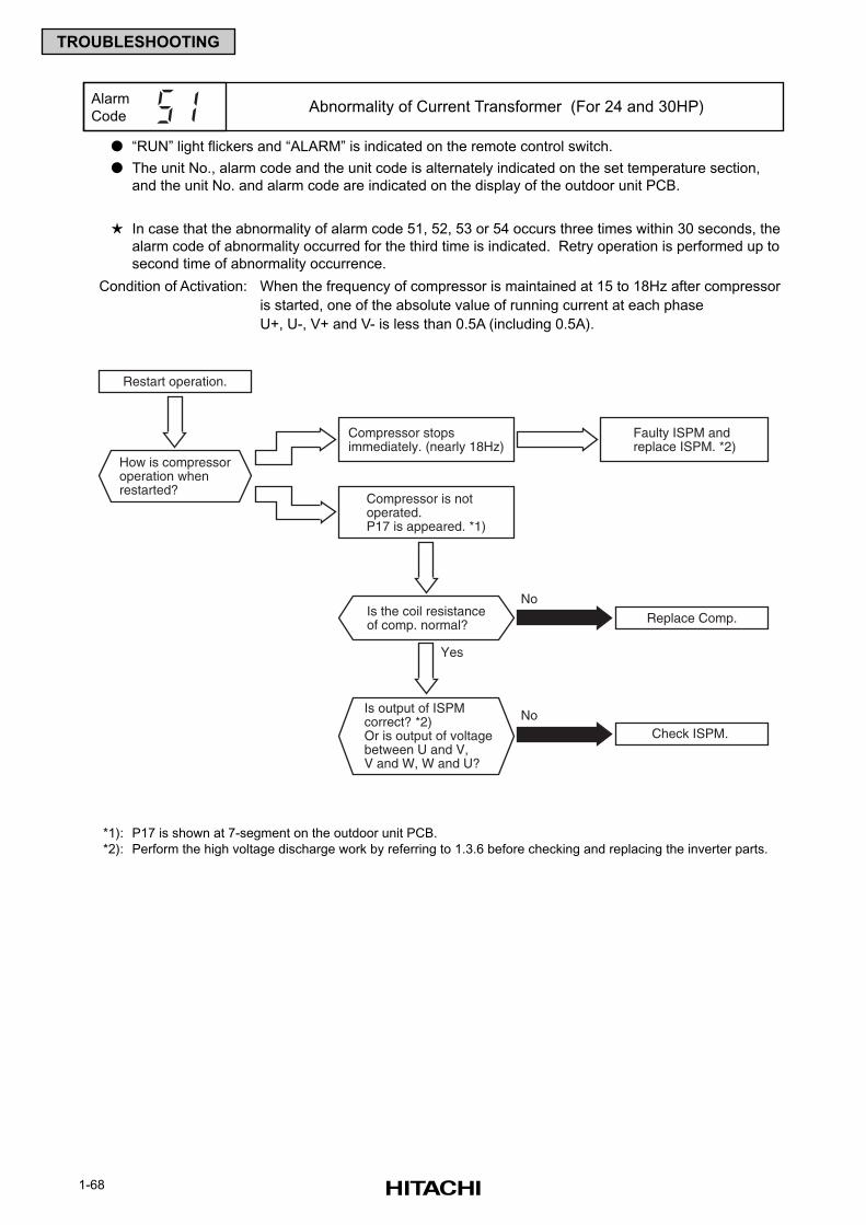
1-68
TROUBLESHOOTING
“RUN” light flickers and “ALARM” is indicated on the remote control switch.
The unit No., alarm code and the unit code is alternately indicated on the set temperature section,
and the unit No. and alarm code are indicated on the display of the outdoor unit PCB.
In case that the abnormality of alarm code 51, 52, 53 or 54 occurs three times within 30 seconds, the
alarm code of abnormality occurred for the third time is indicated. Retry operation is performed up to
second time of abnormality occurrence.
Condition of Activation: When the frequency of compressor is maintained at 15 to 18Hz after compressor
is started, one of the absolute value of running current at each phase
U+, U-, V+ and V- is less than 0.5A (including 0.5A).
Alarm
CodeAbnormality of Current Transformer (For 24 and 30HP)
*1): P17 is shown at 7-segment on the outdoor unit PCB.
*2): Perform the high voltage discharge work by referring to 1.3.6 before checking and replacing the inverter parts.
Replace Comp.
Restart operation.
No
Faulty ISPM andreplace ISPM. *2)
Compressor stopsimmediately. (nearly 18Hz)
Compressor is notoperated.P17 is appeared. *1)
How is compressoroperation whenrestarted?
Is the coil resistanceof comp. normal?
Yes
Check ISPM.NoIs output of ISPM
correct? *2)Or is output of voltagebetween U and V, V and W, W and U?
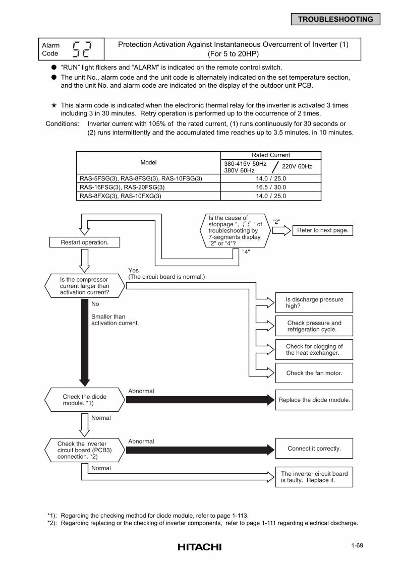
1-69
TROUBLESHOOTING
“RUN” light flickers and “ALARM” is indicated on the remote control switch.
The unit No., alarm code and the unit code is alternately indicated on the set temperature section,
and the unit No. and alarm code are indicated on the display of the outdoor unit PCB.
This alarm code is indicated when the electronic thermal relay for the inverter is activated 3 times
including 3 in 30 minutes. Retry operation is performed up to the occurrence of 2 times.
Conditions: Inverter current with 105% of the rated current, (1) runs continuously for 30 seconds or
(2) runs intermittently and the accumulated time reaches up to 3.5 minutes, in 10 minutes.
*1): Regarding the checking method for diode module, refer to page 1-113.
*2): Regarding replacing or the checking of inverter components, refer to page 1-111 regarding electrical discharge.
Alarm
Code
Protection Activation Against Instantaneous Overcurrent of Inverter (1)
(For 5 to 20HP)
Refer to next page.
Restart operation.
Abnormal
No
Smaller thanactivation current.
Yes(The circuit board is normal.)
Is discharge pressurehigh?
Check pressure andrefrigeration cycle.
Is the compressorcurrent larger thanactivation current?
Check the diodemodule. *1)
Check the invertercircuit board (PCB3)connection. *2)
Normal
Normal
"2"
"4"
Check for clogging ofthe heat exchanger.
Check the fan motor.
Replace the diode module.
AbnormalConnect it correctly.
The inverter circuit boardis faulty. Replace it.
Is the cause ofstoppage " " oftroubleshooting by7-segments display"2" or "4"?
380-415V 50Hz 380V 60Hz
220V 60Hz
RAS-5FSG(3), RAS-8FSG(3), RAS-10FSG(3)
RAS-16FSG(3), RAS-20FSG(3)
RAS-8FXG(3), RAS-10FXG(3)
Model
14.0 / 25.0
16.5 / 30.0
14.0 / 25.0
Rated Current
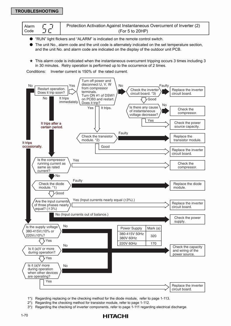
1-70
TROUBLESHOOTING
“RUN” light flickers and “ALARM” is indicated on the remote control switch.
The unit No., alarm code and the unit code is alternately indicated on the set temperature section,
and the unit No. and alarm code are indicated on the display of the outdoor unit PCB.
This alarm code is indicated when the instantaneous overcurrent tripping occurs 3 times including 3
in 30 minutes. Retry operation is performed up to the occurrence of 2 times.
Conditions: Inverter current is 150% of the rated current.
1*): Regarding replacing or the checking method for the diode module, refer to page 1-113.
2*): Regarding the checking method for transistor module, refer to page 1-112.
3*): Regarding the checking of inverter components, refer to page 1-111 regarding electrical discharge.
Alarm
Code
Protection Activation Against Instantaneous Overcurrent of Inverter (2)
(For 5 to 20HP)
Is the compressorrunning current assame as ratedcurrent?
Is it (a)V moreduring operationwhen other devicesare operating?
Check the diodemodule. *1)
Is it (a)V or moreduring operation?
Replace the invertercircuit board.
Replace the invertercircuit board.
Restart operation.Does it trip soon?
Are the input currentsof three phases nearly equal? ( 3%)+_
Replace thetransistor module.
Yes
Yes
Yes
Yes
Yes
Yes
Yes It trips.
No
No
No
No
No
No
No
No
No (Input currents out of balance.)
It tripsimmediately.
Faulty
Faulty
Faulty
Good
Good
Good
Is the supply voltage380-415V±10% or220V±10%?
Check the invertercircuit board. *3)
Check thecompressor.
Check the powersource capacity.
Is there any causeof instantaneousvoltage decrease?
Check the transistormodule. *2)
It tripsoccasionally.It tripsoccasionally.
It trips after acertain period.It trips after acertain period.
Turn off power anddisconnect U, V, Wfrom compressorterminals.Turn ON #1 of DSW1on PCB3 and restart.Does it trip?
Check thecompressor.
Replace the diodemodule.
Replace the invertercircuit board.
Check the powersupply.
Check the capacityand wiring of thepower source.
Replace the invertercircuit board.
Yes (Input currents nearly equal (±3%).)
220V 60Hz
320
170
380-415V 50Hz380V 60Hz
Power Supply Mark (a)
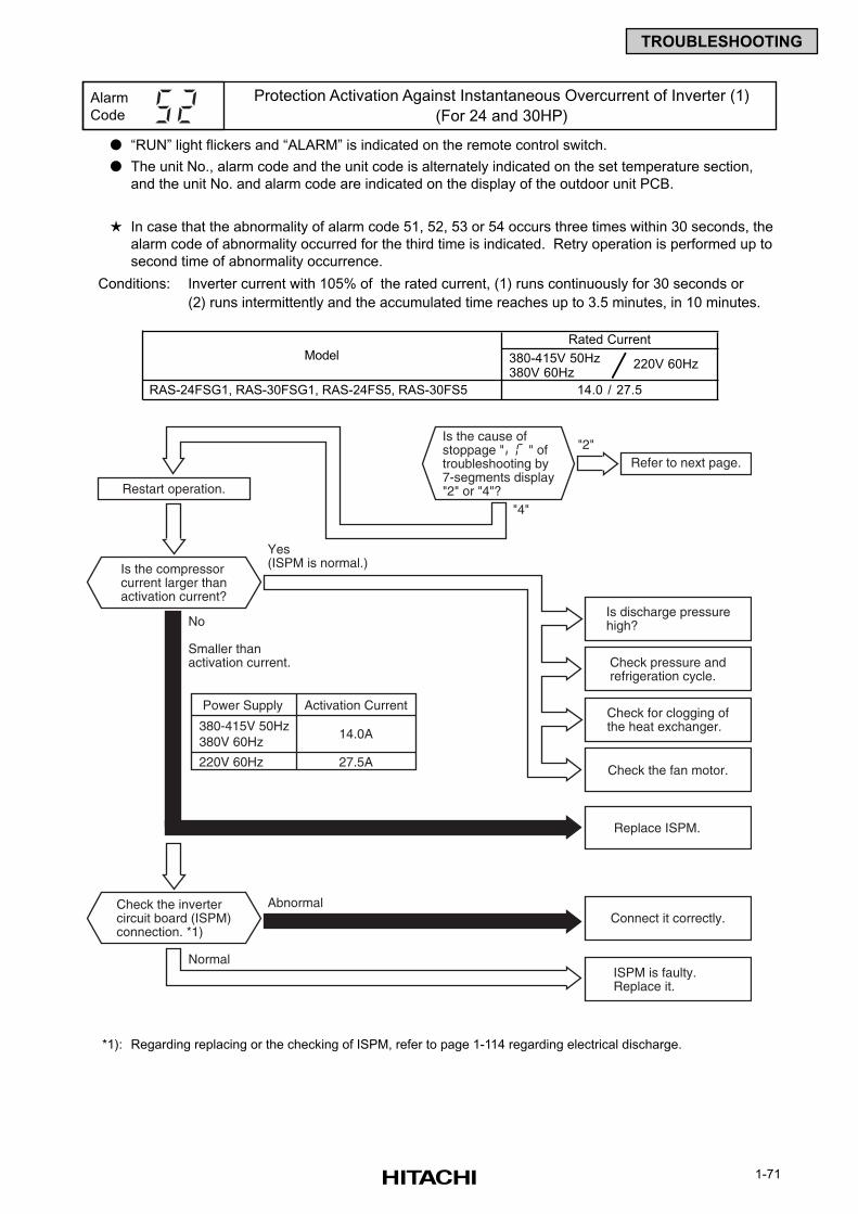
1-71
TROUBLESHOOTING
“RUN” light flickers and “ALARM” is indicated on the remote control switch.
The unit No., alarm code and the unit code is alternately indicated on the set temperature section,
and the unit No. and alarm code are indicated on the display of the outdoor unit PCB.
In case that the abnormality of alarm code 51, 52, 53 or 54 occurs three times within 30 seconds, the
alarm code of abnormality occurred for the third time is indicated. Retry operation is performed up to
second time of abnormality occurrence.
Conditions: Inverter current with 105% of the rated current, (1) runs continuously for 30 seconds or
(2) runs intermittently and the accumulated time reaches up to 3.5 minutes, in 10 minutes.
*1): Regarding replacing or the checking of ISPM, refer to page 1-114 regarding electrical discharge.
Alarm
Code
Protection Activation Against Instantaneous Overcurrent of Inverter (1)
(For 24 and 30HP)
Refer to next page.
Restart operation.
No
Smaller thanactivation current.
Yes(ISPM is normal.)
Is discharge pressurehigh?
Check pressure andrefrigeration cycle.
Is the compressorcurrent larger thanactivation current?
Check the invertercircuit board (ISPM)connection. *1)
Normal
"2"
"4"
Check for clogging ofthe heat exchanger.
Check the fan motor.
Replace ISPM.
AbnormalConnect it correctly.
ISPM is faulty.Replace it.
Is the cause ofstoppage " " oftroubleshooting by7-segments display"2" or "4"?
220V 60Hz
14.0A
27.5A
380-415V 50Hz380V 60Hz
Power Supply Activation Current
380-415V 50Hz 380V 60Hz
220V 60Hz
RAS-24FSG1, RAS-30FSG1, RAS-24FS5, RAS-30FS5
Model
14.0 / 27.5
Rated Current
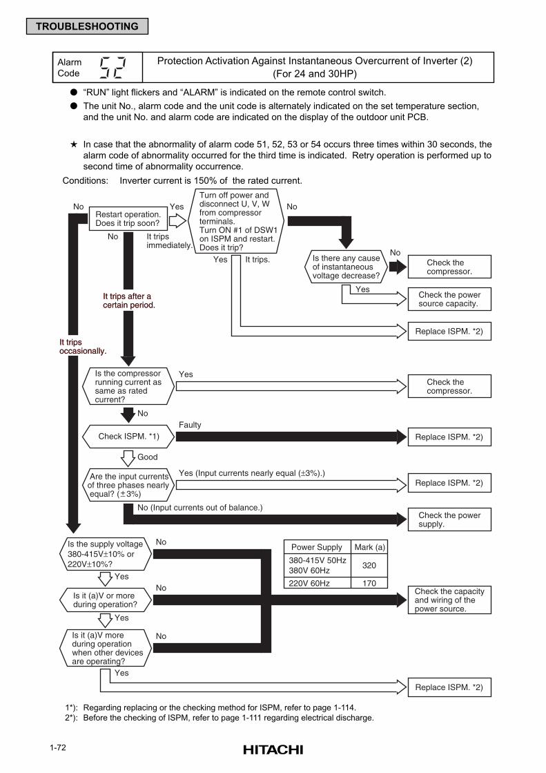
1-72
TROUBLESHOOTING
“RUN” light flickers and “ALARM” is indicated on the remote control switch.
The unit No., alarm code and the unit code is alternately indicated on the set temperature section,
and the unit No. and alarm code are indicated on the display of the outdoor unit PCB.
In case that the abnormality of alarm code 51, 52, 53 or 54 occurs three times within 30 seconds, the
alarm code of abnormality occurred for the third time is indicated. Retry operation is performed up to
second time of abnormality occurrence.
Conditions: Inverter current is 150% of the rated current.
1*): Regarding replacing or the checking method for ISPM, refer to page 1-114.
2*): Before the checking of ISPM, refer to page 1-111 regarding electrical discharge.
Alarm
Code
Protection Activation Against Instantaneous Overcurrent of Inverter (2)
(For 24 and 30HP)
Is the compressorrunning current assame as ratedcurrent?
Check ISPM. *1)
Restart operation.Does it trip soon?
Are the input currentsof three phases nearly equal? ( 3%)+_
Yes
Yes
Yes
Yes It trips.
No
No
No
No
No
No (Input currents out of balance.)
It tripsimmediately.
Faulty
Good
Check thecompressor.
Check the powersource capacity.
Is there any causeof instantaneousvoltage decrease?
It tripsoccasionally.It tripsoccasionally.
It trips after acertain period.It trips after acertain period.
Turn off power anddisconnect U, V, Wfrom compressorterminals.Turn ON #1 of DSW1on ISPM and restart.Does it trip?
Check thecompressor.
Replace ISPM. *2)
Replace ISPM. *2)
Replace ISPM. *2)
Replace ISPM. *2)
Check the powersupply.
Yes (Input currents nearly equal (±3%).)
Is it (a)V moreduring operationwhen other devicesare operating?
Is it (a)V or moreduring operation?
Yes
Yes
Yes
No
No
No
Is the supply voltage380-415V±10% or220V±10%?
Check the capacityand wiring of thepower source.
220V 60Hz
320
170
380-415V 50Hz380V 60Hz
Power Supply Mark (a)
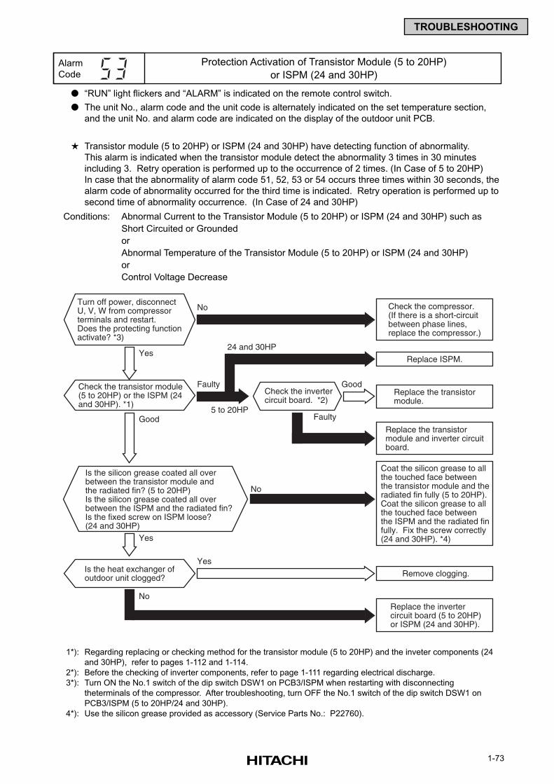
1-73
TROUBLESHOOTING
Yes
Yes
Faulty
Faulty
Check the invertercircuit board. *2)
Turn off power, disconnectU, V, W from compressorterminals and restart. Does the protecting functionactivate? *3)
Check the transistor module(5 to 20HP) or the ISPM (24and 30HP). *1)
Good
Good
No
Is the heat exchanger ofoutdoor unit clogged?
No Check the compressor.(If there is a short-circuitbetween phase lines,replace the compressor.)
Replace the transistormodule and inverter circuitboard.
Replace the transistormodule.
Replace the invertercircuit board (5 to 20HP)or ISPM (24 and 30HP).
Remove clogging.
Replace ISPM.
5 to 20HP
24 and 30HP
Yes
Is the silicon grease coated all overbetween the transistor module andthe radiated fin? (5 to 20HP)Is the silicon grease coated all overbetween the ISPM and the radiated fin?Is the fixed screw on ISPM loose?(24 and 30HP)
No
Coat the silicon grease to allthe touched face betweenthe transistor module and theradiated fin fully (5 to 20HP).Coat the silicon grease to allthe touched face betweenthe ISPM and the radiated finfully. Fix the screw correctly(24 and 30HP). *4)
“RUN” light flickers and “ALARM” is indicated on the remote control switch.
The unit No., alarm code and the unit code is alternately indicated on the set temperature section,
and the unit No. and alarm code are indicated on the display of the outdoor unit PCB.
Transistor module (5 to 20HP) or ISPM (24 and 30HP) have detecting function of abnormality.
This alarm is indicated when the transistor module detect the abnormality 3 times in 30 minutes
including 3. Retry operation is performed up to the occurrence of 2 times. (In Case of 5 to 20HP)
In case that the abnormality of alarm code 51, 52, 53 or 54 occurs three times within 30 seconds, the
alarm code of abnormality occurred for the third time is indicated. Retry operation is performed up to
second time of abnormality occurrence. (In Case of 24 and 30HP)
Conditions: Abnormal Current to the Transistor Module (5 to 20HP) or ISPM (24 and 30HP) such as
Short Circuited or Grounded
or
Abnormal Temperature of the Transistor Module (5 to 20HP) or ISPM (24 and 30HP)
or
Control Voltage Decrease
1*): Regarding replacing or checking method for the transistor module (5 to 20HP) and the inveter components (24
and 30HP), refer to pages 1-112 and 1-114.
2*): Before the checking of inverter components, refer to page 1-111 regarding electrical discharge.
3*): Turn ON the No.1 switch of the dip switch DSW1 on PCB3/ISPM when restarting with disconnecting
theterminals of the compressor. After troubleshooting, turn OFF the No.1 switch of the dip switch DSW1 on
PCB3/ISPM (5 to 20HP/24 and 30HP).
4*): Use the silicon grease provided as accessory (Service Parts No.: P22760).
Alarm
Code
Protection Activation of Transistor Module (5 to 20HP)
or ISPM (24 and 30HP)
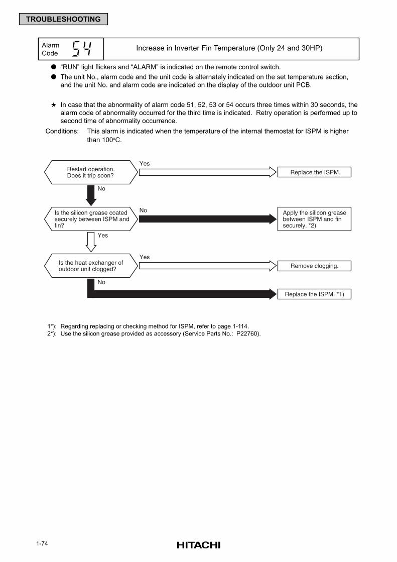
1-74
TROUBLESHOOTING
“RUN” light flickers and “ALARM” is indicated on the remote control switch.
The unit No., alarm code and the unit code is alternately indicated on the set temperature section,
and the unit No. and alarm code are indicated on the display of the outdoor unit PCB.
In case that the abnormality of alarm code 51, 52, 53 or 54 occurs three times within 30 seconds, the
alarm code of abnormality occurred for the third time is indicated. Retry operation is performed up to
second time of abnormality occurrence.
Conditions: This alarm is indicated when the temperature of the internal themostat for ISPM is higher
than 100oC.
1*): Regarding replacing or checking method for ISPM, refer to page 1-114.
2*): Use the silicon grease provided as accessory (Service Parts No.: P22760).
Alarm
CodeIncrease in Inverter Fin Temperature (Only 24 and 30HP)
Yes
No
Restart operation.Does it trip soon?
Is the heat exchanger ofoutdoor unit clogged?
No
Apply the silicon greasebetween ISPM and finsecurely. *2)
Replace the ISPM.
Replace the ISPM. *1)
Remove clogging.
Yes
Yes
No
Is the silicon grease coatedsecurely between ISPM andfin?
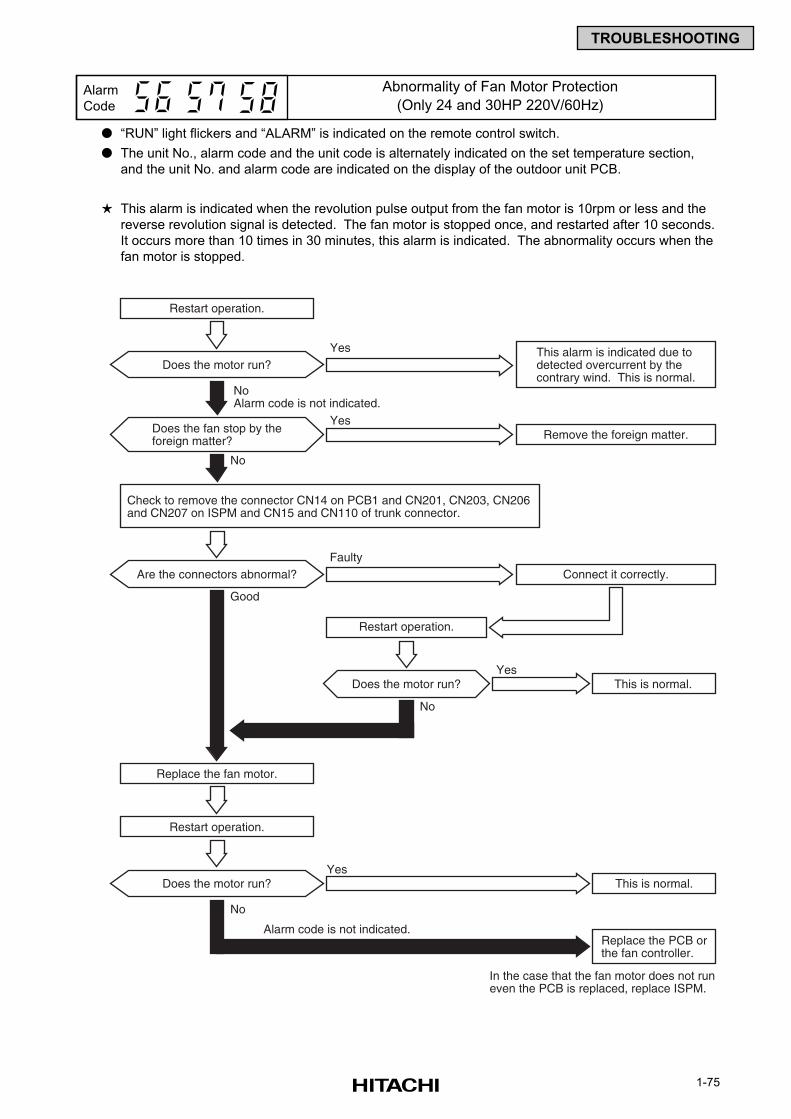
1-75
TROUBLESHOOTING
“RUN” light flickers and “ALARM” is indicated on the remote control switch.
The unit No., alarm code and the unit code is alternately indicated on the set temperature section,
and the unit No. and alarm code are indicated on the display of the outdoor unit PCB.
This alarm is indicated when the revolution pulse output from the fan motor is 10rpm or less and the
reverse revolution signal is detected. The fan motor is stopped once, and restarted after 10 seconds.
It occurs more than 10 times in 30 minutes, this alarm is indicated. The abnormality occurs when the
fan motor is stopped.
Alarm
Code
Abnormality of Fan Motor Protection
(Only 24 and 30HP 220V/60Hz)
Are the connectors abnormal?
Good
Replace the fan motor.
In the case that the fan motor does not runeven the PCB is replaced, replace ISPM.
Remove the foreign matter.
Does the motor run?This alarm is indicated due to detected overcurrent by the contrary wind. This is normal.
NoAlarm code is not indicated.
Yes
Does the fan stop by theforeign matter?
No
Yes
Connect it correctly.Faulty
Restart operation.
Check to remove the connector CN14 on PCB1 and CN201, CN203, CN206and CN207 on ISPM and CN15 and CN110 of trunk connector.
No
This is normal.Yes
Alarm code is not indicated.
This is normal.Yes
Replace the PCB orthe fan controller.
No
Does the motor run?
Restart operation.
Does the motor run?
Restart operation.
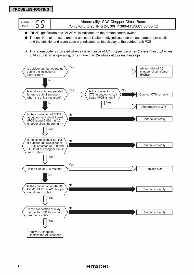
1-76
TROUBLESHOOTING
“RUN” light flickers and “ALARM” is indicated on the remote control switch.
The unit No., alarm code and the unit code is alternately indicated on the set temperature section,
and the unit No. and alarm code are indicated on the display of the outdoor unit PCB.
This alarm code is indicated when a current value of AC chopper becomes (1) less than 0.5A when
outdoor unit fan is operating, or (2) more than 2A while outdoor unit fan stops.
Alarm
Code
Abnormality of AC Chopper Circuit Board
(Only for 5 to 20HP & 24, 30HP 380-415/380V 50/60Hz)
Yes
Yes
Yes
No
No
No
Is the connection ofCT5 at outdoor circuitboard (PCB1) right?
Is outdoor unit fan operatingduring the indication ofalarm code?
Is the connection of CN13at outdoor unit circuit board(PCB1) and CN201 at ACchopper circuit board right?
No
Abnormality of ACchopper circuit board(PCB2).
Yes
Connect CT5 correctly.
Connect correctly.
Yes
Is the connection of S3, R3at outdoor unit circuit board(PCB1) or faston of EF9 andS1, R1 at AC chopper circuitboard right?
Connect correctly.
No
Connect correctly.
No
Connect correctly.
Faulty AC chopper.Replace the AC chopper.
Replace fuse.
Abnormality of CT5.
Yes
Is the fuse of EF9 melted?
Yes
Is outdoor unit fan operatedfor more than 2 secondswhen the unit is restarted?
Is the connection of MAIN1,COM1, SUB1 at AC choppercircuit board right?
Yes
Is the connection of relayconnector CN1 for outdoorfan motor right?
No
No
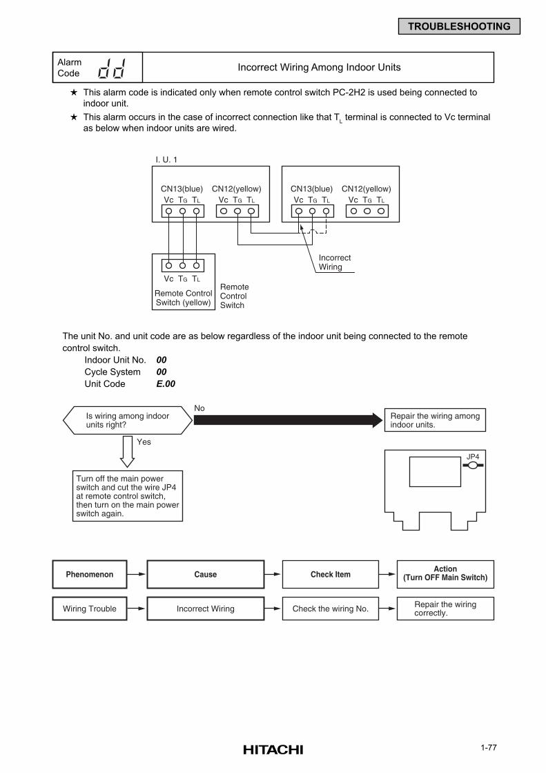
1-77
TROUBLESHOOTING
This alarm code is indicated only when remote control switch PC-2H2 is used being connected to
indoor unit.
This alarm occurs in the case of incorrect connection like that TL terminal is connected to Vc terminal
as below when indoor units are wired.
The unit No. and unit code are as below regardless of the indoor unit being connected to the remote
control switch.
Indoor Unit No. 00
Cycle System 00
Unit Code E.00
Alarm
CodeIncorrect Wiring Among Indoor Units
Yes
Is wiring among indoorunits right?
No
JP4
Repair the wiring amongindoor units.
Turn off the main powerswitch and cut the wire JP4at remote control switch,then turn on the main powerswitch again.
Cause Check ItemAction
(Turn OFF Main Switch)Phenomenon
Wiring Trouble Check the wiring No. Repair the wiringcorrectly.Incorrect Wiring
CN13(blue)Vc TG TL
CN12(yellow)Vc TG TL
I. U. 1
CN13(blue)Vc TG TL
CN12(yellow)Vc TG TL
Vc TG TL
Remote ControlSwitch (yellow)
Remote ControlSwitch
IncorrectWiring
1-78
TROUBLESHOOTING
This alarm code appears when one of the following alarms occurs three times within 6 hours, which
may result in serious compressor damages, if the outdoor unit is continuously operated without
removing the cause.
Alarm Code: Content of Abnormality
02 Tripping of Protection Device in Outdoor Unit
07 Decrease in Discharge Gas Superheat
08 Increase in Discharge Gas Temperature
39 Abnormality of Running Current at Constant Comp.
43 Pressure Ratio Decrease Protection Activating
44 Low Pressure Increase Protection Activating
45 High Pressure Increase Protection Activating
46 High Pressure Decrease Protection Activating
47 Low Pressure Decrease Protection Activating
These alarms are able to be checked by the CHECK Mode 1. Follow the action indicated in each
alarm chart.
These alarms are cleared only by turning OFF the main power switch to the system. However,
careful attention is required before starting, since there is a possibility which will result in
serious damages to the compressors.
Alarm
CodeCompressor Protection
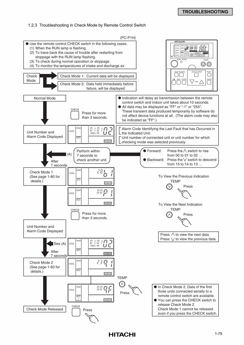
1-79
TROUBLESHOOTING
1.2.3 Troubleshooting in Check Mode by Remote Control Switch
Check Mode 1: Current data will be displayed.
Check Mode 2: Data held immediately beforefailure, will be displayed.
CheckMode
Normal Mode
(PC-P1H)
Check Mode Released
Use the remote control CHECK switch in the following cases.(1) When the RUN lamp is flashing.(2) To trace back the cause of trouble after restarting from
stoppage with the RUN lamp flashing.(3) To check during normal operation or stoppage.(4) To monitor the temperatures of intake and discharge air.
Forward: Press the switch to risefrom 00 to 01 to 02 …
Backward: Press the switch to descendfrom 15 to 14 to 13 …
Indication will delay as transmission between the remotecontrol switch and indoor unit takes about 10 seconds.
All data may be displayed as "FF" or "-1" or "255".These transient data produced temporarily by software donot affect device functions at all. (The alarm code may alsobe indicated as "FF".)
In Check Mode 2, Data of the firstthree units connected serially to aremote control switch are available.
You can press the CHECK switch torelease Check Mode 2.Check Mode 1 cannot be releasedeven if you press the CHECK switch.
Alarm Code Identifying the Last Fault that has Occurred inthe Indicated Unit.Unit number of connected unit or unit number for whichchecking mode was selected previously.
Unit Number andAlarm Code Displayed
After7 seconds
Perform within7 seconds tocheck another unit.
(A)
Press for morethan 3 seconds.
To View the Previous IndicationTEMP
Press
CHECK
Press for morethan 3 seconds.
CHECK
PressCHECK
Unit Number andAlarm Code Displayed
Check Mode 1(See page 1-80 for details.)
Press to view the next data.Press to view the previous data.
Check Mode 2(See page 1-83 for details.)
COOL
HIGH
A/C
ADDS. RN
CHECK
COOL
HIGH
A/C
CHECK
COOL
HIGH
A/C
CHECK
COOL
HIGH
A/C
CHECK
COOL
HIGH
+VENTI
A/C
CHECK
COOL
HIGH
A/C
ADDS. RN
CHECKCHECKAfter7 seconds
See (A)
To View the Next IndicationTEMP
Press
TEMP
Press
TEMP.RUN / STOP
MODE FAN SPEED
VENTI
RESET
CHECKLOUVER
ON/OFF TIMER
TIME
NO FUNCTION
FAN
COOL
HEAT
DRY
AUTO
HIGH
MED
LOW
A/C
VENT+
SWING
DEFROSTCENTRALH.STRG
SERVICE
ON/OFF TIMER SET TEMP.
RN HR
FILTER
T. RUN
ABNML
CHECK
ADDS
UNIT
LOUVER
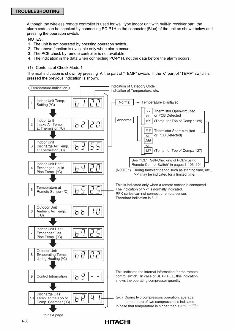
1-80
TROUBLESHOOTING
Although the wireless remote controller is used for wall type indoor unit with built-in receiver part, the
alarm code can be checked by connecting PC-P1H to the connector (Blue) of the unit as shown below and
pressing the operation switch.
NOTES:
1. The unit is not operated by pressing operation switch.
2. The above function is available only when alarm occurs.
3. The PCB check by remote controller is not available.
4. The indication is the data when connecting PC-P1H, not the data before the alarm occurs.
(1) Contents of Check Mode 1
The next indication is shown by pressing the part of “TEMP” switch. If the part of “TEMP” switch is
pressed the previous indication is shown.
Temperature Indication
Normal
Thermistor Open-circuitedor PCB Defected
(Temp. for Top of Comp.: 129)
……Temperature Displayed
Abnormal
Indication of Category CodeIndication of Temperature, etc.
1 Indoor Unit Temp.Setting (oC)
Indoor UnitIntake Air Temp.at Thermistor (oC)
2
Indoor UnitDischarge Air Temp.at Thermistor (oC)
3
Indoor Unit HeatExchanger LiquidPipe Temp. (oC)
4
Temperature atRemote Sensor (oC)5
Outdoor UnitAmbient Air Temp. (oC)
6
Indoor Unit HeatExchanger GasPipe Temp. (oC)
7
Outdoor UnitEvaporating Temp.during Heating (oC)
8
Control Information9
Discharge GasTemp. at the Top ofComp. Chamber (oC)
10
See "1.3.1 Self-Checking of PCB's usingRemote Control Switch" in pages 1-103, 104.
(NOTE 1) During transient period such as starting time, etc.,"- -" may be indicated for a limited time.
This is indicated only when a remote sensor is connected.The indication of "- -" is normally indicated.RPK series can not connect a remote sensor.Therefore indication is "- -".
to next page
- -or
129
Thermistor Short-circuitedor PCB Defected)
F For
255
(Temp. for Top of Comp.: 127)or
127
This indicates the internal information for the remotecontrol switch. In case of SET-FREE, this indicationshows the operating compressor quantity.
(ex.) During two compressors operation, averagetemperature of two compressors is indicated.
In case that temperature is higher than 126oC, " ".
>
>
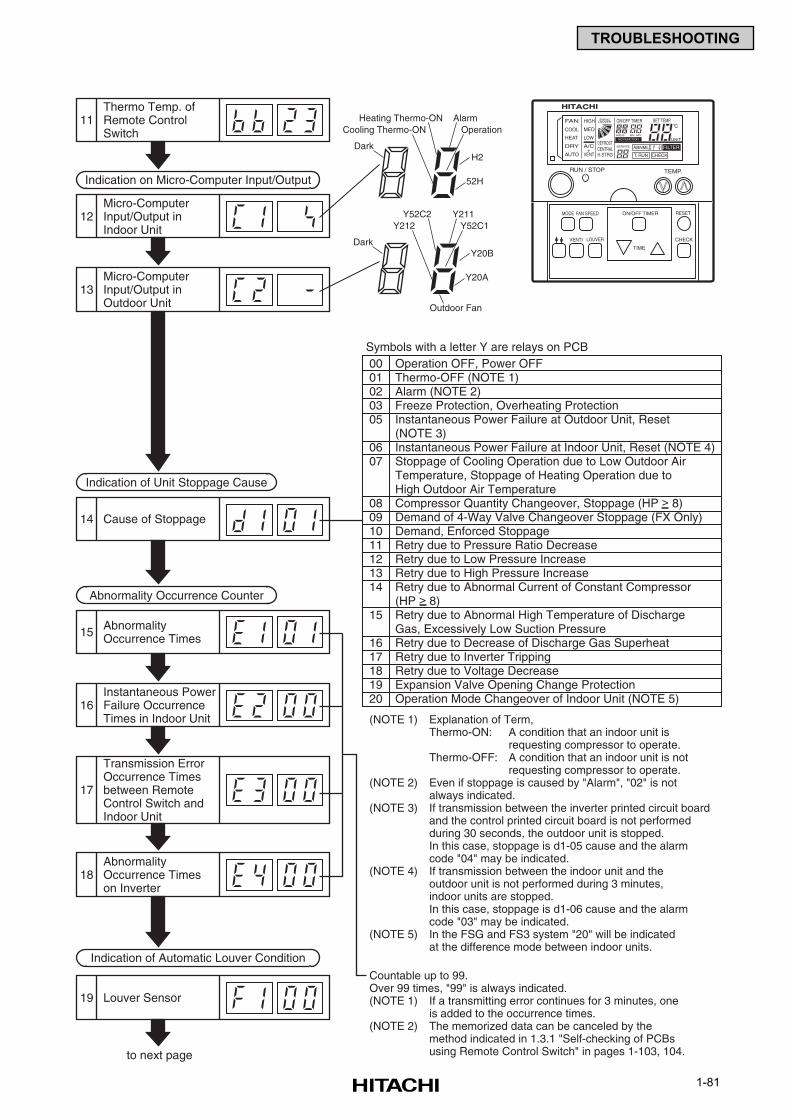
1-81
TROUBLESHOOTING
Indication on Micro-Computer Input/Output
Thermo Temp. ofRemote ControlSwitch
11
Micro-ComputerInput/Output inOutdoor Unit
13
Cause of Stoppage14
AbnormalityOccurrence Times15
Instantaneous PowerFailure OccurrenceTimes in Indoor Unit
16
AbnormalityOccurrence Timeson Inverter
18
Transmission ErrorOccurrence Timesbetween RemoteControl Switch andIndoor Unit
17
Louver Sensor19
Micro-ComputerInput/Output inIndoor Unit
12
Heating Thermo-ONCooling Thermo-ON
Dark
AlarmOperation
H2
52H
to next page
Countable up to 99.Over 99 times, "99" is always indicated.(NOTE 1) If a transmitting error continues for 3 minutes, one
is added to the occurrence times.(NOTE 2) The memorized data can be canceled by the
method indicated in 1.3.1 "Self-checking of PCBsusing Remote Control Switch" in pages 1-103, 104.
Symbols with a letter Y are relays on PCB00 Operation OFF, Power OFF01 Thermo-OFF (NOTE 1)02 Alarm (NOTE 2)03 Freeze Protection, Overheating Protection05 Instantaneous Power Failure at Outdoor Unit, Reset
(NOTE 3)06 Instantaneous Power Failure at Indoor Unit, Reset (NOTE 4)07 Stoppage of Cooling Operation due to Low Outdoor Air
Temperature, Stoppage of Heating Operation due toHigh Outdoor Air Temperature
08 Compressor Quantity Changeover, Stoppage (HP > 8)09 Demand of 4-Way Valve Changeover Stoppage (FX Only)10 Demand, Enforced Stoppage11 Retry due to Pressure Ratio Decrease12 Retry due to Low Pressure Increase13 Retry due to High Pressure Increase14 Retry due to Abnormal Current of Constant Compressor
(HP > 8)15 Retry due to Abnormal High Temperature of Discharge
Gas, Excessively Low Suction Pressure16 Retry due to Decrease of Discharge Gas Superheat17 Retry due to Inverter Tripping18 Retry due to Voltage Decrease19 Expansion Valve Opening Change Protection20 Operation Mode Changeover of Indoor Unit (NOTE 5)
(NOTE 1) Explanation of Term,Thermo-ON: A condition that an indoor unit is
requesting compressor to operate.Thermo-OFF: A condition that an indoor unit is not
requesting compressor to operate.(NOTE 2) Even if stoppage is caused by "Alarm", "02" is not
always indicated.(NOTE 3) If transmission between the inverter printed circuit board
and the control printed circuit board is not performed during 30 seconds, the outdoor unit is stopped.In this case, stoppage is d1-05 cause and the alarmcode "04" may be indicated.
(NOTE 4) If transmission between the indoor unit and theoutdoor unit is not performed during 3 minutes,indoor units are stopped.In this case, stoppage is d1-06 cause and the alarmcode "03" may be indicated.
(NOTE 5) In the FSG and FS3 system "20" will be indicatedat the difference mode between indoor units.
Indication of Unit Stoppage Cause
Abnormality Occurrence Counter
Indication of Automatic Louver Condition
Y52C2Y212
Dark
Y211Y52C1
Y20B
Y20A
Outdoor Fan
TEMP.RUN / STOP
MODE FAN SPEED
VENTI
RESET
CHECKLOUVER
ON/OFF TIMER
TIME
NO FUNCTION
FAN
COOL
HEAT
DRY
AUTO
HIGH
MED
LOW
A/C
VENT+
SWING
DEFROSTCENTRALH.STRG
SERVICE
ON/OFF TIMER SET TEMP.
RN HR
FILTER
T. RUN
ABNML
CHECK
ADDS
UNIT
LOUVER
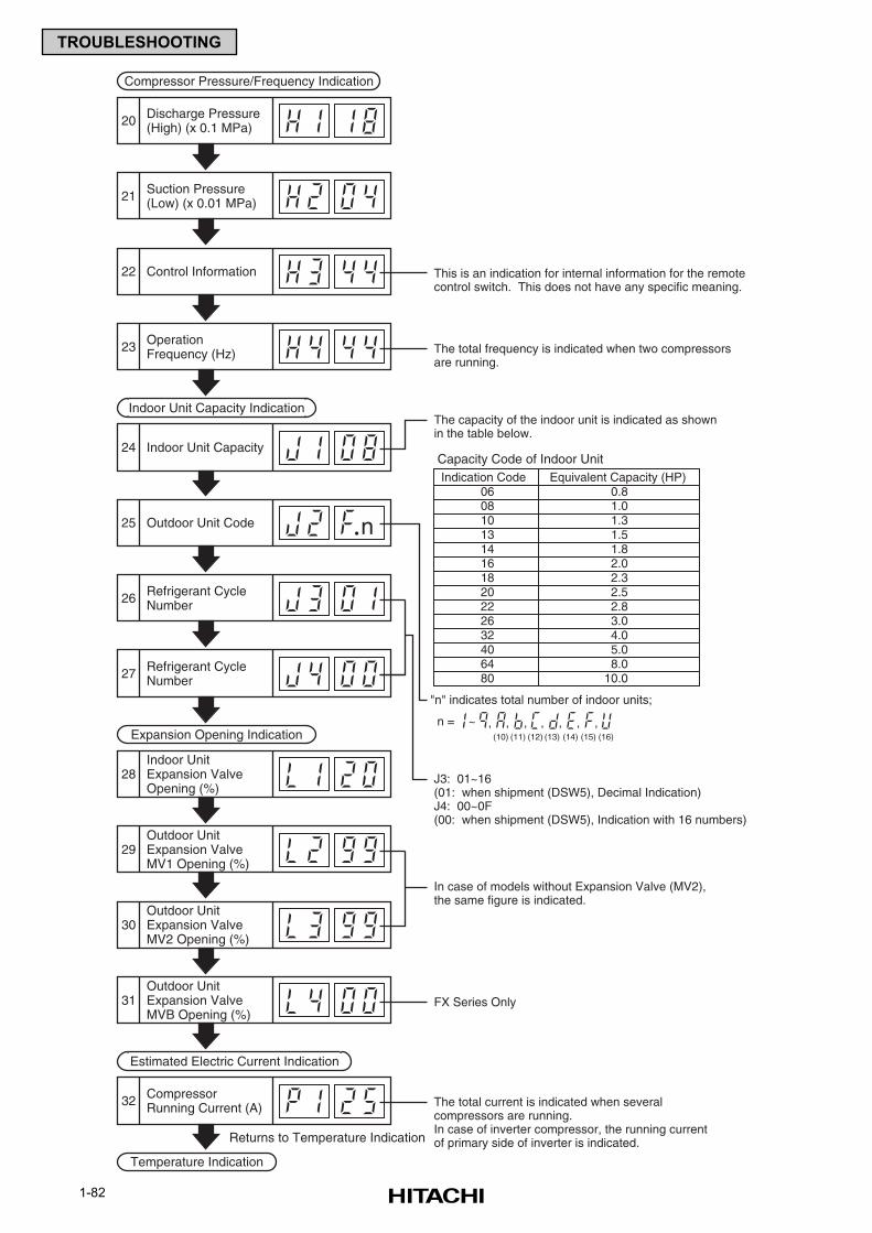
1-82
TROUBLESHOOTING
Compressor Pressure/Frequency Indication
Discharge Pressure(High) (x 0.1 MPa)20
Suction Pressure(Low) (x 0.01 MPa)21
Control Information22
OperationFrequency (Hz)23
Outdoor Unit Code25
Refrigerant CycleNumber26
Refrigerant CycleNumber27
Indoor Unit Capacity24
The total current is indicated when severalcompressors are running.In case of inverter compressor, the running currentof primary side of inverter is indicated.
Capacity Code of Indoor Unit
06 0.808 1.010 1.313 1.514 1.816 2.018 2.320 2.522 2.826 3.032 4.040 5.064 8.080 10.0
Indication Code Equivalent Capacity (HP)
J3: 01~16 (01: when shipment (DSW5), Decimal Indication)J4: 00~0F(00: when shipment (DSW5), Indication with 16 numbers)
In case of models without Expansion Valve (MV2),the same figure is indicated.
FX Series Only
This is an indication for internal information for the remotecontrol switch. This does not have any specific meaning.
The total frequency is indicated when two compressorsare running.
The capacity of the indoor unit is indicated as shownin the table below.
n
Indoor Unit Capacity Indication
Outdoor UnitExpansion ValveMV1 Opening (%)
29
Outdoor UnitExpansion ValveMV2 Opening (%)
30
Outdoor UnitExpansion ValveMVB Opening (%)
31
Indoor UnitExpansion ValveOpening (%)
28
Expansion Opening Indication
CompressorRunning Current (A)32
Estimated Electric Current Indication
Temperature Indication
Returns to Temperature Indication
"n" indicates total number of indoor units;
n = ~ , , , , , , ,(10) (11) (12) (13) (14) (15) (16)
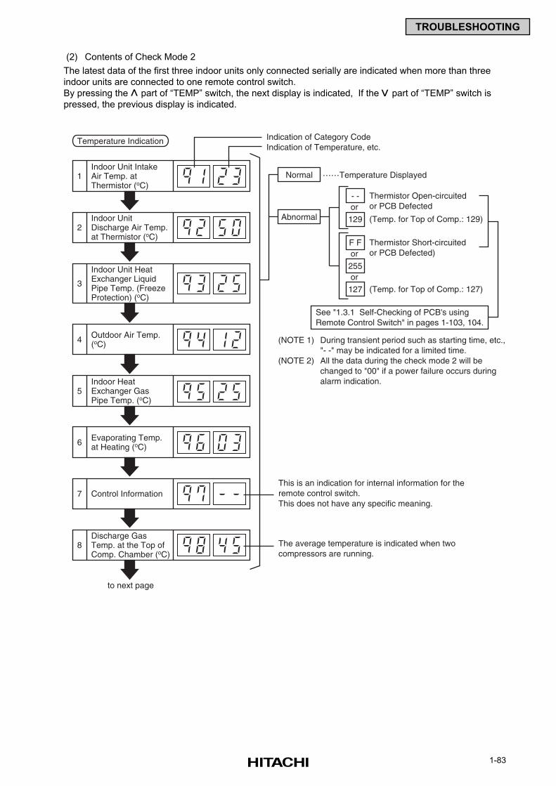
1-83
TROUBLESHOOTING
Temperature Indication
Normal
Thermistor Open-circuitedor PCB Defected
(Temp. for Top of Comp.: 129)
……Temperature Displayed
Abnormal
Indication of Category CodeIndication of Temperature, etc.
1Indoor Unit IntakeAir Temp. atThermistor (oC)
Indoor UnitDischarge Air Temp.at Thermistor (oC)
2
Indoor Unit HeatExchanger LiquidPipe Temp. (FreezeProtection) (oC)
3
Outdoor Air Temp.(oC)4
Indoor HeatExchanger GasPipe Temp. (oC)
5
Evaporating Temp.at Heating (oC)6
Control Information7
Discharge GasTemp. at the Top ofComp. Chamber (oC)
8
See "1.3.1 Self-Checking of PCB's usingRemote Control Switch" in pages 1-103, 104.
(NOTE 1) During transient period such as starting time, etc.,"- -" may be indicated for a limited time.
(NOTE 2) All the data during the check mode 2 will bechanged to "00" if a power failure occurs duringalarm indication.
to next page
- -or
129
Thermistor Short-circuitedor PCB Defected)
F For
255
(Temp. for Top of Comp.: 127)or
127
This is an indication for internal information for theremote control switch.This does not have any specific meaning.
The average temperature is indicated when twocompressors are running.
(2) Contents of Check Mode 2
The latest data of the first three indoor units only connected serially are indicated when more than three
indoor units are connected to one remote control switch.
By pressing the part of “TEMP” switch, the next display is indicated, If the part of “TEMP” switch is
pressed, the previous display is indicated.
>
>
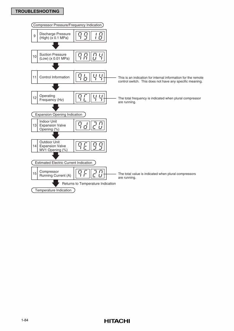
1-84
TROUBLESHOOTING
Compressor Pressure/Frequency Indication
Discharge Pressure(High) (x 0.1 MPa)9
Suction Pressure(Low) (x 0.01 MPa)10
Control Information11
OperatingFrequency (Hz)12
The total value is indicated when plural compressorsare running.
This is an indication for internal information for the remotecontrol switch. This does not have any specific meaning.
The total frequency is indicated when plural compressorare running.
Outdoor UnitExpansion ValveMV1 Opening (%)
14
Indoor UnitExpansion ValveOpening (%)
13
Expansion Opening Indication
CompressorRunning Current (A)15
Estimated Electric Current Indication
Temperature Indication
Returns to Temperature Indication
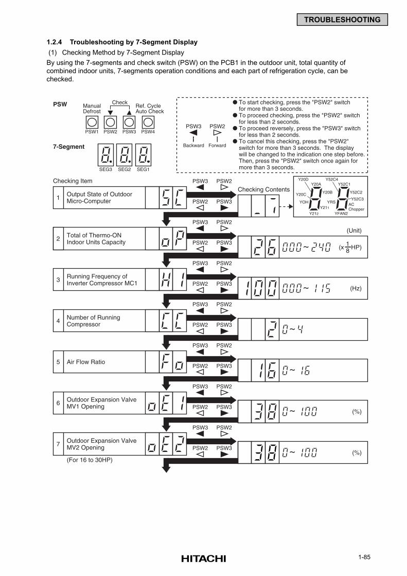
1-85
TROUBLESHOOTING
1.2.4 Troubleshooting by 7-Segment Display
(1) Checking Method by 7-Segment Display
By using the 7-segments and check switch (PSW) on the PCB1 in the outdoor unit, total quantity of
combined indoor units, 7-segments operation conditions and each part of refrigeration cycle, can be
checked.
Output State of OutdoorMicro-Computer
Checking Item
PSW
7-Segment
~
PSW3
SEG3
PSW2 Y20DY20A
Y20CY52C3
Y212
Y211
YOH
Y20B
1
PSW3 PSW2
To start checking, press the "PSW2" switchfor more than 3 seconds.
To proceed checking, press the "PSW2" switchfor less than 2 seconds.
To proceed reversely, press the "PSW3" switchfor less than 2 seconds.
To cancel this checking, press the "PSW2"switch for more than 3 seconds. The displaywill be changed to the indication one step before.Then, press the "PSW2" switch once again formore than 3 seconds.
Backward Forward
PSW2 PSW3
Total of Thermo-ONIndoor Units Capacity
PSW3 PSW2
2PSW2 PSW3
Running Frequency ofInverter Compressor MC1
Checking Contents
(Unit)
(Hz)
PSW3 PSW2
3PSW2 PSW3
Number of RunningCompressor
PSW3 PSW2
4
~PSW2 PSW3
1(x HP)8
~
(%)~
~
(%)~
Air Flow Ratio
PSW3 PSW2
5PSW2 PSW3
Outdoor Expansion ValveMV1 Opening
PSW3 PSW2
6PSW2 PSW3
Outdoor Expansion ValveMV2 Opening
PSW3 PSW2
7PSW2 PSW3
(For 16 to 30HP)
Y52C4Y52C1
YFAN2
ACChopper
YRS
Y52C2
SEG2 SEG1
PSW4
CheckManualDefrost
Ref. CycleAuto Check
PSW3PSW2PSW1
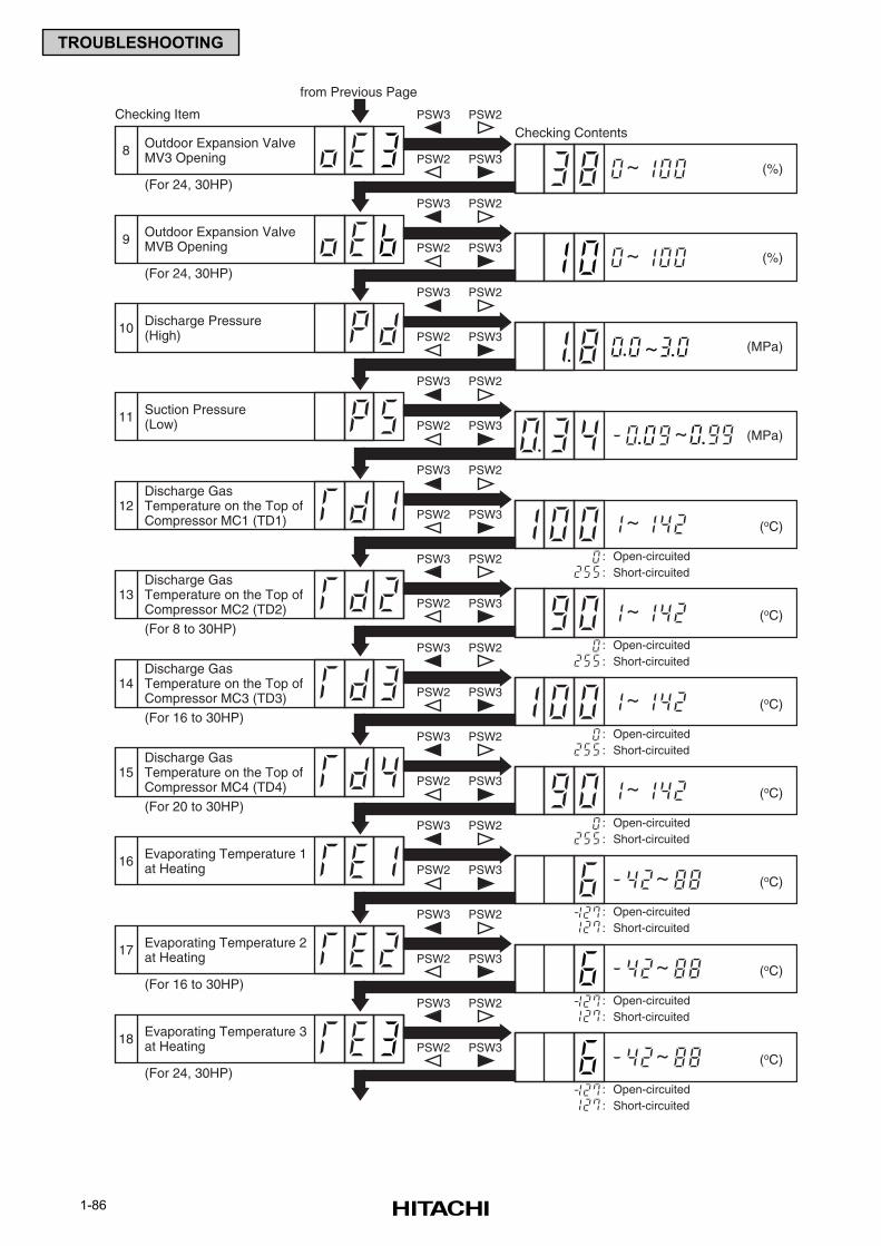
1-86
TROUBLESHOOTING
Discharge Pressure(High)
Checking Item
from Previous Page
~
~
PSW3 PSW2
10PSW2 PSW3
Suction Pressure(Low)
PSW3 PSW2
11PSW2 PSW3
Discharge GasTemperature on the Top ofCompressor MC1 (TD1)
Checking Contents
(MPa)
(MPa)
PSW3 PSW2
12
Discharge GasTemperature on the Top ofCompressor MC2 (TD2)
13
PSW2 PSW3
: Open-circuited: Short-circuited
PSW3 PSW2
PSW2 PSW3
~
PSW3 PSW2
PSW2 PSW3
PSW3 PSW2
(oC)~
: Open-circuited: Short-circuited
(oC)~
: Open-circuited: Short-circuited
(oC)~
: Open-circuited: Short-circuited
(oC)~
(oC)
: Open-circuited: Short-circuited
~ (oC)
: Open-circuited: Short-circuited
~ (oC)
: Open-circuited: Short-circuited
PSW2 PSW3
PSW3 PSW2
PSW2 PSW3
(For 8 to 30HP)
(For 24, 30HP)
(For 24, 30HP)
PSW3 PSW2
PSW2 PSW3
Discharge GasTemperature on the Top ofCompressor MC3 (TD3)
14
(For 16 to 30HP)
Discharge GasTemperature on the Top ofCompressor MC4 (TD4)
15
Evaporating Temperature 1at Heating16
Evaporating Temperature 2at Heating17
PSW3 PSW2
PSW2 PSW3
(For 16 to 30HP)
Evaporating Temperature 3at Heating18
(For 24, 30HP)
(For 20 to 30HP)
(%)~
(%)~
Outdoor Expansion ValveMV3 Opening
PSW3 PSW2
8PSW2 PSW3
Outdoor Expansion ValveMVB Opening
PSW3 PSW2
9PSW2 PSW3
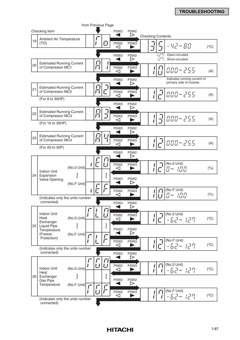
1-87
TROUBLESHOOTING
Estimated Running Currentof Compressor MC3
Checking Item
from Previous Page
PSW3 PSW2
22PSW2 PSW3
PSW3 PSW2
23PSW2 PSW3
Indoor UnitExpansionValve Opening
(No.0 Unit)
(No.F Unit)
~~
Checking Contents
PSW3 PSW2
PSW3 PSW2
PSW3 PSW2
24
PSW2 PSW3
PSW3 PSW2
PSW2 PSW3
(oC)
(A)~
(A)
(No.0 Unit)
(%)~(No.F Unit)
(%)~(No.0 Unit)
~
~
(oC)(No.F Unit)
~
(For 16 to 30HP)
Estimated Running Currentof Compressor MC4
(For 20 to 30P)
(Indicates only the units number connected)
Indoor UnitHeatExchangerLiquid PipeTemperature(Freeze Protection)
(No.0 Unit)
(No.F Unit)
~~25
PSW2 PSW3
PSW3 PSW2
PSW2 PSW3
(Indicates only the units number connected)
(oC)(No.0 Unit)
~
(oC)(No.F Unit)
~
Indoor UnitHeatExchangerGas PipeTemperature
(No.0 Unit)
(No.F Unit)
~~26
PSW2 PSW3
PSW3 PSW2
PSW2 PSW3
(Indicates only the units number connected)
(A)~
~ (A)
~ (oC)
: Open-circuited: Short-circuited
Indicates running current ofprimary side of inverter.
(For 8 to 30HP)
Ambient Air Temperature(TO)19
PSW3 PSW2
PSW2 PSW3
Estimated Running Currentof Compressor MC120
PSW3 PSW2
PSW2 PSW3
PSW3 PSW2
PSW2 PSW3Estimated Running Currentof Compressor MC221
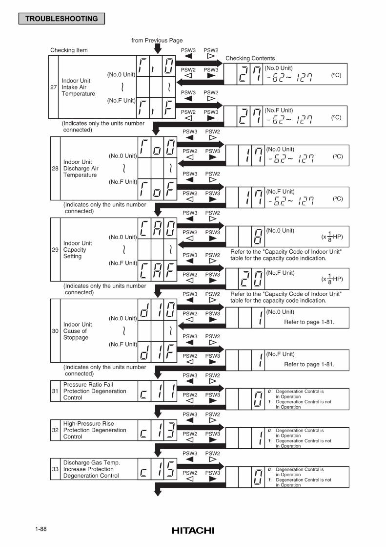
1-88
TROUBLESHOOTING
Checking Item
from Previous Page
Indoor UnitDischarge AirTemperature
(No.0 Unit)
(No.F Unit)
~~
Checking Contents
PSW3 PSW2
28
PSW2 PSW3
PSW3 PSW2
PSW2 PSW3
(oC)(No.0 Unit)
(No.F Unit)
(No.0 Unit)
~
(oC)(No.F Unit)
~(Indicates only the units number connected)
Refer to the "Capacity Code of Indoor Unit"table for the capacity code indication.
Refer to the "Capacity Code of Indoor Unit"table for the capacity code indication.
Indoor UnitCapacitySetting
(No.0 Unit)
(No.F Unit)
~~
PSW3 PSW2
29
PSW2 PSW3
PSW3 PSW2
PSW2 PSW3
(Indicates only the units number connected)
(No.F Unit)
0: Degeneration Control isin Operation
1: Degeneration Control is notin Operation
(No.0 Unit)
Refer to page 1-81.Indoor UnitCause ofStoppage
(No.0 Unit)
(No.F Unit)
~~
PSW3 PSW2
30
PSW2 PSW3
PSW3 PSW2
PSW2 PSW3
(Indicates only the units number connected)
Pressure Ratio FallProtection DegenerationControl
PSW3 PSW2
31PSW2 PSW3
0: Degeneration Control isin Operation
1: Degeneration Control is notin Operation
High-Pressure RiseProtection DegenerationControl
PSW3 PSW2
32PSW2 PSW3
0: Degeneration Control isin Operation
1: Degeneration Control is notin Operation
Discharge Gas Temp.Increase ProtectionDegeneration Control
PSW3 PSW2
33PSW2 PSW3
1(x HP)8
1(x HP)8
PSW3 PSW2
(oC)(No.0 Unit)
~
(oC)(No.F Unit)
~
Indoor UnitIntake AirTemperature
(No.0 Unit)
(No.F Unit)
~~27
PSW2 PSW3
PSW3 PSW2
PSW2 PSW3
(Indicates only the units number connected)
Refer to page 1-81.
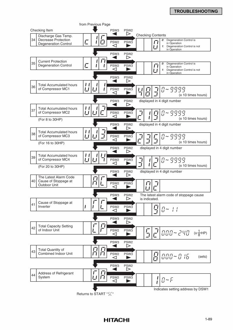
1-89
TROUBLESHOOTING
Checking Item
from Previous Page
Checking Contents
~(x 10 times hours)
Current ProtectionDegeneration Control
PSW3 PSW2
35PSW2 PSW3
0: Degeneration Control isin Operation
1: Degeneration Control is notin Operation
Total Accumulated hoursof Compressor MC1
PSW3 PSW2
36PSW2 PSW3
~(x 10 times hours)
Total Accumulated hoursof Compressor MC2
PSW3 PSW2
37PSW2 PSW3
~(x 10 times hours)
Total Accumulated hoursof Compressor MC3
PSW3 PSW2
38PSW2 PSW3
~(x 10 times hours)
Total Accumulated hoursof Compressor MC4
PSW3 PSW2
39PSW2 PSW3
The Latest Alarm CodeCause of Stoppage atOutdoor Unit
PSW3 PSW2
40PSW2 PSW3
Cause of Stoppage atInverter
PSW3 PSW2
41PSW2 PSW3
Total Capacity Settingof Indoor Unit
PSW3 PSW2
42PSW2 PSW3
Total Quantity ofCombined Indoor Unit
PSW3 PSW2
43PSW2 PSW3
Address of RefrigerantSystem
PSW3 PSW2
44PSW2 PSW3
~
(sets)
~
1(x HP)8
~
~
(For 8 to 30HP)
(For 16 to 30HP)
(For 20 to 30HP)
displayed in 4 digit number
displayed in 4 digit number
displayed in 4 digit number
displayed in 4 digit number
The latest alarm code of stoppage causeis indicated.
Indicates setting address by DSW1Returns to START " "
0: Degeneration Control isin Operation
1: Degeneration Control is notin Operation
Discharge Gas Temp.Decrease ProtectionDegeneration Control
PSW3 PSW2
34PSW2 PSW3
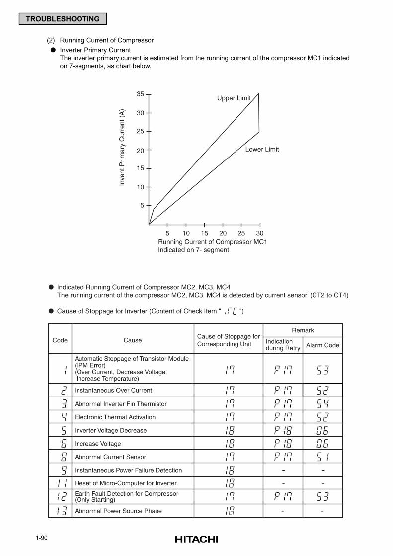
1-90
TROUBLESHOOTING
Upper Limit
Lower Limit
Inve
nt P
rimar
y C
urre
nt (
A)
35
30
25
20
15
10
5
30252015105Running Current of Compressor MC1Indicated on 7- segment
(2) Running Current of Compressor
Inverter Primary Current
The inverter primary current is estimated from the running current of the compressor MC1 indicated
on 7-segments, as chart below.
RemarkCause of Stoppage forCorresponding Unit
Automatic Stoppage of Transistor Module(IPM Error)(Over Current, Decrease Voltage, Increase Temperature)
Instantaneous Over Current
Electronic Thermal Activation
Inverter Voltage Decrease
Increase Voltage
Abnormal Current Sensor
Instantaneous Power Failure Detection
Reset of Micro-Computer for Inverter
Code CauseAlarm Code
Indicationduring Retry
Abnormal Inverter Fin Thermistor
Earth Fault Detection for Compressor(Only Starting)
Abnormal Power Source Phase
Indicated Running Current of Compressor MC2, MC3, MC4The running current of the compressor MC2, MC3, MC4 is detected by current sensor. (CT2 to CT4)
Cause of Stoppage for Inverter (Content of Check Item " ")
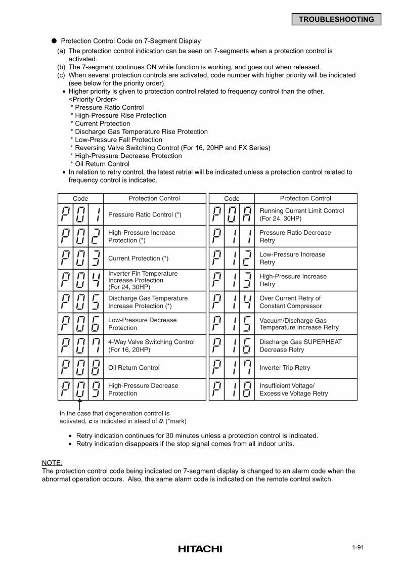
1-91
TROUBLESHOOTING
Protection Control Code on 7-Segment Display
(a) The protection control indication can be seen on 7-segments when a protection control is
activated.
(b) The 7-segment continues ON while function is working, and goes out when released.
(c) When several protection controls are activated, code number with higher priority will be indicated
(see below for the priority order).
• Higher priority is given to protection control related to frequency control than the other.
<Priority Order>
* Pressure Ratio Control
* High-Pressure Rise Protection
* Current Protection
* Discharge Gas Temperature Rise Protection
* Low-Pressure Fall Protection
* Reversing Valve Switching Control (For 16, 20HP and FX Series)
* High-Pressure Decrease Protection
* Oil Return Control
• In relation to retry control, the latest retrial will be indicated unless a protection control related to
frequency control is indicated.
• Retry indication continues for 30 minutes unless a protection control is indicated.
• Retry indication disappears if the stop signal comes from all indoor units.
NOTE:
The protection control code being indicated on 7-segment display is changed to an alarm code when the
abnormal operation occurs. Also, the same alarm code is indicated on the remote control switch.
Protection Control
Pressure Ratio Control (*)
Code Protection Control
Pressure Ratio DecreaseRetry
Code
Running Current Limit Control(For 24, 30HP)
High-Pressure IncreaseProtection (*)
Low-Pressure IncreaseRetry
Current Protection (*)
High-Pressure IncreaseRetry
Discharge Gas TemperatureIncrease Protection (*)
Inverter Fin TemperatureIncrease Protection(For 24, 30HP)
Over Current Retry ofConstant Compressor
Low-Pressure DecreaseProtection
Vacuum/Discharge GasTemperature Increase Retry
4-Way Valve Switching Control(For 16, 20HP)
Discharge Gas SUPERHEATDecrease Retry
Oil Return Control Inverter Trip Retry
High-Pressure DecreaseProtection
In the case that degeneration control isactivated, c is indicated in stead of 0. (*mark)
Insufficient Voltage/Excessive Voltage Retry
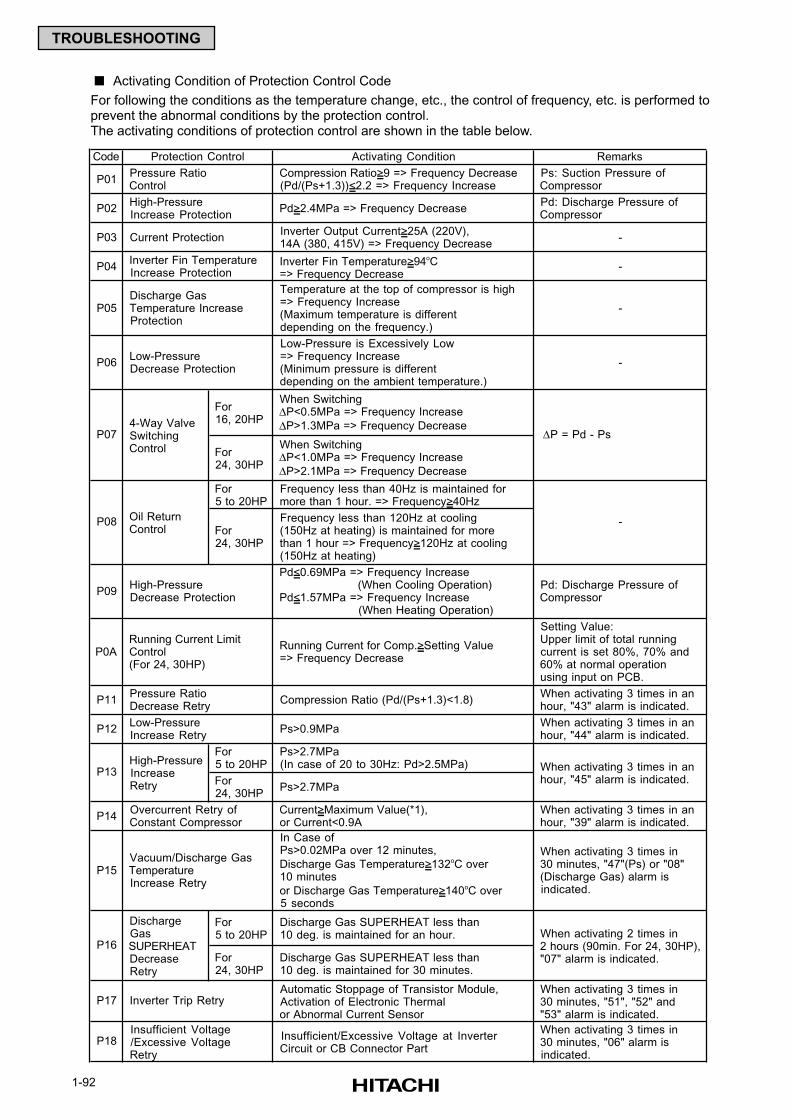
1-92
TROUBLESHOOTING
Activating Condition of Protection Control Code
For following the conditions as the temperature change, etc., the control of frequency, etc. is performed toprevent the abnormal conditions by the protection control.The activating conditions of protection control are shown in the table below.
Code Activating Condition Remarks
P01 Compression Ratio>9 => Frequency Decrease (Pd/(Ps+1.3))<2.2 => Frequency Increase
Ps: Suction Pressure of Compressor
P02 Pd>2.4MPa => Frequency Decrease Pd: Discharge Pressure of Compressor
P03 Inverter Output Current>25A (220V), 14A (380, 415V) => Frequency Decrease
-
P04 Inverter Fin Temperature>94oC => Frequency Decrease
-
P05
Temperature at the top of compressor is high => Frequency Increase (Maximum temperature is different depending on the frequency.)
-
P06
Low-Pressure is Excessively Low => Frequency Increase (Minimum pressure is different depending on the ambient temperature.)
-
For 16, 20HP
When Switching ∆P<0.5MPa => Frequency Increase
∆P>1.3MPa => Frequency Decrease
For 24, 30HP
When Switching ∆P<1.0MPa => Frequency Increase
∆P>2.1MPa => Frequency Decrease
For 5 to 20HP
Frequency less than 40Hz is maintained for more than 1 hour. => Frequency>40Hz
For 24, 30HP
Frequency less than 120Hz at cooling (150Hz at heating) is maintained for more than 1 hour => Frequency>120Hz at cooling (150Hz at heating)
P09
Pd<0.69MPa => Frequency Increase (When Cooling Operation) Pd<1.57MPa => Frequency Increase (When Heating Operation)
Pd: Discharge Pressure of Compressor
P0A Running Current for Comp.>Setting Value => Frequency Decrease
Setting Value: Upper limit of total running current is set 80%, 70% and 60% at normal operation using input on PCB.
P11 Compression Ratio (Pd/(Ps+1.3)<1.8) When activating 3 times in an hour, "43" alarm is indicated.
P12 Ps>0.9MPa When activating 3 times in an hour, "44" alarm is indicated.
For 5 to 20HP
Ps>2.7MPa (In case of 20 to 30Hz: Pd>2.5MPa)
For 24, 30HP
Ps>2.7MPa
P14 Current>Maximum Value(*1), or Current<0.9A
When activating 3 times in an hour, "39" alarm is indicated.
P15
In Case of Ps>0.02MPa over 12 minutes,
Discharge Gas Temperature>132oC over 10 minutes
or Discharge Gas Temperature>140oC over 5 seconds
When activating 3 times in 30 minutes, "47"(Ps) or "08" (Discharge Gas) alarm is indicated.
For 5 to 20HP
Discharge Gas SUPERHEAT less than 10 deg. is maintained for an hour.
For 24, 30HP
Discharge Gas SUPERHEAT less than 10 deg. is maintained for 30 minutes.
P17 Inverter Trip Retry Automatic Stoppage of Transistor Module, Activation of Electronic Thermal or Abnormal Current Sensor
When activating 3 times in 30 minutes, "51", "52" and "53" alarm is indicated.
P18 Insufficient/Excessive Voltage at Inverter Circuit or CB Connector Part
When activating 3 times in 30 minutes, "06" alarm is indicated.
P13
∆P = Pd - Ps
-
P16
4-Way Valve Switching Control
Discharge Gas SUPERHEAT Decrease Retry
When activating 3 times in an hour, "45" alarm is indicated.
When activating 2 times in 2 hours (90min. For 24, 30HP), "07" alarm is indicated.
Protection Control
P07
P08
Vacuum/Discharge Gas Temperature Increase Retry
Pressure Ratio Control
High-Pressure Increase Protection
Current Protection
Inverter Fin Temperature Increase Protection
Discharge Gas Temperature Increase Protection
Low-Pressure Decrease Protection
Insufficient Voltage /Excessive Voltage Retry
Oil Return Control
Running Current Limit Control (For 24, 30HP)
Pressure Ratio Decrease Retry
Low-Pressure Increase Retry
Overcurrent Retry of Constant Compressor
High-Pressure Increase Retry
High-Pressure Decrease Protection
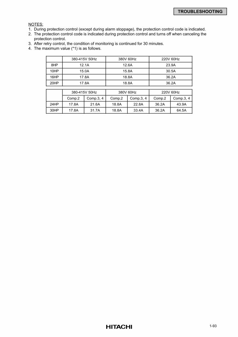
1-93
TROUBLESHOOTING
NOTES:
1. During protection control (except during alarm stoppage), the protection control code is indicated.
2. The protection control code is indicated during protection control and turns off when canceling the
protection control.
3. After retry control, the condition of monitoring is continued for 30 minutes.
4. The maximum value (*1) is as follows.
8HP
10HP
16HP
20HP
Comp.2 Comp.3, 4 Comp.2 Comp.3, 4 Comp.2 Comp.3, 4
24HP 17.8A 21.6A 18.8A 22.8A 36.2A 43.9A
30HP 17.8A 31.7A 18.8A 33.4A 36.2A 64.5A
23.9A
30.5A
36.2A
36.2A
12.6A
15.8A
18.8A
18.8A
380-415V 50Hz 380V 60Hz 220V 60Hz
380-415V 50Hz 380V 60Hz 220V 60Hz
12.1A
15.0A
17.8A
17.8A
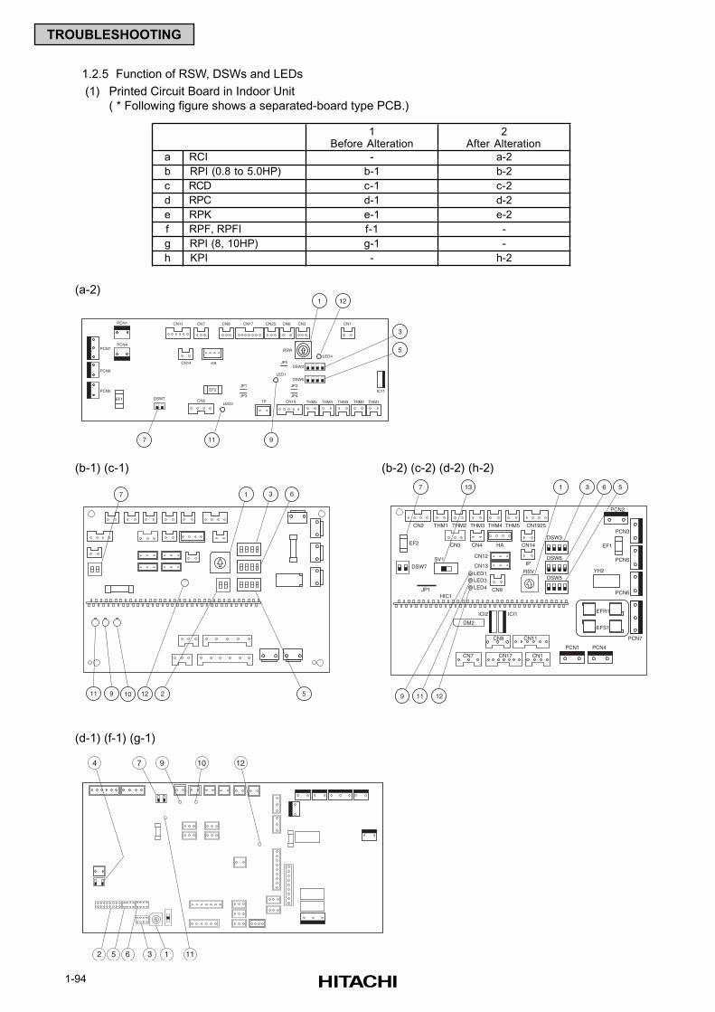
1-94
TROUBLESHOOTING
1.2.5 Function of RSW, DSWs and LEDs
(1) Printed Circuit Board in Indoor Unit
( * Following figure shows a separated-board type PCB.)
PCN7
PCN6
PCN5
PCN1
PCN4
EF1
EF2
CN11
CN14
CN8CN7 CN17 CN25 CN6 CN3 CN1
RSW
LED4
LED1
LED3 THM1THM2THM3THM4THM5CN19CN2 TP
JP1
JP5
JP3
JP2
JP4
HA
IC11
DSW3
DSW5
DSW7
7 9
3
1
5
11
12
2 512911 10
7 1 3 6
EF2 EF1
7
9 11 12
13
CN2 THM1 THM2 THM3 THM4 THM5 CN1925
CN3 CN4 CN14
IP
HA
RSV
CN12
CN13
CN9
LED1LED3LED4
DSW7SV1
DSW3
DSW6
DSW5
PCN2
PCN3
PCN5
PCN6
PCN7
PCN1 PCN4
YH2
EFR1
EFS1
ICI1ICI2
DM2
CN8 CN11
CN1CN17CN7
1 3 6 5
JP1HIC1
4 7 9 10 12
2 5 6 3 1 11
1Before Alteration
2After Alteration
a RCI - a-2
b RPI (0.8 to 5.0HP) b-1 b-2
c RCD c-1 c-2
d RPC d-1 d-2
e RPK e-1 e-2
f RPF, RPFI f-1 -
g RPI (8, 10HP) g-1 -
h KPI - h-2
(a-2)
(b-1) (c-1) (b-2) (c-2) (d-2) (h-2)
(d-1) (f-1) (g-1)
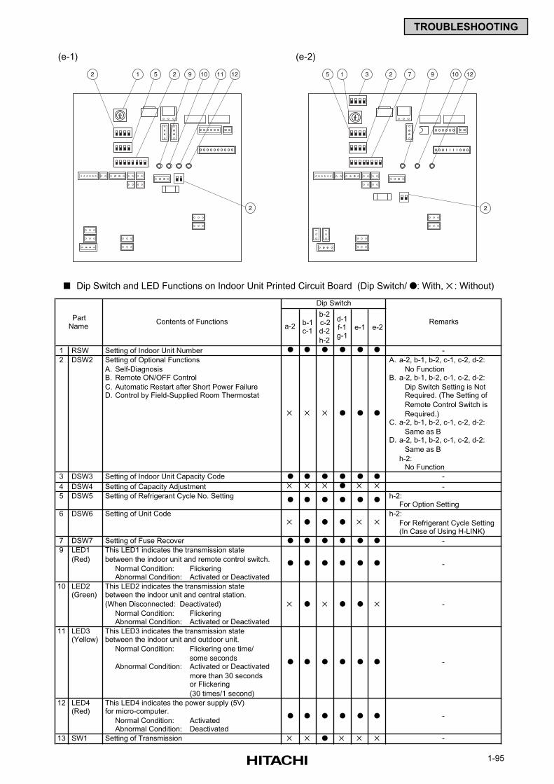
1-95
TROUBLESHOOTING
Dip Switch and LED Functions on Indoor Unit Printed Circuit Board (Dip Switch/ : With, : Without)
2
2
1 5 2 9 10 11 12 5 1 3 2 7 9 10 12
2
(e-1) (e-2)
a-2b-1c-1
b-2c-2d-2
h-2
d-1f-1g-1
e-1 e-2
1 RSW Setting of Indoor Unit Number
2 DSW2 Setting of Optional Functions A. a-2, b-1, b-2, c-1, c-2, d-2:
A. Self-Diagnosis No Function B. Remote ON/OFF Control B. a-2, b-1, b-2, c-1, c-2, d-2:
C. Automatic Restart after Short Power Failure Dip Switch Setting is Not D. Control by Field-Supplied Room Thermostat Required. (The Setting of
Remote Control Switch is Required.)
C. a-2, b-1, b-2, c-1, c-2, d-2:
Same as B D. a-2, b-1, b-2, c-1, c-2, d-2:
Same as B
h-2:No Function
3 DSW3 Setting of Indoor Unit Capacity Code
4 DSW4 Setting of Capacity Adjustment
5 DSW5 Setting of Refrigerant Cycle No. Setting h-2:For Option Setting
6 DSW6 Setting of Unit Code h-2: For Refrigerant Cycle Setting
(In Case of Using H-LINK)
7 DSW7 Setting of Fuse Recover
9 LED1 This LED1 indicates the transmission state
(Red) between the indoor unit and remote control switch.
Normal Condition: FlickeringAbnormal Condition: Activated or Deactivated
10 LED2 This LED2 indicates the transmission state (Green) between the indoor unit and central station.
(When Disconnected: Deactivated)
Normal Condition: FlickeringAbnormal Condition: Activated or Deactivated
11 LED3 This LED3 indicates the transmission state (Yellow) between the indoor unit and outdoor unit.
Normal Condition: Flickering one time/
some secondsAbnormal Condition: Activated or Deactivated
more than 30 secondsor Flickering
(30 times/1 second)
12 LED4 This LED4 indicates the power supply (5V) (Red) for micro-computer.
Normal Condition: ActivatedAbnormal Condition: Deactivated
13 SW1 Setting of Transmission
-
-
RemarksContents of Functions
-
Dip Switch
PartName
-
-
-
-
-
-
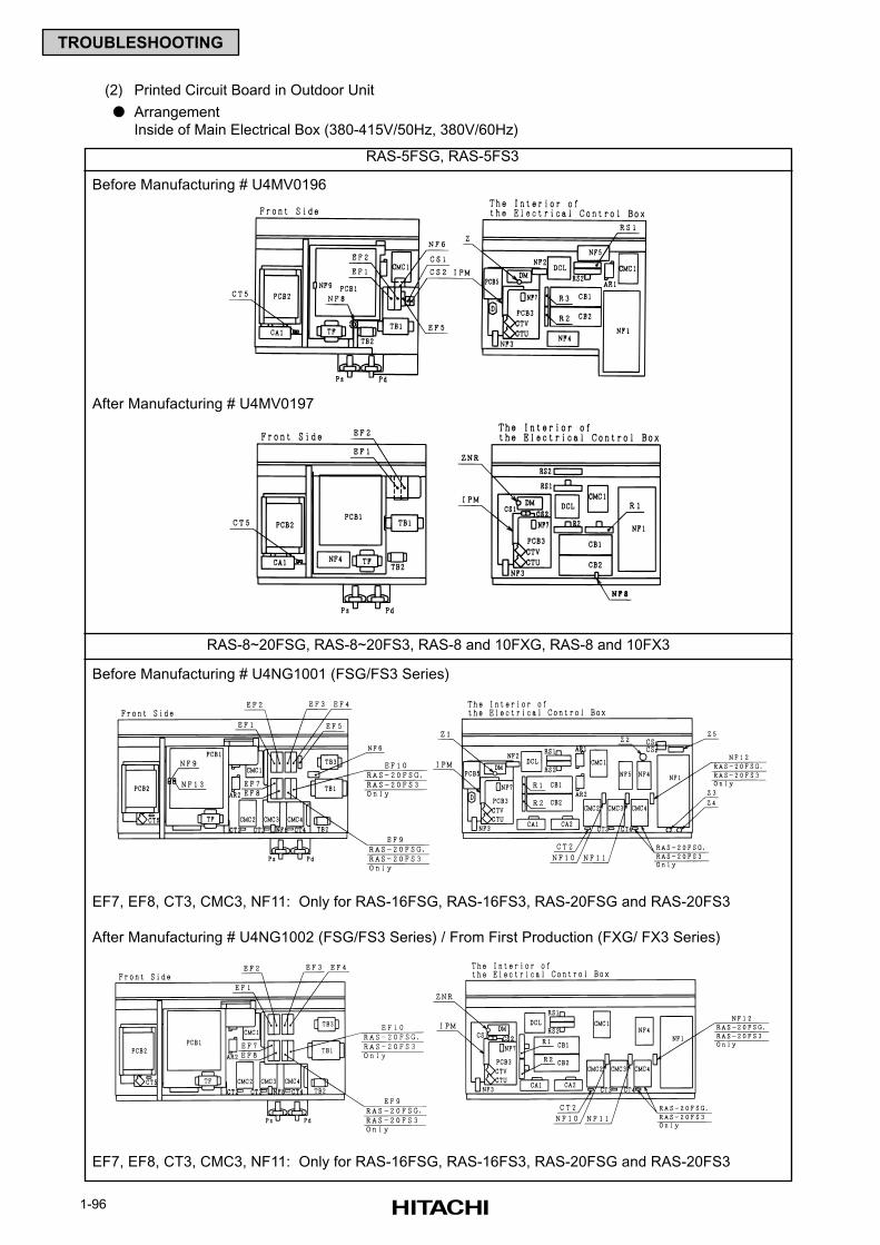
1-96
TROUBLESHOOTING
(2) Printed Circuit Board in Outdoor Unit
Arrangement
Inside of Main Electrical Box (380-415V/50Hz, 380V/60Hz)
RAS-5FSG, RAS-5FS3
RAS-8~20FSG, RAS-8~20FS3, RAS-8 and 10FXG, RAS-8 and 10FX3
Before Manufacturing # U4MV0196
After Manufacturing # U4MV0197
Before Manufacturing # U4NG1001 (FSG/FS3 Series)
EF7, EF8, CT3, CMC3, NF11: Only for RAS-16FSG, RAS-16FS3, RAS-20FSG and RAS-20FS3
After Manufacturing # U4NG1002 (FSG/FS3 Series) / From First Production (FXG/ FX3 Series)
EF7, EF8, CT3, CMC3, NF11: Only for RAS-16FSG, RAS-16FS3, RAS-20FSG and RAS-20FS3
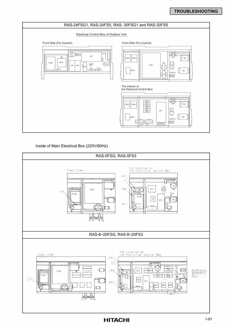
1-97
TROUBLESHOOTING
Inside of Main Electrical Box (220V/60Hz)
RAS-24FSG1, RAS-24FS5, RAS- 30FSG1 and RAS-30FS5
RAS-5FSG, RAS-5FS3
RAS-8~20FSG, RAS-8~20FS3
EF1
EF2
EF9CA2
ISPM
DCL
PCB2
R2
CMC1
TB5CB1 CB2
R1
Electrical Control Box of Outdoor Unit
Front Side (For Inverter)
C1
NF7
ZNF1
TB2TF2
CMC4
CMC2
CMC3
TF1
PCB1
TB1
TB4
TB3
Front Side (For Control)
The Interior ofthe Electrical Control Box
NF10
CMC3
TB2
CMC4
CMC2
TB4
TB1
TB3NF5
NF10
NF2 NF4NF3
EF3EF4EF5EF6EF7EF8
CA1 CA3 C2 C3 C4 C5
NF2NF3
NF4
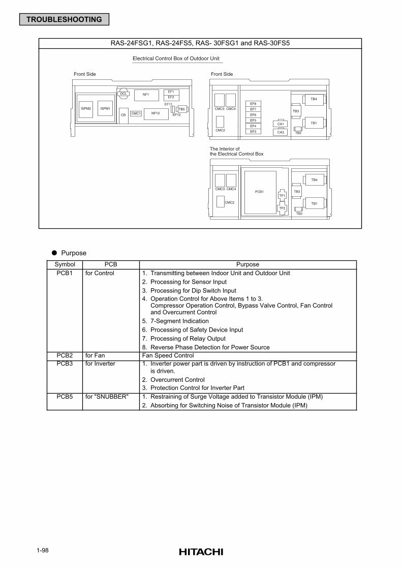
1-98
TROUBLESHOOTING
Purpose
Symbol PCB
PCB1 for Control 1. Transmitting between Indoor Unit and Outdoor Unit
2. Processing for Sensor Input
3. Processing for Dip Switch Input
4. Operation Control for Above Items 1 to 3.Compressor Operation Control, Bypass Valve Control, Fan Controland Overcurrent Control
5. 7-Segment Indication
6. Processing of Safety Device Input
7. Processing of Relay Output
8. Reverse Phase Detection for Power Source
PCB2 for Fan Fan Speed Control
PCB3 for Inverter 1. Inverter power part is driven by instruction of PCB1 and compressor
is driven.
2. Overcurrent Control
3. Protection Control for Inverter Part
PCB5 for "SNUBBER" 1. Restraining of Surge Voltage added to Transistor Module (IPM)
2. Absorbing for Switching Noise of Transistor Module (IPM)
Purpose
RAS-24FSG1, RAS-24FS5, RAS- 30FSG1 and RAS-30FS5
Front Side
NF1DCL
CMC1CB
EF1
EF2
TB5
EF11
EF12NF10
EF4
EF3
EF5
CA3
CA1
EF7
EF6
EF8
ISPM1ISPM2
The Interior ofthe Electrical Control Box
Front Side
TB1
TB3
TB4
TB2
PCB1
Electrical Control Box of Outdoor Unit
CMC3
CMC2
CMC4
CMC3
CMC2
CMC4
TF1
TF2
TB3
TB1
TB4
TB2
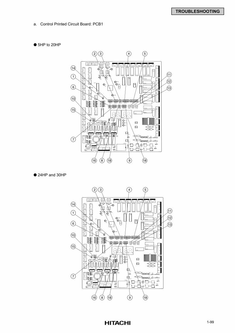
1-99
TROUBLESHOOTING
a. Control Printed Circuit Board: PCB1
5HP to 20HP
24HP and 30HP
2
14
16 18 18
12
11
13
10
15
1
6
7
8 9
3 4 5
2
14
16 18 18
12
11
13
10
15
1
6
7
8 9
3 4 5
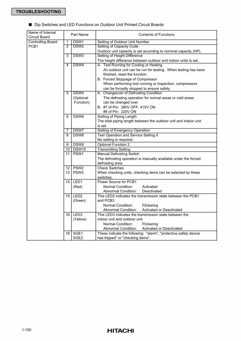
1-100
TROUBLESHOOTING
Dip Switches and LED Functions on Outdoor Unit Printed Circuit Boards
Name of Internal
Circuit Board
Controlling Board: 1 DSW1 Setting of Outdoor Unit Number
PCB1 2 DSW2 Setting of Capacity Code
Outdoor unit capacity is set according to nominal capacity (HP).
3 DSW3 Setting of Height Difference
The height difference between outdoor and indoor units is set.
4 DSW4 A. Test Running for Cooling or Heating
An outdoor unit can be run for testing. When testing has been
finished, reset the function.
B. Forced Stoppage of Compressor
When performing test running or inspection, compressors
can be forcedly stopped to ensure safety.
5 DSW5 A. Changeover of Defrosting Condition
(Optional The defrosting operation for normal areas or cold areas
Function) can be changed over.
B. #7 of Pin: 380V OFF, 415V ON
#8 of Pin: 220V ON
6 DSW6 Setting of Piping Length
The total piping length between the outdoor unit and indoor unit
is set.
7 DSW7 Setting of Emergency Operation
8 DSW8 Test Operation and Service Setting II
No setting is required.
9 DSW9 Optional Function 2
10 DSW10 Transmitting Setting
11 PSW1 Manual Defrosting Switch
The defrosting operation is manually available under the forced
defrosting area.
12 PSW2 Check Switches
13 PSW3 When checking units, checking items can be selected by these
switches.
14 LED1 Power Source for PCB1
(Red) Normal Condition: Activated
Abnormal Condition: Deactivated
15 LED2 This LED2 indicates the transmission state between the PCB1
(Green) and PCB3.
Normal Condition: Flickering
Abnormal Condition: Activated or Deactivated
16 LED3 This LED3 indicates the transmission state between the
(Yellow) indoor unit and outdoor unit.
Normal Condition: Flickering
Abnormal Condition: Activated or Deactivated
18 SGE1 These indicate the following: "alarm", "protective safety device
SGE2 has tripped" or "checking items".
Part Name Contents of Functions
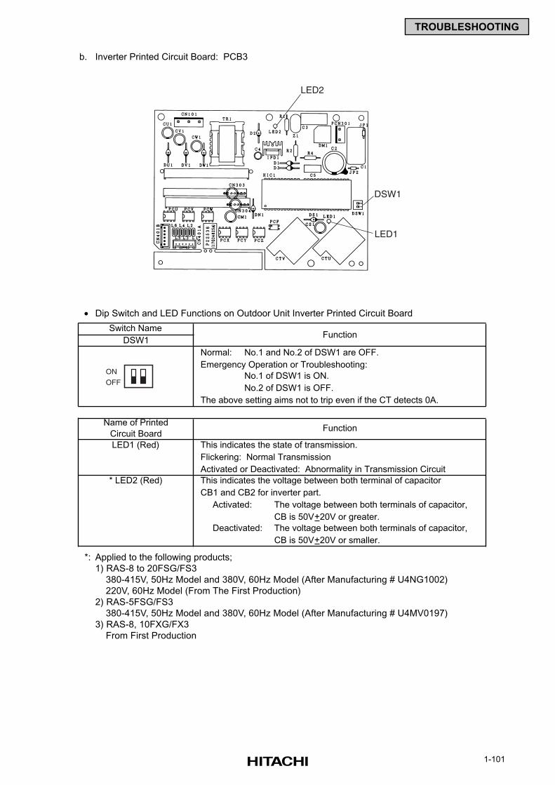
1-101
TROUBLESHOOTING
b. Inverter Printed Circuit Board: PCB3
• Dip Switch and LED Functions on Outdoor Unit Inverter Printed Circuit Board
*: Applied to the following products;
1) RAS-8 to 20FSG/FS3
380-415V, 50Hz Model and 380V, 60Hz Model (After Manufacturing # U4NG1002)
220V, 60Hz Model (From The First Production)
2) RAS-5FSG/FS3
380-415V, 50Hz Model and 380V, 60Hz Model (After Manufacturing # U4MV0197)
3) RAS-8, 10FXG/FX3
From First Production
Switch Name
DSW1
Normal: No.1 and No.2 of DSW1 are OFF.
Emergency Operation or Troubleshooting:
No.1 of DSW1 is ON.
No.2 of DSW1 is OFF.
The above setting aims not to trip even if the CT detects 0A.
Name of Printed
Circuit Board
LED1 (Red) This indicates the state of transmission.
Flickering: Normal Transmission
Activated or Deactivated: Abnormality in Transmission Circuit
* LED2 (Red) This indicates the voltage between both terminal of capacitor
CB1 and CB2 for inverter part.
Activated: The voltage between both terminals of capacitor,
CB is 50V+20V or greater.
Deactivated: The voltage between both terminals of capacitor,
CB is 50V+20V or smaller.
Function
Function
ON
OFF
LED2
DSW1
LED1
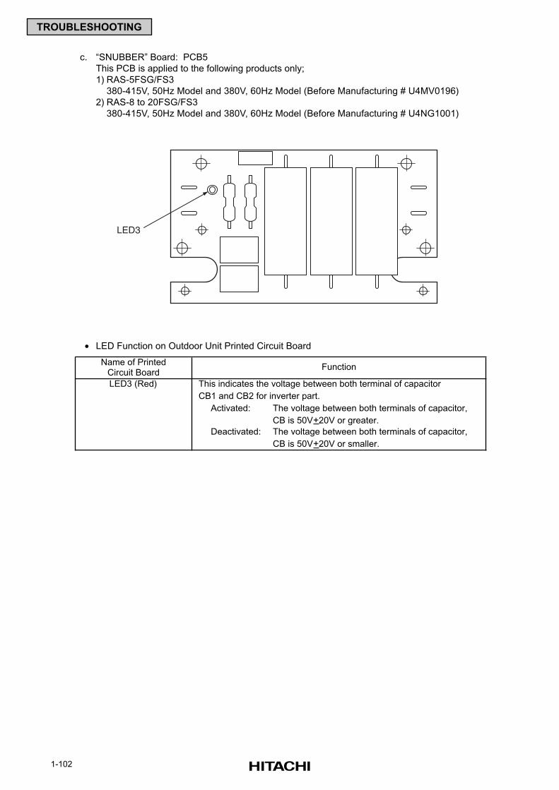
1-102
TROUBLESHOOTING
c. “SNUBBER” Board: PCB5
This PCB is applied to the following products only;
1) RAS-5FSG/FS3
380-415V, 50Hz Model and 380V, 60Hz Model (Before Manufacturing # U4MV0196)
2) RAS-8 to 20FSG/FS3
380-415V, 50Hz Model and 380V, 60Hz Model (Before Manufacturing # U4NG1001)
• LED Function on Outdoor Unit Printed Circuit Board
Name of PrintedCircuit Board
LED3 (Red) This indicates the voltage between both terminal of capacitor
CB1 and CB2 for inverter part.
Activated: The voltage between both terminals of capacitor,
CB is 50V+20V or greater.
Deactivated: The voltage between both terminals of capacitor,
CB is 50V+20V or smaller.
Function
LED3
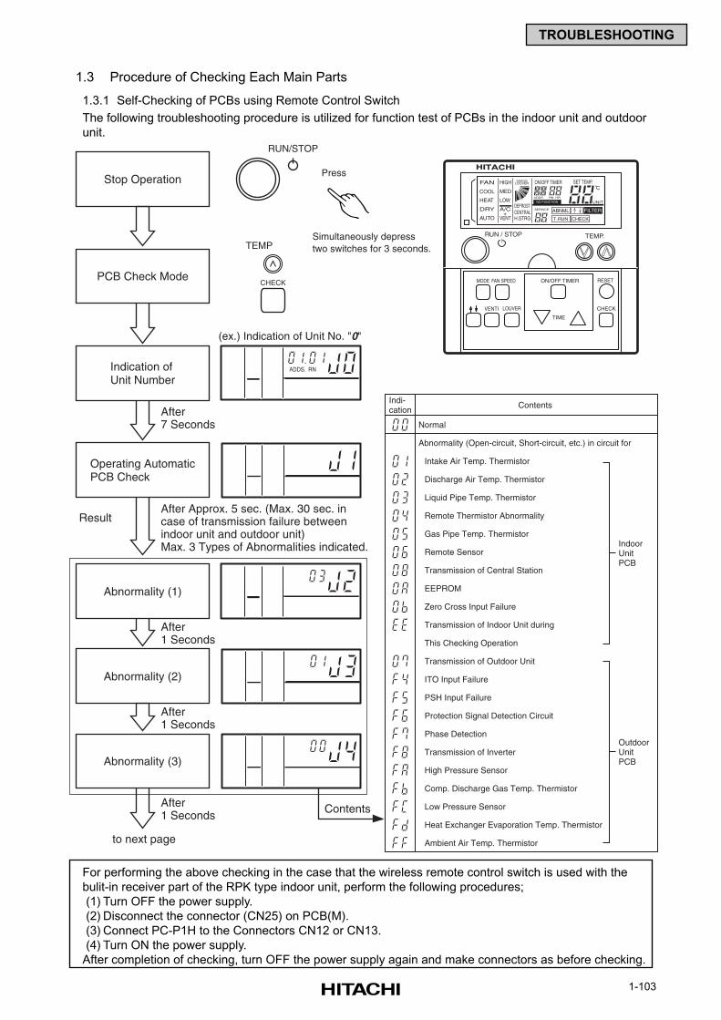
1-103
TROUBLESHOOTING
1.3 Procedure of Checking Each Main Parts
1.3.1 Self-Checking of PCBs using Remote Control Switch
The following troubleshooting procedure is utilized for function test of PCBs in the indoor unit and outdoor
unit.
Stop Operation
Simultaneously depresstwo switches for 3 seconds.
Press
TEMP
RUN/STOP
(ex.) Indication of Unit No. "0"
CHECK
Ambient Air Temp. Thermistor
ADDS. RN
PCB Check Mode
Indication ofUnit Number
Operating AutomaticPCB Check
Abnormality (3)
Abnormality (1)
After Approx. 5 sec. (Max. 30 sec. incase of transmission failure betweenindoor unit and outdoor unit)Max. 3 Types of Abnormalities indicated.
Result
After1 Seconds
After7 Seconds
After1 Seconds
After1 Seconds
to next page
Contents
Abnormality (2)
Heat Exchanger Evaporation Temp. Thermistor
Low Pressure Sensor
Comp. Discharge Gas Temp. Thermistor
High Pressure Sensor
Transmission of Inverter
Phase Detection
Protection Signal Detection Circuit
PSH Input Failure
ITO Input Failure
Transmission of Outdoor Unit
This Checking Operation
Transmission of Indoor Unit during
Zero Cross Input Failure
EEPROM
Transmission of Central Station
Remote Sensor
Gas Pipe Temp. Thermistor
Remote Thermistor Abnormality
Liquid Pipe Temp. Thermistor
Discharge Air Temp. Thermistor
Intake Air Temp. Thermistor
Abnormality (Open-circuit, Short-circuit, etc.) in circuit for
IndoorUnitPCB
OutdoorUnitPCB
Normal
ContentsIndi-cation
TEMP.RUN / STOP
MODE FAN SPEED
VENTI
RESET
CHECKLOUVER
ON/OFF TIMER
TIME
NO FUNCTION
FAN
COOL
HEAT
DRY
AUTO
HIGH
MED
LOW
A/C
VENT+
SWING
DEFROSTCENTRALH.STRG
SERVICE
ON/OFF TIMER SET TEMP.
RN HR
FILTER
T. RUN
ABNML
CHECK
ADDS
UNIT
LOUVER
For performing the above checking in the case that the wireless remote control switch is used with the
bulit-in receiver part of the RPK type indoor unit, perform the following procedures;
(1) Turn OFF the power supply.
(2) Disconnect the connector (CN25) on PCB(M).
(3) Connect PC-P1H to the Connectors CN12 or CN13.
(4) Turn ON the power supply.
After completion of checking, turn OFF the power supply again and make connectors as before checking.
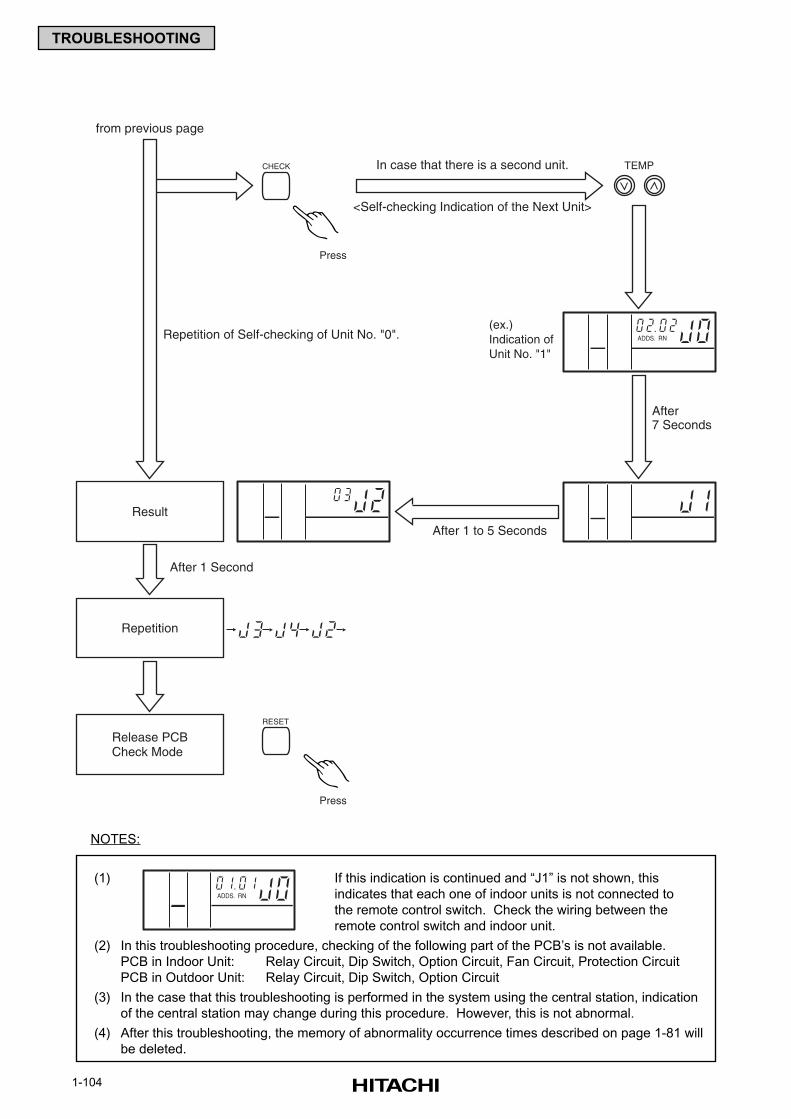
1-104
TROUBLESHOOTING
TEMP
Press
(ex.)Indication ofUnit No. "1"
CHECK
Press
RESET
ADDS. RN
Result
After 1 Second
After 1 to 5 Seconds
After7 Seconds
from previous page
Repetition of Self-checking of Unit No. "0".
In case that there is a second unit.
<Self-checking Indication of the Next Unit>
Repetition
Release PCBCheck Mode
NOTES:
(1) If this indication is continued and “J1” is not shown, this
indicates that each one of indoor units is not connected to
the remote control switch. Check the wiring between the
remote control switch and indoor unit.
(2) In this troubleshooting procedure, checking of the following part of the PCB’s is not available.
PCB in Indoor Unit: Relay Circuit, Dip Switch, Option Circuit, Fan Circuit, Protection Circuit
PCB in Outdoor Unit: Relay Circuit, Dip Switch, Option Circuit
(3) In the case that this troubleshooting is performed in the system using the central station, indication
of the central station may change during this procedure. However, this is not abnormal.
(4) After this troubleshooting, the memory of abnormality occurrence times described on page 1-81 will
be deleted.
ADDS. RN
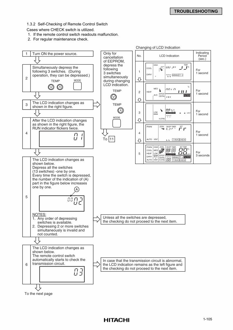
1-105
TROUBLESHOOTING
1.3.2 Self-Checking of Remote Control Switch
Cases where CHECK switch is utilized.
1. If the remote control switch readouts malfunction.
2. For regular maintenance check.
COOL
DRY
HIGH
+SERVICE
TEMP.
ABNML
NO FUNCTIONLOW
H.STRG
SERVICE
RN HRADDS
UNIT
FAN
AUTO VENT
SWING ON/OFF TIMER SET
T. RUN CHECK
LOUVER
NO FUNCTION
FAN
COOL
HEAT
DRY
AUTO
HIGH
MED
LOW
A/C
VENT+
SWING
DEFROSTCENTRALH.STRG
SERVICE
ON/OFF TIMER SET TEMP.
RN HR
FILTER
T. RUN
ABNML
CHECK
ADDS
UNIT
LOUVER
HEAT
MED
A/CDEFROSTCENTRAL FILTER
No.
1
LCD IndicationIndicating
Period(sec.)
For1 second
Changing of LCD Indication
2
3
4
5
For1 second
For1 second
For1 second
For3 seconds
MODE
1 Turn ON the power source.
3 The LCD indication changes asshown in the right figure.
To 11
2
Simultaneously depress thefollowing 3 switches. (Duringoperation, they can be depressed.)
TEMP
4
After the LCD indication changesas shown in the right figure, theRUN indicator flickers twice.
To the next page
6
The LCD indication changes asshown below.The remote control switchautomatically starts to check thetransmission circuit.
5
The LCD indication changes asshown below.Depress all the switches(13 switches) -one by one.Every time the switch is depressed,the number of the indication of (A)part in the figure below increasesone by one.
NOTES:1. Any order of depressing
switches is available.2. Depressing 2 or more switches
simultaneously is invalid andnot counted.
Unless all the switches are depressed,the checking do not proceed to the next item.
MODE
Only forcancellationof EEPROM,depress thefollowing3 switchessimultaneouslyduring changingLCD indication.
In case that the transmission circuit is abnormal,the LCD indication remains as the left figure andthe checking do not proceed to the next item.
TEMP
TEMP
A
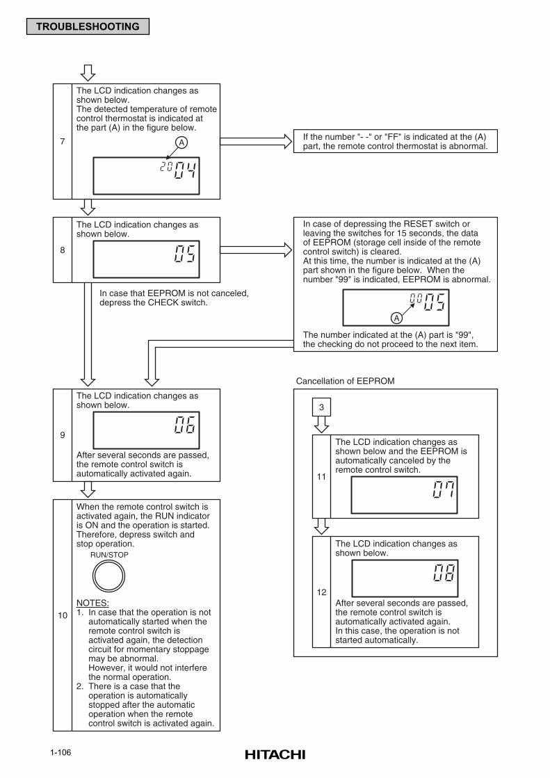
1-106
TROUBLESHOOTING
In case that EEPROM is not canceled,depress the CHECK switch.
3
7
The LCD indication changes asshown below.The detected temperature of remotecontrol thermostat is indicated atthe part (A) in the figure below.
Cancellation of EEPROM
8
The LCD indication changes asshown below.
9
The LCD indication changes asshown below.
After several seconds are passed,the remote control switch isautomatically activated again. 11
The LCD indication changes asshown below and the EEPROM isautomatically canceled by theremote control switch.
12
The LCD indication changes asshown below.
After several seconds are passed,the remote control switch isautomatically activated again.In this case, the operation is notstarted automatically.
10
When the remote control switch isactivated again, the RUN indicatoris ON and the operation is started.Therefore, depress switch andstop operation.
NOTES:1. In case that the operation is not
automatically started when theremote control switch isactivated again, the detectioncircuit for momentary stoppagemay be abnormal.However, it would not interferethe normal operation.
2. There is a case that theoperation is automaticallystopped after the automaticoperation when the remotecontrol switch is activated again.
A
In case of depressing the RESET switch orleaving the switches for 15 seconds, the dataof EEPROM (storage cell inside of the remotecontrol switch) is cleared.At this time, the number is indicated at the (A)part shown in the figure below. When thenumber "99" is indicated, EEPROM is abnormal.
The number indicated at the (A) part is "99",the checking do not proceed to the next item.
If the number "- -" or "FF" is indicated at the (A)part, the remote control thermostat is abnormal.
A
RUN/STOP
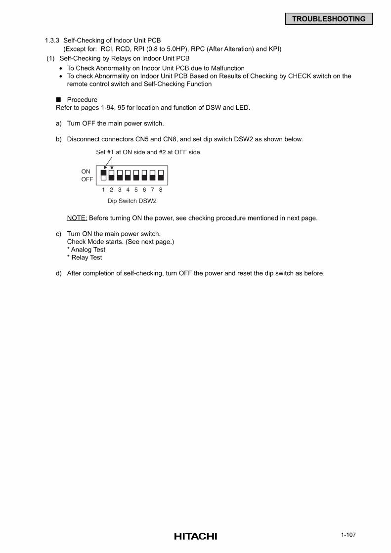
1-107
TROUBLESHOOTING
1.3.3 Self-Checking of Indoor Unit PCB
(Except for: RCI, RCD, RPI (0.8 to 5.0HP), RPC (After Alteration) and KPI)
(1) Self-Checking by Relays on Indoor Unit PCB
• To Check Abnormality on Indoor Unit PCB due to Malfunction
• To check Abnormality on Indoor Unit PCB Based on Results of Checking by CHECK switch on the
remote control switch and Self-Checking Function
Procedure
Refer to pages 1-94, 95 for location and function of DSW and LED.
a) Turn OFF the main power switch.
b) Disconnect connectors CN5 and CN8, and set dip switch DSW2 as shown below.
NOTE: Before turning ON the power, see checking procedure mentioned in next page.
c) Turn ON the main power switch.
Check Mode starts. (See next page.)
* Analog Test
* Relay Test
d) After completion of self-checking, turn OFF the power and reset the dip switch as before.
1
Dip Switch DSW2
Set #1 at ON side and #2 at OFF side.
ONOFF
2 3 4 5 6 7 8
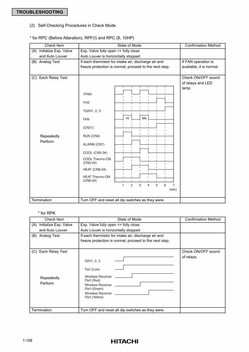
1-108
TROUBLESHOOTING
(2) Self-Checking Procedures in Check Mode
* for RPC (Before Alteration), RPF(I) and RPC (8, 10HP)
* for RPK
State of Mode Confirmation Method
(A) Initialize Exp. Valve Exp. Valve fully open => fully close
and Auto Louver Auto Louver is horizontally stopped.
(B) Analog Test If each thermistor for intake air, discharge air and If FAN operation is
freeze protection is normal, proceed to the next step. available, it is normal.
(C) Each Relay Test Check ON/OFF sound
of relays and LED
lamp.
Repeatedly
Perform
Termination Turn OFF and reset all dip switches as they were.
Check Item
State of Mode Confirmation Method
(A) Initialize Exp. Valve Exp. Valve fully open => fully close
and Auto Louver Auto Louver is horizontally stopped.
(B) Analog Test If each thermistor for intake air, discharge air and
freeze protection is normal, proceed to the next step.
(C) Each Relay Test Check ON/OFF sound
of relays.
Repeatedly
Perform
Termination Turn OFF and reset all dip switches as they were.
Check Item
52H1, 2, 3
Fan (Low)
Wireless ReceiverPart (Red)Wireless ReceiverPart (Green)Wireless ReceiverPart (Yellow)
YFAN
YH2
Y52H1, 2, 3
FAN
(CN21)
RUN (CN6)
ALARM (CN7)
COOL (CN5-3#)
COOL Thermo-ON(CN5-2#)
HEAT (CN8-2#)
HEAT Thermo-ON(CN8-3#)
Hi Me
1 2 3 4 5 6 7(sec)
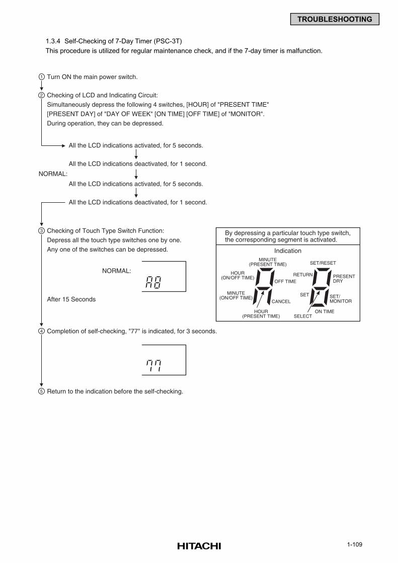
1-109
TROUBLESHOOTING
1.3.4 Self-Checking of 7-Day Timer (PSC-3T)
This procedure is utilized for regular maintenance check, and if the 7-day timer is malfunction.
By depressing a particular touch type switch,the corresponding segment is activated.
IndicationMINUTE
(PRESENT TIME)
HOUR(ON/OFF TIME)
HOUR(PRESENT TIME)
OFF TIME
CANCEL
MINUTE(ON/OFF TIME)
SET/RESET
RETURN
ON TIMESELECT
PRESENTDRY
SET/MONITOR
SET
Turn ON the main power switch.
All the LCD indications activated, for 5 seconds.
All the LCD indications deactivated, for 1 second.
All the LCD indications activated, for 5 seconds.
All the LCD indications deactivated, for 1 second.
After 15 Seconds
NORMAL:
NORMAL:
Completion of self-checking, "77" is indicated, for 3 seconds.
Return to the indication before the self-checking.
Checking of Touch Type Switch Function:
Depress all the touch type switches one by one.
Any one of the switches can be depressed.
Checking of LCD and Indicating Circuit:
Simultaneously depress the following 4 switches, [HOUR] of "PRESENT TIME"
[PRESENT DAY] of "DAY OF WEEK" [ON TIME] [OFF TIME] of "MONITOR".
During operation, they can be depressed.
2
1
3
4
5
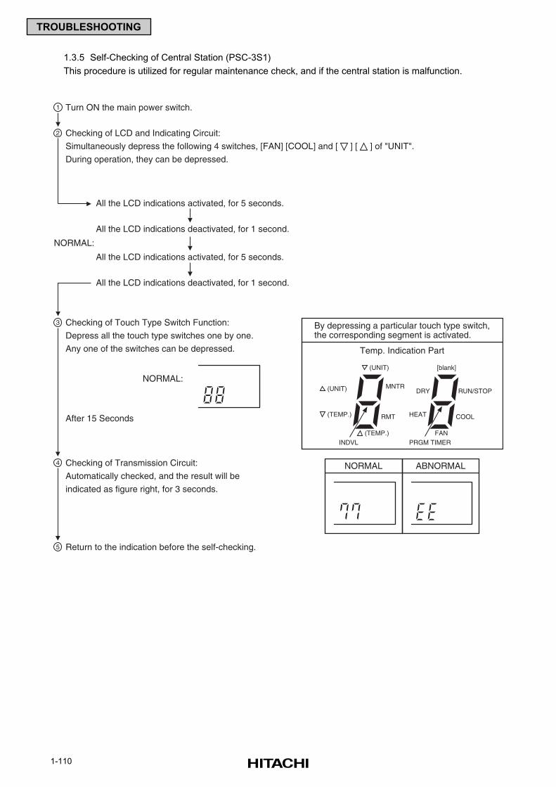
1-110
TROUBLESHOOTING
1.3.5 Self-Checking of Central Station (PSC-3S1)
This procedure is utilized for regular maintenance check, and if the central station is malfunction.
By depressing a particular touch type switch,the corresponding segment is activated.
Temp. Indication Part
(UNIT)
(UNIT) MNTR
RMT(TEMP.)
[blank]
DRY
FAN(TEMP.)PRGM TIMER
RUN/STOP
COOLHEAT
Turn ON the main power switch.
All the LCD indications activated, for 5 seconds.
All the LCD indications deactivated, for 1 second.
All the LCD indications activated, for 5 seconds.
All the LCD indications deactivated, for 1 second.
After 15 Seconds
NORMAL:
NORMALChecking of Transmission Circuit:
Automatically checked, and the result will be
indicated as figure right, for 3 seconds.
Return to the indication before the self-checking.
Checking of Touch Type Switch Function:
Depress all the touch type switches one by one.
Any one of the switches can be depressed.
Checking of LCD and Indicating Circuit:
Simultaneously depress the following 4 switches, [FAN] [COOL] and [ ] [ ] of "UNIT".
During operation, they can be depressed.
INDVL
2
1
3
4
5
ABNORMAL
NORMAL:
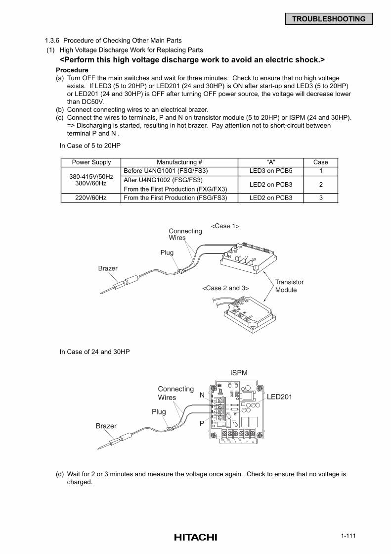
1-111
TROUBLESHOOTING
1.3.6 Procedure of Checking Other Main Parts
(1) High Voltage Discharge Work for Replacing Parts
<Perform this high voltage discharge work to avoid an electric shock.>
Procedure
(a) Turn OFF the main switches and wait for three minutes. Check to ensure that no high voltage
exists. If LED3 (5 to 20HP) or LED201 (24 and 30HP) is ON after start-up and LED3 (5 to 20HP)
or LED201 (24 and 30HP) is OFF after turning OFF power source, the voltage will decrease lower
than DC50V.
(b) Connect connecting wires to an electrical brazer.
(c) Connect the wires to terminals, P and N on transistor module (5 to 20HP) or ISPM (24 and 30HP).
=> Discharging is started, resulting in hot brazer. Pay attention not to short-circuit between
terminal P and N .
(d) Wait for 2 or 3 minutes and measure the voltage once again. Check to ensure that no voltage is
charged.
Power Supply Manufacturing # "A" Case
Before U4NG1001 (FSG/FS3) LED3 on PCB5 1
After U4NG1002 (FSG/FS3)
From the First Production (FXG/FX3)
220V/60Hz From the First Production (FSG/FS3) LED2 on PCB3 3
380-415V/50Hz380V/60Hz LED2 on PCB3 2
TB3
R S WRB
VT UNPD P
TB2
R216R215
ZN20LED201
ZN202
R201
R200
CN207 CN206
CN9
PC207
C
PC208CN8
RB
N
P
P1
Brazer
Plug
N
P
ConnectingWires LED201
ISPM
In Case of 24 and 30HP
In Case of 5 to 20HP
Brazer
Plug
ConnectingWires
PB
N U V W
TransistorModule
<Case 1>
<Case 2 and 3>
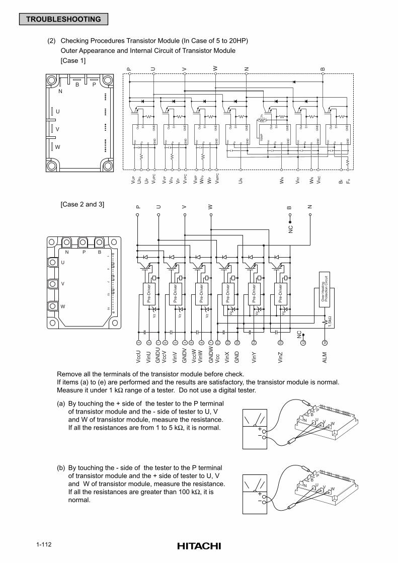
1-112
TROUBLESHOOTING
(2) Checking Procedures Transistor Module (In Case of 5 to 20HP)
Outer Appearance and Internal Circuit of Transistor Module
[Case 1]
[Case 2 and 3]
Remove all the terminals of the transistor module before check.
If items (a) to (e) are performed and the results are satisfactory, the transistor module is normal.
Measure it under 1 kΩ range of a tester. Do not use a digital tester.
(a) By touching the + side of the tester to the P terminal
of transistor module and the - side of tester to U, V
and W of transistor module, measure the resistance.
If all the resistances are from 1 to 5 kΩ, it is normal.
(b) By touching the - side of the tester to the P terminal
of transistor module and the + side of tester to U, V
and W of transistor module, measure the resistance.
If all the resistances are greater than 100 kΩ, it is
normal.
PB
N U V W
PB
N U V W
U
V
W
NB P
Vcc
Fo
In GN
D
Out S1
GN
D
VU
P
UF
o
UP
VU
PC
Vcc
Fo
In GN
D
Out S1
GN
D
VV
P
VF
o
VP
VV
PC
Vcc
Fo
In GN
D
Out S1
GN
D
VW
P
WF
o
WP
VW
PC
Vcc
Fo
In GN
D
Out S1
GN
D
UN
Vcc
Fo
In GN
D
Out S1
GN
D
WN
Vcc
Fo
In GN
D
Out S1
GN
D
VN
1
WN
VN
C
Vcc
Fo
In GN
D
Out S1
GN
D
Br
Fo
TE
MP
Th
P U V W N B
14
710
16
U
V
W
BPN
Pre
-Driv
er
Pre
-Driv
er
Pre
-Driv
er
Pre
-Driv
er
Pre
-Driv
er
Pre
-Driv
er
Ove
r H
eatin
g P
rote
ctio
n C
ircui
t
Vcc
UP U V W
Vin
U
GN
DU
Vcc
V
Vin
V
GN
DV
Vcc
WV
inW
GN
DW
Vcc
Vin
X
GN
D
Vin
Y
Vin
Z
ALM
NC
B N
NC
Vz
Vz
Vz V
z
Vz
Vz
3 2 1 6 5 4 9 8 7 11 13 10 14 15 12 16
1.5k
Ω
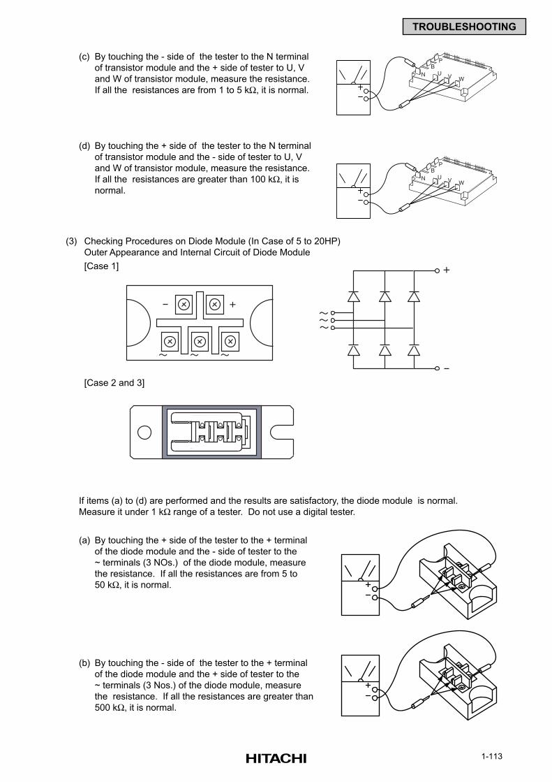
1-113
TROUBLESHOOTING
(c) By touching the - side of the tester to the N terminal
of transistor module and the + side of tester to U, V
and W of transistor module, measure the resistance.
If all the resistances are from 1 to 5 kΩ, it is normal.
(d) By touching the + side of the tester to the N terminal
of transistor module and the - side of tester to U, V
and W of transistor module, measure the resistance.
If all the resistances are greater than 100 kΩ, it is
normal.
[Case 2 and 3]
If items (a) to (d) are performed and the results are satisfactory, the diode module is normal.
Measure it under 1 kΩ range of a tester. Do not use a digital tester.
(a) By touching the + side of the tester to the + terminal
of the diode module and the - side of tester to the
~ terminals (3 NOs.) of the diode module, measure
the resistance. If all the resistances are from 5 to
50 kΩ, it is normal.
(b) By touching the - side of the tester to the + terminal
of the diode module and the + side of tester to the
~ terminals (3 Nos.) of the diode module, measure
the resistance. If all the resistances are greater than
500 kΩ, it is normal.
(3) Checking Procedures on Diode Module (In Case of 5 to 20HP)
Outer Appearance and Internal Circuit of Diode Module
[Case 1]
+
+
PB
N U V W
PB
N U V W
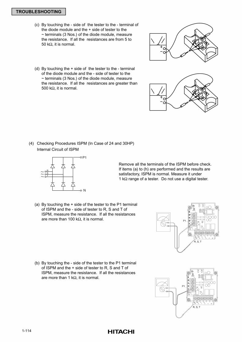
1-114
TROUBLESHOOTING
(c) By touching the - side of the tester to the - terminal of
the diode module and the + side of tester to the
~ terminals (3 Nos.) of the diode module, measure
the resistance. If all the resistances are from 5 to
50 kΩ, it is normal.
(d) By touching the + side of the tester to the - terminal
of the diode module and the - side of tester to the
~ terminals (3 Nos.) of the diode module, measure
the resistance. If all the resistances are greater than
500 kΩ, it is normal.
Remove all the terminals of the ISPM before check.
If items (a) to (h) are performed and the results are
satisfactory, ISPM is normal. Measure it under
1 kΩ range of a tester. Do not use a digital tester.
(a) By touching the + side of the tester to the P1 terminal
of ISPM and the - side of tester to R, S and T of
ISPM, measure the resistance. If all the resistances
are more than 100 kΩ, it is normal.
(b) By touching the - side of the tester to the P1 terminal
of ISPM and the + side of tester to R, S and T of
ISPM, measure the resistance. If all the resistances
are more than 1 kΩ, it is normal.
(4) Checking Procedures ISPM (In Case of 24 and 30HP)
Internal Circuit of ISPM
RST
P1
N
TB3
+
-
R S WRB
VT UNPD P
TB2
R216R215
ZN20LED201
ZN202
R201
R200
CN207 CN206
CN9
PC207
C
PC208CN8
RB
N
P
P1
P1
R, S, T
TB3
+
-
R S WRB
VT UNPD P
TB2
R216R215
ZN20LED201
ZN202
R201
R200
CN207 CN206
CN9
PC207
C
PC208CN8
RB
N
P
P1
P1
R, S, T
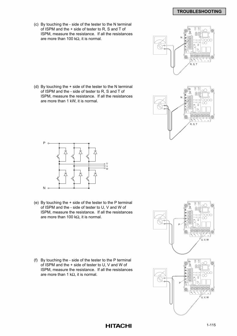
1-115
TROUBLESHOOTING
(c) By touching the - side of the tester to the N terminal
of ISPM and the + side of tester to R, S and T of
ISPM, measure the resistance. If all the resistances
are more than 100 kΩ, it is normal.
(d) By touching the + side of the tester to the N terminal
of ISPM and the - side of tester to R, S and T of
ISPM, measure the resistance. If all the resistances
are more than 1 kW, it is normal.
TB3
+
-
R S WRB
VT UNPD P
TB2
R216R215
ZN20LED201
ZN202
R201
R200
CN207 CN206
CN9
PC207
C
PC208CN8
RB
N
P
P1
N
R, S, T
TB3
+
-
R S WRB
VT UNPD P
TB2
R216R215
ZN20LED201
ZN202
R201
R200
CN207 CN206
CN9
PC207
C
PC208CN8
RB
N
P
P1
N
R, S, T
(e) By touching the + side of the tester to the P terminal
of ISPM and the - side of tester to U, V and W of
ISPM, measure the resistance. If all the resistances
are more than 100 kΩ, it is normal.
(f) By touching the - side of the tester to the P terminal
of ISPM and the + side of tester to U, V and W of
ISPM, measure the resistance. If all the resistances
are more than 1 kΩ, it is normal.
P
N
UVW
TB3
+
-
R S WRB
VT UNPD P
TB2
R216R215
ZN20LED201
ZN202
R201
R200
CN207 CN206
CN9
PC207
C
PC208CN8
RB
N
P
P1
U, V, W
P
TB3
+
-
R S WRB
VT UNPD P
TB2
R216R215
ZN20LED201
ZN202
R201
R200
CN207 CN206
CN9
PC207
C
PC208CN8
RB
N
P
P1
U, V, W
P

1-116
TROUBLESHOOTING
(g) By touching the - side of the tester to the N terminal
of ISPM and the + side of tester to U, V and W of
ISPM, measure the resistance. If all the resistances
are more than 100 kΩ, it is normal.
(h) By touching the + side of the tester to the N terminal
of ISPM and the - side of tester to U, V and W of
ISPM, measure the resistance. If all the resistances
are more than 1 kΩ, it is normal.
TB3
+
-
R S WRB
VT UNPD P
TB2
R216R215
ZN20LED201
ZN202
R201
R200
CN207 CN206
CN9
PC207
C
PC208CN8
RB
N
P
P1
U, V, W
N
TB3
+
-
R S WRB
VT UNPD P
TB2
R216R215
ZN20LED201
ZN202
R201
R200
CN207 CN206
CN9
PC207
C
PC208CN8
RB
N
P
P1
U, V, W
N
If item (i) to (m) are performed and the results are
satisfactory, ISPM is normal.
Measure it under 1 kΩ range of a tester.
Do not use a digital tester.
(i) Perform the item (a) to (h).
(j) By touching the + side of the tester to the RB terminal
of ISPM and the - side of tester to P terminal of ISPM.
If the resistance is more than 1 kΩ, it is normal.
(k) By touching the - side of the tester to the RB terminal
of ISPM and the + side of tester to P terminal of ISPM.
If the resistance is more than 100 kΩ, it is normal.
P1 PB
PN
N
TB3
+
-
R S WRB
VT UNPD P
TB2
R216R215
ZN20LED201
ZN202
R201
R200
CN207 CN206
CN9
PC207
C
PC208CN8
RB
N
P
P1
RB
P
TB3
+
-
R S WRB
VT UNPD P
TB2
R216R215
ZN20LED201
ZN202
R201
R200
CN207 CN206
CN9
PC207
C
PC208CN8
RB
N
P
P1
RB
P
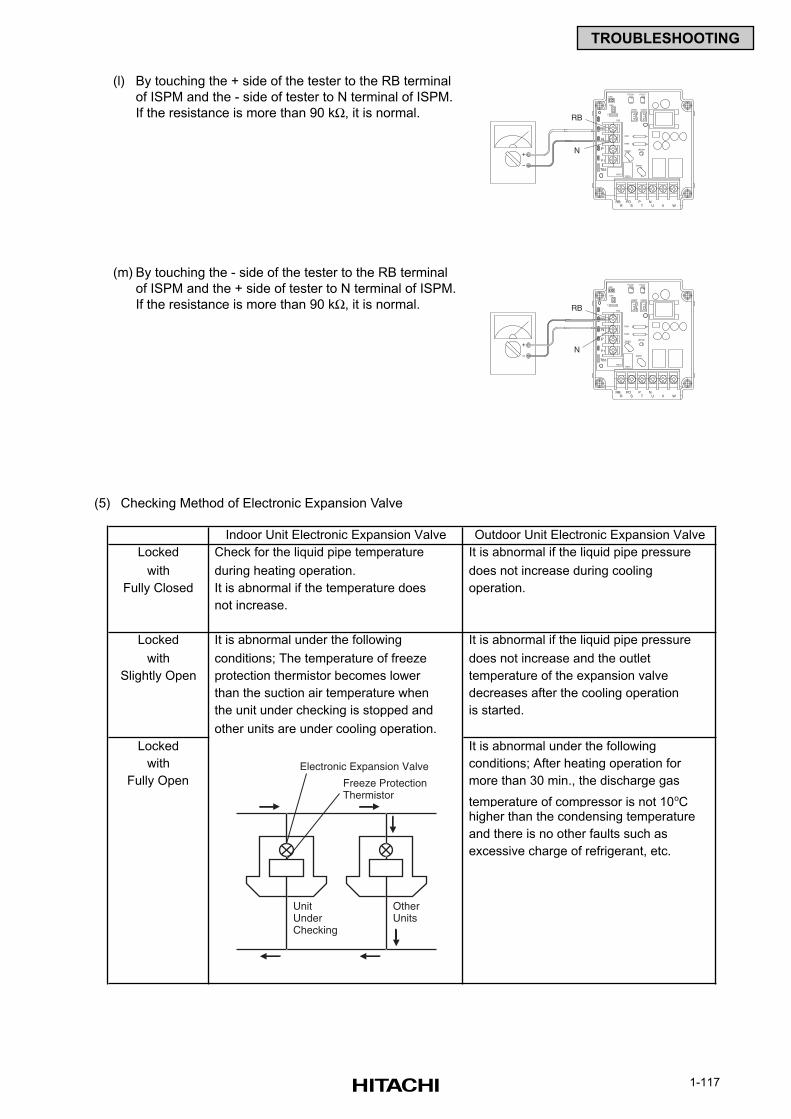
1-117
TROUBLESHOOTING
(5) Checking Method of Electronic Expansion Valve
Indoor Unit Electronic Expansion Valve Outdoor Unit Electronic Expansion Valve
Locked Check for the liquid pipe temperature It is abnormal if the liquid pipe pressure
with during heating operation. does not increase during cooling
Fully Closed It is abnormal if the temperature does operation.
not increase.
Locked It is abnormal under the following It is abnormal if the liquid pipe pressure
with conditions; The temperature of freeze does not increase and the outlet
Slightly Open protection thermistor becomes lower temperature of the expansion valve
than the suction air temperature when decreases after the cooling operation
the unit under checking is stopped and is started.
other units are under cooling operation.
Locked It is abnormal under the following
with conditions; After heating operation for
Fully Open more than 30 min., the discharge gas
temperature of compressor is not 10oC higher than the condensing temperature
and there is no other faults such as
excessive charge of refrigerant, etc.
(l) By touching the + side of the tester to the RB terminal
of ISPM and the - side of tester to N terminal of ISPM.
If the resistance is more than 90 kΩ, it is normal.
(m) By touching the - side of the tester to the RB terminal
of ISPM and the + side of tester to N terminal of ISPM.
If the resistance is more than 90 kΩ, it is normal.
TB3
+
-
R S WRB
VT UNPD P
TB2
R216R215
ZN20LED201
ZN202
R201
R200
CN207 CN206
CN9
PC207
C
PC208CN8
RB
N
P
P1
RB
N
TB3
+
-
R S WRB
VT UNPD P
TB2
R216R215
ZN20LED201
ZN202
R201
R200
CN207 CN206
CN9
PC207
C
PC208CN8
RB
N
P
P1
RB
N
UnitUnderChecking
Electronic Expansion Valve
Freeze ProtectionThermistor
OtherUnits
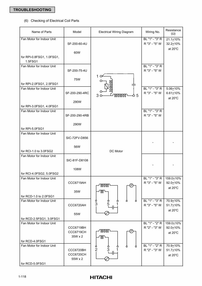
1-118
TROUBLESHOOTING
(6) Checking of Electrical Coil Parts
Name of Parts Model Electrical Wiring Diagram Wiring No.Resistance
(Ω)
Fan Motor for Indoor Unit BL "1" - "3" R 21.1+10%
SF-200-60-4U R "3" - "5" W 32.2+10%
at 20oC
60W
for RPI-0.8FSG1, 1.0FSG1,
1.5FSG1
Fan Motor for Indoor Unit BL "1" - "3" R
SF-200-75-4U R "3" - "5" W
75W
for RPI-2.0FSG1, 2.5FSG1
Fan Motor for Indoor Unit BL "1" - "3" R 5.06+10%
SF-200-290-4RC R "3" - "5" W 6.61+10%
at 20oC
290W
for RPI-3.0FSG1, 4.0FSG1
Fan Motor for Indoor Unit BL "1" - "3" R
SF-200-290-4RB R "3" - "5" W
290W
for RPI-5.0FSG1
Fan Motor for Indoor Unit
SIC-72FV-D856
- -
56W
for RCI-1.0 to 3.0FSG2 DC Motor
Fan Motor for Indoor Unit
SIC-81F-D8108
- -
108W
for RCI-4.0FSG2, 5.0FSG2
Fan Motor for Indoor Unit BL "1" - "3" R 159.0+10%
CCC6719AH R "3" - "5" W 92.0+10%
at 20oC
35W
for RCD-1.0 to 2.0FSG1
Fan Motor for Indoor Unit BL "1" - "3" R 70.9+10%
CCC6720AH R "3" - "5" W 51.7+10%
at 20oC
55W
for RCD-2.5FSG1, 3.0FSG1
Fan Motor for Indoor Unit BL "1" - "2" R 159.0+10%
CCC6719BH R "2" - "3" W 92.0+10%
CCC6719CH at 20oC
35W x 2
for RCD-4.0FSG1
Fan Motor for Indoor Unit BL "1" - "2" R 70.9+10%
CCC6720BH R "2" - "3" W 51.7+10%
CCC6720CH at 20oC
55W x 2
for RCD-5.0FSG1
1
3 5
153
P
132
P
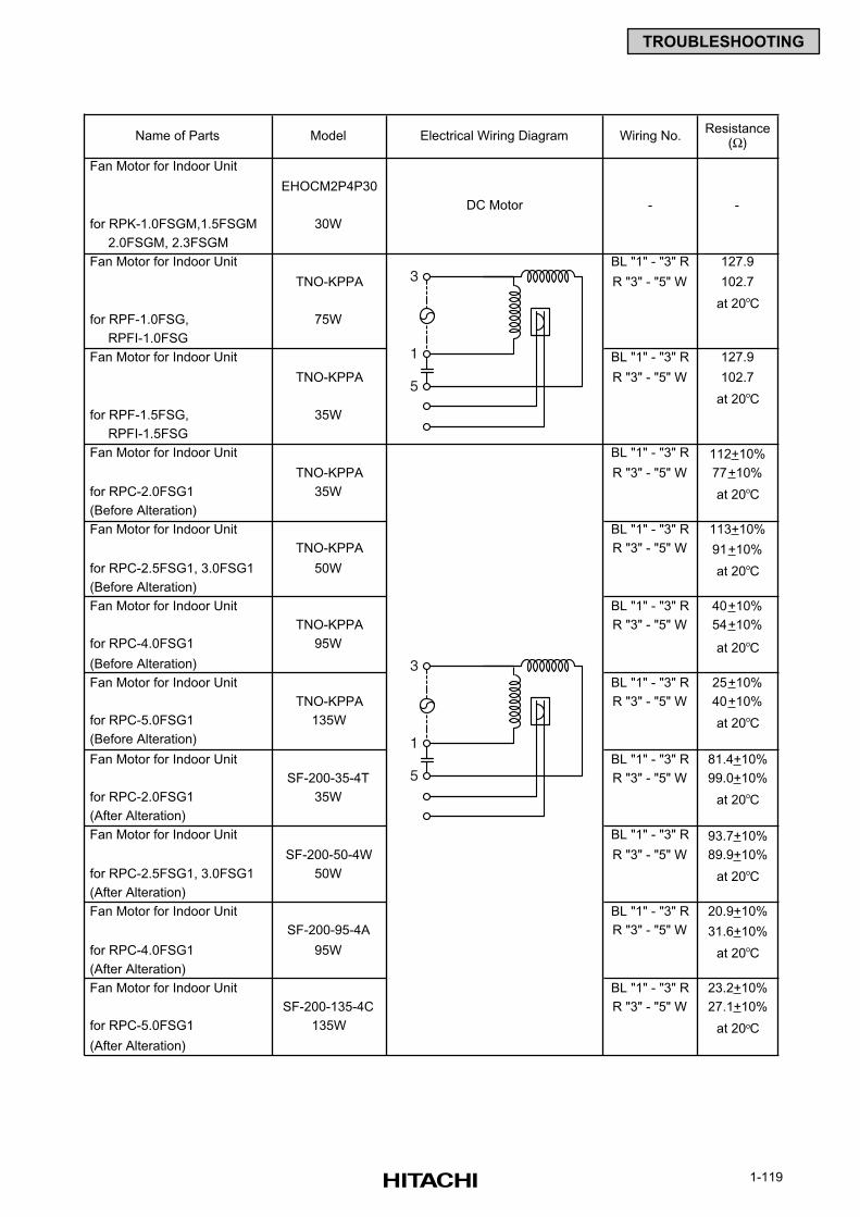
1-119
TROUBLESHOOTING
Name of Parts Model Electrical Wiring Diagram Wiring No.Resistance
(Ω)
Fan Motor for Indoor Unit
EHOCM2P4P30
DC Motor - -
for RPK-1.0FSGM,1.5FSGM 30W
2.0FSGM, 2.3FSGM
Fan Motor for Indoor Unit BL "1" - "3" R 127.9
TNO-KPPA R "3" - "5" W 102.7
at 20oC
for RPF-1.0FSG, 75W
RPFI-1.0FSG
Fan Motor for Indoor Unit BL "1" - "3" R 127.9
TNO-KPPA R "3" - "5" W 102.7
at 20oC
for RPF-1.5FSG, 35W
RPFI-1.5FSG
Fan Motor for Indoor Unit BL "1" - "3" R 112+10%
TNO-KPPA R "3" - "5" W 77+10%
for RPC-2.0FSG1 35W at 20oC
(Before Alteration)
Fan Motor for Indoor Unit BL "1" - "3" R 113+10%
TNO-KPPA R "3" - "5" W 91+10%
for RPC-2.5FSG1, 3.0FSG1 50W at 20oC
(Before Alteration)
Fan Motor for Indoor Unit BL "1" - "3" R 40+10%
TNO-KPPA R "3" - "5" W 54+10%
for RPC-4.0FSG1 95W at 20oC
(Before Alteration)
Fan Motor for Indoor Unit BL "1" - "3" R 25+10%
TNO-KPPA R "3" - "5" W 40+10%
for RPC-5.0FSG1 135W at 20oC
(Before Alteration)
Fan Motor for Indoor Unit BL "1" - "3" R 81.4+10%
SF-200-35-4T R "3" - "5" W 99.0+10%
for RPC-2.0FSG1 35W at 20oC
(After Alteration)
Fan Motor for Indoor Unit BL "1" - "3" R 93.7+10%
SF-200-50-4W R "3" - "5" W 89.9+10%
for RPC-2.5FSG1, 3.0FSG1 50W at 20oC
(After Alteration)
Fan Motor for Indoor Unit BL "1" - "3" R 20.9+10%
SF-200-95-4A R "3" - "5" W 31.6+10%
for RPC-4.0FSG1 95W at 20oC
(After Alteration)
Fan Motor for Indoor Unit BL "1" - "3" R 23.2+10%
SF-200-135-4C R "3" - "5" W 27.1+10%
for RPC-5.0FSG1 135W at 20oC
(After Alteration)
1
3
5
1
3
5
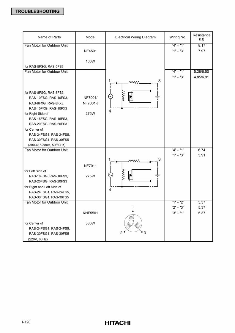
1-120
TROUBLESHOOTING
Name of Parts Model Electrical Wiring Diagram Wiring No.Resistance
(Ω)
Fan Motor for Outdoor Unit "4" - "1" 8.17
NF4501 "1" - "3" 7.97
160W
for RAS-5FSG, RAS-5FS3
Fan Motor for Outdoor Unit "4" - "1" 5.28/6.50
"1" - "3" 4.85/6.91
for RAS-8FSG, RAS-8FS3,
RAS-10FSG, RAS-10FS3, NF7001/
RAS-8FXG, RAS-8FX3, NF7001K
RAS-10FXG, RAS-10FX3
for Right Side of 275W
RAS-16FSG, RAS-16FS3,
RAS-20FSG, RAS-20FS3
for Center of
RAS-24FSG1, RAS-24FS5,
RAS-30FSG1, RAS-30FS5
(380-415/380V, 50/60Hz)
Fan Motor for Outdoor Unit "4" - "1" 6.74
"1" - "3" 5.91
NF7011
for Left Side of
RAS-16FSG, RAS-16FS3, 275W
RAS-20FSG, RAS-20FS3
for Right and Left Side of
RAS-24FSG1, RAS-24FS5,
RAS-30FSG1, RAS-30FS5
Fan Motor for Outdoor Unit "1" - "2" 5.37
"2" - "3" 5.37
KNF5501 "3" - "1" 5.37
for Center of 380W
RAS-24FSG1, RAS-24FS5,
RAS-30FSG1, RAS-30FS5
(220V, 60Hz)
4
1 3
4
1 3
1
2 3
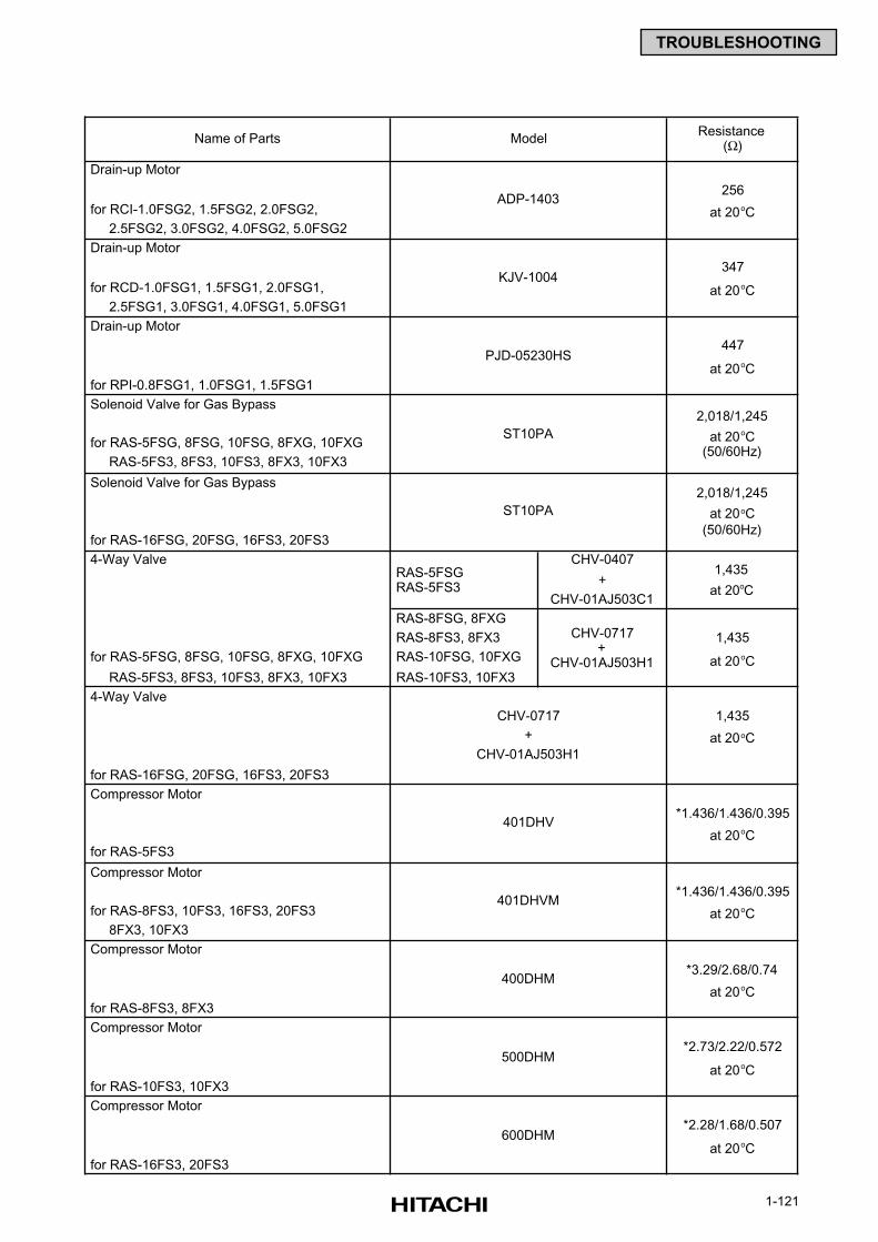
1-121
TROUBLESHOOTING
Name of PartsResistance
(Ω)
Drain-up Motor
256
for RCI-1.0FSG2, 1.5FSG2, 2.0FSG2, at 20oC
2.5FSG2, 3.0FSG2, 4.0FSG2, 5.0FSG2
Drain-up Motor
347
for RCD-1.0FSG1, 1.5FSG1, 2.0FSG1, at 20oC
2.5FSG1, 3.0FSG1, 4.0FSG1, 5.0FSG1
Drain-up Motor
447
at 20oC
for RPI-0.8FSG1, 1.0FSG1, 1.5FSG1
Solenoid Valve for Gas Bypass
for RAS-5FSG, 8FSG, 10FSG, 8FXG, 10FXG
RAS-5FS3, 8FS3, 10FS3, 8FX3, 10FX3
Solenoid Valve for Gas Bypass
for RAS-16FSG, 20FSG, 16FS3, 20FS3
4-Way Valve CHV-0407
+
CHV-01AJ503C1
RAS-8FSG, 8FXG
RAS-8FS3, 8FX3 1,435
for RAS-5FSG, 8FSG, 10FSG, 8FXG, 10FXG RAS-10FSG, 10FXG at 20oC
RAS-5FS3, 8FS3, 10FS3, 8FX3, 10FX3 RAS-10FS3, 10FX3
4-Way Valve
1,435
at 20oC
for RAS-16FSG, 20FSG, 16FS3, 20FS3
Compressor Motor
*1.436/1.436/0.395
at 20oC
for RAS-5FS3
Compressor Motor
*1.436/1.436/0.395
for RAS-8FS3, 10FS3, 16FS3, 20FS3 at 20oC
8FX3, 10FX3
Compressor Motor
*3.29/2.68/0.74
at 20oC
for RAS-8FS3, 8FX3
Compressor Motor
*2.73/2.22/0.572
at 20oC
for RAS-10FS3, 10FX3
Compressor Motor
*2.28/1.68/0.507
at 20oC
for RAS-16FS3, 20FS3
600DHM
CHV-0717
+
CHV-01AJ503H1
401DHV
401DHVM
400DHM
500DHM
2,018/1,245
at 20oC(50/60Hz)
Model
ADP-1403
KJV-1004
PJD-05230HS
ST10PA
CHV-0717+
CHV-01AJ503H1
RAS-5FSG RAS-5FS3
1,435
at 20oC
2,018/1,245
at 20oC
(50/60Hz)
ST10PA
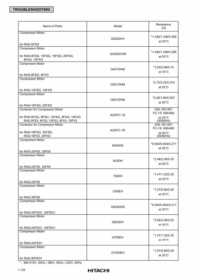
1-122
TROUBLESHOOTING
Name of Parts ModelResistance
(Ω)
Compressor Motor
*1.436/1.436/0.395
at 20oC for RAS-5FSG
Compressor Motor
*1.436/1.436/0.395
for RAS-8FSG, 10FSG, 16FSG, 20FSG, at 20oC 8FXG, 10FXG
Compressor Motor
*3.29/2.68/0.74
at 20oC for RAS-8FSG, 8FXG
Compressor Motor
*2.73/2.22/0.572
at 20oC for RAS-10FSG, 10FXG
Compressor Motor
*2.28/1.68/0.507
at 20oC for RAS-16FSG, 20FSG
Contactor for Compressor Motor A25: 501/401
FC-1S: 656/460
for RAS-5FSG, 8FSG, 10FSG, 8FXG, 10FXG at 20oC RAS-5FS3, 8FS3, 10FS3, 8FX3, 10FX3 (50/60Hz)
Contactor for Compressor Motor A35: 501/401
FC-1S: 656/460
for RAS-16FSG, 20FSG, at 20oC RAS-16FS3, 20FS3 (50/60Hz)
Compressor Motor
*0.944/0.944/0.211
at 20oC for RAS-24FS5, 30FS5
Compressor Motor
*2.48/2.06/0.53
at 20oC for RAS-24FS5, 30FS5
Compressor Motor
*1.47/1.32/0.35
at 20oC for RAS-24FS5
Compressor Motor
*1.07/0.90/0.25
at 20oC for RAS-30FS5
Compressor Motor
*0.944/0.944/0.211
at 20oC for RAS-24FSG1, 30FSG1
Compressor Motor
*2.48/2.06/0.53
at 20oC for RAS-24FSG1, 30FSG1
Compressor Motor
*1.47/1.32/0.35
at 20oC for RAS-24FSG1
Compressor Motor
*1.07/0.90/0.25
at 20oC for RAS-30FSG1
*: 380-415V, 50Hz / 380V, 60Hz / 220V, 60Hz
G404DHD
G603DH
G750EH
G1200EH
404DHD
603DH
750EH
1200EH
A25/FC-1S
A35/FC-1S
G601DHM
G402DHV
G402DHVM
G401DHM
G501DHM
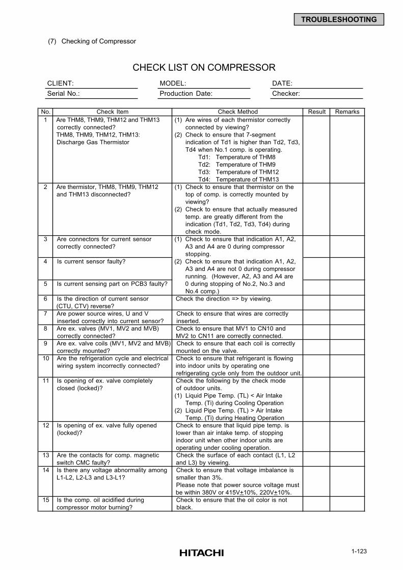
1-123
TROUBLESHOOTING
(7) Checking of Compressor
CLIENT: MODEL: DATE:
Serial No.: Production Date: Checker:
CHECK LIST ON COMPRESSOR
No. Check Item Result Remarks
1 Are THM8, THM9, THM12 and THM13 (1) Are wires of each thermistor correctly
correctly connected? connected by viewing?
THM8, THM9, THM12, THM13: (2) Check to ensure that 7-segment
Discharge Gas Thermistor indication of Td1 is higher than Td2, Td3,
Td4 when No.1 comp. is operating.
Td1: Temperature of THM8
Td2: Temperature of THM9
Td3: Temperature of THM12
Td4: Temperature of THM13
2 Are thermistor, THM8, THM9, THM12 (1) Check to ensure that thermistor on the
and THM13 disconnected? top of comp. is correctly mounted by
viewing?
(2) Check to ensure that actually measured
temp. are greatly different from the
indication (Td1, Td2, Td3, Td4) during
check mode.
3 Are connectors for current sensor (1) Check to ensure that indication A1, A2,
correctly connected? A3 and A4 are 0 during compressor
stopping.
4 Is current sensor faulty? (2) Check to ensure that indication A1, A2,
A3 and A4 are not 0 during compressor
running. (However, A2, A3 and A4 are
5 Is current sensing part on PCB3 faulty? 0 during stopping of No.2, No.3 and
No.4 comp.)
6 Is the direction of current sensor Check the direction => by viewing.
(CTU, CTV) reverse?
7 Are power source wires, U and V Check to ensure that wires are correctly
inserted correctly into current sensor? inserted.
8 Are ex. valves (MV1, MV2 and MVB) Check to ensure that MV1 to CN10 and
correctly connected? MV2 to CN11 are correctly connected.
9 Are ex. valve coils (MV1, MV2 and MVB) Check to ensure that each coil is correctly
correctly mounted? mounted on the valve.
10 Are the refrigeration cycle and electrical Check to ensure that refrigerant is flowing
wiring system incorrectly connected? into indoor units by operating one
refrigerating cycle only from the outdoor unit.
11 Is opening of ex. valve completely Check the following by the check mode
closed (locked)? of outdoor units.
(1) Liquid Pipe Temp. (TL) < Air Intake
Temp. (Ti) during Cooling Operation
(2) Liquid Pipe Temp. (TL) > Air Intake
Temp. (Ti) during Heating Operation
12 Is opening of ex. valve fully opened Check to ensure that liquid pipe temp. is
(locked)? lower than air intake temp. of stopping
indoor unit when other indoor units are
operating under cooling operation.
13 Are the contacts for comp. magnetic Check the surface of each contact (L1, L2
switch CMC faulty? and L3) by viewing.
14 Is there any voltage abnormality among Check to ensure that voltage imbalance is
L1-L2, L2-L3 and L3-L1? smaller than 3%.
Please note that power source voltage must
be within 380V or 415V+10%, 220V+10%.
15 Is the comp. oil acidified during Check to ensure that the oil color is not
compressor motor burning? black.
Check Method
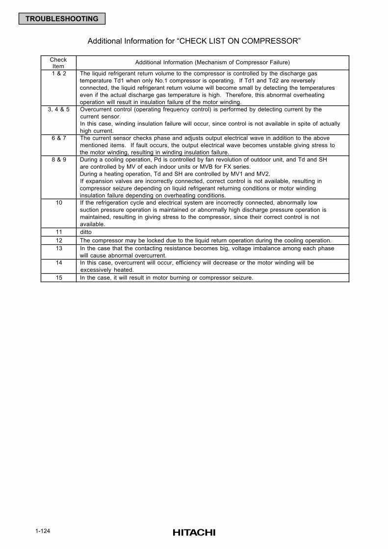
1-124
TROUBLESHOOTING
Additional Information for “CHECK LIST ON COMPRESSOR”
CheckItem
Additional Information (Mechanism of Compressor Failure)
1 & 2 The liquid refrigerant return volume to the compressor is controlled by the discharge gas
temperature Td1 when only No.1 compressor is operating. If Td1 and Td2 are reversely
connected, the liquid refrigerant return volume will become small by detecting the temperatures
even if the actual discharge gas temperature is high. Therefore, this abnormal overheating
operation will result in insulation failure of the motor winding.
3, 4 & 5 Overcurrent control (operating frequency control) is performed by detecting current by the
current sensor.
In this case, winding insulation failure will occur, since control is not available in spite of actually
high current.
6 & 7 The current sensor checks phase and adjusts output electrical wave in addition to the above
mentioned items. If fault occurs, the output electrical wave becomes unstable giving stress to
the motor winding, resulting in winding insulation failure.
8 & 9 During a cooling operation, Pd is controlled by fan revolution of outdoor unit, and Td and SH
are controlled by MV of each indoor units or MVB for FX series.
During a heating operation, Td and SH are controlled by MV1 and MV2.
If expansion valves are incorrectly connected, correct control is not available, resulting in
compressor seizure depending on liquid refrigerant returning conditions or motor winding
insulation failure depending on overheating conditions.
10 If the refrigeration cycle and electrical system are incorrectly connected, abnormally low
suction pressure operation is maintained or abnormally high discharge pressure operation is
maintained, resulting in giving stress to the compressor, since their correct control is not
available.
11 ditto
12 The compressor may be locked due to the liquid return operation during the cooling operation.
13 In the case that the contacting resistance becomes big, voltage imbalance among each phase
will cause abnormal overcurrent.
14 In this case, overcurrent will occur, efficiency will decrease or the motor winding will be
excessively heated.
15 In the case, it will result in motor burning or compressor seizure.
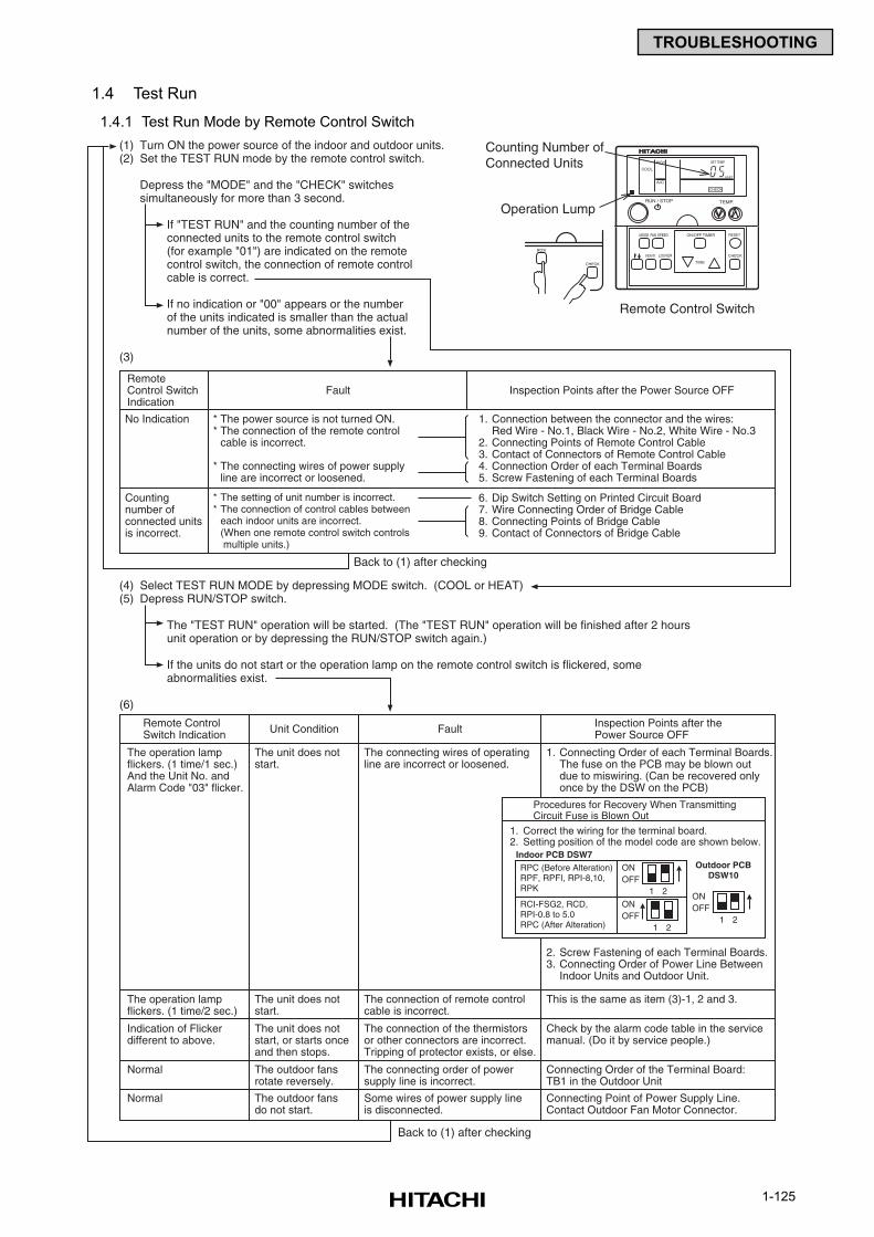
1-125
TROUBLESHOOTING
1.4 Test Run
1.4.1 Test Run Mode by Remote Control Switch
(1) Turn ON the power source of the indoor and outdoor units.(2) Set the TEST RUN mode by the remote control switch.
Depress the "MODE" and the "CHECK" switchessimultaneously for more than 3 second.
If "TEST RUN" and the counting number of theconnected units to the remote control switch(for example "01") are indicated on the remotecontrol switch, the connection of remote controlcable is correct.
If no indication or "00" appears or the numberof the units indicated is smaller than the actualnumber of the units, some abnormalities exist.
(3)
Back to (1) after checking
Back to (1) after checking
(4) Select TEST RUN MODE by depressing MODE switch. (COOL or HEAT)(5) Depress RUN/STOP switch.
The "TEST RUN" operation will be started. (The "TEST RUN" operation will be finished after 2 hoursunit operation or by depressing the RUN/STOP switch again.)
If the units do not start or the operation lamp on the remote control switch is flickered, someabnormalities exist.
(6)
RemoteControl SwitchIndication
No Indication * The power source is not turned ON.* The connection of the remote control
cable is incorrect.
* The connecting wires of power supplyline are incorrect or loosened.
1. Connection between the connector and the wires:Red Wire - No.1, Black Wire - No.2, White Wire - No.3
2. Connecting Points of Remote Control Cable3. Contact of Connectors of Remote Control Cable4. Connection Order of each Terminal Boards5. Screw Fastening of each Terminal Boards
6. Dip Switch Setting on Printed Circuit Board7. Wire Connecting Order of Bridge Cable8. Connecting Points of Bridge Cable9. Contact of Connectors of Bridge Cable
* The setting of unit number is incorrect.* The connection of control cables between
each indoor units are incorrect.(When one remote control switch controls multiple units.)
Countingnumber ofconnected unitsis incorrect.
Fault Inspection Points after the Power Source OFF
Remote ControlSwitch Indication
The operation lampflickers. (1 time/1 sec.)And the Unit No. andAlarm Code "03" flicker.
The unit does notstart.
The connecting wires of operatingline are incorrect or loosened.
The unit does notstart.
The connection of remote controlcable is incorrect.
This is the same as item (3)-1, 2 and 3.
The unit does notstart, or starts onceand then stops.
The connection of the thermistorsor other connectors are incorrect.Tripping of protector exists, or else.
Check by the alarm code table in the servicemanual. (Do it by service people.)
The outdoor fansrotate reversely.
The connecting order of powersupply line is incorrect.
Connecting Order of the Terminal Board:TB1 in the Outdoor Unit
The outdoor fansdo not start.
Some wires of power supply lineis disconnected.
Connecting Point of Power Supply Line.Contact Outdoor Fan Motor Connector.
1. Connecting Order of each Terminal Boards.The fuse on the PCB may be blown outdue to miswiring. (Can be recovered onlyonce by the DSW on the PCB)
2. Screw Fastening of each Terminal Boards.3. Connecting Order of Power Line Between
Indoor Units and Outdoor Unit.
The operation lampflickers. (1 time/2 sec.)
Indication of Flickerdifferent to above.
Normal
Normal
Unit Condition Fault Inspection Points after thePower Source OFF
Procedures for Recovery When TransmittingCircuit Fuse is Blown Out
1. Correct the wiring for the terminal board.2. Setting position of the model code are shown below.
ONOFF
1 2
Outdoor PCBDSW10
ONOFF
1 2
Indoor PCB DSW7RPC (Before Alteration)RPF, RPFI, RPI-8,10,RPK
RCI-FSG2, RCD,RPI-0.8 to 5.0RPC (After Alteration)
ONOFF
1 2
TEMP.RUN / STOP
MODE FAN SPEED
VENTI
RESET
CHECKLOUVER
ON/OFF TIMER
TIME
COOL
HIGH
A/C
SET TEMP.
CHECK
UNIT
CHECK
MODE
Counting Number ofConnected Units
Operation Lump
Remote Control Switch
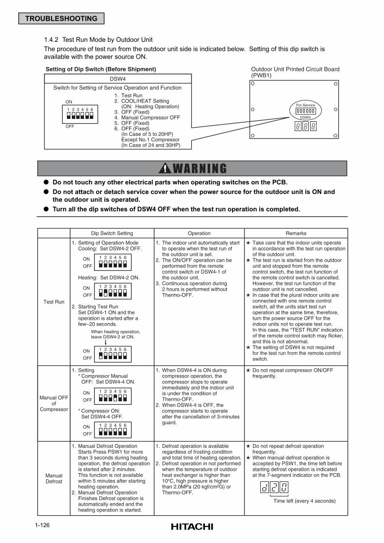
1-126
TROUBLESHOOTING
1.4.2 Test Run Mode by Outdoor Unit
The procedure of test run from the outdoor unit side is indicated below. Setting of this dip switch is
available with the power source ON.
Do not touch any other electrical parts when operating switches on the PCB.
Do not attach or detach service cover when the power source for the outdoor unit is ON and
the outdoor unit is operated.
Turn all the dip switches of DSW4 OFF when the test run operation is completed.
Test Run
RemarksOperationDip Switch Setting
1. Setting of Operation ModeCooling: Set DSW4-2 OFF.
Heating: Set DSW4-2 ON.
2. Starting Test RunSet DSW4-1 ON and theoperation is started after afew~20 seconds.
1. Setting* Compressor Manual
OFF: Set DSW4-4 ON.
* Compressor ON:Set DSW4-4 OFF.
1. Manual Defrost OperationStarts Press PSW1 for morethan 3 seconds during heatingoperation, the defrost operationis started after 2 minutes.This function is not availablewithin 5 minutes after startingheating operation.
2. Manual Defrost OperationFinishes Defrost operation isautomatically ended and theheating operation is started.
1. The indoor unit automatically startto operate when the test run ofthe outdoor unit is set.
2. The ON/OFF operation can beperformed from the remotecontrol switch or DSW4-1 of the outdoor unit.
3. Continuous operation during2 hours is performed withoutThermo-OFF.
1. When DSW4-4 is ON duringcompressor operation, thecompressor stops to operateimmediately and the indoor unitis under the condition ofThermo-OFF.
2. When DSW4-4 is OFF, thecompressor starts to operateafter the cancellation of 3-minutesguard.
1. Defrost operation is availableregardless of frosting conditionand total time of heating operation.
2. Defrost operation in not performedwhen the temperature of outdoorheat exchanger is higher than10oC, high pressure is higherthan 2.0MPa (20 kgf/cm2G) orThermo-OFF.
Take care that the indoor units operatein accordance with the test run operationof the outdoor unit.
The test run is started from the outdoorunit and stopped from the remotecontrol switch, the test run function ofthe remote control switch is cancelled.However, the test run function of theoutdoor unit is not cancelled.
In case that the plural indoor units areconnected with one remote controlswitch, all the units start test runoperation at the same time, therefore,turn the power source OFF for theindoor units not to operate test run.In this case, the "TEST RUN" indicationof the remote control switch may flicker,and this is not abnormal.
The setting of DSW4 is not requiredfor the test run from the remote controlswitch.
Do not repeat compressor ON/OFFfrequently.
Do not repeat defrost operationfrequently.
When manual defrost operation isaccepted by PSW1, the time left beforestarting defrost operation is indicatedat the 7-segment indicator on the PCB.
Manual OFFof
Compressor
ManualDefrost
Time left (every 4 seconds)
When heating operation,leave DSW4-2 at ON.
1 2 3 4 5 6ON
OFF
1 2 3 4 5 6ON
OFF
1 2 3 4 5 6ON
OFF
1 2 3 4 5 6ON
OFF
1 2 3 4 5 6ON
OFF
DSW4
Setting of Dip Switch (Before Shipment)
Switch for Setting of Service Operation and Function1. Test Run2. COOL/HEAT Setting
(ON: Heating Operation)3. OFF (Fixed)4. Manual Compressor OFF5. OFF (Fixed)6. OFF (Fixed)
(In Case of 5 to 20HP)Except No.1 Compressor(In Case of 24 and 30HP)
Outdoor Unit Printed Circuit Board(PWB1)
DSW4
For Service1 2 3 4 5 6
ON
OFF
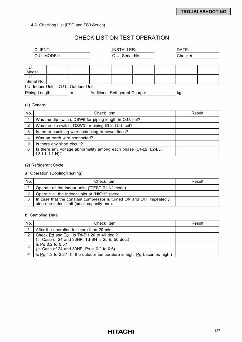
1-127
TROUBLESHOOTING
1.4.3 Checking List (FSG and FS3 Series)
CLIENT: INSTALLER: DATE:
O.U. MODEL: O.U. Serial No.: Checker:
I.U. Indoor Unit, O.U.: Outdoor Unit
Piping Length: m Additional Refrigerant Charge: kg
(1) General
No.
1
2
3
4
5
6
(2) Refrigerant Cycle
a. Operation (Cooling/Heating)
No.
1
2
3
b. Sampling Data
No.
1
2
3
4
Result
Was the dip switch, DSW3 for piping lift in O.U. set?
Is the transmitting wire contacting to power lines?
Was an earth wire connected?
Is there any short circuit?
I.U. Model
I.U. Serial No.
Check Item
Was the dip switch, DSW6 for piping length in O.U. set?
Check Item Result
Is there any voltage abnormality among each phase (L1-L2, L2-L3, L3-L1, L1-N)?
In case that the constant compressor is turned ON and OFF repeatedly, stop one indoor unit (small capacity one).
Operate all the indoor units ("TEST RUN" mode).
Operate all the indoor units at "HIGH" speed.
Is Pd 1.2 to 2.2? (If the outdoor temperature is high, Pd becomes high.)
CHECK LIST ON TEST OPERATION
Check Pd and Td. Is Td-SH 20 to 40 deg.? (In Case of 24 and 30HP, Td-SH is 25 to 50 deg.)
Is Ps 0.2 to 0.5? (In Case of 24 and 30HP, Ps is 0.2 to 0.6)
Check Item Result
After the operation for more than 20 min.
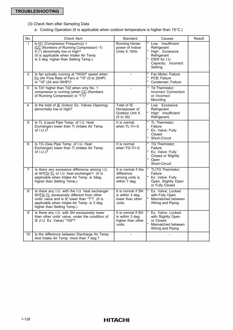
1-128
TROUBLESHOOTING
(3) Check Item after Sampling Data
a. Cooling Operation (It is applicable when outdoor temperature is higher than 15°C.)
No. Check Item Standard Result
1 Is H1 (Compressor Frequency) + (CC (Numbers of Running Compressor) -1) X (*) abnormally low or high? (It is applicable when Intake Air Temp. is 3 deg. higher than Setting Temp.)
Running Horse- power of Indoor Units X 15Hz
*
*
*
Low: InsufficientRefrigerantHigh: ExcessiveRefrigerantDSW for I.U.Capacity; IncorrectSetting
2 Is fan actually running at "HIGH" speed when Fo (Air Flow Rate of Fan) is "15" (5 to 20HP) or "16" (24 and 30HP)?
- ***
Fan Motor; FailurePCB; FailureCondenser; Failure
3 Is Td1 higher than Td2 when only No. 1 compressor is running (when CC (Numbers of Running Compressor) is "1")?
- * Td Thermistor;Incorrect Connectionor IncorrectMounting
4 Is the total of iE (Indoor Ex. Valves Opening) abnormally low or high?
Total of iE: Horsepower of Outdoor Unit X (5 to 30)
*
*
Low: ExcessiveRefrigerantHigh: InsufficientRefrigerant,
5 Is TL (Liquid Pipe Temp. of I.U. Heat Exchanger) lower than Ti (Intake Air Temp. of I.U.)?
It is normal when TL-Ti<-5.
*
*
*
TL Thermistor;FailureEx. Valve; FullyClosedShort-Circuit
6 Is TG (Gas Pipe Temp. of I.U. Heat Exchanger) lower than Ti (Intake Air Temp. of I.U.)?
It is normal when TG-Ti<-5.
*
*
*
TG Thermistor;FailureEx. Valve; FullyClosed or SlightlyOpenShort-Circuit
7 Is there any excessive difference among I.U. at SHTG-TL of I.U. heat exchanger? (It is applicable when Intake Air Temp. is 3deg. higher than Setting Temp.)
It is normal if the difference among units is within 7 deg.
*
*
TL/TG Thermistor;FailureEx. Valve; FullyOpen, Slightly Openor Fully Closed
8 Is there any I.U. with the I.U. heat exchanger SHTG-TL excessively different from other units' value and is iE lower than "7"? (It is applicable when Intake Air Temp. is 3 deg. higher than Setting Temp.)
It is normal if SH is within 3 deg. lower than other units.
*
*
Ex. Valve; Lockedwith Fully OpenMismatched betweenWiring and Piping
9 Is there any I.U. with SH excessively lower than other units' value, under the condition of iE (I.U. Ex. Value) "100"?
It is normal if SH is within 3 deg. higher than other units.
*
*
Ex. Valve; Lockedwith Slightly Openor ClosedMismatched betweenWiring and Piping
10 Is the difference between Discharge Air Temp. And Intake Air Temp. more than 7 deg.?
- -
Causes
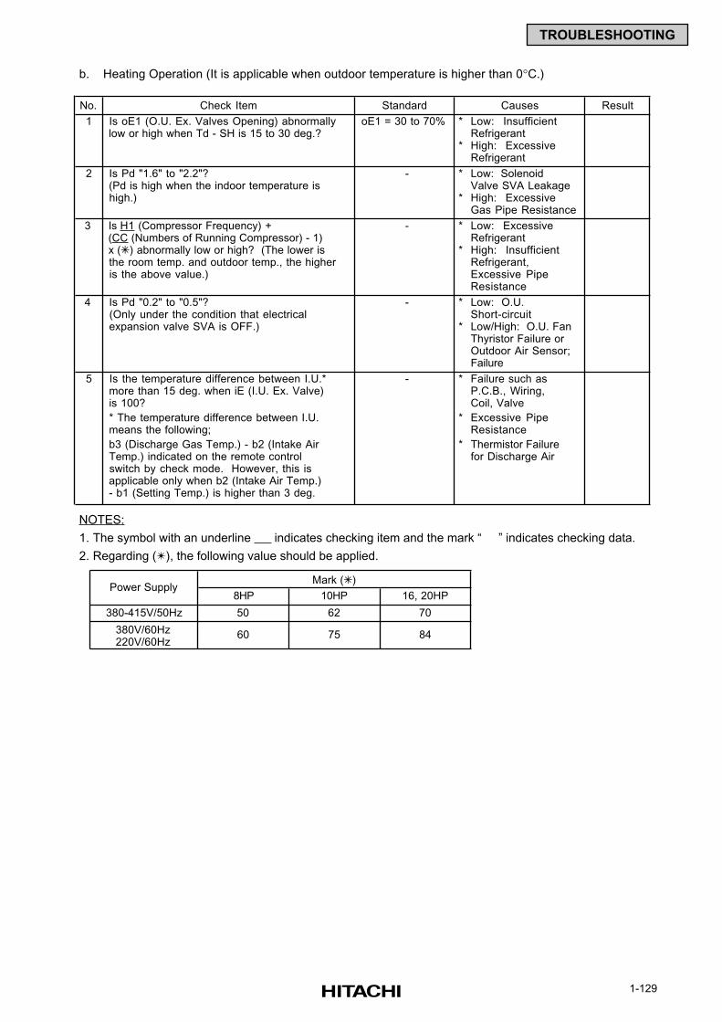
1-129
TROUBLESHOOTING
b. Heating Operation (It is applicable when outdoor temperature is higher than 0°C.)
NOTES:
1. The symbol with an underline indicates checking item and the mark “ ” indicates checking data.
2. Regarding (), the following value should be applied.
No. Check Item Standard Result
1 Is oE1 (O.U. Ex. Valves Opening) abnormally low or high when Td - SH is 15 to 30 deg.?
oE1 = 30 to 70% *
*
Low: InsufficientRefrigerantHigh: ExcessiveRefrigerant
2 Is Pd "1.6" to "2.2"? (Pd is high when the indoor temperature is high.)
- *
*
Low: SolenoidValve SVA LeakageHigh: ExcessiveGas Pipe Resistance
3 Is H1 (Compressor Frequency) + (CC (Numbers of Running Compressor) - 1) x () abnormally low or high? (The lower is the room temp. and outdoor temp., the higher is the above value.)
- *
*
Low: ExcessiveRefrigerantHigh: InsufficientRefrigerant,Excessive PipeResistance
4 Is Pd "0.2" to "0.5"? (Only under the condition that electrical expansion valve SVA is OFF.)
- *
*
Low: O.U.Short-circuitLow/High: O.U. FanThyristor Failure orOutdoor Air Sensor;Failure
5 Is the temperature difference between I.U.* more than 15 deg. when iE (I.U. Ex. Valve) is 100?
- * Failure such asP.C.B., Wiring,Coil, Valve
* The temperature difference between I.U. means the following;
* Excessive PipeResistance
b3 (Discharge Gas Temp.) - b2 (Intake Air Temp.) indicated on the remote control switch by check mode. However, this is applicable only when b2 (Intake Air Temp.) - b1 (Setting Temp.) is higher than 3 deg.
* Thermistor Failurefor Discharge Air
Causes
8HP 10HP 16, 20HP
380-415V/50Hz 50 62 70
380V/60Hz220V/60Hz
60 75 84
Mark ()Power Supply

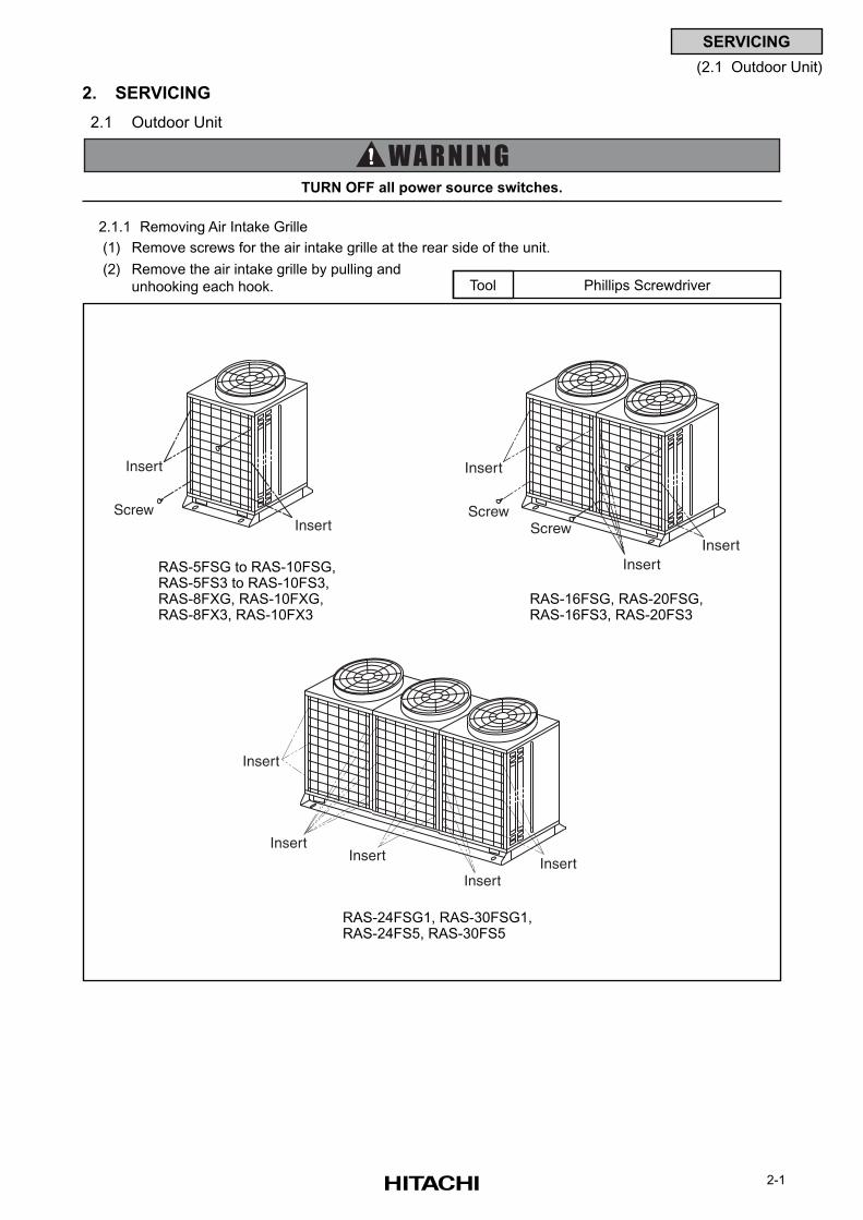
2-1
SERVICING
(2.1 Outdoor Unit)
2. SERVICING
2.1 Outdoor Unit
2.1.1 Removing Air Intake Grille
(1) Remove screws for the air intake grille at the rear side of the unit.
(2) Remove the air intake grille by pulling and
unhooking each hook. Phillips ScrewdriverTool
TURN OFF all power source switches.
Insert
InsertScrew
Insert
InsertInsert
ScrewScrew
Insert
InsertInsert
InsertInsert
RAS-5FSG to RAS-10FSG,RAS-5FS3 to RAS-10FS3,RAS-8FXG, RAS-10FXG,RAS-8FX3, RAS-10FX3
RAS-16FSG, RAS-20FSG,RAS-16FS3, RAS-20FS3
RAS-24FSG1, RAS-30FSG1,RAS-24FS5, RAS-30FS5
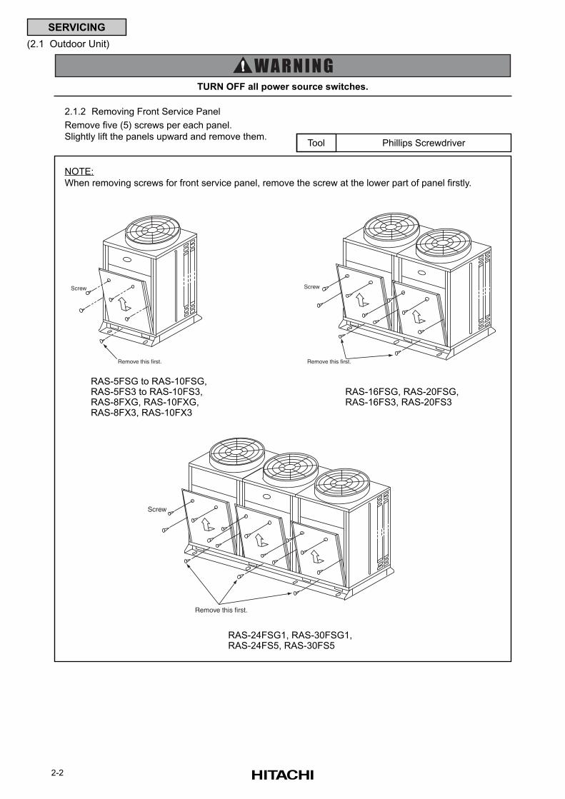
2-2
SERVICING
(2.1 Outdoor Unit)
2.1.2 Removing Front Service Panel
Remove five (5) screws per each panel.
Slightly lift the panels upward and remove them.Phillips ScrewdriverTool
NOTE:
When removing screws for front service panel, remove the screw at the lower part of panel firstly.
Screw
Remove this first.
Screw
Remove this first.
Screw
Remove this first.
TURN OFF all power source switches.
RAS-5FSG to RAS-10FSG,RAS-5FS3 to RAS-10FS3,RAS-8FXG, RAS-10FXG,RAS-8FX3, RAS-10FX3
RAS-16FSG, RAS-20FSG,RAS-16FS3, RAS-20FS3
RAS-24FSG1, RAS-30FSG1,RAS-24FS5, RAS-30FS5
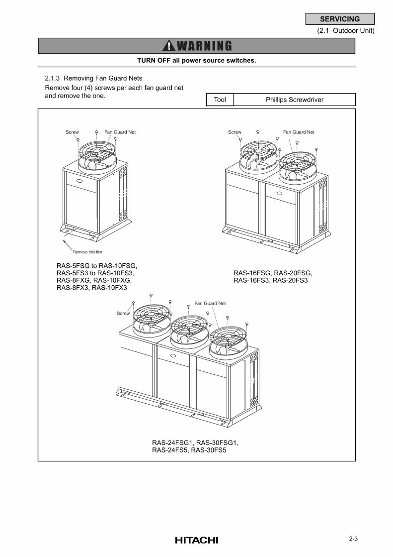
2-3
SERVICING
(2.1 Outdoor Unit)
2.1.3 Removing Fan Guard Nets
Remove four (4) screws per each fan guard net
and remove the one.
TURN OFF all power source switches.
Phillips ScrewdriverTool
RAS-5FSG to RAS-10FSG,RAS-5FS3 to RAS-10FS3,RAS-8FXG, RAS-10FXG,RAS-8FX3, RAS-10FX3
RAS-16FSG, RAS-20FSG,RAS-16FS3, RAS-20FS3
RAS-24FSG1, RAS-30FSG1,RAS-24FS5, RAS-30FS5
Remove this first.
Screw Fan Guard Net Screw Fan Guard Net
Screw
Fan Guard Net
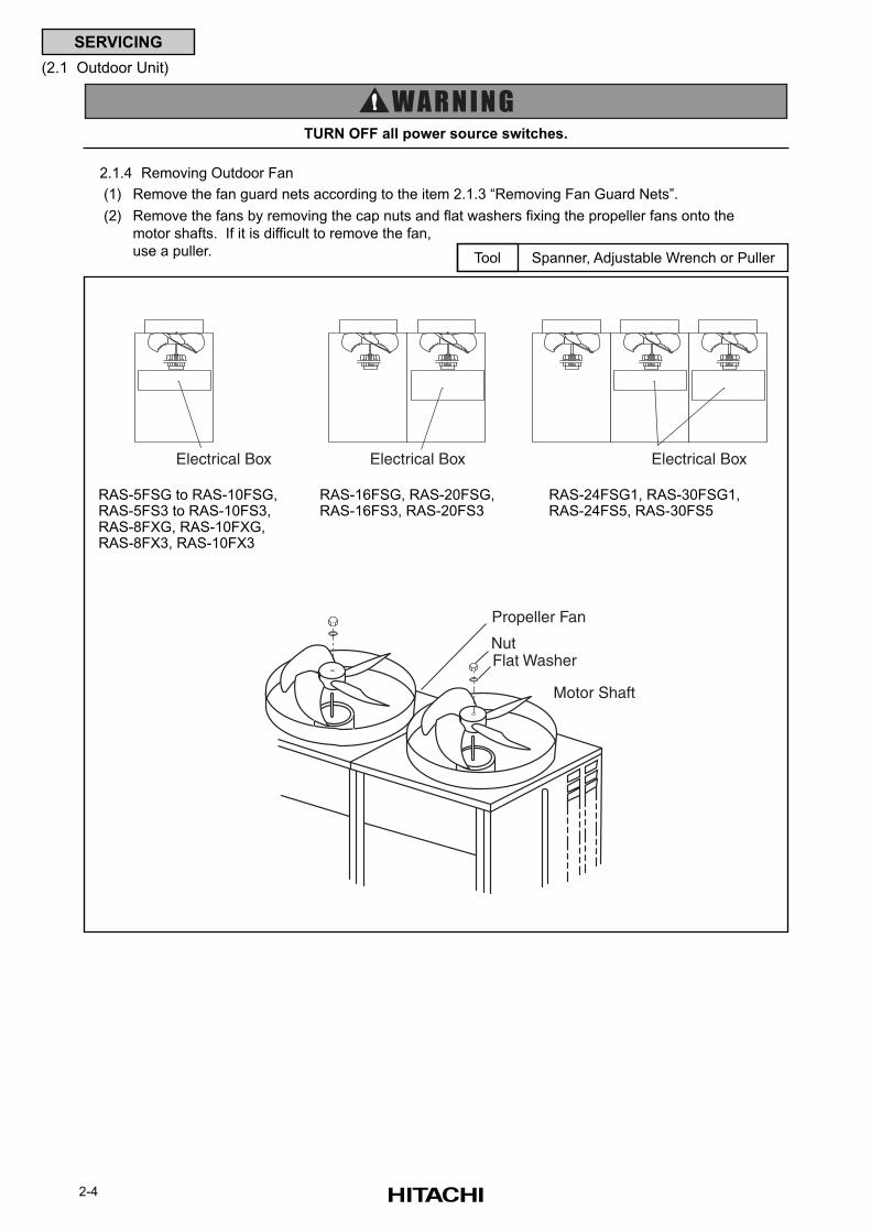
2-4
SERVICING
(2.1 Outdoor Unit)
2.1.4 Removing Outdoor Fan
(1) Remove the fan guard nets according to the item 2.1.3 “Removing Fan Guard Nets”.
(2) Remove the fans by removing the cap nuts and flat washers fixing the propeller fans onto the
motor shafts. If it is difficult to remove the fan,
use a puller.Spanner, Adjustable Wrench or PullerTool
TURN OFF all power source switches.
Electrical Box Electrical Box Electrical Box
Propeller Fan
NutFlat Washer
Motor Shaft
RAS-5FSG to RAS-10FSG,RAS-5FS3 to RAS-10FS3,RAS-8FXG, RAS-10FXG,RAS-8FX3, RAS-10FX3
RAS-16FSG, RAS-20FSG,RAS-16FS3, RAS-20FS3
RAS-24FSG1, RAS-30FSG1,RAS-24FS5, RAS-30FS5
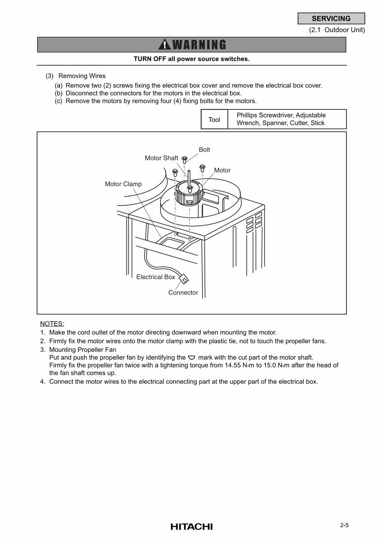
2-5
SERVICING
(2.1 Outdoor Unit)
NOTES:
1. Make the cord outlet of the motor directing downward when mounting the motor.
2. Firmly fix the motor wires onto the motor clamp with the plastic tie, not to touch the propeller fans.
3. Mounting Propeller Fan
Put and push the propeller fan by identifying the mark with the cut part of the motor shaft.
Firmly fix the propeller fan twice with a tightening torque from 14.55 N m to 15.0 Nm after the head of
the fan shaft comes up.
4. Connect the motor wires to the electrical connecting part at the upper part of the electrical box.
(3) Removing Wires
(a) Remove two (2) screws fixing the electrical box cover and remove the electrical box cover.
(b) Disconnect the connectors for the motors in the electrical box.
(c) Remove the motors by removing four (4) fixing bolts for the motors.
TURN OFF all power source switches.
Phillips Screwdriver, Adjustable
Wrench, Spanner, Cutter, StickTool
Bolt
Motor
Motor Shaft
Motor Clamp
Electrical Box
Connector
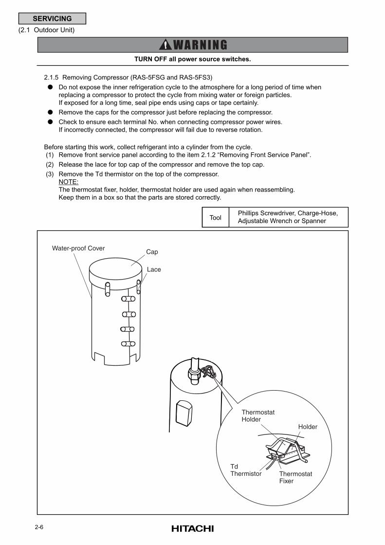
2-6
SERVICING
(2.1 Outdoor Unit)
2.1.5 Removing Compressor (RAS-5FSG and RAS-5FS3)
Do not expose the inner refrigeration cycle to the atmosphere for a long period of time when
replacing a compressor to protect the cycle from mixing water or foreign particles.
If exposed for a long time, seal pipe ends using caps or tape certainly.
Remove the caps for the compressor just before replacing the compressor.
Check to ensure each terminal No. when connecting compressor power wires.
If incorrectly connected, the compressor will fail due to reverse rotation.
Before starting this work, collect refrigerant into a cylinder from the cycle.
(1) Remove front service panel according to the item 2.1.2 “Removing Front Service Panel”.
(2) Release the lace for top cap of the compressor and remove the top cap.
(3) Remove the Td thermistor on the top of the compressor.
NOTE:
The thermostat fixer, holder, thermostat holder are used again when reassembling.
Keep them in a box so that the parts are stored correctly.
TURN OFF all power source switches.
Phillips Screwdriver, Charge-Hose,
Adjustable Wrench or SpannerTool
Cap
Lace
Water-proof Cover
Thermostat Holder
Holder
Td Thermistor Thermostat
Fixer
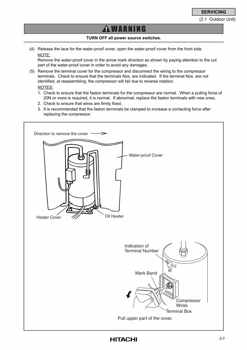
2-7
SERVICING
(2.1 Outdoor Unit)
(4) Release the lace for the water-proof cover, open the water-proof cover from the front side.
NOTE:
Remove the water-proof cover in the arrow mark direction as shown by paying attention to the cut
part of the water-proof cover in order to avoid any damages.
(5) Remove the terminal cover for the compressor and disconnect the wiring to the compressor
terminals. Check to ensure that the terminals Nos. are indicated. If the terminal Nos. are not
identified, at reassembling, the compressor will fail due to reverse rotation.
NOTES:
1. Check to ensure that the faston terminals for the compressor are normal. When a pulling force of
20N or more is required, it is normal. If abnormal, replace the faston terminals with new ones.
2. Check to ensure that wires are firmly fixed.
3. It is recommended that the faston terminals be clamped to increase a contacting force after
replacing the compressor.
TURN OFF all power source switches.
Water-proof Cover
Direction to remove the cover
Heater Cover Oil Heater
UW
V
Pull upper part of the cover.
Terminal Box
CompressorWires
Indication ofTerminal Number
Mark Band
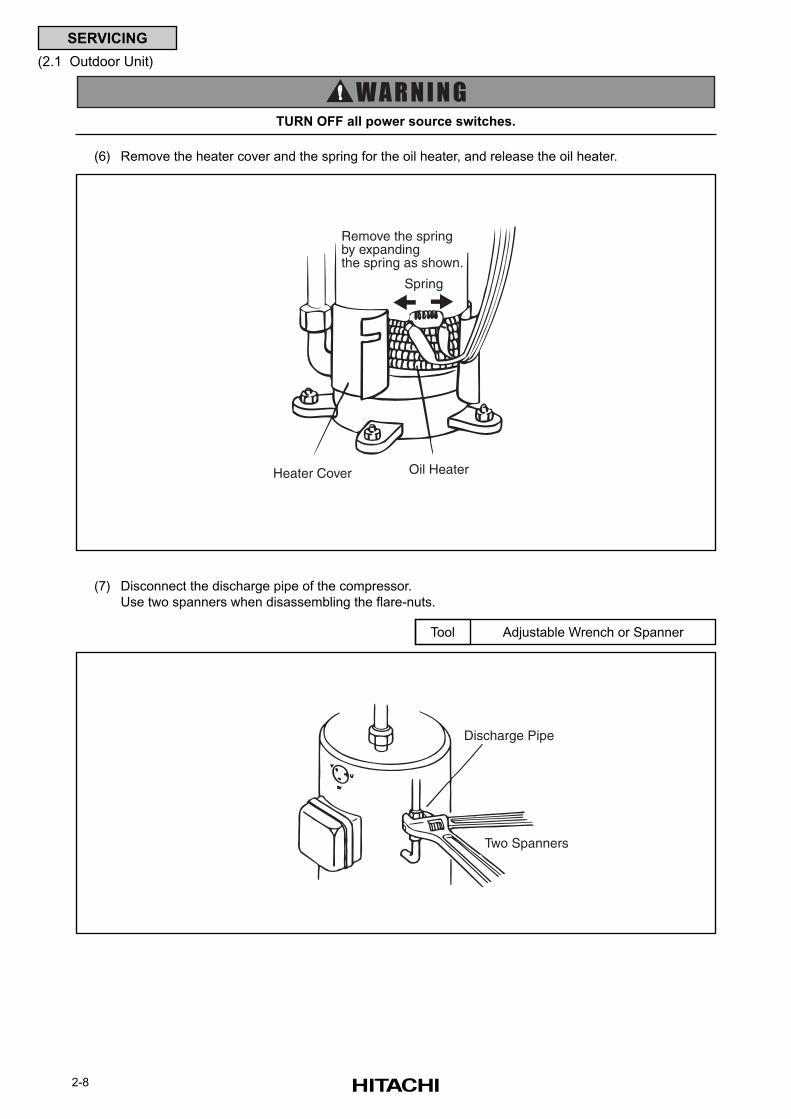
2-8
SERVICING
(2.1 Outdoor Unit)
(6) Remove the heater cover and the spring for the oil heater, and release the oil heater.
TURN OFF all power source switches.
(7) Disconnect the discharge pipe of the compressor.
Use two spanners when disassembling the flare-nuts.
Adjustable Wrench or SpannerTool
Spring
Remove the springby expandingthe spring as shown.
Oil HeaterHeater Cover
Discharge Pipe
Two Spanners
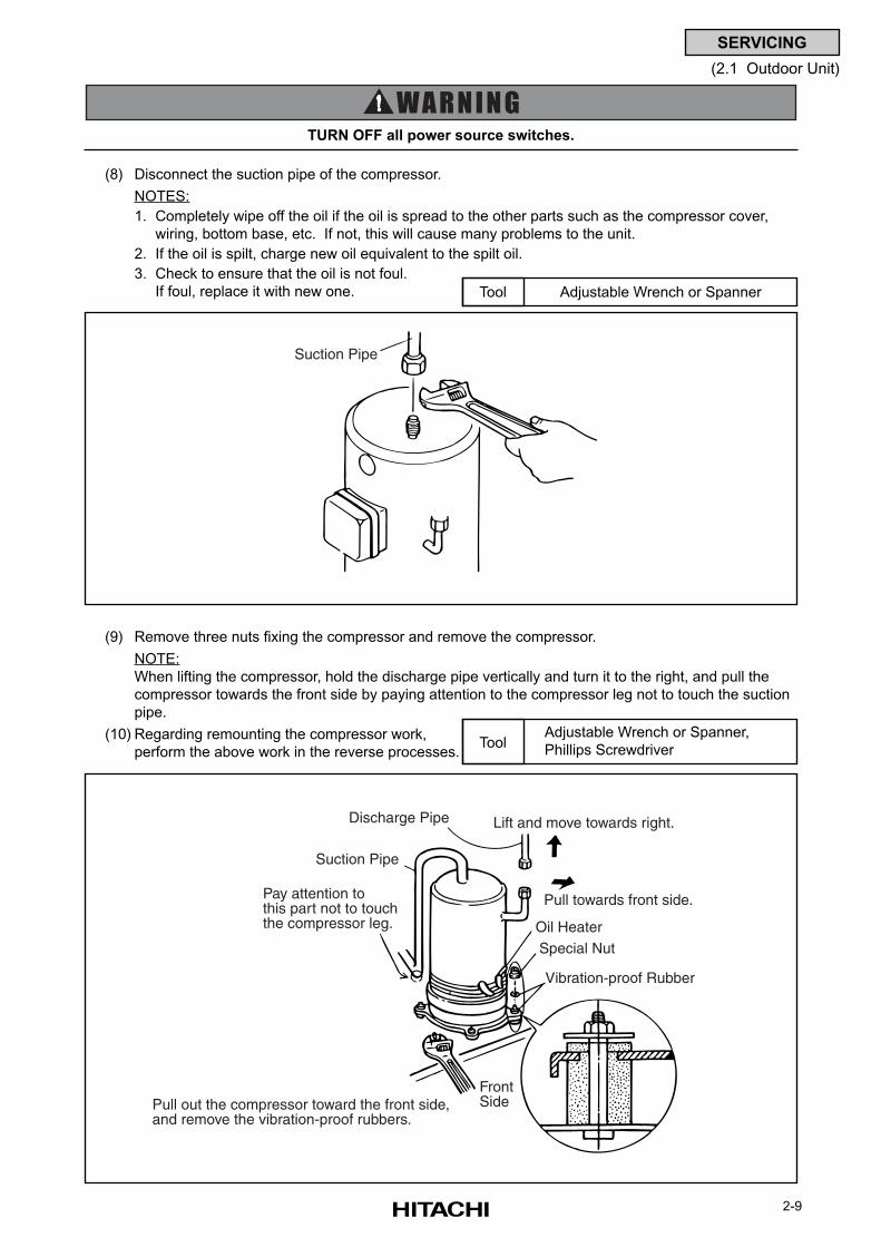
2-9
SERVICING
(2.1 Outdoor Unit)
(8) Disconnect the suction pipe of the compressor.
NOTES:
1. Completely wipe off the oil if the oil is spread to the other parts such as the compressor cover,
wiring, bottom base, etc. If not, this will cause many problems to the unit.
2. If the oil is spilt, charge new oil equivalent to the spilt oil.
3. Check to ensure that the oil is not foul.
If foul, replace it with new one.
TURN OFF all power source switches.
Adjustable Wrench or SpannerTool
Adjustable Wrench or Spanner,
Phillips ScrewdriverTool
(9) Remove three nuts fixing the compressor and remove the compressor.
NOTE:
When lifting the compressor, hold the discharge pipe vertically and turn it to the right, and pull the
compressor towards the front side by paying attention to the compressor leg not to touch the suction
pipe.
(10) Regarding remounting the compressor work,
perform the above work in the reverse processes.
Suction Pipe
Discharge Pipe Lift and move towards right.
Pull towards front side.
Oil HeaterSpecial Nut
Vibration-proof Rubber
Suction Pipe
Pay attention to this part not to touchthe compressor leg.
FrontSidePull out the compressor toward the front side,
and remove the vibration-proof rubbers.
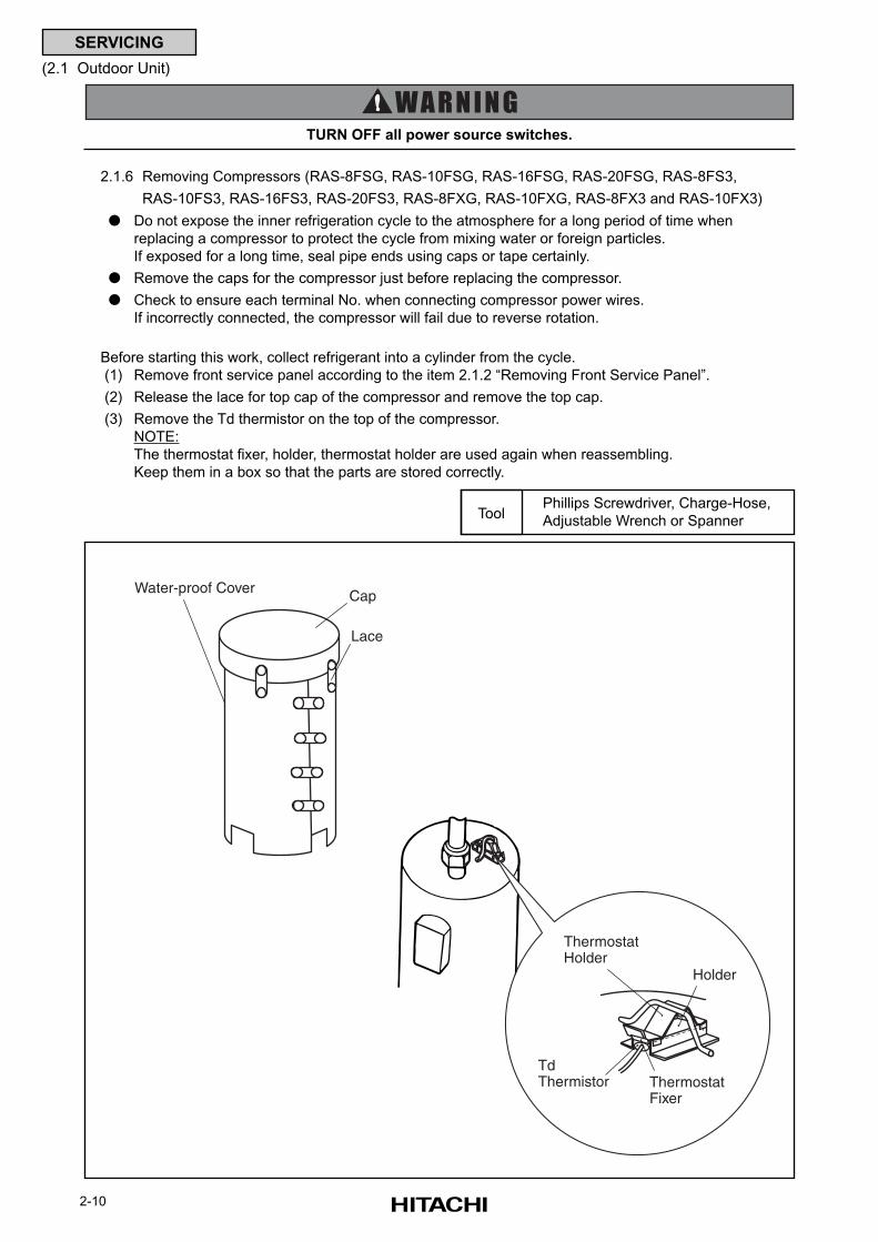
2-10
SERVICING
(2.1 Outdoor Unit)
2.1.6 Removing Compressors (RAS-8FSG, RAS-10FSG, RAS-16FSG, RAS-20FSG, RAS-8FS3,
RAS-10FS3, RAS-16FS3, RAS-20FS3, RAS-8FXG, RAS-10FXG, RAS-8FX3 and RAS-10FX3)
Do not expose the inner refrigeration cycle to the atmosphere for a long period of time when
replacing a compressor to protect the cycle from mixing water or foreign particles.
If exposed for a long time, seal pipe ends using caps or tape certainly.
Remove the caps for the compressor just before replacing the compressor.
Check to ensure each terminal No. when connecting compressor power wires.
If incorrectly connected, the compressor will fail due to reverse rotation.
Before starting this work, collect refrigerant into a cylinder from the cycle.
(1) Remove front service panel according to the item 2.1.2 “Removing Front Service Panel”.
(2) Release the lace for top cap of the compressor and remove the top cap.
(3) Remove the Td thermistor on the top of the compressor.
NOTE:
The thermostat fixer, holder, thermostat holder are used again when reassembling.
Keep them in a box so that the parts are stored correctly.
TURN OFF all power source switches.
Phillips Screwdriver, Charge-Hose,
Adjustable Wrench or SpannerTool
Cap
Lace
Water-proof Cover
Thermostat Holder
Holder
Td Thermistor Thermostat
Fixer
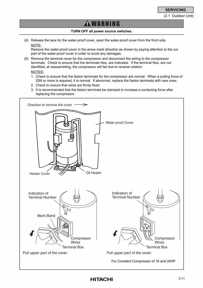
2-11
SERVICING
(2.1 Outdoor Unit)
(4) Release the lace for the water-proof cover, open the water-proof cover from the front side.
NOTE:
Remove the water-proof cover in the arrow mark direction as shown by paying attention to the cut
part of the water-proof cover in order to avoid any damages.
(5) Remove the terminal cover for the compressor and disconnect the wiring to the compressor
terminals. Check to ensure that the terminals Nos. are indicated. If the terminal Nos. are not
identified, at reassembling, the compressor will fail due to reverse rotation.
NOTES:
1. Check to ensure that the faston terminals for the compressor are normal. When a pulling force of
20N or more is required, it is normal. If abnormal, replace the faston terminals with new ones.
2. Check to ensure that wires are firmly fixed.
3. It is recommended that the faston terminals be clamped to increase a contacting force after
replacing the compressor.
TURN OFF all power source switches.
Water-proof Cover
Direction to remove the cover
Heater Cover Oil Heater
UW
V
Pull upper part of the cover.
Terminal Box
CompressorWires
Indication ofTerminal Number
Mark Band
UW
V
Pull upper part of the cover.
Terminal Box
CompressorWires
Indication ofTerminal Number
For Constant Compressor of 16 and 20HP
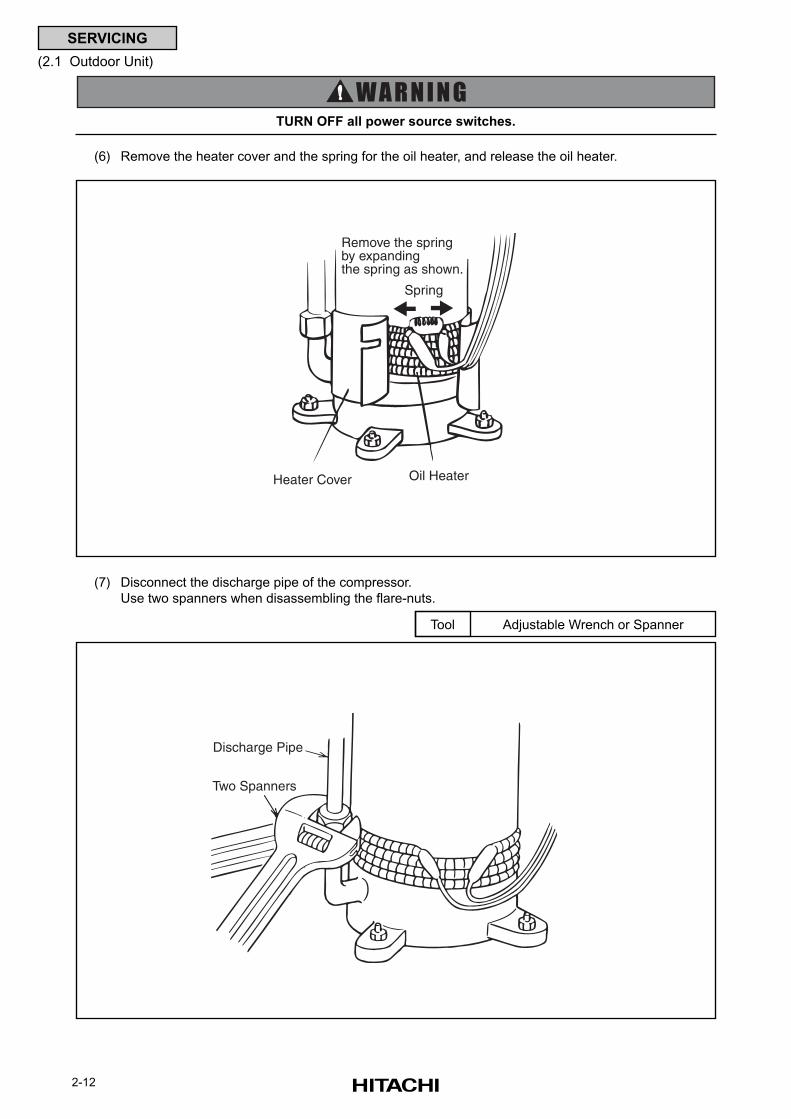
2-12
SERVICING
(2.1 Outdoor Unit)
(7) Disconnect the discharge pipe of the compressor.
Use two spanners when disassembling the flare-nuts.
Adjustable Wrench or SpannerTool
(6) Remove the heater cover and the spring for the oil heater, and release the oil heater.
TURN OFF all power source switches.
Spring
Remove the springby expandingthe spring as shown.
Oil HeaterHeater Cover
Discharge Pipe
Two Spanners
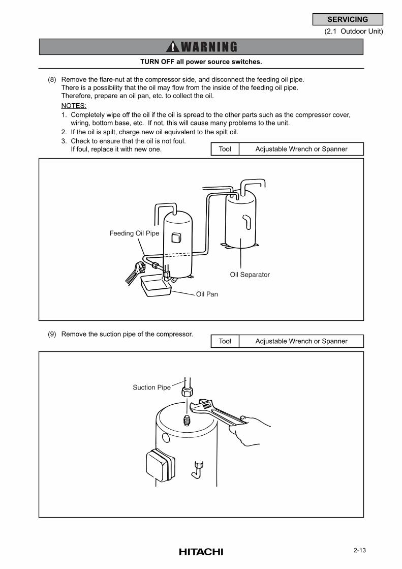
2-13
SERVICING
(2.1 Outdoor Unit)
(8) Remove the flare-nut at the compressor side, and disconnect the feeding oil pipe.
There is a possibility that the oil may flow from the inside of the feeding oil pipe.
Therefore, prepare an oil pan, etc. to collect the oil.
NOTES:
1. Completely wipe off the oil if the oil is spread to the other parts such as the compressor cover,
wiring, bottom base, etc. If not, this will cause many problems to the unit.
2. If the oil is spilt, charge new oil equivalent to the spilt oil.
3. Check to ensure that the oil is not foul.
If foul, replace it with new one. Adjustable Wrench or SpannerTool
TURN OFF all power source switches.
Feeding Oil Pipe
Oil Pan
Oil Separator
(9) Remove the suction pipe of the compressor.Adjustable Wrench or SpannerTool
Suction Pipe
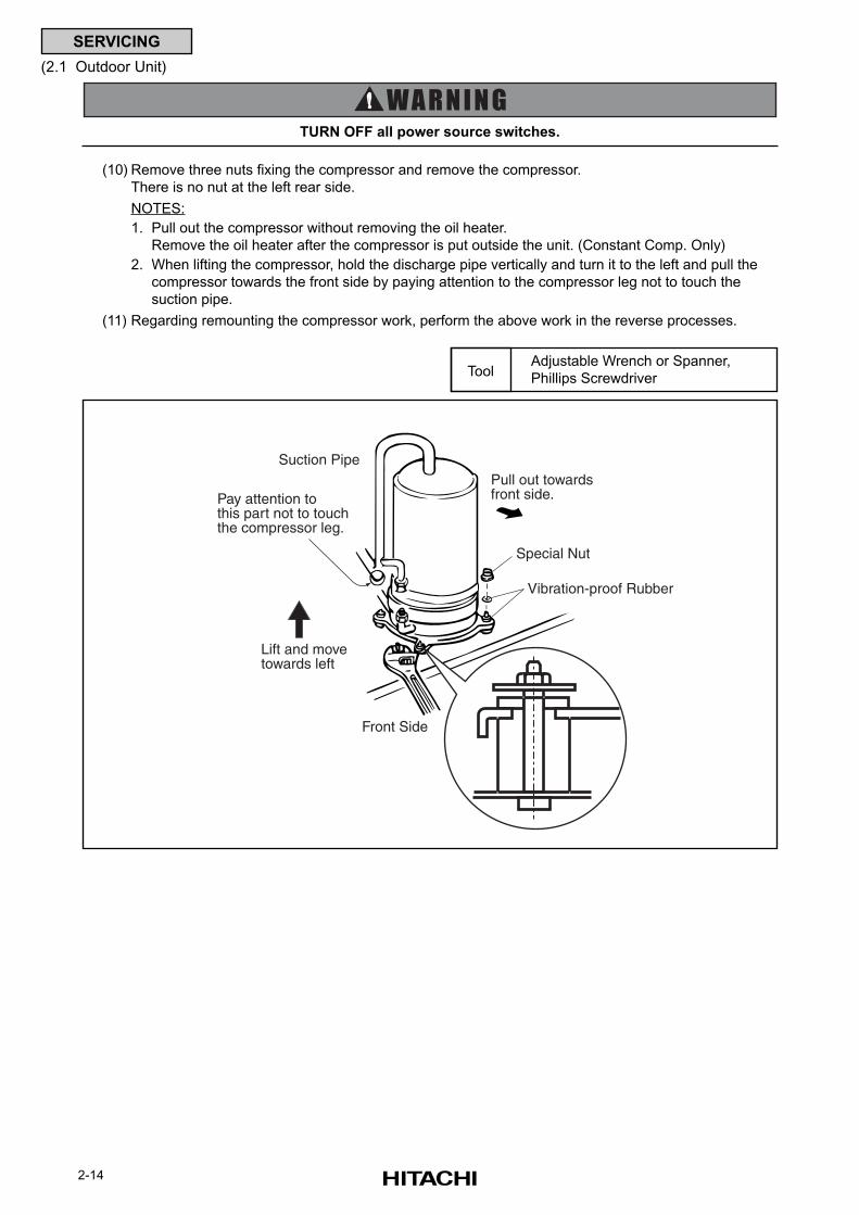
2-14
SERVICING
(2.1 Outdoor Unit)
TURN OFF all power source switches.
Adjustable Wrench or Spanner,
Phillips ScrewdriverTool
(10) Remove three nuts fixing the compressor and remove the compressor.
There is no nut at the left rear side.
NOTES:
1. Pull out the compressor without removing the oil heater.
Remove the oil heater after the compressor is put outside the unit. (Constant Comp. Only)
2. When lifting the compressor, hold the discharge pipe vertically and turn it to the left and pull the
compressor towards the front side by paying attention to the compressor leg not to touch the
suction pipe.
(11) Regarding remounting the compressor work, perform the above work in the reverse processes.
Front Side
Special Nut
Lift and move towards left
Pull out towardsfront side.
Vibration-proof Rubber
Suction Pipe
Pay attention to this part not to touch the compressor leg.
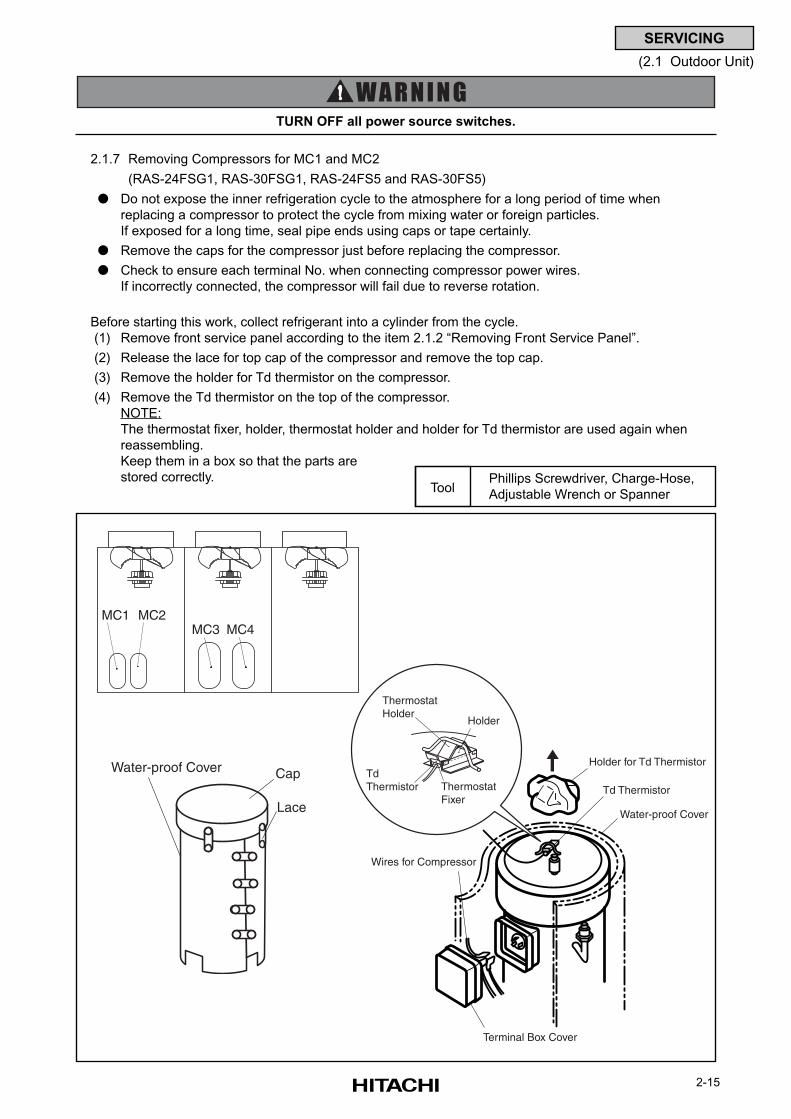
2-15
SERVICING
(2.1 Outdoor Unit)
2.1.7 Removing Compressors for MC1 and MC2
(RAS-24FSG1, RAS-30FSG1, RAS-24FS5 and RAS-30FS5)
Do not expose the inner refrigeration cycle to the atmosphere for a long period of time when
replacing a compressor to protect the cycle from mixing water or foreign particles.
If exposed for a long time, seal pipe ends using caps or tape certainly.
Remove the caps for the compressor just before replacing the compressor.
Check to ensure each terminal No. when connecting compressor power wires.
If incorrectly connected, the compressor will fail due to reverse rotation.
Before starting this work, collect refrigerant into a cylinder from the cycle.
(1) Remove front service panel according to the item 2.1.2 “Removing Front Service Panel”.
(2) Release the lace for top cap of the compressor and remove the top cap.
(3) Remove the holder for Td thermistor on the compressor.
(4) Remove the Td thermistor on the top of the compressor.
NOTE:
The thermostat fixer, holder, thermostat holder and holder for Td thermistor are used again when
reassembling.
Keep them in a box so that the parts are
stored correctly.
TURN OFF all power source switches.
Phillips Screwdriver, Charge-Hose,
Adjustable Wrench or SpannerTool
Cap
Lace
Water-proof Cover Holder for Td Thermistor
Water-proof Cover
Td Thermistor
Wires for Compressor
Terminal Box Cover
Thermostat Holder
Holder
Td Thermistor Thermostat
Fixer
MC1 MC2MC3 MC4
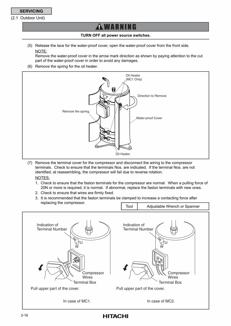
2-16
SERVICING
(2.1 Outdoor Unit)
(5) Release the lace for the water-proof cover, open the water-proof cover from the front side.
NOTE:
Remove the water-proof cover in the arrow mark direction as shown by paying attention to the cut
part of the water-proof cover in order to avoid any damages.
(6) Remove the spring for the oil heater.
TURN OFF all power source switches.
(7) Remove the terminal cover for the compressor and disconnect the wiring to the compressor
terminals. Check to ensure that the terminals Nos. are indicated. If the terminal Nos. are not
identified, at reassembling, the compressor will fail due to reverse rotation.
NOTES:
1. Check to ensure that the faston terminals for the compressor are normal. When a pulling force of
20N or more is required, it is normal. If abnormal, replace the faston terminals with new ones.
2. Check to ensure that wires are firmly fixed.
3. It is recommended that the faston terminals be clamped to increase a contacting force after
replacing the compressor.Adjustable Wrench or SpannerTool
Oil Heater(MC1 Only)
Water-proof Cover
Direction to Remove
Oil Heater
Remove the spring.
UW
VU
W
V
In case of MC1. In case of MC2.
Pull upper part of the cover.
Terminal Box
CompressorWires
Pull upper part of the cover.
Terminal Box
CompressorWires
Indication ofTerminal Number
Indication ofTerminal Number
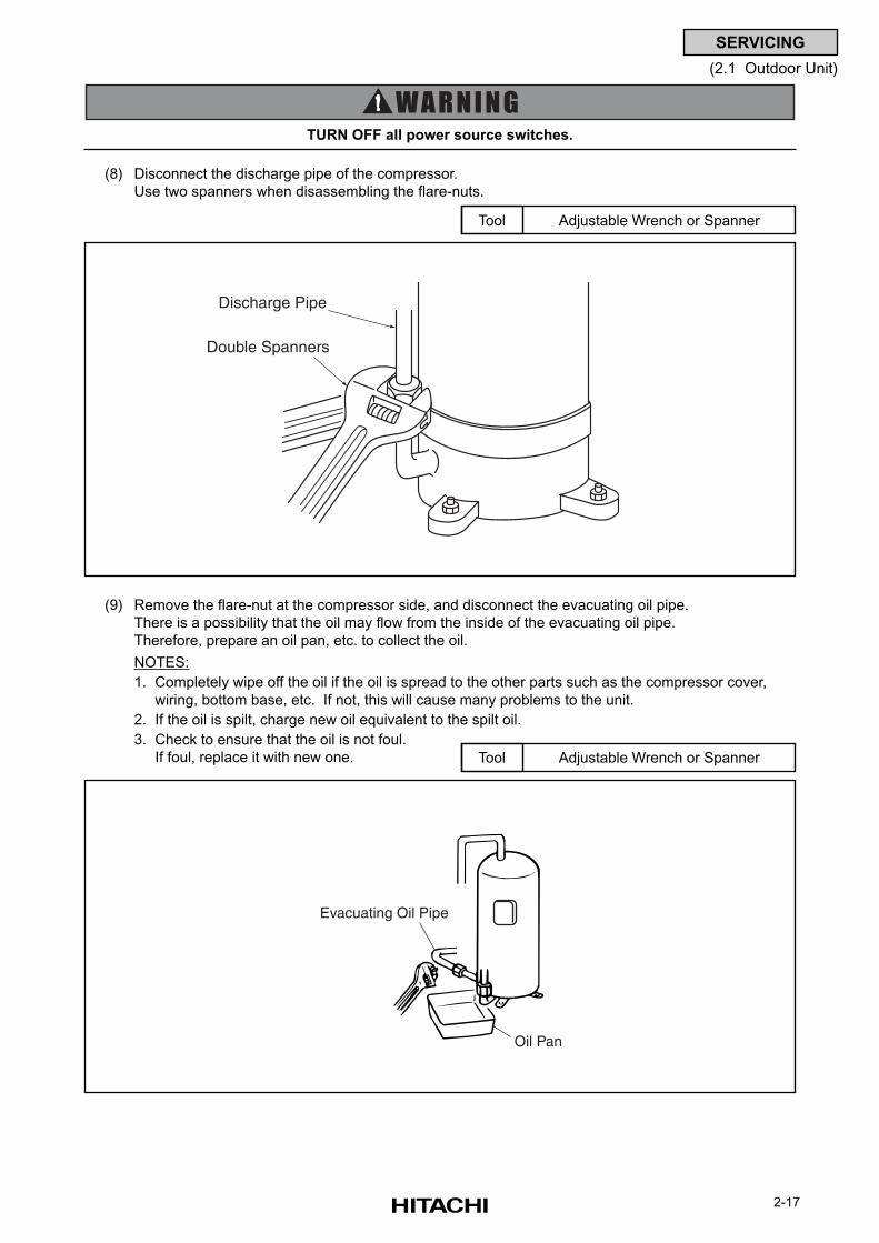
2-17
SERVICING
(2.1 Outdoor Unit)
(9) Remove the flare-nut at the compressor side, and disconnect the evacuating oil pipe.
There is a possibility that the oil may flow from the inside of the evacuating oil pipe.
Therefore, prepare an oil pan, etc. to collect the oil.
NOTES:
1. Completely wipe off the oil if the oil is spread to the other parts such as the compressor cover,
wiring, bottom base, etc. If not, this will cause many problems to the unit.
2. If the oil is spilt, charge new oil equivalent to the spilt oil.
3. Check to ensure that the oil is not foul.
If foul, replace it with new one. Adjustable Wrench or SpannerTool
TURN OFF all power source switches.
(8) Disconnect the discharge pipe of the compressor.
Use two spanners when disassembling the flare-nuts.
Adjustable Wrench or SpannerTool
Discharge Pipe
Double Spanners
Oil Pan
Evacuating Oil Pipe
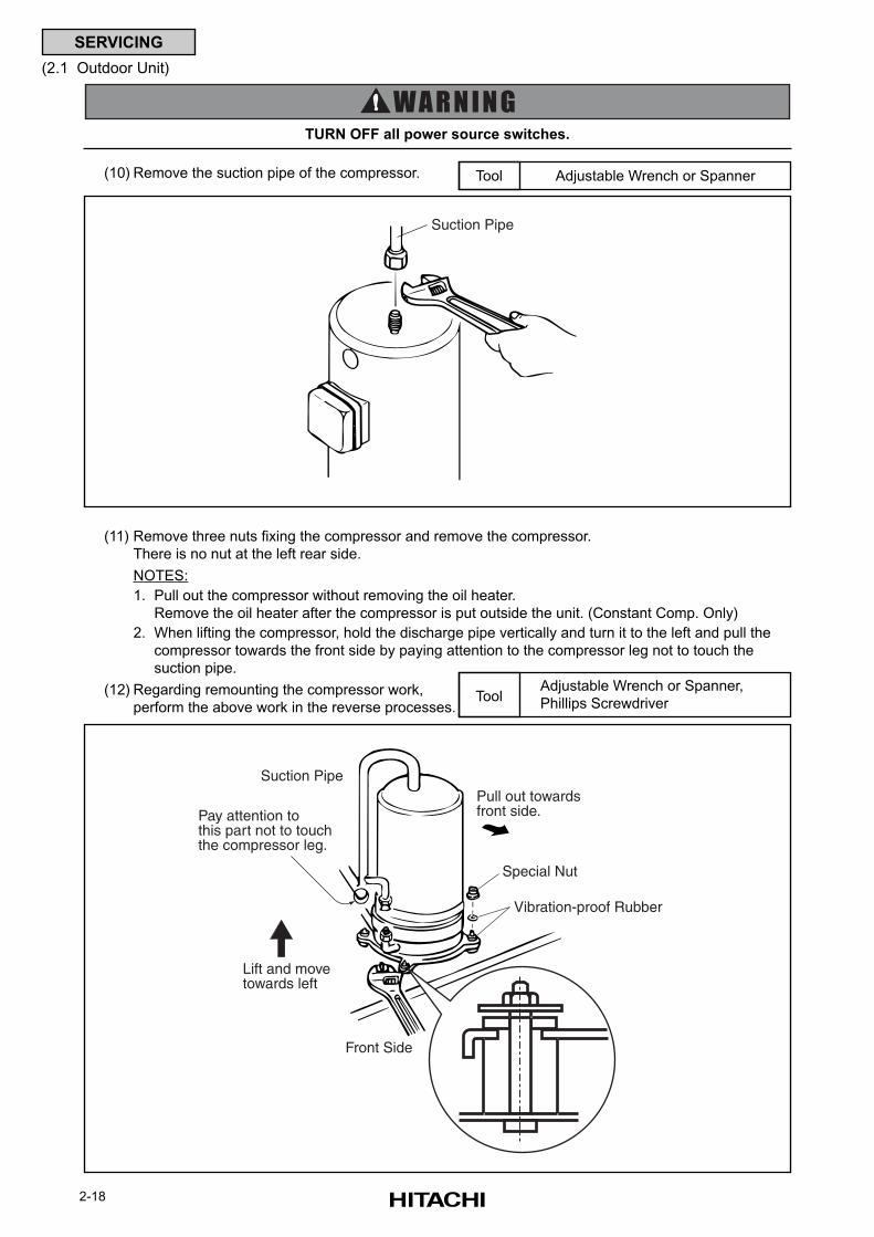
2-18
SERVICING
(2.1 Outdoor Unit)
TURN OFF all power source switches.
Adjustable Wrench or Spanner,
Phillips ScrewdriverTool
(11) Remove three nuts fixing the compressor and remove the compressor.
There is no nut at the left rear side.
NOTES:
1. Pull out the compressor without removing the oil heater.
Remove the oil heater after the compressor is put outside the unit. (Constant Comp. Only)
2. When lifting the compressor, hold the discharge pipe vertically and turn it to the left and pull the
compressor towards the front side by paying attention to the compressor leg not to touch the
suction pipe.
(12) Regarding remounting the compressor work,
perform the above work in the reverse processes.
(10) Remove the suction pipe of the compressor. Adjustable Wrench or SpannerTool
Suction Pipe
Front Side
Special Nut
Lift and move towards left
Pull out towardsfront side.
Vibration-proof Rubber
Suction Pipe
Pay attention to this part not to touch the compressor leg.
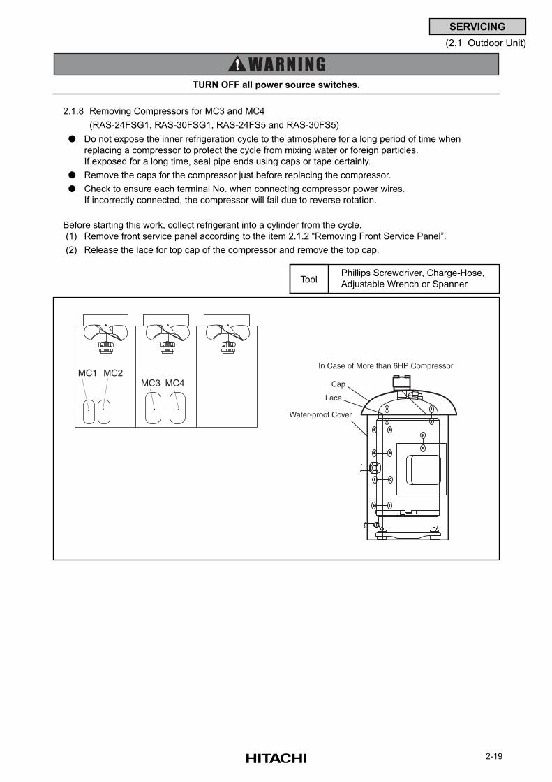
2-19
SERVICING
(2.1 Outdoor Unit)
2.1.8 Removing Compressors for MC3 and MC4
(RAS-24FSG1, RAS-30FSG1, RAS-24FS5 and RAS-30FS5)
Do not expose the inner refrigeration cycle to the atmosphere for a long period of time when
replacing a compressor to protect the cycle from mixing water or foreign particles.
If exposed for a long time, seal pipe ends using caps or tape certainly.
Remove the caps for the compressor just before replacing the compressor.
Check to ensure each terminal No. when connecting compressor power wires.
If incorrectly connected, the compressor will fail due to reverse rotation.
Before starting this work, collect refrigerant into a cylinder from the cycle.
(1) Remove front service panel according to the item 2.1.2 “Removing Front Service Panel”.
(2) Release the lace for top cap of the compressor and remove the top cap.
TURN OFF all power source switches.
Phillips Screwdriver, Charge-Hose,
Adjustable Wrench or SpannerTool
MC1 MC2MC3 MC4
Water-proof Cover
Cap
Lace
In Case of More than 6HP Compressor
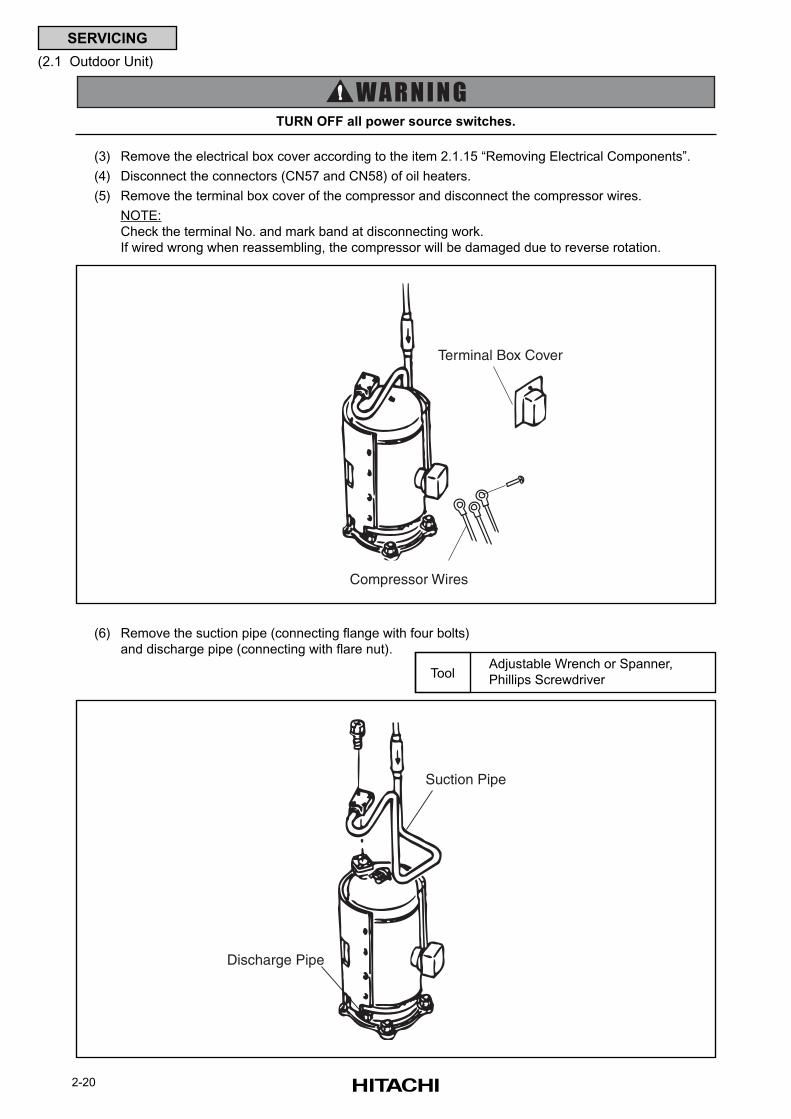
2-20
SERVICING
(2.1 Outdoor Unit)
(3) Remove the electrical box cover according to the item 2.1.15 “Removing Electrical Components”.
(4) Disconnect the connectors (CN57 and CN58) of oil heaters.
(5) Remove the terminal box cover of the compressor and disconnect the compressor wires.
NOTE:
Check the terminal No. and mark band at disconnecting work.
If wired wrong when reassembling, the compressor will be damaged due to reverse rotation.
TURN OFF all power source switches.
(6) Remove the suction pipe (connecting flange with four bolts)
and discharge pipe (connecting with flare nut).Adjustable Wrench or Spanner,
Phillips ScrewdriverTool
Suction Pipe
Discharge Pipe
Terminal Box Cover
Compressor Wires
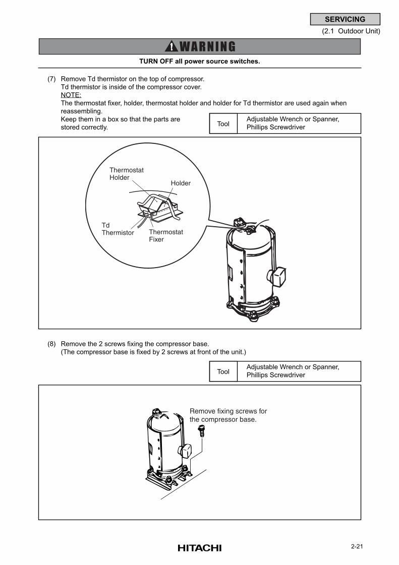
2-21
SERVICING
(2.1 Outdoor Unit)
(7) Remove Td thermistor on the top of compressor.
Td thermistor is inside of the compressor cover.
NOTE:
The thermostat fixer, holder, thermostat holder and holder for Td thermistor are used again when
reassembling.
Keep them in a box so that the parts are
stored correctly.
Adjustable Wrench or Spanner,
Phillips ScrewdriverTool
TURN OFF all power source switches.
(8) Remove the 2 screws fixing the compressor base.
(The compressor base is fixed by 2 screws at front of the unit.)
Adjustable Wrench or Spanner,
Phillips ScrewdriverTool
Remove fixing screws forthe compressor base.
Thermostat Holder
Holder
Td Thermistor Thermostat
Fixer
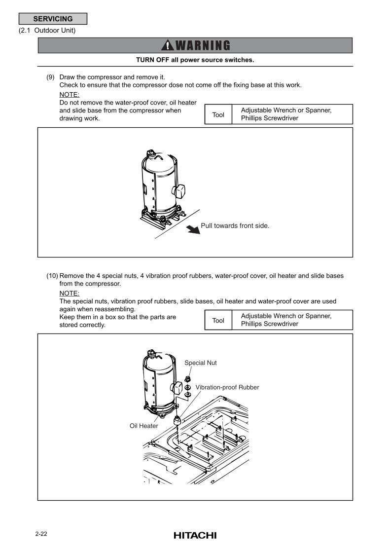
2-22
SERVICING
(2.1 Outdoor Unit)
TURN OFF all power source switches.
(9) Draw the compressor and remove it.
Check to ensure that the compressor dose not come off the fixing base at this work.
NOTE:
Do not remove the water-proof cover, oil heater
and slide base from the compressor when
drawing work.
Adjustable Wrench or Spanner,
Phillips ScrewdriverTool
(10) Remove the 4 special nuts, 4 vibration proof rubbers, water-proof cover, oil heater and slide bases
from the compressor.
NOTE:
The special nuts, vibration proof rubbers, slide bases, oil heater and water-proof cover are used
again when reassembling.
Keep them in a box so that the parts are
stored correctly.
Adjustable Wrench or Spanner,
Phillips ScrewdriverTool
Pull towards front side.
Special Nut
Vibration-proof Rubber
Oil Heater
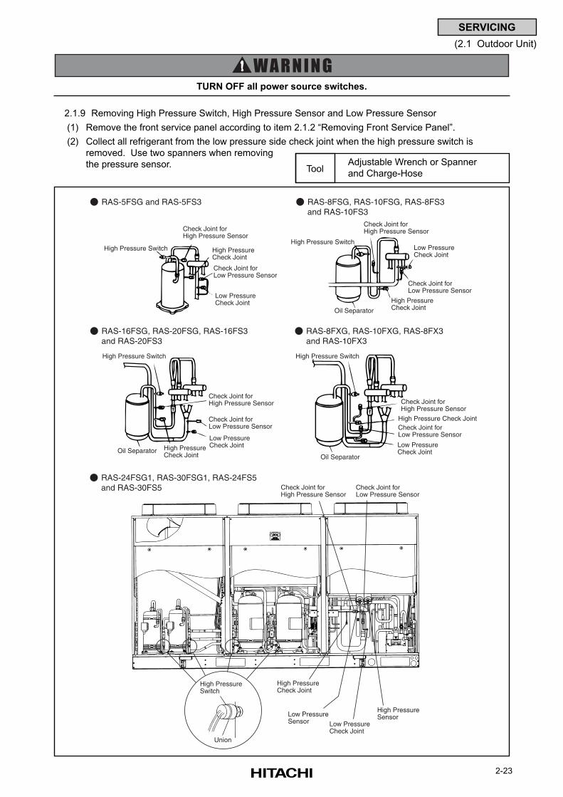
2-23
SERVICING
(2.1 Outdoor Unit)
2.1.9 Removing High Pressure Switch, High Pressure Sensor and Low Pressure Sensor
(1) Remove the front service panel according to item 2.1.2 “Removing Front Service Panel”.
(2) Collect all refrigerant from the low pressure side check joint when the high pressure switch is
removed. Use two spanners when removing
the pressure sensor.
TURN OFF all power source switches.
Adjustable Wrench or Spanner
and Charge-HoseTool
RAS-5FSG and RAS-5FS3 RAS-8FSG, RAS-10FSG, RAS-8FS3and RAS-10FS3
RAS-16FSG, RAS-20FSG, RAS-16FS3and RAS-20FS3
RAS-24FSG1, RAS-30FSG1, RAS-24FS5 and RAS-30FS5
RAS-8FXG, RAS-10FXG, RAS-8FX3and RAS-10FX3
High Pressure SwitchHigh Pressure Switch
High Pressure Switch High Pressure Switch
High PressureCheck Joint
High PressureCheck Joint
High PressureCheck Joint
High Pressure Check Joint
Check Joint forHigh Pressure Sensor
Check Joint forHigh Pressure Sensor
Check Joint forLow Pressure Sensor
Check Joint forLow Pressure Sensor
Check Joint forLow Pressure Sensor Check Joint for
Low Pressure Sensor
Low PressureCheck Joint
Check Joint forHigh Pressure Sensor Check Joint for
High Pressure Sensor
High PressureCheck Joint
Low Pressure Check Joint
Low Pressure Check Joint
Low Pressure Check Joint Low Pressure
Check JointOil Separator
Oil Separator
Oil Separator
Low PressureSensor
High PressureSensor
High PressureSwitch
Union
Check Joint forLow Pressure Sensor
Check Joint forHigh Pressure Sensor
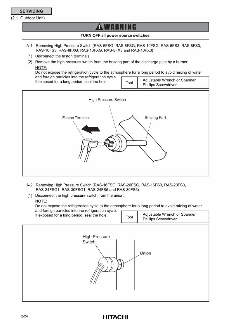
2-24
SERVICING
(2.1 Outdoor Unit)
A-1. Removing High Pressure Switch (RAS-5FSG, RAS-8FSG, RAS-10FSG, RAS-5FS3, RAS-8FS3,
RAS-10FS3, RAS-8FXG, RAS-10FXG, RAS-8FX3 and RAS-10FX3)
(1) Disconnect the faston terminals.
(2) Remove the high pressure switch from the brazing part of the discharge pipe by a burner.
NOTE:
Do not expose the refrigeration cycle to the atmosphere for a long period to avoid mixing of water
and foreign particles into the refrigeration cycle.
If exposed for a long period, seal the hole.
TURN OFF all power source switches.
Adjustable Wrench or Spanner,
Phillips ScrewdriverTool
A-2. Removing High Pressure Switch (RAS-16FSG, RAS-20FSG, RAS-16FS3, RAS-20FS3,
RAS-24FSG1, RAS-30FSG1, RAS-24FS5 and RAS-30FS5)
(1) Disconnect the high pressure switch from the union.
NOTE:
Do not expose the refrigeration cycle to the atmosphere for a long period to avoid mixing of water
and foreign particles into the refrigeration cycle.
If exposed for a long period, seal the hole. Adjustable Wrench or Spanner,
Phillips ScrewdriverTool
High Pressure Switch
Faston Terminal Brazing Part
High PressureSwitch
Union
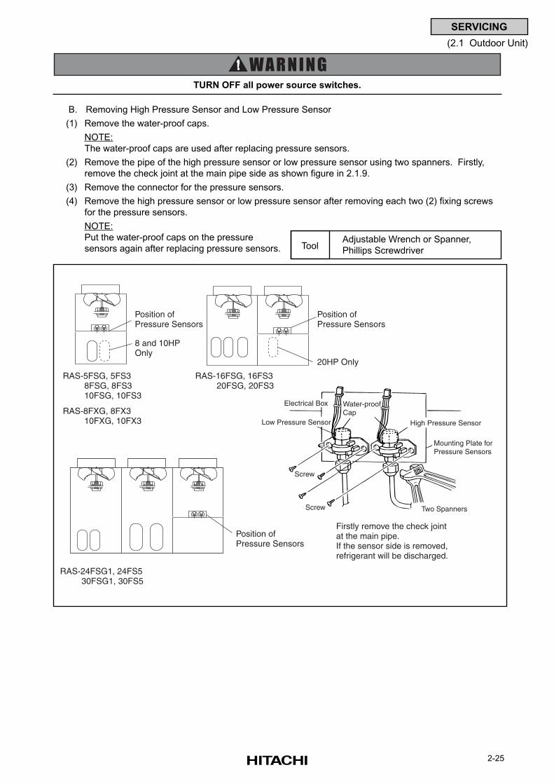
2-25
SERVICING
(2.1 Outdoor Unit)
B. Removing High Pressure Sensor and Low Pressure Sensor
(1) Remove the water-proof caps.
NOTE:
The water-proof caps are used after replacing pressure sensors.
(2) Remove the pipe of the high pressure sensor or low pressure sensor using two spanners. Firstly,
remove the check joint at the main pipe side as shown figure in 2.1.9.
(3) Remove the connector for the pressure sensors.
(4) Remove the high pressure sensor or low pressure sensor after removing each two (2) fixing screws
for the pressure sensors.
NOTE:
Put the water-proof caps on the pressure
sensors again after replacing pressure sensors.
TURN OFF all power source switches.
Adjustable Wrench or Spanner,
Phillips ScrewdriverTool
RAS-5FSG, 5FS3 8FSG, 8FS3 10FSG, 10FS3
RAS-8FXG, 8FX3 10FXG, 10FX3
RAS-16FSG, 16FS3 20FSG, 20FS3
RAS-24FSG1, 24FS5 30FSG1, 30FS5
Firstly remove the check jointat the main pipe.If the sensor side is removed,refrigerant will be discharged.
Screw
Screw
Two Spanners
Mounting Plate forPressure Sensors
High Pressure Sensor
Water-proofCap
Electrical Box
Low Pressure Sensor
Position of Pressure Sensors
Position of Pressure Sensors
Position of Pressure Sensors
8 and 10HPOnly
20HP Only
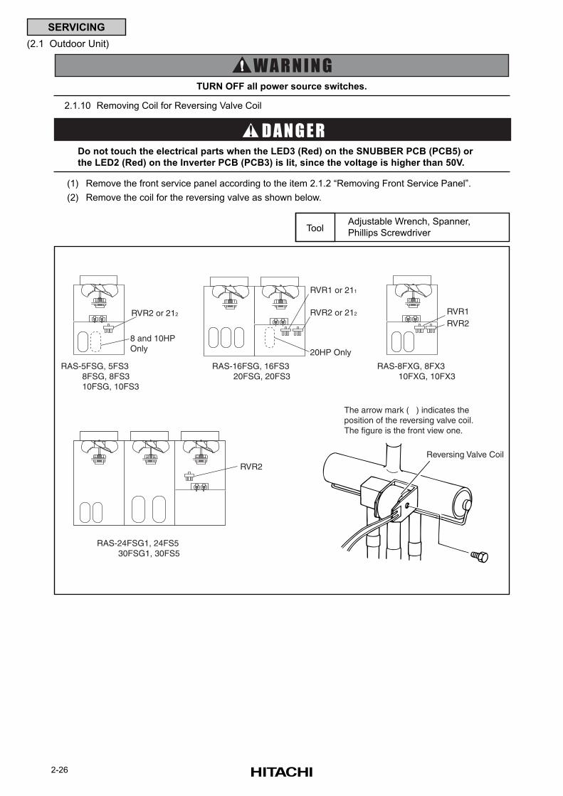
2-26
SERVICING
(2.1 Outdoor Unit)
(1) Remove the front service panel according to the item 2.1.2 “Removing Front Service Panel”.
(2) Remove the coil for the reversing valve as shown below.
2.1.10 Removing Coil for Reversing Valve Coil
TURN OFF all power source switches.
Do not touch the electrical parts when the LED3 (Red) on the SNUBBER PCB (PCB5) or
the LED2 (Red) on the Inverter PCB (PCB3) is lit, since the voltage is higher than 50V.
Adjustable Wrench, Spanner,
Phillips ScrewdriverTool
The arrow mark ( ) indicates theposition of the reversing valve coil.The figure is the front view one.
Reversing Valve Coil
RAS-24FSG1, 24FS5 30FSG1, 30FS5
RVR2
RAS-5FSG, 5FS3 8FSG, 8FS3 10FSG, 10FS3
RAS-8FXG, 8FX3 10FXG, 10FX3
RAS-16FSG, 16FS3 20FSG, 20FS3
8 and 10HPOnly 20HP Only
RVR2 or 212 RVR1RVR2
RVR1 or 211
RVR2 or 212
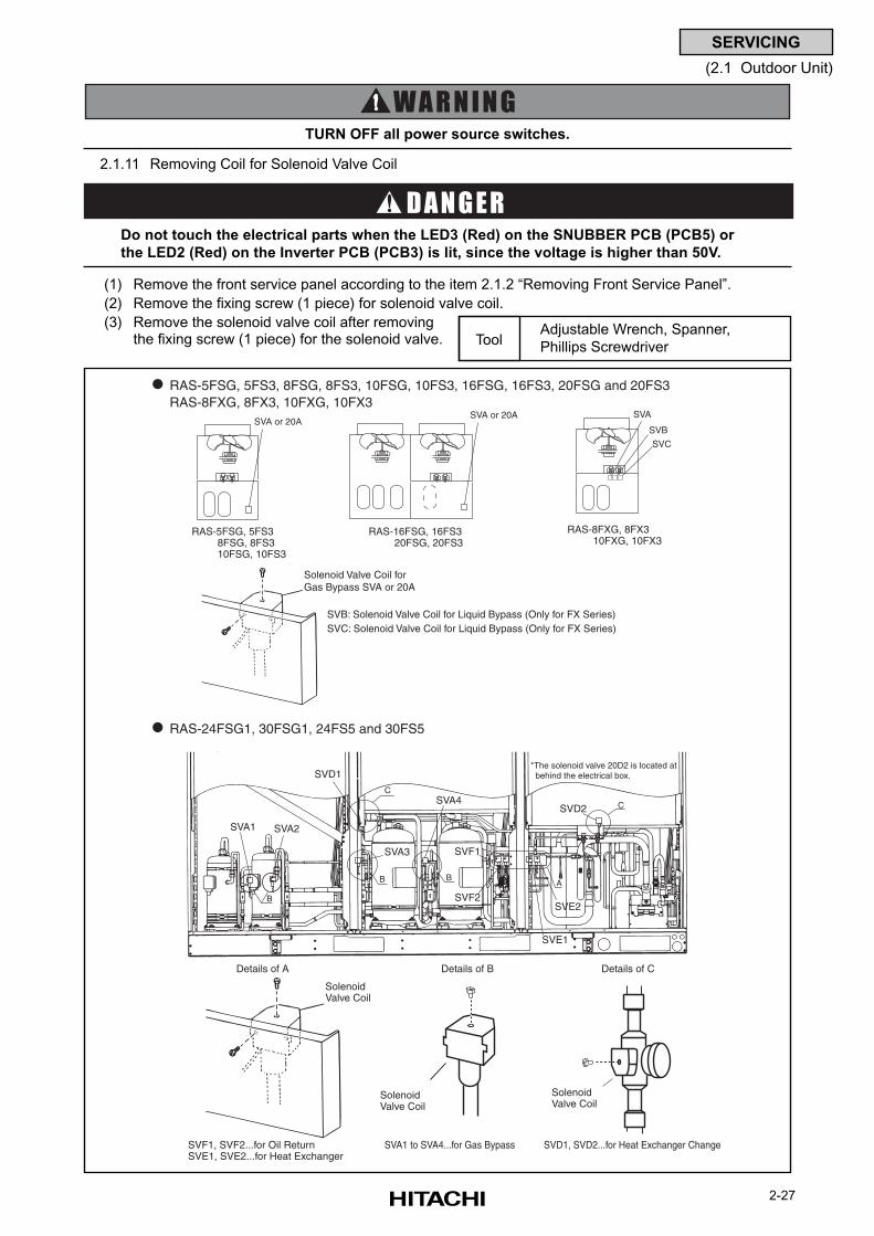
2-27
SERVICING
(2.1 Outdoor Unit)
(1) Remove the front service panel according to the item 2.1.2 “Removing Front Service Panel”.
(2) Remove the fixing screw (1 piece) for solenoid valve coil.
(3) Remove the solenoid valve coil after removingthe fixing screw (1 piece) for the solenoid valve.
2.1.11 Removing Coil for Solenoid Valve Coil
TURN OFF all power source switches.
Do not touch the electrical parts when the LED3 (Red) on the SNUBBER PCB (PCB5) or
the LED2 (Red) on the Inverter PCB (PCB3) is lit, since the voltage is higher than 50V.
Adjustable Wrench, Spanner,
Phillips ScrewdriverTool
Details of A Details of B Details of C
SolenoidValve Coil
Solenoid Valve Coil
Solenoid Valve Coil
SVF1, SVF2...for Oil ReturnSVE1, SVE2...for Heat Exchanger
SVA1 to SVA4...for Gas Bypass SVD1, SVD2...for Heat Exchanger Change
SVD1
SVA3
SVA4
SVF1
SVF2
SVE1
SVE2
SVD2
AB B
B
C
C
SVA1 SVA2
*The solenoid valve 20D2 is located at behind the electrical box.
RAS-24FSG1, 30FSG1, 24FS5 and 30FS5
Solenoid Valve Coil forGas Bypass SVA or 20A
RAS-5FSG, 5FS3, 8FSG, 8FS3, 10FSG, 10FS3, 16FSG, 16FS3, 20FSG and 20FS3RAS-8FXG, 8FX3, 10FXG, 10FX3
RAS-16FSG, 16FS3 20FSG, 20FS3
SVA or 20A
RAS-5FSG, 5FS3 8FSG, 8FS3 10FSG, 10FS3
SVA or 20A
RAS-8FXG, 8FX3 10FXG, 10FX3
SVA
SVB
SVC
SVB: Solenoid Valve Coil for Liquid Bypass (Only for FX Series)SVC: Solenoid Valve Coil for Liquid Bypass (Only for FX Series)
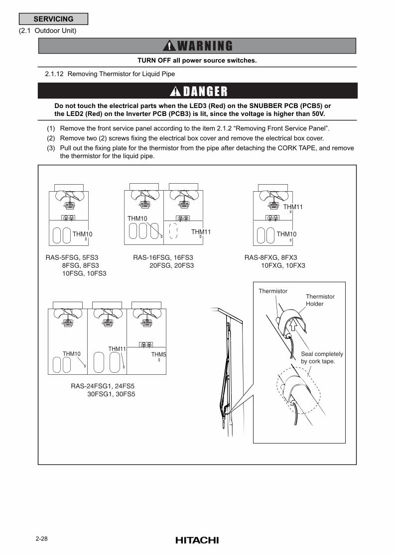
2-28
SERVICING
(2.1 Outdoor Unit)
(1) Remove the front service panel according to the item 2.1.2 “Removing Front Service Panel”.
(2) Remove two (2) screws fixing the electrical box cover and remove the electrical box cover.
(3) Pull out the fixing plate for the thermistor from the pipe after detaching the CORK TAPE, and remove
the thermistor for the liquid pipe.
2.1.12 Removing Thermistor for Liquid Pipe
TURN OFF all power source switches.
Do not touch the electrical parts when the LED3 (Red) on the SNUBBER PCB (PCB5) or
the LED2 (Red) on the Inverter PCB (PCB3) is lit, since the voltage is higher than 50V.
RAS-5FSG, 5FS3 8FSG, 8FS3 10FSG, 10FS3
RAS-8FXG, 8FX3 10FXG, 10FX3
RAS-16FSG, 16FS3 20FSG, 20FS3
THM10
THM11
ThermistorThermistorHolder
Seal completelyby cork tape.
THM10 THM10
RAS-24FSG1, 24FS5 30FSG1, 30FS5
THM11
THM11THM5THM10
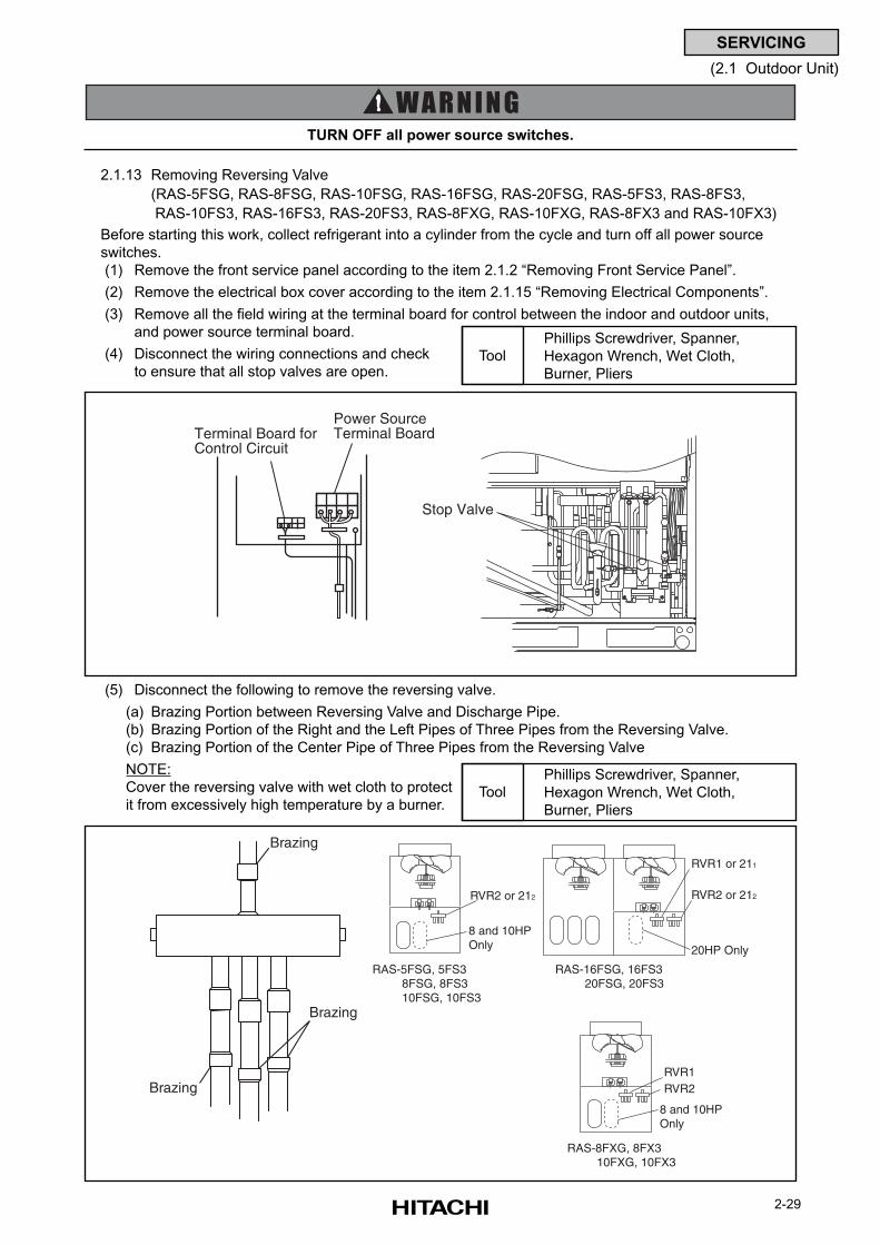
2-29
SERVICING
(2.1 Outdoor Unit)
2.1.13 Removing Reversing Valve
(RAS-5FSG, RAS-8FSG, RAS-10FSG, RAS-16FSG, RAS-20FSG, RAS-5FS3, RAS-8FS3,
RAS-10FS3, RAS-16FS3, RAS-20FS3, RAS-8FXG, RAS-10FXG, RAS-8FX3 and RAS-10FX3)
Before starting this work, collect refrigerant into a cylinder from the cycle and turn off all power source
switches.
(1) Remove the front service panel according to the item 2.1.2 “Removing Front Service Panel”.
(2) Remove the electrical box cover according to the item 2.1.15 “Removing Electrical Components”.
(3) Remove all the field wiring at the terminal board for control between the indoor and outdoor units,
and power source terminal board.
(4) Disconnect the wiring connections and check
to ensure that all stop valves are open.
TURN OFF all power source switches.
(5) Disconnect the following to remove the reversing valve.
(a) Brazing Portion between Reversing Valve and Discharge Pipe.
(b) Brazing Portion of the Right and the Left Pipes of Three Pipes from the Reversing Valve.
(c) Brazing Portion of the Center Pipe of Three Pipes from the Reversing Valve
NOTE:
Cover the reversing valve with wet cloth to protect
it from excessively high temperature by a burner.
Phillips Screwdriver, Spanner,
Hexagon Wrench, Wet Cloth,
Burner, Pliers
Tool
Phillips Screwdriver, Spanner,
Hexagon Wrench, Wet Cloth,
Burner, Pliers
Tool
RAS-5FSG, 5FS3 8FSG, 8FS3 10FSG, 10FS3
RAS-8FXG, 8FX3 10FXG, 10FX3
RAS-16FSG, 16FS3 20FSG, 20FS3
8 and 10HPOnly 20HP Only
RVR2 or 212
8 and 10HPOnly
RVR1RVR2
RVR1 or 211
RVR2 or 212
Brazing
Brazing
Brazing
Stop Valve
Power Source Terminal BoardTerminal Board for
Control Circuit
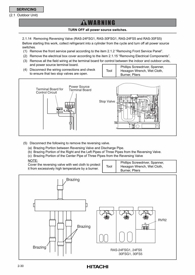
2-30
SERVICING
(2.1 Outdoor Unit)
2.1.14 Removing Reversing Valve (RAS-24FSG1, RAS-30FSG1, RAS-24FS5 and RAS-30FS5)
Before starting this work, collect refrigerant into a cylinder from the cycle and turn off all power source
switches.
(1) Remove the front service panel according to the item 2.1.2 “Removing Front Service Panel”.
(2) Remove the electrical box cover according to the item 2.1.15 “Removing Electrical Components”.
(3) Remove all the field wiring at the terminal board for control between the indoor and outdoor units,
and power source terminal board.
(4) Disconnect the wiring connections and check
to ensure that two stop valves are open.
TURN OFF all power source switches.
(5) Disconnect the following to remove the reversing valve.
(a) Brazing Portion between Reversing Valve and Discharge Pipe.
(b) Brazing Portion of the Right and the Left Pipes of Three Pipes from the Reversing Valve.
(c) Brazing Portion of the Center Pipe of Three Pipes from the Reversing Valve
NOTE:
Cover the reversing valve with wet cloth to protect
it from excessively high temperature by a burner.
Phillips Screwdriver, Spanner,
Hexagon Wrench, Wet Cloth,
Burner, Pliers
Tool
Phillips Screwdriver, Spanner,
Hexagon Wrench, Wet Cloth,
Burner, Pliers
Tool
Power Source Terminal BoardTerminal Board for
Control Circuit
Stop Valve
R40
7R
407
R407
R407
Brazing
Brazing
BrazingRAS-24FSG1, 24FS5 30FSG1, 30FS5
RVR2
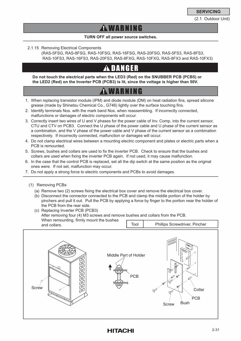
2-31
SERVICING
(2.1 Outdoor Unit)
(1) Removing PCBs
(a) Remove two (2) screws fixing the electrical box cover and remove the electrical box cover.
(b) Disconnect the connector connected to the PCB and clamp the middle portion of the holder by
pinchers and pull it out. Pull the PCB by applying a force by finger to the portion near the holder of
the PCB from the rear side.
(c) Replacing Inverter PCB (PCB3)
After removing four (4) M3 screws and remove bushes and collars from the PCB.
When remounting, firmly mount the bushes
and collars.
TURN OFF all power source switches.
1. When replacing transistor module (IPM) and diode module (DM) on heat radiation fins, spread silicone
grease (made by Shinetsu Chemical Co., G746) lightly over the surface touching fins.
2. Identify terminals Nos. with the mark band Nos. when reassembling. If incorrectly connected,
malfunctions or damages of electric components will occur.
3. Correctly insert two wires of U and V phases for the power cable of Inv. Comp. into the current sensor,
CTU and CTV on PCB3. Connect the U phase of the power cable and U phase of the current sensor as
a combination, and the V phase of the power cable and V phase of the current sensor as a combination
respectively. If incorrectly connected, malfunction or damages will occur.
4. Do not clamp electrical wires between a mounting electric component and plates or electric parts when a
PCB is remounted.
5. Screws, bushes and collars are used to fix the inverter PCB. Check to ensure that the bushes and
collars are used when fixing the inverter PCB again. If not used, it may cause malfunction.
6. In the case that the control PCB is replaced, set all the dip switch at the same position as the original
ones were. If not set, malfunction may occur.
7. Do not apply a strong force to electric components and PCBs to avoid damages.
2.1.15 Removing Electrical Components
(RAS-5FSG, RAS-8FSG, RAS-10FSG, RAS-16FSG, RAS-20FSG, RAS-5FS3, RAS-8FS3,
RAS-10FS3, RAS-16FS3, RAS-20FS3, RAS-8FXG, RAS-10FXG, RAS-8FX3 and RAS-10FX3)
Do not touch the electrical parts when the LED3 (Red) on the SNUBBER PCB (PCB5) or
the LED2 (Red) on the Inverter PCB (PCB3) is lit, since the voltage is higher than 50V.
Phillips Screwdriver, PincherTool
Screw
PCB
Screw BushPCB
Collar
Middle Part of Holder
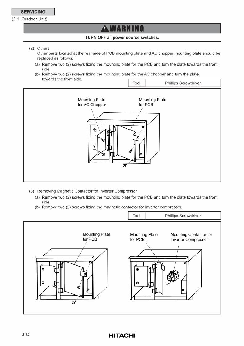
2-32
SERVICING
(2.1 Outdoor Unit)
TURN OFF all power source switches.
(2) Others
Other parts located at the rear side of PCB mounting plate and AC chopper mounting plate should be
replaced as follows.
(a) Remove two (2) screws fixing the mounting plate for the PCB and turn the plate towards the front
side.
(b) Remove two (2) screws fixing the mounting plate for the AC chopper and turn the plate
towards the front side.Phillips ScrewdriverTool
(3) Removing Magnetic Contactor for Inverter Compressor
(a) Remove two (2) screws fixing the mounting plate for the PCB and turn the plate towards the front
side.
(b) Remove two (2) screws fixing the magnetic contactor for inverter compressor.
Phillips ScrewdriverTool
Mounting Platefor AC Chopper
Mounting Platefor PCB
Mounting Platefor PCB
Mounting Platefor PCB
Mounting Contactor forInverter Compressor
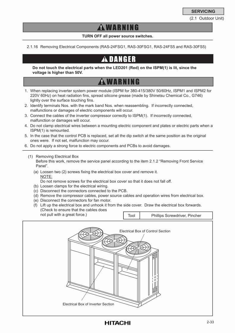
2-33
SERVICING
(2.1 Outdoor Unit)
(1) Removing Electrical Box
Before this work, remove the service panel according to the item 2.1.2 “Removing Front Service
Panel”.
(a) Loosen two (2) screws fixing the electrical box cover and remove it.
NOTE:
Do not remove screws for the electrical box cover so that it does not fall off.
(b) Loosen clamps for the electrical wiring.
(c) Disconnect the connectors connected to the PCB.
(d) Remove the compressor cables, power source cables and operation wires from electrical box.
(e) Disconnect the connectors for fan motor.
(f) Lift up the electrical box and unhook it from the side cover. Draw the electrical box forwards.
(Check to ensure that the cables does
not pull with a great force.)
TURN OFF all power source switches.
1. When replacing inverter system power module (ISPM for 380-415/380V 50/60Hz, ISPM1 and ISPM2 for
220V 60Hz) on heat radiation fins, spread silicone grease (made by Shinetsu Chemical Co., G746)
lightly over the surface touching fins.
2. Identify terminals Nos. with the mark band Nos. when reassembling. If incorrectly connected,
malfunctions or damages of electric components will occur.
3. Connect the cables of the inverter compressor correctly to ISPM(1). If incorrectly connected,
malfunction or damages will occur.
4. Do not clamp electrical wires between a mounting electric component and plates or electric parts when a
ISPM(1) is remounted.
5. In the case that the control PCB is replaced, set all the dip switch at the same position as the original
ones were. If not set, malfunction may occur.
6. Do not apply a strong force to electric components and PCBs to avoid damages.
2.1.16 Removing Electrical Components (RAS-24FSG1, RAS-30FSG1, RAS-24FS5 and RAS-30FS5)
Do not touch the electrical parts when the LED201 (Red) on the ISPM(1) is lit, since the
voltage is higher than 50V.
Phillips Screwdriver, PincherTool
Electrical Box of Inverter Section
Electrical Box of Control Section
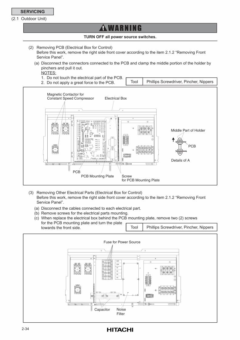
2-34
SERVICING
(2.1 Outdoor Unit)
TURN OFF all power source switches.
(2) Removing PCB (Electrical Box for Control)
Before this work, remove the right side front cover according to the item 2.1.2 “Removing Front
Service Panel”.
(a) Disconnect the connectors connected to the PCB and clamp the middle portion of the holder by
pinchers and pull it out.
NOTES:
1. Do not touch the electrical part of the PCB.
2. Do not apply a great force to the PCB. Phillips Screwdriver, Pincher, NippersTool
(3) Removing Other Electrical Parts (Electrical Box for Control)
Before this work, remove the right side front cover according to the item 2.1.2 “Removing Front
Service Panel”.
(a) Disconnect the cables connected to each electrical part.
(b) Remove screws for the electrical parts mounting.
(c) When replace the electrical box behind the PCB mounting plate, remove two (2) screws
for the PCB mounting plate and turn the plate
towards the front side. Phillips Screwdriver, Pincher, NippersTool
TL3L1 L2
R S MPN
S TR
L1L2
L3N
M63826P
M63826P
IC9IC2
C12
+
C10
++
DSW6 DSW7 DSW8 DSW9
DSW4 DSW5
1 2 4321 1 2 3 41 2
521 4 63 7631 2 54 8
PC1 PC2
D122
R144
DSW1 DSW2 DSW3 PSW1 PSW2 PSW33 41 2 3 41 2 1 2
Magnetic Contactor forConstant Speed Compressor Electrical Box
Screwfor PCB Mounting Plate
PCB Mounting Plate
PCB
Middle Part of Holder
A
Details of A
PCB
S TR
TL3L1 L2
R S MPN
L1L2
L3N
32A
32A
(a)
(a)
(a)
(a)
Fuse for Power Source
NoiseFilter
Capacitor
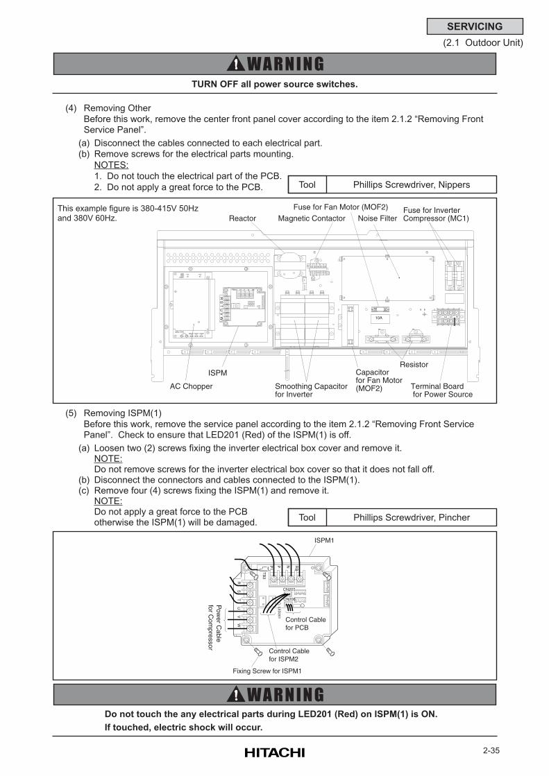
2-35
SERVICING
(2.1 Outdoor Unit)
TURN OFF all power source switches.
(5) Removing ISPM(1)
Before this work, remove the service panel according to the item 2.1.2 “Removing Front ServicePanel”. Check to ensure that LED201 (Red) of the ISPM(1) is off.
(a) Loosen two (2) screws fixing the inverter electrical box cover and remove it.NOTE:Do not remove screws for the inverter electrical box cover so that it does not fall off.
(b) Disconnect the connectors and cables connected to the ISPM(1).(c) Remove four (4) screws fixing the ISPM(1) and remove it.
NOTE:Do not apply a great force to the PCBotherwise the ISPM(1) will be damaged.
(4) Removing Other
Before this work, remove the center front panel cover according to the item 2.1.2 “Removing FrontService Panel”.
(a) Disconnect the cables connected to each electrical part.
(b) Remove screws for the electrical parts mounting.
NOTES:
1. Do not touch the electrical part of the PCB.
2. Do not apply a great force to the PCB.
Phillips Screwdriver, PincherTool
Do not touch the any electrical parts during LED201 (Red) on ISPM(1) is ON.
If touched, electric shock will occur.
TB
3
P1
CN206
LED
201
CN207
ISPM1
Fixing Screw for ISPM1
Control Cablefor ISPM2
Control Cablefor PCB
Pow
er Cable
for Com
pressor
RS
TU
VW
P N RB
10A
WV
RS
UT
RBNPP1
C
PD
R1CN201 S1
COM1SUB1MAIN1COM2
L1 L2 L3 N
AC Chopper
ISPM
Smoothing Capacitorfor Inverter
Reactor Magnetic Contactor
Capacitor for Fan Motor(MOF2)
Resistor
Terminal Board for Power Source
Noise FilterFuse for Inverter Compressor (MC1)
Fuse for Fan Motor (MOF2)
Phillips Screwdriver, NippersTool
This example figure is 380-415V 50Hzand 380V 60Hz.
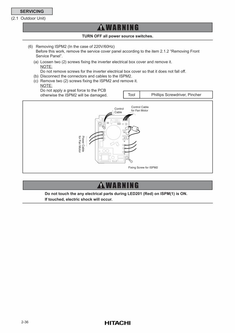
2-36
SERVICING
(2.1 Outdoor Unit)
TURN OFF all power source switches.
(6) Removing ISPM2 (In the case of 220V/60Hz)
Before this work, remove the service cover panel according to the item 2.1.2 “Removing Front
Service Panel”.
(a) Loosen two (2) screws fixing the inverter electrical box cover and remove it.
NOTE:
Do not remove screws for the inverter electrical box cover so that it does not fall off.
(b) Disconnect the connectors and cables to the ISPM2.
(c) Remove two (2) screws fixing the ISPM2 and remove it.
NOTE:
Do not apply a great force to the PCB
otherwise the ISPM2 will be damaged. Phillips Screwdriver, PincherTool
Fixing Screw for ISPM2
Control Cablefor Fan Motor
Control Cable
Pow
er Cable
for Fan Motor
U
V
W
R
S
T
N
P
PD
Do not touch the any electrical parts during LED201 (Red) on ISPM(1) is ON.
If touched, electric shock will occur.
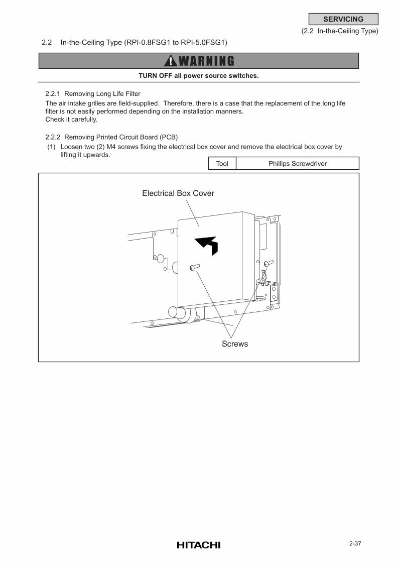
2-37
SERVICING
(2.2 In-the-Ceiling Type)
2.2 In-the-Ceiling Type (RPI-0.8FSG1 to RPI-5.0FSG1)
2.2.1 Removing Long Life Filter
The air intake grilles are field-supplied. Therefore, there is a case that the replacement of the long life
filter is not easily performed depending on the installation manners.
Check it carefully.
2.2.2 Removing Printed Circuit Board (PCB)
(1) Loosen two (2) M4 screws fixing the electrical box cover and remove the electrical box cover by
lifting it upwards.
Phillips ScrewdriverTool
TURN OFF all power source switches.
Electrical Box Cover
Screws
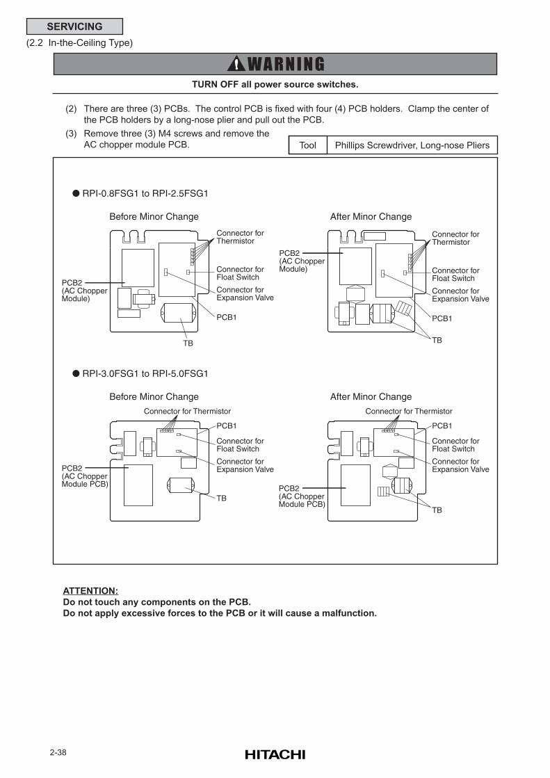
2-38
SERVICING
(2.2 In-the-Ceiling Type)
(2) There are three (3) PCBs. The control PCB is fixed with four (4) PCB holders. Clamp the center of
the PCB holders by a long-nose plier and pull out the PCB.
(3) Remove three (3) M4 screws and remove the
AC chopper module PCB. Phillips Screwdriver, Long-nose PliersTool
TURN OFF all power source switches.
ATTENTION:
Do not touch any components on the PCB.
Do not apply excessive forces to the PCB or it will cause a malfunction.
Before Minor Change After Minor Change
RPI-0.8FSG1 to RPI-2.5FSG1
Connector forThermistor
Connector forFloat Switch
Connector forExpansion Valve
PCB1
TB
PCB2(AC ChopperModule)
PCB2(AC ChopperModule)
Connector forThermistor
Connector forFloat Switch
Connector forExpansion Valve
PCB1
RPI-3.0FSG1 to RPI-5.0FSG1
Before Minor Change
PCB2(AC ChopperModule PCB)
Connector forFloat Switch
Connector forExpansion Valve
PCB1
Connector for Thermistor Connector for Thermistor
Connector forFloat Switch
Connector forExpansion Valve
PCB1
PCB2(AC ChopperModule PCB)
TB
TB
TB
After Minor Change
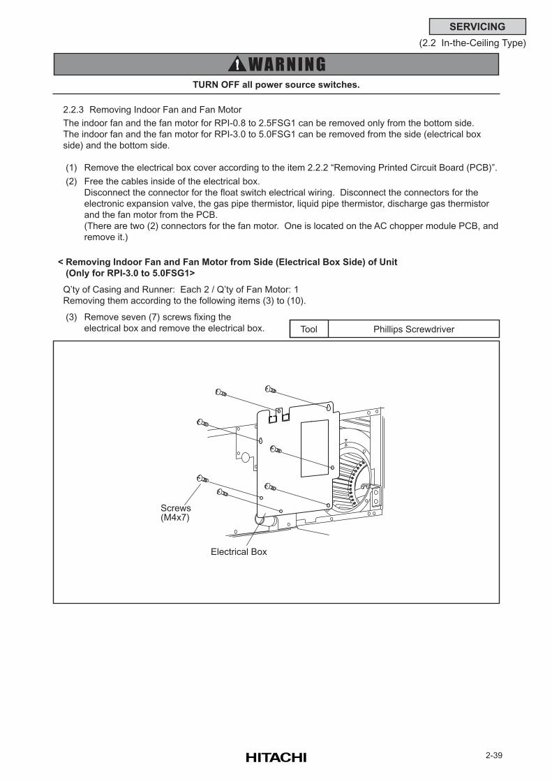
2-39
SERVICING
(2.2 In-the-Ceiling Type)
2.2.3 Removing Indoor Fan and Fan Motor
The indoor fan and the fan motor for RPI-0.8 to 2.5FSG1 can be removed only from the bottom side.
The indoor fan and the fan motor for RPI-3.0 to 5.0FSG1 can be removed from the side (electrical box
side) and the bottom side.
(1) Remove the electrical box cover according to the item 2.2.2 “Removing Printed Circuit Board (PCB)”.
(2) Free the cables inside of the electrical box.
Disconnect the connector for the float switch electrical wiring. Disconnect the connectors for the
electronic expansion valve, the gas pipe thermistor, liquid pipe thermistor, discharge gas thermistor
and the fan motor from the PCB.
(There are two (2) connectors for the fan motor. One is located on the AC chopper module PCB, and
remove it.)
< Removing Indoor Fan and Fan Motor from Side (Electrical Box Side) of Unit
(Only for RPI-3.0 to 5.0FSG1>
Q’ty of Casing and Runner: Each 2 / Q’ty of Fan Motor: 1
Removing them according to the following items (3) to (10).
(3) Remove seven (7) screws fixing the
electrical box and remove the electrical box. Phillips ScrewdriverTool
TURN OFF all power source switches.
Screws(M4x7)
Electrical Box
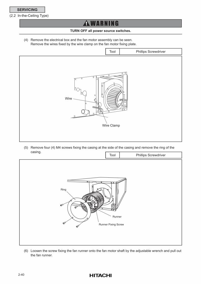
2-40
SERVICING
(2.2 In-the-Ceiling Type)
(4) Remove the electrical box and the fan motor assembly can be seen.
Remove the wires fixed by the wire clamp on the fan motor fixing plate.
Phillips ScrewdriverTool
TURN OFF all power source switches.
(5) Remove four (4) M4 screws fixing the casing at the side of the casing and remove the ring of the
casing.Phillips ScrewdriverTool
(6) Loosen the screw fixing the fan runner onto the fan motor shaft by the adjustable wrench and pull out
the fan runner.
Ring
Runner Fixing Screw
Runner
Wire Clamp
Wire
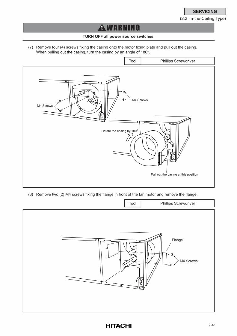
2-41
SERVICING
(2.2 In-the-Ceiling Type)
(7) Remove four (4) screws fixing the casing onto the motor fixing plate and pull out the casing.
When pulling out the casing, turn the casing by an angle of 180°.
Phillips ScrewdriverTool
(8) Remove two (2) M4 screws fixing the flange in front of the fan motor and remove the flange.
Phillips ScrewdriverTool
TURN OFF all power source switches.
Flange
M4 Screws
Rotate the casing by 180o
Pull out the casing at this position
M4 Screws
M4 Screws
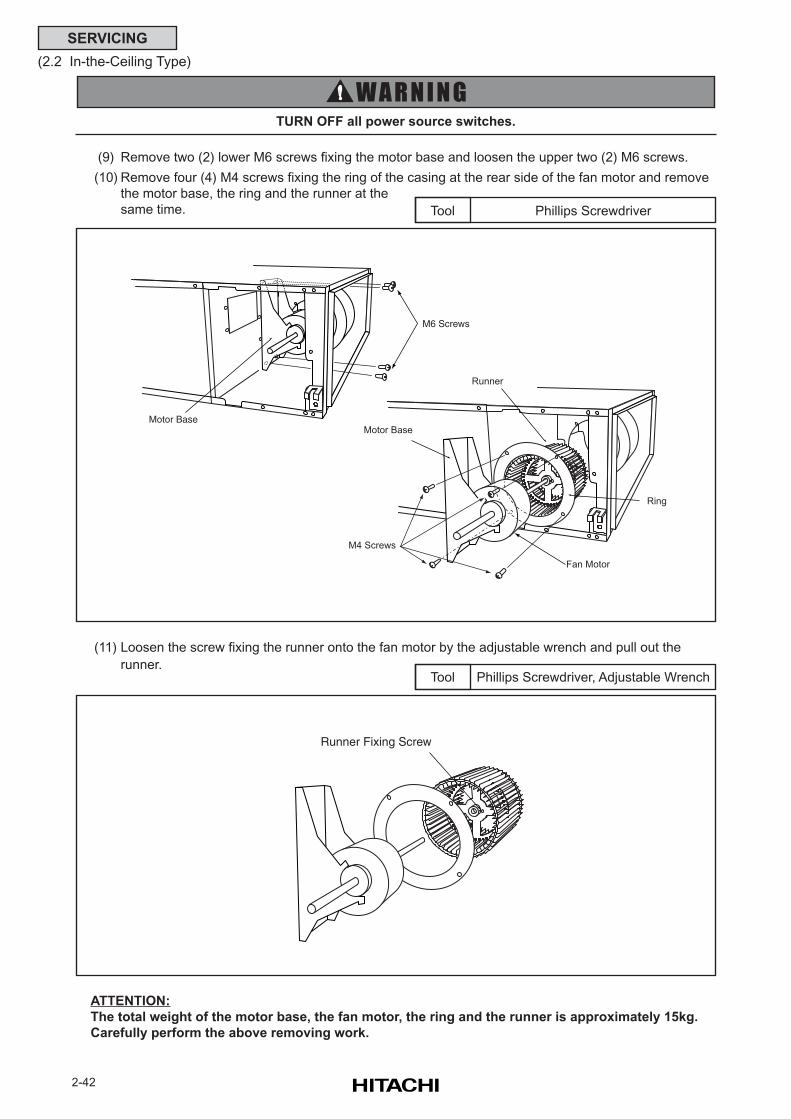
2-42
SERVICING
(2.2 In-the-Ceiling Type)
(9) Remove two (2) lower M6 screws fixing the motor base and loosen the upper two (2) M6 screws.
(10) Remove four (4) M4 screws fixing the ring of the casing at the rear side of the fan motor and remove
the motor base, the ring and the runner at the
same time. Phillips ScrewdriverTool
TURN OFF all power source switches.
(11) Loosen the screw fixing the runner onto the fan motor by the adjustable wrench and pull out the
runner.Phillips Screwdriver, Adjustable WrenchTool
ATTENTION:
The total weight of the motor base, the fan motor, the ring and the runner is approximately 15kg.
Carefully perform the above removing work.
Runner Fixing Screw
M6 Screws
Motor Base
Ring
M4 Screws
Motor Base
Fan Motor
Runner
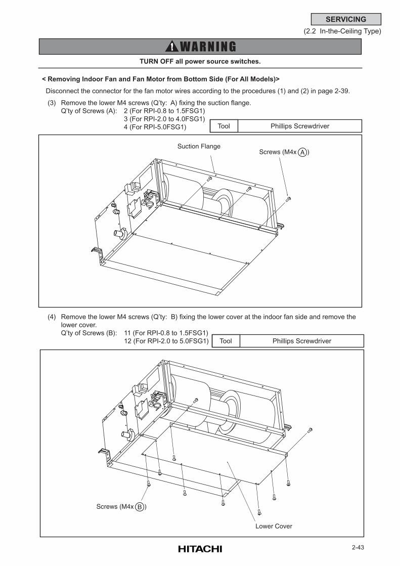
2-43
SERVICING
(2.2 In-the-Ceiling Type)
< Removing Indoor Fan and Fan Motor from Bottom Side (For All Models)>
Disconnect the connector for the fan motor wires according to the procedures (1) and (2) in page 2-39.
(3) Remove the lower M4 screws (Q’ty: A) fixing the suction flange.
Q’ty of Screws (A): 2 (For RPI-0.8 to 1.5FSG1)
3 (For RPI-2.0 to 4.0FSG1)
4 (For RPI-5.0FSG1) Phillips ScrewdriverTool
(4) Remove the lower M4 screws (Q’ty: B) fixing the lower cover at the indoor fan side and remove the
lower cover.
Q’ty of Screws (B): 11 (For RPI-0.8 to 1.5FSG1)
12 (For RPI-2.0 to 5.0FSG1) Phillips ScrewdriverTool
TURN OFF all power source switches.
Screws (M4x )ASuction Flange
Screws (M4x )B
Lower Cover
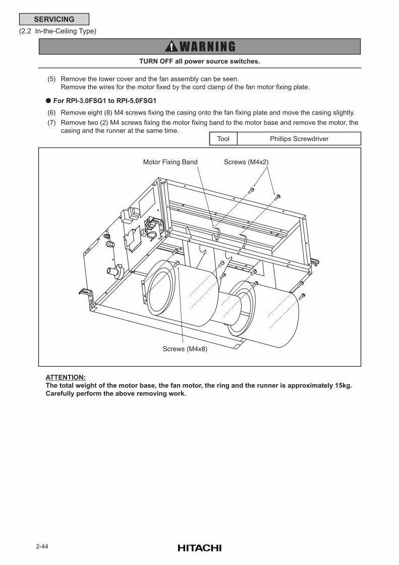
2-44
SERVICING
(2.2 In-the-Ceiling Type)
(5) Remove the lower cover and the fan assembly can be seen.
Remove the wires for the motor fixed by the cord clamp of the fan motor fixing plate.
For RPI-3.0FSG1 to RPI-5.0FSG1
(6) Remove eight (8) M4 screws fixing the casing onto the fan fixing plate and move the casing slightly.
(7) Remove two (2) M4 screws fixing the motor fixing band to the motor base and remove the motor, the
casing and the runner at the same time.
Phillips ScrewdriverTool
ATTENTION:
The total weight of the motor base, the fan motor, the ring and the runner is approximately 15kg.
Carefully perform the above removing work.
TURN OFF all power source switches.
Motor Fixing Band Screws (M4x2)
Screws (M4x8)
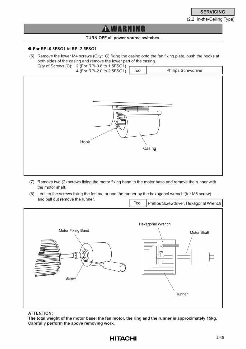
2-45
SERVICING
(2.2 In-the-Ceiling Type)
ATTENTION:
The total weight of the motor base, the fan motor, the ring and the runner is approximately 15kg.
Carefully perform the above removing work.
For RPI-0.8FSG1 to RPI-2.5FSG1
(6) Remove the lower M4 screws (Q’ty: C) fixing the casing onto the fan fixing plate, push the hooks at
both sides of the casing and remove the lower part of the casing.
Q’ty of Screws (C): 2 (For RPI-0.8 to 1.5FSG1)
4 (For RPI-2.0 to 2.5FSG1) Phillips ScrewdriverTool
(7) Remove two (2) screws fixing the motor fixing band to the motor base and remove the runner with
the motor shaft.
(8) Loosen the screws fixing the fan motor and the runner by the hexagonal wrench (for M6 screw)
and pull out remove the runner.Phillips Screwdriver, Hexagonal WrenchTool
TURN OFF all power source switches.
Hook
Casing
Motor Fixing Band
Screw
Runner
Hexagonal Wrench
Motor Shaft
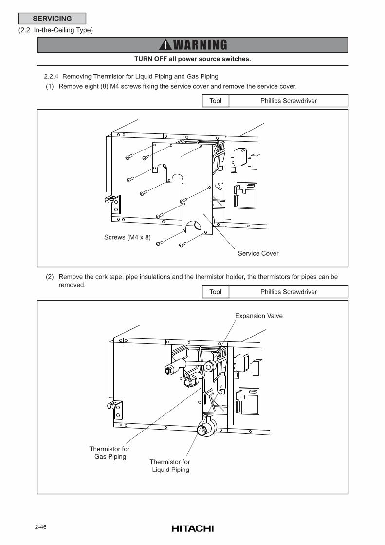
2-46
SERVICING
(2.2 In-the-Ceiling Type)
2.2.4 Removing Thermistor for Liquid Piping and Gas Piping
(1) Remove eight (8) M4 screws fixing the service cover and remove the service cover.
Phillips ScrewdriverTool
TURN OFF all power source switches.
(2) Remove the cork tape, pipe insulations and the thermistor holder, the thermistors for pipes can be
removed.Phillips ScrewdriverTool
Screws (M4 x 8)
Service Cover
Expansion Valve
Thermistor for Liquid Piping
Thermistor for Gas Piping
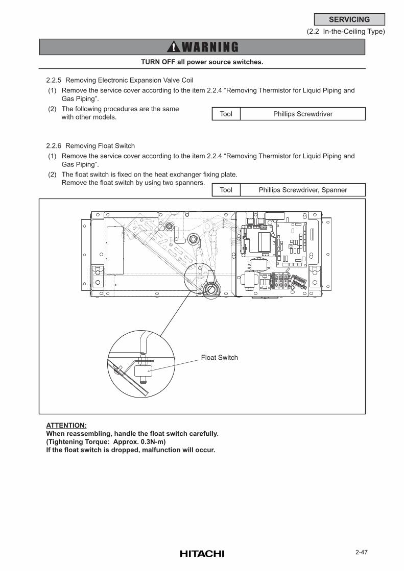
2-47
SERVICING
(2.2 In-the-Ceiling Type)
2.2.5 Removing Electronic Expansion Valve Coil
(1) Remove the service cover according to the item 2.2.4 “Removing Thermistor for Liquid Piping and
Gas Piping”.
(2) The following procedures are the same
with other models. Phillips ScrewdriverTool
Phillips Screwdriver, SpannerTool
2.2.6 Removing Float Switch
(1) Remove the service cover according to the item 2.2.4 “Removing Thermistor for Liquid Piping and
Gas Piping”.
(2) The float switch is fixed on the heat exchanger fixing plate.
Remove the float switch by using two spanners.
ATTENTION:
When reassembling, handle the float switch carefully.
(Tightening Torque: Approx. 0.3N-m)
If the float switch is dropped, malfunction will occur.
TURN OFF all power source switches.
Float Switch
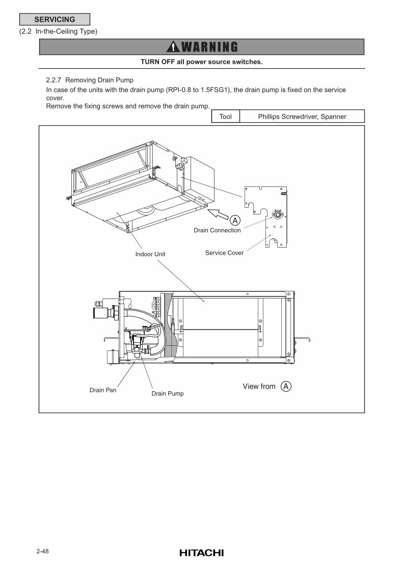
2-48
SERVICING
(2.2 In-the-Ceiling Type)
Phillips Screwdriver, SpannerTool
2.2.7 Removing Drain Pump
In case of the units with the drain pump (RPI-0.8 to 1.5FSG1), the drain pump is fixed on the service
cover.
Remove the fixing screws and remove the drain pump.
TURN OFF all power source switches.
Indoor Unit
Drain Connection
Service Cover
A
AView from Drain Pan Drain Pump
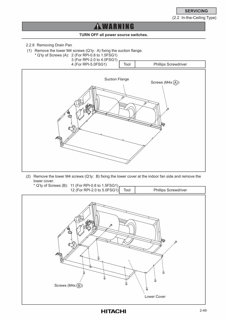
2-49
SERVICING
(2.2 In-the-Ceiling Type)
2.2.8 Removing Drain Pan
(1) Remove the lower M4 screws (Q’ty: A) fixing the suction flange.
* Q’ty of Screws (A): 2 (For RPI-0.8 to 1.5FSG1)
3 (For RPI-2.0 to 4.0FSG1)
4 (For RPI-5.0FSG1) Phillips ScrewdriverTool
(2) Remove the lower M4 screws (Q’ty: B) fixing the lower cover at the indoor fan side and remove the
lower cover.
* Q’ty of Screws (B): 11 (For RPI-0.8 to 1.5FSG1)
12 (For RPI-2.0 to 5.0FSG1) Phillips ScrewdriverTool
TURN OFF all power source switches.
Screws (M4x )ASuction Flange
Screws (M4x )B
Lower Cover
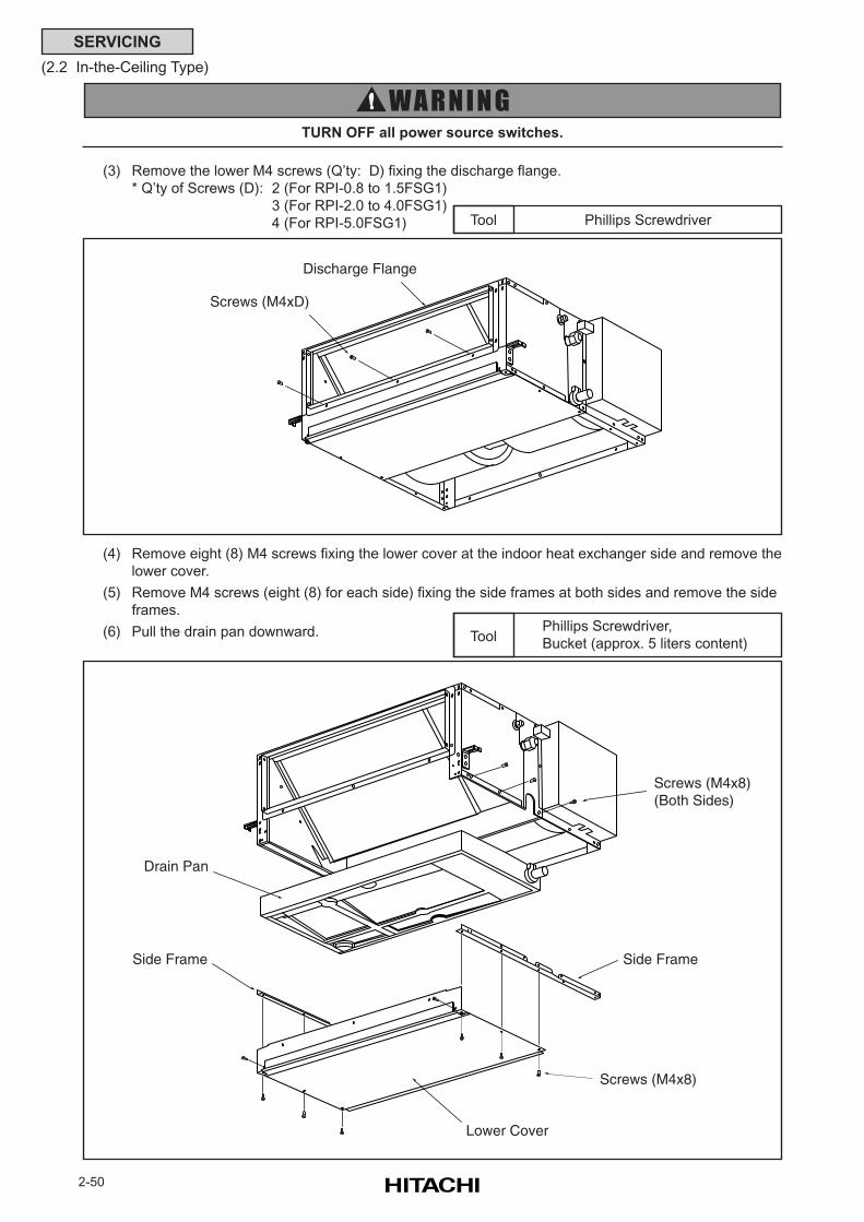
2-50
SERVICING
(2.2 In-the-Ceiling Type)
(3) Remove the lower M4 screws (Q’ty: D) fixing the discharge flange.
* Q’ty of Screws (D): 2 (For RPI-0.8 to 1.5FSG1)
3 (For RPI-2.0 to 4.0FSG1)
4 (For RPI-5.0FSG1) Phillips ScrewdriverTool
TURN OFF all power source switches.
(4) Remove eight (8) M4 screws fixing the lower cover at the indoor heat exchanger side and remove the
lower cover.
(5) Remove M4 screws (eight (8) for each side) fixing the side frames at both sides and remove the side
frames.
(6) Pull the drain pan downward. Phillips Screwdriver,
Bucket (approx. 5 liters content)Tool
Discharge Flange
Screws (M4xD)
Screws (M4x8) (Both Sides)
Side Frame
Drain Pan
Side Frame
Lower Cover
Screws (M4x8)
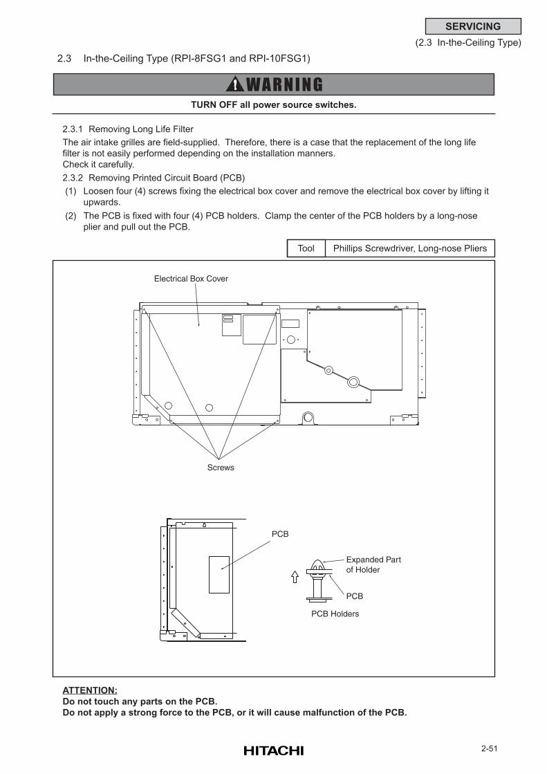
2-51
SERVICING
(2.3 In-the-Ceiling Type)
2.3 In-the-Ceiling Type (RPI-8FSG1 and RPI-10FSG1)
2.3.1 Removing Long Life Filter
The air intake grilles are field-supplied. Therefore, there is a case that the replacement of the long life
filter is not easily performed depending on the installation manners.
Check it carefully.
2.3.2 Removing Printed Circuit Board (PCB)
(1) Loosen four (4) screws fixing the electrical box cover and remove the electrical box cover by lifting it
upwards.
(2) The PCB is fixed with four (4) PCB holders. Clamp the center of the PCB holders by a long-nose
plier and pull out the PCB.
Phillips Screwdriver, Long-nose PliersTool
ATTENTION:
Do not touch any parts on the PCB.
Do not apply a strong force to the PCB, or it will cause malfunction of the PCB.
TURN OFF all power source switches.
Electrical Box Cover
Screws
Expanded Part of Holder
PCB
PCB Holders
PCB
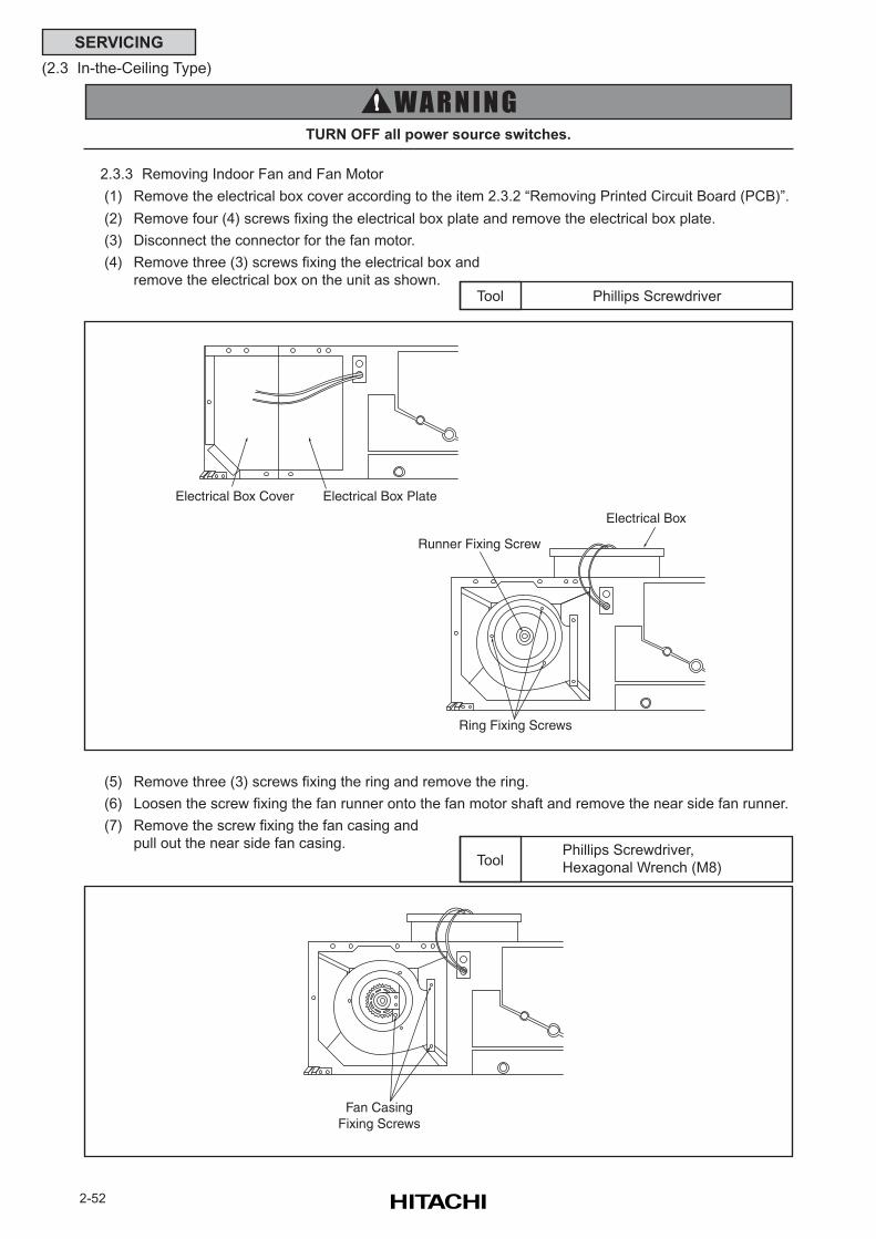
2-52
SERVICING
(2.3 In-the-Ceiling Type)
2.3.3 Removing Indoor Fan and Fan Motor
(1) Remove the electrical box cover according to the item 2.3.2 “Removing Printed Circuit Board (PCB)”.
(2) Remove four (4) screws fixing the electrical box plate and remove the electrical box plate.
(3) Disconnect the connector for the fan motor.
(4) Remove three (3) screws fixing the electrical box and
remove the electrical box on the unit as shown.Phillips ScrewdriverTool
TURN OFF all power source switches.
(5) Remove three (3) screws fixing the ring and remove the ring.
(6) Loosen the screw fixing the fan runner onto the fan motor shaft and remove the near side fan runner.
(7) Remove the screw fixing the fan casing and
pull out the near side fan casing. Phillips Screwdriver,
Hexagonal Wrench (M8)Tool
Electrical Box Cover Electrical Box Plate
Fan CasingFixing Screws
Ring Fixing Screws
Runner Fixing Screw
Electrical Box
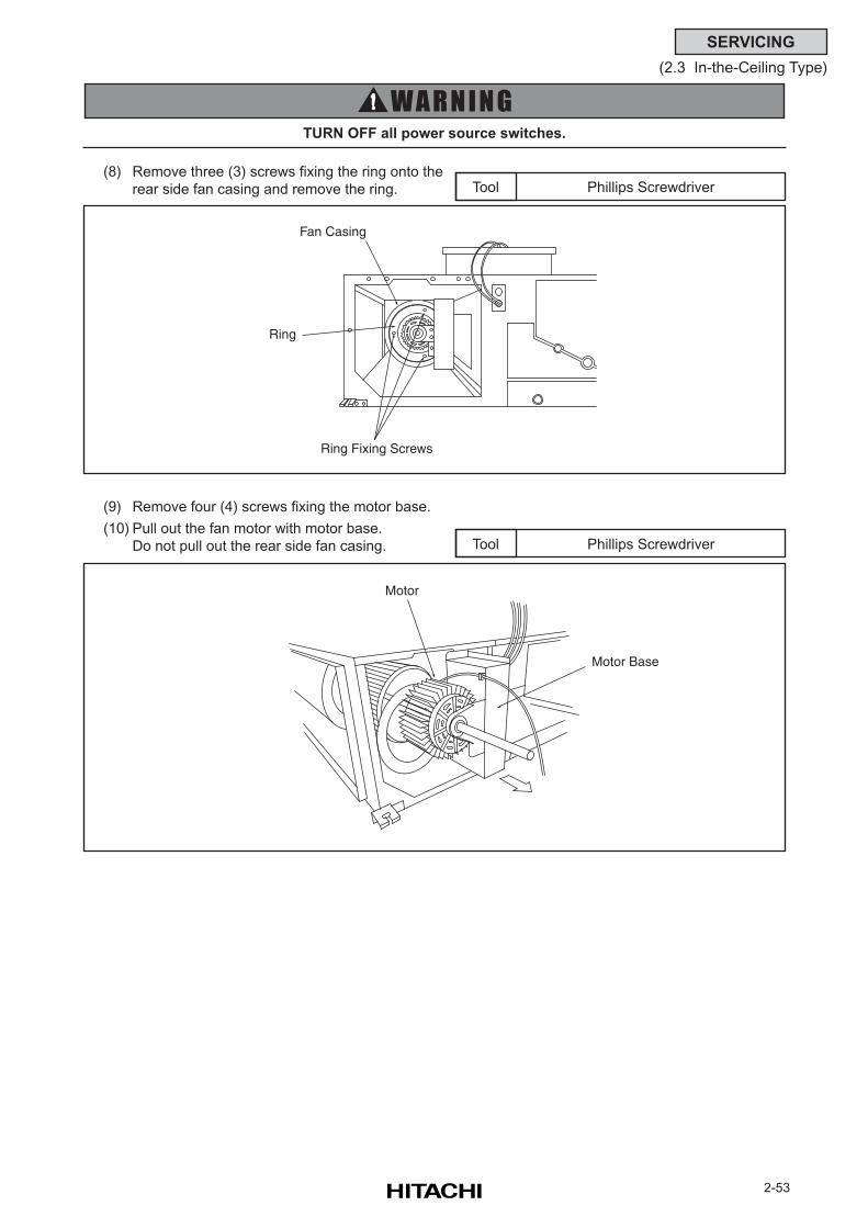
2-53
SERVICING
(2.3 In-the-Ceiling Type)
(8) Remove three (3) screws fixing the ring onto the
rear side fan casing and remove the ring. Phillips ScrewdriverTool
(9) Remove four (4) screws fixing the motor base.
(10) Pull out the fan motor with motor base.
Do not pull out the rear side fan casing. Phillips ScrewdriverTool
TURN OFF all power source switches.
Ring Fixing Screws
Fan Casing
Ring
Motor
Motor Base
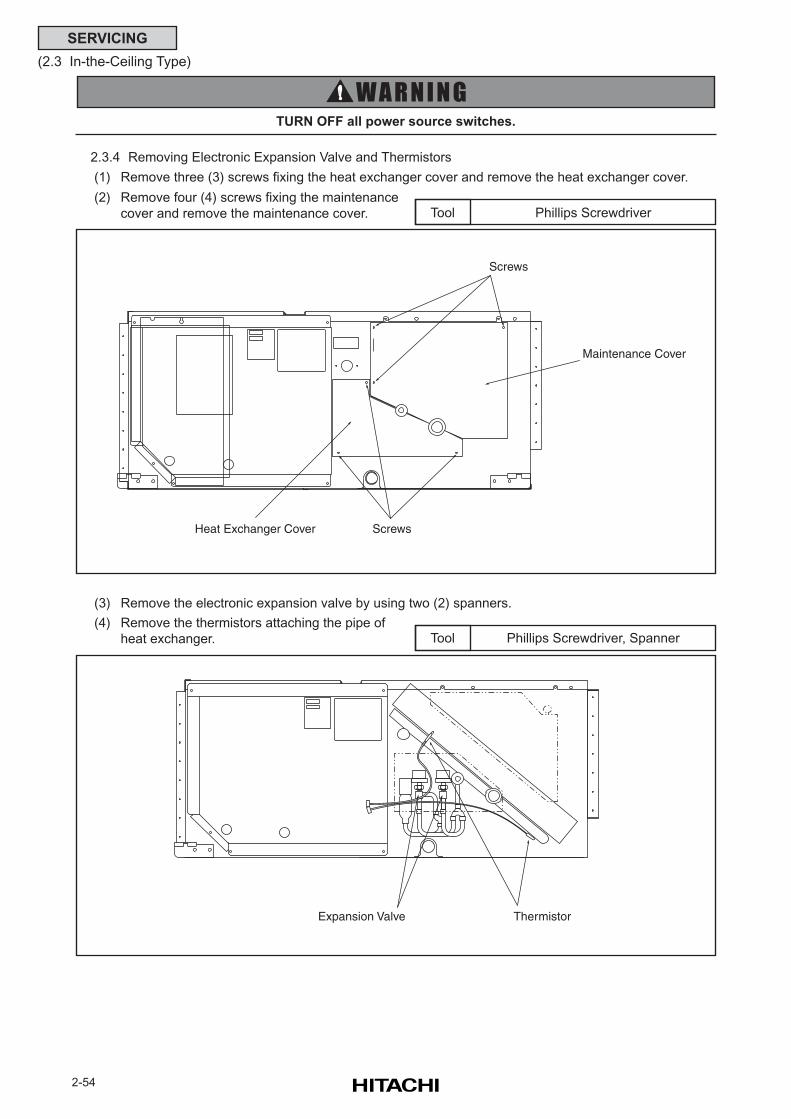
2-54
SERVICING
(2.3 In-the-Ceiling Type)
2.3.4 Removing Electronic Expansion Valve and Thermistors
(1) Remove three (3) screws fixing the heat exchanger cover and remove the heat exchanger cover.
(2) Remove four (4) screws fixing the maintenance
cover and remove the maintenance cover. Phillips ScrewdriverTool
TURN OFF all power source switches.
(3) Remove the electronic expansion valve by using two (2) spanners.
(4) Remove the thermistors attaching the pipe of
heat exchanger. Phillips Screwdriver, SpannerTool
Maintenance Cover
Screws
Heat Exchanger Cover Screws
ThermistorExpansion Valve
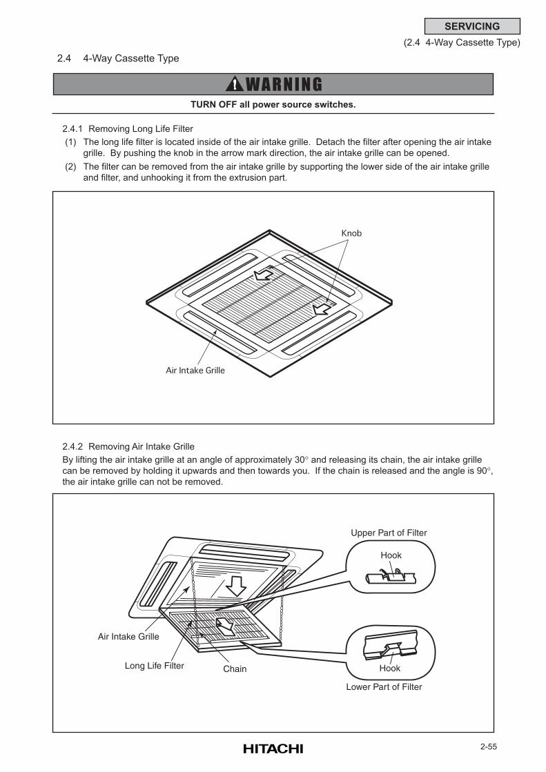
2-55
SERVICING
(2.4 4-Way Cassette Type)
2.4 4-Way Cassette Type
2.4.1 Removing Long Life Filter
(1) The long life filter is located inside of the air intake grille. Detach the filter after opening the air intake
grille. By pushing the knob in the arrow mark direction, the air intake grille can be opened.
(2) The filter can be removed from the air intake grille by supporting the lower side of the air intake grille
and filter, and unhooking it from the extrusion part.
2.4.2 Removing Air Intake Grille
By lifting the air intake grille at an angle of approximately 30° and releasing its chain, the air intake grille
can be removed by holding it upwards and then towards you. If the chain is released and the angle is 90°,the air intake grille can not be removed.
Knob
Air Intake Grille
TURN OFF all power source switches.
Upper Part of Filter
Hook
Hook
Lower Part of Filter
Long Life Filter
Air Intake Grille
Chain
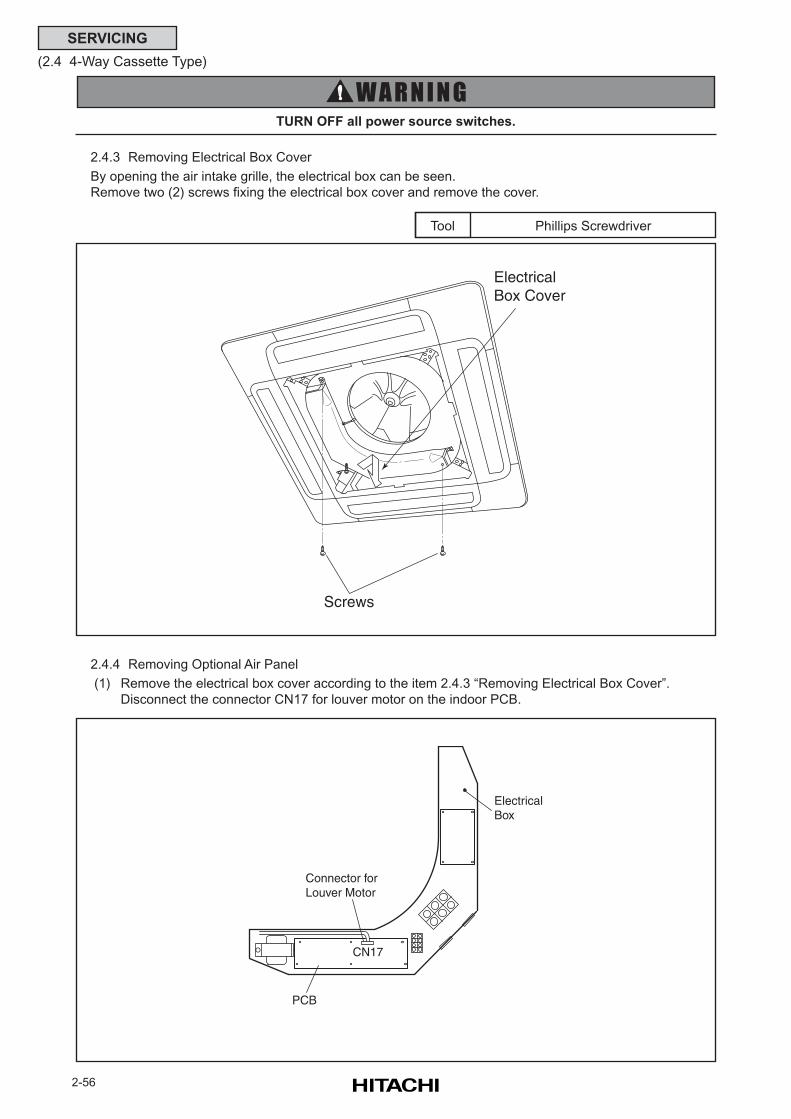
2-56
SERVICING
(2.4 4-Way Cassette Type)
2.4.3 Removing Electrical Box Cover
By opening the air intake grille, the electrical box can be seen.
Remove two (2) screws fixing the electrical box cover and remove the cover.
Phillips ScrewdriverTool
TURN OFF all power source switches.
Electrical Box Cover
Screws
2.4.4 Removing Optional Air Panel
(1) Remove the electrical box cover according to the item 2.4.3 “Removing Electrical Box Cover”.
Disconnect the connector CN17 for louver motor on the indoor PCB.
PCB
Connector forLouver Motor
CN17
ElectricalBox
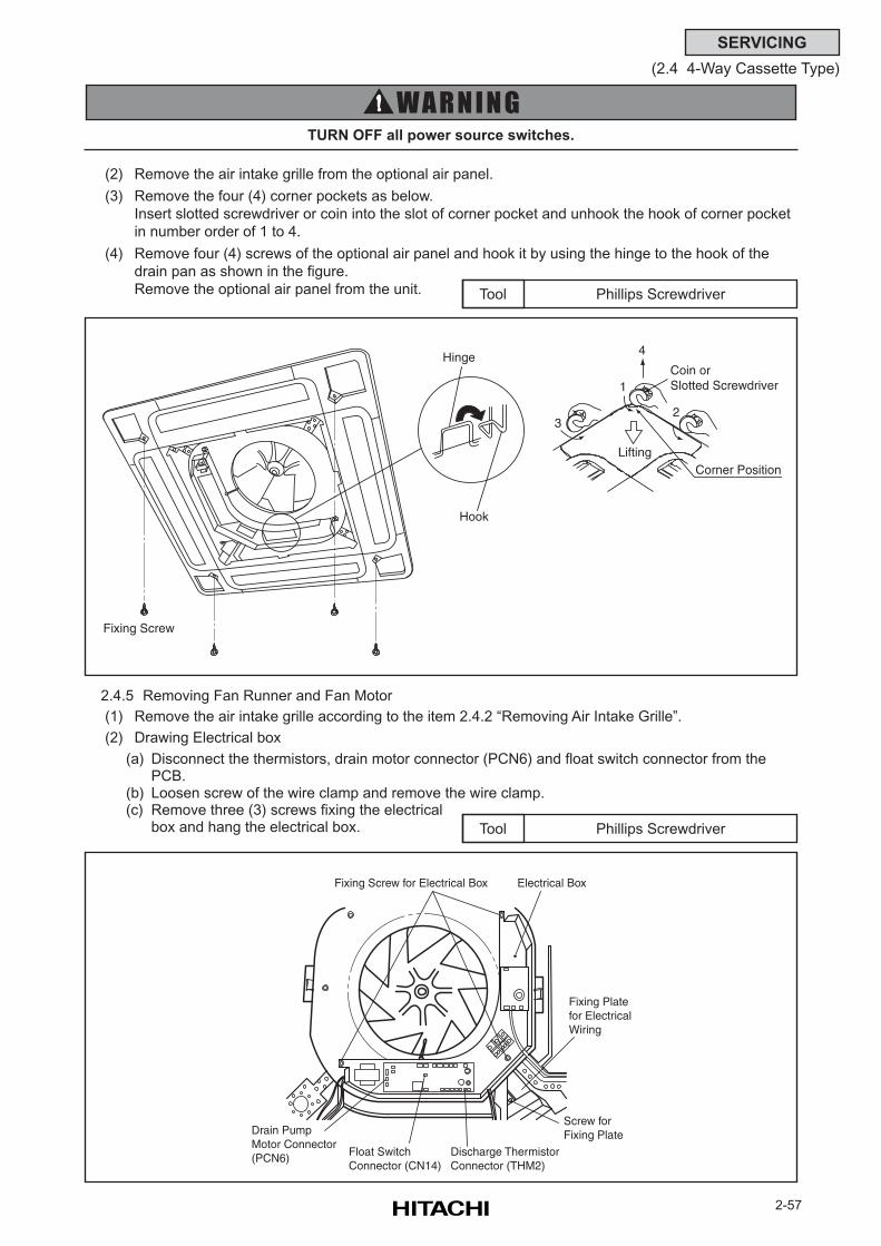
2-57
SERVICING
(2.4 4-Way Cassette Type)
(2) Remove the air intake grille from the optional air panel.
(3) Remove the four (4) corner pockets as below.
Insert slotted screwdriver or coin into the slot of corner pocket and unhook the hook of corner pocket
in number order of 1 to 4.
(4) Remove four (4) screws of the optional air panel and hook it by using the hinge to the hook of the
drain pan as shown in the figure.
Remove the optional air panel from the unit. Phillips ScrewdriverTool
Hinge
Hook
Fixing Screw
Lifting
Coin or Slotted Screwdriver
Corner Position
1
23
4
2.4.5 Removing Fan Runner and Fan Motor
(1) Remove the air intake grille according to the item 2.4.2 “Removing Air Intake Grille”.
(2) Drawing Electrical box
(a) Disconnect the thermistors, drain motor connector (PCN6) and float switch connector from thePCB.
(b) Loosen screw of the wire clamp and remove the wire clamp.(c) Remove three (3) screws fixing the electrical
box and hang the electrical box. Phillips ScrewdriverTool
Drain PumpMotor Connector(PCN6) Float Switch
Connector (CN14)Discharge ThermistorConnector (THM2)
Fixing Screw for Electrical Box Electrical Box
Screw for Fixing Plate
Fixing Platefor ElectricalWiring
TURN OFF all power source switches.
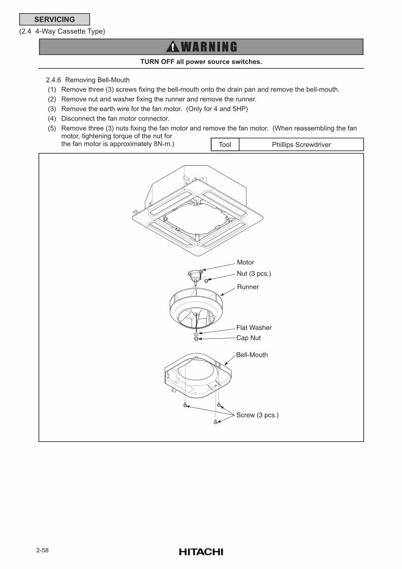
2-58
SERVICING
(2.4 4-Way Cassette Type)
2.4.6 Removing Bell-Mouth
(1) Remove three (3) screws fixing the bell-mouth onto the drain pan and remove the bell-mouth.
(2) Remove nut and washer fixing the runner and remove the runner.
(3) Remove the earth wire for the fan motor. (Only for 4 and 5HP)
(4) Disconnect the fan motor connector.
(5) Remove three (3) nuts fixing the fan motor and remove the fan motor. (When reassembling the fanmotor, tightening torque of the nut forthe fan motor is approximately 8N-m.)
TURN OFF all power source switches.
Phillips ScrewdriverTool
Motor
Nut (3 pcs.)
Runner
Bell-Mouth
Screw (3 pcs.)
Cap Nut
Flat Washer
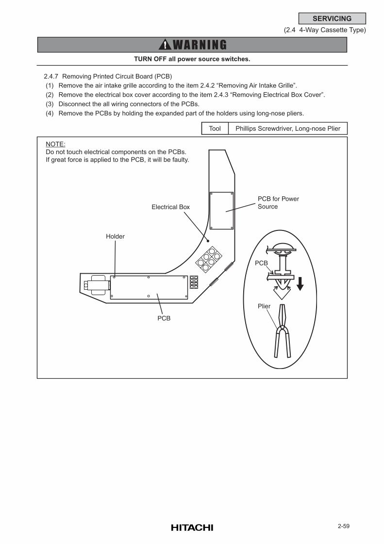
2-59
SERVICING
(2.4 4-Way Cassette Type)
2.4.7 Removing Printed Circuit Board (PCB)
(1) Remove the air intake grille according to the item 2.4.2 “Removing Air Intake Grille”.
(2) Remove the electrical box cover according to the item 2.4.3 “Removing Electrical Box Cover”.
(3) Disconnect the all wiring connectors of the PCBs.
(4) Remove the PCBs by holding the expanded part of the holders using long-nose pliers.
Phillips Screwdriver, Long-nose PlierTool
NOTE:
Do not touch electrical components on the PCBs.
If great force is applied to the PCB, it will be faulty.
Holder
Electrical BoxPCB for PowerSource
PCB
PCB
Plier
TURN OFF all power source switches.
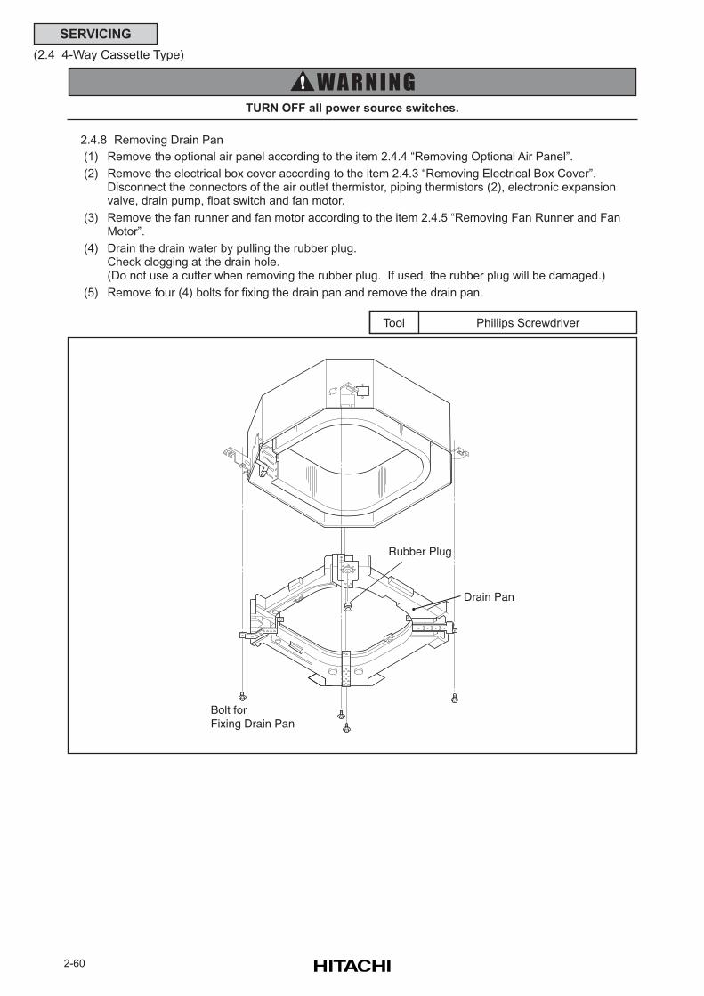
2-60
SERVICING
(2.4 4-Way Cassette Type)
2.4.8 Removing Drain Pan
(1) Remove the optional air panel according to the item 2.4.4 “Removing Optional Air Panel”.
(2) Remove the electrical box cover according to the item 2.4.3 “Removing Electrical Box Cover”.Disconnect the connectors of the air outlet thermistor, piping thermistors (2), electronic expansionvalve, drain pump, float switch and fan motor.
(3) Remove the fan runner and fan motor according to the item 2.4.5 “Removing Fan Runner and FanMotor”.
(4) Drain the drain water by pulling the rubber plug.Check clogging at the drain hole.(Do not use a cutter when removing the rubber plug. If used, the rubber plug will be damaged.)
(5) Remove four (4) bolts for fixing the drain pan and remove the drain pan.
TURN OFF all power source switches.
Phillips ScrewdriverTool
Rubber Plug
Drain Pan
Bolt for Fixing Drain Pan
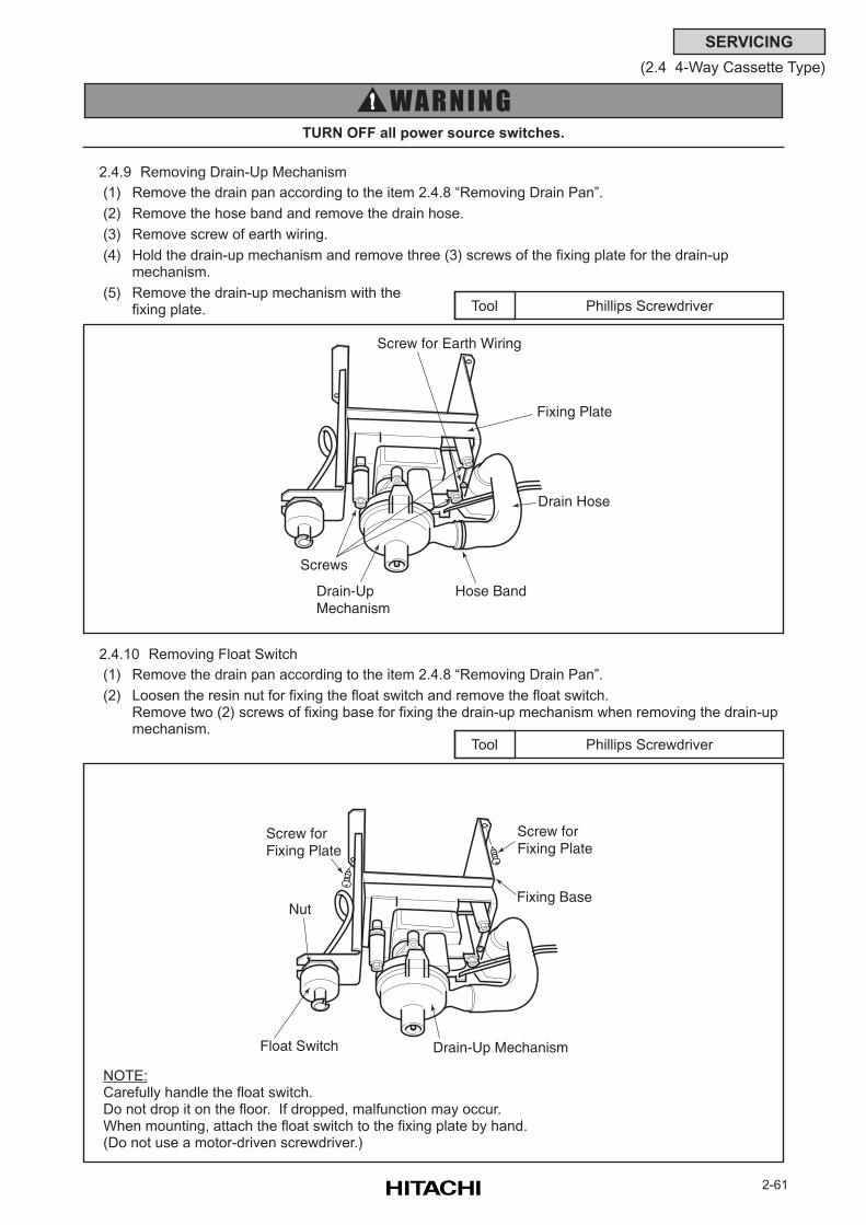
2-61
SERVICING
(2.4 4-Way Cassette Type)
2.4.9 Removing Drain-Up Mechanism
(1) Remove the drain pan according to the item 2.4.8 “Removing Drain Pan”.
(2) Remove the hose band and remove the drain hose.
(3) Remove screw of earth wiring.
(4) Hold the drain-up mechanism and remove three (3) screws of the fixing plate for the drain-upmechanism.
(5) Remove the drain-up mechanism with thefixing plate. Phillips ScrewdriverTool
2.4.10 Removing Float Switch
(1) Remove the drain pan according to the item 2.4.8 “Removing Drain Pan”.
(2) Loosen the resin nut for fixing the float switch and remove the float switch.Remove two (2) screws of fixing base for fixing the drain-up mechanism when removing the drain-upmechanism.
Phillips ScrewdriverTool
NOTE:Carefully handle the float switch.Do not drop it on the floor. If dropped, malfunction may occur.When mounting, attach the float switch to the fixing plate by hand.(Do not use a motor-driven screwdriver.)
Screw for Earth Wiring
Fixing Plate
Drain Hose
Hose Band
Screws
Drain-UpMechanism
Screw for Fixing Plate
Fixing BaseNut
Float Switch Drain-Up Mechanism
Screw for Fixing Plate
TURN OFF all power source switches.
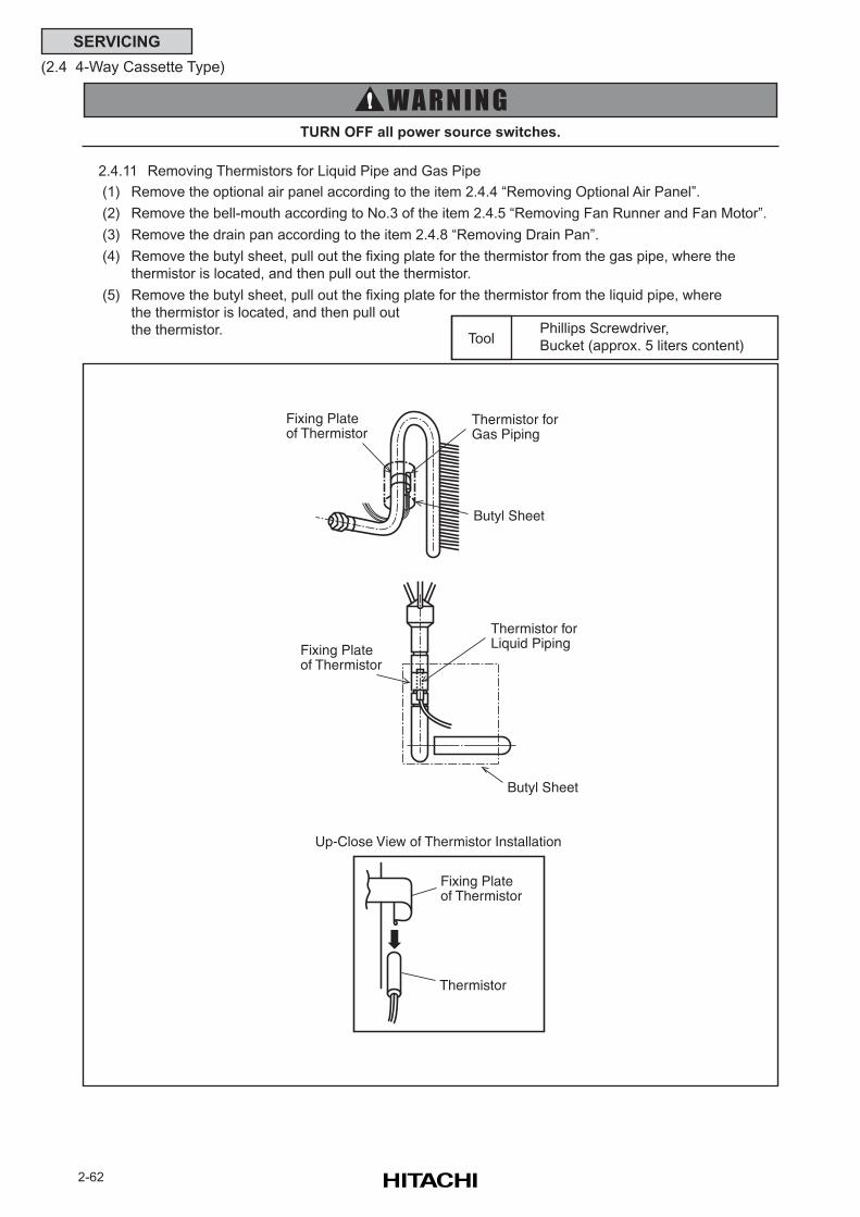
2-62
SERVICING
(2.4 4-Way Cassette Type)
TURN OFF all power source switches.
Phillips Screwdriver,
Bucket (approx. 5 liters content)Tool
2.4.11 Removing Thermistors for Liquid Pipe and Gas Pipe
(1) Remove the optional air panel according to the item 2.4.4 “Removing Optional Air Panel”.
(2) Remove the bell-mouth according to No.3 of the item 2.4.5 “Removing Fan Runner and Fan Motor”.
(3) Remove the drain pan according to the item 2.4.8 “Removing Drain Pan”.
(4) Remove the butyl sheet, pull out the fixing plate for the thermistor from the gas pipe, where the
thermistor is located, and then pull out the thermistor.
(5) Remove the butyl sheet, pull out the fixing plate for the thermistor from the liquid pipe, where
the thermistor is located, and then pull out
the thermistor.
Fixing Plateof Thermistor
Thermistor forGas Piping
Butyl Sheet
Fixing Plateof Thermistor
Thermistor forLiquid Piping
Butyl Sheet
Fixing Plateof Thermistor
Thermistor
Up-Close View of Thermistor Installation
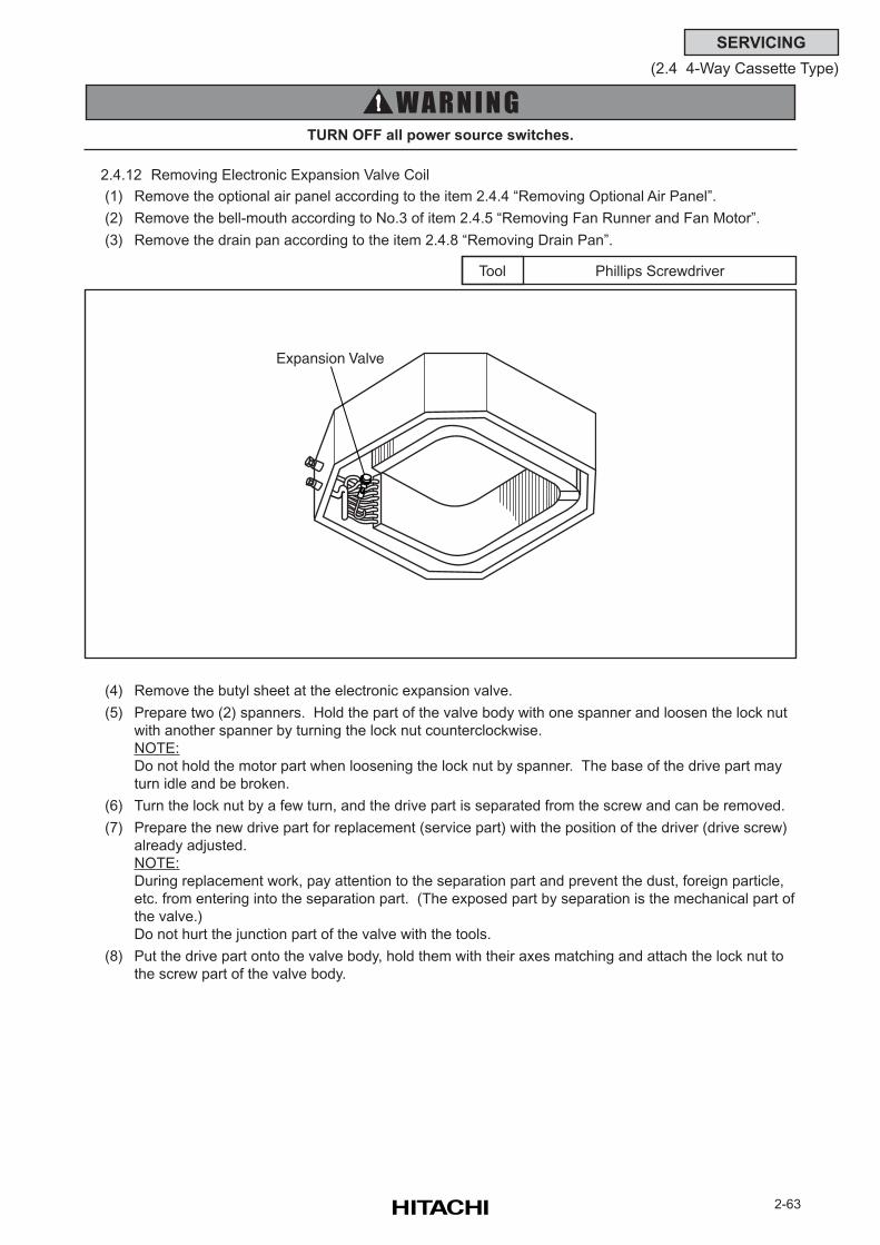
2-63
SERVICING
(2.4 4-Way Cassette Type)
2.4.12 Removing Electronic Expansion Valve Coil
(1) Remove the optional air panel according to the item 2.4.4 “Removing Optional Air Panel”.
(2) Remove the bell-mouth according to No.3 of item 2.4.5 “Removing Fan Runner and Fan Motor”.
(3) Remove the drain pan according to the item 2.4.8 “Removing Drain Pan”.
Phillips ScrewdriverTool
(4) Remove the butyl sheet at the electronic expansion valve.
(5) Prepare two (2) spanners. Hold the part of the valve body with one spanner and loosen the lock nut
with another spanner by turning the lock nut counterclockwise.
NOTE:
Do not hold the motor part when loosening the lock nut by spanner. The base of the drive part may
turn idle and be broken.
(6) Turn the lock nut by a few turn, and the drive part is separated from the screw and can be removed.
(7) Prepare the new drive part for replacement (service part) with the position of the driver (drive screw)
already adjusted.
NOTE:
During replacement work, pay attention to the separation part and prevent the dust, foreign particle,
etc. from entering into the separation part. (The exposed part by separation is the mechanical part of
the valve.)
Do not hurt the junction part of the valve with the tools.
(8) Put the drive part onto the valve body, hold them with their axes matching and attach the lock nut to
the screw part of the valve body.
TURN OFF all power source switches.
Expansion Valve
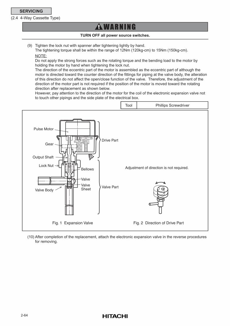
2-64
SERVICING
(2.4 4-Way Cassette Type)
TURN OFF all power source switches.
Phillips ScrewdriverTool
(9) Tighten the lock nut with spanner after tightening lightly by hand.
The tightening torque shall be within the range of 12Nm (120kg-cm) to 15Nm (150kg-cm).
NOTE:
Do not apply the strong forces such as the rotating torque and the bending load to the motor by
holding the motor by hand when tightening the lock nut.
The direction of the eccentric part of the motor is assembled as the eccentric part of although the
motor is directed toward the counter direction of the fittings for piping at the valve body, the alteration
of this direction do not affect the open/close function of the valve. Therefore, the adjustment of the
direction of the motor part is not required if the position of the motor is moved toward the rotating
direction after replacement as shown below.
However, pay attention to the direction of the motor for the coil of the electronic expansion valve not
to touch other pipings and the side plate of the electrical box.
(10) After completion of the replacement, attach the electronic expansion valve in the reverse procedures
for removing.
Pulse Motor
Gear
Output Shaft
Lock Nut
Valve BodyValve Sheet
Valve
Valve Part
Drive Part
Bellows
Fig. 1 Expansion Valve Fig. 2 Direction of Drive Part
Adjustment of direction is not required.
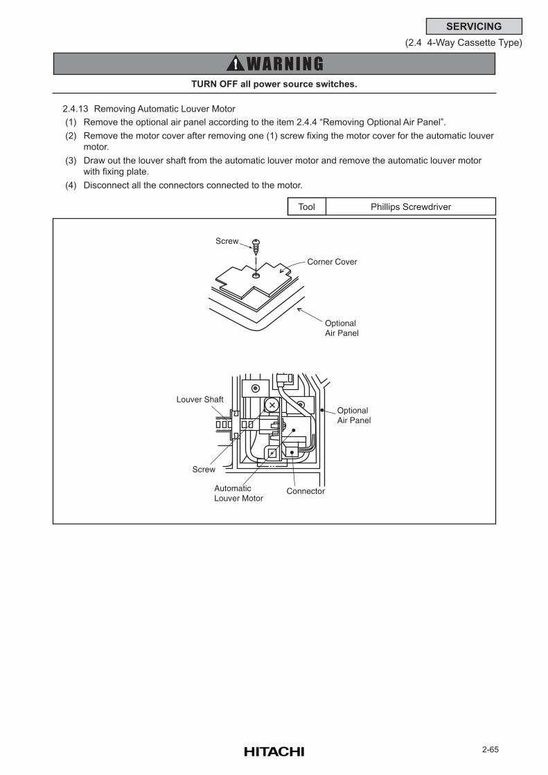
2-65
SERVICING
(2.4 4-Way Cassette Type)
2.4.13 Removing Automatic Louver Motor
(1) Remove the optional air panel according to the item 2.4.4 “Removing Optional Air Panel”.
(2) Remove the motor cover after removing one (1) screw fixing the motor cover for the automatic louver
motor.
(3) Draw out the louver shaft from the automatic louver motor and remove the automatic louver motor
with fixing plate.
(4) Disconnect all the connectors connected to the motor.
Phillips ScrewdriverTool
Screw
Corner Cover
Optional Air Panel
Louver Shaft
ConnectorAutomaticLouver Motor
Optional Air Panel
Screw
TURN OFF all power source switches.
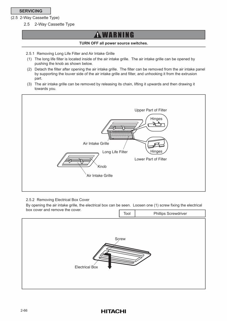
2-66
SERVICING
(2.5 2-Way Cassette Type)
2.5 2-Way Cassette Type
TURN OFF all power source switches.
2.5.1 Removing Long Life Filter and Air Intake Grille
(1) The long life filter is located inside of the air intake grille. The air intake grille can be opened by
pushing the knob as shown below.
(2) Detach the filter after opening the air intake grille. The filter can be removed from the air intake panel
by supporting the louver side of the air intake grille and filter, and unhooking it from the extrusion
part.
(3) The air intake grille can be removed by releasing its chain, lifting it upwards and then drawing it
towards you.
2.5.2 Removing Electrical Box Cover
By opening the air intake grille, the electrical box can be seen. Loosen one (1) screw fixing the electrical
box cover and remove the cover.Phillips ScrewdriverTool
Long Life Filter
Air Intake Grille
Knob
Upper Part of Filter
Lower Part of Filter
Air Intake Grille
Hinges
Hinges
Screw
Electrical Box
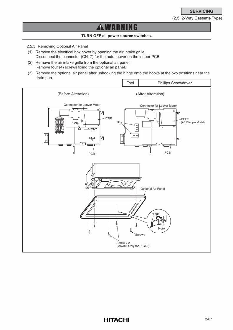
2-67
SERVICING
(2.5 2-Way Cassette Type)
2.5.3 Removing Optional Air Panel
(1) Remove the electrical box cover by opening the air intake grille.
Disconnect the connector (CN17) for the auto-louver on the indoor PCB.
(2) Remove the air intake grille from the optional air panel.
Remove four (4) screws fixing the optional air panel.
(3) Remove the optional air panel after unhooking the hinge onto the hooks at the two positions near the
drain pan.
Phillips ScrewdriverTool
TURN OFF all power source switches.
Hinge
Hook
Connector for Louver Motor
PCB
CN4
CN7
PCN4
Optional Air Panel
Screws
Screw x 2(M6x30, Only for P-G46)
PCB2
(Before Alteration)
Connector for Louver Motor
PCB2(AC Chopper Model)
(After Alteration)
PCB
TB
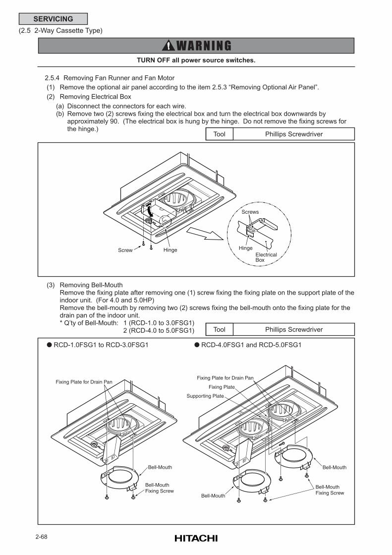
2-68
SERVICING
(2.5 2-Way Cassette Type)
2.5.4 Removing Fan Runner and Fan Motor
(1) Remove the optional air panel according to the item 2.5.3 “Removing Optional Air Panel”.
(2) Removing Electrical Box
(a) Disconnect the connectors for each wire.(b) Remove two (2) screws fixing the electrical box and turn the electrical box downwards by
approximately 90. (The electrical box is hung by the hinge. Do not remove the fixing screws forthe hinge.)
TURN OFF all power source switches.
Phillips ScrewdriverTool
(3) Removing Bell-MouthRemove the fixing plate after removing one (1) screw fixing the fixing plate on the support plate of theindoor unit. (For 4.0 and 5.0HP)Remove the bell-mouth by removing two (2) screws fixing the bell-mouth onto the fixing plate for thedrain pan of the indoor unit.* Q’ty of Bell-Mouth: 1 (RCD-1.0 to 3.0FSG1)
2 (RCD-4.0 to 5.0FSG1) Phillips ScrewdriverTool
RCD-4.0FSG1 and RCD-5.0FSG1 RCD-1.0FSG1 to RCD-3.0FSG1
Fixing Plate for Drain Pan
Bell-Mouth
Bell-MouthFixing Screw
Bell-Mouth
Bell-MouthFixing Screw
Fixing Plate for Drain Pan
Bell-Mouth
Supporting Plate
Fixing Plate
HingeScrew Hinge
Screws
ElectricalBox

2-69
SERVICING
(2.5 2-Way Cassette Type)
Phillips Screwdriver, SpannerTool
(4) Remove the fan runner and the fan motor.
Remove the fan runner after removing the cap nut and the washer fixing the fan runner.
(a) Disconnect the earth wire for the fan motor.
(b) Remove four (4) nuts fixing the fan motor and remove the fan motor.
(When reassembling, the required tightening torque for the cap nut is approximately
8N-m (80kg-cm).
* Q’ty of Fan Runner and Fan Motor: Each 1 (RCD-1.0 to 3.0FSG1)
Each 2 (RCD-4.0 to 5.0FSG1)
TURN OFF all power source switches.
Nut
Fan Motor
Earth
Runner
Flat Washer
Cap Nut
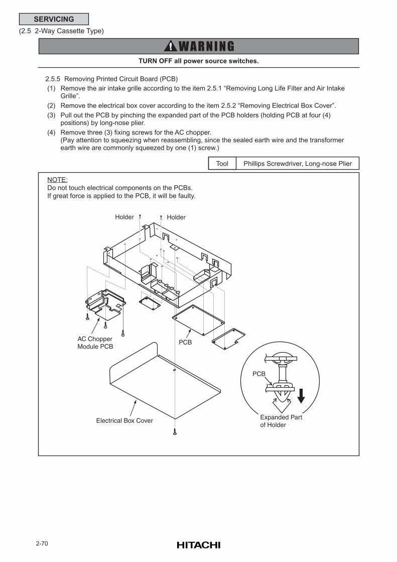
2-70
SERVICING
(2.5 2-Way Cassette Type)
2.5.5 Removing Printed Circuit Board (PCB)
(1) Remove the air intake grille according to the item 2.5.1 “Removing Long Life Filter and Air IntakeGrille”.
(2) Remove the electrical box cover according to the item 2.5.2 “Removing Electrical Box Cover”.
(3) Pull out the PCB by pinching the expanded part of the PCB holders (holding PCB at four (4)positions) by long-nose plier.
(4) Remove three (3) fixing screws for the AC chopper.(Pay attention to squeezing when reassembling, since the sealed earth wire and the transformerearth wire are commonly squeezed by one (1) screw.)
TURN OFF all power source switches.
Phillips Screwdriver, Long-nose PlierTool
NOTE:
Do not touch electrical components on the PCBs.
If great force is applied to the PCB, it will be faulty.
PCB
Expanded Partof Holder
AC ChopperModule PCB
PCB
Holder
Electrical Box Cover
Holder
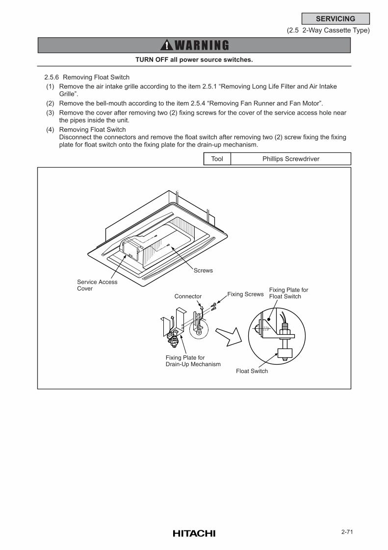
2-71
SERVICING
(2.5 2-Way Cassette Type)
2.5.6 Removing Float Switch
(1) Remove the air intake grille according to the item 2.5.1 “Removing Long Life Filter and Air IntakeGrille”.
(2) Remove the bell-mouth according to the item 2.5.4 “Removing Fan Runner and Fan Motor”.
(3) Remove the cover after removing two (2) fixing screws for the cover of the service access hole nearthe pipes inside the unit.
(4) Removing Float SwitchDisconnect the connectors and remove the float switch after removing two (2) screw fixing the fixingplate for float switch onto the fixing plate for the drain-up mechanism.
Phillips ScrewdriverTool
TURN OFF all power source switches.
Service AccessCover
Fixing ScrewsConnector
Screws
Fixing Plate forDrain-Up Mechanism
Float Switch
Fixing Plate forFloat Switch
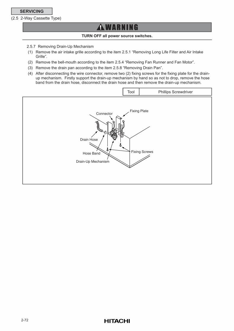
2-72
SERVICING
(2.5 2-Way Cassette Type)
2.5.7 Removing Drain-Up Mechanism
(1) Remove the air intake grille according to the item 2.5.1 “Removing Long Life Filter and Air IntakeGrille”.
(2) Remove the bell-mouth according to the item 2.5.4 “Removing Fan Runner and Fan Motor”.
(3) Remove the drain pan according to the item 2.5.8 “Removing Drain Pan”.
(4) After disconnecting the wire connector, remove two (2) fixing screws for the fixing plate for the drain-up mechanism. Firstly support the drain-up mechanism by hand so as not to drop, remove the hoseband from the drain hose, disconnect the drain hose and then remove the drain-up mechanism.
TURN OFF all power source switches.
Phillips ScrewdriverTool
Fixing Screws
ConnectorFixing Plate
Drain-Up Mechanism
Drain Hose
Hose Band
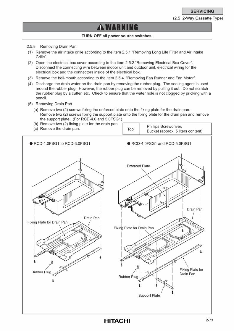
2-73
SERVICING
(2.5 2-Way Cassette Type)
Phillips Screwdriver,
Bucket (approx. 5 liters content)Tool
2.5.8 Removing Drain Pan
(1) Remove the air intake grille according to the item 2.5.1 “Removing Long Life Filter and Air Intake
Grille”.
(2) Open the electrical box cover according to the item 2.5.2 “Removing Electrical Box Cover”.
Disconnect the connecting wire between indoor unit and outdoor unit, electrical wiring for the
electrical box and the connectors inside of the electrical box.
(3) Remove the bell-mouth according to the item 2.5.4 “Removing Fan Runner and Fan Motor”.
(4) Discharge the drain water on the drain pan by removing the rubber plug. The sealing agent is used
around the rubber plug. However, the rubber plug can be removed by pulling it out. Do not scratch
the rubber plug by a cutter, etc. Check to ensure that the water hole is not clogged by pricking with a
pencil.
(5) Removing Drain Pan
(a) Remove two (2) screws fixing the enforced plate onto the fixing plate for the drain pan.
Remove two (2) screws fixing the support plate onto the fixing plate for the drain pan and remove
the support plate. (For RCD-4.0 and 5.0FSG1)
(b) Remove two (2) fixing plate for the drain pan.
(c) Remove the drain pan.
RCD-4.0FSG1 and RCD-5.0FSG1 RCD-1.0FSG1 to RCD-3.0FSG1
TURN OFF all power source switches.
Enforced Plate
Drain Pan
Fixing Plate for Drain Pan
Support Plate
Rubber PlugRubber Plug
Fixing Plate forDrain Pan
Fixing Plate for Drain PanDrain Pan
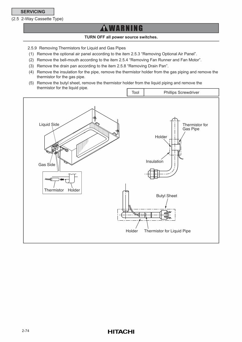
2-74
SERVICING
(2.5 2-Way Cassette Type)
2.5.9 Removing Thermistors for Liquid and Gas Pipes
(1) Remove the optional air panel according to the item 2.5.3 “Removing Optional Air Panel”.
(2) Remove the bell-mouth according to the item 2.5.4 “Removing Fan Runner and Fan Motor”.
(3) Remove the drain pan according to the item 2.5.8 “Removing Drain Pan”.
(4) Remove the insulation for the pipe, remove the thermistor holder from the gas piping and remove the
thermistor for the gas pipe.
(5) Remove the butyl sheet, remove the thermistor holder from the liquid piping and remove the
thermistor for the liquid pipe.
TURN OFF all power source switches.
Phillips ScrewdriverTool
Butyl Sheet
Thermistor for Liquid PipeHolder
Holder
Thermistor forGas Pipe
Insulation
Liquid Side
Thermistor Holder
Gas Side
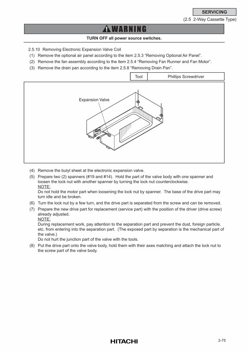
2-75
SERVICING
(2.5 2-Way Cassette Type)
2.5.10 Removing Electronic Expansion Valve Coil
(1) Remove the optional air panel according to the item 2.5.3 “Removing Optional Air Panel”.
(2) Remove the fan assembly according to the item 2.5.4 “Removing Fan Runner and Fan Motor”.
(3) Remove the drain pan according to the item 2.5.8 “Removing Drain Pan”.
Phillips ScrewdriverTool
(4) Remove the butyl sheet at the electronic expansion valve.
(5) Prepare two (2) spanners (#19 and #14). Hold the part of the valve body with one spanner and
loosen the lock nut with another spanner by turning the lock nut counterclockwise.
NOTE:
Do not hold the motor part when loosening the lock nut by spanner. The base of the drive part may
turn idle and be broken.
(6) Turn the lock nut by a few turn, and the drive part is separated from the screw and can be removed.
(7) Prepare the new drive part for replacement (service part) with the position of the driver (drive screw)
already adjusted.
NOTE:
During replacement work, pay attention to the separation part and prevent the dust, foreign particle,
etc. from entering into the separation part. (The exposed part by separation is the mechanical part of
the valve.)
Do not hurt the junction part of the valve with the tools.
(8) Put the drive part onto the valve body, hold them with their axes matching and attach the lock nut to
the screw part of the valve body.
TURN OFF all power source switches.
Expansion Valve
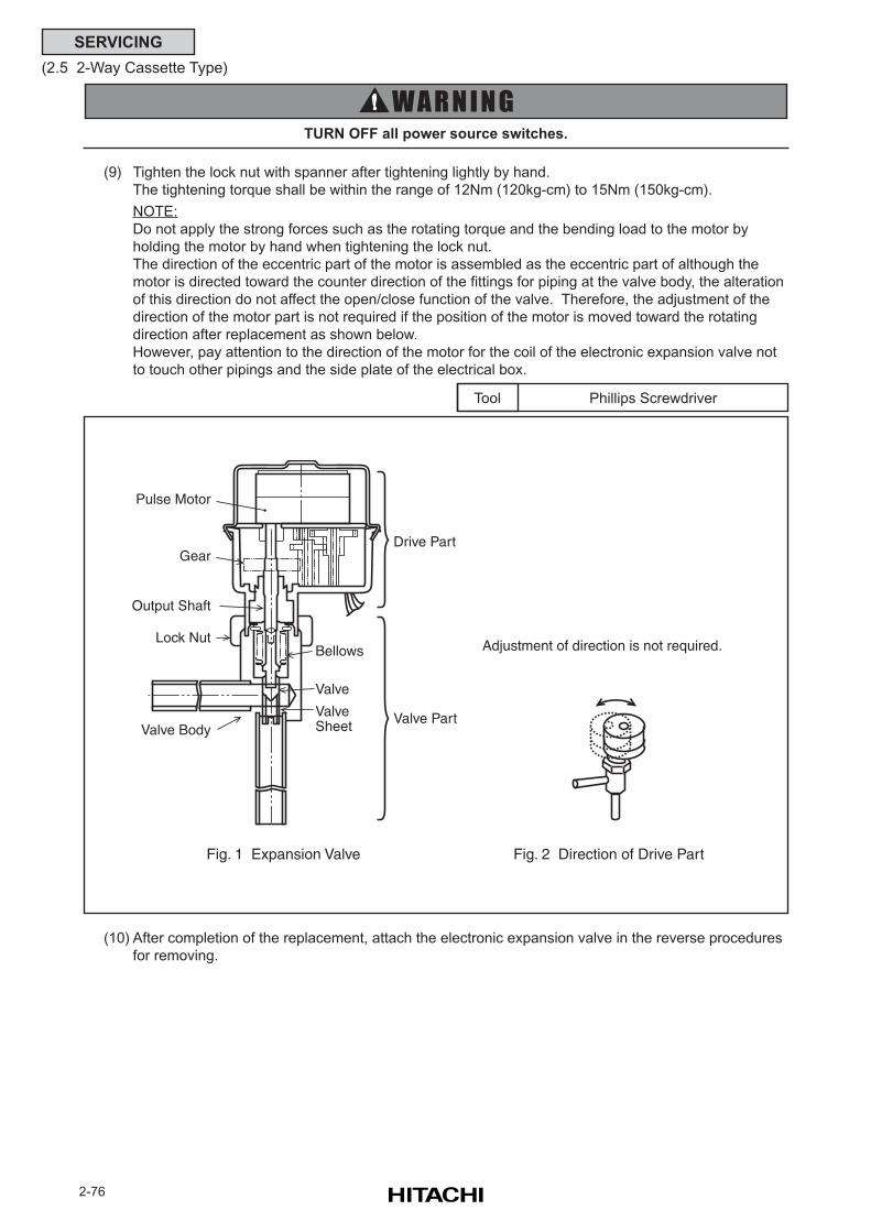
2-76
SERVICING
(2.5 2-Way Cassette Type)
TURN OFF all power source switches.
Phillips ScrewdriverTool
(9) Tighten the lock nut with spanner after tightening lightly by hand.
The tightening torque shall be within the range of 12Nm (120kg-cm) to 15Nm (150kg-cm).
NOTE:
Do not apply the strong forces such as the rotating torque and the bending load to the motor by
holding the motor by hand when tightening the lock nut.
The direction of the eccentric part of the motor is assembled as the eccentric part of although the
motor is directed toward the counter direction of the fittings for piping at the valve body, the alteration
of this direction do not affect the open/close function of the valve. Therefore, the adjustment of the
direction of the motor part is not required if the position of the motor is moved toward the rotating
direction after replacement as shown below.
However, pay attention to the direction of the motor for the coil of the electronic expansion valve not
to touch other pipings and the side plate of the electrical box.
(10) After completion of the replacement, attach the electronic expansion valve in the reverse procedures
for removing.
Pulse Motor
Gear
Output Shaft
Lock Nut
Valve BodyValve Sheet
Valve
Valve Part
Drive Part
Bellows
Fig. 1 Expansion Valve Fig. 2 Direction of Drive Part
Adjustment of direction is not required.
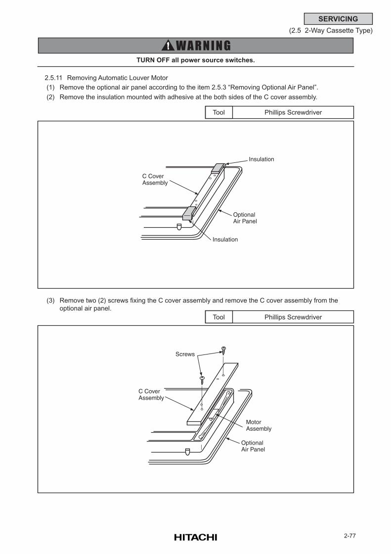
2-77
SERVICING
(2.5 2-Way Cassette Type)
2.5.11 Removing Automatic Louver Motor
(1) Remove the optional air panel according to the item 2.5.3 “Removing Optional Air Panel”.
(2) Remove the insulation mounted with adhesive at the both sides of the C cover assembly.
Phillips ScrewdriverTool
(3) Remove two (2) screws fixing the C cover assembly and remove the C cover assembly from the
optional air panel.
Phillips ScrewdriverTool
TURN OFF all power source switches.
C CoverAssembly
OptionalAir Panel
Insulation
Insulation
C CoverAssembly
OptionalAir Panel
Screws
MotorAssembly
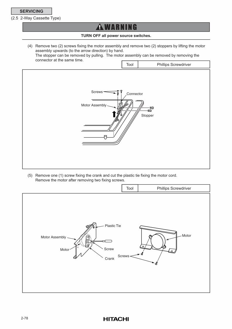
2-78
SERVICING
(2.5 2-Way Cassette Type)
(4) Remove two (2) screws fixing the motor assembly and remove two (2) stoppers by lifting the motor
assembly upwards (to the arrow direction) by hand.
The stopper can be removed by pulling. The motor assembly can be removed by removing the
connector at the same time.
TURN OFF all power source switches.
Phillips ScrewdriverTool
(5) Remove one (1) screw fixing the crank and cut the plastic tie fixing the motor cord.
Remove the motor after removing two fixing screws.
Phillips ScrewdriverTool
Motor Assembly
Connector
Stopper
Screws
Screw
Screws
MotorMotor Assembly
Crank
Plastic Tie
Motor
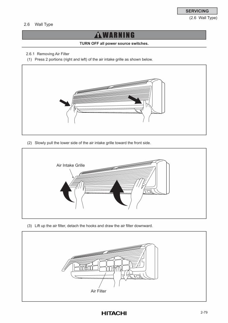
2-79
SERVICING
(2.6 Wall Type)
2.6 Wall Type
2.6.1 Removing Air Filter
(1) Press 2 portions (right and left) of the air intake grille as shown below.
TURN OFF all power source switches.
(2) Slowly pull the lower side of the air intake grille toward the front side.
(3) Lift up the air filter, detach the hooks and draw the air filter downward.
Air Intake Grille
Air Filter
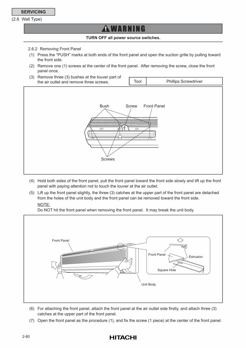
2-80
SERVICING
(2.6 Wall Type)
Phillips ScrewdriverTool
TURN OFF all power source switches.
(4) Hold both sides of the front panel, pull the front panel toward the front side slowly and lift up the front
panel with paying attention not to touch the louver at the air outlet.
(5) Lift up the front panel slightly, the three (3) catches at the upper part of the front panel are detached
from the holes of the unit body and the front panel can be removed toward the front side.
NOTE:
Do NOT hit the front panel when removing the front panel. It may break the unit body.
(6) For attaching the front panel, attach the front panel at the air outlet side firstly, and attach three (3)
catches at the upper part of the front panel.
(7) Open the front panel as the procedure (1), and fix the screw (1 piece) at the center of the front panel.
2.6.2 Removing Front Panel
(1) Press the “PUSH” marks at both ends of the front panel and open the suction grille by pulling toward
the front side.
(2) Remove one (1) screws at the center of the front panel. After removing the screw, close the front
panel once.
(3) Remove three (3) bushes at the louver part of
the air outlet and remove three screws.
Bush Screw
Screws
Front Panel
Front Panel
Extrusion
Square Hole
Front Panel
Unit Body
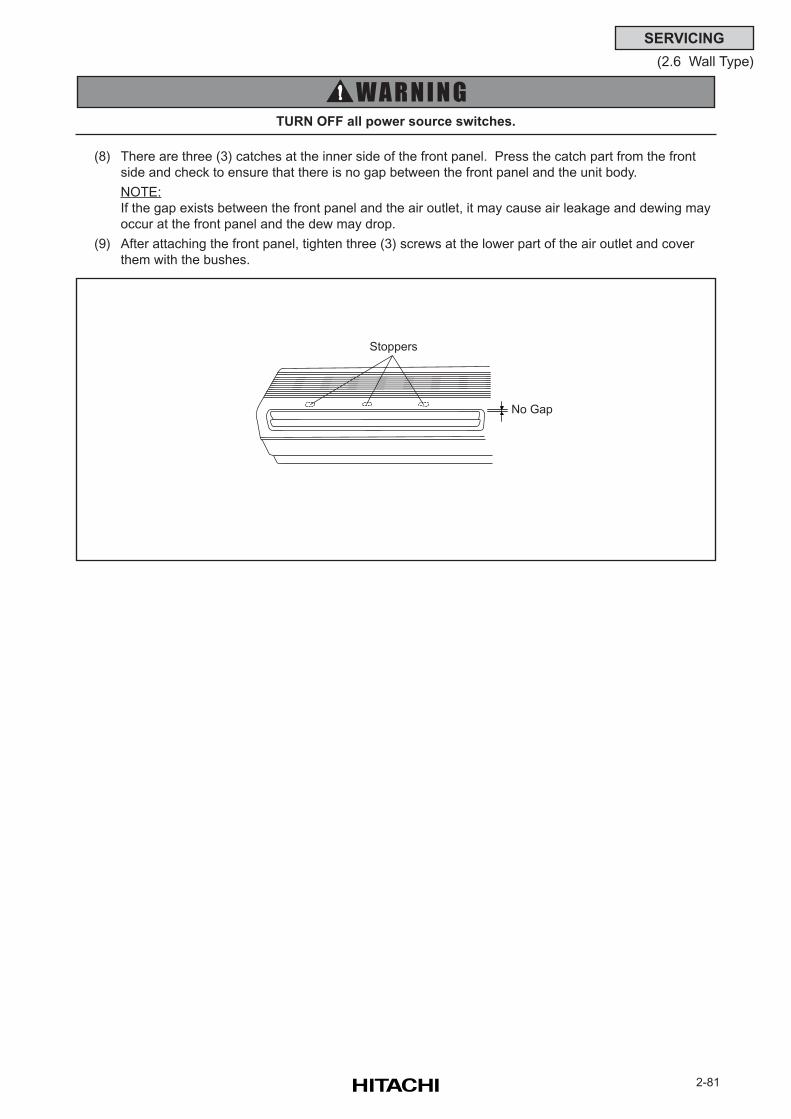
2-81
SERVICING
(2.6 Wall Type)
TURN OFF all power source switches.
(8) There are three (3) catches at the inner side of the front panel. Press the catch part from the front
side and check to ensure that there is no gap between the front panel and the unit body.
NOTE:
If the gap exists between the front panel and the air outlet, it may cause air leakage and dewing may
occur at the front panel and the dew may drop.
(9) After attaching the front panel, tighten three (3) screws at the lower part of the air outlet and cover
them with the bushes.
Stoppers
No Gap
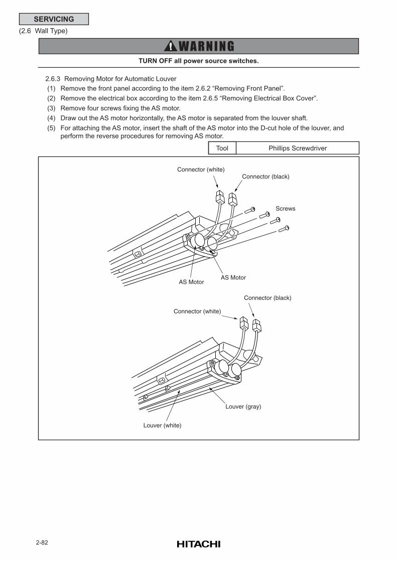
2-82
SERVICING
(2.6 Wall Type)
2.6.3 Removing Motor for Automatic Louver
(1) Remove the front panel according to the item 2.6.2 “Removing Front Panel”.
(2) Remove the electrical box according to the item 2.6.5 “Removing Electrical Box Cover”.
(3) Remove four screws fixing the AS motor.
(4) Draw out the AS motor horizontally, the AS motor is separated from the louver shaft.
(5) For attaching the AS motor, insert the shaft of the AS motor into the D-cut hole of the louver, and
perform the reverse procedures for removing AS motor.
TURN OFF all power source switches.
Phillips ScrewdriverTool
AS MotorAS Motor
Screws
Connector (white)Connector (black)
Connector (white)
Connector (black)
Louver (white)
Louver (gray)
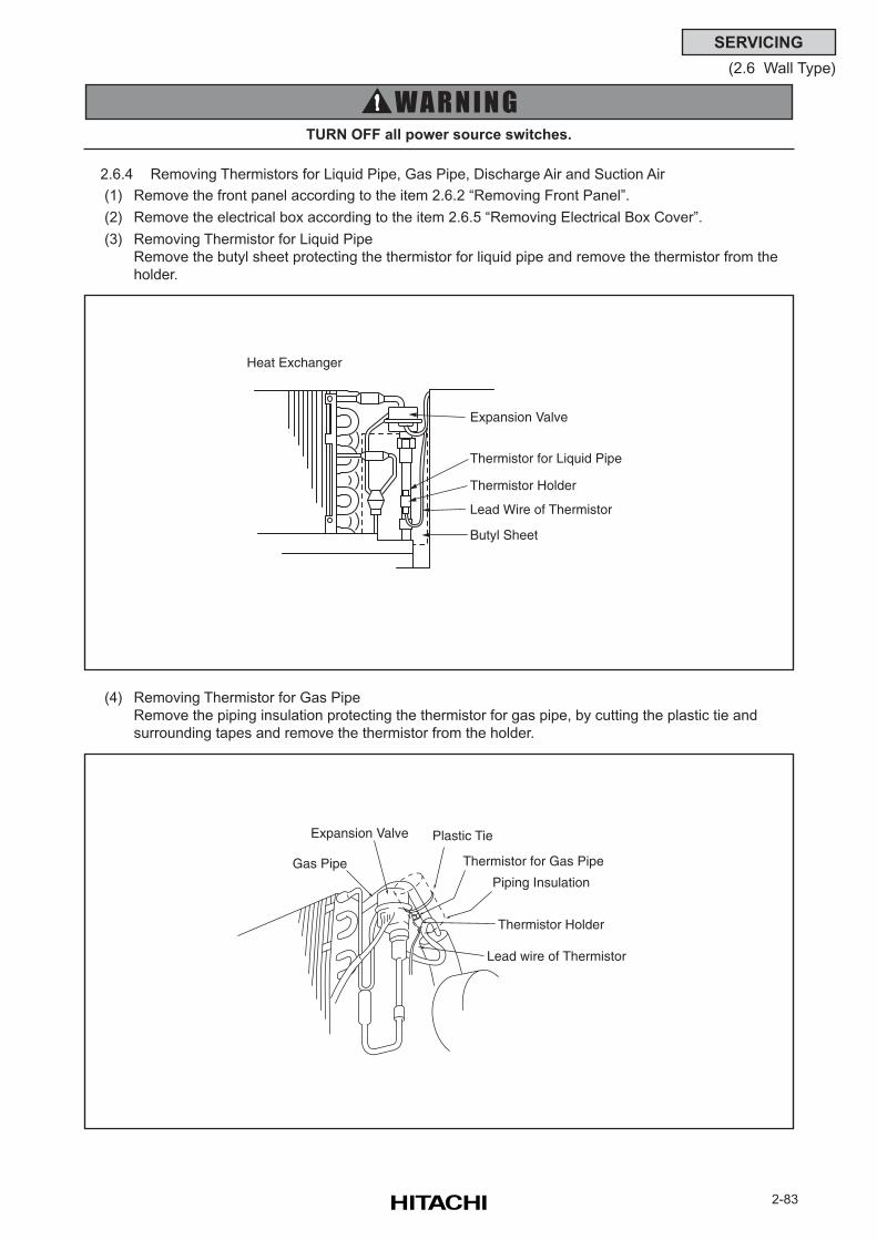
2-83
SERVICING
(2.6 Wall Type)
2.6.4 Removing Thermistors for Liquid Pipe, Gas Pipe, Discharge Air and Suction Air
(1) Remove the front panel according to the item 2.6.2 “Removing Front Panel”.
(2) Remove the electrical box according to the item 2.6.5 “Removing Electrical Box Cover”.
(3) Removing Thermistor for Liquid Pipe
Remove the butyl sheet protecting the thermistor for liquid pipe and remove the thermistor from the
holder.
TURN OFF all power source switches.
(4) Removing Thermistor for Gas Pipe
Remove the piping insulation protecting the thermistor for gas pipe, by cutting the plastic tie and
surrounding tapes and remove the thermistor from the holder.
Heat Exchanger
Expansion Valve
Thermistor for Liquid Pipe
Thermistor Holder
Lead Wire of Thermistor
Butyl Sheet
Gas Pipe
Expansion Valve Plastic Tie
Thermistor for Gas Pipe
Piping Insulation
Thermistor Holder
Lead wire of Thermistor
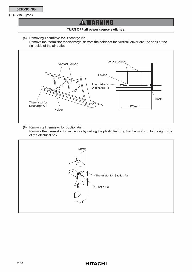
2-84
SERVICING
(2.6 Wall Type)
(5) Removing Thermistor for Discharge Air
Remove the thermistor for discharge air from the holder of the vertical louver and the hook at the
right side of the air outlet.
TURN OFF all power source switches.
(6) Removing Thermistor for Suction Air
Remove the thermistor for suction air by cutting the plastic tie fixing the thermistor onto the right side
of the electrical box.
Vertical Louver
Thermistor for Discharge Air
Holder
Hook
120mm
Thermistor for Discharge Air
Holder
Vertical Louver
Thermistor for Suction Air
Plastic Tie
20mm
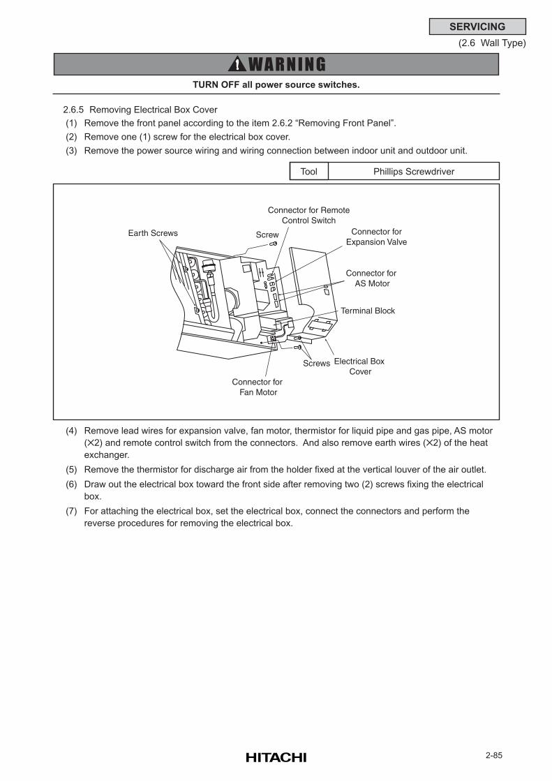
2-85
SERVICING
(2.6 Wall Type)
Phillips ScrewdriverTool
TURN OFF all power source switches.
(4) Remove lead wires for expansion valve, fan motor, thermistor for liquid pipe and gas pipe, AS motor
(2) and remote control switch from the connectors. And also remove earth wires (2) of the heat
exchanger.
(5) Remove the thermistor for discharge air from the holder fixed at the vertical louver of the air outlet.
(6) Draw out the electrical box toward the front side after removing two (2) screws fixing the electrical
box.
(7) For attaching the electrical box, set the electrical box, connect the connectors and perform the
reverse procedures for removing the electrical box.
2.6.5 Removing Electrical Box Cover
(1) Remove the front panel according to the item 2.6.2 “Removing Front Panel”.
(2) Remove one (1) screw for the electrical box cover.
(3) Remove the power source wiring and wiring connection between indoor unit and outdoor unit.
Earth Screws
Connector for Remote Control Switch
Connector forExpansion Valve
Connector for AS Motor
Electrical Box Cover
Connector for Fan Motor
Terminal Block
Screw
Screws
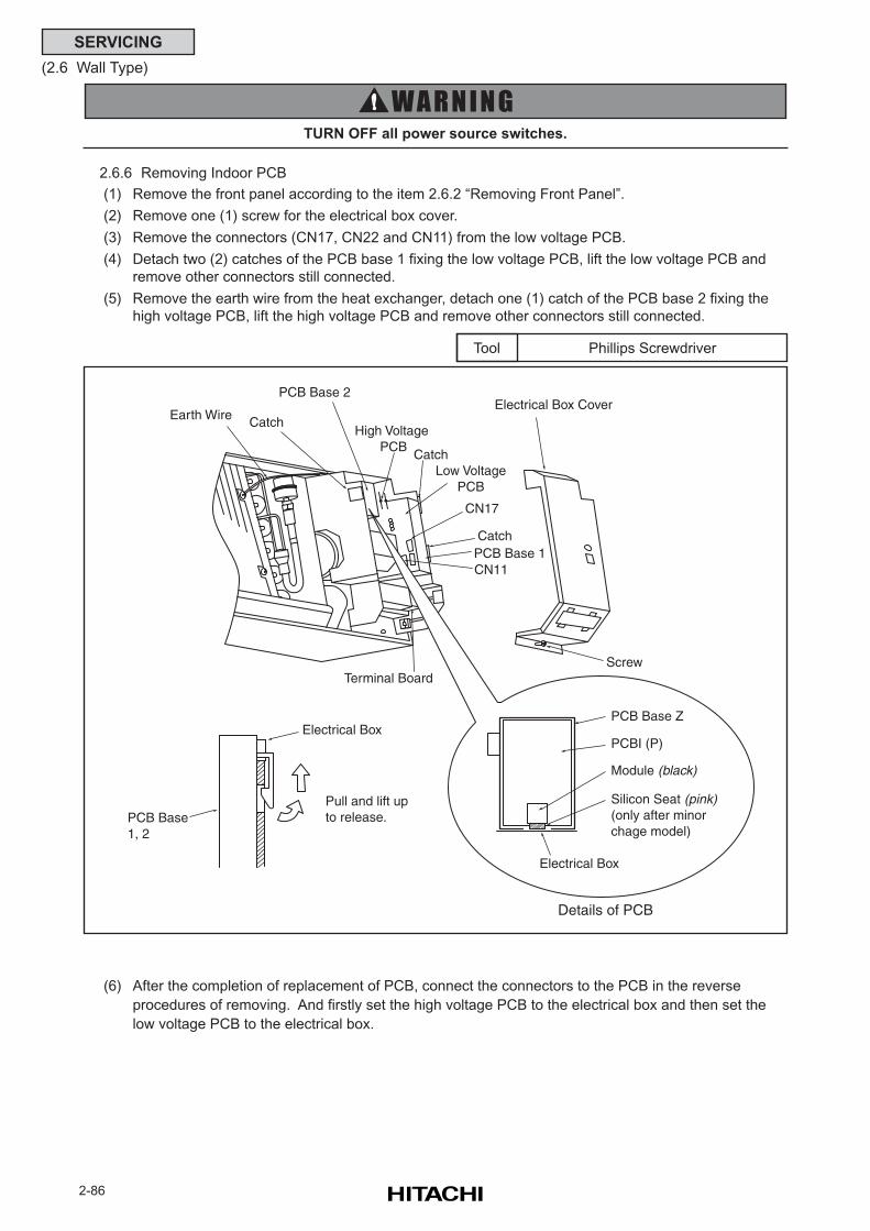
2-86
SERVICING
(2.6 Wall Type)
Phillips ScrewdriverTool
TURN OFF all power source switches.
(6) After the completion of replacement of PCB, connect the connectors to the PCB in the reverse
procedures of removing. And firstly set the high voltage PCB to the electrical box and then set the
low voltage PCB to the electrical box.
2.6.6 Removing Indoor PCB
(1) Remove the front panel according to the item 2.6.2 “Removing Front Panel”.
(2) Remove one (1) screw for the electrical box cover.
(3) Remove the connectors (CN17, CN22 and CN11) from the low voltage PCB.
(4) Detach two (2) catches of the PCB base 1 fixing the low voltage PCB, lift the low voltage PCB and
remove other connectors still connected.
(5) Remove the earth wire from the heat exchanger, detach one (1) catch of the PCB base 2 fixing the
high voltage PCB, lift the high voltage PCB and remove other connectors still connected.
Earth Wire
Catch
Electrical Box CoverCatch
Low VoltagePCB
CN17
CatchPCB Base 1
Terminal Board
High Voltage PCB
PCB Base 2
CN11
PCB Base 1, 2
Pull and lift up to release.
Electrical Box
Screw
PCB Base Z
PCBI (P)
Module (black)
Silicon Seat (pink)(only after minorchage model)
Electrical Box
Details of PCB
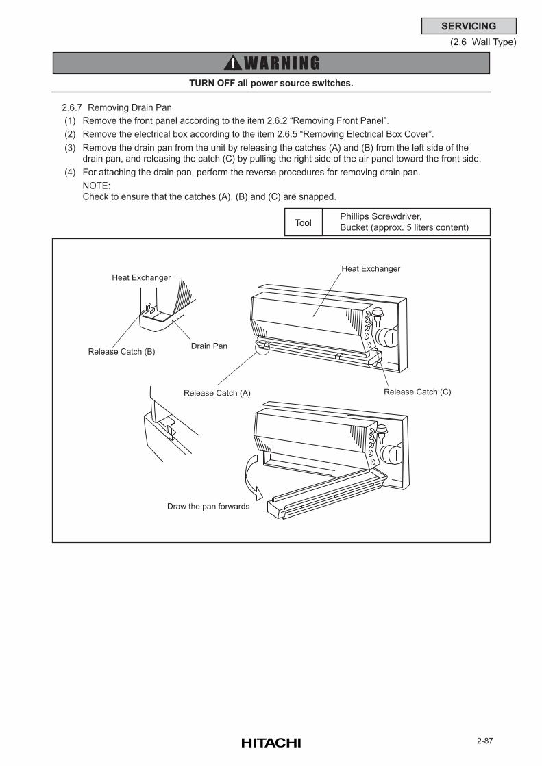
2-87
SERVICING
(2.6 Wall Type)
TURN OFF all power source switches.
Phillips Screwdriver,
Bucket (approx. 5 liters content)Tool
2.6.7 Removing Drain Pan
(1) Remove the front panel according to the item 2.6.2 “Removing Front Panel”.
(2) Remove the electrical box according to the item 2.6.5 “Removing Electrical Box Cover”.
(3) Remove the drain pan from the unit by releasing the catches (A) and (B) from the left side of the
drain pan, and releasing the catch (C) by pulling the right side of the air panel toward the front side.
(4) For attaching the drain pan, perform the reverse procedures for removing drain pan.
NOTE:
Check to ensure that the catches (A), (B) and (C) are snapped.
Heat Exchanger
Release Catch (A)
Drain Pan
Draw the pan forwards
Release Catch (C)
Heat Exchanger
Release Catch (B)
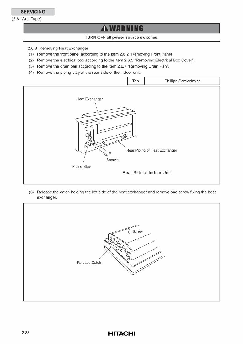
2-88
SERVICING
(2.6 Wall Type)
Phillips ScrewdriverTool
TURN OFF all power source switches.
(5) Release the catch holding the left side of the heat exchanger and remove one screw fixing the heat
exchanger.
2.6.8 Removing Heat Exchanger
(1) Remove the front panel according to the item 2.6.2 “Removing Front Panel”.
(2) Remove the electrical box according to the item 2.6.5 “Removing Electrical Box Cover”.
(3) Remove the drain pan according to the item 2.6.7 “Removing Drain Pan”.
(4) Remove the piping stay at the rear side of the indoor unit.
Heat Exchanger
Piping Stay
Rear Side of Indoor Unit
Screws
Rear Piping of Heat Exchanger
Screw
Release Catch
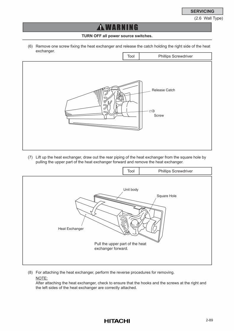
2-89
SERVICING
(2.6 Wall Type)
Phillips ScrewdriverTool
TURN OFF all power source switches.
(6) Remove one screw fixing the heat exchanger and release the catch holding the right side of the heat
exchanger.
Phillips ScrewdriverTool
(7) Lift up the heat exchanger, draw out the rear piping of the heat exchanger from the square hole by
pulling the upper part of the heat exchanger forward and remove the heat exchanger.
(8) For attaching the heat exchanger, perform the reverse procedures for removing.
NOTE:
After attaching the heat exchanger, check to ensure that the hooks and the screws at the right and
the left sides of the heat exchanger are correctly attached.
Release Catch
Screw
Unit body
Square Hole
Pull the upper part of the heat exchanger forward.
Heat Exchanger
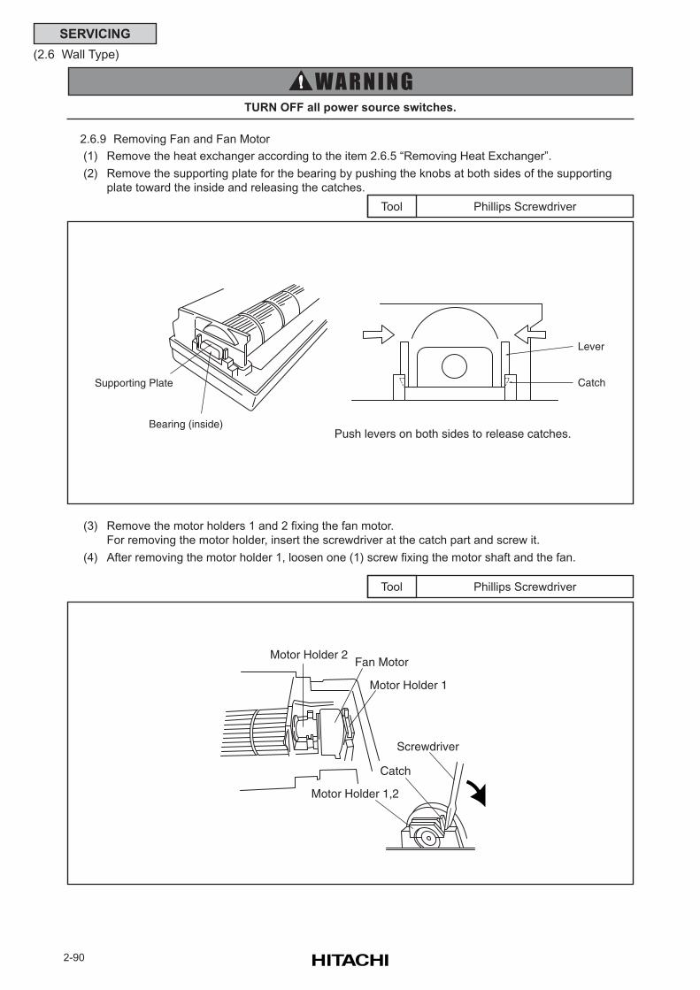
2-90
SERVICING
(2.6 Wall Type)
Phillips ScrewdriverTool
TURN OFF all power source switches.
2.6.9 Removing Fan and Fan Motor
(1) Remove the heat exchanger according to the item 2.6.5 “Removing Heat Exchanger”.
(2) Remove the supporting plate for the bearing by pushing the knobs at both sides of the supporting
plate toward the inside and releasing the catches.
Phillips ScrewdriverTool
(3) Remove the motor holders 1 and 2 fixing the fan motor.
For removing the motor holder, insert the screwdriver at the catch part and screw it.
(4) After removing the motor holder 1, loosen one (1) screw fixing the motor shaft and the fan.
Push levers on both sides to release catches.Bearing (inside)
Supporting Plate
Lever
Catch
Motor Holder 2Fan Motor
Motor Holder 1
Screwdriver
Catch
Motor Holder 1,2
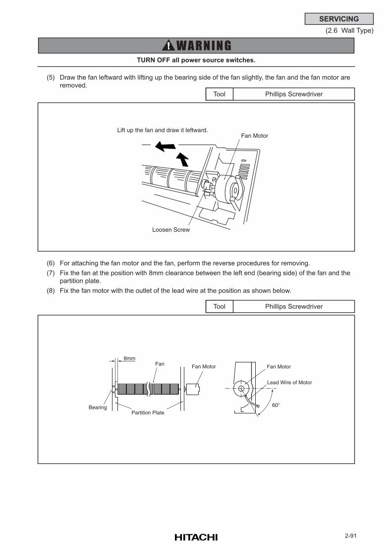
2-91
SERVICING
(2.6 Wall Type)
Phillips ScrewdriverTool
TURN OFF all power source switches.
(5) Draw the fan leftward with lifting up the bearing side of the fan slightly, the fan and the fan motor are
removed.
Phillips ScrewdriverTool
(6) For attaching the fan motor and the fan, perform the reverse procedures for removing.
(7) Fix the fan at the position with 8mm clearance between the left end (bearing side) of the fan and the
partition plate.
(8) Fix the fan motor with the outlet of the lead wire at the position as shown below.
Loosen Screw
Fan MotorLift up the fan and draw it leftward.
60o
Lead Wire of Motor
Fan Motor
Partition PlateBearing
Fan8mm
Fan Motor
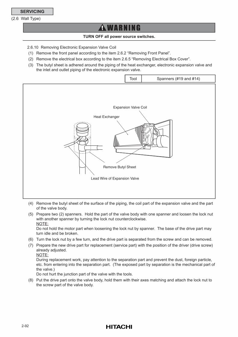
2-92
SERVICING
(2.6 Wall Type)
2.6.10 Removing Electronic Expansion Valve Coil
(1) Remove the front panel according to the item 2.6.2 “Removing Front Panel”.
(2) Remove the electrical box according to the item 2.6.5 “Removing Electrical Box Cover”.
(3) The butyl sheet is adhered around the piping of the heat exchanger, electronic expansion valve and
the inlet and outlet piping of the electronic expansion valve.
TURN OFF all power source switches.
Spanners (#19 and #14)Tool
(4) Remove the butyl sheet of the surface of the piping, the coil part of the expansion valve and the part
of the valve body.
(5) Prepare two (2) spanners. Hold the part of the valve body with one spanner and loosen the lock nut
with another spanner by turning the lock nut counterclockwise.
NOTE:
Do not hold the motor part when loosening the lock nut by spanner. The base of the drive part may
turn idle and be broken.
(6) Turn the lock nut by a few turn, and the drive part is separated from the screw and can be removed.
(7) Prepare the new drive part for replacement (service part) with the position of the driver (drive screw)
already adjusted.
NOTE:
During replacement work, pay attention to the separation part and prevent the dust, foreign particle,
etc. from entering into the separation part. (The exposed part by separation is the mechanical part of
the valve.)
Do not hurt the junction part of the valve with the tools.
(8) Put the drive part onto the valve body, hold them with their axes matching and attach the lock nut to
the screw part of the valve body.
Lead Wire of Expansion Valve
Remove Butyl Sheet
Heat Exchanger
Expansion Valve Coil
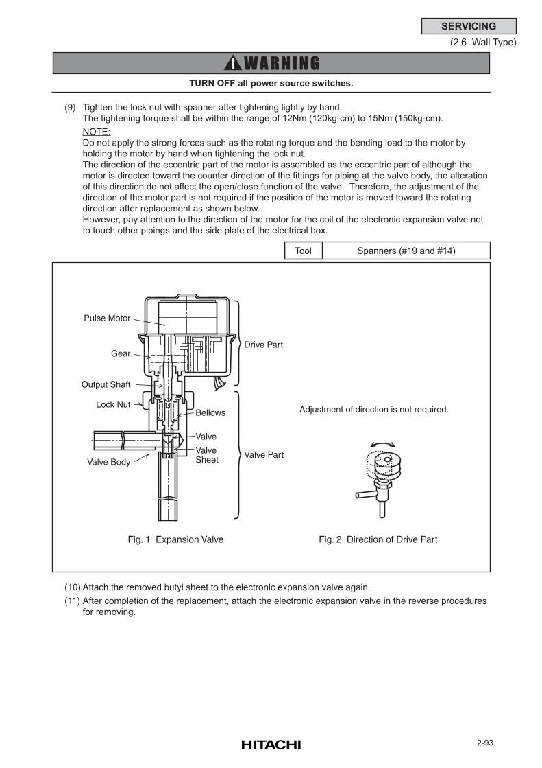
2-93
SERVICING
(2.6 Wall Type)
TURN OFF all power source switches.
Spanners (#19 and #14)Tool
(9) Tighten the lock nut with spanner after tightening lightly by hand.
The tightening torque shall be within the range of 12Nm (120kg-cm) to 15Nm (150kg-cm).
NOTE:
Do not apply the strong forces such as the rotating torque and the bending load to the motor by
holding the motor by hand when tightening the lock nut.
The direction of the eccentric part of the motor is assembled as the eccentric part of although the
motor is directed toward the counter direction of the fittings for piping at the valve body, the alteration
of this direction do not affect the open/close function of the valve. Therefore, the adjustment of the
direction of the motor part is not required if the position of the motor is moved toward the rotating
direction after replacement as shown below.
However, pay attention to the direction of the motor for the coil of the electronic expansion valve not
to touch other pipings and the side plate of the electrical box.
(10) Attach the removed butyl sheet to the electronic expansion valve again.
(11) After completion of the replacement, attach the electronic expansion valve in the reverse procedures
for removing.
Pulse Motor
Gear
Output Shaft
Lock Nut
Valve BodyValve Sheet
Valve
Valve Part
Drive Part
Bellows
Fig. 1 Expansion Valve Fig. 2 Direction of Drive Part
Adjustment of direction is not required.
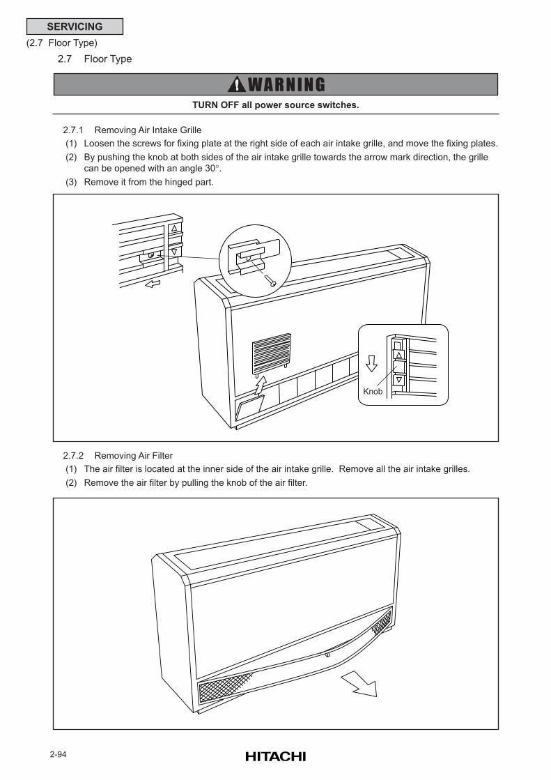
2-94
SERVICING
(2.7 Floor Type)
2.7.1 Removing Air Intake Grille
(1) Loosen the screws for fixing plate at the right side of each air intake grille, and move the fixing plates.
(2) By pushing the knob at both sides of the air intake grille towards the arrow mark direction, the grille
can be opened with an angle 30°.(3) Remove it from the hinged part.
2.7.2 Removing Air Filter
(1) The air filter is located at the inner side of the air intake grille. Remove all the air intake grilles.
(2) Remove the air filter by pulling the knob of the air filter.
2.7 Floor Type
TURN OFF all power source switches.
Knob
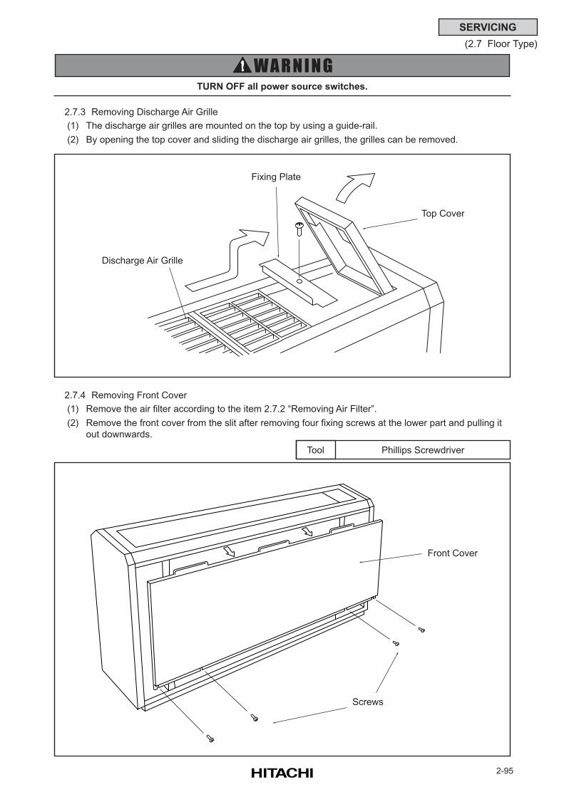
2-95
SERVICING
(2.7 Floor Type)
TURN OFF all power source switches.
2.7.3 Removing Discharge Air Grille
(1) The discharge air grilles are mounted on the top by using a guide-rail.
(2) By opening the top cover and sliding the discharge air grilles, the grilles can be removed.
Phillips ScrewdriverTool
2.7.4 Removing Front Cover
(1) Remove the air filter according to the item 2.7.2 “Removing Air Filter”.
(2) Remove the front cover from the slit after removing four fixing screws at the lower part and pulling it
out downwards.
Top Cover
Fixing Plate
Discharge Air Grille
Front Cover
Screws
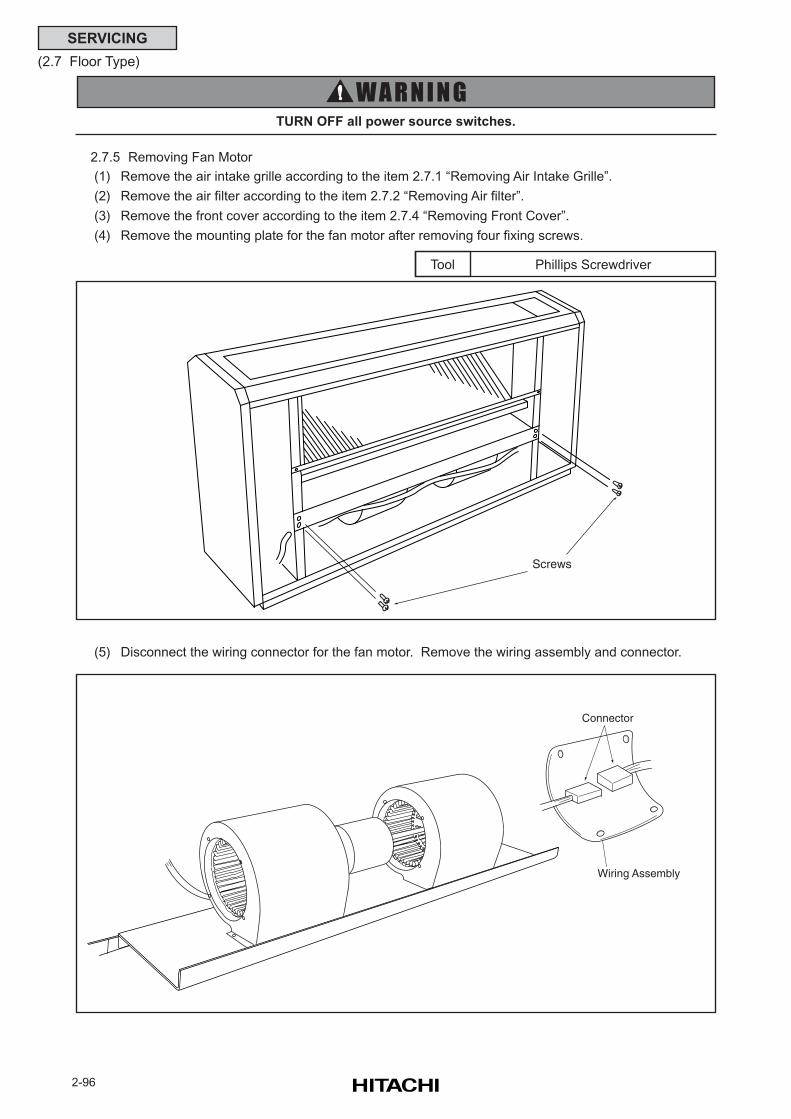
2-96
SERVICING
(2.7 Floor Type)
TURN OFF all power source switches.
2.7.5 Removing Fan Motor
(1) Remove the air intake grille according to the item 2.7.1 “Removing Air Intake Grille”.
(2) Remove the air filter according to the item 2.7.2 “Removing Air filter”.
(3) Remove the front cover according to the item 2.7.4 “Removing Front Cover”.
(4) Remove the mounting plate for the fan motor after removing four fixing screws.
(5) Disconnect the wiring connector for the fan motor. Remove the wiring assembly and connector.
Phillips ScrewdriverTool
Screws
Connector
Wiring Assembly
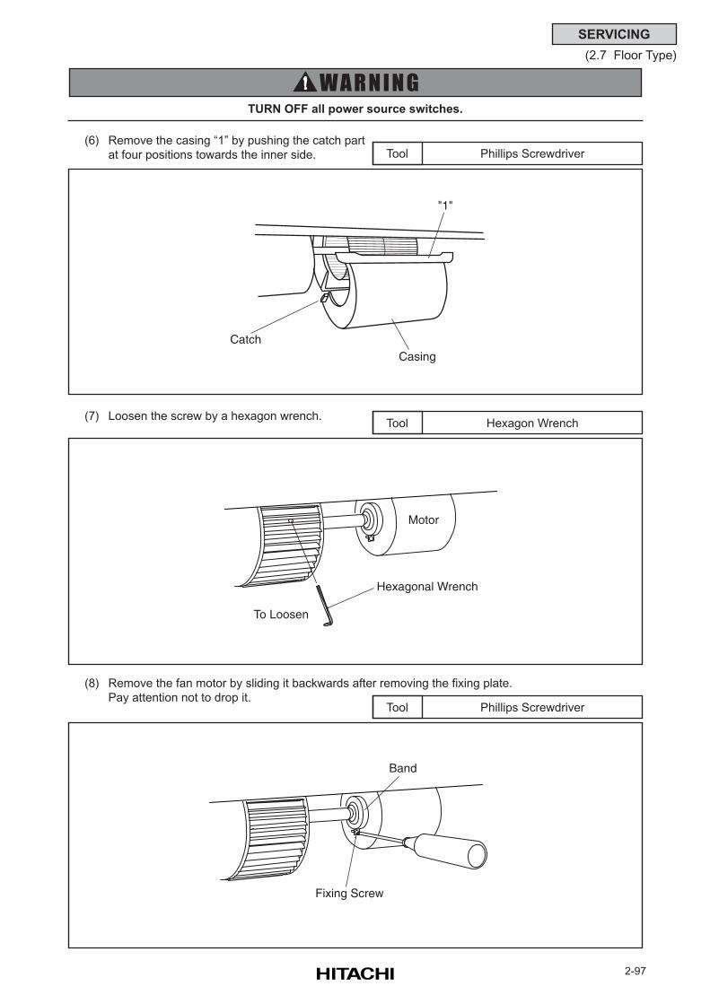
2-97
SERVICING
(2.7 Floor Type)
Phillips ScrewdriverTool
TURN OFF all power source switches.
(6) Remove the casing “1” by pushing the catch part
at four positions towards the inner side.
Hexagon WrenchTool(7) Loosen the screw by a hexagon wrench.
Phillips ScrewdriverTool
(8) Remove the fan motor by sliding it backwards after removing the fixing plate.
Pay attention not to drop it.
CatchCasing
"1"
Hexagonal Wrench
To Loosen
Motor
Band
Fixing Screw
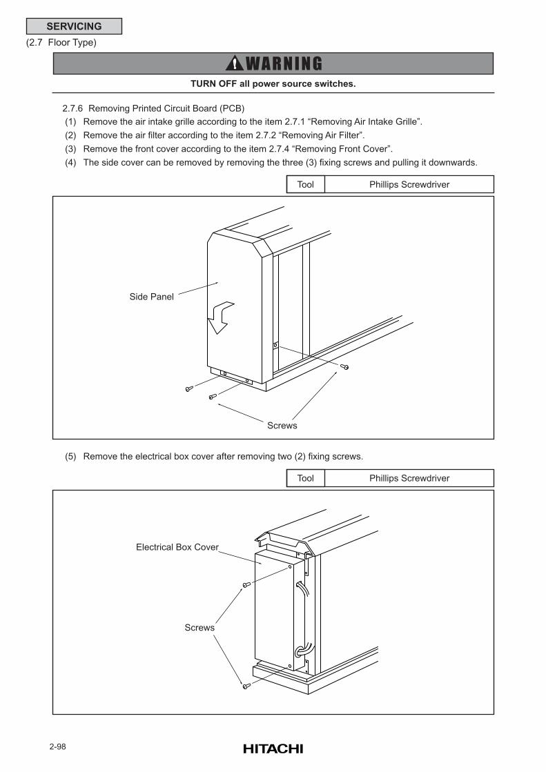
2-98
SERVICING
(2.7 Floor Type)
Phillips ScrewdriverTool
TURN OFF all power source switches.
Phillips ScrewdriverTool
(5) Remove the electrical box cover after removing two (2) fixing screws.
2.7.6 Removing Printed Circuit Board (PCB)
(1) Remove the air intake grille according to the item 2.7.1 “Removing Air Intake Grille”.
(2) Remove the air filter according to the item 2.7.2 “Removing Air Filter”.
(3) Remove the front cover according to the item 2.7.4 “Removing Front Cover”.
(4) The side cover can be removed by removing the three (3) fixing screws and pulling it downwards.
Side Panel
Screws
Electrical Box Cover
Screws
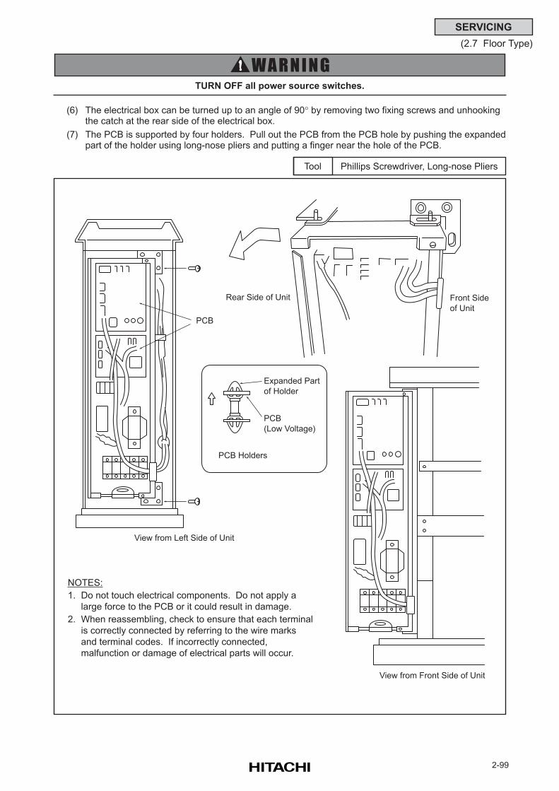
2-99
SERVICING
(2.7 Floor Type)
(6) The electrical box can be turned up to an angle of 90° by removing two fixing screws and unhookingthe catch at the rear side of the electrical box.
(7) The PCB is supported by four holders. Pull out the PCB from the PCB hole by pushing the expandedpart of the holder using long-nose pliers and putting a finger near the hole of the PCB.
TURN OFF all power source switches.
Phillips Screwdriver, Long-nose PliersTool
NOTES:
1. Do not touch electrical components. Do not apply a
large force to the PCB or it could result in damage.
2. When reassembling, check to ensure that each terminal
is correctly connected by referring to the wire marks
and terminal codes. If incorrectly connected,
malfunction or damage of electrical parts will occur.
View from Left Side of Unit
Rear Side of Unit
PCB
View from Front Side of Unit
Front Side
of Unit
Expanded Part
of Holder
PCB
(Low Voltage)
PCB Holders
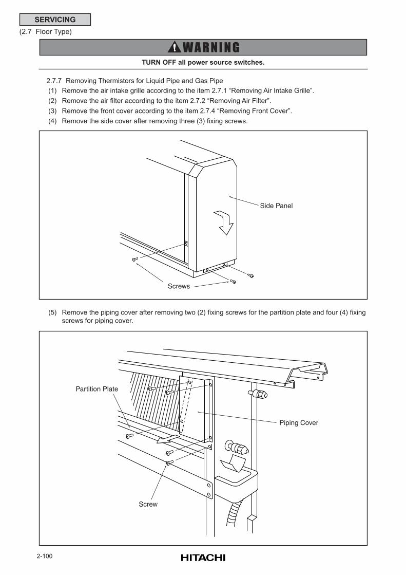
2-100
SERVICING
(2.7 Floor Type)
TURN OFF all power source switches.
2.7.7 Removing Thermistors for Liquid Pipe and Gas Pipe
(1) Remove the air intake grille according to the item 2.7.1 “Removing Air Intake Grille”.
(2) Remove the air filter according to the item 2.7.2 “Removing Air Filter”.
(3) Remove the front cover according to the item 2.7.4 “Removing Front Cover”.
(4) Remove the side cover after removing three (3) fixing screws.
(5) Remove the piping cover after removing two (2) fixing screws for the partition plate and four (4) fixing
screws for piping cover.
Partition Plate
Piping Cover
Screw
Side Panel
Screws
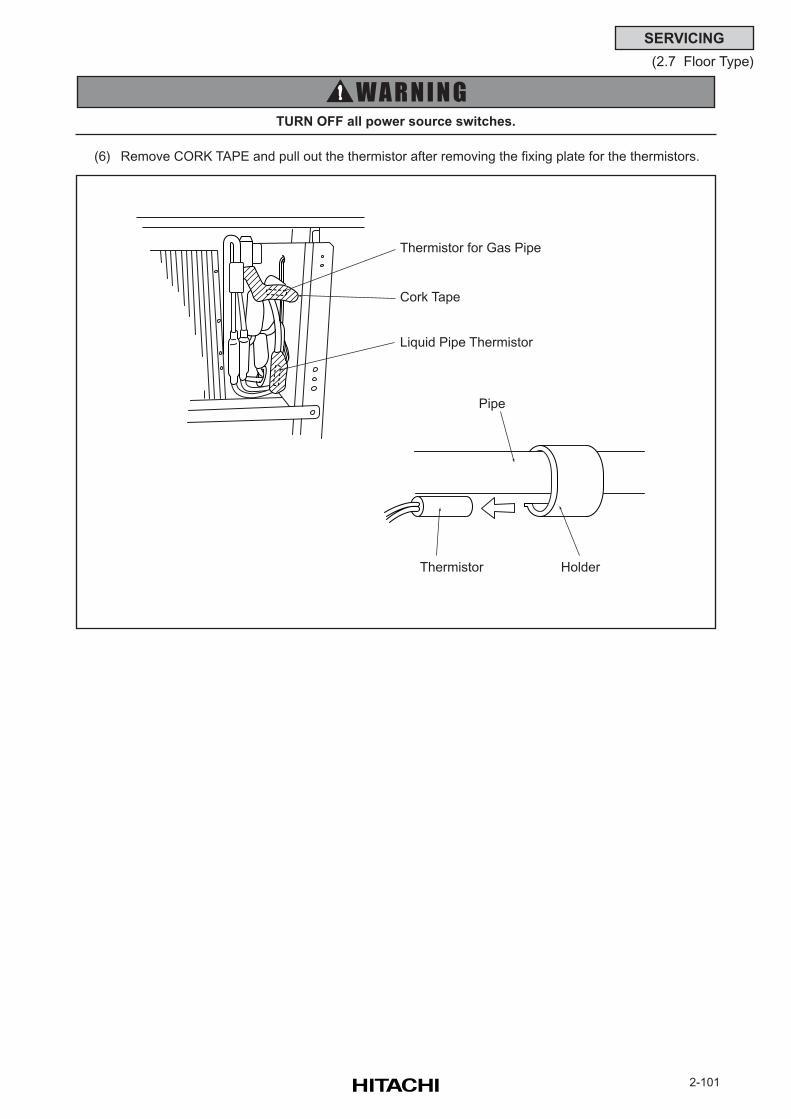
2-101
SERVICING
(2.7 Floor Type)
TURN OFF all power source switches.
(6) Remove CORK TAPE and pull out the thermistor after removing the fixing plate for the thermistors.
Thermistor for Gas Pipe
Cork Tape
Liquid Pipe Thermistor
Pipe
HolderThermistor
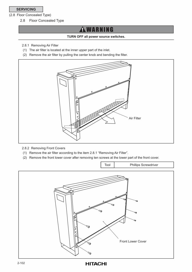
2-102
SERVICING
(2.8 Floor Concealed Type)
Phillips ScrewdriverTool
2.8 Floor Concealed Type
2.8.1 Removing Air Filter
(1) The air filter is located at the inner upper part of the inlet.
(2) Remove the air filter by pulling the center knob and bending the filter.
TURN OFF all power source switches.
2.8.2 Removing Front Covers
(1) Remove the air filter according to the item 2.8.1 “Removing Air Filter”.
(2) Remove the front lower cover after removing ten screws at the lower part of the front cover.
Air Filter
Front Lower Cover
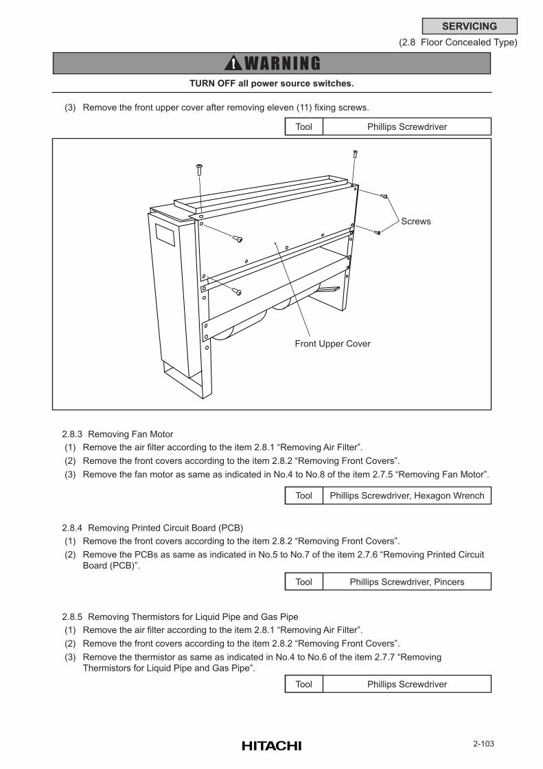
2-103
SERVICING
(2.8 Floor Concealed Type)
Phillips ScrewdriverTool
TURN OFF all power source switches.
(3) Remove the front upper cover after removing eleven (11) fixing screws.
Phillips Screwdriver, Hexagon WrenchTool
2.8.3 Removing Fan Motor
(1) Remove the air filter according to the item 2.8.1 “Removing Air Filter”.
(2) Remove the front covers according to the item 2.8.2 “Removing Front Covers”.
(3) Remove the fan motor as same as indicated in No.4 to No.8 of the item 2.7.5 “Removing Fan Motor”.
Phillips Screwdriver, PincersTool
2.8.4 Removing Printed Circuit Board (PCB)
(1) Remove the front covers according to the item 2.8.2 “Removing Front Covers”.
(2) Remove the PCBs as same as indicated in No.5 to No.7 of the item 2.7.6 “Removing Printed Circuit
Board (PCB)”.
Phillips ScrewdriverTool
2.8.5 Removing Thermistors for Liquid Pipe and Gas Pipe
(1) Remove the air filter according to the item 2.8.1 “Removing Air Filter”.
(2) Remove the front covers according to the item 2.8.2 “Removing Front Covers”.
(3) Remove the thermistor as same as indicated in No.4 to No.6 of the item 2.7.7 “Removing
Thermistors for Liquid Pipe and Gas Pipe”.
Front Upper Cover
Screws
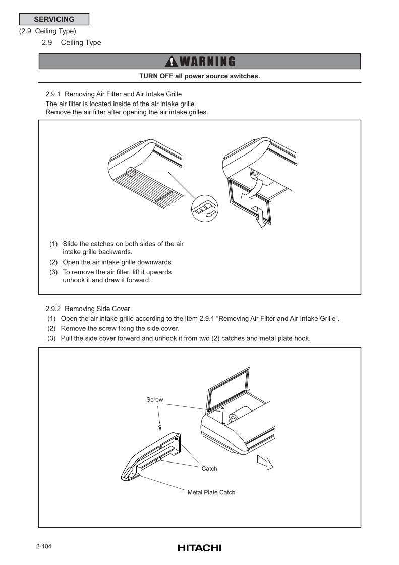
2-104
SERVICING
(2.9 Ceiling Type)
2.9 Ceiling Type
2.9.1 Removing Air Filter and Air Intake Grille
The air filter is located inside of the air intake grille.
Remove the air filter after opening the air intake grilles.
TURN OFF all power source switches.
2.9.2 Removing Side Cover
(1) Open the air intake grille according to the item 2.9.1 “Removing Air Filter and Air Intake Grille”.
(2) Remove the screw fixing the side cover.
(3) Pull the side cover forward and unhook it from two (2) catches and metal plate hook.
(1) Slide the catches on both sides of the air
intake grille backwards.
(2) Open the air intake grille downwards.
(3) To remove the air filter, lift it upwards
unhook it and draw it forward.
Screw
Catch
Metal Plate Catch
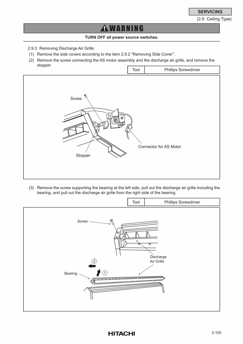
2-105
SERVICING
(2.9 Ceiling Type)
Phillips ScrewdriverTool
TURN OFF all power source switches.
Phillips ScrewdriverTool
(3) Remove the screw supporting the bearing at the left side, pull out the discharge air grille including the
bearing, and pull out the discharge air grille from the right side of the bearing.
2.9.3 Removing Discharge Air Grille
(1) Remove the side covers according to the item 2.9.2 “Removing Side Cover”.
(2) Remove the screw connecting the AS motor assembly and the discharge air grille, and remove the
stopper.
Screw
Stopper
Connector for AS Motor
Discharge
Air Grille
Screw
Bearing
2
1
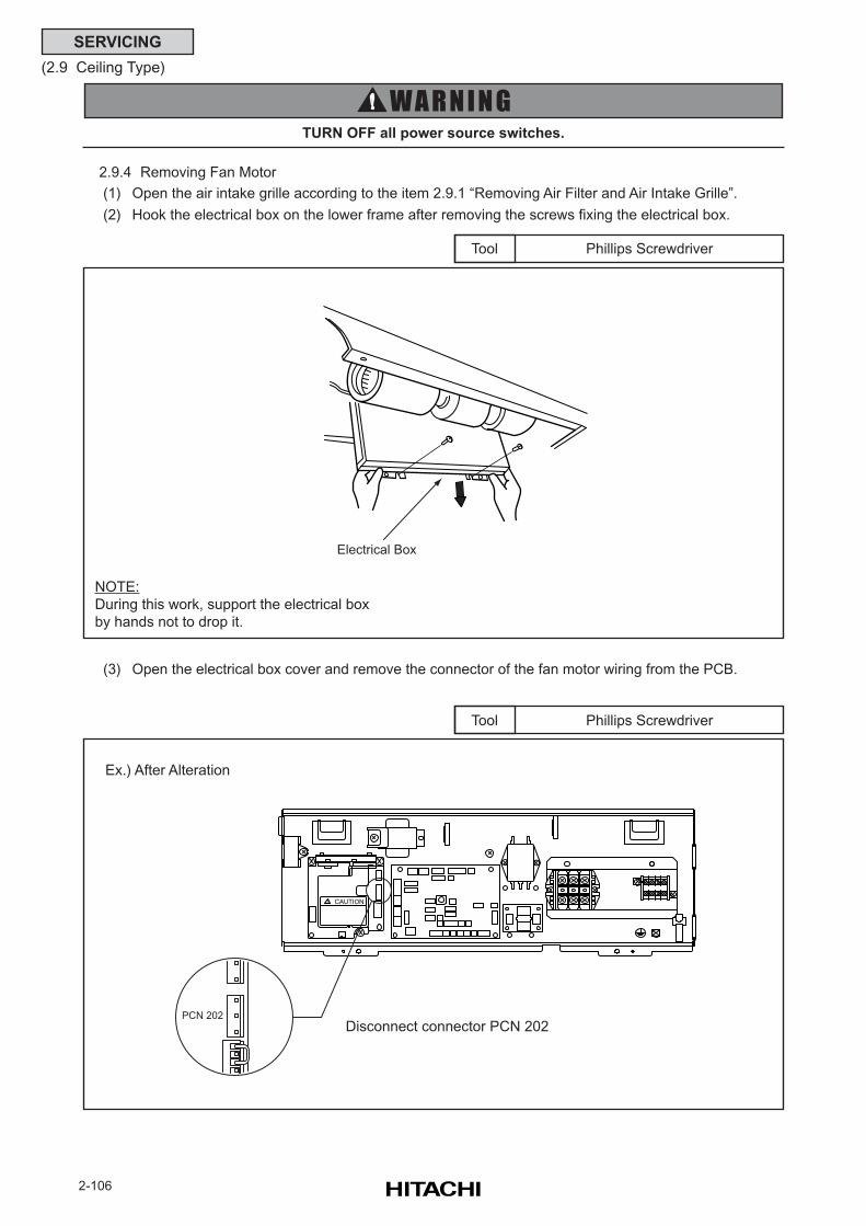
2-106
SERVICING
(2.9 Ceiling Type)
Phillips ScrewdriverTool
TURN OFF all power source switches.
Phillips ScrewdriverTool
(3) Open the electrical box cover and remove the connector of the fan motor wiring from the PCB.
2.9.4 Removing Fan Motor
(1) Open the air intake grille according to the item 2.9.1 “Removing Air Filter and Air Intake Grille”.
(2) Hook the electrical box on the lower frame after removing the screws fixing the electrical box.
NOTE:
During this work, support the electrical box
by hands not to drop it.
Electrical Box
CAUTION!
PCN 202
Disconnect connector PCN 202
Ex.) After Alteration
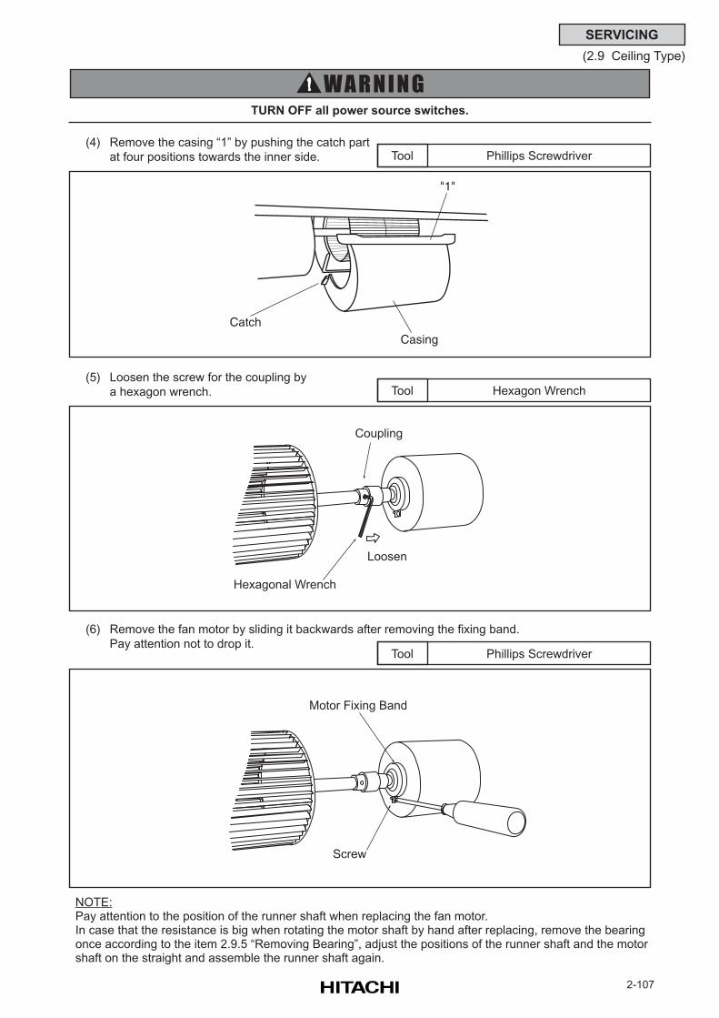
2-107
SERVICING
(2.9 Ceiling Type)
Phillips ScrewdriverTool
TURN OFF all power source switches.
(4) Remove the casing “1” by pushing the catch part
at four positions towards the inner side.
(5) Loosen the screw for the coupling by
a hexagon wrench.
Phillips ScrewdriverTool
(6) Remove the fan motor by sliding it backwards after removing the fixing band.
Pay attention not to drop it.
NOTE:Pay attention to the position of the runner shaft when replacing the fan motor.In case that the resistance is big when rotating the motor shaft by hand after replacing, remove the bearingonce according to the item 2.9.5 “Removing Bearing”, adjust the positions of the runner shaft and the motorshaft on the straight and assemble the runner shaft again.
Hexagon WrenchTool
CatchCasing
"1"
Coupling
Hexagonal Wrench
Loosen
Motor Fixing Band
Screw
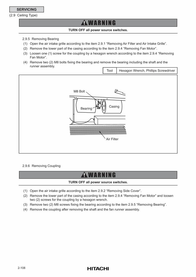
2-108
SERVICING
(2.9 Ceiling Type)
Hexagon Wrench, Phillips ScrewdriverTool
TURN OFF all power source switches.
2.9.5 Removing Bearing
(1) Open the air intake grille according to the item 2.9.1 “Removing Air Filter and Air Intake Grille”.
(2) Remove the lower part of the casing according to the item 2.9.4 “Removing Fan Motor”.
(3) Loosen one (1) screw for the coupling by a hexagon wrench according to the item 2.9.4 “Removing
Fan Motor”.
(4) Remove two (2) M8 bolts fixing the bearing and remove the bearing including the shaft and the
runner assembly.
TURN OFF all power source switches.
(1) Open the air intake grille according to the item 2.9.2 “Removing Side Cover”.
(2) Remove the lower part of the casing according to the item 2.9.4 “Removing Fan Motor” and loosen
two (2) screws for the coupling by a hexagon wrench.
(3) Remove two (2) M8 screws fixing the bearing according to the item 2.9.5 “Removing Bearing”.
(4) Remove the coupling after removing the shaft and the fan runner assembly.
2.9.6 Removing Coupling
M8 Bolt
BearingCasing
Air Filter
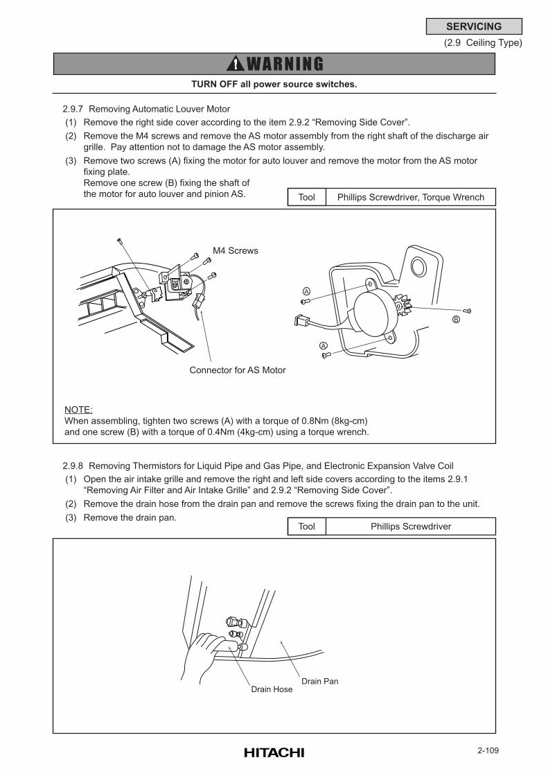
2-109
SERVICING
(2.9 Ceiling Type)
Phillips Screwdriver, Torque WrenchTool
TURN OFF all power source switches.
Phillips ScrewdriverTool
2.9.7 Removing Automatic Louver Motor
(1) Remove the right side cover according to the item 2.9.2 “Removing Side Cover”.
(2) Remove the M4 screws and remove the AS motor assembly from the right shaft of the discharge air
grille. Pay attention not to damage the AS motor assembly.
(3) Remove two screws (A) fixing the motor for auto louver and remove the motor from the AS motor
fixing plate.
Remove one screw (B) fixing the shaft of
the motor for auto louver and pinion AS.
2.9.8 Removing Thermistors for Liquid Pipe and Gas Pipe, and Electronic Expansion Valve Coil
(1) Open the air intake grille and remove the right and left side covers according to the items 2.9.1
“Removing Air Filter and Air Intake Grille” and 2.9.2 “Removing Side Cover”.
(2) Remove the drain hose from the drain pan and remove the screws fixing the drain pan to the unit.
(3) Remove the drain pan.
NOTE:
When assembling, tighten two screws (A) with a torque of 0.8Nm (8kg-cm)
and one screw (B) with a torque of 0.4Nm (4kg-cm) using a torque wrench.
Drain HoseDrain Pan
M4 Screws
A
A
B
Connector for AS Motor
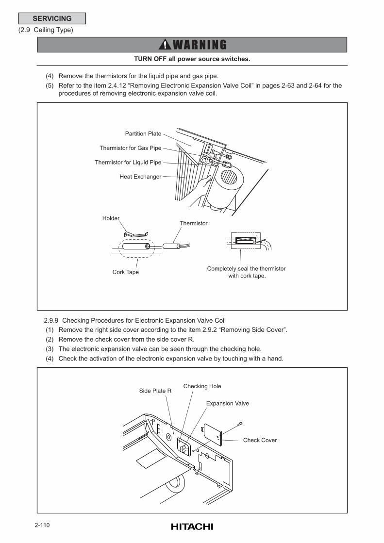
2-110
SERVICING
(2.9 Ceiling Type)
(4) Remove the thermistors for the liquid pipe and gas pipe.
(5) Refer to the item 2.4.12 “Removing Electronic Expansion Valve Coil” in pages 2-63 and 2-64 for the
procedures of removing electronic expansion valve coil.
TURN OFF all power source switches.
2.9.9 Checking Procedures for Electronic Expansion Valve Coil
(1) Remove the right side cover according to the item 2.9.2 “Removing Side Cover”.
(2) Remove the check cover from the side cover R.
(3) The electronic expansion valve can be seen through the checking hole.
(4) Check the activation of the electronic expansion valve by touching with a hand.
Partition Plate
Thermistor for Gas Pipe
Thermistor for Liquid Pipe
Heat Exchanger
ThermistorHolder
Cork TapeCompletely seal the thermistor
with cork tape.
Checking Hole
Expansion Valve
Check Cover
Side Plate R
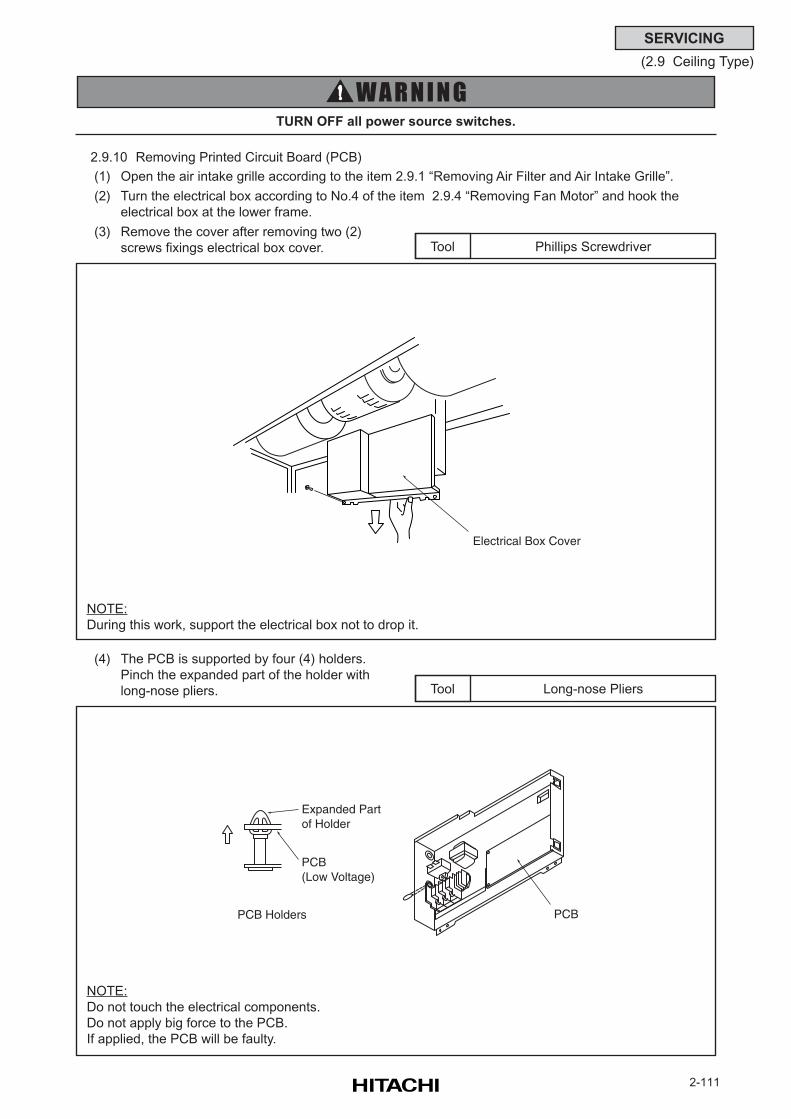
2-111
SERVICING
(2.9 Ceiling Type)
Phillips ScrewdriverTool
TURN OFF all power source switches.
Long-nose PliersTool
(4) The PCB is supported by four (4) holders.
Pinch the expanded part of the holder with
long-nose pliers.
2.9.10 Removing Printed Circuit Board (PCB)
(1) Open the air intake grille according to the item 2.9.1 “Removing Air Filter and Air Intake Grille”.
(2) Turn the electrical box according to No.4 of the item 2.9.4 “Removing Fan Motor” and hook the
electrical box at the lower frame.
(3) Remove the cover after removing two (2)
screws fixings electrical box cover.
NOTE:
During this work, support the electrical box not to drop it.
NOTE:
Do not touch the electrical components.
Do not apply big force to the PCB.
If applied, the PCB will be faulty.
Electrical Box Cover
Expanded Part of Holder
PCB (Low Voltage)
PCB Holders PCB
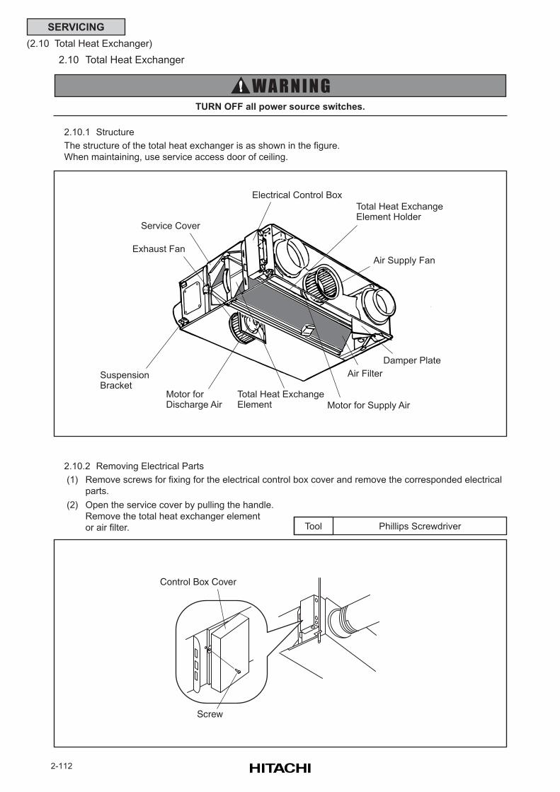
2-112
SERVICING
(2.10 Total Heat Exchanger)
Phillips ScrewdriverTool
2.10 Total Heat Exchanger
2.10.1 Structure
The structure of the total heat exchanger is as shown in the figure.
When maintaining, use service access door of ceiling.
TURN OFF all power source switches.
2.10.2 Removing Electrical Parts
(1) Remove screws for fixing for the electrical control box cover and remove the corresponded electrical
parts.
(2) Open the service cover by pulling the handle.
Remove the total heat exchanger element
or air filter.
Electrical Control Box
Air Filter
Damper Plate
Air Supply Fan
Service Cover
Exhaust Fan
Total Heat ExchangeElement
Total Heat Exchange Element Holder
Suspension Bracket
Motor for Discharge Air Motor for Supply Air
Control Box Cover
Screw
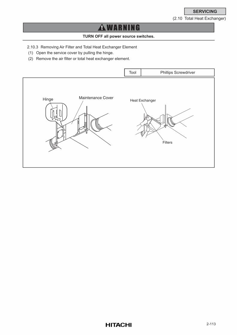
2-113
SERVICING
(2.10 Total Heat Exchanger)
Phillips ScrewdriverTool
TURN OFF all power source switches.
2.10.3 Removing Air Filter and Total Heat Exchanger Element
(1) Open the service cover by pulling the hinge.
(2) Remove the air filter or total heat exchanger element.
Filters
Heat ExchangerHinge Maintenance Cover
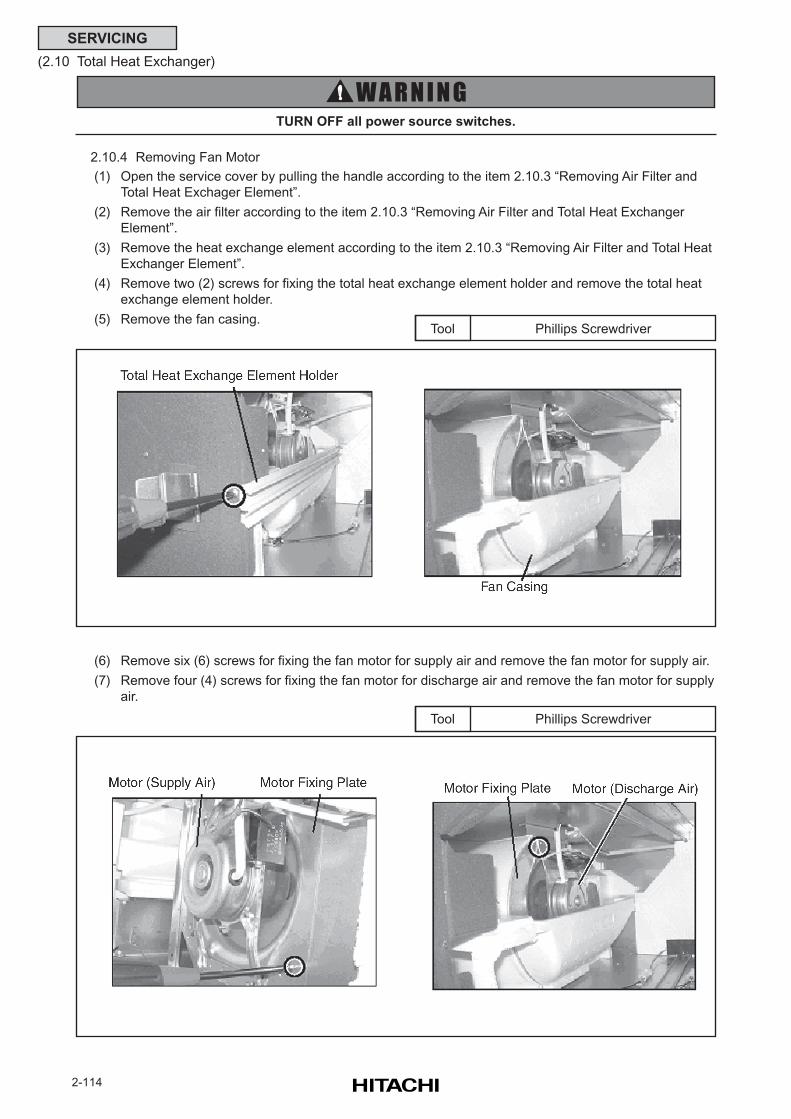
2-114
SERVICING
(2.10 Total Heat Exchanger)
Phillips ScrewdriverTool
TURN OFF all power source switches.
(6) Remove six (6) screws for fixing the fan motor for supply air and remove the fan motor for supply air.
(7) Remove four (4) screws for fixing the fan motor for discharge air and remove the fan motor for supply
air.
Phillips ScrewdriverTool
2.10.4 Removing Fan Motor
(1) Open the service cover by pulling the handle according to the item 2.10.3 “Removing Air Filter and
Total Heat Exchager Element”.
(2) Remove the air filter according to the item 2.10.3 “Removing Air Filter and Total Heat Exchanger
Element”.
(3) Remove the heat exchange element according to the item 2.10.3 “Removing Air Filter and Total Heat
Exchanger Element”.
(4) Remove two (2) screws for fixing the total heat exchange element holder and remove the total heat
exchange element holder.
(5) Remove the fan casing.
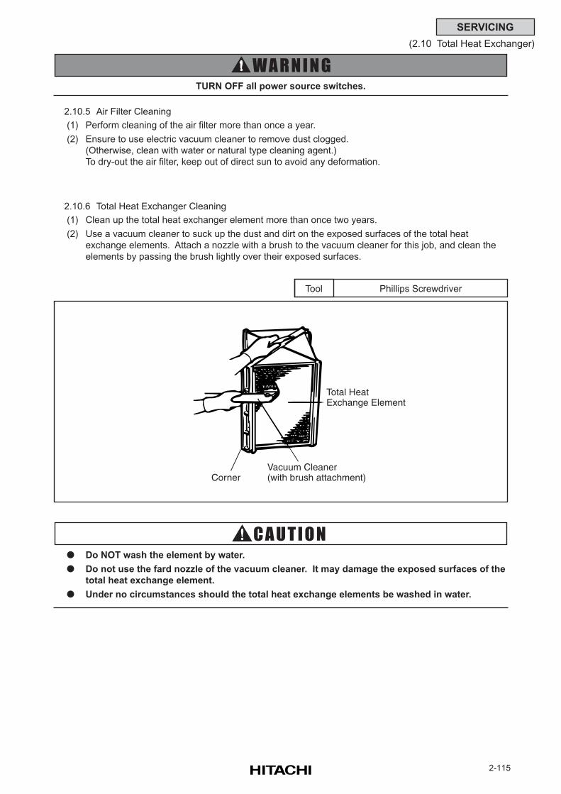
2-115
SERVICING
(2.10 Total Heat Exchanger)
Phillips ScrewdriverTool
TURN OFF all power source switches.
2.10.5 Air Filter Cleaning
(1) Perform cleaning of the air filter more than once a year.
(2) Ensure to use electric vacuum cleaner to remove dust clogged.
(Otherwise, clean with water or natural type cleaning agent.)
To dry-out the air filter, keep out of direct sun to avoid any deformation.
2.10.6 Total Heat Exchanger Cleaning
(1) Clean up the total heat exchanger element more than once two years.
(2) Use a vacuum cleaner to suck up the dust and dirt on the exposed surfaces of the total heat
exchange elements. Attach a nozzle with a brush to the vacuum cleaner for this job, and clean the
elements by passing the brush lightly over their exposed surfaces.
Do NOT wash the element by water.
Do not use the fard nozzle of the vacuum cleaner. It may damage the exposed surfaces of the
total heat exchange element.
Under no circumstances should the total heat exchange elements be washed in water.
Total HeatExchange Element
Vacuum Cleaner(with brush attachment)Corner
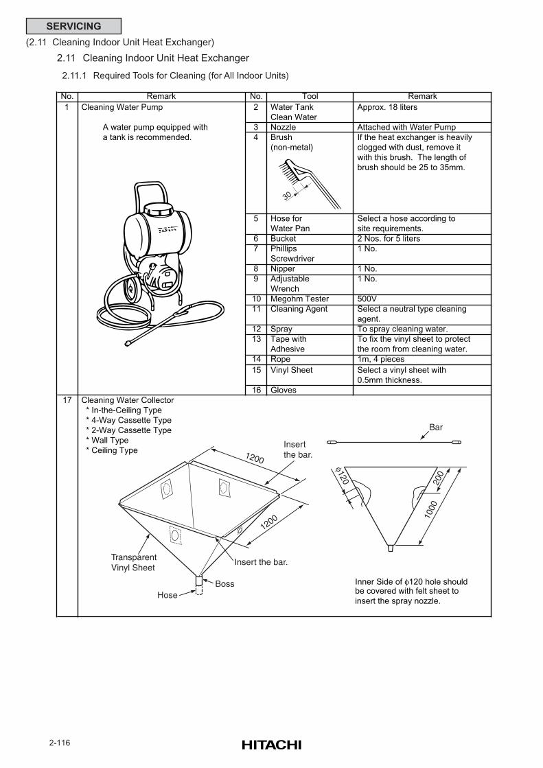
2-116
SERVICING
(2.11 Cleaning Indoor Unit Heat Exchanger)
2.11 Cleaning Indoor Unit Heat Exchanger
2.11.1 Required Tools for Cleaning (for All Indoor Units)
No. No. Tool Remark
1 Cleaning Water Pump 2 Water Tank Approx. 18 liters
Clean Water
A water pump equipped with 3 Nozzle Attached with Water Pump
a tank is recommended. 4 Brush If the heat exchanger is heavily
(non-metal) clogged with dust, remove it
with this brush. The length of
brush should be 25 to 35mm.
5 Hose for Select a hose according to
Water Pan site requirements.
6 Bucket 2 Nos. for 5 liters
7 Phillips 1 No.
Screwdriver
8 Nipper 1 No.
9 Adjustable 1 No.
Wrench
10 Megohm Tester 500V
11 Cleaning Agent Select a neutral type cleaning
agent.
12 Spray To spray cleaning water.
13 Tape with To fix the vinyl sheet to protect
Adhesive the room from cleaning water.
14 Rope 1m, 4 pieces
15 Vinyl Sheet Select a vinyl sheet with
0.5mm thickness.
16 Gloves
17 Cleaning Water Collector
* In-the-Ceiling Type
* 4-Way Cassette Type
* 2-Way Cassette Type
* Wall Type
* Ceiling Type
Inner Side of φ120 hole shouldbe covered with felt sheet to
insert the spray nozzle.
Remark
Insertthe bar.
Insert the bar.TransparentVinyl Sheet
BossHose
1200
1200
Bar
φ120 200
1000
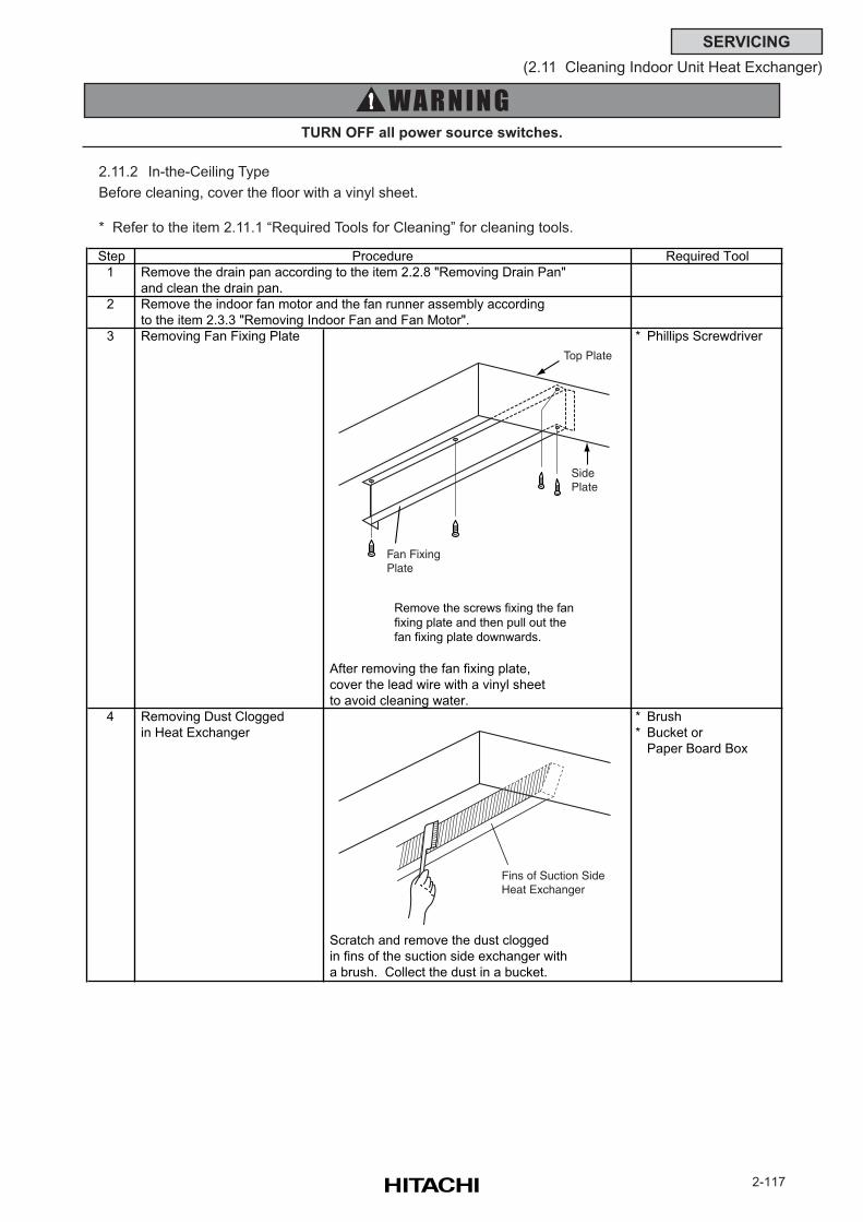
2-117
SERVICING
(2.11 Cleaning Indoor Unit Heat Exchanger)
TURN OFF all power source switches.
2.11.2 In-the-Ceiling Type
Before cleaning, cover the floor with a vinyl sheet.
* Refer to the item 2.11.1 “Required Tools for Cleaning” for cleaning tools.
Step
1 Remove the drain pan according to the item 2.2.8 "Removing Drain Pan"
and clean the drain pan.
2 Remove the indoor fan motor and the fan runner assembly according
to the item 2.3.3 "Removing Indoor Fan and Fan Motor".
3 Removing Fan Fixing Plate * Phillips Screwdriver
Remove the screws fixing the fan
fixing plate and then pull out the
fan fixing plate downwards.
After removing the fan fixing plate,
cover the lead wire with a vinyl sheet
to avoid cleaning water.
4 Removing Dust Clogged * Brush
in Heat Exchanger * Bucket or
Paper Board Box
Scratch and remove the dust clogged
in fins of the suction side exchanger with
a brush. Collect the dust in a bucket.
Procedure Required Tool
Top Plate
SidePlate
Fan FixingPlate
Fins of Suction SideHeat Exchanger
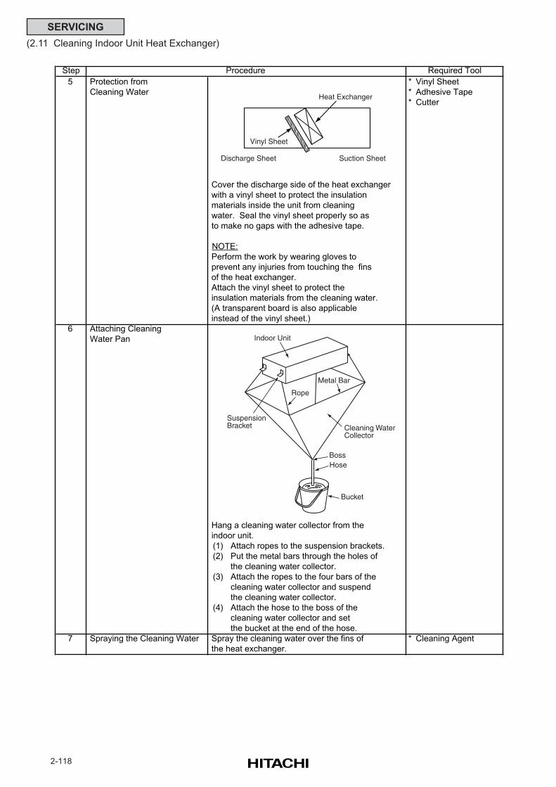
2-118
SERVICING
(2.11 Cleaning Indoor Unit Heat Exchanger)
Step
5 Protection from * Vinyl Sheet
Cleaning Water * Adhesive Tape
* Cutter
Cover the discharge side of the heat exchanger
with a vinyl sheet to protect the insulation
materials inside the unit from cleaning
water. Seal the vinyl sheet properly so as
to make no gaps with the adhesive tape.
NOTE:
Perform the work by wearing gloves to
prevent any injuries from touching the fins
of the heat exchanger.
Attach the vinyl sheet to protect the
insulation materials from the cleaning water.
(A transparent board is also applicable
instead of the vinyl sheet.)
6 Attaching Cleaning
Water Pan
Hang a cleaning water collector from the
indoor unit.
(1) Attach ropes to the suspension brackets.
(2) Put the metal bars through the holes of
the cleaning water collector.
(3) Attach the ropes to the four bars of the
cleaning water collector and suspend
the cleaning water collector.
(4) Attach the hose to the boss of the
cleaning water collector and set
the bucket at the end of the hose.
7 Spraying the Cleaning Water Spray the cleaning water over the fins of * Cleaning Agent
the heat exchanger.
Procedure Required Tool
Vinyl Sheet
Heat Exchanger
Discharge Sheet Suction Sheet
Cleaning WaterCollector
BossHose
Indoor Unit
SuspensionBracket
Rope
Metal Bar
Bucket
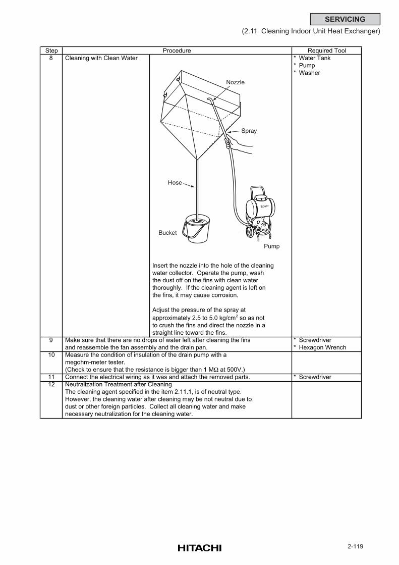
2-119
SERVICING
(2.11 Cleaning Indoor Unit Heat Exchanger)
Step
8 Cleaning with Clean Water * Water Tank
* Pump
* Washer
Insert the nozzle into the hole of the cleaning
water collector. Operate the pump, wash
the dust off on the fins with clean water
thoroughly. If the cleaning agent is left on
the fins, it may cause corrosion.
Adjust the pressure of the spray at
approximately 2.5 to 5.0 kg/cm2 so as not
to crush the fins and direct the nozzle in a
straight line toward the fins.
9 Make sure that there are no drops of water left after cleaning the fins * Screwdriver
and reassemble the fan assembly and the drain pan. * Hexagon Wrench
10 Measure the condition of insulation of the drain pump with a
megohm-meter tester.
(Check to ensure that the resistance is bigger than 1 MΩ at 500V.)
11 Connect the electrical wiring as it was and attach the removed parts. * Screwdriver
12 Neutralization Treatment after Cleaning
The cleaning agent specified in the item 2.11.1, is of neutral type.
However, the cleaning water after cleaning may be not neutral due to
dust or other foreign particles. Collect all cleaning water and make
necessary neutralization for the cleaning water.
Procedure Required Tool
Nozzle
Spray
Pump
Hose
Bucket
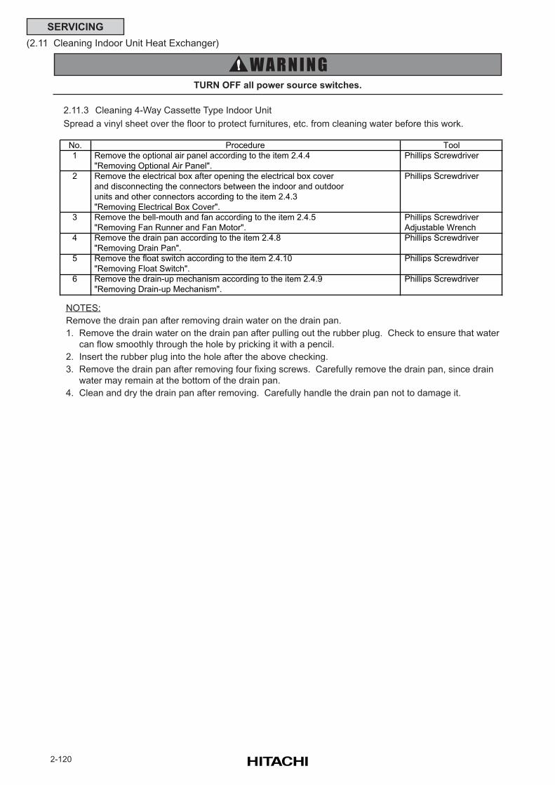
2-120
SERVICING
(2.11 Cleaning Indoor Unit Heat Exchanger)
TURN OFF all power source switches.
NOTES:
Remove the drain pan after removing drain water on the drain pan.
1. Remove the drain water on the drain pan after pulling out the rubber plug. Check to ensure that water
can flow smoothly through the hole by pricking it with a pencil.
2. Insert the rubber plug into the hole after the above checking.
3. Remove the drain pan after removing four fixing screws. Carefully remove the drain pan, since drain
water may remain at the bottom of the drain pan.
4. Clean and dry the drain pan after removing. Carefully handle the drain pan not to damage it.
2.11.3 Cleaning 4-Way Cassette Type Indoor Unit
Spread a vinyl sheet over the floor to protect furnitures, etc. from cleaning water before this work.
No. Procedure Tool
1 Remove the optional air panel according to the item 2.4.4 Phillips Screwdriver
"Removing Optional Air Panel".
2 Remove the electrical box after opening the electrical box cover Phillips Screwdriver
and disconnecting the connectors between the indoor and outdoor
units and other connectors according to the item 2.4.3
"Removing Electrical Box Cover".
3 Remove the bell-mouth and fan according to the item 2.4.5 Phillips Screwdriver
"Removing Fan Runner and Fan Motor". Adjustable Wrench
4 Remove the drain pan according to the item 2.4.8 Phillips Screwdriver
"Removing Drain Pan".
5 Remove the float switch according to the item 2.4.10 Phillips Screwdriver
"Removing Float Switch".
6 Remove the drain-up mechanism according to the item 2.4.9 Phillips Screwdriver
"Removing Drain-up Mechanism".
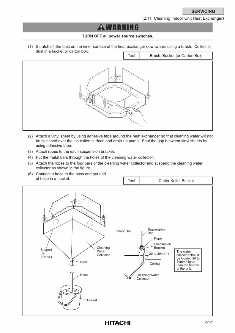
2-121
SERVICING
(2.11 Cleaning Indoor Unit Heat Exchanger)
TURN OFF all power source switches.
Brush, Bucket (or Carton Box)Tool
(1) Scratch off the dust on the inner surface of the heat exchanger downwards using a brush. Collect all
dust in a bucket or carton box.
(2) Attach a vinyl sheet by using adhesive tape around the heat exchanger so that cleaning water will not
be splashed over the insulation surface and drain-up pump. Seal the gap between vinyl sheets by
using adhesive tape.
(3) Attach ropes to the each suspension bracket.
(4) Put the metal bars through the holes of the cleaning water collector.
(5) Attach the ropes to the four bars of the cleaning water collector and suspend the cleaning water
collector as shown in the figure.
(6) Connect a hose to the boss and put end
of hose in a bucket.Cutter Knife, BucketTool
CleaningWaterCollector
Boss
SupportBar(8 Nos.)
Hose
Bucket
SuspensionBolt
Indoor Unit
Rope
SuspensionBracket
Ceiling
Cleaning WaterCollector
20 to 30mmThe water collector shouldbe located 20 to30mm higherthan the bottomof the unit.
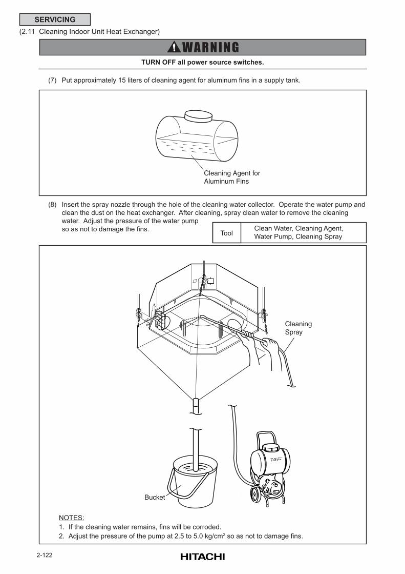
2-122
SERVICING
(2.11 Cleaning Indoor Unit Heat Exchanger)
TURN OFF all power source switches.
(7) Put approximately 15 liters of cleaning agent for aluminum fins in a supply tank.
(8) Insert the spray nozzle through the hole of the cleaning water collector. Operate the water pump and
clean the dust on the heat exchanger. After cleaning, spray clean water to remove the cleaning
water. Adjust the pressure of the water pump
so as not to damage the fins. Clean Water, Cleaning Agent,
Water Pump, Cleaning SprayTool
NOTES:
1. If the cleaning water remains, fins will be corroded.
2. Adjust the pressure of the pump at 2.5 to 5.0 kg/cm2 so as not to damage fins.
Bucket
CleaningSpray
Cleaning Agent forAluminum Fins
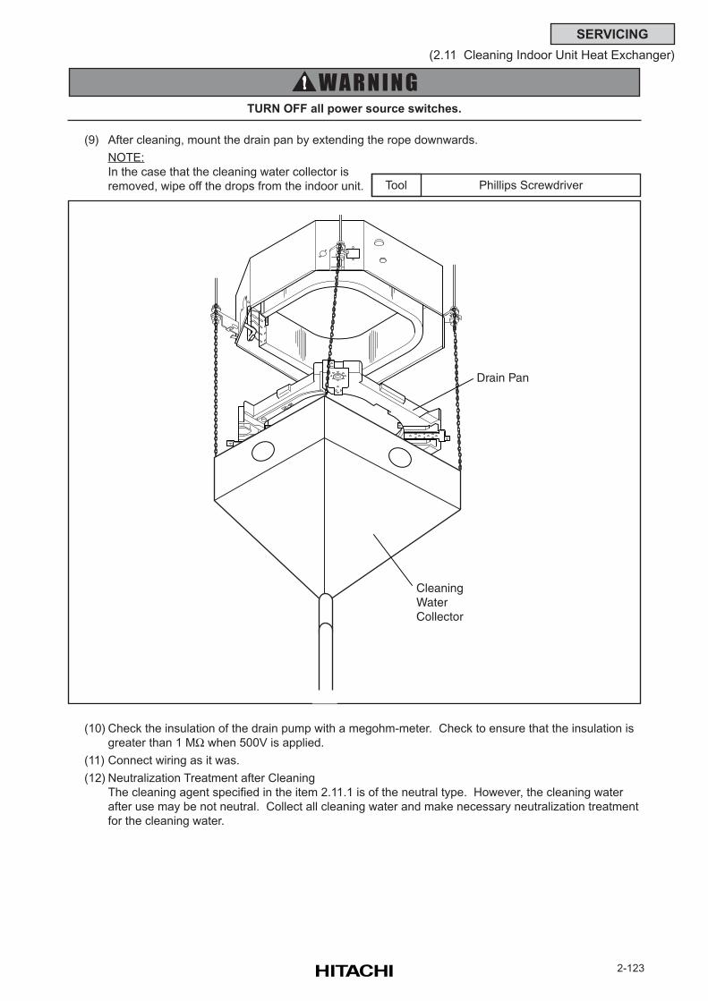
2-123
SERVICING
(2.11 Cleaning Indoor Unit Heat Exchanger)
TURN OFF all power source switches.
Phillips ScrewdriverTool
(9) After cleaning, mount the drain pan by extending the rope downwards.
NOTE:
In the case that the cleaning water collector is
removed, wipe off the drops from the indoor unit.
(10) Check the insulation of the drain pump with a megohm-meter. Check to ensure that the insulation is
greater than 1 MΩ when 500V is applied.
(11) Connect wiring as it was.
(12) Neutralization Treatment after Cleaning
The cleaning agent specified in the item 2.11.1 is of the neutral type. However, the cleaning water
after use may be not neutral. Collect all cleaning water and make necessary neutralization treatment
for the cleaning water.
Drain Pan
CleaningWaterCollector
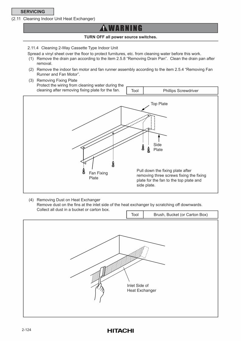
2-124
SERVICING
(2.11 Cleaning Indoor Unit Heat Exchanger)
2.11.4 Cleaning 2-Way Cassette Type Indoor Unit
Spread a vinyl sheet over the floor to protect furnitures, etc. from cleaning water before this work.
(1) Remove the drain pan according to the item 2.5.8 “Removing Drain Pan”. Clean the drain pan after
removal.
(2) Remove the indoor fan motor and fan runner assembly according to the item 2.5.4 “Removing Fan
Runner and Fan Motor”.
(3) Removing Fixing Plate
Protect the wiring from cleaning water during the
cleaning after removing fixing plate for the fan.
TURN OFF all power source switches.
(4) Removing Dust on Heat Exchanger
Remove dust on the fins at the inlet side of the heat exchanger by scratching off downwards.
Collect all dust in a bucket or carton box.
Phillips ScrewdriverTool
Brush, Bucket (or Carton Box)Tool
Pull down the fixing plate after
removing three screws fixing the fixing
plate for the fan to the top plate and
side plate.
Top Plate
SidePlate
Fan FixingPlate
Inlet Side ofHeat Exchanger
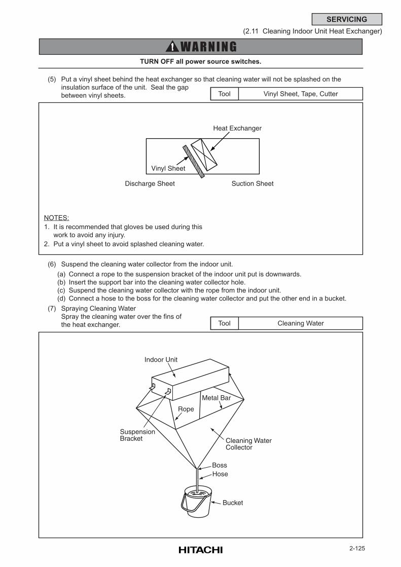
2-125
SERVICING
(2.11 Cleaning Indoor Unit Heat Exchanger)
(5) Put a vinyl sheet behind the heat exchanger so that cleaning water will not be splashed on the
insulation surface of the unit. Seal the gap
between vinyl sheets.
TURN OFF all power source switches.
(6) Suspend the cleaning water collector from the indoor unit.
(a) Connect a rope to the suspension bracket of the indoor unit put is downwards.
(b) Insert the support bar into the cleaning water collector hole.
(c) Suspend the cleaning water collector with the rope from the indoor unit.
(d) Connect a hose to the boss for the cleaning water collector and put the other end in a bucket.
(7) Spraying Cleaning Water
Spray the cleaning water over the fins of
the heat exchanger.
Vinyl Sheet, Tape, CutterTool
Cleaning WaterTool
NOTES:
1. It is recommended that gloves be used during this
work to avoid any injury.
2. Put a vinyl sheet to avoid splashed cleaning water.
Vinyl Sheet
Heat Exchanger
Discharge Sheet Suction Sheet
Cleaning WaterCollector
BossHose
Indoor Unit
SuspensionBracket
Rope
Metal Bar
Bucket
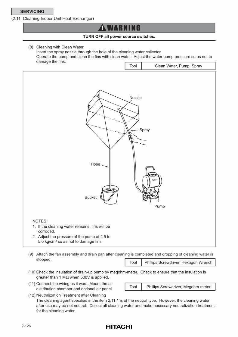
2-126
SERVICING
(2.11 Cleaning Indoor Unit Heat Exchanger)
Clean Water, Pump, SprayTool
TURN OFF all power source switches.
(9) Attach the fan assembly and drain pan after cleaning is completed and dropping of cleaning water is
stopped.
(10) Check the insulation of drain-up pump by megohm-meter. Check to ensure that the insulation is
greater than 1 MΩ when 500V is applied.
(11) Connect the wiring as it was. Mount the air
distribution chamber and optional air panel.
(12) Neutralization Treatment after Cleaning
The cleaning agent specified in the item 2.11.1 is of the neutral type. However, the cleaning water
after use may be not neutral. Collect all cleaning water and make necessary neutralization treatment
for the cleaning water.
(8) Cleaning with Clean Water
Insert the spray nozzle through the hole of the cleaning water collector.
Operate the pump and clean the fins with clean water. Adjust the water pump pressure so as not to
damage the fins.
Phillips Screwdriver, Megohm-meterTool
Phillips Screwdriver, Hexagon WrenchTool
NOTES:
1. If the cleaning water remains, fins will be
corroded.
2. Adjust the pressure of the pump at 2.5 to
5.0 kg/cm2 so as not to damage fins.
Nozzle
Spray
Pump
Hose
Bucket
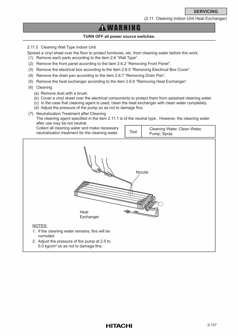
2-127
SERVICING
(2.11 Cleaning Indoor Unit Heat Exchanger)
2.11.5 Cleaning Wall Type Indoor Unit
Spread a vinyl sheet over the floor to protect furnitures, etc. from cleaning water before this work.
(1) Remove each parts according to the item 2.6 “Wall Type”.
(2) Remove the front panel according to the item 2.6.2 “Removing Front Panel”.
(3) Remove the electrical box according to the item 2.6.5 “Removing Electrical Box Cover”.
(4) Remove the drain pan according to the item 2.6.7 “Removing Drain Pan”.
(5) Remove the heat exchanger according to the item 2.6.8 “Removing Heat Exchanger”.
(6) Cleaning
(a) Remove dust with a brush.
(b) Cover a vinyl sheet over the electrical components to protect them from splashed cleaning water.
(c) In the case that cleaning agent is used, clean the heat exchanger with clean water completely.
(d) Adjust the pressure of the pump so as not to damage fins.
(7) Neutralization Treatment after Cleaning
The cleaning agent specified in the item 2.11.1 is of the neutral type. However, the cleaning water
after use may be not neutral.
Collect all cleaning water and make necessary
neutralization treatment for the cleaning water.
TURN OFF all power source switches.
Cleaning Water, Clean Water,
Pump, SprayTool
NOTES:
1. If the cleaning water remains, fins will be
corroded.
2. Adjust the pressure of the pump at 2.5 to
5.0 kg/cm2 so as not to damage fins.
Nozzle
HeatExchanger
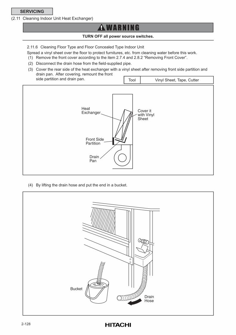
2-128
SERVICING
(2.11 Cleaning Indoor Unit Heat Exchanger)
2.11.6 Cleaning Floor Type and Floor Concealed Type Indoor Unit
Spread a vinyl sheet over the floor to protect furnitures, etc. from cleaning water before this work.
(1) Remove the front cover according to the item 2.7.4 and 2.8.2 “Removing Front Cover”.
(2) Disconnect the drain hose from the field-supplied pipe.
(3) Cover the rear side of the heat exchanger with a vinyl sheet after removing front side partition and
drain pan. After covering, remount the front
side partition and drain pan.
TURN OFF all power source switches.
(4) By lifting the drain hose and put the end in a bucket.
Vinyl Sheet, Tape, CutterTool
HeatExchanger
Front SidePartition
DrainPan
Cover itwith VinylSheet
Bucket
DrainHose
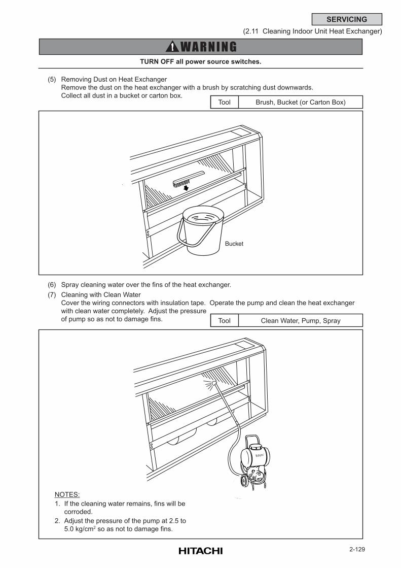
2-129
SERVICING
(2.11 Cleaning Indoor Unit Heat Exchanger)
(5) Removing Dust on Heat Exchanger
Remove the dust on the heat exchanger with a brush by scratching dust downwards.
Collect all dust in a bucket or carton box.
TURN OFF all power source switches.
Brush, Bucket (or Carton Box)Tool
(6) Spray cleaning water over the fins of the heat exchanger.
(7) Cleaning with Clean Water
Cover the wiring connectors with insulation tape. Operate the pump and clean the heat exchanger
with clean water completely. Adjust the pressure
of pump so as not to damage fins.
NOTES:
1. If the cleaning water remains, fins will be
corroded.
2. Adjust the pressure of the pump at 2.5 to
5.0 kg/cm2 so as not to damage fins.
Clean Water, Pump, SprayTool
Bucket
2-130
SERVICING
(2.11 Cleaning Indoor Unit Heat Exchanger)
TURN OFF all power source switches.
(8) After checking that no power is supplied, connect the drain pipe and remove the insulation tape for
the wiring connectors and then mount the front cover correctly.
(9) Check the insulation of the terminal board in the electrical box.
If the insulation is greater than 1MΩby a 500 Megohm-meter, it is normal.
(10) Neutralization Treatment after Cleaning
The cleaning agent specified in the item 2.11.1 is of the neutral type. However, the cleaning water
after use may be not neutral. Collect all cleaning water and make necessary neutralization treatment
for the cleaning water.
Megohm-meter, Voltage-Checker,
Phillips ScrewdriverTool
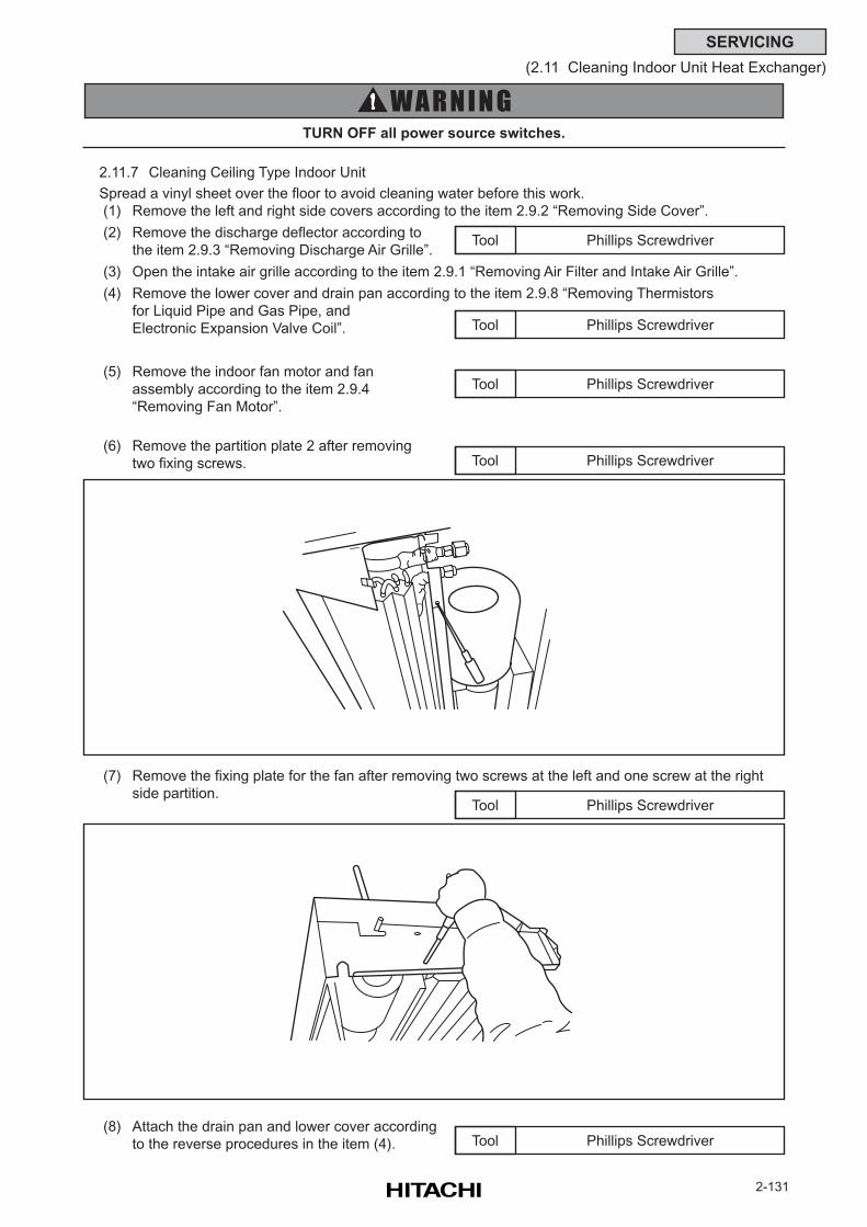
2-131
SERVICING
(2.11 Cleaning Indoor Unit Heat Exchanger)
2.11.7 Cleaning Ceiling Type Indoor Unit
Spread a vinyl sheet over the floor to avoid cleaning water before this work.
(1) Remove the left and right side covers according to the item 2.9.2 “Removing Side Cover”.
(2) Remove the discharge deflector according to
the item 2.9.3 “Removing Discharge Air Grille”.
(3) Open the intake air grille according to the item 2.9.1 “Removing Air Filter and Intake Air Grille”.
(4) Remove the lower cover and drain pan according to the item 2.9.8 “Removing Thermistors
for Liquid Pipe and Gas Pipe, and
Electronic Expansion Valve Coil”.
(5) Remove the indoor fan motor and fan
assembly according to the item 2.9.4
“Removing Fan Motor”.
(6) Remove the partition plate 2 after removing
two fixing screws.
TURN OFF all power source switches.
Phillips ScrewdriverTool
Phillips ScrewdriverTool
Phillips ScrewdriverTool
(7) Remove the fixing plate for the fan after removing two screws at the left and one screw at the right
side partition.
Phillips ScrewdriverTool
Phillips ScrewdriverTool
(8) Attach the drain pan and lower cover according
to the reverse procedures in the item (4). Phillips ScrewdriverTool
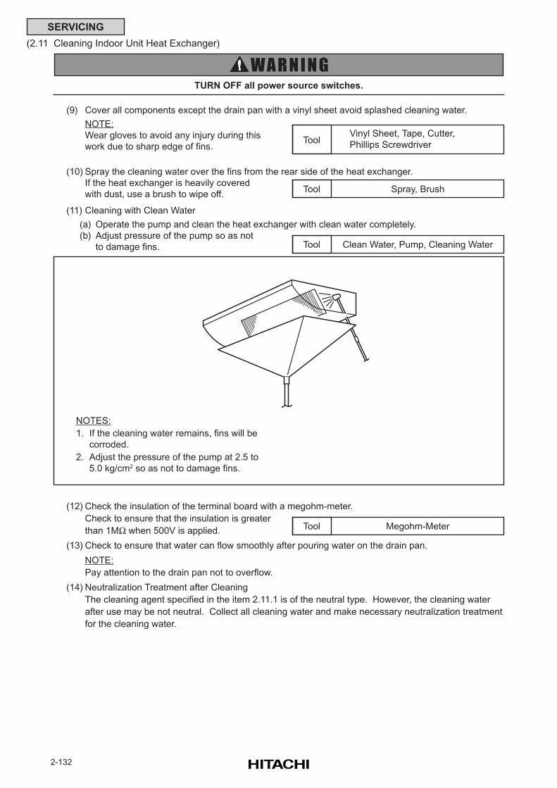
2-132
SERVICING
(2.11 Cleaning Indoor Unit Heat Exchanger)
(9) Cover all components except the drain pan with a vinyl sheet avoid splashed cleaning water.
NOTE:
Wear gloves to avoid any injury during this
work due to sharp edge of fins.
(10) Spray the cleaning water over the fins from the rear side of the heat exchanger.
If the heat exchanger is heavily covered
with dust, use a brush to wipe off.
TURN OFF all power source switches.
Megohm-MeterTool
(11) Cleaning with Clean Water
(a) Operate the pump and clean the heat exchanger with clean water completely.
(b) Adjust pressure of the pump so as not
to damage fins.
NOTES:
1. If the cleaning water remains, fins will be
corroded.
2. Adjust the pressure of the pump at 2.5 to
5.0 kg/cm2 so as not to damage fins.
Clean Water, Pump, Cleaning WaterTool
Vinyl Sheet, Tape, Cutter,
Phillips ScrewdriverTool
Spray, BrushTool
(12) Check the insulation of the terminal board with a megohm-meter.
Check to ensure that the insulation is greater
than 1MΩ when 500V is applied.
(13) Check to ensure that water can flow smoothly after pouring water on the drain pan.
NOTE:
Pay attention to the drain pan not to overflow.
(14) Neutralization Treatment after Cleaning
The cleaning agent specified in the item 2.11.1 is of the neutral type. However, the cleaning water
after use may be not neutral. Collect all cleaning water and make necessary neutralization treatment
for the cleaning water.
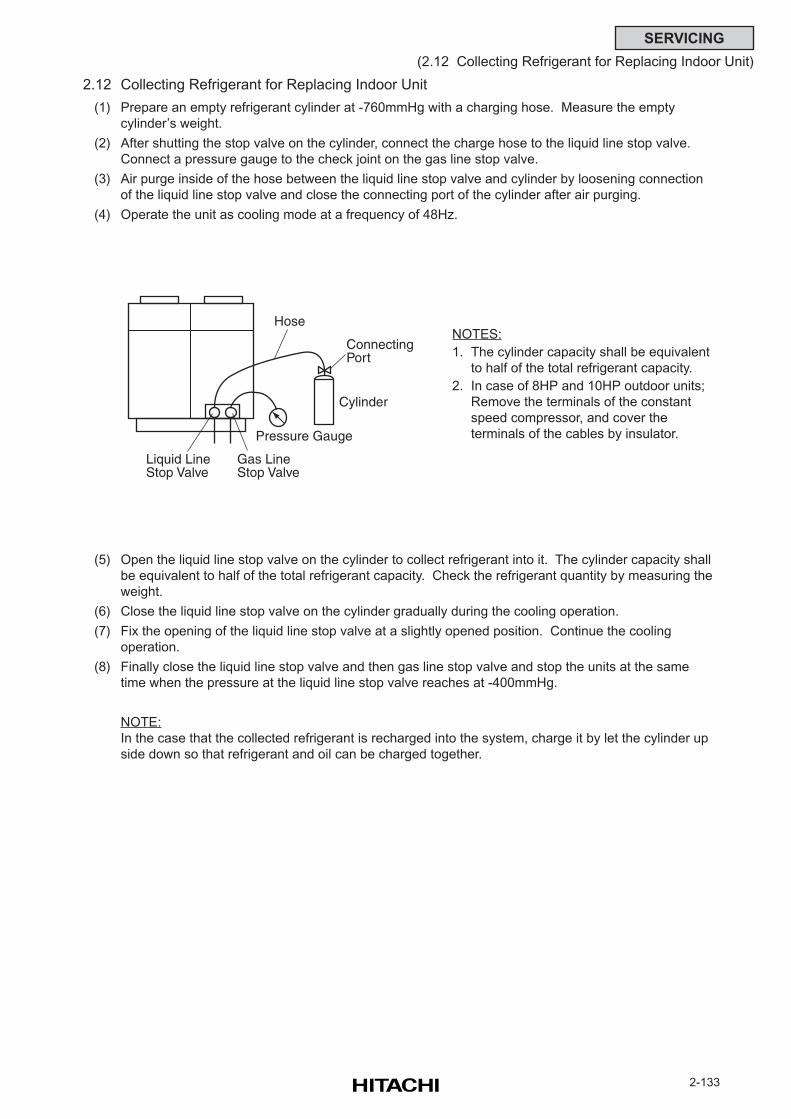
2-133
SERVICING
(2.12 Collecting Refrigerant for Replacing Indoor Unit)
2.12 Collecting Refrigerant for Replacing Indoor Unit
(1) Prepare an empty refrigerant cylinder at -760mmHg with a charging hose. Measure the empty
cylinder’s weight.
(2) After shutting the stop valve on the cylinder, connect the charge hose to the liquid line stop valve.
Connect a pressure gauge to the check joint on the gas line stop valve.
(3) Air purge inside of the hose between the liquid line stop valve and cylinder by loosening connection
of the liquid line stop valve and close the connecting port of the cylinder after air purging.
(4) Operate the unit as cooling mode at a frequency of 48Hz.
(5) Open the liquid line stop valve on the cylinder to collect refrigerant into it. The cylinder capacity shall
be equivalent to half of the total refrigerant capacity. Check the refrigerant quantity by measuring the
weight.
(6) Close the liquid line stop valve on the cylinder gradually during the cooling operation.
(7) Fix the opening of the liquid line stop valve at a slightly opened position. Continue the cooling
operation.
(8) Finally close the liquid line stop valve and then gas line stop valve and stop the units at the same
time when the pressure at the liquid line stop valve reaches at -400mmHg.
NOTE:
In the case that the collected refrigerant is recharged into the system, charge it by let the cylinder up
side down so that refrigerant and oil can be charged together.
NOTES:
1. The cylinder capacity shall be equivalent
to half of the total refrigerant capacity.
2. In case of 8HP and 10HP outdoor units;
Remove the terminals of the constant
speed compressor, and cover the
terminals of the cables by insulator.
ConnectingPort
Hose
Liquid LineStop Valve
Gas LineStop Valve
Pressure Gauge
Cylinder

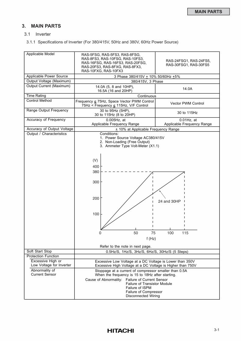
3-1
MAIN PARTS
3. MAIN PARTS
3.1 Inverter
3.1.1 Specifications of Inverter (For 380/415V, 50Hz and 380V, 60Hz Power Source)
RAS-24FSG1, RAS-24FS5,RAS-30FSG1, RAS-30FS5
14.0A
Vector PWM Control
30 to 115Hz
0.01Hz, at Applicable Frequency Range
Excessive High orLow Voltage for Inverter
Abnormality ofCurrent Sensor
Cause of Abnormality: Failure of Current SensorFailure of Transistor ModuleFailure of ISPMFailure of CompressorDisconnected Wiring
Stoppage at a current of compressor smaller than 0.5AWhen the frequency is 15 to 18Hz after starting.
Refer to the note in next page.
RAS-5FSG, RAS-5FS3, RAS-8FSG, RAS-8FS3, RAS-10FSG, RAS-10FS3, RAS-16FSG, RAS-16FS3, RAS-20FSG, RAS-20FS3, RAS-8FXG, RAS-8FX3, RAS-10FXG, RAS-10FX3
Conditions:1. Power Source Voltage AC380/415V2. Non-Loading (Free Output)3. Ammeter Type Volt-Meter (X1.1)
Excessive Low Voltage at a DC Voltage is Lower than 350VExcessive High Voltage at a DC Voltage is Higher than 750V
+ 10% at Applicable Frequency Range
0.5Hz/S, 1Hz/S, 3Hz/S, 6Hz/S, 30Hz/S (5 Steps)
Frequency < 75Hz, Space Vector PWM Control75Hz < Frequency < 115Hz, V/F Control
30 to 95Hz (5HP),30 to 115Hz (8 to 20HP)
Control Method
Output / Characteristics
Applicable Model
Applicable Power Source
Output Voltage (Maximum)
Output Current (Maximum)
Accuracy of Output Voltage
Protection Function
0.005Hz, at Applicable Frequency Range
14.0A (5, 8 and 10HP),16.5A (16 and 20HP)
3 Phase 380/415V + 10% 50/60Hz +5%
380/415V, 3 Phase
Continuous
Soft Start Stop
Time Rating
Range Output Frequency
Accuracy of Frequency
(V)
400380
300
200
100
0 50 75 100 115
24 and 30HP
f (Hz)
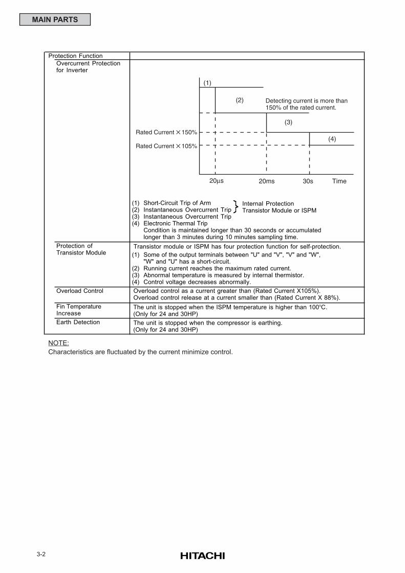
3-2
MAIN PARTS
NOTE:
Characteristics are fluctuated by the current minimize control.
Overcurrent Protectionfor Inverter
(1)(2)(3)(4)
Short-Circuit Trip of ArmInstantaneous Overcurrent TripInstantaneous Overcurrent TripElectronic Thermal TripCondition is maintained longer than 30 seconds or accumulatedlonger than 3 minutes during 10 minutes sampling time.
(1)
(2)(3)(4)
Some of the output terminals between "U" and "V", "V" and "W","W" and "U" has a short-circuit.Running current reaches the maximum rated current.Abnormal temperature is measured by internal thermistor.Control voltage decreases abnormally.
Overload Control
Fin TemperatureIncrease
Earth Detection
Protection Function
Transistor module or ISPM has four protection function for self-protection.Protection ofTransistor Module
The unit is stopped when the ISPM temperature is higher than 100oC. (Only for 24 and 30HP)
The unit is stopped when the compressor is earthing. (Only for 24 and 30HP)
Overload control as a current greater than (Rated Current X105%). Overload control release at a current smaller than (Rated Current X 88%).
Internal ProtectionTransistor Module or ISPM
20µs 20ms 30s Time
(1)
(2)
(3)
Detecting current is more than150% of the rated current.
Rated Current 150%
Rated Current 105%(4)
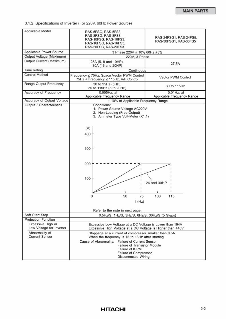
3-3
MAIN PARTS
3.1.2 Specifications of Inverter (For 220V, 60Hz Power Source)
RAS-24FSG1, RAS-24FS5,RAS-30FSG1, RAS-30FS5
27.5A
Vector PWM Control
30 to 115Hz
0.01Hz, at Applicable Frequency Range
Excessive High orLow Voltage for Inverter
Abnormality ofCurrent Sensor
Cause of Abnormality:
Protection Function
0.005Hz, at Applicable Frequency Range
25A (5, 8 and 10HP),30A (16 and 20HP)
3 Phase 220V + 10% 60Hz +5%
220V, 3 Phase
Continuous
Soft Start Stop
Time Rating
Range Output Frequency
Accuracy of Frequency
Control Method
Output / Characteristics
Applicable Model
Applicable Power Source
Output Voltage (Maximum)
Output Current (Maximum)
Accuracy of Output Voltage
Failure of Current SensorFailure of Transistor ModuleFailure of ISPMFailure of CompressorDisconnected Wiring
Stoppage at a current of compressor smaller than 0.5AWhen the frequency is 15 to 18Hz after starting.
Refer to the note in next page.
RAS-5FSG, RAS-5FS3, RAS-8FSG, RAS-8FS3, RAS-10FSG, RAS-10FS3, RAS-16FSG, RAS-16FS3, RAS-20FSG, RAS-20FS3
Conditions:1. Power Source Voltage AC220V2. Non-Loading (Free Output)3. Ammeter Type Volt-Meter (X1.1)
Excessive Low Voltage at a DC Voltage is Lower than 194VExcessive High Voltage at a DC Voltage is Higher than 440V
+ 10% at Applicable Frequency Range
0.5Hz/S, 1Hz/S, 3Hz/S, 6Hz/S, 30Hz/S (5 Steps)
Frequency < 75Hz, Space Vector PWM Control75Hz < Frequency < 115Hz, V/F Control
30 to 95Hz (5HP),30 to 115Hz (8 to 20HP)
(V)
400
300
200
100
0 50 75 100 115
f (Hz)
24 and 30HP
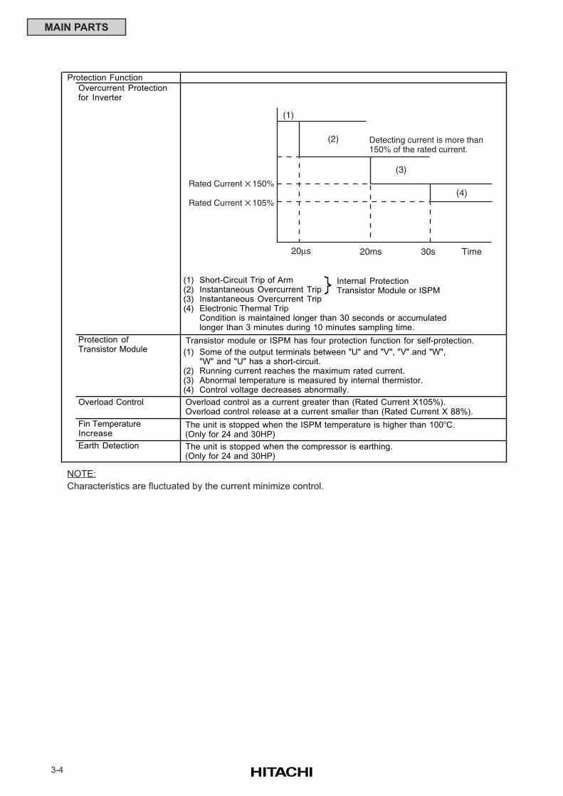
3-4
MAIN PARTS
NOTE:
Characteristics are fluctuated by the current minimize control.
Overcurrent Protectionfor Inverter
(1)(2)(3)(4)
Short-Circuit Trip of ArmInstantaneous Overcurrent TripInstantaneous Overcurrent TripElectronic Thermal TripCondition is maintained longer than 30 seconds or accumulatedlonger than 3 minutes during 10 minutes sampling time.
(1)
(2)(3)(4)
Some of the output terminals between "U" and "V", "V" and "W","W" and "U" has a short-circuit.Running current reaches the maximum rated current.Abnormal temperature is measured by internal thermistor.Control voltage decreases abnormally.
Overload Control
Fin TemperatureIncrease
Earth Detection
Protection Function
Transistor module or ISPM has four protection function for self-protection.Protection ofTransistor Module
The unit is stopped when the ISPM temperature is higher than 100oC. (Only for 24 and 30HP)
The unit is stopped when the compressor is earthing. (Only for 24 and 30HP)
Overload control as a current greater than (Rated Current X105%). Overload control release at a current smaller than (Rated Current X 88%).
Internal ProtectionTransistor Module or ISPM
20µs 20ms 30s Time
(1)
(2)
(3)
Detecting current is more than150% of the rated current.
Rated Current 150%
Rated Current 105%(4)
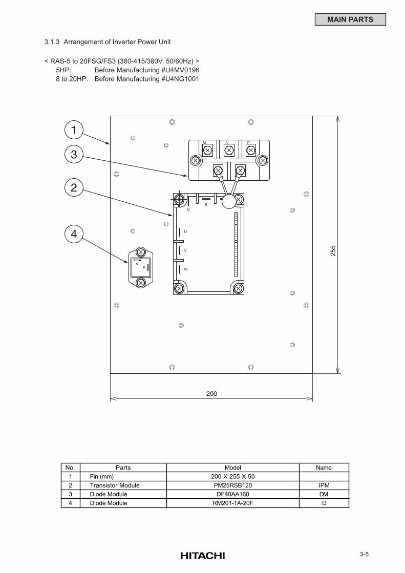
3-5
MAIN PARTS
3.1.3 Arrangement of Inverter Power Unit
200
255
AK
W V U
NB
U
V
W
1
3
2
4
< RAS-5 to 20FSG/FS3 (380-415/380V, 50/60Hz) >
5HP: Before Manufacturing #U4MV0196
8 to 20HP: Before Manufacturing #U4NG1001
No. Parts Model Name
1 Fin (mm) 200 X 255 X 50 -
2 Transistor Module PM25RSB120 IPM
3 Diode Module DF40AA160 DM
4 Diode Module RM201-1A-20F D
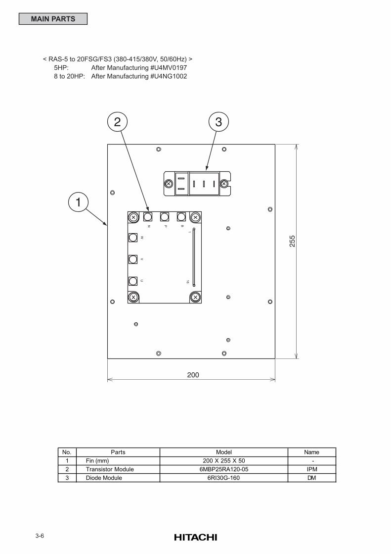
3-6
MAIN PARTS
1
32
UV
W
N P B
116
200
255
< RAS-5 to 20FSG/FS3 (380-415/380V, 50/60Hz) >
5HP: After Manufacturing #U4MV0197
8 to 20HP: After Manufacturing #U4NG1002
No. Parts Model Name
1 Fin (mm) 200 X 255 X 50 -
2 Transistor Module 6MBP25RA120-05 IPM
3 Diode Module 6RI30G-160 DM
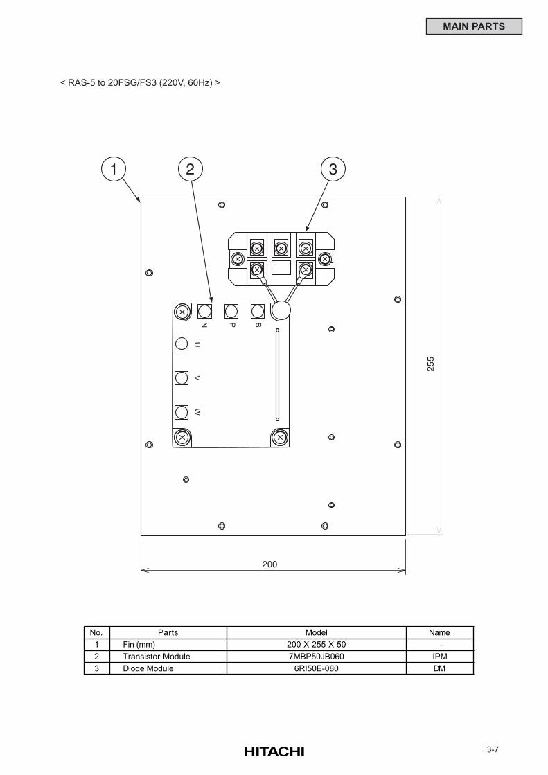
3-7
MAIN PARTS
UV
WN P B
200
1 32
255
< RAS-5 to 20FSG/FS3 (220V, 60Hz) >
No. Parts Model Name
1 Fin (mm) 200 X 255 X 50 -
2 Transistor Module 7MBP50JB060 IPM
3 Diode Module 6RI50E-080 DM
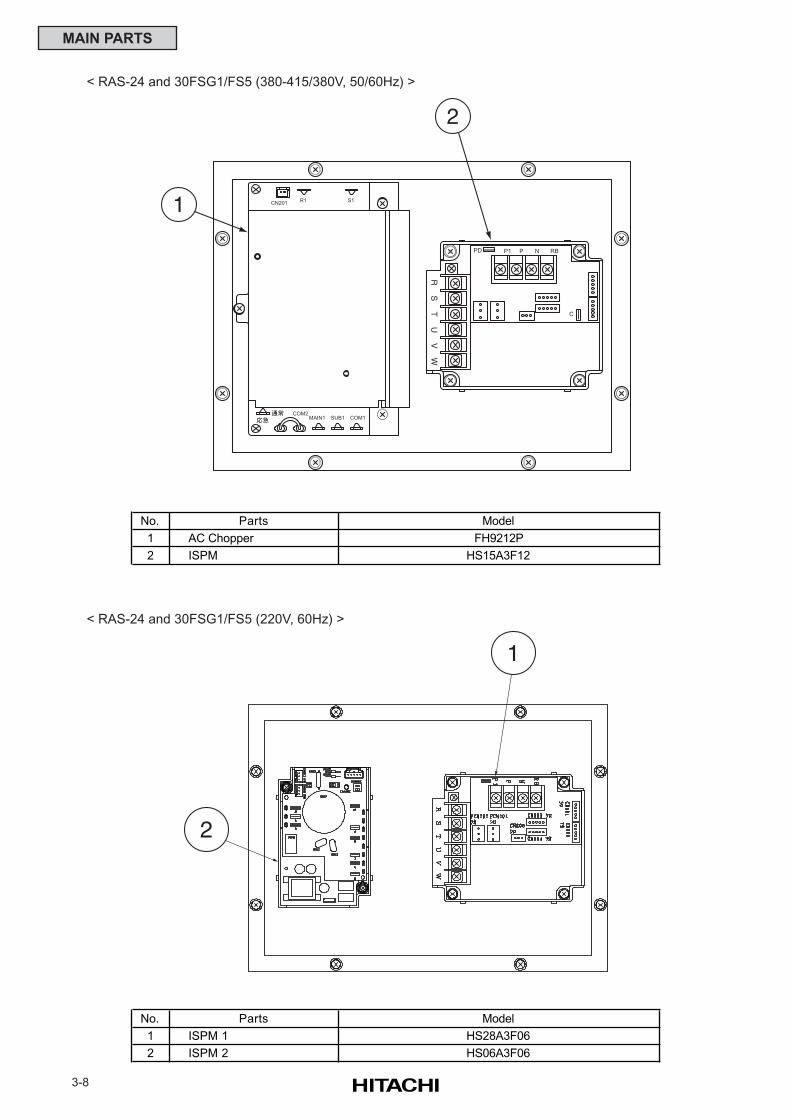
3-8
MAIN PARTS
RS
TU
VW
1
2
COM1SUB1MAIN1COM2
R1CN201 S1
RBNPP1PD
C
< RAS-24 and 30FSG1/FS5 (380-415/380V, 50/60Hz) >
No. Parts Model
1 AC Chopper FH9212P
2 ISPM HS15A3F12
1
2
< RAS-24 and 30FSG1/FS5 (220V, 60Hz) >
No. Parts Model
1 ISPM 1 HS28A3F06
2 ISPM 2 HS06A3F06
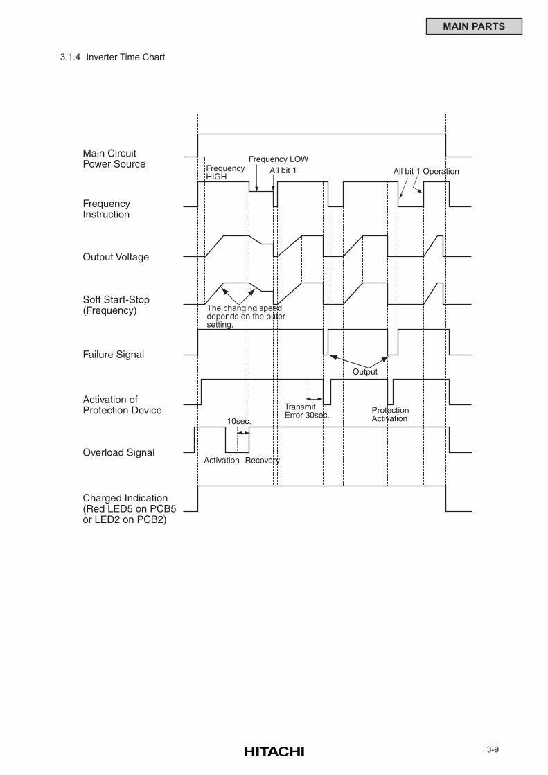
3-9
MAIN PARTS
3.1.4 Inverter Time Chart
FrequencyHIGH
Frequency LOWAll bit 1 All bit 1 Operation
The changing speeddepends on the outersetting.
TransmitError 30sec.
Activation Recovery
10sec.ProtectionActivation
Output
Main CircuitPower Source
FrequencyInstruction
Output Voltage
Soft Start-Stop(Frequency)
Failure Signal
Activation ofProtection Device
Overload Signal
Charged Indication(Red LED5 on PCB5or LED2 on PCB2)
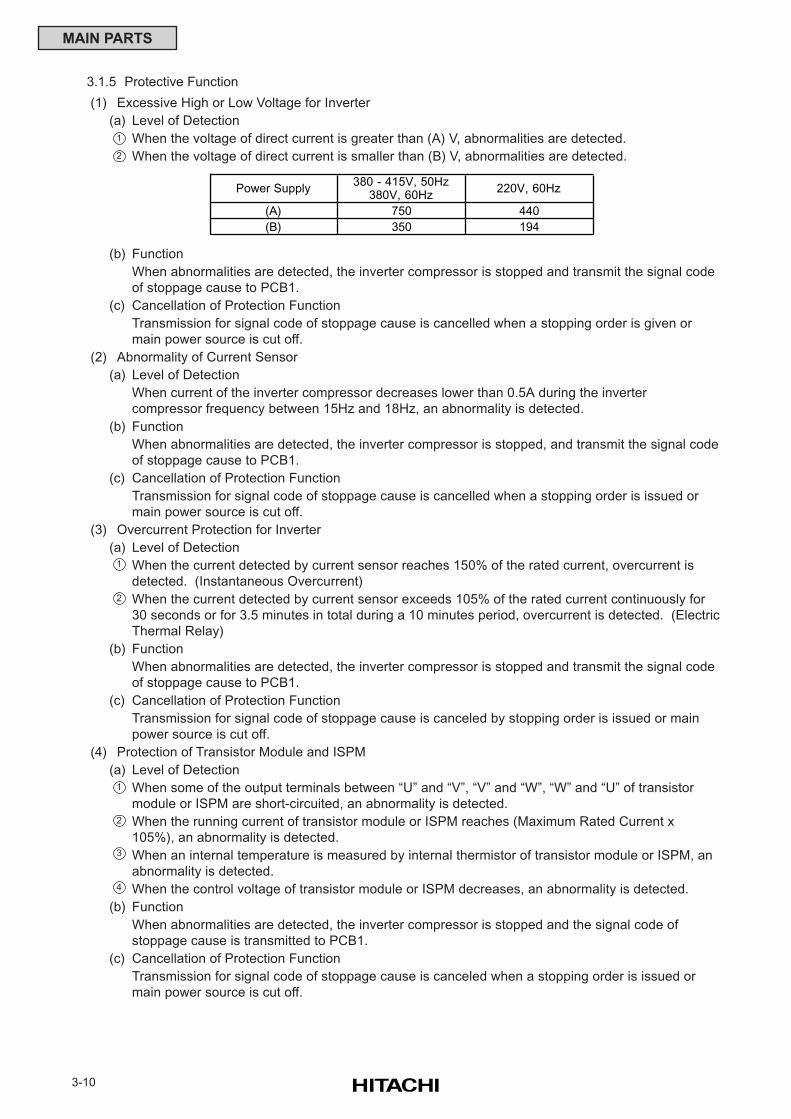
3-10
MAIN PARTS
1
2
3
4
3.1.5 Protective Function
(1) Excessive High or Low Voltage for Inverter
(a) Level of Detection
When the voltage of direct current is greater than (A) V, abnormalities are detected.
When the voltage of direct current is smaller than (B) V, abnormalities are detected.
(b) Function
When abnormalities are detected, the inverter compressor is stopped and transmit the signal code
of stoppage cause to PCB1.
(c) Cancellation of Protection Function
Transmission for signal code of stoppage cause is cancelled when a stopping order is given or
main power source is cut off.
(2) Abnormality of Current Sensor
(a) Level of Detection
When current of the inverter compressor decreases lower than 0.5A during the inverter
compressor frequency between 15Hz and 18Hz, an abnormality is detected.
(b) Function
When abnormalities are detected, the inverter compressor is stopped, and transmit the signal code
of stoppage cause to PCB1.
(c) Cancellation of Protection Function
Transmission for signal code of stoppage cause is cancelled when a stopping order is issued or
main power source is cut off.
(3) Overcurrent Protection for Inverter
(a) Level of Detection
When the current detected by current sensor reaches 150% of the rated current, overcurrent is
detected. (Instantaneous Overcurrent)
When the current detected by current sensor exceeds 105% of the rated current continuously for
30 seconds or for 3.5 minutes in total during a 10 minutes period, overcurrent is detected. (Electric
Thermal Relay)
(b) Function
When abnormalities are detected, the inverter compressor is stopped and transmit the signal code
of stoppage cause to PCB1.
(c) Cancellation of Protection Function
Transmission for signal code of stoppage cause is canceled by stopping order is issued or main
power source is cut off.
(4) Protection of Transistor Module and ISPM
(a) Level of Detection
When some of the output terminals between “U” and “V”, “V” and “W”, “W” and “U” of transistor
module or ISPM are short-circuited, an abnormality is detected.
When the running current of transistor module or ISPM reaches (Maximum Rated Current x
105%), an abnormality is detected.
When an internal temperature is measured by internal thermistor of transistor module or ISPM, an
abnormality is detected.
When the control voltage of transistor module or ISPM decreases, an abnormality is detected.
(b) Function
When abnormalities are detected, the inverter compressor is stopped and the signal code of
stoppage cause is transmitted to PCB1.
(c) Cancellation of Protection Function
Transmission for signal code of stoppage cause is canceled when a stopping order is issued or
main power source is cut off.
1
2
1
2
Power Supply380 - 415V, 50Hz
380V, 60Hz220V, 60Hz
(A) 750 440
(B) 350 194
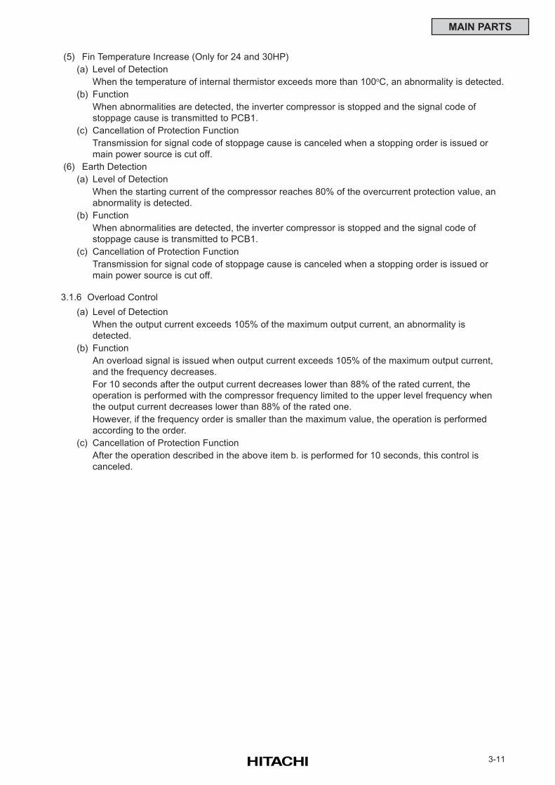
3-11
MAIN PARTS
(5) Fin Temperature Increase (Only for 24 and 30HP)
(a) Level of Detection
When the temperature of internal thermistor exceeds more than 100oC, an abnormality is detected.
(b) Function
When abnormalities are detected, the inverter compressor is stopped and the signal code of
stoppage cause is transmitted to PCB1.
(c) Cancellation of Protection Function
Transmission for signal code of stoppage cause is canceled when a stopping order is issued or
main power source is cut off.
(6) Earth Detection
(a) Level of Detection
When the starting current of the compressor reaches 80% of the overcurrent protection value, an
abnormality is detected.
(b) Function
When abnormalities are detected, the inverter compressor is stopped and the signal code of
stoppage cause is transmitted to PCB1.
(c) Cancellation of Protection Function
Transmission for signal code of stoppage cause is canceled when a stopping order is issued or
main power source is cut off.
3.1.6 Overload Control
(a) Level of Detection
When the output current exceeds 105% of the maximum output current, an abnormality is
detected.
(b) Function
An overload signal is issued when output current exceeds 105% of the maximum output current,
and the frequency decreases.
For 10 seconds after the output current decreases lower than 88% of the rated current, the
operation is performed with the compressor frequency limited to the upper level frequency when
the output current decreases lower than 88% of the rated one.
However, if the frequency order is smaller than the maximum value, the operation is performed
according to the order.
(c) Cancellation of Protection Function
After the operation described in the above item b. is performed for 10 seconds, this control is
canceled.
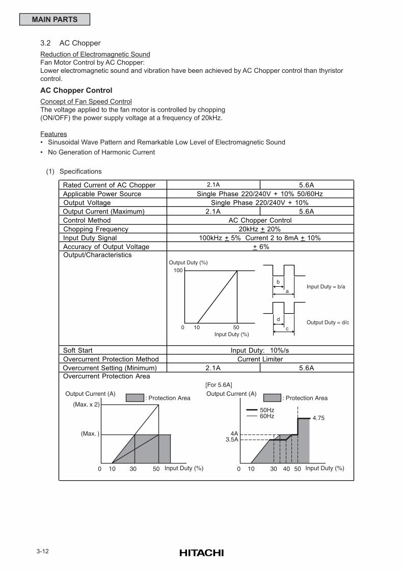
3-12
MAIN PARTS
3.2 AC Chopper
Reduction of Electromagnetic Sound
Fan Motor Control by AC Chopper:
Lower electromagnetic sound and vibration have been achieved by AC Chopper control than thyristor
control.
AC Chopper Control
Concept of Fan Speed Control
The voltage applied to the fan motor is controlled by chopping
(ON/OFF) the power supply voltage at a frequency of 20kHz.
Features
• Sinusoidal Wave Pattern and Remarkable Low Level of Electromagnetic Sound
• No Generation of Harmonic Current
(1) Specifications
Rated Current of AC Chopper 2.1A 5.6A
Applicable Power Source
Output Voltage
Output Current (Maximum) 2.1A 5.6A
Control Method
Chopping Frequency
Input Duty Signal
Accuracy of Output Voltage
Output/Characteristics
Soft Start
Overcurrent Protection Method
Overcurrent Setting (Minimum) 2.1A 5.6A
Overcurrent Protection Area
100kHz + 5% Current 2 to 8mA + 10%
+ 6%
Input Duty: 10%/s
Current Limiter
Single Phase 220/240V + 10% 50/60Hz
Single Phase 220/240V + 10%
AC Chopper Control
20kHz + 20%
(Max. x 2)
(Max. )
0 10 50
Output Current (A)
Input Duty (%)30
: Protection Area
4A
10 50
Output Current (A)
Input Duty (%)30
: Protection Area
40
50Hz60Hz
3.5A
4.75
0
[For 5.6A]
b
a
d
c
100
0 10 50
Output Duty (%)
Input Duty (%)
Input Duty = b/a
Output Duty = d/c
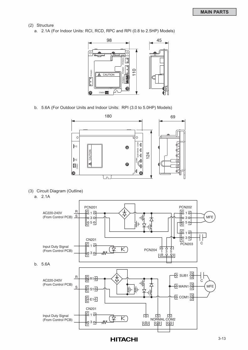
3-13
MAIN PARTS
(2) Structure
a. 2.1A (For Indoor Units: RCI, RCD, RPC and RPI (0.8 to 2.5HP) Models)
(3) Circuit Diagram (Outline)
a. 2.1A
b. 5.6A
AC220-240V(From Control PCB)
Input Duty Signal(From Control PCB)
RS
13
PCN201 PCN202
PCN203
PCN204
5
1
3
CN201
135
13
51 3
C
MFE
AC220-240V(From Control PCB)
Input Duty Signal(From Control PCB)
R
S
R1SUB1
MAIN1
1
3
CN201
C
MFE
NORMAL COM2
COM1
S1
E1
98
110
45
CAUTION
CN201P
CN
201
PC
N20
3P
CN
202
PC
N20
4
R1
CN
201
S1 CO
M1
CO
M2
SU
B1
MA
IN1
CA
UT
ION
180 69
124
b. 5.6A (For Outdoor Units and Indoor Units: RPI (3.0 to 5.0HP) Models)
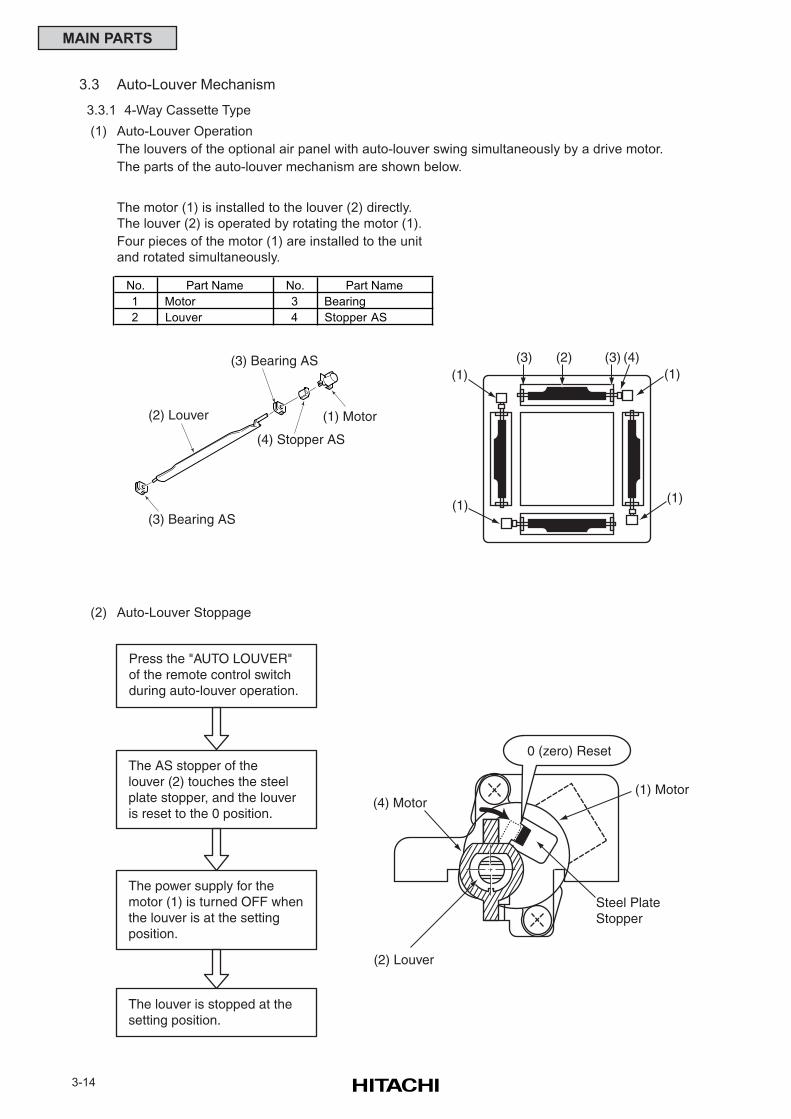
3-14
MAIN PARTS
3.3 Auto-Louver Mechanism
3.3.1 4-Way Cassette Type
(1) Auto-Louver Operation
The louvers of the optional air panel with auto-louver swing simultaneously by a drive motor.
The parts of the auto-louver mechanism are shown below.
(2) Auto-Louver Stoppage
The motor (1) is installed to the louver (2) directly.
The louver (2) is operated by rotating the motor (1).
Four pieces of the motor (1) are installed to the unit
and rotated simultaneously.
(2) Louver
(4) Stopper AS
(1) Motor
(3) Bearing AS
(3) Bearing AS
(4) Motor
0 (zero) Reset
(1) Motor
(2) Louver
Steel PlateStopper
Press the "AUTO LOUVER"of the remote control switch during auto-louver operation.
The AS stopper of thelouver (2) touches the steelplate stopper, and the louveris reset to the 0 position.
The power supply for the motor (1) is turned OFF whenthe louver is at the settingposition.
The louver is stopped at thesetting position.
(1)(2)(3) (4)
(1)
(3)(1)
(1)
No. Part Name No. Part Name
1 Motor 3 Bearing
2 Louver 4 Stopper AS
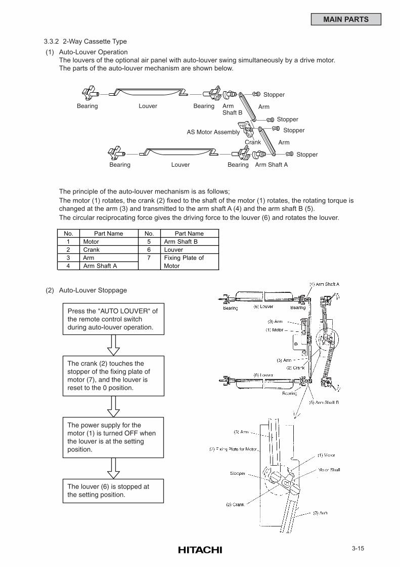
3-15
MAIN PARTS
3.3.2 2-Way Cassette Type
(1) Auto-Louver Operation
The louvers of the optional air panel with auto-louver swing simultaneously by a drive motor.
The parts of the auto-louver mechanism are shown below.
The principle of the auto-louver mechanism is as follows;
The motor (1) rotates, the crank (2) fixed to the shaft of the motor (1) rotates, the rotating torque is
changed at the arm (3) and transmitted to the arm shaft A (4) and the arm shaft B (5).
The circular reciprocating force gives the driving force to the louver (6) and rotates the louver.
(2) Auto-Louver Stoppage
Press the "AUTO LOUVER" ofthe remote control switch during auto-louver operation.
The crank (2) touches the stopper of the fixing plate ofmotor (7), and the louver isreset to the 0 position.
The power supply for the motor (1) is turned OFF whenthe louver is at the settingposition.
The louver (6) is stopped at the setting position.
Bearing Louver ArmShaft B
Arm
Stopper
Arm Shaft A
Crank
Bearing
Bearing Louver Bearing
Arm
Stopper
Stopper
AS Motor Assembly
Stopper
No. Part Name No. Part Name
1 Motor 5 Arm Shaft B
2 Crank 6 Louver
3 Arm 7 Fixing Plate of
4 Arm Shaft A Motor
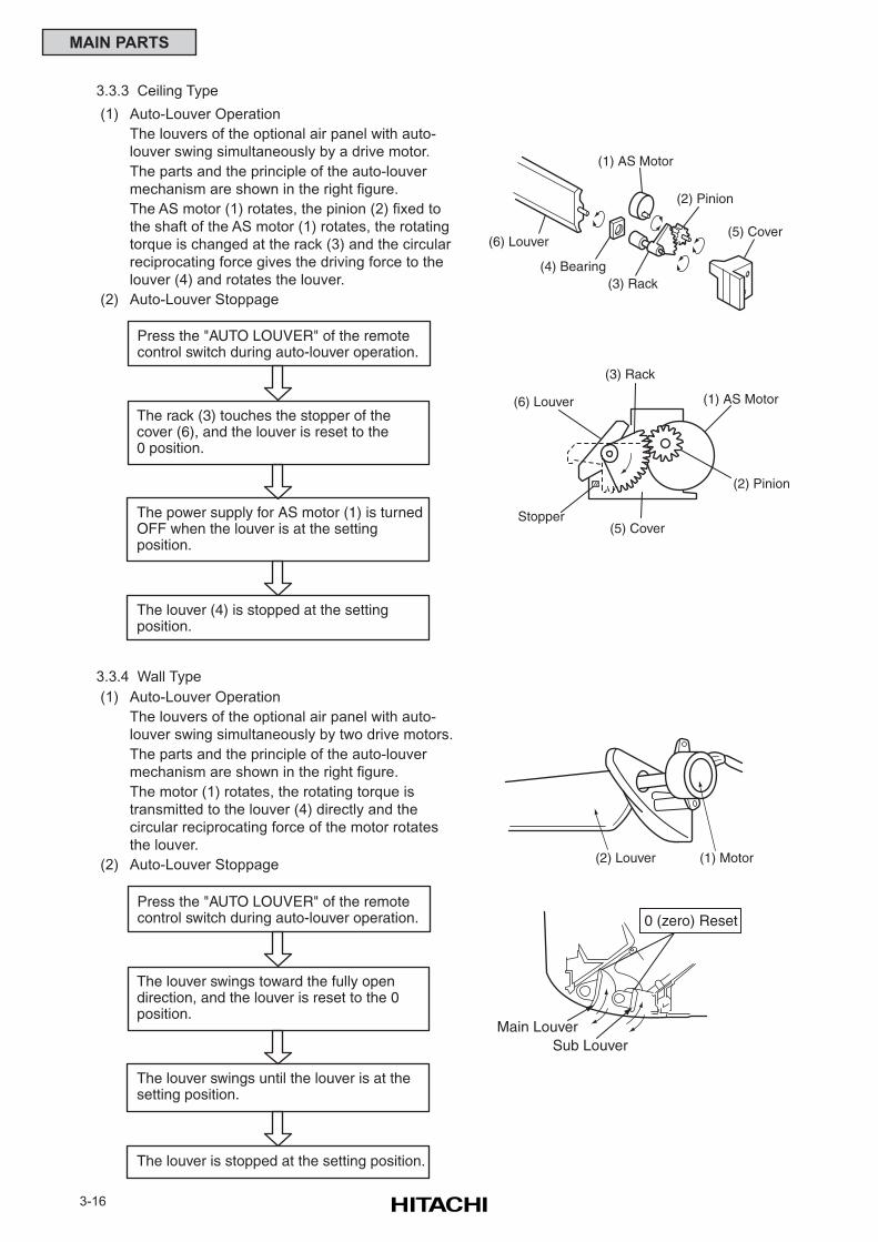
3-16
MAIN PARTS
3.3.3 Ceiling Type
(1) Auto-Louver Operation
The louvers of the optional air panel with auto-
louver swing simultaneously by a drive motor.
The parts and the principle of the auto-louver
mechanism are shown in the right figure.
The AS motor (1) rotates, the pinion (2) fixed to
the shaft of the AS motor (1) rotates, the rotating
torque is changed at the rack (3) and the circular
reciprocating force gives the driving force to the
louver (4) and rotates the louver.
(2) Auto-Louver Stoppage
3.3.4 Wall Type
(1) Auto-Louver Operation
The louvers of the optional air panel with auto-
louver swing simultaneously by two drive motors.
The parts and the principle of the auto-louver
mechanism are shown in the right figure.
The motor (1) rotates, the rotating torque is
transmitted to the louver (4) directly and the
circular reciprocating force of the motor rotates
the louver.
(2) Auto-Louver Stoppage
(1) AS Motor
(2) Pinion
(3) Rack(4) Bearing
(5) Cover(6) Louver
(1) AS Motor
(2) Pinion
(3) Rack
(6) Louver
Stopper(5) Cover
(2) Louver (1) Motor
Main LouverSub Louver
0 (zero) Reset
Press the "AUTO LOUVER" of the remotecontrol switch during auto-louver operation.
The rack (3) touches the stopper of thecover (6), and the louver is reset to the0 position.
The power supply for AS motor (1) is turnedOFF when the louver is at the settingposition.
The louver (4) is stopped at the settingposition.
Press the "AUTO LOUVER" of the remotecontrol switch during auto-louver operation.
The louver swings toward the fully opendirection, and the louver is reset to the 0position.
The louver swings until the louver is at thesetting position.
The louver is stopped at the setting position.
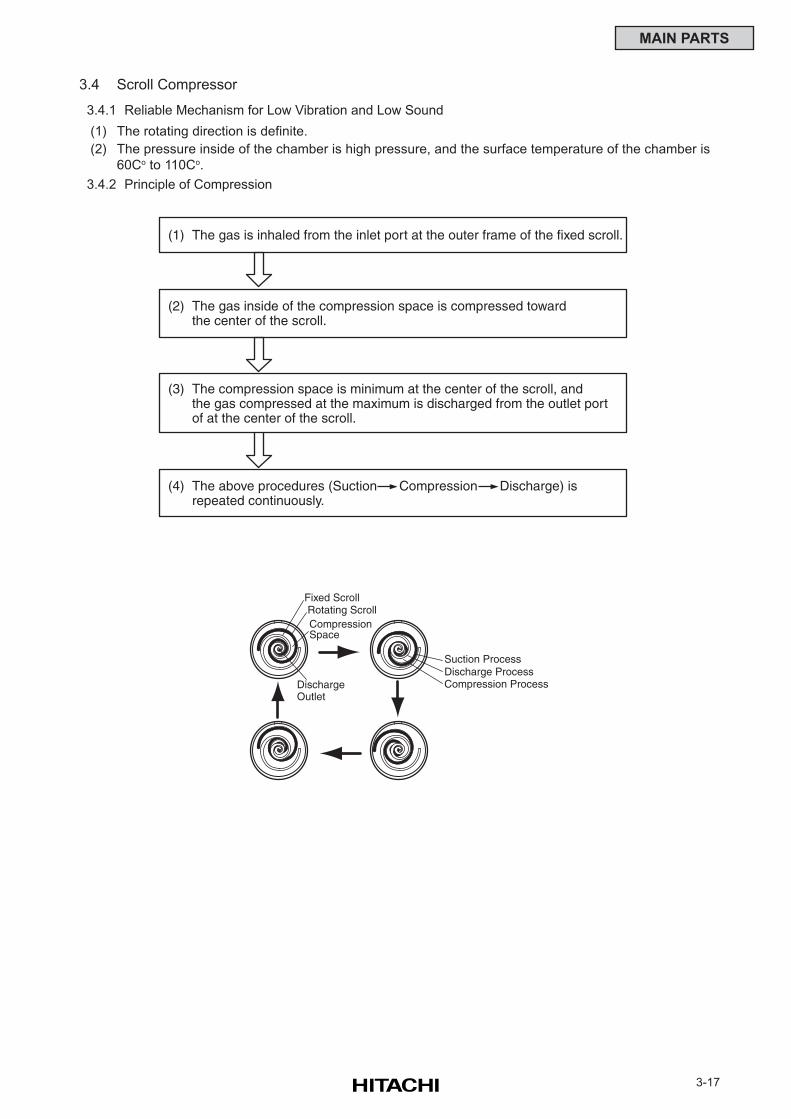
3-17
MAIN PARTS
3.4 Scroll Compressor
3.4.1 Reliable Mechanism for Low Vibration and Low Sound
(1) The rotating direction is definite.
(2) The pressure inside of the chamber is high pressure, and the surface temperature of the chamber is
60Co to 110Co.
3.4.2 Principle of Compression
(1) The gas is inhaled from the inlet port at the outer frame of the fixed scroll.
(2) The gas inside of the compression space is compressed towardthe center of the scroll.
(3) The compression space is minimum at the center of the scroll, andthe gas compressed at the maximum is discharged from the outlet port of at the center of the scroll.
(4) The above procedures (Suction Compression Discharge) isrepeated continuously.
Fixed ScrollRotating ScrollCompression Space
DischargeOutlet
Suction ProcessDischarge ProcessCompression Process
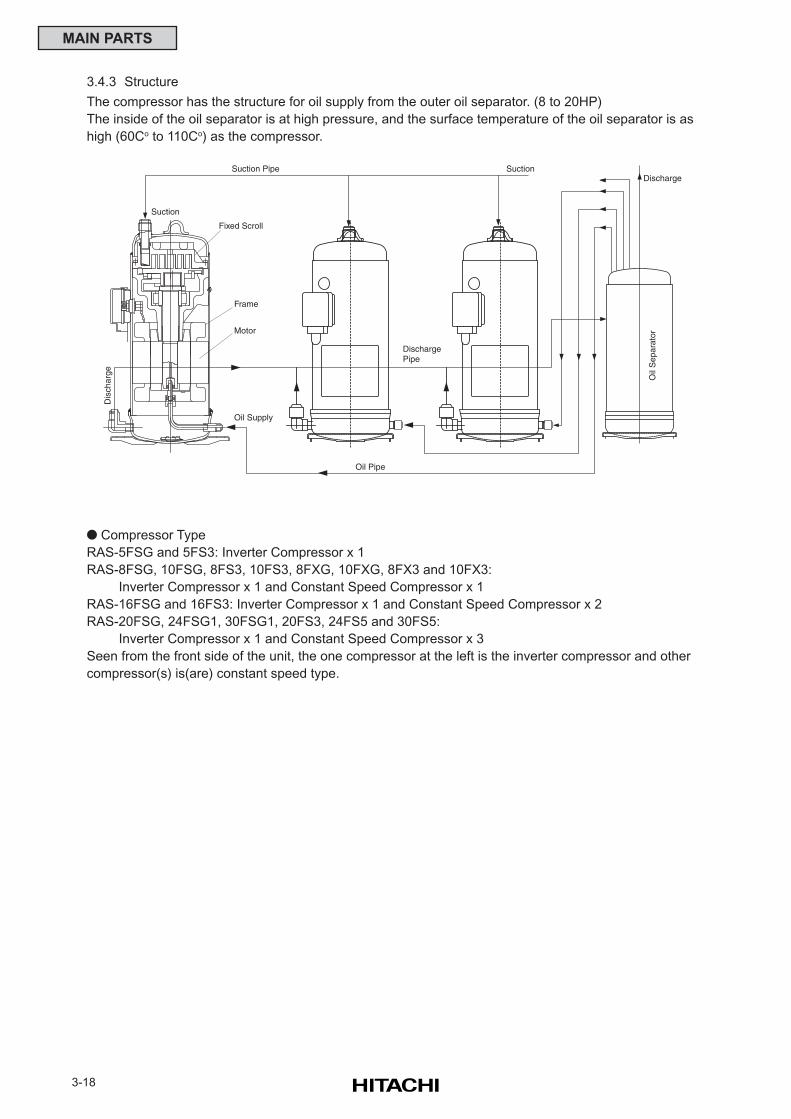
3-18
MAIN PARTS
3.4.3 Structure
The compressor has the structure for oil supply from the outer oil separator. (8 to 20HP)
The inside of the oil separator is at high pressure, and the surface temperature of the oil separator is as
high (60Co to 110Co) as the compressor.
Compressor Type
RAS-5FSG and 5FS3: Inverter Compressor x 1
RAS-8FSG, 10FSG, 8FS3, 10FS3, 8FXG, 10FXG, 8FX3 and 10FX3:
Inverter Compressor x 1 and Constant Speed Compressor x 1
RAS-16FSG and 16FS3: Inverter Compressor x 1 and Constant Speed Compressor x 2
RAS-20FSG, 24FSG1, 30FSG1, 20FS3, 24FS5 and 30FS5:
Inverter Compressor x 1 and Constant Speed Compressor x 3
Seen from the front side of the unit, the one compressor at the left is the inverter compressor and other
compressor(s) is(are) constant speed type.
Suction
Frame
Motor
Oil Supply
Oil Pipe
DischargePipe
SuctionSuction Pipe
Fixed Scroll
Dis
char
ge
Discharge
Oil
Sep
arat
or
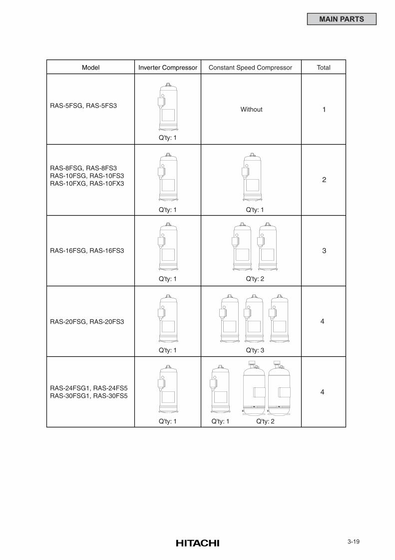
3-19
MAIN PARTS
RAS-8FSG, RAS-8FS3RAS-10FSG, RAS-10FS3RAS-10FXG, RAS-10FX3
RAS-5FSG, RAS-5FS3
RAS-16FSG, RAS-16FS3
RAS-20FSG, RAS-20FS3
Inverter Compressor Constant Speed CompressorModel
Q'ty: 1
Q'ty: 1
Q'ty: 1
Q'ty: 1
Q'ty: 1 Q'ty: 1 Q'ty: 2
Q'ty: 1
Q'ty: 2
Q'ty: 3
Total
1
2
3
4
4
Without
RAS-24FSG1, RAS-24FS5RAS-30FSG1, RAS-30FS5
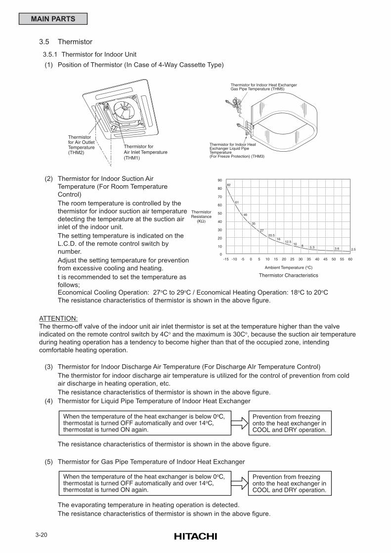
3-20
MAIN PARTS
3.5 Thermistor
3.5.1 Thermistor for Indoor Unit
(1) Position of Thermistor (In Case of 4-Way Cassette Type)
ATTENTION:
The thermo-off valve of the indoor unit air inlet thermistor is set at the temperature higher than the valve
indicated on the remote control switch by 4Co and the maximum is 30Co, because the suction air temperature
during heating operation has a tendency to become higher than that of the occupied zone, intending
comfortable heating operation.
(3) Thermistor for Indoor Discharge Air Temperature (For Discharge AIr Temperature Control)
The thermistor for indoor discharge air temperature is utilized for the control of prevention from cold
air discharge in heating operation, etc.
The resistance characteristics of thermistor is shown in the above figure.
(4) Thermistor for Liquid Pipe Temperature of Indoor Heat Exchanger
The resistance characteristics of thermistor is shown in the above figure.
(5) Thermistor for Gas Pipe Temperature of Indoor Heat Exchanger
The evaporating temperature in heating operation is detected.
The resistance characteristics of thermistor is shown in the above figure.
When the temperature of the heat exchanger is below 0oC,thermostat is turned OFF automatically and over 14oC,thermostat is turned ON again.
Prevention from freezingonto the heat exchanger inCOOL and DRY operation.
When the temperature of the heat exchanger is below 0oC,thermostat is turned OFF automatically and over 14oC,thermostat is turned ON again.
Prevention from freezingonto the heat exchanger inCOOL and DRY operation.
0
10
20
30
40
50
60
70
80
-15 -10 -5 0 5 10 15 20 25 30 35 40 45 50 55 60
82
61
46
35
27
20.516
12.510 8 5.3 3.6 2.5
90
Ambient Temperature (oC)
ThermistorResistance
(KΩ)
Thermistor Characteristics
Thermistor forAir Inlet Temperature(THM1)
Thermistorfor Air OutletTemperature(THM2)
Thermistor for Indoor Heat Exchanger Gas Pipe Temperature (THM5)
Thermistor for Indoor HeatExchanger Liquid PipeTemperature(For Freeze Protection) (THM3)
(2) Thermistor for Indoor Suction Air
Temperature (For Room Temperature
Control)
The room temperature is controlled by the
thermistor for indoor suction air temperature
detecting the temperature at the suction air
inlet of the indoor unit.
The setting temperature is indicated on the
L.C.D. of the remote control switch by
number.
Adjust the setting temperature for prevention
from excessive cooling and heating.
t is recommended to set the temperature as
follows;Economical Cooling Operation: 27oC to 29oC / Economical Heating Operation: 18oC to 20oC
The resistance characteristics of thermistor is shown in the above figure.
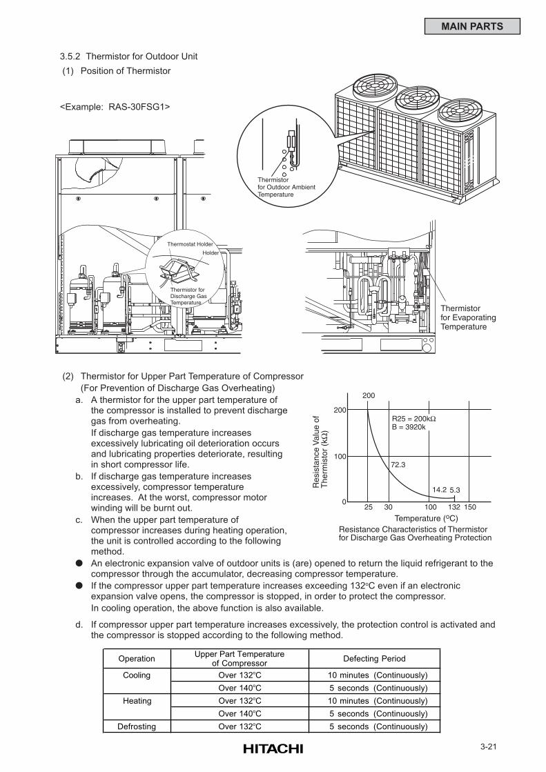
3-21
MAIN PARTS
3.5.2 Thermistor for Outdoor Unit
(1) Position of Thermistor
(2) Thermistor for Upper Part Temperature of Compressor
(For Prevention of Discharge Gas Overheating)
a. A thermistor for the upper part temperature ofthe compressor is installed to prevent dischargegas from overheating.
If discharge gas temperature increasesexcessively lubricating oil deterioration occursand lubricating properties deteriorate, resultingin short compressor life.
b. If discharge gas temperature increasesexcessively, compressor temperatureincreases. At the worst, compressor motorwinding will be burnt out.
c. When the upper part temperature ofcompressor increases during heating operation,the unit is controlled according to the followingmethod.
An electronic expansion valve of outdoor units is (are) opened to return the liquid refrigerant to thecompressor through the accumulator, decreasing compressor temperature.
If the compressor upper part temperature increases exceeding 132oC even if an electronicexpansion valve opens, the compressor is stopped, in order to protect the compressor.
In cooling operation, the above function is also available.
200
100
25 30 132 150
72.3
14.2
100
200
5.3Res
ista
nce
Val
ue o
fT
herm
isto
r (k
Ω)
Temperature (oC)Resistance Characteristics of Thermistorfor Discharge Gas Overheating Protection
R25 = 200kΩB = 3920k
0
d. If compressor upper part temperature increases excessively, the protection control is activated andthe compressor is stopped according to the following method.
OperationUpper Part Temperature
of Compressor
Cooling Over 132oC 10 minutes (Continuously)
Over 140oC 5 seconds (Continuously)
Heating Over 132oC 10 minutes (Continuously)
Over 140oC 5 seconds (Continuously)
Defrosting Over 132oC 5 seconds (Continuously)
Defecting Period
Thermostat Holder
Holder
Thermistor forDischarge GasTemperature
Thermistorfor EvaporatingTemperature
Thermistorfor Outdoor AmbientTemperature
<Example: RAS-30FSG1>
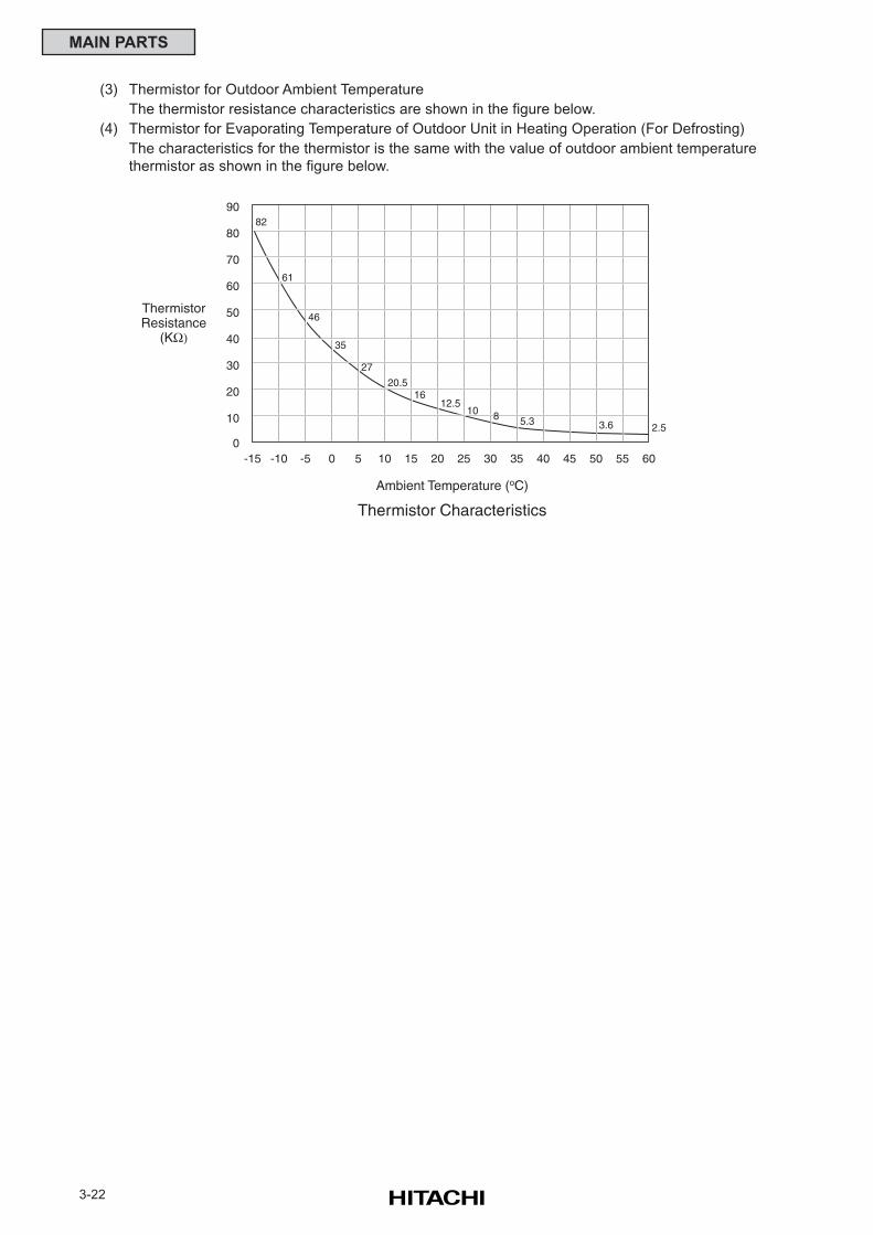
3-22
MAIN PARTS
(3) Thermistor for Outdoor Ambient Temperature
The thermistor resistance characteristics are shown in the figure below.
(4) Thermistor for Evaporating Temperature of Outdoor Unit in Heating Operation (For Defrosting)
The characteristics for the thermistor is the same with the value of outdoor ambient temperature
thermistor as shown in the figure below.
0
10
20
30
40
50
60
70
80
-15 -10 -5 0 5 10 15 20 25 30 35 40 45 50 55 60
82
61
46
35
27
20.516
12.510 8 5.3 3.6 2.5
90
Ambient Temperature (oC)
ThermistorResistance
(KΩ)
Thermistor Characteristics
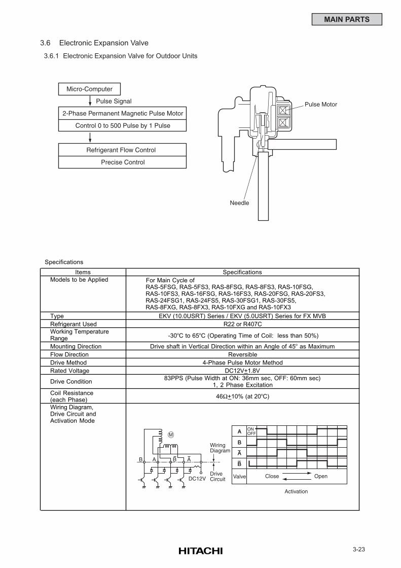
3-23
MAIN PARTS
3.6 Electronic Expansion Valve
3.6.1 Electronic Expansion Valve for Outdoor Units
Micro-Computer
Pulse Signal
2-Phase Permanent Magnetic Pulse Motor
Control 0 to 500 Pulse by 1 Pulse
Refrigerant Flow Control
Precise Control
Pulse Motor
Needle
Specifications
Items Specifications
Models to be Applied For Main Cycle of RAS-5FSG, RAS-5FS3, RAS-8FSG, RAS-8FS3, RAS-10FSG, RAS-10FS3, RAS-16FSG, RAS-16FS3, RAS-20FSG, RAS-20FS3, RAS-24FSG1, RAS-24FS5, RAS-30FSG1, RAS-30FS5, RAS-8FXG, RAS-8FX3, RAS-10FXG and RAS-10FX3
Type EKV (10.0USRT) Series / EKV (5.0USRT) Series for FX MVB
Refrigerant Used R22 or R407C
Working TemperatureRange -30oC to 65oC (Operating Time of Coil: less than 50%)
Mounting Direction Drive shaft in Vertical Direction within an Angle of 45o as Maximum
Flow Direction Reversible
Drive Method 4-Phase Pulse Motor Method
Rated Voltage DC12V+1.8V
Drive Condition83PPS (Pulse Width at ON: 36mm sec, OFF: 60mm sec)
1, 2 Phase Excitation
Coil Resistance(each Phase)
46Ω+10% (at 20oC)
Wiring Diagram,Drive Circuit andActivation Mode
DC12V
WiringDiagram
DriveCircuit
MONOFFA
Valve Close Open
Activation
B
A
BAB
A
B
A
BAB
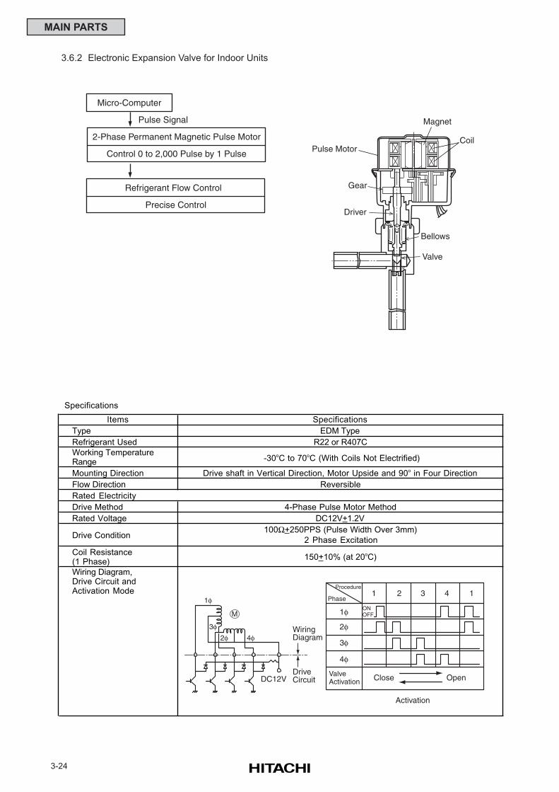
3-24
MAIN PARTS
3.6.2 Electronic Expansion Valve for Indoor Units
Micro-Computer
Pulse Signal
2-Phase Permanent Magnetic Pulse Motor
Control 0 to 2,000 Pulse by 1 Pulse
Refrigerant Flow Control
Precise Control
Pulse Motor
Gear
Driver
Valve
Bellows
Coil
Magnet
DC12V
WiringDiagram
DriveCircuit
4φ2φ3φ
1φ
MONOFF
ValveActivation Close Open
Activation
Procedure
Phase
2φ
4φ
3φ
1φ
1 2 3 4 1
Specifications
Items Specifications
Type EDM Type
Refrigerant Used R22 or R407C
Working TemperatureRange -30oC to 70oC (With Coils Not Electrified)
Mounting Direction Drive shaft in Vertical Direction, Motor Upside and 90o in Four Direction
Flow Direction Reversible
Rated Electricity
Drive Method 4-Phase Pulse Motor Method
Rated Voltage DC12V+1.2V
Drive Condition100Ω+250PPS (Pulse Width Over 3mm)
2 Phase Excitation
Coil Resistance(1 Phase)
150+10% (at 20oC)
Wiring Diagram,Drive Circuit andActivation Mode
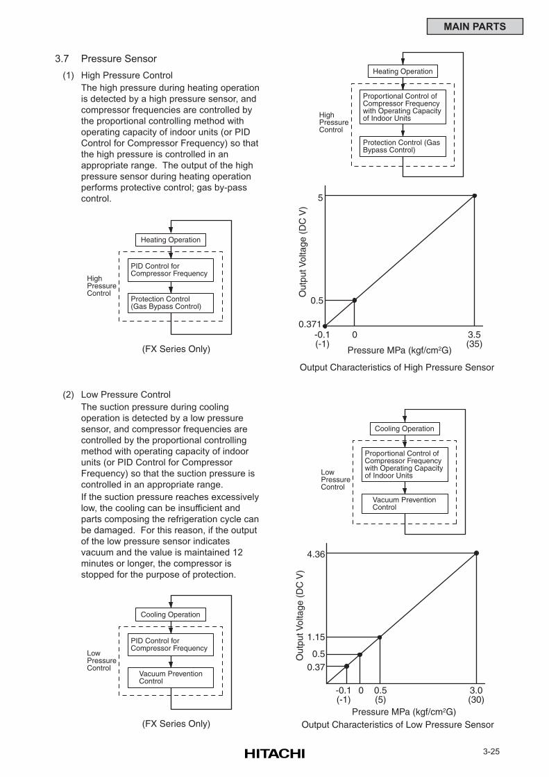
3-25
MAIN PARTS
3.7 Pressure Sensor
(1) High Pressure Control
The high pressure during heating operation
is detected by a high pressure sensor, and
compressor frequencies are controlled by
the proportional controlling method with
operating capacity of indoor units (or PID
Control for Compressor Frequency) so that
the high pressure is controlled in an
appropriate range. The output of the high
pressure sensor during heating operation
performs protective control; gas by-pass
control.
(2) Low Pressure Control
The suction pressure during cooling
operation is detected by a low pressure
sensor, and compressor frequencies are
controlled by the proportional controlling
method with operating capacity of indoor
units (or PID Control for Compressor
Frequency) so that the suction pressure is
controlled in an appropriate range.
If the suction pressure reaches excessively
low, the cooling can be insufficient and
parts composing the refrigeration cycle can
be damaged. For this reason, if the output
of the low pressure sensor indicates
vacuum and the value is maintained 12
minutes or longer, the compressor is
stopped for the purpose of protection.
5
0.5
0.371-0.1(-1)
0 3.5(35)
Out
put V
olta
ge (
DC
V)
Pressure MPa (kgf/cm2G)
Heating Operation
Proportional Control ofCompressor Frequencywith Operating Capacityof Indoor Units
Protection Control (GasBypass Control)
Output Characteristics of High Pressure Sensor
HighPressureControl
4.36
0.50.37
-0.1(-1)
0 3.0(30)
Out
put V
olta
ge (
DC
V)
Pressure MPa (kgf/cm2G)
Cooling Operation
Proportional Control ofCompressor Frequencywith Operating Capacityof Indoor Units
Vacuum PreventionControl
Output Characteristics of Low Pressure Sensor
LowPressureControl
1.15
0.5(5)
Heating Operation
PID Control for Compressor Frequency
Protection Control(Gas Bypass Control)
HighPressureControl
(FX Series Only)
Cooling Operation
PID Control for Compressor Frequency
Vacuum PreventionControl
LowPressureControl
(FX Series Only)
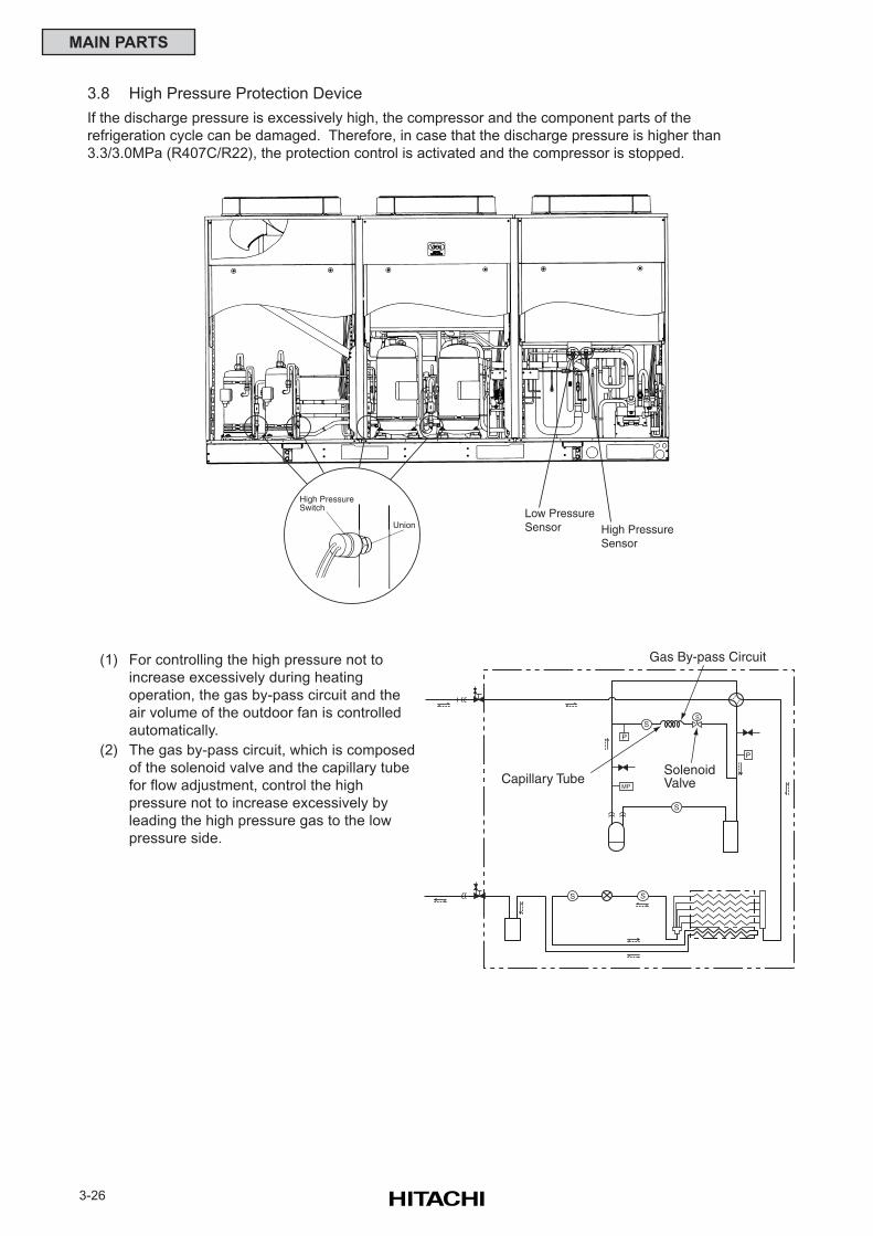
3-26
MAIN PARTS
3.8 High Pressure Protection Device
If the discharge pressure is excessively high, the compressor and the component parts of the
refrigeration cycle can be damaged. Therefore, in case that the discharge pressure is higher than
3.3/3.0MPa (R407C/R22), the protection control is activated and the compressor is stopped.
(1) For controlling the high pressure not to
increase excessively during heating
operation, the gas by-pass circuit and the
air volume of the outdoor fan is controlled
automatically.
(2) The gas by-pass circuit, which is composed
of the solenoid valve and the capillary tube
for flow adjustment, control the high
pressure not to increase excessively by
leading the high pressure gas to the low
pressure side.
Low PressureSensor High Pressure
Sensor
High PressureSwitch
Union
MP
P
P
S
S
SolenoidValve
Gas By-pass Circuit
Capillary Tube
S
S S
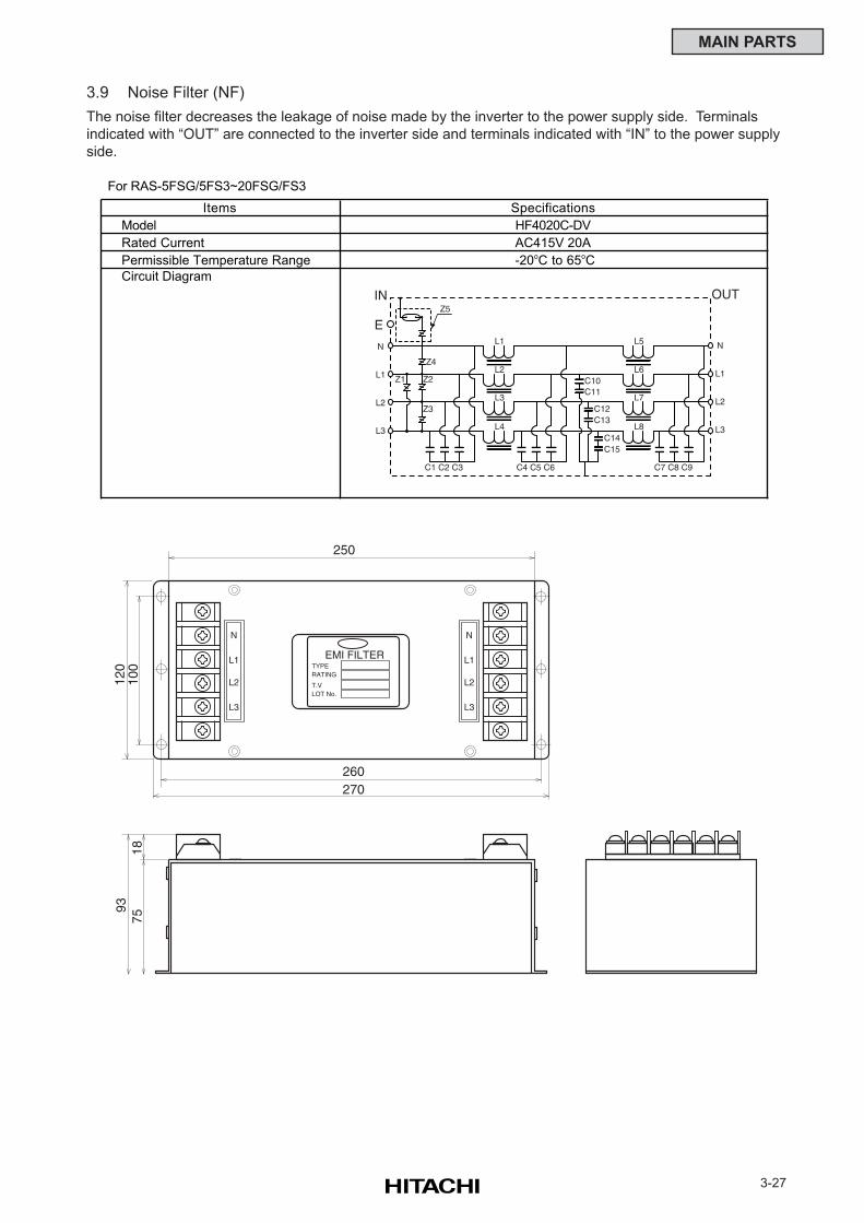
3-27
MAIN PARTS
3.9 Noise Filter (NF)
The noise filter decreases the leakage of noise made by the inverter to the power supply side. Terminals
indicated with “OUT” are connected to the inverter side and terminals indicated with “IN” to the power supply
side.
For RAS-5FSG/5FS3~20FSG/FS3
Items Specifications
Model HF4020C-DV
Rated Current AC415V 20A
Permissible Temperature Range -20oC to 65oC
Circuit Diagram
L1
C1 C2 C3 C4 C5 C6 C7 C8 C9
L2
L3
L4
L5
L6
L7
L8
C10C11
C12C13
C14C15
Z5
Z4
Z2
Z3
Z1
IN
E
N
L1
L2
L3
OUT
N
L1
L2
L3
N
L1
L2
L3
N
L1
L2
L3
EMI FILTERTYPERATING
T.VLOT No.
120
100
250
260270
9375
18
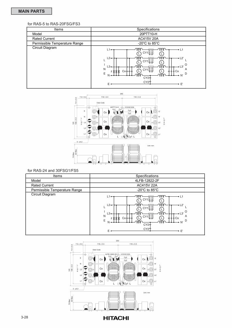
3-28
MAIN PARTS
Cx
Cx
Cx
Cx
Cx
Cx
250
7.0 ± 0.3
7.0
± 0.
310
6 ±
0.3
120
70 M
ax.
30 M
ax.
E
N
L3
L2
L1
E
N
L3
L2
L1
LINE
E'
N'
L3'
L2'
L1'
E'
N'
L3'
L2'
L1'
LOAD
Z
Z
Z
Cy2Cy1Cy1
Cy2
L LCy1
20PTT10-H 415VAC/20A
Unit: mm
118 ± 0.3118 ± 0.3
Date Code
5 - φ4.2
Cx
Cx
Cx
Cx
Cx
Cx
250
7.0 ± 0.3
7.0
± 0.
310
6 ±
0.3
120
70 M
ax.
30 M
ax.
E
N
L3
L2
L1
E
N
L3
L2
L1
LINE
E'
N'
L3'
L2'
L1'
E'
N'
L3'
L2'
L1'
LOAD
Z
Z
Z
Cy2Cy1Cy1
Cy2
L LCy1
4LFB-12822-2F 415VAC/22A
Unit: mm
118 ± 0.3118 ± 0.3
Date Code
5 - φ4.2
for RAS-5 to RAS-20FSG/FS3
for RAS-24 and 30FSG1/FS5
Items Specifications
Model 20PTT10-H
Rated Current AC415V 20A
Permissible Temperature Range -20oC to 85oC
Circuit Diagram
L
L
L
L
L
L
CY1
CY1
CY1
CY2
CY2
Cx Cxz
L1
L2
L3
N
E
L1
L2'
L3'
N'
E'
L
I
N
E
L
O
A
D
Items Specifications
Model 4LFB-12822-2F
Rated Current AC415V 22A
Permissible Temperature Range -20oC to 85oC
Circuit Diagram
L
L
L
L
L
L
CY1
CY1
CY1
CY2
CY2
Cx Cxz
L1
L2
L3
N
E
L1
L2'
L3'
N'
E'
L
I
N
E
L
O
A
D
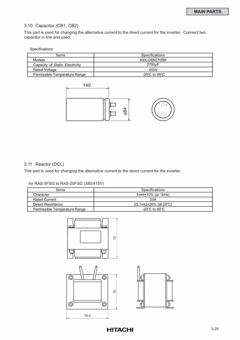
3-29
MAIN PARTS
3.10 Capacitor (CB1, CB2)
This part is used for changing the alternative current to the direct current for the inverter. Connect two
capacitor in line and used.
3.11 Reactor (DCL)
This part is used for changing the alternative current to the direct current for the inverter.
Specifications
Items Specifications
Models 400LGSN2700M
Capacity of Static Electricity 2700µF
Rated Voltage 400V
Permissible Temperature Range -25oC to 95oC
7570
76.2
140
φ84
+
−
Items Specifications
Character 1mH+10% (at 1kHz)
Rated Current 33A
Direct Resistance 25.1mΩ+20% (at 20oC)
Permissible Temperature Range -20oC to 60oC
for RAS-5FSG to RAS-20FSG (380/415V)
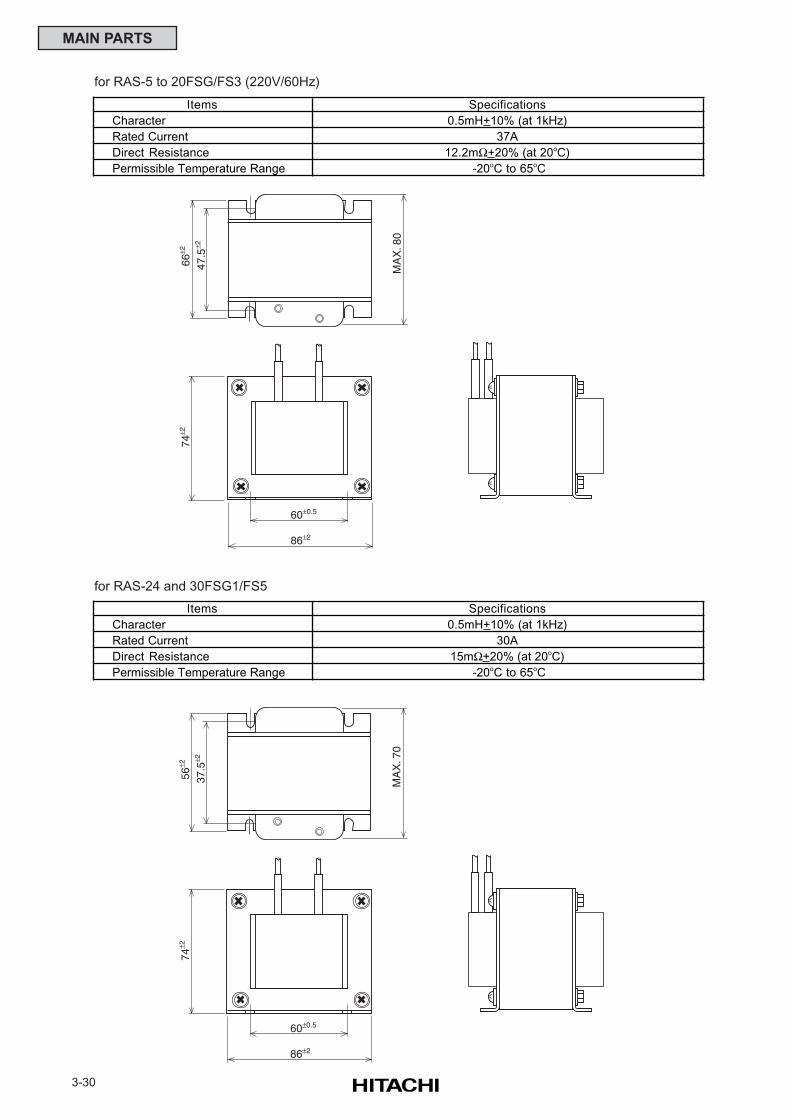
3-30
MAIN PARTS
Items Specifications
Character 0.5mH+10% (at 1kHz)
Rated Current 37A
Direct Resistance 12.2mΩ+20% (at 20oC)
Permissible Temperature Range -20oC to 65oC
66±2
74±2
86±2
60±0.5
47.5
±2
MA
X. 8
0
56±2
74±2
86±2
60±0.5
37.5
±2
MA
X. 7
0
for RAS-5 to 20FSG/FS3 (220V/60Hz)
for RAS-24 and 30FSG1/FS5
Items Specifications
Character 0.5mH+10% (at 1kHz)
Rated Current 30A
Direct Resistance 15mΩ+20% (at 20oC)
Permissible Temperature Range -20oC to 65oC
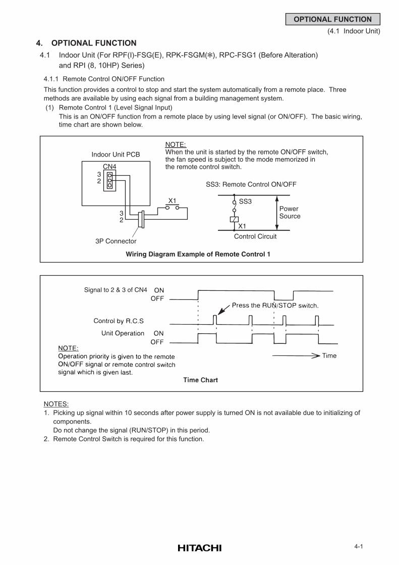
4-1
OPTIONAL FUNCTION
(4.1 Indoor Unit)
4. OPTIONAL FUNCTION
4.1 Indoor Unit (For RPF(I)-FSG(E), RPK-FSGM(), RPC-FSG1 (Before Alteration)
and RPI (8, 10HP) Series)
4.1.1 Remote Control ON/OFF Function
This function provides a control to stop and start the system automatically from a remote place. Three
methods are available by using each signal from a building management system.
(1) Remote Control 1 (Level Signal Input)
This is an ON/OFF function from a remote place by using level signal (or ON/OFF). The basic wiring,
time chart are shown below.
NOTES:
1. Picking up signal within 10 seconds after power supply is turned ON is not available due to initializing of
components.
Do not change the signal (RUN/STOP) in this period.
2. Remote Control Switch is required for this function.
SS3
X1
PowerSource
Control Circuit
Indoor Unit PCB
CN4
X1
3P Connector
3 2
3 2
NOTE:When the unit is started by the remote ON/OFF switch, the fan speed is subject to the mode memorized inthe remote control switch.
SS3: Remote Control ON/OFF
Wiring Diagram Example of Remote Control 1
Signal to 2 & 3 of CN4
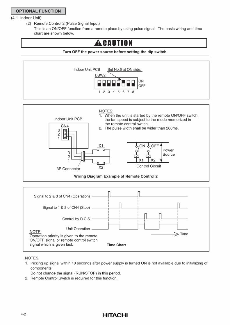
4-2
OPTIONAL FUNCTION
(4.1 Indoor Unit)
(2) Remote Control 2 (Pulse Signal Input)
This is an ON/OFF function from a remote place by using pulse signal. The basic wiring and time
chart are shown below.
Turn OFF the power source before setting the dip switch.
NOTES:
1. Picking up signal within 10 seconds after power supply is turned ON is not available due to initializing of
components.
Do not change the signal (RUN/STOP) in this period.
2. Remote Control Switch is required for this function.
1
Indoor Unit PCB Set No.6 at ON side.
ONOFF
2 3 4 5 6 7 8
DSW2
ON
X1
OFF
X2
PowerSource
Control Circuit
Indoor Unit PCB
CN4
X1
X23P Connector
3 2 1
3 2 1
NOTES:1. When the unit is started by the remote ON/OFF switch, the fan speed is subject to the mode memorized in the remote control switch.2. The pulse width shall be wider than 200ms.
Wiring Diagram Example of Remote Control 2
Signal to 2 & 3 of CN4 (Operation)
Signal to 1 & 2 of CN4 (Stop)
NOTE:Operation priority is given to the remoteON/OFF signal or remote control switchsignal which is given last.
Control by R.C.S
Unit Operation
Time Chart
Time
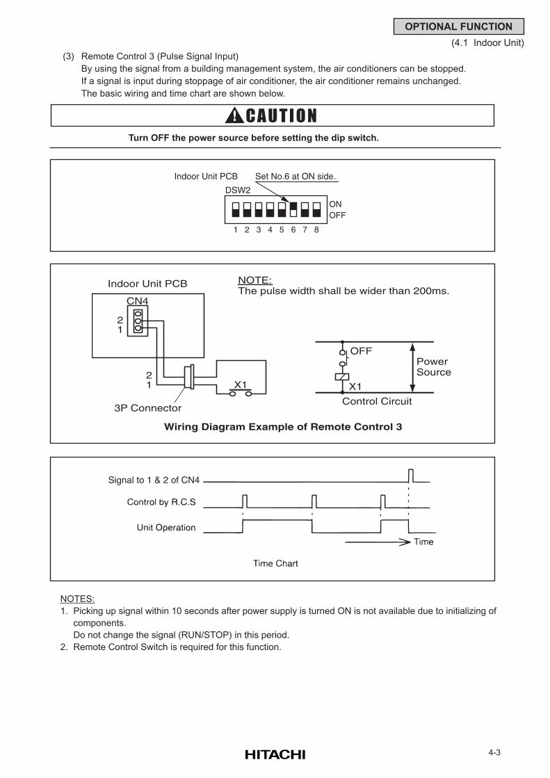
4-3
OPTIONAL FUNCTION
(4.1 Indoor Unit)
(3) Remote Control 3 (Pulse Signal Input)
By using the signal from a building management system, the air conditioners can be stopped.
If a signal is input during stoppage of air conditioner, the air conditioner remains unchanged.
The basic wiring and time chart are shown below.
Turn OFF the power source before setting the dip switch.
NOTES:
1. Picking up signal within 10 seconds after power supply is turned ON is not available due to initializing of
components.
Do not change the signal (RUN/STOP) in this period.
2. Remote Control Switch is required for this function.
OFF
X1
PowerSource
Control Circuit
Indoor Unit PCB
CN4
X1
3P Connector
2 1
2 1
NOTE:The pulse width shall be wider than 200ms.
Wiring Diagram Example of Remote Control 3
1
Indoor Unit PCB Set No.6 at ON side.
ONOFF
2 3 4 5 6 7 8
DSW2
Signal to 1 & 2 of CN4
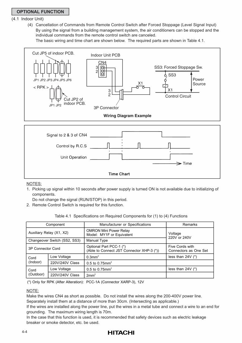
4-4
OPTIONAL FUNCTION
(4.1 Indoor Unit)
(4) Cancellation of Commands from Remote Control Switch after Forced Stoppage (Level Signal Input)
By using the signal from a building management system, the air conditioners can be stopped and the
individual commands from the remote control switch are canceled.
The basic wiring and time chart are shown below. The required parts are shown in Table 4.1.
Table 4.1 Specifications on Required Components for (1) to (4) Functions
NOTE:
Make the wires CN4 as short as possible. Do not install the wires along the 200-400V power line.
Separately install them at a distance of more than 30cm. (Intersecting as applicable.)
If the wires are installed along the power line, put the wires in a metal tube and connect a wire to an end for
grounding. The maximum wiring length is 70m.
In the case that this function is used, it is recommended that safety devices such as electric leakage
breaker or smoke detector, etc. be used.
NOTES:
1. Picking up signal within 10 seconds after power supply is turned ON is not available due to initializing of
components.
Do not change the signal (RUN/STOP) in this period.
2. Remote Control Switch is required for this function.
Cut JP5 of indoor PCB.
JP1 JP2 JP3 JP4 JP5 JP6
< RPK >
Cut JP2 of indoor PCB.
SS3
X1
PowerSource
Control Circuit
Indoor Unit PCB
CN4
X1
3P Connector
32
32
SS3: Forced Stoppage Sw.
Wiring Diagram Example
JP1 JP2
CN4
Manufacturer or Specifications Remarks
Auxiliary Relay (X1, X2) OMRON Mini Power Relay Model: MY1F or Equivalent
Changeover Switch (SS2, SS3) Manual Type
3P Connector Cord Optional Part PCC-1 (*) (Able to Connect JST Connector XHP-3 (*))
Five Cords with Connectors as One Set
Low Voltage 0.3mm2 less than 24V (*)
220V/240V Class 0.5 to 0.75mm2
Low Voltage 0.5 to 0.75mm2 less than 24V (*)
220V/240V Class 2mm2
(*) Only for RPK (After Alteration): PCC-1A (Connector XARP-3), 12V
Component
Voltage 220V or 240V
Cord (Indoor)
Cord (Outdoor)
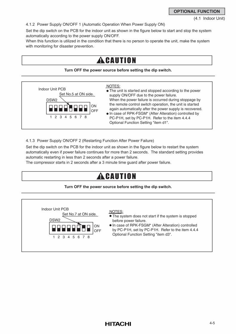
4-5
OPTIONAL FUNCTION
(4.1 Indoor Unit)
4.1.2 Power Supply ON/OFF 1 (Automatic Operation When Power Supply ON)
Set the dip switch on the PCB for the indoor unit as shown in the figure below to start and stop the system
automatically according to the power supply ON/OFF.
When this function is utilized in the condition that there is no person to operate the unit, make the system
with monitoring for disaster prevention.
Turn OFF the power source before setting the dip switch.
4.1.3 Power Supply ON/OFF 2 (Restarting Function After Power Failure)
Set the dip switch on the PCB for the indoor unit as shown in the figure below to restart the system
automatically even if power failure continues for more than 2 seconds. The standard setting provides
automatic restarting in less than 2 seconds after a power failure.
The compressor starts in 2 seconds after a 3 minute time guard after power failure.
Turn OFF the power source before setting the dip switch.
1
Indoor Unit PCBSet No.5 at ON side.
ONOFF
2 3 4 5 6 7 8
DSW2
NOTES:The unit is started and stopped according to the powersupply ON/OFF due to the power failure.When the power failure is occurred during stoppage bythe remote control switch operation, the unit is startedagain automatically after the power supply is recovered.In case of RPK-FSGM* (After Alteration) controlled byPC-P1H, set by PC-P1H. Refer to the item 4.4.4 Optional Function Setting "item d1".
1
Indoor Unit PCBSet No.7 at ON side.
ONOFF
2 3 4 5 6 7 8
DSW2
NOTES:The system does not start if the system is stoppedbefore power failure. In case of RPK-FSGM* (After Alteration) controlled by PC-P1H, set by PC-P1H. Refer to the item 4.4.4 Optional Function Setting "item d3".
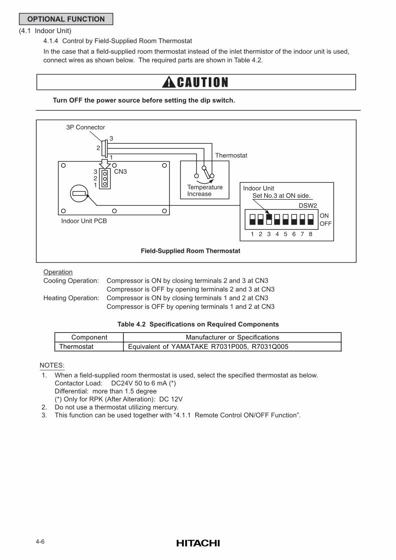
4-6
OPTIONAL FUNCTION
(4.1 Indoor Unit)
4.1.4 Control by Field-Supplied Room Thermostat
In the case that a field-supplied room thermostat instead of the inlet thermistor of the indoor unit is used,
connect wires as shown below. The required parts are shown in Table 4.2.
Turn OFF the power source before setting the dip switch.
Table 4.2 Specifications on Required Components
NOTES:
1. When a field-supplied room thermostat is used, select the specified thermostat as below.
Contactor Load: DC24V 50 to 6 mA (*)
Differential: more than 1.5 degree
(*) Only for RPK (After Alteration): DC 12V
2. Do not use a thermostat utilizing mercury.
3. This function can be used together with “4.1.1 Remote Control ON/OFF Function”.
Operation
Cooling Operation: Compressor is ON by closing terminals 2 and 3 at CN3
Compressor is OFF by opening terminals 2 and 3 at CN3
Heating Operation: Compressor is ON by closing terminals 1 and 2 at CN3
Compressor is OFF by opening terminals 1 and 2 at CN3
2
TemperatureIncrease
Thermostat
CN33 2 1
3
1
Indoor Unit PCB
3P Connector
1
Indoor UnitSet No.3 at ON side.
ONOFF
2 3 4 5 6 7 8
DSW2
Field-Supplied Room Thermostat
Component Manufacturer or Specifications
Thermostat Equivalent of YAMATAKE R7031P005, R7031Q005
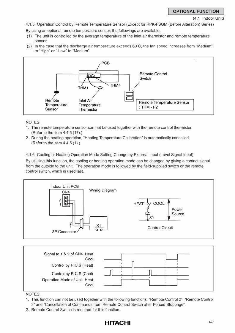
4-7
OPTIONAL FUNCTION
(4.1 Indoor Unit)
4.1.5 Operation Control by Remote Temperature Sensor (Except for RPK-FSGM (Before Alteration) Series)
By using an optional remote temperature sensor, the followings are available.
(1) The unit is controlled by the average temperature of the inlet air thermistor and remote temperature
sensor.
(2) In the case that the discharge air temperature exceeds 60oC, the fan speed increases from “Medium”
to “High” or “ Low” to “Medium”.
NOTES:
1. The remote temperature sensor can not be used together with the remote control thermistor.
(Refer to the item 4.4.5 (17).)
2. During the heating operation, “Heating Temperature Calibration” is automatically cancelled.
(Refer to the item 4.4.5 (1).)
4.1.6 Cooling or Heating Operation Mode Setting Change by External Input (Level Signal Input)
By utilizing this function, the cooling or heating operation mode can be changed by giving a contact signal
from the outside to the unit. The operation mode is followed by the field-supplied switch or the remote
control switch, which is used last.
NOTES:
1. This function can not be used together with the following functions; “Remote Control 2”, “Remote Control
3” and “Cancellation of Commands from Remote Control Switch after Forced Stoppage”.
2. Remote Control Switch is required for this function.
CN4
CN4
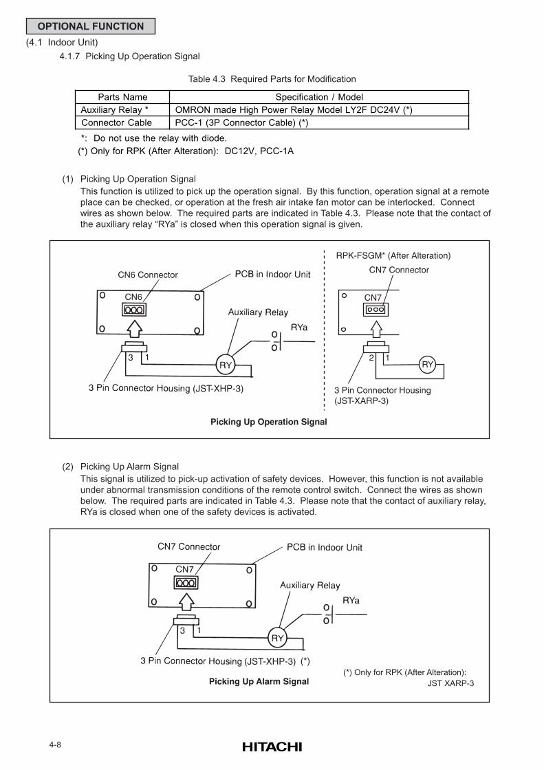
4-8
OPTIONAL FUNCTION
(4.1 Indoor Unit)
4.1.7 Picking Up Operation Signal
Table 4.3 Required Parts for Modification
(1) Picking Up Operation Signal
This function is utilized to pick up the operation signal. By this function, operation signal at a remote
place can be checked, or operation at the fresh air intake fan motor can be interlocked. Connect
wires as shown below. The required parts are indicated in Table 4.3. Please note that the contact of
the auxiliary relay “RYa” is closed when this operation signal is given.
(2) Picking Up Alarm Signal
This signal is utilized to pick-up activation of safety devices. However, this function is not available
under abnormal transmission conditions of the remote control switch. Connect the wires as shown
below. The required parts are indicated in Table 4.3. Please note that the contact of auxiliary relay,
RYa is closed when one of the safety devices is activated.
Picking Up Alarm Signal
(JST-XHP-3)
Parts Name Specification / Model
Auxiliary Relay * OMRON made High Power Relay Model LY2F DC24V (*)
Connector Cable PCC-1 (3P Connector Cable) (*)
*: Do not use the relay with diode.
(*) Only for RPK (After Alteration): DC12V, PCC-1A
(*)
(*) Only for RPK (After Alteration):
JST XARP-3
CN6 Connector
Picking Up Operation Signal
CN6
(JST-XHP-3)
RY
CN7 Connector
CN7
12
3 Pin Connector Housing(JST-XARP-3)
RPK-FSGM* (After Alteration)
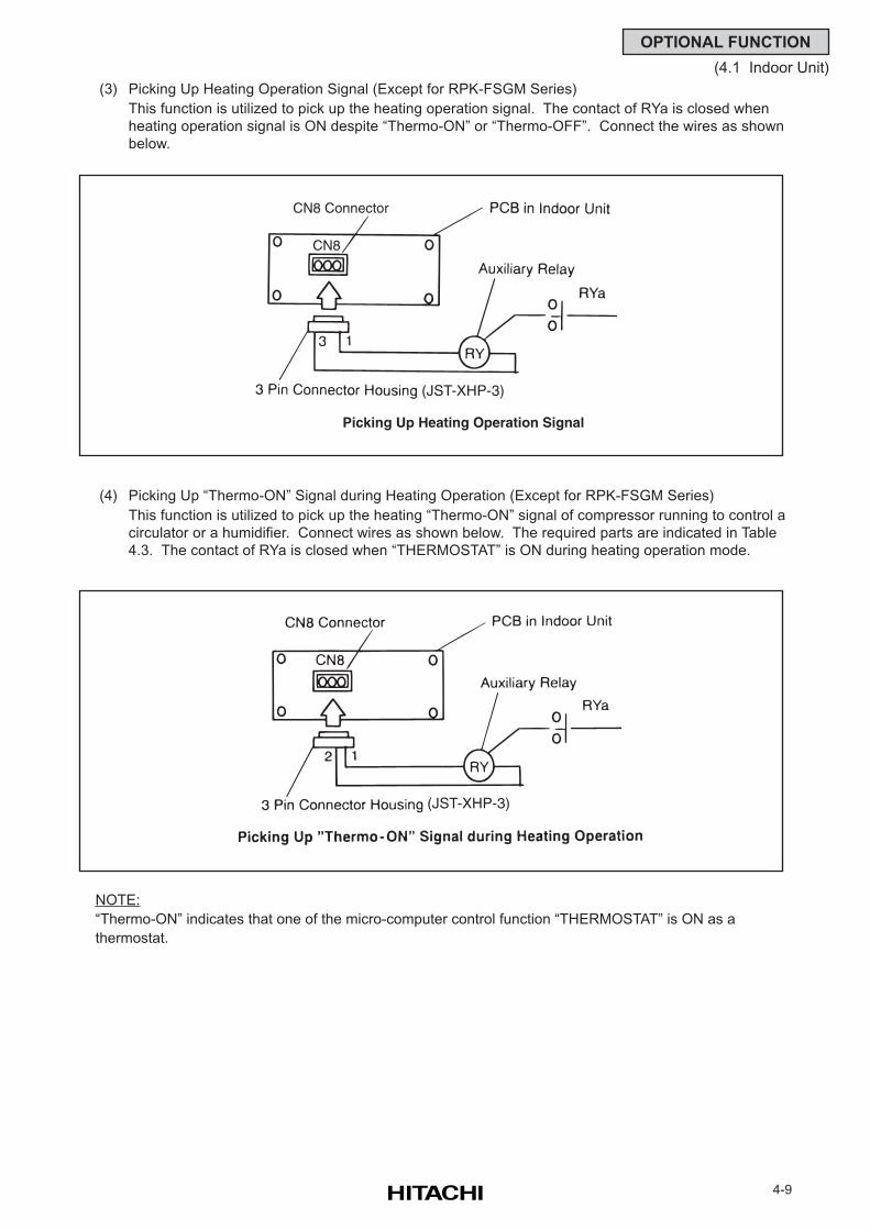
4-9
OPTIONAL FUNCTION
(4.1 Indoor Unit)
(3) Picking Up Heating Operation Signal (Except for RPK-FSGM Series)
This function is utilized to pick up the heating operation signal. The contact of RYa is closed when
heating operation signal is ON despite “Thermo-ON” or “Thermo-OFF”. Connect the wires as shown
below.
(4) Picking Up “Thermo-ON” Signal during Heating Operation (Except for RPK-FSGM Series)
This function is utilized to pick up the heating “Thermo-ON” signal of compressor running to control a
circulator or a humidifier. Connect wires as shown below. The required parts are indicated in Table
4.3. The contact of RYa is closed when “THERMOSTAT” is ON during heating operation mode.
NOTE:
“Thermo-ON” indicates that one of the micro-computer control function “THERMOSTAT” is ON as a
thermostat.
Picking Up Heating Operation Signal
CN8 Connector
CN8
(JST-XHP-3)
(JST-XHP-3)
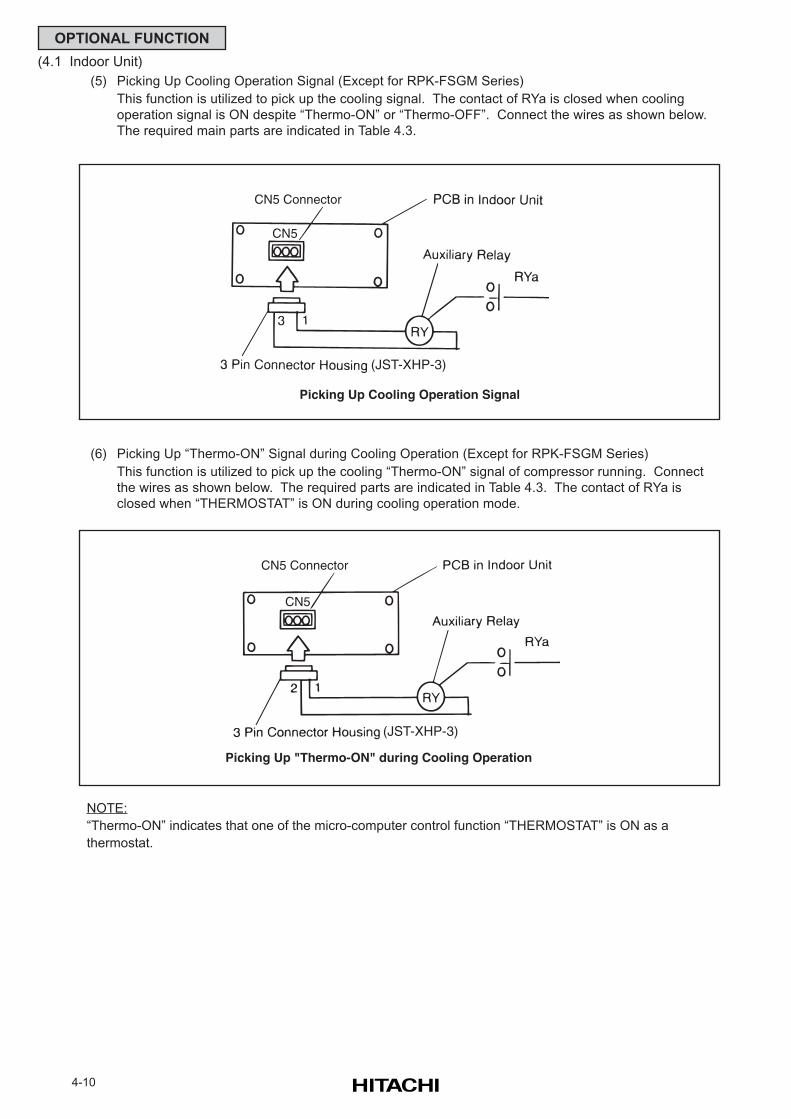
4-10
OPTIONAL FUNCTION
(4.1 Indoor Unit)
(5) Picking Up Cooling Operation Signal (Except for RPK-FSGM Series)
This function is utilized to pick up the cooling signal. The contact of RYa is closed when cooling
operation signal is ON despite “Thermo-ON” or “Thermo-OFF”. Connect the wires as shown below.
The required main parts are indicated in Table 4.3.
(6) Picking Up “Thermo-ON” Signal during Cooling Operation (Except for RPK-FSGM Series)
This function is utilized to pick up the cooling “Thermo-ON” signal of compressor running. Connect
the wires as shown below. The required parts are indicated in Table 4.3. The contact of RYa is
closed when “THERMOSTAT” is ON during cooling operation mode.
NOTE:
“Thermo-ON” indicates that one of the micro-computer control function “THERMOSTAT” is ON as a
thermostat.
Picking Up Cooling Operation Signal
CN5 Connector
CN5
(JST-XHP-3)
CN5 Connector
Picking Up "Thermo-ON" during Cooling Operation
CN5
(JST-XHP-3)
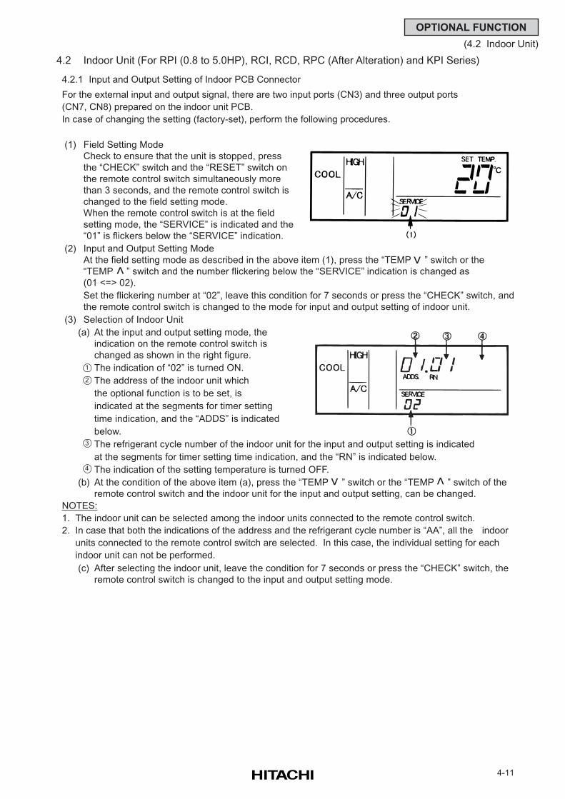
4-11
OPTIONAL FUNCTION
(4.2 Indoor Unit)
4.2 Indoor Unit (For RPI (0.8 to 5.0HP), RCI, RCD, RPC (After Alteration) and KPI Series)
4.2.1 Input and Output Setting of Indoor PCB Connector
For the external input and output signal, there are two input ports (CN3) and three output ports
(CN7, CN8) prepared on the indoor unit PCB.
In case of changing the setting (factory-set), perform the following procedures.
(1) Field Setting Mode
Check to ensure that the unit is stopped, press
the “CHECK” switch and the “RESET” switch on
the remote control switch simultaneously more
than 3 seconds, and the remote control switch is
changed to the field setting mode.
When the remote control switch is at the field
setting mode, the “SERVICE” is indicated and the
“01” is flickers below the “SERVICE” indication.
(2) Input and Output Setting Mode
At the field setting mode as described in the above item (1), press the “TEMP ” switch or the
“TEMP ” switch and the number flickering below the “SERVICE” indication is changed as
(01 <=> 02).
Set the flickering number at “02”, leave this condition for 7 seconds or press the “CHECK” switch, and
the remote control switch is changed to the mode for input and output setting of indoor unit.
(3) Selection of Indoor Unit
(a) At the input and output setting mode, the
indication on the remote control switch is
changed as shown in the right figure.
The indication of “02” is turned ON.
The address of the indoor unit which
the optional function is to be set, is
indicated at the segments for timer setting
time indication, and the “ADDS” is indicated
below.
The refrigerant cycle number of the indoor unit for the input and output setting is indicated
at the segments for timer setting time indication, and the “RN” is indicated below.
The indication of the setting temperature is turned OFF.
(b) At the condition of the above item (a), press the “TEMP ” switch or the “TEMP ” switch of the
remote control switch and the indoor unit for the input and output setting, can be changed.
NOTES:
1. The indoor unit can be selected among the indoor units connected to the remote control switch.
2. In case that both the indications of the address and the refrigerant cycle number is “AA”, all the indoor
units connected to the remote control switch are selected. In this case, the individual setting for each
indoor unit can not be performed.
(c) After selecting the indoor unit, leave the condition for 7 seconds or press the “CHECK” switch, the
remote control switch is changed to the input and output setting mode.
1
2
3
4
>
>
>
>
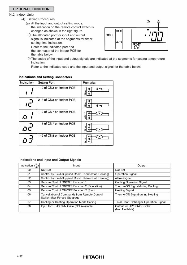
4-12
OPTIONAL FUNCTION
(4.2 Indoor Unit)
(4) Setting Procedures
(a) At the input and output setting mode,
the indication on the remote control switch is
changed as shown in the right figure.
The allocated port for input and output
signal is indicated at the segments for timer
setting time indication.
Refer to the indicated port and
the connector of the indoor PCB for
the table below.
The codes of the input and output signals are indicated at the segments for setting temperature
indication.
Refer to the indicated code and the input and output signal for the table below.
Indications and Input and Output Signals
1
2
Indication 2 Input Output
00 Not Set Not Set
01 Control by Field-Supplied Room Thermostat (Cooling) Operation Signal
02 Control by Field-Supplied Room Thermostat (Heating) Alarm Signal
03 Remote Control ON/OFF Function 1 Cooling Operation Signal
04 Remote Control ON/OFF Function 2 (Operation) Thermo-ON Signal during Cooling
05 Remote Control ON/OFF Function 2 (Stop) Heating Signal
06 Cancellation of Commands from Remote Control Switch after Forced Stoppage
Thermo-ON Signal during Heating
07 Cooling or Heating Operation Mode Setting Total Heat Exchanger Operation Signal
08 Input for UP/DOWN Grille (Not Available) Output for UP/DOWN Grille (Not Available)
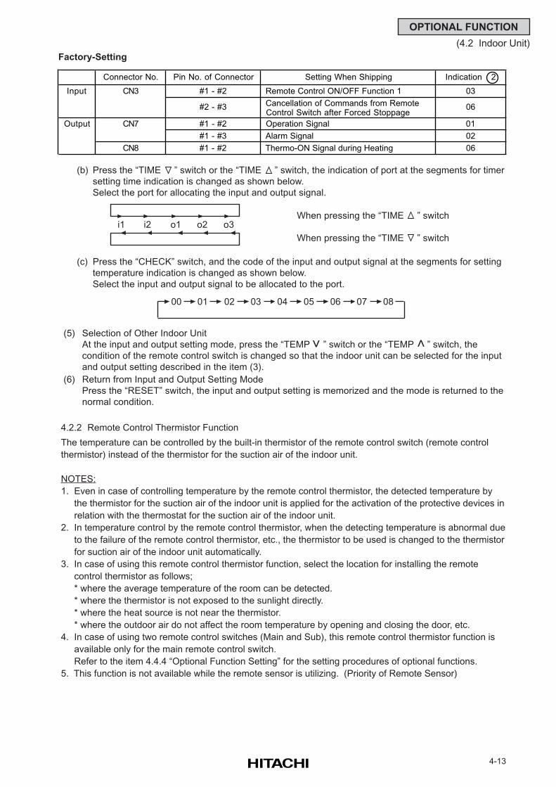
4-13
OPTIONAL FUNCTION
(4.2 Indoor Unit)
Factory-Setting
(b) Press the “TIME ” switch or the “TIME ” switch, the indication of port at the segments for timer
setting time indication is changed as shown below.
Select the port for allocating the input and output signal.
When pressing the “TIME ” switch
When pressing the “TIME ” switch
(c) Press the “CHECK” switch, and the code of the input and output signal at the segments for setting
temperature indication is changed as shown below.
Select the input and output signal to be allocated to the port.
(5) Selection of Other Indoor Unit
At the input and output setting mode, press the “TEMP ” switch or the “TEMP ” switch, the
condition of the remote control switch is changed so that the indoor unit can be selected for the input
and output setting described in the item (3).
(6) Return from Input and Output Setting Mode
Press the “RESET” switch, the input and output setting is memorized and the mode is returned to the
normal condition.
4.2.2 Remote Control Thermistor Function
The temperature can be controlled by the built-in thermistor of the remote control switch (remote control
thermistor) instead of the thermistor for the suction air of the indoor unit.
NOTES:
1. Even in case of controlling temperature by the remote control thermistor, the detected temperature by
the thermistor for the suction air of the indoor unit is applied for the activation of the protective devices in
relation with the thermostat for the suction air of the indoor unit.
2. In temperature control by the remote control thermistor, when the detecting temperature is abnormal due
to the failure of the remote control thermistor, etc., the thermistor to be used is changed to the thermistor
for suction air of the indoor unit automatically.
3. In case of using this remote control thermistor function, select the location for installing the remote
control thermistor as follows;
* where the average temperature of the room can be detected.
* where the thermistor is not exposed to the sunlight directly.
* where the heat source is not near the thermistor.
* where the outdoor air do not affect the room temperature by opening and closing the door, etc.
4. In case of using two remote control switches (Main and Sub), this remote control thermistor function is
available only for the main remote control switch.
Refer to the item 4.4.4 “Optional Function Setting” for the setting procedures of optional functions.
5. This function is not available while the remote sensor is utilizing. (Priority of Remote Sensor)
>
>
i1 i2 o1 o2 o3
00 01 02 03 04 05 06 07 08
Connector No. Pin No. of Connector Setting When Shipping Indication 2
Input CN3 #1 - #2 Remote Control ON/OFF Function 1 03
#2 - #3 Cancellation of Commands from Remote Control Switch after Forced Stoppage
06
Output CN7 #1 - #2 Operation Signal 01
#1 - #3 Alarm Signal 02
CN8 #1 - #2 Thermo-ON Signal during Heating 06
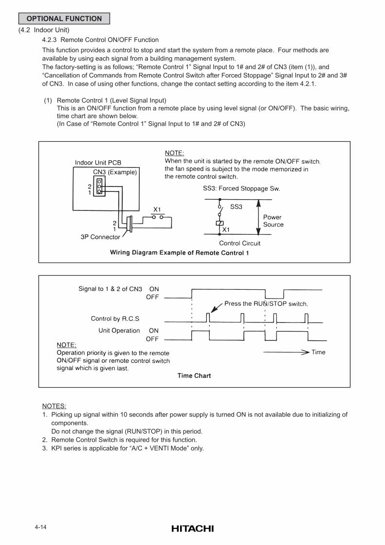
4-14
OPTIONAL FUNCTION
(4.2 Indoor Unit)
4.2.3 Remote Control ON/OFF Function
This function provides a control to stop and start the system from a remote place. Four methods are
available by using each signal from a building management system.
The factory-setting is as follows; “Remote Control 1” Signal Input to 1# and 2# of CN3 (item (1)), and
“Cancellation of Commands from Remote Control Switch after Forced Stoppage” Signal Input to 2# and 3#
of CN3. In case of using other functions, change the contact setting according to the item 4.2.1.
(1) Remote Control 1 (Level Signal Input)
This is an ON/OFF function from a remote place by using level signal (or ON/OFF). The basic wiring,
time chart are shown below.
(In Case of “Remote Control 1” Signal Input to 1# and 2# of CN3)
NOTES:
1. Picking up signal within 10 seconds after power supply is turned ON is not available due to initializing of
components.
Do not change the signal (RUN/STOP) in this period.
2. Remote Control Switch is required for this function.
3. KPI series is applicable for “A/C + VENTI Mode” only.
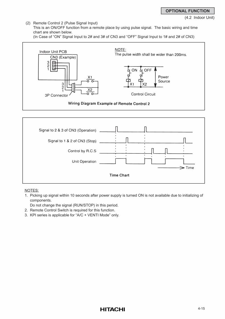
4-15
OPTIONAL FUNCTION
(4.2 Indoor Unit)
(2) Remote Control 2 (Pulse Signal Input)
This is an ON/OFF function from a remote place by using pulse signal. The basic wiring and time
chart are shown below.
(In Case of “ON” Signal Input to 2# and 3# of CN3 and “OFF” Signal Input to 1# and 2# of CN3)
NOTES:
1. Picking up signal within 10 seconds after power supply is turned ON is not available due to initializing of
components.
Do not change the signal (RUN/STOP) in this period.
2. Remote Control Switch is required for this function.
3. KPI series is applicable for “A/C + VENTI Mode” only.
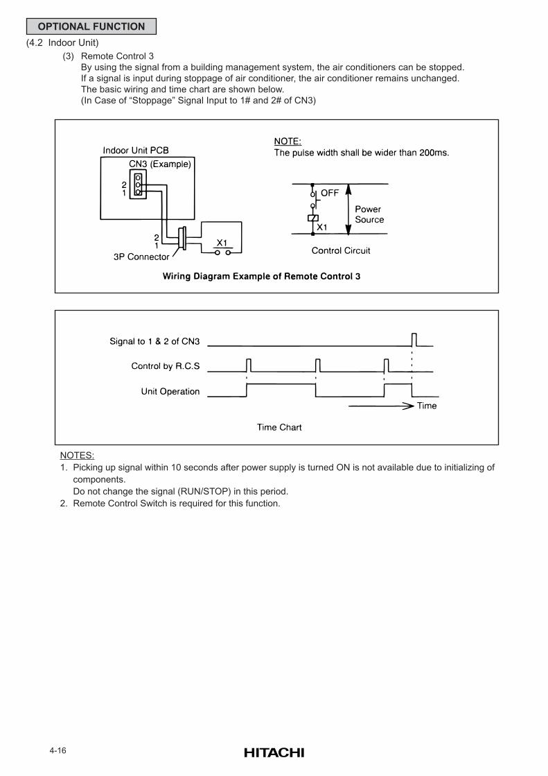
4-16
OPTIONAL FUNCTION
(4.2 Indoor Unit)
(3) Remote Control 3
By using the signal from a building management system, the air conditioners can be stopped.
If a signal is input during stoppage of air conditioner, the air conditioner remains unchanged.
The basic wiring and time chart are shown below.
(In Case of “Stoppage” Signal Input to 1# and 2# of CN3)
NOTES:
1. Picking up signal within 10 seconds after power supply is turned ON is not available due to initializing of
components.
Do not change the signal (RUN/STOP) in this period.
2. Remote Control Switch is required for this function.
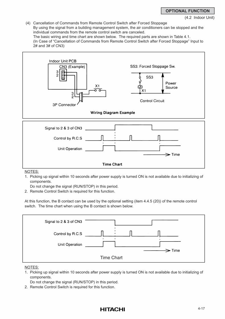
4-17
OPTIONAL FUNCTION
(4.2 Indoor Unit)
(4) Cancellation of Commands from Remote Control Switch after Forced Stoppage
By using the signal from a building management system, the air conditioners can be stopped and the
individual commands from the remote control switch are canceled.
The basic wiring and time chart are shown below. The required parts are shown in Table 4.1.
(In Case of “Cancellation of Commands from Remote Control Switch after Forced Stoppage” Input to
2# and 3# of CN3)
At this function, the B contact can be used by the optional setting (item 4.4.5 (20)) of the remote control
switch. The time chart when using the B contact is shown below.
Time Chart
NOTES:
1. Picking up signal within 10 seconds after power supply is turned ON is not available due to initializing of
components.
Do not change the signal (RUN/STOP) in this period.
2. Remote Control Switch is required for this function.
NOTES:
1. Picking up signal within 10 seconds after power supply is turned ON is not available due to initializing of
components.
Do not change the signal (RUN/STOP) in this period.
2. Remote Control Switch is required for this function.
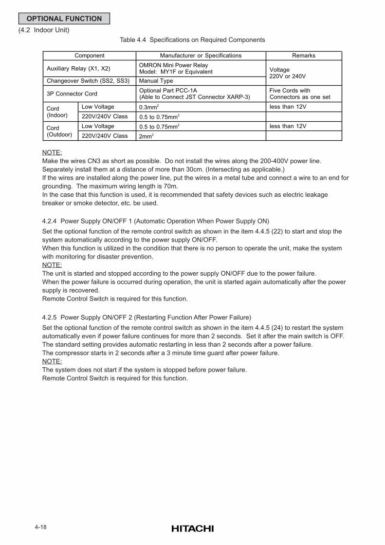
4-18
OPTIONAL FUNCTION
(4.2 Indoor Unit)
Table 4.4 Specifications on Required Components
NOTE:
Make the wires CN3 as short as possible. Do not install the wires along the 200-400V power line.
Separately install them at a distance of more than 30cm. (Intersecting as applicable.)
If the wires are installed along the power line, put the wires in a metal tube and connect a wire to an end for
grounding. The maximum wiring length is 70m.
In the case that this function is used, it is recommended that safety devices such as electric leakage
breaker or smoke detector, etc. be used.
4.2.4 Power Supply ON/OFF 1 (Automatic Operation When Power Supply ON)
Set the optional function of the remote control switch as shown in the item 4.4.5 (22) to start and stop the
system automatically according to the power supply ON/OFF.
When this function is utilized in the condition that there is no person to operate the unit, make the system
with monitoring for disaster prevention.
NOTE:
The unit is started and stopped according to the power supply ON/OFF due to the power failure.
When the power failure is occurred during operation, the unit is started again automatically after the power
supply is recovered.
Remote Control Switch is required for this function.
4.2.5 Power Supply ON/OFF 2 (Restarting Function After Power Failure)
Set the optional function of the remote control switch as shown in the item 4.4.5 (24) to restart the system
automatically even if power failure continues for more than 2 seconds. Set it after the main switch is OFF.
The standard setting provides automatic restarting in less than 2 seconds after a power failure.
The compressor starts in 2 seconds after a 3 minute time guard after power failure.
NOTE:
The system does not start if the system is stopped before power failure.
Remote Control Switch is required for this function.
Manufacturer or Specifications Remarks
Auxiliary Relay (X1, X2) OMRON Mini Power Relay Model: MY1F or Equivalent
Changeover Switch (SS2, SS3) Manual Type
3P Connector Cord Optional Part PCC-1A (Able to Connect JST Connector XARP-3)
Five Cords with Connectors as one set
Low Voltage 0.3mm2 less than 12V
220V/240V Class 0.5 to 0.75mm2
Low Voltage 0.5 to 0.75mm2 less than 12V
220V/240V Class 2mm2
Component
Voltage 220V or 240V
Cord (Indoor)
Cord (Outdoor)
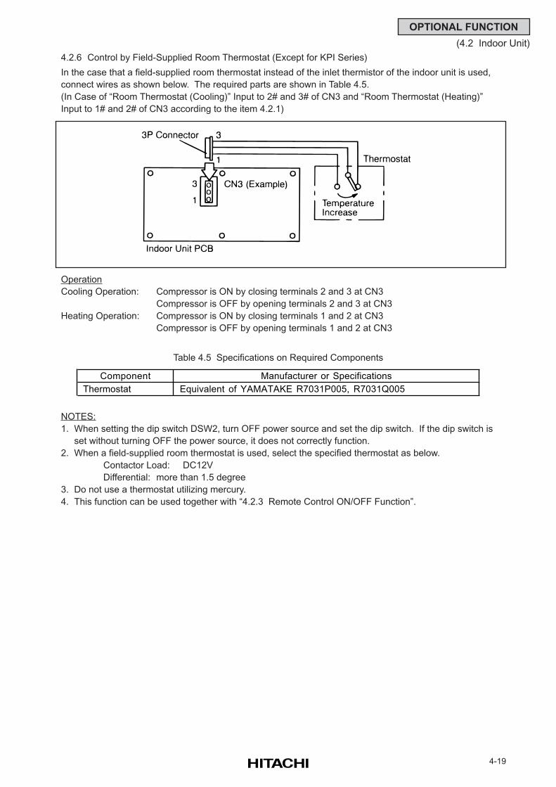
4-19
OPTIONAL FUNCTION
(4.2 Indoor Unit)
4.2.6 Control by Field-Supplied Room Thermostat (Except for KPI Series)
In the case that a field-supplied room thermostat instead of the inlet thermistor of the indoor unit is used,
connect wires as shown below. The required parts are shown in Table 4.5.
(In Case of “Room Thermostat (Cooling)” Input to 2# and 3# of CN3 and “Room Thermostat (Heating)”
Input to 1# and 2# of CN3 according to the item 4.2.1)
Operation
Cooling Operation: Compressor is ON by closing terminals 2 and 3 at CN3
Compressor is OFF by opening terminals 2 and 3 at CN3
Heating Operation: Compressor is ON by closing terminals 1 and 2 at CN3
Compressor is OFF by opening terminals 1 and 2 at CN3
Table 4.5 Specifications on Required Components
NOTES:
1. When setting the dip switch DSW2, turn OFF power source and set the dip switch. If the dip switch is
set without turning OFF the power source, it does not correctly function.
2. When a field-supplied room thermostat is used, select the specified thermostat as below.
Contactor Load: DC12V
Differential: more than 1.5 degree
3. Do not use a thermostat utilizing mercury.
4. This function can be used together with “4.2.3 Remote Control ON/OFF Function”.
Component Manufacturer or Specifications
Thermostat Equivalent of YAMATAKE R7031P005, R7031Q005
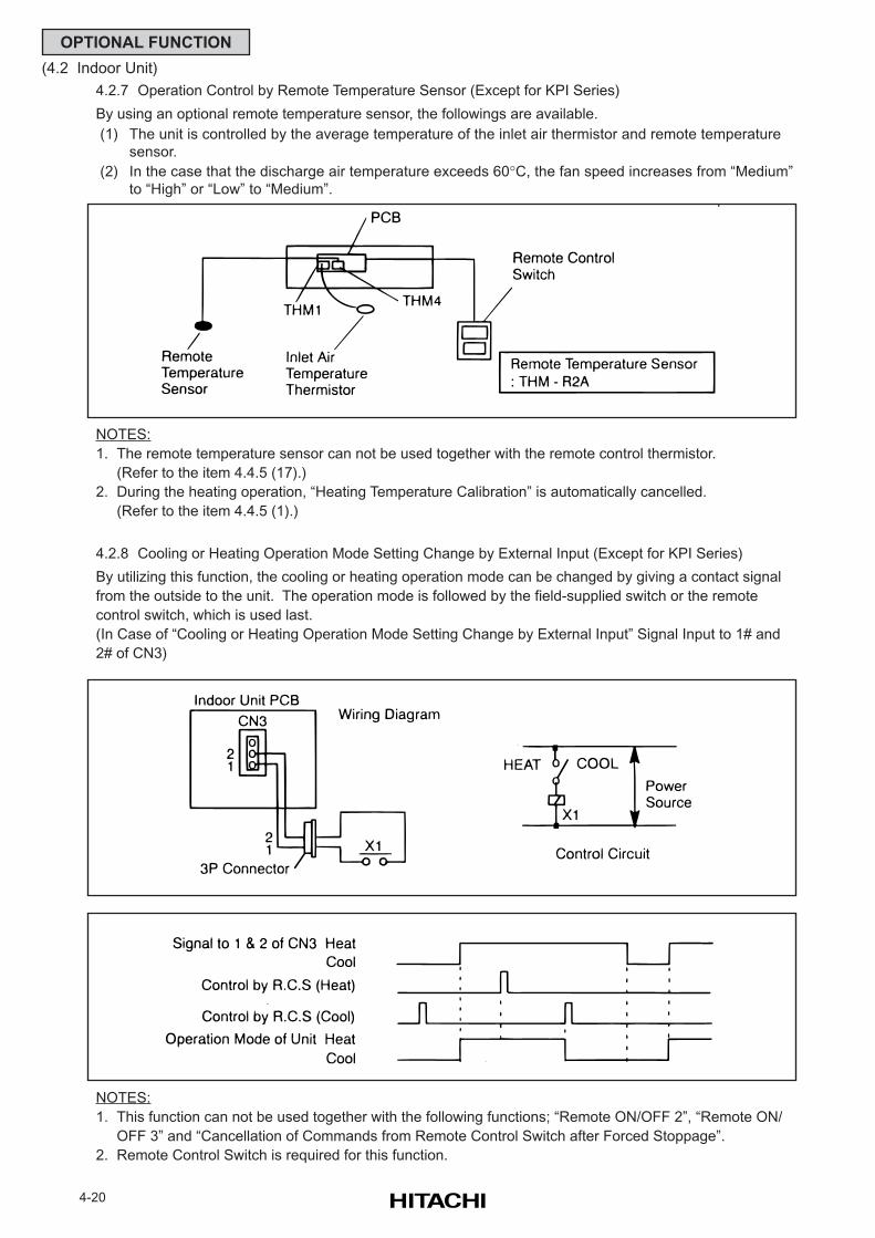
4-20
OPTIONAL FUNCTION
(4.2 Indoor Unit)
4.2.7 Operation Control by Remote Temperature Sensor (Except for KPI Series)
By using an optional remote temperature sensor, the followings are available.
(1) The unit is controlled by the average temperature of the inlet air thermistor and remote temperature
sensor.
(2) In the case that the discharge air temperature exceeds 60°C, the fan speed increases from “Medium”
to “High” or “Low” to “Medium”.
NOTES:
1. The remote temperature sensor can not be used together with the remote control thermistor.
(Refer to the item 4.4.5 (17).)
2. During the heating operation, “Heating Temperature Calibration” is automatically cancelled.
(Refer to the item 4.4.5 (1).)
4.2.8 Cooling or Heating Operation Mode Setting Change by External Input (Except for KPI Series)
By utilizing this function, the cooling or heating operation mode can be changed by giving a contact signal
from the outside to the unit. The operation mode is followed by the field-supplied switch or the remote
control switch, which is used last.
(In Case of “Cooling or Heating Operation Mode Setting Change by External Input” Signal Input to 1# and
2# of CN3)
NOTES:
1. This function can not be used together with the following functions; “Remote ON/OFF 2”, “Remote ON/
OFF 3” and “Cancellation of Commands from Remote Control Switch after Forced Stoppage”.
2. Remote Control Switch is required for this function.
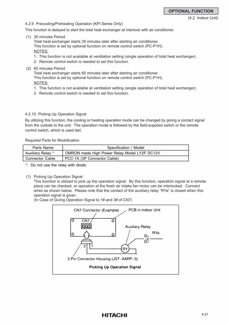
4-21
OPTIONAL FUNCTION
(4.2 Indoor Unit)
4.2.9 Precooling/Preheating Operation (KPI Series Only)
This function is delayed to start the total heat exchanger at interlock with air conditioner.
(1) 30 minutes Period
Total heat exchanger starts 30 minutes later after starting air conditioner.
This function is set by optional function on remote control switch (PC-P1H).
NOTES:
1. This function is not available at ventilation setting (single operation of total heat exchanger).
2. Remote control switch is needed to set this function.
(2) 60 minutes Period
Total heat exchanger starts 60 minutes later after starting air conditioner.
This function is set by optional function on remote control switch (PC-P1H).
NOTES:
1. This function is not available at ventilation setting (single operation of total heat exchanger).
2. Remote control switch is needed to set this function.
4.2.10 Picking Up Operation Signal
By utilizing this function, the cooling or heating operation mode can be changed by giving a contact signal
from the outside to the unit. The operation mode is followed by the field-supplied switch or the remote
control switch, which is used last.
Required Parts for Modofication
(1) Picking Up Operation Signal
This function is utilized to pick up the operation signal. By this function, operation signal at a remote
place can be checked, or operation at the fresh air intake fan motor can be interlocked. Connect
wires as shown below. Please note that the contact of the auxiliary relay “RYa” is closed when this
operation signal is given.
(In Case of Giving Operation Signal to 1# and 3# of CN7)
Parts Name Specification / Model
Auxiliary Relay * OMRON made High Power Relay Model LY2F DC12V
Connector Cable PCC-1A (3P Connector Cable)
*: Do not use the relay with diode.
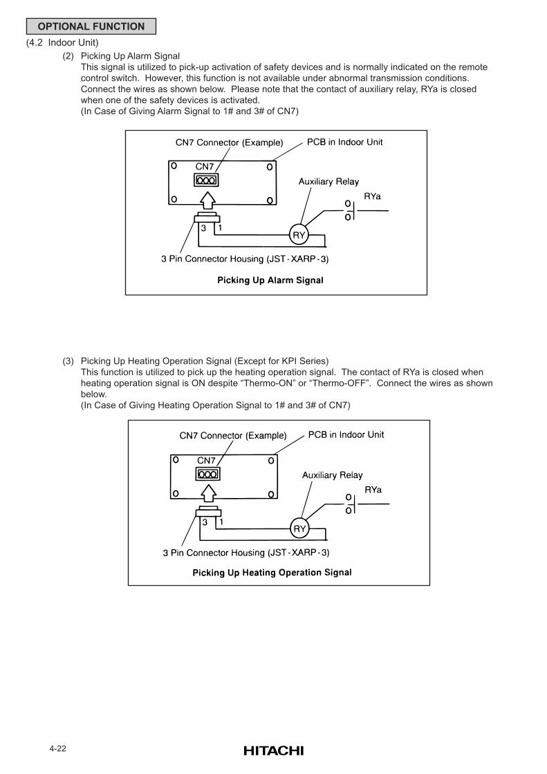
4-22
OPTIONAL FUNCTION
(4.2 Indoor Unit)
(3) Picking Up Heating Operation Signal (Except for KPI Series)
This function is utilized to pick up the heating operation signal. The contact of RYa is closed when
heating operation signal is ON despite “Thermo-ON” or “Thermo-OFF”. Connect the wires as shown
below.
(In Case of Giving Heating Operation Signal to 1# and 3# of CN7)
(2) Picking Up Alarm Signal
This signal is utilized to pick-up activation of safety devices and is normally indicated on the remote
control switch. However, this function is not available under abnormal transmission conditions.
Connect the wires as shown below. Please note that the contact of auxiliary relay, RYa is closed
when one of the safety devices is activated.
(In Case of Giving Alarm Signal to 1# and 3# of CN7)
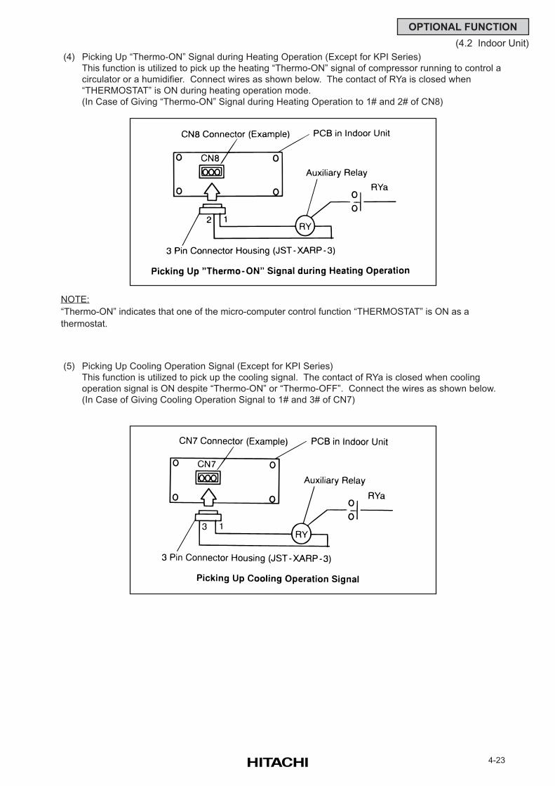
4-23
OPTIONAL FUNCTION
(4.2 Indoor Unit)
(4) Picking Up “Thermo-ON” Signal during Heating Operation (Except for KPI Series)
This function is utilized to pick up the heating “Thermo-ON” signal of compressor running to control a
circulator or a humidifier. Connect wires as shown below. The contact of RYa is closed when
“THERMOSTAT” is ON during heating operation mode.
(In Case of Giving “Thermo-ON” Signal during Heating Operation to 1# and 2# of CN8)
NOTE:
“Thermo-ON” indicates that one of the micro-computer control function “THERMOSTAT” is ON as a
thermostat.
(5) Picking Up Cooling Operation Signal (Except for KPI Series)
This function is utilized to pick up the cooling signal. The contact of RYa is closed when cooling
operation signal is ON despite “Thermo-ON” or “Thermo-OFF”. Connect the wires as shown below.
(In Case of Giving Cooling Operation Signal to 1# and 3# of CN7)
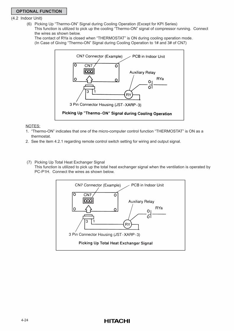
4-24
OPTIONAL FUNCTION
(4.2 Indoor Unit)
(7) Picking Up Total Heat Exchanger Signal
This function is utilized to pick up the total heat exchanger signal when the ventilation is operated by
PC-P1H. Connect the wires as shown below.
(6) Picking Up “Thermo-ON” Signal during Cooling Operation (Except for KPI Series)
This function is utilized to pick up the cooling “Thermo-ON” signal of compressor running. Connect
the wires as shown below.
The contact of RYa is closed when “THERMOSTAT” is ON during cooling operation mode.
(In Case of Giving “Thermo-ON” Signal during Cooling Operation to 1# and 3# of CN7)
NOTES:
1. “Thermo-ON” indicates that one of the micro-computer control function “THERMOSTAT” is ON as a
thermostat.
2. See the item 4.2.1 regarding remote control switch setting for wiring and output signal.
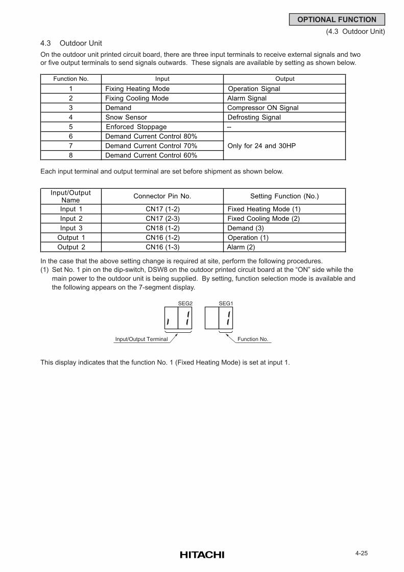
4-25
OPTIONAL FUNCTION
(4.3 Outdoor Unit)
4.3 Outdoor Unit
On the outdoor unit printed circuit board, there are three input terminals to receive external signals and two
or five output terminals to send signals outwards. These signals are available by setting as shown below.
Each input terminal and output terminal are set before shipment as shown below.
In the case that the above setting change is required at site, perform the following procedures.
(1) Set No. 1 pin on the dip-switch, DSW8 on the outdoor printed circuit board at the “ON” side while the
main power to the outdoor unit is being supplied. By setting, function selection mode is available and
the following appears on the 7-segment display.
This display indicates that the function No. 1 (Fixed Heating Mode) is set at input 1.
SEG2
Input/Output Terminal
SEG1
Function No.
Function No. Input Output
1 Fixing Heating Mode Operation Signal
2 Fixing Cooling Mode Alarm Signal
3 Demand Compressor ON Signal
4 Snow Sensor Defrosting Signal
5 Enforced Stoppage --
6 Demand Current Control 80%
7 Demand Current Control 70%
8 Demand Current Control 60%
Input/OutputName
Connector Pin No. Setting Function (No.)
Input 1 CN17 (1-2) Fixed Heating Mode (1)
Input 2 CN17 (2-3) Fixed Cooling Mode (2)
Input 3 CN18 (1-2) Demand (3)
Output 1 CN16 (1-2) Operation (1)
Output 2 CN16 (1-3) Alarm (2)
Only for 24 and 30HP
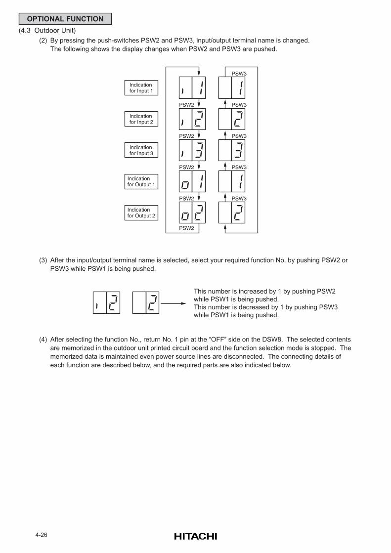
4-26
OPTIONAL FUNCTION
(4.3 Outdoor Unit)
(2) By pressing the push-switches PSW2 and PSW3, input/output terminal name is changed.
The following shows the display changes when PSW2 and PSW3 are pushed.
(3) After the input/output terminal name is selected, select your required function No. by pushing PSW2 or
PSW3 while PSW1 is being pushed.
(4) After selecting the function No., return No. 1 pin at the “OFF” side on the DSW8. The selected contents
are memorized in the outdoor unit printed circuit board and the function selection mode is stopped. The
memorized data is maintained even power source lines are disconnected. The connecting details of
each function are described below, and the required parts are also indicated below.
PSW2
Indicationfor Input 1
PSW3
PSW3
PSW2
PSW2
PSW2
PSW2
PSW3
PSW3
PSW3
Indicationfor Input 2
Indicationfor Input 3
Indicationfor Output 1
Indicationfor Output 2
This number is increased by 1 by pushing PSW2
while PSW1 is being pushed.
This number is decreased by 1 by pushing PSW3
while PSW1 is being pushed.
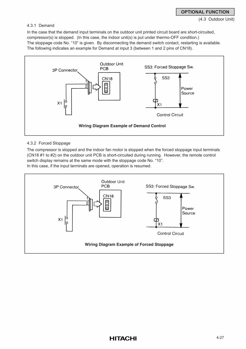
4-27
OPTIONAL FUNCTION
(4.3 Outdoor Unit)
4.3.1 Demand
In the case that the demand input terminals on the outdoor unit printed circuit board are short-circuited,
compressor(s) is stopped. (In this case, the indoor unit(s) is put under thermo-OFF condition.)
The stoppage code No. “10” is given. By disconnecting the demand switch contact, restarting is available.
The following indicates an example for Demand at input 3 (between 1 and 2 pins of CN18).
4.3.2 Forced Stoppage
The compressor is stopped and the indoor fan motor is stopped when the forced stoppage input terminals
(CN18 #1 to #2) on the outdoor unit PCB is short-circuited during running. However, the remote control
switch display remains at the same mode with the stoppage code No. “10”.
In this case, if the input terminals are opened, operation is resumed.
Wiring Diagram Example of Demand Control
Wiring Diagram Example of Forced Stoppage
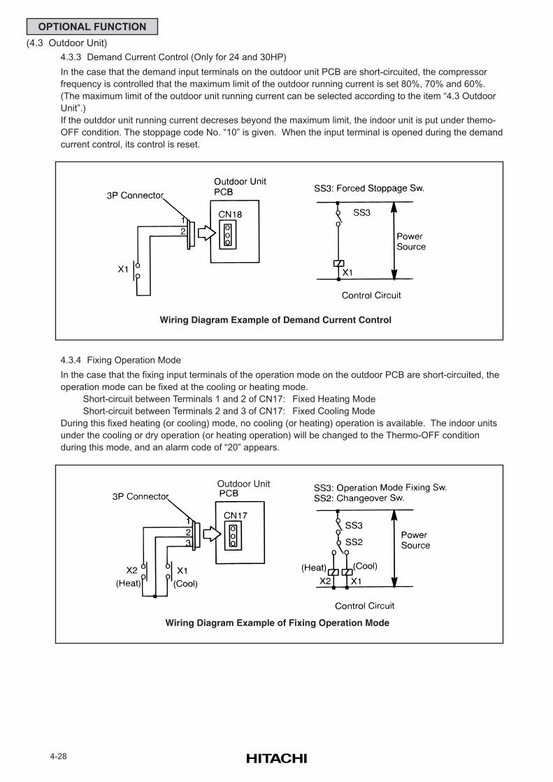
4-28
OPTIONAL FUNCTION
(4.3 Outdoor Unit)
4.3.4 Fixing Operation Mode
In the case that the fixing input terminals of the operation mode on the outdoor PCB are short-circuited, the
operation mode can be fixed at the cooling or heating mode.
Short-circuit between Terminals 1 and 2 of CN17: Fixed Heating Mode
Short-circuit between Terminals 2 and 3 of CN17: Fixed Cooling Mode
During this fixed heating (or cooling) mode, no cooling (or heating) operation is available. The indoor units
under the cooling or dry operation (or heating operation) will be changed to the Thermo-OFF condition
during this mode, and an alarm code of “20” appears.
Wiring Diagram Example of Fixing Operation Mode
Outdoor Unit
4.3.3 Demand Current Control (Only for 24 and 30HP)
In the case that the demand input terminals on the outdoor unit PCB are short-circuited, the compressor
frequency is controlled that the maximum limit of the outdoor running current is set 80%, 70% and 60%.
(The maximum limit of the outdoor unit running current can be selected according to the item “4.3 Outdoor
Unit”.)
If the outddor unit running current decreses beyond the maximum limit, the indoor unit is put under themo-
OFF condition. The stoppage code No. “10” is given. When the input terminal is opened during the demand
current control, its control is reset.
Wiring Diagram Example of Demand Current Control
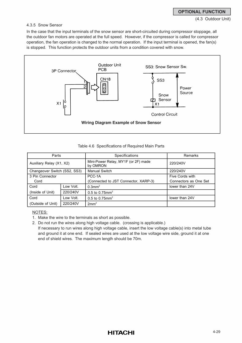
4-29
OPTIONAL FUNCTION
(4.3 Outdoor Unit)
4.3.5 Snow Sensor
In the case that the input terminals of the snow sensor are short-circuited during compressor stoppage, all
the outdoor fan motors are operated at the full speed. However, if the compressor is called for compressor
operation, the fan operation is changed to the normal operation. If the input terminal is opened, the fan(s)
is stopped. This function protects the outdoor units from a condition covered with snow.
Wiring Diagram Example of Snow Sensor
Table 4.6 Specifications of Required Main Parts
NOTES:
1. Make the wire to the terminals as short as possible.
2. Do not run the wires along high voltage cable. (crossing is applicable.)
If necessary to run wires along high voltage cable, insert the low voltage cable(s) into metal tube
and ground it at one end. If sealed wires are used at the low voltage wire side, ground it at one
end of shield wires. The maximum length should be 70m.
Specifications Remarks
Auxiliary Relay (X1, X2) Mini-Power Relay, MY1F (or 2F) made by OMRON
220/240V
Changeover Switch (SS2, SS3) Manual Switch 220/240V
3 Pin Connector PCC-1A Five Cords with
Cord (Connected to JST Connector, XARP-3) Connectors as One Set
Cord Low Volt. 0.3mm2 lower than 24V
(Inside of Unit) 220/240V 0.5 to 0.75mm2
Cord Low Volt. 0.5 to 0.75mm2 lower than 24V
(Outside of Unit) 220/240V 2mm2
Parts
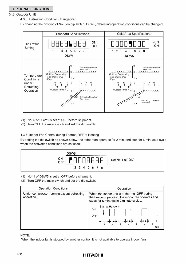
4-30
OPTIONAL FUNCTION
(4.3 Outdoor Unit)
4.3.7 Indoor Fan Control during Thermo-OFF at Heating
By setting the dip switch as shown below, the indoor fan operates for 2 min. and stop for 6 min. as a cycle
when the activation conditions are satisfied.
(1) No. 1 of DSW5 is set at OFF before shipment.
(2) Turn OFF the main switch and set the dip switch.
(1) No. 5 of DSW5 is set at OFF before shipment.
(2) Turn OFF the main switch and set the dip switch.
10
5
0
15
-8.7 -10
-10 -5
-15
-15
-4
Defrosting OperationStop Area
Defrosting OperationStart Area
Outdoor Temp.
Outdoor EvaporatingTemperature(Pipe)
56 10 15
10
5
0
15
-7
-10
-10 -5
-15
-15
-4
Defrosting OperationStop Area
Defrosting OperationStart Area
Outdoor Temp.
Outdoor EvaporatingTemperature(Pipe)
56 10 15
Dip Switch Setting
TemperatureConditionsunderDefrostingOperation
Standard Specifications Cold Area Specifications
4.3.6 Defrosting Condition Changeover
By changing the position of No.5 on dip switch, DSW5, defrosting operation conditions can be changed.
NOTE:
When the indoor fan is stopped by another control, it is not available to operate indoor fans.
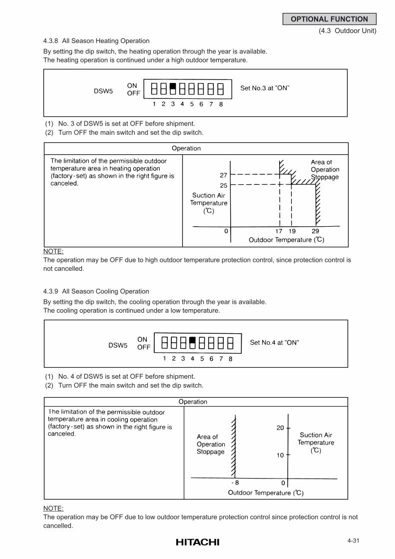
4-31
OPTIONAL FUNCTION
(4.3 Outdoor Unit)
4.3.8 All Season Heating Operation
By setting the dip switch, the heating operation through the year is available.
The heating operation is continued under a high outdoor temperature.
(1) No. 3 of DSW5 is set at OFF before shipment.
(2) Turn OFF the main switch and set the dip switch.
NOTE:
The operation may be OFF due to high outdoor temperature protection control, since protection control is
not cancelled.
4.3.9 All Season Cooling Operation
By setting the dip switch, the cooling operation through the year is available.
The cooling operation is continued under a low temperature.
(1) No. 4 of DSW5 is set at OFF before shipment.
(2) Turn OFF the main switch and set the dip switch.
NOTE:
The operation may be OFF due to low outdoor temperature protection control since protection control is not
cancelled.
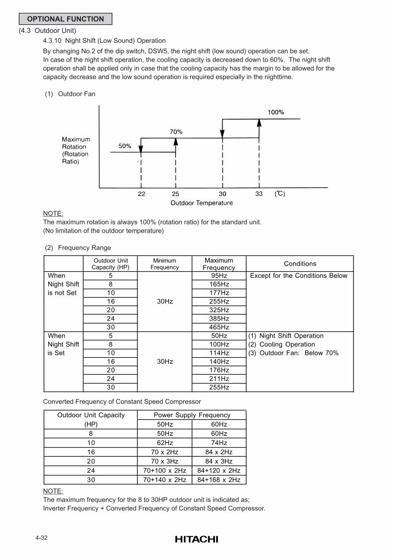
4-32
OPTIONAL FUNCTION
(4.3 Outdoor Unit)
4.3.10 Night Shift (Low Sound) Operation
By changing No.2 of the dip switch, DSW5, the night shift (low sound) operation can be set.
In case of the night shift operation, the cooling capacity is decreased down to 60%. The night shift
operation shall be applied only in case that the cooling capacity has the margin to be allowed for the
capacity decrease and the low sound operation is required especially in the nighttime.
(1) Outdoor Fan
NOTE:
The maximum rotation is always 100% (rotation ratio) for the standard unit.
(No limitation of the outdoor temperature)
(2) Frequency Range
Converted Frequency of Constant Speed Compressor
NOTE:
The maximum frequency for the 8 to 30HP outdoor unit is indicated as;
Inverter Frequency + Converted Frequency of Constant Speed Compressor.
Outdoor UnitCapacity (HP)
MinimumFrequency
MaximumFrequency
When 5 95Hz Except for the Conditions Below
Night Shift 8 165Hz
is not Set 10 177Hz
16 255Hz
20 325Hz
24 385Hz
30 465Hz
When 5 50Hz (1) Night Shift Operation
Night Shift 8 100Hz (2) Cooling Operation
is Set 10 114Hz (3) Outdoor Fan: Below 70%
16 140Hz
20 176Hz
24 211Hz
30 255Hz
50Hz 60Hz
50Hz 60Hz
62Hz 74Hz
70 x 2Hz 84 x 2Hz
70 x 3Hz 84 x 3Hz
70+100 x 2Hz 84+120 x 2Hz
70+140 x 2Hz 84+168 x 2Hz
24
30
30Hz
30Hz
16
20
Conditions
8
Power Supply Frequency
10
Outdoor Unit Capacity
(HP)
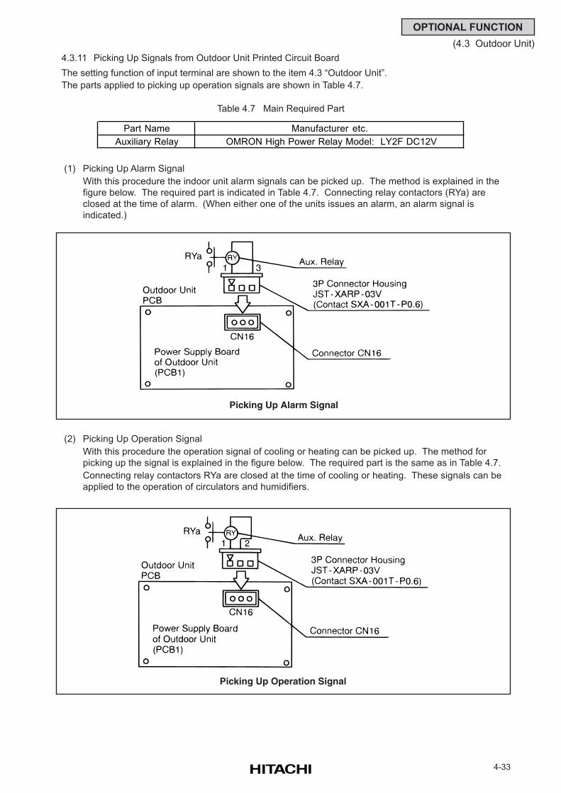
4-33
OPTIONAL FUNCTION
(4.3 Outdoor Unit)
4.3.11 Picking Up Signals from Outdoor Unit Printed Circuit Board
The setting function of input terminal are shown to the item 4.3 “Outdoor Unit”.
The parts applied to picking up operation signals are shown in Table 4.7.
Table 4.7 Main Required Part
(1) Picking Up Alarm Signal
With this procedure the indoor unit alarm signals can be picked up. The method is explained in the
figure below. The required part is indicated in Table 4.7. Connecting relay contactors (RYa) are
closed at the time of alarm. (When either one of the units issues an alarm, an alarm signal is
indicated.)
(2) Picking Up Operation Signal
With this procedure the operation signal of cooling or heating can be picked up. The method for
picking up the signal is explained in the figure below. The required part is the same as in Table 4.7.
Connecting relay contactors RYa are closed at the time of cooling or heating. These signals can be
applied to the operation of circulators and humidifiers.
Picking Up Alarm Signal
Picking Up Operation Signal
Part Name Manufacturer etc.
Auxiliary Relay OMRON High Power Relay Model: LY2F DC12V
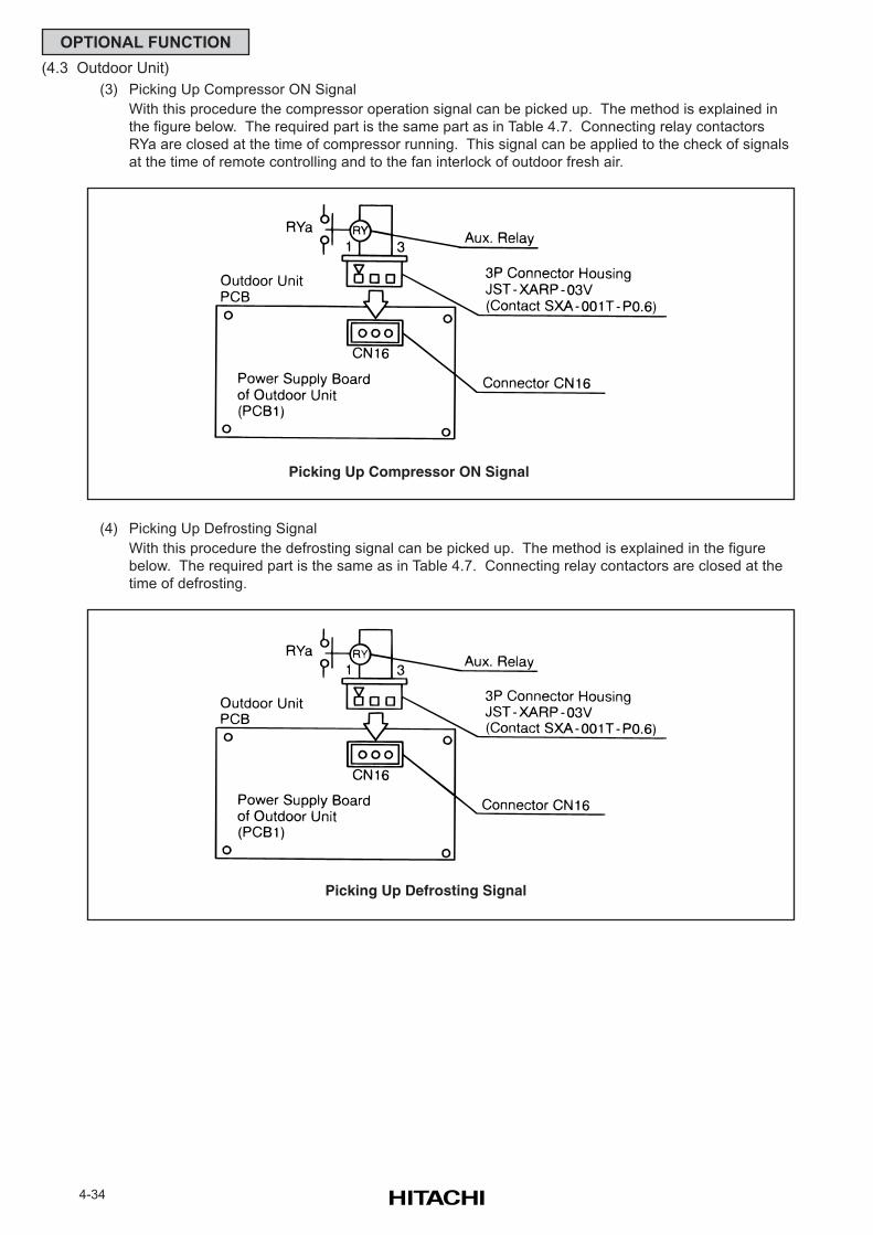
4-34
OPTIONAL FUNCTION
(4.3 Outdoor Unit)
(3) Picking Up Compressor ON Signal
With this procedure the compressor operation signal can be picked up. The method is explained in
the figure below. The required part is the same part as in Table 4.7. Connecting relay contactors
RYa are closed at the time of compressor running. This signal can be applied to the check of signals
at the time of remote controlling and to the fan interlock of outdoor fresh air.
(4) Picking Up Defrosting Signal
With this procedure the defrosting signal can be picked up. The method is explained in the figure
below. The required part is the same as in Table 4.7. Connecting relay contactors are closed at the
time of defrosting.
Picking Up Compressor ON Signal
Picking Up Defrosting Signal
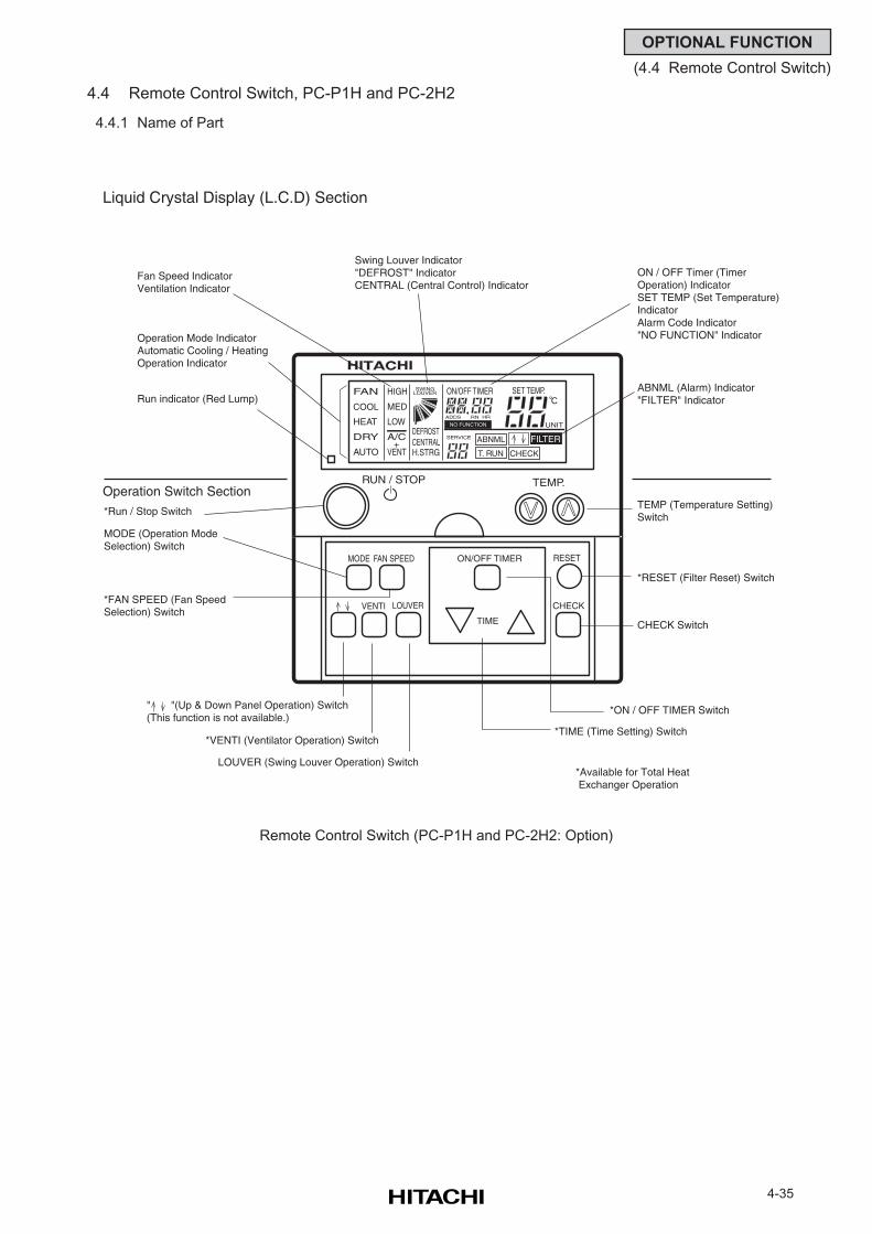
4-35
OPTIONAL FUNCTION
(4.4 Remote Control Switch)
4.4 Remote Control Switch, PC-P1H and PC-2H2
4.4.1 Name of Part
Remote Control Switch (PC-P1H and PC-2H2: Option)
TEMP.RUN / STOP
MODE FAN SPEED
VENTI
RESET
CHECKLOUVER
ON/OFF TIMER
TIME
NO FUNCTION
FAN
COOL
HEAT
DRY
AUTO
HIGH
MED
LOW
A/C
VENT+
SWING
DEFROSTCENTRALH.STRG
SERVICE
ON/OFF TIMER SET TEMP.
RN HR
FILTER
T. RUN
ABNML
CHECK
ADDS
UNIT
LOUVER
Liquid Crystal Display (L.C.D) Section
Swing Louver Indicator"DEFROST" IndicatorCENTRAL (Central Control) Indicator
Fan Speed IndicatorVentilation Indicator
Operation Mode IndicatorAutomatic Cooling / HeatingOperation Indicator
Run indicator (Red Lump)
Operation Switch Section
*Run / Stop Switch
MODE (Operation Mode Selection) Switch
*FAN SPEED (Fan Speed Selection) Switch
" "(Up & Down Panel Operation) Switch(This function is not available.)
LOUVER (Swing Louver Operation) Switch
*VENTI (Ventilator Operation) Switch*TIME (Time Setting) Switch
*ON / OFF TIMER Switch
CHECK Switch
*RESET (Filter Reset) Switch
TEMP (Temperature Setting)Switch
ABNML (Alarm) Indicator"FILTER" Indicator
ON / OFF Timer (Timer Operation) IndicatorSET TEMP (Set Temperature)IndicatorAlarm Code Indicator"NO FUNCTION" Indicator
*Available for Total Heat Exchanger Operation
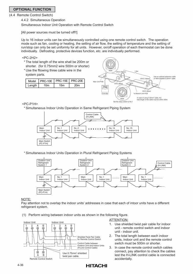
4-36
OPTIONAL FUNCTION
(4.4 Remote Control Switch)
4.4.2 Simultaneous Operation
Simultaneous Indoor Unit Operation with Remote Control Switch
[All power sources must be turned off!!]
Up to 16 indoor units can be simultaneously controlled using one remote control switch. The operationmode such as fan, cooling or heating, the setting of air flow, the setting of temperature and the setting ofrun/stop can only be set uniformly for all units. However, on/off operation of each thermostat can be doneindividually. Defrosting, protective devices function, etc. are individually performed.
NOTE:Pay attention not to overlap the indoor units’ addresses in case that each of intoor units have a differentrefrigerant system.
(1) Perform wiring between indoor units as shown in the following figure.
ATTENTION:
1. Use shielded twist pair cable for indoorunit - remote control switch and indoorunit - indoor unit.
2. The total length between each indoorunits, indoor unit and the remote controlswitch must be 500m or shorter.
3. In case the remote control switch cablesconnect, pay attention to check the cableslest the H-LINK control cable is connectedaccidentally.
Model PRC-10E PRC-15E PRC-20E
Length 10m 15m 20m
<PC-P1H>
* Simultaneous Indoor Units Operation in Same Refrigerant Piping System
Main Switch(PC-P1H)
MainIndoor Unit
No. 1Indoor Unit
Outdoor UnitRefrigerantSystem 1
MainIndoor Unit
No. 1Indoor Unit
MainIndoor Unit
No. 1Indoor Unit
Control Cable (H-LINK)
Outdoor UnitRefrigerantSystem 2
Outdoor UnitRefrigerantSystem 3
* Simultaneous Indoor Units Operation in Plural Refrigerant Piping Systems
Main Switch(PC-P1H)
MainIndoor Unit
No. 1Indoor Unit
No. 2Indoor Unit
No. 14Indoor Unit
No. 15Indoor Unit
Control Cable (H-LINK)
Indoor Unit1 2 A B
Remote Control Switch
A B
Indoor Unit1 2 A B
Use 0.75mm2 shielded twist pair cable.
Shielded Twist Pair Cablefor Remote Control Switch
Control Cable betweenOutdoor Unit and Indoor Units(H-Link Control Cable)
<PC-2H2>
* The total length of the wire shall be 200m or
shorter. (for 0.75mm2 wire 500m or shorter)
* Use the fllowing three cable wire in the
system parts.
TEMP.RUN / STOP
NO FUNCTION
FAN
COOL
HEAT
DRY
AUTO
HIGH
LOW
A/C
VENT+
SWING
DEFROSTCENTRALH.STRG
SERVICE
ON/OFF TIMER SET TEMP.
RN HR
FILTER
T. RUN
ABNML
CHECK
ADDS
UNIT
LOUVER
Controller
Main Unit PCBCN13 (Blue)
CN12 (Yellow)
CN13 (Blue)
CN12 (Yellow)
01 2
34
5
67
8
9ABC
E F
D
RSW
RSW
01 2
34
5
67
8
9ABC
E F
D
Set the rotary switch to No.1
1st Branch Unit PCB
1 Set
Use an optional extension cableor field-supplied 0.32mm2 cable.
In case of using 0.32mm2 cable, the total length of the cable must be within 200m.
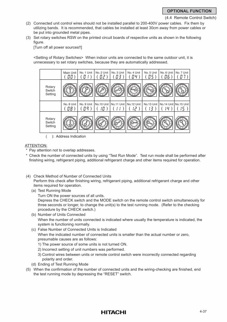
4-37
OPTIONAL FUNCTION
(4.4 Remote Control Switch)
ATTENTION:
* Pay attention not to overlap addresses.
* Check the number of connected units by using “Test Run Mode”. Test run mode shall be performed after
finishing wiring, refrigerant piping, additional refrigerant charge and other items required for operation.
(4) Check Method of Number of Connected Units
Perform this check after finishing wiring, refrigerant piping, additional refrigerant charge and other
items required for operation.
(a) Test Running Mode
Turn ON the power sources of all units.
Depress the CHECK switch and the MODE switch on the remote control switch simultaneously for
three seconds or longer, to change the unit(s) to the test running mode. (Refer to the checking
procedure by the CHECK switch.)
(b) Number of Units Connected
When the number of units connected is indicated where usually the temperature is indicated, the
system is functioning normally.
(c) False Number of Connected Units is Indicated
When the indicated number of connected units is smaller than the actual number or zero,
presumable causes are as follows:
1) The power source of some units is not turned ON.
2) Incorrect setting of unit numbers was performed.
3) Control wires between units or remote control switch were incorrectly connected regarding
polarity and order.
(d) Ending of Test Running Mode
(5) When the confirmation of the number of connected units and the wiring-checking are finished, end
the test running mode by depressing the “RESET” switch.
(2) Connected unit control wires should not be installed parallel to 200-400V power cables. Fix them by
utilizing bands. It is recommended, that cables be installed at least 30cm away from power cables or
be put into grounded metal pipes.
(3) Set rotary switches RSW on the printed circuit boards of respective units as shown in the following
figure.
[Turn off all power sources!!]
<Setting of Rotary Switches> When indoor units are connected to the same outdoor unit, it is
unnecessary to set rotary switches, because they are automatically addressed.
RotarySwitchSetting
RotarySwitchSetting
( ): Address Indication
Main Unit No. 1 Unit No. 2 Unit No. 3 Unit No. 4 Unit No. 5 Unit No. 6 Unit No. 7 Unit
No. 8 Unit No. 9 Unit No.10 Unit No.11 Unit No.12 Unit No.13 Unit No.14 Unit No.15 Unit
01 2
34
5
67
8
9ABC
E F
D
01 2
34
5
67
8
9ABC
E F
D
01 2
34
5
67
8
9ABC
E F
D
01 2
34
5
67
8
9ABC
E F
D
01 23
45
67
8
9ABC
E F
D
01 2
34
5
67
8
9ABC
E F
D
01 2
34
5
67
8
9ABC
E F
D
01 2
34
5
67
8
9ABC
E F
D
01 2
34
5
67
8
9ABC
E F
D
01 2
34
5
67
8
9ABC
E F
D
01 23
45
67
8
9ABC
E F
D
01 2
34
5
67
8
9ABC
E F
D
01 2
34
5
67
8
9ABC
E F
D
01 2
34
5
67
8
9ABC
E F
D
01 2
34
5
67
8
9ABC
E F
D
01 2
34
5
67
8
9ABC
E F
D
( ) ( ) ( ) ( ) ( ) ( ) ( ) ( )
( ) ( ) ( ) ( ) ( ) ( ) ( ) ( )
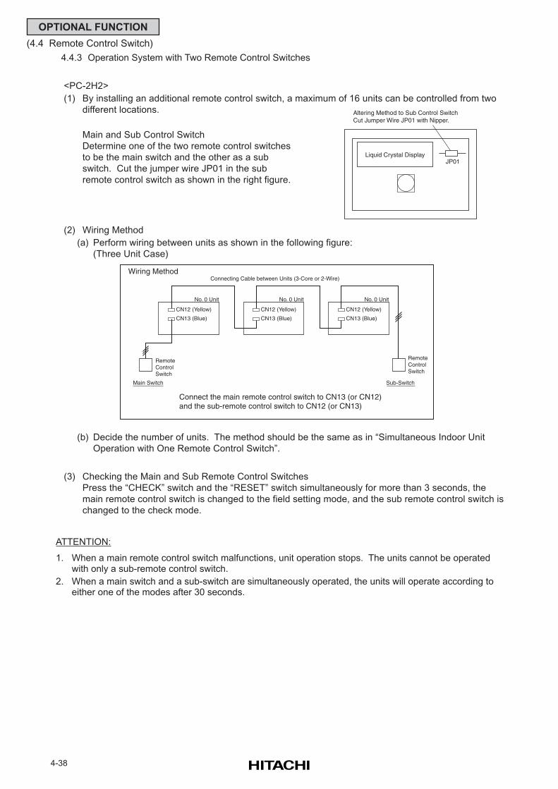
4-38
OPTIONAL FUNCTION
(4.4 Remote Control Switch)
4.4.3 Operation System with Two Remote Control Switches
<PC-2H2>
(1) By installing an additional remote control switch, a maximum of 16 units can be controlled from two
different locations.
Main and Sub Control Switch
Determine one of the two remote control switches
to be the main switch and the other as a sub
switch. Cut the jumper wire JP01 in the sub
remote control switch as shown in the right figure.
(2) Wiring Method
(a) Perform wiring between units as shown in the following figure:
(Three Unit Case)
(b) Decide the number of units. The method should be the same as in “Simultaneous Indoor Unit
Operation with One Remote Control Switch”.
(3) Checking the Main and Sub Remote Control Switches
Press the “CHECK” switch and the “RESET” switch simultaneously for more than 3 seconds, the
main remote control switch is changed to the field setting mode, and the sub remote control switch is
changed to the check mode.
Liquid Crystal DisplayJP01
Altering Method to Sub Control SwitchCut Jumper Wire JP01 with Nipper.
CN12 (Yellow)
CN13 (Blue)
No. 0 Unit
CN12 (Yellow)
CN13 (Blue)
No. 0 Unit
CN12 (Yellow)
CN13 (Blue)
No. 0 Unit
RemoteControlSwitch
RemoteControlSwitch
Sub-SwitchMain Switch
Connecting Cable between Units (3-Core or 2-Wire)
Connect the main remote control switch to CN13 (or CN12)and the sub-remote control switch to CN12 (or CN13)
Wiring Method
ATTENTION:
1. When a main remote control switch malfunctions, unit operation stops. The units cannot be operatedwith only a sub-remote control switch.
2. When a main switch and a sub-switch are simultaneously operated, the units will operate according toeither one of the modes after 30 seconds.
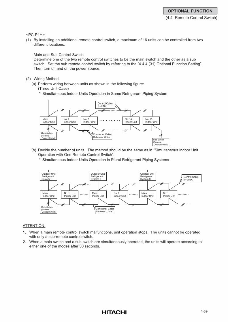
4-39
OPTIONAL FUNCTION
(4.4 Remote Control Switch)
<PC-P1H>
(1) By installing an additional remote control switch, a maximum of 16 units can be controlled from two
different locations.
Main and Sub Control Switch
Determine one of the two remote control switches to be the main switch and the other as a sub
switch. Set the sub remote control switch by referring to the “4.4.4 (31) Optional Function Setting”.
Then turn off and on the power source.
(2) Wiring Method
(a) Perform wiring between units as shown in the following figure:
(Three Unit Case)
* Simultaneous Indoor Units Operation in Same Refrigerant Piping System
(b) Decide the number of units. The method should be the same as in “Simultaneous Indoor Unit
Operation with One Remote Control Switch”.
* Simultaneous Indoor Units Operation in Plural Refrigerant Piping Systems
Connector CableBetween Units
Main Switch(Remote Control Switch)
MainIndoor Unit
No. 1Indoor Unit
Outdoor UnitRefrigerantSystem 1
MainIndoor Unit
No. 1Indoor Unit
MainIndoor Unit
No. 1Indoor Unit
Control Cable (H-LINK)
Outdoor UnitRefrigerantSystem 2
Outdoor UnitRefrigerantSystem 3
Connector CableBetween Units
Main Switch(Remote Control Switch)
Sub Switch(Remote Control Switch)
Control Cable (H-LINK)
MainIndoor Unit
No. 1Indoor Unit
No. 2Indoor Unit
No. 14Indoor Unit
No. 15Indoor Unit
ATTENTION:
1. When a main remote control switch malfunctions, unit operation stops. The units cannot be operatedwith only a sub-remote control switch.
2. When a main switch and a sub-switch are simultaneously operated, the units will operate according toeither one of the modes after 30 seconds.
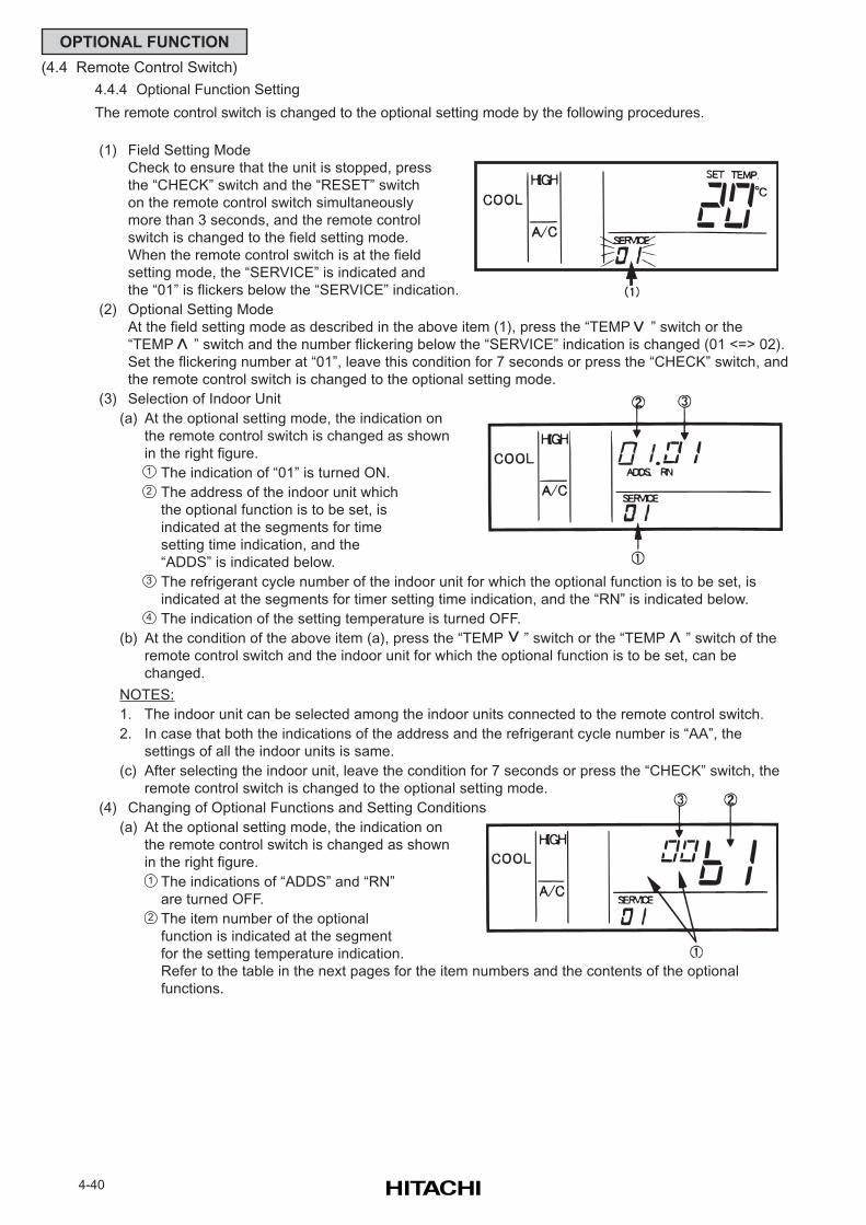
4-40
OPTIONAL FUNCTION
(4.4 Remote Control Switch)
4.4.4 Optional Function Setting
The remote control switch is changed to the optional setting mode by the following procedures.
(1) Field Setting Mode
Check to ensure that the unit is stopped, press
the “CHECK” switch and the “RESET” switch
on the remote control switch simultaneously
more than 3 seconds, and the remote control
switch is changed to the field setting mode.
When the remote control switch is at the field
setting mode, the “SERVICE” is indicated and
the “01” is flickers below the “SERVICE” indication.
(2) Optional Setting Mode
At the field setting mode as described in the above item (1), press the “TEMP ” switch or the
“TEMP ” switch and the number flickering below the “SERVICE” indication is changed (01 <=> 02).
Set the flickering number at “01”, leave this condition for 7 seconds or press the “CHECK” switch, and
the remote control switch is changed to the optional setting mode.
(3) Selection of Indoor Unit
(a) At the optional setting mode, the indication on
the remote control switch is changed as shown
in the right figure.
The indication of “01” is turned ON.
The address of the indoor unit which
the optional function is to be set, is
indicated at the segments for time
setting time indication, and the
“ADDS” is indicated below.
The refrigerant cycle number of the indoor unit for which the optional function is to be set, is
indicated at the segments for timer setting time indication, and the “RN” is indicated below.
The indication of the setting temperature is turned OFF.
(b) At the condition of the above item (a), press the “TEMP ” switch or the “TEMP ” switch of the
remote control switch and the indoor unit for which the optional function is to be set, can be
changed.
NOTES:
1. The indoor unit can be selected among the indoor units connected to the remote control switch.
2. In case that both the indications of the address and the refrigerant cycle number is “AA”, the
settings of all the indoor units is same.
(c) After selecting the indoor unit, leave the condition for 7 seconds or press the “CHECK” switch, the
remote control switch is changed to the optional setting mode.
(4) Changing of Optional Functions and Setting Conditions
(a) At the optional setting mode, the indication on
the remote control switch is changed as shown
in the right figure.
The indications of “ADDS” and “RN”
are turned OFF.
The item number of the optional
function is indicated at the segment
for the setting temperature indication.
Refer to the table in the next pages for the item numbers and the contents of the optional
functions.
1
2
3
4
>
>
>
>
1
2
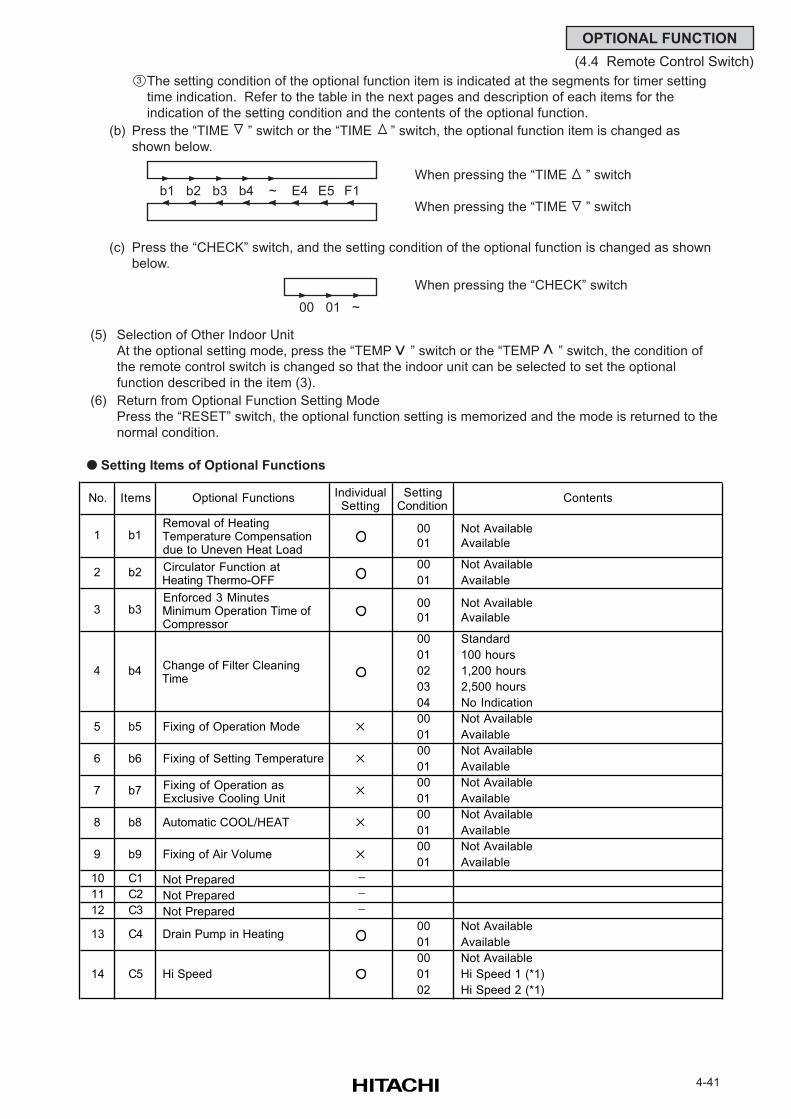
4-41
OPTIONAL FUNCTION
(4.4 Remote Control Switch)
The setting condition of the optional function item is indicated at the segments for timer setting
time indication. Refer to the table in the next pages and description of each items for the
indication of the setting condition and the contents of the optional function.
(b) Press the “TIME ” switch or the “TIME ” switch, the optional function item is changed as
shown below.
(c) Press the “CHECK” switch, and the setting condition of the optional function is changed as shown
below.
When pressing the “CHECK” switch
(5) Selection of Other Indoor Unit
At the optional setting mode, press the “TEMP ” switch or the “TEMP ” switch, the condition of
the remote control switch is changed so that the indoor unit can be selected to set the optional
function described in the item (3).
(6) Return from Optional Function Setting Mode
Press the “RESET” switch, the optional function setting is memorized and the mode is returned to the
normal condition.
Setting Items of Optional Functions
3
>
>
When pressing the “TIME ” switch
When pressing the “TIME ” switch
00 01 ~
b1 b2 b3 b4 ~ E4 E5 F1
No. Items Optional Functions IndividualSetting
SettingCondition
Contents
00 Not Available
01 Available
00 Not Available
01 Available
00 Not Available
01 Available
00 Standard
01 100 hours
02 1,200 hours
03 2,500 hours
04 No Indication
00 Not Available
01 Available
00 Not Available
01 Available
00 Not Available
01 Available
00 Not Available
01 Available
00 Not Available
01 Available
10 C1 Not Prepared −11 C2 Not Prepared −12 C3 Not Prepared −
00 Not Available
01 Available
00 Not Available
01 Hi Speed 1 (*1)
02 Hi Speed 2 (*1)
1
2
3
b1
b2
b3
4
5
6
7
b9
8
9
13
b5
b6
b7
b8
b4
Circulator Function at Heating Thermo-OFF
Enforced 3 Minutes Minimum Operation Time of Compressor
Change of Filter Cleaning Time
Fixing of Operation Mode
Removal of Heating Temperature Compensation due to Uneven Heat Load
C4
C5
Fixing of Setting Temperature
Fixing of Operation as Exclusive Cooling Unit
Automatic COOL/HEAT
Fixing of Air Volume
Drain Pump in Heating
Hi Speed14
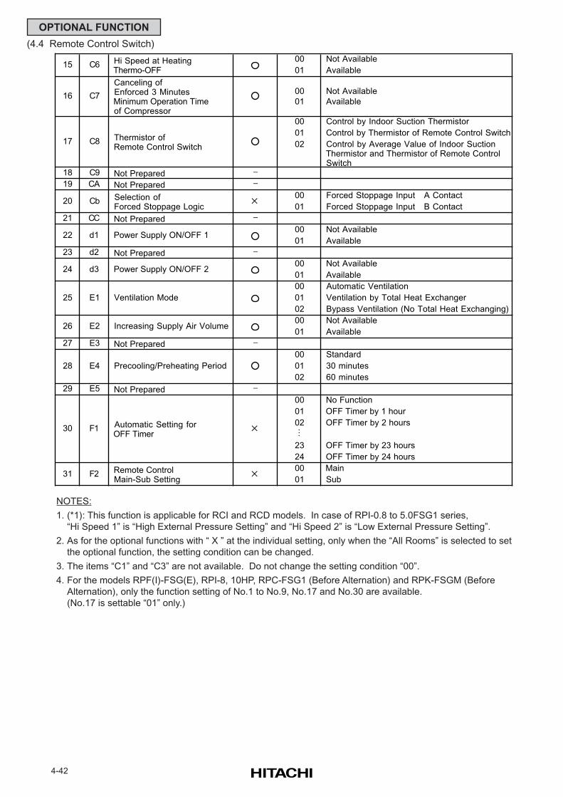
4-42
OPTIONAL FUNCTION
(4.4 Remote Control Switch)
NOTES:
1. (*1): This function is applicable for RCI and RCD models. In case of RPI-0.8 to 5.0FSG1 series,
“Hi Speed 1” is “High External Pressure Setting” and “Hi Speed 2” is “Low External Pressure Setting”.
2. As for the optional functions with “ X ” at the individual setting, only when the “All Rooms” is selected to set
the optional function, the setting condition can be changed.
3. The items “C1” and “C3” are not available. Do not change the setting condition “00”.
4. For the models RPF(I)-FSG(E), RPI-8, 10HP, RPC-FSG1 (Before Alternation) and RPK-FSGM (Before
Alternation), only the function setting of No.1 to No.9, No.17 and No.30 are available.
(No.17 is settable “01” only.)
00 Not Available
01 Available
00 Not Available
01 Available
00 Control by Indoor Suction Thermistor
01 Control by Thermistor of Remote Control Switch
02 Control by Average Value of Indoor Suction Thermistor and Thermistor of Remote Control Switch
18 C9 Not Prepared −19 CA Not Prepared −
00 Forced Stoppage Input A Contact
01 Forced Stoppage Input B Contact
21 CC Not Prepared −00 Not Available
01 Available
23 d2 Not Prepared −00 Not Available
01 Available
00 Automatic Ventilation
01 Ventilation by Total Heat Exchanger
02 Bypass Ventilation (No Total Heat Exchanging)
00 Not Available
01 Available
27 E3 Not Prepared −00 Standard
01 30 minutes
02 60 minutes
29 E5 Not Prepared −00 No Function
01 OFF Timer by 1 hour
02 OFF Timer by 2 hours
M
23 OFF Timer by 23 hours
24 OFF Timer by 24 hours
00 Main
01 Sub
28 E4 Precooling/Preheating Period
24 d3 Power Supply ON/OFF 2
25
26 E2 Increasing Supply Air Volume
20 Cb Selection of Forced Stoppage Logic
E1 Ventilation Mode
22 d1 Power Supply ON/OFF 1
17 C8 Thermistor of Remote Control Switch
30 F1 Automatic Setting for OFF Timer
15 C6 Hi Speed at Heating Thermo-OFF
16 C7
Canceling of Enforced 3 Minutes Minimum Operation Time of Compressor
31 F2 Remote Control Main-Sub Setting
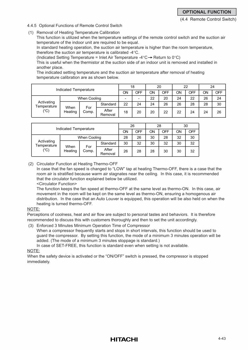
4-43
OPTIONAL FUNCTION
(4.4 Remote Control Switch)
4.4.5 Optional Functions of Remote Control Switch
(1) Removal of Heating Temperature Calibration
This function is utilized when the temperature settings of the remote control switch and the suction air
temperature of the indoor unit are required to be equal.
In standard heating operation, the suction air temperature is higher than the room temperature,
therefore the suction air temperature is calibrated -4°C.
(Indicated Setting Temperature = Inlet Air Temperature -4°C Return to 0°C)
This is useful when the thermistor at the suction side of an indoor unit is removed and installed in
another place.
The indicated setting temperature and the suction air temperature after removal of heating
temperature calibration are as shown below.
(2) Circulator Function at Heating Thermo-OFF
In case that the fan speed is changed to “LOW” tap at heating Thermo-OFF, there is a case that the
room air is stratified because warm air stagnates near the ceiling. In this case, it is recommended
that the circulator function explained below be utilized.
<Circulator Function>
The function keeps the fan speed at thermo-OFF at the same level as thermo-ON. In this case, air
movement in the room will be kept on the same level as thermo-ON, ensuring a homogenous air
distribution. In the case that an Auto Louver is equipped, this operation will be also held on when the
heating is turned thermo-OFF.
NOTE:
Perceptions of coolness, heat and air flow are subject to personal tastes and behaviors. It is therefore
recommended to discuss this with customers thoroughly and then to set the unit accordingly.
(3) Enforced 3 Minutes Minimum Operation Time of Compressor
When a compressor frequently starts and stops in short intervals, this function should be used to
guard the compressor. By setting this function, the mode of a minimum 3 minutes operation will be
added. (The mode of a minimum 3 minutes stoppage is standard.)
In case of SET-FREE, this function is standard even when setting is not available.
NOTE:
When the safety device is activated or the “ON/OFF” switch is pressed, the compressor is stopped
immediately.
ON OFF ON OFF ON OFF ON OFF
- - 22 20 24 22 26 24
Standard 22 24 24 26 26 28 28 30
After Removal
18 20 20 22 22 24 24 26
ON OFF ON OFF ON OFF
28 26 30 28 32 30
Standard 30 32 30 32 30 32
After Removal
26 28 28 30 30 32
Activating Temperature
(oC)
When Cooling
When Heating
For Comp.
Indicated Temperature26 28 30
18 20 22 24Indicated Temperature
Activating Temperature
(oC)
When Cooling
When Heating
For Comp.
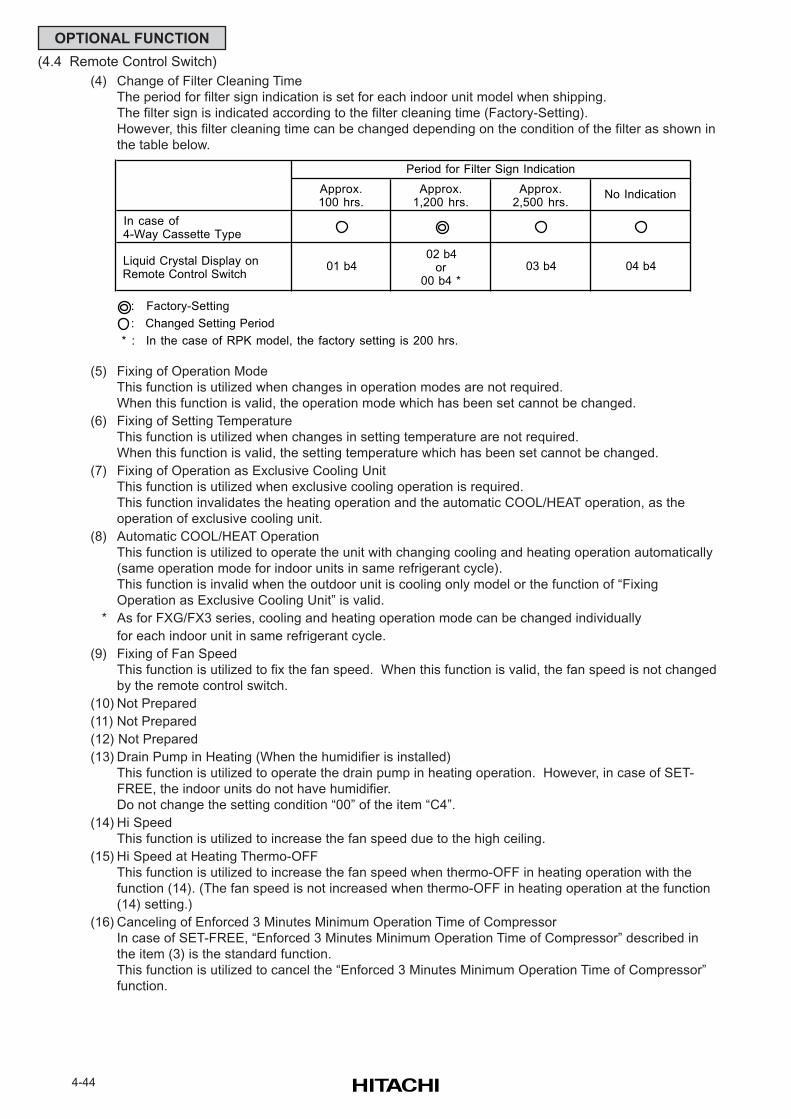
4-44
OPTIONAL FUNCTION
(4.4 Remote Control Switch)
(4) Change of Filter Cleaning Time
The period for filter sign indication is set for each indoor unit model when shipping.
The filter sign is indicated according to the filter cleaning time (Factory-Setting).
However, this filter cleaning time can be changed depending on the condition of the filter as shown in
the table below.
(5) Fixing of Operation Mode
This function is utilized when changes in operation modes are not required.
When this function is valid, the operation mode which has been set cannot be changed.
(6) Fixing of Setting Temperature
This function is utilized when changes in setting temperature are not required.
When this function is valid, the setting temperature which has been set cannot be changed.
(7) Fixing of Operation as Exclusive Cooling Unit
This function is utilized when exclusive cooling operation is required.
This function invalidates the heating operation and the automatic COOL/HEAT operation, as the
operation of exclusive cooling unit.
(8) Automatic COOL/HEAT Operation
This function is utilized to operate the unit with changing cooling and heating operation automatically
(same operation mode for indoor units in same refrigerant cycle).
This function is invalid when the outdoor unit is cooling only model or the function of “Fixing
Operation as Exclusive Cooling Unit” is valid.
* As for FXG/FX3 series, cooling and heating operation mode can be changed individually
for each indoor unit in same refrigerant cycle.
(9) Fixing of Fan Speed
This function is utilized to fix the fan speed. When this function is valid, the fan speed is not changed
by the remote control switch.
(10) Not Prepared
(11) Not Prepared
(12) Not Prepared
(13) Drain Pump in Heating (When the humidifier is installed)
This function is utilized to operate the drain pump in heating operation. However, in case of SET-
FREE, the indoor units do not have humidifier.
Do not change the setting condition “00” of the item “C4”.
(14) Hi Speed
This function is utilized to increase the fan speed due to the high ceiling.
(15) Hi Speed at Heating Thermo-OFF
This function is utilized to increase the fan speed when thermo-OFF in heating operation with the
function (14). (The fan speed is not increased when thermo-OFF in heating operation at the function
(14) setting.)
(16) Canceling of Enforced 3 Minutes Minimum Operation Time of Compressor
In case of SET-FREE, “Enforced 3 Minutes Minimum Operation Time of Compressor” described in
the item (3) is the standard function.
This function is utilized to cancel the “Enforced 3 Minutes Minimum Operation Time of Compressor”
function.
Approx.100 hrs.
Approx.1,200 hrs.
Approx.2,500 hrs.
No Indication
01 b402 b4
or00 b4 *
03 b4 04 b4
: Factory-Setting
: Changed Setting Period
* : In the case of RPK model, the factory setting is 200 hrs.
In case of 4-Way Cassette Type
Liquid Crystal Display on Remote Control Switch
Period for Filter Sign Indication
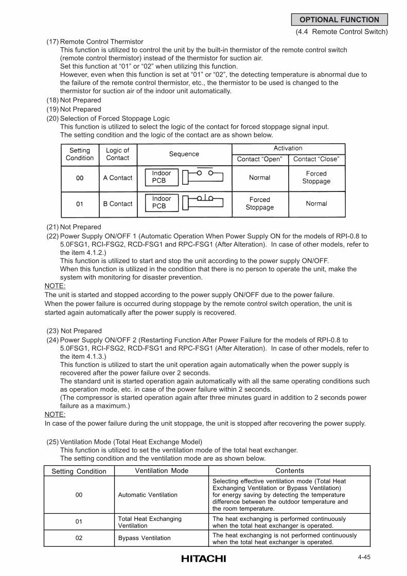
4-45
OPTIONAL FUNCTION
(4.4 Remote Control Switch)
(17) Remote Control Thermistor
This function is utilized to control the unit by the built-in thermistor of the remote control switch
(remote control thermistor) instead of the thermistor for suction air.
Set this function at “01” or “02” when utilizing this function.
However, even when this function is set at “01” or “02”, the detecting temperature is abnormal due to
the failure of the remote control thermistor, etc., the thermistor to be used is changed to the
thermistor for suction air of the indoor unit automatically.
(18) Not Prepared
(19) Not Prepared
(20) Selection of Forced Stoppage Logic
This function is utilized to select the logic of the contact for forced stoppage signal input.
The setting condition and the logic of the contact are as shown below.
(21) Not Prepared
(22) Power Supply ON/OFF 1 (Automatic Operation When Power Supply ON for the models of RPI-0.8 to
5.0FSG1, RCI-FSG2, RCD-FSG1 and RPC-FSG1 (After Alteration). In case of other models, refer to
the item 4.1.2.)
This function is utilized to start and stop the unit according to the power supply ON/OFF.
When this function is utilized in the condition that there is no person to operate the unit, make the
system with monitoring for disaster prevention.
NOTE:
The unit is started and stopped according to the power supply ON/OFF due to the power failure.
When the power failure is occurred during stoppage by the remote control switch operation, the unit is
started again automatically after the power supply is recovered.
(23) Not Prepared
(24) Power Supply ON/OFF 2 (Restarting Function After Power Failure for the models of RPI-0.8 to
5.0FSG1, RCI-FSG2, RCD-FSG1 and RPC-FSG1 (After Alteration). In case of other models, refer to
the item 4.1.3.)
This function is utilized to start the unit operation again automatically when the power supply is
recovered after the power failure over 2 seconds.
The standard unit is started operation again automatically with all the same operating conditions such
as operation mode, etc. in case of the power failure within 2 seconds.
(The compressor is started operation again after three minutes guard in addition to 2 seconds power
failure as a maximum.)
NOTE:
In case of the power failure during the unit stoppage, the unit is stopped after recovering the power supply.
(25) Ventilation Mode (Total Heat Exchange Model)
This function is utilized to set the ventilation mode of the total heat exchanger.
The setting condition and the ventilation mode are as shown below.
Setting Condition Ventilation Mode Contents
00 Automatic Ventilation
Selecting effective ventilation mode (Total Heat Exchanging Ventilation or Bypass Ventilation) for energy saving by detecting the temperature difference between the outdoor temperature and the room temperature.
01 Total Heat Exchanging Ventilation
The heat exchanging is performed continuously when the total heat exchanger is operated.
02 Bypass Ventilation The heat exchanging is not performed continuously when the total heat exchanger is operated.
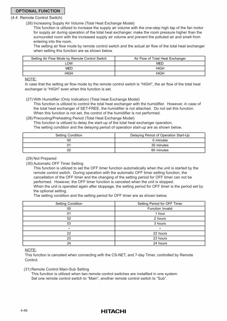
4-46
OPTIONAL FUNCTION
(4.4 Remote Control Switch)
(26) Increasing Supply Air Volume (Total Heat Exchange Model)
This function is utilized to increase the supply air volume with the one-step high tap of the fan motor
for supply air during operation of the total heat exchanger, make the room pressure higher than the
surrounded room with the increased supply air volume and prevent the polluted air and smell from
entering into the room.
The setting air flow mode by remote control switch and the actual air flow of the total heat exchanger
when setting this function are as shown below.
NOTE:
In case that the setting air flow mode by the remote control switch is “HIGH”, the air flow of the total heat
exchanger is “HIGH” even when this function is set.
(27) With Humidifier (Only Indication) (Total Heat Exchange Model)
This function is utilized to control the total heat exchanger with the humidifier. However, in case of
the total heat exchanger of SET-FREE, the humidifier is not attached. Do not set this function.
When this function is not set, the control of the humidifier is not performed.
(28) Precooling/Preheating Period (Total Heat Exchange Model)
This function is utilized to delay the start-up of the total heat exchanger operation.
The setting condition and the delaying period of operation start-up are as shown below.
(29) Not Prepared
(30) Automatic OFF Timer Setting
This function is utilized to set the OFF timer function automatically when the unit is started by the
remote control switch. During operation with the automatic OFF timer setting function, the
cancellation of the OFF timer and the changing of the setting period for OFF timer can not be
performed. However, the OFF timer function is canceled when the unit is stopped.
When the unit is operated again after stoppage, the setting period for OFF timer is the period set by
the optional setting.
The setting condition and the setting period for OFF timer are as shown below.
Air Flow of Total Heat Exchanger
MED
HIGH
HIGH
Setting Air Flow Mode by Remote Control Switch
LOW
MED
HIGH
Delaying Period of Operation Start-Up
0 minutes
30 minutes
60 minutes
Setting Condition
00
01
02
Setting Period for OFF Timer
Function Invalid
1 hour
2 hours
3 hours
~
22 hours
23 hours
24 hours
~
22
23
00
01
02
03
24
Setting Condition
NOTE:
This function is canceled when connecting with the CS-NET, and 7-day Timer, controlled by Remote
Control.
(31) Remote Control Main-Sub Setting
This function is utilized when two remote control switches are installted in one system.
Set one remote control switch to “Main”, another remote control switch to “Sub”.
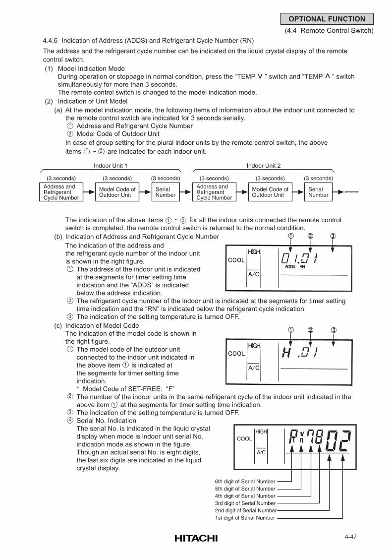
4-47
OPTIONAL FUNCTION
(4.4 Remote Control Switch)
4.4.6 Indication of Address (ADDS) and Refrigerant Cycle Number (RN)
The address and the refrigerant cycle number can be indicated on the liquid crystal display of the remote
control switch.
(1) Model Indication Mode
During operation or stoppage in normal condition, press the “TEMP ” switch and “TEMP ” switch
simultaneously for more than 3 seconds.
The remote control switch is changed to the model indication mode.
(2) Indication of Unit Model
(a) At the model indication mode, the following items of information about the indoor unit connected to
the remote control switch are indicated for 3 seconds serially.
Address and Refrigerant Cycle Number
Model Code of Outdoor Unit
In case of group setting for the plural indoor units by the remote control switch, the above
items ~ are indicated for each indoor unit.
The indication of the above items ~ for all the indoor units connected the remote control
switch is completed, the remote control switch is returned to the normal condition.
(b) Indication of Address and Refrigerant Cycle Number
The indication of the address and
the refrigerant cycle number of the indoor unit
is shown in the right figure.
The address of the indoor unit is indicated
at the segments for timer setting time
indication and the “ADDS” is indicated
below the address indication.
The refrigerant cycle number of the indoor unit is indicated at the segments for timer setting
time indication and the “RN” is indicated below the refrigerant cycle indication.
The indication of the setting temperature is turned OFF.
(c) Indication of Model Code
The indication of the model code is shown in
the right figure.
The model code of the outdoor unit
connected to the indoor unit indicated in
the above item is indicated at
the segments for timer setting time
indication.
* Model Code of SET-FREE: “F”
The number of the indoor units in the same refrigerant cycle of the indoor unit indicated in the
above item at the segments for timer setting time indication.
The indication of the setting temperature is turned OFF.
Serial No. Indication
The serial No. is indicated in the liquid crystal
display when mode is indoor unit serial No.
indication mode as shown in the figure.
Though an actual serial No. is eight digits,
the last six digits are indicated in the liquid
crystal display.
1
2
1 2
1 2
>
>
1
2
3
1
2
3
1
1
Model Code ofOutdoor Unit
SerialNumber
(3 seconds) (3 seconds)
Indoor Unit 1
(3 seconds)
Address andRefrigerantCycle Number
Model Code ofOutdoor Unit
SerialNumber
(3 seconds) (3 seconds)
Indoor Unit 2
(3 seconds)
Address andRefrigerantCycle Number
COOLHIGH
A/C
6th digit of Serial Number 5th digit of Serial Number 4th digit of Serial Number 3rd digit of Serial Number 2nd digit of Serial Number 1st digit of Serial Number
4
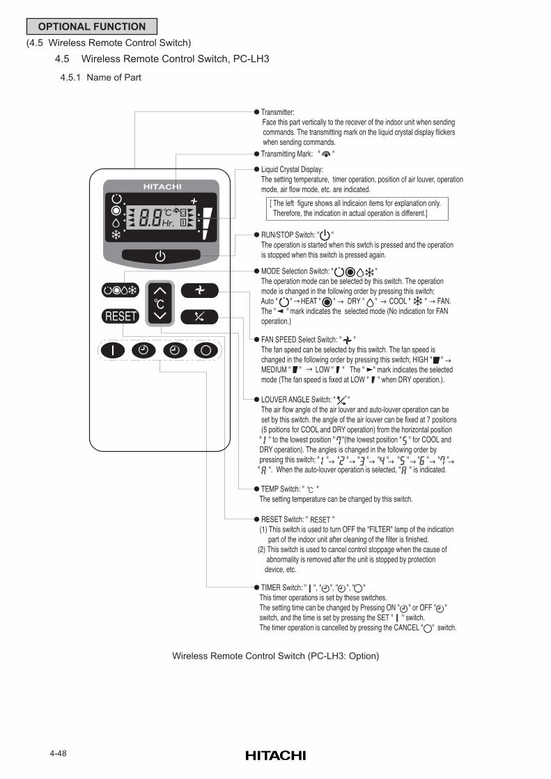
4-48
OPTIONAL FUNCTION
(4.5 Wireless Remote Control Switch)
4.5 Wireless Remote Control Switch, PC-LH3
4.5.1 Name of Part
Wireless Remote Control Switch (PC-LH3: Option)
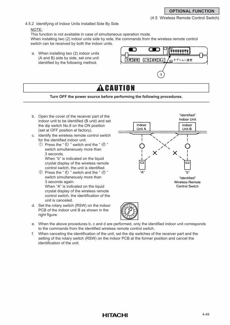
4-49
OPTIONAL FUNCTION
(4.5 Wireless Remote Control Switch)
4.5.2 Identifying of Indoor Units Installed Side By Side
NOTE:
This function is not available in case of simultaneous operation mode.
When installing two (2) indoor units side by side, the commands from the wireless remote control
switch can be received by both the indoor units.
a. When installing two (2) indoor units
(A and B) side by side, set one unit
identified by the following method.
b. Open the cover of the receiver part of the
indoor unit to be identified (B unit) and set
the dip switch No.8 on the ON position
(set at OFF position at factory).
c. Identify the wireless remote control switch
for the identified indoor unit.
Press the “ ” switch and the “ ”
switch simultaneously more than
3 seconds.
When “b” is indicated on the liquid
crystal display of the wireless remote
control switch, the unit is identified.
Press the “ ” switch and the “ ”
switch simultaneously more than
3 seconds again.
When “A” is indicated on the liquid
crystal display of the wireless remote
control switch, the identification of the
unit is canceled.
d. Set the rotary switch (RSW) on the indoor
PCB of the indoor unit B as shown in the
right figure.
e. When the above procedures b, c and d are performed, only the identified indoor unit corresponds
to the commands from the identified wireless remote control switch.
f. When canceling the identification of the unit, set the dip switches of the receiver part and the
setting of the rotary switch (RSW) on the indoor PCB at the former position and cancel the
identification of the unit.
Turn OFF the power source before performing the following procedures.
1
2
1
01 2
34
5
67
8
9ABC
E F
D
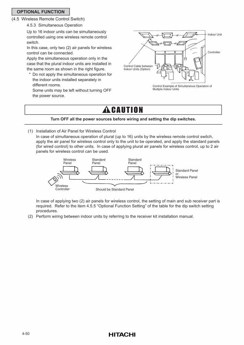
4-50
OPTIONAL FUNCTION
(4.5 Wireless Remote Control Switch)
4.5.3 Simultaneous Operation
Up to 16 indoor units can be simultaneously
controlled using one wireless remote control
switch.
In this case, only two (2) air panels for wireless
control can be connected.
Apply the simultaneous operation only in the
case that the plural indoor units are installed in
the same room as shown in the right figure.
* Do not apply the simultaneous operation for
the indoor units installed separately in
different rooms.
Some units may be left without turning OFF
the power source.
In case of applying two (2) air panels for wireless control, the setting of main and sub receiver part is
required. Refer to the item 4.5.5 “Optional Function Setting” of the table for the dip switch setting
procedures.
(2) Perform wiring between indoor units by referring to the receiver kit installation manual.
Turn OFF all the power sources before wiring and setting the dip switches.
(1) Installation of Air Panel for Wireless Control
In case of simultaneous operation of plural (up to 16) units by the wireless remote control switch,
apply the air panel for wireless control only to the unit to be operated, and apply the standard panels
(for wired control) to other units. In case of applying plural air panels for wireless control, up to 2 air
panels for wireless control can be used.
Control Cable betweenIndoor Units (Option)
Indoor Unit
Controller
Control Example of Simultaneous Operation ofMultiple Indoor Units
WirelessPanel
WirelessController
StandardPanel
StandardPanel
Standard PanelorWireless Panel
Should be Standard Panel
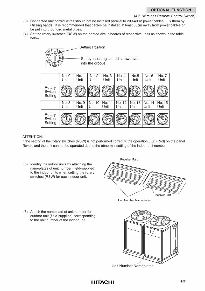
4-51
OPTIONAL FUNCTION
(4.5 Wireless Remote Control Switch)
(3) Connected unit control wires should not be installed parallel to 200-400V power cables. Fix them by
utilizing bands. It is recommended that cables be installed at least 30cm away from power cables or
be put into grounded metal pipes.
(4) Set the rotary switches (RSW) on the printed circuit boards of respective units as shown in the table
below.
ATTENTION:
If the setting of the rotary switches (RSW) is not performed correctly, the operation LED (Red) on the panel
flickers and the unit can not be operated due to the abnormal setting of the indoor unit number.
(6) Attach the nameplate of unit number for
outdoor unit (field-supplied) corresponding
to the unit number of the indoor unit.
(5) Identify the indoor units by attaching the
nameplates of unit number (field-supplied)
to the indoor units when setting the rotary
switches (RSW) for each indoor unit.
01 2
34
5
67
8
9ABC
E FD
RotarySwitchSetting
RotarySwitchSetting
No. 0Unit
No. 1Unit
No. 2Unit
No. 3Unit
No. 4Unit
No.5Unit
No. 6Unit
No. 7Unit
No. 8Unit
No. 9Unit
No. 10Unit
No. 11Unit
No. 12Unit
No. 13Unit
No. 14Unit
No. 15Unit
Setting Position
Set by inserting slotted screwdriver into the groove
01 2
34
5
67
8
9ABC
E F
D
01 2
34
5
67
8
9ABC
E F
D
01 2
34
5
67
8
9ABC
E F
D
01 2
34
567
8
9ABC
E F
D
01 2
34
5
67
8
9ABC
E F
D
01 2
34
5
67
8
9ABC
E F
D
01 2
34
5
67
8
9ABC
E F
D
01 2
34
5
67
8
9ABC
E F
D
01 2
34
5
67
8
9ABC
E F
D
01 2
34
567
8
9ABC
E F
D
01 2
34
5
67
8
9ABC
E F
D
01 2
34
5
67
8
9ABC
E F
D
01 2
34
5
67
8
9ABC
E FD
01 2
34
5
67
8
9ABC
E F
D
01 2
34
5
67
8
9ABC
E F
D
01 2
34
5
67
8
9ABC
E F
D
Receiver Part
Unit Number Nameplates
Receiver Part
Unit Number Nameplates
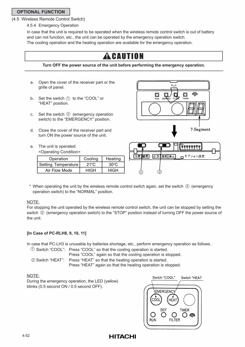
4-52
OPTIONAL FUNCTION
(4.5 Wireless Remote Control Switch)
4.5.4 Emergency Operation
In case that the unit is required to be operated when the wireless remote control switch is out of battery
and can not function, etc., the unit can be operated by the emergency operation switch.
The cooling operation and the heating operation are available for the emergency operation.
* When operating the unit by the wireless remote control switch again, set the switch (emergency
operation switch) to the “NORMAL” position.
NOTE:
For stopping the unit operated by the wireless remote control switch, the unit can be stopped by setting the
switch (emergency operation switch) to the “STOP” position instead of turning OFF the power source of
the unit.
Turn OFF the power source of the unit before performing the emergency operation.
a. Open the cover of the receiver part or the
grille of panel.
b. Set the switch to the “COOL” or
“HEAT” position.
c. Set the switch (emergency operation
switch) to the “EMERGENCY” position.
d. Close the cover of the receiver part and
turn ON the power source of the unit.
e. The unit is operated.
<Operating Condition>
1
2
2
2
[In Case of PC-RLH8, 9, 10, 11]
In case that PC-LH3 is unusable by batteries shortage, etc., perform emergency operation as follows.
Switch “COOL”: Press “COOL” so that the cooling operation is started.
Press “COOL” again so that the cooling operation is stopped.
Switch “HEAT”: Press “HEAT” so that the heating operation is started.
Press “HEAT” again so that the heating operation is stopped.
NOTE:
During the emergency operation, the LED (yellow)
blinks (0.5 second ON / 0.5 second OFF).
1
2
Operation Cooling Heating
Setting Temperature 21oC 30oC
Air Flow Mode HIGH HIGH
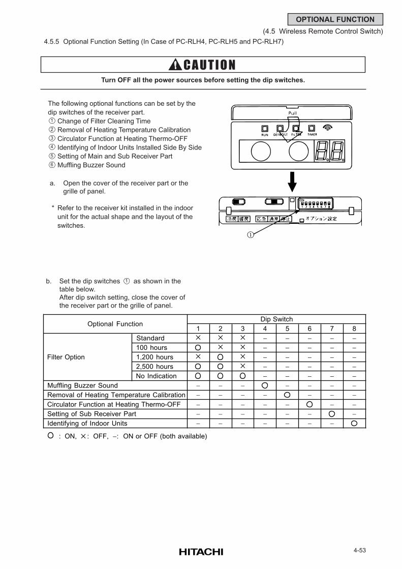
4-53
OPTIONAL FUNCTION
(4.5 Wireless Remote Control Switch)
4.5.5 Optional Function Setting (In Case of PC-RLH4, PC-RLH5 and PC-RLH7)
b. Set the dip switches as shown in the
table below.
After dip switch setting, close the cover of
the receiver part or the grille of panel.
The following optional functions can be set by the
dip switches of the receiver part.
Change of Filter Cleaning Time
Removal of Heating Temperature Calibration
Circulator Function at Heating Thermo-OFF
Identifying of Indoor Units Installed Side By Side
Setting of Main and Sub Receiver Part
Muffling Buzzer Sound
a. Open the cover of the receiver part or the
grille of panel.
* Refer to the receiver kit installed in the indoor
unit for the actual shape and the layout of the
switches.
Turn OFF all the power sources before setting the dip switches.
1
2
3
4
5
6
1
1 2 3 4 5 6 7 8
Standard − − − − − 100 hours − − − − − 1,200 hours − − − − − 2,500 hours − − − − − No Indication − − − − −
Muffling Buzzer Sound − − − − − − − Removal of Heating Temperature Calibration − − − − − − − Circulator Function at Heating Thermo-OFF − − − − − − − Setting of Sub Receiver Part − − − − − − − Identifying of Indoor Units − − − − − − −
: ON, : OFF, −: ON or OFF (both available)
Filter Option
Optional FunctionDip Switch
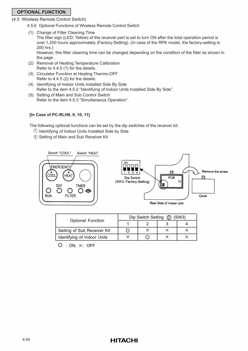
4-54
OPTIONAL FUNCTION
(4.5 Wireless Remote Control Switch)
4.5.6 Optional Functions of Wireless Remote Control Switch
(1) Change of Filter Cleaning Time
The filter sign (LED; Yellow) of the receiver part is set to turn ON after the total operation period is
over 1,200 hours approximately (Factory-Setting). (In case of the RPK model, the factory-setting is
200 hrs.)
However, this filter cleaning time can be changed depending on the condition of the filter as shown in
the page .
(2) Removal of Heating Temperature Calibration
Refer to 4.4.5 (1) for the details.
(3) Circulator Function at Heating Thermo-OFF
Refer to 4.4.5 (2) for the details.
(4) Identifying of Indoor Units Installed Side By Side
Refer to the item 4.5.2 “Identifying of Indoor Units Installed Side By Side”.
(5) Setting of Main and Sub Control Switch
Refer to the item 4.5.3 “Simultaneous Operation”.
[In Case of PC-RLH8, 9, 10, 11]
The following optional functions can be set by the dip switches of the receiver kit.
Identifying of Indoor Units Installed Side by Side
Setting of Main and Sub Receiver Kit
1
2
1 2 3 4
Setting of Sub Receiver Kit
Identifying of Indoor Units
: ON, : OFF
Optional FunctionDip Switch Setting 3 (SW3)
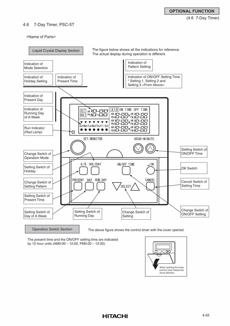
4-55
OPTIONAL FUNCTION
(4.6 7-Day Timer)
4.6 7-Day Timer, PSC-5T
<Name of Parts>
Liquid Crystal Display Section The figure below shows all the indications for reference.The actual display during operation is different.
Indication of Mode Selection
Indication of Holiday Setting
Indication of Present Time
Indication of Present Day
Indication of Running Day of A Week
Run Indicator (Red Lamp)
Change Switch of Operation Mode
Setting Switch of Holiday
Change Switch of Setting Pattern
Setting Switch of Present Time
Setting Switch of Day of A Week
Setting Switch of Running Day
Change Switch of Setting
Indication of Pattern Setting
Indication of ON/OFF Setting Time* Setting 1, Setting 2 and Setting 3 <From Above>
Setting Switch of ON/OFF Time
OK Switch
Cancel Switch of Setting Time
Change Switch of ON/OFF Setting
Operation Switch Section The above figure shows the control timer with the cover opened.
The present time and the ON/OFF setting time are indicated by 12 hour units (AM0:00 – 12:00, PM0:00 – 12:00).
When opening the cover,pull the cover foward the arrow direction.
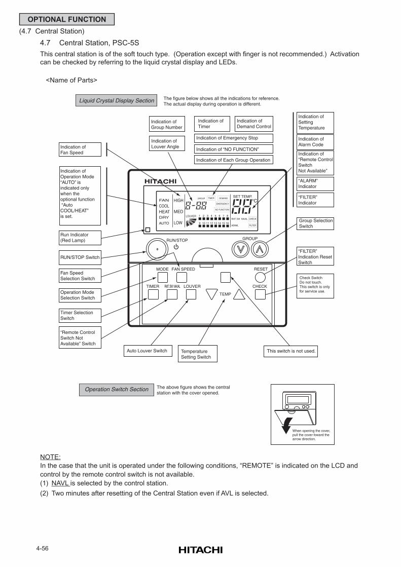
4-56
OPTIONAL FUNCTION
(4.7 Central Station)
4.7 Central Station, PSC-5S
This central station is of the soft touch type. (Operation except with finger is not recommended.) Activation
can be checked by referring to the liquid crystal display and LEDs.
<Name of Parts>
NOTE:
In the case that the unit is operated under the following conditions, “REMOTE” is indicated on the LCD and
control by the remote control switch is not available.
(1) NAVL is selected by the control station.
(2) Two minutes after resetting of the Central Station even if AVL is selected.
1 2 3 4 5 6 7 8
161514131211109
RMT. SW NAVAL
GROUP TIMER
EMERGENCY
RUN/STOP GROUP
SET TEMP.FAN
COOLHEATDRY
AUTO
HIGH
MED
LOW
DEMAND
NO FUNCTION
LOUVER
ABNML
CHECK
FILTER
MODE
TIMER LOUVER CHECK
TEMP
FAN SPEED RESET
RMT. SW NAVAL
Liquid Crystal Display Section The figure below shows all the indications for reference.The actual display during operation is different.
Indication of Group Number
Indication of Louver Angle
Indication of Timer
Indication of Demand Control
Indication of Emergency Stop
Indication of “NO FUNCTION”
Indication of Each Group Operation
Indication of Setting Temperature
Indication of Alarm Code
Indication of “Remote Control Switch Not Available”
“ALARM” Indicator
“FILTER” Indicator
Group Selection Switch
“FILTER” Indication Reset Switch
Check SwitchDo not touch.This switch is only for service use.
Indication of Fan Speed
Indication of Operation Mode“AUTO” is indicated only when the optional function “Auto COOL/HEAT” is set.
Run Indicator (Red Lamp)
RUN/STOP Switch
Fan Speed Selection Switch
Operation Mode Selection Switch
Timer Selection Switch
“Remote Control Switch Not Available” Switch
Auto Louver Switch Temperature Setting Switch
This switch is not used.
Operation Switch Section The above figure shows the central station with the cover opened.
When opening the cover,pull the cover foward the arrow direction.
5-1
FIELD WORK INSTRUCTION
5. FIELD WORK INSTRUCTION
5.1 Burnt-out Compressor due to Insufficient Refrigerant Charge
Question and Answer for Field Work
Example 1: Burnt-out Compressor due to InsufficientRefrigerant Charge
[Phenomenon]After commissioning, alarm code “08” sometimes occurred and compressors were burnt out after
2 month operation.
[Cause]Refrigerant piping work was performed during summer season. Additional refrigerant was not
sufficiently charged from the discharge side.
This insufficient refrigerant charge resulted in discharge gas overheating and oil deterioration finally
due to separated operation despite “08” alarm.
[Countermeasure]1. The compressor was replaced with a new one.
2. Correct refrigerant amount was charged according to refrigerant piping length and connected indoor
units.
[Remarks]Additional Refrigerant Charging:
Open the liquid stop valve slightly when the additional refrigerant is charged from the check joint of
the liquid stop valve (discharge side) during the cooling operation. If the liquid valve is fully open, it is
difficult to charge the additional refrigerant. Do not charge refrigerant from the gas stop valve.
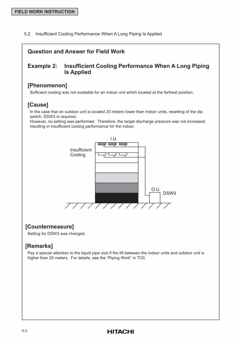
5-2
FIELD WORK INSTRUCTION
[Countermeasure]Setting for DSW3 was changed.
[Remarks]Pay a special attention to the liquid pipe size if the lift between the indoor units and outdoor unit is
higher than 20 meters. For details, see the “Piping Work” in TCII.
Question and Answer for Field Work
Example 2: Insufficient Cooling Performance When A Long PipingIs Applied
[Phenomenon]Sufficient cooling was not available for an indoor unit which located at the farthest position.
[Cause]In the case that an outdoor unit is located 20 meters lower than indoor units, resetting of the dip
switch, DSW3 is required.
However, no setting was performed. Therefore, the target discharge pressure was not increased,
resulting in insufficient cooling performance for the indoor.
5.2 Insufficient Cooling Performance When A Long Piping Is Applied
I.U.
InsufficientCooling
O.U.DSW3
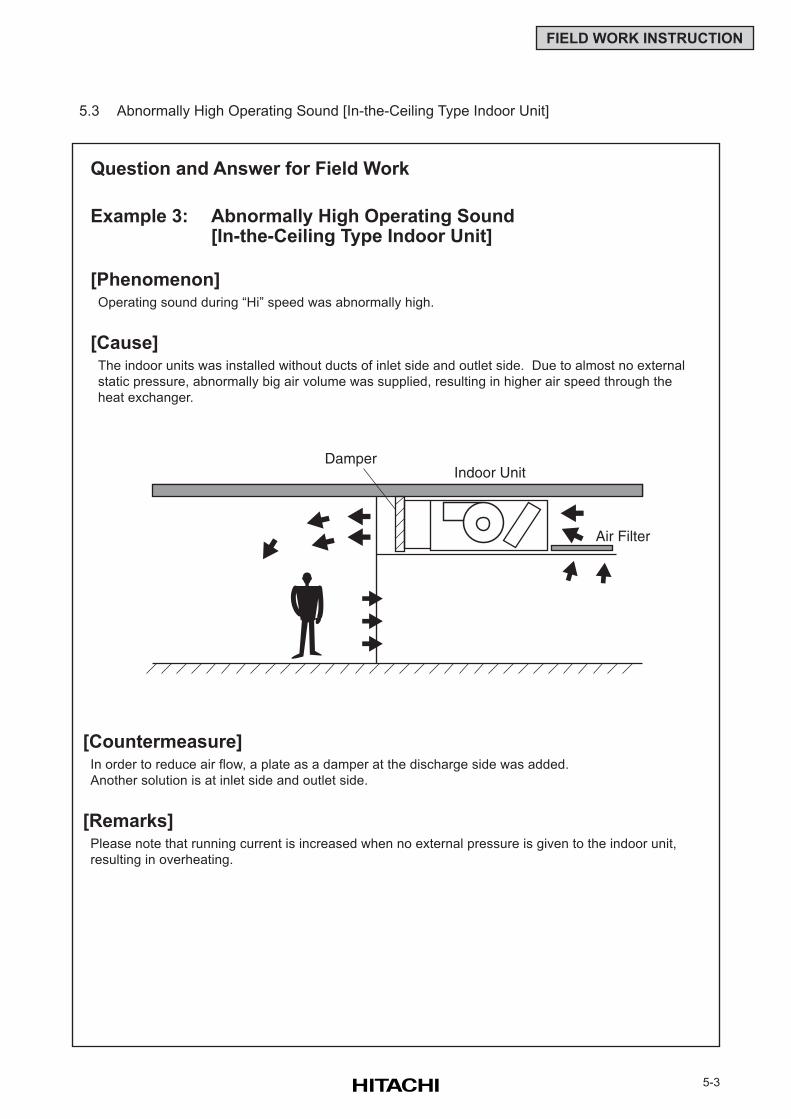
5-3
FIELD WORK INSTRUCTION
5.3 Abnormally High Operating Sound [In-the-Ceiling Type Indoor Unit]
Question and Answer for Field Work
Example 3: Abnormally High Operating Sound[In-the-Ceiling Type Indoor Unit]
[Phenomenon]Operating sound during “Hi” speed was abnormally high.
[Cause]The indoor units was installed without ducts of inlet side and outlet side. Due to almost no external
static pressure, abnormally big air volume was supplied, resulting in higher air speed through the
heat exchanger.
[Countermeasure]In order to reduce air flow, a plate as a damper at the discharge side was added.
Another solution is at inlet side and outlet side.
[Remarks]Please note that running current is increased when no external pressure is given to the indoor unit,
resulting in overheating.
Air Filter
DamperIndoor Unit
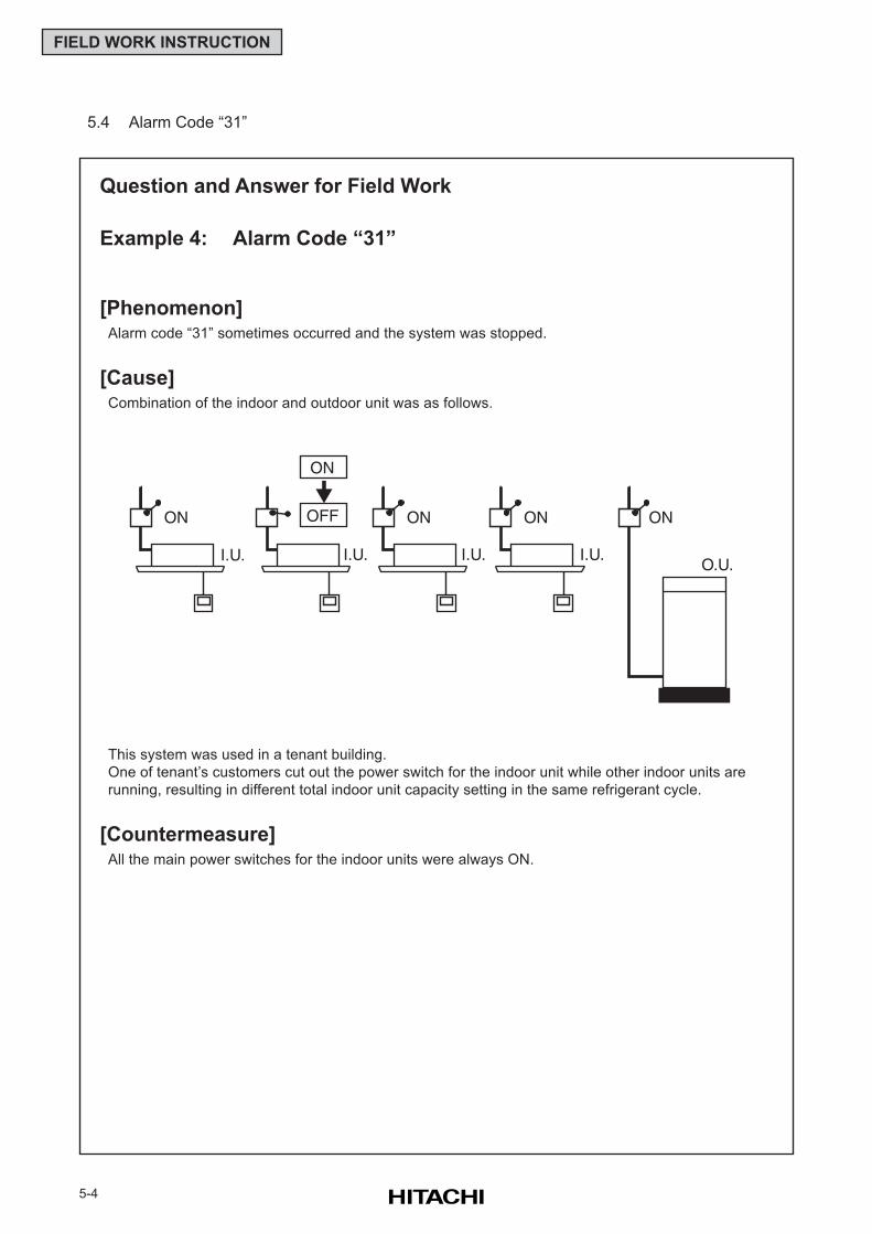
5-4
FIELD WORK INSTRUCTION
This system was used in a tenant building.
One of tenant’s customers cut out the power switch for the indoor unit while other indoor units are
running, resulting in different total indoor unit capacity setting in the same refrigerant cycle.
[Countermeasure]All the main power switches for the indoor units were always ON.
Question and Answer for Field Work
Example 4: Alarm Code “31”
[Phenomenon]Alarm code “31” sometimes occurred and the system was stopped.
[Cause]Combination of the indoor and outdoor unit was as follows.
5.4 Alarm Code “31”
ON ON ON
ON
OFF ON
O.U.I.U. I.U. I.U. I.U.
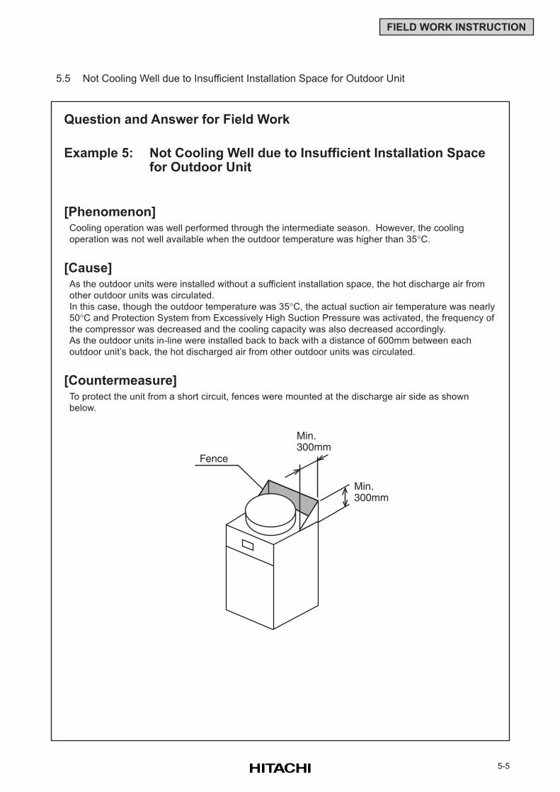
5-5
FIELD WORK INSTRUCTION
Question and Answer for Field Work
Example 5: Not Cooling Well due to Insufficient Installation Spacefor Outdoor Unit
[Phenomenon]Cooling operation was well performed through the intermediate season. However, the cooling
operation was not well available when the outdoor temperature was higher than 35°C.
[Cause]As the outdoor units were installed without a sufficient installation space, the hot discharge air from
other outdoor units was circulated.
In this case, though the outdoor temperature was 35°C, the actual suction air temperature was nearly
50°C and Protection System from Excessively High Suction Pressure was activated, the frequency of
the compressor was decreased and the cooling capacity was also decreased accordingly.
As the outdoor units in-line were installed back to back with a distance of 600mm between each
outdoor unit’s back, the hot discharged air from other outdoor units was circulated.
[Countermeasure]To protect the unit from a short circuit, fences were mounted at the discharge air side as shown
below.
5.5 Not Cooling Well due to Insufficient Installation Space for Outdoor Unit
Fence
Min.300mm
Min.300mm
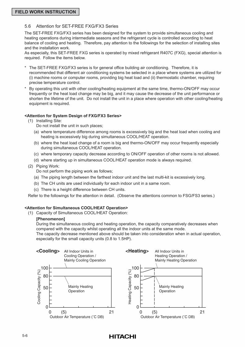
5-6
FIELD WORK INSTRUCTION
5.6 Attention for SET-FREE FXG/FX3 Series
The SET-FREE FXG/FX3 series has been designed for the system to provide simultaneous cooling and
heating operations during intermediate seasons and the refrigerant cycle is controlled according to heat
balance of cooling and heating. Therefore, pay attention to the followings for the selection of installing sites
and the installation work.
As especially, this SET-FREE FXG series is operated by mixed refrigerant R407C (FXG), special attention is
required. Follow the items below.
* The SET-FREE FXG/FX3 series is for general office building air conditioning. Therefore, it is
recommended that different air conditioning systems be selected in a place where systems are utilized for
(i) machine rooms or computer rooms, providing big heat load and (ii) thermostatic chamber, requiring
precise temperature control.
* By operating this unit with other cooling/heating equipment at the same time, thermo-ON/OFF may occur
frequently or the heat load change may be big, and it may cause the decrease of the unit performance or
shorten the lifetime of the unit. Do not install the unit in a place where operation with other cooling/heating
equipment is required.
<Attention for System Design of FXG/FX3 Series>
(1) Installing Site:
Do not install the unit in such places;
(a) where temperature difference among rooms is excessively big and the heat load when cooling and
heating is excessively big during simultaneous COOL/HEAT operation.
(b) where the heat load change of a room is big and thermo-ON/OFF may occur frequently especially
during simultaneous COOL/HEAT operation.
(c) where temporary capacity decrease according to ON/OFF operation of other rooms is not allowed.
(d) where starting up in simultaneous COOL/HEAT operation mode is always required.
(2) Piping Work:
Do not perform the piping work as follows;
(a) The piping length between the farthest indoor unit and the last multi-kit is excessively long.
(b) The CH units are used individually for each indoor unit in a same room.
(c) There is a height difference between CH units.
Refer to the followings for the attention in detail. (Observe the attentions common to FSG/FS3 series.)
<Attention for Simultaneous COOL/HEAT Operation>
(1) Capacity of Simultaneous COOL/HEAT Operation:
[Phenomenon]
During the simultaneous cooling and heating operation, the capacity comparatively decreases when
compared with the capacity whilst operating all the indoor units at the same mode.
The capacity decrease mentioned above should be taken into consideration when in actual operation,
especially for the small capacity units (0.8 to 1.5HP).
100
80
50
00 (5) 21Outdoor Air Temperature (˚C DB)
Mainly HeatingOperation
All Indoor Units inCooling Operation /Mainly Cooling Operation
Coo
ling
Cap
acity
(%
) 100
80
50
00 (5) 21Outdoor Air Temperature (˚C DB)
Mainly HeatingOperation
All Indoor Units inHeating Operation /Mainly Heating Operation
Hea
ting
Cap
acity
(%
)
<Cooling> <Heating>
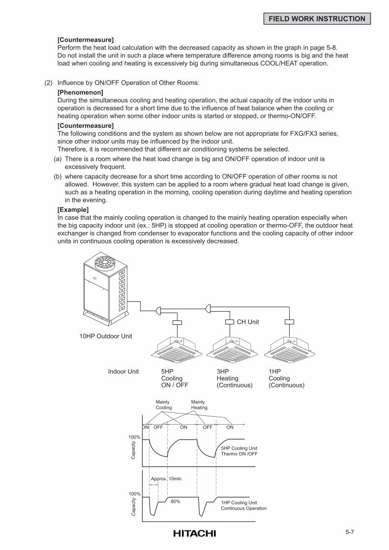
5-7
FIELD WORK INSTRUCTION
[Countermeasure]
Perform the heat load calculation with the decreased capacity as shown in the graph in page 5-8.
Do not install the unit in such a place where temperature difference among rooms is big and the heat
load when cooling and heating is excessively big during simultaneous COOL/HEAT operation.
(2) Influence by ON/OFF Operation of Other Rooms:
[Phenomenon]
During the simultaneous cooling and heating operation, the actual capacity of the indoor units in
operation is decreased for a short time due to the influence of heat balance when the cooling or
heating operation when some other indoor units is started or stopped, or thermo-ON/OFF.
[Countermeasure]
The following conditions and the system as shown below are not appropriate for FXG/FX3 series,
since other indoor units may be influenced by the indoor unit.
Therefore, it is recommended that different air conditioning systems be selected.
(a) There is a room where the heat load change is big and ON/OFF operation of indoor unit is
excessively frequent.
(b) where capacity decrease for a short time according to ON/OFF operation of other rooms is not
allowed. However, this system can be applied to a room where gradual heat load change is given,
such as a heating operation in the morning, cooling operation during daytime and heating operation
in the evening.
[Example]
In case that the mainly cooling operation is changed to the mainly heating operation especially when
the big capacity indoor unit (ex.: 5HP) is stopped at cooling operation or thermo-OFF, the outdoor heat
exchanger is changed from condenser to evaporator functions and the cooling capacity of other indoor
units in continuous cooling operation is excessively decreased.
10HP Outdoor Unit
CH Unit
Indoor Unit 5HPCooling ON / OFF
3HPHeating(Continuous)
1HPCooling (Continuous)
ON OFF ON OFF ON
5HP Cooling Unit
Thermo ON /OFF
1HP Cooling Unit
Continuous Operation
80%
Approx. 10min.
100%
Ca
pa
city
100%
Ca
pa
city
Mainly
Cooling
Mainly
Heating
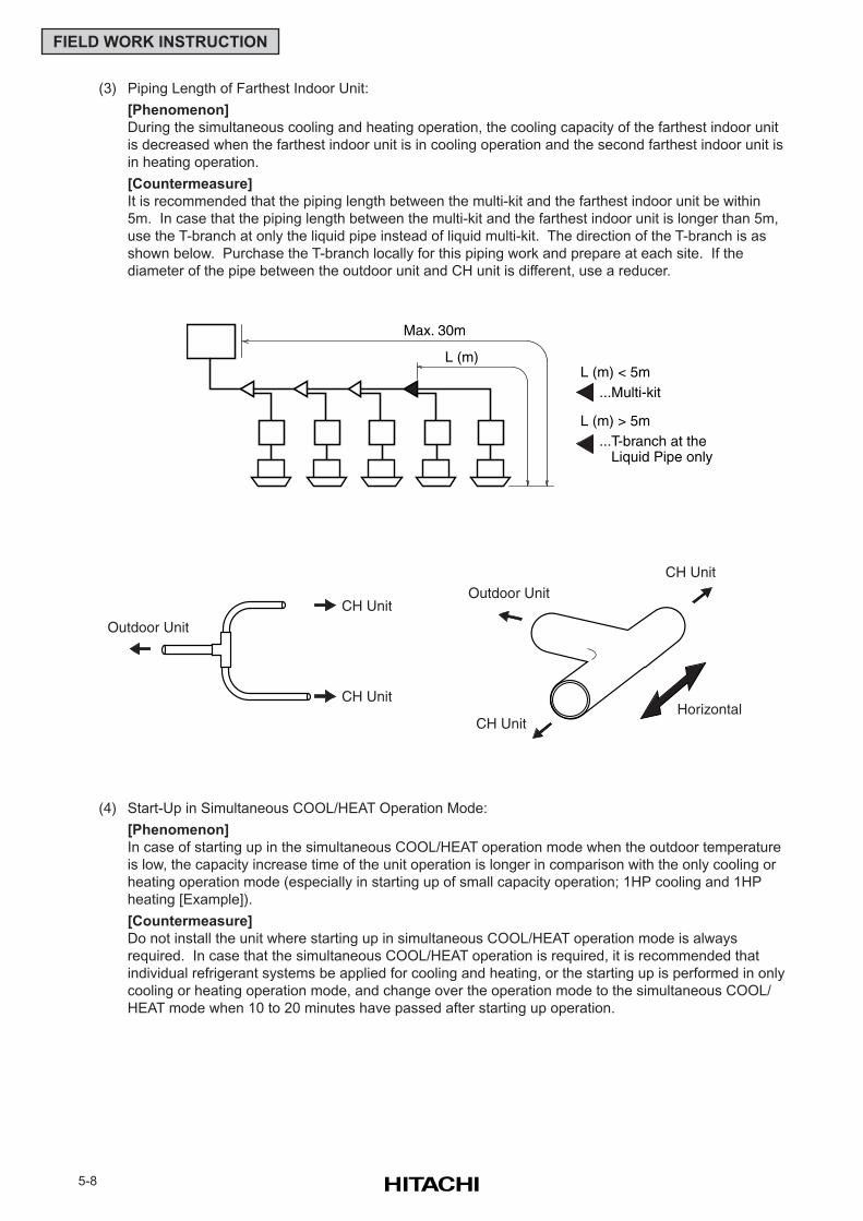
5-8
FIELD WORK INSTRUCTION
(3) Piping Length of Farthest Indoor Unit:
[Phenomenon]
During the simultaneous cooling and heating operation, the cooling capacity of the farthest indoor unit
is decreased when the farthest indoor unit is in cooling operation and the second farthest indoor unit is
in heating operation.
[Countermeasure]
It is recommended that the piping length between the multi-kit and the farthest indoor unit be within
5m. In case that the piping length between the multi-kit and the farthest indoor unit is longer than 5m,
use the T-branch at only the liquid pipe instead of liquid multi-kit. The direction of the T-branch is as
shown below. Purchase the T-branch locally for this piping work and prepare at each site. If the
diameter of the pipe between the outdoor unit and CH unit is different, use a reducer.
(4) Start-Up in Simultaneous COOL/HEAT Operation Mode:
[Phenomenon]
In case of starting up in the simultaneous COOL/HEAT operation mode when the outdoor temperature
is low, the capacity increase time of the unit operation is longer in comparison with the only cooling or
heating operation mode (especially in starting up of small capacity operation; 1HP cooling and 1HP
heating [Example]).
[Countermeasure]
Do not install the unit where starting up in simultaneous COOL/HEAT operation mode is always
required. In case that the simultaneous COOL/HEAT operation is required, it is recommended that
individual refrigerant systems be applied for cooling and heating, or the starting up is performed in only
cooling or heating operation mode, and change over the operation mode to the simultaneous COOL/
HEAT mode when 10 to 20 minutes have passed after starting up operation.
L (m) < 5m
L (m) > 5m
...Multi-kit
...T-branch at the Liquid Pipe only
Max. 30m
L (m)
Outdoor Unit
CH Unit
CH Unit
CH Unit
Outdoor Unit
CH Unit
Horizontal
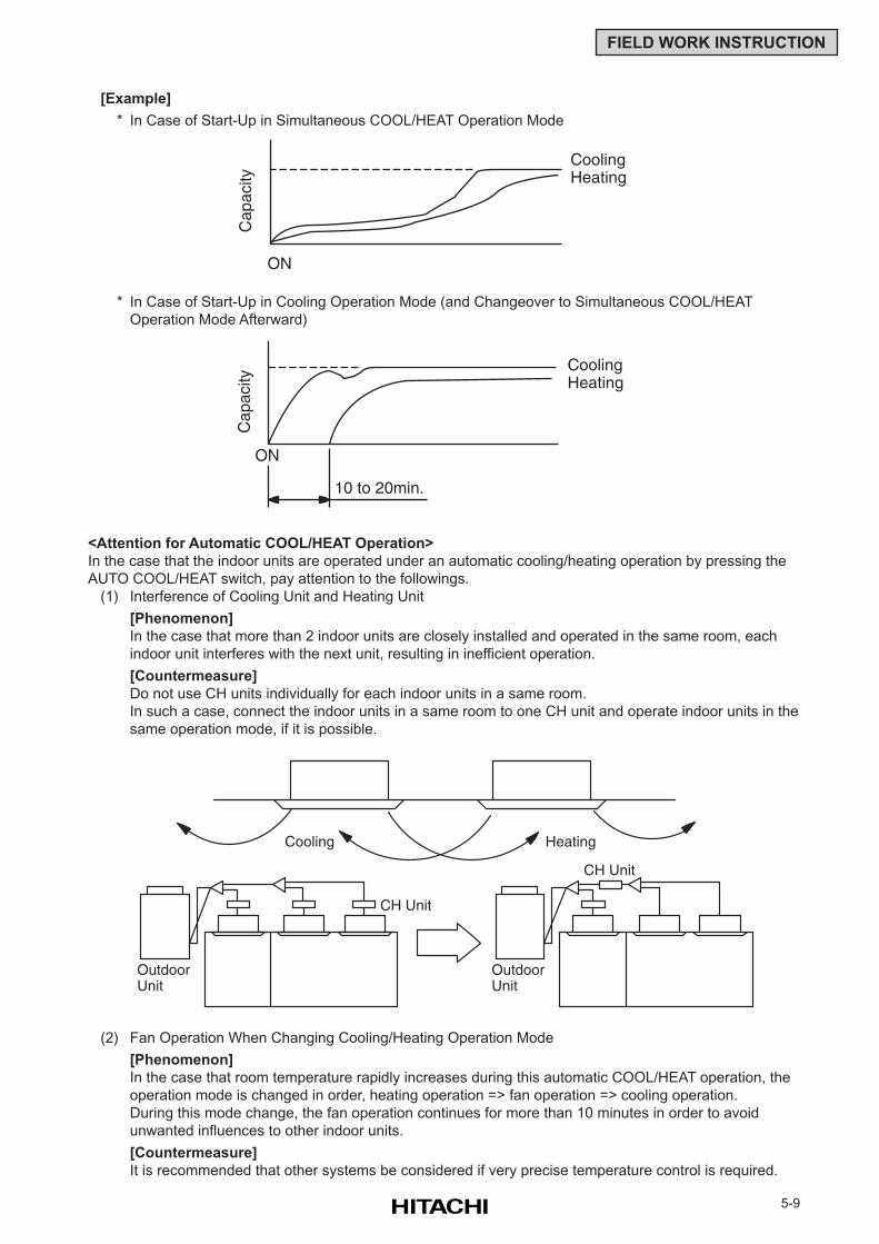
5-9
FIELD WORK INSTRUCTION
[Example]
* In Case of Start-Up in Simultaneous COOL/HEAT Operation Mode
* In Case of Start-Up in Cooling Operation Mode (and Changeover to Simultaneous COOL/HEAT
Operation Mode Afterward)
<Attention for Automatic COOL/HEAT Operation>
In the case that the indoor units are operated under an automatic cooling/heating operation by pressing the
AUTO COOL/HEAT switch, pay attention to the followings.
(1) Interference of Cooling Unit and Heating Unit
[Phenomenon]
In the case that more than 2 indoor units are closely installed and operated in the same room, each
indoor unit interferes with the next unit, resulting in inefficient operation.
[Countermeasure]
Do not use CH units individually for each indoor units in a same room.
In such a case, connect the indoor units in a same room to one CH unit and operate indoor units in the
same operation mode, if it is possible.
(2) Fan Operation When Changing Cooling/Heating Operation Mode
[Phenomenon]
In the case that room temperature rapidly increases during this automatic COOL/HEAT operation, the
operation mode is changed in order, heating operation => fan operation => cooling operation.
During this mode change, the fan operation continues for more than 10 minutes in order to avoid
unwanted influences to other indoor units.
[Countermeasure]
It is recommended that other systems be considered if very precise temperature control is required.
ONC
apac
ity
CoolingHeating
ON
10 to 20min.
Cap
acity
CoolingHeating
Cooling Heating
CH Unit
CH Unit
OutdoorUnit
OutdoorUnit
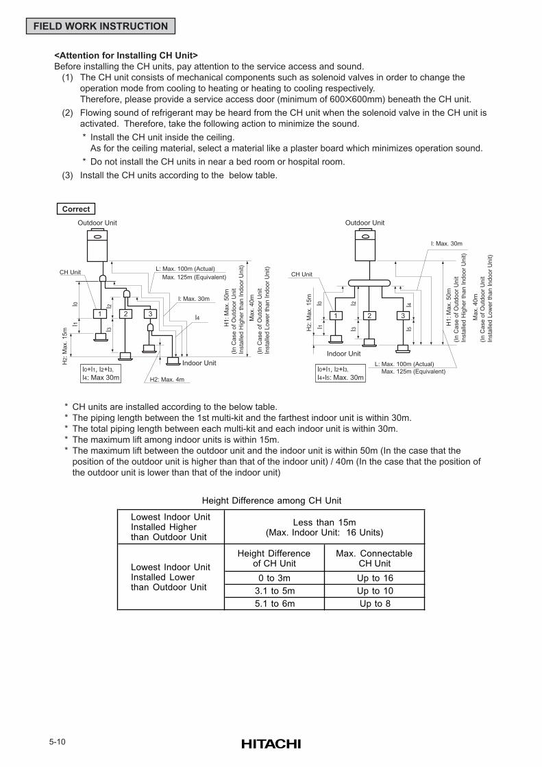
5-10
FIELD WORK INSTRUCTION
<Attention for Installing CH Unit>
Before installing the CH units, pay attention to the service access and sound.
(1) The CH unit consists of mechanical components such as solenoid valves in order to change the
operation mode from cooling to heating or heating to cooling respectively.
Therefore, please provide a service access door (minimum of 600600mm) beneath the CH unit.
(2) Flowing sound of refrigerant may be heard from the CH unit when the solenoid valve in the CH unit is
activated. Therefore, take the following action to minimize the sound.
* Install the CH unit inside the ceiling.
As for the ceiling material, select a material like a plaster board which minimizes operation sound.
* Do not install the CH units in near a bed room or hospital room.
(3) Install the CH units according to the below table.
* CH units are installed according to the below table.
* The piping length between the 1st multi-kit and the farthest indoor unit is within 30m.
* The total piping length between each multi-kit and each indoor unit is within 30m.
* The maximum lift among indoor units is within 15m.
* The maximum lift between the outdoor unit and the indoor unit is within 50m (In the case that the
position of the outdoor unit is higher than that of the indoor unit) / 40m (In the case that the position of
the outdoor unit is lower than that of the indoor unit)
1 2 3
L: Max. 100m (Actual)
Max. 125m (Equivalent)
Indoor Unit
H2: Max. 4m
l: Max. 30m
H2:
Ma
x.
15
m l3l2l0
l1
l4
CH Unit
(In
Ca
se
of
Ou
tdo
or
Un
it
Insta
lled
Hig
he
r th
an
In
do
or
Un
it)
(In
Ca
se
of
Ou
tdo
or
Un
it
Insta
lled
Lo
we
r th
an
In
do
or
Un
it)
Outdoor Unit
Correct
H1
: M
ax.
50
m
Ma
x.
40
m
l0+l1, l2+l3,
l4: Max 30m
l0 l2l3 l5
l4
l1
Outdoor Unit
321
L: Max. 100m (Actual)
Max. 125m (Equivalent)
l: Max. 30m
Indoor Unit
H2:
Ma
x.
15
m
(In
Ca
se
of
Ou
tdo
or
Un
it
Insta
lled
Hig
he
r th
an
In
do
or
Un
it)
(In
Ca
se
of
Ou
tdo
or
Un
it
Insta
lled
Lo
we
r th
an
In
do
or
Un
it)
H1
: M
ax.
50
m
Ma
x.
40
m
l0+l1, l2+l3,
l4+l5: Max. 30m
CH Unit
Lowest Indoor UnitInstalled Higherthan Outdoor Unit
Height Differenceof CH Unit
Max. ConnectableCH Unit
0 to 3m Up to 16
3.1 to 5m Up to 10
5.1 to 6m Up to 8
Lowest Indoor UnitInstalled Lowerthan Outdoor Unit
Height Difference among CH Unit
Less than 15m(Max. Indoor Unit: 16 Units)
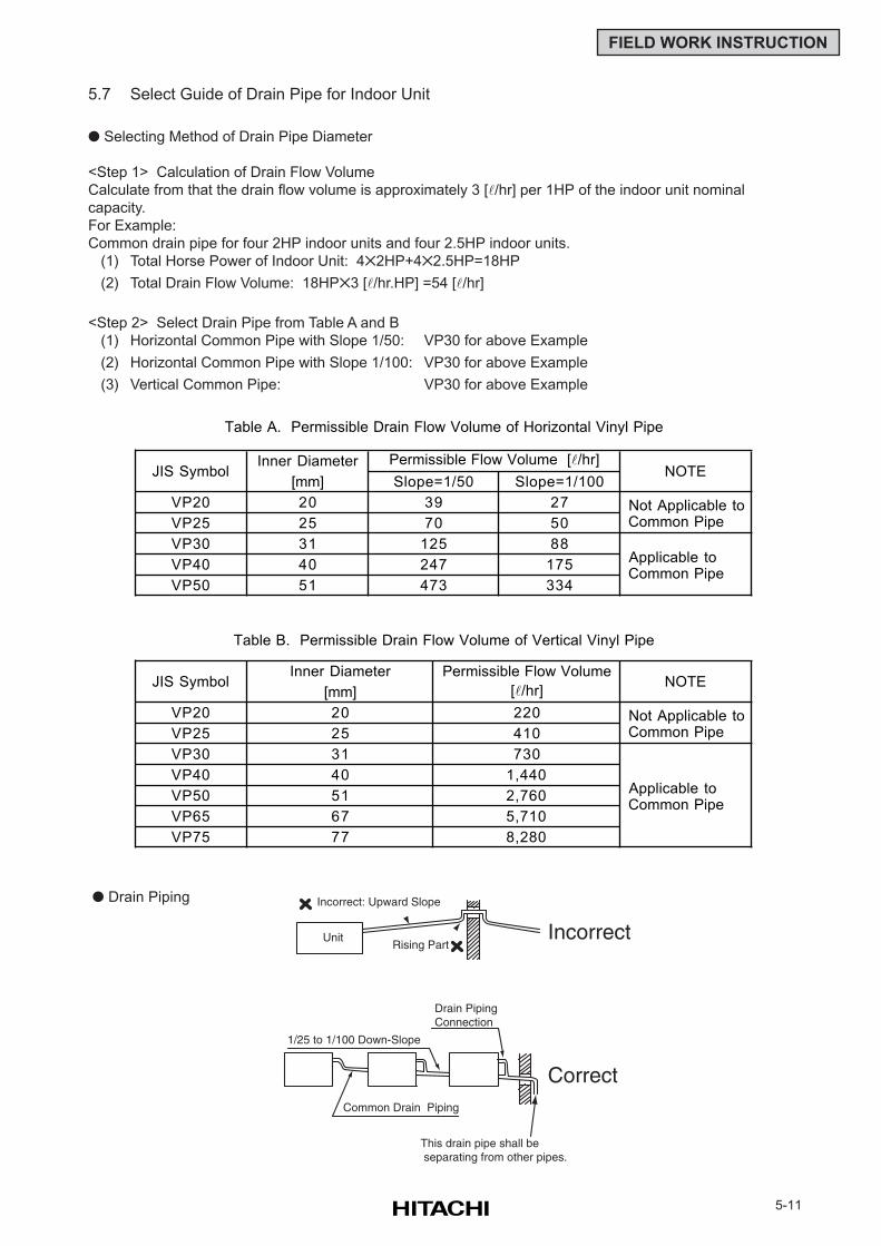
5-11
FIELD WORK INSTRUCTION
5.7 Select Guide of Drain Pipe for Indoor Unit
Selecting Method of Drain Pipe Diameter
<Step 1> Calculation of Drain Flow Volume
Calculate from that the drain flow volume is approximately 3 [l/hr] per 1HP of the indoor unit nominal
capacity.
For Example:
Common drain pipe for four 2HP indoor units and four 2.5HP indoor units.
(1) Total Horse Power of Indoor Unit: 42HP+42.5HP=18HP
(2) Total Drain Flow Volume: 18HP3 [l/hr.HP] =54 [l/hr]
<Step 2> Select Drain Pipe from Table A and B
(1) Horizontal Common Pipe with Slope 1/50: VP30 for above Example
(2) Horizontal Common Pipe with Slope 1/100: VP30 for above Example
(3) Vertical Common Pipe: VP30 for above Example
Drain Piping
Inner Diameter
[mm] Slope=1/100
VP20 20 27
VP25 25 50
VP30 31 88
VP40 40 175
VP50 51 334
VP20
VP25
VP30
VP40
VP50
VP65
VP75
Table A. Permissible Drain Flow Volume of Horizontal Vinyl Pipe
Table B. Permissible Drain Flow Volume of Vertical Vinyl Pipe
JIS Symbol
JIS Symbol
NOTE
NOTE
Applicable to Common Pipe
Not Applicable to Common Pipe
Permissible Flow Volume [l/hr]
5,710
8,280
2,760
Permissible Flow Volume
730
1,440
77
Slope=1/50
39
70
125
247
473
[l/hr]
220
410
Applicable to Common Pipe
Inner Diameter
[mm]
20
25
31
40
51
67
Not Applicable to Common Pipe
Drain PipingConnection
1/25 to 1/100 Down-Slope
Common Drain Piping
This drain pipe shall be separating from other pipes.
Incorrect: Upward Slope
UnitRising Part
Incorrect
Correct
5-12
FIELD WORK INSTRUCTION
5.8 Caution on Refrigerant Leakage
(1) Maximum Permissible Concentration of HCFC Gas
The refrigerant R407C (or R22), charged in the SET-FREE FSG, FS1/FS3, FS5 and FXG/FX3 system,
is an incombustible and non-toxic gas. However, if leakage occurs and gas fills a room, it may cause
suffocation.
The maximum permissible concentration of HCFC gas, R407C in air is 0.31 kg/m3, R22 in air is
0.3 kg/m3, according to the refrigeration and air conditioning facility standard (KHK S 0010) by the
KHK (High Pressure Gas Protection Association) Japan.
Therefore, some effective measure must be taken to lower the R407C or R22 concentration in air
below 0.3 kg/m3, in case of leakage.
(2) Calculation of Refrigerant Concentration
(a) Calculate the total quantity of refrigerant R (kg) charged in the system connecting all the indoor
units of rooms to be air conditioned.
(b) Calculate the room volume V (m3) of each objective room.
(c) Calculate the refrigerant concentration C (kg/m3) of the room according to the following equation.
(3) Countermeasure for Refrigerant Leakage According to KHK Standards
The facility shall be arranged as follows referring to the KHK standards, so that the refrigerant
concentration will be below 0.3 kg/m3.
(a) Provide a shutterless opening which will allow fresh air to circulate into the room.
(b) Provide a doorless opening of 0.15% or more size to the floor area.
(c) Provide a ventilator, linked with a gas leak detector, of 0.4 m3/min. or more ventilating capacity per
Japanese Refrigeration Ton (= compressor displacement m3/h / 8.5 (R22) or 9.8 (R407C)) of the air
conditioning system utilizing refrigerant R22.
<FSG, FSG1/FS3, FS5 Series>
RAS-5FSG ............................ 2.15 / 2.15 ton (50Hz / 60Hz)
RAS-5FS3............................. 2.48 / 2.48 ton
RAS-8FSG ............................ 3.74 / 3.98 ton
RAS-8FS3............................. 4.31 / 4.59 ton
RAS-10FSG .......................... 4.01 / 4.31 ton
RAS-10FS3 ........................... 4.63 / 4.97 ton
RAS-16FSG .......................... 5.78 / 6.44 ton
RAS-16FS3 ........................... 6.66 / 7.42 ton
RAS-20FSG .......................... 7.36 / 8.35 ton
RAS-20FS3 ........................... 8.49 / 9.63 ton
RAS-24FSG1 ........................ 8.72 / 9.96 ton
RAS-24FS5 ........................... 10.05 / 11.48 ton
RAS-30FSG1 ........................ 10.55 / 12.17 ton
RAS-30FS5 ........................... 12.16 / 14.03 ton
<FXG/FX3 Series>
RAS-8FXG ............................ 3.74 ton (50Hz)
RAS-8FX3............................. 4.31 ton
RAS-10FXG .......................... 4.01 ton
RAS-10FX3 ........................... 4.63 ton
(d) Pay a special attention to the place, such as a basement, etc., where refrigerant can stay, since
refrigerant is heavier than air.
R: Total Quantity of Charged Refrigerant (kg) = C: Refrigerant Concentration
V: Room Volume (m3) ≤ 0.3 (kg/m3)
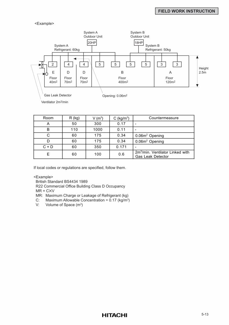
5-13
FIELD WORK INSTRUCTION
Room R (kg) V (m3) C (kg/m3) Countermeasure
A 50 300 0.17 -
B 110 1000 0.11 -
C 60 175 0.34 0.06m2 Opening
D 60 175 0.34 0.06m2 Opening
C + D 60 350 0.171 -
E 60 100 0.6 2m3/min. Ventilator Linked with Gas Leak Detector
If local codes or regulations are specified, follow them.
<Example>
British Standard BS4434 1989
R22 Commercial Office Building Class D Occupancy
MR = CV
MR: Maximum Charge or Leakage of Refrigerant (kg)
C: Maximum Allowable Concentration = 0.17 (kg/m3)
V: Volume of Space (m3)
<Example>
2 4 4 5 5 5 5 3 3
20HP 18HP
Height
2.5m
System A
Refrigerant: 60kg
System B
Refrigerant: 50kg
System A
Outdoor Unit
System B
Outdoor Unit
Floor
40m2
Floor
70m2
Floor
70m2
Floor
400m2
Floor
120m2
Opening: 0.06m2Gas Leak Detector
Ventilator 2m3/min
E D D B A
5-14
FIELD WORK INSTRUCTION
5.9 Maintenance Work
(1) For Indoor Unit and Outdoor Unit
(a) Fan and Fan Motor
Lubrication - All fan motors are pre-lubricated and sealed at the factory. Therefore, no lubricating
maintenance is required.
Sound and Vibration - Inspect for abnormal sound and vibration.
Rotation - Inspect for clockwise rotation and rotating speed.
Insulation - Inspect for electrical insulation resistance.
(b) Heat Exchanger
Clog - Inspect and remove any accumulated dirt and dust from the heat exchanger at regular
intervals. As for outdoor unit, other obstacles such as growing grass and pieces of paper, which
might restrict air flow, should also be removed.
(c) Piping Connection
Leakage - Inspect for refrigerant leakage at piping connection.
(d) Cabinet
Stain and Lubrication - Inspect and remove any stain and lubrication.
Fixing Screw - Inspect and fix loosened or lost screws.
Insulation - Inspect and repair peeled thermal insulation material on cabinet.
(e) Electrical Equipment
Activation - Inspect for abnormal activation of the magnetic contactor, auxiliary relay, PCB and
etc.
Line Condition - Pay attention to working voltage, amperage and phase balance. Inspect for
faulty contact caused by loosened terminal connections, oxidized contacts, foreign matter, and
other items. Inspect for electrical insulation resistance.
(f) Control and Protective Devices
Setting - Do not readjust the setting in the field unless the setting is maintained at a point other
than the point listed in “11. SAFETY AND CONTROL DEVICE SETTING” of “TCII”.
(2) For Indoor Unit
(a) Air Filter
Cleaning - Inspect and remove any accumulated dirt and dust according to “12.2 Filter Cleaning”
of “TCII”.
(b) Drain Pan, Drain-up Mechanism and Drain Pipe
Drain Line - Inspect and clean the condensate drain line at least twice a year.
Drain-up Mechanism - Inspect for activation of drain-up mechanism.
(c) Float Switch
Activation - Inspect for activation of float switch.
(3) For Outdoor Unit
(a) Compressor
Sound and Vibration - Inspect for abnormal sound and vibration.
Activation - Inspect for that the voltage drop of power supply line is within 16% at start and within
2% during operation.
(b) Reverse Valve
Activation - Inspect for any abnormal activating sound.
(c) Strainer
Clog - Inspect for that no temperature difference between both ends.
(d) Earth Wire
Earth Line - Inspect for continuity to the earth.
(e) Oil Heater
Activation - The oil heater should be activated at least 12 hours before start-up, by switching ON
the main power source.
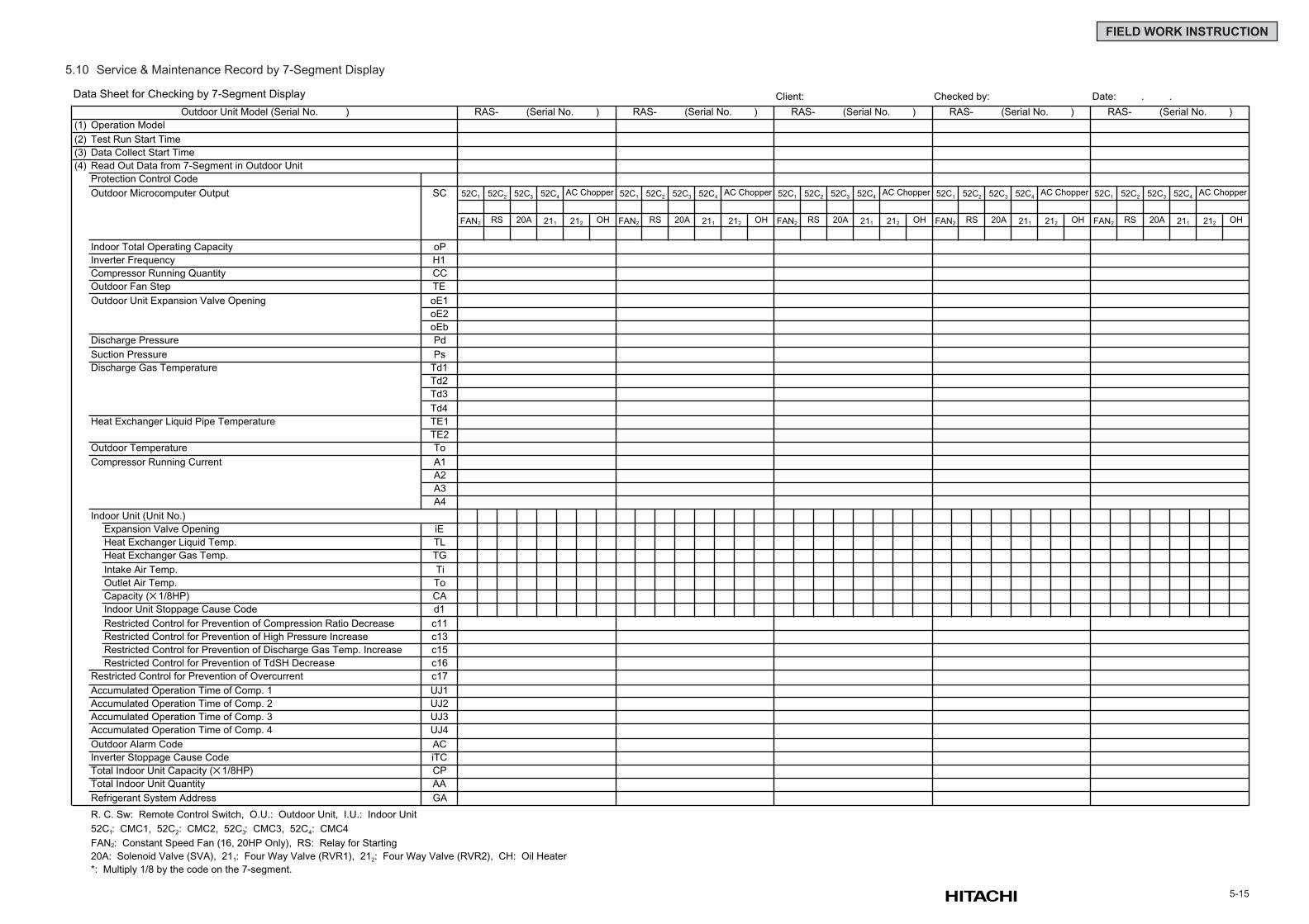
5-15
FIELD WORK INSTRUCTION
5.10 Service & Maintenance Record by 7-Segment Display
Data Sheet for Checking by 7-Segment Display Client: Checked by: Date: . .
Outdoor Unit Model (Serial No. ) RAS- (Serial No. ) RAS- (Serial No. ) RAS- (Serial No. ) RAS- (Serial No. ) RAS- (Serial No. )
(1) Operation Model
(2) Test Run Start Time
(3) Data Collect Start Time
(4) Read Out Data from 7-Segment in Outdoor Unit
Protection Control Code
Outdoor Microcomputer Output SC 52C1 52C2 52C3 52C4AC Chopper 52C1 52C2 52C3 52C4
AC Chopper 52C1 52C2 52C3 52C4AC Chopper 52C1 52C2 52C3 52C4
AC Chopper 52C1 52C2 52C3 52C4AC Chopper
FAN2 RS 20A 211 212 OH FAN2 RS 20A 211 212 OH FAN2 RS 20A 211 212 OH FAN2 RS 20A 211 212 OH FAN2 RS 20A 211 212 OH
Indoor Total Operating Capacity oP
Inverter Frequency H1
Compressor Running Quantity CC
Outdoor Fan Step TE
Outdoor Unit Expansion Valve Opening oE1
oE2
oEb
Discharge Pressure Pd
Suction Pressure Ps
Discharge Gas Temperature Td1
Td2
Td3
Td4
Heat Exchanger Liquid Pipe Temperature TE1
TE2
Outdoor Temperature To
Compressor Running Current A1
A2
A3
A4
Indoor Unit (Unit No.)
Expansion Valve Opening iE
Heat Exchanger Liquid Temp. TL
Heat Exchanger Gas Temp. TG
Intake Air Temp. Ti
Outlet Air Temp. To
Capacity (1/8HP) CA
Indoor Unit Stoppage Cause Code d1
Restricted Control for Prevention of Compression Ratio Decrease c11
Restricted Control for Prevention of High Pressure Increase c13
Restricted Control for Prevention of Discharge Gas Temp. Increase c15
Restricted Control for Prevention of TdSH Decrease c16
Restricted Control for Prevention of Overcurrent c17
Accumulated Operation Time of Comp. 1 UJ1
Accumulated Operation Time of Comp. 2 UJ2
Accumulated Operation Time of Comp. 3 UJ3
Accumulated Operation Time of Comp. 4 UJ4
Outdoor Alarm Code AC
Inverter Stoppage Cause Code iTC
Total Indoor Unit Capacity (1/8HP) CP
Total Indoor Unit Quantity AA
Refrigerant System Address GA
R. C. Sw: Remote Control Switch, O.U.: Outdoor Unit, I.U.: Indoor Unit
52C1: CMC1, 52C2: CMC2, 52C3: CMC3, 52C4: CMC4
FAN2: Constant Speed Fan (16, 20HP Only), RS: Relay for Starting
20A: Solenoid Valve (SVA), 211: Four Way Valve (RVR1), 212: Four Way Valve (RVR2), CH: Oil Heater
*: Multiply 1/8 by the code on the 7-segment.
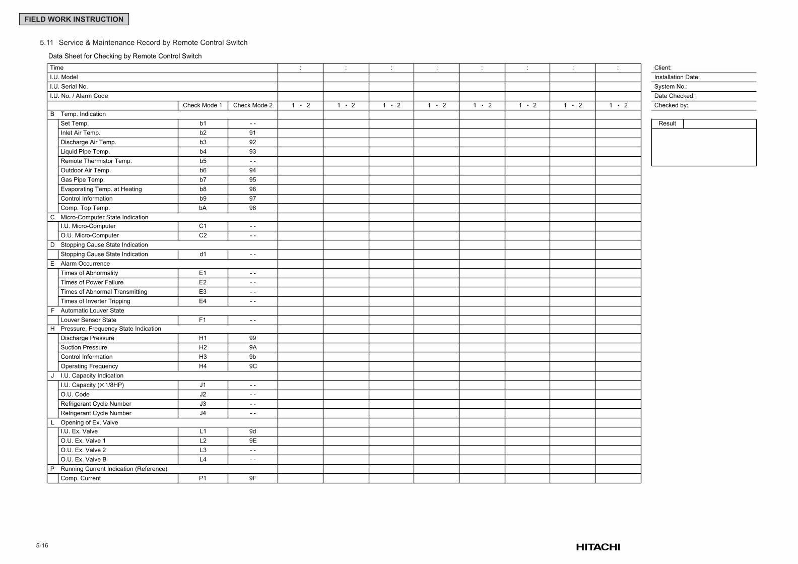
5-16
FIELD WORK INSTRUCTION
5.11 Service & Maintenance Record by Remote Control Switch
Data Sheet for Checking by Remote Control Switch
Time : : : : : : : : Client:
I.U. Model Installation Date:
I.U. Serial No. System No.:
I.U. No. / Alarm Code Date Checked:
Check Mode 1 Check Mode 2 1 2 1 2 1 2 1 2 1 2 1 2 1 2 1 2 Checked by:
B Temp. Indication
Set Temp. b1 - - Result
Inlet Air Temp. b2 91
Discharge Air Temp. b3 92
Liquid Pipe Temp. b4 93
Remote Thermistor Temp. b5 - -
Outdoor Air Temp. b6 94
Gas Pipe Temp. b7 95
Evaporating Temp. at Heating b8 96
Control Information b9 97
Comp. Top Temp. bA 98
C Micro-Computer State Indication
I.U. Micro-Computer C1 - -
O.U. Micro-Computer C2 - -
D Stopping Cause State Indication
Stopping Cause State Indication d1 - -
E Alarm Occurrence
Times of Abnormality E1 - -
Times of Power Failure E2 - -
Times of Abnormal Transmitting E3 - -
Times of Inverter Tripping E4 - -
F Automatic Louver State
Louver Sensor State F1 - -
H Pressure, Frequency State Indication
Discharge Pressure H1 99
Suction Pressure H2 9A
Control Information H3 9b
Operating Frequency H4 9C
J I.U. Capacity Indication
I.U. Capacity (1/8HP) J1 - -
O.U. Code J2 - -
Refrigerant Cycle Number J3 - -
Refrigerant Cycle Number J4 - -
L Opening of Ex. Valve
I.U. Ex. Valve L1 9d
O.U. Ex. Valve 1 L2 9E
O.U. Ex. Valve 2 L3 - -
O.U. Ex. Valve B L4 - -
P Running Current Indication (Reference)
Comp. Current P1 9F
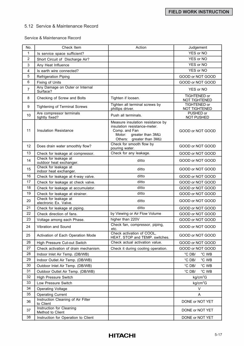
5-17
FIELD WORK INSTRUCTION
No. Check Item Action Judgement
1 Is service space sufficient? YES or NO
2 Short Circuit of Discharge Air? YES or NO
3 Any Heat Influence YES or NO
4 Is earth wire connected? YES or NO
5 Refrigeration Piping GOOD or NOT GOOD
6 Fixing of Units GOOD or NOT GOOD
7 Any Damage on Outer or Internal Surface?
YES or NO
8 Checking of Screw and Bolts Tighten if loosen.TIGHTENED or
NOT TIGHTENED
9 Tightening of Terminal Screws Tighten all terminal screws by phillips driver.
TIGHTENED orNOT TIGHTENED
10 Are compressor terminals tightly fixed?
Push all terminals.PUSHED or
NOT PUSHED
11 Insulation Resistance
Measure insulation resistance by insulation resistance-meter. Comp. and Fan Motor: greater than 3MΩ Others: greater than 3MΩ
GOOD or NOT GOOD
12 Does drain water smoothly flow? Check for smooth flow by pouring water.
GOOD or NOT GOOD
13 Check for leakage at compressor. Check for any leakage. GOOD or NOT GOOD
14 Check for leakage at outdoor heat exchanger.
ditto GOOD or NOT GOOD
15 Check for leakage at indoor heat exchanger.
ditto GOOD or NOT GOOD
16 Check for leakage at 4-way valve. ditto GOOD or NOT GOOD
17 Check for leakage at check valve. ditto GOOD or NOT GOOD
18 Check for leakage at accumulator. ditto GOOD or NOT GOOD
19 Check for leakage at strainer. ditto GOOD or NOT GOOD
20 Check for leakage at electronic Ex. Valve.
ditto GOOD or NOT GOOD
21 Check for leakage at piping. ditto GOOD or NOT GOOD
22 Check direction of fans. by Viewing or Air Flow Volume GOOD or NOT GOOD
23 Voltage among each Phase. higher than 220V GOOD or NOT GOOD
24 Vibration and Sound Check fan, compressor, piping, etc.
GOOD or NOT GOOD
25 Activation of Each Operation Mode Check activation of COOL, HEAT, STOP and TEMP. switches.
GOOD or NOT GOOD
26 High Pressure Cut-out Switch Check actual activation value. GOOD or NOT GOOD
27 Check activation of drain mechanism. Check it during cooling operation. GOOD or NOT GOOD
28 Indoor Inlet Air Temp. (DB/WB) oC DB/ oC WB
29 Indoor Outlet Air Temp. (DB/WB) oC DB/ oC WB
30 Outdoor Inlet Air Temp. (DB/WB) oC DB/ oC WB
31 Outdoor Outlet Air Temp. (DB/WB) oC DB/ oC WB
32 High Pressure Switch kg/cm2G
33 Low Pressure Switch kg/cm2G
34 Operating Voltage V
35 Operating Current A
36 Instruction Cleaning of Air Filter to Client
DONE or NOT YET
37 Instruction for Cleaning Method to Client
DONE or NOT YET
38 Instruction for Operation to Client DONE or NOT YET
5.12 Service & Maintenance Record
Service & Maintenance Record


Catalog No.5413553 2003 Printed in Japan (N)
Specifications in this catalog are subject to change without notice, in order that HITACHI may bring the latest innovations to their
customers.