Implementing MPLS Traffic Engineering
Multiprotocol Label Switching (MPLS) is a standards-based solution driven by the Internet EngineeringTask Force (IETF) that was devised to convert the Internet and IP backbones from best-effort networks intobusiness-class transport mediums.
MPLS, with its label switching capabilities, eliminates the need for an IP route look-up and creates a virtualcircuit (VC) switching function, allowing enterprises the same performance on their IP-based network servicesas with those delivered over traditional networks such as Frame Relay or Asynchronous Transfer Mode(ATM).
MPLS traffic engineering (MPLS-TE) software enables an MPLS backbone to replicate and expand uponthe TE capabilities of Layer 2 ATM and Frame Relay networks. MPLS is an integration of Layer 2 and Layer3 technologies. Bymaking traditional Layer 2 features available to Layer 3, MPLS enables traffic engineering.Thus, you can offer in a one-tier network what now can be achieved only by overlaying a Layer 3 networkon a Layer 2 network.
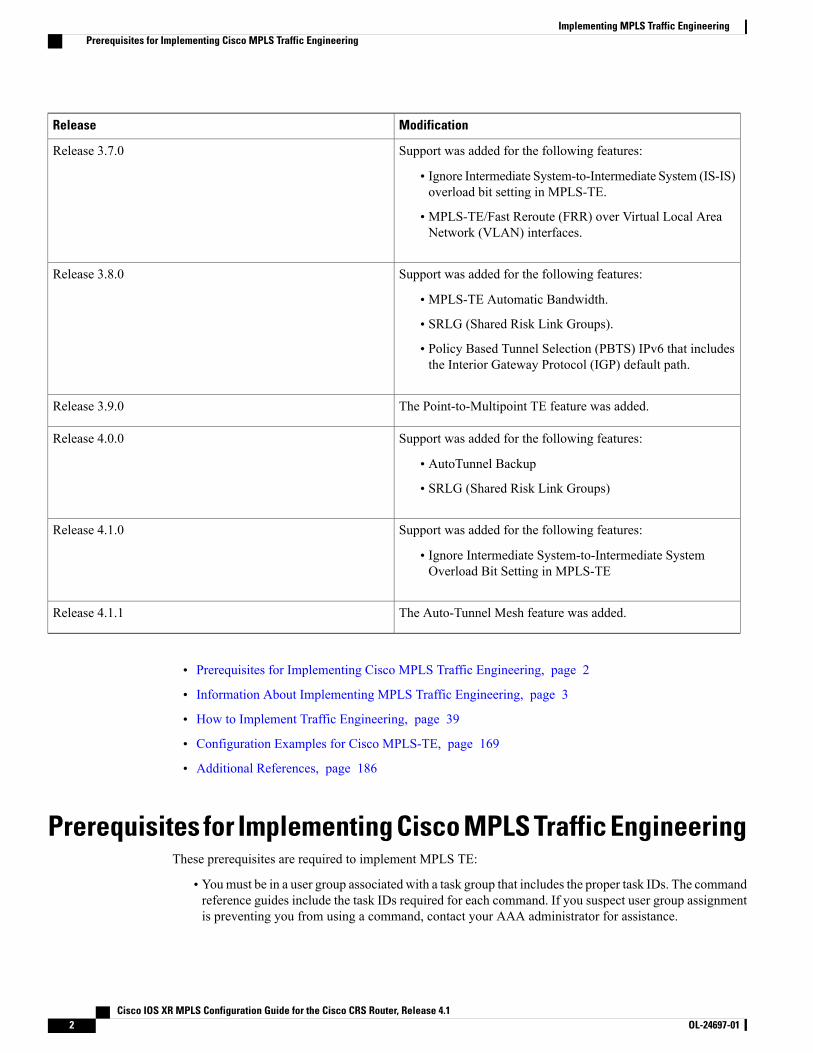
Feature History for Implementing MPLS-TE
ModificationRelease
This feature was introduced.Release 2.0
Support was added for Generalized MPLS.Release 3.3.0
Support was added for Flexible Name-based Tunnel Constraints,InterareaMPLS-TE,MPLS-TE Forwarding Adjacency, GMPLSProtection and Restoration, and GMPLS Path Protection.
Release 3.4.0
Support was added for MPLS-TE and fast reroute link bundling.Release 3.4.1
Support was added for Unequal Load Balancing, IS-IS IP FastReroute Loop-free Alternative routing functionality, and PathComputation Element (PCE).
Release 3.5.0
Cisco IOS XR MPLS Configuration Guide for the Cisco CRS Router, Release 4.1 OL-24697-01 1
ModificationRelease
Support was added for the following features:
• Ignore Intermediate System-to-Intermediate System (IS-IS)overload bit setting in MPLS-TE.
• MPLS-TE/Fast Reroute (FRR) over Virtual Local AreaNetwork (VLAN) interfaces.
Release 3.7.0
Support was added for the following features:
• MPLS-TE Automatic Bandwidth.
• SRLG (Shared Risk Link Groups).
• Policy Based Tunnel Selection (PBTS) IPv6 that includesthe Interior Gateway Protocol (IGP) default path.
Release 3.8.0
The Point-to-Multipoint TE feature was added.Release 3.9.0
Support was added for the following features:
• AutoTunnel Backup
• SRLG (Shared Risk Link Groups)
Release 4.0.0
Support was added for the following features:
• Ignore Intermediate System-to-Intermediate SystemOverload Bit Setting in MPLS-TE
Release 4.1.0
The Auto-Tunnel Mesh feature was added.Release 4.1.1
• Prerequisites for Implementing Cisco MPLS Traffic Engineering, page 2
• Information About Implementing MPLS Traffic Engineering, page 3
• How to Implement Traffic Engineering, page 39
• Configuration Examples for Cisco MPLS-TE, page 169
• Additional References, page 186
Prerequisites for Implementing Cisco MPLS Traffic EngineeringThese prerequisites are required to implement MPLS TE:
• Youmust be in a user group associated with a task group that includes the proper task IDs. The commandreference guides include the task IDs required for each command. If you suspect user group assignmentis preventing you from using a command, contact your AAA administrator for assistance.
Cisco IOS XR MPLS Configuration Guide for the Cisco CRS Router, Release 4.12 OL-24697-01
Implementing MPLS Traffic EngineeringPrerequisites for Implementing Cisco MPLS Traffic Engineering
• Router that runs Cisco IOS XR software .
• Installed composite mini-image and the MPLS package, or a full composite image.
• IGP activated.
• To configure Point-to-Multipoint (P2MP)-TE, a base set of RSVP and TE configuration parameters oningress, midpoint, and egress nodes in the MPLS network is required. In addition, Point-to-Point (P2P)parameters are required.
• Enable LDP globally by using the mpls ldp command to allocate local labels even in RSVP (MPLS TE)only core. You do not have to specify any interface if the core is LDP free.
Information About Implementing MPLS Traffic EngineeringTo implement MPLS-TE, you should understand these concepts:
Overview of MPLS Traffic EngineeringMPLS-TE software enables anMPLS backbone to replicate and expand upon the traffic engineering capabilitiesof Layer 2 ATM and Frame Relay networks. MPLS is an integration of Layer 2 and Layer 3 technologies.By making traditional Layer 2 features available to Layer 3, MPLS enables traffic engineering. Thus, you canoffer in a one-tier network what now can be achieved only by overlaying a Layer 3 network on a Layer 2network.
MPLS-TE is essential for service provider and Internet service provider (ISP) backbones. Such backbonesmust support a high use of transmission capacity, and the networks must be very resilient so that they canwithstand link or node failures.MPLS-TE provides an integrated approach to traffic engineering.WithMPLS,traffic engineering capabilities are integrated into Layer 3, which optimizes the routing of IP traffic, giventhe constraints imposed by backbone capacity and topology.
Related Topics
Configuring Forwarding over the MPLS-TE Tunnel, on page 45
Benefits of MPLS Traffic EngineeringMPLS-TE enables ISPs to route network traffic to offer the best service to their users in terms of throughputand delay. By making the service provider more efficient, traffic engineering reduces the cost of the network.
Currently, some ISPs base their services on an overlay model. In the overlay model, transmission facilitiesare managed by Layer 2 switching. The routers see only a fully meshed virtual topology, making mostdestinations appear one hop away. If you use the explicit Layer 2 transit layer, you can precisely control howtraffic uses available bandwidth. However, the overlaymodel has numerous disadvantages.MPLS-TE achievesthe TE benefits of the overlay model without running a separate network and without a non-scalable, fullmesh of router interconnects.
How MPLS-TE WorksMPLS-TE automatically establishes and maintains label switched paths (LSPs) across the backbone by usingRSVP. The path that an LSP uses is determined by the LSP resource requirements and network resources,
Cisco IOS XR MPLS Configuration Guide for the Cisco CRS Router, Release 4.1 OL-24697-01 3
Implementing MPLS Traffic EngineeringInformation About Implementing MPLS Traffic Engineering
such as bandwidth. Available resources are flooded by means of extensions to a link-state-based InteriorGateway Protocol (IGP).
MPLS-TE tunnels are calculated at the LSP headend router, based on a fit between the required and availableresources (constraint-based routing). The IGP automatically routes the traffic to these LSPs.
Typically, a packet crossing the MPLS-TE backbone travels on a single LSP that connects the ingress pointto the egress point. MPLS-TE is built on these mechanisms:
Tunnel interfaces
From a Layer 2 standpoint, anMPLS tunnel interface represents the headend of an LSP. It is configuredwith a set of resource requirements, such as bandwidth and media requirements, and priority. From aLayer 3 standpoint, an LSP tunnel interface is the headend of a unidirectional virtual link to the tunneldestination.
MPLS-TE path calculation module
This calculation module operates at the LSP headend. The module determines a path to use for an LSP.The path calculation uses a link-state database containing flooded topology and resource information.
RSVP with TE extensions
RSVP operates at each LSP hop and is used to signal and maintain LSPs based on the calculated path.
MPLS-TE link management module
This module operates at each LSP hop, performs link call admission on the RSVP signaling messages,and performs bookkeeping on topology and resource information to be flooded.
Link-state IGP (Intermediate System-to-Intermediate System [IS-IS] or Open Shortest Path First[OSPF]—each with traffic engineering extensions)
These IGPs are used to globally flood topology and resource information from the link managementmodule.
Enhancements to the shortest path first (SPF) calculation used by the link-state IGP (IS-IS or OSPF)
The IGP automatically routes traffic to the appropriate LSP tunnel, based on tunnel destination. Staticroutes can also be used to direct traffic to LSP tunnels.
Label switching forwarding
This forwarding mechanism provides routers with a Layer 2-like ability to direct traffic across multiplehops of the LSP established by RSVP signaling.
One approach to engineering a backbone is to define a mesh of tunnels from every ingress device to everyegress device. The MPLS-TE path calculation and signaling modules determine the path taken by the LSPsfor these tunnels, subject to resource availability and the dynamic state of the network.
The IGP (operating at an ingress device) determines which traffic should go to which egress device, and steersthat traffic into the tunnel from ingress to egress. A flow from an ingress device to an egress device might beso large that it cannot fit over a single link, so it cannot be carried by a single tunnel. In this case, multipletunnels between a given ingress and egress can be configured, and the flow is distributed using load sharingamong the tunnels.
Cisco IOS XR MPLS Configuration Guide for the Cisco CRS Router, Release 4.14 OL-24697-01
Implementing MPLS Traffic EngineeringOverview of MPLS Traffic Engineering
Related Topics
Building MPLS-TE Topology, on page 39Creating an MPLS-TE Tunnel, on page 42Build MPLS-TE Topology and Tunnels: Example, on page 169
MPLS Traffic EngineeringMultiprotocol Label Switching (MPLS) is an Internet Engineering Task Force (IETF)-specified frameworkthat provides efficient designation, routing, forwarding, and switching of traffic flows through the network.
TE is the process of adjusting bandwidth allocations to ensure that enough bandwidth is available forhigh-priority traffic.
InMPLS TE, the upstream router creates a network tunnel for a particular traffic stream and sets the bandwidthavailable for that tunnel.
Backup AutoTunnelsThe MPLS Traffic Engineering AutoTunnel Backup feature enables a router to dynamically build backuptunnels on the interfaces that are configured withMPLS TE tunnels. This feature enables a router to dynamicallybuild backup tunnels when they are needed. This prevents you from having to buildMPLSTE tunnels statically.
The MPLS Traffic Engineering (TE)—AutoTunnel Backup feature has these benefits:
• Backup tunnels are built automatically, eliminating the need for users to preconfigure each backup tunneland then assign the backup tunnel to the protected interface.
• Protection is expanded—FRR does not protect IP traffic that is not using the TE tunnel or LabelDistribution Protocol (LDP) labels that are not using the TE tunnel.
This feature protects against these failures:
• P2P Tunnel NHOP protection—Protects against link failure for the associated P2P protected tunnel
• P2P Tunnel NNHOP protection—Protects against node failure for the associated P2P protected tunnel
• P2MP Tunnel NHOP protection—Protects against link failure for the associated P2MP protectedtunnel
Related Topics
Enabling an AutoTunnel Backup, on page 53
Removing an AutoTunnel Backup, on page 54
Establishing MPLS Backup AutoTunnels to Protect Fast Reroutable TE LSPs, on page 56Establishing Next-Hop Tunnels with Link Protection, on page 57
Link Protection
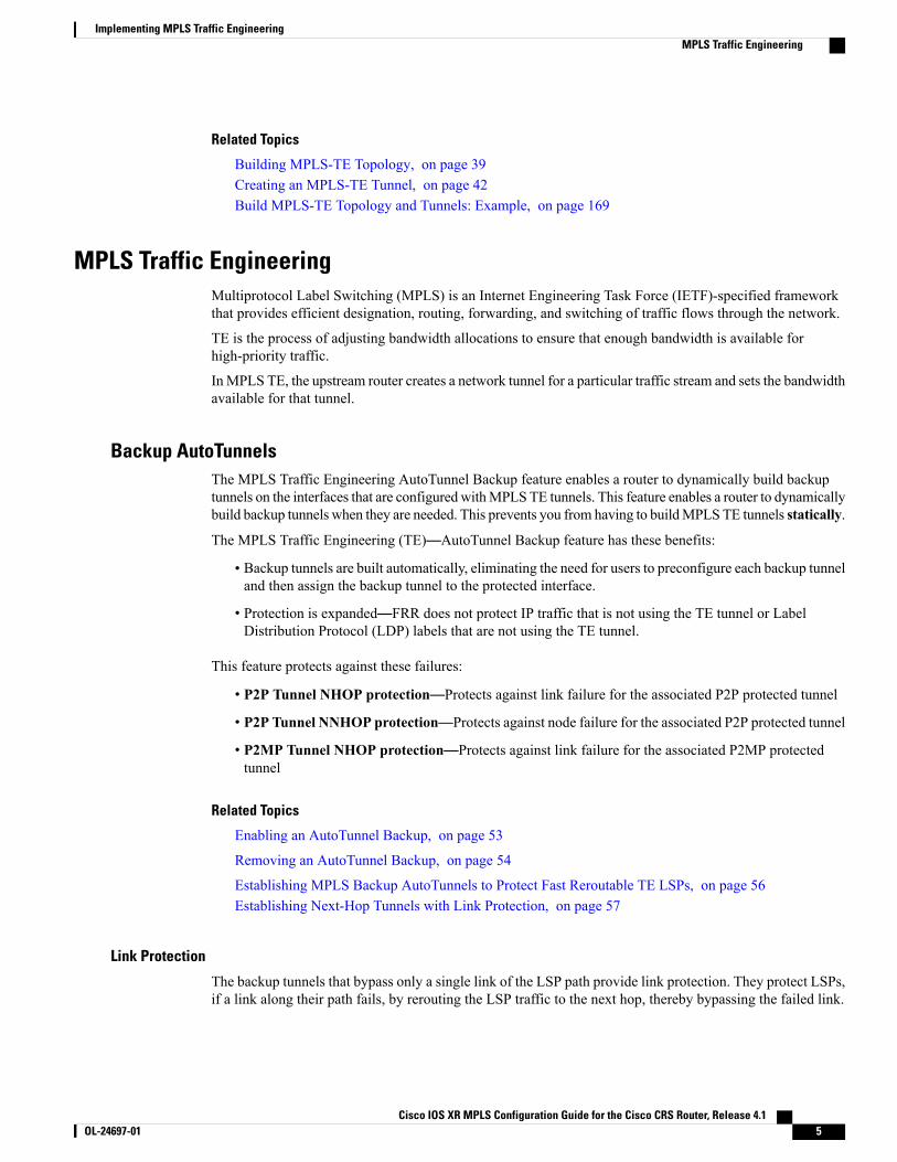
The backup tunnels that bypass only a single link of the LSP path provide link protection. They protect LSPs,if a link along their path fails, by rerouting the LSP traffic to the next hop, thereby bypassing the failed link.
Cisco IOS XR MPLS Configuration Guide for the Cisco CRS Router, Release 4.1 OL-24697-01 5
Implementing MPLS Traffic EngineeringMPLS Traffic Engineering
These are referred to as NHOP backup tunnels because they terminate at the LSP's next hop beyond the pointof failure.
This figure illustrates link protection.
Figure 1: Link Protection
Node Protection
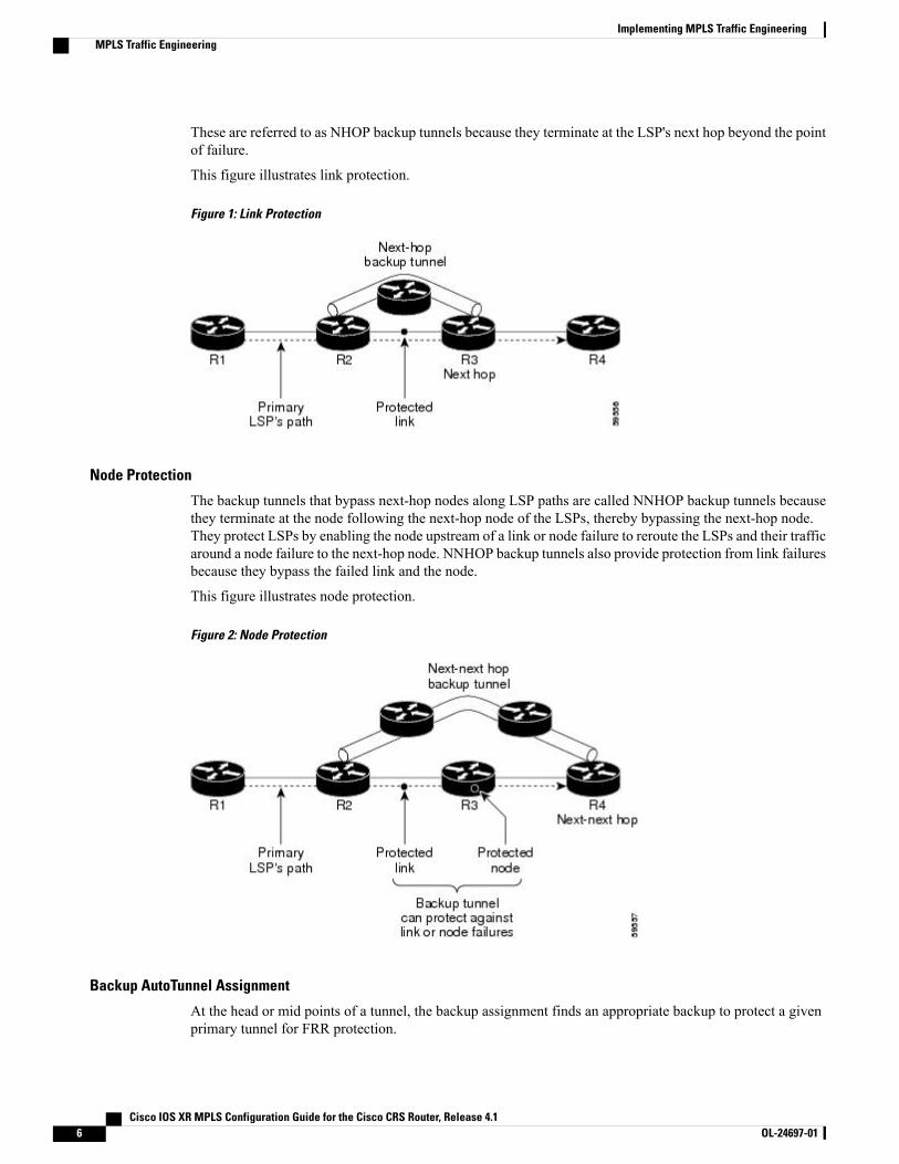
The backup tunnels that bypass next-hop nodes along LSP paths are called NNHOP backup tunnels becausethey terminate at the node following the next-hop node of the LSPs, thereby bypassing the next-hop node.They protect LSPs by enabling the node upstream of a link or node failure to reroute the LSPs and their trafficaround a node failure to the next-hop node. NNHOP backup tunnels also provide protection from link failuresbecause they bypass the failed link and the node.
This figure illustrates node protection.
Figure 2: Node Protection
Backup AutoTunnel Assignment
At the head or mid points of a tunnel, the backup assignment finds an appropriate backup to protect a givenprimary tunnel for FRR protection.
Cisco IOS XR MPLS Configuration Guide for the Cisco CRS Router, Release 4.16 OL-24697-01
Implementing MPLS Traffic EngineeringMPLS Traffic Engineering
The backup assignment logic is performed differently based on the type of backup configured on the outputinterface used by the primary tunnel. Configured backup types are:
• Static Backup
• AutoTunnel Backup
• No Backup (In this case no backup assignment is performed and the tunnels is unprotected.)
Static backup and Backup AutoTunnel cannot exist together on the same interface orlink.
Note
Node protection is always preferred over link protection in the Backup AutoTunnelassignment.
Note
In order that the Backup AutoTunnel feature operates successfully, the following configuration must be appliedat global configuration level:ipv4 unnumbered mpls traffic-eng Loopback 0
The Loopback 0 is used as router ID.Note
Explicit Paths
Explicit paths are used to create backup autotunnels as follows:
For NHOP Backup Autotunnels:
• NHOP excludes the protected link's local IP address.
• NHOP excludes the protected link’s remote IP address.
• The explicit-path name is _autob_nhop_tunnelxxx, where xxx matches the dynamically created backuptunnel ID.
For NNHOP Backup Autotunnels:
• NNHOP excludes the protected link’s local IP address.
• NNHOP excludes the protected link’s remote IP address (link address on next hop).
• NNHOP excludes the NHOP router ID of the protected primary tunnel next hop.
• The explicit-path name is _autob_nnhop_tunnelxxx, where xxx matches the dynamically created backuptunnel ID.
Periodic Backup PromotionThe periodic backup promotion attempts to find and assign a better backup for primary tunnels that are alreadyprotected.
Cisco IOS XR MPLS Configuration Guide for the Cisco CRS Router, Release 4.1 OL-24697-01 7
Implementing MPLS Traffic EngineeringMPLS Traffic Engineering
With AutoTunnel Backup, the only scenario where two backups can protect the same primary tunnel is whenboth an NHOP and NNHOP AutoTunnel Backups get created. The backup assignment takes place as soon asthe NHOP and NNHOP backup tunnels come up. So, there is no need to wait for the periodic promotion.
Although there is no exception for AutoTunnel Backups, periodic backup promotion has no impact on primarytunnels protected by AutoTunnel Backup.
One exception is when a manual promotion is triggered by the user using thempls traffic-eng fast-reroutetimers promotion command, where backup assignment or promotion is triggered on all FRR protected primarytunnels--even unprotected ones. This may trigger the immediate creation of some AutoTunnel Backup, if thecommand is entered within the time window when a required AutoTunnel Backup has not been yet created.
You can configure the periodic promotion timer using the global configurationmpls traffic-eng fast-reroutetimers promotion sec command. The range is 0 to 604800 seconds.
A value of 0 for the periodic promotion timer disables the periodic promotion.Note
Protocol-Based CLICisco IOS XR software provides a protocol-based command line interface. The CLI provides commands thatcan be used with the multiple IGP protocols supported by MPLS-TE.
Differentiated Services Traffic EngineeringMPLS Differentiated Services (Diff-Serv) Aware Traffic Engineering (DS-TE) is an extension of the regularMPLS-TE feature. Regular traffic engineering does not provide bandwidth guarantees to different trafficclasses. A single bandwidth constraint is used in regular TE that is shared by all traffic. To support variousclasses of service (CoS), users can configure multiple bandwidth constraints. These bandwidth constraintscan be treated differently based on the requirement for the traffic class using that constraint.
MPLSDS-TE provides the ability to configure multiple bandwidth constraints on anMPLS-enabled interface.Available bandwidths from all configured bandwidth constraints are advertised using IGP. TE tunnel isconfigured with bandwidth value and class-type requirements. Path calculation and admission control takethe bandwidth and class-type into consideration. RSVP is used to signal the TE tunnel with bandwidth andclass-type requirements.
MPLS DS-TE is deployed with either Russian Doll Model (RDM) or Maximum Allocation Model (MAM)for bandwidth calculations.
Cisco IOS XR software supports two DS-TE modes: Prestandard and IETF.
Related Topics
Confirming DiffServ-TE BandwidthBandwidth Configuration (MAM): ExampleBandwidth Configuration (RDM): Example
Cisco IOS XR MPLS Configuration Guide for the Cisco CRS Router, Release 4.18 OL-24697-01
Implementing MPLS Traffic EngineeringProtocol-Based CLI
Prestandard DS-TE ModePrestandard DS-TE uses the Cisco proprietary mechanisms for RSVP signaling and IGP advertisements. ThisDS-TEmode does not interoperate with third-party vendor equipment. Note that prestandard DS-TE is enabledonly after configuring the sub-pool bandwidth values on MPLS-enabled interfaces.
Prestandard Diff-Serve TE mode supports a single bandwidth constraint model a Russian Doll Model (RDM)with two bandwidth pools: global-pool and sub-pool.
TE class map is not used with Prestandard DS-TE mode.
Related Topics
Configuring a Prestandard DS-TE Tunnel, on page 59Configure IETF DS-TE Tunnels: Example, on page 170
IETF DS-TE ModeIETFDS-TEmode uses IETF-defined extensions for RSVP and IGP. This mode interoperates with third-partyvendor equipment.
IETF mode supports multiple bandwidth constraint models, including RDM and MAM, both with twobandwidth pools. In an IETF DS-TE network, identical bandwidth constraint models must be configured onall nodes.
TE class map is used with IETF DS-TE mode and must be configured the same way on all nodes in thenetwork.
Bandwidth Constraint ModelsIETF DS-TE mode provides support for the RDM and MAM bandwidth constraints models. Both modelssupport up to two bandwidth pools.
Cisco IOS XR software provides global configuration for the switching between bandwidth constraint models.Both models can be configured on a single interface to preconfigure the bandwidth constraints before swappingto an alternate bandwidth constraint model.
NSF is not guaranteed when you change the bandwidth constraint model or configuration information.Note
By default, RDM is the default bandwidth constraint model used in both pre-standard and IETF mode.
Maximum Allocation Bandwidth Constraint Model
The MAM constraint model has the following characteristics:
• Easy to use and intuitive.
• Isolation across class types.
• Simultaneously achieves isolation, bandwidth efficiency, and protection against QoS degradation.
Cisco IOS XR MPLS Configuration Guide for the Cisco CRS Router, Release 4.1 OL-24697-01 9
Implementing MPLS Traffic EngineeringDifferentiated Services Traffic Engineering
Related Topics
Configuring an IETF DS-TE Tunnel Using MAM, on page 65
Russian Doll Bandwidth Constraint Model
The RDM constraint model has these characteristics:
• Allows greater sharing of bandwidth among different class types.
• Ensures bandwidth efficiency simultaneously and protection against QoS degradation of all class types.
• Specifies that it is used in conjunction with preemption to simultaneously achieve isolation acrossclass-types such that each class-type is guaranteed its share of bandwidth, bandwidth efficiency, andprotection against QoS degradation of all class types.
We recommend that RDMnot be used in DS-TE environments in which the use of preemption is precluded.Although RDM ensures bandwidth efficiency and protection against QoS degradation of class types, itdoes guarantee isolation across class types.
Note
Related Topics
Configuring an IETF DS-TE Tunnel Using RDM, on page 62
TE Class MappingEach of the eight available bandwidth values advertised in the IGP corresponds to a TE class. Because theIGP advertises only eight bandwidth values, there can be a maximum of only eight TE classes supported inan IETF DS-TE network.
TE class mapping must be exactly the same on all routers in a DS-TE domain. It is the responsibility of theoperator configure these settings properly as there is no way to automatically check or enforce consistency.
The operator must configure TE tunnel class types and priority levels to form a valid TE class. When the TEclass map configuration is changed, tunnels already up are brought down. Tunnels in the down state, can beset up if a valid TE class map is found.
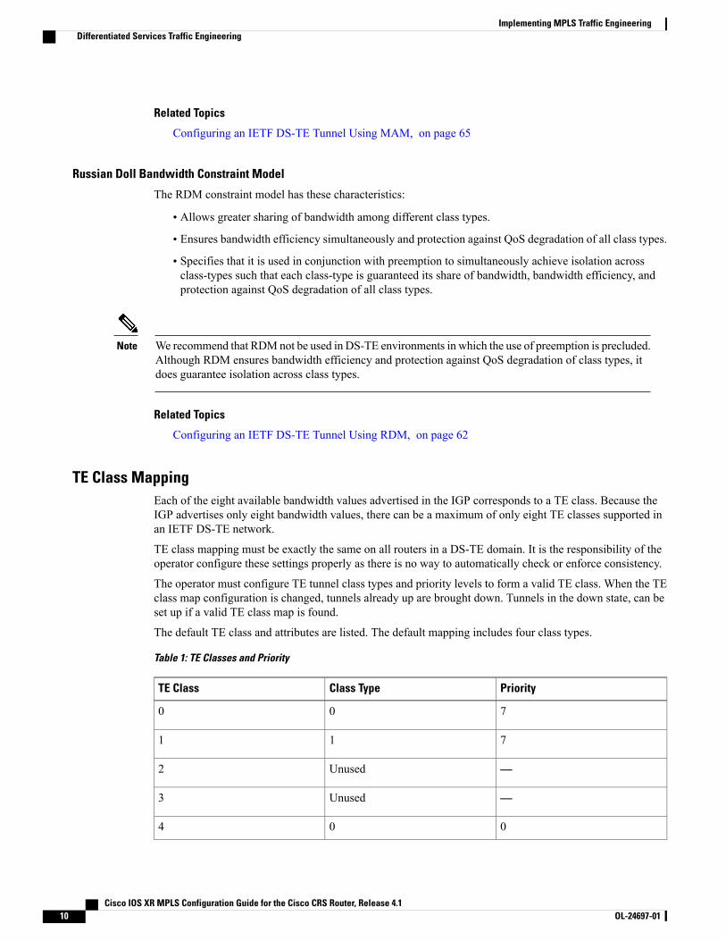
The default TE class and attributes are listed. The default mapping includes four class types.
Table 1: TE Classes and Priority
PriorityClass TypeTE Class
700
711
—Unused2
—Unused3
004
Cisco IOS XR MPLS Configuration Guide for the Cisco CRS Router, Release 4.110 OL-24697-01
Implementing MPLS Traffic EngineeringDifferentiated Services Traffic Engineering
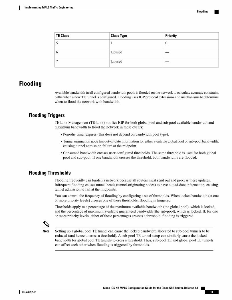
PriorityClass TypeTE Class
015
—Unused6
—Unused7
FloodingAvailable bandwidth in all configured bandwidth pools is flooded on the network to calculate accurate constraintpaths when a newTE tunnel is configured. Flooding uses IGP protocol extensions andmechanisms to determinewhen to flood the network with bandwidth.
Flooding TriggersTE Link Management (TE-Link) notifies IGP for both global pool and sub-pool available bandwidth andmaximum bandwidth to flood the network in these events:
• Periodic timer expires (this does not depend on bandwidth pool type).
• Tunnel origination node has out-of-date information for either available global pool or sub-pool bandwidth,causing tunnel admission failure at the midpoint.
• Consumed bandwidth crosses user-configured thresholds. The same threshold is used for both globalpool and sub-pool. If one bandwidth crosses the threshold, both bandwidths are flooded.
Flooding ThresholdsFlooding frequently can burden a network because all routers must send out and process these updates.Infrequent flooding causes tunnel heads (tunnel-originating nodes) to have out-of-date information, causingtunnel admission to fail at the midpoints.
You can control the frequency of flooding by configuring a set of thresholds. When locked bandwidth (at oneor more priority levels) crosses one of these thresholds, flooding is triggered.
Thresholds apply to a percentage of the maximum available bandwidth (the global pool), which is locked,and the percentage of maximum available guaranteed bandwidth (the sub-pool), which is locked. If, for oneor more priority levels, either of these percentages crosses a threshold, flooding is triggered.
Setting up a global pool TE tunnel can cause the locked bandwidth allocated to sub-pool tunnels to bereduced (and hence to cross a threshold). A sub-pool TE tunnel setup can similarly cause the lockedbandwidth for global pool TE tunnels to cross a threshold. Thus, sub-pool TE and global pool TE tunnelscan affect each other when flooding is triggered by thresholds.
Note
Cisco IOS XR MPLS Configuration Guide for the Cisco CRS Router, Release 4.1 OL-24697-01 11
Implementing MPLS Traffic EngineeringFlooding
Fast RerouteFast Reroute (FRR) provides link protection to LSPs enabling the traffic carried by LSPs that encounter afailed link to be rerouted around the failure. The reroute decision is controlled locally by the router connectedto the failed link. The headend router on the tunnel is notified of the link failure through IGP or through RSVP.When it is notified of a link failure, the headend router attempts to establish a new LSP that bypasses thefailure. This provides a path to reestablish links that fail, providing protection to data transfer.
FRR (link or node) is supported over sub-pool tunnels the same way as for regular TE tunnels. In particular,when link protection is activated for a given link, TE tunnels eligible for FRR are redirected into the protectionLSP, regardless of whether they are sub-pool or global pool tunnels.
The ability to configure FRR on a per-LSP basis makes it possible to provide different levels of fastrestoration to tunnels from different bandwidth pools.
Note
You should be aware of these requirements for the backup tunnel path:
• Backup tunnel must not pass through the element it protects.
• Primary tunnel and a backup tunnel should intersect at least at two points (nodes) on the path: point oflocal repair (PLR) and merge point (MP). PLR is the headend of the backup tunnel, andMP is the tailendof the backup tunnel.
When you configure TE tunnel with multiple protection on its path and merge point is the same node formore than one protection, you must configure record-route for that tunnel.
Note
Related Topics
Protecting MPLS Tunnels with Fast Reroute, on page 48
IS-IS IP Fast Reroute Loop-free AlternativeFor bandwidth protection, there must be sufficient backup bandwidth available to carry primary tunnel traffic.Use the ipfrr lfa command to compute loop-free alternates for all links or neighbors in the event of a link ornode failure. To enable node protection on broadcast links, IPRR and bidirectional forwarding detection (BFD)must be enabled on the interface under IS-IS.
MPLS FRR and IPFRR cannot be configured on the same interface at the same time.Note
For information about configuring BFD, see Cisco IOS XR Interface and Hardware Configuration Guide forthe Cisco CRS-1 Router.
Cisco IOS XR MPLS Configuration Guide for the Cisco CRS Router, Release 4.112 OL-24697-01
Implementing MPLS Traffic EngineeringFast Reroute
MPLS-TE and Fast Reroute over Link BundlesMPLS Traffic Engineering (TE) and Fast Reroute (FRR) are supported over bundle interfaces. MPLS-TE/FRRover virtual local area network (VLAN) interfaces is supported. Bidirectional forwarding detection (BFD)over VLAN is used as an FRR trigger to obtain less than 50 milliseconds of switchover time.
These link bundle types are supported for MPLS-TE/FRR:
• Over POS link bundles.
• Over Ethernet link bundles.
• Over VLANs over Ethernet link bundles.
• Number of links are limited to 100 for MPLS-TE and FRR.
• VLANs go over any Ethernet interface (for example, GigabitEthernet, TenGigE, and FastEthernet, soforth).
FRR is supported over bundle interfaces in the following ways:
• Uses minimum links as a threshold to trigger FRR over a bundle interface.
• Uses the minimum total available bandwidth as a threshold to trigger FRR.
Ignore Intermediate System-to-Intermediate System Overload Bit Setting inMPLS-TE
The Ignore Intermediate System-to-Intermediate System (IS-IS) overload bit avoidance feature allows networkadministrators to prevent RSVP-TE label switched paths (LSPs) from being disabled, when a router in thatpath has its Intermediate System-to-Intermediate System (IS-IS) overload bit set.
The IS-IS overload bit avoidance feature is activated using this command:mpls traffic-eng path-selection ignore overload
The IS-IS overload bit avoidance feature is deactivated using the no form of this command:no mpls traffic-eng path-selection ignore overload
When the IS-IS overload bit avoidance feature is activated, all nodes, including head nodes, mid nodes, andtail nodes, with the overload bit set, are ignored. This means that they are still available for use with RSVP-TElabel switched paths (LSPs). This feature enables you to include an overloaded node in CSPF.
Enhancement Options of IS-IS OLA
You can restrict configuring IS-IS overload bit avoidance with the following enhancement options:
• path-selection ignore overload head
The tunnels stay up if set-overload-bit is set by IS-IS on the head router. Ignores overload during CSPFfor LSPs originating from an overloaded node. In all other cases (mid, tail, or both), the tunnel staysdown.
• path-selection ignore overload mid
Cisco IOS XR MPLS Configuration Guide for the Cisco CRS Router, Release 4.1 OL-24697-01 13
Implementing MPLS Traffic EngineeringMPLS-TE and Fast Reroute over Link Bundles
The tunnels stay up if set-overload-bit is set by IS-IS on the mid router. Ignores overload during CSPFfor LSPs transiting from an overloaded node. In all other cases (head, tail, or both), the tunnel staysdown.
• path-selection ignore overload tail
The tunnels stay up if set-overload-bit is set by IS-IS on the tail router. Ignores overload during CSPFfor LSPs terminating at an overloaded node. In all other cases (head, mid, or both), the tunnel staysdown.
• path-selection ignore overload
The tunnels stay up irrespective of on which router the set-overload-bit is set by IS-IS.
When you do not select any of the options, including head nodes, mid nodes, and tailnodes, you get a behavior that is applicable to all nodes. This behavior is backwardcompatible in nature.
Note
For more information related to IS-IS overload avoidance related commands, see Cisco IOS XR MPLSCommand Reference for the Cisco CRS Router.
Related Topics
Configuring the Ignore Integrated IS-IS Overload Bit Setting in MPLS-TE, on page 70Configure the Ignore IS-IS Overload Bit Setting in MPLS-TE: Example, on page 171
DWDM Transponder IntegrationAGMPLS UNI based solution preserves all the advantages of the integration of the DWDM transponder intothe router blade. These advantages include:
• improved CAPEX and OPEX models
• component, space and power savings
• improved IP availability through pro-active protection.
GMPLS BenefitsGMPLS bridges the IP and photonic layers, therebymaking possible interoperable and scalable parallel growthin the IP and photonic dimensions.
This allows for rapid service deployment and operational efficiencies, as well as for increased revenueopportunities. A smooth transition becomes possible from a traditional segregated transport and service overlaymodel to a more unified peer model.
By streamlining support for multiplexing and switching in a hierarchical fashion, and by utilizing the flexibleintelligence of MPLS-TE, optical switching GMPLS becomes very helpful for service providers wanting tomanage large volumes of traffic in a cost-efficient manner.
Cisco IOS XR MPLS Configuration Guide for the Cisco CRS Router, Release 4.114 OL-24697-01
Implementing MPLS Traffic EngineeringDWDM Transponder Integration
GMPLS SupportGMPLS-TE provides support for:
• Open Shortest Path First (OSPF) for bidirectional TE tunnel
• Frame, lambda, and port (fiber) labels
• Numbered or Unnumbered links
• OSPF extensions–Route computation with optical constraints
• RSVP extensions–Graceful Restart
• Graceful deletion
• LSP hierarchy
• Peer model
• Border model Control plane separation
• Interarea or AS-Verbatim
• BGP4 or MPLS
• Restoration–Dynamic path computation
• Control channel manager
• Link summary
• Protection and restoration
Related Topics
Configuring Router IDs, on page 72Configuring OSPF over IPCC, on page 74
GMPLS Protection and RestorationGMPLS provides protection against failed channels (or links) between two adjacent nodes (span protection)and end-to-end dedicated protection (path protection). After the route is computed, signaling to establish thebackup paths is carried out through RSVP-TE or CR-LDP. For span protection, 1+1 orM:N protection schemesare provided by establishing secondary paths through the network. In addition, you can use signaling messagesto switch from the failed primary path to the secondary path.
Only 1:1 end-to-end path protection is supported.Note
The restoration of a failed path refers to the dynamic establishment of a backup path. This process requiresthe dynamic allocation of resources and route calculation. The following restoration methods are described:
• Line restoration—Finds an alternate route at an intermediate node.
• Path restoration—Initiates at the source node to route around a failed path within the path for a specificLSP.
Cisco IOS XR MPLS Configuration Guide for the Cisco CRS Router, Release 4.1 OL-24697-01 15
Implementing MPLS Traffic EngineeringDWDM Transponder Integration
Restoration schemes provide more bandwidth usage, because they do not preallocate any resource for an LSP.
GMPLS combines MPLS-FRR and other types of protection, such as SONET/SDH and wavelength.
In addition to SONET alarms in POS links, protection and restoration is also triggered by bidirectionalforwarding detection (BFD).
1:1 LSP Protection
When one specific protecting LSP or span protects one specific working LSP or span, 1:1 protection schemeoccurs. However, normal traffic is transmitted only over one LSP at a time for working or recovery.
1:1 protection with extra traffic refers to the scheme in which extra traffic is carried over a protecting LSPwhen the protecting LSP is not being used for the recovery of normal traffic. For example, the protecting LSPis in standby mode. When the protecting LSP is required to recover normal traffic from the failed workingLSP, the extra traffic is preempted. Extra traffic is not protected, but it can be restored. Extra traffic istransported using the protected LSP resources.
Shared Mesh Restoration and M:N Path Protection
Both shared mesh restoration and M:N (1:N is more practical) path protection offers sharing for protectionresources for multiple working LSPs. For 1:N protection, a specific protecting LSP is dedicated to the protectionof up to N working LSPs and spans. Shared mesh is defined as preplanned LSP rerouting, which reduces therestoration resource requirements by allowing multiple restoration LSPs to be initiated from distinct ingressnodes to share common resources, such as links and nodes.
End-to-end Recovery
End-to-end recovery refers to an entire LSP from the source for an ingress router endpoint to the destinationfor an egress router endpoint.
GMPLS Protection Requirements
The GMPLS protection requirements are specific to the protection scheme that is enabled at the data plane.For example, SONET APS or MPLS-FRR are identified as the data level for GMPLS protection.
GMPLS PrerequisitesThe following prerequisites are required to implement GMPLS on Cisco IOS XR software:
• You must be in a user group associated with a task group that includes the proper task IDs for GMPLScommands.
• Router that runs Cisco IOS XR software.
• Installation of the Cisco IOS XR softwaremini-image on the router.
Flexible Name-based Tunnel ConstraintsMPLS-TE Flexible Name-based Tunnel Constraints provides a simplified and more flexible means ofconfiguring link attributes and path affinities to compute paths for MPLS-TE tunnels.
Cisco IOS XR MPLS Configuration Guide for the Cisco CRS Router, Release 4.116 OL-24697-01
Implementing MPLS Traffic EngineeringFlexible Name-based Tunnel Constraints
In the traditional TE scheme, links are configured with attribute-flags that are flooded with TE link-stateparameters using Interior Gateway Protocols (IGPs), such as Open Shortest Path First (OSPF).
MPLS-TE Flexible Name-based Tunnel Constraints lets you assign, or map, up to 32 color names for affinityand attribute-flag attributes instead of 32-bit hexadecimal numbers. After mappings are defined, the attributescan be referred to by the corresponding color name in the command-line interface (CLI). Furthermore, youcan define constraints using include, include-strict, exclude, and exclude-all arguments, where each statementcan contain up to 10 colors, and define include constraints in both loose and strict sense.
You can configure affinity constraints using attribute flags or the Flexible Name Based Tunnel Constraintsscheme; however, when configurations for both schemes exist, only the configuration pertaining to thenew scheme is applied.
Note
Related Topics
Assigning Color Names to Numeric Values, on page 103Associating Affinity-Names with TE Links, on page 104Associating Affinity Constraints for TE Tunnels, on page 106Configure Flexible Name-based Tunnel Constraints: Example, on page 174
MPLS Traffic Engineering Interarea TunnelingThese topics describe the following new extensions of MPLS-TE:
• Interarea Support, on page 17
• Multiarea Support, on page 18
• Loose Hop Expansion, on page 19
• Loose Hop Reoptimization, on page 19
• Fast Reroute Node Protection, on page 19
Interarea SupportThe MPLS-TE interarea tunneling feature allows you to establish P2P tunnels spanning multiple InteriorGateway Protocol (IGP) areas and levels, thereby eliminating the requirement that headend and tailend routersreside in a single area.
Interarea support allows the configuration of a TE LSP that spans multiple areas, where its headend and tailendlabel switched routers (LSRs) reside in different IGP areas.
Multiarea and Interarea TE are required by the customers running multiple IGP area backbones (primarilyfor scalability reasons). This lets you limit the amount of flooded information, reduces the SPF duration, andlessens the impact of a link or node failure within an area, particularly with large WAN backbones split inmultiple areas.
Cisco IOS XR MPLS Configuration Guide for the Cisco CRS Router, Release 4.1 OL-24697-01 17
Implementing MPLS Traffic EngineeringMPLS Traffic Engineering Interarea Tunneling
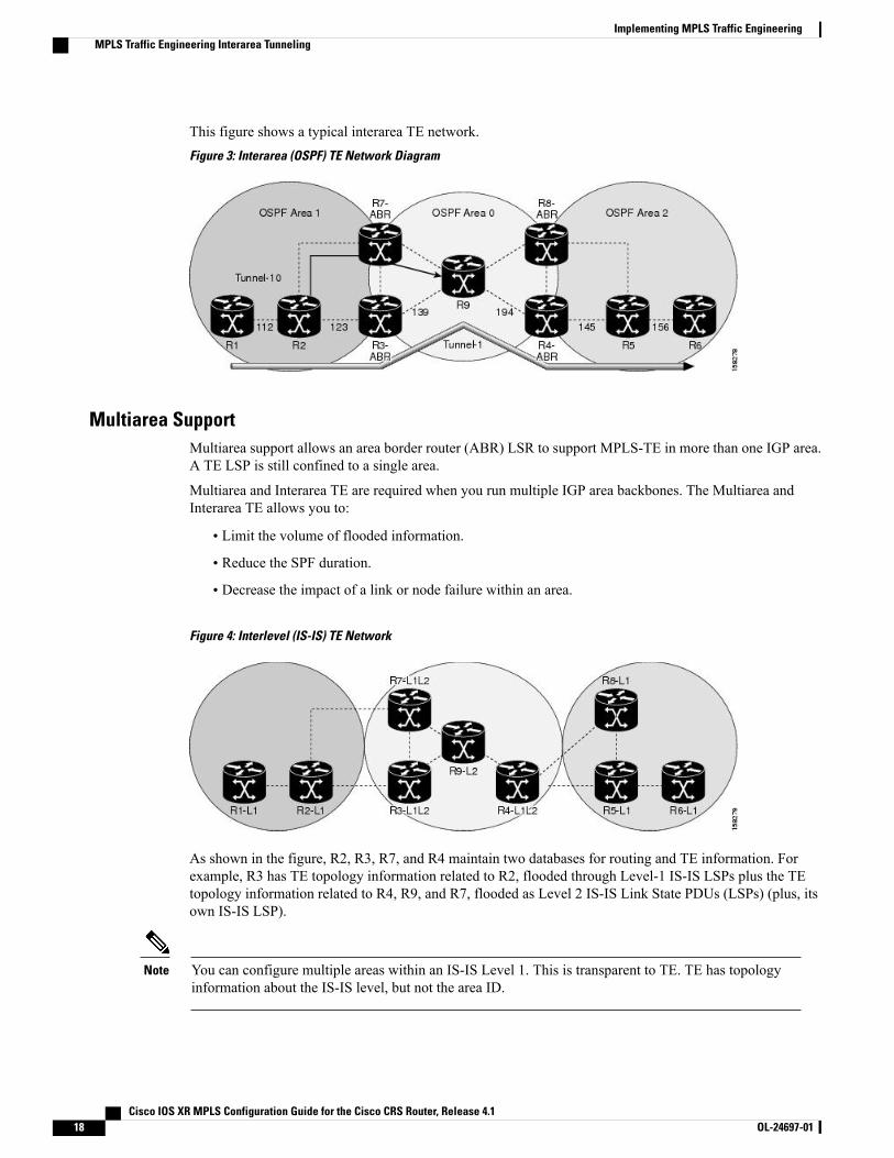
This figure shows a typical interarea TE network.Figure 3: Interarea (OSPF) TE Network Diagram
Multiarea SupportMultiarea support allows an area border router (ABR) LSR to support MPLS-TE in more than one IGP area.A TE LSP is still confined to a single area.
Multiarea and Interarea TE are required when you run multiple IGP area backbones. The Multiarea andInterarea TE allows you to:
• Limit the volume of flooded information.
• Reduce the SPF duration.
• Decrease the impact of a link or node failure within an area.
Figure 4: Interlevel (IS-IS) TE Network
As shown in the figure, R2, R3, R7, and R4 maintain two databases for routing and TE information. Forexample, R3 has TE topology information related to R2, flooded through Level-1 IS-IS LSPs plus the TEtopology information related to R4, R9, and R7, flooded as Level 2 IS-IS Link State PDUs (LSPs) (plus, itsown IS-IS LSP).
You can configure multiple areas within an IS-IS Level 1. This is transparent to TE. TE has topologyinformation about the IS-IS level, but not the area ID.
Note
Cisco IOS XR MPLS Configuration Guide for the Cisco CRS Router, Release 4.118 OL-24697-01
Implementing MPLS Traffic EngineeringMPLS Traffic Engineering Interarea Tunneling
Loose Hop ExpansionLoose hop optimization allows the reoptimization of tunnels spanning multiple areas and solves the problemwhich occurs when an MPLS-TE LSP traverses hops that are not in the LSP's headend's OSPF area and IS-ISlevel.
Interarea MPLS-TE allows you to configure an interarea traffic engineering (TE) label switched path (LSP)by specifying a loose source route of ABRs along the path. It is the then the responsibility of the ABR (havinga complete view of both areas) to find a path obeying the TE LSP constraints within the next area to reachthe next hop ABR (as specified on the headend). The same operation is performed by the last ABR connectedto the tailend area to reach the tailend LSR.
You must be aware of these considerations when using loose hop optimization:
• You must specify the router ID of the ABR node (as opposed to a link address on the ABR).
•When multiarea is deployed in a network that contains subareas, you must enable MPLS-TE in thesubarea for TE to find a path when loose hop is specified.
• You must specify the reachable explicit path for the interarea tunnel.
Loose Hop ReoptimizationLoose hop reoptimization allows the reoptimization of the tunnels spanning multiple areas and solves theproblem which occurs when an MPLS-TE headend does not have visibility into other IGP areas.
Whenever the headend attempts to reoptimize a tunnel, it tries to find a better path to the ABR in the headendarea. If a better path is found then the headend initiates the setup of a new LSP. In case a suitable path is notfound in the headend area, the headend initiates a querying message. The purpose of this message is to querythe ABRs in the areas other than the headend area to check if there exist any better paths in those areas. Thepurpose of this message is to query the ABRs in the areas other than the headend area, to check if a betterpath exists. If a better path does not exist, ABR forwards the query to the next router downstream. Alternatively,if better path is found, ABR responds with a special Path Error to the headend to indicate the existence of abetter path outside the headend area. Upon receiving the Path Error that indicates the existence of a betterpath, the headend router initiates the reoptimization.
ABR Node ProtectionBecause one IGP area does not have visibility into another IGP area, it is not possible to assign backup toprotect ABR node. To overcome this problem, node ID sub-object is added into the record route object of theprimary tunnel so that at a PLR node, backup destination address can be checked against primary tunnelrecord-route object and assign a backup tunnel.
Fast Reroute Node ProtectionIf a link failure occurs within an area, the upstream router directly connected to the failed link generates anRSVP path error message to the headend. As a response to the message, the headend sends an RSVP pathtear message and the corresponding path option is marked as invalid for a specified period and the nextpath-option (if any) is evaluated.
Cisco IOS XR MPLS Configuration Guide for the Cisco CRS Router, Release 4.1 OL-24697-01 19
Implementing MPLS Traffic EngineeringMPLS Traffic Engineering Interarea Tunneling
To retry the ABR immediately, a second path option (identical to the first one) should be configured.Alternatively, the retry period (path-option hold-down, 2 minutes by default) can be tuned to achieve a fasterretry.
Related Topics
Protecting MPLS Tunnels with Fast Reroute, on page 48
MPLS-TE Forwarding AdjacencyThe MPLS-TE Forwarding Adjacency feature allows a network administrator to handle a traffic engineering,label-switched path (LSP) tunnel as a link in an Interior Gateway Protocol (IGP) network based on the ShortestPath First (SPF) algorithm. A forwarding adjacency can be created between routers regardless of their locationin the network.
MPLS-TE Forwarding Adjacency BenefitsTE tunnel interfaces are advertised in the IGP network just like any other links. Routers can then use theseadvertisements in their IGPs to compute the SPF even if they are not the head end of any TE tunnels.
Related Topics
Configuring MPLS-TE Forwarding Adjacency, on page 113Configure Forwarding Adjacency: Example, on page 176
MPLS-TE Forwarding Adjacency RestrictionsThe following restrictions are listed for the MPLS-TE Forwarding Adjacency feature:
• Using theMPLS-TE Forwarding Adjacency feature increases the size of the IGP database by advertisinga TE tunnel as a link.
• The MPLS-TE Forwarding Adjacency feature is supported by Intermediate System-to-IntermediateSystem (IS-IS).
•When the MPLS-TE Forwarding Adjacency feature is enabled on a TE tunnel, the link is advertised inthe IGP network as a Type-Length-Value (TLV) 22 without any TE sub-TLV.
• MPLS-TE forwarding adjacency tunnels must be configured bidirectionally.
MPLS-TE Forwarding Adjacency PrerequisitesYour network must support the following features before enabling the MPLS -TE Forwarding Adjacencyfeature:
• MPLS
• IP Cisco Express Forwarding
• Intermediate System-to-Intermediate System (IS-IS)
Cisco IOS XR MPLS Configuration Guide for the Cisco CRS Router, Release 4.120 OL-24697-01
Implementing MPLS Traffic EngineeringMPLS-TE Forwarding Adjacency
Unequal Load BalancingUnequal load balancing permits the routing of unequal proportions of traffic through tunnels to a commondestination. Load shares on tunnels to the same destination are determined by TE from the tunnel configurationand passed through the MPLS Label Switching Database (LSD) to the Forwarding Information Base (FIB).
Load share values are renormalized by the FIB using values suitable for use by the forwarding code. Theexact traffic ratios observed may not, therefore, exactly mirror the configured traffic ratios. This effect ismore pronounced if there are many parallel tunnels to a destination, or if the load shares assigned to thosetunnels are very different. The exact renormalization algorithm used is platform-dependent.
Note
There are two ways to configure load balancing:
Explicit configuration
Using this method, load shares are explicitly configured on each tunnel.
Bandwidth configuration
If a tunnel is not configured with load-sharing parameters, the tunnel bandwidth and load-share valuesare considered equivalent for load-share calculations between tunnels, and a direct comparison betweenbandwidth and load-share configuration values is calculated.
Load shares are not dependent on any configuration other than the load share and bandwidth configuredon the tunnel and the state of the global configuration switch.
Note
Related Topics
Setting Unequal Load Balancing Parameters, on page 115Enabling Unequal Load Balancing, on page 117Configure Unequal Load Balancing: Example, on page 176
Path Computation ElementPath Computation Element (PCE) solves the specific issue of inter-domain path computation for MPLS-TElabel switched path (LSPs), when the head-end router does not possess full network topology information(for example, when the head-end and tail-end routers of an LSP reside in different IGP areas).
PCE uses area border routers (ABRs) to compute a TE LSP spanningmultiple IGP areas as well as computationof Inter-AS TE LSP.
PCE is usually used to define an overall architecture, which is made of several components, as follows:
Path Computation Element (PCE)
Represents a software module (which can be a component or application) that enables the router tocompute paths applying a set of constraints between any pair of nodes within the router’s TE topologydatabase. PCEs are discovered through IGP.
Cisco IOS XR MPLS Configuration Guide for the Cisco CRS Router, Release 4.1 OL-24697-01 21
Implementing MPLS Traffic EngineeringUnequal Load Balancing
Path Computation Client (PCC)
Represents a software module running on a router that is capable of sending and receiving pathcomputation requests and responses to and from PCEs. The PCC is typically an LSR (Label SwitchingRouter).
PCC-PCE communication protocol (PCEP)
Specifies that PCEP is a TCP-based protocol defined by the IETF PCEWG, and defines a set of messagesand objects used to manage PCEP sessions and to request and send paths for multi-domain TE LSPs.PCEP is used for communication between PCC and PCE (as well as between two PCEs) and employsIGP extensions to dynamically discover PCE.
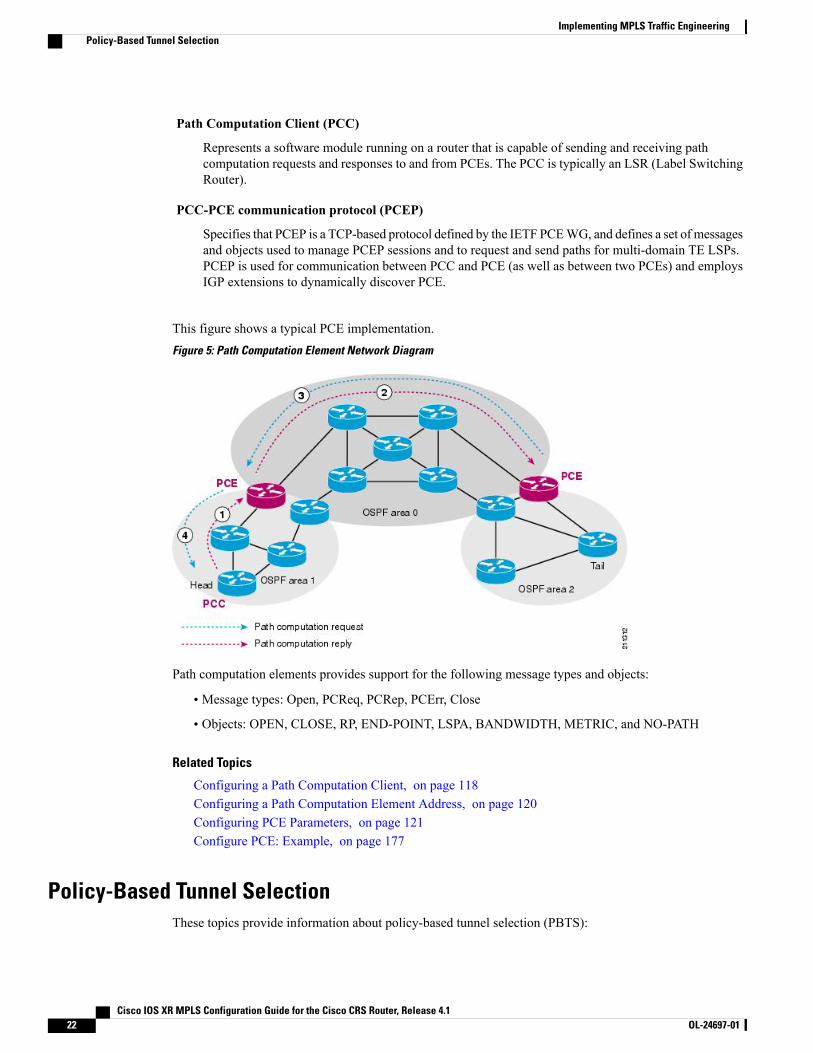
This figure shows a typical PCE implementation.Figure 5: Path Computation Element Network Diagram
Path computation elements provides support for the following message types and objects:
• Message types: Open, PCReq, PCRep, PCErr, Close
• Objects: OPEN, CLOSE, RP, END-POINT, LSPA, BANDWIDTH, METRIC, and NO-PATH
Related Topics
Configuring a Path Computation Client, on page 118Configuring a Path Computation Element Address, on page 120Configuring PCE Parameters, on page 121Configure PCE: Example, on page 177
Policy-Based Tunnel SelectionThese topics provide information about policy-based tunnel selection (PBTS):
Cisco IOS XR MPLS Configuration Guide for the Cisco CRS Router, Release 4.122 OL-24697-01
Implementing MPLS Traffic EngineeringPolicy-Based Tunnel Selection
• Policy-Based Tunnel Selection Overview, on page 23
• Policy-Based Tunnel Selection Functions, on page 23
• PBTS Restrictions, on page 24
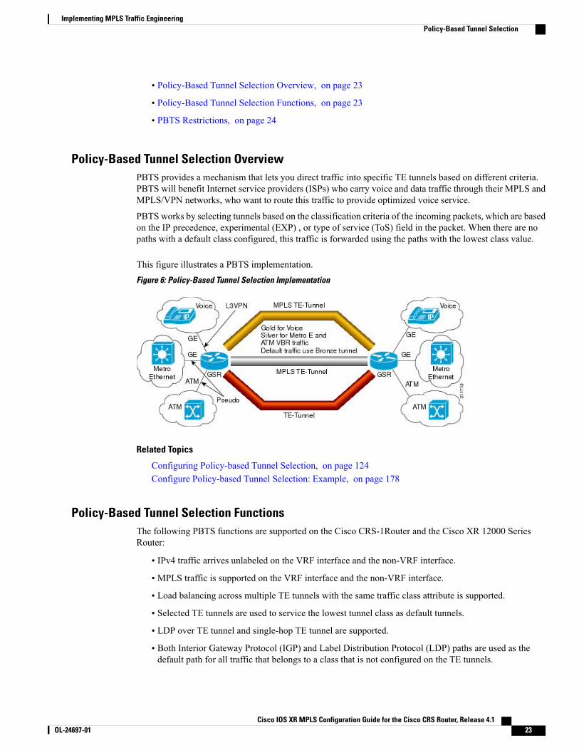
Policy-Based Tunnel Selection OverviewPBTS provides a mechanism that lets you direct traffic into specific TE tunnels based on different criteria.PBTS will benefit Internet service providers (ISPs) who carry voice and data traffic through their MPLS andMPLS/VPN networks, who want to route this traffic to provide optimized voice service.
PBTS works by selecting tunnels based on the classification criteria of the incoming packets, which are basedon the IP precedence, experimental (EXP) , or type of service (ToS) field in the packet. When there are nopaths with a default class configured, this traffic is forwarded using the paths with the lowest class value.
This figure illustrates a PBTS implementation.Figure 6: Policy-Based Tunnel Selection Implementation
Related Topics
Configuring Policy-based Tunnel Selection, on page 124Configure Policy-based Tunnel Selection: Example, on page 178
Policy-Based Tunnel Selection FunctionsThe following PBTS functions are supported on the Cisco CRS-1Router and the Cisco XR 12000 SeriesRouter:
• IPv4 traffic arrives unlabeled on the VRF interface and the non-VRF interface.
• MPLS traffic is supported on the VRF interface and the non-VRF interface.
• Load balancing across multiple TE tunnels with the same traffic class attribute is supported.
• Selected TE tunnels are used to service the lowest tunnel class as default tunnels.
• LDP over TE tunnel and single-hop TE tunnel are supported.
• Both Interior Gateway Protocol (IGP) and Label Distribution Protocol (LDP) paths are used as thedefault path for all traffic that belongs to a class that is not configured on the TE tunnels.
Cisco IOS XR MPLS Configuration Guide for the Cisco CRS Router, Release 4.1 OL-24697-01 23
Implementing MPLS Traffic EngineeringPolicy-Based Tunnel Selection
The following PBTS functions are supported on the Cisco CRS-1Router and the Cisco XR 12000 SeriesRouter:
• L2VPN preferred path selection lets traffic be directed to a particular TE tunnel.
• According to the quality-of-service (QoS) policy, tunnel selection is based on the outgoing experimental(EXP) value and the remarked EXP value.
• IPv6 traffic for both 6VPE and 6PE scenarios are supported.
Related Topics
Configuring Policy-based Tunnel Selection, on page 124Configure Policy-based Tunnel Selection: Example, on page 178
PBTS RestrictionsWhen implementing PBTS, the following restrictions are listed:
•When you enable QoS EXP remarking on an interface, the EXP value is used to determine the egresstunnel interface, not the incoming EXP value.
• Egress-side remarking does not affect PBTS tunnel selection.
• For information about the PBTS default path behavior and thempls traffic-eng igp-intact (OSPF)command or mpls traffic-eng igp-intact (IS-IS) command, see Cisco IOS XR Routing CommandReference for the Cisco CRS Router.
Path ProtectionPath protection provides an end-to-end failure recoverymechanism (that is, a full path protection) forMPLS-TEtunnels. A secondary Label Switched Path (LSP) is established, in advance, to provide failure protection forthe protected LSP that is carrying a tunnel's TE traffic. When there is a failure on the protected LSP, the sourcerouter immediately enables the secondary LSP to temporarily carry the tunnel's traffic. If there is a failure onthe secondary LSP, the tunnel no longer has path protection until the failure along the secondary path iscleared. Path protection can be used within a single area (OSPF or IS-IS), external BGP [eBGP], and staticroutes.
The failure detection mechanisms triggers a switchover to a secondary tunnel by:
• Path error or resv-tear from Resource Reservation Protocol (RSVP) signaling
• Notification from the Bidirectional Forwarding Detection (BFD) protocol that a neighbor is lost
• Notification from the Interior Gateway Protocol (IGP) that the adjacency is down
• Local teardown of the protected tunnel's LSP due to preemption in order to signal higher priority LSPs,a Packet over SONET (POS) alarm, online insertion and removal (OIR), and so on
An alternate recovery mechanism is Fast Reroute (FRR), which protects MPLS-TE LSPs only from link andnode failures, by locally repairing the LSPs at the point of failure.
Although not as fast as link or node protection, presignaling a secondary LSP is faster than configuring asecondary primary path option, or allowing the tunnel's source router to dynamically recalculate a path. The
Cisco IOS XR MPLS Configuration Guide for the Cisco CRS Router, Release 4.124 OL-24697-01
Implementing MPLS Traffic EngineeringPath Protection
actual recovery time is topology-dependent, and affected by delay factors such as propagation delay or switchfabric latency.
Related Topics
Configure Tunnels for Path Protection: Example, on page 178
Pre-requisites for Path ProtectionThese are the pre-requisites for enabling path protection:
• Ensure that your network supports MPLS-TE, Cisco Express Forwarding, and IntermediateSystem-to-Intermediate System (IS-IS) or Open Shortest Path First (OSPF).
• Enable MPLS.
• Configure TE on the routers.
• Configure a TE tunnel with a dynamic path option by using the path-option command with thedynamic keyword.
Related Topics
Configure Tunnels for Path Protection: Example, on page 178
Restrictions for Path Protection• Only Point-to-Point (P2P) tunnels are supported.
• Point-to-Multipoint (P2MP) TE tunnels are not supported.
• A maximum of one standby LSP is supported.
• There can be only one secondary path for each dynamic path option.
• Explicit path option can be configured for the path protected TE with the secondary path option asdynamic.
• Do not use link and node protection with path protection on the headend router.
• A maximum number of path protected tunnel TE heads is 2000.
• A maximum number of TE tunnel heads is equal to 4000.
Related Topics
Configure Tunnels for Path Protection: Example, on page 178
MPLS-TE Automatic BandwidthThe MPLS-TE automatic bandwidth feature measures the traffic in a tunnel and periodically adjusts thesignaled bandwidth for the tunnel.
These topics provide information about MPLS-TE automatic bandwidth:
Cisco IOS XR MPLS Configuration Guide for the Cisco CRS Router, Release 4.1 OL-24697-01 25
Implementing MPLS Traffic EngineeringMPLS-TE Automatic Bandwidth
MPLS-TE Automatic Bandwidth OverviewMPLS-TE automatic bandwidth is configured on individual Label Switched Paths (LSPs) at every head-end.MPLS-TE monitors the traffic rate on a tunnel interface. Periodically, MPLS-TE resizes the bandwidth onthe tunnel interface to align it closely with the traffic in the tunnel. MPLS-TE automatic bandwidth can performthese functions:
• Monitors periodic polling of the tunnel output rate
• Resizes the tunnel bandwidth by adjusting the highest rate observed during a given period
For every traffic-engineered tunnel that is configured for an automatic bandwidth, the average output rate issampled, based on various configurable parameters. Then, the tunnel bandwidth is readjusted automaticallybased upon either the largest average output rate that was noticed during a certain interval, or a configuredmaximum bandwidth value.
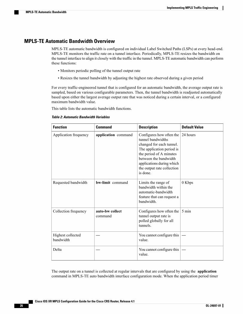
This table lists the automatic bandwidth functions.
Table 2: Automatic Bandwidth Variables
Default ValueDescriptionCommandFunction
24 hoursConfigures how often thetunnel bandwidthschanged for each tunnel.The application period isthe period of A minutesbetween the bandwidthapplications during whichthe output rate collectionis done.
application commandApplication frequency
0 KbpsLimits the range ofbandwidth within theautomatic-bandwidthfeature that can request abandwidth.
bw-limit commandRequested bandwidth
5 minConfigures how often thetunnel output rate ispolled globally for alltunnels.
auto-bw collectcommand
Collection frequency
—You cannot configure thisvalue.
—Highest collectedbandwidth
—You cannot configure thisvalue.
—Delta
The output rate on a tunnel is collected at regular intervals that are configured by using the applicationcommand in MPLS-TE auto bandwidth interface configuration mode. When the application period timer
Cisco IOS XR MPLS Configuration Guide for the Cisco CRS Router, Release 4.126 OL-24697-01
Implementing MPLS Traffic EngineeringMPLS-TE Automatic Bandwidth
expires, and when the difference between the measured and the current bandwidth exceeds the adjustmentthreshold, the tunnel is reoptimized. Then, the bandwidth samples are cleared to record the new largest outputrate at the next interval.
When reoptimizing the LSP with the new bandwidth, a new path request is generated. If the new bandwidthis not available, the last good LSP continues to be used. This way, the network experiences no trafficinterruptions.
If minimum or maximum bandwidth values are configured for a tunnel, the bandwidth, which the automaticbandwidth signals, stays within these values.
When more than 100 tunnels are auto-bw enabled, the algorithm will jitter the first application of everytunnel by a maximum of 20% (max 1hour). The algorithm does this to avoid too many tunnels runningauto bandwidth applications at the same time.
Note
If a tunnel is shut down, and is later brought again, the adjusted bandwidth is lost and the tunnel is broughtback with the initial configured bandwidth. In addition, the application period is reset when the tunnel isbrought back.
Related Topics
Configuring the Collection Frequency, on page 127Configuring the Automatic Bandwidth Functions, on page 129Configure Automatic Bandwidth: Example, on page 178
Adjustment ThresholdAdjustment Threshold is defined as a percentage of the current tunnel bandwidth and an absolute (minimum)bandwidth. Both thresholds must be fulfilled for the automatic bandwidth to resignal the tunnel. The tunnelbandwidth is resized only if the difference between the largest sample output rate and the current tunnelbandwidth is larger than the adjustment thresholds.
For example, assume that the automatic bandwidth is enabled on a tunnel in which the highest observedbandwidth B is 30 Mbps. Also, assume that the tunnel was initially configured for 45 Mbps. Therefore, thedifference is 15 mbit/s. Now, assuming the default adjustment thresholds of 10% and 10kbps, the tunnel issignalled with 30 Mbps when the application timer expires. This is because 10% of 45Mbit/s is 4.5 Mbit/s,which is smaller than 15 Mbit/s. The absolute threshold, which by default is 10kbps, is also crossed.
Overflow DetectionOverflow detection is used if a bandwidth must be resized as soon as an overflow condition is detected, withouthaving to wait for the expiry of an automatic bandwidth application frequency interval.
For overflow detection one configures a limit N, a percentage threshold Y% and optionally, a minimumbandwidth threshold Z. The percentage threshold is defined as the percentage of the actual signalled tunnelbandwidth. When the difference between the measured bandwidth and the actual bandwidth are both largerthan Y% and Z threshold, for N consecutive times, then the system triggers an overflow detection.
The bandwidth adjustment by the overflow detection is triggered only by an increase of traffic volume throughthe tunnel, and not by a decrease in the traffic volume. When you trigger an overflow detection, the automaticbandwidth application interval is reset.
By default, the overflow detection is disabled and needs to be manually configured.
Cisco IOS XR MPLS Configuration Guide for the Cisco CRS Router, Release 4.1 OL-24697-01 27
Implementing MPLS Traffic EngineeringMPLS-TE Automatic Bandwidth
Restrictions for MPLS-TE Automatic BandwidthWhen the automatic bandwidth cannot update the tunnel bandwidth, the following restrictions are listed:
• Tunnel is in a fast reroute (FRR) backup, active, or path protect active state. This occurs because of theassumption that protection is a temporary state, and there is no need to reserve the bandwidth on a backuptunnel. You should prevent taking away the bandwidth from other primary or backup tunnels.
• Reoptimization fails to occur during a lockdown. In this case, the automatic bandwidth does not updatethe bandwidth unless the bandwidth application is manually triggered by using the mpls traffic-engauto-bw apply command in EXEC mode.
Related Topics
Forcing the Current Application Period to Expire Immediately, on page 129
Point-to-Multipoint Traffic-Engineering
Point-to-Multipoint Traffic-Engineering OverviewThe Point-to-Multipoint (P2MP) Resource Reservation Protocol-Traffic Engineering (RSVP-TE) solutionallows service providers to implement IP multicast applications, such as IPTV and real-time video, broadcastover the MPLS label switch network. The RSVP-TE protocol is extended to signal point-to-point (P2P) andP2MP label switched paths (LSPs) across the MPLS and GMPLS networks.
By using RSVP-TE extensions as defined in RFC 4875, multiple subLSPs are signaled for a given TE source.The P2MP tunnel is considered as a set of Source-to-Leaf (S2L) subLSPs that connect the TE source tomultiple leaf Provider Edge (PE) nodes.
At the TE source, the ingress point of the P2MP-TE tunnel, IP multicast traffic is encapsulated with a uniqueMPLS label, which is associated with the P2MP-TE tunnel. The traffic continues to be label-switched in theP2MP tree. If needed, the labeled packet is replicated at branch nodes along the P2MP tree. When the labeledpacket reaches the egress leaf (PE) node, the MPLS label is removed and forwarded onto the IP multicast treeacross the PE-CE link.
To enable end-to-end IP multicast connectivity, RSVP is used in the MPLS-core for P2MP-TE signaling andPIM is used for PE-CE link signaling.
• All edge routers are running PIM-SSM or Source-SpecificMulticast (SSM) to exchangemulticast routinginformation with the directly-connected Customer Edge (CE) routers.
• In the MPLS network, RSVP P2MP-TE replaces PIM as the tree building mechanism, RSVP-TE graftsor prunes a given P2MP tree when the end-points are added or removed in the TE source configuration(explicit user operation).
These are the definitions for Point-to-Multipoint (P2MP) tunnels:
Source
Configures the node in which Label Switched Path (LSP) signaling is initiated.
Cisco IOS XR MPLS Configuration Guide for the Cisco CRS Router, Release 4.128 OL-24697-01
Implementing MPLS Traffic EngineeringPoint-to-Multipoint Traffic-Engineering
Mid-point
Specifies the transit node in which LSP signaling is processed (for example, not a source or receiver).
Receiver, Leaf, and Destination
Specifies the node in which LSP signaling ends.
Branch Point
Specifies the node in which packet replication is performed.
Source-to-Leaf (S2L) SubLSP
Specifies the P2MP-TE LSP segment that runs from the source to one leaf.
Point-to-Multipoint Traffic-Engineering Features
• P2MP RSVP-TE (RFC 4875) is supported. RFC 4875 is based on nonaggregate signaling; for example,per S2L signaling. Only P2MP LSP is supported.
• interface tunnel-mte command identifies the P2MP interface type.
• P2MP tunnel setup is supported with label replication.
• Fast-Reroute (FRR) protection is supported with sub-50 msec for traffic loss.
• Explicit routing is supported by using under utilized links.
• Reoptimization is supported by calculating a better set of paths to the destination with no traffic loss.
Per-S2L reoptimization is not supported.Note
• IPv4 and IPv6 payloads are supported.
• IPv4 and IPv6 multicast forwarding are supported on a P2MP tunnel interface through a static IGMPand MLD group configuration.
• Both IP multicast and P2MP Label SwitchMulticast (LSM) coexist in the same network; therefore, bothuse the same forwarding plane (LFIB or MPLS Forwarding Infrastructure [MFI]).
• P2MP label replication supports only Source-Specific Multicast (SSM) traffic. SSM configurationsupports the default value, none.
• Static mapping for multicast groups to the P2MP-TE tunnel is required.
Point-to-Multipoint Traffic-Engineering Benefits
• Single point of traffic control ensures that signaling and path engineering parameters (for example,protection and diversity) are configured only at the TE source node.
• Ability to configure explicit paths to enable optimized traffic distribution and prevention of single pointof failures in the network.
• Link protection of MPLS-labeled traffic traversing branch paths of the P2MP-TE tree.
Cisco IOS XR MPLS Configuration Guide for the Cisco CRS Router, Release 4.1 OL-24697-01 29
Implementing MPLS Traffic EngineeringPoint-to-Multipoint Traffic-Engineering
• Ability to do bandwidth Admission Control (AC) during set up and signaling of P2MP-TE paths in theMPLS network.
Related Topics
Enabling Multicast Routing on the Router, on page 146
Configure Point-to-Multipoint for the Source: Example, on page 181
Configure the Point-to-Multipoint Solution: Example, on page 183
Disabling Destinations, on page 154
Disable a Destination: Example, on page 182
Logging Per Destinations for Point-to-Multipoint , on page 157
Configure the Point-to-Multipoint Tunnel: Example, on page 182
Configure the Point-to-Multipoint Solution: Example, on page 183
Point-to-Multipoint RSVP-TE , on page 30
Path Option for Point-to-Multipoint RSVP-TE, on page 32
Point-to-Multipoint RSVP-TERSVP-TE signals a P2MP tunnel base that is based on a manual configuration. If all Source-to-Leaf (S2L)suse an explicit path, the P2MP tunnel creates a static tree that follows a predefined path based on a constraintsuch as a deterministic Label Switched Path (LSP). If the S2L uses a dynamic path, RSVP-TE creates a P2MPtunnel base on the best path in the RSVP-TE topology. RSVP-TE supports bandwidth reservation forconstraint-based routing.
When an explicit path option is used, specify both the local and peer IP addresses in the explicit path option,provided the link is a GigabitEthernet or a TenGigE based interface. For point-to-point links like POS orbundle POS, it is sufficient to mention the remote or peer IP address in the explicit path option.
RSVP-TE distributes stream information in which the topology tree does not change often (where the sourceand receivers are). For example, large scale video distribution between major sites is suitable for a subset ofmulticast applications. Because multicast traffic is already in the tunnel, the RSVP-TE tree is protected aslong as you build a backup path.
Fast-Reroute (FRR) capability is supported for P2MP RSVP-TE by using the unicast link protection. Youcan choose the type of traffic to go to the backup link.
The P2MP tunnel is applicable for all TE Tunnel destination (IntraArea, InterArea or InterAS).
The P2MP tunnel is signaled by the dynamic and explicit path option in the IGP intra area. Only interAreaand interAS, which are used for the P2MP tunnels, are signaled by the verbatim path option.
Related Topics
Configuring the Static Group for the Point-to-Multipoint Interface, on page 149
Configure Point-to-Multipoint for the Source: Example, on page 181
Configure the Point-to-Multipoint Solution: Example, on page 183
Point-to-Multipoint Fast Reroute, on page 31
Path Option for Point-to-Multipoint RSVP-TE, on page 32
Cisco IOS XR MPLS Configuration Guide for the Cisco CRS Router, Release 4.130 OL-24697-01
Implementing MPLS Traffic EngineeringPoint-to-Multipoint Traffic-Engineering
Point-to-Multipoint Fast RerouteMPLS-TE Fast Reroute (FRR) is a mechanism to minimize interruption in traffic delivery to a TE LabelSwitched Path (LSP) destination as a result of link or node failures. FRR enables temporarily fast switchingof LSP traffic along an alternative backup path around a network failure, until the TE tunnel source signals anew end-to-end LSP.
The Point-of-Local Repair (PLR) is a node that selects a backup tunnel and switches the LSP traffic onto thebackup tunnel in case a failure is detected. The receiver of the backup tunnel is referred to as the Merge Point(MP).
Both Point-to-Point (P2P) and P2MP-TE support only the Facility FRR method from RFC 4090.
Fast reroutable LSPs can coexist with fast reroutable P2P LSPs in a network. Node, link, and bandwidthprotection for P2P LSPs are supported. Both MPLS-TE link and node protection rely on the fact that labelsfor all primary LSPs and subLSPs are using theMPLS global label allocation. For example, one single (global)label space is used for all MPLS-TE enabled physical interfaces on a given MPLS node.
Related Topics
Point-to-Multipoint Traffic-Engineering Overview, on page 28
Point-to-Multipoint RSVP-TE , on page 30
Point-to-Multipoint Label Switch PathThe Point-to-Multipoint Label Switch Path (P2MP LSP) has only a single root, which is the Ingress LabelSwitch Router (LSR). The P2MP LSP is created based on a receiver that is connected to the Egress LSR. TheEgress LSR initiates the creation of the tree (for example, tunnel grafting or pruning is done by performingan individual sub-LSP operation) by creating the Forwarding Equivalency Class (FEC) and Opaque Value.
Grafting and pruning operate on a per destination basis.Note
The Opaque Value contains the stream information that uniquely identifies the tree to the root. To receivelabel switched multicast packets, the Egress Provider Edge (PE) indicates to the upstream router (the nexthop closest to the root) which label it uses for the multicast source by applying the label mapping message.
The upstream router does not need to have any knowledge of the source; it needs only the received FEC toidentify the correct P2MP LSP. If the upstream router does not have any FEC state, it creates it and installsthe assigned downstream outgoing label into the label forwarding table. If the upstream router is not the rootof the tree, it must forward the label mapping message to the next hop upstream. This process is repeatedhop-by-hop until the root is reached.
By using downstream allocation, the router that wants to receive the multicast traffic assigns the label for it.The label request, which is sent to the upstream router, is similar to an unsolicited label mapping (that is, theupstream does not request it). The upstream router that receives that label mapping uses the specific label tosend multicast packets downstream to the receiver. The advantage is that the router, which allocates the labels,does not get into a situation where it has the same label for two different multicast sources. This is because itmanages its own label space allocation locally.
Cisco IOS XR MPLS Configuration Guide for the Cisco CRS Router, Release 4.1 OL-24697-01 31
Implementing MPLS Traffic EngineeringPoint-to-Multipoint Traffic-Engineering
Path Option for Point-to-Multipoint RSVP-TEP2MP tunnels are signaled by using the dynamic and explicit path-options in an IGP intra area. InterArea andInterAS cases for P2MP tunnels are signaled by the verbatim path option.
Path options for P2MP tunnels are individually configured for each sub-LSP. Only one path option per sub-LSP(destination) is allowed. You can choose whether the corresponding sub-LSP is dynamically or explicitlyrouted. For the explicit option, you can configure the verbatim path option to bypass the topology databaselookup and verification for the specified destination.
Both dynamic and explicit path options are supported on a per destination basis by using the path-option(P2MP-TE) command. In addition, you can combine both path options.
Explicit Path Option
Configures the intermediate hops that are traversed by a sub-LSP going from the TE source to the egressMPLS node. Although an explicit path configuration enables granular control sub-LSP paths in anMPLS network, multiple explicit paths are configured for specific network topologies with a limitednumber of (equal cost) links or paths.
Dynamic Path Option
Computes the IGP path of a P2MP tree sub-LSP that is based on the OSPF and ISIS algorithm. TheTE source is dynamically calculated based on the IGP topology.
Dynamic Path Calculation Requirements
Dynamic path calculation for each sub-LSP uses the same path parameters as those for the path calculationof regular point-to-point TE tunnels. As part of the sub-LSP path calculation, the link resource (bandwidth)is included, which is flooded throughout the MPLS network through the existing RSVP-TE extensions toOSPF and ISIS. Instead of dynamic calculated paths, explicit paths are also configured for one or moresub-LSPs that are associated with the P2MP-TE tunnel.
• OSPF or ISIS are used for each destination.
• TE topology and tunnel constraints are used to input the path calculation.
• Tunnel constraints such as affinity, bandwidth, and priorities are used for all destinations in a tunnel.
• Path calculation yields an explicit route to each destination.
Static Path Calculation Requirements
The static path calculation does not require any new extensions to IGP to advertise link availability.
• Explicit path is required for every destination.
• Offline path calculation is used.
• TE topology database is not needed.
• If the topology changes, reoptimization is not required.
Related Topics
Configuring Destinations for the Tunnel Interface, on page 151
Cisco IOS XR MPLS Configuration Guide for the Cisco CRS Router, Release 4.132 OL-24697-01
Implementing MPLS Traffic EngineeringPoint-to-Multipoint Traffic-Engineering
Configure the Point-to-Multipoint Tunnel: Example, on page 182
Configure the Point-to-Multipoint Solution: Example, on page 183
Point-to-Multipoint Traffic-Engineering Overview, on page 28
Point-to-Multipoint RSVP-TE , on page 30
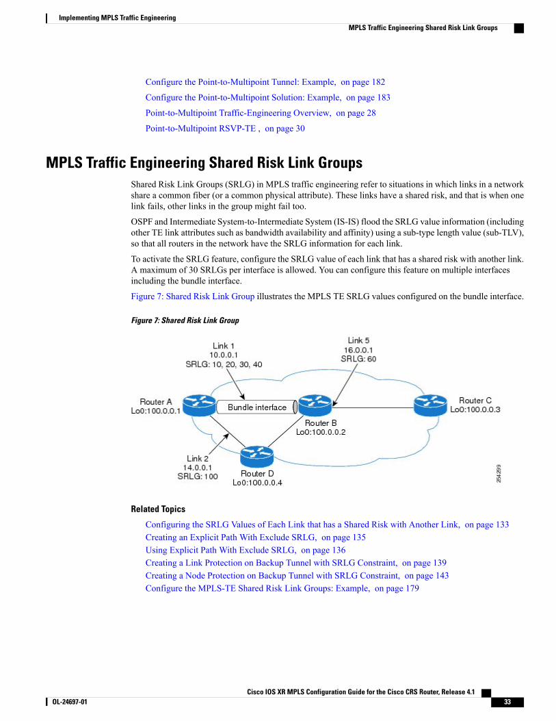
MPLS Traffic Engineering Shared Risk Link GroupsShared Risk Link Groups (SRLG) in MPLS traffic engineering refer to situations in which links in a networkshare a common fiber (or a common physical attribute). These links have a shared risk, and that is when onelink fails, other links in the group might fail too.
OSPF and Intermediate System-to-Intermediate System (IS-IS) flood the SRLG value information (includingother TE link attributes such as bandwidth availability and affinity) using a sub-type length value (sub-TLV),so that all routers in the network have the SRLG information for each link.
To activate the SRLG feature, configure the SRLG value of each link that has a shared risk with another link.A maximum of 30 SRLGs per interface is allowed. You can configure this feature on multiple interfacesincluding the bundle interface.
Figure 7: Shared Risk Link Group illustrates the MPLS TE SRLG values configured on the bundle interface.
Figure 7: Shared Risk Link Group
Related Topics
Configuring the SRLG Values of Each Link that has a Shared Risk with Another Link, on page 133Creating an Explicit Path With Exclude SRLG, on page 135Using Explicit Path With Exclude SRLG, on page 136Creating a Link Protection on Backup Tunnel with SRLG Constraint, on page 139Creating a Node Protection on Backup Tunnel with SRLG Constraint, on page 143Configure the MPLS-TE Shared Risk Link Groups: Example, on page 179
Cisco IOS XR MPLS Configuration Guide for the Cisco CRS Router, Release 4.1 OL-24697-01 33
Implementing MPLS Traffic EngineeringMPLS Traffic Engineering Shared Risk Link Groups
Explicit PathThe Explicit Path configuration allows you to configure the explicit path. An IP explicit path is a list of IPaddresses, each representing a node or link in the explicit path.
The MPLS Traffic Engineering (TE)—IP Explicit Address Exclusion feature provides a means to exclude alink or node from the path for an Multiprotocol Label Switching (MPLS) TE label-switched path (LSP).
This feature is enabled through the explicit-path command that allows you to create an IP explicit path andenter a configuration submode for specifying the path. The feature adds to the submode commands of theexclude-address command for specifying addresses to exclude from the path.
The feature also adds to the submode commands of the exclude-srlg command that allows you to specifythe IP address to get SRLGs to be excluded from the explicit path.
If the excluded address or excluded srlg for an MPLS TE LSP identifies a flooded link, the constraint-basedshortest path first (CSPF) routing algorithm does not consider that link when computing paths for the LSP.If the excluded address specifies a flooded MPLS TE router ID, the CSPF routing algorithm does not allowpaths for the LSP to traverse the node identified by the router ID.
Related Topics
Configuring the SRLG Values of Each Link that has a Shared Risk with Another Link, on page 133Creating an Explicit Path With Exclude SRLG, on page 135Using Explicit Path With Exclude SRLG, on page 136Creating a Link Protection on Backup Tunnel with SRLG Constraint, on page 139Creating a Node Protection on Backup Tunnel with SRLG Constraint, on page 143Configure the MPLS-TE Shared Risk Link Groups: Example, on page 179
Fast ReRoute with SRLG ConstraintsFast ReRoute (FRR) protects MPLS TE Label Switch Paths (LSPs) from link and node failures by locallyrepairing the LSPs at the point of failure. This protection allows data to continue to flow on LSPs, while theirheadend routers attempt to establish new end-to-end LSPs to replace them. FRR locally repairs the protectedLSPs by rerouting them over backup tunnels that bypass failed links or nodes.
Backup tunnels that bypass only a single link of the LSP's path provide Link Protection. They protect LSPsby specifying the protected link IP addresses to extract SRLG values that are to be excluded from the explicitpath, thereby bypassing the failed link. These are referred to as next-hop (NHOP) backup tunnels because
Cisco IOS XR MPLS Configuration Guide for the Cisco CRS Router, Release 4.134 OL-24697-01
Implementing MPLS Traffic EngineeringMPLS Traffic Engineering Shared Risk Link Groups
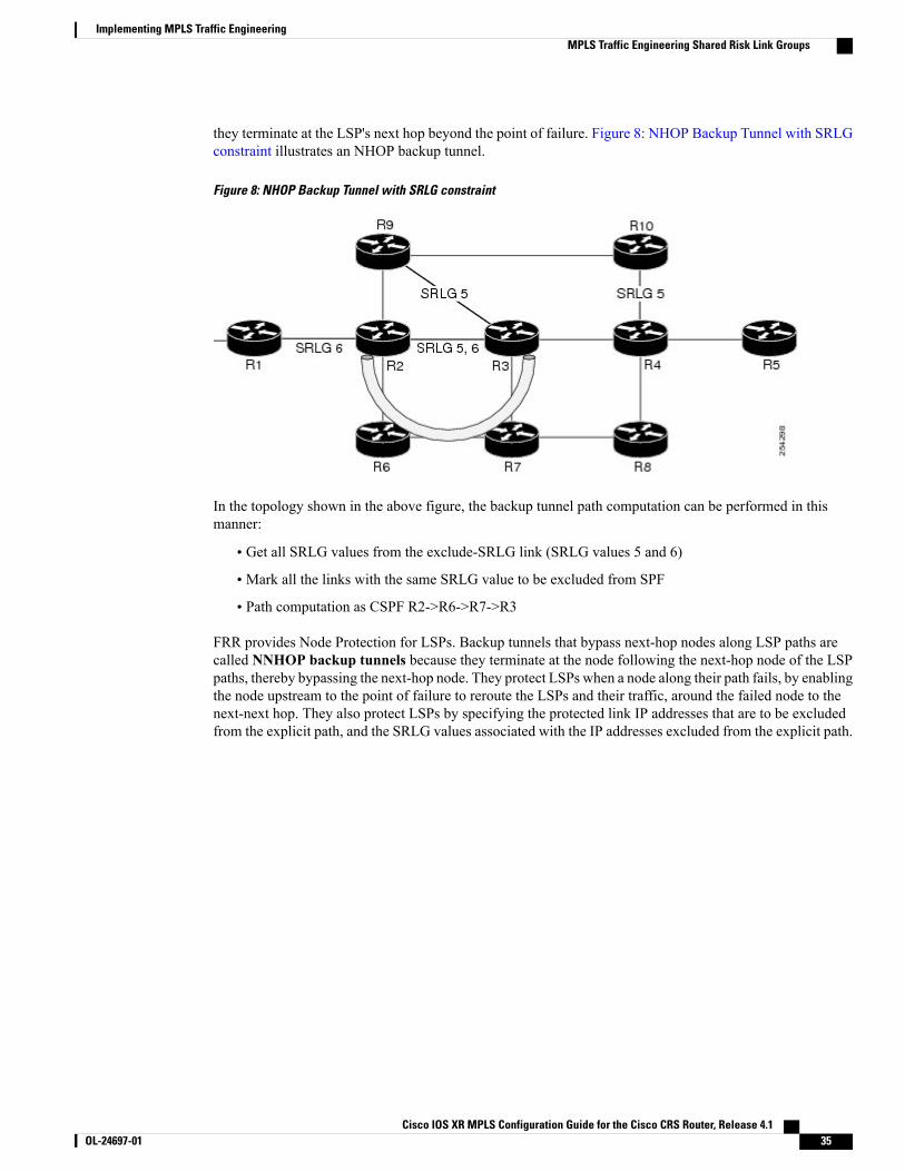
they terminate at the LSP's next hop beyond the point of failure. Figure 8: NHOP Backup Tunnel with SRLGconstraint illustrates an NHOP backup tunnel.
Figure 8: NHOP Backup Tunnel with SRLG constraint
In the topology shown in the above figure, the backup tunnel path computation can be performed in thismanner:
• Get all SRLG values from the exclude-SRLG link (SRLG values 5 and 6)
• Mark all the links with the same SRLG value to be excluded from SPF
• Path computation as CSPF R2->R6->R7->R3
FRR provides Node Protection for LSPs. Backup tunnels that bypass next-hop nodes along LSP paths arecalled NNHOP backup tunnels because they terminate at the node following the next-hop node of the LSPpaths, thereby bypassing the next-hop node. They protect LSPs when a node along their path fails, by enablingthe node upstream to the point of failure to reroute the LSPs and their traffic, around the failed node to thenext-next hop. They also protect LSPs by specifying the protected link IP addresses that are to be excludedfrom the explicit path, and the SRLG values associated with the IP addresses excluded from the explicit path.
Cisco IOS XR MPLS Configuration Guide for the Cisco CRS Router, Release 4.1 OL-24697-01 35
Implementing MPLS Traffic EngineeringMPLS Traffic Engineering Shared Risk Link Groups

NNHOP backup tunnels also provide protection from link failures by bypassing the failed link as well as thenode. Figure 9: NNHOP Backup Tunnel with SRLG constraint illustrates an NNHOP backup tunnel.
Figure 9: NNHOP Backup Tunnel with SRLG constraint
In the topology shown in the above figure, the backup tunnel path computation can be performed in thismanner:
• Get all SRLG values from the exclude-SRLG link (SRLG values 5 and 6)
• Mark all links with the same SRLG value to be excluded from SPF
• Verify path with SRLG constraint
• Path computation as CSPF R2->R9->R10->R4
Related Topics
Configuring the SRLG Values of Each Link that has a Shared Risk with Another Link, on page 133Creating an Explicit Path With Exclude SRLG, on page 135Using Explicit Path With Exclude SRLG, on page 136Creating a Link Protection on Backup Tunnel with SRLG Constraint, on page 139Creating a Node Protection on Backup Tunnel with SRLG Constraint, on page 143Configure the MPLS-TE Shared Risk Link Groups: Example, on page 179
Importance of ProtectionThis section describes the following:
• Delivery of Packets During a Failure
• Multiple Backup Tunnels Protecting the Same Interface
Cisco IOS XR MPLS Configuration Guide for the Cisco CRS Router, Release 4.136 OL-24697-01
Implementing MPLS Traffic EngineeringMPLS Traffic Engineering Shared Risk Link Groups
Related Topics
Configuring the SRLG Values of Each Link that has a Shared Risk with Another Link, on page 133Creating an Explicit Path With Exclude SRLG, on page 135Using Explicit Path With Exclude SRLG, on page 136Creating a Link Protection on Backup Tunnel with SRLG Constraint, on page 139Creating a Node Protection on Backup Tunnel with SRLG Constraint, on page 143Configure the MPLS-TE Shared Risk Link Groups: Example, on page 179
Delivery of Packets During a Failure
Backup tunnels that terminate at the NNHOP protect both the downstream link and node. This providesprotection for link and node failures.
Related Topics
Configuring the SRLG Values of Each Link that has a Shared Risk with Another Link, on page 133Creating an Explicit Path With Exclude SRLG, on page 135Using Explicit Path With Exclude SRLG, on page 136Creating a Link Protection on Backup Tunnel with SRLG Constraint, on page 139Creating a Node Protection on Backup Tunnel with SRLG Constraint, on page 143Configure the MPLS-TE Shared Risk Link Groups: Example, on page 179
Multiple Backup Tunnels Protecting the Same Interface
• Redundancy—If one backup tunnel is down, other backup tunnels protect LSPs.
• Increased backup capacity—If the protected interface is a high-capacity link and no single backup pathexists with an equal capacity, multiple backup tunnels can protect that one high-capacity link. The LSPsusing this link falls over to different backup tunnels, allowing all of the LSPs to have adequate bandwidthprotection during failure (rerouting). If bandwidth protection is not desired, the router spreads LSPsacross all available backup tunnels (that is, there is load balancing across backup tunnels).
Related Topics
Configuring the SRLG Values of Each Link that has a Shared Risk with Another Link, on page 133Creating an Explicit Path With Exclude SRLG, on page 135Using Explicit Path With Exclude SRLG, on page 136Creating a Link Protection on Backup Tunnel with SRLG Constraint, on page 139Creating a Node Protection on Backup Tunnel with SRLG Constraint, on page 143Configure the MPLS-TE Shared Risk Link Groups: Example, on page 179
SRLG LimitationsThere are few limitations to the configured SRLG feature:
• The exclude-address and exclude-srlg options are not allowed in the IP explicit path strict-addressnetwork.
Cisco IOS XR MPLS Configuration Guide for the Cisco CRS Router, Release 4.1 OL-24697-01 37
Implementing MPLS Traffic EngineeringMPLS Traffic Engineering Shared Risk Link Groups
•Whenever SRLG values are modified after tunnels are signalled, they are verified dynamically in thenext path verification cycle.
Related Topics
Configuring the SRLG Values of Each Link that has a Shared Risk with Another Link, on page 133Creating an Explicit Path With Exclude SRLG, on page 135Using Explicit Path With Exclude SRLG, on page 136Creating a Link Protection on Backup Tunnel with SRLG Constraint, on page 139Creating a Node Protection on Backup Tunnel with SRLG Constraint, on page 143Configure the MPLS-TE Shared Risk Link Groups: Example, on page 179
Auto-Tunnel MeshThe MPLS traffic engineering auto-tunnel mesh (Auto-mesh) feature allows you to set up full mesh of TEP2P tunnels automatically with a minimal set of MPLS traffic engineering configurations. You may configureone or more mesh-groups. Each mesh-group requires a destination-list (IPv4 prefix-list) listing destinations,which are used as destinations for creating tunnels for that mesh-group.
You may configure MPLS TE auto-mesh type attribute-sets (templates) and associate them to mesh-groups.LSR creates tunnels using the tunnel properties defined in the attribute-set.
Auto-Tunnel mesh provides benefits:
• Minimizes the initial configuration of the network.
You may configure tunnel properties template and mesh-groups or destination-lists on each TE LSRsthat further creates full mesh of TE tunnels between those LSRs.
• Minimizes future configurations resulting due to network growth.
It eliminates the need to reconfigure each existing TE LSR in order to establish a full mesh of TE tunnelswhenever a new TE LSR is added in the network.
Related Topics
Configuring Auto-Tunnel Mesh Tunnel ID, on page 159
Configuring Auto-tunnel Mesh Unused Timeout, on page 161
Configuring Auto-Tunnel Mesh Group, on page 162
Configuring Tunnel Attribute-Set Templates, on page 164
Enabling LDP on Auto-Tunnel Mesh, on page 167
Destination List (Prefix-List)Auto-mesh tunnels can be automatically created using prefix-list. Each TE enabled router in the networklearns about the TE router IDs through a existing IGP extension.
You can view the router IDs on the router using this command:
show mpls traffic-eng topology | include TE IdIGP Id: 0001.0000.0010.00, MPLS TE Id:100.1.1.1 Router Node (ISIS 1 level-2)
Cisco IOS XR MPLS Configuration Guide for the Cisco CRS Router, Release 4.138 OL-24697-01
Implementing MPLS Traffic EngineeringAuto-Tunnel Mesh
IGP Id: 0001.0000.0011.00, MPLS TE Id:100.2.2.2 Router Node (ISIS 1 level-2)IGP Id: 0001.0000.0012.00, MPLS TE Id:100.3.3.3 Router Node (ISIS 1 level-2)A prefix-list may be configured on each TE router to match a desired set of router IDs (MPLS TE ID as shownin the above output). For example, if a prefix-list is configured to match addresses of 100.0.0.0 with wildcard0.255.255.255, then all 100.x.x.x router IDs are included in the auto-mesh group.
When a new TE router is added in the network and its router ID is also in the block of addresses describedby the prefix-list, for example, 100.x.x.x, then it is added in the auto-mesh group on each existing TE routerwithout having to explicitly modify the prefix-list or perform any additional configuration.
Auto-mesh does not create tunnels to its own (local) TE router IDs.
When prefix-list configurations on all routers are not identical, it can result in non- symmetrical mesh oftunnels between those routers.
Note
Related Topics
Configuring Auto-Tunnel Mesh Tunnel ID, on page 159
Configuring Auto-tunnel Mesh Unused Timeout, on page 161
Configuring Auto-Tunnel Mesh Group, on page 162
Configuring Tunnel Attribute-Set Templates, on page 164
Enabling LDP on Auto-Tunnel Mesh, on page 167
How to Implement Traffic EngineeringTraffic engineering requires coordination among several global neighbor routers, creating traffic engineeringtunnels, setting up forwarding across traffic engineering tunnels, setting up FRR, and creating differentialservice.
These procedures are used to implement MPLS-TE:
Building MPLS-TE TopologyPerform this task to configure MPLS-TE topology (required for traffic engineering tunnel operations).
Before You Begin
Before you start to build the MPLS-TE topology, you must have enabled:
• IGP such as OSPF or IS-IS for MPLS-TE.
• MPLS Label Distribution Protocol (LDP).
• RSVP on the port interface.
• Stable router ID is required at either end of the link to ensure that the link is successful. If you do notassign a router ID, the system defaults to the global router ID. Default router IDs are subject to change,which can result in an unstable link.
• If you are going to use nondefault holdtime or intervals, you must decide the values to which they areset.
Cisco IOS XR MPLS Configuration Guide for the Cisco CRS Router, Release 4.1 OL-24697-01 39
Implementing MPLS Traffic EngineeringHow to Implement Traffic Engineering
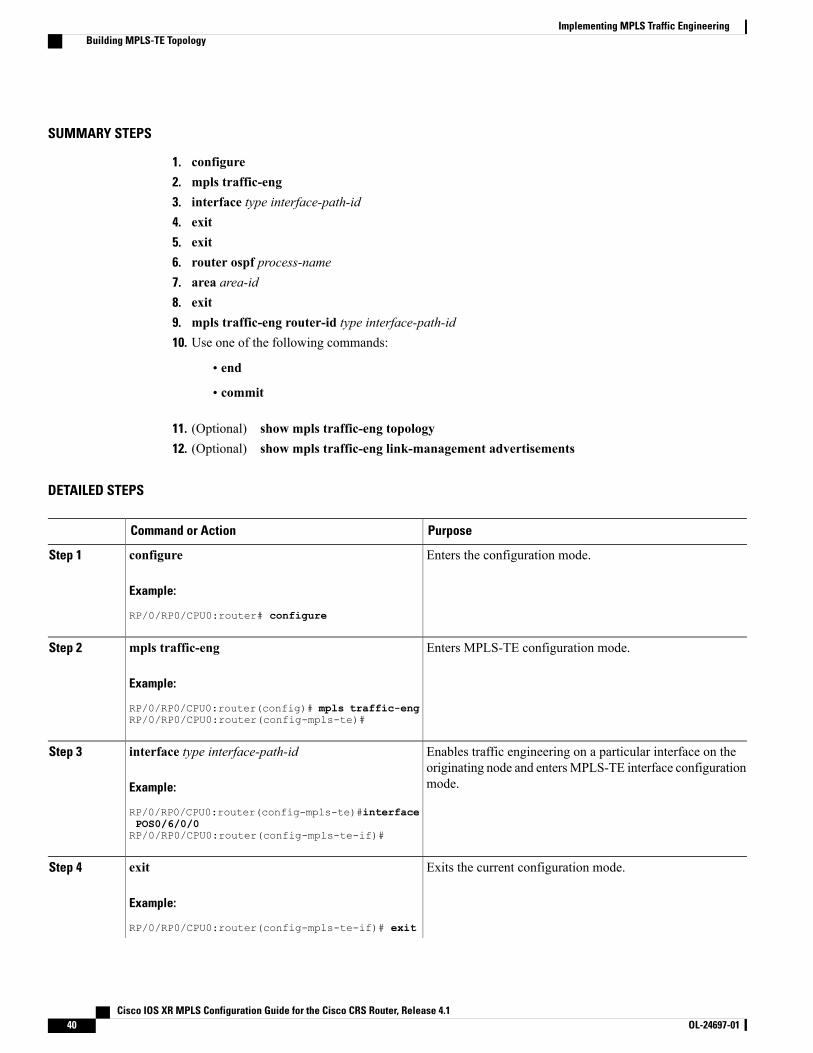
SUMMARY STEPS
1. configure2. mpls traffic-eng3. interface type interface-path-id4. exit5. exit6. router ospf process-name7. area area-id8. exit9. mpls traffic-eng router-id type interface-path-id10. Use one of the following commands:
• end
• commit
11. (Optional) show mpls traffic-eng topology12. (Optional) show mpls traffic-eng link-management advertisements
DETAILED STEPS
PurposeCommand or Action
Enters the configuration mode.configure
Example:
RP/0/RP0/CPU0:router# configure
Step 1
Enters MPLS-TE configuration mode.mpls traffic-eng
Example:
RP/0/RP0/CPU0:router(config)# mpls traffic-eng
Step 2
RP/0/RP0/CPU0:router(config-mpls-te)#
Enables traffic engineering on a particular interface on theoriginating node and entersMPLS-TE interface configurationmode.
interface type interface-path-id
Example:
RP/0/RP0/CPU0:router(config-mpls-te)#interface
Step 3
POS0/6/0/0RP/0/RP0/CPU0:router(config-mpls-te-if)#
Exits the current configuration mode.exit
Example:
RP/0/RP0/CPU0:router(config-mpls-te-if)# exit
Step 4
Cisco IOS XR MPLS Configuration Guide for the Cisco CRS Router, Release 4.140 OL-24697-01
Implementing MPLS Traffic EngineeringBuilding MPLS-TE Topology
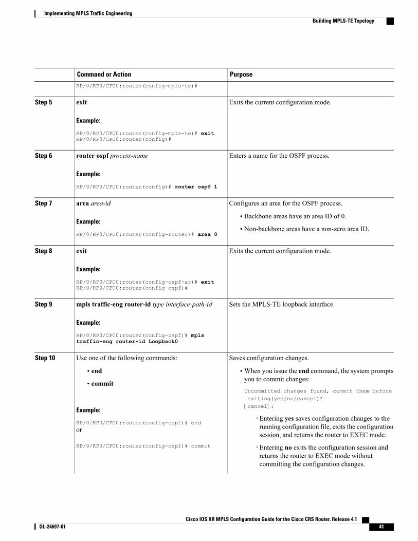
PurposeCommand or Action
RP/0/RP0/CPU0:router(config-mpls-te)#
Exits the current configuration mode.exit
Example:
RP/0/RP0/CPU0:router(config-mpls-te)# exit
Step 5
RP/0/RP0/CPU0:router(config)#
Enters a name for the OSPF process.router ospf process-name
Example:
RP/0/RP0/CPU0:router(config)# router ospf 1
Step 6
Configures an area for the OSPF process.area area-idStep 7
Example:
RP/0/RP0/CPU0:router(config-router)# area 0
• Backbone areas have an area ID of 0.
• Non-backbone areas have a non-zero area ID.
Exits the current configuration mode.exit
Example:
RP/0/RP0/CPU0:router(config-ospf-ar)# exit
Step 8
RP/0/RP0/CPU0:router(config-ospf)#
Sets the MPLS-TE loopback interface.mpls traffic-eng router-id type interface-path-id
Example:
RP/0/RP0/CPU0:router(config-ospf)# mpls
Step 9
traffic-eng router-id Loopback0
Saves configuration changes.Use one of the following commands:Step 10
• end •When you issue the end command, the system promptsyou to commit changes:
Uncommitted changes found, commit them beforeexiting(yes/no/cancel)?[cancel]:
• commit
Example:
RP/0/RP0/CPU0:router(config-ospf)# end◦Entering yes saves configuration changes to therunning configuration file, exits the configurationsession, and returns the router to EXEC mode.
or
RP/0/RP0/CPU0:router(config-ospf)# commit ◦Entering no exits the configuration session andreturns the router to EXEC mode withoutcommitting the configuration changes.
Cisco IOS XR MPLS Configuration Guide for the Cisco CRS Router, Release 4.1 OL-24697-01 41
Implementing MPLS Traffic EngineeringBuilding MPLS-TE Topology
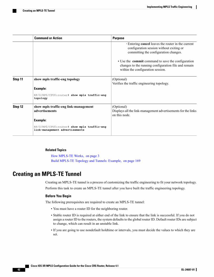
PurposeCommand or Action
◦Entering cancel leaves the router in the currentconfiguration session without exiting orcommitting the configuration changes.
• Use the commit command to save the configurationchanges to the running configuration file and remainwithin the configuration session.
(Optional)Verifies the traffic engineering topology.
show mpls traffic-eng topology
Example:
RP/0/RP0/CPU0:router# show mpls traffic-eng
Step 11
topology
(Optional)Displays all the link-management advertisements for the linkson this node.
show mpls traffic-eng link-managementadvertisements
Example:
RP/0/RP0/CPU0:router# show mpls traffic-eng
Step 12
link-management advertisements
Related Topics
How MPLS-TE Works, on page 3Build MPLS-TE Topology and Tunnels: Example, on page 169
Creating an MPLS-TE TunnelCreating an MPLS-TE tunnel is a process of customizing the traffic engineering to fit your network topology.
Perform this task to create an MPLS-TE tunnel after you have built the traffic engineering topology.
Before You Begin
The following prerequisites are required to create an MPLS-TE tunnel:
• You must have a router ID for the neighboring router.
• Stable router ID is required at either end of the link to ensure that the link is successful. If you do notassign a router ID to the routers, the system defaults to the global router ID. Default router IDs are subjectto change, which can result in an unstable link.
• If you are going to use nondefault holdtime or intervals, you must decide the values to which they areset.
Cisco IOS XR MPLS Configuration Guide for the Cisco CRS Router, Release 4.142 OL-24697-01
Implementing MPLS Traffic EngineeringCreating an MPLS-TE Tunnel
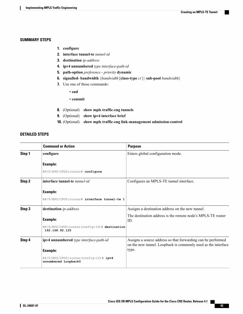
SUMMARY STEPS
1. configure2. interface tunnel-te tunnel-id3. destination ip-address4. ipv4 unnumbered type interface-path-id5. path-option preference - priority dynamic6. signalled- bandwidth {bandwidth [class-type ct ] | sub-pool bandwidth}7. Use one of these commands:
• end
• commit
8. (Optional) show mpls traffic-eng tunnels9. (Optional) show ipv4 interface brief10. (Optional) show mpls traffic-eng link-management admission-control
DETAILED STEPS
PurposeCommand or Action
Enters global configuration mode.configure
Example:
RP/0/RP0/CPU0:router# configure
Step 1
Configures an MPLS-TE tunnel interface.interface tunnel-te tunnel-id
Example:
RP/0/RP0/CPU0:router# interface tunnel-te 1
Step 2
Assigns a destination address on the new tunnel.destination ip-addressStep 3
Example:
RP/0/RP0/CPU0:router(config-if)# destination
The destination address is the remote node’s MPLS-TE routerID.
192.168.92.125
Assigns a source address so that forwarding can be performedon the new tunnel. Loopback is commonly used as the interfacetype.
ipv4 unnumbered type interface-path-id
Example:
RP/0/RP0/CPU0:router(config-if)# ipv4
Step 4
unnumbered Loopback0
Cisco IOS XR MPLS Configuration Guide for the Cisco CRS Router, Release 4.1 OL-24697-01 43
Implementing MPLS Traffic EngineeringCreating an MPLS-TE Tunnel
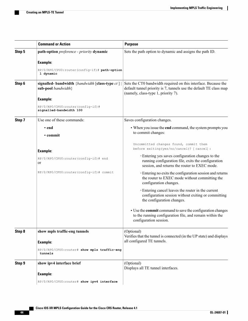
PurposeCommand or Action
Sets the path option to dynamic and assigns the path ID.path-option preference - priority dynamic
Example:
RP/0/RP0/CPU0:router(config-if)# path-option
Step 5
l dynamic
Sets the CT0 bandwidth required on this interface. Because thedefault tunnel priority is 7, tunnels use the default TE class map(namely, class-type 1, priority 7).
signalled- bandwidth {bandwidth [class-type ct ] |sub-pool bandwidth}
Example:
RP/0/RP0/CPU0:router(config-if)#
Step 6
signalled-bandwidth 100
Saves configuration changes.Use one of these commands:Step 7
• end •When you issue the end command, the system prompts youto commit changes:
Uncommitted changes found, commit thembefore exiting(yes/no/cancel)? [cancel]:
• commit
Example:
RP/0/RP0/CPU0:router(config-if)# end◦Entering yes saves configuration changes to therunning configuration file, exits the configurationsession, and returns the router to EXEC mode.
or
RP/0/RP0/CPU0:router(config-if)# commit ◦Entering no exits the configuration session and returnsthe router to EXEC mode without committing theconfiguration changes.
◦Entering cancel leaves the router in the currentconfiguration session without exiting or committingthe configuration changes.
• Use the commit command to save the configuration changesto the running configuration file, and remain within theconfiguration session.
(Optional)Verifies that the tunnel is connected (in the UP state) and displaysall configured TE tunnels.
show mpls traffic-eng tunnels
Example:
RP/0/RP0/CPU0:router# show mpls traffic-eng
Step 8
tunnels
(Optional)Displays all TE tunnel interfaces.
show ipv4 interface brief
Example:
RP/0/RP0/CPU0:router# show ipv4 interface
Step 9
Cisco IOS XR MPLS Configuration Guide for the Cisco CRS Router, Release 4.144 OL-24697-01
Implementing MPLS Traffic EngineeringCreating an MPLS-TE Tunnel
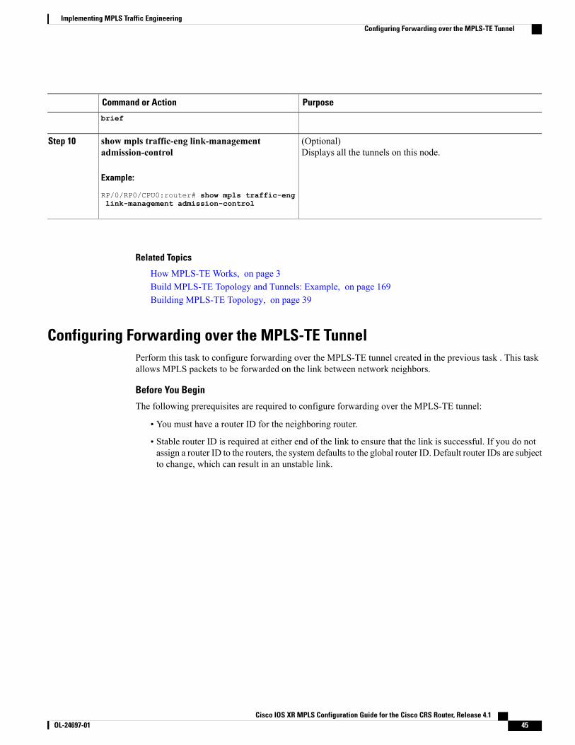
PurposeCommand or Action
brief
(Optional)Displays all the tunnels on this node.
show mpls traffic-eng link-managementadmission-control
Example:
RP/0/RP0/CPU0:router# show mpls traffic-eng
Step 10
link-management admission-control
Related Topics
How MPLS-TE Works, on page 3Build MPLS-TE Topology and Tunnels: Example, on page 169Building MPLS-TE Topology, on page 39
Configuring Forwarding over the MPLS-TE TunnelPerform this task to configure forwarding over the MPLS-TE tunnel created in the previous task . This taskallows MPLS packets to be forwarded on the link between network neighbors.
Before You Begin
The following prerequisites are required to configure forwarding over the MPLS-TE tunnel:
• You must have a router ID for the neighboring router.
• Stable router ID is required at either end of the link to ensure that the link is successful. If you do notassign a router ID to the routers, the system defaults to the global router ID. Default router IDs are subjectto change, which can result in an unstable link.
Cisco IOS XR MPLS Configuration Guide for the Cisco CRS Router, Release 4.1 OL-24697-01 45
Implementing MPLS Traffic EngineeringConfiguring Forwarding over the MPLS-TE Tunnel
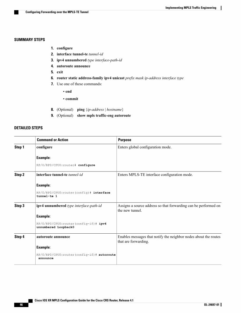
SUMMARY STEPS
1. configure2. interface tunnel-te tunnel-id3. ipv4 unnumbered type interface-path-id4. autoroute announce5. exit6. router static address-family ipv4 unicast prefix mask ip-address interface type7. Use one of these commands:
• end
• commit
8. (Optional) ping {ip-address | hostname}9. (Optional) show mpls traffic-eng autoroute
DETAILED STEPS
PurposeCommand or Action
Enters global configuration mode.configure
Example:
RP/0/RP0/CPU0:router# configure
Step 1
Enters MPLS-TE interface configuration mode.interface tunnel-te tunnel-id
Example:
RP/0/RP0/CPU0:router(config)# interface
Step 2
tunnel-te 1
Assigns a source address so that forwarding can be performed onthe new tunnel.
ipv4 unnumbered type interface-path-id
Example:
RP/0/RP0/CPU0:router(config-if)# ipv4
Step 3
unnumbered Loopback0
Enables messages that notify the neighbor nodes about the routesthat are forwarding.
autoroute announce
Example:
RP/0/RP0/CPU0:router(config-if)# autoroute
Step 4
announce
Cisco IOS XR MPLS Configuration Guide for the Cisco CRS Router, Release 4.146 OL-24697-01
Implementing MPLS Traffic EngineeringConfiguring Forwarding over the MPLS-TE Tunnel
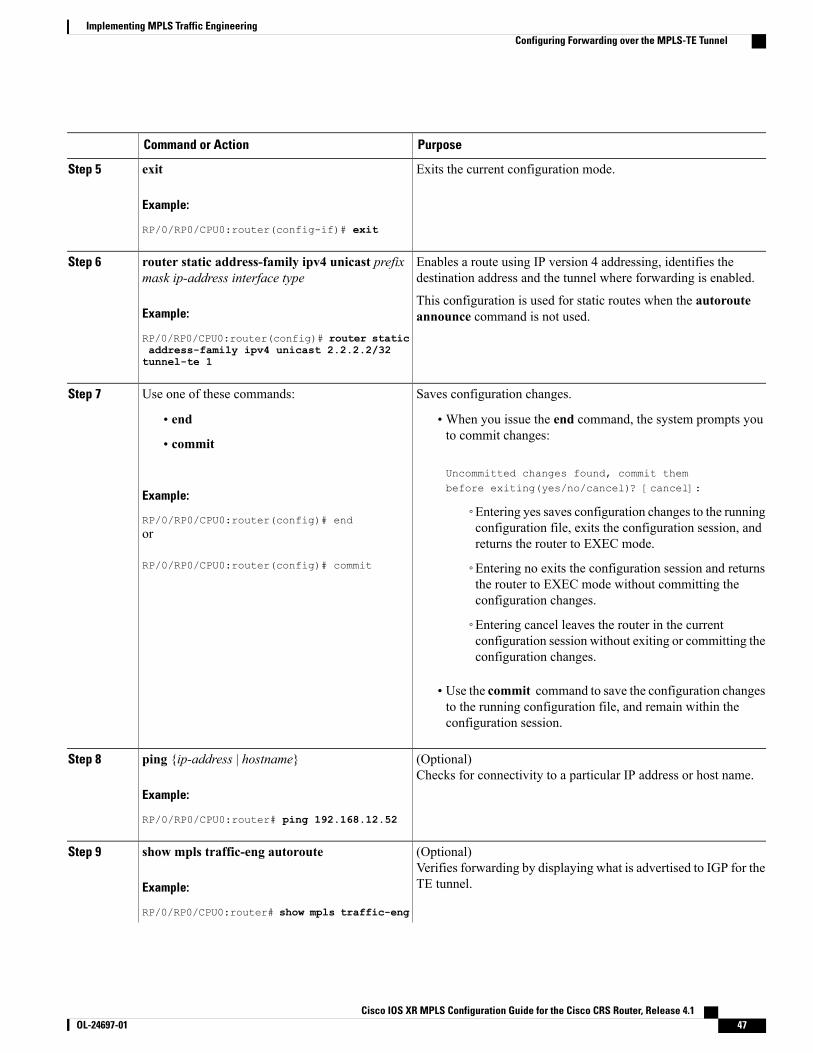
PurposeCommand or Action
Exits the current configuration mode.exit
Example:
RP/0/RP0/CPU0:router(config-if)# exit
Step 5
Enables a route using IP version 4 addressing, identifies thedestination address and the tunnel where forwarding is enabled.
router static address-family ipv4 unicast prefixmask ip-address interface type
Step 6
Example:
RP/0/RP0/CPU0:router(config)# router static
This configuration is used for static routes when the autorouteannounce command is not used.
address-family ipv4 unicast 2.2.2.2/32tunnel-te 1
Saves configuration changes.Use one of these commands:Step 7
• end •When you issue the end command, the system prompts youto commit changes:
Uncommitted changes found, commit thembefore exiting(yes/no/cancel)? [cancel]:
• commit
Example:
RP/0/RP0/CPU0:router(config)# end◦Entering yes saves configuration changes to the runningconfiguration file, exits the configuration session, andreturns the router to EXEC mode.
or
RP/0/RP0/CPU0:router(config)# commit ◦Entering no exits the configuration session and returnsthe router to EXEC mode without committing theconfiguration changes.
◦Entering cancel leaves the router in the currentconfiguration session without exiting or committing theconfiguration changes.
• Use the commit command to save the configuration changesto the running configuration file, and remain within theconfiguration session.
(Optional)Checks for connectivity to a particular IP address or host name.
ping {ip-address | hostname}
Example:
RP/0/RP0/CPU0:router# ping 192.168.12.52
Step 8
(Optional)Verifies forwarding by displaying what is advertised to IGP for theTE tunnel.
show mpls traffic-eng autoroute
Example:
RP/0/RP0/CPU0:router# show mpls traffic-eng
Step 9
Cisco IOS XR MPLS Configuration Guide for the Cisco CRS Router, Release 4.1 OL-24697-01 47
Implementing MPLS Traffic EngineeringConfiguring Forwarding over the MPLS-TE Tunnel
PurposeCommand or Action
autoroute
Related Topics
Overview of MPLS Traffic Engineering, on page 3Creating an MPLS-TE Tunnel, on page 42
Protecting MPLS Tunnels with Fast ReroutePerform this task to protect MPLS-TE tunnels, as created in the previous task.
Although this task is similar to the previous task, its importance makes it necessary to present as part ofthe tasks required for traffic engineering on Cisco IOS XR software.
Note
Before You Begin
The following prerequisites are required to protect MPLS-TE tunnels:
• You must have a router ID for the neighboring router.
• Stable router ID is required at either end of the link to ensure that the link is successful. If you do notassign a router ID to the routers, the system defaults to the global router ID. Default router IDs are subjectto change, which can result in an unstable link.
• You must first configure a primary tunnel.
Cisco IOS XR MPLS Configuration Guide for the Cisco CRS Router, Release 4.148 OL-24697-01
Implementing MPLS Traffic EngineeringProtecting MPLS Tunnels with Fast Reroute
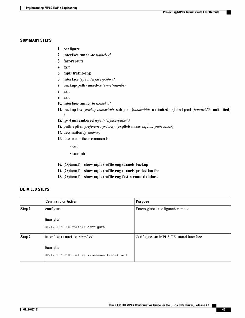
SUMMARY STEPS
1. configure2. interface tunnel-te tunnel-id3. fast-reroute4. exit5. mpls traffic-eng6. interface type interface-path-id7. backup-path tunnel-te tunnel-number8. exit9. exit10. interface tunnel-te tunnel-id11. backup-bw {backup bandwidth | sub-pool {bandwidth | unlimited} | global-pool {bandwidth | unlimited}
}12. ipv4 unnumbered type interface-path-id13. path-option preference-priority {explicit name explicit-path-name}14. destination ip-address15. Use one of these commands:
• end
• commit
16. (Optional) show mpls traffic-eng tunnels backup17. (Optional) show mpls traffic-eng tunnels protection frr18. (Optional) show mpls traffic-eng fast-reroute database
DETAILED STEPS
PurposeCommand or Action
Enters global configuration mode.configure
Example:
RP/0/RP0/CPU0:router# configure
Step 1
Configures an MPLS-TE tunnel interface.interface tunnel-te tunnel-id
Example:
RP/0/RP0/CPU0:router# interface tunnel-te 1
Step 2
Cisco IOS XR MPLS Configuration Guide for the Cisco CRS Router, Release 4.1 OL-24697-01 49
Implementing MPLS Traffic EngineeringProtecting MPLS Tunnels with Fast Reroute
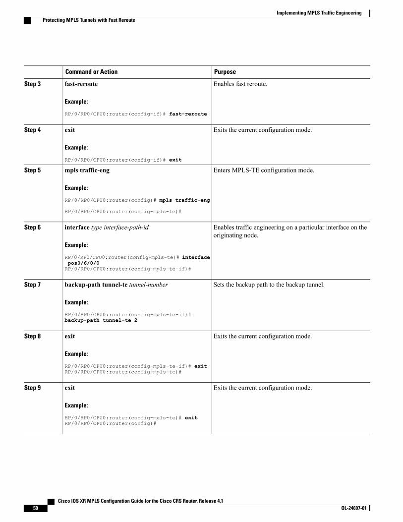
PurposeCommand or Action
Enables fast reroute.fast-reroute
Example:
RP/0/RP0/CPU0:router(config-if)# fast-reroute
Step 3
Exits the current configuration mode.exit
Example:
RP/0/RP0/CPU0:router(config-if)# exit
Step 4
Enters MPLS-TE configuration mode.mpls traffic-eng
Example:
RP/0/RP0/CPU0:router(config)# mpls traffic-eng
Step 5
RP/0/RP0/CPU0:router(config-mpls-te)#
Enables traffic engineering on a particular interface on theoriginating node.
interface type interface-path-id
Example:
RP/0/RP0/CPU0:router(config-mpls-te)# interface
Step 6
pos0/6/0/0RP/0/RP0/CPU0:router(config-mpls-te-if)#
Sets the backup path to the backup tunnel.backup-path tunnel-te tunnel-number
Example:
RP/0/RP0/CPU0:router(config-mpls-te-if)#
Step 7
backup-path tunnel-te 2
Exits the current configuration mode.exit
Example:
RP/0/RP0/CPU0:router(config-mpls-te-if)# exit
Step 8
RP/0/RP0/CPU0:router(config-mpls-te)#
Exits the current configuration mode.exit
Example:
RP/0/RP0/CPU0:router(config-mpls-te)# exit
Step 9
RP/0/RP0/CPU0:router(config)#
Cisco IOS XR MPLS Configuration Guide for the Cisco CRS Router, Release 4.150 OL-24697-01
Implementing MPLS Traffic EngineeringProtecting MPLS Tunnels with Fast Reroute
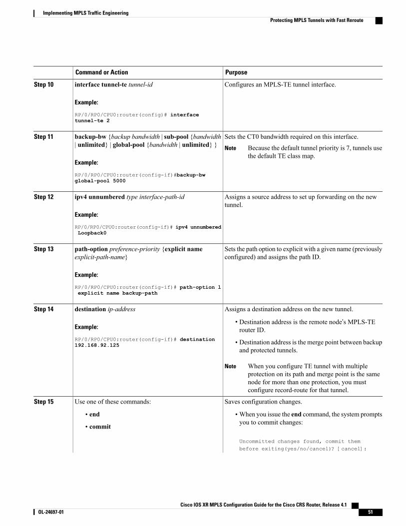
PurposeCommand or Action
Configures an MPLS-TE tunnel interface.interface tunnel-te tunnel-id
Example:
RP/0/RP0/CPU0:router(config)# interface
Step 10
tunnel-te 2
Sets the CT0 bandwidth required on this interface.backup-bw {backup bandwidth | sub-pool {bandwidth| unlimited} | global-pool {bandwidth | unlimited} }
Step 11
Because the default tunnel priority is 7, tunnels usethe default TE class map.
Note
Example:
RP/0/RP0/CPU0:router(config-if)#backup-bwglobal-pool 5000
Assigns a source address to set up forwarding on the newtunnel.
ipv4 unnumbered type interface-path-id
Example:
RP/0/RP0/CPU0:router(config-if)# ipv4 unnumbered
Step 12
Loopback0
Sets the path option to explicit with a given name (previouslyconfigured) and assigns the path ID.
path-option preference-priority {explicit nameexplicit-path-name}
Example:
RP/0/RP0/CPU0:router(config-if)# path-option l
Step 13
explicit name backup-path
Assigns a destination address on the new tunnel.destination ip-addressStep 14
Example:
RP/0/RP0/CPU0:router(config-if)# destination
• Destination address is the remote node’s MPLS-TErouter ID.
• Destination address is the merge point between backupand protected tunnels.
192.168.92.125
When you configure TE tunnel with multipleprotection on its path and merge point is the samenode for more than one protection, you mustconfigure record-route for that tunnel.
Note
Saves configuration changes.Use one of these commands:Step 15
• end •When you issue the end command, the system promptsyou to commit changes:
Uncommitted changes found, commit thembefore exiting(yes/no/cancel)? [cancel]:
• commit
Cisco IOS XR MPLS Configuration Guide for the Cisco CRS Router, Release 4.1 OL-24697-01 51
Implementing MPLS Traffic EngineeringProtecting MPLS Tunnels with Fast Reroute
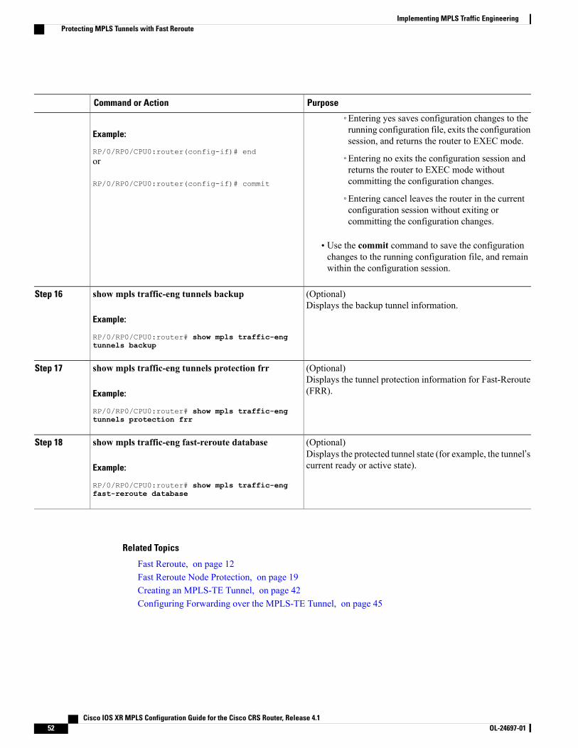
PurposeCommand or Action
Example:
RP/0/RP0/CPU0:router(config-if)# end
◦Entering yes saves configuration changes to therunning configuration file, exits the configurationsession, and returns the router to EXEC mode.
◦Entering no exits the configuration session andreturns the router to EXEC mode withoutcommitting the configuration changes.
or
RP/0/RP0/CPU0:router(config-if)# commit
◦Entering cancel leaves the router in the currentconfiguration session without exiting orcommitting the configuration changes.
• Use the commit command to save the configurationchanges to the running configuration file, and remainwithin the configuration session.
(Optional)Displays the backup tunnel information.
show mpls traffic-eng tunnels backup
Example:
RP/0/RP0/CPU0:router# show mpls traffic-eng
Step 16
tunnels backup
(Optional)Displays the tunnel protection information for Fast-Reroute(FRR).
show mpls traffic-eng tunnels protection frr
Example:
RP/0/RP0/CPU0:router# show mpls traffic-eng
Step 17
tunnels protection frr
(Optional)Displays the protected tunnel state (for example, the tunnel’scurrent ready or active state).
show mpls traffic-eng fast-reroute database
Example:
RP/0/RP0/CPU0:router# show mpls traffic-eng
Step 18
fast-reroute database
Related Topics
Fast Reroute, on page 12Fast Reroute Node Protection, on page 19Creating an MPLS-TE Tunnel, on page 42Configuring Forwarding over the MPLS-TE Tunnel, on page 45
Cisco IOS XR MPLS Configuration Guide for the Cisco CRS Router, Release 4.152 OL-24697-01
Implementing MPLS Traffic EngineeringProtecting MPLS Tunnels with Fast Reroute
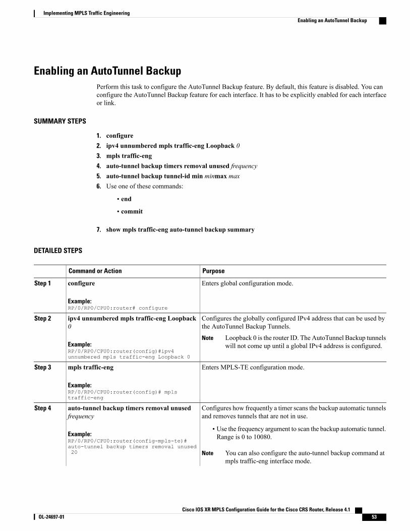
Enabling an AutoTunnel BackupPerform this task to configure the AutoTunnel Backup feature. By default, this feature is disabled. You canconfigure the AutoTunnel Backup feature for each interface. It has to be explicitly enabled for each interfaceor link.
SUMMARY STEPS
1. configure2. ipv4 unnumbered mpls traffic-eng Loopback 03. mpls traffic-eng4. auto-tunnel backup timers removal unused frequency5. auto-tunnel backup tunnel-id min minmax max6. Use one of these commands:
• end
• commit
7. show mpls traffic-eng auto-tunnel backup summary
DETAILED STEPS
PurposeCommand or Action
Enters global configuration mode.configure
Example:RP/0/RP0/CPU0:router# configure
Step 1
Configures the globally configured IPv4 address that can be used bythe AutoTunnel Backup Tunnels.
ipv4 unnumbered mpls traffic-eng Loopback0
Step 2
Example:RP/0/RP0/CPU0:router(config)#ipv4unnumbered mpls traffic-eng Loopback 0
Loopback 0 is the router ID. The AutoTunnel Backup tunnelswill not come up until a global IPv4 address is configured.
Note
Enters MPLS-TE configuration mode.mpls traffic-eng
Example:RP/0/RP0/CPU0:router(config)# mplstraffic-eng
Step 3
Configures how frequently a timer scans the backup automatic tunnelsand removes tunnels that are not in use.
auto-tunnel backup timers removal unusedfrequency
Step 4
Example:RP/0/RP0/CPU0:router(config-mpls-te)#auto-tunnel backup timers removal unused20
• Use the frequency argument to scan the backup automatic tunnel.Range is 0 to 10080.
You can also configure the auto-tunnel backup command atmpls traffic-eng interface mode.
Note
Cisco IOS XR MPLS Configuration Guide for the Cisco CRS Router, Release 4.1 OL-24697-01 53
Implementing MPLS Traffic EngineeringEnabling an AutoTunnel Backup
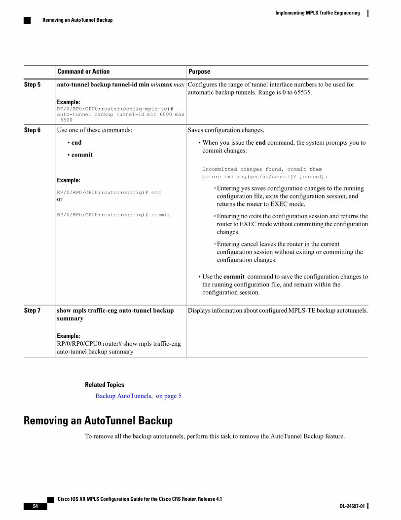
PurposeCommand or Action
Configures the range of tunnel interface numbers to be used forautomatic backup tunnels. Range is 0 to 65535.
auto-tunnel backup tunnel-idminminmaxmax
Example:RP/0/RP0/CPU0:router(config-mpls-te)#auto-tunnel backup tunnel-id min 6000 max6500
Step 5
Saves configuration changes.Use one of these commands:Step 6
• end •When you issue the end command, the system prompts you tocommit changes:
Uncommitted changes found, commit thembefore exiting(yes/no/cancel)? [cancel]:
• commit
Example:
RP/0/RP0/CPU0:router(config)# end◦Entering yes saves configuration changes to the runningconfiguration file, exits the configuration session, andreturns the router to EXEC mode.
or
RP/0/RP0/CPU0:router(config)# commit ◦Entering no exits the configuration session and returns therouter to EXECmodewithout committing the configurationchanges.
◦Entering cancel leaves the router in the currentconfiguration session without exiting or committing theconfiguration changes.
• Use the commit command to save the configuration changes tothe running configuration file, and remain within theconfiguration session.
Displays information about configuredMPLS-TE backup autotunnels.show mpls traffic-eng auto-tunnel backupsummary
Step 7
Example:RP/0/RP0/CPU0:router# show mpls traffic-engauto-tunnel backup summary
Related Topics
Backup AutoTunnels, on page 5
Removing an AutoTunnel BackupTo remove all the backup autotunnels, perform this task to remove the AutoTunnel Backup feature.
Cisco IOS XR MPLS Configuration Guide for the Cisco CRS Router, Release 4.154 OL-24697-01
Implementing MPLS Traffic EngineeringRemoving an AutoTunnel Backup
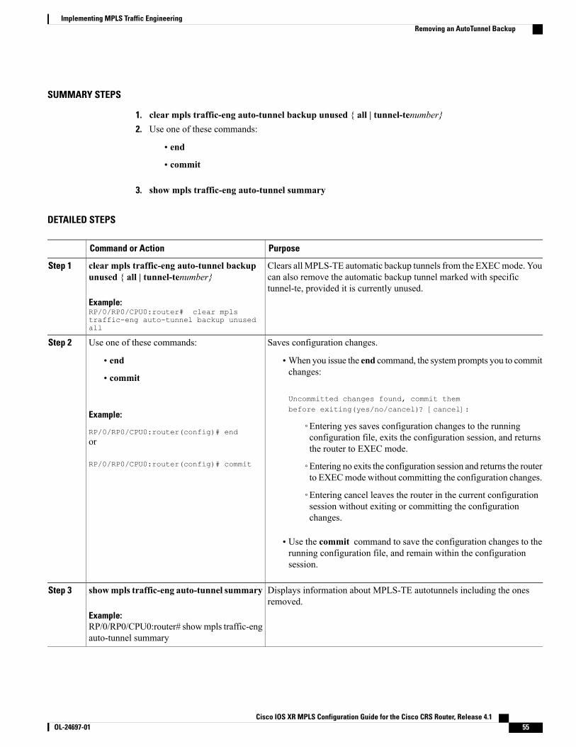
SUMMARY STEPS
1. clear mpls traffic-eng auto-tunnel backup unused { all | tunnel-tenumber}2. Use one of these commands:
• end
• commit
3. show mpls traffic-eng auto-tunnel summary
DETAILED STEPS
PurposeCommand or Action
Clears all MPLS-TE automatic backup tunnels from the EXECmode. Youcan also remove the automatic backup tunnel marked with specifictunnel-te, provided it is currently unused.
clear mpls traffic-eng auto-tunnel backupunused { all | tunnel-tenumber}
Example:RP/0/RP0/CPU0:router# clear mplstraffic-eng auto-tunnel backup unusedall
Step 1
Saves configuration changes.Use one of these commands:Step 2
• end •When you issue the end command, the system prompts you to commitchanges:
Uncommitted changes found, commit thembefore exiting(yes/no/cancel)? [cancel]:
• commit
Example:
RP/0/RP0/CPU0:router(config)# end◦Entering yes saves configuration changes to the runningconfiguration file, exits the configuration session, and returnsthe router to EXEC mode.
or
RP/0/RP0/CPU0:router(config)# commit ◦Entering no exits the configuration session and returns the routerto EXECmode without committing the configuration changes.
◦Entering cancel leaves the router in the current configurationsession without exiting or committing the configurationchanges.
• Use the commit command to save the configuration changes to therunning configuration file, and remain within the configurationsession.
Displays information about MPLS-TE autotunnels including the onesremoved.
showmpls traffic-eng auto-tunnel summary
Example:
Step 3
RP/0/RP0/CPU0:router# showmpls traffic-engauto-tunnel summary
Cisco IOS XR MPLS Configuration Guide for the Cisco CRS Router, Release 4.1 OL-24697-01 55
Implementing MPLS Traffic EngineeringRemoving an AutoTunnel Backup
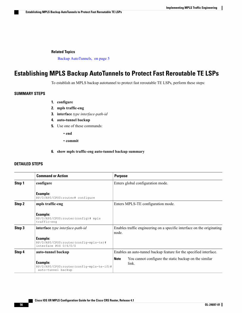
Related Topics
Backup AutoTunnels, on page 5
Establishing MPLS Backup AutoTunnels to Protect Fast Reroutable TE LSPsTo establish an MPLS backup autotunnel to protect fast reroutable TE LSPs, perform these steps:
SUMMARY STEPS
1. configure2. mpls traffic-eng3. interface type interface-path-id4. auto-tunnel backup5. Use one of these commands:
• end
• commit
6. show mpls traffic-eng auto-tunnel backup summary
DETAILED STEPS
PurposeCommand or Action
Enters global configuration mode.configure
Example:RP/0/RP0/CPU0:router# configure
Step 1
Enters MPLS-TE configuration mode.mpls traffic-eng
Example:RP/0/RP0/CPU0:router(config)# mplstraffic-eng
Step 2
Enables traffic engineering on a specific interface on the originatingnode.
interface type interface-path-id
Example:RP/0/RP0/CPU0:router(config-mpls-te)#interface POS 0/6/0/0
Step 3
Enables an auto-tunnel backup feature for the specified interface.auto-tunnel backupStep 4
Example:RP/0/RP0/CPU0:router(config-mpls-te-if)#auto-tunnel backup
You cannot configure the static backup on the similarlink.
Note
Cisco IOS XR MPLS Configuration Guide for the Cisco CRS Router, Release 4.156 OL-24697-01
Implementing MPLS Traffic EngineeringEstablishing MPLS Backup AutoTunnels to Protect Fast Reroutable TE LSPs
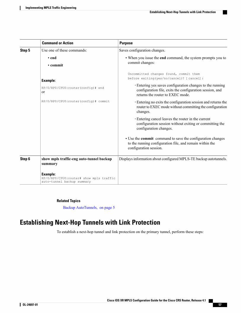
PurposeCommand or Action
Saves configuration changes.Use one of these commands:Step 5
• end •When you issue the end command, the system prompts you tocommit changes:
Uncommitted changes found, commit thembefore exiting(yes/no/cancel)? [cancel]:
• commit
Example:
RP/0/RP0/CPU0:router(config)# end◦Entering yes saves configuration changes to the runningconfiguration file, exits the configuration session, andreturns the router to EXEC mode.
or
RP/0/RP0/CPU0:router(config)# commit ◦Entering no exits the configuration session and returns therouter to EXECmodewithout committing the configurationchanges.
◦Entering cancel leaves the router in the currentconfiguration session without exiting or committing theconfiguration changes.
• Use the commit command to save the configuration changesto the running configuration file, and remain within theconfiguration session.
Displays information about configuredMPLS-TE backup autotunnels.show mpls traffic-eng auto-tunnel backupsummary
Step 6
Example:RP/0/RP0/CPU0:router# show mpls trafficauto-tunnel backup summary
Related Topics
Backup AutoTunnels, on page 5
Establishing Next-Hop Tunnels with Link ProtectionTo establish a next-hop tunnel and link protection on the primary tunnel, perform these steps:
Cisco IOS XR MPLS Configuration Guide for the Cisco CRS Router, Release 4.1 OL-24697-01 57
Implementing MPLS Traffic EngineeringEstablishing Next-Hop Tunnels with Link Protection
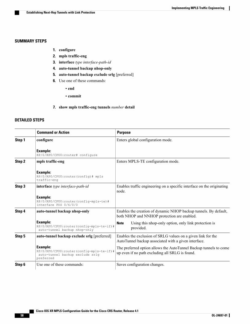
SUMMARY STEPS
1. configure2. mpls traffic-eng3. interface type interface-path-id4. auto-tunnel backup nhop-only5. auto-tunnel backup exclude srlg [preferred]6. Use one of these commands:
• end
• commit
7. show mpls traffic-eng tunnels number detail
DETAILED STEPS
PurposeCommand or Action
Enters global configuration mode.configure
Example:RP/0/RP0/CPU0:router# configure
Step 1
Enters MPLS-TE configuration mode.mpls traffic-eng
Example:RP/0/RP0/CPU0:router(config)# mplstraffic-eng
Step 2
Enables traffic engineering on a specific interface on the originatingnode.
interface type interface-path-id
Example:RP/0/RP0/CPU0:router(config-mpls-te)#interface POS 0/6/0/0
Step 3
Enables the creation of dynamic NHOP backup tunnels. By default,both NHOP and NNHOP protection are enabled.
auto-tunnel backup nhop-only
Example:RP/0/RP0/CPU0:router(config-mpls-te-if)#auto-tunnel backup nhop-only
Step 4
Using this nhop-only option, only link protection isprovided.
Note
Enables the exclusion of SRLG values on a given link for theAutoTunnel backup associated with a given interface.
auto-tunnel backup exclude srlg [preferred]
Example:RP/0/RP0/CPU0:router(config-mpls-te-if)#auto-tunnel backup exclude srlgpreferred
Step 5
The preferred option allows the AutoTunnel Backup tunnels to comeup even if no path excluding all SRLG is found.
Saves configuration changes.Use one of these commands:Step 6
Cisco IOS XR MPLS Configuration Guide for the Cisco CRS Router, Release 4.158 OL-24697-01
Implementing MPLS Traffic EngineeringEstablishing Next-Hop Tunnels with Link Protection
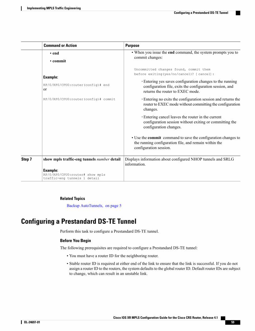
PurposeCommand or Action
•When you issue the end command, the system prompts you tocommit changes:
Uncommitted changes found, commit thembefore exiting(yes/no/cancel)? [cancel]:
• end
• commit
Example:
RP/0/RP0/CPU0:router(config)# end◦Entering yes saves configuration changes to the runningconfiguration file, exits the configuration session, andreturns the router to EXEC mode.or
RP/0/RP0/CPU0:router(config)# commit ◦Entering no exits the configuration session and returns therouter to EXECmodewithout committing the configurationchanges.
◦Entering cancel leaves the router in the currentconfiguration session without exiting or committing theconfiguration changes.
• Use the commit command to save the configuration changes tothe running configuration file, and remain within theconfiguration session.
Displays information about configured NHOP tunnels and SRLGinformation.
show mpls traffic-eng tunnels number detail
Example:RP/0/RP0/CPU0:router# show mplstraffic-eng tunnels 1 detail
Step 7
Related Topics
Backup AutoTunnels, on page 5
Configuring a Prestandard DS-TE TunnelPerform this task to configure a Prestandard DS-TE tunnel.
Before You Begin
The following prerequisites are required to configure a Prestandard DS-TE tunnel:
• You must have a router ID for the neighboring router.
• Stable router ID is required at either end of the link to ensure that the link is successful. If you do notassign a router ID to the routers, the system defaults to the global router ID. Default router IDs are subjectto change, which can result in an unstable link.
Cisco IOS XR MPLS Configuration Guide for the Cisco CRS Router, Release 4.1 OL-24697-01 59
Implementing MPLS Traffic EngineeringConfiguring a Prestandard DS-TE Tunnel
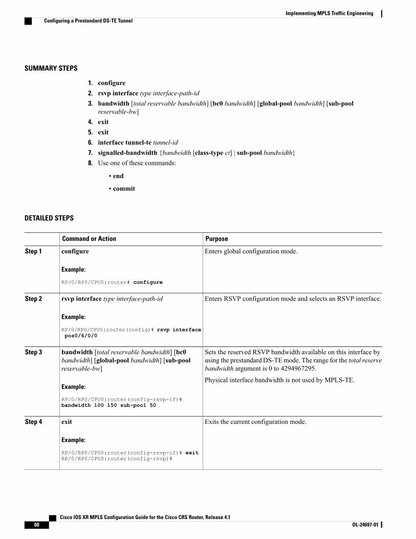
SUMMARY STEPS
1. configure2. rsvp interface type interface-path-id3. bandwidth [total reservable bandwidth] [bc0 bandwidth] [global-pool bandwidth] [sub-pool
reservable-bw]4. exit5. exit6. interface tunnel-te tunnel-id7. signalled-bandwidth {bandwidth [class-type ct] | sub-pool bandwidth}8. Use one of these commands:
• end
• commit
DETAILED STEPS
PurposeCommand or Action
Enters global configuration mode.configure
Example:
RP/0/RP0/CPU0:router# configure
Step 1
Enters RSVP configuration mode and selects an RSVP interface.rsvp interface type interface-path-id
Example:
RP/0/RP0/CPU0:router(config)# rsvp interface
Step 2
pos0/6/0/0
Sets the reserved RSVP bandwidth available on this interface byusing the prestandard DS-TEmode. The range for the total reservebandwidth argument is 0 to 4294967295.
bandwidth [total reservable bandwidth] [bc0bandwidth] [global-pool bandwidth] [sub-poolreservable-bw]
Step 3
Example:
RP/0/RP0/CPU0:router(config-rsvp-if)#
Physical interface bandwidth is not used by MPLS-TE.
bandwidth 100 150 sub-pool 50
Exits the current configuration mode.exit
Example:
RP/0/RP0/CPU0:router(config-rsvp-if)# exit
Step 4
RP/0/RP0/CPU0:router(config-rsvp)#
Cisco IOS XR MPLS Configuration Guide for the Cisco CRS Router, Release 4.160 OL-24697-01
Implementing MPLS Traffic EngineeringConfiguring a Prestandard DS-TE Tunnel
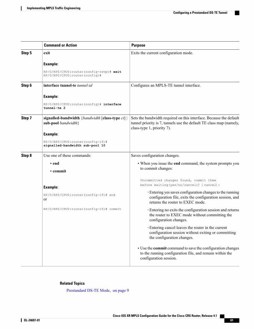
PurposeCommand or Action
Exits the current configuration mode.exit
Example:
RP/0/RP0/CPU0:router(config-rsvp)# exit
Step 5
RP/0/RP0/CPU0:router(config)#
Configures an MPLS-TE tunnel interface.interface tunnel-te tunnel-id
Example:
RP/0/RP0/CPU0:router(config)# interface
Step 6
tunnel-te 2
Sets the bandwidth required on this interface. Because the defaulttunnel priority is 7, tunnels use the default TE class map (namely,class-type 1, priority 7).
signalled-bandwidth {bandwidth [class-type ct] |sub-pool bandwidth}
Example:
RP/0/RP0/CPU0:router(config-if)#
Step 7
signalled-bandwidth sub-pool 10
Saves configuration changes.Use one of these commands:Step 8
• end •When you issue the end command, the system prompts youto commit changes:
Uncommitted changes found, commit thembefore exiting(yes/no/cancel)? [cancel]:
• commit
Example:
RP/0/RP0/CPU0:router(config-if)# end◦Entering yes saves configuration changes to the runningconfiguration file, exits the configuration session, andreturns the router to EXEC mode.
or
RP/0/RP0/CPU0:router(config-if)# commit ◦Entering no exits the configuration session and returnsthe router to EXEC mode without committing theconfiguration changes.
◦Entering cancel leaves the router in the currentconfiguration session without exiting or committingthe configuration changes.
• Use the commit command to save the configuration changesto the running configuration file, and remain within theconfiguration session.
Related Topics
Prestandard DS-TE Mode, on page 9
Cisco IOS XR MPLS Configuration Guide for the Cisco CRS Router, Release 4.1 OL-24697-01 61
Implementing MPLS Traffic EngineeringConfiguring a Prestandard DS-TE Tunnel
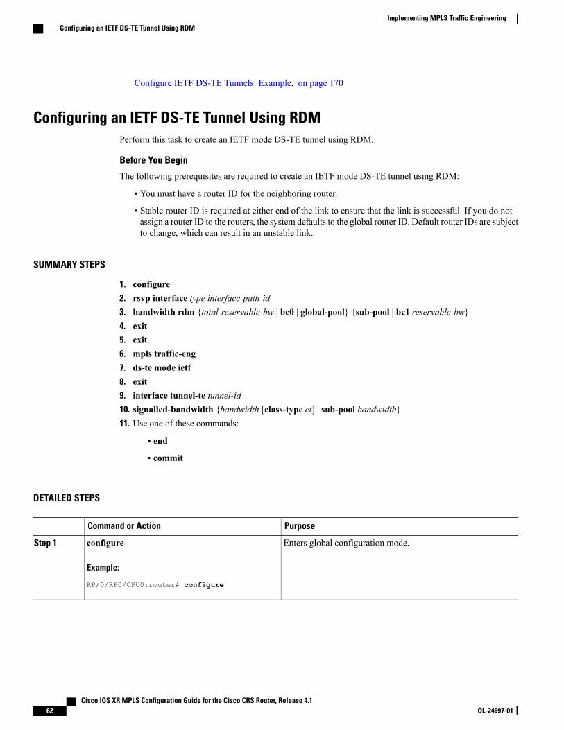
Configure IETF DS-TE Tunnels: Example, on page 170
Configuring an IETF DS-TE Tunnel Using RDMPerform this task to create an IETF mode DS-TE tunnel using RDM.
Before You Begin
The following prerequisites are required to create an IETF mode DS-TE tunnel using RDM:
• You must have a router ID for the neighboring router.
• Stable router ID is required at either end of the link to ensure that the link is successful. If you do notassign a router ID to the routers, the system defaults to the global router ID. Default router IDs are subjectto change, which can result in an unstable link.
SUMMARY STEPS
1. configure2. rsvp interface type interface-path-id3. bandwidth rdm {total-reservable-bw | bc0 | global-pool} {sub-pool | bc1 reservable-bw}4. exit5. exit6. mpls traffic-eng7. ds-te mode ietf8. exit9. interface tunnel-te tunnel-id10. signalled-bandwidth {bandwidth [class-type ct] | sub-pool bandwidth}11. Use one of these commands:
• end
• commit
DETAILED STEPS
PurposeCommand or Action
Enters global configuration mode.configure
Example:
RP/0/RP0/CPU0:router# configure
Step 1
Cisco IOS XR MPLS Configuration Guide for the Cisco CRS Router, Release 4.162 OL-24697-01
Implementing MPLS Traffic EngineeringConfiguring an IETF DS-TE Tunnel Using RDM
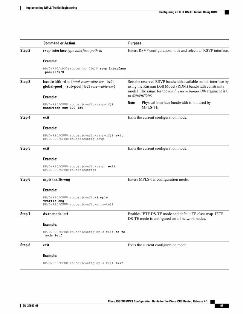
PurposeCommand or Action
Enters RSVP configuration mode and selects an RSVP interface.rsvp interface type interface-path-id
Example:
RP/0/RP0/CPU0:router(config)# rsvp interface
Step 2
pos0/6/0/0
Sets the reserved RSVP bandwidth available on this interface byusing the Russian Doll Model (RDM) bandwidth constraints
bandwidth rdm {total-reservable-bw | bc0 |global-pool} {sub-pool | bc1 reservable-bw}
Step 3
model. The range for the total reserve bandwidth argument is 0to 4294967295.Example:
RP/0/RP0/CPU0:router(config-rsvp-if)# Physical interface bandwidth is not used byMPLS-TE.
Notebandwidth rdm 100 150
Exits the current configuration mode.exit
Example:
RP/0/RP0/CPU0:router(config-rsvp-if)# exit
Step 4
RP/0/RP0/CPU0:router(config-rsvp)
Exits the current configuration mode.exit
Example:
RP/0/RP0/CPU0:router(config-rsvp) exit
Step 5
RP/0/RP0/CPU0:router(config)
Enters MPLS-TE configuration mode.mpls traffic-eng
Example:
RP/0/RP0/CPU0:router(config)# mpls
Step 6
traffic-engRP/0/RP0/CPU0:router(config-mpls-te)#
Enables IETF DS-TE mode and default TE class map. IETFDS-TE mode is configured on all network nodes.
ds-te mode ietf
Example:
RP/0/RP0/CPU0:router(config-mpls-te)# ds-te
Step 7
mode ietf
Exits the current configuration mode.exit
Example:
RP/0/RP0/CPU0:router(config-mpls-te)# exit
Step 8
Cisco IOS XR MPLS Configuration Guide for the Cisco CRS Router, Release 4.1 OL-24697-01 63
Implementing MPLS Traffic EngineeringConfiguring an IETF DS-TE Tunnel Using RDM
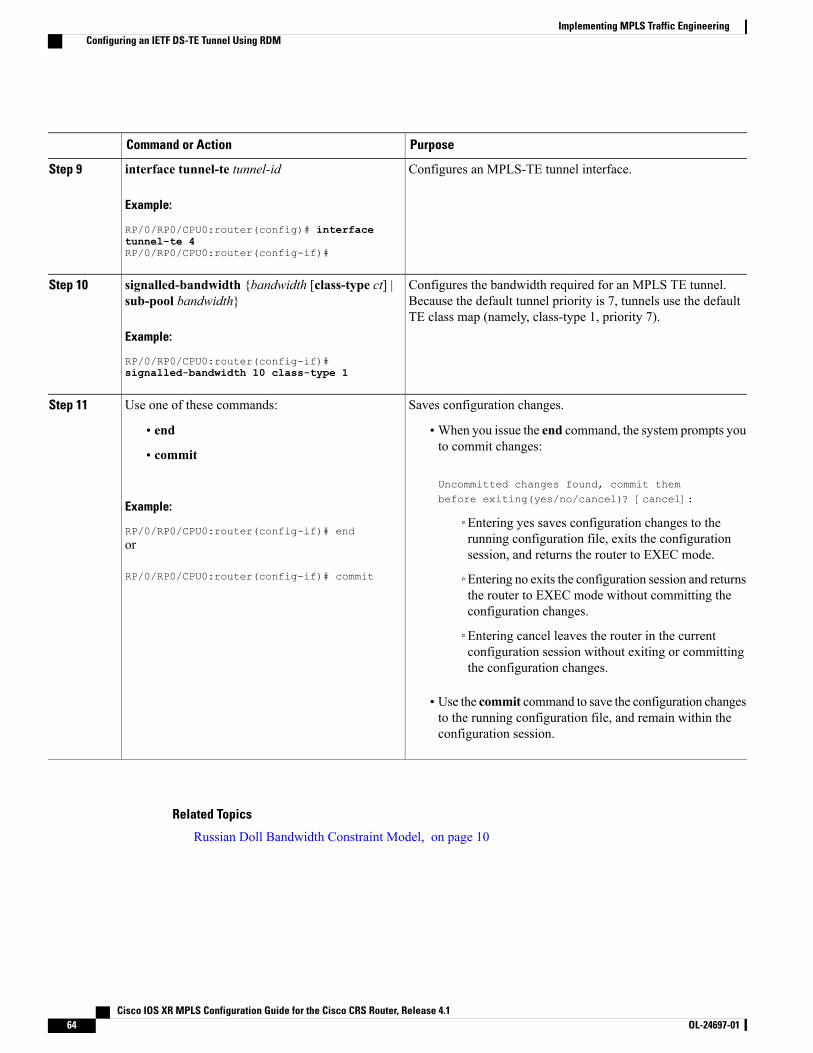
PurposeCommand or Action
Configures an MPLS-TE tunnel interface.interface tunnel-te tunnel-id
Example:
RP/0/RP0/CPU0:router(config)# interface
Step 9
tunnel-te 4RP/0/RP0/CPU0:router(config-if)#
Configures the bandwidth required for an MPLS TE tunnel.Because the default tunnel priority is 7, tunnels use the defaultTE class map (namely, class-type 1, priority 7).
signalled-bandwidth {bandwidth [class-type ct] |sub-pool bandwidth}
Example:
RP/0/RP0/CPU0:router(config-if)#
Step 10
signalled-bandwidth 10 class-type 1
Saves configuration changes.Use one of these commands:Step 11
• end •When you issue the end command, the system prompts youto commit changes:
Uncommitted changes found, commit thembefore exiting(yes/no/cancel)? [cancel]:
• commit
Example:
RP/0/RP0/CPU0:router(config-if)# end◦Entering yes saves configuration changes to therunning configuration file, exits the configurationsession, and returns the router to EXEC mode.
or
RP/0/RP0/CPU0:router(config-if)# commit ◦Entering no exits the configuration session and returnsthe router to EXEC mode without committing theconfiguration changes.
◦Entering cancel leaves the router in the currentconfiguration session without exiting or committingthe configuration changes.
• Use the commit command to save the configuration changesto the running configuration file, and remain within theconfiguration session.
Related Topics
Russian Doll Bandwidth Constraint Model, on page 10
Cisco IOS XR MPLS Configuration Guide for the Cisco CRS Router, Release 4.164 OL-24697-01
Implementing MPLS Traffic EngineeringConfiguring an IETF DS-TE Tunnel Using RDM
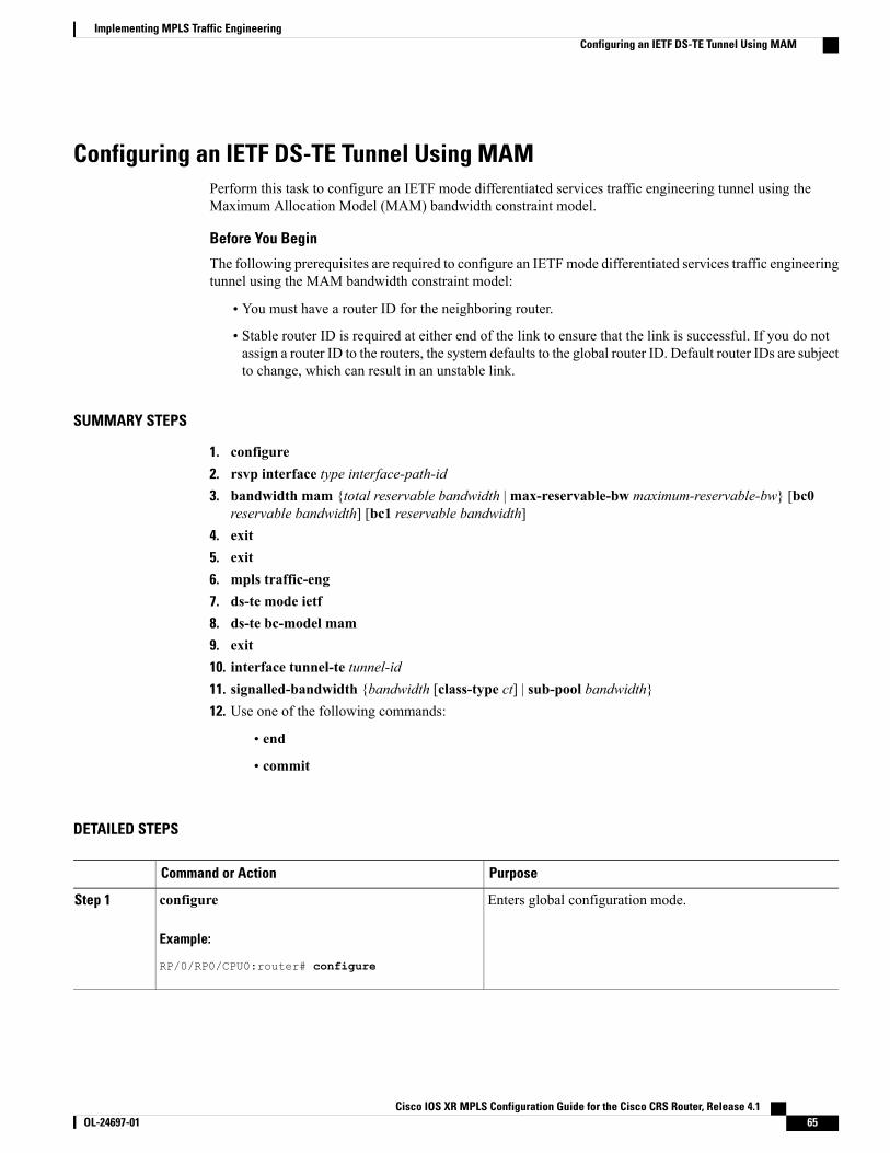
Configuring an IETF DS-TE Tunnel Using MAMPerform this task to configure an IETF mode differentiated services traffic engineering tunnel using theMaximum Allocation Model (MAM) bandwidth constraint model.
Before You Begin
The following prerequisites are required to configure an IETFmode differentiated services traffic engineeringtunnel using the MAM bandwidth constraint model:
• You must have a router ID for the neighboring router.
• Stable router ID is required at either end of the link to ensure that the link is successful. If you do notassign a router ID to the routers, the system defaults to the global router ID. Default router IDs are subjectto change, which can result in an unstable link.
SUMMARY STEPS
1. configure2. rsvp interface type interface-path-id3. bandwidth mam {total reservable bandwidth |max-reservable-bw maximum-reservable-bw} [bc0
reservable bandwidth] [bc1 reservable bandwidth]4. exit5. exit6. mpls traffic-eng7. ds-te mode ietf8. ds-te bc-model mam9. exit10. interface tunnel-te tunnel-id11. signalled-bandwidth {bandwidth [class-type ct] | sub-pool bandwidth}12. Use one of the following commands:
• end
• commit
DETAILED STEPS
PurposeCommand or Action
Enters global configuration mode.configure
Example:
RP/0/RP0/CPU0:router# configure
Step 1
Cisco IOS XR MPLS Configuration Guide for the Cisco CRS Router, Release 4.1 OL-24697-01 65
Implementing MPLS Traffic EngineeringConfiguring an IETF DS-TE Tunnel Using MAM
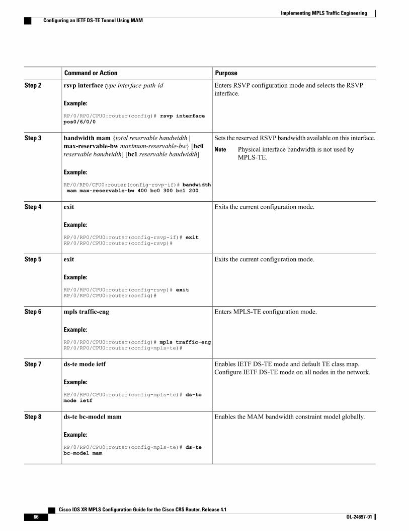
PurposeCommand or Action
Enters RSVP configuration mode and selects the RSVPinterface.
rsvp interface type interface-path-id
Example:
RP/0/RP0/CPU0:router(config)# rsvp interface
Step 2
pos0/6/0/0
Sets the reserved RSVP bandwidth available on this interface.bandwidth mam {total reservable bandwidth |max-reservable-bw maximum-reservable-bw} [bc0reservable bandwidth] [bc1 reservable bandwidth]
Step 3
Physical interface bandwidth is not used byMPLS-TE.
Note
Example:
RP/0/RP0/CPU0:router(config-rsvp-if)# bandwidthmam max-reservable-bw 400 bc0 300 bc1 200
Exits the current configuration mode.exit
Example:
RP/0/RP0/CPU0:router(config-rsvp-if)# exit
Step 4
RP/0/RP0/CPU0:router(config-rsvp)#
Exits the current configuration mode.exit
Example:
RP/0/RP0/CPU0:router(config-rsvp)# exit
Step 5
RP/0/RP0/CPU0:router(config)#
Enters MPLS-TE configuration mode.mpls traffic-eng
Example:
RP/0/RP0/CPU0:router(config)# mpls traffic-eng
Step 6
RP/0/RP0/CPU0:router(config-mpls-te)#
Enables IETF DS-TE mode and default TE class map.Configure IETF DS-TE mode on all nodes in the network.
ds-te mode ietf
Example:
RP/0/RP0/CPU0:router(config-mpls-te)# ds-te
Step 7
mode ietf
Enables the MAM bandwidth constraint model globally.ds-te bc-model mam
Example:
RP/0/RP0/CPU0:router(config-mpls-te)# ds-te
Step 8
bc-model mam
Cisco IOS XR MPLS Configuration Guide for the Cisco CRS Router, Release 4.166 OL-24697-01
Implementing MPLS Traffic EngineeringConfiguring an IETF DS-TE Tunnel Using MAM
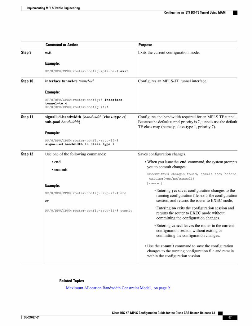
PurposeCommand or Action
Exits the current configuration mode.exit
Example:
RP/0/RP0/CPU0:router(config-mpls-te)# exit
Step 9
Configures an MPLS-TE tunnel interface.interface tunnel-te tunnel-id
Example:
RP/0/RP0/CPU0:router(config)# interface
Step 10
tunnel-te 4RP/0/RP0/CPU0:router(config-if)#
Configures the bandwidth required for an MPLS TE tunnel.Because the default tunnel priority is 7, tunnels use the defaultTE class map (namely, class-type 1, priority 7).
signalled-bandwidth {bandwidth [class-type ct] |sub-pool bandwidth}
Example:
RP/0/RP0/CPU0:router(config-rsvp-if)#
Step 11
signalled-bandwidth 10 class-type 1
Saves configuration changes.Use one of the following commands:Step 12
• end •When you issue the end command, the system promptsyou to commit changes:
Uncommitted changes found, commit them beforeexiting(yes/no/cancel)?[cancel]:
• commit
Example:
RP/0/RP0/CPU0:router(config-rsvp-if)# end◦Entering yes saves configuration changes to therunning configuration file, exits the configurationsession, and returns the router to EXEC mode.or
RP/0/RP0/CPU0:router(config-rsvp-if)# commit◦Entering no exits the configuration session andreturns the router to EXEC mode withoutcommitting the configuration changes.
◦Entering cancel leaves the router in the currentconfiguration session without exiting orcommitting the configuration changes.
• Use the commit command to save the configurationchanges to the running configuration file and remainwithin the configuration session.
Related Topics
Maximum Allocation Bandwidth Constraint Model, on page 9
Cisco IOS XR MPLS Configuration Guide for the Cisco CRS Router, Release 4.1 OL-24697-01 67
Implementing MPLS Traffic EngineeringConfiguring an IETF DS-TE Tunnel Using MAM
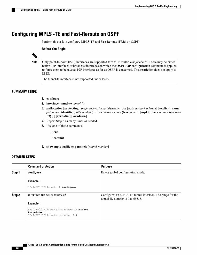
Configuring MPLS -TE and Fast-Reroute on OSPFPerform this task to configure MPLS-TE and Fast Reroute (FRR) on OSPF.
Before You Begin
Only point-to-point (P2P) interfaces are supported for OSPF multiple adjacencies. These may be eithernative P2P interfaces or broadcast interfaces on which theOSPF P2P configuration command is appliedto force them to behave as P2P interfaces as far as OSPF is concerned. This restriction does not apply toIS-IS.
The tunnel-te interface is not supported under IS-IS.
Note
SUMMARY STEPS
1. configure2. interface tunnel-te tunnel-id3. path-option [protecting ] preference-priority {dynamic [pce [address ipv4 address] | explicit {name
pathname | identifier path-number } } [isis instance name {level level} ] [ospf instance name {area areaID} ] ] [verbatim] [lockdown]
4. Repeat Step 3 as many times as needed.5. Use one of these commands:
• end
• commit
6. show mpls traffic-eng tunnels [tunnel-number]
DETAILED STEPS
PurposeCommand or Action
Enters global configuration mode.configure
Example:
RP/0/RP0/CPU0:router# configure
Step 1
Configures an MPLS-TE tunnel interface. The range for thetunnel ID number is 0 to 65535.
interface tunnel-te tunnel-id
Example:
RP/0/RP0/CPU0:router(config)# interface
Step 2
tunnel-te 1RP/0/RP0/CPU0:router(config-if)#
Cisco IOS XR MPLS Configuration Guide for the Cisco CRS Router, Release 4.168 OL-24697-01
Implementing MPLS Traffic EngineeringConfiguring MPLS -TE and Fast-Reroute on OSPF
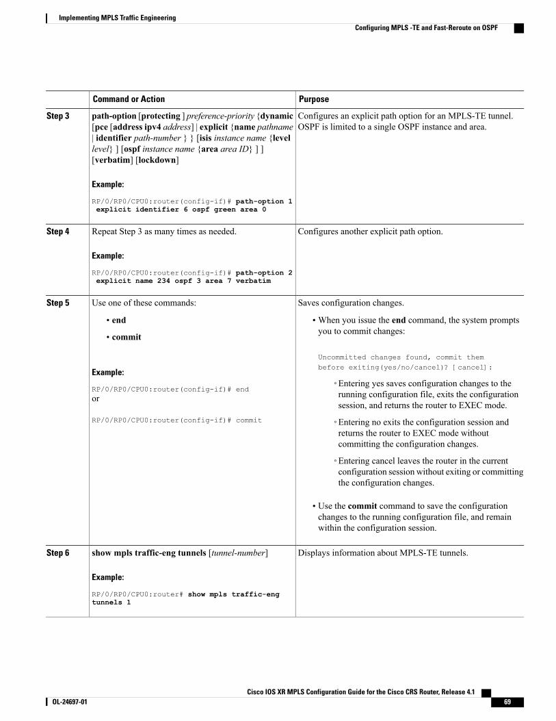
PurposeCommand or Action
Configures an explicit path option for an MPLS-TE tunnel.OSPF is limited to a single OSPF instance and area.
path-option [protecting ] preference-priority {dynamic[pce [address ipv4 address] | explicit {name pathname| identifier path-number } } [isis instance name {level
Step 3
level} ] [ospf instance name {area area ID} ] ][verbatim] [lockdown]
Example:
RP/0/RP0/CPU0:router(config-if)# path-option 1explicit identifier 6 ospf green area 0
Configures another explicit path option.Repeat Step 3 as many times as needed.
Example:
RP/0/RP0/CPU0:router(config-if)# path-option 2
Step 4
explicit name 234 ospf 3 area 7 verbatim
Saves configuration changes.Use one of these commands:Step 5
• end •When you issue the end command, the system promptsyou to commit changes:
Uncommitted changes found, commit thembefore exiting(yes/no/cancel)? [cancel]:
• commit
Example:
RP/0/RP0/CPU0:router(config-if)# end◦Entering yes saves configuration changes to therunning configuration file, exits the configurationsession, and returns the router to EXEC mode.
or
RP/0/RP0/CPU0:router(config-if)# commit ◦Entering no exits the configuration session andreturns the router to EXEC mode withoutcommitting the configuration changes.
◦Entering cancel leaves the router in the currentconfiguration session without exiting or committingthe configuration changes.
• Use the commit command to save the configurationchanges to the running configuration file, and remainwithin the configuration session.
Displays information about MPLS-TE tunnels.show mpls traffic-eng tunnels [tunnel-number]
Example:
RP/0/RP0/CPU0:router# show mpls traffic-eng
Step 6
tunnels 1
Cisco IOS XR MPLS Configuration Guide for the Cisco CRS Router, Release 4.1 OL-24697-01 69
Implementing MPLS Traffic EngineeringConfiguring MPLS -TE and Fast-Reroute on OSPF
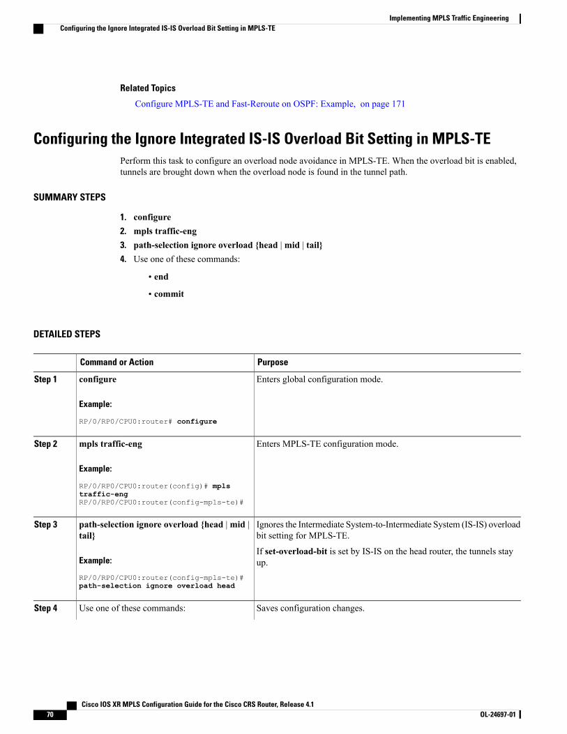
Related Topics
Configure MPLS-TE and Fast-Reroute on OSPF: Example, on page 171
Configuring the Ignore Integrated IS-IS Overload Bit Setting in MPLS-TEPerform this task to configure an overload node avoidance in MPLS-TE. When the overload bit is enabled,tunnels are brought down when the overload node is found in the tunnel path.
SUMMARY STEPS
1. configure2. mpls traffic-eng3. path-selection ignore overload {head |mid | tail}4. Use one of these commands:
• end
• commit
DETAILED STEPS
PurposeCommand or Action
Enters global configuration mode.configure
Example:
RP/0/RP0/CPU0:router# configure
Step 1
Enters MPLS-TE configuration mode.mpls traffic-eng
Example:
RP/0/RP0/CPU0:router(config)# mpls
Step 2
traffic-engRP/0/RP0/CPU0:router(config-mpls-te)#
Ignores the Intermediate System-to-Intermediate System (IS-IS) overloadbit setting for MPLS-TE.
path-selection ignore overload {head |mid |tail}
Step 3
Example:
RP/0/RP0/CPU0:router(config-mpls-te)#
If set-overload-bit is set by IS-IS on the head router, the tunnels stayup.
path-selection ignore overload head
Saves configuration changes.Use one of these commands:Step 4
Cisco IOS XR MPLS Configuration Guide for the Cisco CRS Router, Release 4.170 OL-24697-01
Implementing MPLS Traffic EngineeringConfiguring the Ignore Integrated IS-IS Overload Bit Setting in MPLS-TE
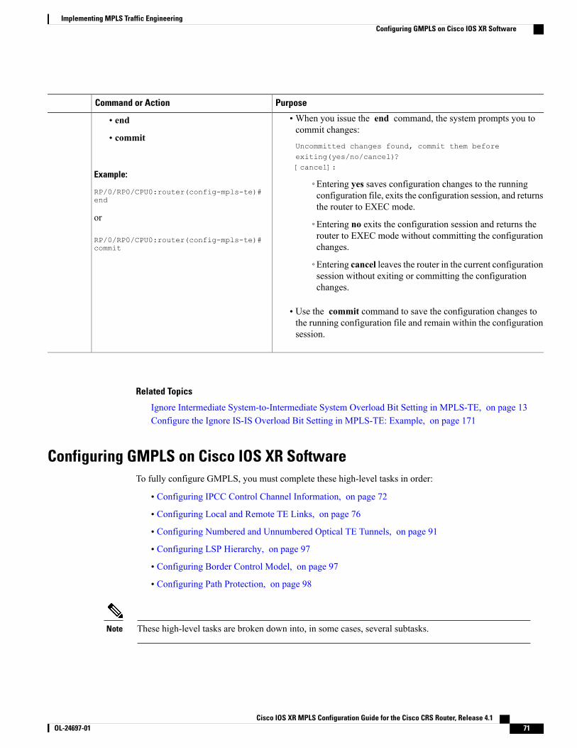
PurposeCommand or Action
•When you issue the end command, the system prompts you tocommit changes:
Uncommitted changes found, commit them beforeexiting(yes/no/cancel)?[cancel]:
• end
• commit
Example:
RP/0/RP0/CPU0:router(config-mpls-te)#◦Entering yes saves configuration changes to the runningconfiguration file, exits the configuration session, and returnsthe router to EXEC mode.
end
or
RP/0/RP0/CPU0:router(config-mpls-te)#
◦Entering no exits the configuration session and returns therouter to EXEC mode without committing the configurationchanges.commit
◦Entering cancel leaves the router in the current configurationsession without exiting or committing the configurationchanges.
• Use the commit command to save the configuration changes tothe running configuration file and remain within the configurationsession.
Related Topics
Ignore Intermediate System-to-Intermediate System Overload Bit Setting in MPLS-TE, on page 13Configure the Ignore IS-IS Overload Bit Setting in MPLS-TE: Example, on page 171
Configuring GMPLS on Cisco IOS XR SoftwareTo fully configure GMPLS, you must complete these high-level tasks in order:
• Configuring IPCC Control Channel Information, on page 72
• Configuring Local and Remote TE Links, on page 76
• Configuring Numbered and Unnumbered Optical TE Tunnels, on page 91
• Configuring LSP Hierarchy, on page 97
• Configuring Border Control Model, on page 97
• Configuring Path Protection, on page 98
These high-level tasks are broken down into, in some cases, several subtasks.Note
Cisco IOS XR MPLS Configuration Guide for the Cisco CRS Router, Release 4.1 OL-24697-01 71
Implementing MPLS Traffic EngineeringConfiguring GMPLS on Cisco IOS XR Software
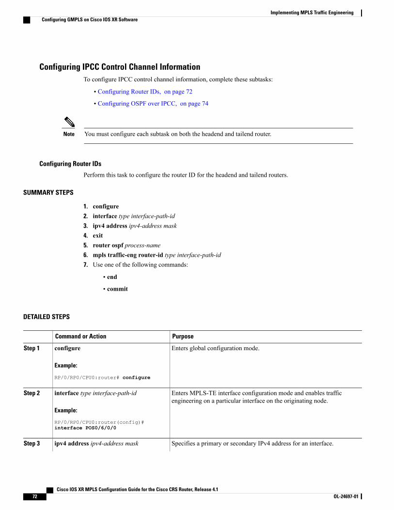
Configuring IPCC Control Channel InformationTo configure IPCC control channel information, complete these subtasks:
• Configuring Router IDs, on page 72
• Configuring OSPF over IPCC, on page 74
You must configure each subtask on both the headend and tailend router.Note
Configuring Router IDs
Perform this task to configure the router ID for the headend and tailend routers.
SUMMARY STEPS
1. configure2. interface type interface-path-id3. ipv4 address ipv4-address mask4. exit5. router ospf process-name6. mpls traffic-eng router-id type interface-path-id7. Use one of the following commands:
• end
• commit
DETAILED STEPS
PurposeCommand or Action
Enters global configuration mode.configure
Example:
RP/0/RP0/CPU0:router# configure
Step 1
Enters MPLS-TE interface configuration mode and enables trafficengineering on a particular interface on the originating node.
interface type interface-path-id
Example:
RP/0/RP0/CPU0:router(config)#
Step 2
interface POS0/6/0/0
Specifies a primary or secondary IPv4 address for an interface.ipv4 address ipv4-address maskStep 3
Cisco IOS XR MPLS Configuration Guide for the Cisco CRS Router, Release 4.172 OL-24697-01
Implementing MPLS Traffic EngineeringConfiguring GMPLS on Cisco IOS XR Software
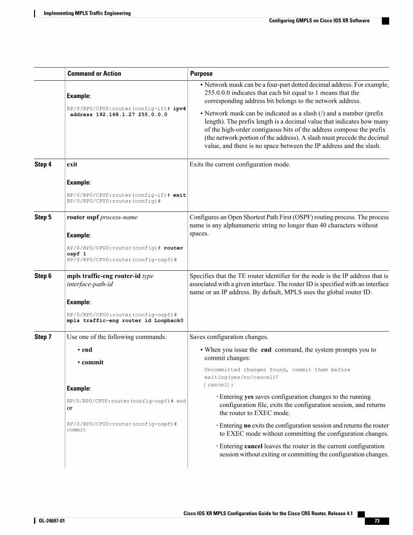
PurposeCommand or Action
Example:
RP/0/RP0/CPU0:router(config-if)# ipv4
• Networkmask can be a four-part dotted decimal address. For example,255.0.0.0 indicates that each bit equal to 1 means that thecorresponding address bit belongs to the network address.
• Network mask can be indicated as a slash (/) and a number (prefixlength). The prefix length is a decimal value that indicates how many
address 192.168.1.27 255.0.0.0
of the high-order contiguous bits of the address compose the prefix(the network portion of the address). A slash must precede the decimalvalue, and there is no space between the IP address and the slash.
Exits the current configuration mode.exit
Example:
RP/0/RP0/CPU0:router(config-if)# exit
Step 4
RP/0/RP0/CPU0:router(config)#
Configures an Open Shortest Path First (OSPF) routing process. The processname is any alphanumeric string no longer than 40 characters withoutspaces.
router ospf process-name
Example:
RP/0/RP0/CPU0:router(config)# router
Step 5
ospf 1RP/0/RP0/CPU0:router(config-ospf)#
Specifies that the TE router identifier for the node is the IP address that isassociated with a given interface. The router ID is specified with an interfacename or an IP address. By default, MPLS uses the global router ID.
mpls traffic-eng router-id typeinterface-path-id
Example:
RP/0/RP0/CPU0:router(config-ospf)#
Step 6
mpls traffic-eng router id Loopback0
Saves configuration changes.Use one of the following commands:Step 7
• end •When you issue the end command, the system prompts you tocommit changes:
Uncommitted changes found, commit them beforeexiting(yes/no/cancel)?[cancel]:
• commit
Example:
RP/0/RP0/CPU0:router(config-ospf)# end◦Entering yes saves configuration changes to the runningconfiguration file, exits the configuration session, and returnsthe router to EXEC mode.
or
RP/0/RP0/CPU0:router(config-ospf)#commit
◦Entering no exits the configuration session and returns the routerto EXEC mode without committing the configuration changes.
◦Entering cancel leaves the router in the current configurationsession without exiting or committing the configuration changes.
Cisco IOS XR MPLS Configuration Guide for the Cisco CRS Router, Release 4.1 OL-24697-01 73
Implementing MPLS Traffic EngineeringConfiguring GMPLS on Cisco IOS XR Software
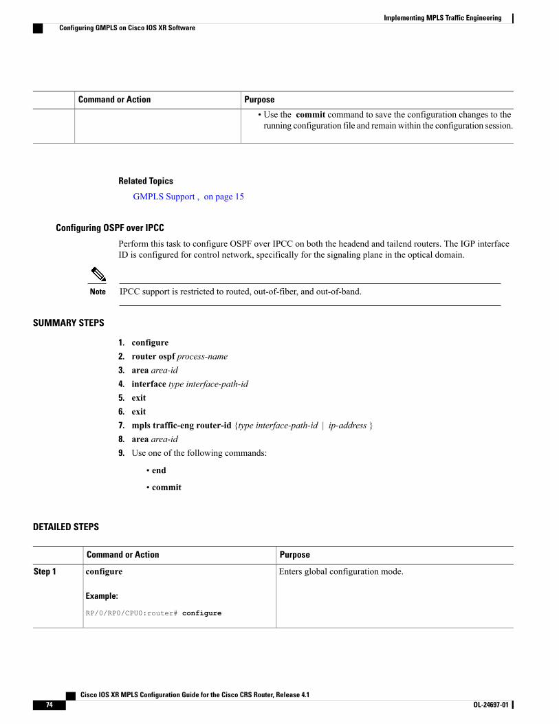
PurposeCommand or Action
• Use the commit command to save the configuration changes to therunning configuration file and remain within the configuration session.
Related Topics
GMPLS Support , on page 15
Configuring OSPF over IPCC
Perform this task to configure OSPF over IPCC on both the headend and tailend routers. The IGP interfaceID is configured for control network, specifically for the signaling plane in the optical domain.
IPCC support is restricted to routed, out-of-fiber, and out-of-band.Note
SUMMARY STEPS
1. configure2. router ospf process-name3. area area-id4. interface type interface-path-id5. exit6. exit7. mpls traffic-eng router-id {type interface-path-id | ip-address }8. area area-id9. Use one of the following commands:
• end
• commit
DETAILED STEPS
PurposeCommand or Action
Enters global configuration mode.configure
Example:
RP/0/RP0/CPU0:router# configure
Step 1
Cisco IOS XR MPLS Configuration Guide for the Cisco CRS Router, Release 4.174 OL-24697-01
Implementing MPLS Traffic EngineeringConfiguring GMPLS on Cisco IOS XR Software
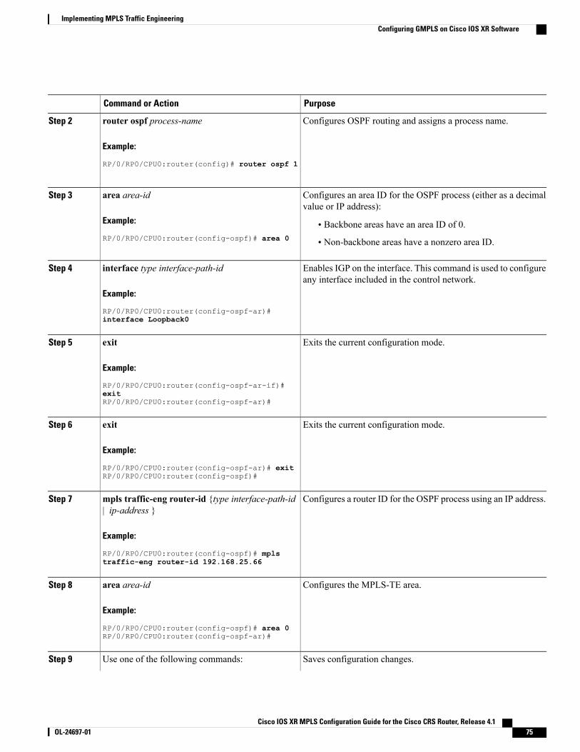
PurposeCommand or Action
Configures OSPF routing and assigns a process name.router ospf process-name
Example:
RP/0/RP0/CPU0:router(config)# router ospf 1
Step 2
Configures an area ID for the OSPF process (either as a decimalvalue or IP address):
area area-id
Example:
RP/0/RP0/CPU0:router(config-ospf)# area 0
Step 3
• Backbone areas have an area ID of 0.
• Non-backbone areas have a nonzero area ID.
Enables IGP on the interface. This command is used to configureany interface included in the control network.
interface type interface-path-id
Example:
RP/0/RP0/CPU0:router(config-ospf-ar)#
Step 4
interface Loopback0
Exits the current configuration mode.exit
Example:
RP/0/RP0/CPU0:router(config-ospf-ar-if)#
Step 5
exitRP/0/RP0/CPU0:router(config-ospf-ar)#
Exits the current configuration mode.exit
Example:
RP/0/RP0/CPU0:router(config-ospf-ar)# exit
Step 6
RP/0/RP0/CPU0:router(config-ospf)#
Configures a router ID for the OSPF process using an IP address.mpls traffic-eng router-id {type interface-path-id| ip-address }
Step 7
Example:
RP/0/RP0/CPU0:router(config-ospf)# mplstraffic-eng router-id 192.168.25.66
Configures the MPLS-TE area.area area-id
Example:
RP/0/RP0/CPU0:router(config-ospf)# area 0
Step 8
RP/0/RP0/CPU0:router(config-ospf-ar)#
Saves configuration changes.Use one of the following commands:Step 9
Cisco IOS XR MPLS Configuration Guide for the Cisco CRS Router, Release 4.1 OL-24697-01 75
Implementing MPLS Traffic EngineeringConfiguring GMPLS on Cisco IOS XR Software
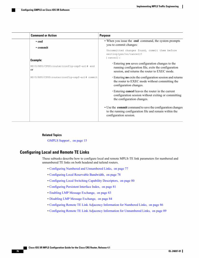
PurposeCommand or Action
•When you issue the end command, the system promptsyou to commit changes:
Uncommitted changes found, commit them beforeexiting(yes/no/cancel)?[cancel]:
• end
• commit
Example:
RP/0/RP0/CPU0:router(config-ospf-ar)# end◦Entering yes saves configuration changes to therunning configuration file, exits the configurationsession, and returns the router to EXEC mode.or
RP/0/RP0/CPU0:router(config-ospf-ar)# commit ◦Entering no exits the configuration session and returnsthe router to EXEC mode without committing theconfiguration changes.
◦Entering cancel leaves the router in the currentconfiguration session without exiting or committingthe configuration changes.
• Use the commit command to save the configuration changesto the running configuration file and remain within theconfiguration session.
Related Topics
GMPLS Support , on page 15
Configuring Local and Remote TE LinksThese subtasks describe how to configure local and remote MPLS-TE link parameters for numbered andunnumbered TE links on both headend and tailend routers.
• Configuring Numbered and Unnumbered Links, on page 77
• Configuring Local Reservable Bandwidth, on page 78
• Configuring Local Switching Capability Descriptors, on page 80
• Configuring Persistent Interface Index, on page 81
• Enabling LMP Message Exchange, on page 83
• Disabling LMP Message Exchange, on page 84
• Configuring Remote TE Link Adjacency Information for Numbered Links, on page 86
• Configuring Remote TE Link Adjacency Information for Unnumbered Links, on page 89
Cisco IOS XR MPLS Configuration Guide for the Cisco CRS Router, Release 4.176 OL-24697-01
Implementing MPLS Traffic EngineeringConfiguring GMPLS on Cisco IOS XR Software
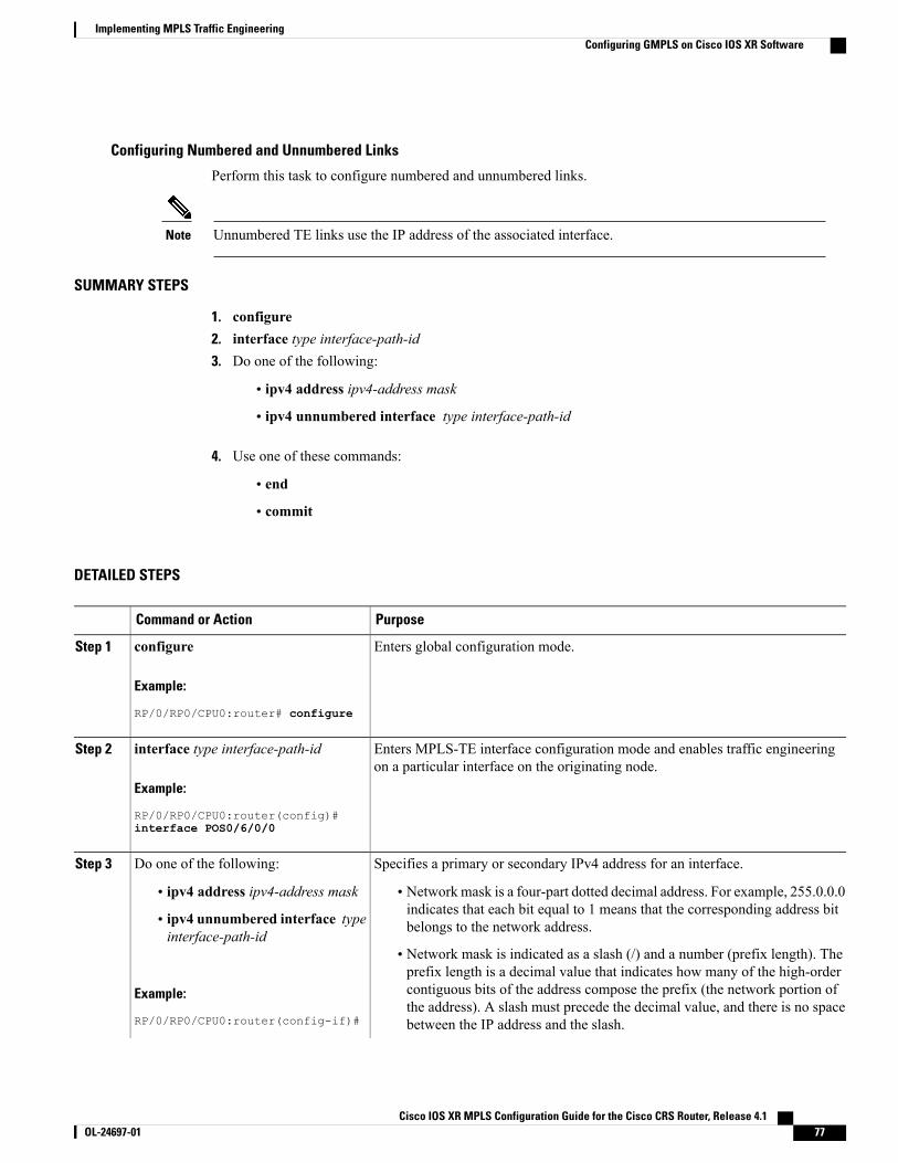
Configuring Numbered and Unnumbered Links
Perform this task to configure numbered and unnumbered links.
Unnumbered TE links use the IP address of the associated interface.Note
SUMMARY STEPS
1. configure2. interface type interface-path-id3. Do one of the following:
• ipv4 address ipv4-address mask
• ipv4 unnumbered interface type interface-path-id
4. Use one of these commands:
• end
• commit
DETAILED STEPS
PurposeCommand or Action
Enters global configuration mode.configure
Example:
RP/0/RP0/CPU0:router# configure
Step 1
Enters MPLS-TE interface configuration mode and enables traffic engineeringon a particular interface on the originating node.
interface type interface-path-id
Example:
RP/0/RP0/CPU0:router(config)#
Step 2
interface POS0/6/0/0
Specifies a primary or secondary IPv4 address for an interface.Do one of the following:Step 3
• ipv4 address ipv4-address mask • Network mask is a four-part dotted decimal address. For example, 255.0.0.0indicates that each bit equal to 1 means that the corresponding address bitbelongs to the network address.• ipv4 unnumbered interface type
interface-path-id• Network mask is indicated as a slash (/) and a number (prefix length). Theprefix length is a decimal value that indicates how many of the high-order
Example:
RP/0/RP0/CPU0:router(config-if)#
contiguous bits of the address compose the prefix (the network portion ofthe address). A slash must precede the decimal value, and there is no spacebetween the IP address and the slash.
Cisco IOS XR MPLS Configuration Guide for the Cisco CRS Router, Release 4.1 OL-24697-01 77
Implementing MPLS Traffic EngineeringConfiguring GMPLS on Cisco IOS XR Software
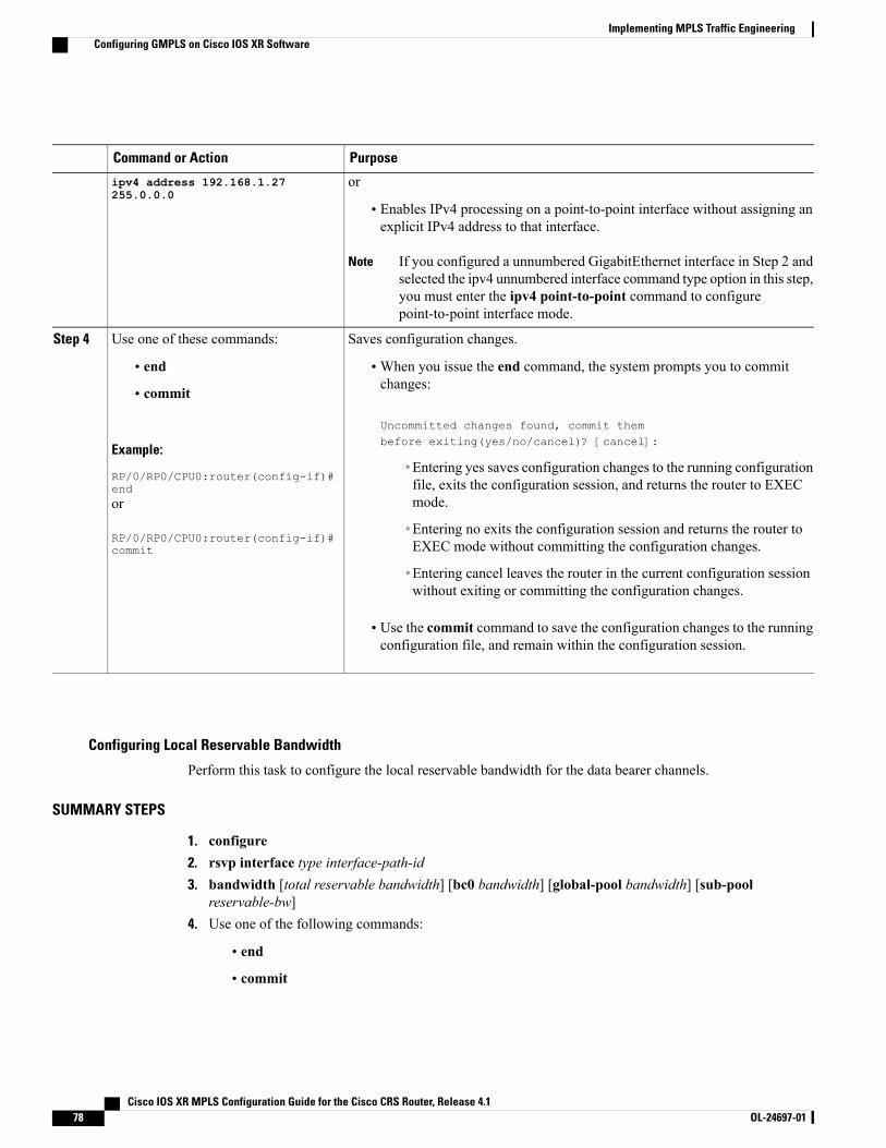
PurposeCommand or Action
oripv4 address 192.168.1.27255.0.0.0
• Enables IPv4 processing on a point-to-point interface without assigning anexplicit IPv4 address to that interface.
If you configured a unnumbered GigabitEthernet interface in Step 2 andselected the ipv4 unnumbered interface command type option in this step,you must enter the ipv4 point-to-point command to configurepoint-to-point interface mode.
Note
Saves configuration changes.Use one of these commands:Step 4
• end •When you issue the end command, the system prompts you to commitchanges:
Uncommitted changes found, commit thembefore exiting(yes/no/cancel)? [cancel]:
• commit
Example:
RP/0/RP0/CPU0:router(config-if)#end
◦Entering yes saves configuration changes to the running configurationfile, exits the configuration session, and returns the router to EXECmode.or
RP/0/RP0/CPU0:router(config-if)#commit
◦Entering no exits the configuration session and returns the router toEXEC mode without committing the configuration changes.
◦Entering cancel leaves the router in the current configuration sessionwithout exiting or committing the configuration changes.
• Use the commit command to save the configuration changes to the runningconfiguration file, and remain within the configuration session.
Configuring Local Reservable Bandwidth
Perform this task to configure the local reservable bandwidth for the data bearer channels.
SUMMARY STEPS
1. configure2. rsvp interface type interface-path-id3. bandwidth [total reservable bandwidth] [bc0 bandwidth] [global-pool bandwidth] [sub-pool
reservable-bw]4. Use one of the following commands:
• end
• commit
Cisco IOS XR MPLS Configuration Guide for the Cisco CRS Router, Release 4.178 OL-24697-01
Implementing MPLS Traffic EngineeringConfiguring GMPLS on Cisco IOS XR Software
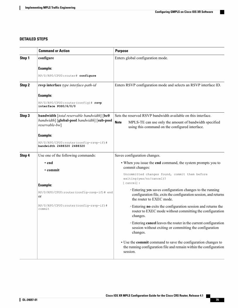
DETAILED STEPS
PurposeCommand or Action
Enters global configuration mode.configure
Example:
RP/0/RP0/CPU0:router# configure
Step 1
Enters RSVP configuration mode and selects an RSVP interface ID.rsvp interface type interface-path-id
Example:
RP/0/RP0/CPU0:router(config)# rsvp
Step 2
interface POS0/6/0/0
Sets the reserved RSVP bandwidth available on this interface.bandwidth [total reservable bandwidth] [bc0bandwidth] [global-pool bandwidth] [sub-poolreservable-bw]
Step 3
MPLS-TE can use only the amount of bandwidth specifiedusing this command on the configured interface.
Note
Example:
RP/0/RP0/CPU0:router(config-rsvp-if)#bandwidth 2488320 2488320
Saves configuration changes.Use one of the following commands:Step 4
• end •When you issue the end command, the system prompts you tocommit changes:
Uncommitted changes found, commit them beforeexiting(yes/no/cancel)?[cancel]:
• commit
Example:
RP/0/RP0/CPU0:router(config-rsvp-if)# end◦Entering yes saves configuration changes to the runningconfiguration file, exits the configuration session, and returnsthe router to EXEC mode.
or
RP/0/RP0/CPU0:router(config-rsvp-if)#commit
◦Entering no exits the configuration session and returns therouter to EXECmode without committing the configurationchanges.
◦Entering cancel leaves the router in the current configurationsession without exiting or committing the configurationchanges.
• Use the commit command to save the configuration changes tothe running configuration file and remain within the configurationsession.
Cisco IOS XR MPLS Configuration Guide for the Cisco CRS Router, Release 4.1 OL-24697-01 79
Implementing MPLS Traffic EngineeringConfiguring GMPLS on Cisco IOS XR Software
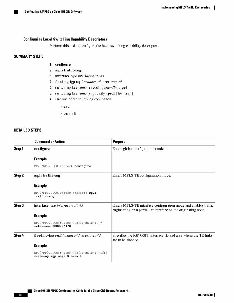
Configuring Local Switching Capability Descriptors
Perform this task to configure the local switching capability descriptor.
SUMMARY STEPS
1. configure2. mpls traffic-eng3. interface type interface-path-id4. flooding-igp ospf instance-id area area-id5. switching key value [encoding encoding type]6. switching key value [capability {psc1 | lsc | fsc} ]7. Use one of the following commands:
• end
• commit
DETAILED STEPS
PurposeCommand or Action
Enters global configuration mode.configure
Example:
RP/0/RP0/CPU0:router# configure
Step 1
Enters MPLS-TE configuration mode.mpls traffic-eng
Example:
RP/0/RP0/CPU0:router(config)# mpls
Step 2
traffic-eng
Enters MPLS-TE interface configuration mode and enables trafficengineering on a particular interface on the originating node.
interface type interface-path-id
Example:
RP/0/RP0/CPU0:router(config-mpls-te)#
Step 3
interface POS0/6/0/0
Specifies the IGP OSPF interface ID and area where the TE linksare to be flooded.
flooding-igp ospf instance-id area area-id
Example:
RP/0/RP0/CPU0:router(config-mpls-te-if)#
Step 4
flooding-igp ospf 0 area 1
Cisco IOS XR MPLS Configuration Guide for the Cisco CRS Router, Release 4.180 OL-24697-01
Implementing MPLS Traffic EngineeringConfiguring GMPLS on Cisco IOS XR Software
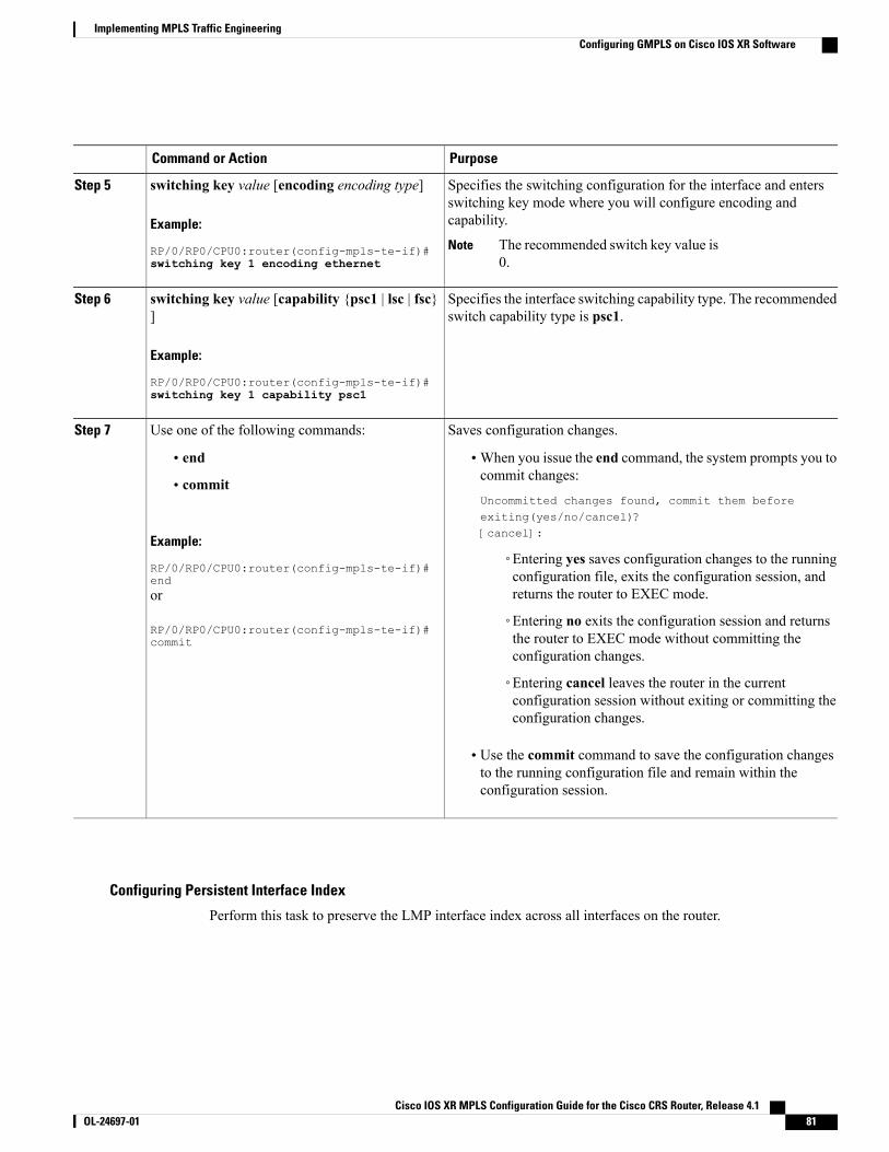
PurposeCommand or Action
Specifies the switching configuration for the interface and entersswitching key mode where you will configure encoding andcapability.
switching key value [encoding encoding type]
Example:
RP/0/RP0/CPU0:router(config-mpls-te-if)#
Step 5
The recommended switch key value is0.
Noteswitching key 1 encoding ethernet
Specifies the interface switching capability type. The recommendedswitch capability type is psc1.
switching key value [capability {psc1 | lsc | fsc}]
Example:
RP/0/RP0/CPU0:router(config-mpls-te-if)#
Step 6
switching key 1 capability psc1
Saves configuration changes.Use one of the following commands:Step 7
• end •When you issue the end command, the system prompts you tocommit changes:
Uncommitted changes found, commit them beforeexiting(yes/no/cancel)?[cancel]:
• commit
Example:
RP/0/RP0/CPU0:router(config-mpls-te-if)#end
◦Entering yes saves configuration changes to the runningconfiguration file, exits the configuration session, andreturns the router to EXEC mode.or
RP/0/RP0/CPU0:router(config-mpls-te-if)#commit
◦Entering no exits the configuration session and returnsthe router to EXEC mode without committing theconfiguration changes.
◦Entering cancel leaves the router in the currentconfiguration session without exiting or committing theconfiguration changes.
• Use the commit command to save the configuration changesto the running configuration file and remain within theconfiguration session.
Configuring Persistent Interface Index
Perform this task to preserve the LMP interface index across all interfaces on the router.
Cisco IOS XR MPLS Configuration Guide for the Cisco CRS Router, Release 4.1 OL-24697-01 81
Implementing MPLS Traffic EngineeringConfiguring GMPLS on Cisco IOS XR Software
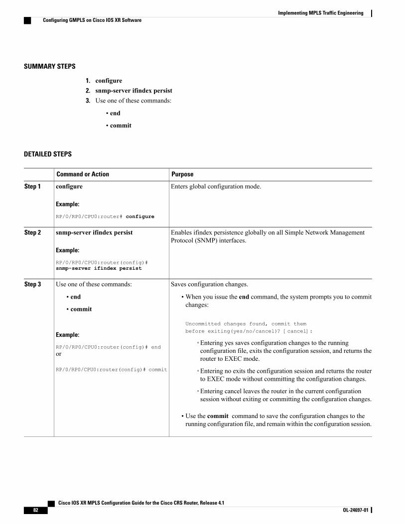
SUMMARY STEPS
1. configure2. snmp-server ifindex persist3. Use one of these commands:
• end
• commit
DETAILED STEPS
PurposeCommand or Action
Enters global configuration mode.configure
Example:
RP/0/RP0/CPU0:router# configure
Step 1
Enables ifindex persistence globally on all Simple Network ManagementProtocol (SNMP) interfaces.
snmp-server ifindex persist
Example:
RP/0/RP0/CPU0:router(config)#
Step 2
snmp-server ifindex persist
Saves configuration changes.Use one of these commands:Step 3
• end •When you issue the end command, the system prompts you to commitchanges:
Uncommitted changes found, commit thembefore exiting(yes/no/cancel)? [cancel]:
• commit
Example:
RP/0/RP0/CPU0:router(config)# end◦Entering yes saves configuration changes to the runningconfiguration file, exits the configuration session, and returns therouter to EXEC mode.
or
RP/0/RP0/CPU0:router(config)# commit ◦Entering no exits the configuration session and returns the routerto EXEC mode without committing the configuration changes.
◦Entering cancel leaves the router in the current configurationsession without exiting or committing the configuration changes.
• Use the commit command to save the configuration changes to therunning configuration file, and remain within the configuration session.
Cisco IOS XR MPLS Configuration Guide for the Cisco CRS Router, Release 4.182 OL-24697-01
Implementing MPLS Traffic EngineeringConfiguring GMPLS on Cisco IOS XR Software
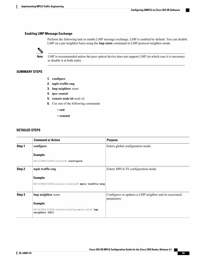
Enabling LMP Message Exchange
Perform the following task to enable LMP message exchange. LMP is enabled by default. You can disableLMP on a per neighbor basis using the lmp static command in LMP protocol neighbor mode.
LMP is recommended unless the peer optical device does not support LMP (in which case it is necessaryto disable it at both ends).
Note
SUMMARY STEPS
1. configure2. mpls traffic-eng3. lmp neighbor name4. ipcc routed5. remote node-id node-id6. Use one of the following commands:
• end
• commit
DETAILED STEPS
PurposeCommand or Action
Enters global configuration mode.configure
Example:
RP/0/RP0/CPU0:router# configure
Step 1
Enters MPLS-TE configuration mode.mpls traffic-eng
Example:
RP/0/RP0/CPU0:router(config)# mpls traffic-eng
Step 2
Configures or updates a LMP neighbor and its associatedparameters.
lmp neighbor name
Example:
RP/0/RP0/CPU0:router(config-mpls-te)# lmp
Step 3
neighbor OXC1
Cisco IOS XR MPLS Configuration Guide for the Cisco CRS Router, Release 4.1 OL-24697-01 83
Implementing MPLS Traffic EngineeringConfiguring GMPLS on Cisco IOS XR Software
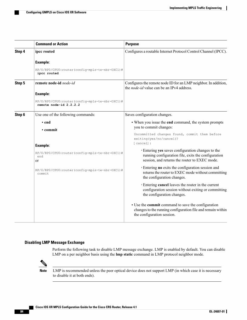
PurposeCommand or Action
Configures a routable Internet Protocol Control Channel (IPCC).ipcc routed
Example:
RP/0/RP0/CPU0:router(config-mpls-te-nbr-OXC1)#
Step 4
ipcc routed
Configures the remote node ID for an LMP neighbor. In addition,the node-id value can be an IPv4 address.
remote node-id node-id
Example:
RP/0/RP0/CPU0:router(config-mpls-te-nbr-OXC1)#
Step 5
remote node-id 2.2.2.2
Saves configuration changes.Use one of the following commands:Step 6
• end •When you issue the end command, the system promptsyou to commit changes:
Uncommitted changes found, commit them beforeexiting(yes/no/cancel)?[cancel]:
• commit
Example:
RP/0/RP0/CPU0:router(config-mpls-te-nbr-OXC1)#end
◦Entering yes saves configuration changes to therunning configuration file, exits the configurationsession, and returns the router to EXEC mode.or
RP/0/RP0/CPU0:router(config-mpls-te-nbr-OXC1)#commit
◦Entering no exits the configuration session andreturns the router to EXECmode without committingthe configuration changes.
◦Entering cancel leaves the router in the currentconfiguration session without exiting or committingthe configuration changes.
• Use the commit command to save the configurationchanges to the running configuration file and remain withinthe configuration session.
Disabling LMP Message Exchange
Perform the following task to disable LMP message exchange. LMP is enabled by default. You can disableLMP on a per neighbor basis using the lmp static command in LMP protocol neighbor mode.
LMP is recommended unless the peer optical device does not support LMP (in which case it is necessaryto disable it at both ends).
Note
Cisco IOS XR MPLS Configuration Guide for the Cisco CRS Router, Release 4.184 OL-24697-01
Implementing MPLS Traffic EngineeringConfiguring GMPLS on Cisco IOS XR Software
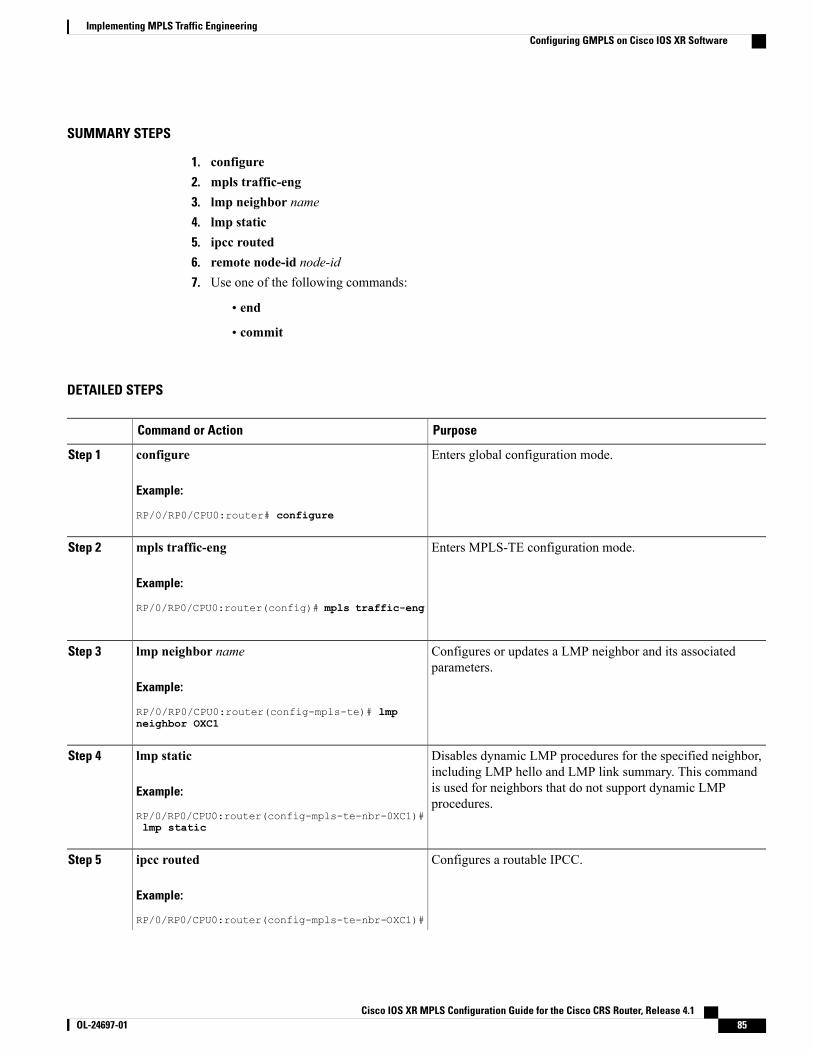
SUMMARY STEPS
1. configure2. mpls traffic-eng3. lmp neighbor name4. lmp static5. ipcc routed6. remote node-id node-id7. Use one of the following commands:
• end
• commit
DETAILED STEPS
PurposeCommand or Action
Enters global configuration mode.configure
Example:
RP/0/RP0/CPU0:router# configure
Step 1
Enters MPLS-TE configuration mode.mpls traffic-eng
Example:
RP/0/RP0/CPU0:router(config)# mpls traffic-eng
Step 2
Configures or updates a LMP neighbor and its associatedparameters.
lmp neighbor name
Example:
RP/0/RP0/CPU0:router(config-mpls-te)# lmp
Step 3
neighbor OXC1
Disables dynamic LMP procedures for the specified neighbor,including LMP hello and LMP link summary. This command
lmp static
Example:
RP/0/RP0/CPU0:router(config-mpls-te-nbr-0XC1)#
Step 4
is used for neighbors that do not support dynamic LMPprocedures.
lmp static
Configures a routable IPCC.ipcc routed
Example:
RP/0/RP0/CPU0:router(config-mpls-te-nbr-OXC1)#
Step 5
Cisco IOS XR MPLS Configuration Guide for the Cisco CRS Router, Release 4.1 OL-24697-01 85
Implementing MPLS Traffic EngineeringConfiguring GMPLS on Cisco IOS XR Software
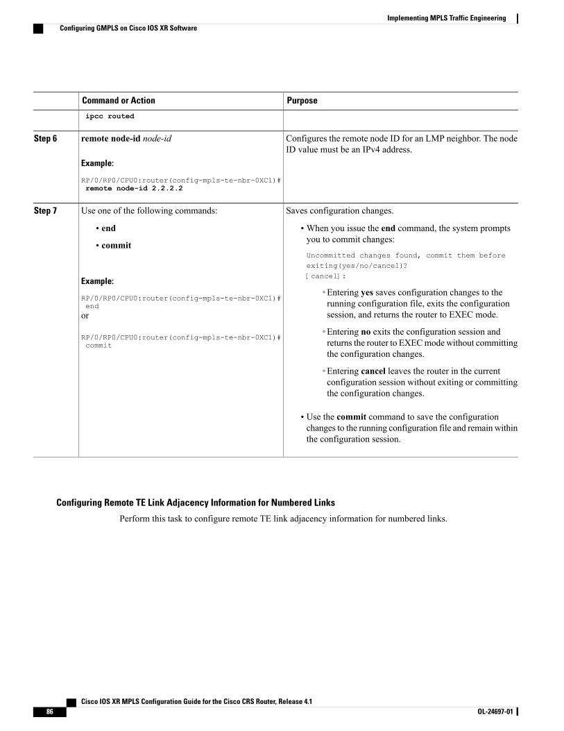
PurposeCommand or Action
ipcc routed
Configures the remote node ID for an LMP neighbor. The nodeID value must be an IPv4 address.
remote node-id node-id
Example:
RP/0/RP0/CPU0:router(config-mpls-te-nbr-0XC1)#
Step 6
remote node-id 2.2.2.2
Saves configuration changes.Use one of the following commands:Step 7
• end •When you issue the end command, the system promptsyou to commit changes:
Uncommitted changes found, commit them beforeexiting(yes/no/cancel)?[cancel]:
• commit
Example:
RP/0/RP0/CPU0:router(config-mpls-te-nbr-0XC1)#end
◦Entering yes saves configuration changes to therunning configuration file, exits the configurationsession, and returns the router to EXEC mode.or
RP/0/RP0/CPU0:router(config-mpls-te-nbr-0XC1)#commit
◦Entering no exits the configuration session andreturns the router to EXECmodewithout committingthe configuration changes.
◦Entering cancel leaves the router in the currentconfiguration session without exiting or committingthe configuration changes.
• Use the commit command to save the configurationchanges to the running configuration file and remain withinthe configuration session.
Configuring Remote TE Link Adjacency Information for Numbered Links
Perform this task to configure remote TE link adjacency information for numbered links.
Cisco IOS XR MPLS Configuration Guide for the Cisco CRS Router, Release 4.186 OL-24697-01
Implementing MPLS Traffic EngineeringConfiguring GMPLS on Cisco IOS XR Software
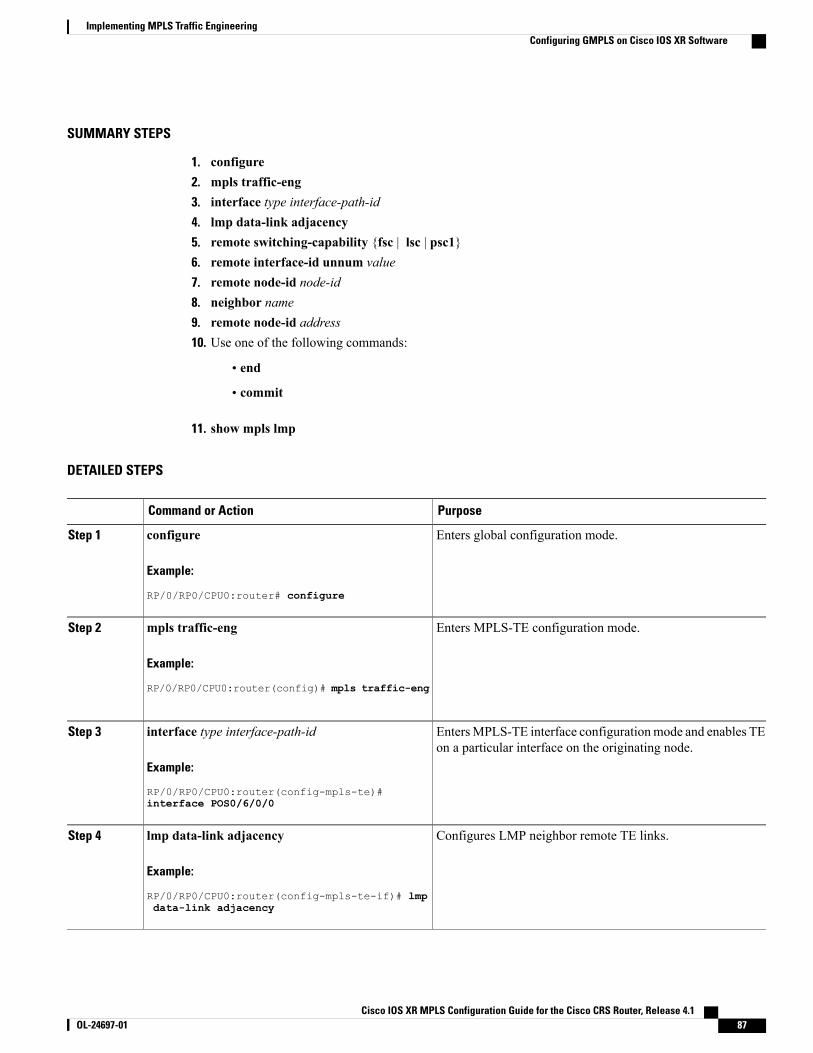
SUMMARY STEPS
1. configure2. mpls traffic-eng3. interface type interface-path-id4. lmp data-link adjacency5. remote switching-capability {fsc | lsc | psc1}6. remote interface-id unnum value7. remote node-id node-id8. neighbor name9. remote node-id address10. Use one of the following commands:
• end
• commit
11. show mpls lmp
DETAILED STEPS
PurposeCommand or Action
Enters global configuration mode.configure
Example:
RP/0/RP0/CPU0:router# configure
Step 1
Enters MPLS-TE configuration mode.mpls traffic-eng
Example:
RP/0/RP0/CPU0:router(config)# mpls traffic-eng
Step 2
EntersMPLS-TE interface configurationmode and enables TEon a particular interface on the originating node.
interface type interface-path-id
Example:
RP/0/RP0/CPU0:router(config-mpls-te)#
Step 3
interface POS0/6/0/0
Configures LMP neighbor remote TE links.lmp data-link adjacency
Example:
RP/0/RP0/CPU0:router(config-mpls-te-if)# lmp
Step 4
data-link adjacency
Cisco IOS XR MPLS Configuration Guide for the Cisco CRS Router, Release 4.1 OL-24697-01 87
Implementing MPLS Traffic EngineeringConfiguring GMPLS on Cisco IOS XR Software
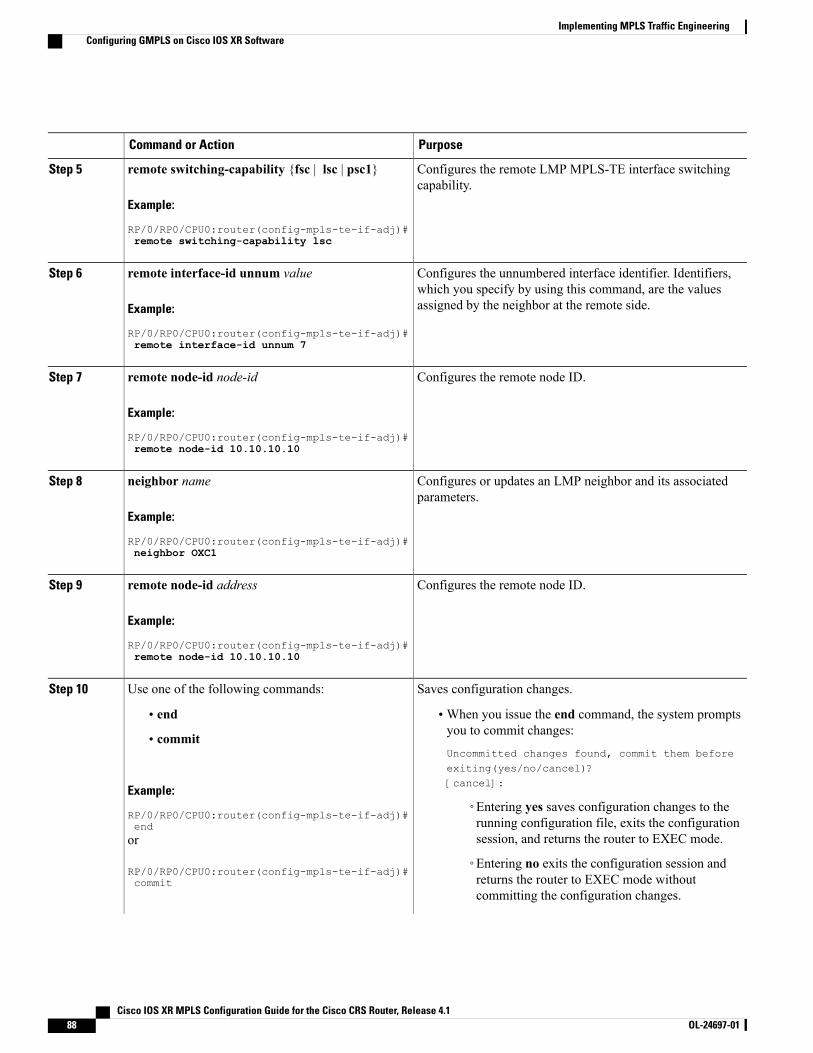
PurposeCommand or Action
Configures the remote LMP MPLS-TE interface switchingcapability.
remote switching-capability {fsc | lsc | psc1}
Example:
RP/0/RP0/CPU0:router(config-mpls-te-if-adj)#
Step 5
remote switching-capability lsc
Configures the unnumbered interface identifier. Identifiers,which you specify by using this command, are the valuesassigned by the neighbor at the remote side.
remote interface-id unnum value
Example:
RP/0/RP0/CPU0:router(config-mpls-te-if-adj)#
Step 6
remote interface-id unnum 7
Configures the remote node ID.remote node-id node-id
Example:
RP/0/RP0/CPU0:router(config-mpls-te-if-adj)#
Step 7
remote node-id 10.10.10.10
Configures or updates an LMP neighbor and its associatedparameters.
neighbor name
Example:
RP/0/RP0/CPU0:router(config-mpls-te-if-adj)#
Step 8
neighbor OXC1
Configures the remote node ID.remote node-id address
Example:
RP/0/RP0/CPU0:router(config-mpls-te-if-adj)#
Step 9
remote node-id 10.10.10.10
Saves configuration changes.Use one of the following commands:Step 10
• end •When you issue the end command, the system promptsyou to commit changes:
Uncommitted changes found, commit them beforeexiting(yes/no/cancel)?[cancel]:
• commit
Example:
RP/0/RP0/CPU0:router(config-mpls-te-if-adj)#end
◦Entering yes saves configuration changes to therunning configuration file, exits the configurationsession, and returns the router to EXEC mode.or
RP/0/RP0/CPU0:router(config-mpls-te-if-adj)#commit
◦Entering no exits the configuration session andreturns the router to EXEC mode withoutcommitting the configuration changes.
Cisco IOS XR MPLS Configuration Guide for the Cisco CRS Router, Release 4.188 OL-24697-01
Implementing MPLS Traffic EngineeringConfiguring GMPLS on Cisco IOS XR Software
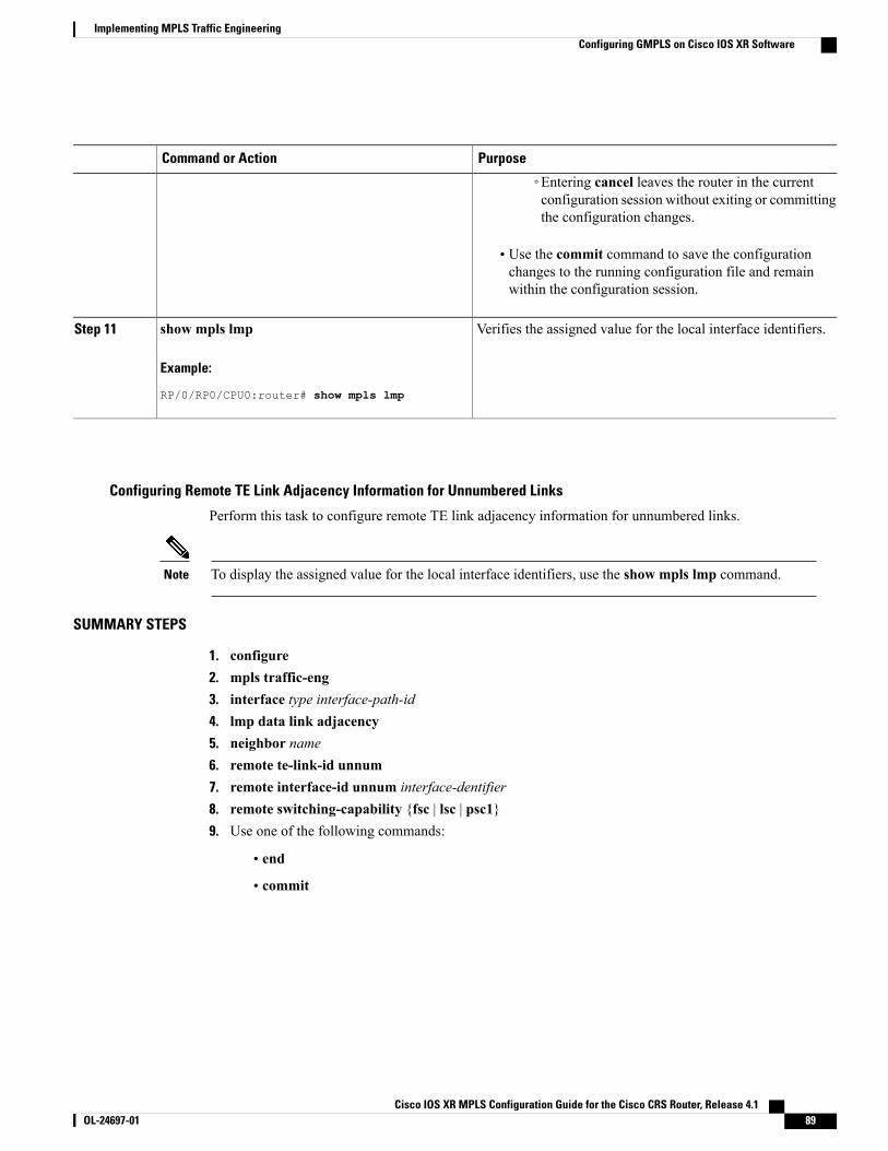
PurposeCommand or Action
◦Entering cancel leaves the router in the currentconfiguration session without exiting or committingthe configuration changes.
• Use the commit command to save the configurationchanges to the running configuration file and remainwithin the configuration session.
Verifies the assigned value for the local interface identifiers.show mpls lmp
Example:
RP/0/RP0/CPU0:router# show mpls lmp
Step 11
Configuring Remote TE Link Adjacency Information for Unnumbered Links
Perform this task to configure remote TE link adjacency information for unnumbered links.
To display the assigned value for the local interface identifiers, use the show mpls lmp command.Note
SUMMARY STEPS
1. configure2. mpls traffic-eng3. interface type interface-path-id4. lmp data link adjacency5. neighbor name6. remote te-link-id unnum7. remote interface-id unnum interface-dentifier8. remote switching-capability {fsc | lsc | psc1}9. Use one of the following commands:
• end
• commit
Cisco IOS XR MPLS Configuration Guide for the Cisco CRS Router, Release 4.1 OL-24697-01 89
Implementing MPLS Traffic EngineeringConfiguring GMPLS on Cisco IOS XR Software
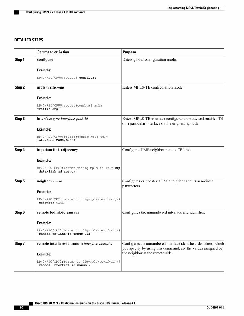
DETAILED STEPS
PurposeCommand or Action
Enters global configuration mode.configure
Example:
RP/0/RP0/CPU0:router# configure
Step 1
Enters MPLS-TE configuration mode.mpls traffic-eng
Example:
RP/0/RP0/CPU0:router(config)# mpls
Step 2
traffic-eng
Enters MPLS-TE interface configuration mode and enables TEon a particular interface on the originating node.
interface type interface-path-id
Example:
RP/0/RP0/CPU0:router(config-mpls-te)#
Step 3
interface POS0/6/0/0
Configures LMP neighbor remote TE links.lmp data link adjacency
Example:
RP/0/RP0/CPU0:router(config-mpls-te-if)# lmp
Step 4
data-link adjacency
Configures or updates a LMP neighbor and its associatedparameters.
neighbor name
Example:
RP/0/RP0/CPU0:router(config-mpls-te-if-adj)#
Step 5
neighbor OXC1
Configures the unnumbered interface and identifier.remote te-link-id unnum
Example:
RP/0/RP0/CPU0:router(config-mpls-te-if-adj)#
Step 6
remote te-link-id unnum 111
Configures the unnumbered interface identifier. Identifiers, whichyou specify by using this command, are the values assigned bythe neighbor at the remote side.
remote interface-id unnum interface-dentifier
Example:
RP/0/RP0/CPU0:router(config-mpls-te-if-adj)#
Step 7
remote interface-id unnum 7
Cisco IOS XR MPLS Configuration Guide for the Cisco CRS Router, Release 4.190 OL-24697-01
Implementing MPLS Traffic EngineeringConfiguring GMPLS on Cisco IOS XR Software
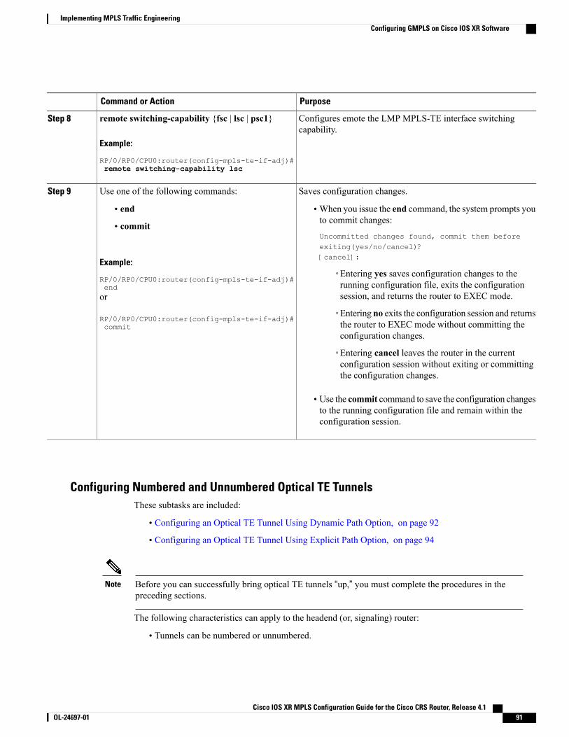
PurposeCommand or Action
Configures emote the LMP MPLS-TE interface switchingcapability.
remote switching-capability {fsc | lsc | psc1}
Example:
RP/0/RP0/CPU0:router(config-mpls-te-if-adj)#
Step 8
remote switching-capability lsc
Saves configuration changes.Use one of the following commands:Step 9
• end •When you issue the end command, the system prompts youto commit changes:
Uncommitted changes found, commit them beforeexiting(yes/no/cancel)?[cancel]:
• commit
Example:
RP/0/RP0/CPU0:router(config-mpls-te-if-adj)#end
◦Entering yes saves configuration changes to therunning configuration file, exits the configurationsession, and returns the router to EXEC mode.or
RP/0/RP0/CPU0:router(config-mpls-te-if-adj)#commit
◦Entering no exits the configuration session and returnsthe router to EXEC mode without committing theconfiguration changes.
◦Entering cancel leaves the router in the currentconfiguration session without exiting or committingthe configuration changes.
• Use the commit command to save the configuration changesto the running configuration file and remain within theconfiguration session.
Configuring Numbered and Unnumbered Optical TE TunnelsThese subtasks are included:
• Configuring an Optical TE Tunnel Using Dynamic Path Option, on page 92
• Configuring an Optical TE Tunnel Using Explicit Path Option, on page 94
Before you can successfully bring optical TE tunnels “up,” you must complete the procedures in thepreceding sections.
Note
The following characteristics can apply to the headend (or, signaling) router:
• Tunnels can be numbered or unnumbered.
Cisco IOS XR MPLS Configuration Guide for the Cisco CRS Router, Release 4.1 OL-24697-01 91
Implementing MPLS Traffic EngineeringConfiguring GMPLS on Cisco IOS XR Software
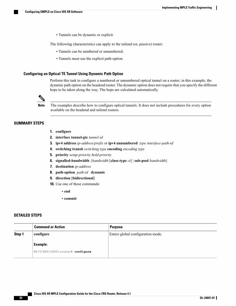
• Tunnels can be dynamic or explicit.
The following characteristics can apply to the tailend (or, passive) router:
• Tunnels can be numbered or unnumbered.
• Tunnels must use the explicit path-option.
Configuring an Optical TE Tunnel Using Dynamic Path Option
Perform this task to configure a numbered or unnumbered optical tunnel on a router; in this example, thedynamic path option on the headend router. The dynamic option does not require that you specify the differenthops to be taken along the way. The hops are calculated automatically.
The examples describe how to configure optical tunnels. It does not include procedures for every optionavailable on the headend and tailend routers.
Note
SUMMARY STEPS
1. configure2. interface tunnel-gte tunnel-id3. ipv4 address ip-address/prefix or ipv4 unnumbered type interface-path-id4. switching transit switching type encoding encoding type5. priority setup-priority hold-priority6. signalled-bandwidth {bandwidth [class-type ct] | sub-pool bandwidth}7. destination ip-address8. path-option path-id dynamic9. direction [bidirectional]10. Use one of these commands:
• end
• commit
DETAILED STEPS
PurposeCommand or Action
Enters global configuration mode.configure
Example:
RP/0/RP0/CPU0:router# configure
Step 1
Cisco IOS XR MPLS Configuration Guide for the Cisco CRS Router, Release 4.192 OL-24697-01
Implementing MPLS Traffic EngineeringConfiguring GMPLS on Cisco IOS XR Software
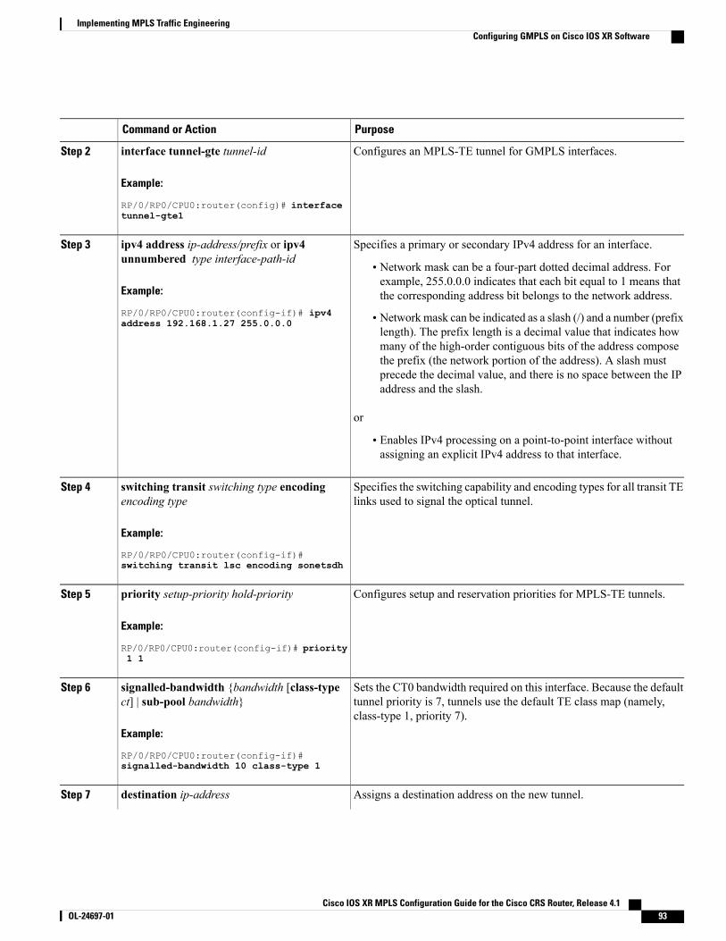
PurposeCommand or Action
Configures an MPLS-TE tunnel for GMPLS interfaces.interface tunnel-gte tunnel-id
Example:
RP/0/RP0/CPU0:router(config)# interface
Step 2
tunnel-gte1
Specifies a primary or secondary IPv4 address for an interface.ipv4 address ip-address/prefix or ipv4unnumbered type interface-path-id
Step 3
• Network mask can be a four-part dotted decimal address. Forexample, 255.0.0.0 indicates that each bit equal to 1 means thatthe corresponding address bit belongs to the network address.Example:
RP/0/RP0/CPU0:router(config-if)# ipv4 • Network mask can be indicated as a slash (/) and a number (prefixlength). The prefix length is a decimal value that indicates how
address 192.168.1.27 255.0.0.0
many of the high-order contiguous bits of the address composethe prefix (the network portion of the address). A slash mustprecede the decimal value, and there is no space between the IPaddress and the slash.
or
• Enables IPv4 processing on a point-to-point interface withoutassigning an explicit IPv4 address to that interface.
Specifies the switching capability and encoding types for all transit TElinks used to signal the optical tunnel.
switching transit switching type encodingencoding type
Example:
RP/0/RP0/CPU0:router(config-if)#
Step 4
switching transit lsc encoding sonetsdh
Configures setup and reservation priorities for MPLS-TE tunnels.priority setup-priority hold-priority
Example:
RP/0/RP0/CPU0:router(config-if)# priority
Step 5
1 1
Sets the CT0 bandwidth required on this interface. Because the defaulttunnel priority is 7, tunnels use the default TE class map (namely,class-type 1, priority 7).
signalled-bandwidth {bandwidth [class-typect] | sub-pool bandwidth}
Example:
RP/0/RP0/CPU0:router(config-if)#
Step 6
signalled-bandwidth 10 class-type 1
Assigns a destination address on the new tunnel.destination ip-addressStep 7
Cisco IOS XR MPLS Configuration Guide for the Cisco CRS Router, Release 4.1 OL-24697-01 93
Implementing MPLS Traffic EngineeringConfiguring GMPLS on Cisco IOS XR Software
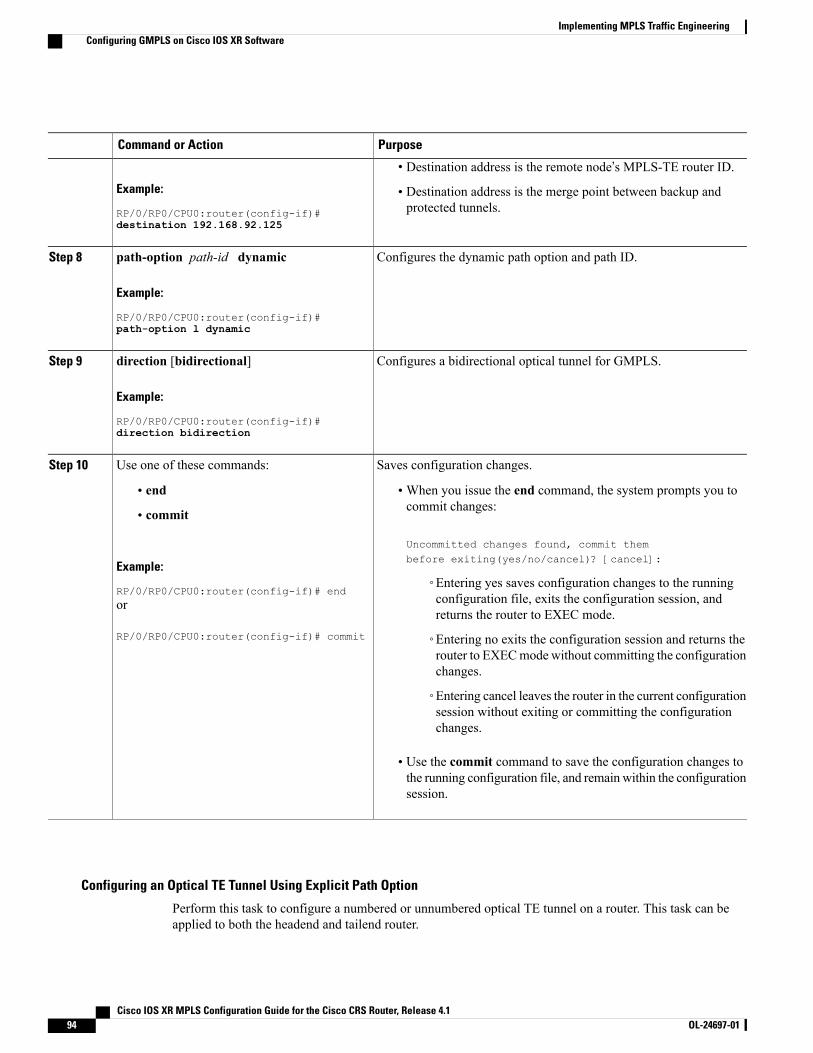
PurposeCommand or Action
Example:
RP/0/RP0/CPU0:router(config-if)#
• Destination address is the remote node’s MPLS-TE router ID.
• Destination address is the merge point between backup andprotected tunnels.
destination 192.168.92.125
Configures the dynamic path option and path ID.path-option path-id dynamic
Example:
RP/0/RP0/CPU0:router(config-if)#
Step 8
path-option l dynamic
Configures a bidirectional optical tunnel for GMPLS.direction [bidirectional]
Example:
RP/0/RP0/CPU0:router(config-if)#
Step 9
direction bidirection
Saves configuration changes.Use one of these commands:Step 10
• end •When you issue the end command, the system prompts you tocommit changes:
Uncommitted changes found, commit thembefore exiting(yes/no/cancel)? [cancel]:
• commit
Example:
RP/0/RP0/CPU0:router(config-if)# end◦Entering yes saves configuration changes to the runningconfiguration file, exits the configuration session, andreturns the router to EXEC mode.
or
RP/0/RP0/CPU0:router(config-if)# commit ◦Entering no exits the configuration session and returns therouter to EXECmode without committing the configurationchanges.
◦Entering cancel leaves the router in the current configurationsession without exiting or committing the configurationchanges.
• Use the commit command to save the configuration changes tothe running configuration file, and remain within the configurationsession.
Configuring an Optical TE Tunnel Using Explicit Path Option
Perform this task to configure a numbered or unnumbered optical TE tunnel on a router. This task can beapplied to both the headend and tailend router.
Cisco IOS XR MPLS Configuration Guide for the Cisco CRS Router, Release 4.194 OL-24697-01
Implementing MPLS Traffic EngineeringConfiguring GMPLS on Cisco IOS XR Software
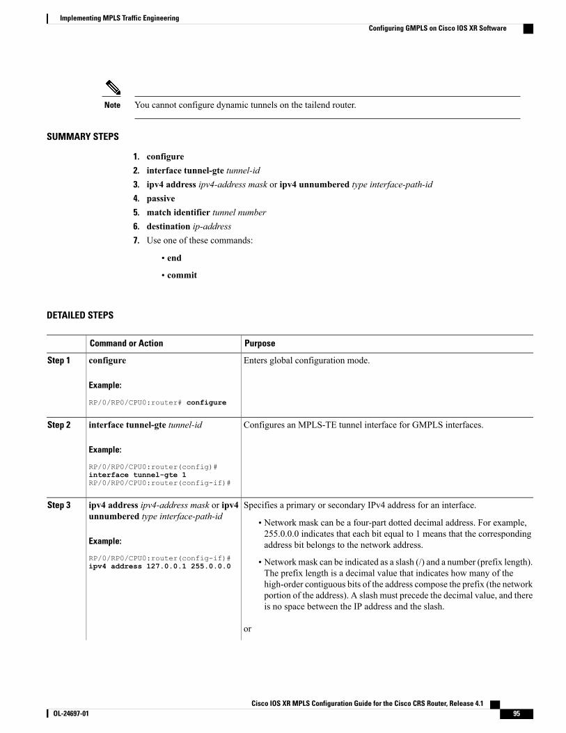
You cannot configure dynamic tunnels on the tailend router.Note
SUMMARY STEPS
1. configure2. interface tunnel-gte tunnel-id3. ipv4 address ipv4-address mask or ipv4 unnumbered type interface-path-id4. passive5. match identifier tunnel number6. destination ip-address7. Use one of these commands:
• end
• commit
DETAILED STEPS
PurposeCommand or Action
Enters global configuration mode.configure
Example:
RP/0/RP0/CPU0:router# configure
Step 1
Configures an MPLS-TE tunnel interface for GMPLS interfaces.interface tunnel-gte tunnel-id
Example:
RP/0/RP0/CPU0:router(config)#
Step 2
interface tunnel-gte 1RP/0/RP0/CPU0:router(config-if)#
Specifies a primary or secondary IPv4 address for an interface.ipv4 address ipv4-address mask or ipv4unnumbered type interface-path-id
Step 3
• Network mask can be a four-part dotted decimal address. For example,255.0.0.0 indicates that each bit equal to 1 means that the correspondingaddress bit belongs to the network address.Example:
RP/0/RP0/CPU0:router(config-if)# • Network mask can be indicated as a slash (/) and a number (prefix length).The prefix length is a decimal value that indicates how many of the
ipv4 address 127.0.0.1 255.0.0.0
high-order contiguous bits of the address compose the prefix (the networkportion of the address). A slash must precede the decimal value, and thereis no space between the IP address and the slash.
or
Cisco IOS XR MPLS Configuration Guide for the Cisco CRS Router, Release 4.1 OL-24697-01 95
Implementing MPLS Traffic EngineeringConfiguring GMPLS on Cisco IOS XR Software
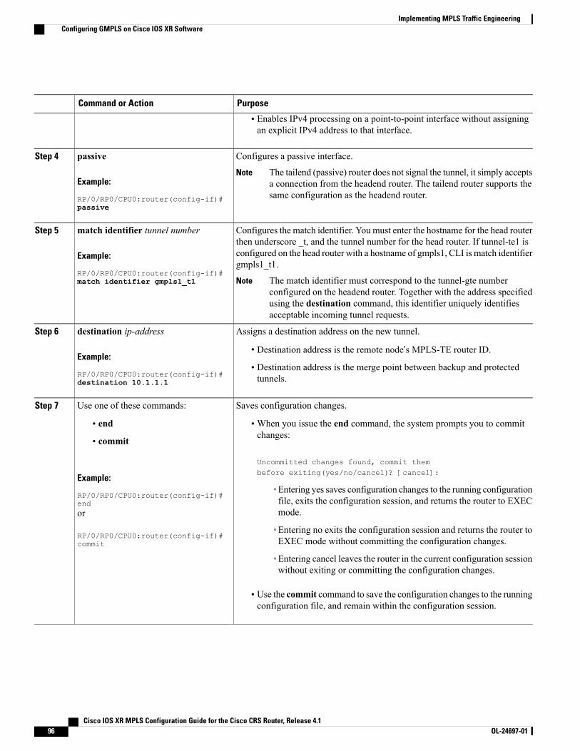
PurposeCommand or Action
• Enables IPv4 processing on a point-to-point interface without assigningan explicit IPv4 address to that interface.
Configures a passive interface.passiveStep 4
Example:
RP/0/RP0/CPU0:router(config-if)#
The tailend (passive) router does not signal the tunnel, it simply acceptsa connection from the headend router. The tailend router supports thesame configuration as the headend router.
Note
passive
Configures the match identifier. Youmust enter the hostname for the head routerthen underscore _t, and the tunnel number for the head router. If tunnel-te1 is
match identifier tunnel number
Example:
RP/0/RP0/CPU0:router(config-if)#
Step 5
configured on the head router with a hostname of gmpls1, CLI is match identifiergmpls1_t1.
The match identifier must correspond to the tunnel-gte numberconfigured on the headend router. Together with the address specifiedusing the destination command, this identifier uniquely identifiesacceptable incoming tunnel requests.
Notematch identifier gmpls1_t1
Assigns a destination address on the new tunnel.destination ip-addressStep 6
Example:
RP/0/RP0/CPU0:router(config-if)#
• Destination address is the remote node’s MPLS-TE router ID.
• Destination address is the merge point between backup and protectedtunnels.destination 10.1.1.1
Saves configuration changes.Use one of these commands:Step 7
• end •When you issue the end command, the system prompts you to commitchanges:
Uncommitted changes found, commit thembefore exiting(yes/no/cancel)? [cancel]:
• commit
Example:
RP/0/RP0/CPU0:router(config-if)#end
◦Entering yes saves configuration changes to the running configurationfile, exits the configuration session, and returns the router to EXECmode.or
RP/0/RP0/CPU0:router(config-if)#commit
◦Entering no exits the configuration session and returns the router toEXEC mode without committing the configuration changes.
◦Entering cancel leaves the router in the current configuration sessionwithout exiting or committing the configuration changes.
• Use the commit command to save the configuration changes to the runningconfiguration file, and remain within the configuration session.
Cisco IOS XR MPLS Configuration Guide for the Cisco CRS Router, Release 4.196 OL-24697-01
Implementing MPLS Traffic EngineeringConfiguring GMPLS on Cisco IOS XR Software
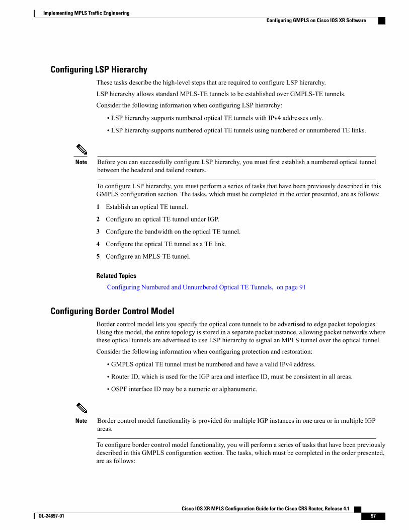
Configuring LSP HierarchyThese tasks describe the high-level steps that are required to configure LSP hierarchy.
LSP hierarchy allows standard MPLS-TE tunnels to be established over GMPLS-TE tunnels.
Consider the following information when configuring LSP hierarchy:
• LSP hierarchy supports numbered optical TE tunnels with IPv4 addresses only.
• LSP hierarchy supports numbered optical TE tunnels using numbered or unnumbered TE links.
Before you can successfully configure LSP hierarchy, you must first establish a numbered optical tunnelbetween the headend and tailend routers.
Note
To configure LSP hierarchy, you must perform a series of tasks that have been previously described in thisGMPLS configuration section. The tasks, which must be completed in the order presented, are as follows:
1 Establish an optical TE tunnel.
2 Configure an optical TE tunnel under IGP.
3 Configure the bandwidth on the optical TE tunnel.
4 Configure the optical TE tunnel as a TE link.
5 Configure an MPLS-TE tunnel.
Related Topics
Configuring Numbered and Unnumbered Optical TE Tunnels, on page 91
Configuring Border Control ModelBorder control model lets you specify the optical core tunnels to be advertised to edge packet topologies.Using this model, the entire topology is stored in a separate packet instance, allowing packet networks wherethese optical tunnels are advertised to use LSP hierarchy to signal an MPLS tunnel over the optical tunnel.
Consider the following information when configuring protection and restoration:
• GMPLS optical TE tunnel must be numbered and have a valid IPv4 address.
• Router ID, which is used for the IGP area and interface ID, must be consistent in all areas.
• OSPF interface ID may be a numeric or alphanumeric.
Border control model functionality is provided for multiple IGP instances in one area or in multiple IGPareas.
Note
To configure border control model functionality, you will perform a series of tasks that have been previouslydescribed in this GMPLS configuration section. The tasks, which must be completed in the order presented,are as follows:
Cisco IOS XR MPLS Configuration Guide for the Cisco CRS Router, Release 4.1 OL-24697-01 97
Implementing MPLS Traffic EngineeringConfiguring GMPLS on Cisco IOS XR Software
1 Configure two optical tunnels on different interfaces.
When configuring IGP, you must keep the optical and packet topology information in separate routingtables.
Note
2 Configure OSPF adjacency on each tunnel.
3 Configure bandwidth on each tunnel.
4 Configure packet tunnels.
Configuring Path ProtectionThese tasks describe how to configure path protection:
• Configuring an LSP, on page 98
• Forcing Reversion of the LSP, on page 101
Configuring an LSP
Perform this task to configure an LSP for an explicit path. Path protection is enabled on a tunnel by addingan additional path option configuration at the active end. The path can be configured either explicitly ordynamically.
When the dynamic option is used for both working and protecting LSPs, CSPF extensions are used todetermine paths with different degrees of diversity. When the paths are computed, they are used over thelifetime of the LSPs. The nodes on the path of the LSP determine if the PSR is or is not for a given LSP.This determination is based on information that is obtained at signaling.
Note
Cisco IOS XR MPLS Configuration Guide for the Cisco CRS Router, Release 4.198 OL-24697-01
Implementing MPLS Traffic EngineeringConfiguring GMPLS on Cisco IOS XR Software
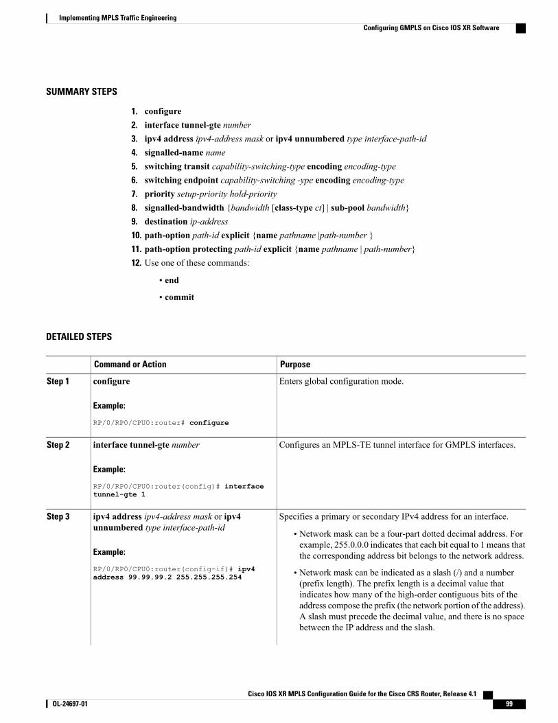
SUMMARY STEPS
1. configure2. interface tunnel-gte number3. ipv4 address ipv4-address mask or ipv4 unnumbered type interface-path-id4. signalled-name name5. switching transit capability-switching-type encoding encoding-type6. switching endpoint capability-switching -ype encoding encoding-type7. priority setup-priority hold-priority8. signalled-bandwidth {bandwidth [class-type ct] | sub-pool bandwidth}9. destination ip-address10. path-option path-id explicit {name pathname |path-number }11. path-option protecting path-id explicit {name pathname | path-number}12. Use one of these commands:
• end
• commit
DETAILED STEPS
PurposeCommand or Action
Enters global configuration mode.configure
Example:
RP/0/RP0/CPU0:router# configure
Step 1
Configures an MPLS-TE tunnel interface for GMPLS interfaces.interface tunnel-gte number
Example:
RP/0/RP0/CPU0:router(config)# interface
Step 2
tunnel-gte 1
Specifies a primary or secondary IPv4 address for an interface.ipv4 address ipv4-address mask or ipv4unnumbered type interface-path-id
Step 3
• Network mask can be a four-part dotted decimal address. Forexample, 255.0.0.0 indicates that each bit equal to 1 means thatthe corresponding address bit belongs to the network address.Example:
RP/0/RP0/CPU0:router(config-if)# ipv4 • Network mask can be indicated as a slash (/) and a number(prefix length). The prefix length is a decimal value that
address 99.99.99.2 255.255.255.254
indicates how many of the high-order contiguous bits of theaddress compose the prefix (the network portion of the address).A slash must precede the decimal value, and there is no spacebetween the IP address and the slash.
Cisco IOS XR MPLS Configuration Guide for the Cisco CRS Router, Release 4.1 OL-24697-01 99
Implementing MPLS Traffic EngineeringConfiguring GMPLS on Cisco IOS XR Software
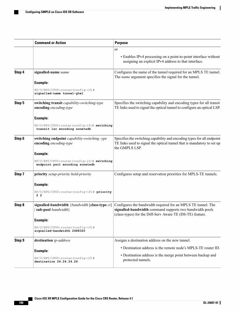
PurposeCommand or Action
or
• Enables IPv4 processing on a point-to-point interface withoutassigning an explicit IPv4 address to that interface.
Configures the name of the tunnel required for an MPLS TE tunnel.The name argument specifies the signal for the tunnel.
signalled-name name
Example:
RP/0/RP0/CPU0:router(config-if)#
Step 4
signalled-name tunnel-gte1
Specifies the switching capability and encoding types for all transitTE links used to signal the optical tunnel to configure an optical LSP.
switching transit capability-switching-typeencoding encoding-type
Example:
RP/0/RP0/CPU0:router(config-if)# switching
Step 5
transit lsc encoding sonetsdh
Specifies the switching capability and encoding types for all endpointTE links used to signal the optical tunnel that is mandatory to set upthe GMPLS LSP.
switching endpoint capability-switching -ypeencoding encoding-type
Example:
RP/0/RP0/CPU0:router(config-if)# switching
Step 6
endpoint psc1 encoding sonetsdh
Configures setup and reservation priorities for MPLS-TE tunnels.priority setup-priority hold-priority
Example:
RP/0/RP0/CPU0:router(config-if)# priority
Step 7
2 2
Configures the bandwidth required for an MPLS TE tunnel. Thesignalled-bandwidth command supports two bandwidth pools(class-types) for the Diff-Serv Aware TE (DS-TE) feature.
signalled-bandwidth {bandwidth [class-type ct]| sub-pool bandwidth}
Example:
RP/0/RP0/CPU0:router(config-if)#
Step 8
signalled-bandwidth 2488320
Assigns a destination address on the new tunnel.destination ip-addressStep 9
Example:
RP/0/RP0/CPU0:router(config-if)#
• Destination address is the remote node’s MPLS-TE router ID.
• Destination address is the merge point between backup andprotected tunnels.destination 24.24.24.24
Cisco IOS XR MPLS Configuration Guide for the Cisco CRS Router, Release 4.1100 OL-24697-01
Implementing MPLS Traffic EngineeringConfiguring GMPLS on Cisco IOS XR Software
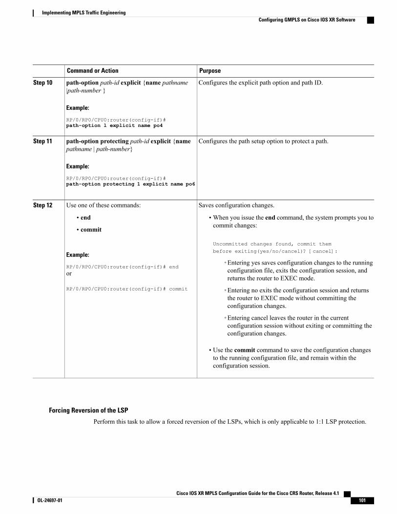
PurposeCommand or Action
Configures the explicit path option and path ID.path-option path-id explicit {name pathname|path-number }
Step 10
Example:
RP/0/RP0/CPU0:router(config-if)#path-option l explicit name po4
Configures the path setup option to protect a path.path-option protecting path-id explicit {namepathname | path-number}
Step 11
Example:
RP/0/RP0/CPU0:router(config-if)#path-option protecting 1 explicit name po6
Saves configuration changes.Use one of these commands:Step 12
• end •When you issue the end command, the system prompts you tocommit changes:
Uncommitted changes found, commit thembefore exiting(yes/no/cancel)? [cancel]:
• commit
Example:
RP/0/RP0/CPU0:router(config-if)# end◦Entering yes saves configuration changes to the runningconfiguration file, exits the configuration session, andreturns the router to EXEC mode.
or
RP/0/RP0/CPU0:router(config-if)# commit ◦Entering no exits the configuration session and returnsthe router to EXEC mode without committing theconfiguration changes.
◦Entering cancel leaves the router in the currentconfiguration session without exiting or committing theconfiguration changes.
• Use the commit command to save the configuration changesto the running configuration file, and remain within theconfiguration session.
Forcing Reversion of the LSP
Perform this task to allow a forced reversion of the LSPs, which is only applicable to 1:1 LSP protection.
Cisco IOS XR MPLS Configuration Guide for the Cisco CRS Router, Release 4.1 OL-24697-01 101
Implementing MPLS Traffic EngineeringConfiguring GMPLS on Cisco IOS XR Software
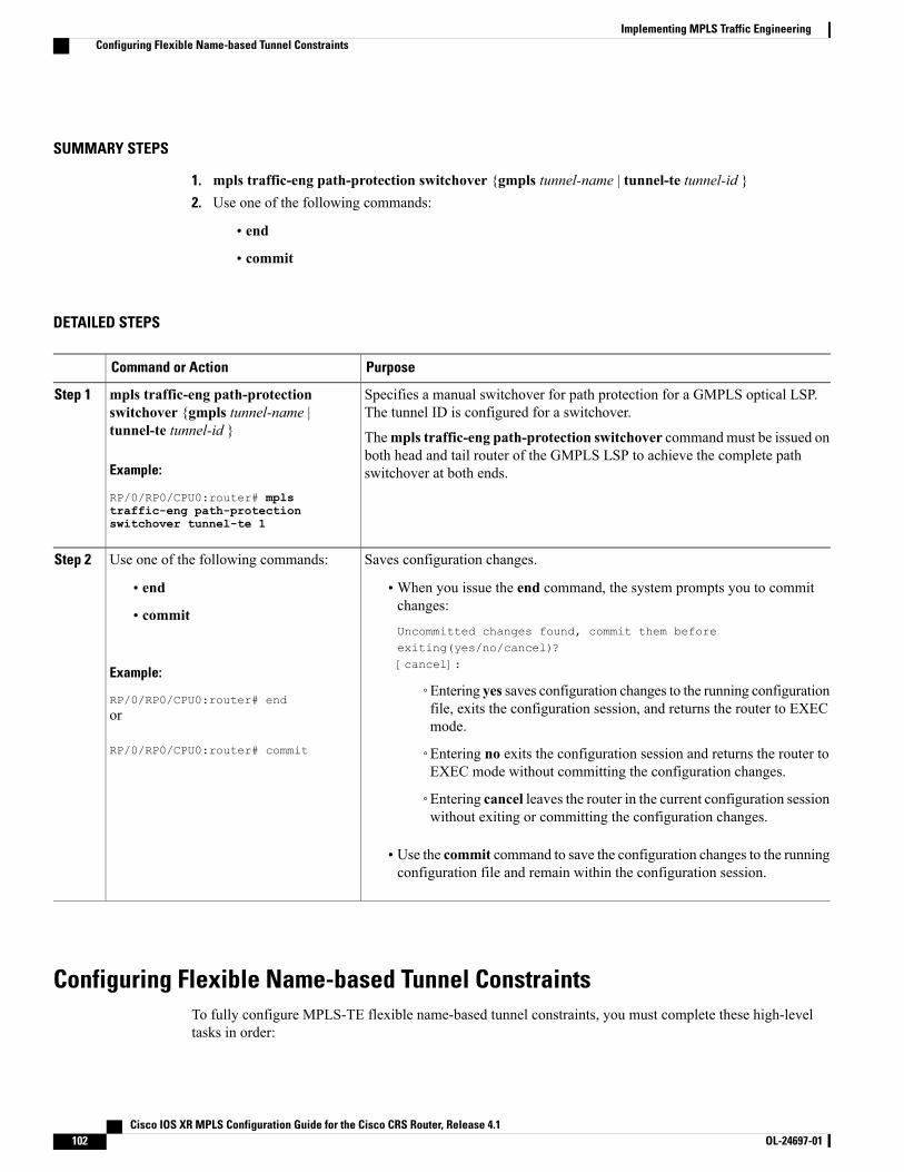
SUMMARY STEPS
1. mpls traffic-eng path-protection switchover {gmpls tunnel-name | tunnel-te tunnel-id }2. Use one of the following commands:
• end
• commit
DETAILED STEPS
PurposeCommand or Action
Specifies a manual switchover for path protection for a GMPLS optical LSP.The tunnel ID is configured for a switchover.
mpls traffic-eng path-protectionswitchover {gmpls tunnel-name |tunnel-te tunnel-id }
Step 1
Thempls traffic-eng path-protection switchover commandmust be issued onboth head and tail router of the GMPLS LSP to achieve the complete pathswitchover at both ends.Example:
RP/0/RP0/CPU0:router# mplstraffic-eng path-protectionswitchover tunnel-te 1
Saves configuration changes.Use one of the following commands:Step 2
• end •When you issue the end command, the system prompts you to commitchanges:
Uncommitted changes found, commit them beforeexiting(yes/no/cancel)?[cancel]:
• commit
Example:
RP/0/RP0/CPU0:router# end◦Entering yes saves configuration changes to the running configurationfile, exits the configuration session, and returns the router to EXECmode.
or
RP/0/RP0/CPU0:router# commit ◦Entering no exits the configuration session and returns the router toEXEC mode without committing the configuration changes.
◦Entering cancel leaves the router in the current configuration sessionwithout exiting or committing the configuration changes.
• Use the commit command to save the configuration changes to the runningconfiguration file and remain within the configuration session.
Configuring Flexible Name-based Tunnel ConstraintsTo fully configure MPLS-TE flexible name-based tunnel constraints, you must complete these high-leveltasks in order:
Cisco IOS XR MPLS Configuration Guide for the Cisco CRS Router, Release 4.1102 OL-24697-01
Implementing MPLS Traffic EngineeringConfiguring Flexible Name-based Tunnel Constraints
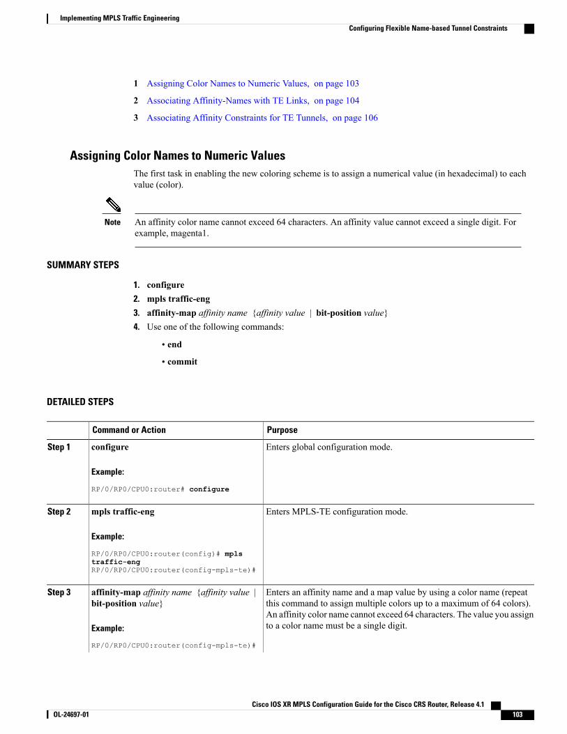
1 Assigning Color Names to Numeric Values, on page 103
2 Associating Affinity-Names with TE Links, on page 104
3 Associating Affinity Constraints for TE Tunnels, on page 106
Assigning Color Names to Numeric ValuesThe first task in enabling the new coloring scheme is to assign a numerical value (in hexadecimal) to eachvalue (color).
An affinity color name cannot exceed 64 characters. An affinity value cannot exceed a single digit. Forexample, magenta1.
Note
SUMMARY STEPS
1. configure2. mpls traffic-eng3. affinity-map affinity name {affinity value | bit-position value}4. Use one of the following commands:
• end
• commit
DETAILED STEPS
PurposeCommand or Action
Enters global configuration mode.configure
Example:
RP/0/RP0/CPU0:router# configure
Step 1
Enters MPLS-TE configuration mode.mpls traffic-eng
Example:
RP/0/RP0/CPU0:router(config)# mpls
Step 2
traffic-engRP/0/RP0/CPU0:router(config-mpls-te)#
Enters an affinity name and a map value by using a color name (repeatthis command to assign multiple colors up to a maximum of 64 colors).
affinity-map affinity name {affinity value |bit-position value}
Step 3
An affinity color name cannot exceed 64 characters. The value you assignto a color name must be a single digit.Example:
RP/0/RP0/CPU0:router(config-mpls-te)#
Cisco IOS XR MPLS Configuration Guide for the Cisco CRS Router, Release 4.1 OL-24697-01 103
Implementing MPLS Traffic EngineeringConfiguring Flexible Name-based Tunnel Constraints
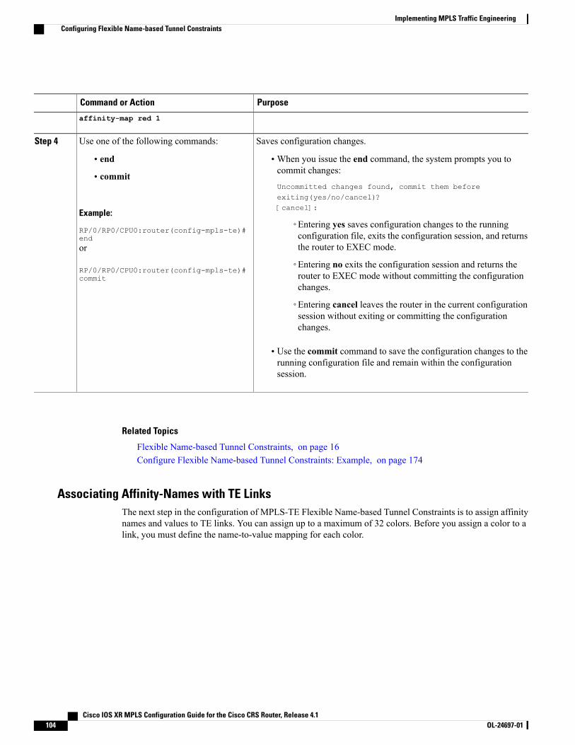
PurposeCommand or Action
affinity-map red 1
Saves configuration changes.Use one of the following commands:Step 4
• end •When you issue the end command, the system prompts you tocommit changes:
Uncommitted changes found, commit them beforeexiting(yes/no/cancel)?[cancel]:
• commit
Example:
RP/0/RP0/CPU0:router(config-mpls-te)#end
◦Entering yes saves configuration changes to the runningconfiguration file, exits the configuration session, and returnsthe router to EXEC mode.or
RP/0/RP0/CPU0:router(config-mpls-te)#commit
◦Entering no exits the configuration session and returns therouter to EXEC mode without committing the configurationchanges.
◦Entering cancel leaves the router in the current configurationsession without exiting or committing the configurationchanges.
• Use the commit command to save the configuration changes to therunning configuration file and remain within the configurationsession.
Related Topics
Flexible Name-based Tunnel Constraints, on page 16Configure Flexible Name-based Tunnel Constraints: Example, on page 174
Associating Affinity-Names with TE LinksThe next step in the configuration of MPLS-TE Flexible Name-based Tunnel Constraints is to assign affinitynames and values to TE links. You can assign up to a maximum of 32 colors. Before you assign a color to alink, you must define the name-to-value mapping for each color.
Cisco IOS XR MPLS Configuration Guide for the Cisco CRS Router, Release 4.1104 OL-24697-01
Implementing MPLS Traffic EngineeringConfiguring Flexible Name-based Tunnel Constraints
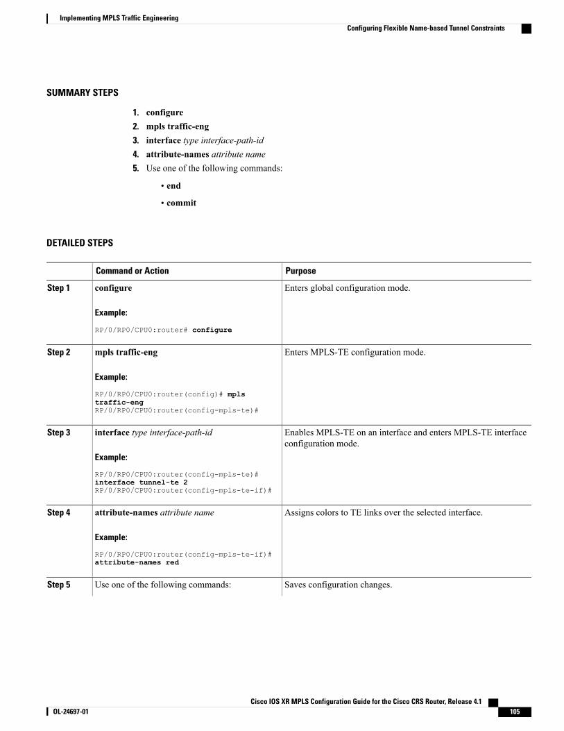
SUMMARY STEPS
1. configure2. mpls traffic-eng3. interface type interface-path-id4. attribute-names attribute name5. Use one of the following commands:
• end
• commit
DETAILED STEPS
PurposeCommand or Action
Enters global configuration mode.configure
Example:
RP/0/RP0/CPU0:router# configure
Step 1
Enters MPLS-TE configuration mode.mpls traffic-eng
Example:
RP/0/RP0/CPU0:router(config)# mpls
Step 2
traffic-engRP/0/RP0/CPU0:router(config-mpls-te)#
Enables MPLS-TE on an interface and enters MPLS-TE interfaceconfiguration mode.
interface type interface-path-id
Example:
RP/0/RP0/CPU0:router(config-mpls-te)#
Step 3
interface tunnel-te 2RP/0/RP0/CPU0:router(config-mpls-te-if)#
Assigns colors to TE links over the selected interface.attribute-names attribute name
Example:
RP/0/RP0/CPU0:router(config-mpls-te-if)#
Step 4
attribute-names red
Saves configuration changes.Use one of the following commands:Step 5
Cisco IOS XR MPLS Configuration Guide for the Cisco CRS Router, Release 4.1 OL-24697-01 105
Implementing MPLS Traffic EngineeringConfiguring Flexible Name-based Tunnel Constraints
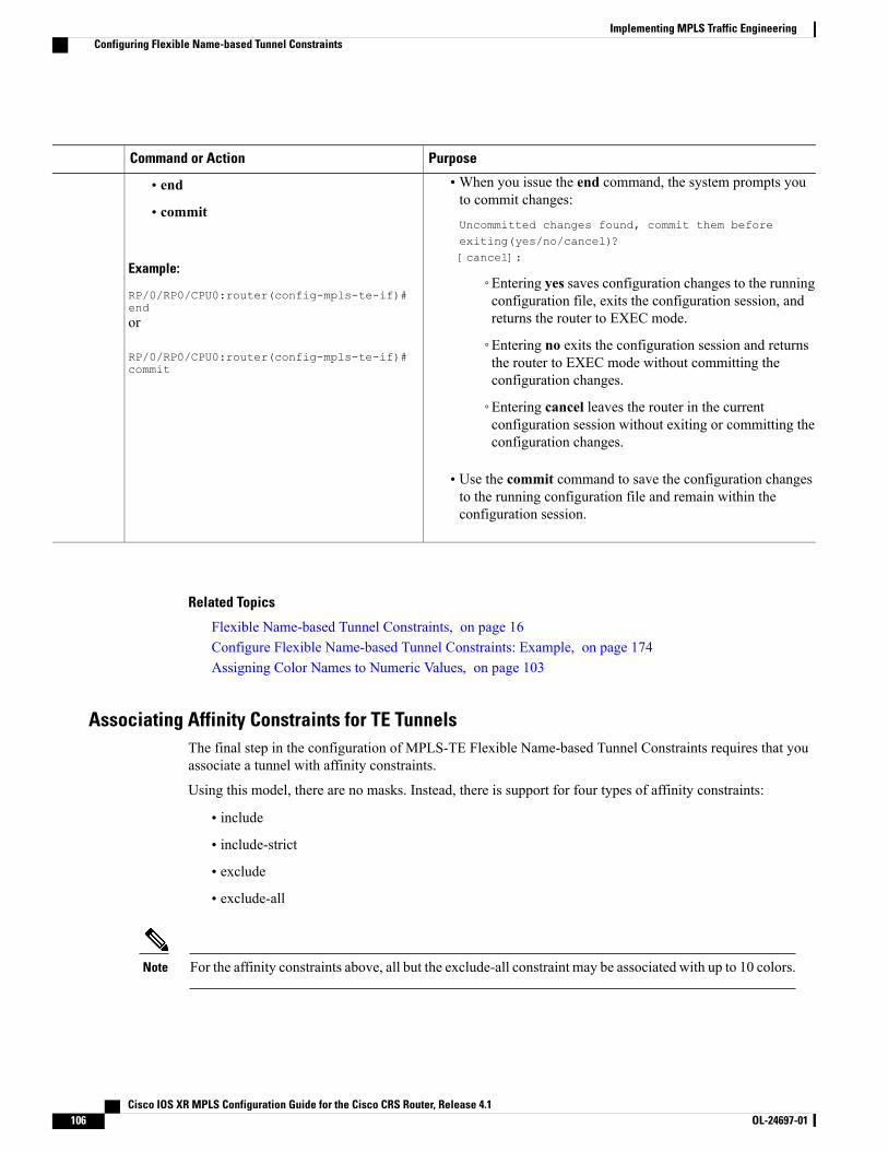
PurposeCommand or Action
•When you issue the end command, the system prompts youto commit changes:
Uncommitted changes found, commit them beforeexiting(yes/no/cancel)?[cancel]:
• end
• commit
Example:
RP/0/RP0/CPU0:router(config-mpls-te-if)#end
◦Entering yes saves configuration changes to the runningconfiguration file, exits the configuration session, andreturns the router to EXEC mode.or
RP/0/RP0/CPU0:router(config-mpls-te-if)#commit
◦Entering no exits the configuration session and returnsthe router to EXEC mode without committing theconfiguration changes.
◦Entering cancel leaves the router in the currentconfiguration session without exiting or committing theconfiguration changes.
• Use the commit command to save the configuration changesto the running configuration file and remain within theconfiguration session.
Related Topics
Flexible Name-based Tunnel Constraints, on page 16Configure Flexible Name-based Tunnel Constraints: Example, on page 174Assigning Color Names to Numeric Values, on page 103
Associating Affinity Constraints for TE TunnelsThe final step in the configuration of MPLS-TE Flexible Name-based Tunnel Constraints requires that youassociate a tunnel with affinity constraints.
Using this model, there are no masks. Instead, there is support for four types of affinity constraints:
• include
• include-strict
• exclude
• exclude-all
For the affinity constraints above, all but the exclude-all constraint may be associated with up to 10 colors.Note
Cisco IOS XR MPLS Configuration Guide for the Cisco CRS Router, Release 4.1106 OL-24697-01
Implementing MPLS Traffic EngineeringConfiguring Flexible Name-based Tunnel Constraints
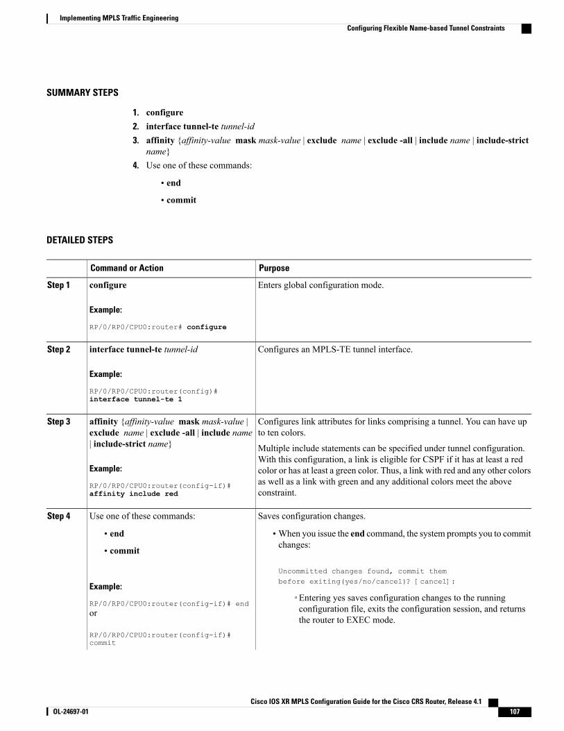
SUMMARY STEPS
1. configure2. interface tunnel-te tunnel-id3. affinity {affinity-value mask mask-value | exclude name | exclude -all | include name | include-strict
name}4. Use one of these commands:
• end
• commit
DETAILED STEPS
PurposeCommand or Action
Enters global configuration mode.configure
Example:
RP/0/RP0/CPU0:router# configure
Step 1
Configures an MPLS-TE tunnel interface.interface tunnel-te tunnel-id
Example:
RP/0/RP0/CPU0:router(config)#
Step 2
interface tunnel-te 1
Configures link attributes for links comprising a tunnel. You can have upto ten colors.
affinity {affinity-value mask mask-value |exclude name | exclude -all | include name| include-strict name}
Step 3
Multiple include statements can be specified under tunnel configuration.With this configuration, a link is eligible for CSPF if it has at least a red
Example:
RP/0/RP0/CPU0:router(config-if)#
color or has at least a green color. Thus, a link with red and any other colorsas well as a link with green and any additional colors meet the aboveconstraint.affinity include red
Saves configuration changes.Use one of these commands:Step 4
• end •When you issue the end command, the system prompts you to commitchanges:
Uncommitted changes found, commit thembefore exiting(yes/no/cancel)? [cancel]:
• commit
Example:
RP/0/RP0/CPU0:router(config-if)# end◦Entering yes saves configuration changes to the runningconfiguration file, exits the configuration session, and returnsthe router to EXEC mode.
or
RP/0/RP0/CPU0:router(config-if)#commit
Cisco IOS XR MPLS Configuration Guide for the Cisco CRS Router, Release 4.1 OL-24697-01 107
Implementing MPLS Traffic EngineeringConfiguring Flexible Name-based Tunnel Constraints
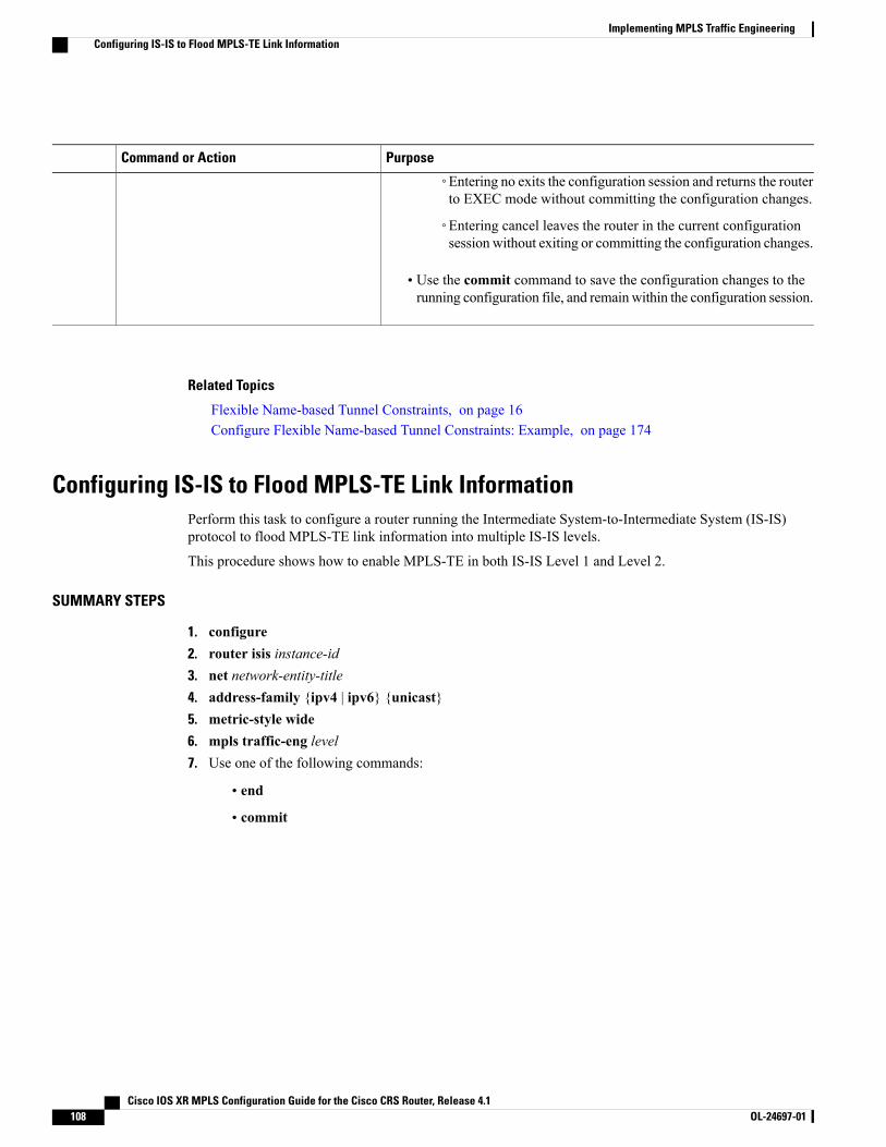
PurposeCommand or Action
◦Entering no exits the configuration session and returns the routerto EXEC mode without committing the configuration changes.
◦Entering cancel leaves the router in the current configurationsession without exiting or committing the configuration changes.
• Use the commit command to save the configuration changes to therunning configuration file, and remain within the configuration session.
Related Topics
Flexible Name-based Tunnel Constraints, on page 16Configure Flexible Name-based Tunnel Constraints: Example, on page 174
Configuring IS-IS to Flood MPLS-TE Link InformationPerform this task to configure a router running the Intermediate System-to-Intermediate System (IS-IS)protocol to flood MPLS-TE link information into multiple IS-IS levels.
This procedure shows how to enable MPLS-TE in both IS-IS Level 1 and Level 2.
SUMMARY STEPS
1. configure2. router isis instance-id3. net network-entity-title4. address-family {ipv4 | ipv6} {unicast}5. metric-style wide6. mpls traffic-eng level7. Use one of the following commands:
• end
• commit
Cisco IOS XR MPLS Configuration Guide for the Cisco CRS Router, Release 4.1108 OL-24697-01
Implementing MPLS Traffic EngineeringConfiguring IS-IS to Flood MPLS-TE Link Information
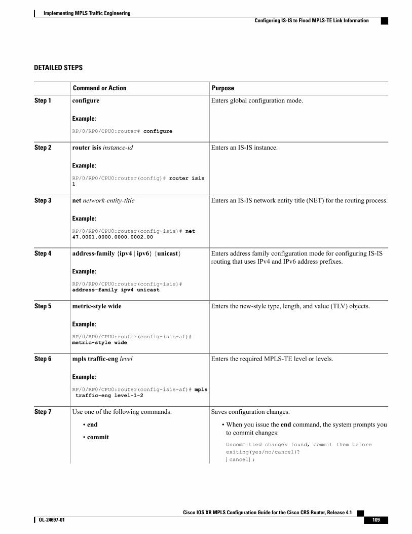
DETAILED STEPS
PurposeCommand or Action
Enters global configuration mode.configure
Example:
RP/0/RP0/CPU0:router# configure
Step 1
Enters an IS-IS instance.router isis instance-id
Example:
RP/0/RP0/CPU0:router(config)# router isis
Step 2
1
Enters an IS-IS network entity title (NET) for the routing process.net network-entity-title
Example:
RP/0/RP0/CPU0:router(config-isis)# net
Step 3
47.0001.0000.0000.0002.00
Enters address family configuration mode for configuring IS-ISrouting that uses IPv4 and IPv6 address prefixes.
address-family {ipv4 | ipv6} {unicast}
Example:
RP/0/RP0/CPU0:router(config-isis)#
Step 4
address-family ipv4 unicast
Enters the new-style type, length, and value (TLV) objects.metric-style wide
Example:
RP/0/RP0/CPU0:router(config-isis-af)#
Step 5
metric-style wide
Enters the required MPLS-TE level or levels.mpls traffic-eng level
Example:
RP/0/RP0/CPU0:router(config-isis-af)# mpls
Step 6
traffic-eng level-1-2
Saves configuration changes.Use one of the following commands:Step 7
• end •When you issue the end command, the system prompts youto commit changes:
Uncommitted changes found, commit them beforeexiting(yes/no/cancel)?[cancel]:
• commit
Cisco IOS XR MPLS Configuration Guide for the Cisco CRS Router, Release 4.1 OL-24697-01 109
Implementing MPLS Traffic EngineeringConfiguring IS-IS to Flood MPLS-TE Link Information
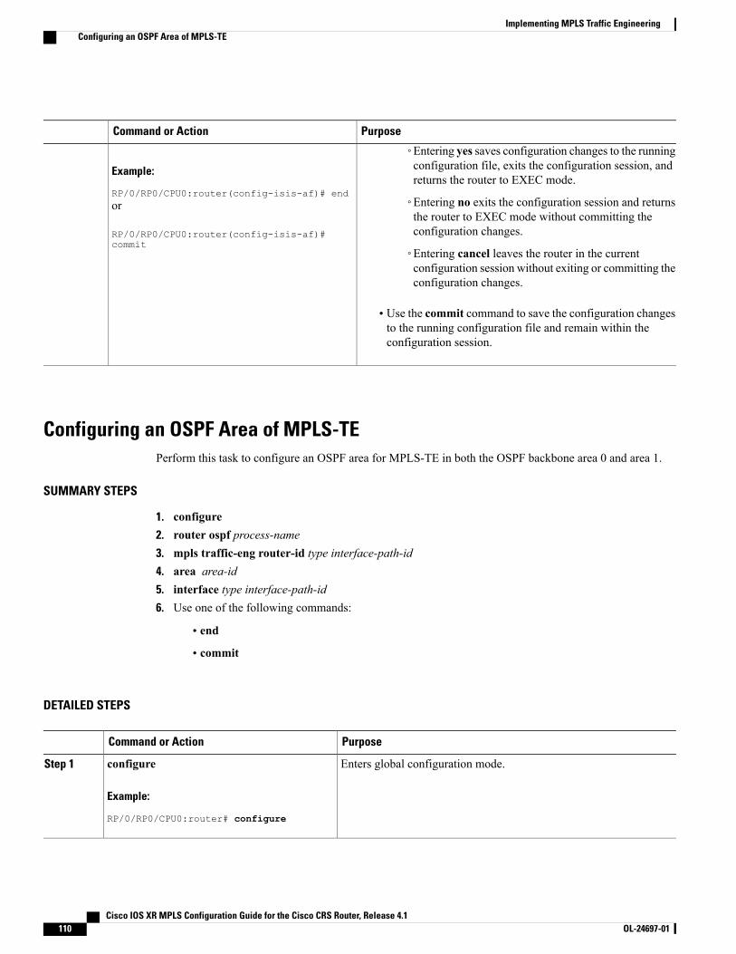
PurposeCommand or Action
Example:
RP/0/RP0/CPU0:router(config-isis-af)# end
◦Entering yes saves configuration changes to the runningconfiguration file, exits the configuration session, andreturns the router to EXEC mode.
◦Entering no exits the configuration session and returnsthe router to EXEC mode without committing theconfiguration changes.
or
RP/0/RP0/CPU0:router(config-isis-af)#commit
◦Entering cancel leaves the router in the currentconfiguration session without exiting or committing theconfiguration changes.
• Use the commit command to save the configuration changesto the running configuration file and remain within theconfiguration session.
Configuring an OSPF Area of MPLS-TEPerform this task to configure an OSPF area for MPLS-TE in both the OSPF backbone area 0 and area 1.
SUMMARY STEPS
1. configure2. router ospf process-name3. mpls traffic-eng router-id type interface-path-id4. area area-id5. interface type interface-path-id6. Use one of the following commands:
• end
• commit
DETAILED STEPS
PurposeCommand or Action
Enters global configuration mode.configure
Example:
RP/0/RP0/CPU0:router# configure
Step 1
Cisco IOS XR MPLS Configuration Guide for the Cisco CRS Router, Release 4.1110 OL-24697-01
Implementing MPLS Traffic EngineeringConfiguring an OSPF Area of MPLS-TE
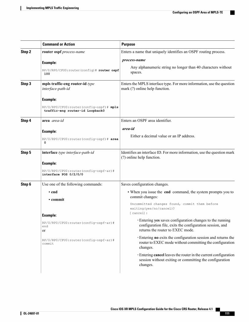
PurposeCommand or Action
Enters a name that uniquely identifies an OSPF routing process.router ospf process-name
Example:
RP/0/RP0/CPU0:router(config)# router ospf
Step 2
process-name
Any alphanumeric string no longer than 40 characters withoutspaces.100
Enters theMPLS interface type. For more information, use the questionmark (?) online help function.
mpls traffic-eng router-id typeinterface-path-id
Example:
RP/0/RP0/CPU0:router(config-ospf)# mpls
Step 3
traffic-eng router-id Loopback0
Enters an OSPF area identifier.area area-id
Example:
RP/0/RP0/CPU0:router(config-ospf)# area
Step 4
area-id
Either a decimal value or an IP address.0
Identifies an interface ID. For more information, use the question mark(?) online help function.
interface type interface-path-id
Example:
RP/0/RP0/CPU0:router(config-ospf-ar)#
Step 5
interface POS 0/2/0/0
Saves configuration changes.Use one of the following commands:Step 6
• end •When you issue the end command, the system prompts you tocommit changes:
Uncommitted changes found, commit them beforeexiting(yes/no/cancel)?[cancel]:
• commit
Example:
RP/0/RP0/CPU0:router(config-ospf-ar)#end
◦Entering yes saves configuration changes to the runningconfiguration file, exits the configuration session, andreturns the router to EXEC mode.or
RP/0/RP0/CPU0:router(config-ospf-ar)#commit
◦Entering no exits the configuration session and returns therouter to EXECmode without committing the configurationchanges.
◦Entering cancel leaves the router in the current configurationsession without exiting or committing the configurationchanges.
Cisco IOS XR MPLS Configuration Guide for the Cisco CRS Router, Release 4.1 OL-24697-01 111
Implementing MPLS Traffic EngineeringConfiguring an OSPF Area of MPLS-TE
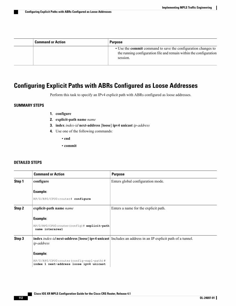
PurposeCommand or Action
• Use the commit command to save the configuration changes tothe running configuration file and remain within the configurationsession.
Configuring Explicit Paths with ABRs Configured as Loose AddressesPerform this task to specify an IPv4 explicit path with ABRs configured as loose addresses.
SUMMARY STEPS
1. configure2. explicit-path name name3. index index-id next-address [loose] ipv4 unicast ip-address4. Use one of the following commands:
• end
• commit
DETAILED STEPS
PurposeCommand or Action
Enters global configuration mode.configure
Example:
RP/0/RP0/CPU0:router# configure
Step 1
Enters a name for the explicit path.explicit-path name name
Example:
RP/0/RP0/CPU0:router(config)# explicit-path
Step 2
name interarea1
Includes an address in an IP explicit path of a tunnel.index index-id next-address [loose] ipv4 unicastip-address
Step 3
Example:
RP/0/RP0/CPU0:router(config-expl-path)#index 1 next-address loose ipv4 unicast
Cisco IOS XR MPLS Configuration Guide for the Cisco CRS Router, Release 4.1112 OL-24697-01
Implementing MPLS Traffic EngineeringConfiguring Explicit Paths with ABRs Configured as Loose Addresses
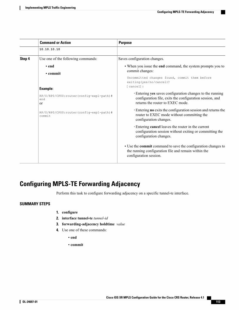
PurposeCommand or Action
10.10.10.10
Saves configuration changes.Use one of the following commands:Step 4
• end •When you issue the end command, the system prompts you tocommit changes:
Uncommitted changes found, commit them beforeexiting(yes/no/cancel)?[cancel]:
• commit
Example:
RP/0/RP0/CPU0:router(config-expl-path)#end
◦Entering yes saves configuration changes to the runningconfiguration file, exits the configuration session, andreturns the router to EXEC mode.or
RP/0/RP0/CPU0:router(config-expl-path)#commit
◦Entering no exits the configuration session and returns therouter to EXEC mode without committing theconfiguration changes.
◦Entering cancel leaves the router in the currentconfiguration session without exiting or committing theconfiguration changes.
• Use the commit command to save the configuration changes tothe running configuration file and remain within theconfiguration session.
Configuring MPLS-TE Forwarding AdjacencyPerform this task to configure forwarding adjacency on a specific tunnel-te interface.
SUMMARY STEPS
1. configure2. interface tunnel-te tunnel-id3. forwarding-adjacency holdtime value4. Use one of these commands:
• end
• commit
Cisco IOS XR MPLS Configuration Guide for the Cisco CRS Router, Release 4.1 OL-24697-01 113
Implementing MPLS Traffic EngineeringConfiguring MPLS-TE Forwarding Adjacency
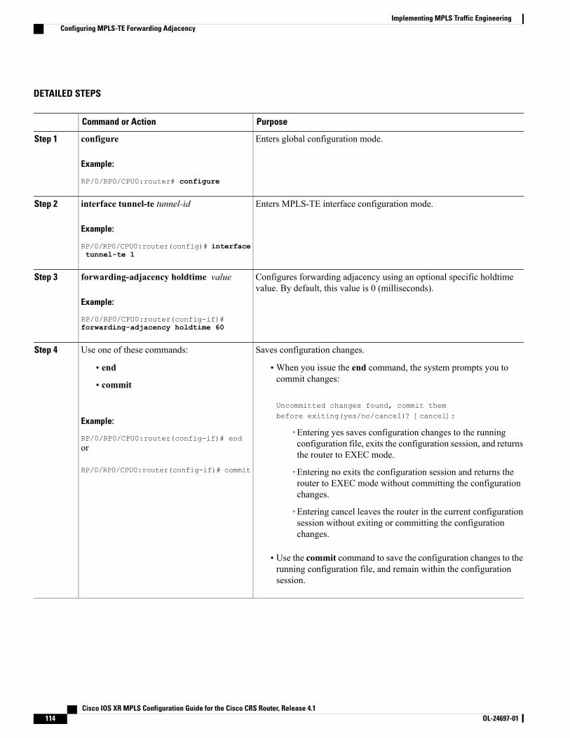
DETAILED STEPS
PurposeCommand or Action
Enters global configuration mode.configure
Example:
RP/0/RP0/CPU0:router# configure
Step 1
Enters MPLS-TE interface configuration mode.interface tunnel-te tunnel-id
Example:
RP/0/RP0/CPU0:router(config)# interface
Step 2
tunnel-te 1
Configures forwarding adjacency using an optional specific holdtimevalue. By default, this value is 0 (milliseconds).
forwarding-adjacency holdtime value
Example:
RP/0/RP0/CPU0:router(config-if)#
Step 3
forwarding-adjacency holdtime 60
Saves configuration changes.Use one of these commands:Step 4
• end •When you issue the end command, the system prompts you tocommit changes:
Uncommitted changes found, commit thembefore exiting(yes/no/cancel)? [cancel]:
• commit
Example:
RP/0/RP0/CPU0:router(config-if)# end◦Entering yes saves configuration changes to the runningconfiguration file, exits the configuration session, and returnsthe router to EXEC mode.
or
RP/0/RP0/CPU0:router(config-if)# commit ◦Entering no exits the configuration session and returns therouter to EXEC mode without committing the configurationchanges.
◦Entering cancel leaves the router in the current configurationsession without exiting or committing the configurationchanges.
• Use the commit command to save the configuration changes to therunning configuration file, and remain within the configurationsession.
Cisco IOS XR MPLS Configuration Guide for the Cisco CRS Router, Release 4.1114 OL-24697-01
Implementing MPLS Traffic EngineeringConfiguring MPLS-TE Forwarding Adjacency
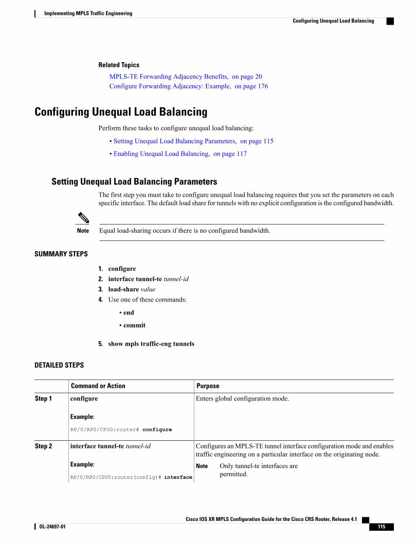
Related Topics
MPLS-TE Forwarding Adjacency Benefits, on page 20Configure Forwarding Adjacency: Example, on page 176
Configuring Unequal Load BalancingPerform these tasks to configure unequal load balancing:
• Setting Unequal Load Balancing Parameters, on page 115
• Enabling Unequal Load Balancing, on page 117
Setting Unequal Load Balancing ParametersThe first step you must take to configure unequal load balancing requires that you set the parameters on eachspecific interface. The default load share for tunnels with no explicit configuration is the configured bandwidth.
Equal load-sharing occurs if there is no configured bandwidth.Note
SUMMARY STEPS
1. configure2. interface tunnel-te tunnel-id3. load-share value4. Use one of these commands:
• end
• commit
5. show mpls traffic-eng tunnels
DETAILED STEPS
PurposeCommand or Action
Enters global configuration mode.configure
Example:
RP/0/RP0/CPU0:router# configure
Step 1
Configures anMPLS-TE tunnel interface configuration mode and enablestraffic engineering on a particular interface on the originating node.
interface tunnel-te tunnel-id
Example:
RP/0/RP0/CPU0:router(config)# interface
Step 2
Only tunnel-te interfaces arepermitted.
Note
Cisco IOS XR MPLS Configuration Guide for the Cisco CRS Router, Release 4.1 OL-24697-01 115
Implementing MPLS Traffic EngineeringConfiguring Unequal Load Balancing
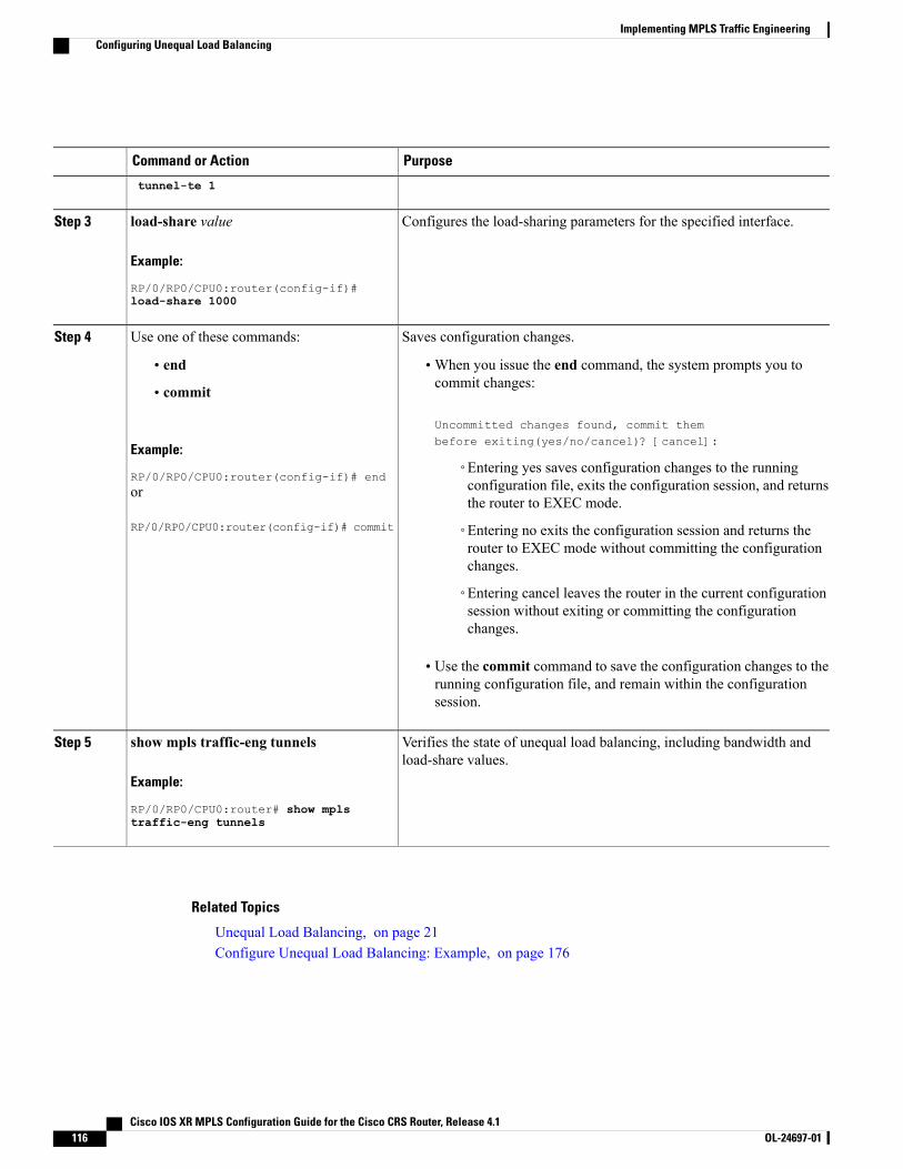
PurposeCommand or Action
tunnel-te 1
Configures the load-sharing parameters for the specified interface.load-share value
Example:
RP/0/RP0/CPU0:router(config-if)#
Step 3
load-share 1000
Saves configuration changes.Use one of these commands:Step 4
• end •When you issue the end command, the system prompts you tocommit changes:
Uncommitted changes found, commit thembefore exiting(yes/no/cancel)? [cancel]:
• commit
Example:
RP/0/RP0/CPU0:router(config-if)# end◦Entering yes saves configuration changes to the runningconfiguration file, exits the configuration session, and returnsthe router to EXEC mode.
or
RP/0/RP0/CPU0:router(config-if)# commit ◦Entering no exits the configuration session and returns therouter to EXEC mode without committing the configurationchanges.
◦Entering cancel leaves the router in the current configurationsession without exiting or committing the configurationchanges.
• Use the commit command to save the configuration changes to therunning configuration file, and remain within the configurationsession.
Verifies the state of unequal load balancing, including bandwidth andload-share values.
show mpls traffic-eng tunnels
Example:
RP/0/RP0/CPU0:router# show mpls
Step 5
traffic-eng tunnels
Related Topics
Unequal Load Balancing, on page 21Configure Unequal Load Balancing: Example, on page 176
Cisco IOS XR MPLS Configuration Guide for the Cisco CRS Router, Release 4.1116 OL-24697-01
Implementing MPLS Traffic EngineeringConfiguring Unequal Load Balancing
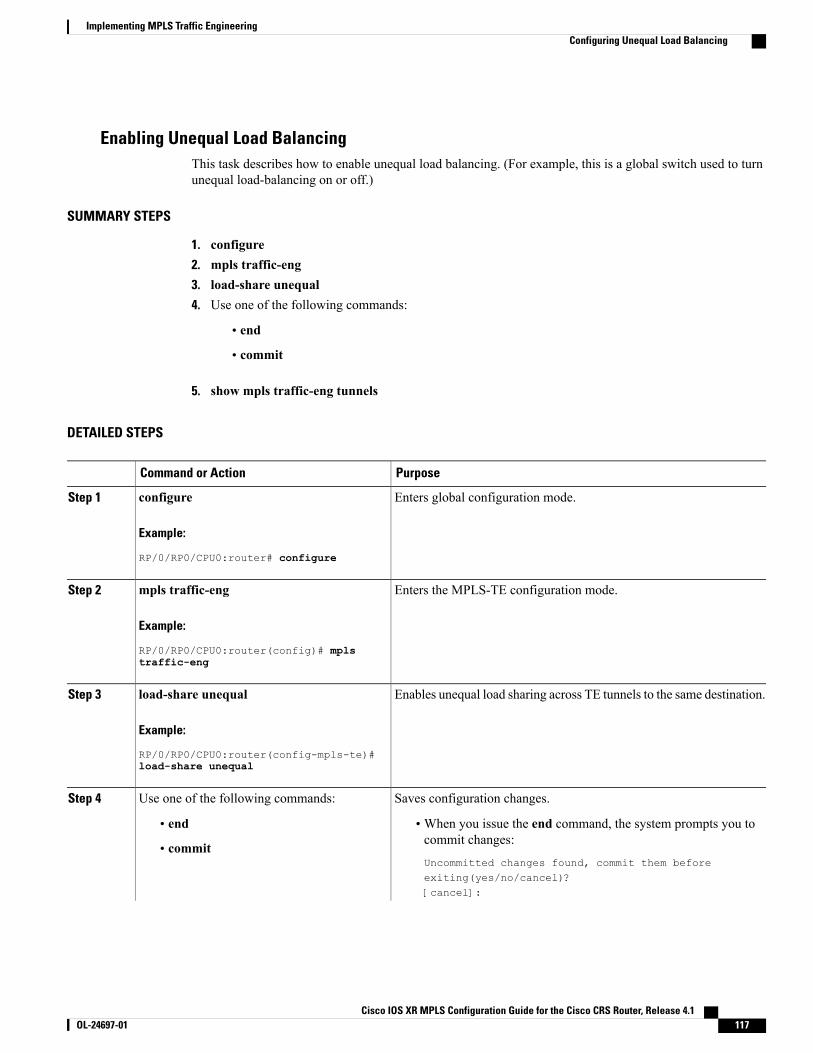
Enabling Unequal Load BalancingThis task describes how to enable unequal load balancing. (For example, this is a global switch used to turnunequal load-balancing on or off.)
SUMMARY STEPS
1. configure2. mpls traffic-eng3. load-share unequal4. Use one of the following commands:
• end
• commit
5. show mpls traffic-eng tunnels
DETAILED STEPS
PurposeCommand or Action
Enters global configuration mode.configure
Example:
RP/0/RP0/CPU0:router# configure
Step 1
Enters the MPLS-TE configuration mode.mpls traffic-eng
Example:
RP/0/RP0/CPU0:router(config)# mpls
Step 2
traffic-eng
Enables unequal load sharing across TE tunnels to the same destination.load-share unequal
Example:
RP/0/RP0/CPU0:router(config-mpls-te)#
Step 3
load-share unequal
Saves configuration changes.Use one of the following commands:Step 4
• end •When you issue the end command, the system prompts you tocommit changes:
Uncommitted changes found, commit them beforeexiting(yes/no/cancel)?[cancel]:
• commit
Cisco IOS XR MPLS Configuration Guide for the Cisco CRS Router, Release 4.1 OL-24697-01 117
Implementing MPLS Traffic EngineeringConfiguring Unequal Load Balancing
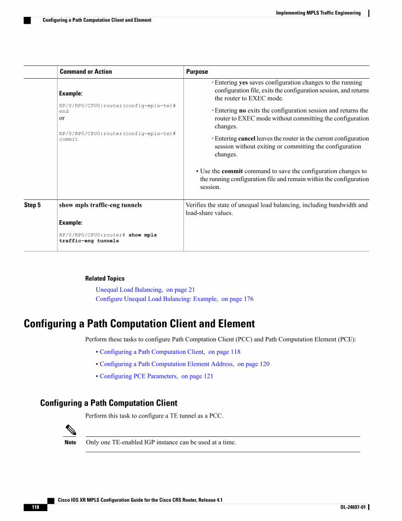
PurposeCommand or Action
Example:
RP/0/RP0/CPU0:router(config-mpls-te)#end
◦Entering yes saves configuration changes to the runningconfiguration file, exits the configuration session, and returnsthe router to EXEC mode.
◦Entering no exits the configuration session and returns therouter to EXECmode without committing the configurationchanges.
or
RP/0/RP0/CPU0:router(config-mpls-te)#commit ◦Entering cancel leaves the router in the current configuration
session without exiting or committing the configurationchanges.
• Use the commit command to save the configuration changes tothe running configuration file and remain within the configurationsession.
Verifies the state of unequal load balancing, including bandwidth andload-share values.
show mpls traffic-eng tunnels
Example:
RP/0/RP0/CPU0:router# show mpls
Step 5
traffic-eng tunnels
Related Topics
Unequal Load Balancing, on page 21Configure Unequal Load Balancing: Example, on page 176
Configuring a Path Computation Client and ElementPerform these tasks to configure Path Comptation Client (PCC) and Path Computation Element (PCE):
• Configuring a Path Computation Client, on page 118
• Configuring a Path Computation Element Address, on page 120
• Configuring PCE Parameters, on page 121
Configuring a Path Computation ClientPerform this task to configure a TE tunnel as a PCC.
Only one TE-enabled IGP instance can be used at a time.Note
Cisco IOS XR MPLS Configuration Guide for the Cisco CRS Router, Release 4.1118 OL-24697-01
Implementing MPLS Traffic EngineeringConfiguring a Path Computation Client and Element
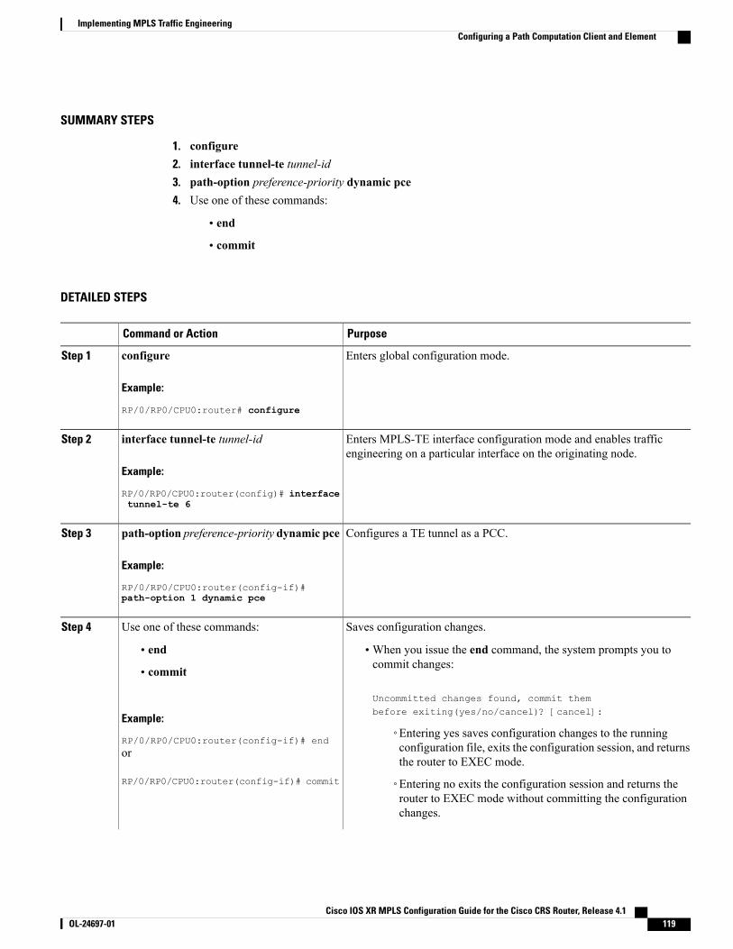
SUMMARY STEPS
1. configure2. interface tunnel-te tunnel-id3. path-option preference-priority dynamic pce4. Use one of these commands:
• end
• commit
DETAILED STEPS
PurposeCommand or Action
Enters global configuration mode.configure
Example:
RP/0/RP0/CPU0:router# configure
Step 1
Enters MPLS-TE interface configuration mode and enables trafficengineering on a particular interface on the originating node.
interface tunnel-te tunnel-id
Example:
RP/0/RP0/CPU0:router(config)# interface
Step 2
tunnel-te 6
Configures a TE tunnel as a PCC.path-option preference-priority dynamic pce
Example:
RP/0/RP0/CPU0:router(config-if)#
Step 3
path-option 1 dynamic pce
Saves configuration changes.Use one of these commands:Step 4
• end •When you issue the end command, the system prompts you tocommit changes:
Uncommitted changes found, commit thembefore exiting(yes/no/cancel)? [cancel]:
• commit
Example:
RP/0/RP0/CPU0:router(config-if)# end◦Entering yes saves configuration changes to the runningconfiguration file, exits the configuration session, and returnsthe router to EXEC mode.
or
RP/0/RP0/CPU0:router(config-if)# commit ◦Entering no exits the configuration session and returns therouter to EXEC mode without committing the configurationchanges.
Cisco IOS XR MPLS Configuration Guide for the Cisco CRS Router, Release 4.1 OL-24697-01 119
Implementing MPLS Traffic EngineeringConfiguring a Path Computation Client and Element
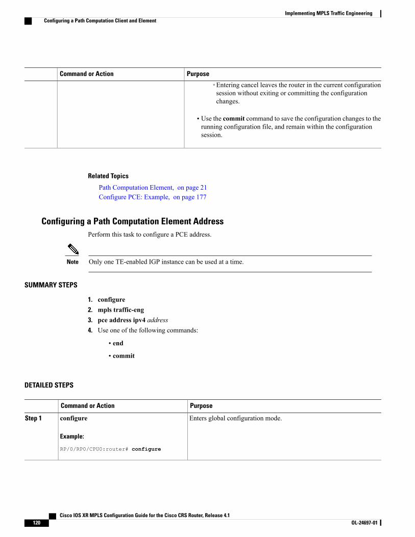
PurposeCommand or Action
◦Entering cancel leaves the router in the current configurationsession without exiting or committing the configurationchanges.
• Use the commit command to save the configuration changes to therunning configuration file, and remain within the configurationsession.
Related Topics
Path Computation Element, on page 21Configure PCE: Example, on page 177
Configuring a Path Computation Element AddressPerform this task to configure a PCE address.
Only one TE-enabled IGP instance can be used at a time.Note
SUMMARY STEPS
1. configure2. mpls traffic-eng3. pce address ipv4 address4. Use one of the following commands:
• end
• commit
DETAILED STEPS
PurposeCommand or Action
Enters global configuration mode.configure
Example:
RP/0/RP0/CPU0:router# configure
Step 1
Cisco IOS XR MPLS Configuration Guide for the Cisco CRS Router, Release 4.1120 OL-24697-01
Implementing MPLS Traffic EngineeringConfiguring a Path Computation Client and Element
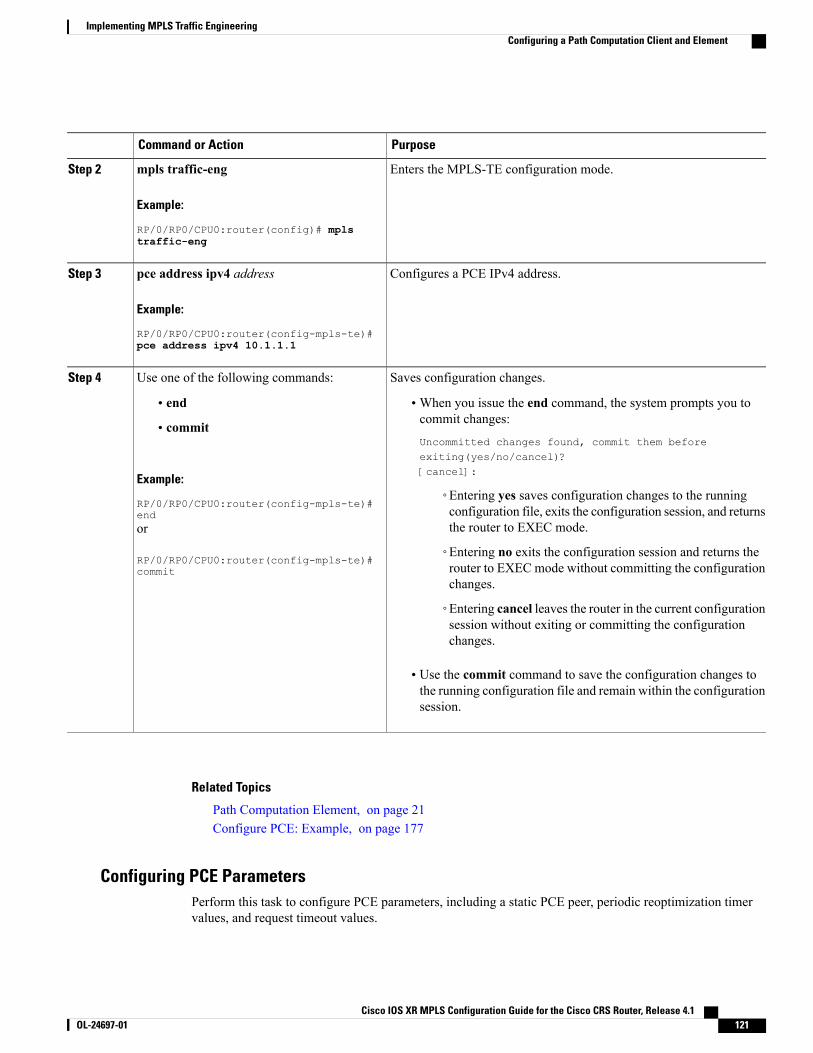
PurposeCommand or Action
Enters the MPLS-TE configuration mode.mpls traffic-eng
Example:
RP/0/RP0/CPU0:router(config)# mpls
Step 2
traffic-eng
Configures a PCE IPv4 address.pce address ipv4 address
Example:
RP/0/RP0/CPU0:router(config-mpls-te)#
Step 3
pce address ipv4 10.1.1.1
Saves configuration changes.Use one of the following commands:Step 4
• end •When you issue the end command, the system prompts you tocommit changes:
Uncommitted changes found, commit them beforeexiting(yes/no/cancel)?[cancel]:
• commit
Example:
RP/0/RP0/CPU0:router(config-mpls-te)#end
◦Entering yes saves configuration changes to the runningconfiguration file, exits the configuration session, and returnsthe router to EXEC mode.or
RP/0/RP0/CPU0:router(config-mpls-te)#commit
◦Entering no exits the configuration session and returns therouter to EXEC mode without committing the configurationchanges.
◦Entering cancel leaves the router in the current configurationsession without exiting or committing the configurationchanges.
• Use the commit command to save the configuration changes tothe running configuration file and remain within the configurationsession.
Related Topics
Path Computation Element, on page 21Configure PCE: Example, on page 177
Configuring PCE ParametersPerform this task to configure PCE parameters, including a static PCE peer, periodic reoptimization timervalues, and request timeout values.
Cisco IOS XR MPLS Configuration Guide for the Cisco CRS Router, Release 4.1 OL-24697-01 121
Implementing MPLS Traffic EngineeringConfiguring a Path Computation Client and Element
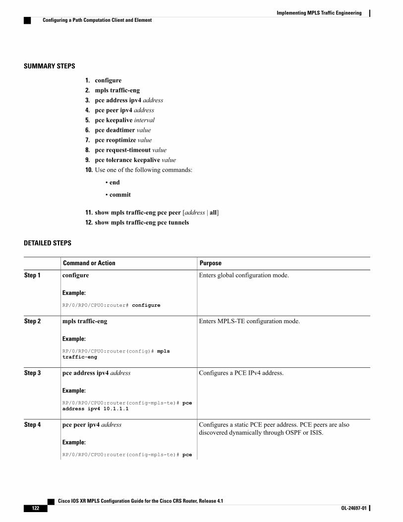
SUMMARY STEPS
1. configure2. mpls traffic-eng3. pce address ipv4 address4. pce peer ipv4 address5. pce keepalive interval6. pce deadtimer value7. pce reoptimize value8. pce request-timeout value9. pce tolerance keepalive value10. Use one of the following commands:
• end
• commit
11. show mpls traffic-eng pce peer [address | all]12. show mpls traffic-eng pce tunnels
DETAILED STEPS
PurposeCommand or Action
Enters global configuration mode.configure
Example:
RP/0/RP0/CPU0:router# configure
Step 1
Enters MPLS-TE configuration mode.mpls traffic-eng
Example:
RP/0/RP0/CPU0:router(config)# mpls
Step 2
traffic-eng
Configures a PCE IPv4 address.pce address ipv4 address
Example:
RP/0/RP0/CPU0:router(config-mpls-te)# pce
Step 3
address ipv4 10.1.1.1
Configures a static PCE peer address. PCE peers are alsodiscovered dynamically through OSPF or ISIS.
pce peer ipv4 address
Example:
RP/0/RP0/CPU0:router(config-mpls-te)# pce
Step 4
Cisco IOS XR MPLS Configuration Guide for the Cisco CRS Router, Release 4.1122 OL-24697-01
Implementing MPLS Traffic EngineeringConfiguring a Path Computation Client and Element
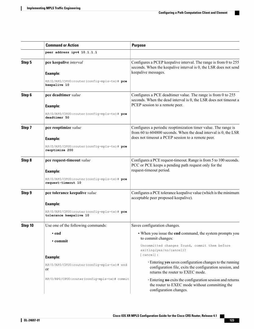
PurposeCommand or Action
peer address ipv4 10.1.1.1
Configures a PCEP keepalive interval. The range is from 0 to 255seconds. When the keepalive interval is 0, the LSR does not sendkeepalive messages.
pce keepalive interval
Example:
RP/0/RP0/CPU0:router(config-mpls-te)# pce
Step 5
keepalive 10
Configures a PCE deadtimer value. The range is from 0 to 255seconds. When the dead interval is 0, the LSR does not timeout aPCEP session to a remote peer.
pce deadtimer value
Example:
RP/0/RP0/CPU0:router(config-mpls-te)# pce
Step 6
deadtimer 50
Configures a periodic reoptimization timer value. The range isfrom 60 to 604800 seconds. When the dead interval is 0, the LSRdoes not timeout a PCEP session to a remote peer.
pce reoptimize value
Example:
RP/0/RP0/CPU0:router(config-mpls-te)# pce
Step 7
reoptimize 200
Configures a PCE request-timeout. Range is from 5 to 100 seconds.PCC or PCE keeps a pending path request only for therequest-timeout period.
pce request-timeout value
Example:
RP/0/RP0/CPU0:router(config-mpls-te)# pce
Step 8
request-timeout 10
Configures a PCE tolerance keepalive value (which is theminimumacceptable peer proposed keepalive).
pce tolerance keepalive value
Example:
RP/0/RP0/CPU0:router(config-mpls-te)# pce
Step 9
tolerance keepalive 10
Saves configuration changes.Use one of the following commands:Step 10
• end •When you issue the end command, the system prompts youto commit changes:
Uncommitted changes found, commit them beforeexiting(yes/no/cancel)?[cancel]:
• commit
Example:
RP/0/RP0/CPU0:router(config-mpls-te)# end◦Entering yes saves configuration changes to the runningconfiguration file, exits the configuration session, andreturns the router to EXEC mode.
or
RP/0/RP0/CPU0:router(config-mpls-te)# commit ◦Entering no exits the configuration session and returnsthe router to EXEC mode without committing theconfiguration changes.
Cisco IOS XR MPLS Configuration Guide for the Cisco CRS Router, Release 4.1 OL-24697-01 123
Implementing MPLS Traffic EngineeringConfiguring a Path Computation Client and Element
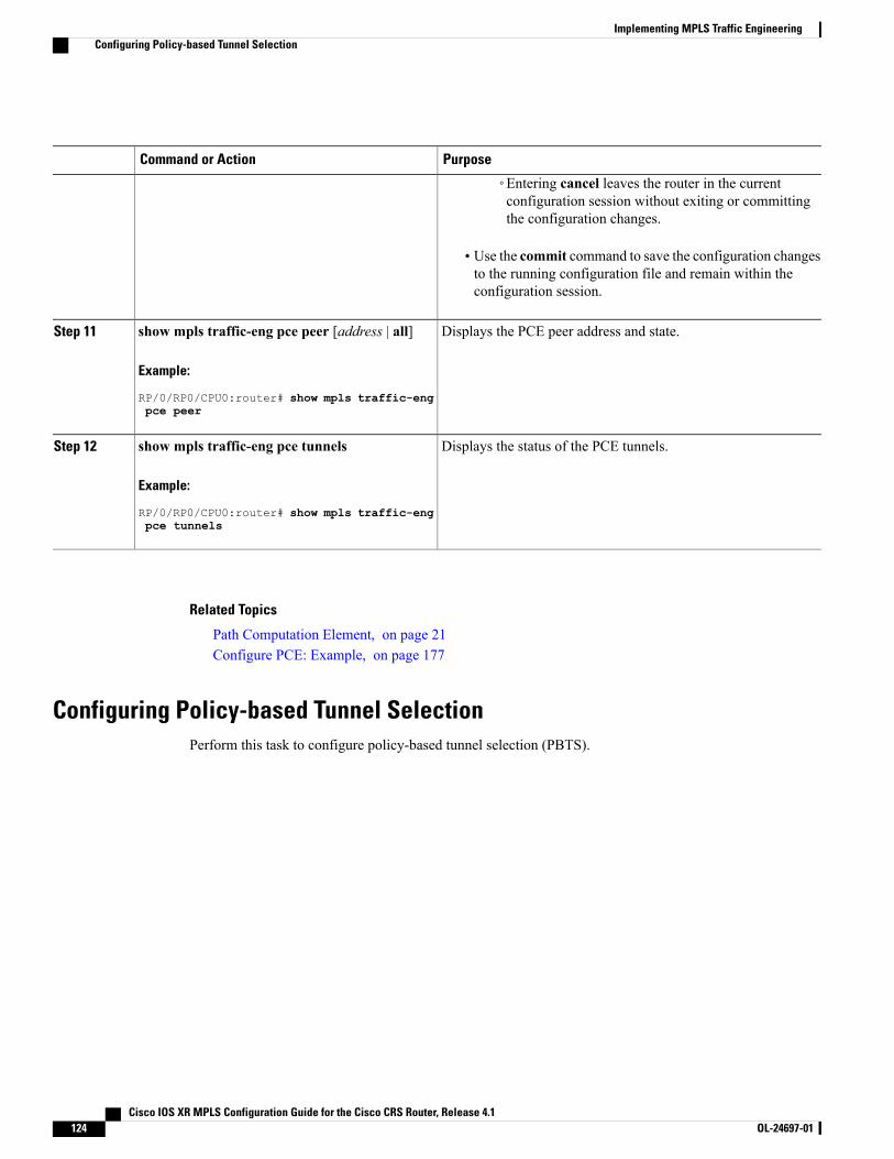
PurposeCommand or Action
◦Entering cancel leaves the router in the currentconfiguration session without exiting or committingthe configuration changes.
• Use the commit command to save the configuration changesto the running configuration file and remain within theconfiguration session.
Displays the PCE peer address and state.show mpls traffic-eng pce peer [address | all]
Example:
RP/0/RP0/CPU0:router# show mpls traffic-eng
Step 11
pce peer
Displays the status of the PCE tunnels.show mpls traffic-eng pce tunnels
Example:
RP/0/RP0/CPU0:router# show mpls traffic-eng
Step 12
pce tunnels
Related Topics
Path Computation Element, on page 21Configure PCE: Example, on page 177
Configuring Policy-based Tunnel SelectionPerform this task to configure policy-based tunnel selection (PBTS).
Cisco IOS XR MPLS Configuration Guide for the Cisco CRS Router, Release 4.1124 OL-24697-01
Implementing MPLS Traffic EngineeringConfiguring Policy-based Tunnel Selection
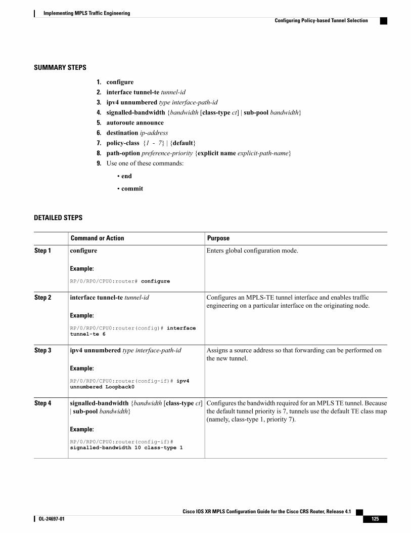
SUMMARY STEPS
1. configure2. interface tunnel-te tunnel-id3. ipv4 unnumbered type interface-path-id4. signalled-bandwidth {bandwidth [class-type ct] | sub-pool bandwidth}5. autoroute announce6. destination ip-address7. policy-class {1 - 7} | {default}8. path-option preference-priority {explicit name explicit-path-name}9. Use one of these commands:
• end
• commit
DETAILED STEPS
PurposeCommand or Action
Enters global configuration mode.configure
Example:
RP/0/RP0/CPU0:router# configure
Step 1
Configures an MPLS-TE tunnel interface and enables trafficengineering on a particular interface on the originating node.
interface tunnel-te tunnel-id
Example:
RP/0/RP0/CPU0:router(config)# interface
Step 2
tunnel-te 6
Assigns a source address so that forwarding can be performed onthe new tunnel.
ipv4 unnumbered type interface-path-id
Example:
RP/0/RP0/CPU0:router(config-if)# ipv4
Step 3
unnumbered Loopback0
Configures the bandwidth required for anMPLS TE tunnel. Becausethe default tunnel priority is 7, tunnels use the default TE class map(namely, class-type 1, priority 7).
signalled-bandwidth {bandwidth [class-type ct]| sub-pool bandwidth}
Example:
RP/0/RP0/CPU0:router(config-if)#
Step 4
signalled-bandwidth 10 class-type 1
Cisco IOS XR MPLS Configuration Guide for the Cisco CRS Router, Release 4.1 OL-24697-01 125
Implementing MPLS Traffic EngineeringConfiguring Policy-based Tunnel Selection
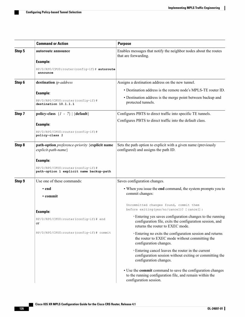
PurposeCommand or Action
Enables messages that notify the neighbor nodes about the routesthat are forwarding.
autoroute announce
Example:
RP/0/RP0/CPU0:router(config-if)# autoroute
Step 5
announce
Assigns a destination address on the new tunnel.destination ip-addressStep 6
Example:
RP/0/RP0/CPU0:router(config-if)#
• Destination address is the remote node’s MPLS-TE router ID.
• Destination address is the merge point between backup andprotected tunnels.destination 10.1.1.1
Configures PBTS to direct traffic into specific TE tunnels.policy-class {1 - 7} | {default}Step 7
Example:
RP/0/RP0/CPU0:router(config-if)#
Configures PBTS to direct traffic into the default class.
policy-class 1
Sets the path option to explicit with a given name (previouslyconfigured) and assigns the path ID.
path-option preference-priority {explicit nameexplicit-path-name}
Example:
RP/0/RP0/CPU0:router(config-if)#
Step 8
path-option l explicit name backup-path
Saves configuration changes.Use one of these commands:Step 9
• end •When you issue the end command, the system prompts you tocommit changes:
Uncommitted changes found, commit thembefore exiting(yes/no/cancel)? [cancel]:
• commit
Example:
RP/0/RP0/CPU0:router(config-if)# end◦Entering yes saves configuration changes to the runningconfiguration file, exits the configuration session, andreturns the router to EXEC mode.
or
RP/0/RP0/CPU0:router(config-if)# commit ◦Entering no exits the configuration session and returnsthe router to EXEC mode without committing theconfiguration changes.
◦Entering cancel leaves the router in the currentconfiguration session without exiting or committing theconfiguration changes.
• Use the commit command to save the configuration changesto the running configuration file, and remain within theconfiguration session.
Cisco IOS XR MPLS Configuration Guide for the Cisco CRS Router, Release 4.1126 OL-24697-01
Implementing MPLS Traffic EngineeringConfiguring Policy-based Tunnel Selection
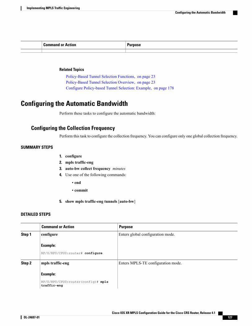
PurposeCommand or Action
Related Topics
Policy-Based Tunnel Selection Functions, on page 23Policy-Based Tunnel Selection Overview, on page 23Configure Policy-based Tunnel Selection: Example, on page 178
Configuring the Automatic BandwidthPerform these tasks to configure the automatic bandwidth:
Configuring the Collection FrequencyPerform this task to configure the collection frequency. You can configure only one global collection frequency.
SUMMARY STEPS
1. configure2. mpls traffic-eng3. auto-bw collect frequency minutes4. Use one of the following commands:
• end
• commit
5. show mpls traffic-eng tunnels [auto-bw]
DETAILED STEPS
PurposeCommand or Action
Enters global configuration mode.configure
Example:
RP/0/RP0/CPU0:router# configure
Step 1
Enters MPLS-TE configuration mode.mpls traffic-eng
Example:
RP/0/RP0/CPU0:router(config)# mpls
Step 2
traffic-eng
Cisco IOS XR MPLS Configuration Guide for the Cisco CRS Router, Release 4.1 OL-24697-01 127
Implementing MPLS Traffic EngineeringConfiguring the Automatic Bandwidth
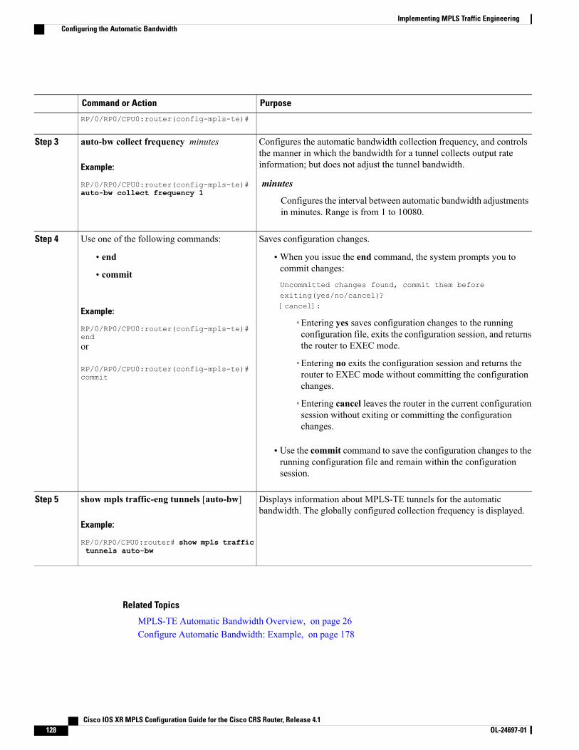
PurposeCommand or Action
RP/0/RP0/CPU0:router(config-mpls-te)#
Configures the automatic bandwidth collection frequency, and controlsthe manner in which the bandwidth for a tunnel collects output rateinformation; but does not adjust the tunnel bandwidth.
auto-bw collect frequency minutes
Example:
RP/0/RP0/CPU0:router(config-mpls-te)#
Step 3
minutesauto-bw collect frequency 1
Configures the interval between automatic bandwidth adjustmentsin minutes. Range is from 1 to 10080.
Saves configuration changes.Use one of the following commands:Step 4
• end •When you issue the end command, the system prompts you tocommit changes:
Uncommitted changes found, commit them beforeexiting(yes/no/cancel)?[cancel]:
• commit
Example:
RP/0/RP0/CPU0:router(config-mpls-te)#end
◦Entering yes saves configuration changes to the runningconfiguration file, exits the configuration session, and returnsthe router to EXEC mode.or
RP/0/RP0/CPU0:router(config-mpls-te)#commit
◦Entering no exits the configuration session and returns therouter to EXEC mode without committing the configurationchanges.
◦Entering cancel leaves the router in the current configurationsession without exiting or committing the configurationchanges.
• Use the commit command to save the configuration changes to therunning configuration file and remain within the configurationsession.
Displays information about MPLS-TE tunnels for the automaticbandwidth. The globally configured collection frequency is displayed.
show mpls traffic-eng tunnels [auto-bw]
Example:
RP/0/RP0/CPU0:router# show mpls traffic
Step 5
tunnels auto-bw
Related Topics
MPLS-TE Automatic Bandwidth Overview, on page 26Configure Automatic Bandwidth: Example, on page 178
Cisco IOS XR MPLS Configuration Guide for the Cisco CRS Router, Release 4.1128 OL-24697-01
Implementing MPLS Traffic EngineeringConfiguring the Automatic Bandwidth
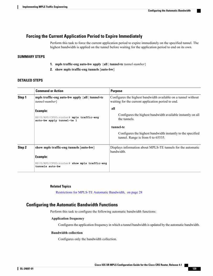
Forcing the Current Application Period to Expire ImmediatelyPerform this task to force the current application period to expire immediately on the specified tunnel. Thehighest bandwidth is applied on the tunnel before waiting for the application period to end on its own.
SUMMARY STEPS
1. mpls traffic-eng auto-bw apply {all | tunnel-te tunnel-number}2. show mpls traffic-eng tunnels [auto-bw]
DETAILED STEPS
PurposeCommand or Action
Configures the highest bandwidth available on a tunnel withoutwaiting for the current application period to end.
mpls traffic-eng auto-bw apply {all | tunnel-tetunnel-number}
Example:
RP/0/RP0/CPU0:router# mpls traffic-eng
Step 1
all
Configures the highest bandwidth available instantly on allthe tunnels.auto-bw apply tunnel-te 1
tunnel-te
Configures the highest bandwidth instantly to the specifiedtunnel. Range is from 0 to 65535.
Displays information about MPLS-TE tunnels for the automaticbandwidth.
show mpls traffic-eng tunnels [auto-bw]
Example:
RP/0/RP0/CPU0:router# show mpls traffic-eng
Step 2
tunnels auto-bw
Related Topics
Restrictions for MPLS-TE Automatic Bandwidth, on page 28
Configuring the Automatic Bandwidth FunctionsPerform this task to configure the following automatic bandwidth functions:
Application frequency
Configures the application frequency in which a tunnel bandwidth is updated by the automatic bandwidth.
Bandwidth collection
Configures only the bandwidth collection.
Cisco IOS XR MPLS Configuration Guide for the Cisco CRS Router, Release 4.1 OL-24697-01 129
Implementing MPLS Traffic EngineeringConfiguring the Automatic Bandwidth
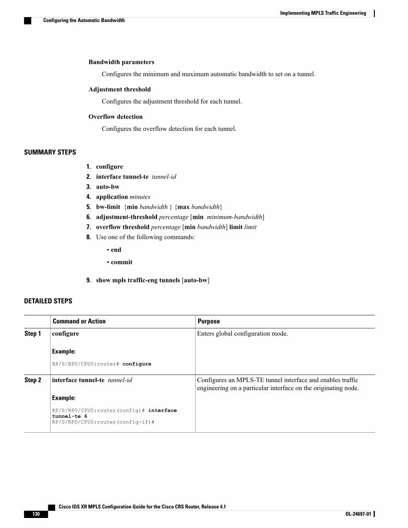
Bandwidth parameters
Configures the minimum and maximum automatic bandwidth to set on a tunnel.
Adjustment threshold
Configures the adjustment threshold for each tunnel.
Overflow detection
Configures the overflow detection for each tunnel.
SUMMARY STEPS
1. configure2. interface tunnel-te tunnel-id3. auto-bw4. application minutes5. bw-limit {min bandwidth } {max bandwidth}6. adjustment-threshold percentage [min minimum-bandwidth]7. overflow threshold percentage [min bandwidth] limit limit8. Use one of the following commands:
• end
• commit
9. show mpls traffic-eng tunnels [auto-bw]
DETAILED STEPS
PurposeCommand or Action
Enters global configuration mode.configure
Example:
RP/0/RP0/CPU0:router# configure
Step 1
Configures an MPLS-TE tunnel interface and enables trafficengineering on a particular interface on the originating node.
interface tunnel-te tunnel-id
Example:
RP/0/RP0/CPU0:router(config)# interface
Step 2
tunnel-te 6RP/0/RP0/CPU0:router(config-if)#
Cisco IOS XR MPLS Configuration Guide for the Cisco CRS Router, Release 4.1130 OL-24697-01
Implementing MPLS Traffic EngineeringConfiguring the Automatic Bandwidth
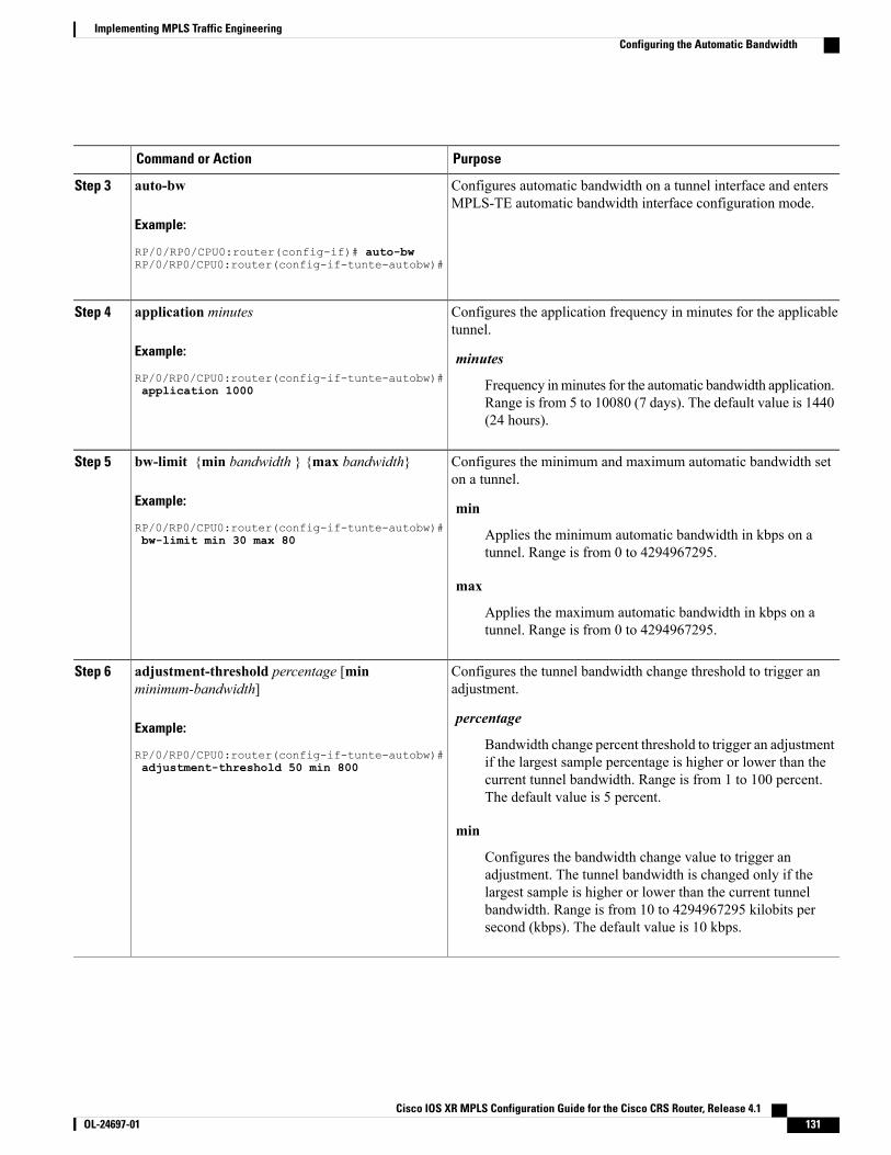
PurposeCommand or Action
Configures automatic bandwidth on a tunnel interface and entersMPLS-TE automatic bandwidth interface configuration mode.
auto-bw
Example:
RP/0/RP0/CPU0:router(config-if)# auto-bw
Step 3
RP/0/RP0/CPU0:router(config-if-tunte-autobw)#
Configures the application frequency in minutes for the applicabletunnel.
application minutes
Example:
RP/0/RP0/CPU0:router(config-if-tunte-autobw)#
Step 4
minutes
Frequency inminutes for the automatic bandwidth application.Range is from 5 to 10080 (7 days). The default value is 1440(24 hours).
application 1000
Configures the minimum and maximum automatic bandwidth seton a tunnel.
bw-limit {min bandwidth } {max bandwidth}
Example:
RP/0/RP0/CPU0:router(config-if-tunte-autobw)#
Step 5
min
Applies the minimum automatic bandwidth in kbps on atunnel. Range is from 0 to 4294967295.
bw-limit min 30 max 80
max
Applies the maximum automatic bandwidth in kbps on atunnel. Range is from 0 to 4294967295.
Configures the tunnel bandwidth change threshold to trigger anadjustment.
adjustment-threshold percentage [minminimum-bandwidth]
Example:
RP/0/RP0/CPU0:router(config-if-tunte-autobw)#
Step 6
percentage
Bandwidth change percent threshold to trigger an adjustmentif the largest sample percentage is higher or lower than thecurrent tunnel bandwidth. Range is from 1 to 100 percent.The default value is 5 percent.
adjustment-threshold 50 min 800
min
Configures the bandwidth change value to trigger anadjustment. The tunnel bandwidth is changed only if thelargest sample is higher or lower than the current tunnelbandwidth. Range is from 10 to 4294967295 kilobits persecond (kbps). The default value is 10 kbps.
Cisco IOS XR MPLS Configuration Guide for the Cisco CRS Router, Release 4.1 OL-24697-01 131
Implementing MPLS Traffic EngineeringConfiguring the Automatic Bandwidth
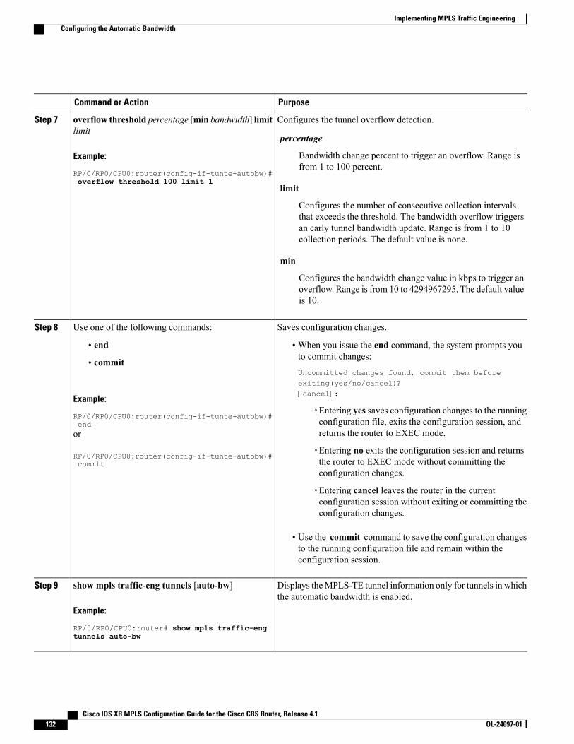
PurposeCommand or Action
Configures the tunnel overflow detection.overflow threshold percentage [min bandwidth] limitlimit
Step 7
percentage
Example:
RP/0/RP0/CPU0:router(config-if-tunte-autobw)#
Bandwidth change percent to trigger an overflow. Range isfrom 1 to 100 percent.
overflow threshold 100 limit 1limit
Configures the number of consecutive collection intervalsthat exceeds the threshold. The bandwidth overflow triggersan early tunnel bandwidth update. Range is from 1 to 10collection periods. The default value is none.
min
Configures the bandwidth change value in kbps to trigger anoverflow. Range is from 10 to 4294967295. The default valueis 10.
Saves configuration changes.Use one of the following commands:Step 8
• end •When you issue the end command, the system prompts youto commit changes:
Uncommitted changes found, commit them beforeexiting(yes/no/cancel)?[cancel]:
• commit
Example:
RP/0/RP0/CPU0:router(config-if-tunte-autobw)#end
◦Entering yes saves configuration changes to the runningconfiguration file, exits the configuration session, andreturns the router to EXEC mode.or
RP/0/RP0/CPU0:router(config-if-tunte-autobw)#commit
◦Entering no exits the configuration session and returnsthe router to EXEC mode without committing theconfiguration changes.
◦Entering cancel leaves the router in the currentconfiguration session without exiting or committing theconfiguration changes.
• Use the commit command to save the configuration changesto the running configuration file and remain within theconfiguration session.
Displays theMPLS-TE tunnel information only for tunnels in whichthe automatic bandwidth is enabled.
show mpls traffic-eng tunnels [auto-bw]
Example:
RP/0/RP0/CPU0:router# show mpls traffic-eng
Step 9
tunnels auto-bw
Cisco IOS XR MPLS Configuration Guide for the Cisco CRS Router, Release 4.1132 OL-24697-01
Implementing MPLS Traffic EngineeringConfiguring the Automatic Bandwidth
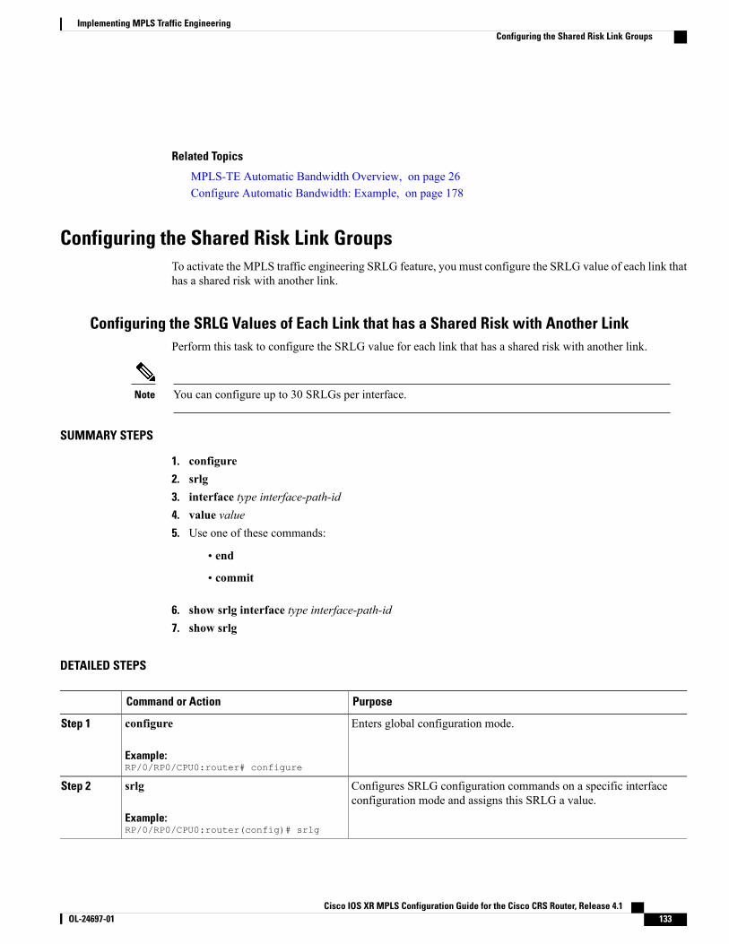
Related Topics
MPLS-TE Automatic Bandwidth Overview, on page 26Configure Automatic Bandwidth: Example, on page 178
Configuring the Shared Risk Link GroupsTo activate the MPLS traffic engineering SRLG feature, you must configure the SRLG value of each link thathas a shared risk with another link.
Configuring the SRLG Values of Each Link that has a Shared Risk with Another LinkPerform this task to configure the SRLG value for each link that has a shared risk with another link.
You can configure up to 30 SRLGs per interface.Note
SUMMARY STEPS
1. configure2. srlg3. interface type interface-path-id4. value value5. Use one of these commands:
• end
• commit
6. show srlg interface type interface-path-id7. show srlg
DETAILED STEPS
PurposeCommand or Action
Enters global configuration mode.configure
Example:RP/0/RP0/CPU0:router# configure
Step 1
Configures SRLG configuration commands on a specific interfaceconfiguration mode and assigns this SRLG a value.
srlg
Example:RP/0/RP0/CPU0:router(config)# srlg
Step 2
Cisco IOS XR MPLS Configuration Guide for the Cisco CRS Router, Release 4.1 OL-24697-01 133
Implementing MPLS Traffic EngineeringConfiguring the Shared Risk Link Groups
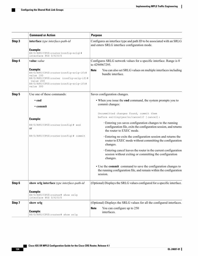
PurposeCommand or Action
Configures an interface type and path ID to be associated with an SRLGand enters SRLG interface configuration mode.
interface type interface-path-id
Example:RP/0/RP0/CPU0:router(config-srlg)#interface POS 0/6/0/0
Step 3
Configures SRLG network values for a specific interface. Range is 0to 4294967295.
value value
Example:RP/0/RP0/CPU0:router(config-srlg-if)#value 100
Step 4
You can also set SRLG values on multiple interfaces includingbundle interface.
Note
RP/0/RP0/CPU0:router (config-srlg-if)#value 200RP/0/RP0/CPU0:router(config-srlg-if)#value 300
Saves configuration changes.Use one of these commands:Step 5
• end •When you issue the end command, the system prompts you tocommit changes:
Uncommitted changes found, commit thembefore exiting(yes/no/cancel)? [cancel]:
• commit
Example:
RP/0/RP0/CPU0:router(config)# end◦Entering yes saves configuration changes to the runningconfiguration file, exits the configuration session, and returnsthe router to EXEC mode.
or
RP/0/RP0/CPU0:router(config)# commit ◦Entering no exits the configuration session and returns therouter to EXECmode without committing the configurationchanges.
◦Entering cancel leaves the router in the current configurationsession without exiting or committing the configurationchanges.
• Use the commit command to save the configuration changes tothe running configuration file, and remain within the configurationsession.
(Optional) Displays the SRLG values configured for a specific interface.show srlg interface type interface-path-id
Example:RP/0/RP0/CPU0:router# show srlginterface POS 0/6/0/0
Step 6
(Optional) Displays the SRLG values for all the configured interfaces.show srlgStep 7
Example:RP/0/RP0/CPU0:router# show srlg
You can configure up to 250interfaces.
Note
Cisco IOS XR MPLS Configuration Guide for the Cisco CRS Router, Release 4.1134 OL-24697-01
Implementing MPLS Traffic EngineeringConfiguring the Shared Risk Link Groups
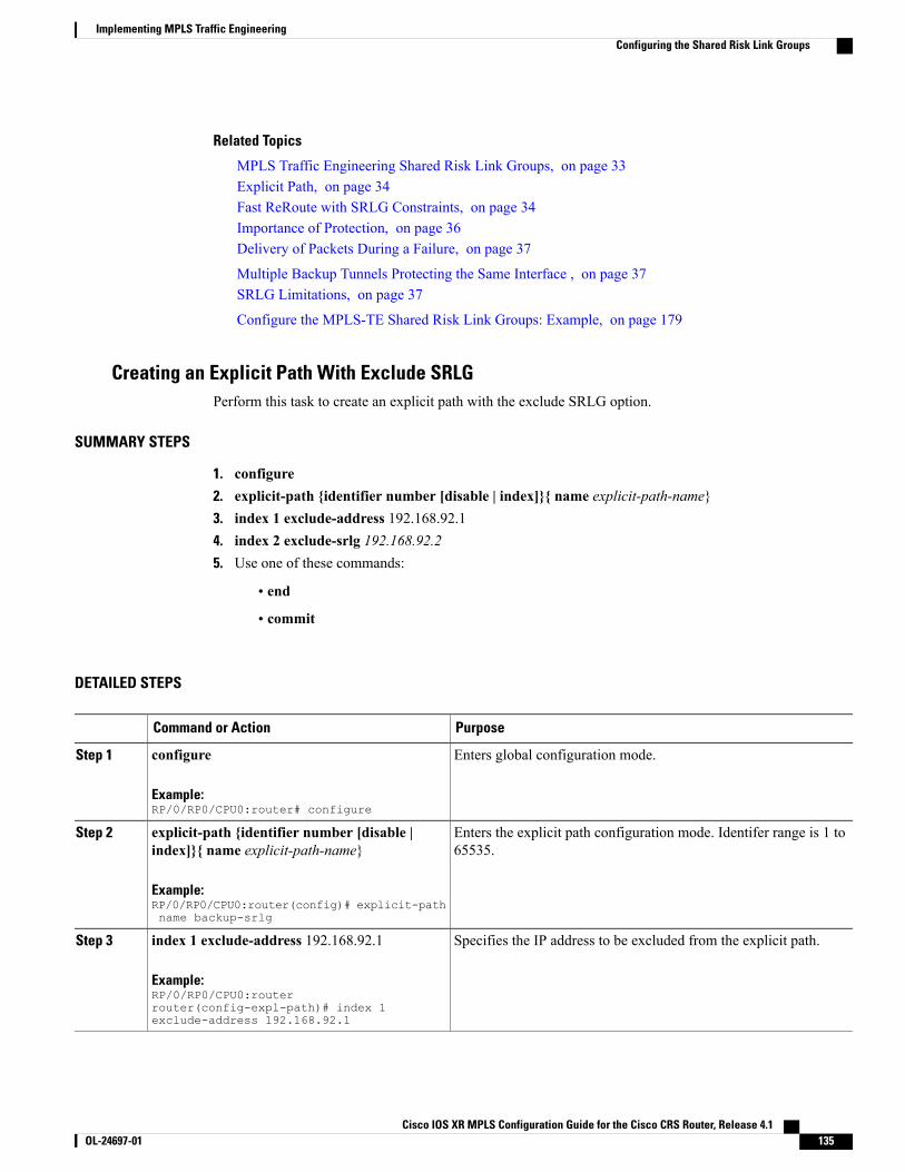
Related Topics
MPLS Traffic Engineering Shared Risk Link Groups, on page 33Explicit Path, on page 34Fast ReRoute with SRLG Constraints, on page 34Importance of Protection, on page 36Delivery of Packets During a Failure, on page 37
Multiple Backup Tunnels Protecting the Same Interface , on page 37SRLG Limitations, on page 37
Configure the MPLS-TE Shared Risk Link Groups: Example, on page 179
Creating an Explicit Path With Exclude SRLGPerform this task to create an explicit path with the exclude SRLG option.
SUMMARY STEPS
1. configure2. explicit-path {identifier number [disable | index]}{ name explicit-path-name}3. index 1 exclude-address 192.168.92.14. index 2 exclude-srlg 192.168.92.25. Use one of these commands:
• end
• commit
DETAILED STEPS
PurposeCommand or Action
Enters global configuration mode.configure
Example:RP/0/RP0/CPU0:router# configure
Step 1
Enters the explicit path configuration mode. Identifer range is 1 to65535.
explicit-path {identifier number [disable |index]}{ name explicit-path-name}
Example:RP/0/RP0/CPU0:router(config)# explicit-pathname backup-srlg
Step 2
Specifies the IP address to be excluded from the explicit path.index 1 exclude-address 192.168.92.1
Example:RP/0/RP0/CPU0:routerrouter(config-expl-path)# index 1exclude-address 192.168.92.1
Step 3
Cisco IOS XR MPLS Configuration Guide for the Cisco CRS Router, Release 4.1 OL-24697-01 135
Implementing MPLS Traffic EngineeringConfiguring the Shared Risk Link Groups
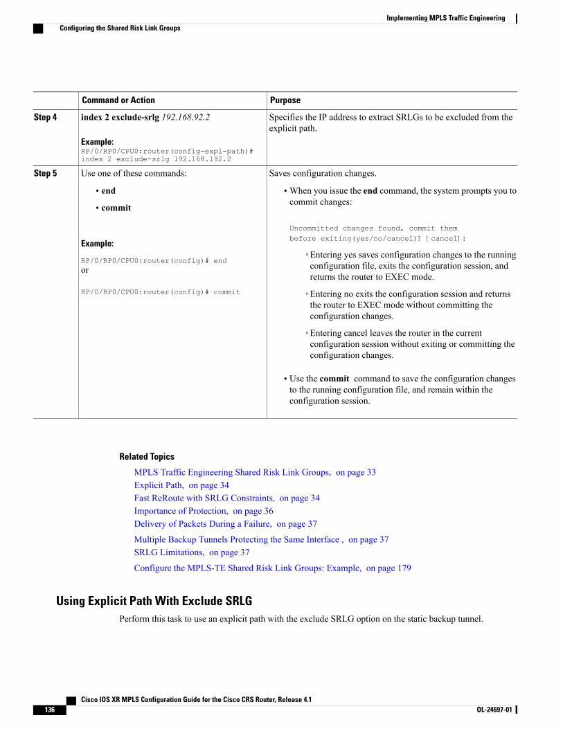
PurposeCommand or Action
Specifies the IP address to extract SRLGs to be excluded from theexplicit path.
index 2 exclude-srlg 192.168.92.2
Example:RP/0/RP0/CPU0:router(config-expl-path)#index 2 exclude-srlg 192.168.192.2
Step 4
Saves configuration changes.Use one of these commands:Step 5
• end •When you issue the end command, the system prompts you tocommit changes:
Uncommitted changes found, commit thembefore exiting(yes/no/cancel)? [cancel]:
• commit
Example:
RP/0/RP0/CPU0:router(config)# end◦Entering yes saves configuration changes to the runningconfiguration file, exits the configuration session, andreturns the router to EXEC mode.
or
RP/0/RP0/CPU0:router(config)# commit ◦Entering no exits the configuration session and returnsthe router to EXEC mode without committing theconfiguration changes.
◦Entering cancel leaves the router in the currentconfiguration session without exiting or committing theconfiguration changes.
• Use the commit command to save the configuration changesto the running configuration file, and remain within theconfiguration session.
Related Topics
MPLS Traffic Engineering Shared Risk Link Groups, on page 33Explicit Path, on page 34Fast ReRoute with SRLG Constraints, on page 34Importance of Protection, on page 36Delivery of Packets During a Failure, on page 37
Multiple Backup Tunnels Protecting the Same Interface , on page 37SRLG Limitations, on page 37
Configure the MPLS-TE Shared Risk Link Groups: Example, on page 179
Using Explicit Path With Exclude SRLGPerform this task to use an explicit path with the exclude SRLG option on the static backup tunnel.
Cisco IOS XR MPLS Configuration Guide for the Cisco CRS Router, Release 4.1136 OL-24697-01
Implementing MPLS Traffic EngineeringConfiguring the Shared Risk Link Groups
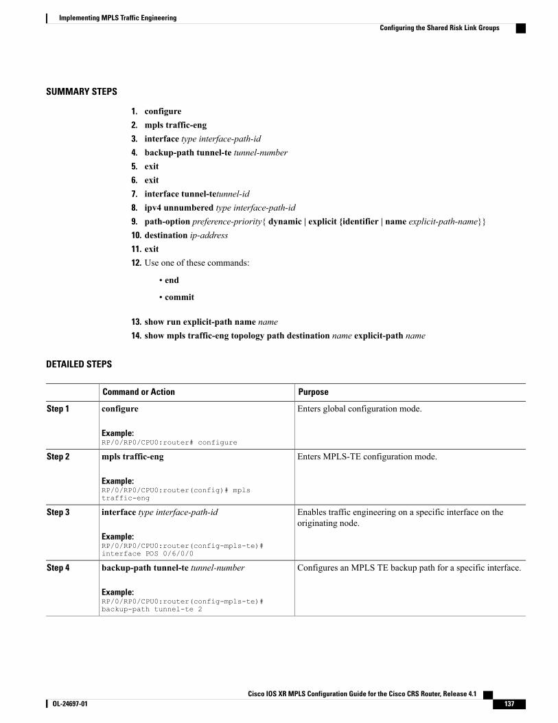
SUMMARY STEPS
1. configure2. mpls traffic-eng3. interface type interface-path-id4. backup-path tunnel-te tunnel-number5. exit6. exit7. interface tunnel-tetunnel-id8. ipv4 unnumbered type interface-path-id9. path-option preference-priority{ dynamic | explicit {identifier | name explicit-path-name}}10. destination ip-address11. exit12. Use one of these commands:
• end
• commit
13. show run explicit-path name name14. show mpls traffic-eng topology path destination name explicit-path name
DETAILED STEPS
PurposeCommand or Action
Enters global configuration mode.configure
Example:RP/0/RP0/CPU0:router# configure
Step 1
Enters MPLS-TE configuration mode.mpls traffic-eng
Example:RP/0/RP0/CPU0:router(config)# mplstraffic-eng
Step 2
Enables traffic engineering on a specific interface on theoriginating node.
interface type interface-path-id
Example:RP/0/RP0/CPU0:router(config-mpls-te)#interface POS 0/6/0/0
Step 3
Configures an MPLS TE backup path for a specific interface.backup-path tunnel-te tunnel-number
Example:RP/0/RP0/CPU0:router(config-mpls-te)#backup-path tunnel-te 2
Step 4
Cisco IOS XR MPLS Configuration Guide for the Cisco CRS Router, Release 4.1 OL-24697-01 137
Implementing MPLS Traffic EngineeringConfiguring the Shared Risk Link Groups
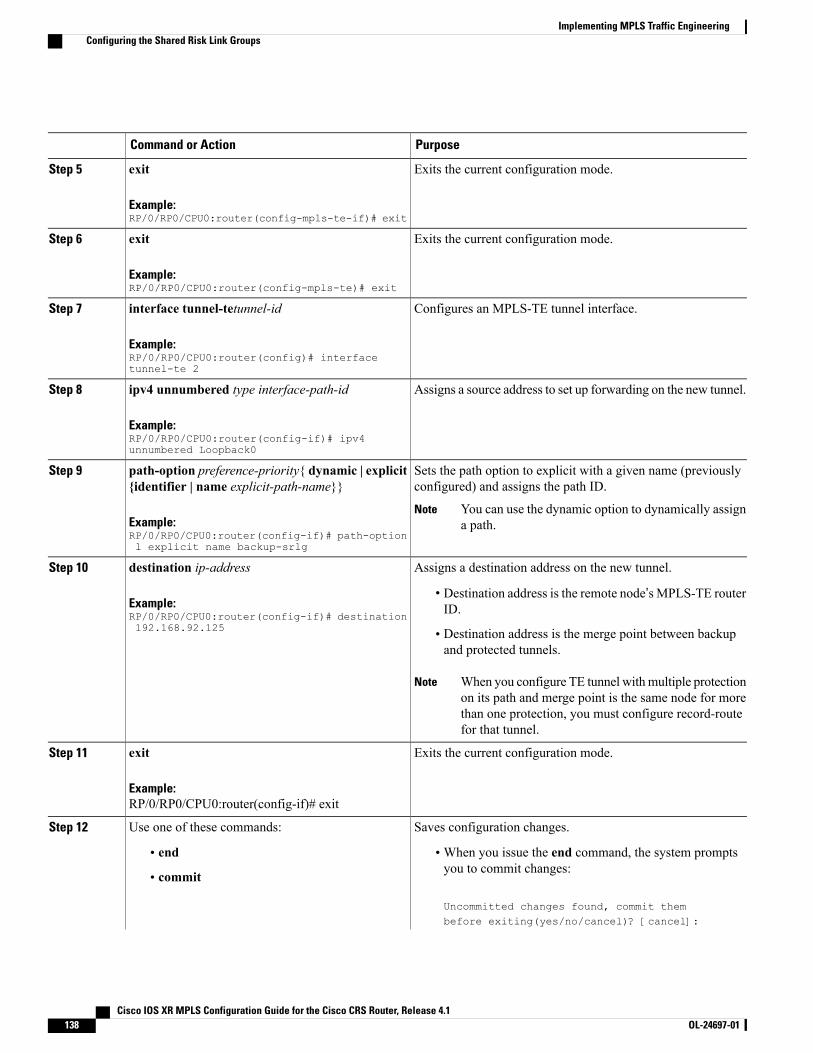
PurposeCommand or Action
Exits the current configuration mode.exit
Example:RP/0/RP0/CPU0:router(config-mpls-te-if)# exit
Step 5
Exits the current configuration mode.exit
Example:RP/0/RP0/CPU0:router(config-mpls-te)# exit
Step 6
Configures an MPLS-TE tunnel interface.interface tunnel-tetunnel-id
Example:RP/0/RP0/CPU0:router(config)# interfacetunnel-te 2
Step 7
Assigns a source address to set up forwarding on the new tunnel.ipv4 unnumbered type interface-path-id
Example:RP/0/RP0/CPU0:router(config-if)# ipv4unnumbered Loopback0
Step 8
Sets the path option to explicit with a given name (previouslyconfigured) and assigns the path ID.
path-option preference-priority{ dynamic | explicit{identifier | name explicit-path-name}}
Step 9
Example:RP/0/RP0/CPU0:router(config-if)# path-optionl explicit name backup-srlg
You can use the dynamic option to dynamically assigna path.
Note
Assigns a destination address on the new tunnel.destination ip-addressStep 10
Example:RP/0/RP0/CPU0:router(config-if)# destination192.168.92.125
• Destination address is the remote node’s MPLS-TE routerID.
• Destination address is the merge point between backupand protected tunnels.
When you configure TE tunnel withmultiple protectionon its path and merge point is the same node for morethan one protection, you must configure record-routefor that tunnel.
Note
Exits the current configuration mode.exit
Example:
Step 11
RP/0/RP0/CPU0:router(config-if)# exit
Saves configuration changes.Use one of these commands:Step 12
• end •When you issue the end command, the system promptsyou to commit changes:
Uncommitted changes found, commit thembefore exiting(yes/no/cancel)? [cancel]:
• commit
Cisco IOS XR MPLS Configuration Guide for the Cisco CRS Router, Release 4.1138 OL-24697-01
Implementing MPLS Traffic EngineeringConfiguring the Shared Risk Link Groups
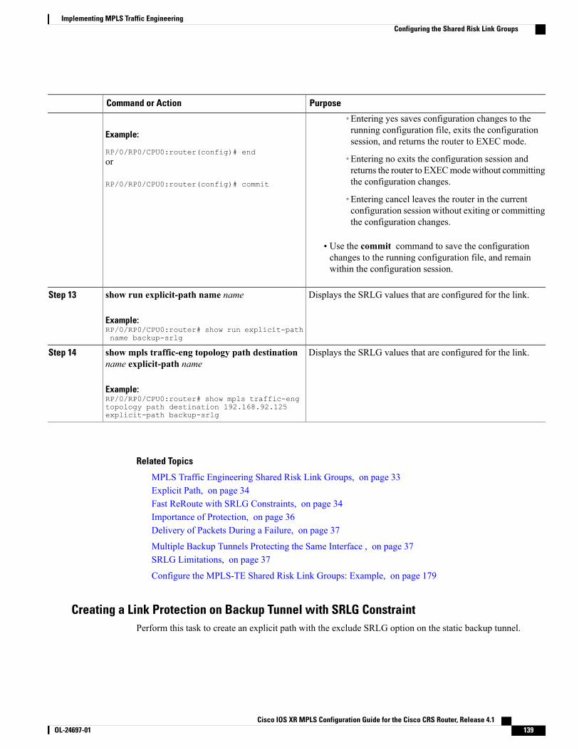
PurposeCommand or Action
Example:
RP/0/RP0/CPU0:router(config)# end
◦Entering yes saves configuration changes to therunning configuration file, exits the configurationsession, and returns the router to EXEC mode.
◦Entering no exits the configuration session andreturns the router to EXECmodewithout committingthe configuration changes.
or
RP/0/RP0/CPU0:router(config)# commit
◦Entering cancel leaves the router in the currentconfiguration session without exiting or committingthe configuration changes.
• Use the commit command to save the configurationchanges to the running configuration file, and remainwithin the configuration session.
Displays the SRLG values that are configured for the link.show run explicit-path name name
Example:RP/0/RP0/CPU0:router# show run explicit-pathname backup-srlg
Step 13
Displays the SRLG values that are configured for the link.show mpls traffic-eng topology path destinationname explicit-path name
Step 14
Example:RP/0/RP0/CPU0:router# show mpls traffic-engtopology path destination 192.168.92.125explicit-path backup-srlg
Related Topics
MPLS Traffic Engineering Shared Risk Link Groups, on page 33Explicit Path, on page 34Fast ReRoute with SRLG Constraints, on page 34Importance of Protection, on page 36Delivery of Packets During a Failure, on page 37
Multiple Backup Tunnels Protecting the Same Interface , on page 37SRLG Limitations, on page 37
Configure the MPLS-TE Shared Risk Link Groups: Example, on page 179
Creating a Link Protection on Backup Tunnel with SRLG ConstraintPerform this task to create an explicit path with the exclude SRLG option on the static backup tunnel.
Cisco IOS XR MPLS Configuration Guide for the Cisco CRS Router, Release 4.1 OL-24697-01 139
Implementing MPLS Traffic EngineeringConfiguring the Shared Risk Link Groups
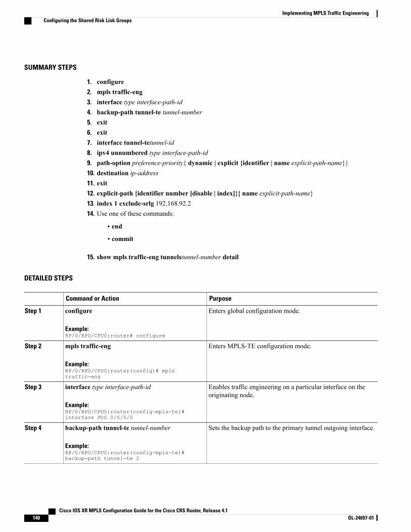
SUMMARY STEPS
1. configure2. mpls traffic-eng3. interface type interface-path-id4. backup-path tunnel-te tunnel-number5. exit6. exit7. interface tunnel-tetunnel-id8. ipv4 unnumbered type interface-path-id9. path-option preference-priority{ dynamic | explicit {identifier | name explicit-path-name}}10. destination ip-address11. exit12. explicit-path {identifier number [disable | index]}{ name explicit-path-name}13. index 1 exclude-srlg 192.168.92.214. Use one of these commands:
• end
• commit
15. show mpls traffic-eng tunnelstunnel-number detail
DETAILED STEPS
PurposeCommand or Action
Enters global configuration mode.configure
Example:RP/0/RP0/CPU0:router# configure
Step 1
Enters MPLS-TE configuration mode.mpls traffic-eng
Example:RP/0/RP0/CPU0:router(config)# mplstraffic-eng
Step 2
Enables traffic engineering on a particular interface on theoriginating node.
interface type interface-path-id
Example:RP/0/RP0/CPU0:router(config-mpls-te)#interface POS 0/6/0/0
Step 3
Sets the backup path to the primary tunnel outgoing interface.backup-path tunnel-te tunnel-number
Example:RP/0/RP0/CPU0:router(config-mpls-te)#backup-path tunnel-te 2
Step 4
Cisco IOS XR MPLS Configuration Guide for the Cisco CRS Router, Release 4.1140 OL-24697-01
Implementing MPLS Traffic EngineeringConfiguring the Shared Risk Link Groups
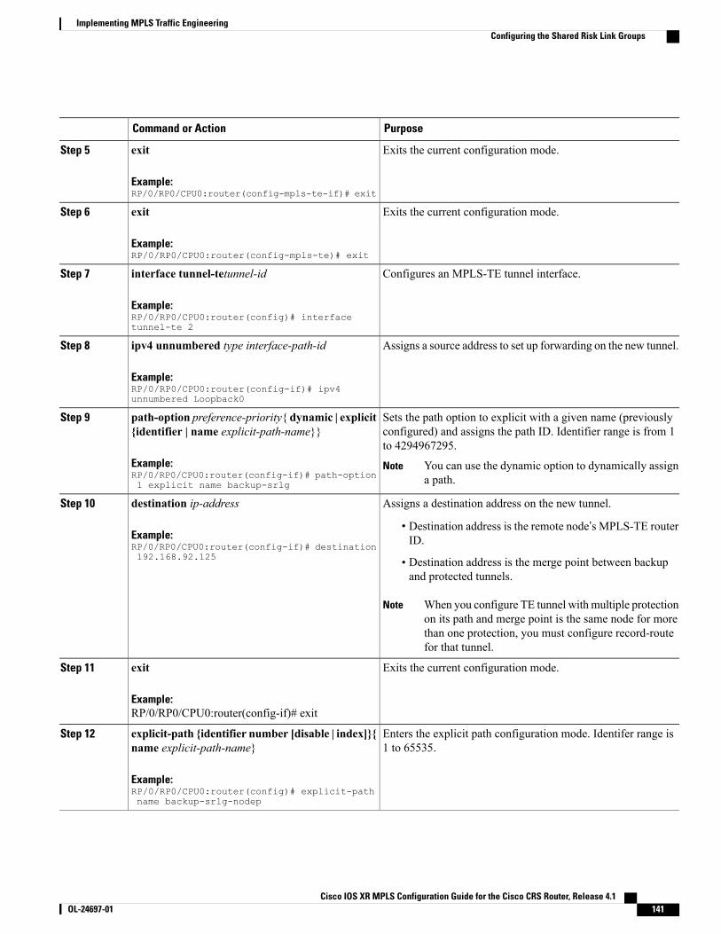
PurposeCommand or Action
Exits the current configuration mode.exit
Example:RP/0/RP0/CPU0:router(config-mpls-te-if)# exit
Step 5
Exits the current configuration mode.exit
Example:RP/0/RP0/CPU0:router(config-mpls-te)# exit
Step 6
Configures an MPLS-TE tunnel interface.interface tunnel-tetunnel-id
Example:RP/0/RP0/CPU0:router(config)# interfacetunnel-te 2
Step 7
Assigns a source address to set up forwarding on the new tunnel.ipv4 unnumbered type interface-path-id
Example:RP/0/RP0/CPU0:router(config-if)# ipv4unnumbered Loopback0
Step 8
Sets the path option to explicit with a given name (previouslyconfigured) and assigns the path ID. Identifier range is from 1to 4294967295.
path-option preference-priority{ dynamic | explicit{identifier | name explicit-path-name}}
Example:RP/0/RP0/CPU0:router(config-if)# path-option1 explicit name backup-srlg
Step 9
You can use the dynamic option to dynamically assigna path.
Note
Assigns a destination address on the new tunnel.destination ip-addressStep 10
Example:RP/0/RP0/CPU0:router(config-if)# destination192.168.92.125
• Destination address is the remote node’s MPLS-TE routerID.
• Destination address is the merge point between backupand protected tunnels.
When you configure TE tunnel with multiple protectionon its path and merge point is the same node for morethan one protection, you must configure record-routefor that tunnel.
Note
Exits the current configuration mode.exit
Example:
Step 11
RP/0/RP0/CPU0:router(config-if)# exit
Enters the explicit path configuration mode. Identifer range is1 to 65535.
explicit-path {identifier number [disable | index]}{name explicit-path-name}
Example:RP/0/RP0/CPU0:router(config)# explicit-pathname backup-srlg-nodep
Step 12
Cisco IOS XR MPLS Configuration Guide for the Cisco CRS Router, Release 4.1 OL-24697-01 141
Implementing MPLS Traffic EngineeringConfiguring the Shared Risk Link Groups
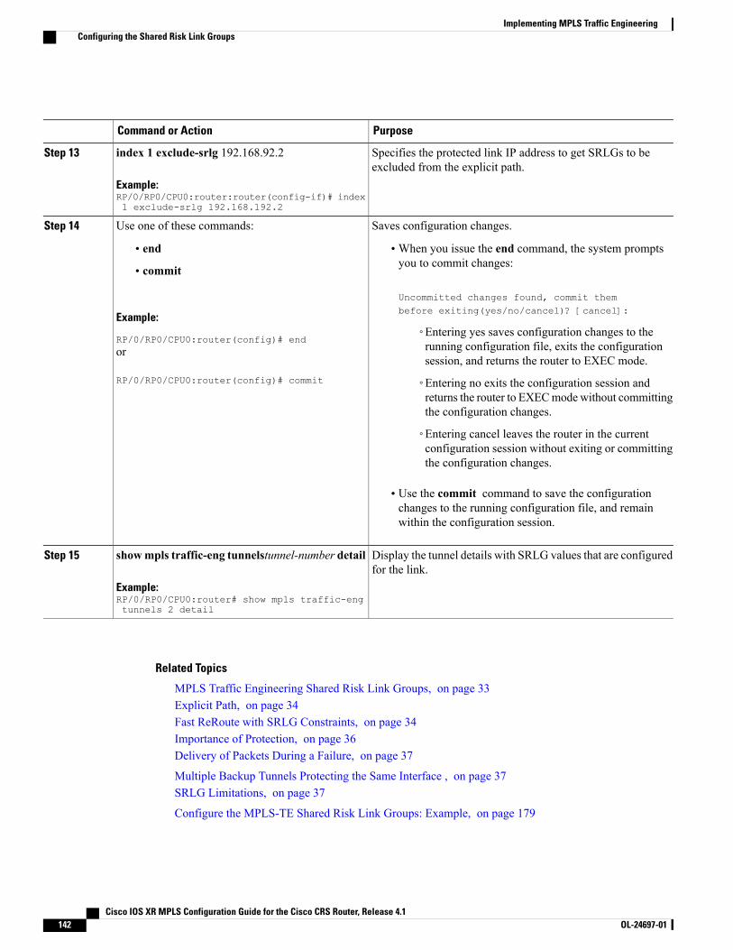
PurposeCommand or Action
Specifies the protected link IP address to get SRLGs to beexcluded from the explicit path.
index 1 exclude-srlg 192.168.92.2
Example:RP/0/RP0/CPU0:router:router(config-if)# index1 exclude-srlg 192.168.192.2
Step 13
Saves configuration changes.Use one of these commands:Step 14
• end •When you issue the end command, the system promptsyou to commit changes:
Uncommitted changes found, commit thembefore exiting(yes/no/cancel)? [cancel]:
• commit
Example:
RP/0/RP0/CPU0:router(config)# end◦Entering yes saves configuration changes to therunning configuration file, exits the configurationsession, and returns the router to EXEC mode.
or
RP/0/RP0/CPU0:router(config)# commit ◦Entering no exits the configuration session andreturns the router to EXECmodewithout committingthe configuration changes.
◦Entering cancel leaves the router in the currentconfiguration session without exiting or committingthe configuration changes.
• Use the commit command to save the configurationchanges to the running configuration file, and remainwithin the configuration session.
Display the tunnel details with SRLG values that are configuredfor the link.
showmpls traffic-eng tunnelstunnel-number detail
Example:RP/0/RP0/CPU0:router# show mpls traffic-engtunnels 2 detail
Step 15
Related Topics
MPLS Traffic Engineering Shared Risk Link Groups, on page 33Explicit Path, on page 34Fast ReRoute with SRLG Constraints, on page 34Importance of Protection, on page 36Delivery of Packets During a Failure, on page 37
Multiple Backup Tunnels Protecting the Same Interface , on page 37SRLG Limitations, on page 37
Configure the MPLS-TE Shared Risk Link Groups: Example, on page 179
Cisco IOS XR MPLS Configuration Guide for the Cisco CRS Router, Release 4.1142 OL-24697-01
Implementing MPLS Traffic EngineeringConfiguring the Shared Risk Link Groups
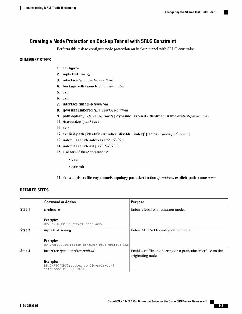
Creating a Node Protection on Backup Tunnel with SRLG ConstraintPerform this task to configure node protection on backup tunnel with SRLG constraint.
SUMMARY STEPS
1. configure2. mpls traffic-eng3. interface type interface-path-id4. backup-path tunnel-te tunnel-number5. exit6. exit7. interface tunnel-tetunnel-id8. ipv4 unnumbered type interface-path-id9. path-option preference-priority{ dynamic | explicit {identifier | name explicit-path-name}}10. destination ip-address11. exit12. explicit-path {identifier number [disable | index]}{ name explicit-path-name}13. index 1 exclude-address 192.168.92.114. index 2 exclude-srlg 192.168.92.215. Use one of these commands:
• end
• commit
16. show mpls traffic-eng tunnels topology path destination ip-address explicit-path-name name
DETAILED STEPS
PurposeCommand or Action
Enters global configuration mode.configure
Example:RP/0/RP0/CPU0:router# configure
Step 1
Enters MPLS-TE configuration mode.mpls traffic-eng
Example:RP/0/RP0/CPU0:router(config)# mpls traffic-eng
Step 2
Enables traffic engineering on a particular interface on theoriginating node.
interface type interface-path-id
Example:RP/0/RP0/CPU0:router(config-mpls-te)#interface POS 0/6/0/0
Step 3
Cisco IOS XR MPLS Configuration Guide for the Cisco CRS Router, Release 4.1 OL-24697-01 143
Implementing MPLS Traffic EngineeringConfiguring the Shared Risk Link Groups
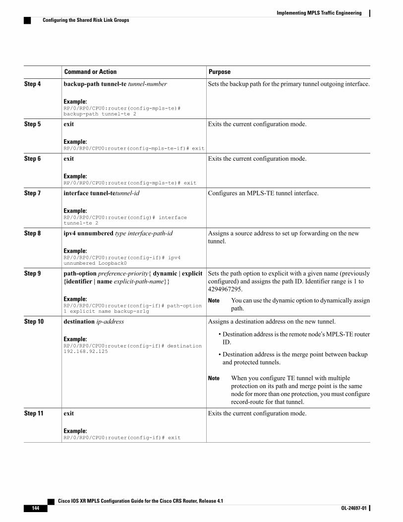
PurposeCommand or Action
Sets the backup path for the primary tunnel outgoing interface.backup-path tunnel-te tunnel-number
Example:RP/0/RP0/CPU0:router(config-mpls-te)#backup-path tunnel-te 2
Step 4
Exits the current configuration mode.exit
Example:RP/0/RP0/CPU0:router(config-mpls-te-if)# exit
Step 5
Exits the current configuration mode.exit
Example:RP/0/RP0/CPU0:router(config-mpls-te)# exit
Step 6
Configures an MPLS-TE tunnel interface.interface tunnel-tetunnel-id
Example:RP/0/RP0/CPU0:router(config)# interfacetunnel-te 2
Step 7
Assigns a source address to set up forwarding on the newtunnel.
ipv4 unnumbered type interface-path-id
Example:RP/0/RP0/CPU0:router(config-if)# ipv4unnumbered Loopback0
Step 8
Sets the path option to explicit with a given name (previouslyconfigured) and assigns the path ID. Identifier range is 1 to4294967295.
path-option preference-priority{ dynamic | explicit{identifier | name explicit-path-name}}
Example:RP/0/RP0/CPU0:router(config-if)# path-option1 explicit name backup-srlg
Step 9
You can use the dynamic option to dynamically assignpath.
Note
Assigns a destination address on the new tunnel.destination ip-addressStep 10
Example:RP/0/RP0/CPU0:router(config-if)# destination192.168.92.125
• Destination address is the remote node’sMPLS-TE routerID.
• Destination address is the merge point between backupand protected tunnels.
When you configure TE tunnel with multipleprotection on its path and merge point is the samenode for more than one protection, youmust configurerecord-route for that tunnel.
Note
Exits the current configuration mode.exit
Example:RP/0/RP0/CPU0:router(config-if)# exit
Step 11
Cisco IOS XR MPLS Configuration Guide for the Cisco CRS Router, Release 4.1144 OL-24697-01
Implementing MPLS Traffic EngineeringConfiguring the Shared Risk Link Groups
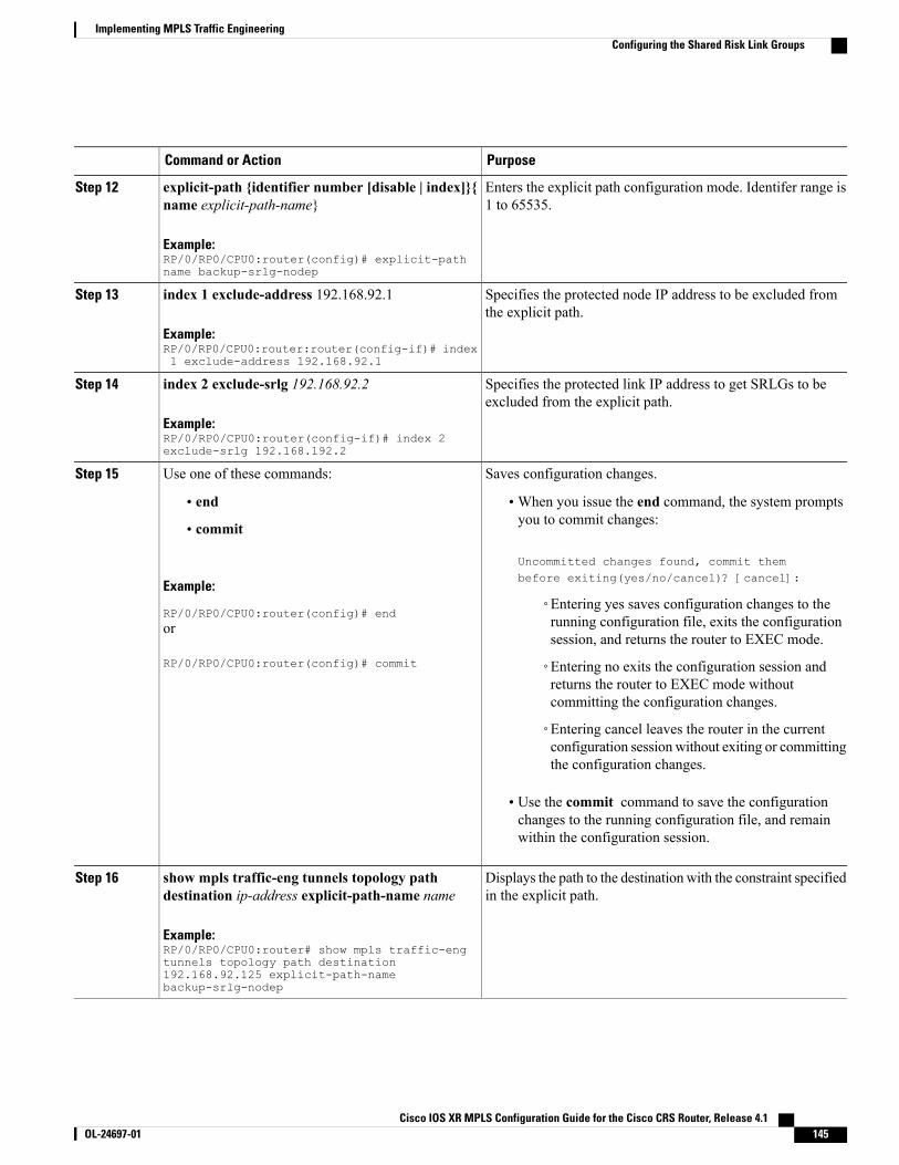
PurposeCommand or Action
Enters the explicit path configuration mode. Identifer range is1 to 65535.
explicit-path {identifier number [disable | index]}{name explicit-path-name}
Example:RP/0/RP0/CPU0:router(config)# explicit-pathname backup-srlg-nodep
Step 12
Specifies the protected node IP address to be excluded fromthe explicit path.
index 1 exclude-address 192.168.92.1
Example:RP/0/RP0/CPU0:router:router(config-if)# index1 exclude-address 192.168.92.1
Step 13
Specifies the protected link IP address to get SRLGs to beexcluded from the explicit path.
index 2 exclude-srlg 192.168.92.2
Example:RP/0/RP0/CPU0:router(config-if)# index 2exclude-srlg 192.168.192.2
Step 14
Saves configuration changes.Use one of these commands:Step 15
• end •When you issue the end command, the system promptsyou to commit changes:
Uncommitted changes found, commit thembefore exiting(yes/no/cancel)? [cancel]:
• commit
Example:
RP/0/RP0/CPU0:router(config)# end◦Entering yes saves configuration changes to therunning configuration file, exits the configurationsession, and returns the router to EXEC mode.
or
RP/0/RP0/CPU0:router(config)# commit ◦Entering no exits the configuration session andreturns the router to EXEC mode withoutcommitting the configuration changes.
◦Entering cancel leaves the router in the currentconfiguration session without exiting or committingthe configuration changes.
• Use the commit command to save the configurationchanges to the running configuration file, and remainwithin the configuration session.
Displays the path to the destination with the constraint specifiedin the explicit path.
show mpls traffic-eng tunnels topology pathdestination ip-address explicit-path-name name
Example:RP/0/RP0/CPU0:router# show mpls traffic-engtunnels topology path destination
Step 16
192.168.92.125 explicit-path-namebackup-srlg-nodep
Cisco IOS XR MPLS Configuration Guide for the Cisco CRS Router, Release 4.1 OL-24697-01 145
Implementing MPLS Traffic EngineeringConfiguring the Shared Risk Link Groups
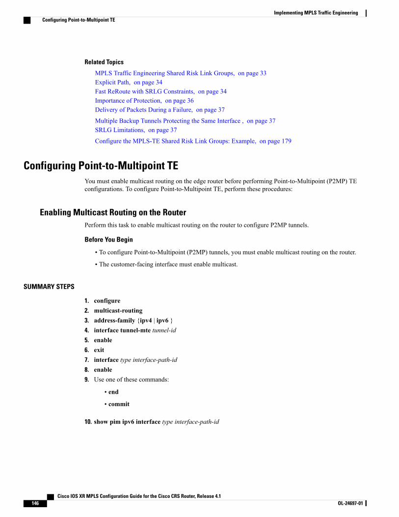
Related Topics
MPLS Traffic Engineering Shared Risk Link Groups, on page 33Explicit Path, on page 34Fast ReRoute with SRLG Constraints, on page 34Importance of Protection, on page 36Delivery of Packets During a Failure, on page 37
Multiple Backup Tunnels Protecting the Same Interface , on page 37SRLG Limitations, on page 37
Configure the MPLS-TE Shared Risk Link Groups: Example, on page 179
Configuring Point-to-Multipoint TEYou must enable multicast routing on the edge router before performing Point-to-Multipoint (P2MP) TEconfigurations. To configure Point-to-Multipoint TE, perform these procedures:
Enabling Multicast Routing on the RouterPerform this task to enable multicast routing on the router to configure P2MP tunnels.
Before You Begin
• To configure Point-to-Multipoint (P2MP) tunnels, you must enable multicast routing on the router.
• The customer-facing interface must enable multicast.
SUMMARY STEPS
1. configure2. multicast-routing3. address-family {ipv4 | ipv6 }4. interface tunnel-mte tunnel-id5. enable6. exit7. interface type interface-path-id8. enable9. Use one of these commands:
• end
• commit
10. show pim ipv6 interface type interface-path-id
Cisco IOS XR MPLS Configuration Guide for the Cisco CRS Router, Release 4.1146 OL-24697-01
Implementing MPLS Traffic EngineeringConfiguring Point-to-Multipoint TE
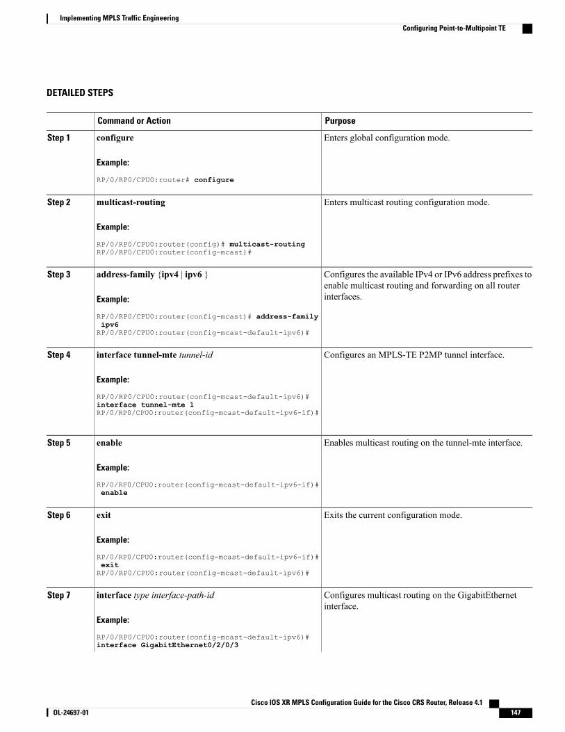
DETAILED STEPS
PurposeCommand or Action
Enters global configuration mode.configure
Example:
RP/0/RP0/CPU0:router# configure
Step 1
Enters multicast routing configuration mode.multicast-routing
Example:
RP/0/RP0/CPU0:router(config)# multicast-routing
Step 2
RP/0/RP0/CPU0:router(config-mcast)#
Configures the available IPv4 or IPv6 address prefixes toenable multicast routing and forwarding on all routerinterfaces.
address-family {ipv4 | ipv6 }
Example:
RP/0/RP0/CPU0:router(config-mcast)# address-family
Step 3
ipv6RP/0/RP0/CPU0:router(config-mcast-default-ipv6)#
Configures an MPLS-TE P2MP tunnel interface.interface tunnel-mte tunnel-id
Example:
RP/0/RP0/CPU0:router(config-mcast-default-ipv6)#
Step 4
interface tunnel-mte 1RP/0/RP0/CPU0:router(config-mcast-default-ipv6-if)#
Enables multicast routing on the tunnel-mte interface.enable
Example:
RP/0/RP0/CPU0:router(config-mcast-default-ipv6-if)#
Step 5
enable
Exits the current configuration mode.exit
Example:
RP/0/RP0/CPU0:router(config-mcast-default-ipv6-if)#
Step 6
exitRP/0/RP0/CPU0:router(config-mcast-default-ipv6)#
Configures multicast routing on the GigabitEthernetinterface.
interface type interface-path-id
Example:
RP/0/RP0/CPU0:router(config-mcast-default-ipv6)#
Step 7
interface GigabitEthernet0/2/0/3
Cisco IOS XR MPLS Configuration Guide for the Cisco CRS Router, Release 4.1 OL-24697-01 147
Implementing MPLS Traffic EngineeringConfiguring Point-to-Multipoint TE
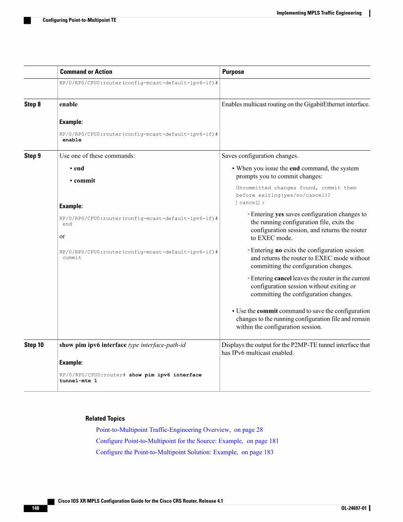
PurposeCommand or Action
RP/0/RP0/CPU0:router(config-mcast-default-ipv6-if)#
Enablesmulticast routing on theGigabitEthernet interface.enable
Example:
RP/0/RP0/CPU0:router(config-mcast-default-ipv6-if)#
Step 8
enable
Saves configuration changes.Use one of these commands:Step 9
• end •When you issue the end command, the systemprompts you to commit changes:
Uncommitted changes found, commit thembefore exiting(yes/no/cancel)?[cancel]:
• commit
Example:
RP/0/RP0/CPU0:router(config-mcast-default-ipv6-if)#◦Entering yes saves configuration changes tothe running configuration file, exits theendconfiguration session, and returns the routerto EXEC mode.or
RP/0/RP0/CPU0:router(config-mcast-default-ipv6-if)# ◦Entering no exits the configuration sessionand returns the router to EXEC mode withoutcommitting the configuration changes.
commit
◦Entering cancel leaves the router in the currentconfiguration session without exiting orcommitting the configuration changes.
• Use the commit command to save the configurationchanges to the running configuration file and remainwithin the configuration session.
Displays the output for the P2MP-TE tunnel interface thathas IPv6 multicast enabled.
show pim ipv6 interface type interface-path-id
Example:
RP/0/RP0/CPU0:router# show pim ipv6 interface
Step 10
tunnel-mte 1
Related Topics
Point-to-Multipoint Traffic-Engineering Overview, on page 28
Configure Point-to-Multipoint for the Source: Example, on page 181
Configure the Point-to-Multipoint Solution: Example, on page 183
Cisco IOS XR MPLS Configuration Guide for the Cisco CRS Router, Release 4.1148 OL-24697-01
Implementing MPLS Traffic EngineeringConfiguring Point-to-Multipoint TE
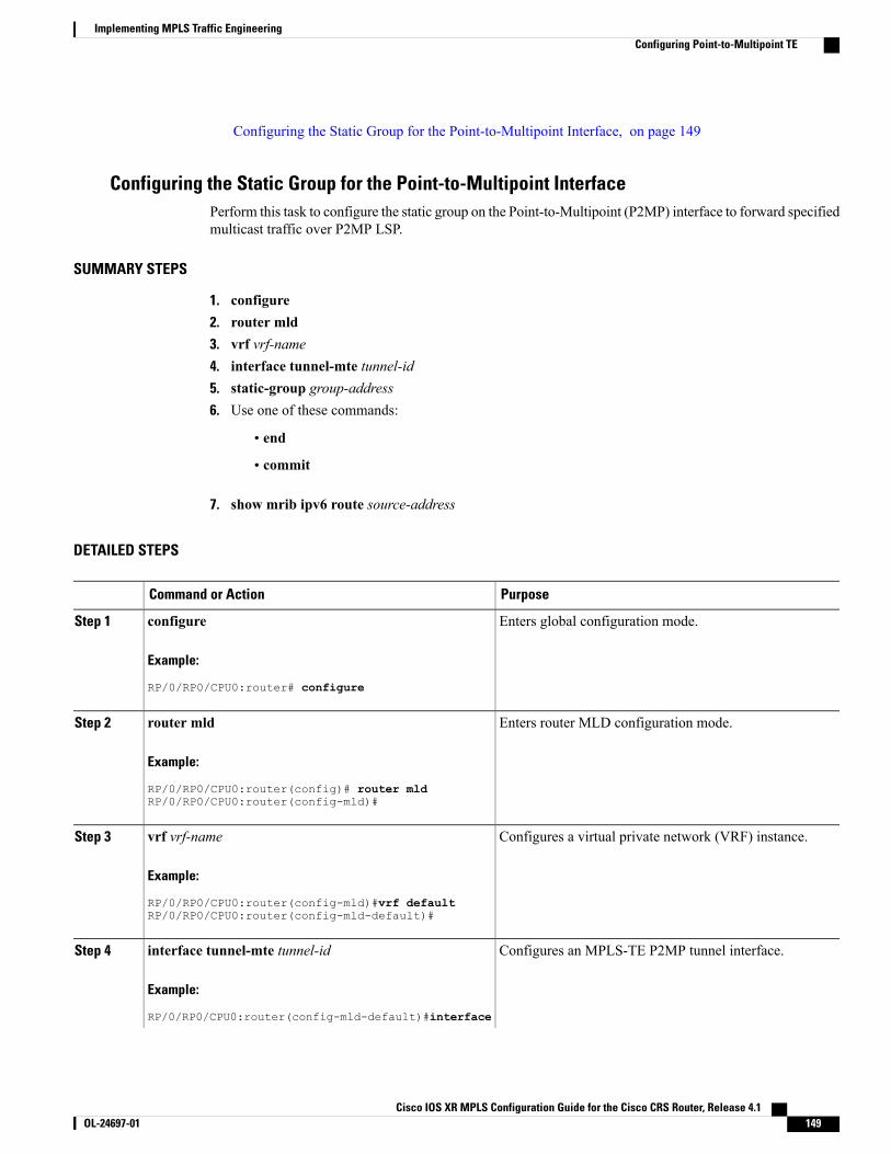
Configuring the Static Group for the Point-to-Multipoint Interface, on page 149
Configuring the Static Group for the Point-to-Multipoint InterfacePerform this task to configure the static group on the Point-to-Multipoint (P2MP) interface to forward specifiedmulticast traffic over P2MP LSP.
SUMMARY STEPS
1. configure2. router mld3. vrf vrf-name4. interface tunnel-mte tunnel-id5. static-group group-address6. Use one of these commands:
• end
• commit
7. show mrib ipv6 route source-address
DETAILED STEPS
PurposeCommand or Action
Enters global configuration mode.configure
Example:
RP/0/RP0/CPU0:router# configure
Step 1
Enters router MLD configuration mode.router mld
Example:
RP/0/RP0/CPU0:router(config)# router mld
Step 2
RP/0/RP0/CPU0:router(config-mld)#
Configures a virtual private network (VRF) instance.vrf vrf-name
Example:
RP/0/RP0/CPU0:router(config-mld)#vrf default
Step 3
RP/0/RP0/CPU0:router(config-mld-default)#
Configures an MPLS-TE P2MP tunnel interface.interface tunnel-mte tunnel-id
Example:
RP/0/RP0/CPU0:router(config-mld-default)#interface
Step 4
Cisco IOS XR MPLS Configuration Guide for the Cisco CRS Router, Release 4.1 OL-24697-01 149
Implementing MPLS Traffic EngineeringConfiguring Point-to-Multipoint TE
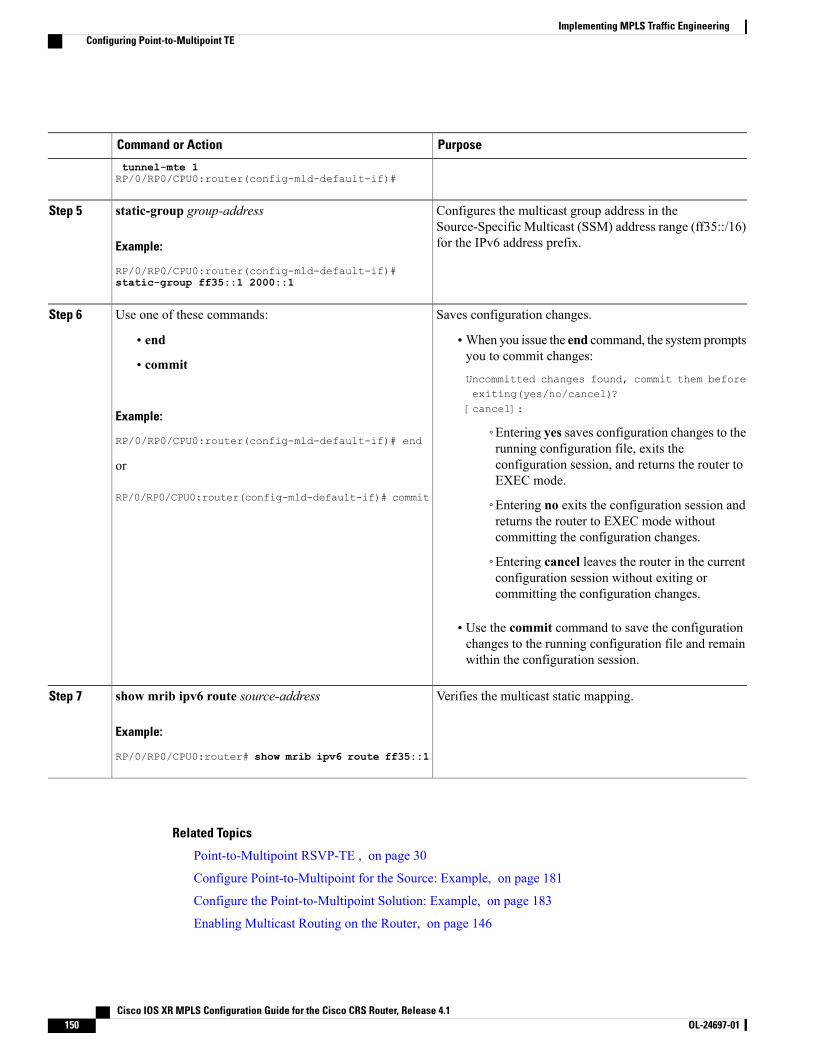
PurposeCommand or Action
tunnel-mte 1RP/0/RP0/CPU0:router(config-mld-default-if)#
Configures the multicast group address in theSource-Specific Multicast (SSM) address range (ff35::/16)for the IPv6 address prefix.
static-group group-address
Example:
RP/0/RP0/CPU0:router(config-mld-default-if)#
Step 5
static-group ff35::1 2000::1
Saves configuration changes.Use one of these commands:Step 6
• end •When you issue the end command, the system promptsyou to commit changes:
Uncommitted changes found, commit them beforeexiting(yes/no/cancel)?[cancel]:
• commit
Example:
RP/0/RP0/CPU0:router(config-mld-default-if)# end◦Entering yes saves configuration changes to therunning configuration file, exits theconfiguration session, and returns the router toEXEC mode.
or
RP/0/RP0/CPU0:router(config-mld-default-if)# commit ◦Entering no exits the configuration session andreturns the router to EXEC mode withoutcommitting the configuration changes.
◦Entering cancel leaves the router in the currentconfiguration session without exiting orcommitting the configuration changes.
• Use the commit command to save the configurationchanges to the running configuration file and remainwithin the configuration session.
Verifies the multicast static mapping.show mrib ipv6 route source-address
Example:
RP/0/RP0/CPU0:router# show mrib ipv6 route ff35::1
Step 7
Related Topics
Point-to-Multipoint RSVP-TE , on page 30
Configure Point-to-Multipoint for the Source: Example, on page 181
Configure the Point-to-Multipoint Solution: Example, on page 183
Enabling Multicast Routing on the Router, on page 146
Cisco IOS XR MPLS Configuration Guide for the Cisco CRS Router, Release 4.1150 OL-24697-01
Implementing MPLS Traffic EngineeringConfiguring Point-to-Multipoint TE
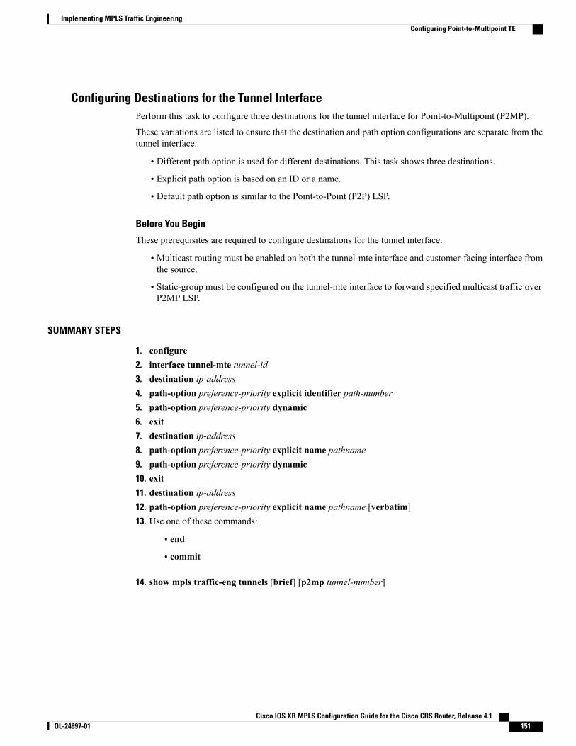
Configuring Destinations for the Tunnel InterfacePerform this task to configure three destinations for the tunnel interface for Point-to-Multipoint (P2MP).
These variations are listed to ensure that the destination and path option configurations are separate from thetunnel interface.
• Different path option is used for different destinations. This task shows three destinations.
• Explicit path option is based on an ID or a name.
• Default path option is similar to the Point-to-Point (P2P) LSP.
Before You Begin
These prerequisites are required to configure destinations for the tunnel interface.
• Multicast routing must be enabled on both the tunnel-mte interface and customer-facing interface fromthe source.
• Static-group must be configured on the tunnel-mte interface to forward specified multicast traffic overP2MP LSP.
SUMMARY STEPS
1. configure2. interface tunnel-mte tunnel-id3. destination ip-address4. path-option preference-priority explicit identifier path-number5. path-option preference-priority dynamic6. exit7. destination ip-address8. path-option preference-priority explicit name pathname9. path-option preference-priority dynamic10. exit11. destination ip-address12. path-option preference-priority explicit name pathname [verbatim]13. Use one of these commands:
• end
• commit
14. show mpls traffic-eng tunnels [brief] [p2mp tunnel-number]
Cisco IOS XR MPLS Configuration Guide for the Cisco CRS Router, Release 4.1 OL-24697-01 151
Implementing MPLS Traffic EngineeringConfiguring Point-to-Multipoint TE
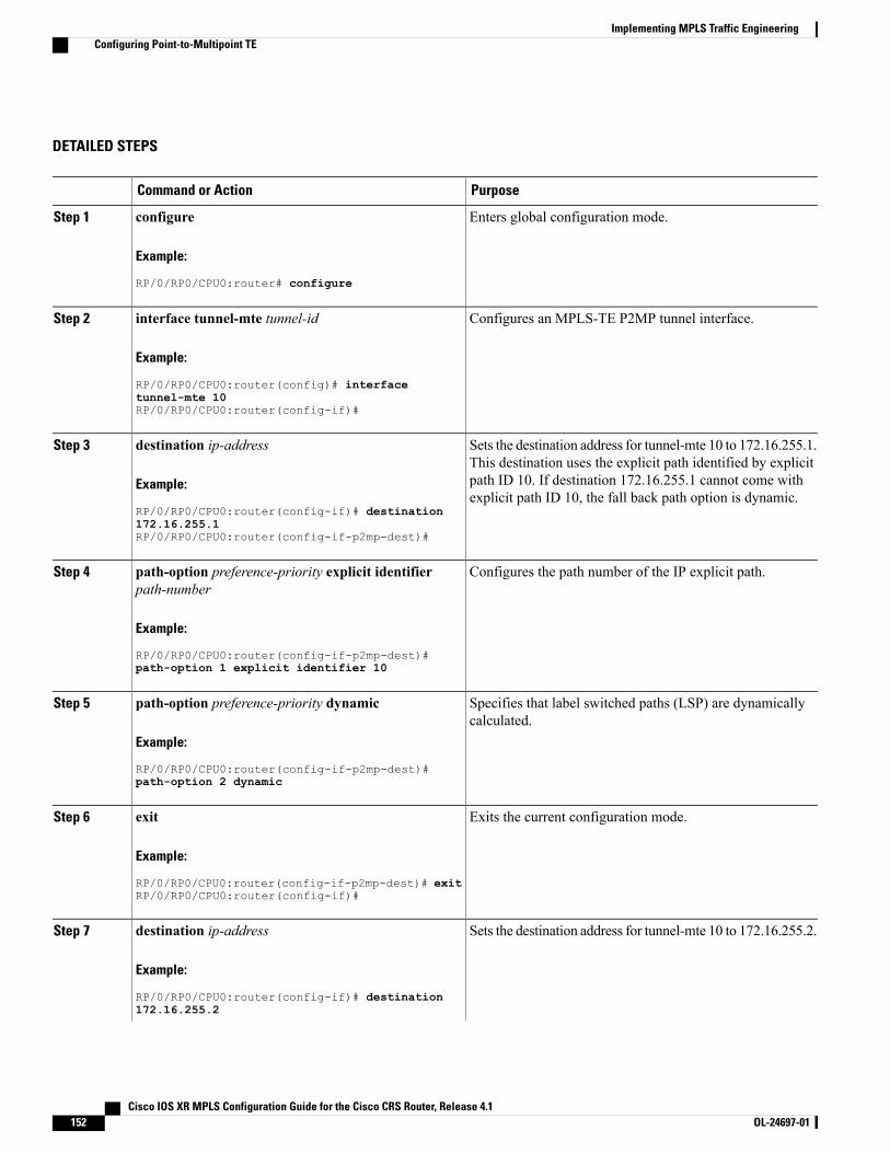
DETAILED STEPS
PurposeCommand or Action
Enters global configuration mode.configure
Example:
RP/0/RP0/CPU0:router# configure
Step 1
Configures an MPLS-TE P2MP tunnel interface.interface tunnel-mte tunnel-id
Example:
RP/0/RP0/CPU0:router(config)# interface
Step 2
tunnel-mte 10RP/0/RP0/CPU0:router(config-if)#
Sets the destination address for tunnel-mte 10 to 172.16.255.1.This destination uses the explicit path identified by explicit
destination ip-address
Example:
RP/0/RP0/CPU0:router(config-if)# destination
Step 3
path ID 10. If destination 172.16.255.1 cannot come withexplicit path ID 10, the fall back path option is dynamic.
172.16.255.1RP/0/RP0/CPU0:router(config-if-p2mp-dest)#
Configures the path number of the IP explicit path.path-option preference-priority explicit identifierpath-number
Step 4
Example:
RP/0/RP0/CPU0:router(config-if-p2mp-dest)#path-option 1 explicit identifier 10
Specifies that label switched paths (LSP) are dynamicallycalculated.
path-option preference-priority dynamic
Example:
RP/0/RP0/CPU0:router(config-if-p2mp-dest)#
Step 5
path-option 2 dynamic
Exits the current configuration mode.exit
Example:
RP/0/RP0/CPU0:router(config-if-p2mp-dest)# exit
Step 6
RP/0/RP0/CPU0:router(config-if)#
Sets the destination address for tunnel-mte 10 to 172.16.255.2.destination ip-address
Example:
RP/0/RP0/CPU0:router(config-if)# destination
Step 7
172.16.255.2
Cisco IOS XR MPLS Configuration Guide for the Cisco CRS Router, Release 4.1152 OL-24697-01
Implementing MPLS Traffic EngineeringConfiguring Point-to-Multipoint TE
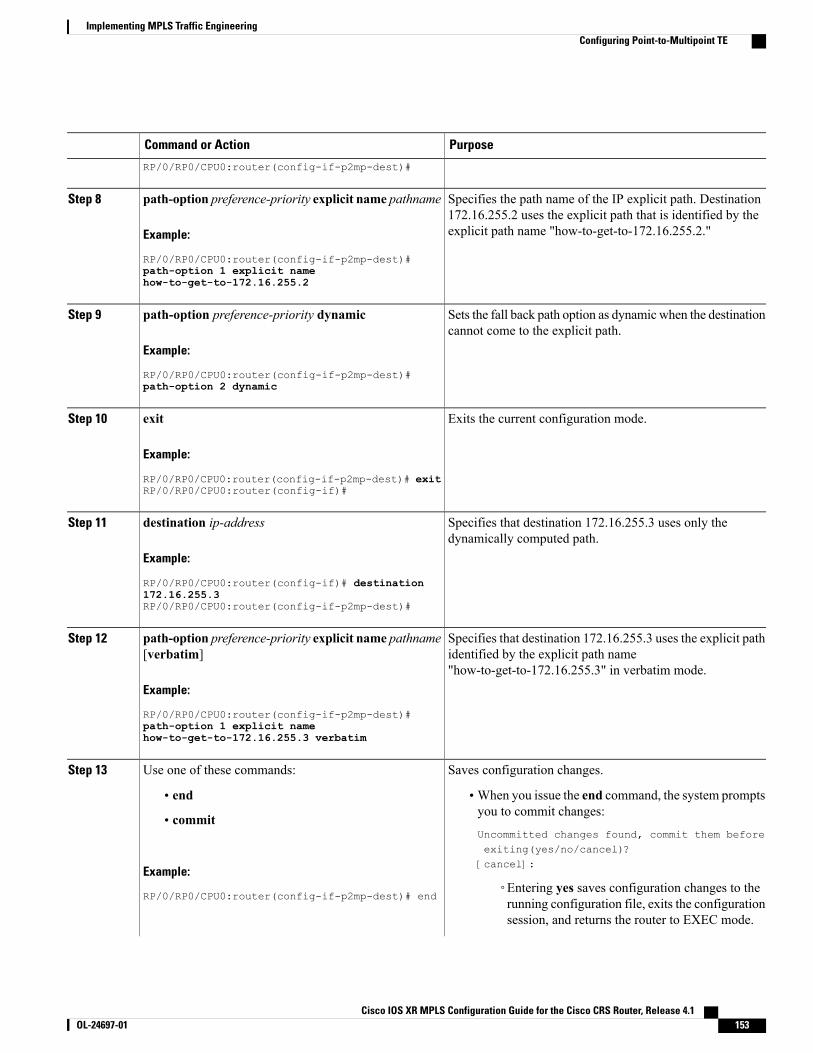
PurposeCommand or Action
RP/0/RP0/CPU0:router(config-if-p2mp-dest)#
Specifies the path name of the IP explicit path. Destination172.16.255.2 uses the explicit path that is identified by theexplicit path name "how-to-get-to-172.16.255.2."
path-option preference-priority explicit name pathname
Example:
RP/0/RP0/CPU0:router(config-if-p2mp-dest)#
Step 8
path-option 1 explicit namehow-to-get-to-172.16.255.2
Sets the fall back path option as dynamic when the destinationcannot come to the explicit path.
path-option preference-priority dynamic
Example:
RP/0/RP0/CPU0:router(config-if-p2mp-dest)#
Step 9
path-option 2 dynamic
Exits the current configuration mode.exit
Example:
RP/0/RP0/CPU0:router(config-if-p2mp-dest)# exit
Step 10
RP/0/RP0/CPU0:router(config-if)#
Specifies that destination 172.16.255.3 uses only thedynamically computed path.
destination ip-address
Example:
RP/0/RP0/CPU0:router(config-if)# destination
Step 11
172.16.255.3RP/0/RP0/CPU0:router(config-if-p2mp-dest)#
Specifies that destination 172.16.255.3 uses the explicit pathidentified by the explicit path name"how-to-get-to-172.16.255.3" in verbatim mode.
path-option preference-priority explicit name pathname[verbatim]
Example:
RP/0/RP0/CPU0:router(config-if-p2mp-dest)#
Step 12
path-option 1 explicit namehow-to-get-to-172.16.255.3 verbatim
Saves configuration changes.Use one of these commands:Step 13
• end •When you issue the end command, the system promptsyou to commit changes:
Uncommitted changes found, commit them beforeexiting(yes/no/cancel)?[cancel]:
• commit
Example:
RP/0/RP0/CPU0:router(config-if-p2mp-dest)# end◦Entering yes saves configuration changes to therunning configuration file, exits the configurationsession, and returns the router to EXEC mode.
Cisco IOS XR MPLS Configuration Guide for the Cisco CRS Router, Release 4.1 OL-24697-01 153
Implementing MPLS Traffic EngineeringConfiguring Point-to-Multipoint TE
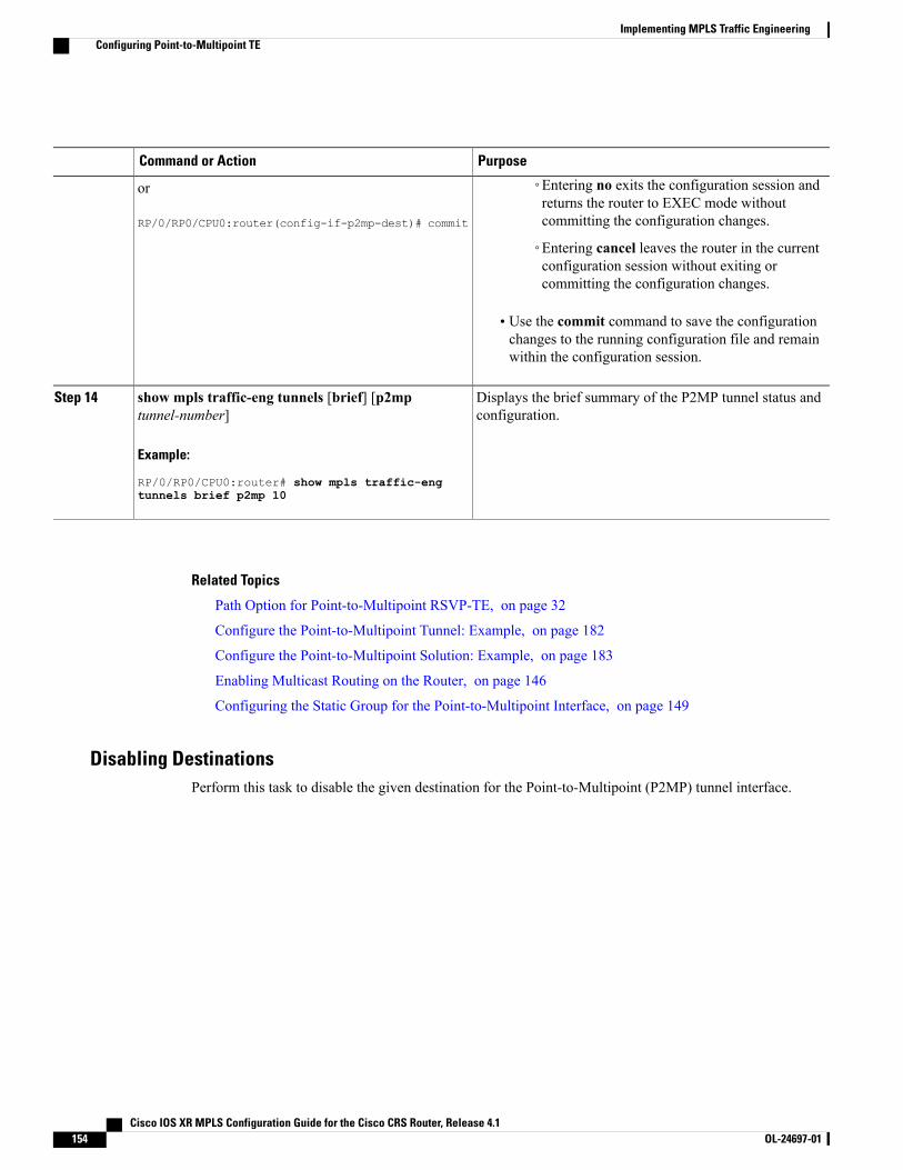
PurposeCommand or Action
or
RP/0/RP0/CPU0:router(config-if-p2mp-dest)# commit
◦Entering no exits the configuration session andreturns the router to EXEC mode withoutcommitting the configuration changes.
◦Entering cancel leaves the router in the currentconfiguration session without exiting orcommitting the configuration changes.
• Use the commit command to save the configurationchanges to the running configuration file and remainwithin the configuration session.
Displays the brief summary of the P2MP tunnel status andconfiguration.
show mpls traffic-eng tunnels [brief] [p2mptunnel-number]
Example:
RP/0/RP0/CPU0:router# show mpls traffic-eng
Step 14
tunnels brief p2mp 10
Related Topics
Path Option for Point-to-Multipoint RSVP-TE, on page 32
Configure the Point-to-Multipoint Tunnel: Example, on page 182
Configure the Point-to-Multipoint Solution: Example, on page 183
Enabling Multicast Routing on the Router, on page 146
Configuring the Static Group for the Point-to-Multipoint Interface, on page 149
Disabling DestinationsPerform this task to disable the given destination for the Point-to-Multipoint (P2MP) tunnel interface.
Cisco IOS XR MPLS Configuration Guide for the Cisco CRS Router, Release 4.1154 OL-24697-01
Implementing MPLS Traffic EngineeringConfiguring Point-to-Multipoint TE
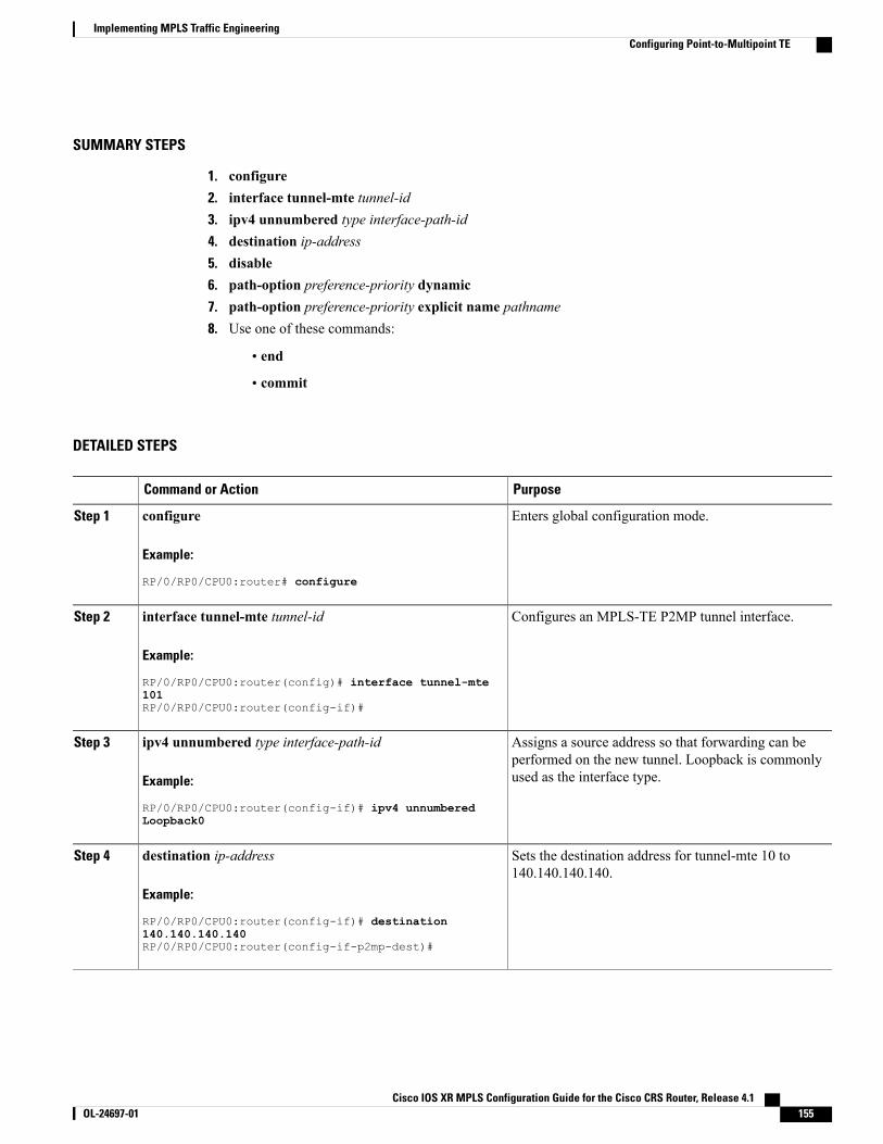
SUMMARY STEPS
1. configure2. interface tunnel-mte tunnel-id3. ipv4 unnumbered type interface-path-id4. destination ip-address5. disable6. path-option preference-priority dynamic7. path-option preference-priority explicit name pathname8. Use one of these commands:
• end
• commit
DETAILED STEPS
PurposeCommand or Action
Enters global configuration mode.configure
Example:
RP/0/RP0/CPU0:router# configure
Step 1
Configures an MPLS-TE P2MP tunnel interface.interface tunnel-mte tunnel-id
Example:
RP/0/RP0/CPU0:router(config)# interface tunnel-mte
Step 2
101RP/0/RP0/CPU0:router(config-if)#
Assigns a source address so that forwarding can beperformed on the new tunnel. Loopback is commonlyused as the interface type.
ipv4 unnumbered type interface-path-id
Example:
RP/0/RP0/CPU0:router(config-if)# ipv4 unnumbered
Step 3
Loopback0
Sets the destination address for tunnel-mte 10 to140.140.140.140.
destination ip-address
Example:
RP/0/RP0/CPU0:router(config-if)# destination
Step 4
140.140.140.140RP/0/RP0/CPU0:router(config-if-p2mp-dest)#
Cisco IOS XR MPLS Configuration Guide for the Cisco CRS Router, Release 4.1 OL-24697-01 155
Implementing MPLS Traffic EngineeringConfiguring Point-to-Multipoint TE
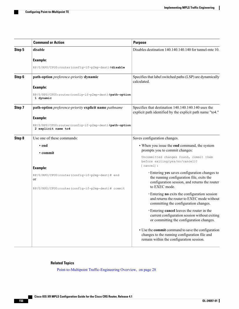
PurposeCommand or Action
Disables destination 140.140.140.140 for tunnel-mte 10.disable
Example:
RP/0/RP0/CPU0:router(config-if-p2mp-dest)#disable
Step 5
Specifies that label switched paths (LSP) are dynamicallycalculated.
path-option preference-priority dynamic
Example:
RP/0/RP0/CPU0:router(config-if-p2mp-dest)#path-option
Step 6
1 dynamic
Specifies that destination 140.140.140.140 uses theexplicit path identified by the explicit path name "to4."
path-option preference-priority explicit name pathname
Example:
RP/0/RP0/CPU0:router(config-if-p2mp-dest)#path-option
Step 7
2 explicit name to4
Saves configuration changes.Use one of these commands:Step 8
• end •When you issue the end command, the systemprompts you to commit changes:
Uncommitted changes found, commit thembefore exiting(yes/no/cancel)?[cancel]:
• commit
Example:
RP/0/RP0/CPU0:router(config-if-p2mp-dest)# end◦Entering yes saves configuration changes tothe running configuration file, exits theor
RP/0/RP0/CPU0:router(config-if-p2mp-dest)# commit
configuration session, and returns the routerto EXEC mode.
◦Entering no exits the configuration sessionand returns the router to EXECmode withoutcommitting the configuration changes.
◦Entering cancel leaves the router in thecurrent configuration session without exitingor committing the configuration changes.
• Use the commit command to save the configurationchanges to the running configuration file andremain within the configuration session.
Related Topics
Point-to-Multipoint Traffic-Engineering Overview, on page 28
Cisco IOS XR MPLS Configuration Guide for the Cisco CRS Router, Release 4.1156 OL-24697-01
Implementing MPLS Traffic EngineeringConfiguring Point-to-Multipoint TE
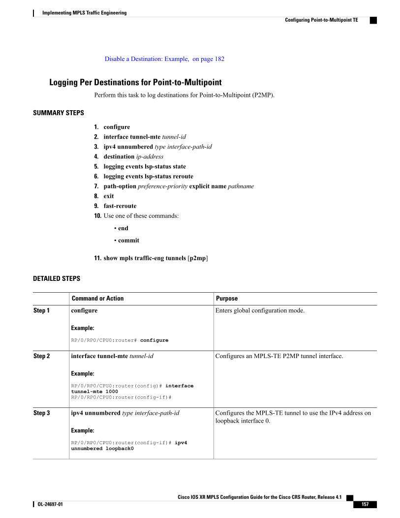
Disable a Destination: Example, on page 182
Logging Per Destinations for Point-to-MultipointPerform this task to log destinations for Point-to-Multipoint (P2MP).
SUMMARY STEPS
1. configure2. interface tunnel-mte tunnel-id3. ipv4 unnumbered type interface-path-id4. destination ip-address5. logging events lsp-status state6. logging events lsp-status reroute7. path-option preference-priority explicit name pathname8. exit9. fast-reroute10. Use one of these commands:
• end
• commit
11. show mpls traffic-eng tunnels [p2mp]
DETAILED STEPS
PurposeCommand or Action
Enters global configuration mode.configure
Example:
RP/0/RP0/CPU0:router# configure
Step 1
Configures an MPLS-TE P2MP tunnel interface.interface tunnel-mte tunnel-id
Example:
RP/0/RP0/CPU0:router(config)# interface
Step 2
tunnel-mte 1000RP/0/RP0/CPU0:router(config-if)#
Configures the MPLS-TE tunnel to use the IPv4 address onloopback interface 0.
ipv4 unnumbered type interface-path-id
Example:
RP/0/RP0/CPU0:router(config-if)# ipv4
Step 3
unnumbered loopback0
Cisco IOS XR MPLS Configuration Guide for the Cisco CRS Router, Release 4.1 OL-24697-01 157
Implementing MPLS Traffic EngineeringConfiguring Point-to-Multipoint TE
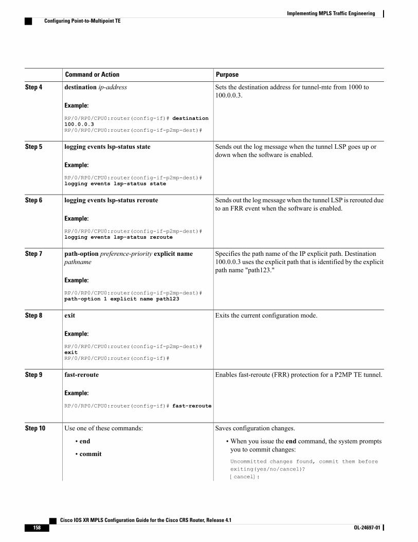
PurposeCommand or Action
Sets the destination address for tunnel-mte from 1000 to100.0.0.3.
destination ip-address
Example:
RP/0/RP0/CPU0:router(config-if)# destination
Step 4
100.0.0.3RP/0/RP0/CPU0:router(config-if-p2mp-dest)#
Sends out the log message when the tunnel LSP goes up ordown when the software is enabled.
logging events lsp-status state
Example:
RP/0/RP0/CPU0:router(config-if-p2mp-dest)#
Step 5
logging events lsp-status state
Sends out the logmessage when the tunnel LSP is rerouted dueto an FRR event when the software is enabled.
logging events lsp-status reroute
Example:
RP/0/RP0/CPU0:router(config-if-p2mp-dest)#
Step 6
logging events lsp-status reroute
Specifies the path name of the IP explicit path. Destination100.0.0.3 uses the explicit path that is identified by the explicitpath name "path123."
path-option preference-priority explicit namepathname
Example:
RP/0/RP0/CPU0:router(config-if-p2mp-dest)#
Step 7
path-option 1 explicit name path123
Exits the current configuration mode.exit
Example:
RP/0/RP0/CPU0:router(config-if-p2mp-dest)#
Step 8
exitRP/0/RP0/CPU0:router(config-if)#
Enables fast-reroute (FRR) protection for a P2MP TE tunnel.fast-reroute
Example:
RP/0/RP0/CPU0:router(config-if)# fast-reroute
Step 9
Saves configuration changes.Use one of these commands:Step 10
• end •When you issue the end command, the system promptsyou to commit changes:
Uncommitted changes found, commit them beforeexiting(yes/no/cancel)?[cancel]:
• commit
Cisco IOS XR MPLS Configuration Guide for the Cisco CRS Router, Release 4.1158 OL-24697-01
Implementing MPLS Traffic EngineeringConfiguring Point-to-Multipoint TE
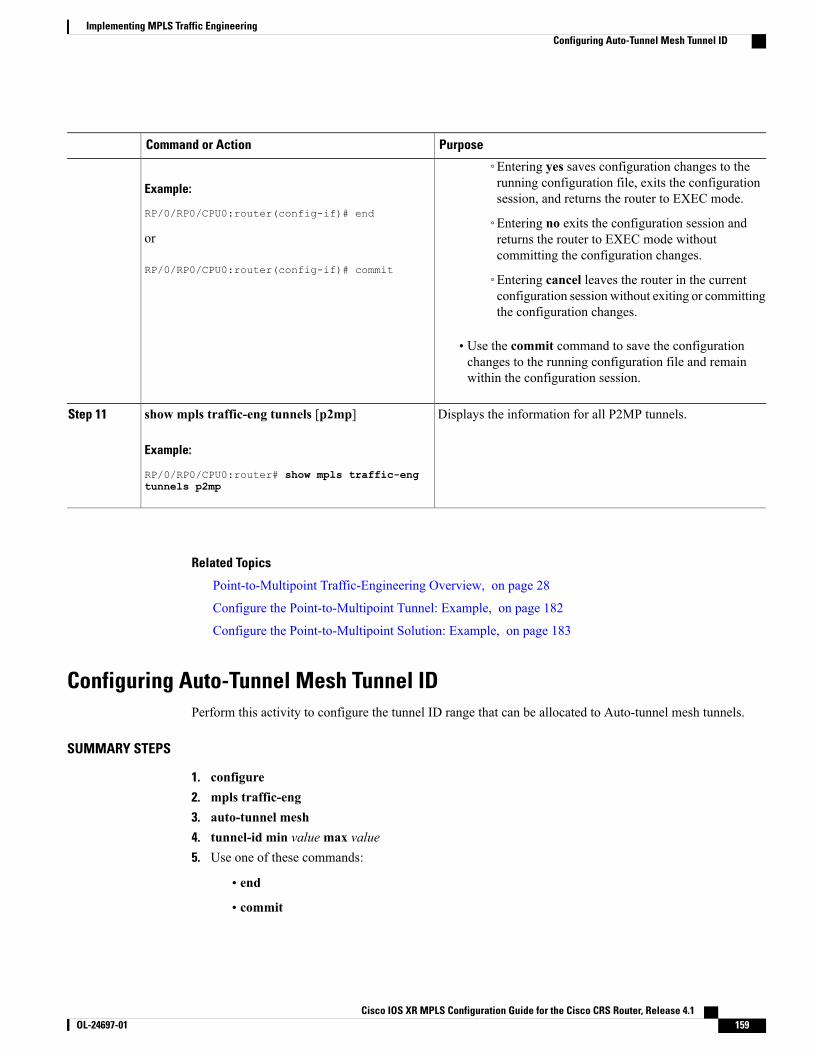
PurposeCommand or Action
Example:
RP/0/RP0/CPU0:router(config-if)# end
◦Entering yes saves configuration changes to therunning configuration file, exits the configurationsession, and returns the router to EXEC mode.
◦Entering no exits the configuration session andreturns the router to EXEC mode withoutcommitting the configuration changes.
or
RP/0/RP0/CPU0:router(config-if)# commit◦Entering cancel leaves the router in the currentconfiguration session without exiting or committingthe configuration changes.
• Use the commit command to save the configurationchanges to the running configuration file and remainwithin the configuration session.
Displays the information for all P2MP tunnels.show mpls traffic-eng tunnels [p2mp]
Example:
RP/0/RP0/CPU0:router# show mpls traffic-eng
Step 11
tunnels p2mp
Related Topics
Point-to-Multipoint Traffic-Engineering Overview, on page 28
Configure the Point-to-Multipoint Tunnel: Example, on page 182
Configure the Point-to-Multipoint Solution: Example, on page 183
Configuring Auto-Tunnel Mesh Tunnel IDPerform this activity to configure the tunnel ID range that can be allocated to Auto-tunnel mesh tunnels.
SUMMARY STEPS
1. configure2. mpls traffic-eng3. auto-tunnel mesh4. tunnel-id min valuemax value5. Use one of these commands:
• end
• commit
Cisco IOS XR MPLS Configuration Guide for the Cisco CRS Router, Release 4.1 OL-24697-01 159
Implementing MPLS Traffic EngineeringConfiguring Auto-Tunnel Mesh Tunnel ID
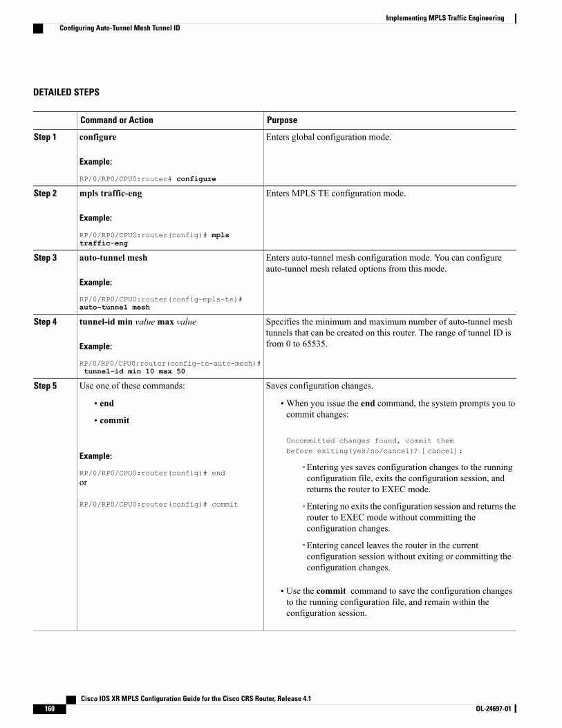
DETAILED STEPS
PurposeCommand or Action
Enters global configuration mode.configure
Example:
RP/0/RP0/CPU0:router# configure
Step 1
Enters MPLS TE configuration mode.mpls traffic-eng
Example:
RP/0/RP0/CPU0:router(config)# mplstraffic-eng
Step 2
Enters auto-tunnel mesh configuration mode. You can configureauto-tunnel mesh related options from this mode.
auto-tunnel mesh
Example:
RP/0/RP0/CPU0:router(config-mpls-te)#auto-tunnel mesh
Step 3
Specifies the minimum and maximum number of auto-tunnel meshtunnels that can be created on this router. The range of tunnel ID isfrom 0 to 65535.
tunnel-id min valuemax value
Example:
RP/0/RP0/CPU0:router(config-te-auto-mesh)#tunnel-id min 10 max 50
Step 4
Saves configuration changes.Use one of these commands:Step 5
• end •When you issue the end command, the system prompts you tocommit changes:
Uncommitted changes found, commit thembefore exiting(yes/no/cancel)? [cancel]:
• commit
Example:
RP/0/RP0/CPU0:router(config)# end◦Entering yes saves configuration changes to the runningconfiguration file, exits the configuration session, andreturns the router to EXEC mode.
or
RP/0/RP0/CPU0:router(config)# commit ◦Entering no exits the configuration session and returns therouter to EXEC mode without committing theconfiguration changes.
◦Entering cancel leaves the router in the currentconfiguration session without exiting or committing theconfiguration changes.
• Use the commit command to save the configuration changesto the running configuration file, and remain within theconfiguration session.
Cisco IOS XR MPLS Configuration Guide for the Cisco CRS Router, Release 4.1160 OL-24697-01
Implementing MPLS Traffic EngineeringConfiguring Auto-Tunnel Mesh Tunnel ID
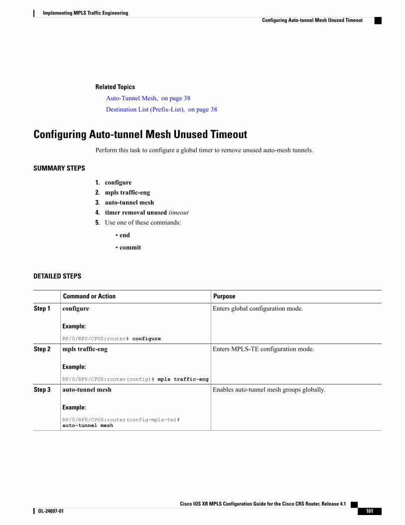
Related Topics
Auto-Tunnel Mesh, on page 38
Destination List (Prefix-List), on page 38
Configuring Auto-tunnel Mesh Unused TimeoutPerform this task to configure a global timer to remove unused auto-mesh tunnels.
SUMMARY STEPS
1. configure2. mpls traffic-eng3. auto-tunnel mesh4. timer removal unused timeout5. Use one of these commands:
• end
• commit
DETAILED STEPS
PurposeCommand or Action
Enters global configuration mode.configure
Example:
RP/0/RP0/CPU0:router# configure
Step 1
Enters MPLS-TE configuration mode.mpls traffic-eng
Example:
RP/0/RP0/CPU0:router(config)# mpls traffic-eng
Step 2
Enables auto-tunnel mesh groups globally.auto-tunnel mesh
Example:
RP/0/RP0/CPU0:router(config-mpls-te)#auto-tunnel mesh
Step 3
Cisco IOS XR MPLS Configuration Guide for the Cisco CRS Router, Release 4.1 OL-24697-01 161
Implementing MPLS Traffic EngineeringConfiguring Auto-tunnel Mesh Unused Timeout
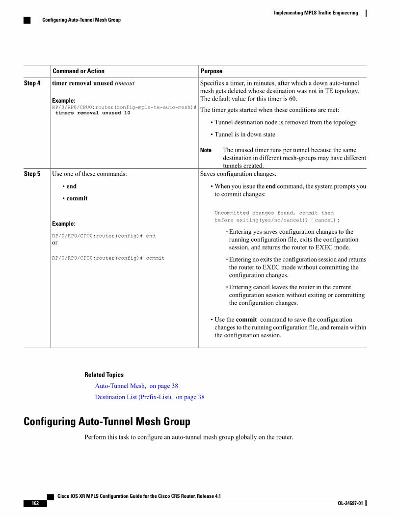
PurposeCommand or Action
Specifies a timer, in minutes, after which a down auto-tunnelmesh gets deleted whose destination was not in TE topology.The default value for this timer is 60.
timer removal unused timeout
Example:RP/0/RP0/CPU0:router(config-mpls-te-auto-mesh)#timers removal unused 10
Step 4
The timer gets started when these conditions are met:
• Tunnel destination node is removed from the topology
• Tunnel is in down state
The unused timer runs per tunnel because the samedestination in different mesh-groups may have differenttunnels created.
Note
Saves configuration changes.Use one of these commands:Step 5
• end •When you issue the end command, the system prompts youto commit changes:
Uncommitted changes found, commit thembefore exiting(yes/no/cancel)? [cancel]:
• commit
Example:
RP/0/RP0/CPU0:router(config)# end◦Entering yes saves configuration changes to therunning configuration file, exits the configurationsession, and returns the router to EXEC mode.
or
RP/0/RP0/CPU0:router(config)# commit ◦Entering no exits the configuration session and returnsthe router to EXEC mode without committing theconfiguration changes.
◦Entering cancel leaves the router in the currentconfiguration session without exiting or committingthe configuration changes.
• Use the commit command to save the configurationchanges to the running configuration file, and remain withinthe configuration session.
Related Topics
Auto-Tunnel Mesh, on page 38
Destination List (Prefix-List), on page 38
Configuring Auto-Tunnel Mesh GroupPerform this task to configure an auto-tunnel mesh group globally on the router.
Cisco IOS XR MPLS Configuration Guide for the Cisco CRS Router, Release 4.1162 OL-24697-01
Implementing MPLS Traffic EngineeringConfiguring Auto-Tunnel Mesh Group
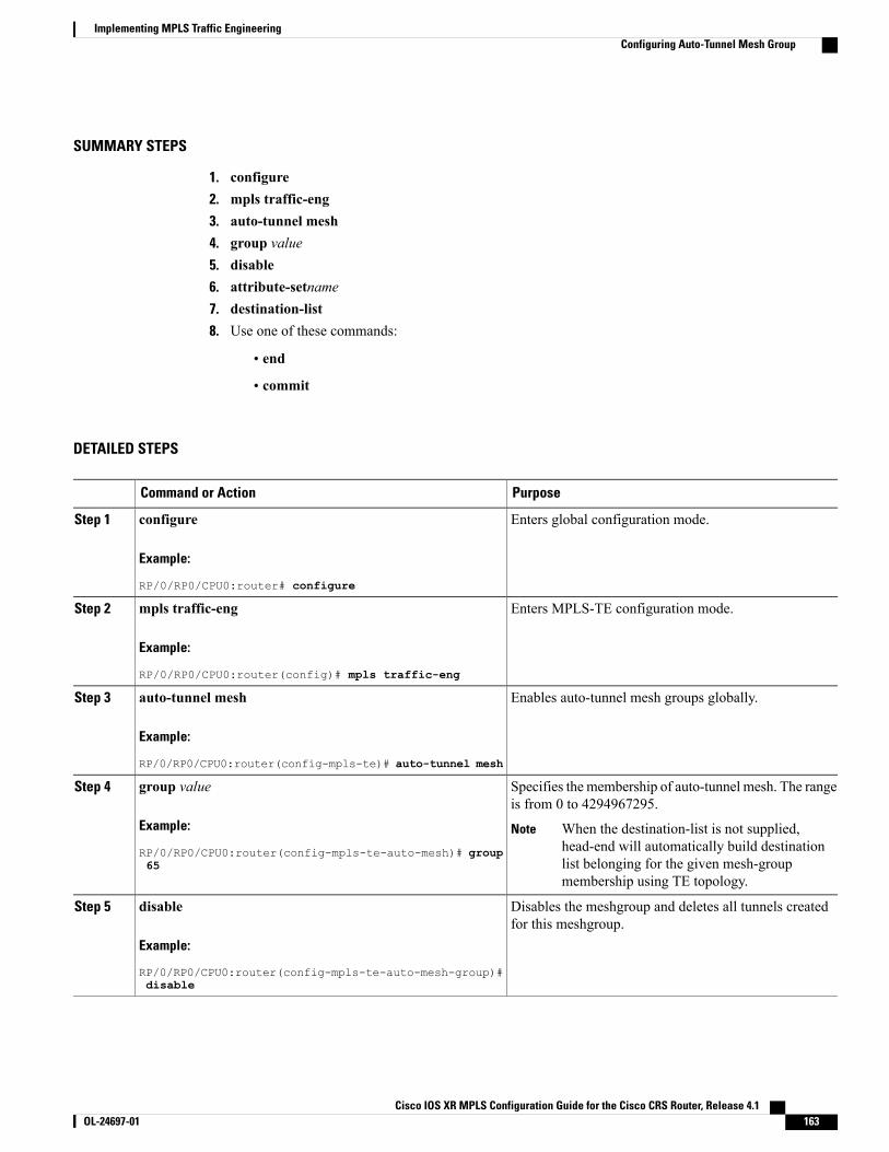
SUMMARY STEPS
1. configure2. mpls traffic-eng3. auto-tunnel mesh4. group value5. disable6. attribute-setname7. destination-list8. Use one of these commands:
• end
• commit
DETAILED STEPS
PurposeCommand or Action
Enters global configuration mode.configure
Example:
RP/0/RP0/CPU0:router# configure
Step 1
Enters MPLS-TE configuration mode.mpls traffic-eng
Example:
RP/0/RP0/CPU0:router(config)# mpls traffic-eng
Step 2
Enables auto-tunnel mesh groups globally.auto-tunnel mesh
Example:
RP/0/RP0/CPU0:router(config-mpls-te)# auto-tunnel mesh
Step 3
Specifies the membership of auto-tunnel mesh. The rangeis from 0 to 4294967295.
group value
Example:
RP/0/RP0/CPU0:router(config-mpls-te-auto-mesh)# group65
Step 4
When the destination-list is not supplied,head-end will automatically build destinationlist belonging for the given mesh-groupmembership using TE topology.
Note
Disables the meshgroup and deletes all tunnels createdfor this meshgroup.
disable
Example:
RP/0/RP0/CPU0:router(config-mpls-te-auto-mesh-group)#disable
Step 5
Cisco IOS XR MPLS Configuration Guide for the Cisco CRS Router, Release 4.1 OL-24697-01 163
Implementing MPLS Traffic EngineeringConfiguring Auto-Tunnel Mesh Group
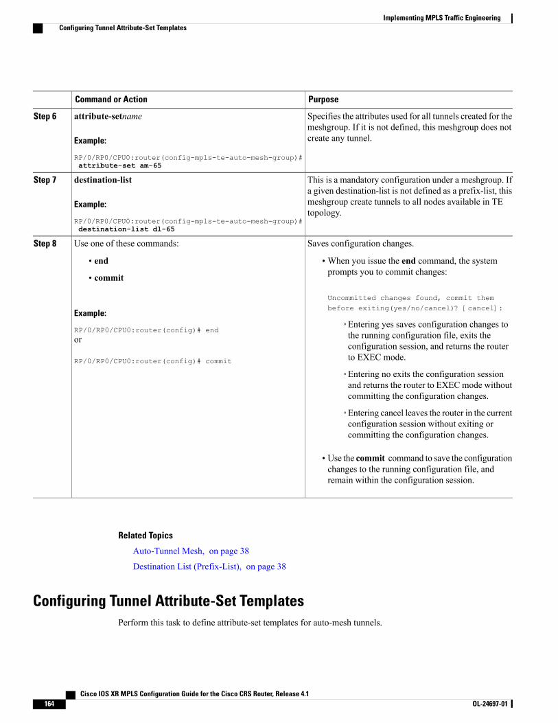
PurposeCommand or Action
Specifies the attributes used for all tunnels created for themeshgroup. If it is not defined, this meshgroup does notcreate any tunnel.
attribute-setname
Example:
RP/0/RP0/CPU0:router(config-mpls-te-auto-mesh-group)#attribute-set am-65
Step 6
This is a mandatory configuration under a meshgroup. Ifa given destination-list is not defined as a prefix-list, this
destination-list
Example:
RP/0/RP0/CPU0:router(config-mpls-te-auto-mesh-group)#destination-list dl-65
Step 7
meshgroup create tunnels to all nodes available in TEtopology.
Saves configuration changes.Use one of these commands:Step 8
• end •When you issue the end command, the systemprompts you to commit changes:
Uncommitted changes found, commit thembefore exiting(yes/no/cancel)? [cancel]:
• commit
Example:
RP/0/RP0/CPU0:router(config)# end◦Entering yes saves configuration changes tothe running configuration file, exits theor
RP/0/RP0/CPU0:router(config)# commit
configuration session, and returns the routerto EXEC mode.
◦Entering no exits the configuration sessionand returns the router to EXECmode withoutcommitting the configuration changes.
◦Entering cancel leaves the router in the currentconfiguration session without exiting orcommitting the configuration changes.
• Use the commit command to save the configurationchanges to the running configuration file, andremain within the configuration session.
Related Topics
Auto-Tunnel Mesh, on page 38
Destination List (Prefix-List), on page 38
Configuring Tunnel Attribute-Set TemplatesPerform this task to define attribute-set templates for auto-mesh tunnels.
Cisco IOS XR MPLS Configuration Guide for the Cisco CRS Router, Release 4.1164 OL-24697-01
Implementing MPLS Traffic EngineeringConfiguring Tunnel Attribute-Set Templates
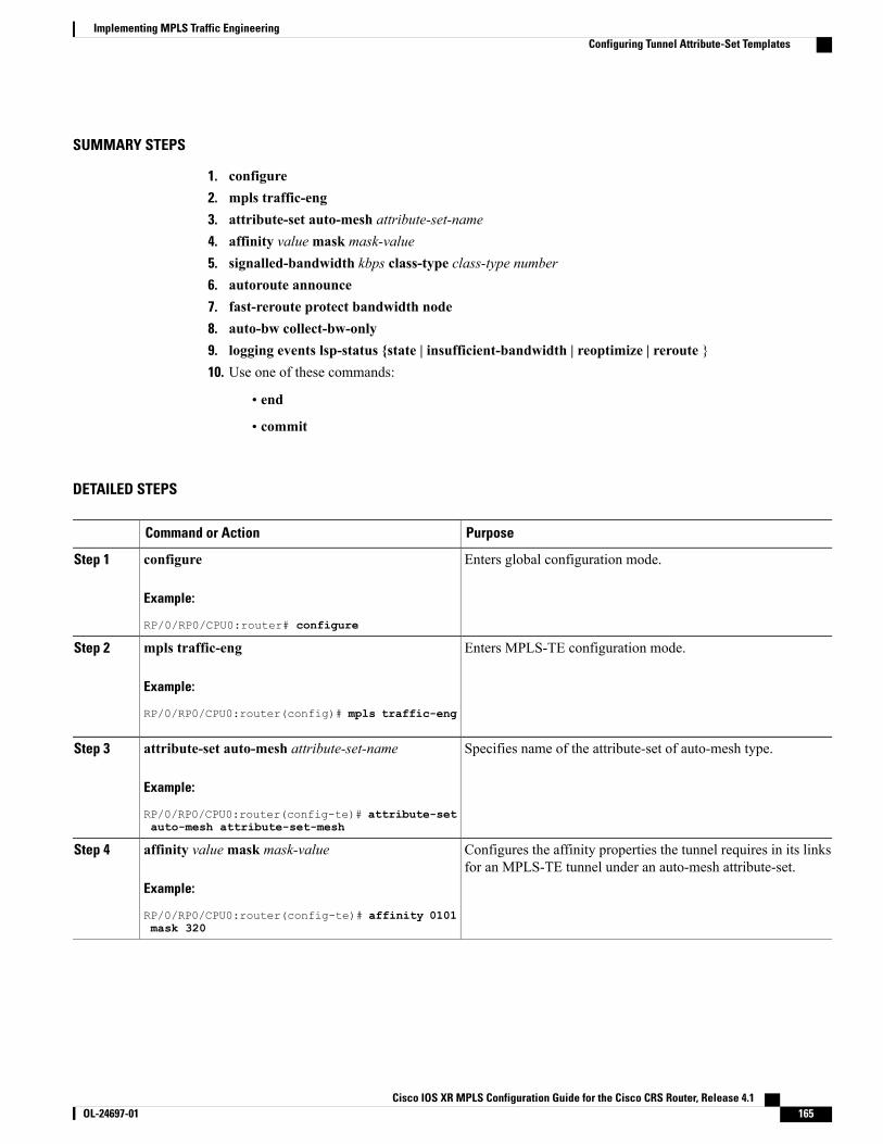
SUMMARY STEPS
1. configure2. mpls traffic-eng3. attribute-set auto-mesh attribute-set-name4. affinity valuemask mask-value5. signalled-bandwidth kbps class-type class-type number6. autoroute announce7. fast-reroute protect bandwidth node8. auto-bw collect-bw-only9. logging events lsp-status {state | insufficient-bandwidth | reoptimize | reroute }10. Use one of these commands:
• end
• commit
DETAILED STEPS
PurposeCommand or Action
Enters global configuration mode.configure
Example:
RP/0/RP0/CPU0:router# configure
Step 1
Enters MPLS-TE configuration mode.mpls traffic-eng
Example:
RP/0/RP0/CPU0:router(config)# mpls traffic-eng
Step 2
Specifies name of the attribute-set of auto-mesh type.attribute-set auto-mesh attribute-set-name
Example:
RP/0/RP0/CPU0:router(config-te)# attribute-setauto-mesh attribute-set-mesh
Step 3
Configures the affinity properties the tunnel requires in its linksfor an MPLS-TE tunnel under an auto-mesh attribute-set.
affinity valuemask mask-value
Example:
RP/0/RP0/CPU0:router(config-te)# affinity 0101mask 320
Step 4
Cisco IOS XR MPLS Configuration Guide for the Cisco CRS Router, Release 4.1 OL-24697-01 165
Implementing MPLS Traffic EngineeringConfiguring Tunnel Attribute-Set Templates
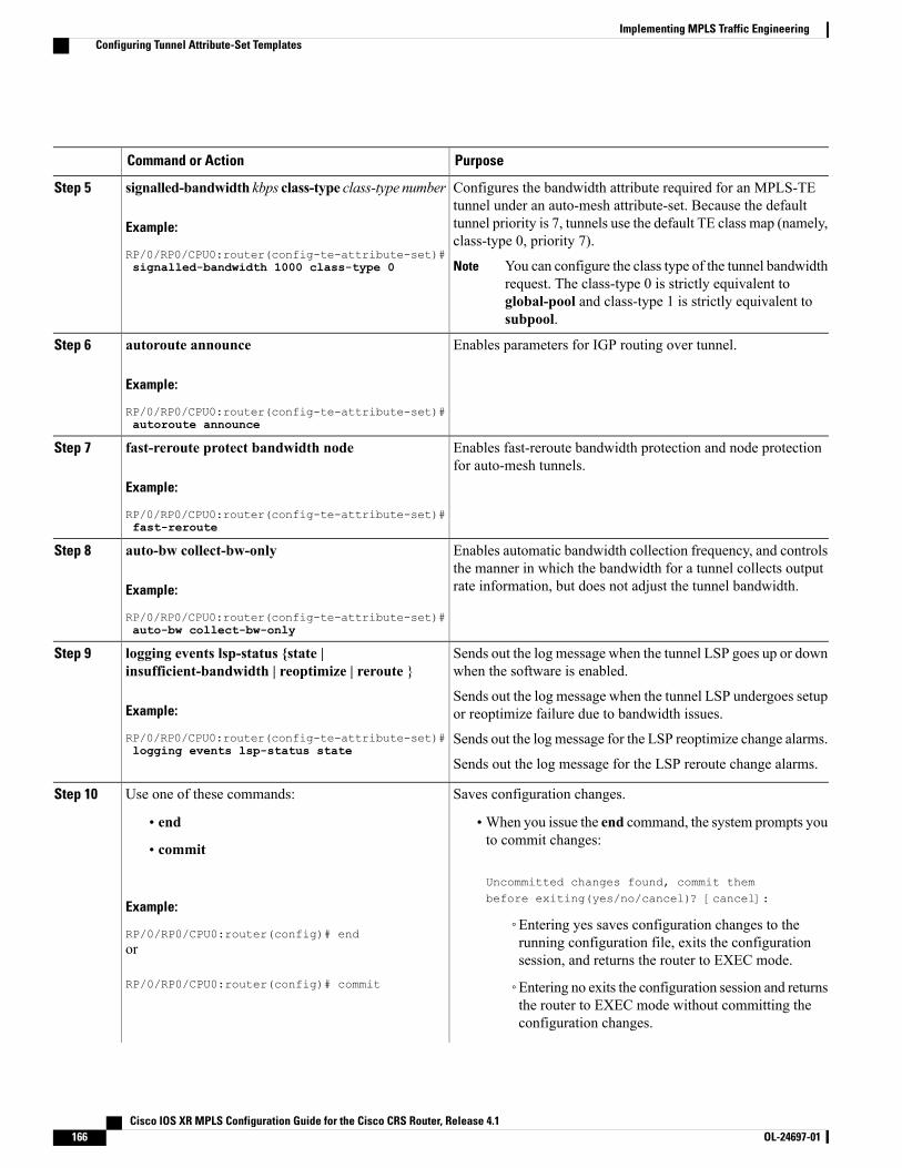
PurposeCommand or Action
Configures the bandwidth attribute required for an MPLS-TEtunnel under an auto-mesh attribute-set. Because the default
signalled-bandwidth kbps class-type class-type number
Example:
RP/0/RP0/CPU0:router(config-te-attribute-set)#signalled-bandwidth 1000 class-type 0
Step 5
tunnel priority is 7, tunnels use the default TE class map (namely,class-type 0, priority 7).
You can configure the class type of the tunnel bandwidthrequest. The class-type 0 is strictly equivalent toglobal-pool and class-type 1 is strictly equivalent tosubpool.
Note
Enables parameters for IGP routing over tunnel.autoroute announce
Example:
RP/0/RP0/CPU0:router(config-te-attribute-set)#autoroute announce
Step 6
Enables fast-reroute bandwidth protection and node protectionfor auto-mesh tunnels.
fast-reroute protect bandwidth node
Example:
RP/0/RP0/CPU0:router(config-te-attribute-set)#fast-reroute
Step 7
Enables automatic bandwidth collection frequency, and controlsthe manner in which the bandwidth for a tunnel collects outputrate information, but does not adjust the tunnel bandwidth.
auto-bw collect-bw-only
Example:
RP/0/RP0/CPU0:router(config-te-attribute-set)#auto-bw collect-bw-only
Step 8
Sends out the log message when the tunnel LSP goes up or downwhen the software is enabled.
logging events lsp-status {state |insufficient-bandwidth | reoptimize | reroute }
Step 9
Example:
RP/0/RP0/CPU0:router(config-te-attribute-set)#logging events lsp-status state
Sends out the log message when the tunnel LSP undergoes setupor reoptimize failure due to bandwidth issues.
Sends out the log message for the LSP reoptimize change alarms.
Sends out the log message for the LSP reroute change alarms.
Saves configuration changes.Use one of these commands:Step 10
• end •When you issue the end command, the system prompts youto commit changes:
Uncommitted changes found, commit thembefore exiting(yes/no/cancel)? [cancel]:
• commit
Example:
RP/0/RP0/CPU0:router(config)# end◦Entering yes saves configuration changes to therunning configuration file, exits the configurationsession, and returns the router to EXEC mode.
or
RP/0/RP0/CPU0:router(config)# commit ◦Entering no exits the configuration session and returnsthe router to EXEC mode without committing theconfiguration changes.
Cisco IOS XR MPLS Configuration Guide for the Cisco CRS Router, Release 4.1166 OL-24697-01
Implementing MPLS Traffic EngineeringConfiguring Tunnel Attribute-Set Templates
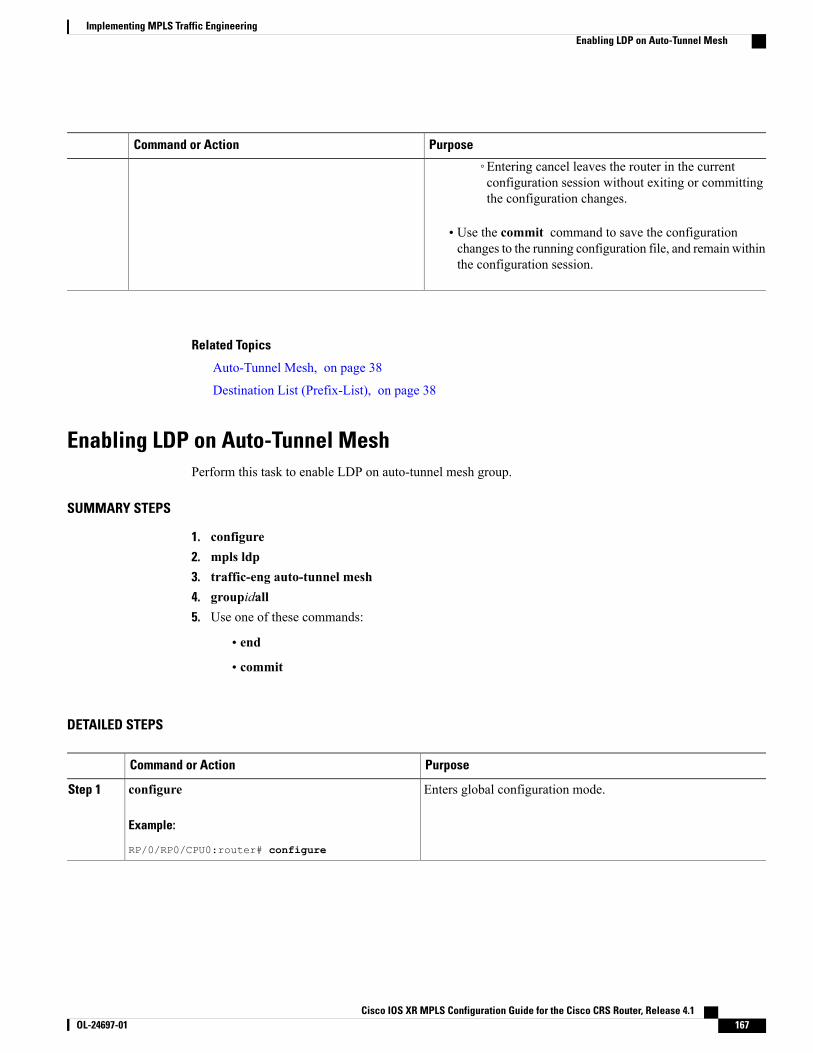
PurposeCommand or Action
◦Entering cancel leaves the router in the currentconfiguration session without exiting or committingthe configuration changes.
• Use the commit command to save the configurationchanges to the running configuration file, and remain withinthe configuration session.
Related Topics
Auto-Tunnel Mesh, on page 38
Destination List (Prefix-List), on page 38
Enabling LDP on Auto-Tunnel MeshPerform this task to enable LDP on auto-tunnel mesh group.
SUMMARY STEPS
1. configure2. mpls ldp3. traffic-eng auto-tunnel mesh4. groupidall5. Use one of these commands:
• end
• commit
DETAILED STEPS
PurposeCommand or Action
Enters global configuration mode.configure
Example:
RP/0/RP0/CPU0:router# configure
Step 1
Cisco IOS XR MPLS Configuration Guide for the Cisco CRS Router, Release 4.1 OL-24697-01 167
Implementing MPLS Traffic EngineeringEnabling LDP on Auto-Tunnel Mesh
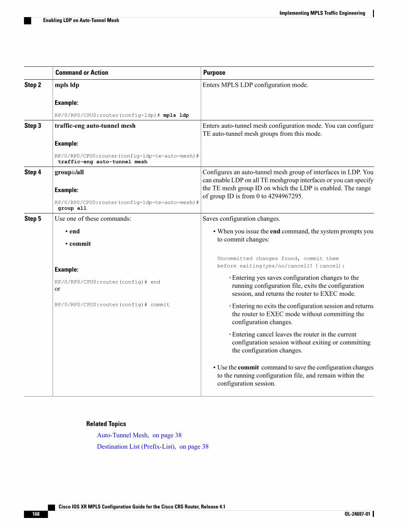
PurposeCommand or Action
Enters MPLS LDP configuration mode.mpls ldp
Example:
RP/0/RP0/CPU0:router(config-ldp)# mpls ldp
Step 2
Enters auto-tunnel mesh configuration mode. You can configureTE auto-tunnel mesh groups from this mode.
traffic-eng auto-tunnel mesh
Example:
RP/0/RP0/CPU0:router(config-ldp-te-auto-mesh)#traffic-eng auto-tunnel mesh
Step 3
Configures an auto-tunnel mesh group of interfaces in LDP. Youcan enable LDP on all TEmeshgroup interfaces or you can specify
groupidall
Example:
RP/0/RP0/CPU0:router(config-ldp-te-auto-mesh)#group all
Step 4
the TE mesh group ID on which the LDP is enabled. The rangeof group ID is from 0 to 4294967295.
Saves configuration changes.Use one of these commands:Step 5
• end •When you issue the end command, the system prompts youto commit changes:
Uncommitted changes found, commit thembefore exiting(yes/no/cancel)? [cancel]:
• commit
Example:
RP/0/RP0/CPU0:router(config)# end◦Entering yes saves configuration changes to therunning configuration file, exits the configurationsession, and returns the router to EXEC mode.
or
RP/0/RP0/CPU0:router(config)# commit ◦Entering no exits the configuration session and returnsthe router to EXEC mode without committing theconfiguration changes.
◦Entering cancel leaves the router in the currentconfiguration session without exiting or committingthe configuration changes.
• Use the commit command to save the configuration changesto the running configuration file, and remain within theconfiguration session.
Related Topics
Auto-Tunnel Mesh, on page 38
Destination List (Prefix-List), on page 38
Cisco IOS XR MPLS Configuration Guide for the Cisco CRS Router, Release 4.1168 OL-24697-01
Implementing MPLS Traffic EngineeringEnabling LDP on Auto-Tunnel Mesh
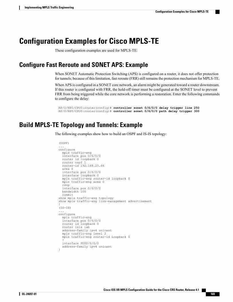
Configuration Examples for Cisco MPLS-TEThese configuration examples are used for MPLS-TE:
Configure Fast Reroute and SONET APS: ExampleWhen SONET Automatic Protection Switching (APS) is configured on a router, it does not offer protectionfor tunnels; because of this limitation, fast reroute (FRR) still remains the protection mechanism forMPLS-TE.
When APS is configured in a SONET core network, an alarmmight be generated toward a router downstream.If this router is configured with FRR, the hold-off timer must be configured at the SONET level to preventFRR from being triggered while the core network is performing a restoration. Enter the following commandsto configure the delay:
RP/0/RP0/CPU0:router(config)# controller sonet 0/6/0/0 delay trigger line 250RP/0/RP0/CPU0:router(config)# controller sonet 0/6/0/0 path delay trigger 300
Build MPLS-TE Topology and Tunnels: ExampleThe following examples show how to build an OSPF and IS-IS topology:
(OSPF)...configurempls traffic-enginterface pos 0/6/0/0router id loopback 0router ospf 1router-id 192.168.25.66area 0interface pos 0/6/0/0interface loopback 0mpls traffic-eng router-id loopback 0mpls traffic-eng area 0rsvpinterface pos 0/6/0/0bandwidth 100commit
show mpls traffic-eng topologyshow mpls traffic-eng link-management advertisement!(IS-IS)...configurempls traffic-enginterface pos 0/6/0/0router id loopback 0router isis labaddress-family ipv4 unicastmpls traffic-eng level 2mpls traffic-eng router-id Loopback 0!interface POS0/0/0/0address-family ipv4 unicast
!
Cisco IOS XR MPLS Configuration Guide for the Cisco CRS Router, Release 4.1 OL-24697-01 169
Implementing MPLS Traffic EngineeringConfiguration Examples for Cisco MPLS-TE
The following example shows how to configure tunnel interfaces:
interface tunnel-te1destination 192.168.92.125ipv4 unnumbered loopback 0path-option l dynamicbandwidth 100commit
show mpls traffic-eng tunnelsshow ipv4 interface briefshow mpls traffic-eng link-management admission-control!interface tunnel-te1autoroute announceroute ipv4 192.168.12.52/32 tunnel-te1commit
ping 192.168.12.52show mpls traffic autoroute!interface tunnel-te1fast-reroutempls traffic-eng interface pos 0/6/0/0backup-path tunnel-te 2interface tunnel-te2backup-bw global-pool 5000ipv4 unnumbered loopback 0path-option l explicit name backup-pathdestination 192.168.92.125commitshow mpls traffic-eng tunnels backupshow mpls traffic-eng fast-reroute database!rsvpinterface pos 0/6/0/0bandwidth 100 150 sub-pool 50interface tunnel-te1bandwidth sub-pool 10
commit
Related Topics
Building MPLS-TE Topology, on page 39Creating an MPLS-TE Tunnel, on page 42How MPLS-TE Works, on page 3
Configure IETF DS-TE Tunnels: ExampleThe following example shows how to configure DS-TE:
rsvpinterface pos 0/6/0/0bandwidth rdm 100 150 bc1 50mpls traffic-engds-te mode ietfinterface tunnel-te 1bandwidth 10 class-type 1commit
configurersvp interface 0/6/0/0bandwidth mam max-reservable-bw 400 bc0 300 bc1 200mpls traffic-engds-te mode ietfds-te model maminterface tunnel-te 1bandwidth 10 class-type 1
Cisco IOS XR MPLS Configuration Guide for the Cisco CRS Router, Release 4.1170 OL-24697-01
Implementing MPLS Traffic EngineeringConfigure IETF DS-TE Tunnels: Example
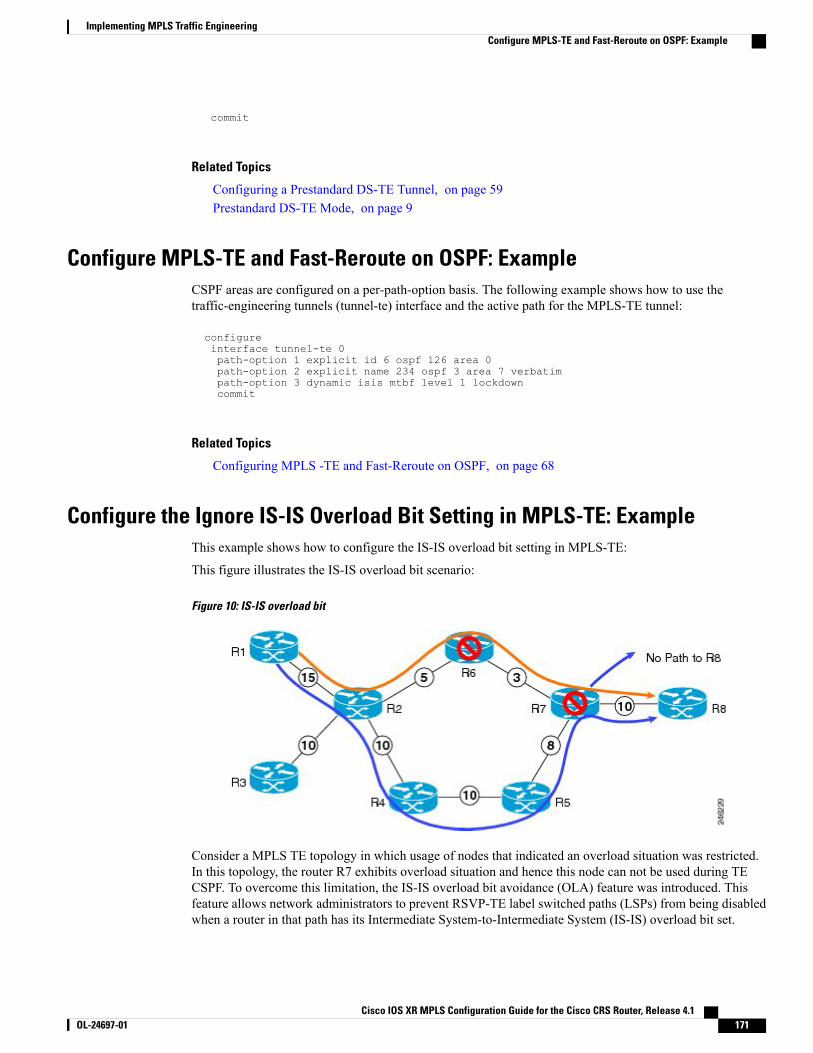
commit
Related Topics
Configuring a Prestandard DS-TE Tunnel, on page 59Prestandard DS-TE Mode, on page 9
Configure MPLS-TE and Fast-Reroute on OSPF: ExampleCSPF areas are configured on a per-path-option basis. The following example shows how to use thetraffic-engineering tunnels (tunnel-te) interface and the active path for the MPLS-TE tunnel:
configureinterface tunnel-te 0path-option 1 explicit id 6 ospf 126 area 0path-option 2 explicit name 234 ospf 3 area 7 verbatimpath-option 3 dynamic isis mtbf level 1 lockdowncommit
Related Topics
Configuring MPLS -TE and Fast-Reroute on OSPF, on page 68
Configure the Ignore IS-IS Overload Bit Setting in MPLS-TE: ExampleThis example shows how to configure the IS-IS overload bit setting in MPLS-TE:
This figure illustrates the IS-IS overload bit scenario:
Figure 10: IS-IS overload bit
Consider a MPLS TE topology in which usage of nodes that indicated an overload situation was restricted.In this topology, the router R7 exhibits overload situation and hence this node can not be used during TECSPF. To overcome this limitation, the IS-IS overload bit avoidance (OLA) feature was introduced. Thisfeature allows network administrators to prevent RSVP-TE label switched paths (LSPs) from being disabledwhen a router in that path has its Intermediate System-to-Intermediate System (IS-IS) overload bit set.
Cisco IOS XR MPLS Configuration Guide for the Cisco CRS Router, Release 4.1 OL-24697-01 171
Implementing MPLS Traffic EngineeringConfigure MPLS-TE and Fast-Reroute on OSPF: Example
The IS-IS overload bit avoidance feature is activated at router R1 using this command:mpls traffic-eng path-selection ignore overload
configurempls traffic-engpath-selection ignore overloadcommit
Related Topics
Configuring the Ignore Integrated IS-IS Overload Bit Setting in MPLS-TE, on page 70Ignore Intermediate System-to-Intermediate System Overload Bit Setting in MPLS-TE, on page 13
Configure GMPLS: ExampleThis example shows how to set up headend and tailend routers with bidirectional optical unnumbered tunnelsusing numbered TE links:
Headend Router
router ospf roswellrouter-id 11.11.11.11nsf ciscoarea 23!area 51interface Loopback 0!interface MgmtEth0/0/CPU0/1!interface POS0/4/0/1!!mpls traffic-eng router-id Loopback 0mpls traffic-eng area 51!
rsvpinterface POS0/2/0/3bandwidth 2000!!interface tunnel-gte 1ipv4 unnumbered Loopback 0switching transit fsc encoding
sonetsdhswitching endpoint psc1 encoding packetpriority 3 3signalled-bandwidth 500destination 55.55.55.55path-option 1 dynamic!
mpls traffic-enginterface POS0/2/0/3flooding-igp ospf roswell area 51switching key 1encoding packetcapability psc1!switching linkencoding
sonetsdh
Cisco IOS XR MPLS Configuration Guide for the Cisco CRS Router, Release 4.1172 OL-24697-01
Implementing MPLS Traffic EngineeringConfigure GMPLS: Example
capability fsc!lmp data-link adjacencyneighbor gmpls5remote te-link-id ipv4 10.0.0.5remote interface-id unnum 12remote switching-capability psc1!!lmp neighbor gmpls5ipcc routedremote node-id 55.55.55.55!!
Tailend Router
router ospf roswellrouter-id 55.55.55.55nsf ciscoarea 23!area 51interface Loopback 0!interface MgmtEth0/0/CPU0/1!interface POS0/4/0/2!!mpls traffic-eng router-id Loopback 0mpls traffic-eng area 51!
mpls traffic-enginterface POS0/2/0/3flooding-igp ospf roswell area 51switching key 1encoding packetcapability psc1!switching linkencoding
sonetsdhcapability fsc!lmp data-link adjacencyneighbor gmpls1remote te-link-id ipv4 10.0.0.1remote interface-id unnum 12remote switching-capability psc1!!lmp neighbor gmpls1ipcc routedremote node-id 11.11.11.11!!rsvpinterface POS0/2/0/3bandwidth 2000!!interface tunnel-gte 1ipv4 unnumbered Loopback 0passivematch identifier
head_router_hostname_t1
destination 11.11.11.11
Cisco IOS XR MPLS Configuration Guide for the Cisco CRS Router, Release 4.1 OL-24697-01 173
Implementing MPLS Traffic EngineeringConfigure GMPLS: Example
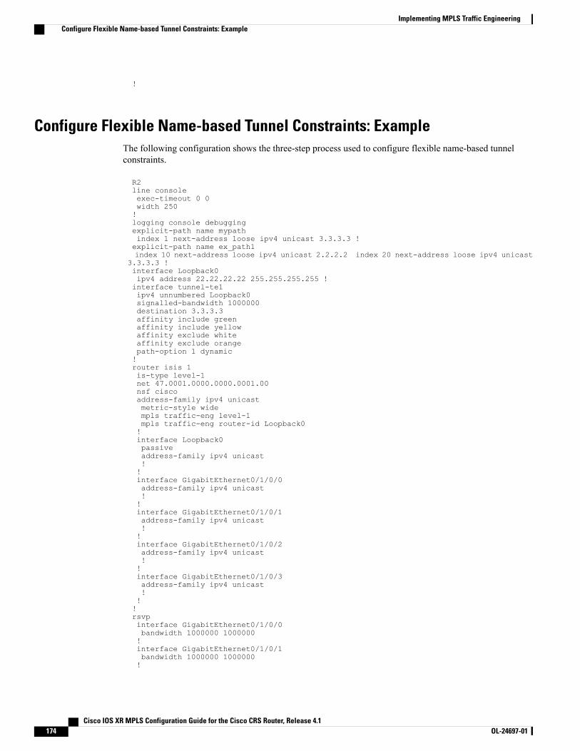
!
Configure Flexible Name-based Tunnel Constraints: ExampleThe following configuration shows the three-step process used to configure flexible name-based tunnelconstraints.
R2line consoleexec-timeout 0 0width 250!logging console debuggingexplicit-path name mypathindex 1 next-address loose ipv4 unicast 3.3.3.3 !explicit-path name ex_path1index 10 next-address loose ipv4 unicast 2.2.2.2 index 20 next-address loose ipv4 unicast
3.3.3.3 !interface Loopback0ipv4 address 22.22.22.22 255.255.255.255 !interface tunnel-te1ipv4 unnumbered Loopback0signalled-bandwidth 1000000destination 3.3.3.3affinity include greenaffinity include yellowaffinity exclude whiteaffinity exclude orangepath-option 1 dynamic!router isis 1is-type level-1net 47.0001.0000.0000.0001.00nsf ciscoaddress-family ipv4 unicastmetric-style widempls traffic-eng level-1mpls traffic-eng router-id Loopback0!interface Loopback0passiveaddress-family ipv4 unicast!!interface GigabitEthernet0/1/0/0address-family ipv4 unicast!!interface GigabitEthernet0/1/0/1address-family ipv4 unicast!!interface GigabitEthernet0/1/0/2address-family ipv4 unicast!!interface GigabitEthernet0/1/0/3address-family ipv4 unicast!!!rsvpinterface GigabitEthernet0/1/0/0bandwidth 1000000 1000000!interface GigabitEthernet0/1/0/1bandwidth 1000000 1000000!
Cisco IOS XR MPLS Configuration Guide for the Cisco CRS Router, Release 4.1174 OL-24697-01
Implementing MPLS Traffic EngineeringConfigure Flexible Name-based Tunnel Constraints: Example
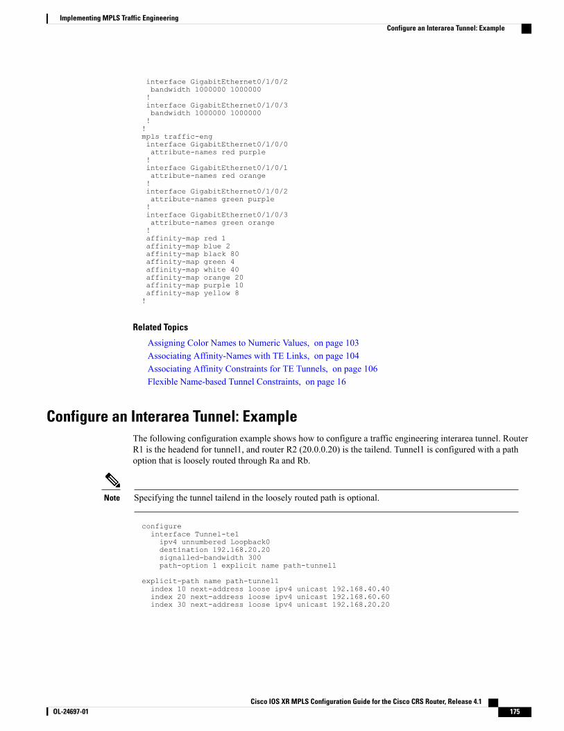
interface GigabitEthernet0/1/0/2bandwidth 1000000 1000000!interface GigabitEthernet0/1/0/3bandwidth 1000000 1000000!!mpls traffic-enginterface GigabitEthernet0/1/0/0attribute-names red purple!interface GigabitEthernet0/1/0/1attribute-names red orange!interface GigabitEthernet0/1/0/2attribute-names green purple!interface GigabitEthernet0/1/0/3attribute-names green orange!affinity-map red 1affinity-map blue 2affinity-map black 80affinity-map green 4affinity-map white 40affinity-map orange 20affinity-map purple 10affinity-map yellow 8!
Related Topics
Assigning Color Names to Numeric Values, on page 103Associating Affinity-Names with TE Links, on page 104Associating Affinity Constraints for TE Tunnels, on page 106Flexible Name-based Tunnel Constraints, on page 16
Configure an Interarea Tunnel: ExampleThe following configuration example shows how to configure a traffic engineering interarea tunnel. RouterR1 is the headend for tunnel1, and router R2 (20.0.0.20) is the tailend. Tunnel1 is configured with a pathoption that is loosely routed through Ra and Rb.
Specifying the tunnel tailend in the loosely routed path is optional.Note
configureinterface Tunnel-te1ipv4 unnumbered Loopback0destination 192.168.20.20signalled-bandwidth 300path-option 1 explicit name path-tunnel1
explicit-path name path-tunnel1index 10 next-address loose ipv4 unicast 192.168.40.40index 20 next-address loose ipv4 unicast 192.168.60.60index 30 next-address loose ipv4 unicast 192.168.20.20
Cisco IOS XR MPLS Configuration Guide for the Cisco CRS Router, Release 4.1 OL-24697-01 175
Implementing MPLS Traffic EngineeringConfigure an Interarea Tunnel: Example
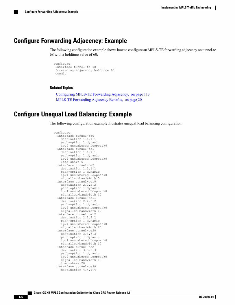
Configure Forwarding Adjacency: ExampleThe following configuration example shows how to configure anMPLS-TE forwarding adjacency on tunnel-te68 with a holdtime value of 60:
configureinterface tunnel-te 68forwarding-adjacency holdtime 60commit
Related Topics
Configuring MPLS-TE Forwarding Adjacency, on page 113MPLS-TE Forwarding Adjacency Benefits, on page 20
Configure Unequal Load Balancing: ExampleThe following configuration example illustrates unequal load balancing configuration:
configureinterface tunnel-te0destination 1.1.1.1path-option 1 dynamicipv4 unnumbered Loopback0
interface tunnel-te1destination 1.1.1.1path-option 1 dynamicipv4 unnumbered Loopback0load-share 5
interface tunnel-te2destination 1.1.1.1path-option 1 dynamicipv4 unnumbered Loopback0signalled-bandwidth 5
interface tunnel-te10destination 2.2.2.2path-option 1 dynamicipv4 unnumbered Loopback0signalled-bandwidth 10
interface tunnel-te11destination 2.2.2.2path-option 1 dynamicipv4 unnumbered Loopback0signalled-bandwidth 10
interface tunnel-te12destination 2.2.2.2path-option 1 dynamicipv4 unnumbered Loopback0signalled-bandwidth 20
interface tunnel-te20destination 3.3.3.3path-option 1 dynamicipv4 unnumbered Loopback0signalled-bandwidth 10
interface tunnel-te21destination 3.3.3.3path-option 1 dynamicipv4 unnumbered Loopback0signalled-bandwidth 10load-share 20
interface tunnel-te30destination 4.4.4.4
Cisco IOS XR MPLS Configuration Guide for the Cisco CRS Router, Release 4.1176 OL-24697-01
Implementing MPLS Traffic EngineeringConfigure Forwarding Adjacency: Example
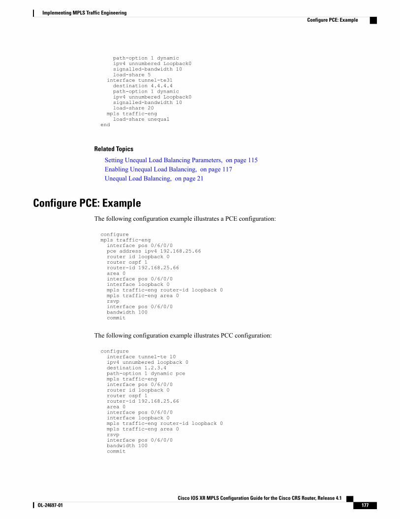
path-option 1 dynamicipv4 unnumbered Loopback0signalled-bandwidth 10load-share 5
interface tunnel-te31destination 4.4.4.4path-option 1 dynamicipv4 unnumbered Loopback0signalled-bandwidth 10load-share 20
mpls traffic-engload-share unequal
end
Related Topics
Setting Unequal Load Balancing Parameters, on page 115Enabling Unequal Load Balancing, on page 117Unequal Load Balancing, on page 21
Configure PCE: ExampleThe following configuration example illustrates a PCE configuration:
configurempls traffic-enginterface pos 0/6/0/0pce address ipv4 192.168.25.66router id loopback 0router ospf 1router-id 192.168.25.66area 0interface pos 0/6/0/0interface loopback 0mpls traffic-eng router-id loopback 0mpls traffic-eng area 0rsvpinterface pos 0/6/0/0bandwidth 100commit
The following configuration example illustrates PCC configuration:
configureinterface tunnel-te 10ipv4 unnumbered loopback 0destination 1.2.3.4path-option 1 dynamic pcempls traffic-enginterface pos 0/6/0/0router id loopback 0router ospf 1router-id 192.168.25.66area 0interface pos 0/6/0/0interface loopback 0mpls traffic-eng router-id loopback 0mpls traffic-eng area 0rsvpinterface pos 0/6/0/0bandwidth 100commit
Cisco IOS XR MPLS Configuration Guide for the Cisco CRS Router, Release 4.1 OL-24697-01 177
Implementing MPLS Traffic EngineeringConfigure PCE: Example
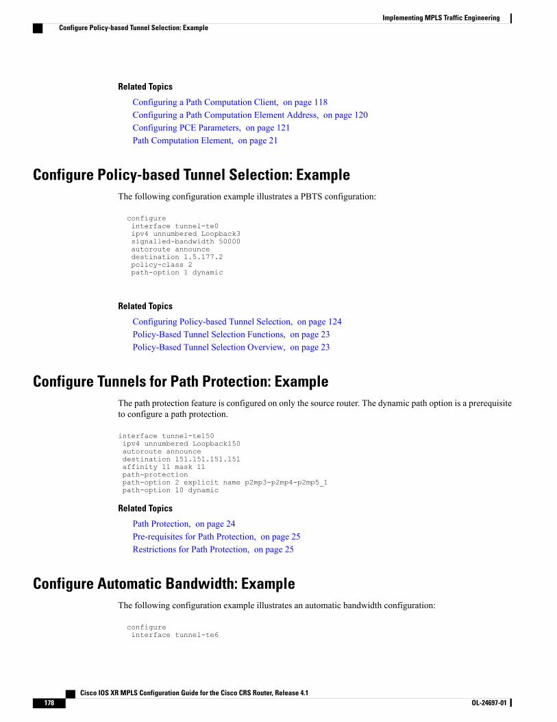
Related Topics
Configuring a Path Computation Client, on page 118Configuring a Path Computation Element Address, on page 120Configuring PCE Parameters, on page 121Path Computation Element, on page 21
Configure Policy-based Tunnel Selection: ExampleThe following configuration example illustrates a PBTS configuration:
configureinterface tunnel-te0ipv4 unnumbered Loopback3signalled-bandwidth 50000autoroute announcedestination 1.5.177.2policy-class 2path-option 1 dynamic
Related Topics
Configuring Policy-based Tunnel Selection, on page 124Policy-Based Tunnel Selection Functions, on page 23Policy-Based Tunnel Selection Overview, on page 23
Configure Tunnels for Path Protection: ExampleThe path protection feature is configured on only the source router. The dynamic path option is a prerequisiteto configure a path protection.
interface tunnel-te150ipv4 unnumbered Loopback150autoroute announcedestination 151.151.151.151affinity 11 mask 11path-protectionpath-option 2 explicit name p2mp3-p2mp4-p2mp5_1path-option 10 dynamic
Related Topics
Path Protection, on page 24Pre-requisites for Path Protection, on page 25Restrictions for Path Protection, on page 25
Configure Automatic Bandwidth: ExampleThe following configuration example illustrates an automatic bandwidth configuration:
configureinterface tunnel-te6
Cisco IOS XR MPLS Configuration Guide for the Cisco CRS Router, Release 4.1178 OL-24697-01
Implementing MPLS Traffic EngineeringConfigure Policy-based Tunnel Selection: Example
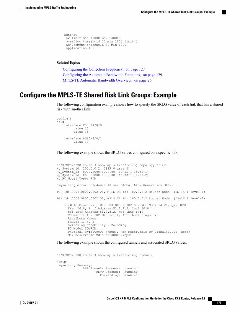
auto-bwbw-limit min 10000 max 500000overflow threshold 50 min 1000 limit 3adjustment-threshold 20 min 1000application 180
Related Topics
Configuring the Collection Frequency, on page 127Configuring the Automatic Bandwidth Functions, on page 129MPLS-TE Automatic Bandwidth Overview, on page 26
Configure the MPLS-TE Shared Risk Link Groups: ExampleThe following configuration example shows how to specify the SRLG value of each link that has a sharedrisk with another link:
config tsrlg
interface POS0/4/0/0value 10value 11
|interface POS0/4/0/1
value 10|
The following example shows the SRLG values configured on a specific link.
RP/0/RP0/CPU0:router# show mpls traffic-eng topology briefMy_System_id: 100.0.0.2 (OSPF 0 area 0)My_System_id: 0000.0000.0002.00 (IS-IS 1 level-1)My_System_id: 0000.0000.0002.00 (IS-IS 1 level-2)My_BC_Model_Type: RDM
Signalling error holddown: 10 sec Global Link Generation 389225
IGP Id: 0000.0000.0002.00, MPLS TE Id: 100.0.0.2 Router Node (IS-IS 1 level-1)
IGP Id: 0000.0000.0002.00, MPLS TE Id: 100.0.0.2 Router Node (IS-IS 1 level-2)
Link[1]:Broadcast, DR:0000.0000.0002.07, Nbr Node Id:21, gen:389193Frag Id:0, Intf Address:51.2.3.2, Intf Id:0Nbr Intf Address:51.2.3.2, Nbr Intf Id:0TE Metric:10, IGP Metric:10, Attribute Flags:0x0Attribute Names:SRLGs: 1, 4, 5Switching Capability:, Encoding:BC Model ID:RDMPhysical BW:1000000 (kbps), Max Reservable BW Global:10000 (kbps)Max Reservable BW Sub:10000 (kbps)
The following example shows the configured tunnels and associated SRLG values.
RP/0/RP0/CPU0:router# show mpls traffic-eng tunnels
<snip>Signalling Summary:
LSP Tunnels Process: runningRSVP Process: runningForwarding: enabled
Cisco IOS XR MPLS Configuration Guide for the Cisco CRS Router, Release 4.1 OL-24697-01 179
Implementing MPLS Traffic EngineeringConfigure the MPLS-TE Shared Risk Link Groups: Example
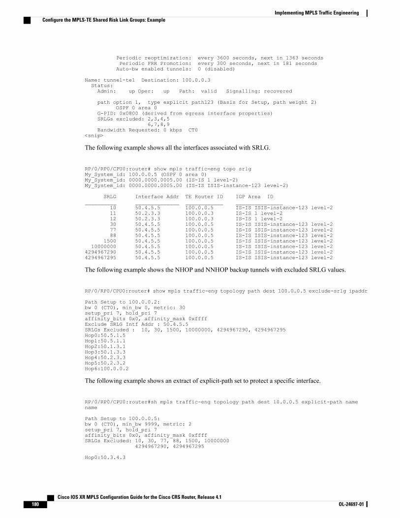
Periodic reoptimization: every 3600 seconds, next in 1363 secondsPeriodic FRR Promotion: every 300 seconds, next in 181 secondsAuto-bw enabled tunnels: 0 (disabled)
Name: tunnel-te1 Destination: 100.0.0.3Status:Admin: up Oper: up Path: valid Signalling: recovered
path option 1, type explicit path123 (Basis for Setup, path weight 2)OSPF 0 area 0
G-PID: 0x0800 (derived from egress interface properties)SRLGs excluded: 2,3,4,5
6,7,8,9Bandwidth Requested: 0 kbps CT0
<snip>
The following example shows all the interfaces associated with SRLG.
RP/0/RP0/CPU0:router# show mpls traffic-eng topo srlgMy_System_id: 100.0.0.5 (OSPF 0 area 0)My_System_id: 0000.0000.0005.00 (IS-IS 1 level-2)My_System_id: 0000.0000.0005.00 (IS-IS ISIS-instance-123 level-2)
SRLG Interface Addr TE Router ID IGP Area ID__________ ______________ ____________ _______________
10 50.4.5.5 100.0.0.5 IS-IS ISIS-instance-123 level-211 50.2.3.3 100.0.0.3 IS-IS 1 level-212 50.2.3.3 100.0.0.3 IS-IS 1 level-230 50.4.5.5 100.0.0.5 IS-IS ISIS-instance-123 level-277 50.4.5.5 100.0.0.5 IS-IS ISIS-instance-123 level-288 50.4.5.5 100.0.0.5 IS-IS ISIS-instance-123 level-2
1500 50.4.5.5 100.0.0.5 IS-IS ISIS-instance-123 level-210000000 50.4.5.5 100.0.0.5 IS-IS ISIS-instance-123 level-2
4294967290 50.4.5.5 100.0.0.5 IS-IS ISIS-instance-123 level-24294967295 50.4.5.5 100.0.0.5 IS-IS ISIS-instance-123 level-2
The following example shows the NHOP and NNHOP backup tunnels with excluded SRLG values.
RP/0/RP0/CPU0:router# show mpls traffic-eng topology path dest 100.0.0.5 exclude-srlg ipaddr
Path Setup to 100.0.0.2:bw 0 (CT0), min_bw 0, metric: 30setup_pri 7, hold_pri 7affinity_bits 0x0, affinity_mask 0xffffExclude SRLG Intf Addr : 50.4.5.5SRLGs Excluded : 10, 30, 1500, 10000000, 4294967290, 4294967295Hop0:50.5.1.5Hop1:50.5.1.1Hop2:50.1.3.1Hop3:50.1.3.3Hop4:50.2.3.3Hop5:50.2.3.2Hop6:100.0.0.2
The following example shows an extract of explicit-path set to protect a specific interface.
RP/0/RP0/CPU0:router#sh mpls traffic-eng topology path dest 10.0.0.5 explicit-path namename
Path Setup to 100.0.0.5:bw 0 (CT0), min_bw 9999, metric: 2setup_pri 7, hold_pri 7affinity_bits 0x0, affinity_mask 0xffffSRLGs Excluded: 10, 30, 77, 88, 1500, 10000000
4294967290, 4294967295
Hop0:50.3.4.3
Cisco IOS XR MPLS Configuration Guide for the Cisco CRS Router, Release 4.1180 OL-24697-01
Implementing MPLS Traffic EngineeringConfigure the MPLS-TE Shared Risk Link Groups: Example
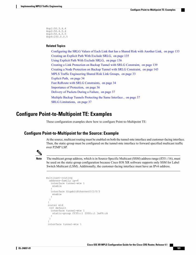
Hop1:50.3.4.4Hop2:50.4.5.4Hop3:50.4.5.5Hop4:100.0.0.5
Related Topics
Configuring the SRLG Values of Each Link that has a Shared Risk with Another Link, on page 133Creating an Explicit Path With Exclude SRLG, on page 135Using Explicit Path With Exclude SRLG, on page 136Creating a Link Protection on Backup Tunnel with SRLG Constraint, on page 139Creating a Node Protection on Backup Tunnel with SRLG Constraint, on page 143MPLS Traffic Engineering Shared Risk Link Groups, on page 33Explicit Path, on page 34Fast ReRoute with SRLG Constraints, on page 34Importance of Protection, on page 36Delivery of Packets During a Failure, on page 37
Multiple Backup Tunnels Protecting the Same Interface , on page 37SRLG Limitations, on page 37
Configure Point-to-Multipoint TE: ExamplesThese configuration examples show how to configure Point-to-Multipoint TE:
Configure Point-to-Multipoint for the Source: ExampleAt the source, multicast routingmust be enabled on both the tunnel-mte interface and customer-facing interface.Then, the static-group must be configured on the tunnel-mte interface to forward specified multicast trafficover P2MP LSP.
The multicast group address, which is in Source-Specific Multicast (SSM) address range (ff35::/16), mustbe used on the static-group configuration because Cisco IOS XR software supports only SSM for LabelSwitch Multicast (LSM). Additionally, the customer-facing interface must have an IPv6 address.
Note
multicast-routingaddress-family ipv6interface tunnel-mte 1enable!interface GigabitEthernet0/2/0/3enable!!!router mldvrf defaultinterface tunnel-mte 1static-group ff35::1 2000::1 3eFF::A!!!interface tunnel-mte 1
Cisco IOS XR MPLS Configuration Guide for the Cisco CRS Router, Release 4.1 OL-24697-01 181
Implementing MPLS Traffic EngineeringConfigure Point-to-Multipoint TE: Examples
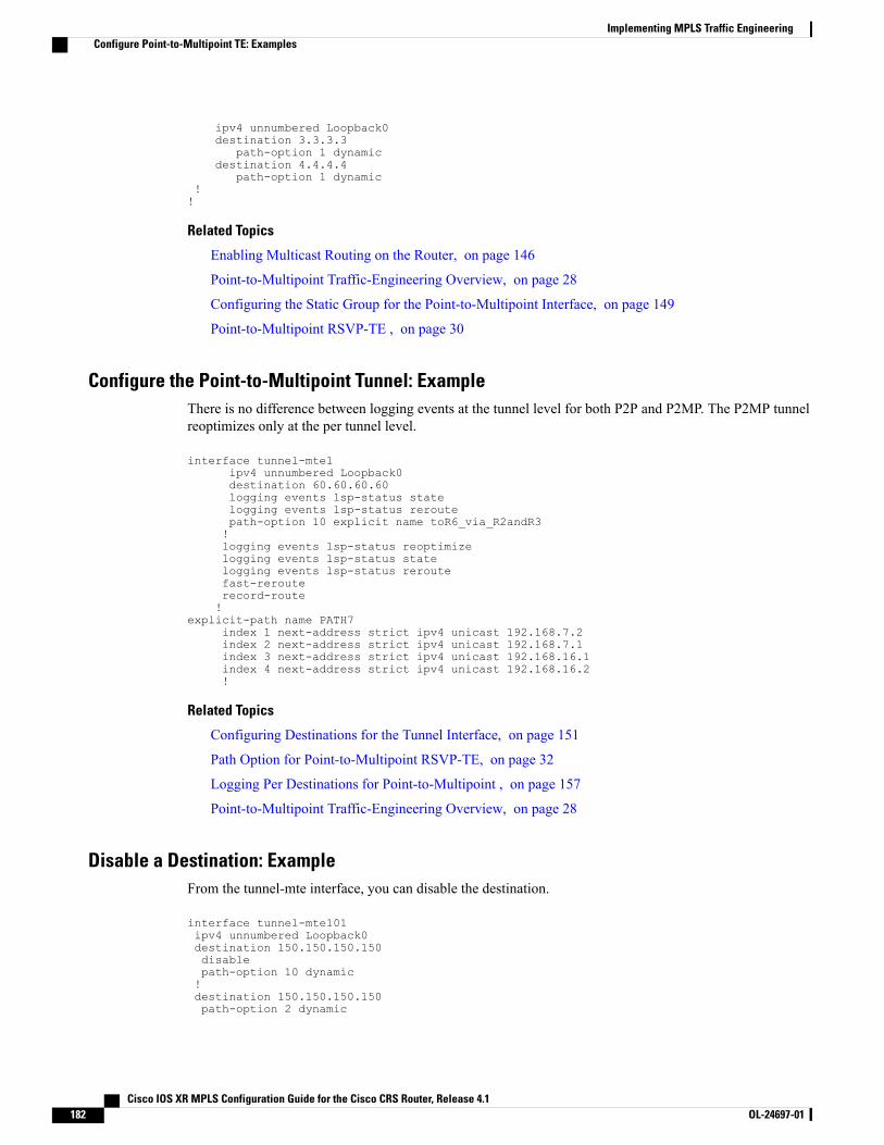
ipv4 unnumbered Loopback0destination 3.3.3.3
path-option 1 dynamicdestination 4.4.4.4
path-option 1 dynamic!!
Related Topics
Enabling Multicast Routing on the Router, on page 146
Point-to-Multipoint Traffic-Engineering Overview, on page 28
Configuring the Static Group for the Point-to-Multipoint Interface, on page 149
Point-to-Multipoint RSVP-TE , on page 30
Configure the Point-to-Multipoint Tunnel: ExampleThere is no difference between logging events at the tunnel level for both P2P and P2MP. The P2MP tunnelreoptimizes only at the per tunnel level.
interface tunnel-mte1ipv4 unnumbered Loopback0destination 60.60.60.60logging events lsp-status statelogging events lsp-status reroutepath-option 10 explicit name toR6_via_R2andR3!logging events lsp-status reoptimizelogging events lsp-status statelogging events lsp-status reroutefast-rerouterecord-route!
explicit-path name PATH7index 1 next-address strict ipv4 unicast 192.168.7.2index 2 next-address strict ipv4 unicast 192.168.7.1index 3 next-address strict ipv4 unicast 192.168.16.1index 4 next-address strict ipv4 unicast 192.168.16.2!
Related Topics
Configuring Destinations for the Tunnel Interface, on page 151
Path Option for Point-to-Multipoint RSVP-TE, on page 32
Logging Per Destinations for Point-to-Multipoint , on page 157
Point-to-Multipoint Traffic-Engineering Overview, on page 28
Disable a Destination: ExampleFrom the tunnel-mte interface, you can disable the destination.
interface tunnel-mte101ipv4 unnumbered Loopback0destination 150.150.150.150disablepath-option 10 dynamic!destination 150.150.150.150path-option 2 dynamic
Cisco IOS XR MPLS Configuration Guide for the Cisco CRS Router, Release 4.1182 OL-24697-01
Implementing MPLS Traffic EngineeringConfigure Point-to-Multipoint TE: Examples
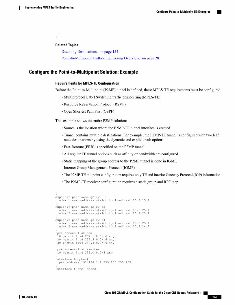
!!
Related Topics
Disabling Destinations, on page 154
Point-to-Multipoint Traffic-Engineering Overview, on page 28
Configure the Point-to-Multipoint Solution: Example
Requirements for MPLS-TE Configuration
Before the Point-to-Multipoint (P2MP) tunnel is defined, these MPLS-TE requirements must be configured:
• Multiprotocol Label Switching traffic engineering (MPLS-TE)
• Resource ReSerVation Protocol (RSVP)
• Open Shortest Path First (OSPF)
This example shows the entire P2MP solution:
• Source is the location where the P2MP-TE tunnel interface is created.
• Tunnel contains multiple destinations. For example, the P2MP-TE tunnel is configured with two leafnode destinations by using the dynamic and explicit path options.
• Fast-Reroute (FRR) is specified on the P2MP tunnel.
• All regular TE tunnel options such as affinity or bandwidth are configured.
• Static mapping of the group address to the P2MP tunnel is done in IGMP.
Internet Group Management Protocol (IGMP).
• The P2MP-TEmidpoint configuration requires only TE and Interior Gateway Protocol (IGP) information.
• The P2MP-TE receiver configuration requires a static group and RPF map.
!explicit-path name g2-r2-r1index 1 next-address strict ipv4 unicast 10.2.15.1!explicit-path name g2-r2-r3index 1 next-address strict ipv4 unicast 10.2.25.1index 2 next-address strict ipv4 unicast 10.2.23.2!explicit-path name g2-r2-r4index 1 next-address strict ipv4 unicast 10.2.25.1index 2 next-address strict ipv4 unicast 10.2.24.2!ipv4 access-list ssm10 permit ipv4 232.1.0.0/16 any20 permit ipv4 232.3.0.0/16 any30 permit ipv4 232.4.0.0/16 any!ipv4 access-list ssm-test10 permit ipv4 235.0.0.0/8 any!interface Loopback0ipv4 address 192.168.1.2 255.255.255.255!interface tunnel-mte221
Cisco IOS XR MPLS Configuration Guide for the Cisco CRS Router, Release 4.1 OL-24697-01 183
Implementing MPLS Traffic EngineeringConfigure Point-to-Multipoint TE: Examples
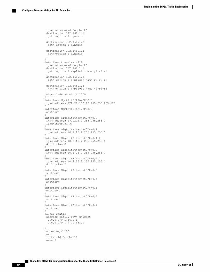
ipv4 unnumbered Loopback0destination 192.168.1.1path-option 1 dynamic!destination 192.168.1.3path-option 1 dynamic!destination 192.168.1.4path-option 1 dynamic!!interface tunnel-mte222ipv4 unnumbered Loopback0destination 192.168.1.1path-option 1 explicit name g2-r2-r1!destination 192.168.1.3path-option 1 explicit name g2-r2-r3!destination 192.168.1.4path-option 1 explicit name g2-r2-r4!signalled-bandwidth 1000!interface MgmtEth0/RP0/CPU0/0ipv4 address 172.20.163.12 255.255.255.128!interface MgmtEth0/RP1/CPU0/0shutdown!interface GigabitEthernet0/0/0/0ipv4 address 172.2.1.2 255.255.255.0load-interval 30!interface GigabitEthernet0/0/0/1ipv4 address 10.1.15.2 255.255.255.0!interface GigabitEthernet0/0/0/1.2ipv4 address 10.2.15.2 255.255.255.0dot1q vlan 2!interface GigabitEthernet0/0/0/2ipv4 address 10.1.25.2 255.255.255.0!interface GigabitEthernet0/0/0/2.2ipv4 address 10.2.25.2 255.255.255.0dot1q vlan 2!interface GigabitEthernet0/0/0/3shutdown!interface GigabitEthernet0/0/0/4shutdown!interface GigabitEthernet0/0/0/5shutdown!interface GigabitEthernet0/0/0/6shutdown!interface GigabitEthernet0/0/0/7shutdown!router staticaddress-family ipv4 unicast0.0.0.0/0 1.56.0.10.0.0.0/0 172.20.163.1!!router ospf 100nsrrouter-id Loopback0area 0
Cisco IOS XR MPLS Configuration Guide for the Cisco CRS Router, Release 4.1184 OL-24697-01
Implementing MPLS Traffic EngineeringConfigure Point-to-Multipoint TE: Examples
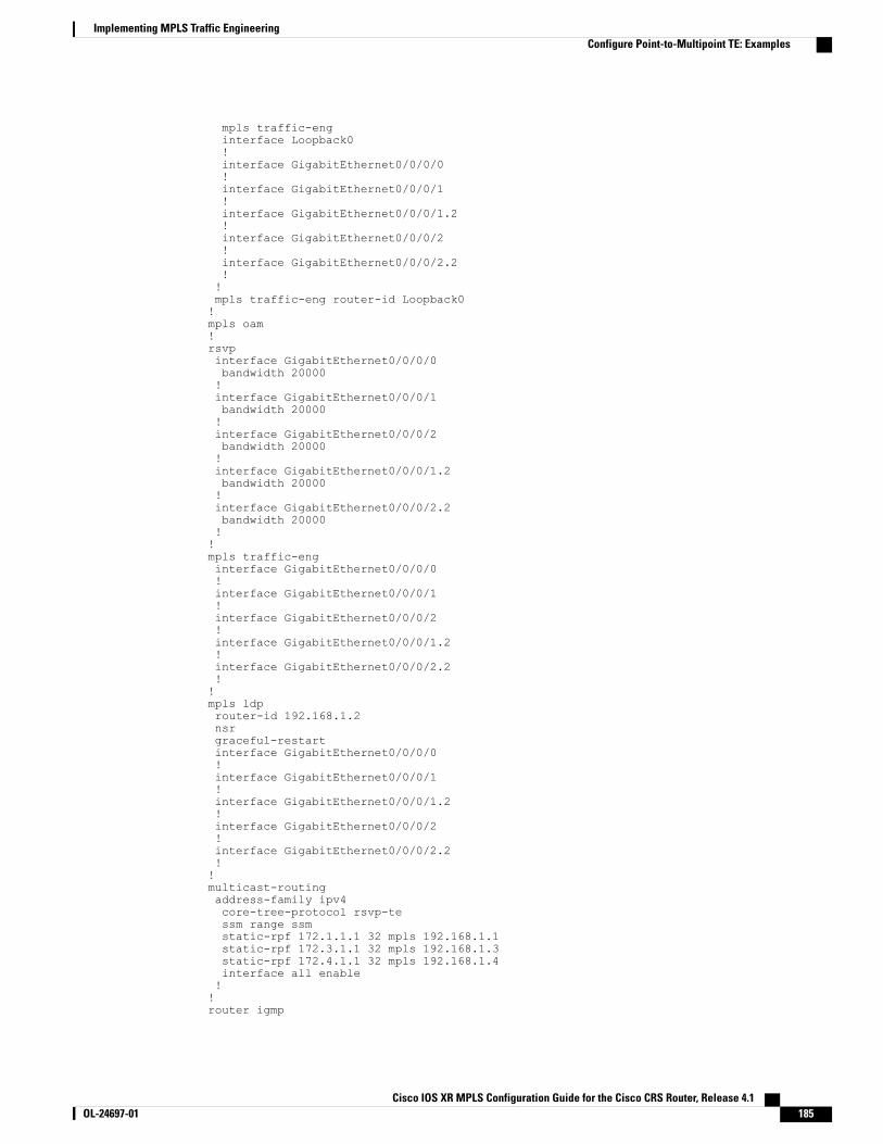
mpls traffic-enginterface Loopback0!interface GigabitEthernet0/0/0/0!interface GigabitEthernet0/0/0/1!interface GigabitEthernet0/0/0/1.2!interface GigabitEthernet0/0/0/2!interface GigabitEthernet0/0/0/2.2!!mpls traffic-eng router-id Loopback0!mpls oam!rsvpinterface GigabitEthernet0/0/0/0bandwidth 20000!interface GigabitEthernet0/0/0/1bandwidth 20000!interface GigabitEthernet0/0/0/2bandwidth 20000!interface GigabitEthernet0/0/0/1.2bandwidth 20000!interface GigabitEthernet0/0/0/2.2bandwidth 20000!!mpls traffic-enginterface GigabitEthernet0/0/0/0!interface GigabitEthernet0/0/0/1!interface GigabitEthernet0/0/0/2!interface GigabitEthernet0/0/0/1.2!interface GigabitEthernet0/0/0/2.2!!mpls ldprouter-id 192.168.1.2nsrgraceful-restartinterface GigabitEthernet0/0/0/0!interface GigabitEthernet0/0/0/1!interface GigabitEthernet0/0/0/1.2!interface GigabitEthernet0/0/0/2!interface GigabitEthernet0/0/0/2.2!!multicast-routingaddress-family ipv4core-tree-protocol rsvp-tessm range ssmstatic-rpf 172.1.1.1 32 mpls 192.168.1.1static-rpf 172.3.1.1 32 mpls 192.168.1.3static-rpf 172.4.1.1 32 mpls 192.168.1.4interface all enable!!router igmp
Cisco IOS XR MPLS Configuration Guide for the Cisco CRS Router, Release 4.1 OL-24697-01 185
Implementing MPLS Traffic EngineeringConfigure Point-to-Multipoint TE: Examples
!interface tunnel-mte221static-group 232.2.2.1 172.2.1.1!interface tunnel-mte222static-group 232.2.2.2 172.2.1.1!interface GigabitEthernet0/0/0/0static-group 232.1.2.1 172.1.1.1static-group 232.1.2.2 172.1.1.1static-group 232.3.2.1 172.3.1.1static-group 232.3.2.2 172.3.1.1static-group 232.4.2.1 172.4.1.1static-group 232.4.2.2 172.4.1.1!!end
Related Topics
Enabling Multicast Routing on the Router, on page 146
Point-to-Multipoint Traffic-Engineering Overview, on page 28
Configuring the Static Group for the Point-to-Multipoint Interface, on page 149
Point-to-Multipoint RSVP-TE , on page 30
Configuring Destinations for the Tunnel Interface, on page 151
Path Option for Point-to-Multipoint RSVP-TE, on page 32
Logging Per Destinations for Point-to-Multipoint , on page 157
Point-to-Multipoint Traffic-Engineering Overview, on page 28
Additional ReferencesFor additional information related to implementing MPLS-TE, refer to the following references:
Related Documents
Document TitleRelated Topic
MPLS Traffic Engineering Commands on Cisco IOSXR Software module in Cisco IOS XR MPLSCommand Reference for the Cisco CRS Router
MPLS-TE commands
Cisco IOS XR Getting Started Guide for theCisco CRS Router
Getting started material
Configuring AAA Services on Cisco IOS XR Softwaremodule of Cisco IOS XR System SecurityConfiguration Guide for the Cisco CRS Router
Information about user groups and task IDs
Cisco IOS XR MPLS Configuration Guide for the Cisco CRS Router, Release 4.1186 OL-24697-01
Implementing MPLS Traffic EngineeringAdditional References
Standards
TitleStandards
—Technical Assistance Center (TAC) home page,containing 30,000 pages of searchable technicalcontent, including links to products, technologies,solutions, technical tips, and tools. RegisteredCisco.com users can log in from this page to accesseven more content.
MIBs
MIBs LinkMIBs
To locate and download MIBs using Cisco IOS XRsoftware, use the Cisco MIB Locator found at thefollowingURL and choose a platform under the CiscoAccess Products menu: http://cisco.com/public/sw-center/netmgmt/cmtk/mibs.shtml
—
RFCs
TitleRFCs
Protocol Extensions for Support of Diffserv-awareMPLS Traffic Engineering, F. Le Faucheur, Ed. June2005.
(Format: TXT=79265 bytes) (Status: PROPOSEDSTANDARD)
RFC 4124
Maximum Allocation Bandwidth Constraints Modelfor Diffserv-aware MPLS Traffic Engineering, F. LeFaucheur, W. Lai. June 2005.
(Format: TXT=22585 bytes) (Status:EXPERIMENTAL)
RFC 4125
Russian Dolls Bandwidth Constraints Model forDiffserv-aware MPLS Traffic Engineering, F. LeFaucheur, Ed. June 2005.
(Format: TXT=23694 bytes) (Status:EXPERIMENTAL)
RFC 4127
Cisco IOS XR MPLS Configuration Guide for the Cisco CRS Router, Release 4.1 OL-24697-01 187
Implementing MPLS Traffic EngineeringAdditional References
Technical Assistance
LinkDescription
http://www.cisco.com/techsupportThe Cisco Technical Support website containsthousands of pages of searchable technical content,including links to products, technologies, solutions,technical tips, and tools. Registered Cisco.com userscan log in from this page to access evenmore content.
Cisco IOS XR MPLS Configuration Guide for the Cisco CRS Router, Release 4.1188 OL-24697-01
Implementing MPLS Traffic EngineeringAdditional References
Recommended


![[MPLS Configuration Guide] - D-Link Academyacademy.dlink.com/temp/exam_Issue/230/MPLS Configuration Guide… · MPLS Configuration Guide Multiprotocol Label Switching (MPLS) MPLS](https://img.pdfslide.us/doc/110x75/5a815ac47f8b9ada388cfeea/mpls-configuration-guide-d-link-configuration-guidempls-configuration-guide.jpg)