Embed Size (px)
Citation preview
1
Understanding MPLS OAM capabilities to troubleshoot MPLS Networks
Mukhtiar A. Shaikh ([email protected])Moiz Moizuddin ([email protected])
222
Agenda
• MPLS Overview• Existing Ping/Trace Capabilities • LSP Ping/Trace
–Theory of Operation
–MPLS Echo Packet
–Configuration and Troubleshooting Using LSP Ping/Trace
•LSP Ping
•LSP Trace
–AToM VCCV
• Summary
333
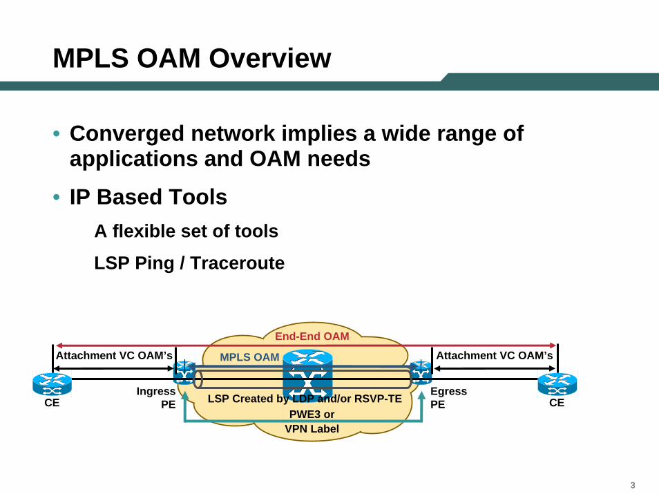
MPLS OAM Overview
IngressPE CECE
EgressPE
MPLS OAM
End-End OAM
Attachment VC OAM’s Attachment VC OAM’s
PWE3 orVPN Label
LSP Created by LDP and/or RSVP-TE
• Converged network implies a wide range of applications and OAM needs
• IP Based ToolsA flexible set of tools
LSP Ping / Traceroute
444
Agenda
• MPLS Overview• Existing Ping/Trace Capabilities • LSP Ping/Trace
–Theory of Operation
–MPLS Echo Packet
–Configuration and Troubleshooting Using LSP Ping/Trace
•LSP Ping
•LSP Trace
–AToM VCCV
• Summary
555
IP Ping
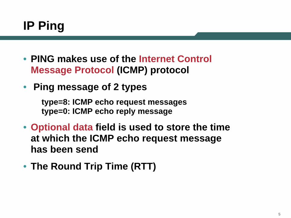
• PING makes use of the Internet Control Message Protocol (ICMP) protocol
• Ping message of 2 typestype=8: ICMP echo request messagestype=0: ICMP echo reply message
• Optional data field is used to store the time at which the ICMP echo request message has been send
• The Round Trip Time (RTT)
666
IP Traceroute
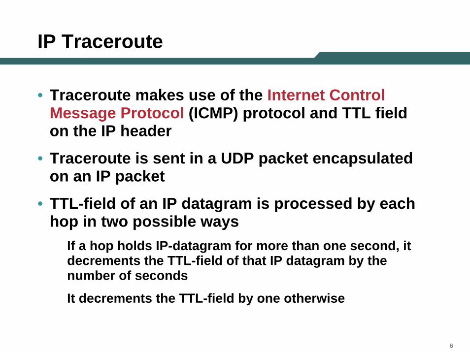
• Traceroute makes use of the Internet Control Message Protocol (ICMP) protocol and TTL field on the IP header
• Traceroute is sent in a UDP packet encapsulated on an IP packet
• TTL-field of an IP datagram is processed by each hop in two possible ways
If a hop holds IP-datagram for more than one second, it decrements the TTL-field of that IP datagram by the number of seconds
It decrements the TTL-field by one otherwise
777
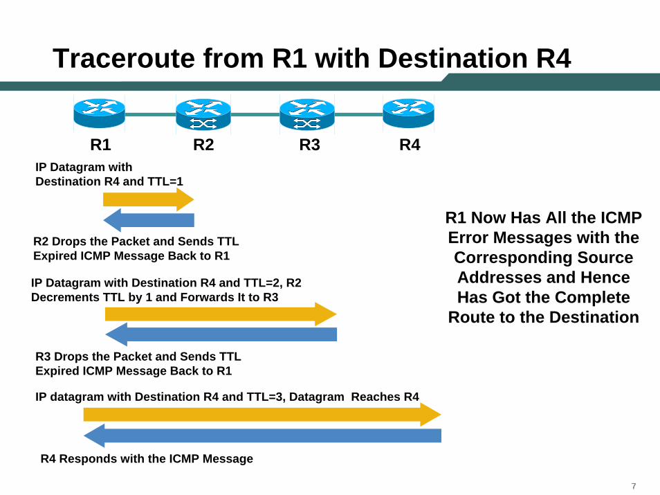
Traceroute from R1 with Destination R4
R1 R4R2 R3IP Datagram with Destination R4 and TTL=1
R2 Drops the Packet and Sends TTL Expired ICMP Message Back to R1
IP Datagram with Destination R4 and TTL=2, R2 Decrements TTL by 1 and Forwards It to R3
R3 Drops the Packet and Sends TTL Expired ICMP Message Back to R1
R1 Now Has All the ICMP Error Messages with the Corresponding Source Addresses and Hence Has Got the Complete
Route to the Destination
IP datagram with Destination R4 and TTL=3, Datagram Reaches R4
R4 Responds with the ICMP Message
888
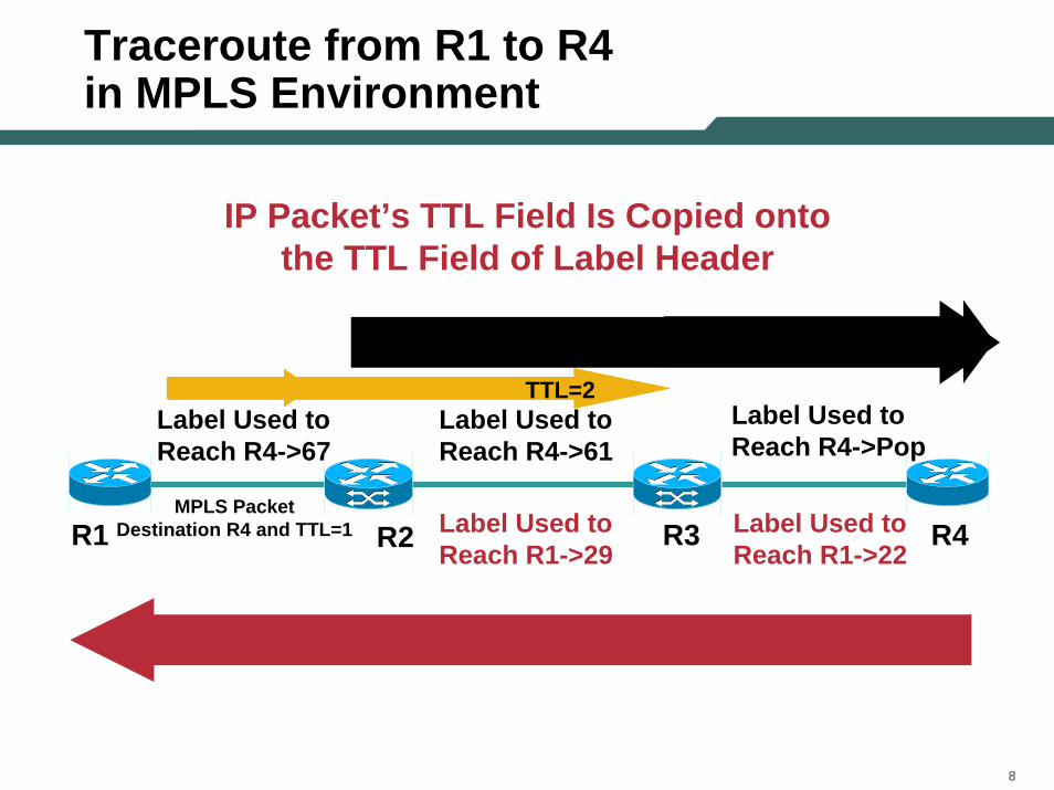
Traceroute from R1 to R4 in MPLS Environment
IP Packet’s TTL Field Is Copied onto the TTL Field of Label Header
R1 R4R2 R3
Label Used to Reach R4->67
Label Used to Reach R4->61
Label Used to Reach R1->22
Label Used to Reach R1->29
MPLS Packet Destination R4 and TTL=1
Label Used to Reach R4->Pop
TTL=2
999
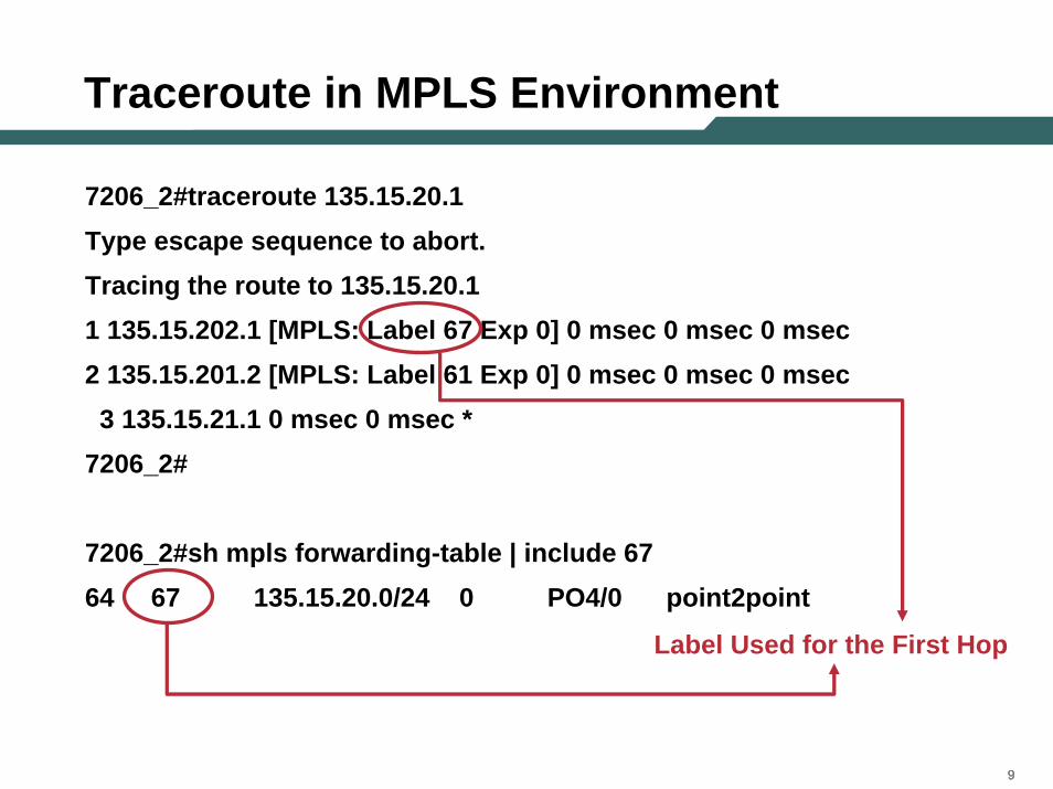
Traceroute in MPLS Environment
7206_2#traceroute 135.15.20.1Type escape sequence to abort.Tracing the route to 135.15.20.11 135.15.202.1 [MPLS: Label 67 Exp 0] 0 msec 0 msec 0 msec2 135.15.201.2 [MPLS: Label 61 Exp 0] 0 msec 0 msec 0 msec3 135.15.21.1 0 msec 0 msec *
7206_2#
7206_2#sh mpls forwarding-table | include 6764 67 135.15.20.0/24 0 PO4/0 point2point
Label Used for the First Hop
101010
VRF-Aware Ping/Traceroute
• VPN/VRF routing table used to route the ICMP packet
• The IP datagram uses the MP BGP label and then the LDP label
• PE generates and sends the packet• Packet goes into the VRF• Penultimate P hop packet, will pop label and the
PE router then routes it to the destination • PE generates ICMP echo reply and sends the
packet back to local PE adding MP BGP and LDP label on top of it
111111
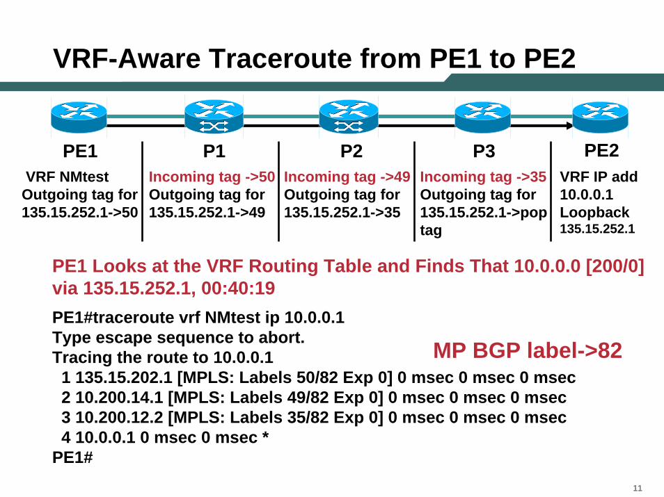
VRF-Aware Traceroute from PE1 to PE2
PE1 P3P1 P2 PE2VRF IP add 10.0.0.1Loopback 135.15.252.1
VRF NMtestOutgoing tag for 135.15.252.1->50
Incoming tag ->50 Outgoing tag for 135.15.252.1->49
Incoming tag ->49 Outgoing tag for 135.15.252.1->35
Incoming tag ->35 Outgoing tag for 135.15.252.1->pop tag
PE1 Looks at the VRF Routing Table and Finds That 10.0.0.0 [200/0] via 135.15.252.1, 00:40:19PE1#traceroute vrf NMtest ip 10.0.0.1Type escape sequence to abort.Tracing the route to 10.0.0.11 135.15.202.1 [MPLS: Labels 50/82 Exp 0] 0 msec 0 msec 0 msec2 10.200.14.1 [MPLS: Labels 49/82 Exp 0] 0 msec 0 msec 0 msec3 10.200.12.2 [MPLS: Labels 35/82 Exp 0] 0 msec 0 msec 0 msec4 10.0.0.1 0 msec 0 msec *
PE1#
MP BGP label->82
121212
Agenda
• MPLS Overview• Existing Ping/Trace Capabilities • LSP Ping/Trace
–Theory of Operation
–MPLS Echo Packet
–Configuration and Troubleshooting Using LSP Ping/Trace
•LSP Ping
•LSP Trace
–AToM VCCV
• Summary
131313
LSP Ping
• LSP Ping/Trace, like the traditional IP Ping, is based on echo request and echo reply
• But LSP Ping/Trace doesn’t use an ICMP packet
• Rather LSP Ping/Trace relies on IPv4(or IPv6) UDP packets with port 3503; UDP packets received with port 3503 are either an MPLS echo or an MPLS echo-reply
141414
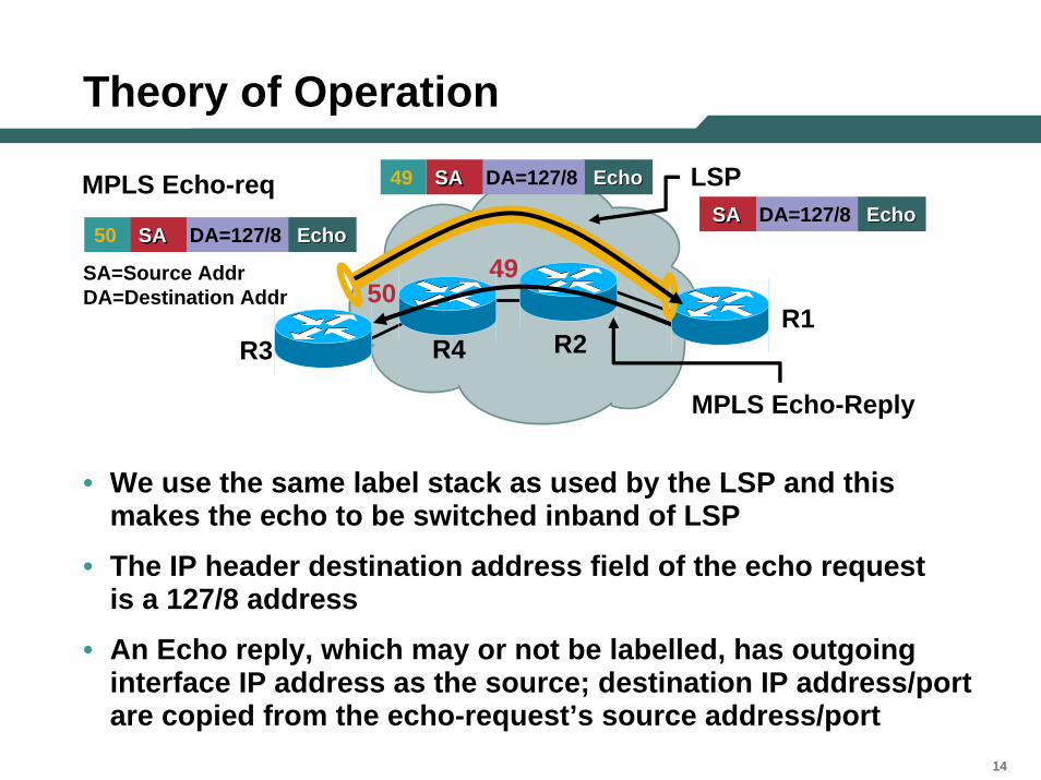
Theory of Operation
R3R1
MPLS Echo-req
49SA=Source AddrDA=Destination Addr
EchoEcho50 SASA DA=127/8
50
MPLS Echo-Reply
EchoEcho49 SASA DA=127/8
EchoEchoSASA DA=127/8
LSP
R2R4
• We use the same label stack as used by the LSP and this makes the echo to be switched inband of LSP
• The IP header destination address field of the echo request is a 127/8 address
• An Echo reply, which may or not be labelled, has outgoing interface IP address as the source; destination IP address/port are copied from the echo-request’s source address/port
151515
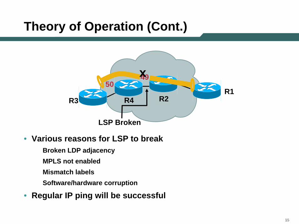
Theory of Operation (Cont.)
LSP Broken
4950
R3 R2R4
xR1
• Various reasons for LSP to breakBroken LDP adjacencyMPLS not enabledMismatch labelsSoftware/hardware corruption
• Regular IP ping will be successful
161616
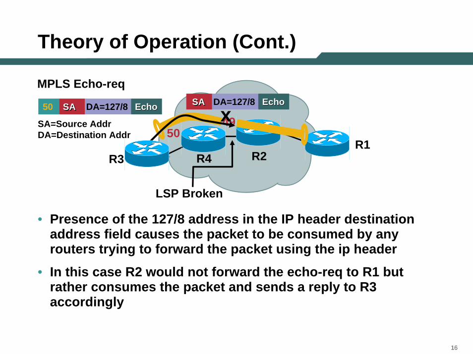
Theory of Operation (Cont.)
R3
LSP Broken
MPLS Echo-req
49SA=Source AddrDA=Destination Addr
EchoEcho50 SASA DA=127/8 EchoEchoSASA DA=127/8
50
R2R4
xR1
• Presence of the 127/8 address in the IP header destination address field causes the packet to be consumed by any routers trying to forward the packet using the ip header
• In this case R2 would not forward the echo-req to R1 but rather consumes the packet and sends a reply to R3 accordingly
171717
Agenda
• MPLS Overview• Existing Ping/Trace Capabilities • LSP Ping/Trace
–Theory of Operation
–MPLS Echo Packet
–Configuration and Troubleshooting Using LSP Ping/Trace
•LSP Ping
•LSP Trace
–AToM VCCV
• Summary
181818
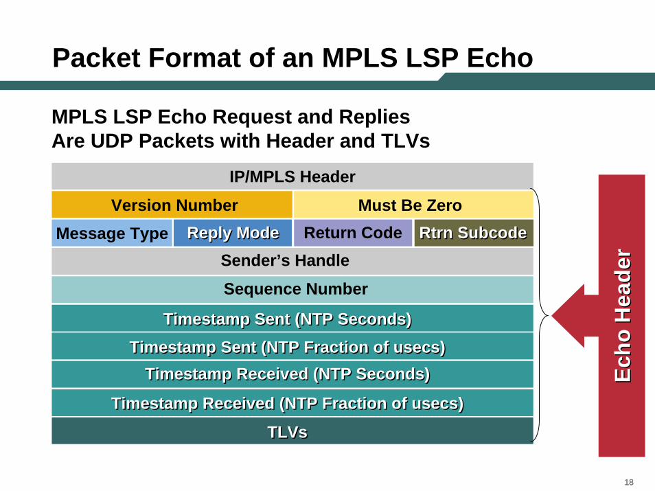
Packet Format of an MPLS LSP Echo
MPLS LSP Echo Request and Replies Are UDP Packets with Header and TLVs
TLVsTLVs
Timestamp Sent (NTP Seconds)Timestamp Sent (NTP Seconds)
Timestamp Sent (NTP Fraction of usecs)Timestamp Sent (NTP Fraction of usecs)Timestamp Received (NTP Seconds)Timestamp Received (NTP Seconds)
Timestamp Received (NTP Fraction of usecs)Timestamp Received (NTP Fraction of usecs)
Sequence Number
Sender’s Handle Message Type Reply ModeReply Mode Return Code Rtrn Subcode Rtrn Subcode
Version Number Must Be Zero
IP/MPLS Header
Echo
Hea
der
Echo
Hea
der
191919
Packet Format of anMPLS LSP Echo (Cont.)
TLVsTLVs
Timestamp Sent (NTP Seconds)Timestamp Sent (NTP Seconds)Timestamp Sent (NTP Fraction of usecs)Timestamp Sent (NTP Fraction of usecs)
Timestamp Received (NTP Seconds)Timestamp Received (NTP Seconds)Timestamp Received (NTP Fraction of usecs)Timestamp Received (NTP Fraction of usecs)
Sequence Number Sender’s Handle
Reply ModeReply Mode Return Code Rtrn Subcode Rtrn Subcode Must Be Zero
IP/MPLS Header
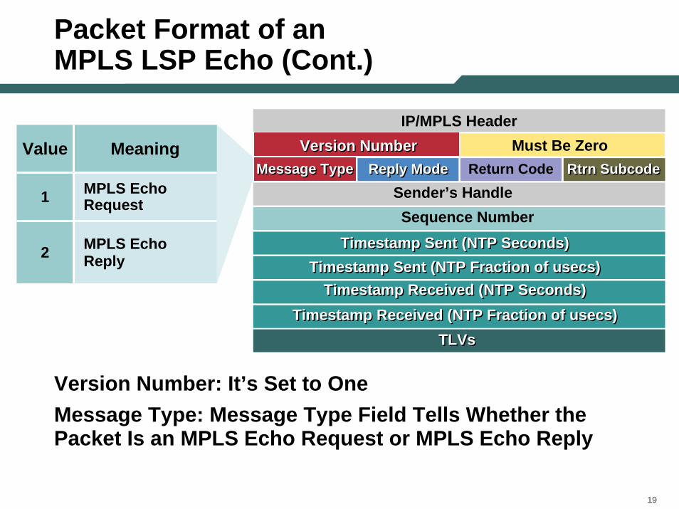
Version Number: It’s Set to One Message Type: Message Type Field Tells Whether the Packet Is an MPLS Echo Request or MPLS Echo Reply
Value Meaning
1 MPLS Echo Request
2 MPLS EchoReply
Message TypeVersion Number Version Number Version Number
Message TypeMessage Type
202020
Packet Format of an MPLS LSP Echo (Cont.)
TLVsTLVs
Timestamp Sent (NTP Seconds)Timestamp Sent (NTP Seconds)Timestamp Sent (NTP Fraction of usecs)Timestamp Sent (NTP Fraction of usecs)
Timestamp Received (NTP Seconds)Timestamp Received (NTP Seconds)Timestamp Received (NTP Fraction of usecs)Timestamp Received (NTP Fraction of usecs)
Sequence Number Sender’s Handle
Message Type Return Code Rtrn Subcode Rtrn Subcode Version Number Must Be Zero
IP/MPLS Header
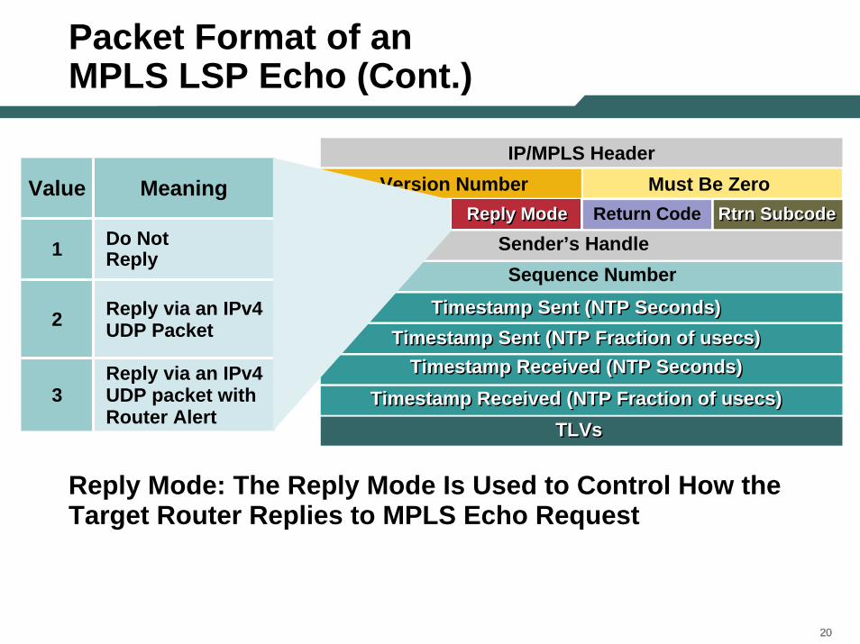
Reply Mode: The Reply Mode Is Used to Control How the Target Router Replies to MPLS Echo Request
Value Meaning
1 Do Not Reply
2 Reply via an IPv4 UDP Packet
3Reply via an IPv4 UDP packet with Router Alert
Reply ModeReply Mode
212121
Return Code
TLVsTLVs
Timestamp Sent (NTP Seconds)Timestamp Sent (NTP Seconds)Timestamp Sent (NTP Fraction of usecs)Timestamp Sent (NTP Fraction of usecs)
Timestamp Received (NTP Seconds)Timestamp Received (NTP Seconds)Timestamp Received (NTP Fraction of usecs)Timestamp Received (NTP Fraction of usecs)
Sequence Number Sender’s Handle
Message Type Reply ModeReply Mode Return Code Rtrn Subcode Rtrn Subcode Version Number Must Be Zero
IP/MPLS Header
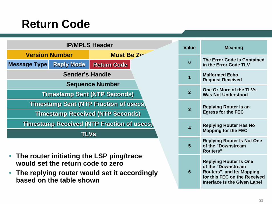
• The router initiating the LSP ping/trace would set the return code to zero
• The replying router would set it accordingly based on the table shown
Value Meaning
0 The Error Code Is Contained in the Error Code TLV
1 Malformed Echo Request Received
4 Replying Router Has No Mapping for the FEC
5Replying Router Is Not One of the "Downstream Routers"
2 One Or More of the TLVs Was Not Understood
3 Replying Router Is an Egress for the FEC
6
Replying Router Is One of the "Downstream Routers", and Its Mapping for this FEC on the Received Interface Is the Given Label
Return CodeReturn Code
222222
Sender Handle
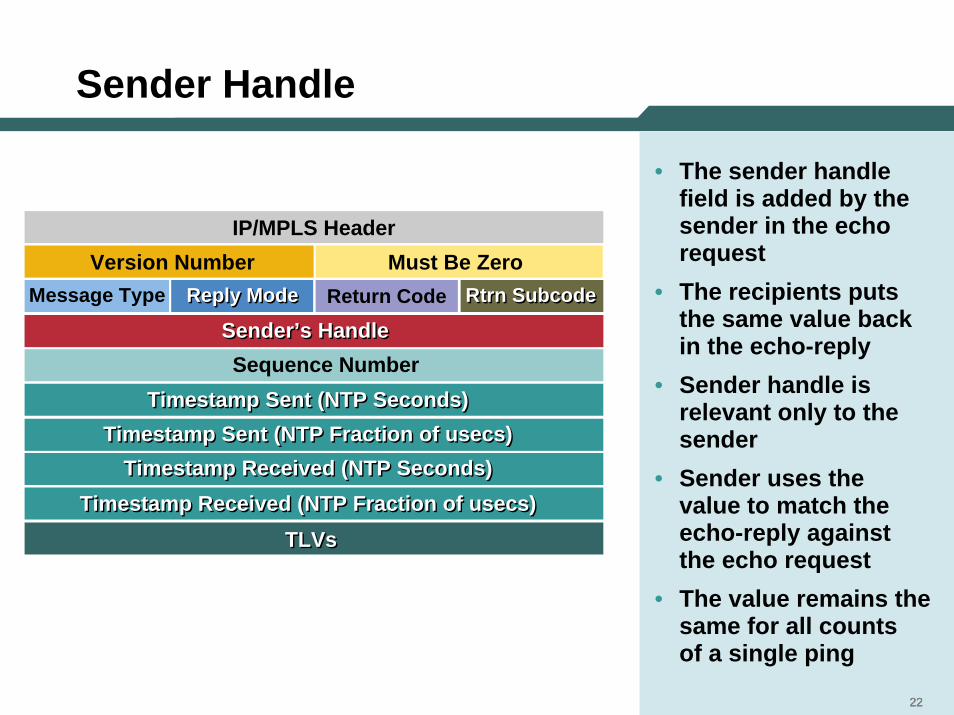
• The sender handle field is added by the sender in the echo request
• The recipients puts the same value back in the echo-reply
• Sender handle is relevant only to the sender
• Sender uses the value to match the echo-reply against the echo request
• The value remains the same for all counts of a single ping
TLVsTLVs
Timestamp Sent (NTP Seconds)Timestamp Sent (NTP Seconds)Timestamp Sent (NTP Fraction of usecs)Timestamp Sent (NTP Fraction of usecs)
Timestamp Received (NTP Seconds)Timestamp Received (NTP Seconds)Timestamp Received (NTP Fraction of usecs)Timestamp Received (NTP Fraction of usecs)
Sequence Number Sender’s Handle
Message Type Reply ModeReply Mode Return Code Rtrn Subcode Rtrn Subcode Version Number Must Be Zero
IP/MPLS Header
Sender’s Handle Sender’s Handle
222222
232323
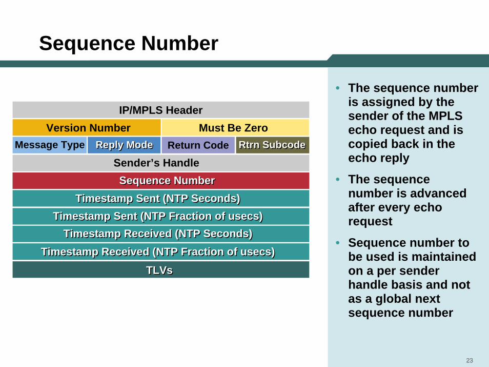
Sequence Number
• The sequence number is assigned by the sender of the MPLS echo request and is copied back in the echo reply
• The sequence number is advanced after every echo request
• Sequence number to be used is maintained on a per sender handle basis and not as a global next sequence number
TLVsTLVs
Timestamp Sent (NTP Seconds)Timestamp Sent (NTP Seconds)Timestamp Sent (NTP Fraction of usecs)Timestamp Sent (NTP Fraction of usecs)
Timestamp Received (NTP Seconds)Timestamp Received (NTP Seconds)Timestamp Received (NTP Fraction of usecs)Timestamp Received (NTP Fraction of usecs)
Sequence Number Sender’s Handle
Message Type Reply ModeReply Mode Return Code Rtrn Subcode Rtrn Subcode Version Number Must Be Zero
IP/MPLS Header
Sequence Number Sequence Number
232323
242424
Sender Handle/Seq Numbers
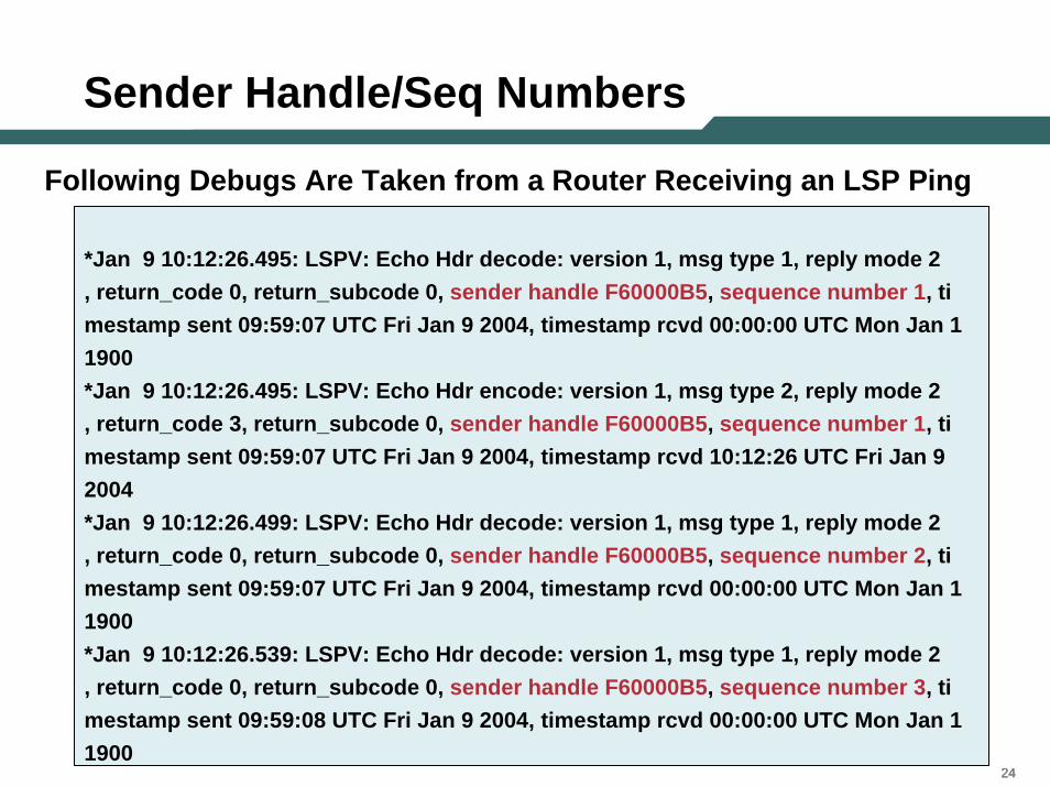
*Jan 9 10:12:26.495: LSPV: Echo Hdr decode: version 1, msg type 1, reply mode 2, return_code 0, return_subcode 0, sender handle F60000B5, sequence number 1, timestamp sent 09:59:07 UTC Fri Jan 9 2004, timestamp rcvd 00:00:00 UTC Mon Jan 11900*Jan 9 10:12:26.495: LSPV: Echo Hdr encode: version 1, msg type 2, reply mode 2, return_code 3, return_subcode 0, sender handle F60000B5, sequence number 1, timestamp sent 09:59:07 UTC Fri Jan 9 2004, timestamp rcvd 10:12:26 UTC Fri Jan 92004*Jan 9 10:12:26.499: LSPV: Echo Hdr decode: version 1, msg type 1, reply mode 2, return_code 0, return_subcode 0, sender handle F60000B5, sequence number 2, timestamp sent 09:59:07 UTC Fri Jan 9 2004, timestamp rcvd 00:00:00 UTC Mon Jan 11900*Jan 9 10:12:26.539: LSPV: Echo Hdr decode: version 1, msg type 1, reply mode 2, return_code 0, return_subcode 0, sender handle F60000B5, sequence number 3, timestamp sent 09:59:08 UTC Fri Jan 9 2004, timestamp rcvd 00:00:00 UTC Mon Jan 11900
Following Debugs Are Taken from a Router Receiving an LSP Ping
252525
Timestamp
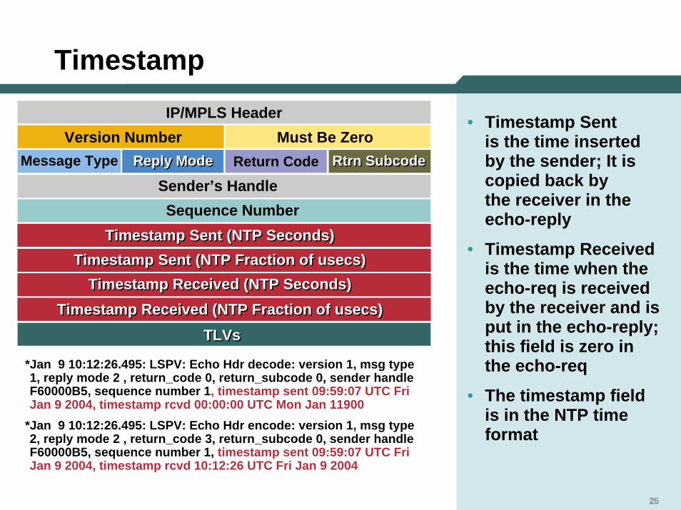
• Timestamp Sent is the time inserted by the sender; It is copied back by the receiver in the echo-reply
• Timestamp Received is the time when the echo-req is received by the receiver and is put in the echo-reply; this field is zero in the echo-req
• The timestamp field is in the NTP time format
*Jan 9 10:12:26.495: LSPV: Echo Hdr decode: version 1, msg type1, reply mode 2 , return_code 0, return_subcode 0, sender handleF60000B5, sequence number 1, timestamp sent 09:59:07 UTC Fri Jan 9 2004, timestamp rcvd 00:00:00 UTC Mon Jan 11900
*Jan 9 10:12:26.495: LSPV: Echo Hdr encode: version 1, msg type2, reply mode 2 , return_code 3, return_subcode 0, sender handleF60000B5, sequence number 1, timestamp sent 09:59:07 UTC Fri Jan 9 2004, timestamp rcvd 10:12:26 UTC Fri Jan 9 2004
TLVsTLVs
Timestamp Sent (NTP Seconds)Timestamp Sent (NTP Seconds)Timestamp Sent (NTP Fraction of usecs)Timestamp Sent (NTP Fraction of usecs)
Timestamp Received (NTP Seconds)Timestamp Received (NTP Seconds)Timestamp Received (NTP Fraction of usecs)Timestamp Received (NTP Fraction of usecs)
Sequence Number Sender’s Handle
Message Type Reply ModeReply Mode Return Code Rtrn Subcode Rtrn Subcode Version Number Must Be Zero
IP/MPLS Header
252525
Timestamp Sent (NTP Seconds)Timestamp Sent (NTP Seconds)Timestamp Sent (NTP Fraction of usecs)Timestamp Sent (NTP Fraction of usecs)
Timestamp Received (NTP Seconds)Timestamp Received (NTP Seconds)Timestamp Received (NTP Fraction of usecs)Timestamp Received (NTP Fraction of usecs)
26
LSP Ping/Trace TLVs
272727
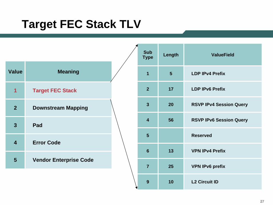
Target FEC Stack TLV
Sub Type Length ValueField
1
2
3
4
5
6
7
9
5 LDP IPv4 Prefix
17 LDP IPv6 Prefix
20 RSVP IPv4 Session Query
56 RSVP IPv6 Session Query
Reserved
13 VPN IPv4 Prefix
25 VPN IPv6 prefix
10 L2 Circuit ID
272727
Value Meaning
1 Target FEC Stack
2 Downstream Mapping
3 Pad
4 Error Code
5 Vendor Enterprise Code
282828
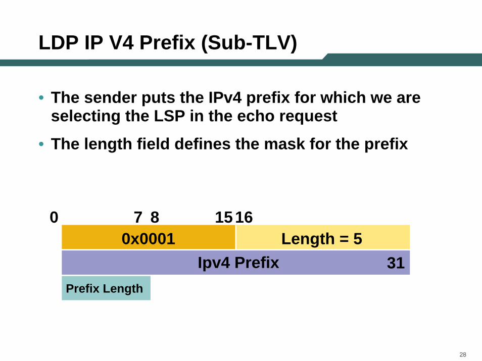
LDP IP V4 Prefix (Sub-TLV)
• The sender puts the IPv4 prefix for which we are selecting the LSP in the echo request
• The length field defines the mask for the prefix
0x0001 Length = 5
Prefix Length
Ipv4 Prefix
15160 7 8
31
292929
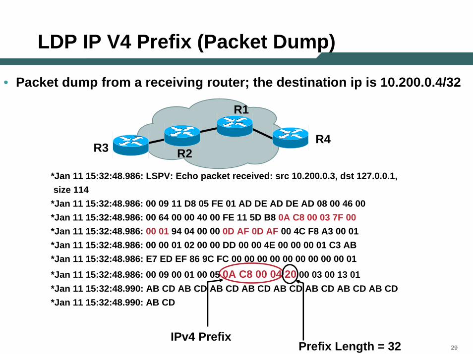
LDP IP V4 Prefix (Packet Dump)
• Packet dump from a receiving router; the destination ip is 10.200.0.4/32
IPv4 PrefixPrefix Length = 32
*Jan 11 15:32:48.986: LSPV: Echo packet received: src 10.200.0.3, dst 127.0.0.1,size 114
*Jan 11 15:32:48.986: 00 09 11 D8 05 FE 01 AD DE AD DE AD 08 00 46 00*Jan 11 15:32:48.986: 00 64 00 00 40 00 FE 11 5D B8 0A C8 00 03 7F 00*Jan 11 15:32:48.986: 00 01 94 04 00 00 0D AF 0D AF 00 4C F8 A3 00 01*Jan 11 15:32:48.986: 00 00 01 02 00 00 DD 00 00 4E 00 00 00 01 C3 AB*Jan 11 15:32:48.986: E7 ED EF 86 9C FC 00 00 00 00 00 00 00 00 00 01*Jan 11 15:32:48.986: 00 09 00 01 00 05 0A C8 00 04 20 00 03 00 13 01*Jan 11 15:32:48.990: AB CD AB CD AB CD AB CD AB CD AB CD AB CD AB CD*Jan 11 15:32:48.990: AB CD
R1
R2R4
R3
303030
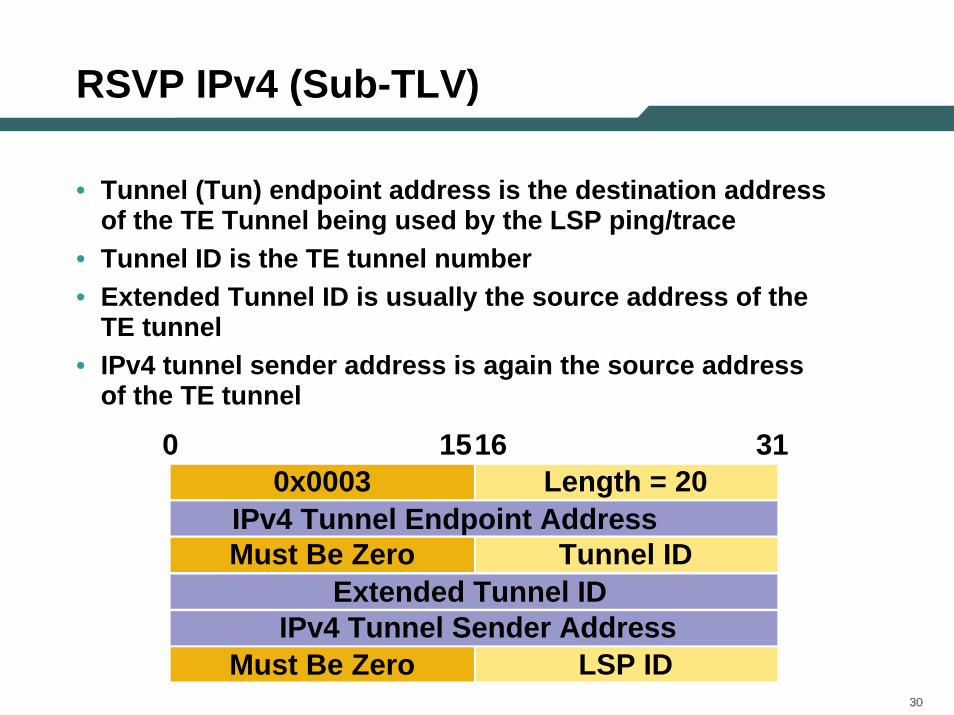
RSVP IPv4 (Sub-TLV)
• Tunnel (Tun) endpoint address is the destination address of the TE Tunnel being used by the LSP ping/trace
• Tunnel ID is the TE tunnel number• Extended Tunnel ID is usually the source address of the
TE tunnel• IPv4 tunnel sender address is again the source address
of the TE tunnel
0x0003 Length = 20 IPv4 Tunnel Endpoint Address
0 1516 31
Must Be Zero Tunnel ID Extended Tunnel ID
Must Be Zero LSP ID IPv4 Tunnel Sender Address
313131
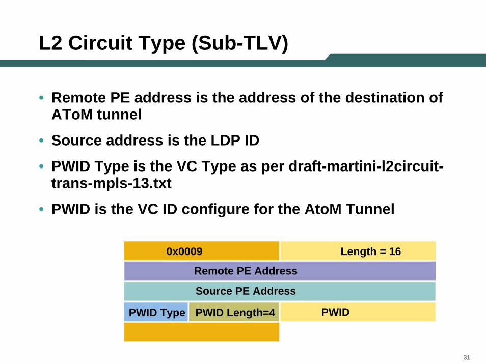
L2 Circuit Type (Sub-TLV)
• Remote PE address is the address of the destination of AToM tunnel
• Source address is the LDP ID
• PWID Type is the VC Type as per draft-martini-l2circuit-trans-mpls-13.txt
• PWID is the VC ID configure for the AtoM Tunnel
0x0009 Length = 16
PWID Type PWID Length=4
Remote PE Address
Source PE Address
PWID
323232
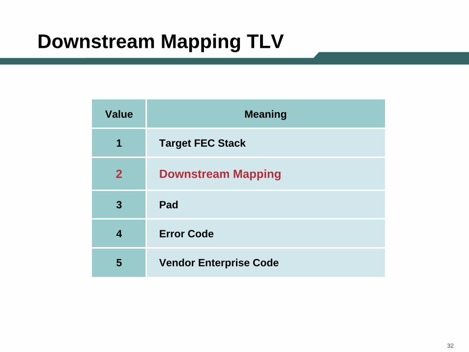
Downstream Mapping TLV
Value Meaning
1 Target FEC Stack
2 Downstream Mapping
3 Pad
4 Error Code
5 Vendor Enterprise Code
333333
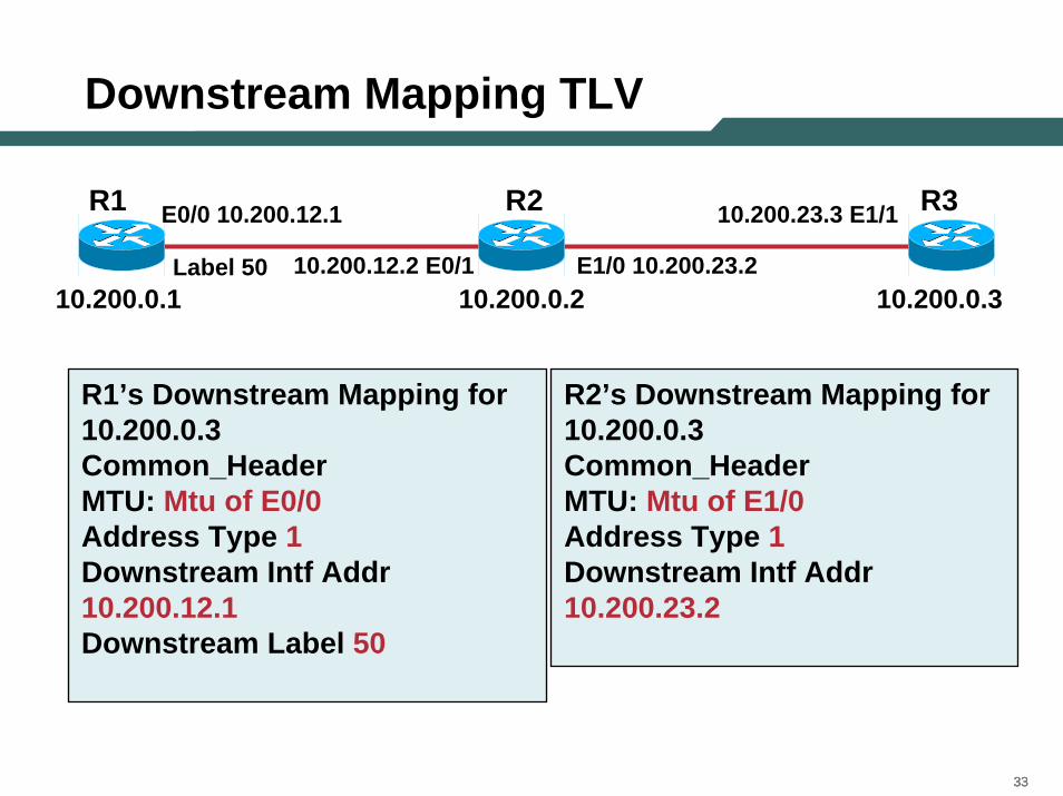
Downstream Mapping TLV
R2 R3R1 E0/0 10.200.12.1
10.200.12.2 E0/1
10.200.23.3 E1/1
E1/0 10.200.23.210.200.0.2 10.200.0.310.200.0.1
Label 50
R1’s Downstream Mapping for 10.200.0.3 Common_HeaderMTU: Mtu of E0/0Address Type 1Downstream Intf Addr 10.200.12.1Downstream Label 50
R2’s Downstream Mapping for 10.200.0.3 Common_HeaderMTU: Mtu of E1/0Address Type 1Downstream Intf Addr 10.200.23.2
343434
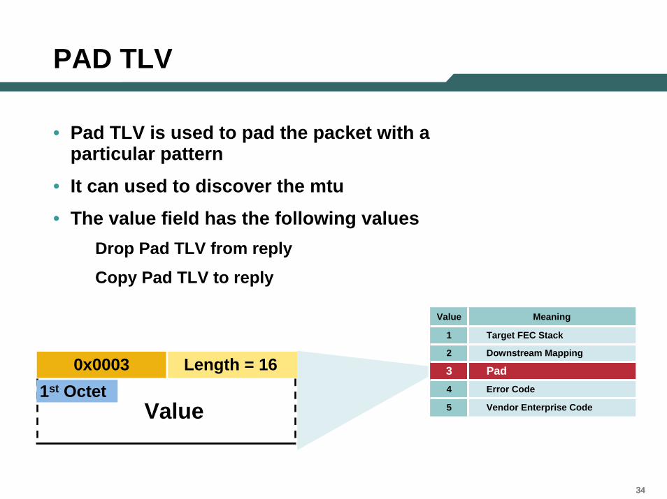
PAD TLV
• Pad TLV is used to pad the packet with a particular pattern
• It can used to discover the mtu
• The value field has the following valuesDrop Pad TLV from reply
Copy Pad TLV to reply
0x0003 Length = 16 1st Octet
Value
Pad3Downstream Mapping2
Vendor Enterprise Code 5
Error Code4
Target FEC Stack1
MeaningValue
353535
Agenda
• MPLS Overview• Existing Ping/Trace Capabilities • LSP Ping/Trace
–Theory of Operation
–MPLS Echo Packet
–Configuration and Troubleshooting Using LSP Ping/Trace
•LSP Ping
•LSP Trace
–AToM VCCV
• Summary
363636
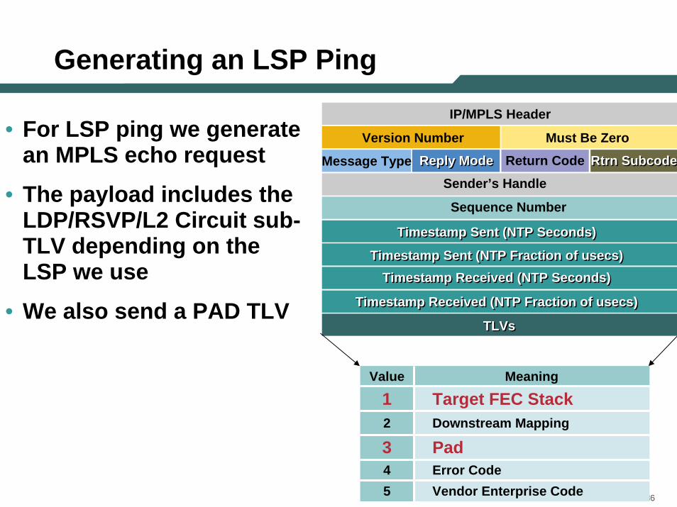
Generating an LSP Ping
• For LSP ping we generate an MPLS echo request
• The payload includes the LDP/RSVP/L2 Circuit sub-TLV depending on the LSP we use
• We also send a PAD TLV
Value Meaning
1 Target FEC Stack2 Downstream Mapping
3 Pad4 Error Code5 Vendor Enterprise Code
TLVsTLVs
Timestamp Sent (NTP Seconds)Timestamp Sent (NTP Seconds)
Timestamp Sent (NTP Fraction of usecs)Timestamp Sent (NTP Fraction of usecs)
Timestamp Received (NTP Seconds)Timestamp Received (NTP Seconds)
Timestamp Received (NTP Fraction of usecs)Timestamp Received (NTP Fraction of usecs)
Sequence Number
Sender’s Handle Message Type Reply ModeReply Mode Return Code Rtrn Subcode Rtrn Subcode
Version Number Must Be Zero
IP/MPLS Header
373737
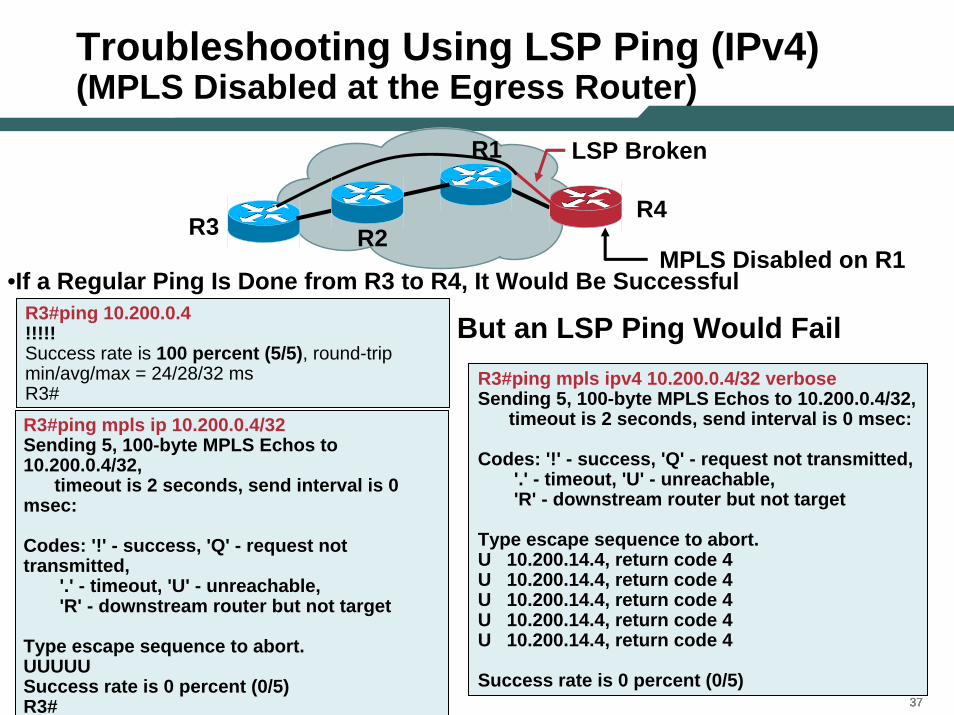
Troubleshooting Using LSP Ping (IPv4)(MPLS Disabled at the Egress Router)
MPLS Disabled on R1R3
R4
R1
R3#ping 10.200.0.4!!!!!Success rate is 100 percent (5/5), round-trip min/avg/max = 24/28/32 msR3#
LSP Broken
R3#ping mpls ipv4 10.200.0.4/32 verboseSending 5, 100-byte MPLS Echos to 10.200.0.4/32,
timeout is 2 seconds, send interval is 0 msec:
Codes: '!' - success, 'Q' - request not transmitted,'.' - timeout, 'U' - unreachable,'R' - downstream router but not target
Type escape sequence to abort.U 10.200.14.4, return code 4U 10.200.14.4, return code 4U 10.200.14.4, return code 4U 10.200.14.4, return code 4U 10.200.14.4, return code 4
Success rate is 0 percent (0/5)
•If a Regular Ping Is Done from R3 to R4, It Would Be Successful
R2
But an LSP Ping Would Fail
R3#ping mpls ip 10.200.0.4/32Sending 5, 100-byte MPLS Echos to 10.200.0.4/32,
timeout is 2 seconds, send interval is 0 msec:
Codes: '!' - success, 'Q' - request not transmitted,
'.' - timeout, 'U' - unreachable,'R' - downstream router but not target
Type escape sequence to abort.UUUUUSuccess rate is 0 percent (0/5)R3#
383838
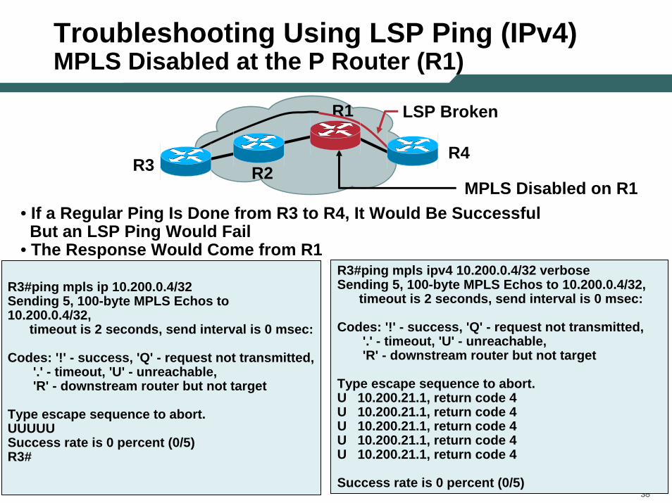
Troubleshooting Using LSP Ping (IPv4)MPLS Disabled at the P Router (R1)
R3MPLS Disabled on R1
R3#ping mpls ip 10.200.0.4/32Sending 5, 100-byte MPLS Echos to 10.200.0.4/32,
timeout is 2 seconds, send interval is 0 msec:
Codes: '!' - success, 'Q' - request not transmitted,'.' - timeout, 'U' - unreachable,'R' - downstream router but not target
Type escape sequence to abort.UUUUUSuccess rate is 0 percent (0/5)R3#
R4
R1 LSP Broken
R3#ping mpls ipv4 10.200.0.4/32 verbose Sending 5, 100-byte MPLS Echos to 10.200.0.4/32,
timeout is 2 seconds, send interval is 0 msec:
Codes: '!' - success, 'Q' - request not transmitted,'.' - timeout, 'U' - unreachable,'R' - downstream router but not target
Type escape sequence to abort.U 10.200.21.1, return code 4U 10.200.21.1, return code 4U 10.200.21.1, return code 4U 10.200.21.1, return code 4U 10.200.21.1, return code 4
Success rate is 0 percent (0/5)
R2
• If a Regular Ping Is Done from R3 to R4, It Would Be SuccessfulBut an LSP Ping Would Fail
• The Response Would Come from R1
393939
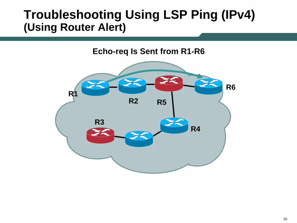
Troubleshooting Using LSP Ping (IPv4)(Using Router Alert)
Echo-req Is Sent from R1-R6
R1R6
R5
R3R4
R2
404040
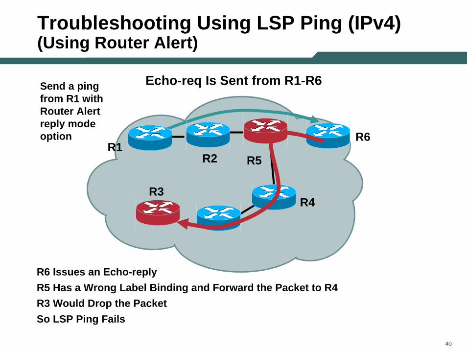
Troubleshooting Using LSP Ping (IPv4)(Using Router Alert)
Echo-req Is Sent from R1-R6
R1R6
R5
R3R4
R2
R6 Issues an Echo-replyR5 Has a Wrong Label Binding and Forward the Packet to R4R3 Would Drop the PacketSo LSP Ping Fails
Send a ping from R1 with Router Alert reply mode option
414141
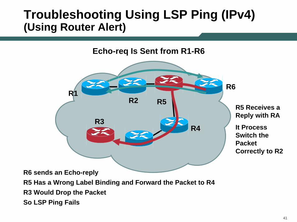
Troubleshooting Using LSP Ping (IPv4)(Using Router Alert)
Echo-req Is Sent from R1-R6
R1R6
R5
R3R4
R2R5 Receives a Reply with RA
It Process Switch the Packet Correctly to R2
R6 sends an Echo-replyR5 Has a Wrong Label Binding and Forward the Packet to R4R3 Would Drop the PacketSo LSP Ping Fails
424242
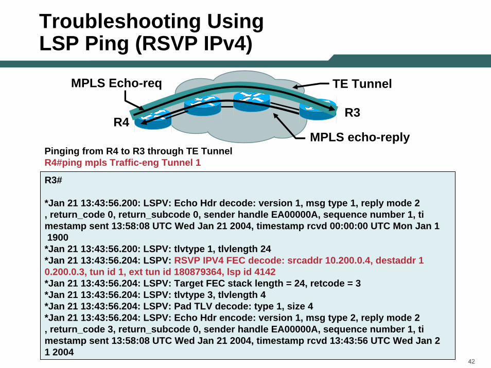
Troubleshooting UsingLSP Ping (RSVP IPv4)
Pinging from R4 to R3 through TE TunnelR4#ping mpls Traffic-eng Tunnel 1
MPLS echo-replyR4
R3
TE TunnelMPLS Echo-req
R3#
*Jan 21 13:43:56.200: LSPV: Echo Hdr decode: version 1, msg type 1, reply mode 2, return_code 0, return_subcode 0, sender handle EA00000A, sequence number 1, timestamp sent 13:58:08 UTC Wed Jan 21 2004, timestamp rcvd 00:00:00 UTC Mon Jan 11900
*Jan 21 13:43:56.200: LSPV: tlvtype 1, tlvlength 24*Jan 21 13:43:56.204: LSPV: RSVP IPV4 FEC decode: srcaddr 10.200.0.4, destaddr 10.200.0.3, tun id 1, ext tun id 180879364, lsp id 4142*Jan 21 13:43:56.204: LSPV: Target FEC stack length = 24, retcode = 3*Jan 21 13:43:56.204: LSPV: tlvtype 3, tlvlength 4*Jan 21 13:43:56.204: LSPV: Pad TLV decode: type 1, size 4*Jan 21 13:43:56.204: LSPV: Echo Hdr encode: version 1, msg type 2, reply mode 2, return_code 3, return_subcode 0, sender handle EA00000A, sequence number 1, timestamp sent 13:58:08 UTC Wed Jan 21 2004, timestamp rcvd 13:43:56 UTC Wed Jan 21 2004
434343
Troubleshooting Using LSP Ping (RSVP IPv4)
R1R3
Tunnel 1
Tunnel 2
R2
R4
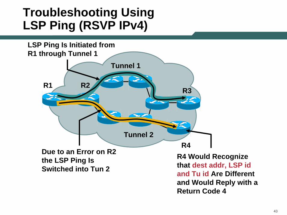
LSP Ping Is Initiated from R1 through Tunnel 1
Due to an Error on R2 the LSP Ping Is Switched into Tun 2
R4 Would Recognize that dest addr, LSP id and Tu id Are Different and Would Reply with a Return Code 4
444444
Agenda
• MPLS Overview• Existing Ping/Trace Capabilities • LSP Ping/Trace
–Theory of Operation
–MPLS Echo Packet
–Configuration and Troubleshooting Using LSP Ping/Trace
•LSP Ping
•LSP Trace
–AToM VCCV
• Summary
454545
Generating an LSP Trace
• For LSP Trace we generate an mpls-echo request and increment the TTL by 1 starting at 1
• Within the echo-req we add the downstream TLV • The TTL of the outermost label is set to 1 and then
incremented by 1 on every other request that is being send out
• The downstream routers, receiving the echo-req, would decrement the TTL by 1 and if it expires and the router is one of the downstream router it would reply with a return code of 6
• When the echo-req finally reaches the destination successfully router it would reply with a return code of 3
464646
LSP Trace: Path/Tree Trace (Cont.)
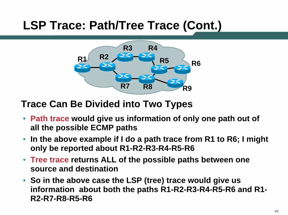
• Path trace would give us information of only one path out of all the possible ECMP paths
• In the above example if I do a path trace from R1 to R6; I mightonly be reported about R1-R2-R3-R4-R5-R6
• Tree trace returns ALL of the possible paths between one source and destination
• So in the above case the LSP (tree) trace would give us information about both the paths R1-R2-R3-R4-R5-R6 and R1-R2-R7-R8-R5-R6
R1R3
R2
R7
R6R5
R4
R8 R9
Trace Can Be Divided into Two Types
474747
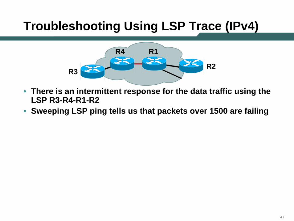
Troubleshooting Using LSP Trace (IPv4)
• There is an intermittent response for the data traffic using theLSP R3-R4-R1-R2
• Sweeping LSP ping tells us that packets over 1500 are failing
R3R2
R1R4
484848
Troubleshooting Using LSP Trace (IPv4)
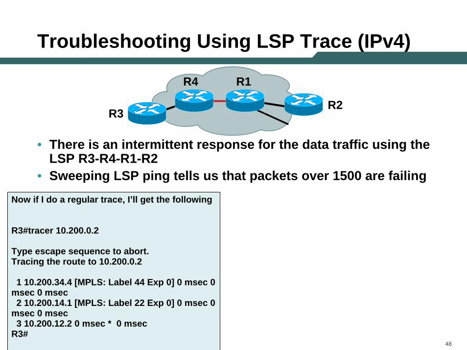
• There is an intermittent response for the data traffic using theLSP R3-R4-R1-R2
• Sweeping LSP ping tells us that packets over 1500 are failing
R3R2
R1R4
Now if I do a regular trace, I’ll get the following
R3#tracer 10.200.0.2
Type escape sequence to abort.Tracing the route to 10.200.0.2
1 10.200.34.4 [MPLS: Label 44 Exp 0] 0 msec 0 msec 0 msec2 10.200.14.1 [MPLS: Label 22 Exp 0] 0 msec 0
msec 0 msec3 10.200.12.2 0 msec * 0 msec
R3#
494949
Troubleshooting Using LSP Trace (IPv4)
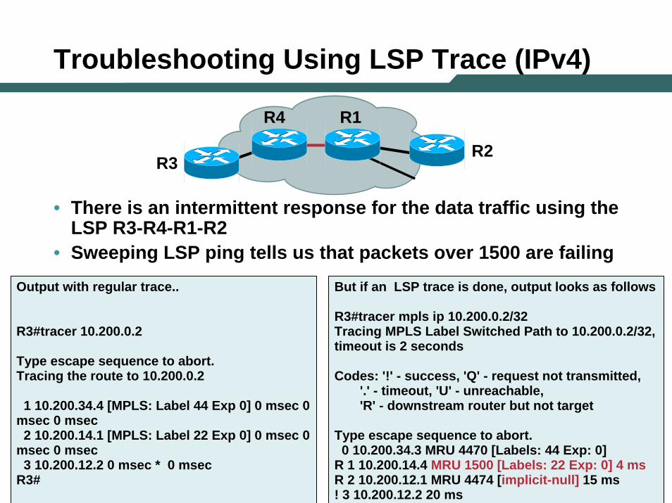
• There is an intermittent response for the data traffic using theLSP R3-R4-R1-R2
• Sweeping LSP ping tells us that packets over 1500 are failing
R3R2
R1R4
Output with regular trace..
R3#tracer 10.200.0.2
Type escape sequence to abort.Tracing the route to 10.200.0.2
1 10.200.34.4 [MPLS: Label 44 Exp 0] 0 msec 0 msec 0 msec2 10.200.14.1 [MPLS: Label 22 Exp 0] 0 msec 0
msec 0 msec3 10.200.12.2 0 msec * 0 msec
R3#
But if an LSP trace is done, output looks as follows
R3#tracer mpls ip 10.200.0.2/32Tracing MPLS Label Switched Path to 10.200.0.2/32, timeout is 2 seconds
Codes: '!' - success, 'Q' - request not transmitted,'.' - timeout, 'U' - unreachable,'R' - downstream router but not target
Type escape sequence to abort.0 10.200.34.3 MRU 4470 [Labels: 44 Exp: 0]
R 1 10.200.14.4 MRU 1500 [Labels: 22 Exp: 0] 4 msR 2 10.200.12.1 MRU 4474 [implicit-null] 15 ms! 3 10.200.12.2 20 ms
505050
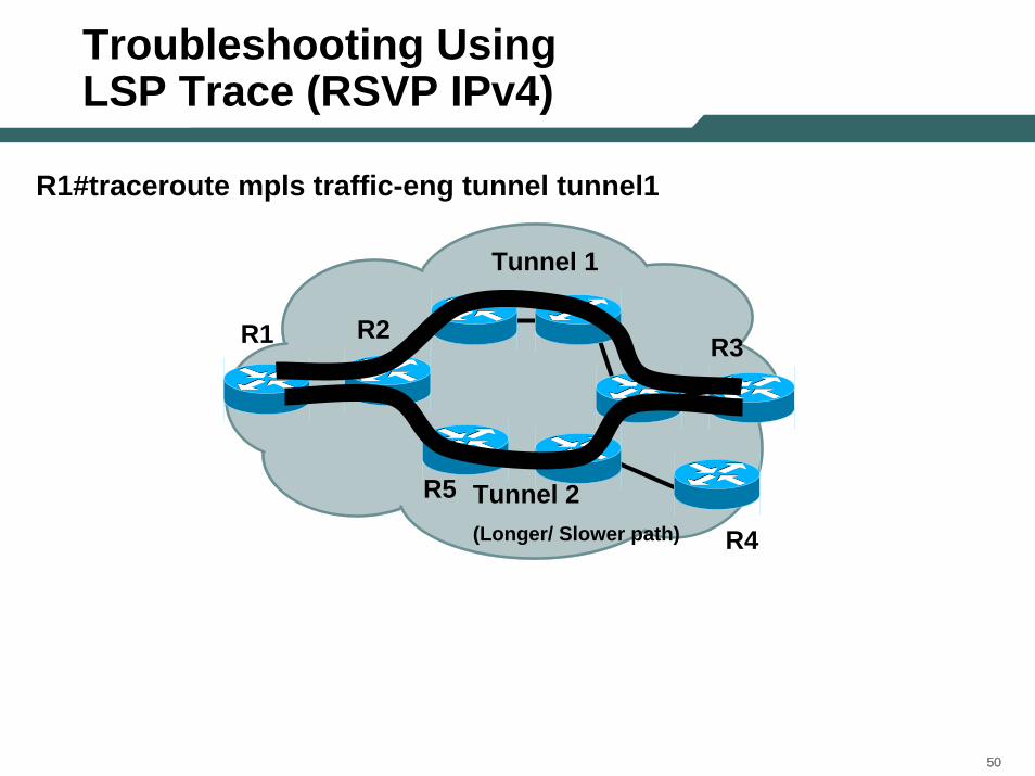
Troubleshooting Using LSP Trace (RSVP IPv4)
R1#traceroute mpls traffic-eng tunnel tunnel1
R1 R3
Tunnel 1
Tunnel 2 (Longer/ Slower path)
R2
R4
R5
515151
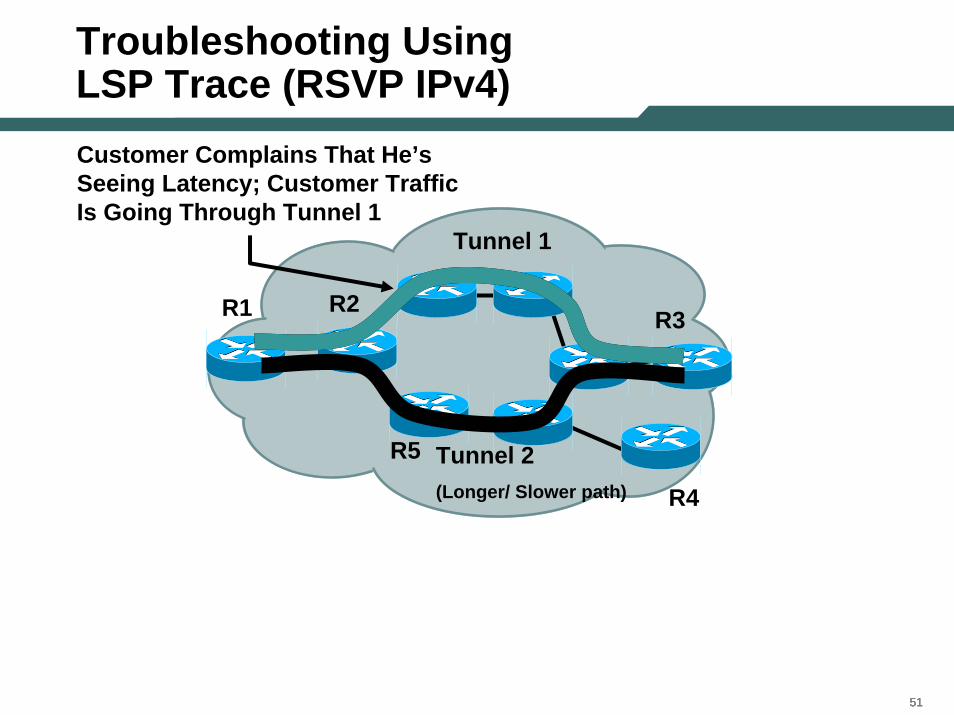
Troubleshooting UsingLSP Trace (RSVP IPv4)Customer Complains That He’s Seeing Latency; Customer Traffic Is Going Through Tunnel 1
R1 R3
Tunnel 1
R2
R4
R5 Tunnel 2 (Longer/ Slower path)
525252
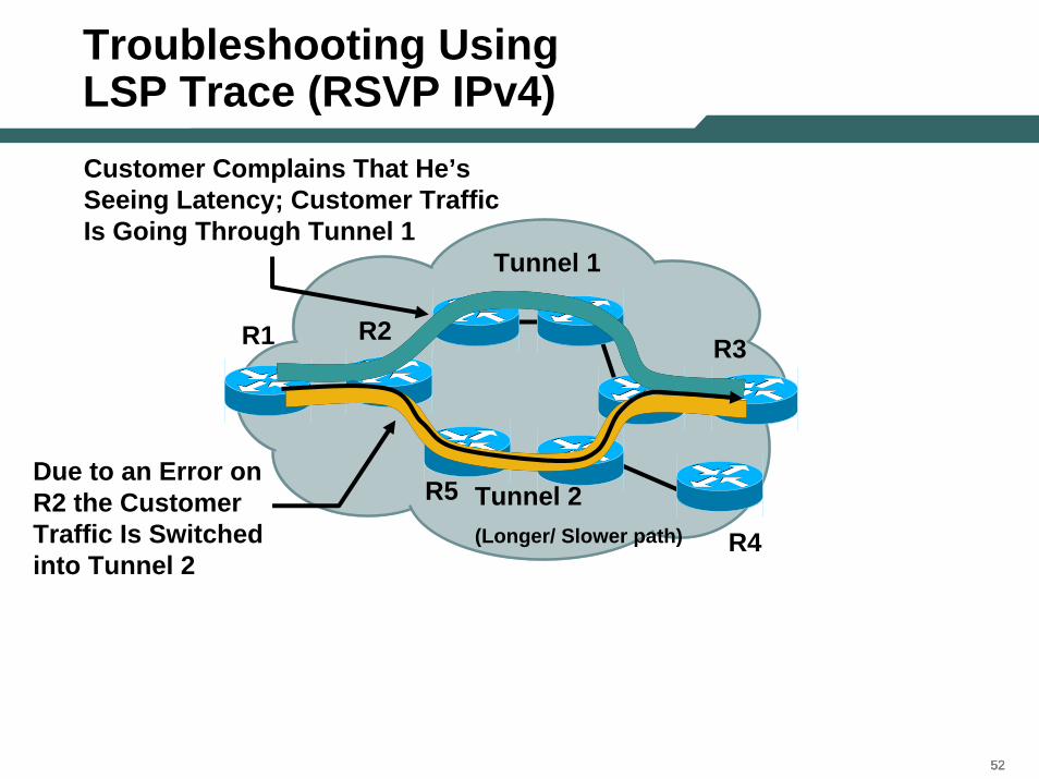
Troubleshooting UsingLSP Trace (RSVP IPv4)Customer Complains That He’s Seeing Latency; Customer Traffic Is Going Through Tunnel 1
Due to an Error on R2 the Customer Traffic Is Switched into Tunnel 2
R1 R3
Tunnel 1
R2
R4
R5 Tunnel 2 (Longer/ Slower path)
535353
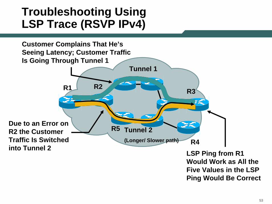
Troubleshooting UsingLSP Trace (RSVP IPv4)Customer Complains That He’s Seeing Latency; Customer Traffic Is Going Through Tunnel 1
Due to an Error on R2 the Customer Traffic Is Switched into Tunnel 2
LSP Ping from R1 Would Work as All the Five Values in the LSP Ping Would Be Correct
R1 R3
Tunnel 1
R2
R4
R5 Tunnel 2 (Longer/ Slower path)
545454
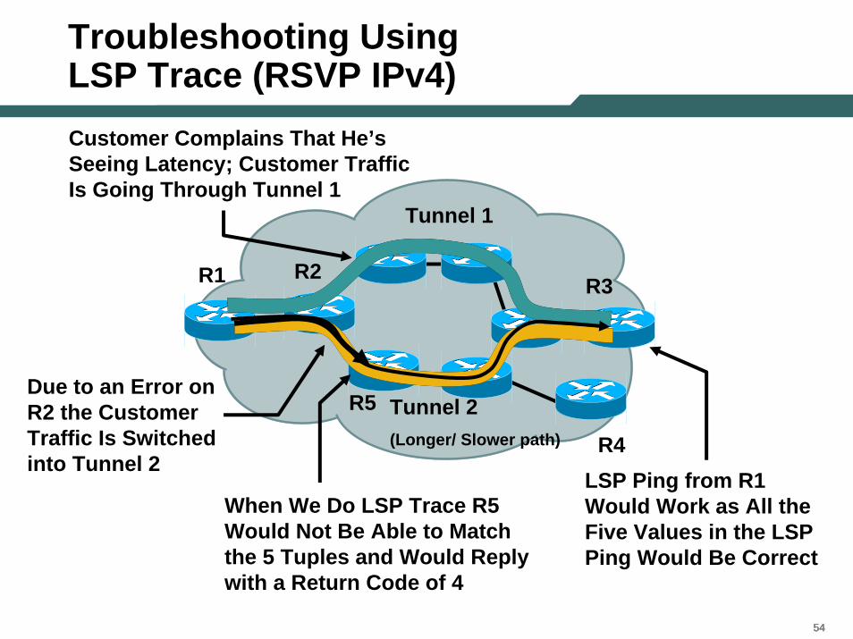
Troubleshooting UsingLSP Trace (RSVP IPv4)Customer Complains That He’s Seeing Latency; Customer Traffic Is Going Through Tunnel 1
Due to an Error on R2 the Customer Traffic Is Switched into Tunnel 2
LSP Ping from R1 Would Work as All the Five Values in the LSP Ping Would Be Correct
When We Do LSP Trace R5 Would Not Be Able to Match the 5 Tuples and Would Reply with a Return Code of 4
R1 R3
Tunnel 1
R2
R4
R5 Tunnel 2 (Longer/ Slower path)
55
Load Balancing (ECMP)
565656
Loadbalancing
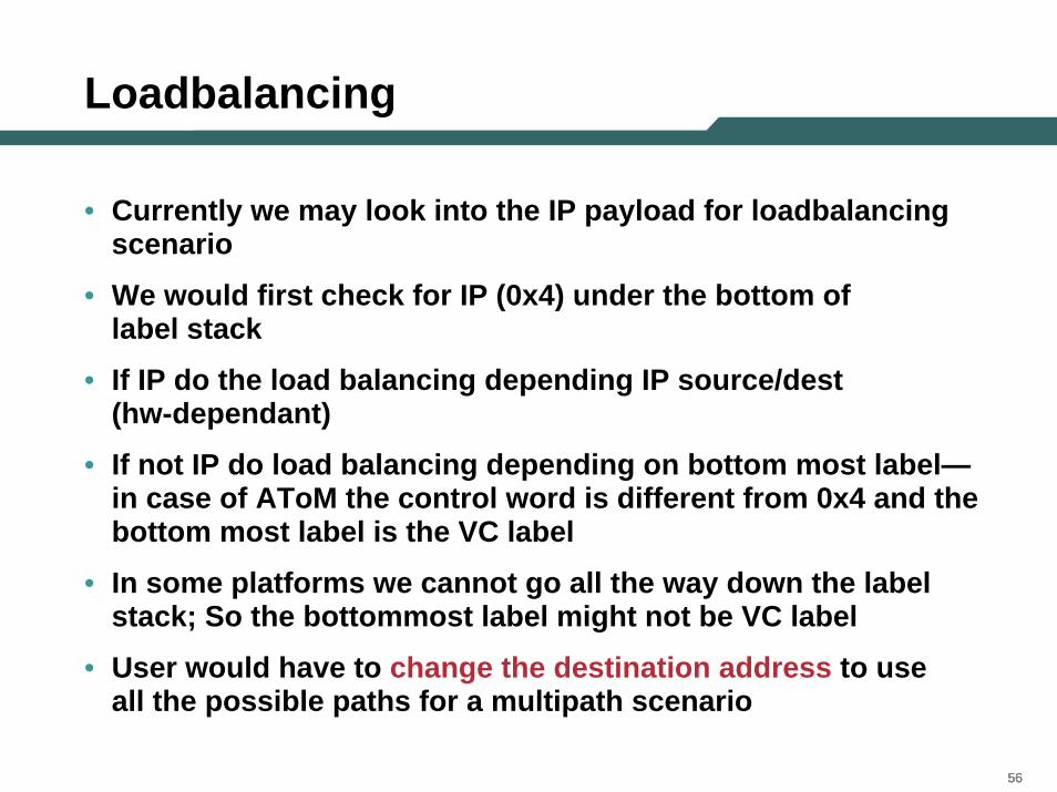
• Currently we may look into the IP payload for loadbalancing scenario
• We would first check for IP (0x4) under the bottom of label stack
• If IP do the load balancing depending IP source/dest (hw-dependant)
• If not IP do load balancing depending on bottom most label—in case of AToM the control word is different from 0x4 and the bottom most label is the VC label
• In some platforms we cannot go all the way down the label stack; So the bottommost label might not be VC label
• User would have to change the destination address to use all the possible paths for a multipath scenario
575757
Loadbalancing (Cont.)
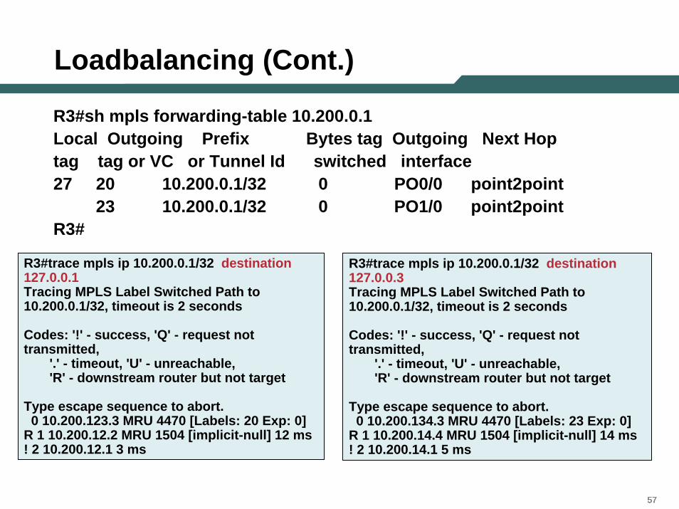
R3#sh mpls forwarding-table 10.200.0.1Local Outgoing Prefix Bytes tag Outgoing Next Hoptag tag or VC or Tunnel Id switched interface27 20 10.200.0.1/32 0 PO0/0 point2point
23 10.200.0.1/32 0 PO1/0 point2pointR3#
R3#trace mpls ip 10.200.0.1/32 destination 127.0.0.1Tracing MPLS Label Switched Path to 10.200.0.1/32, timeout is 2 seconds
Codes: '!' - success, 'Q' - request not transmitted,
'.' - timeout, 'U' - unreachable,'R' - downstream router but not target
Type escape sequence to abort.0 10.200.123.3 MRU 4470 [Labels: 20 Exp: 0]
R 1 10.200.12.2 MRU 1504 [implicit-null] 12 ms! 2 10.200.12.1 3 ms
R3#trace mpls ip 10.200.0.1/32 destination 127.0.0.3Tracing MPLS Label Switched Path to 10.200.0.1/32, timeout is 2 seconds
Codes: '!' - success, 'Q' - request not transmitted,
'.' - timeout, 'U' - unreachable,'R' - downstream router but not target
Type escape sequence to abort.0 10.200.134.3 MRU 4470 [Labels: 23 Exp: 0]
R 1 10.200.14.4 MRU 1504 [implicit-null] 14 ms! 2 10.200.14.1 5 ms
585858
Agenda
• MPLS Overview• Existing Ping/Trace Capabilities • LSP Ping/Trace
–Theory of Operation
–MPLS Echo Packet
–Configuration and Troubleshooting Using LSP Ping/Trace
•LSP Ping
•LSP Trace
–AToM VCCV
• Summary
595959
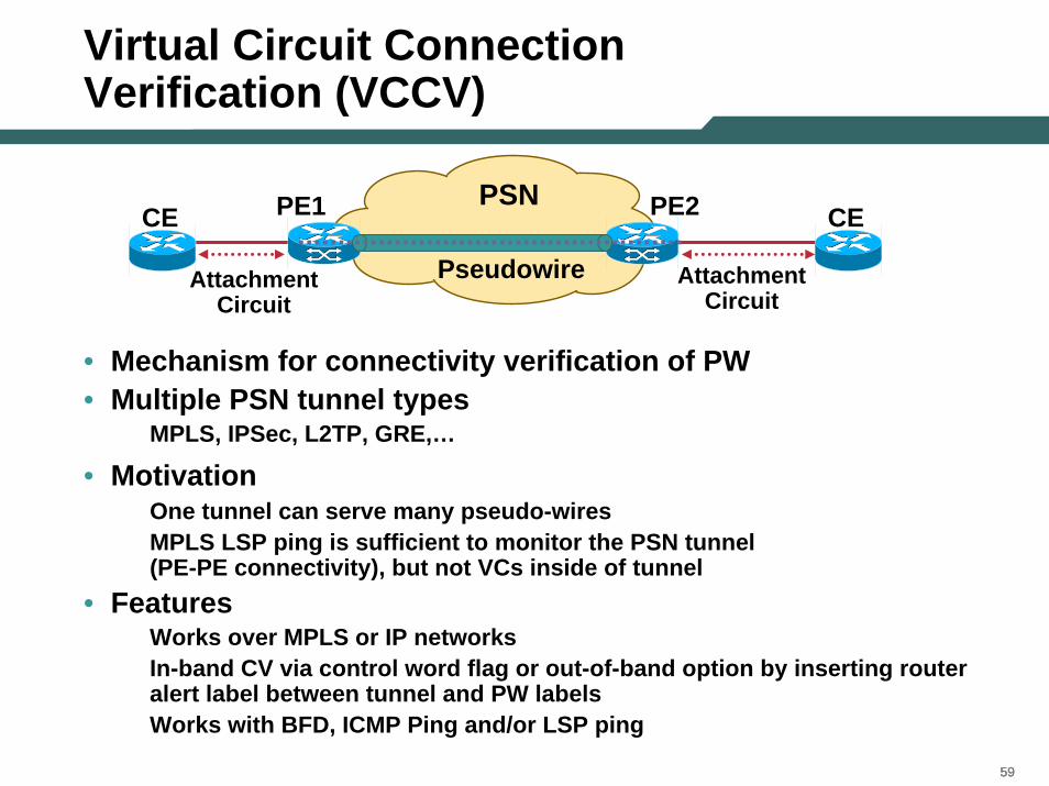
Virtual Circuit ConnectionVerification (VCCV)
PE2PE1
Attachment Circuit
CE CE
Attachment Circuit
PSN
Pseudowire
• Mechanism for connectivity verification of PW• Multiple PSN tunnel types
MPLS, IPSec, L2TP, GRE,…
• MotivationOne tunnel can serve many pseudo-wiresMPLS LSP ping is sufficient to monitor the PSN tunnel (PE-PE connectivity), but not VCs inside of tunnel
• FeaturesWorks over MPLS or IP networksIn-band CV via control word flag or out-of-band option by inserting router alert label between tunnel and PW labelsWorks with BFD, ICMP Ping and/or LSP ping
606060
VC Connection Verification (VCCV)
• Control packets inband of the AToM tunnels are intercepted by the egress PE
• A new martini interface parameter is defined
• VCCV capability is negotiated when the AToM tunnel is brought up
• VCCV marks the payload as control packet for switching purpose
616161
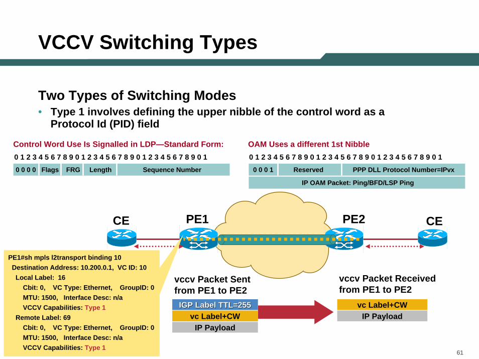
VCCV Switching Types
Two Types of Switching Modes• Type 1 involves defining the upper nibble of the control word as a
Protocol Id (PID) field
Control Word Use Is Signalled in LDP—Standard Form: OAM Uses a different 1st Nibble0 1 2 3 4 5 6 7 8 9 0 1 2 3 4 5 6 7 8 9 0 1 2 3 4 5 6 7 8 9 0 1 0 1 2 3 4 5 6 7 8 9 0 1 2 3 4 5 6 7 8 9 0 1 2 3 4 5 6 7 8 9 0 10 0 0 0 Flags FRG Length Sequence Number 0 0 0 1 Reserved PPP DLL Protocol Number=IPvx
IP OAM Packet: Ping/BFD/LSP Ping
PE2PE1CE CE
vccv Packet Sent from PE1 to PE2
vccv Packet Received from PE1 to PE2
vc Label+CWIP Payload
IGP Label TTL=255IGP Label TTL=255 vc Label+CWIP Payload
PE1#sh mpls l2transport binding 10Destination Address: 10.200.0.1, VC ID: 10Local Label: 16
Cbit: 0, VC Type: Ethernet, GroupID: 0MTU: 1500, Interface Desc: n/aVCCV Capabilities: Type 1
Remote Label: 69Cbit: 0, VC Type: Ethernet, GroupID: 0MTU: 1500, Interface Desc: n/aVCCV Capabilities: Type 1
626262
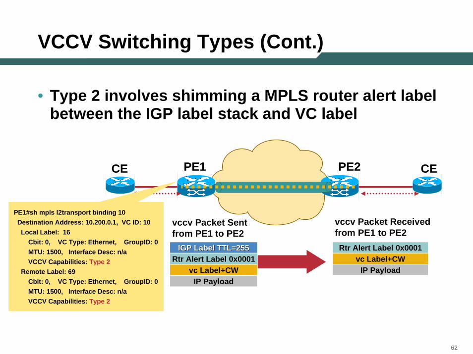
VCCV Switching Types (Cont.)
• Type 2 involves shimming a MPLS router alert label between the IGP label stack and VC label
PE2PE1CE CE
PE1#sh mpls l2transport binding 10Destination Address: 10.200.0.1, VC ID: 10Local Label: 16
Cbit: 0, VC Type: Ethernet, GroupID: 0MTU: 1500, Interface Desc: n/aVCCV Capabilities: Type 2
Remote Label: 69Cbit: 0, VC Type: Ethernet, GroupID: 0MTU: 1500, Interface Desc: n/aVCCV Capabilities: Type 2
vccv Packet Sent from PE1 to PE2
vccv Packet Received from PE1 to PE2
IP Payload
Rtr Alert Label 0x0001vc Label+CW
IGP Label TTL=255IGP Label TTL=255
IP Payload
Rtr Alert Label 0x0001vc Label+CW
636363
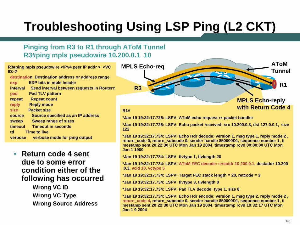
Troubleshooting Using LSP Ping (L2 CKT)
R3
• Return code 4 sent due to some error condition either of the following has occurred
Wrong VC ID Wrong VC TypeWrong Source Address
AToM Tunnel
MPLS Echo-req
R1#*Jan 19 19:32:17.726: LSPV: AToM echo request rx packet handler*Jan 19 19:32:17.726: LSPV: Echo packet received: src 10.200.0.3, dst 127.0.0.1, size 122*Jan 19 19:32:17.734: LSPV: Echo Hdr decode: version 1, msg type 1, reply mode 2 , return_code 0, return_subcode 0, sender handle 850000D1, sequence number 1, ti mestamp sent 20:22:30 UTC Mon Jan 19 2004, timestamp rcvd 00:00:00 UTC Mon Jan 1 1900*Jan 19 19:32:17.734: LSPV: tlvtype 1, tlvlength 20*Jan 19 19:32:17.734: LSPV: AToM FEC decode: srcaddr 10.200.0.1, destaddr 10.200 .0.3, vcid 10, vctype 5*Jan 19 19:32:17.734: LSPV: Target FEC stack length = 20, retcode = 3*Jan 19 19:32:17.734: LSPV: tlvtype 3, tlvlength 8*Jan 19 19:32:17.734: LSPV: Pad TLV decode: type 1, size 8*Jan 19 19:32:17.734: LSPV: Echo Hdr encode: version 1, msg type 2, reply mode 2 , return_code 4, return_subcode 0, sender handle 850000D1, sequence number 1, ti mestamp sent 20:22:30 UTC Mon Jan 19 2004, timestamp rcvd 19:32:17 UTC Mon Jan 1 9 2004
R1
MPLS Echo-reply with Return Code 4
R3#ping mpls pseudowire <IPv4 peer IP addr > <VC ID>?destination Destination address or address rangeexp EXP bits in mpls headerinterval Send interval between requests in Routercpad Pad TLV patternrepeat Repeat countreply Reply modesize Packet sizesource Source specified as an IP addresssweep Sweep range of sizestimeout Timeout in secondsttl Time to liveverbose verbose mode for ping output
Pinging from R3 to R1 through AToM TunnelR3#ping mpls pseudowire 10.200.0.1 10
646464
Agenda
• MPLS Overview• Existing Ping/Trace Capabilities • LSP Ping/Trace
–Theory of Operation
–MPLS Echo Packet
–Configuration and Troubleshooting Using LSP Ping/Trace
•LSP Ping
•LSP Trace
–AToM VCCV
• Summary
656565
Summary
• Traditional ping/trace not able to detect the problems in the MPLS networks.
• LSP ping/trace brings a new set of tools to troubleshoot MPLS forwarding plane problems
• VCCV adds new capability to help troubleshoot layer2 VPN issues

66
Backup Slides
676767
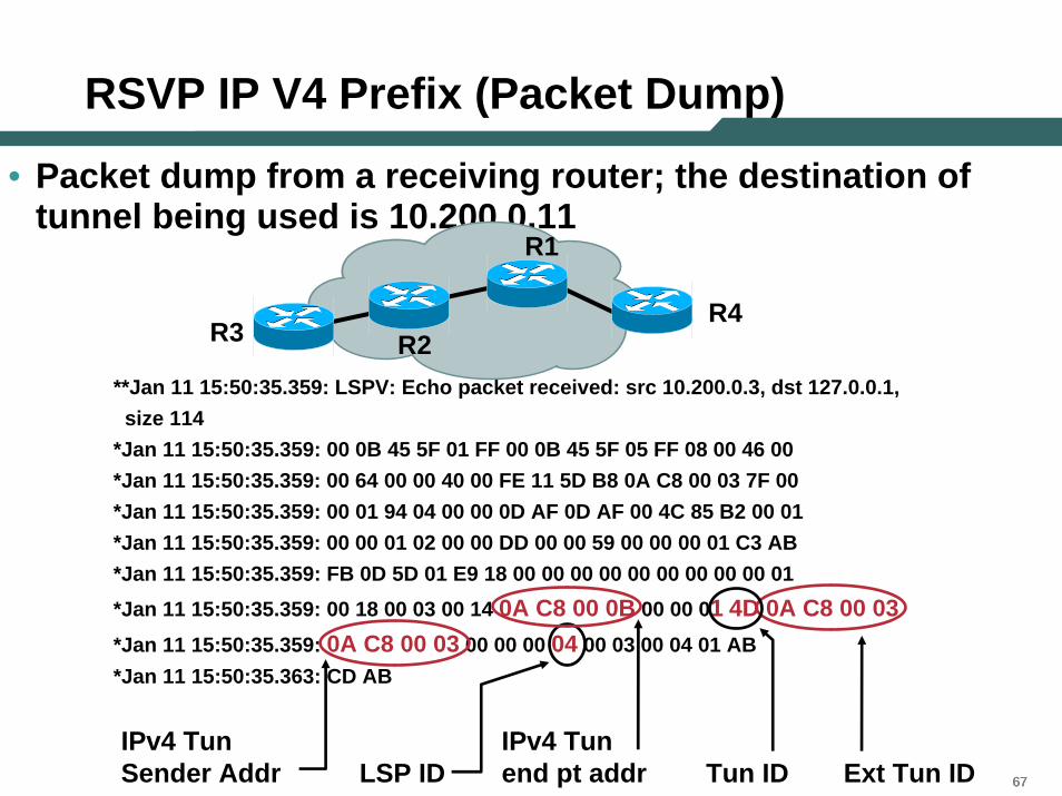
RSVP IP V4 Prefix (Packet Dump)
• Packet dump from a receiving router; the destination of tunnel being used is 10.200.0.11
**Jan 11 15:50:35.359: LSPV: Echo packet received: src 10.200.0.3, dst 127.0.0.1,size 114
*Jan 11 15:50:35.359: 00 0B 45 5F 01 FF 00 0B 45 5F 05 FF 08 00 46 00*Jan 11 15:50:35.359: 00 64 00 00 40 00 FE 11 5D B8 0A C8 00 03 7F 00*Jan 11 15:50:35.359: 00 01 94 04 00 00 0D AF 0D AF 00 4C 85 B2 00 01*Jan 11 15:50:35.359: 00 00 01 02 00 00 DD 00 00 59 00 00 00 01 C3 AB*Jan 11 15:50:35.359: FB 0D 5D 01 E9 18 00 00 00 00 00 00 00 00 00 01*Jan 11 15:50:35.359: 00 18 00 03 00 14 0A C8 00 0B 00 00 01 4D 0A C8 00 03*Jan 11 15:50:35.359: 0A C8 00 03 00 00 00 04 00 03 00 04 01 AB*Jan 11 15:50:35.363: CD AB
IPv4 Tun Sender Addr LSP ID Tun ID Ext Tun ID
IPv4 Tun end pt addr
R3R4
R1
R2
686868
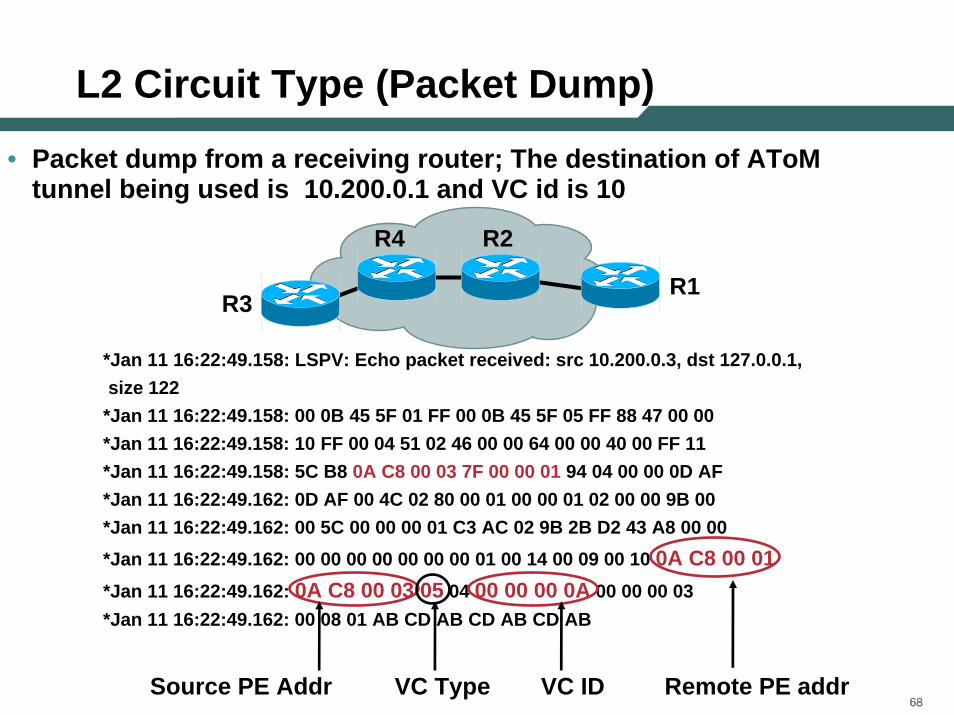
L2 Circuit Type (Packet Dump)
• Packet dump from a receiving router; The destination of AToM tunnel being used is 10.200.0.1 and VC id is 10
*Jan 11 16:22:49.158: LSPV: Echo packet received: src 10.200.0.3, dst 127.0.0.1,size 122
*Jan 11 16:22:49.158: 00 0B 45 5F 01 FF 00 0B 45 5F 05 FF 88 47 00 00*Jan 11 16:22:49.158: 10 FF 00 04 51 02 46 00 00 64 00 00 40 00 FF 11*Jan 11 16:22:49.158: 5C B8 0A C8 00 03 7F 00 00 01 94 04 00 00 0D AF*Jan 11 16:22:49.162: 0D AF 00 4C 02 80 00 01 00 00 01 02 00 00 9B 00*Jan 11 16:22:49.162: 00 5C 00 00 00 01 C3 AC 02 9B 2B D2 43 A8 00 00*Jan 11 16:22:49.162: 00 00 00 00 00 00 00 01 00 14 00 09 00 10 0A C8 00 01*Jan 11 16:22:49.162: 0A C8 00 03 05 04 00 00 00 0A 00 00 00 03*Jan 11 16:22:49.162: 00 08 01 AB CD AB CD AB CD AB
Source PE Addr VC Type VC ID Remote PE addr
R3R1
R2R4
696969
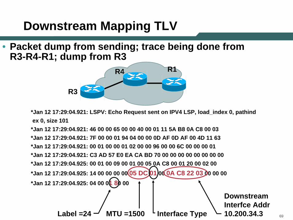
Downstream Mapping TLV • Packet dump from sending; trace being done from
R3-R4-R1; dump from R3
R3
R1R4
*Jan 12 17:29:04.921: LSPV: Echo Request sent on IPV4 LSP, load_index 0, pathindex 0, size 101
*Jan 12 17:29:04.921: 46 00 00 65 00 00 40 00 01 11 5A B8 0A C8 00 03*Jan 12 17:29:04.921: 7F 00 00 01 94 04 00 00 0D AF 0D AF 00 4D 11 63*Jan 12 17:29:04.921: 00 01 00 00 01 02 00 00 96 00 00 6C 00 00 00 01*Jan 12 17:29:04.921: C3 AD 57 E0 EA CA BD 70 00 00 00 00 00 00 00 00*Jan 12 17:29:04.925: 00 01 00 09 00 01 00 05 0A C8 00 01 20 00 02 00*Jan 12 17:29:04.925: 14 00 00 00 00 05 DC 01 00 0A C8 22 03 00 00 00*Jan 12 17:29:04.925: 04 00 01 80 00
MTU =1500 Interface Type
Downstream Interfce Addr 10.200.34.3Label =24

THANK YOU
707070