Embed Size (px)
Citation preview

MPLS Configuration
Table of Contents
Table of Contents
Chapter 1 MPLS Configuration............................................................................................................................................. 1
1.1 MPLS Overview..................................................................................................................................................... 1 1.2 Related Concepts of MPLS ................................................................................................................................... 1
1.2.1 Forwarding Equivalence Classes .............................................................................................................. 1 1.2.2 Label.......................................................................................................................................................... 2 1.2.3 Label Forwarding Information Database ................................................................................................... 4
1.3 Reading Before MPLS Configuration .................................................................................................................... 5 1.4 MPLS Configuration .............................................................................................................................................. 6
1.4.1 MPLS Configuration Task List ................................................................................................................... 6 1.4.2 Enabling MPLS.......................................................................................................................................... 6 1.4.3 Configuring Static LSP .............................................................................................................................. 7 1.4.4 Configures the label range. ....................................................................................................................... 8 1.4.5 Clears the MPLS counter. ......................................................................................................................... 9 1.4.6 Browsing MPLS Information...................................................................................................................... 9
1.5 LDP Configuration ............................................................................................................................................... 10 1.5.1 LDP Configuration Task List .................................................................................................................... 10 1.5.2 Configuring LSR Label ............................................................................................................................ 10 1.5.3 Enabling LDP .......................................................................................................................................... 11 1.5.4 Configuring Transmission Address.......................................................................................................... 11 1.5.5 Configuring the Address List of Label Distribution................................................................................... 12 1.5.6 Configuring the Parameter About Local Discovery Mechanism .............................................................. 12 1.5.7 Configuring the LDP Neighbor ................................................................................................................ 13 1.5.8 Configuring the Discovery Mechanism of a Designated Neighbor .......................................................... 13 1.5.9 Configuring the Holdtime of the Session ................................................................................................. 14 1.5.10 Force Explicit-Null Label........................................................................................................................ 14 1.5.11 Configuring LDP Log Record................................................................................................................. 15 1.5.12 Browsing LDP Information..................................................................................................................... 15
Chapter 2 MPLS L2VPN Configuration .............................................................................................................................. 16
2.1 Overview of MPLS L2VPN .................................................................................................................................. 16 2.2 Related Concepts of MPLS L2VPN..................................................................................................................... 16
2.2.1 VFI........................................................................................................................................................... 16 2.2.2 Pseudo-Wire............................................................................................................................................ 16 2.2.3 L2VPN Network Without Loopback......................................................................................................... 17
2.3 MPLS L2VPN Configuration................................................................................................................................ 17 2.3.1 MPLS L2VPN Configuration Task List..................................................................................................... 17 2.3.2 Enabling MPLS L2VPN ........................................................................................................................... 17 2.3.3 Creating VFI ............................................................................................................................................ 17 2.3.4 Binding VFI to VLAN Interface ................................................................................................................ 18 2.3.5 Configuring Incoming VFI Interface......................................................................................................... 19 2.3.6 Configuring a Static VC Label ................................................................................................................. 19 2.3.7 Browsing L2VPN Information .................................................................................................................. 20
- I -
Table of Contents
- II -
2.4 MPLS L2VPN Configuration Example ................................................................................................................. 20 2.4.1 Point-to-Point L2VPN Configuration Example......................................................................................... 20
Chapter 3 MPLS L3VPN Configuration .............................................................................................................................. 24
3.1 Overview of MPLS L3VPN .................................................................................................................................. 24 3.2 MPLS L3VPN Configuration................................................................................................................................ 25
3.2.1 MPLS L3VPN Configuration Task List..................................................................................................... 25 3.2.2 Configuring MPLS ................................................................................................................................... 25 3.2.3 Configuring LDP...................................................................................................................................... 26 3.2.4 Configuring VRF...................................................................................................................................... 26 3.2.5 Configuring a VPN Route........................................................................................................................ 27 3.2.6 Configuring a Route Between PE and P ................................................................................................. 27 3.2.7 Configuring a BGP Route Between PEs ................................................................................................. 28
3.3 MPLS L3VPN Configuration Example ................................................................................................................. 29 3.3.1 Configuring S1 (CE) ................................................................................................................................ 29 3.3.2 Configuring S2 (PE) ................................................................................................................................ 30 3.3.3 Configuring S3 (P)................................................................................................................................... 32
MPLS Configuration
Chapter 1 MPLS Configuration
1.1 MPLS Overview
Multiprotocol Label Switching (MPLS) is used to encapsulate packets from the network layer with short and long-specific labels. MPLS separates route choosing and data forwarding, and designates the network path of a packet with a label. The MPLS network consists of the Label Switching Router (LSR) and the Label Edge Router (LER). Seen as the comibination of the ATM switch and the traditional router, the LSR consists of the control unit and the switching unit. The LER is to analyze the headers of IP packets to decide the corresponding transmission grade and the label switching path.
In the MPLS network, the device supporting label switching is called as LSR. The connection of these LSRs is composed of the Label Switching Path (LSP). The label information can be switched among LSRs through the Label Distribute Protocol (LDP), the expanded routing protocol and other methods. The ingress LSR on LSP adds a label to a packet according to the network-layer information (for example, the IP header), while the egress LSR will remove the label. Other LSRs just forward the packet according to the label.
The MPLS network adds labels to packets, which makes data forwarding more connection-oriented though the control function of the MPLS network is based on the current IP technology. The LSR role can be taken by many types of MPLS-supported devices, such as the router or the layer-3 switch.
MPLS is originally a protocol that is used to improve the forwarding speed of the router; however, thanks to its fixed advantages, MPLS is also applied on traffic engineering, VPN, etc. Therefore, it gradually becomes a vital standard of a large-scale IP network.
1.2 Related Concepts of MPLS
1.2.1 Forwarding Equivalence Classes
Forwarding Equivalence Classes (FEC) is an important concept in MPLS. FEC presents a group of packets with the same forwarding method, such as having the same address prefix and the same forwarding path.
When a packet is transmitted in a network under the effect of the connectionless network protocols, each router that the packet passes through needs to conduct path choice independently to the packet. The procedure of selecting the next hop can be considered as performing the following two steps: (a) Classifying packets into different FECs; (b) Deciding the next hop for each FEC. If only the function of forwarding packets is considered, the packets that are classified to pass through an FEC are same because they are transmitted in the same path.
In traditional IP packet forwarding, the reasom why a router thinks two packets are in the same FEC is that the destination addresses of the two packets can match up with
- 1 -
MPLS Configuration
a certain item in the routing table at full length. On each hop of the packet, the router needs to recheck this packet to decide the FEC that the packet belongs to.
However, in MPLS, the operation to assign a packet to a FCC is conducted only once when the packet enters the network. On the ingress router of the network, the FEC that a packet belongs to is presented as a value with fixed length, that is, a label, and the label will be placed into the packet. At the next hop, the router does not need to check the network-layer header of the packet any more, but directly decides the new next hop of the packet according to the label, and then replaces the previous label with a new label and forwards it out.
1.2.2 Label
1. Definition
The label is a short, long-specific and meaningful identifier symbol only between two neighboring LSRs, which is used to represent as a FEC. In general, The FEC where the packet lies is up to the destination address of the network layer.
The label is meaningful only between two neighboring LSRs. For example, both router Ru and router Rd support label switching, and they agree on this: if a packet belongs to FEC F, router Ru adds label L to the packet when router Ru sends the packet to router Rd, that is, a binding relation is established between Label L and FEC F. The binding relation is valid to those packets that are transmitted from router Ru to router Rd. It needs to be noted that label L is just a random value used between router Ru and router Rd.
2. Structure of the Label
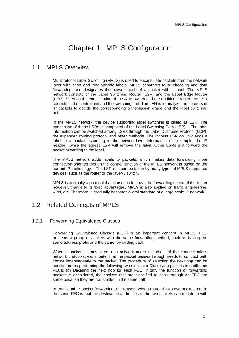
MPLS is to add multiple labels to a packet to form a label stack in the packet. RFC3032 defines the label stack’s structure which is applied in the PPP link or the Ethernet link. The structure of each item in the label stack is shown in figure 1.1.
Figure 1.1 Structure of the item in the label stack
Label: Real value of the stack label, whose length is 20 bits.
Exp: Reserved, generally appearing as COS, whose length is 3 bits
S: If the item is the last one in the label stack, S is set to 1, meaning the stack’s bottom. S of other items is 0, whose length is 1 bit.
TTL: It has the same meaning as the TTL of the IP header, whose length is 8 bits.
3. Label's Operation
(1) NHLFE
- 2 -
MPLS Configuration
The next-hop label forwarding entry is used to forward packets with label. It contains the following information: (a) the next hop of the packet; (b) operating the label stack of the packet; (c) other information.
(2) Label mapping
Label mapping means mapping a packet (with or without label) to one NHLFE item or a group of NHLFE items to decide the operation mode to the packet. Label mapping includes the label mapping at the egress router and the mapping at LSP.
The label mapping at the ingress router is also called as FEC-to-NHLFE map. After the LSR confirms the FEC of the packet, each FEC is mapped to a group of NHLFEs. handling the unlabelled packets at the ingress.
A mapping in LSP is also called an Incoming Label Map (ILM), which is used to map each incoming labeled packet to one NHLFE or a group of NHLFEs.
(3) Label distribution mode
Label distribution is a process to establish LSP for a certain FEC.
Mpls supports two label distribution modes: Downstream Unsolicited (DU) and Downstream On Demand (DoD).
In DU mode, LSR will actively distribute the labels and the FEC binding information without receiving the request.
In DoD mode, LSR will distribute labels only after the request information is obtained.
Note: BDCOM hi-end switches of 4.0.1A version and its former versions support the automatic label distribution mode.
(4) Label distribution control mode
MPLS has two label distribution control modes: Independent and Ordered.
In independent mode, if a LSR receives the label requests from other LSRs, the LSR can give prompt response to other LSRs without downstream-distributed label binding. The independent control mode allows LSR to distribute the label binding information to other LSRs at any time.
In ordered control mode, LSR can learn the label binding information only from the next stop, or LSR itself is the egress router of LSP. Hence LSR can distribute the label binding information to other LSRs.
Note: BDCOM hi-end switches of the 4.0.1A version and its former versions support the orderly label distribution mode.
(5) Label retention mode
Mpls has two label retention modes: conservation and liberal.
In conservation mode, LSR only saves the label binding information that it requires, not all received information.
- 3 -
MPLS Configuration
In liberal mode, LSR saves all received label binding information.
Note: BDCOM hi-end switches of 4.0.1A version and its former versions support the free label maintenance mode.
4. LDP
Label Distribution Protocol (LDP) applies the hop-to-hop or dynamic label distribution arithmetic to establish the try-the-best LSP among LSRs through distributing labels to the routes learned by IGP.
LDP mainly runs on reliable TCP connections (unless UDP is used). LDP mainly executes the following four operations:
Discovery: It is to release and maintain the LSRs in the network.
Session: It is to establish and keep the sessions between two peer LDPs.
Advertisement: It is to distribute and spread the labels.
Notification: It is to notify the error information.
1.2.3 Label Forwarding Information Database
BDCOM Ethernet switch series are to maintain the FTN and LIM items that are used by MPLS packet forwarding through the label forwarding information database. The label forwarding information database consists of three parts: software forwarding information database, adjacent information database and hardware forwarding information database.
1.1.1.1 MLIB
MLIB is the simplified form of MPLS label information base. MLIB saves all forwarding information, including forwarding information that is generated by dynamic LDP and forwarding information that is configured by users manually. All the forwarding information varies with the states of LDP and the change of user's configuration.
The MPLS forwarding module realizes the CPU forwarding of the MPLS packets and the IP packets through MLIB query.
In the system of BDCOM S8500 switches, the MSU and each line card have corresponding MLIBs. All forwarding information is first generated in MLIB of the MSU and then synchronized to all MPLS line cards by MSU. MSU is always consistent with the MLIB of the MPLS.
1.1.1.2 Adjacent Information
The adjacent information about MPLS forwarding item includes:
- 4 -
MPLS Configuration
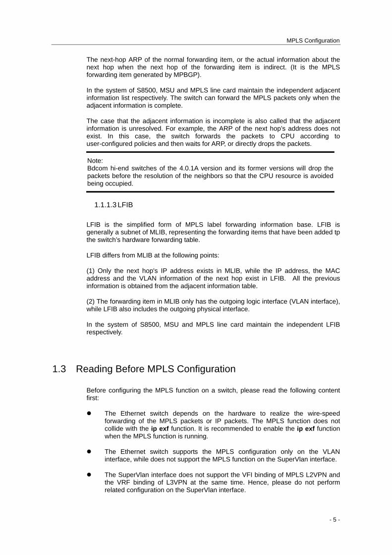
The next-hop ARP of the normal forwarding item, or the actual information about the next hop when the next hop of the forwarding item is indirect. (It is the MPLS forwarding item generated by MPBGP).
In the system of S8500, MSU and MPLS line card maintain the independent adjacent information list respectively. The switch can forward the MPLS packets only when the adjacent information is complete.
The case that the adjacent information is incomplete is also called that the adjacent information is unresolved. For example, the ARP of the next hop’s address does not exist. In this case, the switch forwards the packets to CPU according to user-configured policies and then waits for ARP, or directly drops the packets.
Note: Bdcom hi-end switches of the 4.0.1A version and its former versions will drop the packets before the resolution of the neighbors so that the CPU resource is avoided being occupied.
1.1.1.3 LFIB
LFIB is the simplified form of MPLS label forwarding information base. LFIB is generally a subnet of MLIB, representing the forwarding items that have been added tp the switch’s hardware forwarding table.
LFIB differs from MLIB at the following points:
(1) Only the next hop's IP address exists in MLIB, while the IP address, the MAC address and the VLAN information of the next hop exist in LFIB. All the previous information is obtained from the adjacent information table.
(2) The forwarding item in MLIB only has the outgoing logic interface (VLAN interface), while LFIB also includes the outgoing physical interface.
In the system of S8500, MSU and MPLS line card maintain the independent LFIB respectively.
1.3 Reading Before MPLS Configuration
Before configuring the MPLS function on a switch, please read the following content first:
The Ethernet switch depends on the hardware to realize the wire-speed forwarding of the MPLS packets or IP packets. The MPLS function does not collide with the ip exf function. It is recommended to enable the ip exf function when the MPLS function is running.
The Ethernet switch supports the MPLS configuration only on the VLAN interface, while does not support the MPLS function on the SuperVlan interface.
The SuperVlan interface does not support the VFI binding of MPLS L2VPN and the VRF binding of L3VPN at the same time. Hence, please do not perform related configuration on the SuperVlan interface.
- 5 -
MPLS Configuration
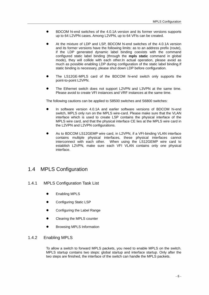
BDCOM hi-end switches of the 4.0.1A version and its former versions supports up to 64 L2VPN cases. Among L2VPN, up to 64 VFIs can be created.
At the mixture of LDP and LSP, BDCOM hi-end switches of the 4.0.1A version and its former versions have the following limits: as to an address prefix (route), if the LDP generated dynamic label binding coexists with the command configured static label binding (through the mpls static command in global mode), they will collide with each other.In actual operation, please avoid as much as possible enabling LDP during configuration of the static label binding.If static binding is necessary, please shut down LDP before configuration.
The LS12GE-MPLS card of the BDCOM hi-end switch only supports the point-to-point L2VPN.
The Ethernet switch does not support L2VPN and L3VPN at the same time. Please avoid to create VFI instances and VRF instances at the same time.
The following cautions can be applied to S8500 switches and S6800 switches:
In software version 4.0.1A and earlier software versions of BDCOM hi-end switch, MPLS only run on the MPLS wire-card. Please make sure that the VLAN interface which is used to create LSP contains the physical interface of the MPLS wire card, and that the physical interface CE lies at the MPLS wire card in the L2VPN and L2VPN configurations.
As to BDCOM LS12GEMP wire card, in L2VPN, if a VFI-binding VLAN interface contains multiple physical interfaces, these physical interfaces cannot interconnect with each other. When using the LS12GEMP wire card to establish L2VPN, make sure each VFI VLAN contains only one physical interface.
1.4 MPLS Configuration
1.4.1 MPLS Configuration Task List
Enabling MPLS
Configuring Static LSP
Configuring the Label Range
Clearing the MPLS counter
Browsing MPLS Information
1.4.2 Enabling MPLS
To allow a switch to forward MPLS packets, you need to enable MPLS on the switch. MPLS startup contains two steps: global startup and interface startup. Only after the two steps are finished, the interface of the switch can handle the MPLS packets.
- 6 -
MPLS Configuration
Run the following commands to enable MPLS in global mode:
Command Purpose
mpls ip Enables MPLS in global mode.
no mpls ip Disables MPLS in global mode.
Run the following commands to enable MPLS in interface configuration mode:
Command Purpose
mpls ip Enables MPLS on the VLAN interface.
no mpls ip Disables MPLS on the VLAN interface.
Remark: 1. MPLS can be enabled only on the VLAN interface. 2. The MPLS in interface configuration mode validates only after the MPLS is enabled in global mode.
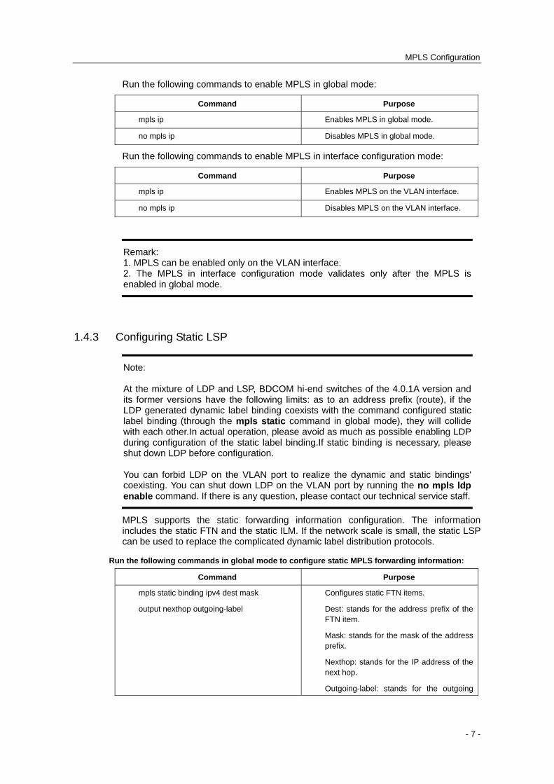
1.4.3 Configuring Static LSP
Note: At the mixture of LDP and LSP, BDCOM hi-end switches of the 4.0.1A version and its former versions have the following limits: as to an address prefix (route), if the LDP generated dynamic label binding coexists with the command configured static label binding (through the mpls static command in global mode), they will collide with each other.In actual operation, please avoid as much as possible enabling LDP during configuration of the static label binding.If static binding is necessary, please shut down LDP before configuration. You can forbid LDP on the VLAN port to realize the dynamic and static bindings' coexisting. You can shut down LDP on the VLAN port by running the no mpls ldp enable command. If there is any question, please contact our technical service staff.
MPLS supports the static forwarding information configuration. The information includes the static FTN and the static ILM. If the network scale is small, the static LSP can be used to replace the complicated dynamic label distribution protocols.
Run the following commands in global mode to configure static MPLS forwarding information:
Command Purpose
mpls static binding ipv4 dest mask
output nexthop outgoing-label
Configures static FTN items.
Dest: stands for the address prefix of the FTN item.
Mask: stands for the mask of the address prefix.
Nexthop: stands for the IP address of the next hop.
Outgoing-label: stands for the outgoing
- 7 -

MPLS Configuration
label, whose range is from 16 to 1048575.
mpls static crossconnect incoming-label
outgoing-intf nexthop outgoing-label
Configures static ILM items.
incoming-label: stands for the incoming label whose range is the static label range.
outgoing-intf: stands for the outgoing interface of the next hop.
Nexthop: stands for the IP address of the next hop.
Outgoing-label: stands for the outgoing label, whose range is from 16 to 1048575.
The negative forms of the previous commands can be used to cancel the corresponding static LSP configuration.
The static FTN items are generally configured on the edge router of LSP. The next hop’s IP address of the item can be a direct address or an indirect address. The indirect next hop’s FTN is normally used in MPLS L3VPN. In this case, the switch searches for an effective next-hop FTN for the indirect address automatically, and then binds the detected FTN to the indirect FTN to form a multi-layer label stack.
It is noted that, after the static FTN item is configured, you need to add a static route for a static FTN item or make sure that the FEC route corresponding to FTN is already learned by the dynamic routing protocol. As to a destination subnet, if you only configure the FTN item but the corresponding route does not exist, the LER switch cannot encapsulate packets into a label to forward them to the expected LSP.
1.4.4 Configures the label range.
MPLS allows to configure the dynamic or static label range.
Run the following commands in global mode to configure the label range:
Command Purpose
mpls label range min max
[ static min max ]
Configures the label range.
min: Means the minimum value of the label range, which is 1024 by default.
max: Means the maximum value of the label range, which is 1048575 by default.
static: Configures the range of static labels.
By default, the static label range is between 16 and 1023, while the dynamic label range is between 1024 and 1048575.
At present, our label range is automatically adjusted to the multiples of 32 for speeding up the research speed. In fact, labels of a 64K volume are supported. Labels 0-15 are values reserved by IETF, so you cannot use them during configuration.
If the label range is configured and the labels are not distributed to other modules, when the distribution range of the labels is changed, the new label range validates immediately; otherwise, the new label range will validate at the next startup.
- 8 -
MPLS Configuration
If the value range 16-1023 is the static label range and this static label range need be modified, the modified static label range cannot exceed the range 16-1023.
1.4.5 Clears the MPLS counter.
MPLS will automatically count the forwarded packets. In privileged mode, you can run the following command to clear the MPLS counter.
Command Purpose
clear mpls counters Clears the MPLS counter.
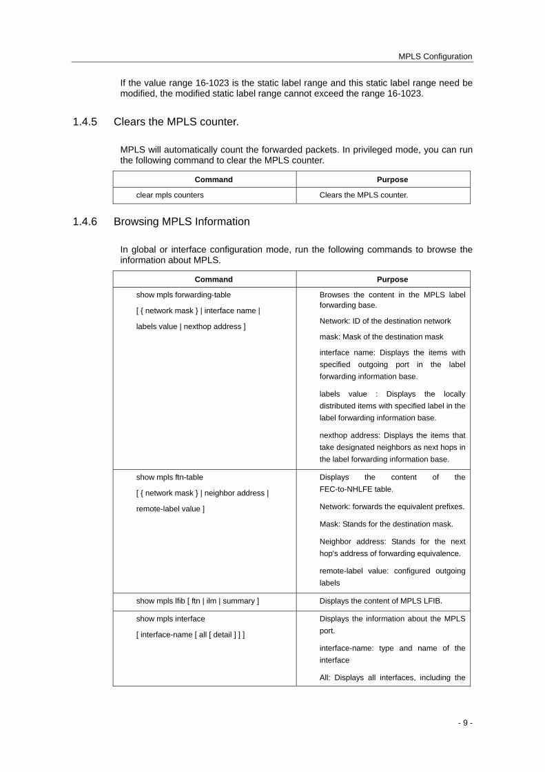
1.4.6 Browsing MPLS Information
In global or interface configuration mode, run the following commands to browse the information about MPLS.
Command Purpose
show mpls forwarding-table
[ { network mask } | interface name |
labels value | nexthop address ]
Browses the content in the MPLS label forwarding base.
Network: ID of the destination network
mask: Mask of the destination mask
interface name: Displays the items with
specified outgoing port in the label
forwarding information base.
labels value : Displays the locally
distributed items with specified label in the
label forwarding information base.
nexthop address: Displays the items that
take designated neighbors as next hops in
the label forwarding information base.
show mpls ftn-table
[ { network mask } | neighbor address |
remote-label value ]
Displays the content of the
FEC-to-NHLFE table.
Network: forwards the equivalent prefixes.
Mask: Stands for the destination mask.
Neighbor address: Stands for the next
hop's address of forwarding equivalence.
remote-label value: configured outgoing
labels
show mpls lfib [ ftn | ilm | summary ] Displays the content of MPLS LFIB.
show mpls interface
[ interface-name [ all [ detail ] ] ]
Displays the information about the MPLS
port.
interface-name: type and name of the
interface
All: Displays all interfaces, including the
- 9 -
MPLS Configuration
unconfigured MPLS IP interface.
detail: Displays MTU of the port and
export and import the statisitics value of
the MPLS packets.
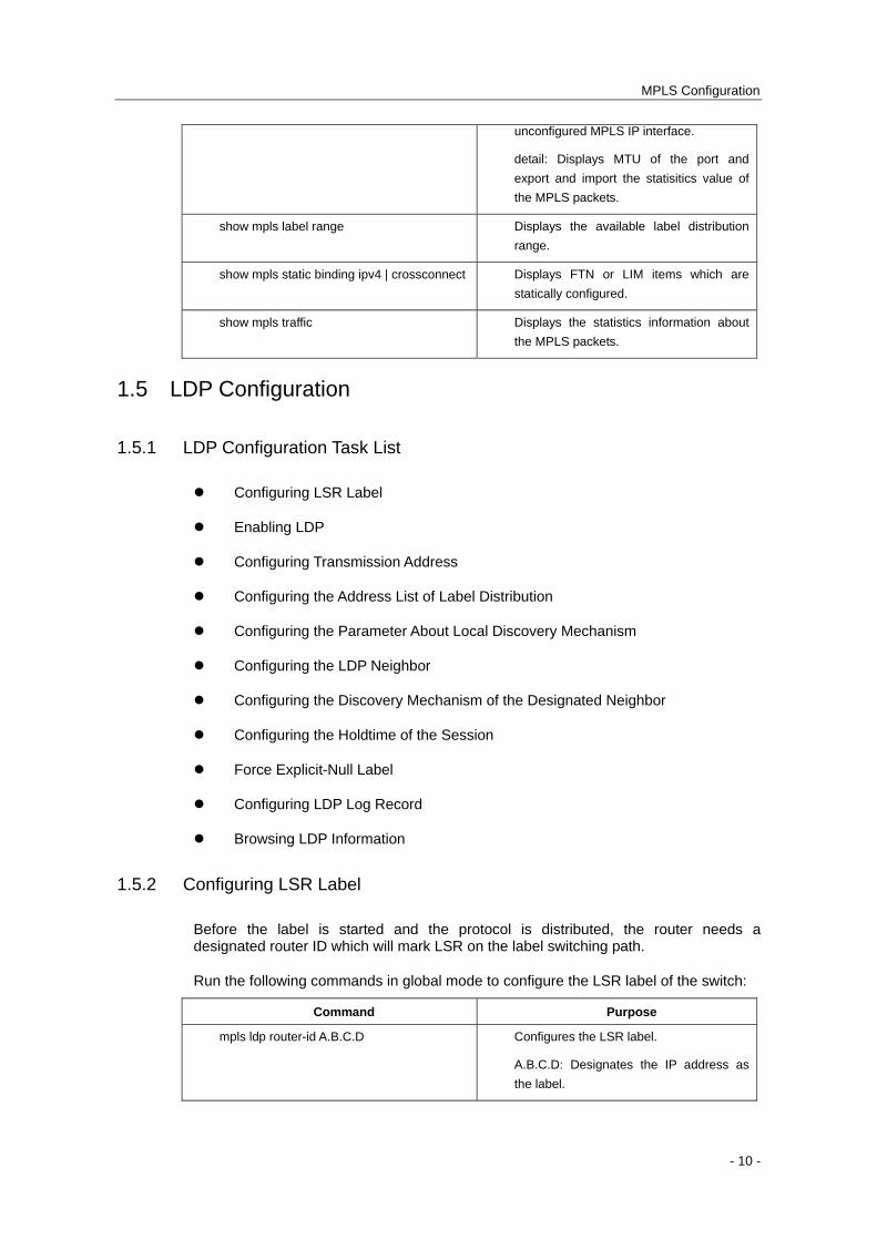
show mpls label range Displays the available label distribution
range.
show mpls static binding ipv4 | crossconnect Displays FTN or LIM items which are
statically configured.
show mpls traffic Displays the statistics information about
the MPLS packets.
1.5 LDP Configuration
1.5.1 LDP Configuration Task List
Configuring LSR Label
Enabling LDP
Configuring Transmission Address
Configuring the Address List of Label Distribution
Configuring the Parameter About Local Discovery Mechanism
Configuring the LDP Neighbor
Configuring the Discovery Mechanism of the Designated Neighbor
Configuring the Holdtime of the Session
Force Explicit-Null Label
Configuring LDP Log Record
Browsing LDP Information
1.5.2 Configuring LSR Label
Before the label is started and the protocol is distributed, the router needs a designated router ID which will mark LSR on the label switching path.
Run the following commands in global mode to configure the LSR label of the switch:
Command Purpose
mpls ldp router-id A.B.C.D Configures the LSR label.
A.B.C.D: Designates the IP address as
the label.
- 10 -
MPLS Configuration
Only the router ID is configured can LDP be enabled on an interface.
If the mpls ldp router-id command is configured, new router ID takes effect immediately and the LDP neighborhood is re-established.
It is recommended to configure the router ID as the address of the loopback interface for the TCP connection triggered by LDP Targeted Hello takes the router ID of the LDP neighbor as the addresses of two terminals of the socket, without which the neighbor will fail to be established.
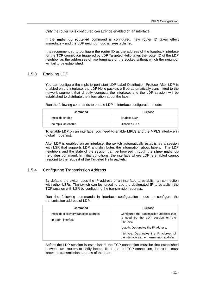
1.5.3 Enabling LDP
You can configure the mpls ip port start LDP Label Distribution Protocol.After LDP is enabled on the interface, the LDP Hello packets will be automatically transmitted to the network segment that directly connects the interface, and the LDP session will be established to distribute the information about the label.
Run the following commands to enable LDP in interface configuration mode:
Command Purpose
mpls ldp enable Enables LDP.
no mpls ldp enable Disables LDP.
To enable LDP on an interface, you need to enable MPLS and the MPLS interface in global mode first.
After LDP is enabled on an interface, the switch automatically establishes a session with LSR that supports LDP, and distributes the information about labels. The LDP neighbors and the state of the session can be browsed through the show mpls ldp neighbor command. In initial conditions, the interface where LDP is enabled cannot respond to the request of the Targeted Hello packets.
1.5.4 Configuring Transmission Address
By default, the switch uses the IP address of an interface to establish an connection with other LSRs. The switch can be forced to use the designated IP to establish the TCP session with LSR by configuring the transmission address.
Run the following commands in interface configuration mode to configure the transmission address of LDP.
Command Purpose
mpls ldp discovery transport-address
ip-addr | interface
Configures the transmission address that is used by the LDP session on the interface.
ip-addr: Designates the IP address;
interface: Designates the IP address of the interface as the transmission address.
Before the LDP session is established, the TCP connection must be first established between two routers to notify labels. To create the TCP connection, the router must know the transmission address of the peer.
- 11 -
MPLS Configuration
After the TCP connection is successfully established, the connection will not be reestablished any more even if the IP address is changed.
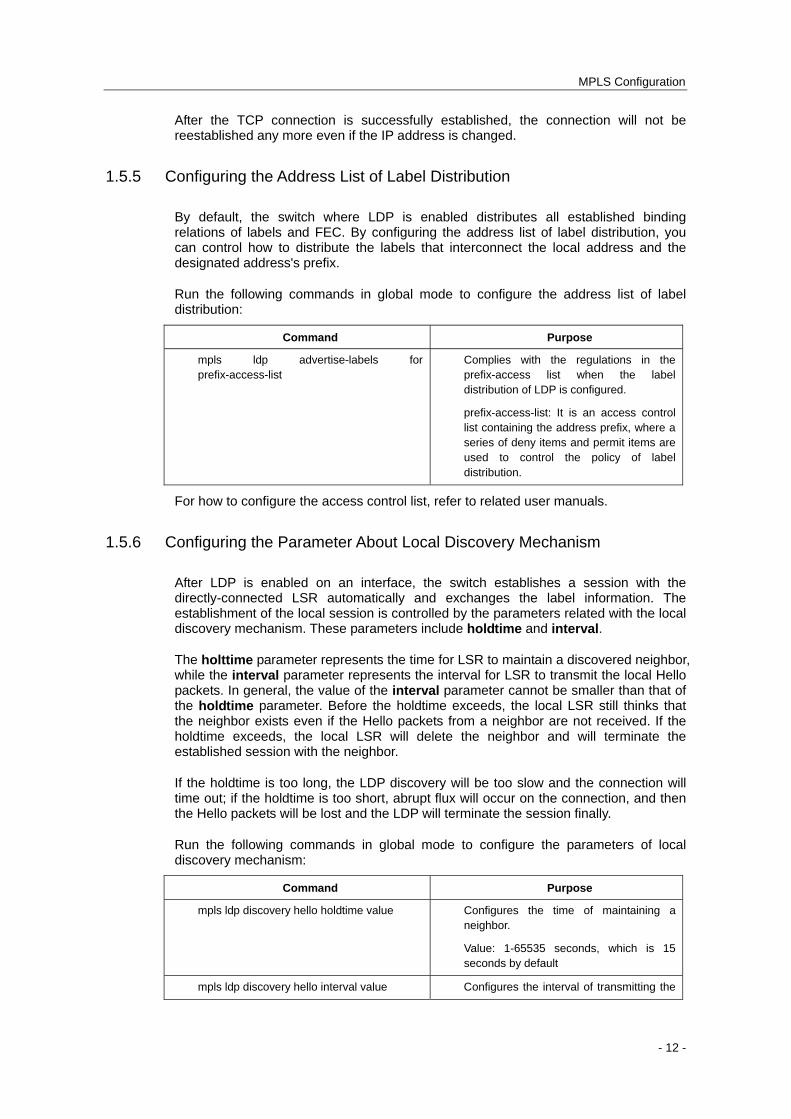
1.5.5 Configuring the Address List of Label Distribution
By default, the switch where LDP is enabled distributes all established binding relations of labels and FEC. By configuring the address list of label distribution, you can control how to distribute the labels that interconnect the local address and the designated address's prefix.
Run the following commands in global mode to configure the address list of label distribution:
Command Purpose
mpls ldp advertise-labels for prefix-access-list
Complies with the regulations in the prefix-access list when the label distribution of LDP is configured.
prefix-access-list: It is an access control list containing the address prefix, where a series of deny items and permit items are used to control the policy of label distribution.
For how to configure the access control list, refer to related user manuals.
1.5.6 Configuring the Parameter About Local Discovery Mechanism
After LDP is enabled on an interface, the switch establishes a session with the directly-connected LSR automatically and exchanges the label information. The establishment of the local session is controlled by the parameters related with the local discovery mechanism. These parameters include holdtime and interval.
The holttime parameter represents the time for LSR to maintain a discovered neighbor, while the interval parameter represents the interval for LSR to transmit the local Hello packets. In general, the value of the interval parameter cannot be smaller than that of the holdtime parameter. Before the holdtime exceeds, the local LSR still thinks that the neighbor exists even if the Hello packets from a neighbor are not received. If the holdtime exceeds, the local LSR will delete the neighbor and will terminate the established session with the neighbor.
If the holdtime is too long, the LDP discovery will be too slow and the connection will time out; if the holdtime is too short, abrupt flux will occur on the connection, and then the Hello packets will be lost and the LDP will terminate the session finally.
Run the following commands in global mode to configure the parameters of local discovery mechanism:
Command Purpose
mpls ldp discovery hello holdtime value Configures the time of maintaining a neighbor.
Value: 1-65535 seconds, which is 15 seconds by default
mpls ldp discovery hello interval value Configures the interval of transmitting the
- 12 -
MPLS Configuration
Hello packets.
Value: 1-65535 seconds, which is 3 seconds by default
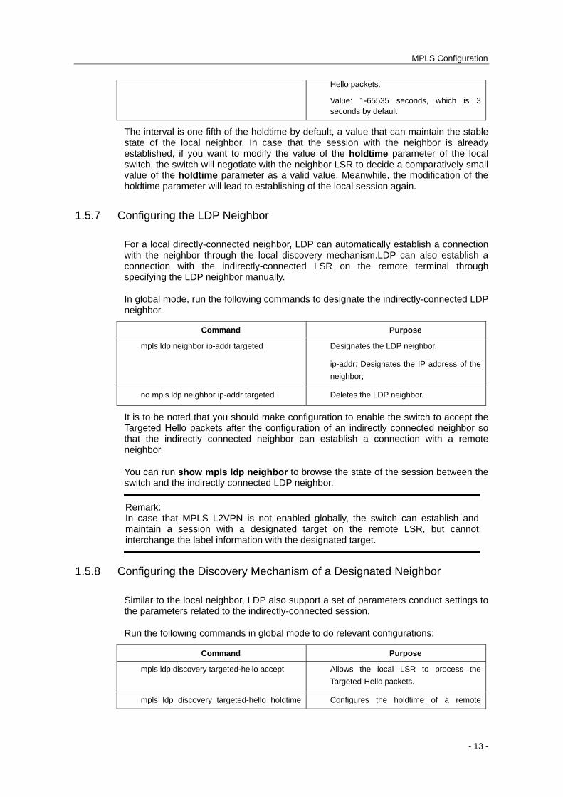
The interval is one fifth of the holdtime by default, a value that can maintain the stable state of the local neighbor. In case that the session with the neighbor is already established, if you want to modify the value of the holdtime parameter of the local switch, the switch will negotiate with the neighbor LSR to decide a comparatively small value of the holdtime parameter as a valid value. Meanwhile, the modification of the holdtime parameter will lead to establishing of the local session again.
1.5.7 Configuring the LDP Neighbor
For a local directly-connected neighbor, LDP can automatically establish a connection with the neighbor through the local discovery mechanism.LDP can also establish a connection with the indirectly-connected LSR on the remote terminal through specifying the LDP neighbor manually.
In global mode, run the following commands to designate the indirectly-connected LDP neighbor.
Command Purpose
mpls ldp neighbor ip-addr targeted Designates the LDP neighbor.
ip-addr: Designates the IP address of the
neighbor;
no mpls ldp neighbor ip-addr targeted Deletes the LDP neighbor.
It is to be noted that you should make configuration to enable the switch to accept the Targeted Hello packets after the configuration of an indirectly connected neighbor so that the indirectly connected neighbor can establish a connection with a remote neighbor.
You can run show mpls ldp neighbor to browse the state of the session between the switch and the indirectly connected LDP neighbor.
Remark: In case that MPLS L2VPN is not enabled globally, the switch can establish and maintain a session with a designated target on the remote LSR, but cannot interchange the label information with the designated target.
1.5.8 Configuring the Discovery Mechanism of a Designated Neighbor
Similar to the local neighbor, LDP also support a set of parameters conduct settings to the parameters related to the indirectly-connected session.
Run the following commands in global mode to do relevant configurations:
Command Purpose
mpls ldp discovery targeted-hello accept Allows the local LSR to process the
Targeted-Hello packets.
mpls ldp discovery targeted-hello holdtime Configures the holdtime of a remote
- 13 -
MPLS Configuration
value session.
Value: 1-65535 seconds, which is 45 seconds by default
mpls ldp discovery targeted-hello interval value
Configures the interval of sending
Targeted-Hello packets of the remote
session.
Value: 1-65535 seconds, which is 15 seconds by default
After a neighbor is detected on the port before the hold time times out, the target hello information from the neighbor is not received, the neighbor will be deleted and the target LDP session with the neighbor will be terminated.
If the target holdtime is too long, the target LDP discovery will be too slow and the connection will time out; if the target holdtime is too short, abrupt flux will occur on the connection, and then the target Hello packets will be lost and the target LDP will terminate the session finally.
1.5.9 Configuring the Holdtime of the Session
After a session between the switch and other LSRs is established, the keepalive packets need be sent regularly to maintain the session.In the case that the holdtime does not exceed, LSR still thinks the session valid even if no Keepalive packets is not received.
Run the following commands in global mode to configure the holdtime of a session:
Command Purpose
mpls ldp holdtime value Configures the Holdtime of the LDP
session.
Value: 1-65535 (the default value is 60
seconds)
During the establishment of a session, LSRs will negotiate the comparatively small value of the holdtime as an effective value.
1.5.10 Force Explicit-Null Label
By default, as to the local direct-through route, LDP notifies the upstream neighbor of the implicit null label so that the upstream neighbor adopts the next to the last hop to pop up the outside label when the upstream neighbor is forwarding the MPLS packets. In order to prevent the next to the last hop from popping out the outside label, you need to take the strategy that uses the explicit null label to replace the outside label and to configure this command.
Note: To enable MPLS L2VPN or MPLS L2VPN on the switch, please make sure that the force explicit-null label is not configured.
You can run the following command in global mode to force the switch to notify the Explicit-Null label.
- 14 -
MPLS Configuration
Command Purpose
mpls ldp explicit-null
[ for prefix-acl [ to peer-acl ] ]
prefix-acl: Means that the ACL list which
complies with the designated prefix will
replace the implicit null label with the
explicit null label and then notify the
upstream LDP neighbor.
peer-acl: Means replacing the implicit null
label with the explicit null label and then
notifying the designated upstream LDP
neighbor.
If mpls ldp explicit-null is configured, the direct-through routes that meet prefix ACL will replace the Implicit-Null label with the Explicit-Null label and notify the upstream neighbors that meet prefix ACL; if prefix-acl is not configured, all direct-through routes will replace the Implicit-Null label with the Explicit-Null label.
1.5.11 Configuring LDP Log Record
LDP supports recording the change of neighbors through the log.
Run the following commands in global mode to enable the LDP log:
Command Purpose
logging ip-addr Enables the systematic log.
ip-addr:Means the address of the log
server.
mpls ldp logging neighbor-changes Enables the LDP log to record
information.
1.5.12 Browsing LDP Information
In global or interface configuration mode, run the following commands to browse the LDP information.
Command Purpose
show mpls ldp bindings Displays the content of the label
database.
show mpls ldp discovery Displays the port list in which all the ports
have the LDP discovery mechanism.
show mpls ldp neighbor Displays the state of the session between
LDP neighbors.
show mpls ldp parameters Displays the current parameters of LDP.
- 15 -
MPLS Configuration
Chapter 2 MPLS L2VPN Configuration
2.1 Overview of MPLS L2VPN
MPLS L2VPN is also called as Virtual Private LAN Service (VPLS) that provides layer-2 virtual private network services on the basis of the MPLS network
BDCOM Ethernet switch series provide L2VPN function that takes the Label Distribution Protocol (LDP) as the signaling protocol.
The switch that gets L2VPN service running is always served as the Provider Edge (PE) equipment of which one end is connected to the Client Edge (CE) equipment and the other end to the MPLS core of the provider to establish the label distribution path with other providers' router (P).The establishment of the label distribution path in the switch is finished by the software control layer while the forwarding of packets is completed by the data layer.As to the packets from the client equipment, the switch conducts the local layer-2 switching, if packets need be forwarded to the MPLS network, adds the MPLS label stack to packets automatically and encapsulates them to the header of the new Ethernet network and then forwards them to the next hop of LSP; as to packets from the MPLS network, the switch first remove their headers and then forwards them according to the Ethernet information carried by original packets.
2.2 Related Concepts of MPLS L2VPN
2.2.1 VFI
Virtual Forwarding Instance (VFI) acts as the bridge to forward layer-2 packets in the switches where L2VPN is enabled. Different from general switches, VFI connects not only common Ethernet interfaces but also PW of the remote VFI.
VFI can plot the broadcast domains in the switch and thus a broadcast packet can be forwarded to all interfaces of VFI.That's the exact reason why VFI corresponds to VLAN of a switch.
2.2.2 Pseudo-Wire
The Pseudo Wire (PW) means the connection between remote VFIs. PW consists of a pair of unidirectional MPLS label distribution paths. Hence, a PW always corresponds to two virtual circuit labels: the VC label generated by local PE and the VC label generated by peer PE. The local VC label that is always carried by the received MPLS packet can be used to represent the corresponding ILM item, while the peer VC label that is always used by the locally transmitted MPLS packet can be used to represent the corresponding FTN item.
The establishment of a PW also requires that the next hop of LSP must be definite.The label that corresponds to the next hop is called as the tunnel label. When an MPLS packet is being transmitted, the VC label and then the tunnel label will be added to the
- 16 -
MPLS Configuration
label stack of the MPLS packet and a decision as to where the packet to go will be made before the reciprocal twice hop.
2.2.3 L2VPN Network Without Loopback
In point-to-multipoint mode, VPLS requires that full-mesh connections should be established among all PEs. A PW thus exists between any two PEs.When packets are forwarded, the split-horizon strategy is carried out and the broadcast packets that PE receives from PW will not be forwarded to PW.In this case, PE need not start STP to avoid loopback.
Note: The LS12GE-MPLS card of the BDCOM hi-end switch only supports the point-to-point MPLS L2VPN.
2.3 MPLS L2VPN Configuration
2.3.1 MPLS L2VPN Configuration Task List
Enabling MPLS L2VPN
Creating VFI
Binding VFI to VLAN Interface
Configuring the Incoming VFI Interface
Configuring a Static VC Label
Browsing L2VPN Information
2.3.2 Enabling MPLS L2VPN
Run the following commands in global mode to enable L2VPN:
Command Purpose
mpls l2vpn Start L2VPNEnables L2VPN.
no mpls l2vpn Shuts down L2VPN.
2.3.3 Creating VFI
After L2VPN is enabled, VFI need be created and bound to a VLAN interface, which means that the interface of this VLAN will be connected to a client device.
Run the following command in global mode to create a VFI:
Command Purpose
mpls vfi vfi-name Creates VFI and enters the VFI
- 17 -
MPLS Configuration
[ ptop | vpls ] configuration mode.
Vfi-name: Means the name of VFI.
ptop: Means that VFI is in point-to-point
mode and there is only one remote
neighbor.
vpls: means that VFI is in
point-to-multipoint mode.
In VFI configuration mode, you can run the following commands to configure relevant parameters:
Command Purpose
pwid value Configures the PW ID used by VFI.
neighbor peer-addr encapsulation mpls Designates the VFI neighbor.
peer-addr: IP address of a neighbor
PW ID is the ID that is used by VFI when the fake line is established. Different VFIs have different PW IDs. The same PW ID must be used to identify the same VFI among VFI neighbors; otherwise, the PW cannot be established. After a PW ID is designated for a VFI, the ID cannot be modified. If you want to modify the PW ID of a VFI, you have to delete the VFI and then reestablish it.
It is noted that you cannot establish the designated target session between two LSRs only by designating the VFI neighbor. You also need to designate the VFI neighbor as the LDP neighbor through the mpls ldp neighbor command.
Note: 1. Only one neighbor can be designated for the point-to-point VFI. 2. In multipoint mode, each PE device requires a complete VFI neighbor list to be designated so that a full-mesh connection can be established.
2.3.4 Binding VFI to VLAN Interface
Note: As to BDCOM hi-end switches of version 4.0.1A and previous version, do not configure the IP address on the VLAN interface where VFI is bound.
After VFI is created, you need to bind it to the VLAN interface to show that the physical interface in VLAN is used to connect the client device.
Run the following command in VLAN interface configuration mode to bind a VFI:
Command Purpose
mpls l2vpn vfi vfi-name Binds VFI to an interface.
vfi-name: Means the name of bound VFI.
Note:
- 18 -
MPLS Configuration
VFI corresponds to VLAN interface one by one, that is to say, one VFI can be bound to only one VLAN interface.
2.3.5 Configuring Incoming VFI Interface
When using BDCOM LS12GE-MPLS card, except that VFI need be bound to the VLAN interface, the settings of the physical interfaces in this VLAN to be access interfaces of VFI also need be conducted.
Run the following command in physical interface configuration mode to add interfaces to a VFI:
Command Purpose
switchport mpls l2vpn vfi vfi-name Sets an interface to be the access
interface of the designated VFI.
vfi-name:Means the name of the bound
VFI.
BDCOM LS12GE-MPLS card supports configuring multiple physical interfaces in a VFI as the access interfaces simultaneously. You can run show vlan id to browse the physical interface set in a VLAN which correspond to VFI and select the access interface to conduct configuration.One physical interface can be configured as the access interface of multiple VFIs at the same time after you run switchport mpls l2vpn vfi on each VFI.
Note: The configuration of the VFI access interface cannot change the VLAN attributes of a physical interface, but you have to make sure that the physical interface has been added to the VLAN corresponding to VFI.
To cancel the configuration of the VFI access interface, please run no switchport mpls l2vpn vfi in physical interface configuration mode.It should be paid attention that the physical interface will be removed from all VFIs if the VFI name is not entered.
2.3.6 Configuring a Static VC Label
Like MPLS, L2VPN also supports static information forwarding.
Run the following commands in global mode to configure static information forwarding for VFI:
Command Purpose
mpls static vfi vfi-name incoming-label
output peer-addr outgoing-label
Configures static VFI ILM items.
Vfi-name: Means the name of VFI.
incoming-label: Incoming label whose
range is the static label range
peer-addr: means the address of the VFI
neighbor
Outgoing-label: stands for the outgoing label, whose range is from 16 to 1048575.
- 19 -
MPLS Configuration
Remark: A static VFI item is used to stand for a PW connection, while incoming-label and outgoing-label stand for the local VC label and the peer VC label respectively.The static VFI item takes effect only when PW is effective at the next hop.
2.3.7 Browsing L2VPN Information
In global or interface configuration mode, run the following commands to browse the information about MPLS L2VPN.
Command Purpose
show mpls forwarding-table pwid value Displays the ILM information that
corresponds to the designated PW ID in
the label forwarding base. The value
parameter ranges from 1 to 4294967295.
show mpls ftn-table vfi vfi-name Browses the forwarding items in the
designated VFI.
vfi-name: Means the name of VFI.
show mpls ldp bindings vfi vfi-name Browses the information about VFI-related
label binding.
show mpls l2vpn vfi Browses the states of all VFIs.
show mpls l2vpn pw
[ pwid | neighbor peer-addr |
interface interface-name | detail ]
Browses PW information.
pwid: Designates PW ID.
neighbor peer-addr: Designates a
neighbor.
interface interface-name: Stands for the
type and name of the interface.
detail: Stands for detailed PW information.
2.4 MPLS L2VPN Configuration Example
2.4.1 Point-to-Point L2VPN Configuration Example
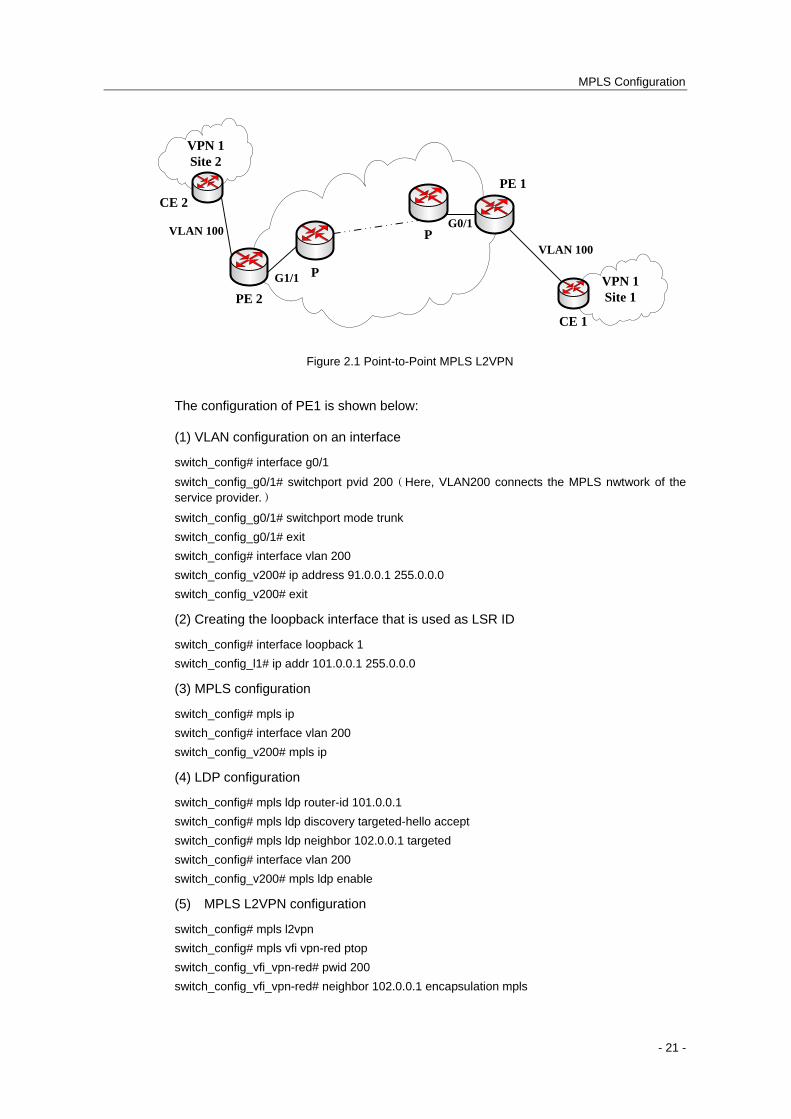
Figure 2.1 shows a typical point-to-point MPLS L2VPN network frame:
- 20 -
MPLS Configuration
VPN 1Site 1
VPN 1Site 2
PE 2
PE 1
CE 2
CE 1
P
P
G1/1
G0/1VLAN 100
VLAN 100
Figure 2.1 Point-to-Point MPLS L2VPN
The configuration of PE1 is shown below:
(1) VLAN configuration on an interface
switch_config# interface g0/1
switch_config_g0/1# switchport pvid 200(Here, VLAN200 connects the MPLS nwtwork of the service provider.)
switch_config_g0/1# switchport mode trunk
switch_config_g0/1# exit
switch_config# interface vlan 200
switch_config_v200# ip address 91.0.0.1 255.0.0.0
switch_config_v200# exit
(2) Creating the loopback interface that is used as LSR ID
switch_config# interface loopback 1
switch_config_l1# ip addr 101.0.0.1 255.0.0.0
(3) MPLS configuration
switch_config# mpls ip
switch_config# interface vlan 200
switch_config_v200# mpls ip
(4) LDP configuration
switch_config# mpls ldp router-id 101.0.0.1
switch_config# mpls ldp discovery targeted-hello accept
switch_config# mpls ldp neighbor 102.0.0.1 targeted
switch_config# interface vlan 200
switch_config_v200# mpls ldp enable
(5) MPLS L2VPN configuration
switch_config# mpls l2vpn
switch_config# mpls vfi vpn-red ptop
switch_config_vfi_vpn-red# pwid 200
switch_config_vfi_vpn-red# neighbor 102.0.0.1 encapsulation mpls
- 21 -
MPLS Configuration
switch_config_vfi_vpn-red# exit
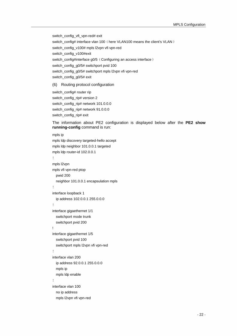
switch_config# interface vlan 100(here VLAN100 means the client’s VLAN)
switch_config_v100# mpls l2vpn vfi vpn-red
switch_config_v100#exit
switch_config#interface g0/5(Configuring an access interface)
switch_config_g0/5# switchport pvid 100
switch_config_g0/5# switchport mpls l2vpn vfi vpn-red
switch_config_g0/5# exit
(6) Routing protocol configuration
switch_config# router rip
switch_config_rip# version 2
switch_config_rip# network 101.0.0.0
switch_config_rip# network 91.0.0.0
switch_config_rip# exit
The information about PE2 configuration is displayed below after the PE2 show running-config command is run:
mpls ip
mpls ldp discovery targeted-hello accept
mpls ldp neighbor 101.0.0.1 targeted
mpls ldp router-id 102.0.0.1
!
mpls l2vpn
mpls vfi vpn-red ptop
pwid 200
neighbor 101.0.0.1 encapsulation mpls
!
interface loopback 1
ip address 102.0.0.1 255.0.0.0
!
interface gigaethernet 1/1
switchport mode trunk
switchport pvid 200
!
interface gigaethernet 1/5
switchport pvid 100
switchport mpls l2vpn vfi vpn-red
!
interface vlan 200
ip address 92.0.0.1 255.0.0.0
mpls ip
mpls ldp enable
!
interface vlan 100
no ip address
mpls l2vpn vfi vpn-red
- 22 -

MPLS Configuration
!
router rip
version 2
network 102.0.0.0
network 92.0.0.0
- 23 -
MPLS Configuration
Chapter 3 MPLS L3VPN Configuration
3.1 Overview of MPLS L3VPN
MPLS L3VPN can also be called as MPLS VRF VPN or MPLS BGP VPN, a combination between MPLS and VRF.
In general, one VPN comprises a team of client networks that share a public routing table on the ISP's routers.Each client network is connected to the interface of the network devices of ISP, while ISP's device will relate each interface to a VPN routing table.One VPN routing table is also called as a VRF (VPN Routing /Forwarding table).
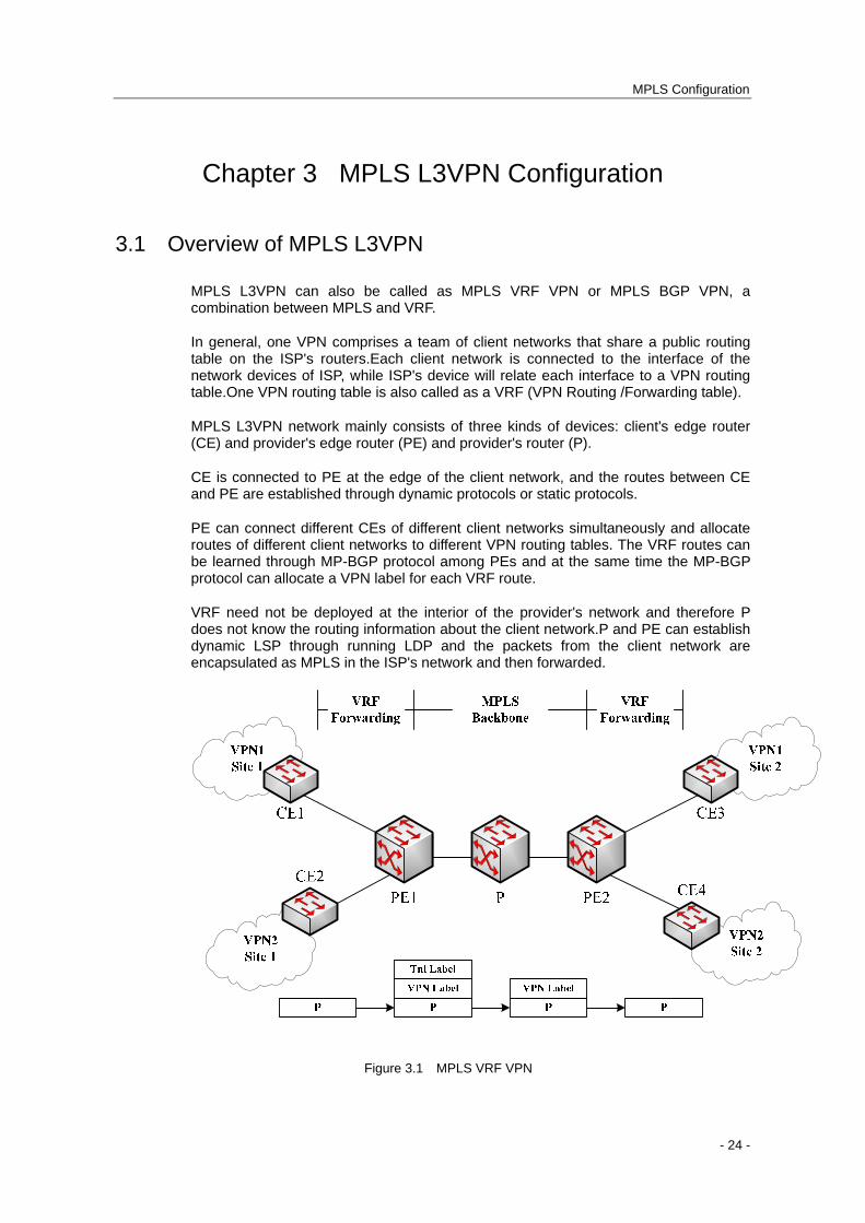
MPLS L3VPN network mainly consists of three kinds of devices: client's edge router (CE) and provider's edge router (PE) and provider's router (P).
CE is connected to PE at the edge of the client network, and the routes between CE and PE are established through dynamic protocols or static protocols.
PE can connect different CEs of different client networks simultaneously and allocate routes of different client networks to different VPN routing tables. The VRF routes can be learned through MP-BGP protocol among PEs and at the same time the MP-BGP protocol can allocate a VPN label for each VRF route.
VRF need not be deployed at the interior of the provider's network and therefore P does not know the routing information about the client network.P and PE can establish dynamic LSP through running LDP and the packets from the client network are encapsulated as MPLS in the ISP's network and then forwarded.
Figure 3.1 MPLS VRF VPN
- 24 -
MPLS Configuration
The packets from the client network are first forwarded from CE to an interface of PE, PE then search the relevant VRF routing table according to the VRF configuration of the interface and find the route according to the destination IP address of these packets.In case that an MP-BGP session among PEs is already created, PE finds that the packets from the client network need be forwarded to the remote PE. You need first add the VPN label generated by MP-BGP to the front of the IP header of the client packet, then PE searches the real next-hop P of the peer PE on LSP and adds the next-hop label to the outside of the VPN label.In the process from PE to the next-to-the-last P, the VPN label and the tunnel label always exist before the IP header of the client packet.When the packets arrive at the next-to-the-last-hop P, P removes the outside labels from the packets and then transmits the packets with the VPN label to the destination PE, while the destination PE, according to the VPN label, forwards the client packets to CE.
Remark: The Ethernet switches that support VRF can function as MCE devices to be deployed between PE and client network so as to save the port resources of PE.Please see Multi-VRF CE Configuration of BDCOM Ethernet Switch.
Note: On a PE device, you can configure MPLS L2VPN and MPLS L3VPN at the same time.
3.2 MPLS L3VPN Configuration
3.2.1 MPLS L3VPN Configuration Task List
Configuring MPLS
Configuring LDP
Configuring VRF
Configuring a VPN Route
Configuring a Route Between PE and P
Configuring a Route Between PEs
3.2.2 Configuring MPLS
Run the following commands one by one to enable the MPLS function of a switch:
Command Purpose
Switch# configure Enters the global configuration mode of the
switch.
Switch_config# mpls ip Enables MPLS in global mode.
Switch_config# interface vlan id Creates a VLAN interface and enters the VLAN
- 25 -
MPLS Configuration
configuration mode.
Switch_config_intf# mpls ip Enables the MPLS function of a VLAN
interface.
Switch_config_intf# exit Exits from Vlan interface configuration mode.
Switch_config# show mpls interface Browses the state of the MPLS interface.
3.2.3 Configuring LDP
Run the following commands one by one to enable the LDP function of a switch:
Command Purpose
Switch# configure Enters the global configuration mode of the
switch.
Switch_config# mpls ldp router-id A.B.C.D Configures the ID of the LDP router.
Switch_config# interface vlan id Enters the VLAN configuration mode.
Switch_config_intf# mpls ldp enable Enables LDP of the VLAN interface.
Switch_config_intf# exit Exits from the interface configuration mode.
3.2.4 Configuring VRF
To configure one or multiple VRFs and bind the L3 interface to VRF, run the following commands:
Command Purpose
Switch# configure Enters the switch configuration mode.
Switch_config# ip vrf vrf-name Creates VRF and enters the VRF configuration mode.
Vrf-name: VRF name with up to 16 characters
Switch_config_vrf# rd route-distinguisher Sets the route distinguisher of VRF.
route-distinguisher: Stands for the distinguisher of the route. It consists of autonomous domain ID and random numbers, or IP and random numbers.
Switch_config_vrf# route-target
{ export | import | both }
route-target-extened-community
Creates the expanded VPN attributes of VRF input and output objects.
route-target-extended-community: Stands for the distinguisher of the route. It consists of autonomous domain ID and random numbers, or IP and random numbers.
Switch_config_vrf# interface intf-name Enters the interface configuration mode.
intf-name: Stands for the name of an interface.
Switch_config_intf# ip vrf forwarding vrf-name Relates the L3 interface with VRF.
- 26 -
MPLS Configuration
vfi-name: Means the name of VRF.
Switch_config_intf# exit Exits from interface configuration mode.
Switch_config# ip exf Enables the routing of ip hardware.
Switch_config# show ip vrf
[ brief | detail | interface ] [ vrf-name ]
Browses the VRF information.
Switch_config# no ip vrf vrf-name Deletes the configured VRF and the relation between VRF and the L3 interface.
vfi-name: Means the name of VRF.
Switch_config_intf# no ip vrf forwarding
[ vrf-name ]
Deletes the relation between the L3 interface and VRF.
3.2.5 Configuring a VPN Route
The VPN route refers to the route between PE and CE. The following configurations take the OSPF protocol as an example. These configurations based on OSPF are similar to these configurations based on RIP or BEIGRP.
Remark: The VPN route can be established between PE and MCE through the EBGP protocol.Please see Multi-VRF CE Configuration of BDCOM Ethernet Switch.
Refer to the following steps to create a VPN route between PE and CE.
Command Purpose
Switch# configure Enters the switch configuration mode.
Switch_config# router ospf
process-id vrf vrf-name
Starts the OSPF-VRF route and enters the
configuration mode.
Switch_config_ospf# network network-number
network-mask area area-id
Defines the OSPF network, mask and area ID.
Switch_config_ospf# redistribute bgp ASN Forwards the designated BGP network to the
OSPF network.
Switch_config_ospf# exit Exits from the OSPF configuration mode.
Switch_config# show ip ospf Browses the information about the OSPF
protocol.
Switch_config# no router ospf process-id Deletes the OSPF-VRF routing configuration.
3.2.6 Configuring a Route Between PE and P
A route can be established between PE and P through dynamic routing protocol such as OSPF, RIP and BEIGRP, so can a static route.The following description takes the OSPF protocol as an example.
Command Purpose
- 27 -
MPLS Configuration
Switch# configure Enters the switch configuration mode.
Switch_config# router ospf
process-id
Starts the OSPF-VRF route and enters the
configuration mode.
Switch_config_ospf# network network-number
network-mask area area-id
Defines the OSPF network, mask and area ID.
Switch_config_ospf# exit Exits from the OSPF configuration mode.
Switch_config# show ip ospf Browses the information about the OSPF
protocol.
Switch_config# no router ospf process-id Deletes the OSPF-VRF routing configuration.
3.2.7 Configuring a BGP Route Between PEs
Refer to the following steps to create a MP-BGP route between PEs.
Command Purpose
Switch# configure Enters the switch configuration mode.
Switch_config# router bgp autonomous-system-number
Starts the BGP protocol by designating
autonomous system number and enters the
BGP configuration mode.
Switch_config_bgp# bgp log-neighbor-changes Starts the record about BGP neighbor change.
Switch_config_bgp# neighbor address remote-as ASN
Configures the BGP neighbor and the
autonomous system number of a neighbor.
Switch_config_bgp# neighbor address update-source intf-name
Configures the interface that will be used to
connect a BGP neighbor.
Switch_config_bgp# address-family vpnv4 Enters the configuration mode of BGP VPN.
Switch_config_bgp_vpnv4# neighbor address activate
Activates a neighbor in VPNV4.
Switch_config_bgp_vpnv4# bgp redistribute-internal
Redistributes the VPNV4 route to the routing
protocol of internal gateway.
Switch_config_bgp_vpnv4# exit-address-family Exits from the VPNV4 configuration mode.
Switch_config_bgp# address-family ipv4 vrf vrf-name
Enters the configuration mode of VRF
address-family.
Switch_config_bgp_af# bgp redistribute-internal Redistributes the VRF route to the routing
protocol of internal gateway.
Switch_config_bgp_af# redistribute ospf ospf-process-id
Redistributes the OSPF routing information to
the BGP network.
Switch_config_bgp_af# network network-number / prefix-len
Configures the network number and the mask
‘s length that are distributed by BGP.
Switch_config_bgp_af# exit-address-family Exits from the configuration mode of VRF
address-family.
- 28 -
MPLS Configuration
Switch_config_bgp# exit Exits from the BGP configuration mode.
Switch_config# show ip bgp vpnv4 [ * | all | rd | vrf ]
Browses the BGP-VRF routing information and
the label’s state.
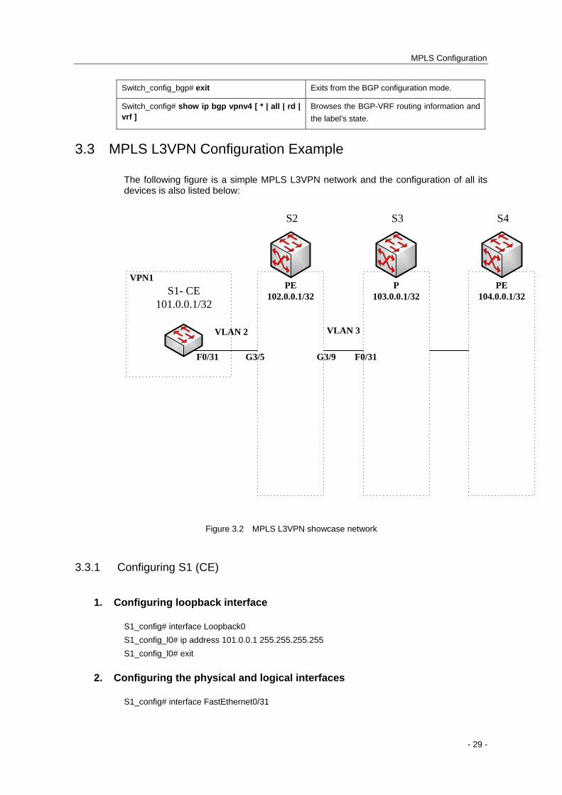
3.3 MPLS L3VPN Configuration Example
The following figure is a simple MPLS L3VPN network and the configuration of all its devices is also listed below:
S2 S3 S4
S1- CE101.0.0.1/32
PE102.0.0.1/32
P103.0.0.1/32
PE104.0.0.1/32
F0/31
VLAN 2
G3/5 G3/9 F0/31
VLAN 3
VPN1
Figure 3.2 MPLS L3VPN showcase network
3.3.1 Configuring S1 (CE)
1. Configuring loopback interface
S1_config# interface Loopback0
S1_config_l0# ip address 101.0.0.1 255.255.255.255
S1_config_l0# exit
2. Configuring the physical and logical interfaces
S1_config# interface FastEthernet0/31
- 29 -
MPLS Configuration
S1_config_f0/31# switchport pvid 2
S1_config_f0/31# exit
S1_config# interface VLAN2
S1_config_v2# ip address 92.0.0.1 255.0.0.0
S1_config_v2# exit
S1_config# vlan 1-3
3. Configuring the OSPF routing protocol
S1_config# router ospf 1
S1_config_ospf_1# network 92.0.0.0 255.0.0.0 area 0
S1_config_ospf_1# network 101.0.0.1 255.255.255.255 area 0
S1_config_ospf_1# exit
3.3.2 Configuring S2 (PE)
1. Configuring global MPLS
S2_config# mpls ip
2. Configuring the global attributes of LDP
S2_config# mpls ldp router-id 102.0.0.1
3. Creating VRF
S2_config# ip vrf vpn1
S2_config_vrf_vpn1# rd 100:1
S2_config_vrf_vpn1# route-target export 100:1
S2_config_vrf_vpn1# route-target import 100:1
S2_config_vrf_vpn1# exit
4. Creating the loopback interface
S2_config# interface Loopback0
S2_config_l0# ip address 102.0.0.1 255.255.255.255
S2_config_l0# exit
5. Configuring the physical interface
S2_config# interface GigaEthernet3/5
S2_config_g3/5# switchport pvid 2
S2_config_g3/5# exit
S2_config# interface GigaEthernet3/9
S2_config_g3/9# switchport pvid 3
S2_config_g3/9# exit
- 30 -
MPLS Configuration
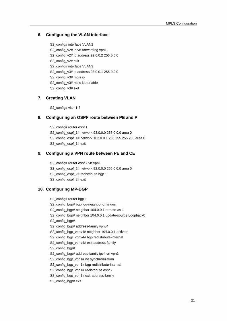
6. Configuring the VLAN interface
S2_config# interface VLAN2
S2_config_v2# ip vrf forwarding vpn1
S2_config_v2# ip address 92.0.0.2 255.0.0.0
S2_config_v2# exit
S2_config# interface VLAN3
S2_config_v3# ip address 93.0.0.1 255.0.0.0
S2_config_v3# mpls ip
S2_config_v3# mpls ldp enable
S2_config_v3# exit
7. Creating VLAN
S2_config# vlan 1-3
8. Configuring an OSPF route between PE and P
S2_config# router ospf 1
S2_config_ospf_1# network 93.0.0.0 255.0.0.0 area 0
S2_config_ospf_1# network 102.0.0.1 255.255.255.255 area 0
S2_config_ospf_1# exit
9. Configuring a VPN route between PE and CE
S2_config# router ospf 2 vrf vpn1
S2_config_ospf_2# network 92.0.0.0 255.0.0.0 area 0
S2_config_ospf_2# redistribute bgp 1
S2_config_ospf_2# exit
10. Configuring MP-BGP
S2_config# router bgp 1
S2_config_bgp# bgp log-neighbor-changes
S2_config_bgp# neighbor 104.0.0.1 remote-as 1
S2_config_bgp# neighbor 104.0.0.1 update-source Loopback0
S2_config_bgp#
S2_config_bgp# address-family vpnv4
S2_config_bgp_vpnv4# neighbor 104.0.0.1 activate
S2_config_bgp_vpnv4# bgp redistribute-internal
S2_config_bgp_vpnv4# exit-address-family
S2_config_bgp#
S2_config_bgp# address-family ipv4 vrf vpn1
S2_config_bgp_vpn1# no synchronization
S2_config_bgp_vpn1# bgp redistribute-internal
S2_config_bgp_vpn1# redistribute ospf 2
S2_config_bgp_vpn1# exit-address-family
S2_config_bgp# exit
- 31 -
MPLS Configuration
- 32 -
11. Enabling the routing of ip hardware subnet
S2_config# ip exf
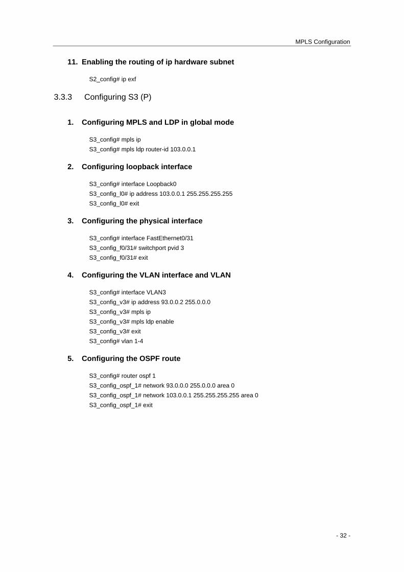
3.3.3 Configuring S3 (P)
1. Configuring MPLS and LDP in global mode
S3_config# mpls ip
S3_config# mpls ldp router-id 103.0.0.1
2. Configuring loopback interface
S3_config# interface Loopback0
S3_config_l0# ip address 103.0.0.1 255.255.255.255
S3_config_l0# exit
3. Configuring the physical interface
S3_config# interface FastEthernet0/31
S3_config_f0/31# switchport pvid 3
S3_config_f0/31# exit
4. Configuring the VLAN interface and VLAN
S3_config# interface VLAN3
S3_config_v3# ip address 93.0.0.2 255.0.0.0
S3_config_v3# mpls ip
S3_config_v3# mpls ldp enable
S3_config_v3# exit
S3_config# vlan 1-4
5. Configuring the OSPF route
S3_config# router ospf 1
S3_config_ospf_1# network 93.0.0.0 255.0.0.0 area 0
S3_config_ospf_1# network 103.0.0.1 255.255.255.255 area 0
S3_config_ospf_1# exit


![[MPLS Configuration Guide] - D-Link Academyacademy.dlink.com/temp/exam_Issue/230/MPLS Configuration Guide… · MPLS Configuration Guide Multiprotocol Label Switching (MPLS) MPLS](https://img.pdfslide.us/doc/110x75/5a815ac47f8b9ada388cfeea/mpls-configuration-guide-d-link-configuration-guidempls-configuration-guide.jpg)


![MPLS VPN Configuration on IOS Platforms[1]](https://img.pdfslide.us/doc/110x75/5500c63e4a7959995f8b4d29/mpls-vpn-configuration-on-ios-platforms1.jpg)