Atlantic Energy Gateway Transmission Modeling Study
Report
A Study of Transmission Upgrade Options For
Atlantic Canadian Utilities
March 30, 2012
AEG Transmission Modeling Study
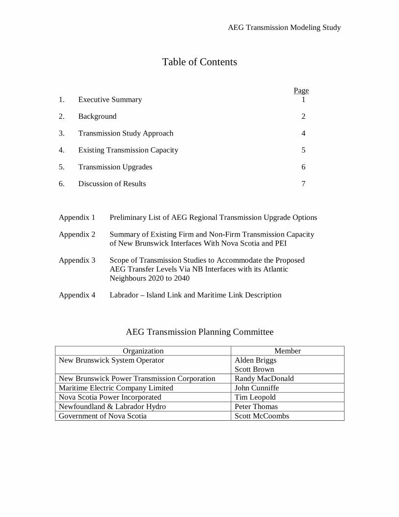
Table of Contents
Page 1. Executive Summary 1
2. Background 2
3. Transmission Study Approach 4
4. Existing Transmission Capacity 5
5. Transmission Upgrades 6
6. Discussion of Results 7
Appendix 1 Preliminary List of AEG Regional Transmission Upgrade Options
Appendix 2 Summary of Existing Firm and Non-Firm Transmission Capacity of New Brunswick Interfaces With Nova Scotia and PEI
Appendix 3 Scope of Transmission Studies to Accommodate the Proposed AEG Transfer Levels Via NB Interfaces with its Atlantic Neighbours 2020 to 2040
Appendix 4 Labrador – Island Link and Maritime Link Description
AEG Transmission Planning Committee
Organization Member New Brunswick System Operator Alden Briggs
Scott Brown New Brunswick Power Transmission Corporation Randy MacDonald Maritime Electric Company Limited John Cunniffe Nova Scotia Power Incorporated Tim Leopold Newfoundland & Labrador Hydro Peter Thomas Government of Nova Scotia Scott McCoombs
AEG Transmission Modeling Study
Page 1
Atlantic Energy Gateway Transmission Modeling Study Report A Study of Transmission Upgrade Options for Atlantic Canadian Utilities 1. Executive Summary
The Atlantic Energy Gateway (AEG) project is a regional initiative of the federal government, the Atlantic provincial governments, electric utilities of Atlantic Canada and the system operators in New Brunswick and Nova Scotia. The objective of the AEG project is to contribute to the development of Atlantic Canada's clean energy resources by identifying the opportunities and assisting in evaluating the advantages of the region’s substantial and diversified renewable energy potential for wind, tidal, solar, biomass/biofuels, geothermal and hydro. At the heart of the AEG project is a resource assessment of the Atlantic Canada integrated regional power supply systems through the development of a representative model of the electricity system. That model was used to evaluate the current operation of the system as well as develop scenarios that integrate increasing amounts of renewable and non-emitting energy sources for domestic and export loads.
A tighter integration of the Atlantic Canada electrical system will lead to increased opportunities for inter-provincial energy trade. These opportunities are enhanced by implementing a number of key transmission upgrade options within and between provinces, not just facilities at the borders. Adequate transmission capacity is a key element to generation expansion. Lack of transmission capacity leads to congestion and results in sub-optimal generation dispatch. This results in increased electricity production costs through curtailment of low cost generation and dispatch of more costly alternatives. The addition of transmission capacity will reduce marginal electricity costs across the region. Various potentially desirable transmission upgrade options were identified by the Transmission Planning Committee. Studies performed using the integrated resource model, under the direction of the AEG Resource Development Modeling group, identified the key interfaces as those between New Brunswick and Nova Scotia, and New Brunswick and Prince Edward Island. These interfaces have been previously studied at a high level to determine their approximate transfer capabilities and the costs to upgrade transmission facilities into this area. This information was provided to the AEG Resource Development Modeling group. As the resource development plan becomes known and the Atlantic Canada electricity system evolves, more comprehensive transmission studies will be required to assess the impact and define the transmission upgrades necessary to implement the plan.
AEG Transmission Modeling Study
Page 2
2. Background
The objective of the Atlantic Energy Gateway (AEG) project is to contribute to the development of Atlantic Canada's clean energy resources by identifying the opportunities, and assisting in evaluating the advantages of the region’s substantial and diversified renewable energy potential for wind, tidal, solar, biomass/biofuels, geothermal and hydro.
The AEG project is a collaboration of the four Atlantic Canada provincial energy departments, electric utilities representing each Atlantic Canada province, Atlantic Canada Opportunities Agency and Natural Resources Canada. The work includes planning for generation, transmission, and system operation, as well as electricity markets, supply chain development, research and development and regulatory improvements. The AEG project is an initiative sponsored by the government of Canada to encourage the development of additional clean and renewable energy supplies in Atlantic Canada.
A major component of the AEG work plan is the undertaking of a series of studies designed to provide a plan for the future development of the electrical system. This plan is widely known as an Integrated Resource Plan (IRP). The IRP is a resource assessment of the Atlantic Canada integrated regional power supply systems through the development of a representative model of the electricity system. The model is used to evaluate the current operation of the system as well as develop scenarios that integrate increasing amounts of generation, including renewable and non-emitting energy sources, for supply to domestic and export loads.
A tighter integration of the Atlantic Canada electrical system will lead to increased opportunities for inter-provincial energy trade. These opportunities may be enhanced by implementing a number of key transmission upgrade options within and between provinces. Adequate transmission capacity is a key element to generation expansion.
The purpose of the Transmission Modeling Study, under the direction of the Transmission Planning Committee, is to quantify the increased inter-provincial capacity that would be achieved by a number of key transmission upgrade options within Atlantic Canada. The study also provides estimates of the cost of each of the options. The results of the study are anticipated to provide information that can be used by Atlantic Canadian governments and utilities in developing and executing energy related policies that will be based on region-wide analyses. The study will develop a greater understanding of the electricity system costs and benefits to guide the policy decision making process with the best information available.
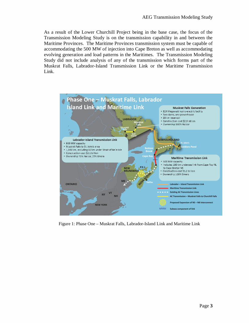
For the purposes of the IRP, Phase I of the Lower Churchill Project is deemed to be in the base case. This consists of the Muskrat Falls generation facility, the Labrador-Island Transmission Link and the Maritime Transmission Link (Figure 1). This project delivers 500 MW via the Maritime Transmission Link to Cape Breton.
AEG Transmission Modeling Study
Page 3
As a result of the Lower Churchill Project being in the base case, the focus of the Transmission Modeling Study is on the transmission capability in and between the Maritime Provinces. The Maritime Provinces transmission system must be capable of accommodating the 500 MW of injection into Cape Breton as well as accommodating evolving generation and load patterns in the Maritimes. The Transmission Modeling Study did not include analysis of any of the transmission which forms part of the Muskrat Falls, Labrador-Island Transmission Link or the Maritime Transmission Link.
Figure 1: Phase One – Muskrat Falls, Labrador-Island Link and Maritime Link
AEG Transmission Modeling Study
Page 4
3. Transmission Study Approach
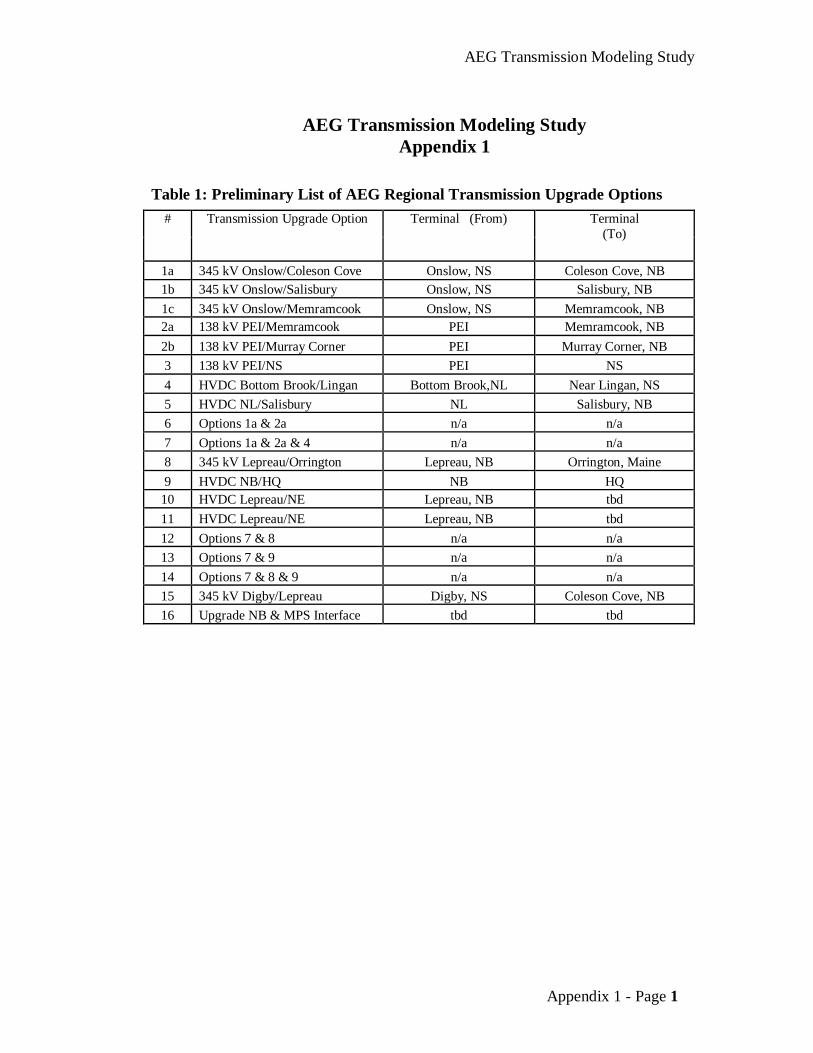
A Transmission Planning Committee representing governments and utilities of Atlantic Canadian provinces was formed to coordinate the efforts of the AEG transmission study. This Transmission Planning Committee was chaired by the New Brunswick System Operator (NBSO). In Phase I of the transmission study, various potentially desirable transmission upgrade options were identified by the Transmission Planning Committee. This list is provided in Appendix 1. These transmission upgrade options were to be studied at a high level to determine their approximate transfer capabilities and associated cost. These transfer capabilities and costs were then to feed into the associated IRP study.
In Phase II of the transmission study, comprehensive transmission studies were to be preformed on the viable transmission options flowing from the IRP.
The AEG Resource Development Modeling group contracted with Ventyx to do the resource study. Ventyx’s task was to develop a system model to be used in a series of production cost simulations using their planning software (Strategist). These studies were completed under the direction of the AEG Resource Development Modeling group. Initially, Ventyx studied two scenarios. The first scenario, the ‘Expanded Transmission Capability’ option, assumed that transmission capacity was upgraded to achieve higher interface capabilities as follows:
NB ← NS = 800 MW NB → NS = 800 MW NB ← PEI = 350 MW NB → PEI = 350 MW
The higher interface capabilities between NB, NS and PEI do not exist today. To achieve these levels, additional transmission infrastructure is required. These Transmission Upgrades are discussed in Section 5.
The second scenario, the ‘Limited Transmission Capability’ option, assumed that transmission capacity is as it exists today. Further detail of existing transmission interface capacity is included in section 4 and in Appendix 2. The production modeling process identified the key interfaces as those between New Brunswick and Nova Scotia and New Brunswick and Prince Edward Island. These interfaces have been previously studied at a high level to determine their approximate transfer capabilities and associated cost. This information was provided to the AEG Resource Development Modeling group. At this time, it is unknown if there is a requirement to study any of the other transmission projects identified in Appendix 1.
AEG Transmission Modeling Study
Page 5
4. Existing Transmission Capacity
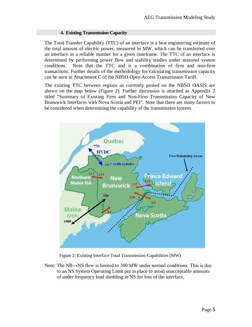
The Total Transfer Capability (TTC) of an interface is a best engineering estimate of the total amount of electric power, measured in MW, which can be transferred over an interface in a reliable manner for a given timeframe. The TTC of an interface is determined by performing power flow and stability studies under seasonal system conditions. Note that the TTC and is a combination of firm and non-firm transactions. Further details of the methodology for calculating transmission capacity can be seen in Attachment C of the NBSO Open Access Transmission Tariff.
The existing TTC between regions as currently posted on the NBSO OASIS are shown on the map below (Figure 2). Further discussion is attached as Appendix 2 titled “Summary of Existing Firm and Non-Firm Transmission Capacity of New Brunswick Interfaces with Nova Scotia and PEI”. Note that there are many factors to be considered when determining the capability of the transmission system.
Figure 2: Existing Interface Total Transmission Capabilities (MW)
Note: The NB→NS flow is limited to 300 MW under normal conditions. This is due to an NS System Operating Limit put in place to avoid unacceptable amounts of under frequency load shedding in NS for loss of the interface.
AEG Transmission Modeling Study
Page 6
5. Transmission Upgrades
The production modeling process identified the key interfaces as being those between:
1. New Brunswick and Nova Scotia, and 2. New Brunswick and Prince Edward Island
These interfaces have been previously studied at a high level to determine their approximate transfer capabilities and associated cost. A summary of the findings from these previous studies follow.
The New Brunswick-Nova Scotia Interface The NB-NS interface was studied by NB Power and NS Power in 2010. The study was prompted by the desire to investigate the options to increase the total transfer capabilities between NB and NS. The study team examined the options necessary to expand the 345 kV transmission system between the provinces. This study included both analysis of transmission capacity and capital cost for proposed infrastructure additions. The transmission reinforcements recommended in this report provide a potential solution to increasing the transfer capability to at least 800 MW in both directions between New Brunswick and Nova Scotia. The recommended reinforcements of the existing system required the following:
o a second 345 kV transmission line from Onslow to Salisbury with a tap into Memramcook
o a second 345 kV transmission line from Salisbury to Coleson Cove o a new 138 kV line from Springhill to Onslow
o additional voltage control at Norton, Salisbury and Memramcook The estimated total cost of the transmission infrastructure additions is $411 million.
The New Brunswick-Prince Edward Island Interface The NB-PEI interface has been the subject of previous study. The study concluded that the addition of a third 138 kV cable connecting the two provinces would provide a total of at least 350 MW interface capability in both directions. The new cable would parallel the existing 138 kV cables and terminate at or near the existing submarine cable terminations in New Brunswick and PEI. The estimated cost of the new interconnection facilities is approximately $77 million. In addition, a third line between the Memramcook and Murray Corner substations is required to fulfill the potential of 350 MW of load flow in both directions on the NB-PEI interface. The cost of this line is approximately $28 million. Further study is required to refine the route and specifics of this transmission line.
AEG Transmission Modeling Study
Page 7
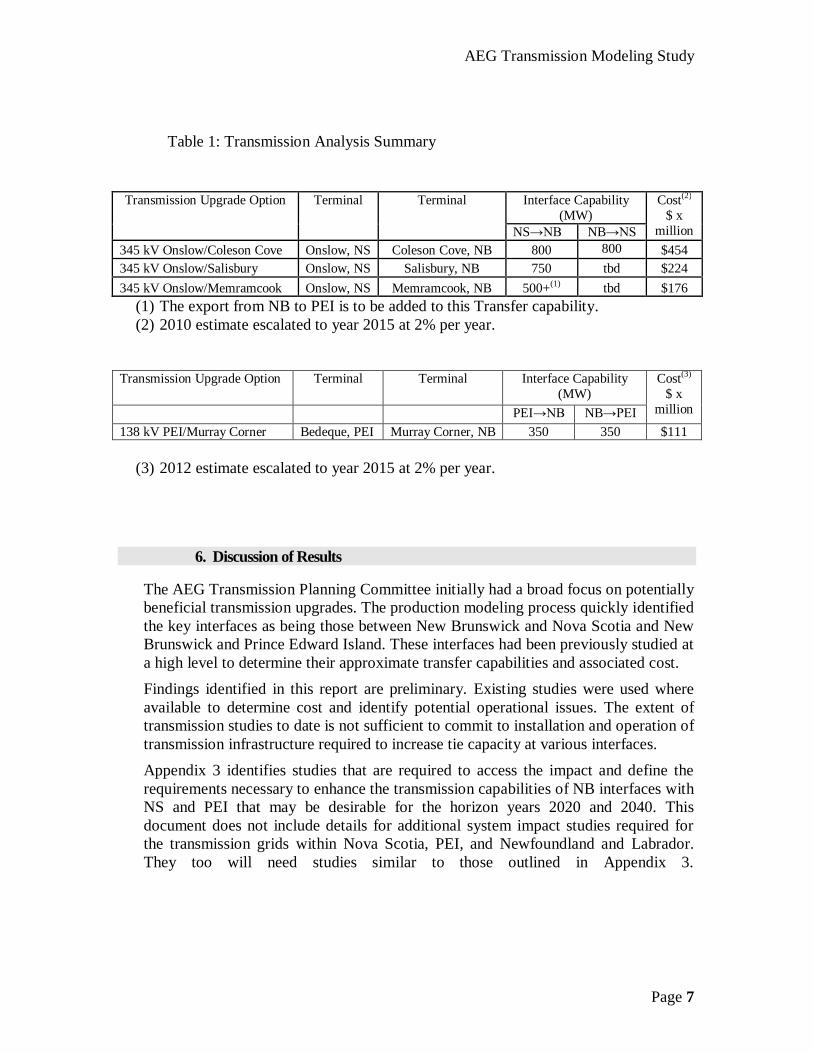
Table 1: Transmission Analysis Summary
(1) The export from NB to PEI is to be added to this Transfer capability. (2) 2010 estimate escalated to year 2015 at 2% per year.
Transmission Upgrade Option Terminal Terminal
Interface Capability (MW)
PEI→NB NB→PEI
Cost(3) $ x
million 138 kV PEI/Murray Corner Bedeque, PEI Murray Corner, NB 350 350 $111
(3) 2012 estimate escalated to year 2015 at 2% per year.
6. Discussion of Results
The AEG Transmission Planning Committee initially had a broad focus on potentially beneficial transmission upgrades. The production modeling process quickly identified the key interfaces as being those between New Brunswick and Nova Scotia and New Brunswick and Prince Edward Island. These interfaces had been previously studied at a high level to determine their approximate transfer capabilities and associated cost. Findings identified in this report are preliminary. Existing studies were used where available to determine cost and identify potential operational issues. The extent of transmission studies to date is not sufficient to commit to installation and operation of transmission infrastructure required to increase tie capacity at various interfaces. Appendix 3 identifies studies that are required to access the impact and define the requirements necessary to enhance the transmission capabilities of NB interfaces with NS and PEI that may be desirable for the horizon years 2020 and 2040. This document does not include details for additional system impact studies required for the transmission grids within Nova Scotia, PEI, and Newfoundland and Labrador. They too will need studies similar to those outlined in Appendix 3.
Interface Capability (MW)
Transmission Upgrade Option Terminal Terminal
NS→NB NB→NS
Cost(2) $ x
million 345 kV Onslow/Coleson Cove Onslow, NS Coleson Cove, NB 800 800 $454 345 kV Onslow/Salisbury Onslow, NS Salisbury, NB 750 tbd $224 345 kV Onslow/Memramcook Onslow, NS Memramcook, NB 500+(1) tbd $176
AEG Transmission Modeling Study
Appendix 1 - Page 1
AEG Transmission Modeling Study
Appendix 1
Table 1: Preliminary List of AEG Regional Transmission Upgrade Options # Transmission Upgrade Option Terminal (From) Terminal
(To)
1a 345 kV Onslow/Coleson Cove Onslow, NS Coleson Cove, NB 1b 345 kV Onslow/Salisbury Onslow, NS Salisbury, NB 1c 345 kV Onslow/Memramcook Onslow, NS Memramcook, NB 2a 138 kV PEI/Memramcook PEI Memramcook, NB 2b 138 kV PEI/Murray Corner PEI Murray Corner, NB 3 138 kV PEI/NS PEI NS 4 HVDC Bottom Brook/Lingan Bottom Brook,NL Near Lingan, NS 5 HVDC NL/Salisbury NL Salisbury, NB 6 Options 1a & 2a n/a n/a 7 Options 1a & 2a & 4 n/a n/a 8 345 kV Lepreau/Orrington Lepreau, NB Orrington, Maine 9 HVDC NB/HQ NB HQ
10 HVDC Lepreau/NE Lepreau, NB tbd 11 HVDC Lepreau/NE Lepreau, NB tbd 12 Options 7 & 8 n/a n/a 13 Options 7 & 9 n/a n/a 14 Options 7 & 8 & 9 n/a n/a 15 345 kV Digby/Lepreau Digby, NS Coleson Cove, NB 16 Upgrade NB & MPS Interface tbd tbd
AEG Transmission Modeling Study
Appendix 2 - Page 1
AEG Transmission Modeling Study
Appendix 2
Summary of Existing Firm and Non-Firm Transmission Capacity of New Brunswick Interfaces
With Nova Scotia and PEI
For AEG Resource Group Modelling
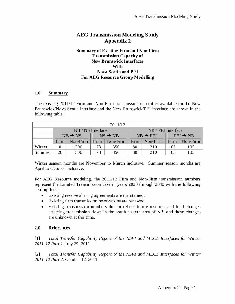
1.0 Summary The existing 2011/12 Firm and Non-Firm transmission capacities available on the New Brunswick/Nova Scotia interface and the New Brunswick/PEI interface are shown in the following table.
2011/12 NB / NS Interface NB / PEI Interface NB NS NS NB NB PEI PEI NB
Firm Non-Firm Firm Non-Firm Firm Non-Firm Firm Non-Firm Winter 0 300 178 350 80 210 105 105 Summer 20 300 178 350 80 210 105 105 Winter season months are November to March inclusive. Summer season months are April to October inclusive. For AEG Resource modeling, the 2011/12 Firm and Non-Firm transmission numbers represent the Limited Transmission case in years 2020 through 2040 with the following assumptions:
Existing reserve sharing agreements are maintained. Existing firm transmission reservations are renewed. Existing transmission numbers do not reflect future resource and load changes
affecting transmission flows in the south eastern area of NB, and these changes are unknown at this time.
2.0 References [1] Total Transfer Capability Report of the NSPI and MECL Interfaces for Winter 2011-12 Part 1. July 29, 2011 [2] Total Transfer Capability Report of the NSPI and MECL Interfaces for Winter 2011-12 Part 2. October 12, 2011
AEG Transmission Modeling Study
Page 2
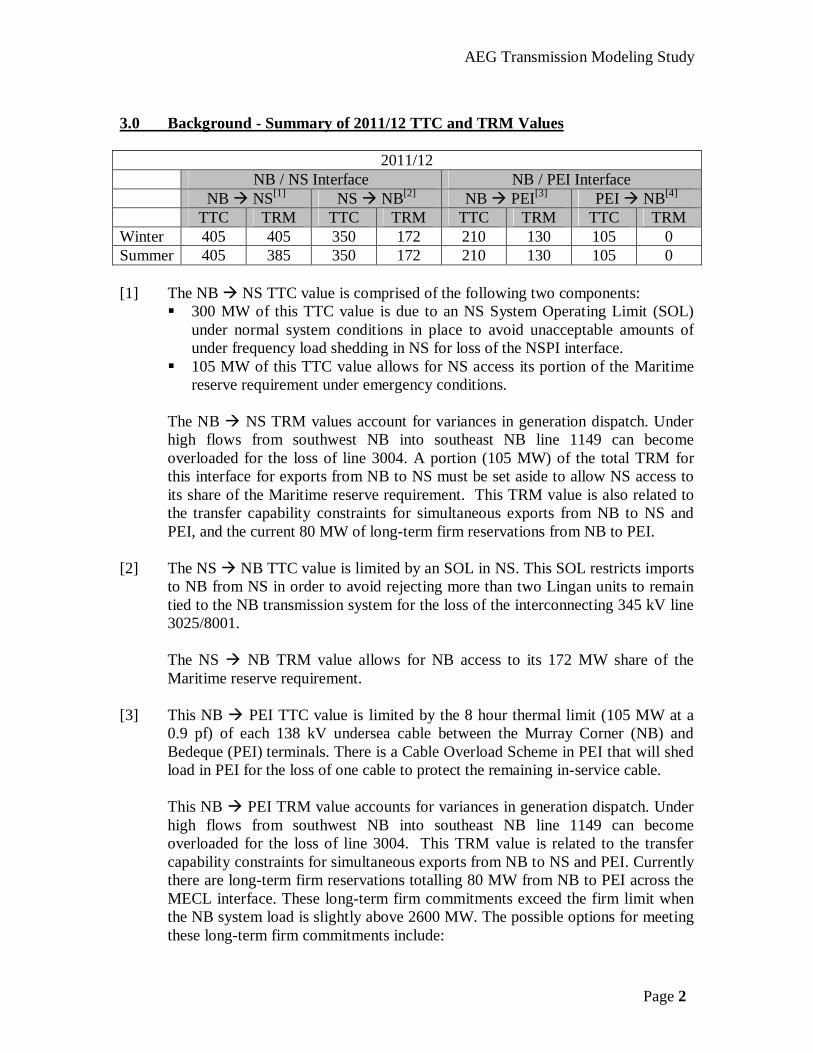
3.0 Background - Summary of 2011/12 TTC and TRM Values
2011/12 NB / NS Interface NB / PEI Interface NB NS[1] NS NB[2] NB PEI[3] PEI NB[4]
TTC TRM TTC TRM TTC TRM TTC TRM Winter 405 405 350 172 210 130 105 0 Summer 405 385 350 172 210 130 105 0 [1] The NB NS TTC value is comprised of the following two components:
300 MW of this TTC value is due to an NS System Operating Limit (SOL) under normal system conditions in place to avoid unacceptable amounts of under frequency load shedding in NS for loss of the NSPI interface.
105 MW of this TTC value allows for NS access its portion of the Maritime reserve requirement under emergency conditions.
The NB NS TRM values account for variances in generation dispatch. Under high flows from southwest NB into southeast NB line 1149 can become overloaded for the loss of line 3004. A portion (105 MW) of the total TRM for this interface for exports from NB to NS must be set aside to allow NS access to its share of the Maritime reserve requirement. This TRM value is also related to the transfer capability constraints for simultaneous exports from NB to NS and PEI, and the current 80 MW of long-term firm reservations from NB to PEI.
[2] The NS NB TTC value is limited by an SOL in NS. This SOL restricts imports to NB from NS in order to avoid rejecting more than two Lingan units to remain tied to the NB transmission system for the loss of the interconnecting 345 kV line 3025/8001.
The NS NB TRM value allows for NB access to its 172 MW share of the Maritime reserve requirement.
[3] This NB PEI TTC value is limited by the 8 hour thermal limit (105 MW at a 0.9 pf) of each 138 kV undersea cable between the Murray Corner (NB) and Bedeque (PEI) terminals. There is a Cable Overload Scheme in PEI that will shed load in PEI for the loss of one cable to protect the remaining in-service cable.
This NB PEI TRM value accounts for variances in generation dispatch. Under high flows from southwest NB into southeast NB line 1149 can become overloaded for the loss of line 3004. This TRM value is related to the transfer capability constraints for simultaneous exports from NB to NS and PEI. Currently there are long-term firm reservations totalling 80 MW from NB to PEI across the MECL interface. These long-term firm commitments exceed the firm limit when the NB system load is slightly above 2600 MW. The possible options for meeting these long-term firm commitments include:
AEG Transmission Modeling Study
Page 3
The appropriate dispatch of generation. Implementing a temporary operational mitigation measure to monitor loading
on line 1149 and take operator action as needed. [4] This PEI NB TTC value is limited by the eight hour thermal limit (117 MVA)
of one undersea 138 kV cable between NB and PEI for the loss of the other 138 kV undersea cable. A power factor of 0.90 has been factored into the TTC limit.
There is no TRM required.
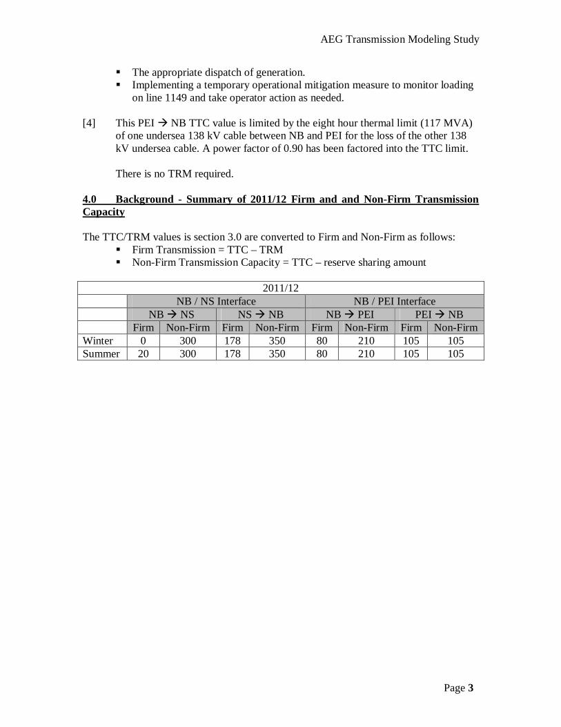
4.0 Background - Summary of 2011/12 Firm and and Non-Firm Transmission Capacity The TTC/TRM values is section 3.0 are converted to Firm and Non-Firm as follows:
Firm Transmission = TTC – TRM Non-Firm Transmission Capacity = TTC – reserve sharing amount
2011/12
NB / NS Interface NB / PEI Interface NB NS NS NB NB PEI PEI NB
Firm Non-Firm Firm Non-Firm Firm Non-Firm Firm Non-Firm Winter 0 300 178 350 80 210 105 105 Summer 20 300 178 350 80 210 105 105
AEG Transmission Modeling Study
Appendix 3 - Page 1
AEG Transmission Modeling Study
Appendix 3
Scope of Transmission Studies to Accommodate the Proposed AEG Transfer Levels Via
NB Interfaces with its Atlantic Neighbours 2020 to 2040
January 30, 2012
Power System Engineering
New Brunswick System Operator 510-C Brookside Drive
Fredericton, NB Canada E3A 8V2
AEG Transmission Modeling Study
Appendix 4 - Page 2
Scope of Transmission Studies to Accommodate the Proposed AEG
Power Transfer Levels Via NB interfaces with its Atlantic Neighbours 2020 to 2040
1. Background Information
The Atlantic Energy Gateway (AEG) initiative is an opportunity to promote and facilitate the development of clean and renewable energy sources in Atlantic Canada. The initiative will complement all current and future energy plans and resources being undertaken in the region in the timeframe between 2020 to 2040.
The AEG Initiative involves work by the four Atlantic Canada energy
departments, their provincial utilities and ACOA and Natural Resources Canada. The work includes planning for generation, transmission, and system operation, as well as electricity markets, supply chain development, research and development and regulatory improvements.
Because of its geographic location New Brunswick is impacted by changes to
import, export and wheeling of electrical power directly to and from Nova Scotia, Prince Edward Island, Quebec and New England, and indirectly to and from Newfoundland and Labrador.
2. Objectives of this Document:
1. Give a brief summary of the existing Total Transmission Capabilities (TTC) between NB and its neighbouring systems with focus on NB interface capabilities with NS and PEI.
2. Give a scope of the transmission studies required to assess the impact and define
the requirements necessary to enhance the transmission capabilities of NB interfaces with NS and PEI, in light of the preliminary findings of the AEG Resource Modeling and Transmission groups for the horizon years 2020 and 2040.
3. Give an estimate of the man-weeks required to complete the studies.
4. This document does not include details for additional system impact studies
required for the transmission grids in Nova Scotia, PEI, and Newfoundland and Labrador.
.
AEG Transmission Modeling Study
Appendix 4 - Page 3
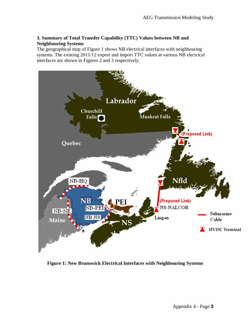
3. Summary of Total Transfer Capability (TTC) Values between NB and Neighbouring Systems The geographical map of Figure 1 shows NB electrical interfaces with neighbouring systems. The existing 2011/12 export and import TTC values at various NB electrical interfaces are shown in Figures 2 and 3 respectively.
Figure 1: New Brunswick Electrical Interfaces with Neighbouring Systems
AEG Transmission Modeling Study
Appendix 4 - Page 4
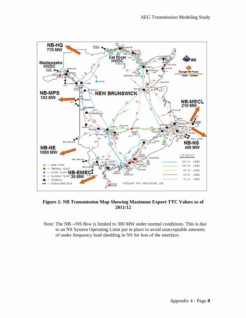
Figure 2: NB Transmission Map Showing Maximum Export TTC Values as of 2011/12
Note: The NB→NS flow is limited to 300 MW under normal conditions. This is due to an NS System Operating Limit put in place to avoid unacceptable amounts of under frequency load shedding in NS for loss of the interface.
AEG Transmission Modeling Study
Appendix 4 - Page 5
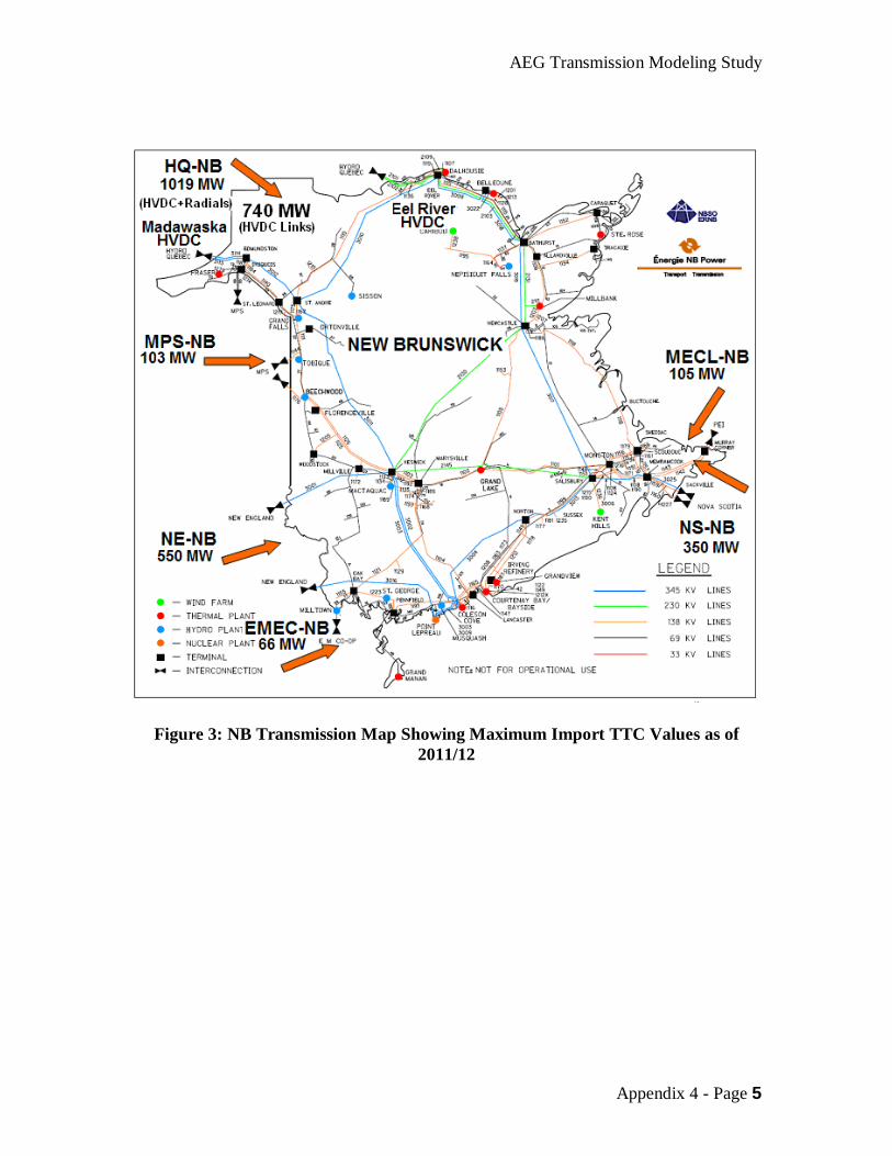
Figure 3: NB Transmission Map Showing Maximum Import TTC Values as of 2011/12
AEG Transmission Modeling Study
Appendix 4 - Page 6
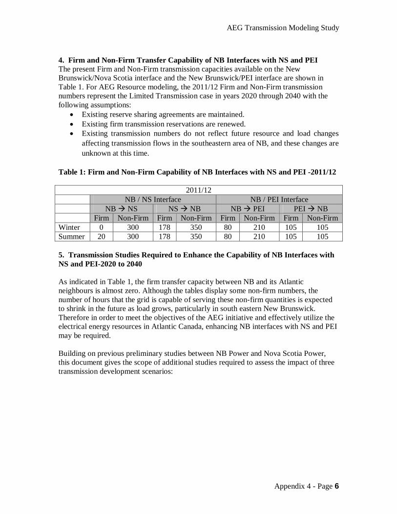
4. Firm and Non-Firm Transfer Capability of NB Interfaces with NS and PEI The present Firm and Non-Firm transmission capacities available on the New Brunswick/Nova Scotia interface and the New Brunswick/PEI interface are shown in Table 1. For AEG Resource modeling, the 2011/12 Firm and Non-Firm transmission numbers represent the Limited Transmission case in years 2020 through 2040 with the following assumptions:
Existing reserve sharing agreements are maintained. Existing firm transmission reservations are renewed. Existing transmission numbers do not reflect future resource and load changes
affecting transmission flows in the southeastern area of NB, and these changes are unknown at this time.
Table 1: Firm and Non-Firm Capability of NB Interfaces with NS and PEI -2011/12
2011/12 NB / NS Interface NB / PEI Interface NB NS NS NB NB PEI PEI NB
Firm Non-Firm Firm Non-Firm Firm Non-Firm Firm Non-Firm Winter 0 300 178 350 80 210 105 105 Summer 20 300 178 350 80 210 105 105 5. Transmission Studies Required to Enhance the Capability of NB Interfaces with NS and PEI-2020 to 2040 As indicated in Table 1, the firm transfer capacity between NB and its Atlantic neighbours is almost zero. Although the tables display some non-firm numbers, the number of hours that the grid is capable of serving these non-firm quantities is expected to shrink in the future as load grows, particularly in south eastern New Brunswick. Therefore in order to meet the objectives of the AEG initiative and effectively utilize the electrical energy resources in Atlantic Canada, enhancing NB interfaces with NS and PEI may be required. Building on previous preliminary studies between NB Power and Nova Scotia Power, this document gives the scope of additional studies required to assess the impact of three transmission development scenarios:
AEG Transmission Modeling Study
Appendix 4 - Page 7
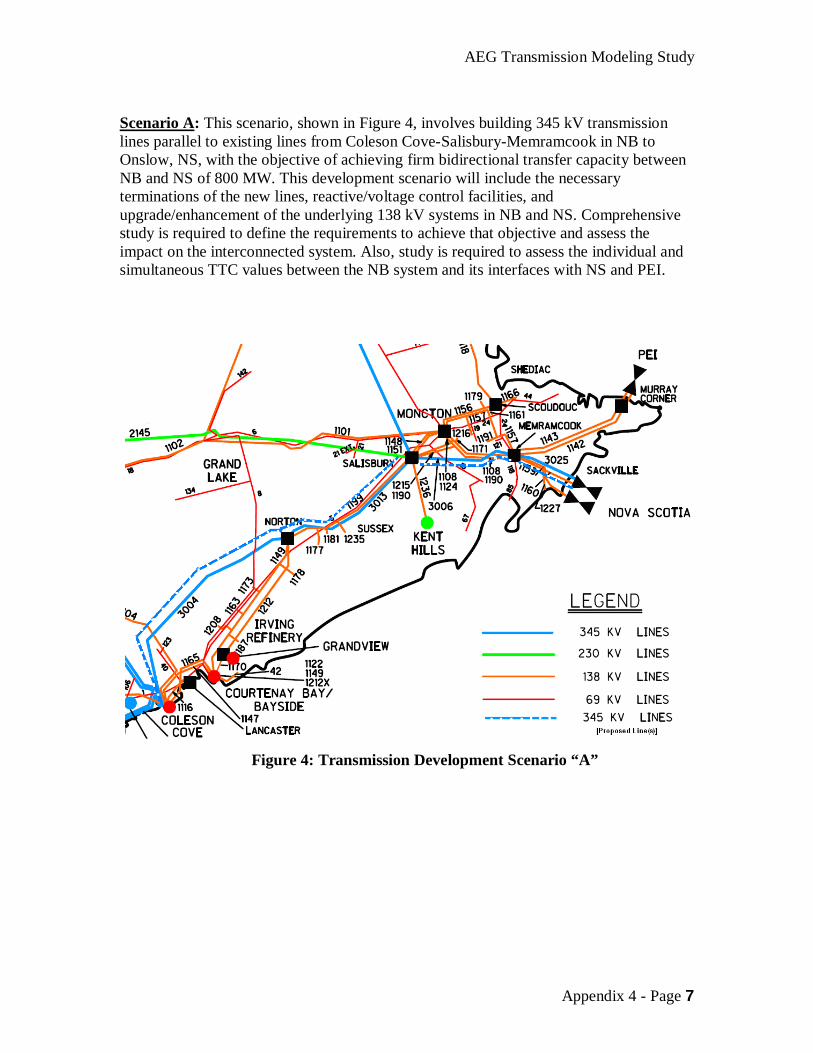
Scenario A: This scenario, shown in Figure 4, involves building 345 kV transmission lines parallel to existing lines from Coleson Cove-Salisbury-Memramcook in NB to Onslow, NS, with the objective of achieving firm bidirectional transfer capacity between NB and NS of 800 MW. This development scenario will include the necessary terminations of the new lines, reactive/voltage control facilities, and upgrade/enhancement of the underlying 138 kV systems in NB and NS. Comprehensive study is required to define the requirements to achieve that objective and assess the impact on the interconnected system. Also, study is required to assess the individual and simultaneous TTC values between the NB system and its interfaces with NS and PEI.
Figure 4: Transmission Development Scenario “A”
AEG Transmission Modeling Study
Appendix 4 - Page 8
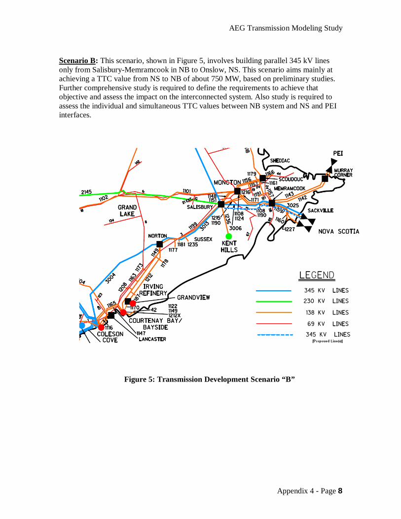
Scenario B: This scenario, shown in Figure 5, involves building parallel 345 kV lines only from Salisbury-Memramcook in NB to Onslow, NS. This scenario aims mainly at achieving a TTC value from NS to NB of about 750 MW, based on preliminary studies. Further comprehensive study is required to define the requirements to achieve that objective and assess the impact on the interconnected system. Also study is required to assess the individual and simultaneous TTC values between NB system and NS and PEI interfaces.
Figure 5: Transmission Development Scenario “B”
AEG Transmission Modeling Study
Appendix 4 - Page 9
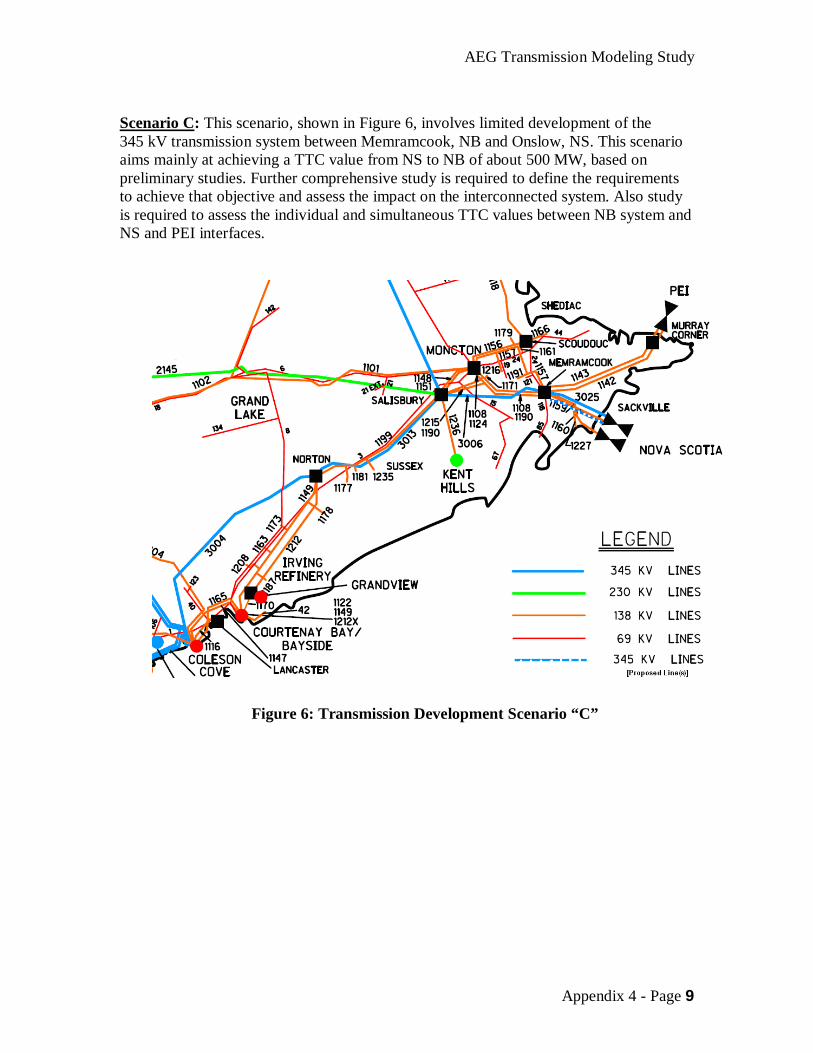
Scenario C: This scenario, shown in Figure 6, involves limited development of the 345 kV transmission system between Memramcook, NB and Onslow, NS. This scenario aims mainly at achieving a TTC value from NS to NB of about 500 MW, based on preliminary studies. Further comprehensive study is required to define the requirements to achieve that objective and assess the impact on the interconnected system. Also study is required to assess the individual and simultaneous TTC values between NB system and NS and PEI interfaces.
Figure 6: Transmission Development Scenario “C”
AEG Transmission Modeling Study
Appendix 4 - Page 10
6. Study Scope for Transmission Development Scenario ‘A” for 2020/2021: Basic Assumptions:
Study year 2020. No under voltage load shedding, no curtailment of firm load or firm transactions
for design (normal criteria) contingencies as per NPCC and NERC criteria and standards.
Size of largest acceptable loss of load in the Maritimes is 250 MW. Transmission development under the MPRP in Maine, USA is complete. Size of the largest acceptable loss of source in the Maritimes is 740 MW
(Equivalent to simultaneous import from both Madawaska and Eel River). A third cable between PEI and NB is installed. Development of Muskrat Falls project. The HVDC interconnection between NFLD and NS has been developed. Any other transmission or generation projects in Atlantic Canada and Maine,
USA foreseen by 2020. Base Case Development:
Load Levels Based on forecasted load in NB and neighbouring systems for year 2020:
o Winter Peak o Summer Peak Load o Summer Light Load
Generation dispatch in NB and the Maritimes in general: Include all committed wind generation or any other potential projects by 2020 as presented in the AEG resource modeling group report.
A special Winter Peak base case without any wind generation in the Maritimes will be developed.
Network configuration and assumptions for new transmission facilities will be modeled as in the most recent NPCC Overall Transmission Review. The base cases will be modified to incorporate any additional transmission reinforcements in NB and NS systems, which will be identified in the course of this SIS, for the purpose of accommodation of the TSRs from HQ to NS.
Import/Export conditions over NB interconnections with, Quebec and New England will be modeled at their Total Transfer Capabilities.
Approach for Developing the Base Cases for Transmission:
Start from Base Cases of the most recent NPCC Overall Transmission Review. Update load, dispatch and network for 2020/2021 as per most recent load forecast. Incorporate NB, NS and PEI initial modeling assumptions for their respective
systems. o NB/NS interface upgrades o HVDC bus location to connect Nova Scotia with NALCOR.
AEG Transmission Modeling Study
Appendix 4 - Page 11
o Model other potential transmission assumptions for each of the three transmission development scenarios A, B and C (e.g. 345 kV reinforcement between Coleson Cove, Salisbury, Memramcook and Onslow).
o Model any additional reinforcements required for the underlying 138 kV system and voltage/reactive controls.
o Model equivalent generators to account for potential new sources in the future as documented in by the AEG resource modeling group.
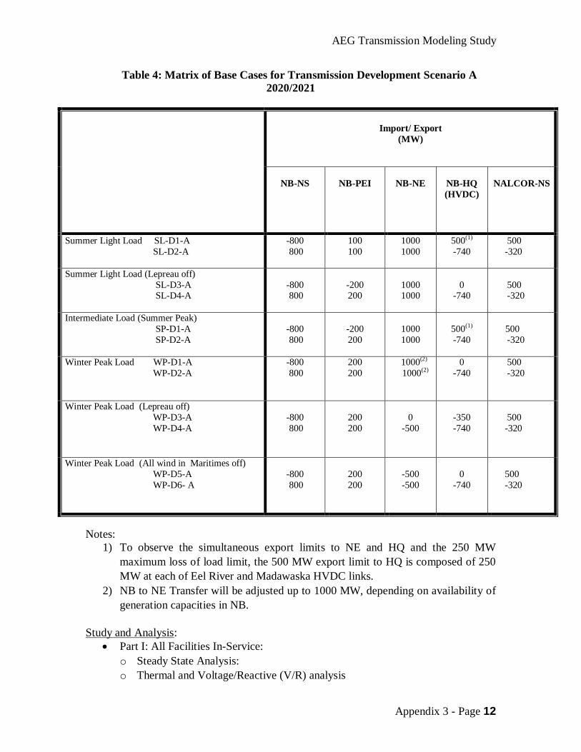
The tentative matrix of Base Cases for the study year 2020/2021, assuming the transmission scenario “A”, is shown in Table 4.
AEG Transmission Modeling Study
Appendix 3 - Page 12
Table 4: Matrix of Base Cases for Transmission Development Scenario A 2020/2021
Import/ Export (MW)
NB-NS
NB-PEI
NB-NE
NB-HQ (HVDC)
NALCOR-NS
Summer Light Load SL-D1-A SL-D2-A
-800 800
100 100
1000 1000
500(1) -740
500 -320
Summer Light Load (Lepreau off) SL-D3-A SL-D4-A
-800 800
-200 200
1000 1000
0
-740
500 -320
Intermediate Load (Summer Peak) SP-D1-A SP-D2-A
-800 800
-200 200
1000 1000
500(1) -740
500 -320
Winter Peak Load WP-D1-A WP-D2-A
-800 800
200 200
1000(2)
1000(2)
0 -740
500 -320
Winter Peak Load (Lepreau off) WP-D3-A WP-D4-A
-800 800
200 200
0
-500
-350 -740
500 -320
Winter Peak Load (All wind in Maritimes off) WP-D5-A WP-D6- A
-800 800
200 200
-500 -500
0
-740
500 -320
Notes:
1) To observe the simultaneous export limits to NE and HQ and the 250 MW maximum loss of load limit, the 500 MW export limit to HQ is composed of 250 MW at each of Eel River and Madawaska HVDC links.
2) NB to NE Transfer will be adjusted up to 1000 MW, depending on availability of generation capacities in NB.
Study and Analysis:
Part I: All Facilities In-Service: o Steady State Analysis: o Thermal and Voltage/Reactive (V/R) analysis
AEG Transmission Modeling Study
Appendix 4 - Page 13
o Single Contingency Load Flow Analysis o Identify any additional facilities required to support the transfers listed in the
matrix of base cases. Modify the base case as necessary. o Normal Criteria Transient Stability and Post Contingency Analysis o Extreme Contingency Analysis. To test if there is an adverse system impact
that may require mitigation measures. o Review of Special Protection Systems (SPSs) o Short Circuit Analysis. To test if there is a need to upgrade the protection or
switching switchgear. o Conclusions and Recommendations for Part I
Part II: Under Single Contingency Outage (n-1) Conditions o List of Facilities out-of-service. o For each out-of-service facility reconstruct a new base case, taking into consideration the 30 minute dispatch including adjusting the transfers between NB and its neighbouring systems. o Reconstruct base case import/export matrix. o Steady State Analysis. o Thermal and V/R analysis. o Single Contingency Load Flow Analysis o Normal Criteria Transient Stability and Post Contingency Analysis o Extreme Contingency Analysis o Review of Special Protection Systems (SPSs) o Short Circuit Analysis o Conclusions and Recommendations for Part II
Study Scope for Transmission Development Scenario ‘A” for 2040/2041: Modify the matrix of base cases as per the input from the AEG Resource Group. Repeat the analysis for year 2040/2041 following the same procedure as given in Section 6 for year 2020/2021. Study Scopes for Transmission Development Scenarios ‘B” and “C” are similar to “A”, but require development of new matrices of base cases, based on input from the AEG Resource Group.
AEG Transmission Modeling Study
Appendix 4 - Page 14
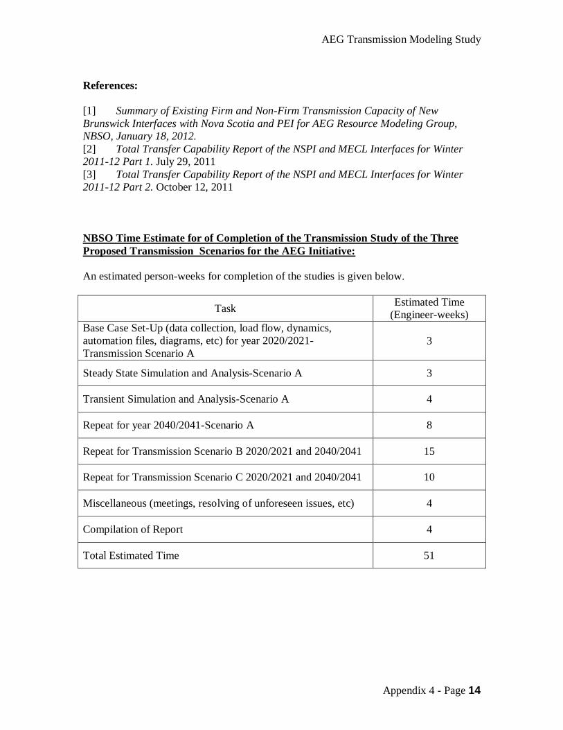
References: [1] Summary of Existing Firm and Non-Firm Transmission Capacity of New Brunswick Interfaces with Nova Scotia and PEI for AEG Resource Modeling Group, NBSO, January 18, 2012. [2] Total Transfer Capability Report of the NSPI and MECL Interfaces for Winter 2011-12 Part 1. July 29, 2011 [3] Total Transfer Capability Report of the NSPI and MECL Interfaces for Winter 2011-12 Part 2. October 12, 2011 NBSO Time Estimate for of Completion of the Transmission Study of the Three Proposed Transmission Scenarios for the AEG Initiative: An estimated person-weeks for completion of the studies is given below.
Task Estimated Time (Engineer-weeks)
Base Case Set-Up (data collection, load flow, dynamics, automation files, diagrams, etc) for year 2020/2021- Transmission Scenario A
3
Steady State Simulation and Analysis-Scenario A 3
Transient Simulation and Analysis-Scenario A 4
Repeat for year 2040/2041-Scenario A 8
Repeat for Transmission Scenario B 2020/2021 and 2040/2041 15
Repeat for Transmission Scenario C 2020/2021 and 2040/2041 10
Miscellaneous (meetings, resolving of unforeseen issues, etc) 4
Compilation of Report 4
Total Estimated Time 51
AEG Transmission Modeling Study
Appendix 4 - Page 1
AEG Transmission Modeling Study Appendix 4
Labrador – Island Link and Maritime Link Description
Introduction
Phase One of the Lower Churchill Project includes development of the Muskrat Falls generating facility on the lower Churchill river in Labrador, construction of high voltage ac transmission between Churchill Falls and Muskrat Falls, construction of an HVdc transmission system between Labrador and the Island of Newfoundland, high voltage ac transmission upgrades on the Island and construction of an HVdc transmission system between Newfoundland and Nova Scotia.
Muskrat Falls Generating Station
The Muskrat Falls Generating Station will consist of four 206 MW hydroelectric generator sets for a rated plant capacity of 824 MW. The electric generators will have a 0.90 power factor to provide the necessary reactive power supply to the HVdc converter station located adjacent to the plant. Kaplan turbines will be utilized as the prime mover.
Labrador Transmission Additions
The Muskrat Falls generator step-up transformers will increase the voltage from the rated terminal voltage of the machine to 315 kV. Two single circuit, 250 km long, 315 kV transmission lines will connect the Muskrat Falls switchyard to the switchyard at Churchill Falls. At Churchill Falls an extension to the 735 kV switchyard will include 735/315 kV autotransformers and the 315 kV transmission line terminations.
Labrador – Island Link (LIL)
The Labrador – Island HVdc Transmission System, or LIL, will be a ±350 kV bipole with a rating of 900 MW (450 MW per pole). The system will utilize line commutated converter technology. The transmission system includes 380 km of overhead HVdc transmission line in Labrador, a 30 km submarine cable crossing of the Strait of Belle Isle and 688 km of overhead HVdc transmission line on the Island of Newfoundland. The overhead transmission system will include optical fibre in the overhead ground wire for high speed communication between converter stations The converter station in Labrador will be located adjacent to the Muskrat Falls Generating Station. The converter station on the Island of Newfoundland will be located on the Avalon Peninsula near the major load center at a location called Soldiers Pond. Soldiers Pond has been selected as the location of the converter station given that:
AEG Transmission Modeling Study
Appendix 4 - Page 2
it is located between the Holyrood Thermal Generating Station (which will cease production with the construction of the LIL) and the load center on the northeastern Avalon Peninsula; and
all major 230 kV transmission lines in the region converge near this location, thereby reducing ac transmission line upgrades.
The LIL will have a nominal rating of 900 MW in bi-pole mode. In mono-polar mode each pole is capable of operating at 900 MW for ten minutes and 675 MW continuous. This arrangement prevents loss of load/load shedding on the Island of Newfoundland system for permanent loss of a pole. The 10 minute, 900 MW rating provides time for operators on the Island to start standby generation. The Soldiers Pond converter station will include three high inertia synchronous condensers for voltage support, reactive power control, equivalent short circuit ratio and frequency support for the wide operating range of the LIL. The system is designed to withstand the temporary loss of the bi-pole (i.e. pole-to-pole faults). The Strait of Belle Isle cable crossing will include three cables (one energized spare) and switching arrangements at both cable transition compounds for redundancy.
System Upgrades Island of Newfoundland
Upgrades to the ac transmission system on the Island of Newfoundland include 230 kV circuit breaker replacements due to increase short circuit levels, conversion of units at Holyrood to synchronous condenser capability and thermal uprating of a number of 230 kV transmission lines.
Maritime Link (ML)
The Maritime Link will connect the 230 kV ac transmission system on the western portion of the Island of Newfoundland to Cape Breton in Nova Scotia. The system will be rated ±200 kV and 500 MW in bi-pole mode. Given the relatively weak connection points in both the Newfoundland and Nova Scotia systems, the voltage source converter technology will be employed. The HVdc transmission system will consist of 130 km of overhead HVdc transmission line from Bottom Brook in Newfoundland to the Cabot Strait, 180 km of submarine cable across the Cabot Strait and approximately 46 km of overhead HVdc in Cape Breton to the NSPI ac transmission system. To limit the impact of ML outages, an asymetrical bi-pole arrangement will be used for the VSC converters to permit mono-polar operation of ML. This, in turn, provides a mono-polar rating of 250 MW. The addition of a new 230 kV transmission line from Granite Canal to Bottom Brook on the Newfoundland transmission system permits transfer of up to 250 MW via the ML for single 230 kV transmission contingencies on the Island of Newfoundland.

AEG Transmission Modeling Study
Appendix 4 - Page 3
The ML will be bi-directional in design such that power and energy can be imported from the Maritimes to Newfoundland should there be a sustained forced bi-pole outage to the LIL.
Recommended