BUCKLING ANALYSIS OF AN IMPERFECTION-INSENSITIVE COMPOSITE CYLINDER
UNDER AXIAL COMPRESSION – EXPERIMENTAL TESTING AND SIMULATION
H.N.R. Wagnera, E. Petersenb, R.Khakimovac and C. Hühnea,b
aInstitute of Adaptronic and Functional Integration, Langer Kamp 6, 38106 Braunschweig, Germany [email protected] bInstitute for Composite Structures and Adaptive Systems, German Aerospace Center (DLR), Lilienthalplatz 7, 38108 Braunschweig, Germany [email protected] [email protected] cFraunhofer institute, Open Hybrid LabFactory e.V., Hermann-Münch-Straße 2, 38440 Wolfsburg, Germany [email protected]
Keywords: Ariane 6, Buckling, cylinder, imperfection, knockdown factor, plastic buckling,
robust design, Southwell-method
Abstract
Thin-walled shells like cylinders are primary structures in launch-vehicle systems. When subjected to axial loading these shells are prone to buckling. The corresponding critical load heavily depends on deviations from the ideal shell shape. In general, these deviations are defined as geometric imperfections and although imperfections exhibit comparatively low amplitudes, they can significantly reduce the critical load. Considering the influence of geometric imperfections adequately into the design process of thin-walled shells poses major challenges for structural design. An alternative to robust design of thin-walled shell by accurate consideration of geometric imperfections is the development of a robust or imperfection-insensitive shell architecture. In this article a special hybrid cylinder is presented and analyzed. The composite shell design is based on an interstage structure of the Ariane 6 by MT Aerospace and has special CFRP belts which are intended to reduce the imperfection sensitivity of the shell. The shell was tested at the German Aerospace Center in Braunschweig and the corresponding results are presented and described. The hybrid cylinder was analyzed with the Southwell-method and geometrically nonlinear finite element analyzes. The results show that the Southwell-method delivers conservative buckling load estimations and that the CFRP belts reduce the imperfection sensitivity significantly.
Abbreviations and glossary
Exp. Experiment
F Axial force
GNA Geometrically nonlinear analysis
KDF Knockdown factor
L Free length of a cylinder
N Buckling load
R Cylinder Radius
t Wall thickness of a cylinder
1 Introduction Thin-walled shell structures, like cylinder are important structural elements for launch-vehicle
systems. These shells are subjected to axial compression due to weight of the upper structural
elements and propulsive loads during launch. Within this article, the maximum load carrying
capability of thin-walled cylindrical shells under axial compression is defined as the buckling
load.
Launch-vehicle primary structures are increasingly being built from fiber-reinforced composite
materials [1]. These materials can have special advantages when compared to metals like high
specific strength and stiffness as well as good environmental and fatigue resistance [2], [3].
Besides monolithic composite shell structures, sandwich composite structures which consist of
a lightweight core and high strength and stiffness facesheets are also used as launch-vehicle
primary structures [4].
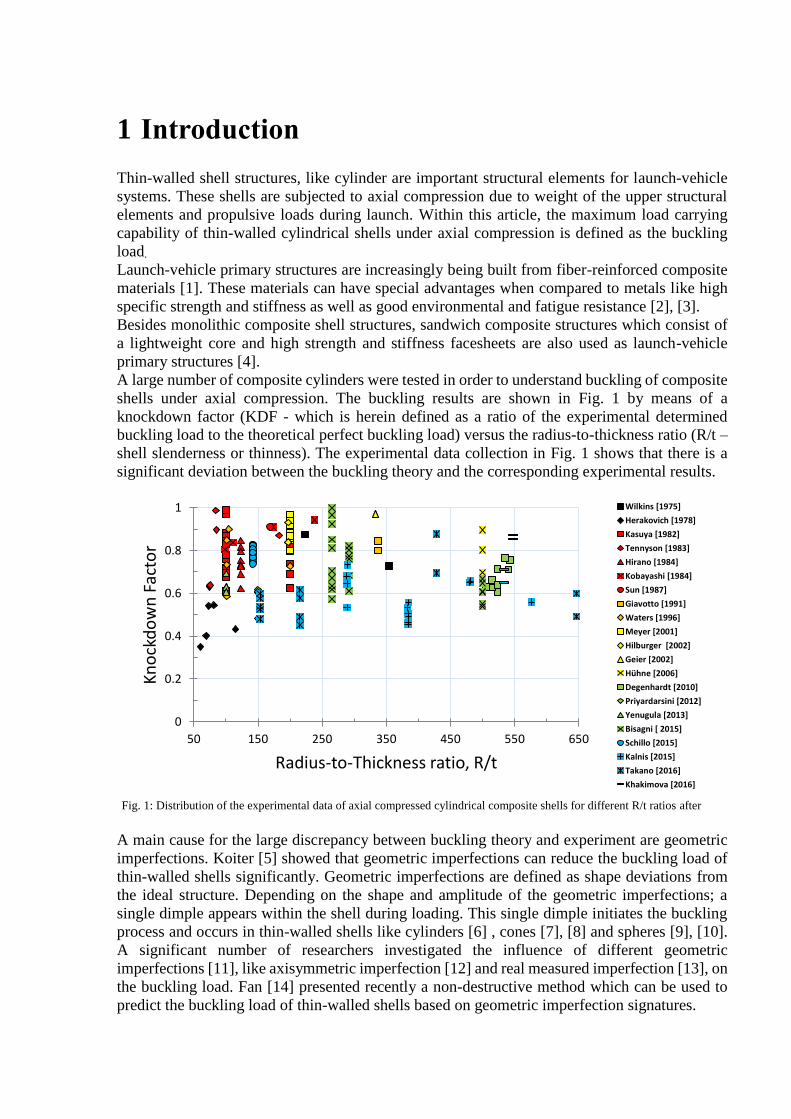
A large number of composite cylinders were tested in order to understand buckling of composite
shells under axial compression. The buckling results are shown in Fig. 1 by means of a
knockdown factor (KDF - which is herein defined as a ratio of the experimental determined
buckling load to the theoretical perfect buckling load) versus the radius-to-thickness ratio (R/t –
shell slenderness or thinness). The experimental data collection in Fig. 1 shows that there is a
significant deviation between the buckling theory and the corresponding experimental results.
Fig. 1: Distribution of the experimental data of axial compressed cylindrical composite shells for different R/t ratios after
A main cause for the large discrepancy between buckling theory and experiment are geometric
imperfections. Koiter [5] showed that geometric imperfections can reduce the buckling load of
thin-walled shells significantly. Geometric imperfections are defined as shape deviations from
the ideal structure. Depending on the shape and amplitude of the geometric imperfections; a
single dimple appears within the shell during loading. This single dimple initiates the buckling
process and occurs in thin-walled shells like cylinders [6] , cones [7], [8] and spheres [9], [10].
A significant number of researchers investigated the influence of different geometric
imperfections [11], like axisymmetric imperfection [12] and real measured imperfection [13], on
the buckling load. Fan [14] presented recently a non-destructive method which can be used to
predict the buckling load of thin-walled shells based on geometric imperfection signatures.
0
0.2
0.4
0.6
0.8
1
50 150 250 350 450 550 650
Kn
ock
do
wn
Fac
tor
Radius-to-Thickness ratio, R/t
Wilkins [1975]
Herakovich [1978]
Kasuya [1982]
Tennyson [1983]
Hirano [1984]
Kobayashi [1984]
Sun [1987]
Giavotto [1991]
Waters [1996]
Meyer [2001]
Hilburger [2002]
Geier [2002]
Hühne [2006]
Degenhardt [2010]
Priyardarsini [2012]
Yenugula [2013]
Bisagni [ 2015]
Schillo [2015]
Kalnis [2015]
Takano [2016]
Khakimova [2016]
However, the buckling load of thin-walled shells is not only reduced by traditional geometric
imperfections. But also by non-traditional imperfections like loading imperfections [15] or
delamination imperfections as recently shown by Wang et al. [16]. Loading imperfections are
defined as the deviation from the perfect homogenous load introduction of a shell [17]. There
are several known different loading imperfections like local concentrated loading imperfections
[18], [19] and uniform bending of the shell edge [20]. The buckling load reduces significantly if
loading imperfections occur which was shown in [21]. Therefore, they have to be considered in
the design process as well.
New design criteria for full-scale [22], [23] and sub-scale stiffened metal [24], [25] and sandwich
composite shells [4], [26], [27] are currently being developed by NASA in the Shell Buckling
Knockdown Factor Project (SBKF, references [28] and [29]). A detailed summary regarding the
SBKF project is given in [30] and [31].
A similar project started 2012 in Europe, the DESICOS project [32] (new robust DESign
guideline for Imperfection sensitive COmposite launcher Structures) to develop and validate
new deterministic [33], probabilistic [34] as well as experimental [35], [36] design approaches
for composite shells [37], [38], [39], [40]. A comprehensive overview regarding this project is
for example given in [2].
Recently, comprehensive imperfection sensitivity studies for cylindrical [41] and conical [42],
[43] composite shells were published which indicate that the current NASA recommendations
for composite shells may be very conservative for modern launch-vehicle structures.
Consequently, it was suggested to investigate the buckling response of composite shells through
buckling tests and analytical predictions.
An alternative to robust design of thin-walled shell by accurate consideration of geometric
imperfections is the development of a robust or imperfection-insensitive shell architecture. A
comprehensive overview regarding imperfection-insensitive shells is given by White and
Weaver in [44]. One approach to derive an imperfection insensitive shell structures is based on
the optimization of the laminate stacking sequence of a composite cylinder for maximum
buckling load and minimum imperfection sensitivity as for example shown by Wagner et al. [45]
or Hühne et al. [46]. Furthermore, there are concepts based on variable stiffness cylinders by
Labans et al. [47] or wavy cylinders by Ning et al. [48] and Yadav et al. [49].
In this article buckling test results for an imperfection-insensitive composite shell with a unique
architecture are presented. The composite shell has special carbon fiber reinforced polymer
(CFRP) belts which are intended to reduce the imperfection sensitivity of the shell by prohibiting
the formation of large (in amplitude and shape) dimple imperfection.
This paper is structured as follows: in the first part the high-performance cylinder is presented
along with a description of the test setup and the testing procedure. Afterwards numerical
analysis with respect to the CFRP belts and their imperfection sensitivity are shown. The paper
ends with a summary of all main results obtained within this article.
2 Test article description and testing
2.1 Test article
The test specimen considered in this article is an aluminum stringer stiffened composite cylinder
which was manufactured by TUM [50] and is denominated as Z39. The shells design is derived
from an interstage structure for the Ariane 6 and the manufacturing of this shell is described in
[50].
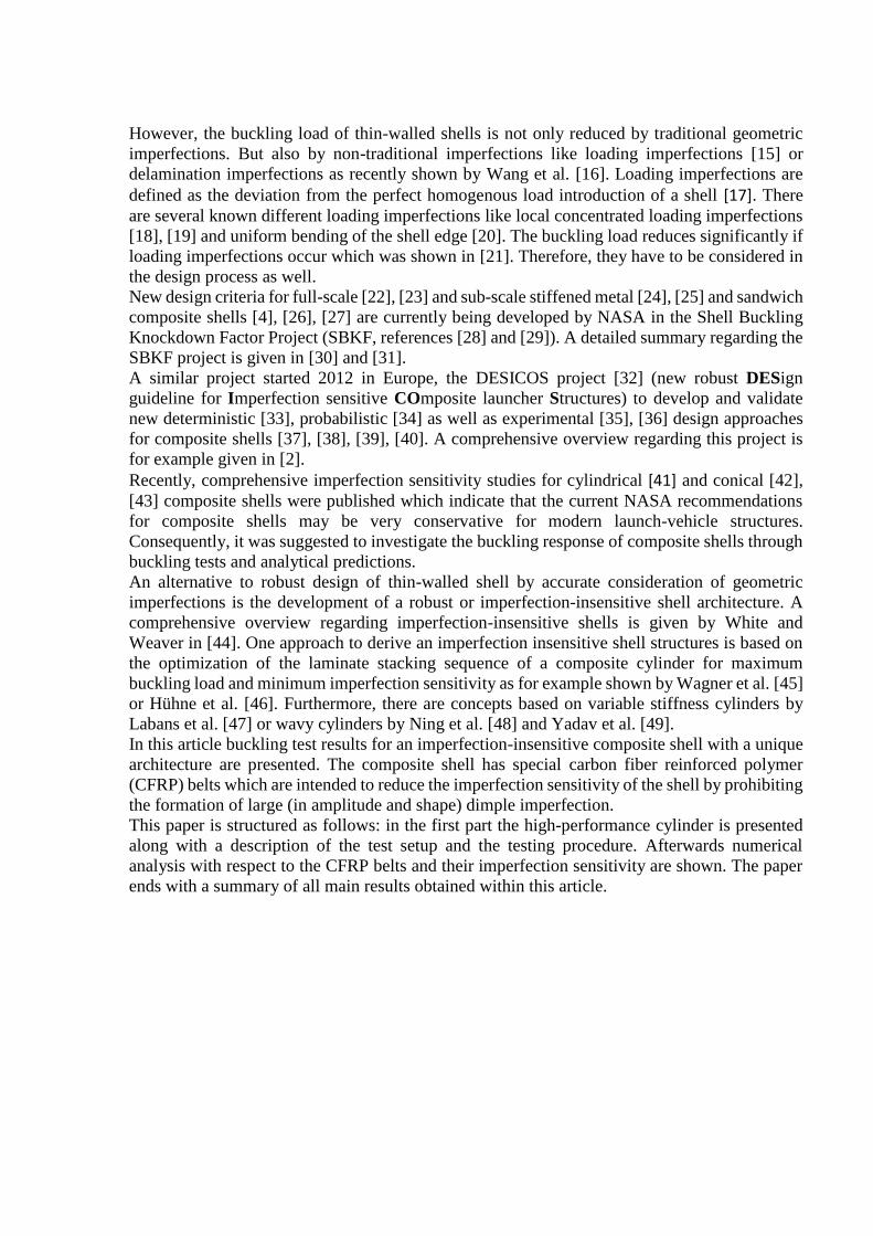
The shell has a length L = 1200 mm and a radius R = 400 mm. The inner surface of Z39 is
stiffened with 18 aluminum stringers as shown in Fig. 2 (right). The flange of the stringers has a
length of 25 mm, the thickness equals to 1.5 mm and the stringer height (stringer & flange)
equals to 13.5 mm.
In addition, there are three CFRP belts which divide the long shell into 4 short shells. The ply
layup of the inner composite cylinder surface consists of a quasi-isotropic stacking and has a
total thickness of 1.04 mm.
Fig. 2: Test specimen Z39 (left) inner aluminum stringers with geometric parameters (right)
The upper and lower ends of the cylinder were additionally reinforced with graded CFRP padups
(90-degree layers which were additionally added to the cylinder surface by winding) in order to
assist the load introduction.
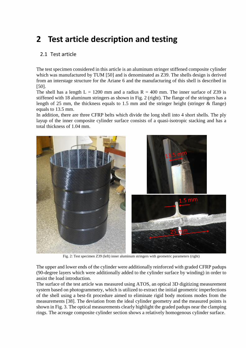
The surface of the test article was measured using ATOS, an optical 3D digitizing measurement
system based on photogrammetry, which is utilized to extract the initial geometric imperfections
of the shell using a best-fit procedure aimed to eliminate rigid body motions modes from the
measurements [38]. The deviation from the ideal cylinder geometry and the measured points is
shown in Fig. 3. The optical measurements clearly highlight the graded padups near the clamping
rings. The acreage composite cylinder section shows a relatively homogenous cylinder surface.
Fig. 4: Deviation of the cylinder surface versus the cylinder length (top) deviation of surface geometry from a best fit cylinder
(bottom)
The shell is set into metal plates with multiple grooves which have a depth of 50 mm for the
stringers, see Fig. 5 (top). That means the overall height of the structures was 1200 mm and the
free height of the test article excluding the metal rings was 1100 mm. This process has to be
performed in order to ensure the circular cross section of the structure and an even distribution
of the axial load. Then, after the resin is cured (see Fig. 6 – bottom), the second end is potted.
-1,5
1
3,5
6
8,5
0 200 400 600 800 1000 1200Dev
iati
on
fro
m c
ylin
der
su
rfac
e [m
m]
Cylinder Length [mm]
CFRP belts
graded padups
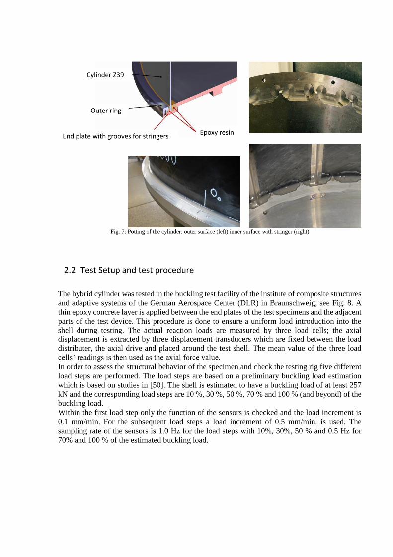
Fig. 7: Potting of the cylinder: outer surface (left) inner surface with stringer (right)
2.2 Test Setup and test procedure
The hybrid cylinder was tested in the buckling test facility of the institute of composite structures
and adaptive systems of the German Aerospace Center (DLR) in Braunschweig, see Fig. 8. A
thin epoxy concrete layer is applied between the end plates of the test specimens and the adjacent
parts of the test device. This procedure is done to ensure a uniform load introduction into the
shell during testing. The actual reaction loads are measured by three load cells; the axial
displacement is extracted by three displacement transducers which are fixed between the load
distributer, the axial drive and placed around the test shell. The mean value of the three load
cells’ readings is then used as the axial force value.
In order to assess the structural behavior of the specimen and check the testing rig five different
load steps are performed. The load steps are based on a preliminary buckling load estimation
which is based on studies in [50]. The shell is estimated to have a buckling load of at least 257
kN and the corresponding load steps are 10 %, 30 %, 50 %, 70 % and 100 % (and beyond) of the
buckling load.
Within the first load step only the function of the sensors is checked and the load increment is
0.1 mm/min. For the subsequent load steps a load increment of 0.5 mm/min. is used. The
sampling rate of the sensors is 1.0 Hz for the load steps with 10%, 30%, 50 % and 0.5 Hz for
70% and 100 % of the estimated buckling load.
Cylinder Z39
Epoxy resinEnd plate with grooves for stringers
Outer ring
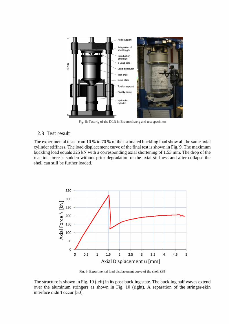
Fig. 8: Test rig of the DLR in Braunschweig and test specimen
2.3 Test result
The experimental tests from 10 % to 70 % of the estimated buckling load show all the same axial
cylinder stiffness. The load displacement curve of the final test is shown in Fig. 9. The maximum
buckling load equals 325 kN with a corresponding axial shortening of 1.53 mm. The drop of the
reaction force is sudden without prior degradation of the axial stiffness and after collapse the
shell can still be further loaded.
Fig. 9: Experimental load displacement curve of the shell Z39
The structure is shown in Fig. 10 (left) in its post-buckling state. The buckling half waves extend
over the aluminum stringers as shown in Fig. 10 (right). A separation of the stringer-skin
interface didn’t occur [50].
0
50
100
150
200
250
300
350
0 0,5 1 1,5 2 2,5 3 3,5 4 4,5 5
Axi
al F
orc
e N
[kN
]
Axial Displacement u [mm]
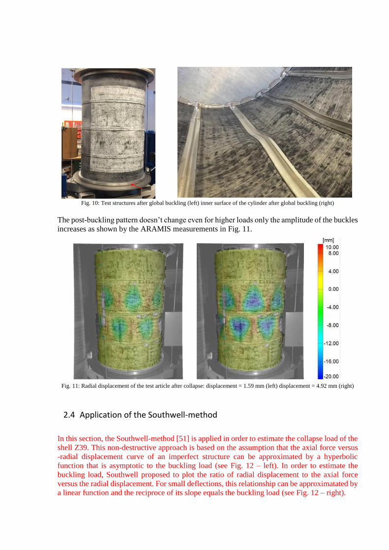
Fig. 10: Test structures after global buckling (left) inner surface of the cylinder after global buckling (right)
The post-buckling pattern doesn’t change even for higher loads only the amplitude of the buckles
increases as shown by the ARAMIS measurements in Fig. 11.
Fig. 11: Radial displacement of the test article after collapse: displacement = 1.59 mm (left) displacement = 4.92 mm (right)
2.4 Application of the Southwell-method
In this section, the Southwell-method [51] is applied in order to estimate the collapse load of the
shell Z39. This non-destructive approach is based on the assumption that the axial force versus
-radial displacement curve of an imperfect structure can be approximated by a hyperbolic
function that is asymptotic to the buckling load (see Fig. 12 – left). In order to estimate the
buckling load, Southwell proposed to plot the ratio of radial displacement to the axial force
versus the radial displacement. For small deflections, this relationship can be approximatated by
a linear function and the reciproce of its slope equals the buckling load (see Fig. 12 – right).
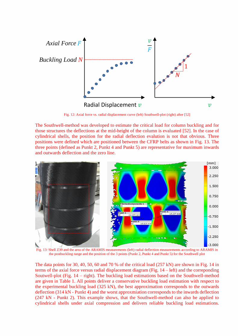
Fig. 12: Axial force vs. radial displacement curve (left) Southwell-plot (right) after [52]
The Southwell-method was developed to estimate the critical load for column buckling and for
those structures the deflections at the mid-height of the column is evaluated [52]. In the case of
cylindrical shells, the position for the radial deflection evalution is not that obvious. Three
positions were defined which are positioned between the CFRP belts as shown in Fig. 13. The
three points (defined as Punkt 2, Punkt 4 and Punkt 5) are representative for maximum inwards
and outwards deflection and the zero line.
Fig. 13: Shell Z39 and the area of the ARAMIS measurements (left) radial deflection measurements according to ARAMIS in
the postbuckling range and the position of the 3 points (Punkt 2, Punkt 4 and Punkt 5) for the Southwell plot
The data points for 30, 40, 50, 60 and 70 % of the critical load (257 kN) are shown in Fig. 14 in
terms of the axial force versus radial displacement diagram (Fig. 14 – left) and the correponding
Soutwell-plot (Fig. 14 – right). The buckling load estimations based on the Southwell-method
are given in Table 1. All points deliver a conservative buckling load estimation with respect to
the experimental buckling load (325 kN), the best approximation corresponds to the outwards
deflection (314 kN - Punkt 4) and the worst approxmiation corresponds to the inwards deflection
(247 kN - Punkt 2). This example shows, that the Southwell-method can also be applied to
cylindrical shells under axial compression and delivers reliable buckling load estimations.
Axial Force
Radial Displacement
Buckling Load N
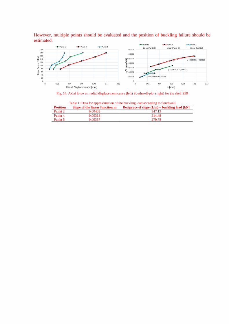
However, multiple points should be evaluated and the position of buckling failure should be
estimated.
Fig. 14: Axial force vs. radial displacement curve (left) Southwell-plot (right) for the shell Z39
Table 1: Data for approximation of the buckling load according to Southwell
Position Slope of the linear function m Reciproce of slope (1/m) ~ buckling load [kN]
Punkt 2 0.00405 247.13
Punkt 4 0.00318 314.48
Punkt 5 0.00357 279.78
0
20
40
60
80
100
120
140
160
180
200
0 0,02 0,04 0,06 0,08 0,1 0,12
Axi
al F
orc
e F
[kN
]
Radial Displacement v [mm]
Punkt 5 Punkt 4 Punkt 2
y = 0,00357x + 0,00013
y = 0,00318x + 0,00026
y = 0,00405x + 0,00007
0
0,0001
0,0002
0,0003
0,0004
0,0005
0,0006
0,0007
0 0,02 0,04 0,06 0,08 0,1 0,12
v/F
[mm
/kN
]
v [mm]
Punkt 5 Punkt 4 Punkt 2
Linear (Punkt 5) Linear (Punkt 4 ) Linear (Punkt 2)
3 Numerical analysis
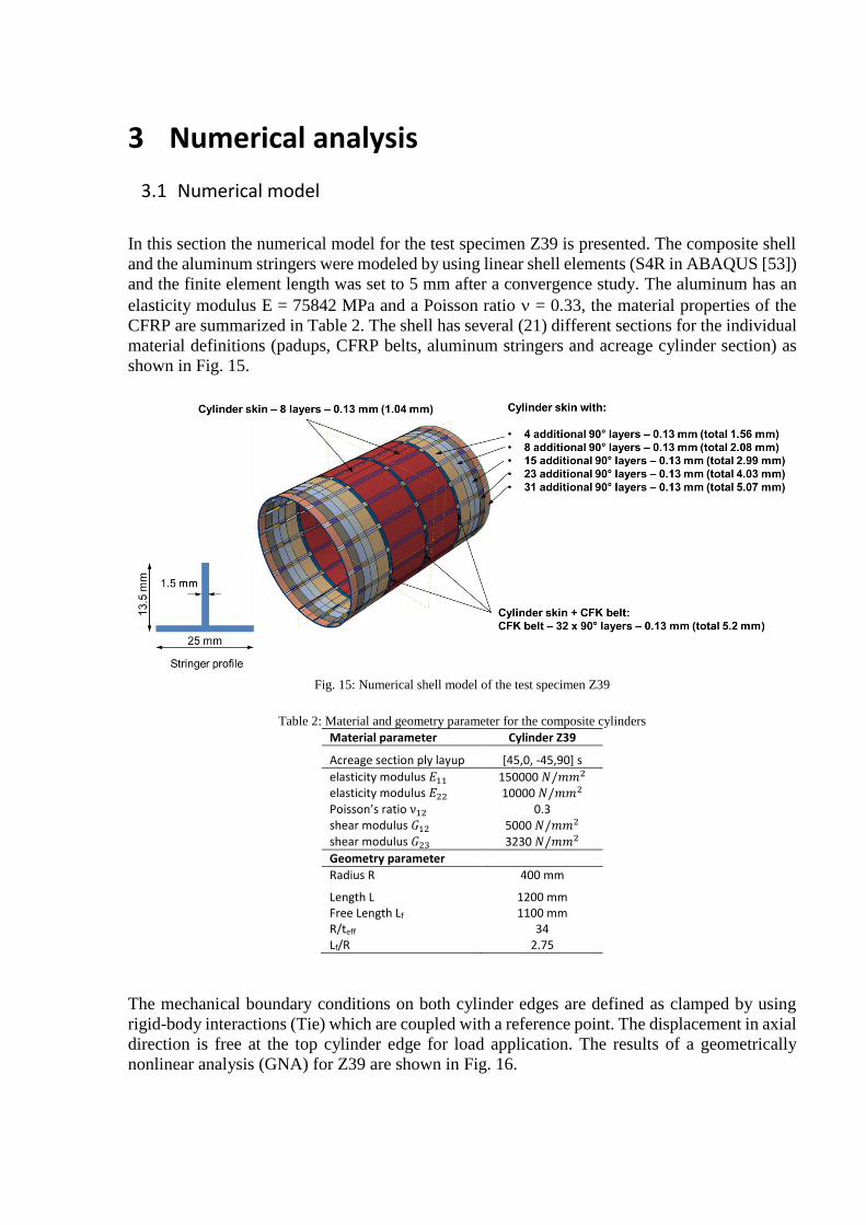
3.1 Numerical model
In this section the numerical model for the test specimen Z39 is presented. The composite shell
and the aluminum stringers were modeled by using linear shell elements (S4R in ABAQUS [53])
and the finite element length was set to 5 mm after a convergence study. The aluminum has an
elasticity modulus E = 75842 MPa and a Poisson ratio = 0.33, the material properties of the
CFRP are summarized in Table 2. The shell has several (21) different sections for the individual
material definitions (padups, CFRP belts, aluminum stringers and acreage cylinder section) as
shown in Fig. 15.
Fig. 15: Numerical shell model of the test specimen Z39
Table 2: Material and geometry parameter for the composite cylinders
Material parameter Cylinder Z39
Acreage section ply layup [45,0, -45,90] s
elasticity modulus 𝐸11 150000 /𝑚𝑚2 elasticity modulus 𝐸22 10000 /𝑚𝑚2 Poisson’s ratio ν12 0.3 shear modulus 𝐺12 5000 /𝑚𝑚2 shear modulus 𝐺23 3230 /𝑚𝑚2
Geometry parameter
Radius R 400 mm
Length L 1200 mm Free Length Lf 1100 mm R/teff 34 Lf/R 2.75
The mechanical boundary conditions on both cylinder edges are defined as clamped by using
rigid-body interactions (Tie) which are coupled with a reference point. The displacement in axial
direction is free at the top cylinder edge for load application. The results of a geometrically
nonlinear analysis (GNA) for Z39 are shown in Fig. 16.
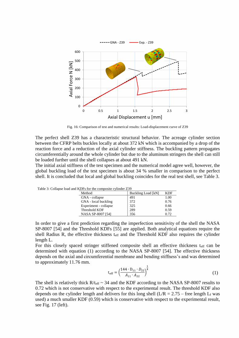
Fig. 16: Comparison of test and numerical results: Load-displacement curve of Z39
The perfect shell Z39 has a characteristic structural behavior. The acreage cylinder section
between the CFRP belts buckles locally at about 372 kN which is accompanied by a drop of the
reaction force and a reduction of the axial cylinder stiffness. The buckling pattern propagates
circumferentially around the whole cylinder but due to the aluminum stringers the shell can still
be loaded further until the shell collapses at about 491 kN.
The initial axial stiffness of the test specimen and the numerical model agree well, however, the
global buckling load of the test specimen is about 34 % smaller in comparison to the perfect
shell. It is concluded that local and global buckling coincides for the real test shell, see Table 3.
Table 3: Collapse load and KDFs for the composite cylinder Z39
Method Buckling Load [kN] KDF
GNA - collapse 491 1.00
GNA - local buckling 372 0.76
Experiment - collapse 325 0.66
Threshold KDF 289 0.59
NASA SP-8007 [54] 356 0.72
In order to give a first prediction regarding the imperfection sensitivity of the shell the NASA
SP-8007 [54] and the Threshold KDFs [55] are applied. Both analytical equations require the
shell Radius R, the effective thickness teff and the Threshold KDF also requires the cylinder
length L.
For this closely spaced stringer stiffened composite shell an effective thickness teff can be
determined with equation (1) according to the NASA SP-8007 [54]. The effective thickness
depends on the axial and circumferential membrane and bending stiffness’s and was determined
to approximately 11.76 mm.
teff = (
44 ∙ D11 ∙ 𝐷22
𝐴11 ∙ 𝐴22
)
14 (1)
The shell is relatively thick R/teff ~ 34 and the KDF according to the NASA SP-8007 results to
0.72 which is not conservative with respect to the experimental result. The threshold KDF also
depends on the cylinder length and delivers for this long shell (L/R = 2.75 – free length Lf was
used) a much smaller KDF (0.59) which is conservative with respect to the experimental result,
see Fig. 17 (left).
0
100
200
300
400
500
600
0 0.5 1 1.5 2 2.5 3
Axi
al F
orc
e N
[kN
]
Axial Displacement u [mm]
GNA - Z39 Exp. - Z39
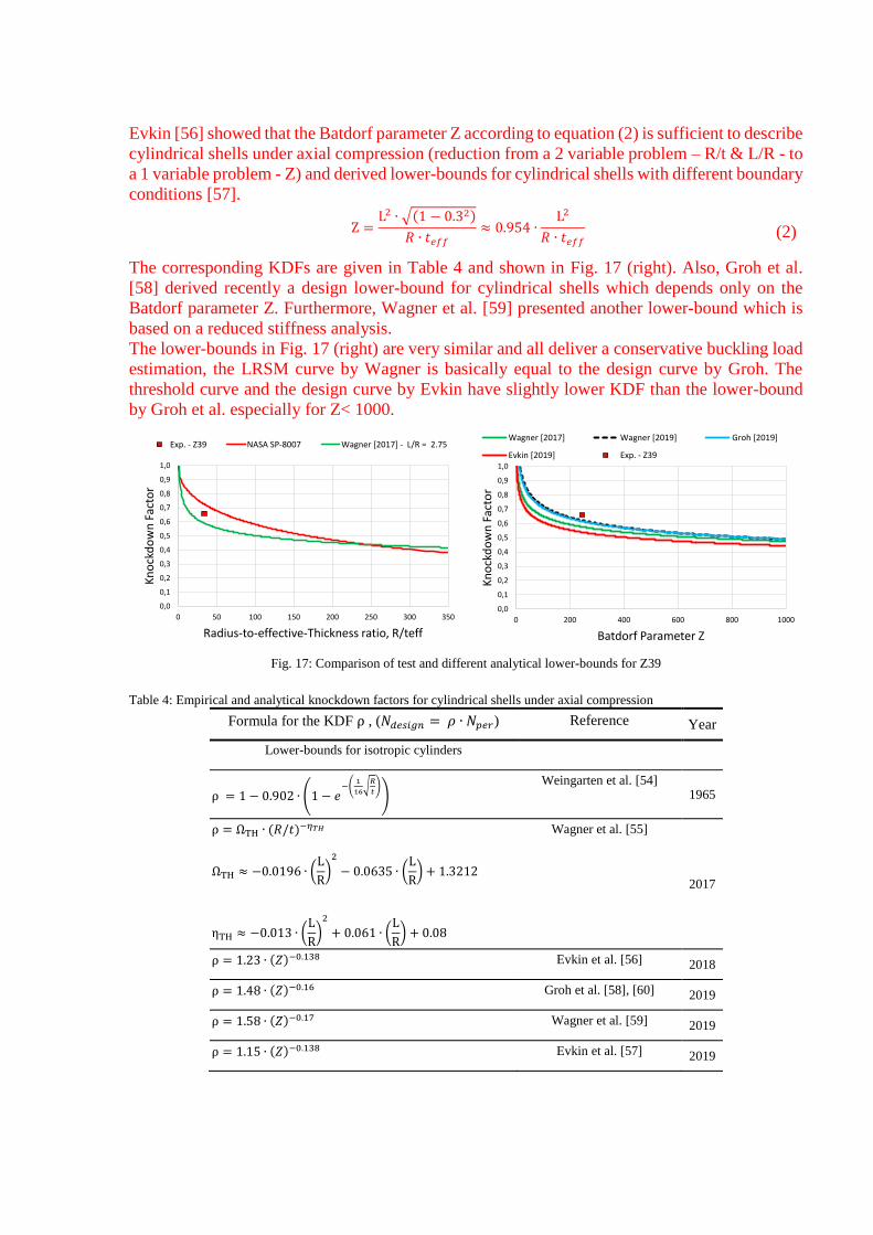
Evkin [56] showed that the Batdorf parameter Z according to equation (2) is sufficient to describe
cylindrical shells under axial compression (reduction from a 2 variable problem – R/t & L/R - to
a 1 variable problem - Z) and derived lower-bounds for cylindrical shells with different boundary
conditions [57].
Z =
L2 ∙ √( − 0.32)
𝑅 ∙ 𝑡𝑒𝑓𝑓≈ 0.954 ∙
L2
𝑅 ∙ 𝑡𝑒𝑓𝑓 (2)
The corresponding KDFs are given in Table 4 and shown in Fig. 17 (right). Also, Groh et al.
[58] derived recently a design lower-bound for cylindrical shells which depends only on the
Batdorf parameter Z. Furthermore, Wagner et al. [59] presented another lower-bound which is
based on a reduced stiffness analysis.
The lower-bounds in Fig. 17 (right) are very similar and all deliver a conservative buckling load
estimation, the LRSM curve by Wagner is basically equal to the design curve by Groh. The
threshold curve and the design curve by Evkin have slightly lower KDF than the lower-bound
by Groh et al. especially for Z< 1000.
Fig. 17: Comparison of test and different analytical lower-bounds for Z39
Table 4: Empirical and analytical knockdown factors for cylindrical shells under axial compression
Formula for the KDF ρ , ( 𝑑𝑒𝑠𝑖𝑔𝑛 = 𝜌 ∙ 𝑝𝑒𝑟) Reference Year
Lower-bounds for isotropic cylinders
ρ = − 0.902 ∙ ( − 𝑒−(
1
16√𝑅
𝑡))
Weingarten et al. [54] 1965
ρ = ΩTH ∙ (𝑅/𝑡)−𝜂𝑇𝐻
ΩTH ≈ −0.0 96 ∙ (L
R)2
− 0.0635 ∙ (L
R) + .32 2
ηTH ≈ −0.0 3 ∙ (L
R)2
+ 0.06 ∙ (L
R) + 0.08
Wagner et al. [55]
2017
ρ = .23 ∙ (𝑍)−0.138 Evkin et al. [56] 2018
ρ = .48 ∙ (𝑍)−0.16 Groh et al. [58], [60] 2019
ρ = .58 ∙ (𝑍)−0.17 Wagner et al. [59] 2019
ρ = . 5 ∙ (𝑍)−0.138 Evkin et al. [57] 2019
0,0
0,1
0,2
0,3
0,4
0,5
0,6
0,7
0,8
0,9
1,0
0 50 100 150 200 250 300 350
Kn
ock
do
wn
Fac
tor
Radius-to-effective-Thickness ratio, R/teff
Exp. - Z39 NASA SP-8007 Wagner [2017] - L/R = 2.75
0,0
0,1
0,2
0,3
0,4
0,5
0,6
0,7
0,8
0,9
1,0
0 200 400 600 800 1000
Kn
ock
do
wn
Fac
tor
Batdorf Parameter Z
Wagner [2017] Wagner [2019] Groh [2019]
Evkin [2019] Exp. - Z39
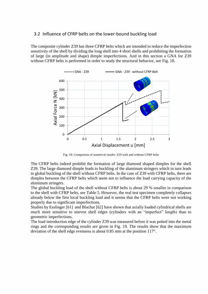
3.2 Influence of CFRP belts on the lower-bound buckling load
The composite cylinder Z39 has three CFRP belts which are intended to reduce the imperfection
sensitivity of the shell by dividing the long shell into 4 short shells and prohibiting the formation
of large (in amplitude and shape) dimple imperfections. And in this section a GNA for Z39
without CFRP belts is performed in order to study the structural behavior, see Fig. 18.
Fig. 18: Comparison of numerical results: Z39 with and without CFRP belts
The CFRP belts indeed prohibit the formation of large diamond shaped dimples for the shell
Z39. The large diamond dimple leads to buckling of the aluminum stringers which in turn leads
to global buckling of the shell without CFRP belts. In the case of Z39 with CFRP belts, there are
dimples between the CFRP belts which seem not to influence the load carrying capacity of the
aluminum stringers.
The global buckling load of the shell without CFRP belts is about 29 % smaller in comparison
to the shell with CFRP belts, see Table 5. However, the real test specimen completely collapses
already below the first local buckling load and it seems that the CFRP belts were not working
properly due to significant imperfections.
Studies by Esslinger [61] and Blachut [62] have shown that axially loaded cylindrical shells are
much more sensitive to uneven shell edges (cylinders with an “imperfect” length) than to
geometric imperfections.
The load introduction edge of the cylinder Z39 was measured before it was potted into the metal
rings and the corresponding results are given in Fig. 19. The results show that the maximum
deviation of the shell edge evenness is about 0.85 mm at the position 117°.
0
100
200
300
400
500
600
0 0.5 1 1.5 2 2.5 3
Axi
al F
orc
e N
[kN
]
Axial Displacement u [mm]
GNA - Z39 GNA - Z39 - without CFRP Belt
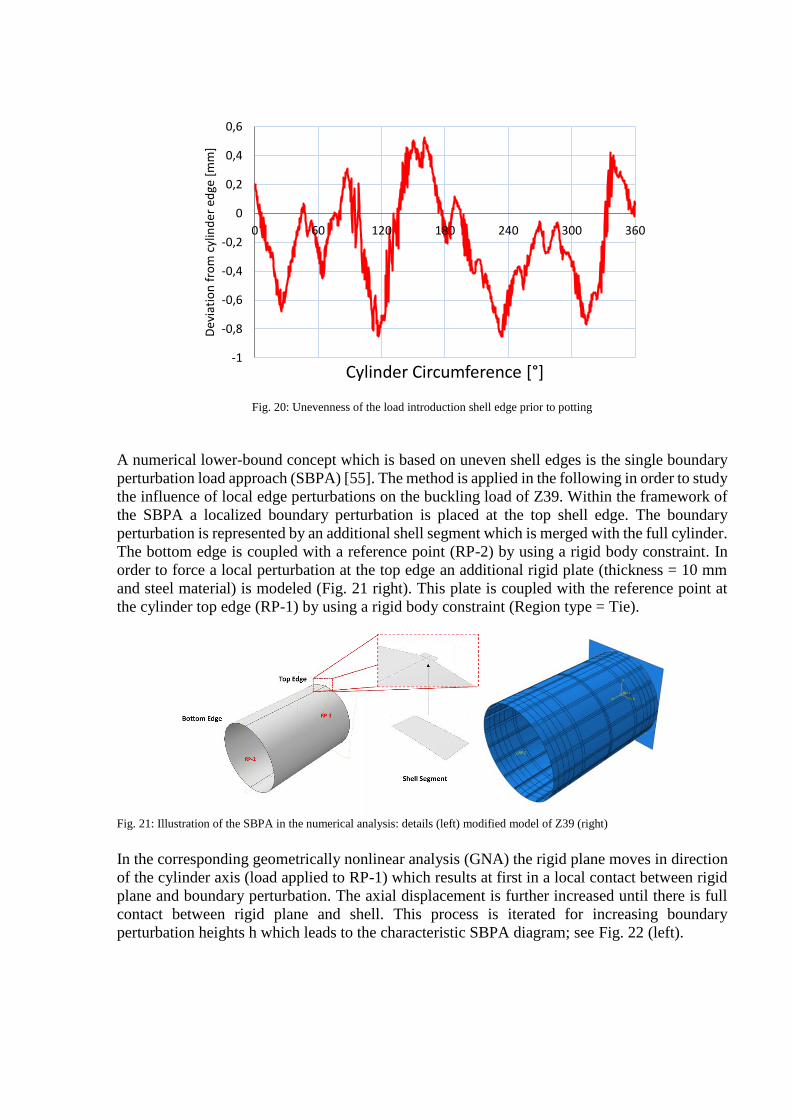
Fig. 20: Unevenness of the load introduction shell edge prior to potting
A numerical lower-bound concept which is based on uneven shell edges is the single boundary
perturbation load approach (SBPA) [55]. The method is applied in the following in order to study
the influence of local edge perturbations on the buckling load of Z39. Within the framework of
the SBPA a localized boundary perturbation is placed at the top shell edge. The boundary
perturbation is represented by an additional shell segment which is merged with the full cylinder.
The bottom edge is coupled with a reference point (RP-2) by using a rigid body constraint. In
order to force a local perturbation at the top edge an additional rigid plate (thickness = 10 mm
and steel material) is modeled (Fig. 21 right). This plate is coupled with the reference point at
the cylinder top edge (RP-1) by using a rigid body constraint (Region type = Tie).
Fig. 21: Illustration of the SBPA in the numerical analysis: details (left) modified model of Z39 (right)
In the corresponding geometrically nonlinear analysis (GNA) the rigid plane moves in direction
of the cylinder axis (load applied to RP-1) which results at first in a local contact between rigid
plane and boundary perturbation. The axial displacement is further increased until there is full
contact between rigid plane and shell. This process is iterated for increasing boundary
perturbation heights h which leads to the characteristic SBPA diagram; see Fig. 22 (left).
-1
-0,8
-0,6
-0,4
-0,2
0
0,2
0,4
0,6
0 60 120 180 240 300 360
Dev
iati
on
fro
m c
ylin
der
ed
ge [
mm
]
Cylinder Circumference [°]
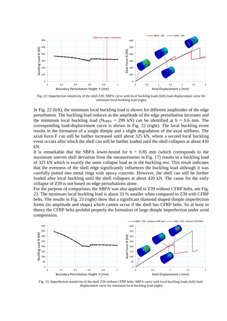
Fig. 22: Imperfection sensitivity of the shell Z39: SBPA curve with local buckling loads (left) load-displacement curve for
minimum local buckling load (right)
In Fig. 22 (left), the minimum local buckling load is shown for different amplitudes of the edge
perturbation. The buckling load reduces as the amplitude of the edge perturbation increases and
the minimum local buckling load (NSBPA = 299 kN) can be identified at h = 0.6 mm. The
corresponding load-displacement curve is shown in Fig. 22 (right). The local buckling event
results in the formation of a single dimple and a slight degradation of the axial stiffness. The
axial force F can still be further increased until about 325 kN, where a second local buckling
event occurs after which the shell can still be further loaded until the shell collapses at about 430
kN.
It is remarkable that the SBPA lower-bound for h = 0.85 mm (which corresponds to the
maximum uneven shell deviation from the measurements in Fig. 17) results in a buckling load
of 325 kN which is exactly the same collapse load as in the buckling test. This result indicates
that the evenness of the shell edge significantly influences the buckling load although it was
carefully potted into metal rings with epoxy concrete. However, the shell can still be further
loaded after local buckling until the shell collapses at about 420 kN. The cause for the early
collapse of Z39 is not based on edge perturbations alone.
For the purpose of comparison, the SBPA was also applied to Z39 without CFRP belts, see Fig.
23. The minimum local buckling load is about 33 % smaller when compared to Z39 with CFRP
belts. The results in Fig. 23 (right) show that a significant diamond shaped dimple imperfection
forms (in amplitude and shape) which cannot occur if the shell has CFRP belts. So at least in
theory the CFRP belts prohibit properly the formation of large dimple imperfection under axial
compression.
Fig. 23: Imperfection sensitivity of the shell Z39 without CFRP belts: SBPA curve with local buckling loads (left) load-
displacement curve for minimum local buckling load (right)
0
100
200
300
400
500
600
0 0,5 1 1,5 2 2,5 3
Axi
al F
orc
e N
[kN
]
Axial Displacement u [mm]
SBPA - Z39 GNA - Z39
0
100
200
300
400
500
600
0 0,2 0,4 0,6 0,8 1
Bu
cklin
g Lo
ad N
[kN
]
Boundary Perturbation Height h [mm]
Maximum edge uneveness
0
50
100
150
200
250
300
350
400
0 0.5 1 1.5 2
Axi
al F
orc
e N
[kN
]
Axial Displacement u [mm]
SBPA - Z39 - without CFRP belt GNA - Z39 - without CFRP Belt
0
50
100
150
200
250
300
350
400
0 0.2 0.4 0.6 0.8 1
Bu
cklin
g Lo
ad N
[kN
]
Boundary Perturbation Height h [mm]
This analysis shows that even significant imperfections don’t lead to early collapse of the shell
that means there seem to be other causes which are studied in section 3.3.
Table 5: Buckling load and KDFs for the composite cylinder Z39 with and without CFRP belts
Z39 Z39 – without CFRP belts
Method Buckling Load [kN] KDF Buckling Load [kN] KDF
GNA - collapse 491 1.00 350 1.00
GNA - local buckling 372 0.76 - -
SBPA – local buckling (min.) 299 0.60 198 0.56
Experiment - collapse 325 0.66 - -
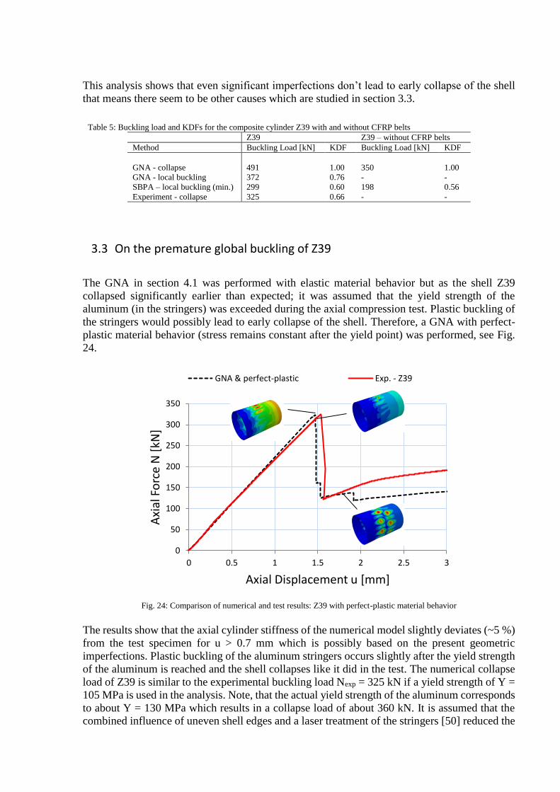
3.3 On the premature global buckling of Z39
The GNA in section 4.1 was performed with elastic material behavior but as the shell Z39
collapsed significantly earlier than expected; it was assumed that the yield strength of the
aluminum (in the stringers) was exceeded during the axial compression test. Plastic buckling of
the stringers would possibly lead to early collapse of the shell. Therefore, a GNA with perfect-
plastic material behavior (stress remains constant after the yield point) was performed, see Fig.
24.
Fig. 24: Comparison of numerical and test results: Z39 with perfect-plastic material behavior
The results show that the axial cylinder stiffness of the numerical model slightly deviates (~5 %)
from the test specimen for u > 0.7 mm which is possibly based on the present geometric
imperfections. Plastic buckling of the aluminum stringers occurs slightly after the yield strength
of the aluminum is reached and the shell collapses like it did in the test. The numerical collapse
load of Z39 is similar to the experimental buckling load Nexp = 325 kN if a yield strength of Y =
105 MPa is used in the analysis. Note, that the actual yield strength of the aluminum corresponds
to about Y = 130 MPa which results in a collapse load of about 360 kN. It is assumed that the
combined influence of uneven shell edges and a laser treatment of the stringers [50] reduced the
0
50
100
150
200
250
300
350
0 0.5 1 1.5 2 2.5 3
Axi
al F
orc
e N
[kN
]
Axial Displacement u [mm]
GNA & perfect-plastic Exp. - Z39

yield strength of the aluminum which in turn resulted in the experimental buckling load of 325
kN.
4 Conclusion and Outlook
A hybrid composite cylinder with aluminum stringers was presented in this article. In addition,
the cylinder has three CFRP belts which reduce the imperfection sensitivity of the shell. The
cylinder is denominate as Z39 and was examined before testing by means of photogrammetry.
Reaction loads and axial shortening were recorded during testing and the structural behavior was
monitored with the ARAMIS system.
Numerical simulations were performed for the shell which showed that the experimental test
shell buckled much early than otherwise predicted in the simulation. The corresponding
knockdown factor for the shell results to 0.66.
The Southwell-method was applied in order to estimate the collapse load of the cylinder. The
results show that the Southwell-method delivers conservative buckling load estimations.
However, the magnitude of the buckling load significantly depends on the evaluated radial
displacement position.
A series of numerical analysis were performed to assess the imperfection sensitivity of the shell
with / without CFRP belts and determine the cause for the premature global buckling of Z39.
The results showed that the CFRP belts successfully decrease the imperfection sensitivity of the
shell, by prohibiting the formation of large dimple imperfections, and lead to an about 33 %
higher lower-bound buckling load.
Measurements of the unevenness of the shell edge were performed which showed a maximum
peak unevenness of 0.85 mm. The edge perturbation approach (SBPA) was applied to the
cylinder Z39 and it could be shown that an edge perturbation with a height of 0.85 mm leads to
a local buckling load which exactly matches the collapse load from the buckling test. However,
in the numerical simulation with the SBPA and h = 0.85 mm, the cylinder could still be further
loaded after local buckling until the shell collapses at about 420 kN. The unevenness of the shell
edge may be a cause for the lower than expected local buckling load but not for early collapse
of the shell.
This result is nevertheless interesting because the test article was carefully potted into metal rings
with epoxy concrete and this unevenness of the shell edge should have been negligible. In future
buckling tests, the shell edge should be carefully trimmed before potting in order to avoid this
problem.
The cause for the earlier than expected collapse of Z39 was found to be plastic buckling of the
aluminum stringers. The cylinder Z39 should have withstood local buckling of the composite
skin but due to exceeding the yield strength of the aluminum, the shell collapsed completely. It
is assumed that the laser treatment of the aluminum stringers reduced the yield strength of the
material which in turn lead to early collapse.
The presented new shell architecture and the corresponding buckling test are a base for future
high-performance composite shells which are used in future launch-vehicle structures.
Acknowledgement: The research work was carried out at DLR as part of the research association Cryogenic Upper
Stage. The work presented is based on shell design studies performed by the MT Aerospace AG
(www.mt-aerospace.de). The support of MT Aerospace, in particular of Birte Höck, Thomas
Link, Ulrich Glaser and Guenther Schullerer, is gratefully acknowledged.
5 References
[1] M. H. Hilburger and J. H. J. and Starnes, "High-fidelity Analysis of Compression-loaded Composite Shells," Proceedings of the 42st AIAA/ASME/ASCE/AHS/ASC Structures, Structural Dynamics, and Materials Conference, pp. AIAA Paper No. 2001-1394, 2001.
[2] H. Abramovich, Stability and Vibrations of Thin Walled Composite Structures, Elsevier Science & Technology ; Woodhead Publishing, 2017.
[3] M. Schultz and M. Nemeth, "Buckling Imperfection Sensitivity of Axially compressed orthotropic cylinders".51st AIAA/ASME/ASCE/AHS/ASC Structures, Structural Dynamics, and Materials Conference<BR>18th 12 - 15 April 2010, Orlando, Florida.
[4] M. R. Schultz, D. W. Sleight, D. E. Myers, W. A. J. Waters, P. B. Chunchu, A. W. Lovejoy and M. W. Hilburger, "Buckling Design and Imperfection Sensitivity of Sandwich Composite Launch-Vehicle Shell Structures," Conference: Proceedings of the American Society for Composites: Thirty-First Technical Conference, At Williamsburg, VA, 2016.
[5] W. T. Koiter, The Stability of Elastic Equilibrium [PhD thesis] - 1945 [in Dutch], TH Delft, Ed., Englisch Translation NASA TTF-10; 1967, p. 1–833.
[6] H. Wagner, C. Hühne, K. Rohwer, S. Niemann and M. Wiedemann, "Stimulating the realistic worst case buckling scenario of axially compressed cylindrical composite shells," Composite Structures, vol. 160, pp. 1095-1104, 2017.
[7] H. Wagner and C. R. K. Hühne, "Towards robust knockdown factors for the design of conical shells under axial compression".International Journal of Mechanical Sciences, 2018, Vol. 146-147, pp. 60-80.
[8] H. Wagner, C. Hühne, S. Niemann, K. Tian, B. Wang and P. Hao, "Robust knockdown factors for the design of cylindrical shells under axial compression: Analysis and modeling of stiffened and unstiffened cylinders," Thin-Walled Struct, 127 (June 2018), pp. 629-645.
[9] H. Wagner, C. Hühne and S. Niemann, "Robust knockdown factors for the design of spherical shells under external pressure: Development and validation," International Journal of Mechanical Sciences, Volume 141, 2018, Pages 58-77.
[10] H. Wagner, C. Hühne, J. Zhang and W. R. Tang, "Geometric imperfection and lower-bound analysis of spherical shells under external pressure," Thin-walled Structures, 2019, Volume 143, October 2019, 106195.
[11] M. Hilburger, M. Nemeth and J. J. Starnes, "Shell Buckling Design Criteria Based on Manufacturing Imperfection Signatures," NASA/TM-2004-212659, 2004.
[12] D. B. Muggeridge and R. C. Tennyson, "Buckling of axisymmetric imperfect circular cylindrical shells underaxial compression," AIAA Journal, vol. 7, p. 2127–2131, 1969.
[13] J. Arbocz, "The imperfections data bank, a means to obtain realistic buckling loads," In Ramm E. Buckling of shells, 1982.
[14] H. Fan, "Critical buckling load prediction of axially compressed cylindrical shell based on non-destructive probing method".Thin-Walled Structures, Volume 139, June 2019, Pages 91-104.
[15] C. Hühne, R. Rolfes and J. Teßmer, "A new approach for robust design of composite cylindrical shells under axial compression," in Proceedings of the European Conference on Spacecraft Structures, 2005.
[16] B. Wang, X. Ma, H. Pang, Y. Sun, K. Tian, G. Li, K. Zhang, L. Jiang and J. Guo, "Improved knockdown factors for composite cylindrical shells with delamination and geometric imperfections," Composites Part B: Engineering, Vol. 163, 2019, pp. 314-323.
[17] H. Wagner, Hühne, S. Niemann and R. Khakimova, "Robust design criterion for axially loaded cylindrical shells - Simulation and Validation," Thin-Walled Structures 115, pp 154-162, 2017.
[18] C. Hühne, R. Zimmermann, R. Rolfes and B. Gier, Loading imperfections – Experiments and computations, Euromech colloquium 424, 2001.
[19] C. Hühne, R. Zimmermann, R. Rolfes and B. Geier, "SENSITIVITIES TO GEOMETRICAL AND LOADING IMPERFECTIONS ON BUCKLING OF COMPOSITE CYLINDRICAL SHELLS," In Proceedings of European Conference on Spacecraft, 2002.
[20] R. Wagner and C. Hühne, "A NEW DESIGN CONCEPT FOR CYLINDRICAL COMPOSITE SHELLS UNDER AXIAL COMPRESSION," in Proceedings of the European Conference on Composite Materials - ECCM16, Sevillia, Spain, 2014.
[21] H. Wagner, C. Hühne and S. Niemann, "Constant Single-Buckle Imperfection Principle to determine a lower bound for the buckling load of unstiffened composite cylinders under axial compression," Composite Structures, vol. 139, pp. 120-129, 2016.
[22] M. W. Hilburger, A. E. Lovejoy, R. P. Thornburgh and C. Rankin, "Design and Analysis of Subscale and Full-Scale Buckling-Critical Cylinders for Launch Vehicle Technology Development," AIAA Paper 2012-1865, NF1676L-13285, 2012.
[23] M. W. Hilburger, W. T. Haynie, A. E. Lovejoy, M. G. Roberts, J. P. Norris, W. A. Waters and H. M. Herring, "Subscale and Full-Scale Testing of Buckling-Critical Launch Vehicle Shell Structures," AIAA Paper 2012-1688, NF1676L-13284.
[24] M. W. Hilburger, W. A. J. Waters and W. T. Haynie, "Buckling Test Results from the 8-Foot-Diameter Orthogrid-Stiffened Cylinder Test Article TA01. [Test Dates: 19-21 November 2008]," NASA/TP-2015-218785, L-20490, NF1676L-20067, 2015.
[25] M. W. Hilburger, W. A. J. Waters, W. T. Haynie and R. P. Thornburgh, "Buckling Test Results and Preliminary Test and Analysis Correlation from the 8-Foot-Diameter Orthogrid-Stiffened Cylinder Test Article TA02," NASA/TP-2017-219587, L-20801, NF1676L-26704, 2017.
[26] M. Schultz, D. Sleight, N. Gardner, M. Rudd, M. Hilburger, T. Palm and N. Oldfield, "Test and Analysis of a Buckling-Critical Large-Scale Sandwich Composite Cylinder," 2018 AIAA/ASCE/AHS/ASC Structures, Structural Dynamics, and Materials Conference, AIAA SciTech Forum, (AIAA 2018-1693).
[27] M. R. Schultz, D. W. Sleight, D. E. Myers, W. A. Waters, P. B. Chunchu, A. W. Lovejoy and M. W. Hilburger, "Buckling Design and Imperfection Sensitivity of Sandwich Composite Launch-Vehicle Shell Structures," Conference: Proceedings of the American Society for Composites: Thirty-First Technical Conference, At Williamsburg, VA, 2016.
[28] "SBKF. NASA shell buckling knockdown factor project; 2017. Available from:<https://www.nasa.gov/offices/nesc/home/Feature_ShellBuckling_Test.html> [cited 2017 11-05-2017]".
[29] M. Hilburger, "Developing the next generation shell buckling design factors and technologies," 53rd AIAA/ASME/ASCE/AHS/ASC structures, structural dynamics and materials conference, Honolulu; 2012.
[30] M. W. Hilburger, "On the Development of Shell Buckling Knockdown Factors for Stiffened Metallic Launch Vehicle Cylinders," 2018 AIAA/ASCE/AHS/ASC Structures, Structural Dynamics, and Materials Conference.
[31] M. Hilburger, M. C. Lindell, W. A. Waters and N. W. Gardner, "Test and Analysis of Buckling-Critical Stiffened Metallic Launch Vehicle Cylinders," 2018 AIAA/ASCE/AHS/ASC Structures, Structural Dynamics, and Materials Conference.
[32] R. Degenhardt, R. Zimmermann, A. Kling and D. Wilckens, "New Robust Design Guideline for imperfection sensitive composite launcher structures," in 3rd CEAS Congress, Venice, Italy, 2011.
[33] R. Khakimova, C. Warren, R. Zimmerman, S. Castro and R. Degenhardt, "The single perturbation load approach applied to imperfection sensitive conical composite structures," Thin-Walled Structures, vol. 84, pp. 369-377, 2014.
[34] R. Degenhardt, A. Bethge, A. Kling, R. Zimmermann and K. Rohwer, "Probabilistic approach for improved buckling knock-down factors of CFRP cylindrical shells," in Proceeding of 18th Engineering Mechanics Division Conference, 2007.
[35] E. Skukis, O. Ozolins, K. Kalnins and M. Arbelo, "Experimental Test for Estimation of Buckling Load on Unstiffened Cylindrical shells by Vibration Correlation Technique," Procedia Engineering, vol. 172, pp. 1023-1030, 2017.
[36] E. Skukis, K. Kalnins and O. Ozolins, "Application of Vibration Correlation Technique for Open Hole Cylinders," Nonlinear Dynamics–2016 (ND-KhPI2016) : proceedings of 5th International Conference, dedicated to the 90th anniversary of Academician V. L. Rvachev, pp. 377-383, 2016.
[37] R. Degenhardt, A. Kling, R. Zimmermann and F. Oderman, Dealing with imperfection sensitivity of composite structures prone to buckling, in "Advances in Computational Stability Analysis" ; book edited by Safa Bozkurt Coskun, ISBN 978-953-51-0673-9, 2012.
[38] R. Khakimova, S. Castro, D. R. K. Wilckens and R. Degenhardt, "Buckling of axially compressed CFRP cylinders with and without additional lateral load: Experimental and numerical investigation," Thin-Walled Structures, vol. 119, pp. 178-189, 2017.
[39] R. Khakimova, R. Zimmermann, D. Wilckens, K. Rohwer and R. Degenhardt, "Buckling of axially compressed CFRP truncated cones with additional lateral load: Experimental and numerical investigation," Composite Structures, vol. 157, pp. 436-447, 2016.
[40] R. Khakimova, D. Wilckens, J. Reichardt and R. Degenhardt, "Buckling of axially compressed CFRP truncated cones: Experimental and numerical investigation," Composite Structures, vol. 146, pp. 232-247, 2016.
[41] H. Wagner, C. Hühne and S. Niemann, "Robust knockdown factors for the design of axially loaded cylindrical and conical composite shells - Development and Validation," Composite Structures, vol. 173, no. 10.1016/j.compstruct.2017.02.031, pp. 281-303, 2017.
[42] D. Sleight, A. Satyanarayana and M. R. Schultz, "Buckling Imperfection Sensitivity of Conical Sandwich Composite Structures for Launch-Vehicles," 2018 AIAA/ASCE/AHS/ASC Structures, Structural Dynamics, and Materials Conference.
[43] R. Khakimova, "Ply topology based design concept for composite truncated cones manufactured by tape laying".DIssertation, TU-Braunschweig, 2017.
[44] S. White and P. Weaver, "Towards imperfection insensitive buckling response of shell structures-shells," The Aeronautical Journal, Volume 120, Issue 1224, February 2016, pp 233 - 253.
[45] H. Wagner, H. Köke, S. Dähne, S. Niemann, C. Hühne and R. Khakimova, "Decision tree-based machine learning to optimize the laminate stacking of composite cylinders for maximum buckling load and minimum imperfection sensitivity".Composite Structures, Volume 220, 15 July 2019, Pages 45-63.
[46] C. Hühne, R. Rolfes, E. Breitbach and J. Teßmer, "Robust design of composite cylindrical shells under axial compression — Simulation and validation," Thin-Walled Structures, vol. 46, p. 947–962, 2008.
[47] E. Labans, H. Abramovich and C. Bisagni, "An experimental vibration-buckling investigation on classical and variable angle tow composite shells under axial compression," Journal of Sound and Vibration, Volume 449, 9 June 2019, Pages 315-329.
[48] X. Ning and S. Pellegrino, "Experiments on imperfection insensitive axially loaded cylindrical shells," International Journal of Solids and Structures, Volumes 115–116, 1 June 2017, Pages 73-86.
[49] K. Yadav and S. Gerasimidis, "Imperfection insensitive thin steel tubular shells under bending," Proceedings of the Annual Stability Conference Structural Stability Research Council St. Louis, Missouri, April 2-5, 2019.
[50] B. Höck, T. Link, U. Glaser, S. Ehard, E. Petersen and G. Schullerer, "Development, Manufacturing and Testing of CFRP Aluminum Hybrid Structures for Aerospace Applications," http://publikationen.dglr.de/?tx_dglrpublications_pi1[document_id]=450170, p. 8, 2017.
[51] R. V. Southwell, "On the analysis of experimental observations in problems of elastic stability," Proc. R. Soc. Lond. A: Math., Phys. Eng. Sci., 135 (828) (1932), pp. 601-616.
[52] G. dos Santos, L. Gardner and M. Kucukler, "A method for the numerical derivation of plastic collapse loads," Thin-Walled Structures, Volume 124, March 2018, Pages 258-277.
[53] Dassault Systems, ABAQUS 6.13—Software Package, 2013.
[54] V. I. Weingarten, E. J. Morgan and P. Seide, "Elastic stability of thin-walled cylindrical and conical shells under axial compression," AIAA Journal, vol. 3, pp. 500-505, 1965.
[55] H. Wagner and C. Hühne, "Robust knockdown factors for the design of cylindrical shells under axial compression: potentials, practical application and reliability analysis," International Journal of Mechanical Sciences 135, pp. 410-430, 2018.
[56] A. Evkin, "Local Buckling of Cylindrical Shells. Pogorelov’s Geometrical Method," Andrianov I., Manevich A., Mikhlin Y., Gendelman O. (eds) Problems of Nonlinear Mechanics and Physics of Materials. Advanced Structured Materials, vol 94. Springer, Cham.
[57] A. Evkin, V. Krasovsky, O. Lykhachova and V. Marchenko, "Local buckling of axially compressed cylindrical shells with different boundary conditions," Thin-Walled Structures, Volume 141, August 2019, Pages 374-388.
[58] R. Groh and A. Pirrera, "On the role of localizations in buckling of axially compressed cylinders, 475, Proc. R. Soc. A, 2019," https://doi.org/10.1098/rspa.2019.0006.
[59] H. Wagner, E. Sosa, C. Hühne, T. Ludwig and J. Croll, "Robust design of imperfection sensitive thin-walled shells under axial compression, bending or external pressure," International Journal of mechanical sciences, 2019, Vol. 156, 205-220.
[60] R. Groh and A. Pirrera, "Localised post-buckling states of axially compressed cylinders and their energy barriers," AIAA Scitech 2019 Forum. January .
[61] M. Esslinger and H. Melzer, "Über den Einfluß von Bodensenkungen auf den Spannungs- und Deformationszustand von Silos," Stahlbau 49, 1980, 129-134.
[62] J. Blachut, "Buckling of axially compressed cylinders with imperfect length," Computers and Structures 88, 2010, 365-374.
Recommended