Langley Research CenterAATT Project
Structural Implementations of
Leading‐Edge Noise Reduction Devices
Travis Turner
Airframe Noise Technical Challenge
AATT Project
Acoustics Technical Working Group Meeting
April 21-22, 2015
https://ntrs.nasa.gov/search.jsp?R=20160007338 2018-06-02T00:49:28+00:00Z
Langley Research CenterAATT Project
Aeroacoustics
• David Lockard
• Mehdi Khorrami
• Craig Streett
• John Lin
Acknowledgements
Materials & Structures
• Travis Turner
• Jim Moore
• Mia Siochi
• Jin Ho Kang, NIA
• Reggie Kidd, AMA
• Dave Long, AMA
• Darren Hartl, TAMU
• Will Scholten, TAMU
Prototype Development
• George Hilton
• Larry Becker, NG
• Ron Penner, STC
• Rick Thomas, STC
NASA AATT Project2
SMA Components
• Joe Kain, JM
• Carlos Pimentel, JM
Langley Research CenterAATT Project
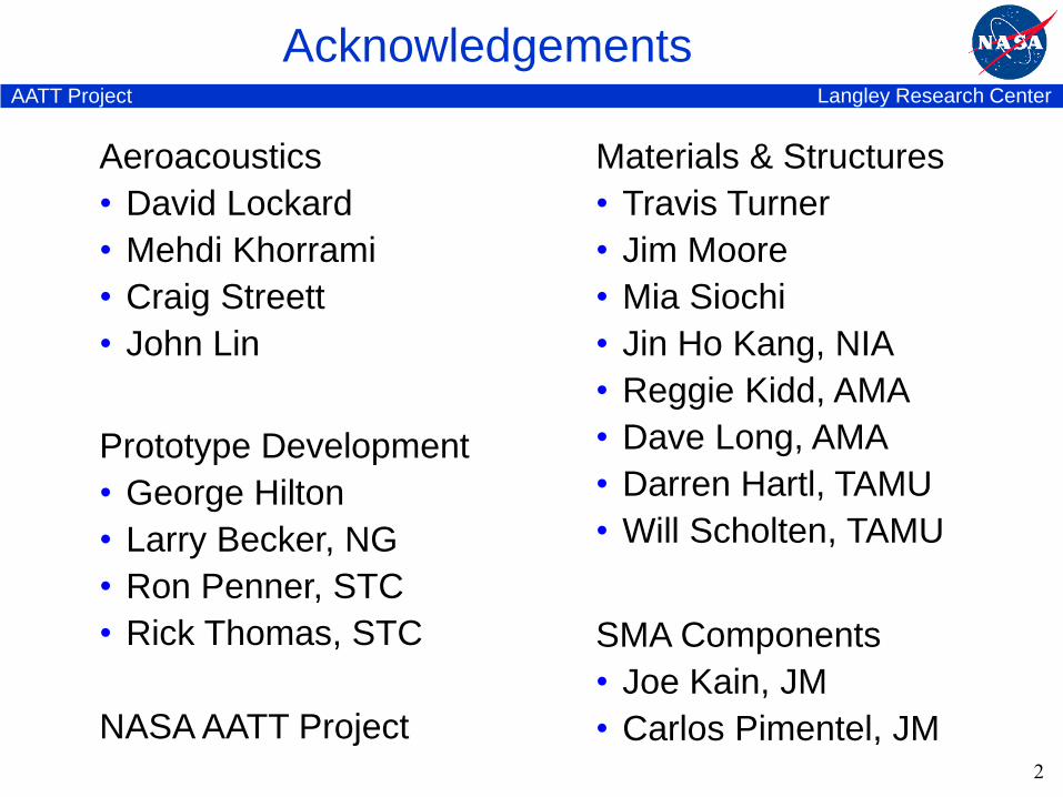
Airframe Noise Mitigation Concepts
Background
• Airframe noise comparable to engine noise during approach
• Slats & flaps are major contributorsFlaps
Slats
Gear
Airframe Noise Sources
Wing Leading Edge Cross Section
Characteristics
• Multi-element airfoil increases lift
• Unsteady flow creates noise
Challenge: Reduce airframe noise w/o aero compromise (cruise or landing)Slat
Main
Wing
Shear-layer instability
3D CFD, =4°Choudhari ‘07
Reattachment fluct.
TEscattering
3
Langley Research CenterAATT Project
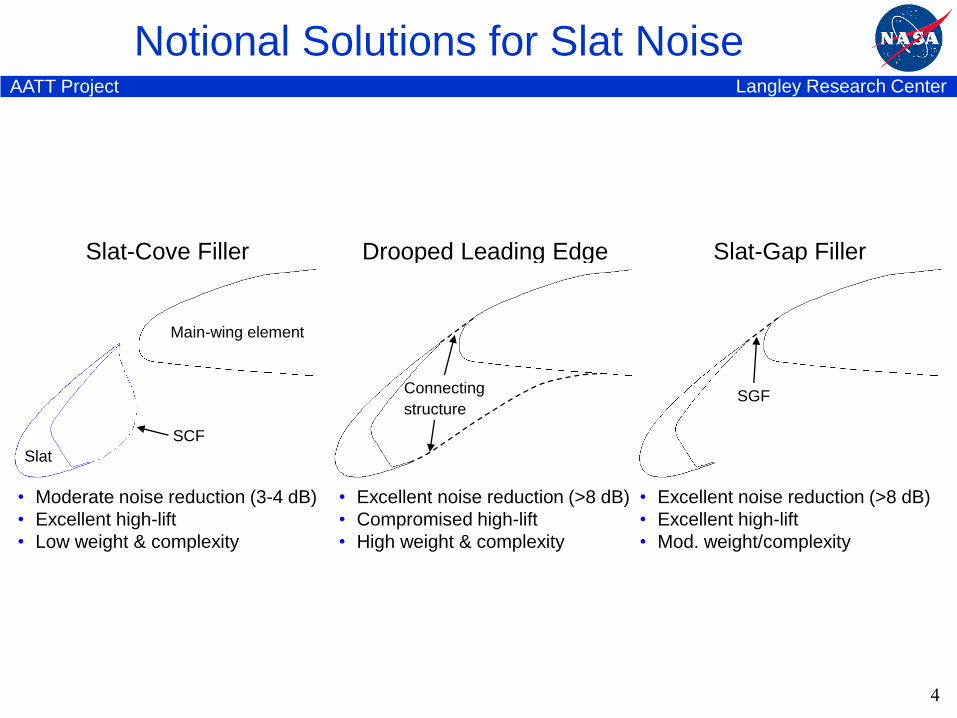
Drooped Leading Edge
• Excellent noise reduction (>8 dB)
• Compromised high-lift
• High weight & complexity
Notional Solutions for Slat Noise
Connecting
structure
Slat-Cove Filler
• Moderate noise reduction (3-4 dB)
• Excellent high-lift
• Low weight & complexity
Slat-Gap Filler
• Excellent noise reduction (>8 dB)
• Excellent high-lift
• Mod. weight/complexity
Slat
Main-wing element
SCF
SGF
4
Langley Research CenterAATT Project
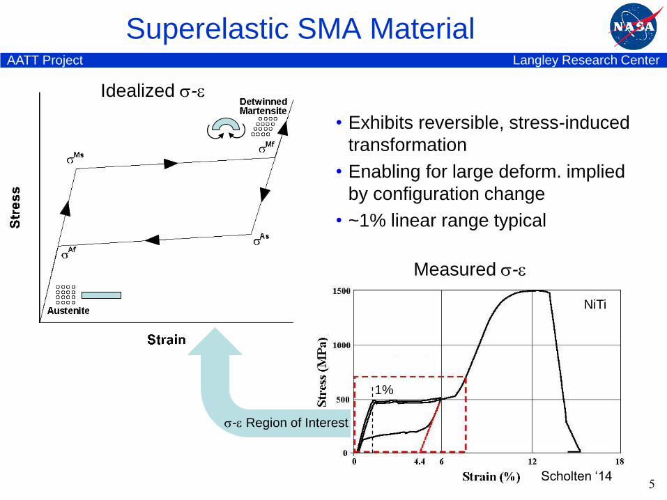
Superelastic SMA Material
5
Idealized -
Measured -
Scholten ‘14
1%
• Exhibits reversible, stress-induced
transformation
• Enabling for large deform. implied
by configuration change
• ~1% linear range typical
- Region of Interest
NiTi

Langley Research CenterAATT Project
Superelastic Slat-Cove Filler (SCF)
6
Langley Research CenterAATT Project
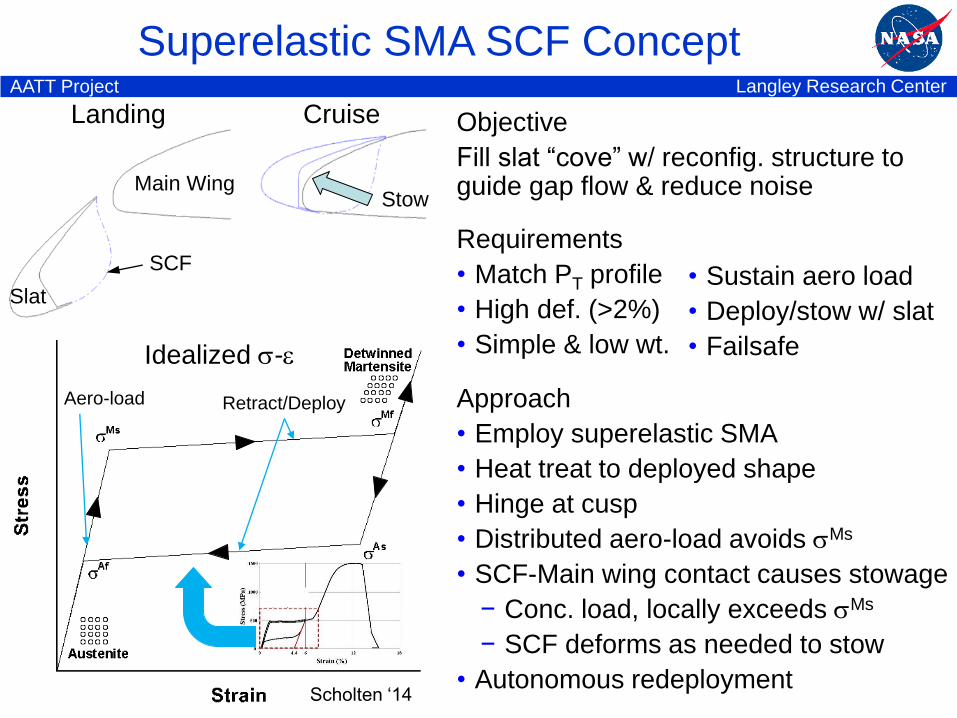
Superelastic SMA SCF Concept
Idealized -
Retract/DeployAero-load
Scholten ‘14
SCF
Slat
Main Wing
CruiseLanding
Stow
Approach
• Employ superelastic SMA
• Heat treat to deployed shape
• Hinge at cusp
• Distributed aero-load avoids Ms
• SCF-Main wing contact causes stowage
− Conc. load, locally exceeds Ms
− SCF deforms as needed to stow
• Autonomous redeployment
Objective
Fill slat “cove” w/ reconfig. structure to guide gap flow & reduce noise
Requirements
• Match PT profile
• High def. (>2%)
• Simple & low wt.
• Sustain aero load
• Deploy/stow w/ slat
• Failsafe
Langley Research CenterAATT Project
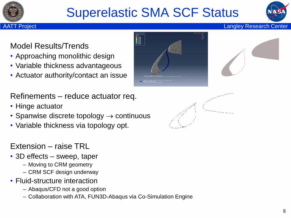
Superelastic SMA SCF Status
8
Model Results/Trends
• Approaching monolithic design
• Variable thickness advantageous
• Actuator authority/contact an issue
Refinements – reduce actuator req.
• Hinge actuator
• Spanwise discrete topology continuous
• Variable thickness via topology opt.
Extension – raise TRL
• 3D effects – sweep, taper– Moving to CRM geometry
– CRM SCF design underway
• Fluid-structure interaction– Abaqus/CFD not a good option
– Collaboration with ATA, FUN3D-Abaqus via Co-Simulation Engine
Langley Research CenterAATT Project
Shape Memory Polymer Composite SCF
9
Langley Research CenterAATT Project
SMPC SCF Status
10
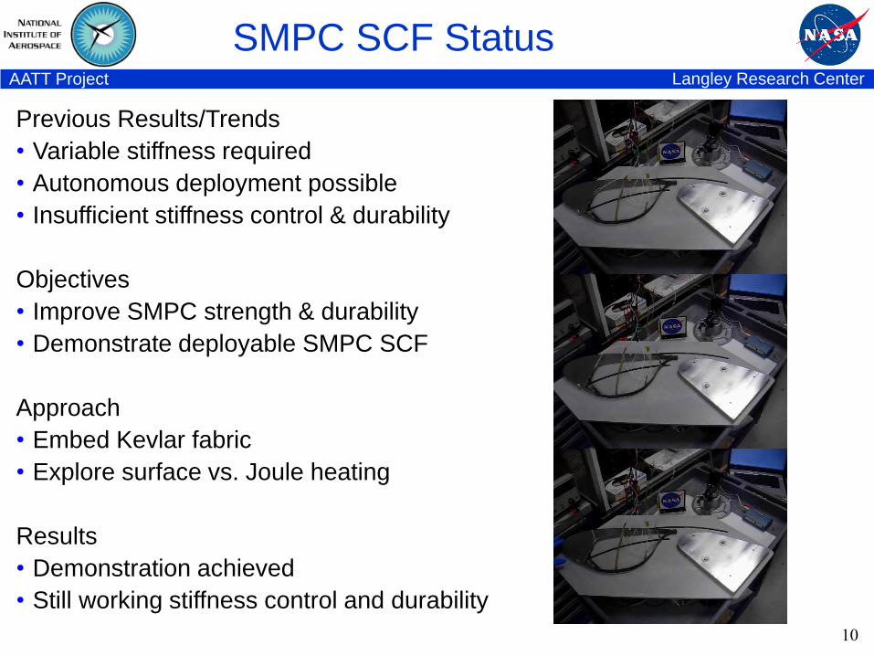
Previous Results/Trends
• Variable stiffness required
• Autonomous deployment possible
• Insufficient stiffness control & durability
Objectives
• Improve SMPC strength & durability
• Demonstrate deployable SMPC SCF
Approach
• Embed Kevlar fabric
• Explore surface vs. Joule heating
Results
• Demonstration achieved
• Still working stiffness control and durability
Langley Research CenterAATT Project
Superelastic Slat-Gap Filler (SGF)
11
Langley Research CenterAATT Project
Superelastic SMA Slat-Gap Filler (SGF)
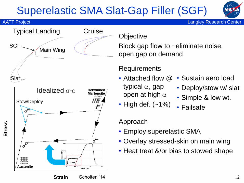
Slat
CruiseTypical Landing
SGFMain Wing
Requirements
• Attached flow @
typical , gap
open at high
• High def. (~1%)
Objective
Block gap flow to ~eliminate noise,
open gap on demand
Approach
• Employ superelastic SMA
• Overlay stressed-skin on main wing
• Heat treat &/or bias to stowed shape
12
• Sustain aero load
• Deploy/stow w/ slat
• Simple & low wt.
• Failsafe
Idealized -
Stow/Deploy
Scholten ‘14
Langley Research CenterAATT Project
Superelastic SMA Slat-Gap Filler (SGF)
13
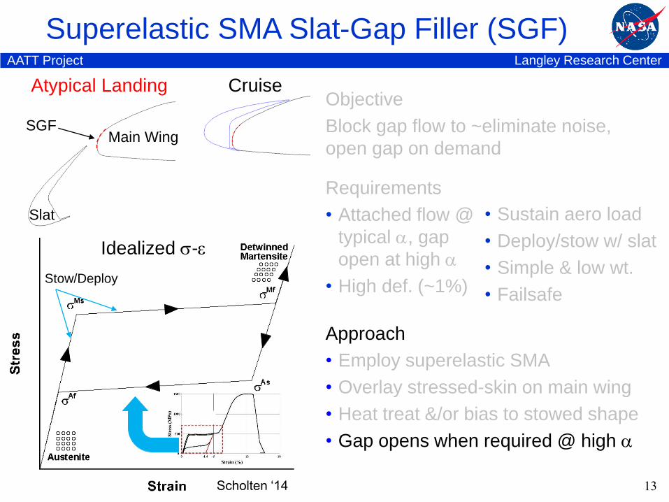
CruiseAtypical Landing
Main Wing
Slat
SGF
Idealized -
Stow/Deploy
Scholten ‘14
Approach
• Employ superelastic SMA
• Overlay stressed-skin on main wing
• Heat treat &/or bias to stowed shape
• Gap opens when required @ high
Requirements
• Attached flow @
typical , gap
open at high
• High def. (~1%)
Objective
Block gap flow to ~eliminate noise,
open gap on demand
• Sustain aero load
• Deploy/stow w/ slat
• Simple & low wt.
• Failsafe
Langley Research CenterAATT Project
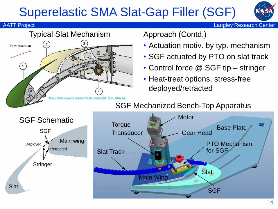
Superelastic SMA Slat-Gap Filler (SGF)
Typical Slat Mechanism
14
SGF Mechanized Bench-Top Apparatus
Approach (Contd.)
• Actuation motiv. by typ. mechanism
• SGF actuated by PTO on slat track
• Control force @ SGF tip – stringer
• Heat-treat options, stress-free
deployed/retracted
Main Wing
Base Plate
Slat Track
SGF
Gear Head
Slat
Torque
Transducer
Motor
PTO Mechanism for SGF
SGF
Slat
Main wing
Stringer
Deployed
Retracted
SGF Schematic
http://commons.wikimedia.org/wiki/File:800px-Slat_A319_colore.jpg
Langley Research CenterAATT Project
Stress-Free-Deployed (SFD) SGF
15
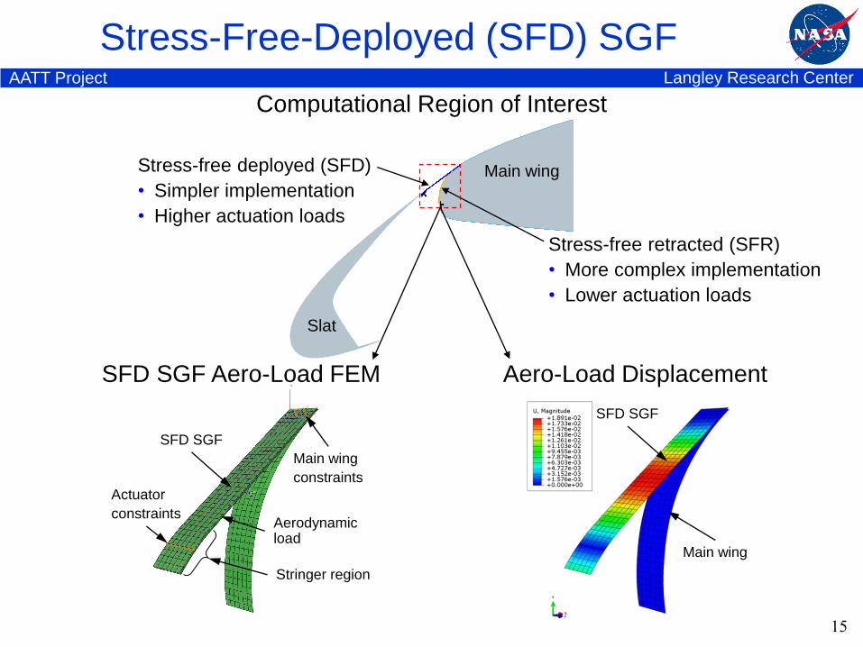
Slat
Main wing
Actuator
constraints
Main wing
constraints
Aerodynamic load
Stringer region
SFD SGF
SFD SGF Aero-Load FEM Aero-Load Displacement
Main wing
SFD SGF
Computational Region of Interest
Stress-free deployed (SFD)
• Simpler implementation
• Higher actuation loads
Stress-free retracted (SFR)
• More complex implementation
• Lower actuation loads
Langley Research CenterAATT Project
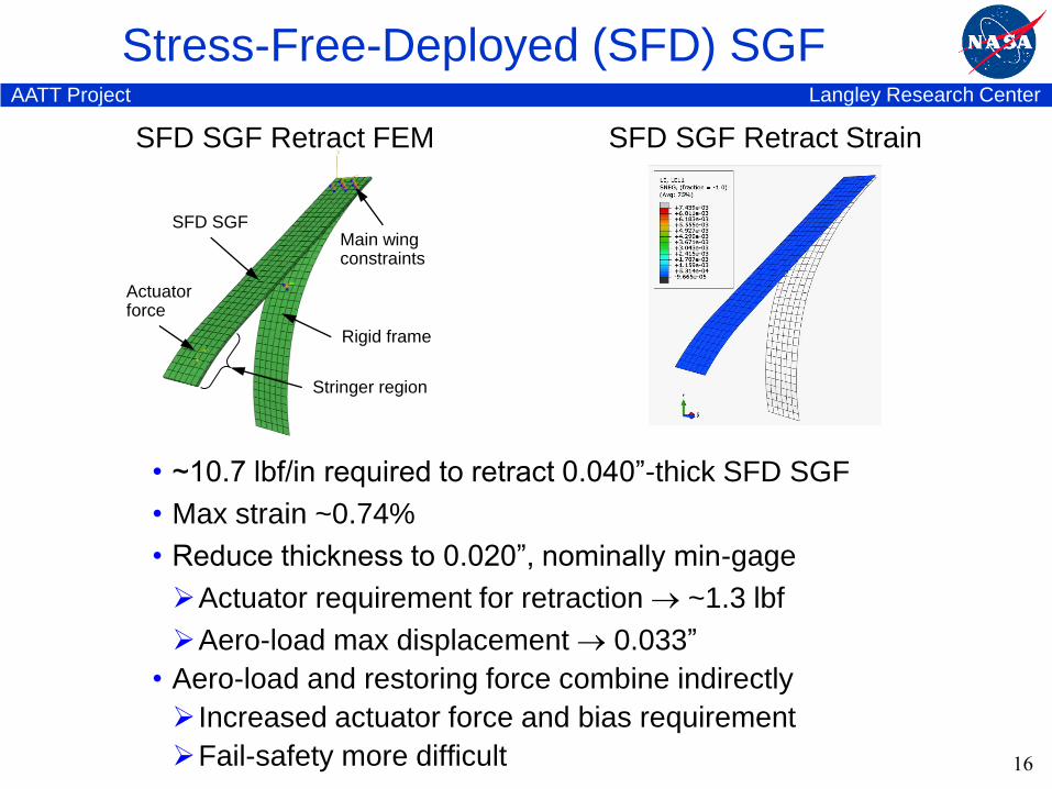
Stress-Free-Deployed (SFD) SGF
16
Actuatorforce
Main wingconstraints
Rigid frame
Stringer region
SFD SGF
SFD SGF Retract FEM SFD SGF Retract Strain
• ~10.7 lbf/in required to retract 0.040”-thick SFD SGF
• Max strain ~0.74%
• Reduce thickness to 0.020”, nominally min-gage
Actuator requirement for retraction ~1.3 lbf
Aero-load max displacement 0.033”
• Aero-load and restoring force combine indirectly
Increased actuator force and bias requirement
Fail-safety more difficult
Langley Research CenterAATT Project
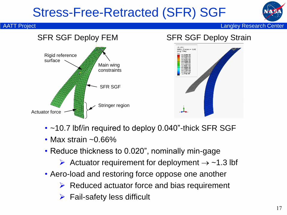
Stress-Free-Retracted (SFR) SGF
17
SFR SGF Deploy StrainSFR SGF Deploy FEM
Actuator force
Main wingconstraints
Rigid reference surface
Stringer region
SFR SGF
• ~10.7 lbf/in required to deploy 0.040”-thick SFR SGF
• Max strain ~0.66%
• Reduce thickness to 0.020”, nominally min-gage
Actuator requirement for deployment ~1.3 lbf
• Aero-load and restoring force oppose one another
Reduced actuator force and bias requirement
Fail-safety less difficult
Langley Research CenterAATT Project
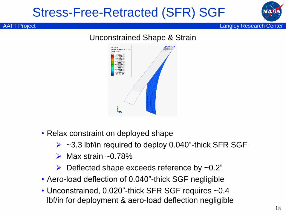
Stress-Free-Retracted (SFR) SGF
18
Unconstrained Shape & Strain
• Relax constraint on deployed shape
~3.3 lbf/in required to deploy 0.040”-thick SFR SGF
Max strain ~0.78%
Deflected shape exceeds reference by ~0.2”
• Aero-load deflection of 0.040”-thick SGF negligible
• Unconstrained, 0.020”-thick SFR SGF requires ~0.4
lbf/in for deployment & aero-load deflection negligible
Langley Research CenterAATT Project
SCF & SGF Bench-Top Testing
19
Langley Research CenterAATT Project
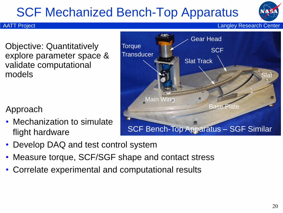
SCF Mechanized Bench-Top Apparatus
20
Main WingBase Plate
Slat Track
SCF
Gear Head
Slat
Torque
Transducer
Approach
• Mechanization to simulate
flight hardware
• Develop DAQ and test control system
• Measure torque, SCF/SGF shape and contact stress
• Correlate experimental and computational results
SCF Bench-Top Apparatus – SGF Similar
Objective: Quantitatively explore parameter space &validate computational models

Langley Research CenterAATT Project
SCF & SGF Wind Tunnel Test Prep
21
Langley Research CenterAATT Project
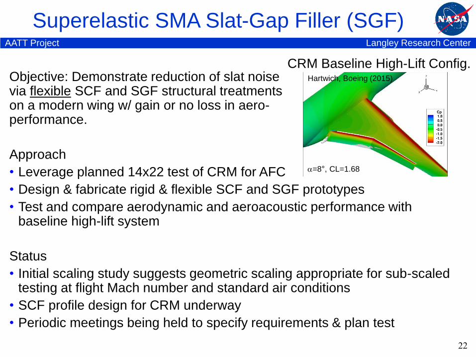
Objective: Demonstrate reduction of slat noisevia flexible SCF and SGF structural treatmentson a modern wing w/ gain or no loss in aero-performance.
Approach
• Leverage planned 14x22 test of CRM for AFC
• Design & fabricate rigid & flexible SCF and SGF prototypes
• Test and compare aerodynamic and aeroacoustic performance with baseline high-lift system
Status
• Initial scaling study suggests geometric scaling appropriate for sub-scaled testing at flight Mach number and standard air conditions
• SCF profile design for CRM underway
• Periodic meetings being held to specify requirements & plan test
Superelastic SMA Slat-Gap Filler (SGF)
22
CRM Baseline High-Lift Config.
=8°, CL=1.68
Hartwich, Boeing (2015)

23
Recommended