Embed Size (px)
Citation preview
Langley Research CenterAATT Project
Structural Implementations of
Leading‐Edge Noise Reduction Devices
Travis Turner
Airframe Noise Technical Challenge
AATT Project
Acoustics Technical Working Group Meeting
April 21-22, 2015
https://ntrs.nasa.gov/search.jsp?R=20160007338 2018-06-02T00:49:28+00:00Z
Langley Research CenterAATT Project
Aeroacoustics
• David Lockard
• Mehdi Khorrami
• Craig Streett
• John Lin
Acknowledgements
Materials & Structures
• Travis Turner
• Jim Moore
• Mia Siochi
• Jin Ho Kang, NIA
• Reggie Kidd, AMA
• Dave Long, AMA
• Darren Hartl, TAMU
• Will Scholten, TAMU
Prototype Development
• George Hilton
• Larry Becker, NG
• Ron Penner, STC
• Rick Thomas, STC
NASA AATT Project2
SMA Components
• Joe Kain, JM
• Carlos Pimentel, JM
Langley Research CenterAATT Project
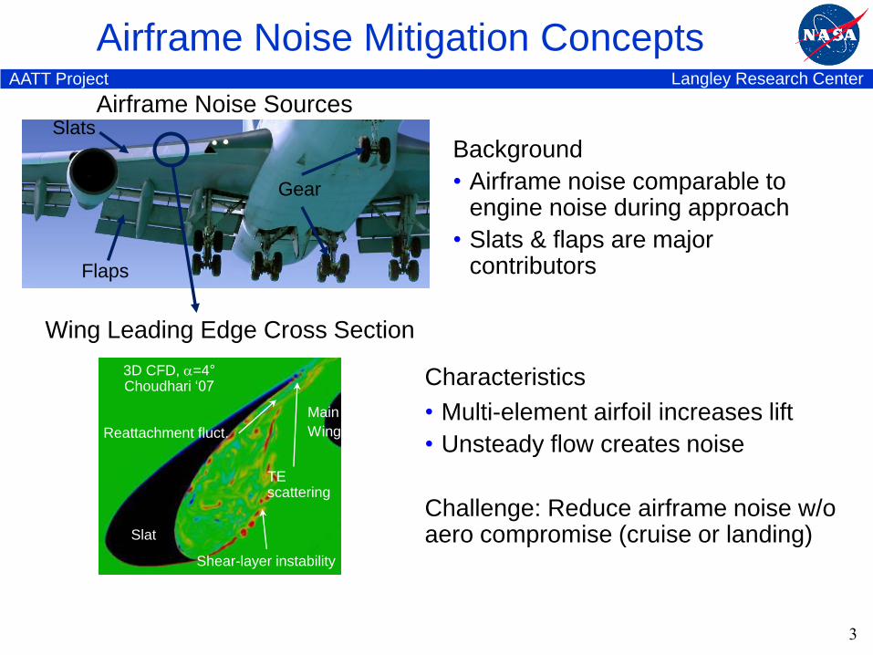
Airframe Noise Mitigation Concepts
Background
• Airframe noise comparable to engine noise during approach
• Slats & flaps are major contributorsFlaps
Slats
Gear
Airframe Noise Sources
Wing Leading Edge Cross Section
Characteristics
• Multi-element airfoil increases lift
• Unsteady flow creates noise
Challenge: Reduce airframe noise w/o aero compromise (cruise or landing)Slat
Main
Wing
Shear-layer instability
3D CFD, =4°Choudhari ‘07
Reattachment fluct.
TEscattering
3
Langley Research CenterAATT Project
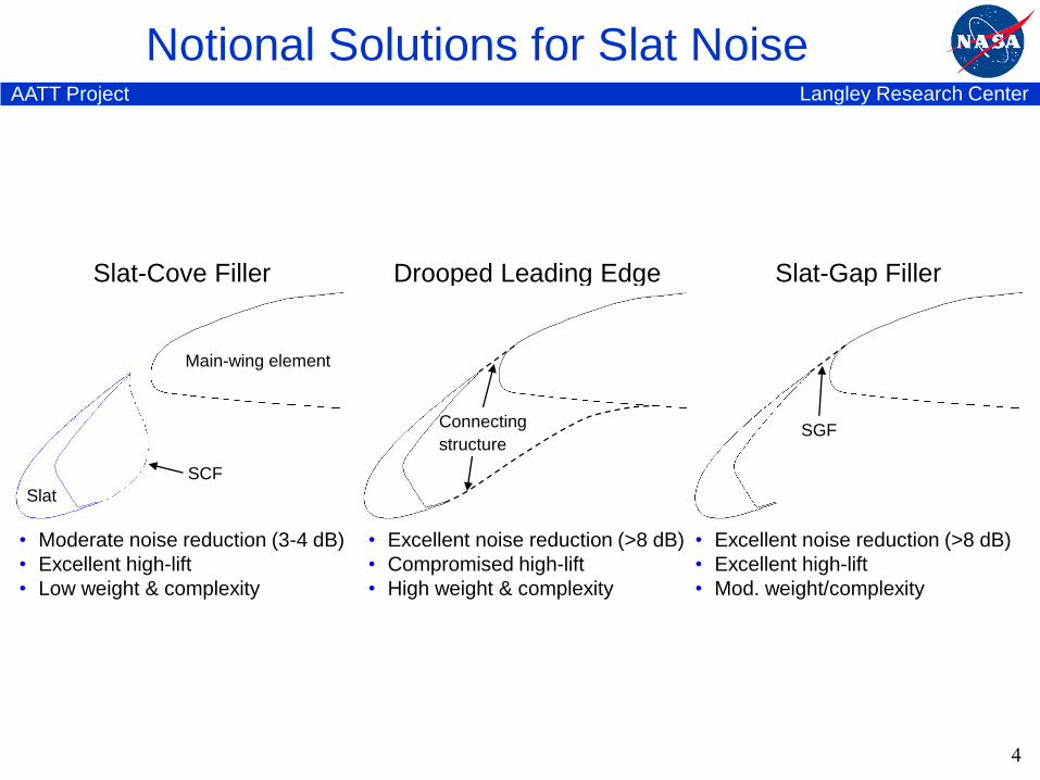
Drooped Leading Edge
• Excellent noise reduction (>8 dB)
• Compromised high-lift
• High weight & complexity
Notional Solutions for Slat Noise
Connecting
structure
Slat-Cove Filler
• Moderate noise reduction (3-4 dB)
• Excellent high-lift
• Low weight & complexity
Slat-Gap Filler
• Excellent noise reduction (>8 dB)
• Excellent high-lift
• Mod. weight/complexity
Slat
Main-wing element
SCF
SGF
4
Langley Research CenterAATT Project
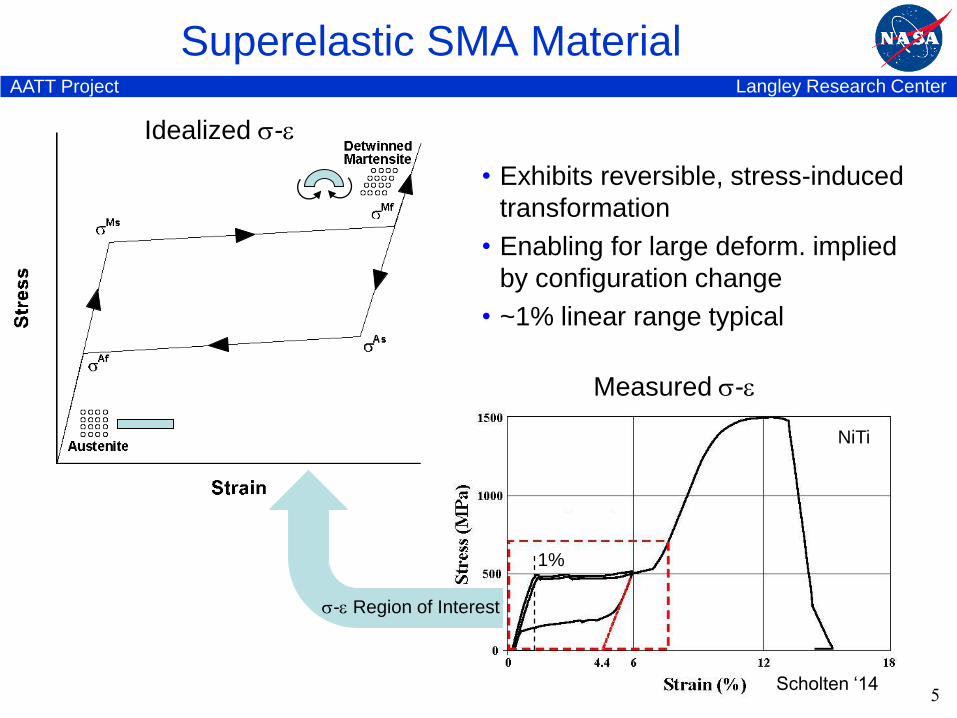
Superelastic SMA Material
5
Idealized -
Measured -
Scholten ‘14
1%
• Exhibits reversible, stress-induced
transformation
• Enabling for large deform. implied
by configuration change
• ~1% linear range typical
- Region of Interest
NiTi

Langley Research CenterAATT Project
Superelastic Slat-Cove Filler (SCF)
6
Langley Research CenterAATT Project
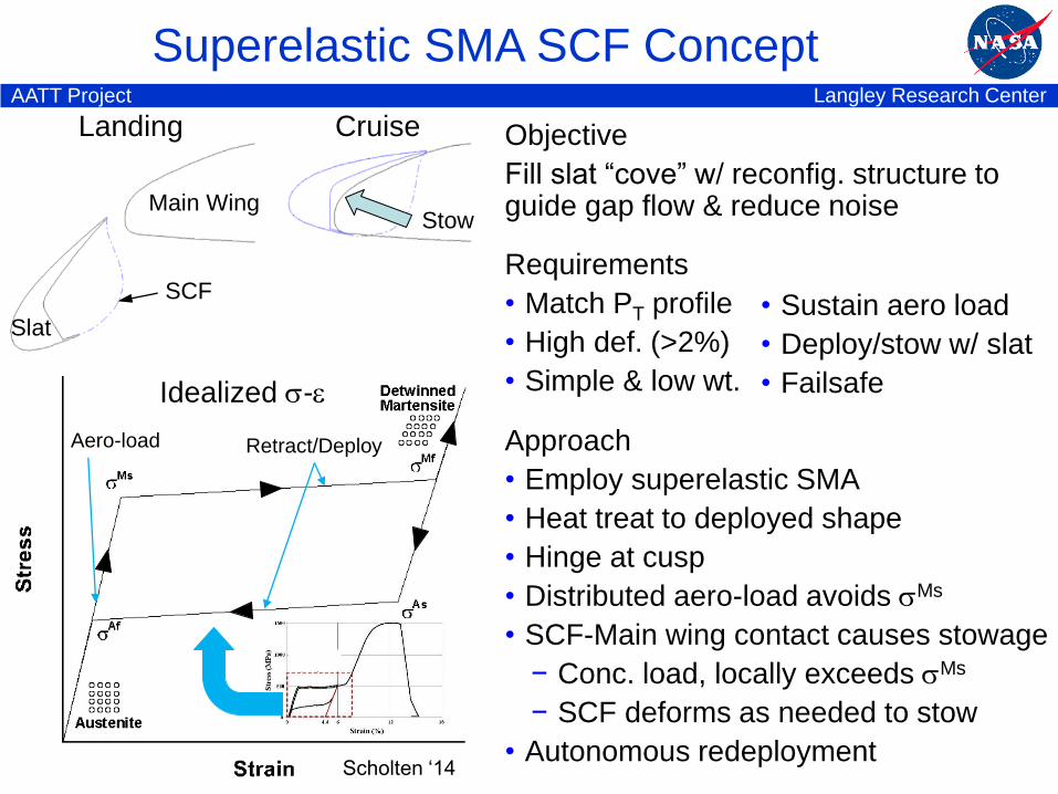
Superelastic SMA SCF Concept
Idealized -
Retract/DeployAero-load
Scholten ‘14
SCF
Slat
Main Wing
CruiseLanding
Stow
Approach
• Employ superelastic SMA
• Heat treat to deployed shape
• Hinge at cusp
• Distributed aero-load avoids Ms
• SCF-Main wing contact causes stowage
− Conc. load, locally exceeds Ms
− SCF deforms as needed to stow
• Autonomous redeployment
Objective
Fill slat “cove” w/ reconfig. structure to guide gap flow & reduce noise
Requirements
• Match PT profile
• High def. (>2%)
• Simple & low wt.
• Sustain aero load
• Deploy/stow w/ slat
• Failsafe
Langley Research CenterAATT Project
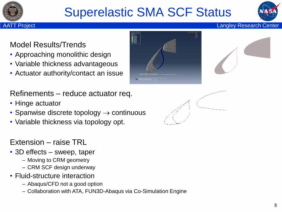
Superelastic SMA SCF Status
8
Model Results/Trends
• Approaching monolithic design
• Variable thickness advantageous
• Actuator authority/contact an issue
Refinements – reduce actuator req.
• Hinge actuator
• Spanwise discrete topology continuous
• Variable thickness via topology opt.
Extension – raise TRL
• 3D effects – sweep, taper– Moving to CRM geometry
– CRM SCF design underway
• Fluid-structure interaction– Abaqus/CFD not a good option
– Collaboration with ATA, FUN3D-Abaqus via Co-Simulation Engine
Langley Research CenterAATT Project
Shape Memory Polymer Composite SCF
9
Langley Research CenterAATT Project
SMPC SCF Status
10
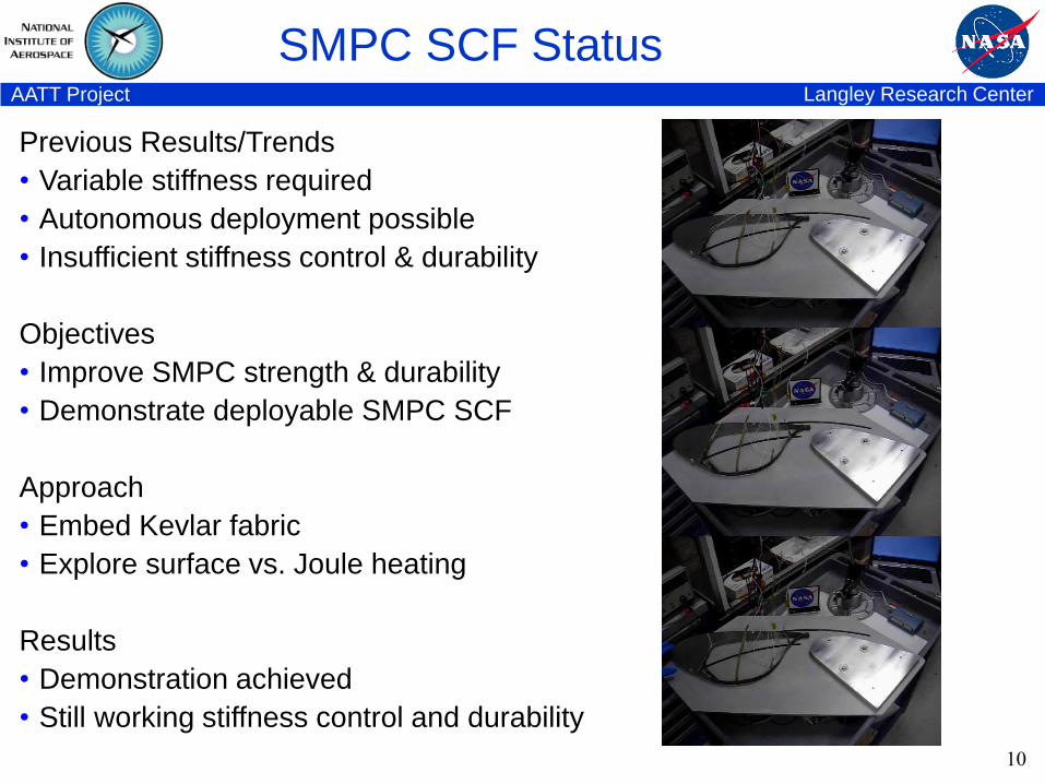
Previous Results/Trends
• Variable stiffness required
• Autonomous deployment possible
• Insufficient stiffness control & durability
Objectives
• Improve SMPC strength & durability
• Demonstrate deployable SMPC SCF
Approach
• Embed Kevlar fabric
• Explore surface vs. Joule heating
Results
• Demonstration achieved
• Still working stiffness control and durability
Langley Research CenterAATT Project
Superelastic Slat-Gap Filler (SGF)
11
Langley Research CenterAATT Project
Superelastic SMA Slat-Gap Filler (SGF)
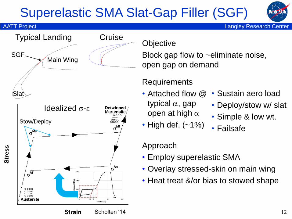
Slat
CruiseTypical Landing
SGFMain Wing
Requirements
• Attached flow @
typical , gap
open at high
• High def. (~1%)
Objective
Block gap flow to ~eliminate noise,
open gap on demand
Approach
• Employ superelastic SMA
• Overlay stressed-skin on main wing
• Heat treat &/or bias to stowed shape
12
• Sustain aero load
• Deploy/stow w/ slat
• Simple & low wt.
• Failsafe
Idealized -
Stow/Deploy
Scholten ‘14
Langley Research CenterAATT Project
Superelastic SMA Slat-Gap Filler (SGF)
13
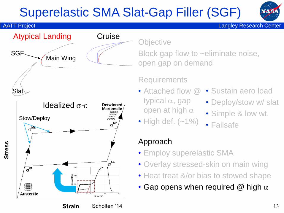
CruiseAtypical Landing
Main Wing
Slat
SGF
Idealized -
Stow/Deploy
Scholten ‘14
Approach
• Employ superelastic SMA
• Overlay stressed-skin on main wing
• Heat treat &/or bias to stowed shape
• Gap opens when required @ high
Requirements
• Attached flow @
typical , gap
open at high
• High def. (~1%)
Objective
Block gap flow to ~eliminate noise,
open gap on demand
• Sustain aero load
• Deploy/stow w/ slat
• Simple & low wt.
• Failsafe
Langley Research CenterAATT Project
Superelastic SMA Slat-Gap Filler (SGF)
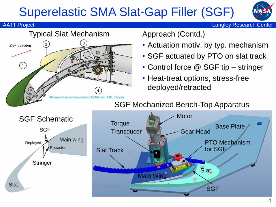
Typical Slat Mechanism
14
SGF Mechanized Bench-Top Apparatus
Approach (Contd.)
• Actuation motiv. by typ. mechanism
• SGF actuated by PTO on slat track
• Control force @ SGF tip – stringer
• Heat-treat options, stress-free
deployed/retracted
Main Wing
Base Plate
Slat Track
SGF
Gear Head
Slat
Torque
Transducer
Motor
PTO Mechanism for SGF
SGF
Slat
Main wing
Stringer
Deployed
Retracted
SGF Schematic
http://commons.wikimedia.org/wiki/File:800px-Slat_A319_colore.jpg
Langley Research CenterAATT Project
Stress-Free-Deployed (SFD) SGF
15
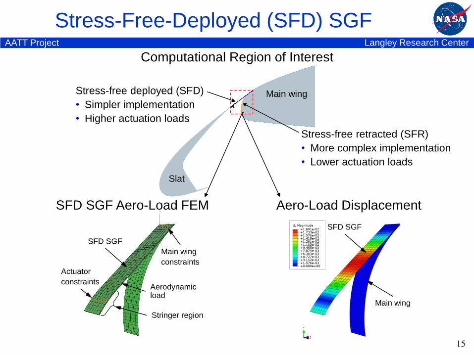
Slat
Main wing
Actuator
constraints
Main wing
constraints
Aerodynamic load
Stringer region
SFD SGF
SFD SGF Aero-Load FEM Aero-Load Displacement
Main wing
SFD SGF
Computational Region of Interest
Stress-free deployed (SFD)
• Simpler implementation
• Higher actuation loads
Stress-free retracted (SFR)
• More complex implementation
• Lower actuation loads
Langley Research CenterAATT Project
Stress-Free-Deployed (SFD) SGF
16
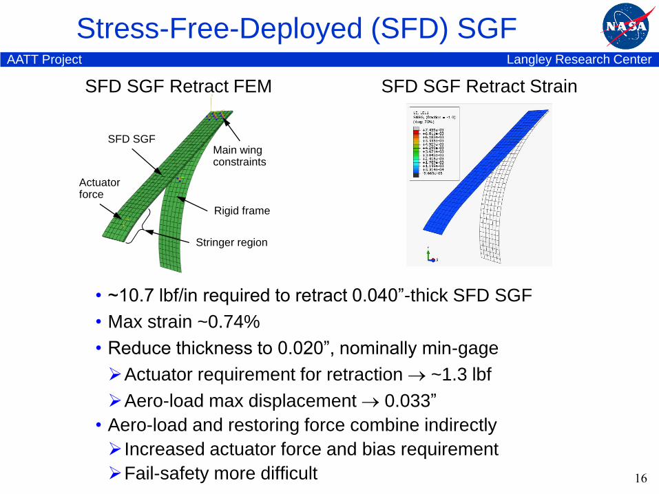
Actuatorforce
Main wingconstraints
Rigid frame
Stringer region
SFD SGF
SFD SGF Retract FEM SFD SGF Retract Strain
• ~10.7 lbf/in required to retract 0.040”-thick SFD SGF
• Max strain ~0.74%
• Reduce thickness to 0.020”, nominally min-gage
Actuator requirement for retraction ~1.3 lbf
Aero-load max displacement 0.033”
• Aero-load and restoring force combine indirectly
Increased actuator force and bias requirement
Fail-safety more difficult
Langley Research CenterAATT Project
Stress-Free-Retracted (SFR) SGF
17
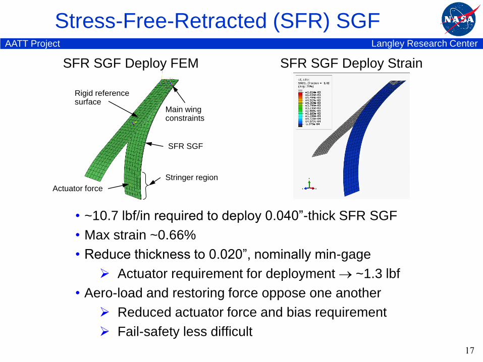
SFR SGF Deploy StrainSFR SGF Deploy FEM
Actuator force
Main wingconstraints
Rigid reference surface
Stringer region
SFR SGF
• ~10.7 lbf/in required to deploy 0.040”-thick SFR SGF
• Max strain ~0.66%
• Reduce thickness to 0.020”, nominally min-gage
Actuator requirement for deployment ~1.3 lbf
• Aero-load and restoring force oppose one another
Reduced actuator force and bias requirement
Fail-safety less difficult
Langley Research CenterAATT Project
Stress-Free-Retracted (SFR) SGF
18
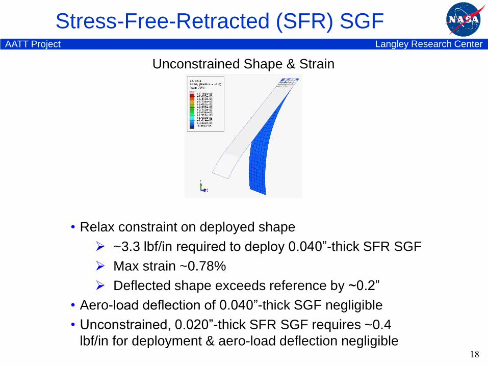
Unconstrained Shape & Strain
• Relax constraint on deployed shape
~3.3 lbf/in required to deploy 0.040”-thick SFR SGF
Max strain ~0.78%
Deflected shape exceeds reference by ~0.2”
• Aero-load deflection of 0.040”-thick SGF negligible
• Unconstrained, 0.020”-thick SFR SGF requires ~0.4
lbf/in for deployment & aero-load deflection negligible
Langley Research CenterAATT Project
SCF & SGF Bench-Top Testing
19
Langley Research CenterAATT Project
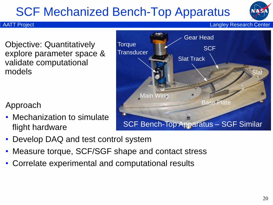
SCF Mechanized Bench-Top Apparatus
20
Main WingBase Plate
Slat Track
SCF
Gear Head
Slat
Torque
Transducer
Approach
• Mechanization to simulate
flight hardware
• Develop DAQ and test control system
• Measure torque, SCF/SGF shape and contact stress
• Correlate experimental and computational results
SCF Bench-Top Apparatus – SGF Similar
Objective: Quantitatively explore parameter space &validate computational models

Langley Research CenterAATT Project
SCF & SGF Wind Tunnel Test Prep
21
Langley Research CenterAATT Project
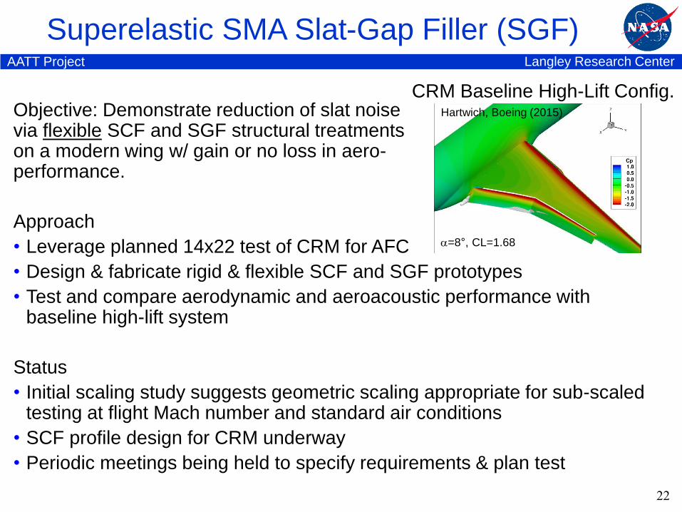
Objective: Demonstrate reduction of slat noisevia flexible SCF and SGF structural treatmentson a modern wing w/ gain or no loss in aero-performance.
Approach
• Leverage planned 14x22 test of CRM for AFC
• Design & fabricate rigid & flexible SCF and SGF prototypes
• Test and compare aerodynamic and aeroacoustic performance with baseline high-lift system
Status
• Initial scaling study suggests geometric scaling appropriate for sub-scaled testing at flight Mach number and standard air conditions
• SCF profile design for CRM underway
• Periodic meetings being held to specify requirements & plan test
Superelastic SMA Slat-Gap Filler (SGF)
22
CRM Baseline High-Lift Config.
=8°, CL=1.68
Hartwich, Boeing (2015)

23